US9375674B2 - Product gas concentrator and method associated therewith - Google Patents
Product gas concentrator and method associated therewithDownload PDFInfo
- Publication number
- US9375674B2 US9375674B2US14/202,536US201414202536AUS9375674B2US 9375674 B2US9375674 B2US 9375674B2US 201414202536 AUS201414202536 AUS 201414202536AUS 9375674 B2US9375674 B2US 9375674B2
- Authority
- US
- United States
- Prior art keywords
- flow
- sieve
- bleed
- product gas
- output setting
- Prior art date
- Legal status (The legal status is an assumption and is not a legal conclusion. Google has not performed a legal analysis and makes no representation as to the accuracy of the status listed.)
- Active, expires
Links
Images


Classifications
- A—HUMAN NECESSITIES
- A61—MEDICAL OR VETERINARY SCIENCE; HYGIENE
- A61M—DEVICES FOR INTRODUCING MEDIA INTO, OR ONTO, THE BODY; DEVICES FOR TRANSDUCING BODY MEDIA OR FOR TAKING MEDIA FROM THE BODY; DEVICES FOR PRODUCING OR ENDING SLEEP OR STUPOR
- A61M16/00—Devices for influencing the respiratory system of patients by gas treatment, e.g. ventilators; Tracheal tubes
- A61M16/20—Valves specially adapted to medical respiratory devices
- A61M16/201—Controlled valves
- A61M16/202—Controlled valves electrically actuated
- B—PERFORMING OPERATIONS; TRANSPORTING
- B01—PHYSICAL OR CHEMICAL PROCESSES OR APPARATUS IN GENERAL
- B01D—SEPARATION
- B01D53/00—Separation of gases or vapours; Recovering vapours of volatile solvents from gases; Chemical or biological purification of waste gases, e.g. engine exhaust gases, smoke, fumes, flue gases, aerosols
- B01D53/02—Separation of gases or vapours; Recovering vapours of volatile solvents from gases; Chemical or biological purification of waste gases, e.g. engine exhaust gases, smoke, fumes, flue gases, aerosols by adsorption, e.g. preparative gas chromatography
- B01D53/04—Separation of gases or vapours; Recovering vapours of volatile solvents from gases; Chemical or biological purification of waste gases, e.g. engine exhaust gases, smoke, fumes, flue gases, aerosols by adsorption, e.g. preparative gas chromatography with stationary adsorbents
- B01D53/0407—Constructional details of adsorbing systems
- B—PERFORMING OPERATIONS; TRANSPORTING
- B01—PHYSICAL OR CHEMICAL PROCESSES OR APPARATUS IN GENERAL
- B01D—SEPARATION
- B01D53/00—Separation of gases or vapours; Recovering vapours of volatile solvents from gases; Chemical or biological purification of waste gases, e.g. engine exhaust gases, smoke, fumes, flue gases, aerosols
- B01D53/02—Separation of gases or vapours; Recovering vapours of volatile solvents from gases; Chemical or biological purification of waste gases, e.g. engine exhaust gases, smoke, fumes, flue gases, aerosols by adsorption, e.g. preparative gas chromatography
- B01D53/04—Separation of gases or vapours; Recovering vapours of volatile solvents from gases; Chemical or biological purification of waste gases, e.g. engine exhaust gases, smoke, fumes, flue gases, aerosols by adsorption, e.g. preparative gas chromatography with stationary adsorbents
- B01D53/047—Pressure swing adsorption
- A—HUMAN NECESSITIES
- A61—MEDICAL OR VETERINARY SCIENCE; HYGIENE
- A61M—DEVICES FOR INTRODUCING MEDIA INTO, OR ONTO, THE BODY; DEVICES FOR TRANSDUCING BODY MEDIA OR FOR TAKING MEDIA FROM THE BODY; DEVICES FOR PRODUCING OR ENDING SLEEP OR STUPOR
- A61M16/00—Devices for influencing the respiratory system of patients by gas treatment, e.g. ventilators; Tracheal tubes
- A61M16/0057—Pumps therefor
- A61M16/0063—Compressors
- A—HUMAN NECESSITIES
- A61—MEDICAL OR VETERINARY SCIENCE; HYGIENE
- A61M—DEVICES FOR INTRODUCING MEDIA INTO, OR ONTO, THE BODY; DEVICES FOR TRANSDUCING BODY MEDIA OR FOR TAKING MEDIA FROM THE BODY; DEVICES FOR PRODUCING OR ENDING SLEEP OR STUPOR
- A61M16/00—Devices for influencing the respiratory system of patients by gas treatment, e.g. ventilators; Tracheal tubes
- A61M16/06—Respiratory or anaesthetic masks
- A61M16/0666—Nasal cannulas or tubing
- A61M16/0672—Nasal cannula assemblies for oxygen therapy
- A61M16/0677—Gas-saving devices therefor
- A—HUMAN NECESSITIES
- A61—MEDICAL OR VETERINARY SCIENCE; HYGIENE
- A61M—DEVICES FOR INTRODUCING MEDIA INTO, OR ONTO, THE BODY; DEVICES FOR TRANSDUCING BODY MEDIA OR FOR TAKING MEDIA FROM THE BODY; DEVICES FOR PRODUCING OR ENDING SLEEP OR STUPOR
- A61M16/00—Devices for influencing the respiratory system of patients by gas treatment, e.g. ventilators; Tracheal tubes
- A61M16/10—Preparation of respiratory gases or vapours
- A61M16/1005—Preparation of respiratory gases or vapours with O2 features or with parameter measurement
- A61M16/101—Preparation of respiratory gases or vapours with O2 features or with parameter measurement using an oxygen concentrator
- A—HUMAN NECESSITIES
- A61—MEDICAL OR VETERINARY SCIENCE; HYGIENE
- A61M—DEVICES FOR INTRODUCING MEDIA INTO, OR ONTO, THE BODY; DEVICES FOR TRANSDUCING BODY MEDIA OR FOR TAKING MEDIA FROM THE BODY; DEVICES FOR PRODUCING OR ENDING SLEEP OR STUPOR
- A61M16/00—Devices for influencing the respiratory system of patients by gas treatment, e.g. ventilators; Tracheal tubes
- A61M16/10—Preparation of respiratory gases or vapours
- A61M16/105—Filters
- B—PERFORMING OPERATIONS; TRANSPORTING
- B01—PHYSICAL OR CHEMICAL PROCESSES OR APPARATUS IN GENERAL
- B01D—SEPARATION
- B01D53/00—Separation of gases or vapours; Recovering vapours of volatile solvents from gases; Chemical or biological purification of waste gases, e.g. engine exhaust gases, smoke, fumes, flue gases, aerosols
- B01D53/02—Separation of gases or vapours; Recovering vapours of volatile solvents from gases; Chemical or biological purification of waste gases, e.g. engine exhaust gases, smoke, fumes, flue gases, aerosols by adsorption, e.g. preparative gas chromatography
- B01D53/04—Separation of gases or vapours; Recovering vapours of volatile solvents from gases; Chemical or biological purification of waste gases, e.g. engine exhaust gases, smoke, fumes, flue gases, aerosols by adsorption, e.g. preparative gas chromatography with stationary adsorbents
- B01D53/047—Pressure swing adsorption
- B01D53/053—Pressure swing adsorption with storage or buffer vessel
- A—HUMAN NECESSITIES
- A61—MEDICAL OR VETERINARY SCIENCE; HYGIENE
- A61M—DEVICES FOR INTRODUCING MEDIA INTO, OR ONTO, THE BODY; DEVICES FOR TRANSDUCING BODY MEDIA OR FOR TAKING MEDIA FROM THE BODY; DEVICES FOR PRODUCING OR ENDING SLEEP OR STUPOR
- A61M16/00—Devices for influencing the respiratory system of patients by gas treatment, e.g. ventilators; Tracheal tubes
- A61M16/10—Preparation of respiratory gases or vapours
- A61M16/105—Filters
- A61M16/106—Filters in a path
- A61M16/107—Filters in a path in the inspiratory path
- A—HUMAN NECESSITIES
- A61—MEDICAL OR VETERINARY SCIENCE; HYGIENE
- A61M—DEVICES FOR INTRODUCING MEDIA INTO, OR ONTO, THE BODY; DEVICES FOR TRANSDUCING BODY MEDIA OR FOR TAKING MEDIA FROM THE BODY; DEVICES FOR PRODUCING OR ENDING SLEEP OR STUPOR
- A61M16/00—Devices for influencing the respiratory system of patients by gas treatment, e.g. ventilators; Tracheal tubes
- A61M16/0003—Accessories therefor, e.g. sensors, vibrators, negative pressure
- A61M2016/0027—Accessories therefor, e.g. sensors, vibrators, negative pressure pressure meter
- A—HUMAN NECESSITIES
- A61—MEDICAL OR VETERINARY SCIENCE; HYGIENE
- A61M—DEVICES FOR INTRODUCING MEDIA INTO, OR ONTO, THE BODY; DEVICES FOR TRANSDUCING BODY MEDIA OR FOR TAKING MEDIA FROM THE BODY; DEVICES FOR PRODUCING OR ENDING SLEEP OR STUPOR
- A61M16/00—Devices for influencing the respiratory system of patients by gas treatment, e.g. ventilators; Tracheal tubes
- A61M16/0003—Accessories therefor, e.g. sensors, vibrators, negative pressure
- A61M2016/003—Accessories therefor, e.g. sensors, vibrators, negative pressure with a flowmeter
- A61M2016/0033—Accessories therefor, e.g. sensors, vibrators, negative pressure with a flowmeter electrical
- A61M2016/0036—Accessories therefor, e.g. sensors, vibrators, negative pressure with a flowmeter electrical in the breathing tube and used in both inspiratory and expiratory phase
- A—HUMAN NECESSITIES
- A61—MEDICAL OR VETERINARY SCIENCE; HYGIENE
- A61M—DEVICES FOR INTRODUCING MEDIA INTO, OR ONTO, THE BODY; DEVICES FOR TRANSDUCING BODY MEDIA OR FOR TAKING MEDIA FROM THE BODY; DEVICES FOR PRODUCING OR ENDING SLEEP OR STUPOR
- A61M2205/00—General characteristics of the apparatus
- A61M2205/02—General characteristics of the apparatus characterised by a particular materials
- A61M2205/0216—Materials providing elastic properties, e.g. for facilitating deformation and avoid breaking
- A—HUMAN NECESSITIES
- A61—MEDICAL OR VETERINARY SCIENCE; HYGIENE
- A61M—DEVICES FOR INTRODUCING MEDIA INTO, OR ONTO, THE BODY; DEVICES FOR TRANSDUCING BODY MEDIA OR FOR TAKING MEDIA FROM THE BODY; DEVICES FOR PRODUCING OR ENDING SLEEP OR STUPOR
- A61M2205/00—General characteristics of the apparatus
- A61M2205/50—General characteristics of the apparatus with microprocessors or computers
- A61M2205/502—User interfaces, e.g. screens or keyboards
- A—HUMAN NECESSITIES
- A61—MEDICAL OR VETERINARY SCIENCE; HYGIENE
- A61M—DEVICES FOR INTRODUCING MEDIA INTO, OR ONTO, THE BODY; DEVICES FOR TRANSDUCING BODY MEDIA OR FOR TAKING MEDIA FROM THE BODY; DEVICES FOR PRODUCING OR ENDING SLEEP OR STUPOR
- A61M2205/00—General characteristics of the apparatus
- A61M2205/75—General characteristics of the apparatus with filters
- A61M2205/7536—General characteristics of the apparatus with filters allowing gas passage, but preventing liquid passage, e.g. liquophobic, hydrophobic, water-repellent membranes
- A—HUMAN NECESSITIES
- A61—MEDICAL OR VETERINARY SCIENCE; HYGIENE
- A61M—DEVICES FOR INTRODUCING MEDIA INTO, OR ONTO, THE BODY; DEVICES FOR TRANSDUCING BODY MEDIA OR FOR TAKING MEDIA FROM THE BODY; DEVICES FOR PRODUCING OR ENDING SLEEP OR STUPOR
- A61M2230/00—Measuring parameters of the user
- A61M2230/005—Parameter used as control input for the apparatus
- A—HUMAN NECESSITIES
- A61—MEDICAL OR VETERINARY SCIENCE; HYGIENE
- A61M—DEVICES FOR INTRODUCING MEDIA INTO, OR ONTO, THE BODY; DEVICES FOR TRANSDUCING BODY MEDIA OR FOR TAKING MEDIA FROM THE BODY; DEVICES FOR PRODUCING OR ENDING SLEEP OR STUPOR
- A61M2230/00—Measuring parameters of the user
- A61M2230/40—Respiratory characteristics
- B—PERFORMING OPERATIONS; TRANSPORTING
- B01—PHYSICAL OR CHEMICAL PROCESSES OR APPARATUS IN GENERAL
- B01D—SEPARATION
- B01D2253/00—Adsorbents used in seperation treatment of gases and vapours
- B01D2253/10—Inorganic adsorbents
- B01D2253/106—Silica or silicates
- B01D2253/108—Zeolites
- B—PERFORMING OPERATIONS; TRANSPORTING
- B01—PHYSICAL OR CHEMICAL PROCESSES OR APPARATUS IN GENERAL
- B01D—SEPARATION
- B01D2256/00—Main component in the product gas stream after treatment
- B01D2256/12—Oxygen
- B—PERFORMING OPERATIONS; TRANSPORTING
- B01—PHYSICAL OR CHEMICAL PROCESSES OR APPARATUS IN GENERAL
- B01D—SEPARATION
- B01D2257/00—Components to be removed
- B01D2257/10—Single element gases other than halogens
- B01D2257/102—Nitrogen
- B—PERFORMING OPERATIONS; TRANSPORTING
- B01—PHYSICAL OR CHEMICAL PROCESSES OR APPARATUS IN GENERAL
- B01D—SEPARATION
- B01D2257/00—Components to be removed
- B01D2257/50—Carbon oxides
- B01D2257/502—Carbon monoxide
- B—PERFORMING OPERATIONS; TRANSPORTING
- B01—PHYSICAL OR CHEMICAL PROCESSES OR APPARATUS IN GENERAL
- B01D—SEPARATION
- B01D2257/00—Components to be removed
- B01D2257/50—Carbon oxides
- B01D2257/504—Carbon dioxide
- B—PERFORMING OPERATIONS; TRANSPORTING
- B01—PHYSICAL OR CHEMICAL PROCESSES OR APPARATUS IN GENERAL
- B01D—SEPARATION
- B01D2257/00—Components to be removed
- B01D2257/80—Water
- B—PERFORMING OPERATIONS; TRANSPORTING
- B01—PHYSICAL OR CHEMICAL PROCESSES OR APPARATUS IN GENERAL
- B01D—SEPARATION
- B01D2259/00—Type of treatment
- B01D2259/40—Further details for adsorption processes and devices
- B01D2259/40007—Controlling pressure or temperature swing adsorption
- B01D2259/40009—Controlling pressure or temperature swing adsorption using sensors or gas analysers
- B—PERFORMING OPERATIONS; TRANSPORTING
- B01—PHYSICAL OR CHEMICAL PROCESSES OR APPARATUS IN GENERAL
- B01D—SEPARATION
- B01D2259/00—Type of treatment
- B01D2259/40—Further details for adsorption processes and devices
- B01D2259/40011—Methods relating to the process cycle in pressure or temperature swing adsorption
- B01D2259/40035—Equalization
- B—PERFORMING OPERATIONS; TRANSPORTING
- B01—PHYSICAL OR CHEMICAL PROCESSES OR APPARATUS IN GENERAL
- B01D—SEPARATION
- B01D2259/00—Type of treatment
- B01D2259/40—Further details for adsorption processes and devices
- B01D2259/40011—Methods relating to the process cycle in pressure or temperature swing adsorption
- B01D2259/40043—Purging
- B—PERFORMING OPERATIONS; TRANSPORTING
- B01—PHYSICAL OR CHEMICAL PROCESSES OR APPARATUS IN GENERAL
- B01D—SEPARATION
- B01D2259/00—Type of treatment
- B01D2259/40—Further details for adsorption processes and devices
- B01D2259/402—Further details for adsorption processes and devices using two beds
- B—PERFORMING OPERATIONS; TRANSPORTING
- B01—PHYSICAL OR CHEMICAL PROCESSES OR APPARATUS IN GENERAL
- B01D—SEPARATION
- B01D2259/00—Type of treatment
- B01D2259/45—Gas separation or purification devices adapted for specific applications
- B01D2259/4533—Gas separation or purification devices adapted for specific applications for medical purposes
- Y02C10/08—
- Y—GENERAL TAGGING OF NEW TECHNOLOGICAL DEVELOPMENTS; GENERAL TAGGING OF CROSS-SECTIONAL TECHNOLOGIES SPANNING OVER SEVERAL SECTIONS OF THE IPC; TECHNICAL SUBJECTS COVERED BY FORMER USPC CROSS-REFERENCE ART COLLECTIONS [XRACs] AND DIGESTS
- Y02—TECHNOLOGIES OR APPLICATIONS FOR MITIGATION OR ADAPTATION AGAINST CLIMATE CHANGE
- Y02C—CAPTURE, STORAGE, SEQUESTRATION OR DISPOSAL OF GREENHOUSE GASES [GHG]
- Y02C20/00—Capture or disposal of greenhouse gases
- Y02C20/40—Capture or disposal of greenhouse gases of CO2
Definitions
- an apparatus associated with providing a concentrated product gasincludes an input device adapted to select a desired output setting for the concentrated product gas from a plurality of output settings, first and second sieve tanks arranged to separate one or more adsorbable components from a pressurized source gaseous mixture in alternating and opposing pressurization and purging cycles to form the concentrated product gas, a variable restrictor to selectively provide an adjustable flow between the first and second sieve tanks, and a controller in operative communication with the input device and variable restrictor to selectively control the variable restrictor based at least in part on the desired output setting such that the flow between the first and second sieve tanks for at least one output setting is different from the flow between the first and second sieve tanks for at least one other output setting in relation to corresponding pressurization cycles.
- the apparatusincludes first and second sieve tanks arranged to separate one or more adsorbable components from a pressurized source gaseous mixture in alternating and opposing pressurization and purging cycles to form the concentrated product gas and a controller in operative communication with the first and second sieve tanks to selectively control the pressurization and purging cycles over a plurality of predetermined altitude ranges while maintaining an acceptable purity level for the concentrated product gas.
- the apparatusincludes an input device to select a first desired output setting for the concentrated product gas, a product gas source to provide the concentrated product gas for dispensing, a pressure sensor monitoring a pressure of the concentrated product gas, a conserver valve including an output connection associated with a user, a vent connection associated with a vent port, and a gas connection associated with the concentrated product gas, wherein the output connection is switched from the vent connection to the gas connection and vice versa, and a controller in operative communication with the input device and pressure sensor to selectively switch the conserver valve to selectively dispense the concentrated product gas based at least in part on the selected output setting and monitored pressure.
- the apparatusincludes a body forming an assembly with a sieve bed portion and a product tank portion separated by a common wall, the sieve bed portion adapted to separate one or more adsorbable components from a pressurized source gaseous mixture, the product tank portion adapted to store a volume of concentrated product gas.
- the apparatusincludes a frame comprising a plurality of structural support members forming a cage-like structure and a compressor suspended within the frame by a plurality of suspension members and adapted to provide a pressurized source gaseous mixture to first and second sieve tanks of a product gas concentrator.
- the apparatusincludes a main body enclosing a filter, the filter adapted to filter a concentrated product gas from a product gas source and provide filtered product gas.
- a method associated with providing a concentrated product gasincludes: a) selecting a desired output setting for the concentrated product gas from a plurality of output settings, b) separating one or more adsorbable components from a pressurized source gaseous mixture via first and second sieve tanks in alternating and opposing pressurization and purging cycles to form the concentrated product gas, and c) selectively controlling a variable restrictor based at least in part on the desired output setting to selectively provide flow between the first and second sieve tanks such that the flow between the first and second sieve tanks for at least one output setting is different from the flow between the first and second sieve tanks for at least one other output setting in relation to corresponding pressurization cycles.
- the methodincludes: a) separating one or more adsorbable components from a pressurized source gaseous mixture via first and second sieve tanks in alternating and opposing pressurization and purging cycles to form the concentrated product gas and b) selectively controlling the pressurization and purging cycles over a plurality of predetermined altitude ranges while maintaining an acceptable purity level for the concentrated product gas.
- the methodincludes: a) selecting a first desired output setting for the concentrated product gas, b) providing a product gas source for supplying the concentrated product gas to be dispensed, c) monitoring a pressure of the concentrated product gas, and d) selectively switching an output connection associated with a user from a vent connection associated with a vent port to a gas connection associated with the concentrated product gas and vice versa to selectively dispense the concentrated product gas based at least in part on the selected output setting and monitored pressure.
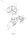
- FIG. 1provides a perspective view of an exemplary embodiment of a product gas concentrator
- FIG. 2provides an exploded view of the product gas concentrator of FIG. 1 ;
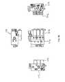
- FIGS. 3A-Hprovide various perspective, sectional, exploded views of an exemplary embodiment of a sieve bed and product tank assembly for an exemplary product gas concentrator
- FIGS. 3I-Oprovide various perspective, sectional, exploded views of an alternate exemplary embodiment of an end cap for the sieve bed and product tank assembly of FIG. 3A ;
- FIGS. 4A-Dprovide various perspective, sectional, exploded views of an exemplary embodiment of a compressor assembly for an exemplary product gas concentrator
- FIG. 4Eprovides a top view of an alternate exemplary embodiment of a plurality of suspension links for the compressor assembly of FIG. 4A ;
- FIG. 4Fprovide a perspective view of another exemplary embodiment of a compressor assembly for an exemplary product gas concentrator
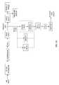
- FIG. 5Aprovides several block diagrams of an exemplary embodiment of another product gas concentrator
- FIG. 5Bprovides a timing diagram for an exemplary embodiment of a valve control scheme for the product gas concentrator of FIG. 5A ;
- FIG. 5Cprovides a block diagram showing several exemplary strategies for bleed flow from sieve tank 1 to sieve tank 2 in an exemplary embodiment of an exemplary product gas concentrator;
- FIG. 5Dprovides a block diagram showing several strategies for bleed flow from sieve tank 2 to sieve tank 1 in an exemplary embodiment of an exemplary product gas concentrator
- FIG. 5Eprovides top and side views of an exemplary embodiment of a valve assembly for the product gas concentrator of FIG. 5A ;
- FIG. 5Fprovides a block diagram of the valve assembly of FIG. 5E ;
- FIGS. 6A and Bprovide perspective and sectional views of an exemplary embodiment of an output port for an exemplary product gas concentrator
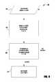
- FIG. 7provides a flow chart of an exemplary embodiment of a process for determining pressure in relation to an exemplary pressure sensor in an exemplary product gas concentrator
- FIG. 8provides a flow chart of an exemplary embodiment of a process for determining a time duration for dispensing a bolus of concentrated product gas in an exemplary product gas concentrator
- FIG. 9provides a timing diagram for an exemplary embodiment of a conserver valve control scheme for an exemplary product gas concentrator
- FIG. 10provides a block diagram of still another exemplary embodiment of a product gas concentrator.
- FIG. 11provides a flow chart of an exemplary embodiment of a process for dispensing a concentrated product gas to a user in conjunction with a product gas concentrator.
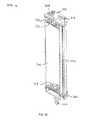
- Oxygen concentrator 100includes a housing 102 having a front portion 104 and a rear portion 106 . Front and rear portions 104 and 106 include a plurality of openings for the intake and discharge of various gases such as, for example, the intake of room air and the discharge of nitrogen and other gases.
- Oxygen concentrator 100generally intakes room air, which is mostly comprised of oxygen and nitrogen, and separates the nitrogen from the oxygen.
- the oxygenis stored in a storage tank and the nitrogen is discharged back into the room air.
- the oxygen gasmay be discharged through port 108 a patient through tubing and nasal cannula.
- FIG. 2is an exploded perspective of the oxygen concentrator 100 of FIG. 1 .
- Oxygen concentrator 100further includes a central frame 202 having a circuit board and other components connected thereto. These components include a battery pack 204 , sieve bed and product tank assemblies 206 and 208 , cooling fan 212 , and valve assembly 214 . While these components are described as being connected to central frame 202 that need not be the case. One or more of these components may be connected to housing portions 104 or 106 . Other components are also housed within oxygen concentrator 100 including, for example, compressor assembly 210 , sound attenuators or mufflers 216 and 218 and inlet filter 220 .
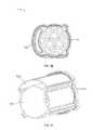
- Assembly 206includes a body having a sieve bed portion 300 and a product tank portion 302 .
- the distal ends of the bodyhave first and second end caps 304 and 306 .
- End cap 304includes outlet ports 308 and 310 .
- Outlet port 308is associated with the sieve bed portion 300 and outlet port 310 is associated with the product tank portion 302 .
- End cap 306includes input ports 312 and 314 .
- Input port 312is associated with sieve bed portion 300 and input port 314 is associated with product tank portion 302 .
- End caps 304 and 306are suitably connected to the body of assembly 206 with fasteners such as screws or bolts, although any other suitable attachment means may also be used.
- FIGS. 3C and 3Dillustrate section views taken along section lines 3 C- 3 C and 3 D- 3 D of FIG. 3A .
- Sieve bed portion 300includes first and second perforated inserts 316 and 318 .
- a spring 320is also provided and presses against insert 316 , which in turn presses against the separation medium disposed between inserts 316 and 318 . This insures that the physical separation medium is compressed between the inserts 316 and 318 .
- the space between perforated inserts 316 and 318is filled with a physical separation medium or material.
- the separation materialselectively adsorbs one or more adsorbable components of a gaseous mixtures such as, for example, a gaseous mixture of nitrogen and oxygen, and allows one or more nonadsorbable components of the gaseous mixture to pass.
- the physical separation materialis a molecular sieve with pores of uniform size and essentially the same molecular dimensions. These pores selectively adsorb molecules in accordance with molecular shape, polarity, degree of saturation, and the like.
- the physical separation mediumis an aluminasilicate composition with 4 to 5 angstrom pores.
- the molecular sieveis a sodium or calcium form of aluminasilicate, such as type 5A zeolite.
- the aluminasilicatemay have a higher silicon to aluminum ratio, larger pores, and an affinity for polar molecules, e.g. type 13 ⁇ zeolite.
- a lithium-based zeolitemay be used.
- any suitable zeolite or other adsorbent materialmay be used. The zeolites adsorb nitrogen, carbon monoxide, carbon dioxide, water vapor, and other significant components of air. Gases such as oxygen that have not been adsorbed in sieve bed portion 300 are collected and stored in product tank portion 302 .
- FIG. 3Eis a section view taken along line 3 E- 3 E of FIG. 3D .
- Product tank portion 302 and insert 316 of sieve bed portion 300are illustrated.
- FIG. 3Fis a further section view along line 3 F- 3 F of FIG. 3D and is shown in perspective.
- sieve bed portion 300 and product tank portion 302are formed from a single extruded piece of material such as, for example, aluminum. Other materials capable of being extruded may also be used.
- Sieve bed portion 300 and product tank portion 302share a common wall portion and form an integrated sieve bed and product tank assembly.
- the inner spaces of sieve bed portion 300 and product tank portion 302are at least partially bounded by a common wall structure.
- the common wall structureis shown as a portion of an arcuate or curved wall that is shared by sieve bed portion 300 and product tank portion 302 .
- the common wall structureneed not be arcuate or curved and can be linear or any other shape.
- other structures capable of being extrudedmay join otherwise separate sieve bed portions and product tank portions including, for example, web(s), projections, or extensions.
- sieve bed portion 300 and one product tank portion 302may be formed by extrusion and connected as described herein.
- sieve bed portion 300 shown in FIG. 3Fmay share a common wall structure with multiple product tank portions 302 , which may partially or fully circumscribe sieve bed portion 300 in the same manner as product tank portion 302 .
- product tank portion 302may share a common wall structure with multiple sieve bed portions 300 .
- assembly 206includes end caps 304 and 306 , which attach to sieve bed portion 300 and product tank portion 302 .
- the attachment of end caps 304 and 306is facilitated through seal members 322 and 324 .
- seal members 322 and 324have a physical geometry that matches the cross-section of the distal ends of sieve bed portion 300 and product tank portion 302 .
- Seal members 322 and 324are configured to receive the ends of sieve bed portion 300 and product tank portion 302 .
- Seal members 322 and 324are also configured to be received within a mating portion of end caps 304 and 305 .
- seal portions 322 and 324provide a gasketing effect facilitating attachment of end caps 304 and 306 and sealing of the inner spaces of sieve bed portion 302 and product tank portion 304 .
- Each seal portionincludes components for sealing the sieve bed portion 300 and product tank portion 302 .
- seal members 322 and 324may be omitted by providing a sealing portion within end caps 304 and 306 .
- FIG. 3His a detail view of the upper portion of sieve bed and product tank assembly 206 .
- Seal member 322includes a plurality of recesses 326 , 328 , and 330 , for example, for receiving the ends of sieve bed portion 300 and product tank portion 302 .
- Each recessis walled and includes top portions 332 , 334 , and 336 , for example.
- Top portions 332 , 334 , and 336 of seal member 322are received within recesses 338 , 340 , and 342 , for example, of end cap 304 .
- End cap 304 recesses 338 , 340 , and 342for example, are formed by walls that project from end cap 304 .
- end cap 304When end cap 304 is secured to sieve bed portion 300 and product tank portion 302 via fasteners, end cap 304 and sieve bed portion 300 and product tank portion 302 compress seal member 322 thereby providing a gas-tight seal.
- End cap 306 and seal member 324are similarly configured. As described above, seal members 322 and 324 can be omitted and recesses 338 , 340 and 342 in end cap 304 can be made to form a gas-tight seal.
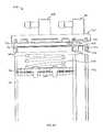
- End cap 350differs from the previously described end cap 304 in that it includes an integrated sound attenuator or muffler. Whereas the embodiment of FIG. 2 includes discreet sound attenuators or mufflers 216 and 218 , the embodiment of end cap 350 integrates a sound attenuator or muffler into its structure.
- end cap 350includes a body having a sieve bed/product tank interface portion 352 .
- Interface portion 352also serves as a base from which muffler portion 354 extends.
- mounting boss 356Also extending from interface portion 352 is a mounting boss 356 .
- a muffler block 358is housed within muffler portion 354 and a perforated exhaust cap 360 closes muffler portion 354 .
- Mounting boss 356accepts a fastener that passes through exhaust cap 360 and muffler block 358 .
- Alternative means for securing these componentscan also be utilized.
- End cap 350further includes an input port 362 and a fitting 364 that may be attached to it.
- End cap 350also includes an input port 365 to the muffler portion 354 .
- Input port 365is connected to muffler portion 354 through passageway 367 . In this manner, gases exhausted from the sieve bed are input through port 365 and passageway 367 into muffler portion 354 . The gases are then exhausted by muffler portion 354 through perforated end cap 360 .
- Sieve bed/product tank interface portion 352is shown having walled structures similar to end cap 304 for accepting a seal member similar to seal member 322 (See FIG. 3F and its accompanying text).
- Muffler portion 354has walls that extend from interface portion 354 so as to form a perimeter bounding space 366 .
- Mounting boss 356also extends from interface portion 352 and resides in space 366 .
- Muffler block 358is porous and includes a bore or hole 368 extending therethrough.
- the bore or hole 368is sized so that mounting boss 356 can be received therein to hold and retain muffler block 358 .
- muffler block 358can be semi-porous having non-porous portions or can be made of any other sound-deadening material.
- Muffler block 358is disposed proximate interface portion 352 within space 366 , though it can sized so as to at least partly fill space 366 . As gases are exhausted, muffler block 358 may be displaced so as to reside more proximate or against perforated cap 360 (see FIG. 3O showing un-displaced position).
- Perforated cap 360includes a plurality of holes for exhausting gases introduced into muffler portion 354 .
- Cap 360includes a base portion having the holes and walls that extend therefrom so as to form a space 370 .
- End cap 360 and its wallsare structured to receive an end section of muffler portion 354 therein. This is accomplished by providing the walls of cap 360 with a shoulder portion for abutting against the end section of the muffler portion 354 .
- a fastenerthen passes through cap 360 and interfaces with boss 356 to hold the two components together.
- Other means of fasteningcan also be used including snap clips, glue, ultrasonic welding, etc.
- FIG. 3Oshows a cross-sectional perspective of end cap 350 illustrating the assembled structure.
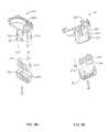
- Compressor assembly 210has frame 406 within which compressor 408 is mounted or suspended.
- Rear housing portion 106has slots 400 and 402 that interface with the compressor assembly 210 .
- Frame 406has tabs such as, for example, tab 404 , which are received in slots 400 and 402 to locate and secure the compressor assembly 210 to the rear housing portion 106 .
- Other means of mounting compressor assembly 210 to rear housing portion 106can also be employed such as, for example, brackets and fasteners.
- FIG. 4Bis an exploded perspective view of the compressor assembly 210 .
- Compressor assembly 210includes compressor 408 , a multi-piece interface bracket having members 420 , 422 , and 424 , frame 406 , and a plurality of suspension members 430 .
- Interface bracket member 420includes a plurality of hook-type portions 428 that couple with apertures 426 in interface bracket members 422 and 424 .
- FIG. 4Cillustrates the interface bracket when members 420 , 422 and 424 are coupled together.
- the interface bracketis coupled or affixed to a body of compressor 408 through appropriate fastening means such as, for example, screws, bolts, clips, or pins.
- suspension members 430include enlarged end portions that are connected together through elongated central portions. Suspension members 430 are resilient in that they can be stretched under tension. In one embodiment, suspension members 430 are formed from an elastomeric material such as, for example, rubber. In other embodiments, suspension members 430 can be made of metal to form resilient springs.
- Frame 406includes a plurality of structural support members generally forming a cage-like structure having a top 414 , bottom 416 , and sides 412 and 418 .
- the corner portions of frame 406include openings or apertures 434 that are used in conjunction with suspension members 430 to mount or suspend compressor 408 within frame 406 as shown in FIG. 4A .
- Interface bracket member 424is shown and includes hook portions 432 that interface with suspension members 430 .
- the enlarged end portions of suspension members 430are inserted within the eye of hook portions 432 and the recesses or openings 434 of frame 406 .
- FIG. 4Dillustrates the suspension or mounting of interface bracket 424 within frame 406
- interface bracket 422is similarly suspended or mounted within the frame 406 thereby suspending or mounting compressor 408 within frame 406 .
- compressor 408is suspended or mounted relative to frame 406 in a manner that isolates the movement or vibration of compressor 408 .
- the movement or vibration of compressor 408is isolated through elastic suspension members 430 .
- Elastic suspension members 430allow compressor 408 to move within frame 406 without translating that movement to frame 406 .
- a total of eight suspension members 430are employed at the corners of frame 406 but this need not to be the case. Any number of suspension members may be used at any location(s) with respect to frame 406 and compressor 408 in a manner that suitably allows compressor 408 to move relative to frame 406 without translating that movement to frame 406 .
- suspension member 436is similar to suspension members 430 in that it structurally incorporates a plurality of suspension members 430 . As shown, suspension member 436 incorporates four individual suspension members 430 . Suspension member 436 further includes connective portions 438 that connects together the individual suspension member portions 430 to form a unitary whole. In other embodiments, suspension member 436 need not be formed as a continuous structure but may also form an open structure such as, for example, by omitting one of the connective portions 438 shown in FIG. 4E . Another configuration that provides for the physical communication of individual suspension members 430 can also be employed.
- Suspension member 436is connected to interface bracket members 422 and 424 in the same manner as described for the individual suspension members of 430 . That is, the enlarged end portions 440 of suspension members 430 are inserted into the eye of hook portions 432 of the interface bracket members and the enlarged end portions 442 are inserted into the openings or recesses 434 of frame 406 . It may be that in some cases suspension member 436 allows for easier assembly of compressor assembly 210 . In the embodiment shown, two suspension members of 436 would be required to replace the eight suspension members 430 shown in FIG. 4B .
- FIG. 4Fillustrates yet another embodiment of compressor assembly 210 having and interface bracket with circular end portions that are suspended within a frame by suspension members 430 .
- compressor assembly 210reduces noise, vibration and vibration induced noise that may emanate from the compressor during operation. Also, compressor assembly is configured that compressor 408 may be mounted within frame 408 according to a plurality of orientations.
- the interface bracket members 420 , 422 and 424 and frame 406can be made of any suitable material including, for example, metal or plastic or combinations thereof.
- a concentratorincludes a variable bleed valve 502 .
- bleed valve 502 and a fixed orifice 514are in series and in pneumatic communication with sieve tanks 300 .
- a flow setting input 504is selected by a user and received by a microprocessor-based controller 506 .
- Controller 506has associated therewith memory and logic for controlling the operation of, for example, the compressor 408 , main valves MV 1 and MV 2 , exhaust valves EV 1 and EV 2 , conserver valve 512 , pressure equalization valve PE and bleed valve 502 . All of these valves are solenoid controlled.
- the compressor 408is run at a variable speed based on the flow setting input 504 .
- low flow settingsallow for the compressor 408 to be run at a slower speed thereby conserving energy.
- the compressor 408can be run at higher speeds for higher flow settings.
- the controller 506may run the compressor 408 at 1,100 revolutions per minute (rpm), 1,500 rpm, 2,050 rpm, 2,450 rpm, and 3,100 rpm with respect to the lowest to highest flow setting inputs 504 .
- rpmrevolutions per minute
- Controller 506also receives input from a pressure sensor 510 .
- the flow setting input 504is received by controller 506 .
- the flow setting input 504may designate a flow rate that the user desires for delivery of the product gas (e.g., oxygen) in a pulsed output mode.
- a plurality of flow input settings 504may include 300 cc/min (e.g., 15 cc/pulse at 20 breaths per minute (bpm)), 460 cc/min (e.g., 23 cc/pulse at 20 bpm), 620 cc/min (e.g., 31 cc/pulse at 20 bpm), 740 cc/min (e.g., 37 cc/pulse at 20 bpm), or 840 cc/min (e.g., 42 cc/pulse at 20 bpm).
- 300 cc/mine.g., 15 cc/pulse at 20 breaths per minute (bpm)
- 460 cc/mine.g
- controller 506appropriately controls the compressor 408 and valves to deliver the desired pulsed output flow of oxygen.
- controller 506appropriately controls the compressor 408 and valves to deliver the desired pulsed output flow of oxygen.
- other flow rate valuesare envisioned and any suitable flow rate value may be implemented.
- the flow setting input 504may designate a flow rate that the user desires for delivery of the product gas in a continuous output mode.
- the concentratoroperates using a pressure swing adsorption (PSA) process.
- PSApressure swing adsorption
- the compressor 408delivers room air, through main valves MV 1 and MV 2 , in an alternate fashion to sieve tanks 300 . While one sieve tank 300 is being filled, the other sieve tank 300 is typically being purged of its contents. As described earlier, each sieve tank 300 is filled within a nitrogen adsorbing material so that nitrogen gas is trapped within the sieve tank 300 and oxygen gas is allowed to pass to the product tank 302 . When a particular sieve tank has reached its adsorption capacity, which can be known by its output pressure, the adsorbed gases, such as nitrogen, must be purged before the sieve tank 300 can be used again.
- Pressure equalization valve PEallows for a more efficient generation of oxygen by equalizing the pressure between the output lines of a sieve tank nearing fill completion and a sieve tank nearing the end of its purge cycle.
- U.S. Pat. Nos. 4,449,990 and 5,906,672which are incorporated herein by reference, further describe the operation of pressure equalization valves.
- the oxygen that is being output by a particular sieve bed 300may be stored in one or both product tanks 302 . Both product tanks 302 are utilized in the embodiment of FIG. 5A .
- controller 506can detect when the sieve tank 300 being pressurized has reached its adsorption capacity via pressure sensor 510 .
- pressure sensor 510provides a signal indicative of pressure at the product tank side of a first check valve 516 that passes oxygen flow from the pressurized sieve tank 300 to interconnected product tanks 300 and a second check valve 516 that blocks oxygen flow from the interconnected product tanks 300 to the other sieve tank 300 while it is being regenerated.
- the signalmay reflect the difference between the pressurized oxygen gas and ambient air.
- the pressure sensor 510may be located anywhere in fluidic communication with the output of the sieve tank 300 being pressurized.
- controller 506shifts the pressurizing sieve tank 300 into a purging or exhausting cycle and shifts the other sieve tank 300 , which is now regenerated, to a pressurizing cycle. This is the basic repetitive, alternating operation of the PSA process.
- the controller 506may shift or alternate cycles for sieve tanks 300 when the pressure sensor 510 detects 9.0 pounds per square inch gauge (psig), 12.5 psig, 16.5 psig, 19.0 psig, and 23.5 psig, with respect to the lowest to highest flow setting inputs 504 .
- psigpounds per square inch gauge
- 12.5 psig12.5 psig
- 16.5 psig16.5 psig
- 19.0 psig19.0 psig
- 23.5 psigpsig
- bleed valve 502has a variable “on delay” before activation to an open or “on” state.
- the variable “on delay”is associated, in one embodiment, with the flow setting input 504 .
- the controller 506may activate the bleed valve 502 after an “on delay” of 3.3 seconds (sec), 3.2 sec, 3.0 sec, 2.9 sec, and 2.9 sec, with respect to the lowest to highest flow setting inputs 504 .
- “on delay” valuesare envisioned and any suitable “on delay” value may be implemented.
- bleed valve 502is de-activated by the controller 506 after the pressurizing sieve bed 300 has reached its capacity in conjunction with the end of the corresponding pressurizing cycle (i.e., the start of the next pressurization cycle for the other sieve tank 300 ).
- bleed valve 502“bleeds” oxygen out of one sieve tank 300 and into the other sieve tank 300 at a flow rate that is restricted by orifice 514 . That is, oxygen is allowed to flow from the sieve tank 300 being pressurized to the sieve tank 300 being exhausted or purged. This oxygen flow assists the exhausting or purging of the sieve tank 300 to expel its captured nitrogen and to regenerate itself for its next pressurization cycle.
- a bleed flow between the sieve tanks 300that can be variably controlled can assist in the efficient purging of the exhausting sieve tank for the corresponding product gas output flow rate of the concentrator at a suitable purity level.
- the higher the value of the flow setting input 504the shorter the “on delay” time (i.e., closed time) and the longer the time that the bleed valve 502 will be open with more bleed flow being sent to the exhausting sieve tank 300 .
- higher pressurization levelsmay be used for the higher values for flow setting inputs 504 .
- the higher pressurization levelsmay require more bleed flow to regenerate the exhausting or purging sieve tank 300 .
- the lower the value of the flow setting input 504the longer the “on delay” time (i.e., closed time) and the shorter the time that the bleed valve 502 will be open. This is because lower pressurization levels may be used for the lower values for flow setting inputs 504 .
- variable “on delay” logicallows for an increased level of system efficiency in terms of maximizing the utilization of the oxygen that is generated by controlling the amount used in the purging of an exhausting sieve tank 300 .
- other variable logicmay be used to vary other control parameters (e.g., bleed flow duration) for the bleed valve 502 for different flow setting inputs 504 .
- the variable logicmay use other sensed parameters (e.g., pressure) to vary the “on delay” or other control parameters for different flow setting inputs 504 .
- the “on delay” time period prior to activation of the bleed valve 502is dependant upon the value for the flow setting input 504 which in turn is based on certain other operating parameters, such as product tank output pressure, sieve tank output pressure, compressor speed, and volumetric capacity of various components.
- the specific “on delay” time period for each flow setting input 504may be determined empirically based on the physical specifications of the concentrator components.
- the “on delay” times for each value for the flow setting input 504are then stored in a look-up table in the memory or logic of controller 506 . Hence, after reading the flow setting input 504 , controller 506 looks up the bleed valve variable “on delay” time from the look-up table stored in its memory or logic.
- the corresponding “on delay” timeis then used to delay activation of the bleed valve 502 from the start of the pressurization cycle for the sieve tank 300 providing the bleed flow.
- the pressurization cyclestarts after the pressure equalization valve PE closes (see timing diagram of FIG. 5B ).
- the bleed valve 502is activated (i.e., opened or “on”) and remains open until the start of the next PSA cycle in which the roles for the two sieve tanks 300 is shifted.
- variable “on delay”may be based at least in part on a minimum “on delay” time. In another embodiment, the variable “on delay” may be based at least in part on one or more other parameters, such as product tank output pressure, sieve tank output pressure, compressor speed, and volumetric capacity of various components in any combination. In still other embodiments, the variable “on delay” may be based at least in part on a minimum “on delay” time in combination with one or more other parameters. For example, after the minimum “on delay” time, activation of the bleed valve 502 may be triggered if the other parameter exceeds a predetermined threshold at that time or any time before the current pressurization cycle is complete.
- activation of the bleed valve 502may be triggered if the other parameter exceeds the predetermined threshold at any time during the pressurization cycle without a minimum “on delay.”
- bleed valve 502may also have a variable “maximum on time” after activation in order to limit the continuous time it remains open or in the “on” state.
- the variable “maximum on time”may be associated with the flow setting input 504 .
- the controller 506may de-activate the bleed valve 502 after a “maximum on time” of 2.2 sec, 2.4 sec, 2.6 sec, 2.8 sec, and 3.0 sec, with respect to the lowest to highest flow setting inputs 504 .
- a “maximum on time”of 2.2 sec, 2.4 sec, 2.6 sec, 2.8 sec, and 3.0 sec, with respect to the lowest to highest flow setting inputs 504 .
- maximum on time2.2 sec, 2.4 sec, 2.6 sec, 2.8 sec, and 3.0 sec
- the bleed valve 502would also be de-activated if the end of the current pressurization is reached before the “maximum on time” expires. Conversely, if the “maximum on time” expires before the end of the current pressurization cycle is reached, the bleed valve 502 could be activated again based on any combination of the “on delay” time or parameter triggers described above. If desired, the bleed valve 502 may also be fixed to provide a continuous bleed or fixed to a predetermined open time that is independent of the flow setting input 504 .
- the “on delay” timemay be set to zero for a particular flow setting input 504 to provide a continuous bleed and the “maximum on time” may be set to zero for a particular flow setting input 504 to inhibit activation of the bleed valve 502 .
- FIG. 5Billustrates one embodiment of a timing diagram for the valves shown in FIG. 5A .
- each pressurization cyclebegins when the pressure equalization valve PE transitions from closed (i.e., off, de-activated) to open (i.e., on, activated).
- the pressure equalization valve PEtransitions from closed (i.e., off, de-activated) to open (i.e., on, activated).
- pressurized oxygen from the first sieve tank 300i.e., associated with main valve MV 1
- the second sieve tank 300i.e., associated with main valve MV 2 .
- Exhaust valve EV 2is de-activated along with this activation of pressure equalization valve PE or shortly thereafter if the pressure equalization valve PE is to be used to assist in purging and regeneration of the second sieve tank 300 .
- main valve MV 1is de-activated and main valve MV 2 is activated to switch inlet air flow generated by the compressor 408 from the first sieve tank 300 to the second sieve tank 300 .
- the pressure equalization valve PEis de-activated shortly after the main valves MV 1 and MV 2 are switched.
- exhaust valve EV 1is activated along with this de-activation of pressure equalization valve PE to permit pressure equalization between the sieve tanks 300 to continue.
- the exhaust valve EV 1could be activated along with de-activation of main valve MV 1 or shortly thereafter and before de-activation of pressure equalization valve PE. This process continues in alternating fashion to provide the PSA process.
- the bleed valve 502may be generally closed or “off” while the pressure equalization valve PE is open or “on,” though this need not necessarily be the case. It can also be seen that the variable “on delay” time for the bleed valve begins when the pressure equalization valve PE transitions from closed or “off” to open or “on,” though this need not be the case as well. It may be beneficial under some circumstances to allow overlapping of the open or “on” states of these valves. In other words, under certain circumstances, both the bleed valve 502 and the pressure equalization PE may be utilized simultaneously or in any combination to provide bleed flow from the pressurizing sieve tank 300 to the other sieve tank 300 for its purging and regeneration.
- FIG. 5Cshows an exemplary path for bleed flow from sieve tank 1 through orifice 1 and sieve tank 2 to an exhaust gas outlet when main valve MV 1 , bleed valve 502 , and exhaust valve EV 2 are activated (i.e., open) and main valve MV 2 and exhaust valve EV 1 are de-activated (i.e., closed).
- FIG. 5Dshows an exemplary alternate path for bleed flow from sieve tank 2 through orifice 1 and sieve tank 1 to the exhaust gas outlet when main valve MV 2 , bleed valve 502 , and exhaust valve EV 1 are activated and main valve MV 1 and exhaust valve EV 2 are de-activated.
- bleed valve 502 and orifice 1may be provided in a single component which may be referred to as a variable restrictor.
- orifice 2may provide a continuous fixed bleed flow in parallel to bleed valve 502 and orifice 1 .
- Orifice 2would establish a minimum bleed flow which could be increased by activation of the bleed valve 502 as described herein.
- a PE valvemay be activated to provide or supplement bleed flow in combination with orifice 2 or the series combination of bleed valve 502 and orifice 1 .
- the controller 506may monitor the PSA shifting time (i.e., pressurization cycle time) to identify alternate modes of operation for certain Earth altitude ranges in which the concentrator is being operated. For example, a low altitude mode may be implemented for operation up to approximately 6,300 feet and a high altitude mode may be implemented for operation above 6,300 feet. Of course, other altitude ranges are envisioned and additional altitude modes may be implemented. PSA shifting time tends to increase at higher altitudes due to lower ambient atmospheric pressures (i.e., thinner air). Certain operating parameters of the concentrator may be adjusted based on a given altitude range in order to improve efficiency and sustain suitable levels of product gas volumetric output, flow rate, and purity.
- PSA shifting timei.e., pressurization cycle time
- a fixed “on delay” for bleed valve 502 based on flow setting input 504may be acceptable in a low altitude mode of operation.
- the higher the altitudethe longer the shift time between pressurization of alternate sieve tanks 300 because the concentrator takes longer and longer to build up to the desired shift pressure.
- the concentratormay shift to a higher altitude mode which may adjust one or more operating parameters (i.e., product tank output pressure, sieve tank output pressure, bleed valve control) to keep the shift time in an optimum range. If a fixed “on delay” for the bleed valve 502 were maintained across a wide altitude range there may be little or no bleed flow at the lower elevations of the altitude range.
- the fixed “on delay”could result in too much bleed flow at higher elevations when the shift time has been significantly stretched out. No bleed flow and too much bleed flow may result in the product gas from the concentrator being outside desired purity levels for operation at the lower and higher elevations of a wide altitude range.
- Suitable shift time thresholdsmay be established for transitioning from low altitude mode to high altitude mode (e.g., approximately 12 seconds) and for transitioning from high altitude mode to low altitude mode (e.g., approximately 5.5 seconds).
- different shift time thresholdscan be established for different flow setting inputs 504 .
- the shift time thresholds for transitioning from low altitude mode to high altitude modecould range between 10.5 and 14 seconds for different flow setting inputs 504 .
- the shift time thresholds for transitioning from high altitude mode to low altitude modecould range between 5.0 and 5.5 seconds for different flow setting inputs 504 .
- the thresholdswill be different and the threshold for transitioning from high altitude mode to low altitude mode will be less than the other threshold to establish a suitable hysteresis.
- transition between altitude modescan be delayed for a fixed time or until the shift times for a predetermined quantity of consecutive pressurization cycles (e.g., three consecutive cycles) indicate that the altitude mode transition is appropriate.
- the bleed valve 502may be controlled in any manner described herein for any altitude mode. Notably, the bleed valve 502 may be controlled differently in different altitude modes. Accordingly, preferred bleed valve control techniques can be implemented based at least in part on altitude mode and transitions in altitude modes can produce corresponding transitions in bleed valve control techniques.
- an “on delay” time associated with activation the bleed valve 502 and the PSA shifting timemay have a generally linear relation encompassing the range of the flow setting inputs 506 .
- the shift timemay be represented by the shift pressure set-point for each flow setting input 506 because the shift time is the time it takes a given sieve tank 300 to reach a pressure related to its full capacity.
- pressure build in the sieve tank 300may be assumed to be linear. This allows a bleed valve activation pressure to be expressed as a ratio of pressure set-point for each flow setting input 506 . The ratio may then be used to determine a threshold pressure value.
- the controller 506activates (i.e., opens) the bleed valve 502 . This may ensure there is at least enough bleed flow to maintain a desired level of purity while also limiting bleed flow to avoid unnecessary loss of oxygen.
- the “on delay” timemay be a non-linear function of the PSA shifting time. Similarly, the function used to determine the “on delay” time may be different for different flow setting inputs 506 in other embodiments.
- HAMhigh altitude mode
- HAM pressure set-pointscan be established using other techniques or other suitable criteria.
- the Ratiomay be a different value or may be replaced by a variable function for any particular flow setting input 506 .
- any suitable technique or criteriamay be used to establish alternate pressure set points for each altitude mode.
- HAM pressure thresholdscan be established using other techniques or other suitable criteria. For example, the constant may be a different value or may be replaced by a variable function for any particular flow setting input 506 . Additionally, where additional altitude modes are implemented any suitable technique or criteria may be used to establish alternate pressure thresholds for each altitude mode.
- the controller 506may utilize a timer function to monitor PSA cycle shift time. This monitored shift time measurement may be compared against shift time ranges stored in non-volatile memory. The controller 506 may use the result of this comparison to determine if the concentrator should be operating in low or high altitude modes. In low altitude mode, for each flow setting input 504 , the concentrator may operate from a fixed pressure value that is stored in non-volatile memory. In high altitude mode, the concentrator may operate from a fixed pressure value for each flow setting input 504 that is based at least in part on the corresponding low altitude fixed pressure value.
- the concentratorin low altitude mode, for each flow setting input 504 , may operate from a fixed “on delay” time for activation of the bleed valve 502 that is stored in non-volatile memory. In high altitude mode, the concentrator may operate from a variable bleed valve activation time that is scaled based on the fixed pressure value for each flow setting input 504 or the monitored PSA cycle shift time. The bleed valve scale factor may be calculated from the fixed pressure value or the monitored PSA cycle shift time.
- logicincludes but is not limited to hardware, firmware, software and/or combinations of each to perform a function(s) or an action(s), and/or to cause a function or action from another component.
- logicmay include a software controlled microprocessor, discrete logic such as an application specific integrated circuit (ASIC), or other programmed logic device.
- ASICapplication specific integrated circuit
- Logicmay also be fully embodied as software.
- Softwareincludes but is not limited to one or more computer readable and/or executable instructions that cause a computer or other electronic device to perform functions, actions, and/or behave in a desire manner.
- the instructionsmay be embodied in various forms such as routines, algorithms, modules or programs including separate applications or code from dynamically linked libraries.
- Softwaremay also be implemented in various forms such as a stand-alone program, a function call, a servlet, an applet, instructions stored in a memory, part of an operating system or another type of executable instructions. It will be appreciated by one of ordinary skill in the art that the form of software is dependent on, for example, requirements of a desired application, the environment it runs on, and/or the desires of a designer/programmer or the like.
- the systems and methods of the present inventioncan be implemented on a variety of platforms including, for example, networked control systems and stand-alone control systems.
- the logic, databases or tables shown and described hereinpreferably reside in or on a computer readable medium such as, for example, a Flash Memory, Read-Only Memory (ROM), Random-Access Memory (RAM), programmable read-only memory (PROM), electrically programmable read-only memory (EPROM), electrically erasable programmable read-only memory (EEPROM), magnetic disk or tape, and optically readable mediums including CD-ROM and DVD-ROM.
- ROMRead-Only Memory
- RAMRandom-Access Memory
- PROMprogrammable read-only memory
- EPROMelectrically programmable read-only memory
- EEPROMelectrically erasable programmable read-only memory
- magnetic disk or tapeand optically readable mediums including CD-ROM and DVD-ROM.
- optically readable mediumsincluding CD-ROM and DVD-ROM.
- the processes and logic described herein
- FIGS. 5E and 5Ffurther illustrate an exemplary embodiment of a valve assembly 214 that includes bleed valve 502 and other components.
- bleed valve 502 , pressure equalization valve PE a conserver valve 512 , fixed orifice 514 , fixed orifice 515 , and check valves 516are mounted or affixed to a block-like manifold body having a plurality of inlets, outlets and inner passageways connecting the inlets, outlets and valves as shown.
- the valve assembly 214results in a space and weight savings that is adaptable to a portable oxygen concentrator and other devices.
- the configurationalso allows for easy service and replacement of the valve assembly 214 should that be necessary.
- the concentratormay include discrete components or any suitable combination of components in one or more valve assemblies.
- bleed valve 502 and fixed orifice 514may be combined in a modular assembly.
- output port 108includes a suitable air filter. Though the oxygen exiting the sieve and product tanks has already been filtered prior to the nitrogen-oxygen separation process, additional filtering may be of assistance to some patients.
- FIG. 6Athe perspective view of one embodiment of output port 108 is shown.
- the output port 108includes a main body 600 , input 602 , extension 604 and output 610 .
- Input 602is configured to meet with pneumatic tubing that delivers oxygen.
- the oxygen received through input 602enters main body 600 .
- Main body 600includes a suitable filter therein such as, for example, a HEPA filter or other suitable filter, for the filtering the oxygen.
- Extension 604includes a key surface 606 and threads 608 .
- the surface 606facilitates a proper orientation of the output port 108 during our assembly with the housing of the oxygen concentrator.
- Threads 608facilitate fastening of the output port 108 to the housing of the oxygen concentrator via a HEX nut or other type of fastener.
- Output 610is configured to mate with tubing that delivers the oxygen to the patient or a medical accessory.
- filter 612occupies a substantial portion of the inner space of main body 600 to filter the oxygen being received through input 602 .
- filter 612has a shape and geometry that complements the shape and geometry of the inner space of main body 600 .
- filter 612is made of a Boro-Silicate Glass microfiber and is hydrophobic. Filter 612 also provides for a filtration efficiency of greater than 99.99% for particle sizes 0.2 micrometers or greater. Other filters having less than all of these properties may be used as well.
- the main body 600is made from a polypropylene material and its inner space provides for an effective filtration area of 3.5 cm 2 .
- the main body materialcan be any suitable material and the filtration area can be made larger or smaller than described.
- output port 108is preferably fabricated by joining two sections that interface in the region of the main body 600 to form the entire output port 108 .
- two sectionsare shown being divided by interface axis 614 extending through main body 600 .
- Filter 612is inserted into one of the sections forming part of the inner space of main body 600 .
- the other sectionwould then be joined through bonding or welding, thereby sealing filter 612 into the inner space of main body 600 .
- the two sectionscan be joined via mating threads or other non-permanent connections that would allow removal and replacement of filter 612 .
- FIG. 7illustrates one embodiment of a process 700 for calibrating pressure sensor 510 within controller 506 .
- the rectangular elementsdenote “processing blocks” and represent computer software instructions or groups of instructions.
- the diamond shaped elementsdenote “decision blocks” and represent computer software instructions or groups of instructions which affect the execution of the computer software instructions represented by the processing blocks.
- the processing and decision blocksrepresent steps performed by functionally equivalent circuits such as a digital signal processor circuit or an application-specific integrated circuit (ASIC).
- ASICapplication-specific integrated circuit
- the flow diagramdoes not depict syntax of any particular programming language. Rather, the flow diagram illustrates the functional information one skilled in the art may use to fabricate circuits or to generate computer software to perform the processing of the system. It should be noted that many routine program elements, such as initialization of loops and variables and the use of temporary variables are not shown. Also the order flow may be changed with the same results being obtained.
- the calibration routinemay be performed by a qualified technician using an adjustable external pressure source.
- a signale.g., analog to digital count (A-D count)
- A-D countanalog to digital count
- controller 506includes as one of its structures an analog-to-digital converter that allows it to read analog signals that emanate from sensors such as pressure and flow sensors.
- the conversion of an analog sensor signal to a digital or binary valueallows the controller to read and use the sensor signal in its processing.
- the first fixed pressure settingcan be any pressure setting including ambient or vacuum.
- a value for the signal read in 702(e.g., corresponding A-D count) is stored in memory.
- the signal (e.g., A-D count) from the pressure sensor 510is read by the controller 506 after the external pressure source is adjusted to a second fixed pressure setting.
- the second fixed pressure settingmay also be a pressure associated with normal operation of the concentrator, such as 20 psig. Similar to the first pressure setting, the second pressure setting can be any pressure setting.
- Block 708stores a value for the signal read in 706 (e.g., corresponding A-D count) in memory.
- the linear extrapolationis then used in block 712 by controller 506 to convert signal values (e.g., A-D counts) from the pressure sensor 510 to psig.
- signal valuese.g., A-D counts
- Xrepresents signal values (e.g., pressure sensor A-D counts or readings)
- Yrepresents pressure in psig.
- any pressure settingcan be used from unit-less or un-calibrated measures of pressure to external calibrated pressure sources.
- FIG. 8illustrates one embodiment of a conserver process 800 for determining a time duration associated with providing a bolus of gas, such as oxygen, to a user of the oxygen concentrator 100 .
- “Bolus,” as used hereinincludes, but is not limited to, a dose or pulse of concentrated product gas, such as oxygen, provided to the user via a suitable user interface, such as a nasal cannula or nasal mask.
- Bolus parameters relating to flow through pneumatic componentsinclude duration and amplitude.
- the duration parameterrelates to activating and de-activating a valve to start and end the bolus.
- the amplitude parameterrelates to flow capacity of the components and pressure of the product gas.
- Oxygen concentrator 100can include, for example, a conserving device for controlling the flow of oxygen to the patient.
- the conserving devicemay be adjustable in relation to one or more parameters to conserve power consumption of the oxygen concentrator 100 while maintaining suitable purity, flow rate, and volume of the product gas.
- the conserving deviceis formed by controller 506 , flow sensor 508 , pressure sensor 510 conserver valve 512 , and fixed orifice 515 (see, FIG. 5A ).
- the conserver process 800represents one embodiment of logic that can reside within controller 506 .
- Controller 506uses, for example, flow sensor 508 to monitor the breathing of a user to determine breathing characteristics (e.g., breath rate, inhalation, exhalation, volume, flow, etc.) of the user.
- breathing characteristicse.g., breath rate, inhalation, exhalation, volume, flow, etc.
- controller 506Upon the start of inhalation (i.e., the end of exhalation), controller 506 is programmed to deliver a bolus of gas, such as oxygen, to the user.
- a bolus of gassuch as oxygen
- the size of the boluscan be fixed or determined at least in part from the patient's breathing characteristics (e.g., breathing rate, duration of inhalation, volume, flow, etc.).
- controller 506controls the on and off state of conserver valve 512 to deliver the proper bolus of gas to the patient.
- a boluscan be provided during the inhalation portion of each breathing cycle.
- the controller 506has detected a trigger associated with the patient's breathing characteristics, determined that a bolus of gas is to be delivered to the patient, and opened or switched the conserver valve 512 to dispense concentrated product gas to the patient.
- a loopnow begins where the controller 506 reads the signal (e.g., A-D count) of the pressure sensor (block 802 ), converts the signal (e.g., A-D count) to psig (block 804 ), and sums the psig values until a pre-determined psig value is reached (block 806 ).
- the pre-determined summation of psig valuesmay relate to a pre-determined volumetric measure of concentrated breathing gas to be provided by the bolus.
- the pre-determined volumetric measure of concentrated breathing gasmay be based at least in part on the patient's breath rate and a desired output volume over a pre-determined time duration (e.g., 300 cc/min).
- a pre-determined time duratione.g. 300 cc/min.
- the physical characteristics of the fixed orifice 515 , the monitored pressure of the product tanks 302 , and the time the conserver valve 512 is activated to provide product gas flowmay be considered by the controller 506 in order to provide the desired volume of product gas in a given bolus.
- the relation of pressure over time for product gas flow through a fixed orificeis a classic integral calculus function. Where the pressure is variable, the time the conserver valve 512 is activated is adjustable in order to provide the desired volume of product gas. Accordingly, the controller 506 may control the conserver valve 512 based at least in part on the monitored pressure.
- the conversion from signal value (e.g., pressure sensor A-D count) to psigis accomplished using the linear extrapolation obtained from FIG. 7 .
- alternative methods of obtaining the psig values from the signal valuee.g., A-D counts
- PSIGrepresents the current psig reading and P represents the current summation of pressures. This formula is derived from the classic integral calculus function defining the relation of pressure over time for product gas flow through a fixed orifice discussed above.
- the signal values (e.g., A-D counts) from the pressure sensor 510can be summed until a pre-determined summation value (e.g., summation A-D count) is reached.
- a pre-determined summation valuee.g., summation A-D count
- the controller 506closes the conserver valve 512 and waits for the next bolus trigger to occur.
- the pre-determined pressure summation thresholdmay relate to a pre-determined volumetric measure of concentrated breathing gas to be provided by the bolus.
- the pre-determined volumetric measure of concentrated breathing gasmay be based at least in part on the patient's breath rate and a desired output volume over a pre-determined time duration (e.g., 840 cc/min).
- the desired output flow rate settinge.g., 840 cc/min
- the desired volume for each bolusmay be 42 cc.
- the desired volume for each bolusmay be 84 cc. Normally, a bolus would be delivered with each patient breath.
- the concentratormay intentionally skip a breath under certain circumstances to ensure that suitable product gas purity levels and system efficiency is achieved. For example, if the breath rate exceeds a predetermined rate (e.g., 36 bpm), the concentrator may not provide a bolus with every breath and may selectively skip breaths in a manner the achieves suitable product gas purity levels and system efficiency.
- a predetermined ratee.g. 36 bpm
- FIG. 9illustrates one embodiment of timing operation of the conserver valve 512 with respect to a breathing characteristic (e.g., inhalation) associated with a user breathing cycle (i.e., BREATH 900 ).
- a breathing characteristice.g., inhalation
- An exemplary breathing cycle 901is shown with an inhalation period followed by an exhalation period.
- Flow sensor 508measures a flow rate associated with the user breathing cycle when the conserver valve 512 is diverting user breathing through the vent port, which is represented by FLOW 902 and an exemplary flow signal 903 corresponding to the exemplary breathing cycle 901 .
- Flow signal 903for example, can represent analog signal levels, digital representations of analog signal levels, or actual flow rate units.
- trigger threshold 904is established for flow signal 903 .
- Trigger threshold 904can, depending on the particular implementation, be a zero-crossing point, offset (positive or negative) from the zero-crossing point, an average flow per cycle, or off-set (positive or negative) from the average flow. In the embodiment shown in FIG. 9 , the trigger threshold 904 is shown as occurring just after the inhalation phase has started. This is an example of a positive offset from the zero-crossing point. In one embodiment, the trigger threshold can be 12 standard cubic centimeters per minute (sccm).
- controller 506opens conserver valve 512 for a time duration long enough to deliver the required size bolus 905 to the user.
- the time duration that the conserver valve 512 remains openmay be determined by the logic of process 800 ( FIG. 8 ). As described above in reference to FIG. 8 , once the summation of pressures reaches the pre-determined summation value, conserver valve 512 is closed 906 by controller 506 . The controller 506 may ignore or otherwise avoid taking action in relation to the trigger threshold 904 at least until a time duration associated with breath rates is exceeded in order to avoid triggering another bolus 905 before the start of the next inhalation.
- the trigger lock-out period 907can be determined as a percentage of a breathing characteristic (e.g., breath rate, breath cycle, exhalation, or other breathing characteristics including flow, flow rate and pressure) for an average person, exemplary person, or a particular person, such as the patient. For example, if a breath rate of 350 milliseconds (msec) is selected, the trigger lock-out period would be some percentage of 350 msec, such as 175 msec.
- This trigger lock-out period 907ensures that the next trigger is not falsely or prematurely initiated until the start of the patient's next inhalation. After expiration of the trigger lock-out period 907 , the next trigger threshold is active.
- the controller 506may also wait for the flow signal to fall below the trigger threshold 904 before enabling the next activation of the conserver valve 512 .
- a bolus 905 of gase.g., oxygen
- the concentratormay intentionally skip a breath under certain circumstances to ensure that suitable product gas purity levels and system efficiency is achieved.
- the conserver valve 512may also be controlled in any manner described herein for any altitude mode. Notably, the conserver valve 512 may be controlled differently in different altitude modes. Accordingly, preferred conserver valve control techniques can be implemented based at least in part on altitude mode and transitions in altitude modes can produce corresponding transitions in conserver valve control techniques.
- the controller 506may automatically adjust operation of the conserver valve 512 to maintain suitable levels of purity, flow rate, and volume for the product gas as elevation changes. If not adjusted, for example, the conserver valve 512 may stay activated longer as the PSA cycle shift time increases in relation to higher elevations. This may result in larger bolus volumes than necessary and higher product gas outputs than desired.
- the concentratormay operate using a low altitude fixed time duration for activation of the conserver valve 512 for a given flow setting input 504 .
- the low altitude fixed time durationmay be different for different flow setting inputs 504 .
- Each low altitude fixed time durationmay be a function of PSA cycle shift time and decay in pressure of the concentrated product gas associated with the shifting. These low altitude fixed time durations may be stored in non-volatile memory.
- the concentratormay operate using a high altitude fixed time duration for activation of the conserver valve 512 at a given flow setting input 504 .
- the high altitude fixed time durationmay be different for different flow setting inputs 504 .
- Each high altitude fixed time durationmay be a function of the low altitude fixed time duration for the corresponding flow setting input 504 .
- the functional relationship between the low and high altitude fixed time durationsmay be different for different flow setting inputs 504 .
- the algorithm defining the function at a given flow setting input 504may be different from the algorithm defining the function at a different flow setting input 504 .
- These high altitude fixed time durationsmay be stored in non-volatile memory.
- values for certain parameters of the functions (i.e., algorithms), particularly parameters that vary for different flow setting inputs 504may be stored in non-volatile memory.
- a product gas concentrator 10may include an input device 12 , a product gas source 14 , a pressure sensor 16 , a conserver valve 18 , and a controller 20 .
- the input device 12may be used to select a first desired output flow rate setting for the concentrated product gas.
- the product gas source 14may provide the concentrated product gas for dispensing.
- the pressure sensor 16may monitor a pressure of the concentrated product gas.
- the conserver valve 18may include an output connection, a vent connection, and a gas connection.
- the output connectionmay be associated with a user 22 .
- the vent connectionmay be associated with a vent port 24 .
- the gas connectionmay be associated with the concentrated product gas.
- the output connectionmay be switched from the vent connection to the gas connection and vice versa.
- the controlleris in operative communication with the input device 12 and pressure sensor 16 and may selectively switch the conserver valve 18 to selectively dispense the concentrated product gas based at least in part on the selected output flow rate setting and monitored pressure.
- the pressure sensor 16may monitor pressure between the conserver valve 18 and the product gas source 14 .
- the pressure sensor 16may monitor pressure in another suitable location.
- the controller 20may store a first pressure value based at least in part on the corresponding monitored pressure.
- the controller 20may also store a second pressure value based at least in part on the corresponding monitored pressure after the input device 12 is used to select a second desired output flow rate setting.
- the controller 20may determine an intermediate pressure value between the first and second pressure values based at least in part on a linear relation between the first and second pressure values and the monitored pressure.
- the product gas concentrator 10may also include a flow sensor 26 .
- the flow sensor 26may monitor a flow indicative of a breathing cycle for the user 22 .
- the controller 20may be in operative communication with the flow sensor 26 .
- the flow sensor 26may monitor flow between the conserver valve 18 and the vent port 24 .
- the controller 20may determine a breathing characteristic of the user 22 based at least in part on the monitored flow.
- the controller 20may selectively switch the conserver valve 18 based at least in part on the determined breathing characteristic.
- the flow sensor 26may monitor a flow indicative of a breathing cycle for the user 22 in another suitable location.
- the controller 20may determine a start time for dispensing a bolus of concentrated product gas to the user 22 via the conserver valve 18 based at least in part on a relation between the determined breathing characteristic and a trigger threshold indicative of inhalation.
- the controller 20may determine a pressure summation threshold based at least in part on the selected output flow rate setting.
- the controller 20may also determine the start time for dispensing the bolus of concentrated product gas based at least in part on expiration of a lock-out time associated with a previous bolus.
- the controller 20may determine a time duration for dispensing the bolus of concentrated product gas based at least in part on a relation between the monitored pressure and the pressure summation threshold.
- an exemplary embodiment of a process 50 for providing a concentrated product gasmay begin at 52 , where a first desired output flow rate setting for the concentrated product gas may be selected.
- a product gas source for dispensing the concentrated product gasmay be provided ( 54 ).
- a pressure of the concentrated product gasmay be monitored.
- an output connection associated with a usermay be selectively switched from a vent connection associated with a vent port to a gas connection associated with the concentrated product gas and vice versa to selectively dispense the concentrated product gas based at least in part on the selected output flow rate setting and monitored pressure ( 58 ).
- the process 50may also include storing a first pressure value based at least in part on the monitored pressure, selecting a second desired output flow rate setting for the concentrated product gas, storing a second pressure value based at least in part on the monitored pressure, and determining an intermediate pressure value between the first and second pressure values based at least in part on a linear relation between the first and second pressure values.
- the process 50may also include monitoring a flow indicative of a breathing cycle for the user and determining a breathing characteristic of the user based at least in part on the monitored flow.
- the selective switching in 58may be based at least in part on the monitored breathing characteristic.
- the process 50may further include determining a start time for dispensing a bolus of concentrated product gas to the user via the output connection based at least in part on a relation between the monitored breathing characteristic and a trigger threshold indicative of inhalation.
- the process 50may also include determining the start time for dispensing the bolus of concentrated product gas based at least in part on expiration of a lock-out time associated with a previous bolus.
- the process 50may also include determining a pressure summation threshold based at least in part on the selected output flow rate setting and determining a time duration for dispensing the bolus of concentrated product gas based at least in part on a relation between the monitored pressure and the pressure summation threshold.
Landscapes
- Health & Medical Sciences (AREA)
- Engineering & Computer Science (AREA)
- Emergency Medicine (AREA)
- Chemical & Material Sciences (AREA)
- Pulmonology (AREA)
- General Health & Medical Sciences (AREA)
- Hematology (AREA)
- Veterinary Medicine (AREA)
- Public Health (AREA)
- Anesthesiology (AREA)
- Biomedical Technology (AREA)
- Heart & Thoracic Surgery (AREA)
- Animal Behavior & Ethology (AREA)
- Life Sciences & Earth Sciences (AREA)
- Chemical Kinetics & Catalysis (AREA)
- Analytical Chemistry (AREA)
- General Chemical & Material Sciences (AREA)
- Oil, Petroleum & Natural Gas (AREA)
- Otolaryngology (AREA)
- Separation Of Gases By Adsorption (AREA)
Abstract
Description
HAM Pressure Set-Point=LAM Pressure Set-Point*Ratio (1),
where the Ratio may be 0.875 for all
HAM Pressure Threshold=HAM Pressure Set-Point*Ratio (2),
where the Ratio may be: i) 0.55 for the lowest
| HAM Pressure | ||||
| LAM Pressure | HAM Pressure | Threshold for | ||
| Flow | Set-Point | Set-Point | Bleed Valve | |
| Setting | (psig) | (psig) | Ratio | Activation (psig) |
| 1 | 9.0 | 7.88 | .55 | 4.33 |
| 2 | 12.5 | 10.94 | .60 | 6.56 |
| 3 | 16.5 | 14.44 | .65 | 9.38 |
| 4 | 19.0 | 16.63 | .70 | 11.64 |
| 5 | 23.5 | 20.56 | .75 | 15.42 |
| HAM Pressure | ||||
| LAM Pressure | HAM Pressure | Threshold for | ||
| Flow | Set-Point | Set-Point | Bleed Valve | |
| Setting | (psig) | (psig) | Ratio | Activation (psig) |
| 1 | 9.0 | 7.88 | .90 | 7.09 |
| 2 | 12.5 | 10.94 | .90 | 9.84 |
| 3 | 16.5 | 14.44 | .90 | 12.99 |
| 4 | 19.0 | 16.63 | .90 | 14.96 |
| 5 | 23.5 | 20.56 | .90 | 18.51 |
Claims (20)
Priority Applications (2)
| Application Number | Priority Date | Filing Date | Title |
|---|---|---|---|
| US14/202,536US9375674B2 (en) | 2005-10-25 | 2014-03-10 | Product gas concentrator and method associated therewith |
| US15/193,521US10010696B2 (en) | 2005-10-25 | 2016-06-27 | Product gas concentrator and method associated therewith |
Applications Claiming Priority (6)
| Application Number | Priority Date | Filing Date | Title |
|---|---|---|---|
| US11/258,480US7455717B2 (en) | 2004-10-25 | 2005-10-25 | Apparatus and method of providing concentrated product gas |
| US11/522,683US7722700B2 (en) | 2006-09-18 | 2006-09-18 | Apparatus and method of providing concentrated product gas |
| US91305607P | 2007-04-20 | 2007-04-20 | |
| US96827307P | 2007-08-27 | 2007-08-27 | |
| US12/106,861US8668767B2 (en) | 2007-04-20 | 2008-04-21 | Product gas concentrator and method associated therewith |
| US14/202,536US9375674B2 (en) | 2005-10-25 | 2014-03-10 | Product gas concentrator and method associated therewith |
Related Parent Applications (1)
| Application Number | Title | Priority Date | Filing Date |
|---|---|---|---|
| US12/106,861DivisionUS8668767B2 (en) | 2005-10-25 | 2008-04-21 | Product gas concentrator and method associated therewith |
Related Child Applications (1)
| Application Number | Title | Priority Date | Filing Date |
|---|---|---|---|
| US15/193,521ContinuationUS10010696B2 (en) | 2005-10-25 | 2016-06-27 | Product gas concentrator and method associated therewith |
Publications (2)
| Publication Number | Publication Date |
|---|---|
| US20140251130A1 US20140251130A1 (en) | 2014-09-11 |
| US9375674B2true US9375674B2 (en) | 2016-06-28 |
Family
ID=39870915
Family Applications (3)
| Application Number | Title | Priority Date | Filing Date |
|---|---|---|---|
| US12/106,861Active2029-11-22US8668767B2 (en) | 2005-10-25 | 2008-04-21 | Product gas concentrator and method associated therewith |
| US14/202,536Active2029-02-13US9375674B2 (en) | 2005-10-25 | 2014-03-10 | Product gas concentrator and method associated therewith |
| US15/193,521ActiveUS10010696B2 (en) | 2005-10-25 | 2016-06-27 | Product gas concentrator and method associated therewith |
Family Applications Before (1)
| Application Number | Title | Priority Date | Filing Date |
|---|---|---|---|
| US12/106,861Active2029-11-22US8668767B2 (en) | 2005-10-25 | 2008-04-21 | Product gas concentrator and method associated therewith |
Family Applications After (1)
| Application Number | Title | Priority Date | Filing Date |
|---|---|---|---|
| US15/193,521ActiveUS10010696B2 (en) | 2005-10-25 | 2016-06-27 | Product gas concentrator and method associated therewith |
Country Status (7)
| Country | Link |
|---|---|
| US (3) | US8668767B2 (en) |
| EP (2) | EP2144687B1 (en) |
| CN (2) | CN103657334B (en) |
| AU (1) | AU2008242596C1 (en) |
| CA (2) | CA2684871C (en) |
| NZ (3) | NZ580515A (en) |
| WO (1) | WO2008131338A1 (en) |
Cited By (3)
| Publication number | Priority date | Publication date | Assignee | Title |
|---|---|---|---|---|
| US11247008B1 (en) | 2020-08-05 | 2022-02-15 | Effortless Oxygen, Llc | Flow triggered gas delivery |
| US11318276B2 (en) | 2020-08-05 | 2022-05-03 | Effortless Oxygen, Llc | Flow triggered gas delivery |
| US11420007B2 (en) | 2020-08-05 | 2022-08-23 | Effortless Oxygen, Llc | Flow triggered gas delivery |
Families Citing this family (49)
| Publication number | Priority date | Publication date | Assignee | Title |
|---|---|---|---|---|
| US7455717B2 (en) | 2004-10-25 | 2008-11-25 | Invacare Corporation | Apparatus and method of providing concentrated product gas |
| WO2008131338A1 (en) | 2007-04-20 | 2008-10-30 | Invacare Corporation | Product gas concentrator and method associated therewith |
| US9120050B2 (en)* | 2008-04-21 | 2015-09-01 | Invacare Corporation | Product gas concentrator utilizing vacuum swing adsorption and method associated therewith |
| MX2014002846A (en) | 2011-09-13 | 2014-06-05 | Koninkl Philips Nv | Portable oxygen concentrator with integrated manifold. |
| US9266053B2 (en) | 2012-06-18 | 2016-02-23 | Invacare Corporation | System and method for concentrating gas |
| US9067174B2 (en) | 2012-03-09 | 2015-06-30 | Invacare Corporation | System and method for concentrating gas |
| EP2822671B1 (en) | 2012-03-09 | 2018-10-03 | Invacare Corporation | System and method for concentrating gas by adsorption |
| ITMI20122038A1 (en)* | 2012-11-29 | 2014-05-30 | Marco Pruneri | MACHINE STRUCTURE FOR GAS PRODUCTION |
| US9649589B2 (en) | 2013-02-21 | 2017-05-16 | Lehigh University | Oxygen concentrator system and method |
| USD700701S1 (en)* | 2013-03-08 | 2014-03-04 | Inogen, Inc. | Oxygen concentrator |
| US9061238B2 (en) | 2013-03-15 | 2015-06-23 | Invacare Corporation | Gas concentrator |
| US10004869B2 (en)* | 2013-12-27 | 2018-06-26 | Inogen, Inc. | Gas concentrator with removable cartridge adsorbent beds |
| WO2016057616A1 (en)* | 2014-10-07 | 2016-04-14 | Incoba, Llc | Method and system of sensing airflow and delivering therapeutic gas to a patient |
| US11247015B2 (en) | 2015-03-24 | 2022-02-15 | Ventec Life Systems, Inc. | Ventilator with integrated oxygen production |
| US10245406B2 (en) | 2015-03-24 | 2019-04-02 | Ventec Life Systems, Inc. | Ventilator with integrated oxygen production |
| KR102585024B1 (en) | 2016-01-05 | 2023-10-05 | 엘지전자 주식회사 | Clothes treatment apparatus having the heat pump module |
| FR3052085B1 (en)* | 2016-06-02 | 2020-12-25 | Air Liquide | AIR SEPARATION DEVICE AND GAS GENERATION DEVICE INCLUDING SUCH A DEVICE |
| US10773049B2 (en) | 2016-06-21 | 2020-09-15 | Ventec Life Systems, Inc. | Cough-assist systems with humidifier bypass |
| US20210275771A1 (en)* | 2016-07-08 | 2021-09-09 | Oxigear Corporation | Apparatus and methods for cleaning and oxygen-enriching air |
| US10864127B1 (en) | 2017-05-09 | 2020-12-15 | Pride Mobility Products Corporation | System and method for correcting steering of a vehicle |
| US11446457B2 (en)* | 2017-08-25 | 2022-09-20 | ResMed Pty Ltd | Methods and apparatus for treating a respiratory disorder |
| WO2019221852A1 (en) | 2018-05-13 | 2019-11-21 | Ahmad Samir Saleh | Portable medical ventilator system using portable oxygen concentrators |
| US20210346634A1 (en)* | 2018-08-23 | 2021-11-11 | ResMed Pty Ltd | Methods and apparatus for controlling respiratory therapy with supplementary oxygen |
| CN111617561B (en)* | 2019-02-28 | 2021-05-18 | 宁波方太厨具有限公司 | Filtering device replacement, cleaning and detection method based on equipment parameter detection |
| US20200306683A1 (en) | 2019-04-01 | 2020-10-01 | Inogen, Inc. | Compact portable oxygen concentrator |
| AU2020283463A1 (en) | 2019-05-28 | 2022-01-06 | Ventec Life Systems, Inc. | System and method for concentrating gas |
| US20220379066A1 (en)* | 2019-11-07 | 2022-12-01 | ResMed Asia Pte. Ltd. | Methods and apparatus for control of oxygen concentrator |
| US11085016B1 (en) | 2020-01-20 | 2021-08-10 | Chio Kang Medical, Inc. | Method for screening bacteria capable of degrading ethylene oxide |
| US11130939B2 (en) | 2020-01-20 | 2021-09-28 | Chio Kang Medical, Inc. | Bacteria for degrading ethylene oxide and uses thereof |
| US11220667B2 (en) | 2020-01-20 | 2022-01-11 | Chio Kang Medical, Inc. | Bacteria for degrading ethylene oxide and applications thereof |
| US11124438B2 (en) | 2020-01-20 | 2021-09-21 | Chio Kang Medical, Inc. | Alcaligenes faecalis for degrading ethylene oxide |
| US11130095B1 (en) | 2020-03-18 | 2021-09-28 | Chio Kang Medical, Inc. | Sterilization exhaust gas treating system and method for treating ethylene oxide-containing sterilization exhaust gas by using the same |
| WO2021184605A1 (en) | 2020-03-18 | 2021-09-23 | Qiaokang Biotech (Guangdong) Co., LTD. | Microbiological treatment system for ethylene oxide exhaust gas |
| US11103829B1 (en) | 2020-03-18 | 2021-08-31 | Chio Kang Medical, Inc. | Systems and methods for treating ethylene oxide waste gas |
| US11123680B1 (en)* | 2020-03-18 | 2021-09-21 | Chio Kang Medical, Inc. | Devices, systems, and methods for treating ethylene oxide waste gas |
| US11125498B1 (en) | 2020-03-18 | 2021-09-21 | Chio Kang Medical, Inc. | Gas liquefaction separator, gas liquefaction recovery system, and method for separating and recovering ethylene oxide |
| US11110390B1 (en) | 2020-03-18 | 2021-09-07 | Chio Kang Medical, Inc. | Systems and methods for treating sterilization exhaust gas containing ethylene oxide |
| US11129914B1 (en) | 2020-03-19 | 2021-09-28 | Chio Kang Medical, Inc. | Ethylene oxide adsorption tower and recovery system, and method for recovering ethylene oxide |
| US20210299378A1 (en)* | 2020-03-31 | 2021-09-30 | Air Boost, LLC | Emergency ventilator |
| WO2022000464A1 (en) | 2020-07-03 | 2022-01-06 | Qiaokang Biotech (Guangdong) Co., LTD. | Mobile pretreatment apparatus and an operating method thereof, and a mobile analysis apparatus and an operating method thereof |
| WO2022000463A1 (en) | 2020-07-03 | 2022-01-06 | Qiaokang Biotech (Guangdong) Co., LTD. | Mobile sterilization system, mobile execution system, and mobile analysis system |
| JP7645570B2 (en) | 2020-07-16 | 2025-03-14 | ベンテック ライフ システムズ, インコーポレイテッド | Systems and methods for concentrating gases - Patents.com |
| CA3189540A1 (en)* | 2020-07-16 | 2022-01-20 | Invacare Corporation | System and method for concentrating gas |
| WO2022015908A1 (en) | 2020-07-16 | 2022-01-20 | Invacare Corporation | System and method for concentrating gas |
| CA3189544A1 (en)* | 2020-07-16 | 2022-01-20 | Invacare Corporation | System and method for managing medical devices |
| CN116648278A (en) | 2020-07-16 | 2023-08-25 | 英瓦卡尔公司 | System and method for concentrating gas |
| US12347555B2 (en) | 2021-07-15 | 2025-07-01 | Ventec Life Systems, Inc. | System and method for medical device communication |
| US12415051B2 (en) | 2023-09-07 | 2025-09-16 | Roam Technologies Pty Ltd. | Oxygen concentrator |
| USD1081971S1 (en)* | 2024-10-17 | 2025-07-01 | Shanghai Qingjiang E-commerce Co., Ltd. | Oxygen concentrator |
Citations (67)
| Publication number | Priority date | Publication date | Assignee | Title |
|---|---|---|---|---|
| GB1270296A (en) | 1968-05-07 | 1972-04-12 | Union Carbide Corp | Adsorption process |
| US4127395A (en) | 1976-10-18 | 1978-11-28 | Pall Corporation | Adsorbent fractionator with fail-safe automatic cycle control and process |
| US4144037A (en) | 1976-02-27 | 1979-03-13 | Boc Limited | Gas separation |
| US4247311A (en) | 1978-10-26 | 1981-01-27 | Pall Corporation | Downflow or upflow adsorbent fractionator flow control system |
| US4449990A (en) | 1982-09-10 | 1984-05-22 | Invacare Respiratory Corp. | Method and apparatus for fractioning oxygen |
| US4561287A (en) | 1982-07-09 | 1985-12-31 | Hudson Oxygen Therapy Sales Company | Oxygen concentrator |
| US4575042A (en) | 1984-08-17 | 1986-03-11 | Associates Of Dallas | Pneumatically amplified conservation valve |
| US4648888A (en) | 1982-07-09 | 1987-03-10 | Hudson Oxygen Therapy Sales Co. | Oxygen concentrator |
| US4826510A (en) | 1988-01-13 | 1989-05-02 | The John Bunn Company | Portable low profile DC oxygen concentrator |
| US4832711A (en) | 1982-02-25 | 1989-05-23 | Pall Corporation | Adsorbent fractionator with automatic temperature-sensing cycle control and process |
| US4932402A (en) | 1986-04-11 | 1990-06-12 | Puritan-Bennett Corporation | Inspiration oxygen saver |
| US4971609A (en) | 1990-02-05 | 1990-11-20 | Pawlos Robert A | Portable oxygen concentrator |
| EP0420620A2 (en) | 1989-09-26 | 1991-04-03 | Infusaid Inc. | Pressure regulator for implantable pump |
| US5099837A (en) | 1990-09-28 | 1992-03-31 | Russel Sr Larry L | Inhalation-based control of medical gas |
| US5258056A (en) | 1991-09-27 | 1993-11-02 | The Boc Group, Inc. | PSA system with product turndown and purity control |
| US5474595A (en) | 1994-04-25 | 1995-12-12 | Airsep Corporation | Capacity control system for pressure swing adsorption apparatus and associated method |
| DE29605889U1 (en) | 1996-03-29 | 1996-06-20 | Kröber Medizintechnik GmbH, 56332 Dieblich | Device for generating oxygen-enriched air |
| US5593478A (en) | 1994-09-28 | 1997-01-14 | Sequal Technologies, Inc. | Fluid fractionator |
| US5626131A (en) | 1995-06-07 | 1997-05-06 | Salter Labs | Method for intermittent gas-insufflation |
| US5720276A (en) | 1994-10-25 | 1998-02-24 | Teijin Limited | Apparatus for supplying a respiratory gas to a patient |
| US5785681A (en) | 1997-02-25 | 1998-07-28 | Minimed Inc. | Flow rate controller for a medication infusion pump |
| WO1998056488A1 (en) | 1997-06-12 | 1998-12-17 | Invacare Corporation | Closed-loop feedback control for oxygen concentrator |
| WO1998057165A1 (en) | 1997-06-12 | 1998-12-17 | Invacare Corporation | Acoustic gas concentration sensor and control for oxygen concentrator |
| US5988165A (en) | 1997-10-01 | 1999-11-23 | Invacare Corporation | Apparatus and method for forming oxygen-enriched gas and compression thereof for high-pressure mobile storage utilization |
| US6051051A (en) | 1996-11-15 | 2000-04-18 | Uop Llc | Binder-free molecular sieve zeolite granules which contain zeolites of the type lithium zeolite A and lithium zeolite X |
| US6106245A (en) | 1997-10-09 | 2000-08-22 | Honeywell | Low cost, high pumping rate electrostatically actuated mesopump |
| US20020053286A1 (en) | 1999-05-12 | 2002-05-09 | Respironics, Inc. | Total delivery oxygen concentration system |
| US6427690B1 (en) | 1998-10-21 | 2002-08-06 | Airsep Corporation | Combined oxygen regulator and conservation device |
| US6517610B1 (en) | 2001-11-13 | 2003-02-11 | The United States Of America As Represented By The Secretary Of The Navy | Microelectromechanical gas concentrator |
| US6520176B1 (en) | 2000-05-25 | 2003-02-18 | L'air Liquide, Societe Anonyme A Directoire Et Conseil De Surveillance Pour L'etude Et L'exploitation Des Procedes Georges Claude | Portable oxygen concentrator |
| US6561187B2 (en) | 1997-07-25 | 2003-05-13 | Minnesota Innovative Technologies & Instruments Corporation | Control of supplemental respiratory oxygen |
| US20030180164A1 (en) | 2002-03-13 | 2003-09-25 | Teragenics, Inc. | Electromagnetic pump |
| US6629525B2 (en) | 2000-08-03 | 2003-10-07 | Sequal Technologies, Inc. | Portable oxygen concentration system and method of using the same |
| US20030215342A1 (en) | 2002-03-27 | 2003-11-20 | Kusunoki Higashino | Fluid transferring system and micropump suitable therefor |
| US20030231967A1 (en) | 2002-05-13 | 2003-12-18 | Khalil Najafi | Micropump assembly for a microgas chromatograph and the like |
| US6691702B2 (en) | 2000-08-03 | 2004-02-17 | Sequal Technologies, Inc. | Portable oxygen concentration system and method of using the same |
| US20040079359A1 (en) | 2002-10-24 | 2004-04-29 | Aylsworth Alonzo C. | Method and system for delivery of therapeutic gas to a patient and for filling a cylinder |
| US6764534B2 (en) | 2002-01-31 | 2004-07-20 | Airsep Corporation | Portable oxygen concentrator |
| US6837244B2 (en) | 2000-09-21 | 2005-01-04 | Ngk Spark Plug Co., Ltd. | Oxygen enriching apparatus, controller for the oxygen enriching apparatus, and recording medium for the controller |
| US6878186B2 (en) | 2003-09-09 | 2005-04-12 | David Lloyd Neary | Pure vacuum swing adsorption system and apparatus |
| US6962654B2 (en) | 2001-06-12 | 2005-11-08 | Hydrotreat, Inc. | Methods and apparatus for supplying high concentrations of dissolved oxygen and ozone for chemical and biological processes |
| US20060086251A1 (en) | 2004-10-25 | 2006-04-27 | Invacare Corporation | Apparatus and method of providing concentrated product gas |
| EP1661596A2 (en) | 2003-08-26 | 2006-05-31 | Teijin Pharma Limited | Oxygen-concentrating device |
| US20060174872A1 (en) | 2005-02-09 | 2006-08-10 | Vbox, Incorporated | Method and apparatus for controlling the purity of oxygen produced by an oxygen concentrator |
| WO2006092635A1 (en) | 2005-03-02 | 2006-09-08 | Concept 2 Manufacture Design Ocd Ltd | Conserving device for breathable gas |
| US20060219245A1 (en) | 2005-04-01 | 2006-10-05 | Holder Gary N | Gas conserving device |
| US20060230929A1 (en)* | 2005-04-05 | 2006-10-19 | Bliss Peter L | Portable oxygen concentrator |
| US7306657B2 (en) | 2003-10-28 | 2007-12-11 | Ngk Spark Plug Co., Ltd. | Oxygen concentrating apparatus |
| US20080066616A1 (en) | 2006-09-18 | 2008-03-20 | Thomas Sprinkle | Apparatus and method of providing concentrated product gas |
| US7393382B2 (en) | 2004-12-20 | 2008-07-01 | Idatech Llc | Temperature-based breakthrough detection and pressure swing adsorption systems and fuel processing systems including the same |
| US20080257145A1 (en) | 2007-04-20 | 2008-10-23 | Invacare Corporation | Product gas concentrator and method associated therewith |
| US7445663B1 (en) | 2004-10-21 | 2008-11-04 | Sunrise Medical Hhg Inc. | Energy efficient oxygen concentrator |
| DE102007021564A1 (en) | 2007-05-08 | 2008-11-20 | Linde Ag | Component e.g. plate-type heat exchanger, temperature measuring method for petrochemical industry or petrochemical system, involves evaluating optical signals of optical fiber present inside component |
| US20090211448A1 (en) | 2008-02-21 | 2009-08-27 | Mcclain Michael S | Oxygen concentrator water separating system |
| US7604005B2 (en) | 2005-02-09 | 2009-10-20 | Vbox Incorporated | Adsorbent cartridge for oxygen concentrator |
| US20100071698A1 (en) | 2007-05-07 | 2010-03-25 | Teijin Pharma Limited | Oxygen concentrator |
| US7686870B1 (en) | 2005-12-29 | 2010-03-30 | Inogen, Inc. | Expandable product rate portable gas fractionalization system |
| US20100095841A1 (en) | 2008-10-20 | 2010-04-22 | Pacific Consolidated Industries, Inc. | VSA gas concentrator using a reversing blower |
| US20100114218A1 (en) | 2004-09-24 | 2010-05-06 | Roger Lee Heath | Resuscitation and life support system, method and apparatus |
| US7766010B2 (en) | 2005-02-09 | 2010-08-03 | Vbox, Incorporated | Method of controlling the rate of oxygen produced by an oxygen concentrator |
| US20100242734A1 (en) | 2007-11-15 | 2010-09-30 | Teijin Pharma Limited | Oxygen concentrator |
| US7875105B2 (en) | 2006-08-08 | 2011-01-25 | Invacare Corporation | Oxygen concentrator having structural sieve beds |
| US20110017216A1 (en) | 2009-07-22 | 2011-01-27 | Van Brunt Nicholas P | Method of separating and distributing oxygen |
| US8062003B2 (en) | 2005-09-21 | 2011-11-22 | Invacare Corporation | System and method for providing oxygen |
| US20110315140A1 (en) | 2010-06-29 | 2011-12-29 | Precision Medical, Inc. | Portable oxygen concentrator |
| US8262771B2 (en) | 2006-10-31 | 2012-09-11 | Osaka Gas Co., Ltd. | Flammable gas concentration device and flammable gas concentration method |
| WO2013134645A1 (en) | 2012-03-09 | 2013-09-12 | Invacare Corporation | System and method for concentrating gas by adsorption |
Family Cites Families (6)
| Publication number | Priority date | Publication date | Assignee | Title |
|---|---|---|---|---|
| FI76003C (en)* | 1986-02-12 | 1988-09-09 | A Happi Oy | Gas amplification method and apparatus |
| AU2001279527A1 (en)* | 2000-08-02 | 2002-02-13 | Wearair Oxygen Inc. | Miniaturized wearable oxygen concentrator |
| US6712876B2 (en) | 2002-08-27 | 2004-03-30 | Litton Systems, Inc. | Oxygen concentrator system with altitude compensation |
| KR100476161B1 (en)* | 2003-02-18 | 2005-03-15 | 엘지전자 주식회사 | Gas concentrator |
| CN1697682A (en)* | 2003-04-09 | 2005-11-16 | 株式会社Jej | gas concentrator |
| US7013898B2 (en)* | 2004-07-09 | 2006-03-21 | Praxair Technology, Inc. | Nasal pressure sensor oxygen therapy device |
- 2008
- 2008-04-21WOPCT/US2008/061022patent/WO2008131338A1/enactiveApplication Filing
- 2008-04-21NZNZ580515Apatent/NZ580515A/enunknown
- 2008-04-21CNCN201310563818.XApatent/CN103657334B/ennot_activeExpired - Fee Related
- 2008-04-21EPEP08746446.7Apatent/EP2144687B1/enactiveActive
- 2008-04-21USUS12/106,861patent/US8668767B2/enactiveActive
- 2008-04-21NZNZ603120Apatent/NZ603120A/enunknown
- 2008-04-21NZNZ619142Apatent/NZ619142A/enunknown
- 2008-04-21EPEP15170789.0Apatent/EP2977092B1/enactiveActive
- 2008-04-21CNCN2008800211486Apatent/CN101687134B/ennot_activeExpired - Fee Related
- 2008-04-21CACA2684871Apatent/CA2684871C/enactiveActive
- 2008-04-21AUAU2008242596Apatent/AU2008242596C1/enactiveActive
- 2008-04-21CACA2871228Apatent/CA2871228C/enactiveActive
- 2014
- 2014-03-10USUS14/202,536patent/US9375674B2/enactiveActive
- 2016
- 2016-06-27USUS15/193,521patent/US10010696B2/enactiveActive
Patent Citations (80)
| Publication number | Priority date | Publication date | Assignee | Title |
|---|---|---|---|---|
| GB1270296A (en) | 1968-05-07 | 1972-04-12 | Union Carbide Corp | Adsorption process |
| US4144037A (en) | 1976-02-27 | 1979-03-13 | Boc Limited | Gas separation |
| US4127395A (en) | 1976-10-18 | 1978-11-28 | Pall Corporation | Adsorbent fractionator with fail-safe automatic cycle control and process |
| US4247311A (en) | 1978-10-26 | 1981-01-27 | Pall Corporation | Downflow or upflow adsorbent fractionator flow control system |
| US4832711A (en) | 1982-02-25 | 1989-05-23 | Pall Corporation | Adsorbent fractionator with automatic temperature-sensing cycle control and process |
| US4561287A (en) | 1982-07-09 | 1985-12-31 | Hudson Oxygen Therapy Sales Company | Oxygen concentrator |
| US4648888A (en) | 1982-07-09 | 1987-03-10 | Hudson Oxygen Therapy Sales Co. | Oxygen concentrator |
| US4449990A (en) | 1982-09-10 | 1984-05-22 | Invacare Respiratory Corp. | Method and apparatus for fractioning oxygen |
| US4575042A (en) | 1984-08-17 | 1986-03-11 | Associates Of Dallas | Pneumatically amplified conservation valve |
| US4932402A (en) | 1986-04-11 | 1990-06-12 | Puritan-Bennett Corporation | Inspiration oxygen saver |
| US4826510A (en) | 1988-01-13 | 1989-05-02 | The John Bunn Company | Portable low profile DC oxygen concentrator |
| EP0420620A2 (en) | 1989-09-26 | 1991-04-03 | Infusaid Inc. | Pressure regulator for implantable pump |
| US4971609A (en) | 1990-02-05 | 1990-11-20 | Pawlos Robert A | Portable oxygen concentrator |
| US5099837A (en) | 1990-09-28 | 1992-03-31 | Russel Sr Larry L | Inhalation-based control of medical gas |
| US5258056A (en) | 1991-09-27 | 1993-11-02 | The Boc Group, Inc. | PSA system with product turndown and purity control |
| US5474595A (en) | 1994-04-25 | 1995-12-12 | Airsep Corporation | Capacity control system for pressure swing adsorption apparatus and associated method |
| US5593478A (en) | 1994-09-28 | 1997-01-14 | Sequal Technologies, Inc. | Fluid fractionator |
| US5720276A (en) | 1994-10-25 | 1998-02-24 | Teijin Limited | Apparatus for supplying a respiratory gas to a patient |
| US5626131A (en) | 1995-06-07 | 1997-05-06 | Salter Labs | Method for intermittent gas-insufflation |
| DE29605889U1 (en) | 1996-03-29 | 1996-06-20 | Kröber Medizintechnik GmbH, 56332 Dieblich | Device for generating oxygen-enriched air |
| US5906672A (en) | 1996-06-14 | 1999-05-25 | Invacare Corporation | Closed-loop feedback control for oxygen concentrator |
| US5917135A (en) | 1996-06-14 | 1999-06-29 | Invacare Corporation | Gas concentration sensor and control for oxygen concentrator utilizing gas concentration sensor |
| US6051051A (en) | 1996-11-15 | 2000-04-18 | Uop Llc | Binder-free molecular sieve zeolite granules which contain zeolites of the type lithium zeolite A and lithium zeolite X |
| US5785681A (en) | 1997-02-25 | 1998-07-28 | Minimed Inc. | Flow rate controller for a medication infusion pump |
| WO1998056488A1 (en) | 1997-06-12 | 1998-12-17 | Invacare Corporation | Closed-loop feedback control for oxygen concentrator |
| WO1998057165A1 (en) | 1997-06-12 | 1998-12-17 | Invacare Corporation | Acoustic gas concentration sensor and control for oxygen concentrator |
| US6561187B2 (en) | 1997-07-25 | 2003-05-13 | Minnesota Innovative Technologies & Instruments Corporation | Control of supplemental respiratory oxygen |
| US5988165A (en) | 1997-10-01 | 1999-11-23 | Invacare Corporation | Apparatus and method for forming oxygen-enriched gas and compression thereof for high-pressure mobile storage utilization |
| US7294170B2 (en) | 1997-10-01 | 2007-11-13 | Invacare Corporation | Apparatus for compressing and storing oxygen enriched gas |
| US6106245A (en) | 1997-10-09 | 2000-08-22 | Honeywell | Low cost, high pumping rate electrostatically actuated mesopump |
| US6427690B1 (en) | 1998-10-21 | 2002-08-06 | Airsep Corporation | Combined oxygen regulator and conservation device |
| US20020053286A1 (en) | 1999-05-12 | 2002-05-09 | Respironics, Inc. | Total delivery oxygen concentration system |
| US6520176B1 (en) | 2000-05-25 | 2003-02-18 | L'air Liquide, Societe Anonyme A Directoire Et Conseil De Surveillance Pour L'etude Et L'exploitation Des Procedes Georges Claude | Portable oxygen concentrator |
| US6629525B2 (en) | 2000-08-03 | 2003-10-07 | Sequal Technologies, Inc. | Portable oxygen concentration system and method of using the same |
| US6651658B1 (en) | 2000-08-03 | 2003-11-25 | Sequal Technologies, Inc. | Portable oxygen concentration system and method of using the same |
| US6691702B2 (en) | 2000-08-03 | 2004-02-17 | Sequal Technologies, Inc. | Portable oxygen concentration system and method of using the same |
| US6837244B2 (en) | 2000-09-21 | 2005-01-04 | Ngk Spark Plug Co., Ltd. | Oxygen enriching apparatus, controller for the oxygen enriching apparatus, and recording medium for the controller |
| US6962654B2 (en) | 2001-06-12 | 2005-11-08 | Hydrotreat, Inc. | Methods and apparatus for supplying high concentrations of dissolved oxygen and ozone for chemical and biological processes |
| US6517610B1 (en) | 2001-11-13 | 2003-02-11 | The United States Of America As Represented By The Secretary Of The Navy | Microelectromechanical gas concentrator |
| US6764534B2 (en) | 2002-01-31 | 2004-07-20 | Airsep Corporation | Portable oxygen concentrator |
| US6949133B2 (en) | 2002-01-31 | 2005-09-27 | Airsep Corporation | Portable oxygen concentrator |
| US20030180164A1 (en) | 2002-03-13 | 2003-09-25 | Teragenics, Inc. | Electromagnetic pump |
| US20030215342A1 (en) | 2002-03-27 | 2003-11-20 | Kusunoki Higashino | Fluid transferring system and micropump suitable therefor |
| US20030231967A1 (en) | 2002-05-13 | 2003-12-18 | Khalil Najafi | Micropump assembly for a microgas chromatograph and the like |
| US20040079359A1 (en) | 2002-10-24 | 2004-04-29 | Aylsworth Alonzo C. | Method and system for delivery of therapeutic gas to a patient and for filling a cylinder |
| EP1661596A2 (en) | 2003-08-26 | 2006-05-31 | Teijin Pharma Limited | Oxygen-concentrating device |
| US6878186B2 (en) | 2003-09-09 | 2005-04-12 | David Lloyd Neary | Pure vacuum swing adsorption system and apparatus |
| US7306657B2 (en) | 2003-10-28 | 2007-12-11 | Ngk Spark Plug Co., Ltd. | Oxygen concentrating apparatus |
| US20100114218A1 (en) | 2004-09-24 | 2010-05-06 | Roger Lee Heath | Resuscitation and life support system, method and apparatus |
| US7445663B1 (en) | 2004-10-21 | 2008-11-04 | Sunrise Medical Hhg Inc. | Energy efficient oxygen concentrator |
| US20060086251A1 (en) | 2004-10-25 | 2006-04-27 | Invacare Corporation | Apparatus and method of providing concentrated product gas |
| US8070853B2 (en) | 2004-10-25 | 2011-12-06 | Invacare Corporation | Apparatus and method of providing concentrated product gas |
| US7455717B2 (en) | 2004-10-25 | 2008-11-25 | Invacare Corporation | Apparatus and method of providing concentrated product gas |
| US20090065526A1 (en) | 2004-10-25 | 2009-03-12 | Sprinkle Thomas B | Apparatus and Method of Providing Concentrated Product Gas |
| US7393382B2 (en) | 2004-12-20 | 2008-07-01 | Idatech Llc | Temperature-based breakthrough detection and pressure swing adsorption systems and fuel processing systems including the same |
| US20060174872A1 (en) | 2005-02-09 | 2006-08-10 | Vbox, Incorporated | Method and apparatus for controlling the purity of oxygen produced by an oxygen concentrator |
| US7766010B2 (en) | 2005-02-09 | 2010-08-03 | Vbox, Incorporated | Method of controlling the rate of oxygen produced by an oxygen concentrator |
| US7604005B2 (en) | 2005-02-09 | 2009-10-20 | Vbox Incorporated | Adsorbent cartridge for oxygen concentrator |
| WO2006092635A1 (en) | 2005-03-02 | 2006-09-08 | Concept 2 Manufacture Design Ocd Ltd | Conserving device for breathable gas |
| US20060219245A1 (en) | 2005-04-01 | 2006-10-05 | Holder Gary N | Gas conserving device |
| US20060230929A1 (en)* | 2005-04-05 | 2006-10-19 | Bliss Peter L | Portable oxygen concentrator |
| US7329304B2 (en) | 2005-04-05 | 2008-02-12 | Respironics Oxytec, Inc. | Portable oxygen concentrator |
| US8062003B2 (en) | 2005-09-21 | 2011-11-22 | Invacare Corporation | System and method for providing oxygen |
| US7686870B1 (en) | 2005-12-29 | 2010-03-30 | Inogen, Inc. | Expandable product rate portable gas fractionalization system |
| US7875105B2 (en) | 2006-08-08 | 2011-01-25 | Invacare Corporation | Oxygen concentrator having structural sieve beds |
| WO2008036159A1 (en) | 2006-09-18 | 2008-03-27 | Invacare Corporation | Apparatus and method of providing concentrated product gas |
| US7722700B2 (en) | 2006-09-18 | 2010-05-25 | Invacare Corporation | Apparatus and method of providing concentrated product gas |
| US20080066616A1 (en) | 2006-09-18 | 2008-03-20 | Thomas Sprinkle | Apparatus and method of providing concentrated product gas |
| US8262771B2 (en) | 2006-10-31 | 2012-09-11 | Osaka Gas Co., Ltd. | Flammable gas concentration device and flammable gas concentration method |
| WO2008131338A1 (en) | 2007-04-20 | 2008-10-30 | Invacare Corporation | Product gas concentrator and method associated therewith |
| US20080257145A1 (en) | 2007-04-20 | 2008-10-23 | Invacare Corporation | Product gas concentrator and method associated therewith |
| US20100071698A1 (en) | 2007-05-07 | 2010-03-25 | Teijin Pharma Limited | Oxygen concentrator |
| DE102007021564A1 (en) | 2007-05-08 | 2008-11-20 | Linde Ag | Component e.g. plate-type heat exchanger, temperature measuring method for petrochemical industry or petrochemical system, involves evaluating optical signals of optical fiber present inside component |
| US20100242734A1 (en) | 2007-11-15 | 2010-09-30 | Teijin Pharma Limited | Oxygen concentrator |
| US20090211448A1 (en) | 2008-02-21 | 2009-08-27 | Mcclain Michael S | Oxygen concentrator water separating system |
| US20100095841A1 (en) | 2008-10-20 | 2010-04-22 | Pacific Consolidated Industries, Inc. | VSA gas concentrator using a reversing blower |
| US20110017216A1 (en) | 2009-07-22 | 2011-01-27 | Van Brunt Nicholas P | Method of separating and distributing oxygen |
| US20110315140A1 (en) | 2010-06-29 | 2011-12-29 | Precision Medical, Inc. | Portable oxygen concentrator |
| WO2013134645A1 (en) | 2012-03-09 | 2013-09-12 | Invacare Corporation | System and method for concentrating gas by adsorption |
| US20130233168A1 (en) | 2012-03-09 | 2013-09-12 | II Joseph B. Richey | System and method for concentrating gas |
Non-Patent Citations (103)
| Title |
|---|
| Amendment from U.S. Appl. No. 12/106,861 dated Oct. 15, 2012. |
| Amendment with RCE from U.S. Appl. No. 12/106,861 dated Jan. 23, 2013. |
| Amendment with Terminal Disclaimer from U.S. Appl. No. 12/274,026 dated Mar. 8, 2011. |
| Communication from EP Application No. 07837126.7 dated Sep. 3, 2010. |
| Communication to Rules 161(1) and 162 EPC from European Application No. 137107464.5 dated Nov. 7, 2014. |
| Exam Report from EP Application No. 07837126.7 dated Sep. 27, 2011. |
| Examination Report from AU Application No. 2007297814 dated Feb. 4, 2010. |
| Examination Report from New Zealand Application No. 575,059 dated Dec. 15, 2010. |
| Examination Report from New Zealand Application No. 580,515 dated Aug. 14, 2012. |
| Extended EP Search Report for EP Application No. 12184137.3 dated Feb. 14, 2013. |
| Final Office Action from U.S. Appl. No. 12/106,861 dated Oct. 23, 2012. |
| First Examination Report from Australian Application No. 2014203773 dated Aug. 7, 2015. |
| First Examination Report from New Zealand Application No. 580,515 dated Mar. 23, 2011. |
| First Examination Report from New Zealand Application No. 619,142 dated Jan. 29, 2014. |
| First Office Action from Chinese Application No. 201380024109.2 dated Aug. 7, 2015. |
| First Office Action in AU Patent Application No. 2012203342 dated Dec. 21, 2012. |
| First Office Action in Canadian Application No. 2,793,228 dated Jan. 8, 2013. |
| First Office Action in Colombian Application No. 09028163 dated Aug. 22, 2012. |
| Further Examination Report from Australian Application No. 2008242596 dated Oct. 7, 2011. |
| International Preliminary Report on Patentability from PCT/US14/046086 dated Dec. 23, 2014. |
| International Search Report and Written Opinion from PCT/US07/18468 dated Feb. 11, 2008. |
| International Search Report and Written Opinion from PCT/US08/61022 dated Jul. 18, 2008. |
| International Search Report and Written Opinion from PCT/US13/029885 dated May 31, 2013. |
| International Search Report and Written Opinion from PCT/US14/10409 dated Jun. 12, 2014. |
| International Search Report from PCT/US13/46086 dated Dec. 12, 2013. |
| Invacare Corp., XP02 Portable Concentrator, Invacare Product Catalog, www.invacare.com/cgi-bin/imhqprd/inv-catalog/prod-cat-detail.jsp?s=0 & prodID=XPO100 & catOID=-536885301, printed Mar. 17, 2008, 1 pg. |
| Invacare Corporation, Oxygen Products Brochure, Form No. 05-054, 20 pages, copyright 2005. |
| Invacare Corporation, Oxygen Products Brochure, Form. No. 05-054, 16 pgs., copyright 2008. |
| Notice of Allowance for U.S. Appl. No. 12/106,861 dated Jun. 12, 2013. |
| Notice of Allowance from U.S. Appl. No. 11/258,480 dated Jul. 21, 2008. |
| Notice of Allowance from U.S. Appl. No. 11/522,683 dated Dec. 30, 2009. |
| Notice of Allowance from U.S. Appl. No. 12/274,026 dated May 11, 2011. |
| Notice of Allowance from U.S. Appl. No. 12/274,026 dated Sep. 28, 2011. |
| Notice of Allowance from U.S. Appl. No. 13/790,473 dated Apr. 21, 2015. |
| Notice of Allowance from U.S. Appl. No. 13/790,473 dated Jan. 12, 2015. |
| Notice of Allowance from U.S. Appl. No. 13/790,826 dated Jan. 22, 2015. |
| Notice of Allowance from U.S. Appl. No. 13/839,954 dated Feb. 20, 2015. |
| Notice of Grant of EP Application No. 07837126.7 dated Jul. 8, 2013. |
| Office action from Australian Application No. 2008242596 dated Jul. 14, 2010. |
| Office action from Canadian Application No. 2,663,902 dated Oct. 20, 2010. |
| Office action from Canadian Application No. 2,684,871 dated May 31, 2011. |
| Office Action from Canadian Application No. 2,871,228 dated Nov. 9, 2015. |
| Office action from Chinese Application No. 200780034658.2 dated Aug. 1, 2012. |
| Office action from Chinese Application No. 200780034658.2 dated Jun. 19, 2013. |
| Office Action from Chinese Application No. 200780034658.2 dated Nov. 14, 2011. |
| Office Action from Chinese Application No. 200880021148.6 dated Nov. 1, 2011. |
| Office Action from EP Application No. 08746446.7 dated Jun. 27, 2012. |
| Office action from European Application No. 12184137.7 dated Oct. 1, 2013. |
| Office Action from New Zealand Application No. 575,059 dated May 22, 2012. |
| Office action from New Zealand Application No. 603120 dated Oct. 26, 2012. |
| Office action from U.S. Appl. No. 11/258,480 dated Feb. 12, 2008. |
| Office action from U.S. Appl. No. 11/522,683 dated Jun. 8, 2009. |
| Office action from U.S. Appl. No. 12/106,861 dated Dec. 7, 2010. |
| Office action from U.S. Appl. No. 12/106,861 dated Jul. 21, 2010. |
| Office Action from U.S. Appl. No. 12/106,861 dated Jun. 14, 2012. |
| Office Action from U.S. Appl. No. 12/274,026 dated Nov. 8, 2010. |
| Office Action from U.S. Appl. No. 13/790,473 dated Sep. 9, 2014. |
| Office Action from U.S. Appl. No. 13/790,826 dated Sep. 9, 2014. |
| Office Action from U.S. Appl. No. 13/839,954 dated Oct. 9, 2014. |
| Partial International Search Report from PCT/US13/46086 dated Sep. 23, 2013. |
| Response from Australian Application No. 2007297814 dated Apr. 4, 2011. |
| Response from Australian Application No. 2008242596 dated Sep. 26, 2011. |
| Response from Canadian Application No. 2,793,228 dated Jun. 17, 2013. |
| Response from Chinese Application No. 200780034658.2 dated Nov. 4, 2013. |
| Response from Chinese Application No. 200880021148.6 dated Jul. 17, 2013. |
| Response from Chinese Application No. 200880021148.6 dated Mar. 8, 2013. |
| Response from Colombian Application No. 09028163 dated Nov. 6, 2012. |
| Response from EP Application No. 07837126.7 dated Mar. 14, 2011. |
| Response from EP Application No. 07837126.7 dated Mar. 16, 2012. |
| Response from EP Application No. 08746446.7 dated Feb. 3, 2012. |
| Response from European Application No. 12184137.3 dated Aug. 27, 2013. |
| Response from European Application No. 12184137.7 dated Apr. 11, 2014. |
| Response from New Zealand Application No. 603120 dated Dec. 23, 2013. |
| Response from U.S. Appl. No. 12/106,861 dated Apr. 6, 2011. |
| Response from U.S. Appl. No. 12/106,861 dated Oct. 21, 2010. |
| Response to Communication from EP Application No. 08746446.7 dated Dec. 27, 2012. |
| Response to Examiner's Second Report from Australian Application No. 2008242596 dated Feb. 8, 2012. |
| Response to First Examination Report from New Zealand Application No. 580,515 dated Jul. 23, 2012. |
| Response to New Zealand Application No. 575,059 dated May 8, 2012. |
| Response to OA requesting claims in EP Application No. 12184137.3 dated Dec. 4, 2012. |
| Response to Office Action from Canadian Application No. 2,663,902 dated Apr. 20, 2011. |
| Response to Office Action from Canadian Application No. 2,684,871 dated Nov. 30, 2011. |
| Response to Office Action from Canadian Application No. 2,793,228 dated Jan. 29, 2014. |
| Response to Office Action from Chinese Application No. 200780034658.2 dated May 4, 2012. |
| Response to Office Action from Chinese Application No. 200880021148.6 dated May 13, 2012. |
| Response to Office Action from New Zealand Application No. 575,059 dated Jun. 28, 2012. |
| Response to Office action from U.S. Appl. No. 11/258,480 dated May 9, 2008. |
| Response to Office action from U.S. Appl. No. 11/522,683 dated Dec. 8, 2009. |
| Response to Office Action from U.S. Appl. No. 13/790,473 dated Dec. 9, 2014. |
| Response to Office Action from U.S. Appl. No. 13/790,826 dated Dec. 9, 2014. |
| Response to Office Action from U.S. Appl. No. 13/839,954 dated Jan. 9, 2015. |
| Response to Second Examination Report from New Zealand Application No. 580,515 dated Oct. 18, 2012. |
| Response to Second Office action from Chinese Application No. 200780034658.2 dated Dec. 17, 2012. |
| Response to Third Examination Report frrm New Zealand Application No. 580,515 dated Nov. 15, 2012. |
| Response to Third Office Action from Chinese Application No. 200780034658.2 dated Jun. 5, 2013. |
| Search Report from EP Application No. 08746446.7 dated Aug. 2, 2011. |
| Search Report from European Application No. 15170789.0 dated Dec. 2, 2015. |
| Second Office Action from Canadian Application No. 2,793,228 dated Jul. 29, 2013. |
| Second Office Action from Chinese Application No. 200880021148.6 dated Oct. 25, 2012. |
| Summons to Attend Oral Hearing from European Application No. 12184137.3 dated Apr. 8, 2015. |
| Third Examination Report from New Zealand Application No. 580,515 dated Nov. 9, 2012. |
| Third Office Action from Chinese Application No. 200780034658.2 dated Jan. 21, 2013. |
| Third Office Action from Chinese Application No. 200880021148.6 dated May 2, 2013. |
Cited By (3)
| Publication number | Priority date | Publication date | Assignee | Title |
|---|---|---|---|---|
| US11247008B1 (en) | 2020-08-05 | 2022-02-15 | Effortless Oxygen, Llc | Flow triggered gas delivery |
| US11318276B2 (en) | 2020-08-05 | 2022-05-03 | Effortless Oxygen, Llc | Flow triggered gas delivery |
| US11420007B2 (en) | 2020-08-05 | 2022-08-23 | Effortless Oxygen, Llc | Flow triggered gas delivery |
Also Published As
| Publication number | Publication date |
|---|---|
| EP2144687A1 (en) | 2010-01-20 |
| AU2008242596B2 (en) | 2012-03-08 |
| CA2871228A1 (en) | 2008-10-30 |
| AU2008242596A1 (en) | 2008-10-30 |
| NZ619142A (en) | 2015-08-28 |
| CA2684871A1 (en) | 2008-10-30 |
| AU2008242596C1 (en) | 2012-11-15 |
| NZ603120A (en) | 2014-01-31 |
| CN101687134B (en) | 2013-12-18 |
| CN103657334A (en) | 2014-03-26 |
| US20080257145A1 (en) | 2008-10-23 |
| US10010696B2 (en) | 2018-07-03 |
| US8668767B2 (en) | 2014-03-11 |
| EP2144687B1 (en) | 2015-06-10 |
| US20140251130A1 (en) | 2014-09-11 |
| EP2977092B1 (en) | 2019-06-12 |
| NZ580515A (en) | 2012-12-21 |
| US20160375218A1 (en) | 2016-12-29 |
| HK1142564A1 (en) | 2010-12-10 |
| CN103657334B (en) | 2016-03-09 |
| EP2144687A4 (en) | 2011-08-17 |
| CA2684871C (en) | 2013-01-08 |
| CA2871228C (en) | 2018-01-09 |
| WO2008131338A1 (en) | 2008-10-30 |
| EP2977092A1 (en) | 2016-01-27 |
| CN101687134A (en) | 2010-03-31 |
Similar Documents
| Publication | Publication Date | Title |
|---|---|---|
| US10010696B2 (en) | Product gas concentrator and method associated therewith | |
| US9120050B2 (en) | Product gas concentrator utilizing vacuum swing adsorption and method associated therewith | |
| US7763103B2 (en) | Oxygen concentration system | |
| US8070864B2 (en) | Oxygen concentrator | |
| AU2012203342B2 (en) | Product gas concentrator and method associated therewith | |
| HK1195279A (en) | Product gas concentrator and method associated therewith | |
| HK1142564B (en) | Product gas concentrator and method associated therewith | |
| HK1131077B (en) | Oxygen concentrator |
Legal Events
| Date | Code | Title | Description |
|---|---|---|---|
| AS | Assignment | Owner name:INVACARE CORPORATION, OHIO Free format text:ASSIGNMENT OF ASSIGNORS INTEREST;ASSIGNORS:SPRINKLE, THOMAS B.;DANIELS, WILLIAM J.;DROBNAK, THOMAS A.;AND OTHERS;SIGNING DATES FROM 20080422 TO 20080505;REEL/FRAME:032976/0847 | |
| AS | Assignment | Owner name:PNC BANK, NATIONAL ASSOCIATION, PENNSYLVANIA Free format text:PATENT, TRADEMARK AND COPYRIGHT SECURITY AGREEMENT;ASSIGNOR:INVACARE CORPORATION;REEL/FRAME:034784/0491 Effective date:20150116 | |
| STCF | Information on status: patent grant | Free format text:PATENTED CASE | |
| MAFP | Maintenance fee payment | Free format text:PAYMENT OF MAINTENANCE FEE, 4TH YEAR, LARGE ENTITY (ORIGINAL EVENT CODE: M1551); ENTITY STATUS OF PATENT OWNER: LARGE ENTITY Year of fee payment:4 | |
| AS | Assignment | Owner name:GLAS TRUST CORPORATION LIMITED, AS COLLATERAL AGENT, UNITED KINGDOM Free format text:PATENT SECURITY AGREEMENT (TRANCHE II NOTES);ASSIGNORS:INVACARE CORPORATION;FREEDOM DESIGNS, INC.;REEL/FRAME:061131/0852 Effective date:20220726 Owner name:GLAS TRUST CORPORATION LIMITED, AS COLLATERAL AGENT, UNITED KINGDOM Free format text:PATENT SECURITY AGREEMENT (TRANCHE I NOTES);ASSIGNORS:INVACARE CORPORATION;FREEDOM DESIGNS, INC.;REEL/FRAME:061131/0833 Effective date:20220726 Owner name:GLAS TRUST CORPORATION LIMITED, AS COLLATERAL AGENT, UNITED KINGDOM Free format text:PATENT SECURITY AGREEMENT (TERM LOAN);ASSIGNORS:INVACARE CORPORATION;FREEDOM DESIGNS, INC.;REEL/FRAME:061131/0814 Effective date:20220726 | |
| AS | Assignment | Owner name:INVACARE CORPORATION, OHIO Free format text:RELEASE BY SECURED PARTY;ASSIGNOR:GLAS TRUST CORPORATION LIMITED;REEL/FRAME:062538/0331 Effective date:20230130 Owner name:INVACARE CORPORATION, OHIO Free format text:RELEASE BY SECURED PARTY;ASSIGNOR:GLAS TRUST CORPORATION LIMITED;REEL/FRAME:062538/0312 Effective date:20230130 Owner name:INVACARE CORPORATION, OHIO Free format text:RELEASE BY SECURED PARTY;ASSIGNOR:GLAS TRUST CORPORATION LIMITED;REEL/FRAME:062538/0304 Effective date:20230130 Owner name:INVACARE CORPORATION, OHIO Free format text:RELEASE BY SECURED PARTY;ASSIGNOR:NATIONAL CITY BANK;REEL/FRAME:062538/0241 Effective date:20230130 | |
| AS | Assignment | Owner name:INVACARE CORPORATION, OHIO Free format text:INTELLECTUAL PROPERTY PARTIAL RELEASE (TRANCHE II NOTES);ASSIGNOR:GLAS TRUST CORPORATION LIMITED, AS COLLATERAL AGENT;REEL/FRAME:062591/0431 Effective date:20230130 Owner name:INVACARE CORPORATION, OHIO Free format text:INTELLECTUAL PROPERTY PARTIAL RELEASE (TRANCHE I NOTES);ASSIGNOR:GLAS TRUST CORPORATION LIMITED, AS COLLATERAL AGENT;REEL/FRAME:062591/0423 Effective date:20230130 Owner name:INVACARE CORPORATION, OHIO Free format text:INTELLECTUAL PROPERTY PARTIAL RELEASE (TERM LOAN);ASSIGNOR:GLAS TRUST CORPORATION LIMITED, AS COLLATERAL AGENT;REEL/FRAME:062591/0415 Effective date:20230130 Owner name:INVACARE CORPORATION, OHIO Free format text:RELEASE BY SECURED PARTY;ASSIGNOR:PNC BANK, NATIONAL ASSOCIATION;REEL/FRAME:062547/0538 Effective date:20230130 | |
| AS | Assignment | Owner name:INVACARE CORPORATION, OHIO Free format text:RELEASE BY SECURED PARTY;ASSIGNOR:PNC BANK, NATIONAL ASSOCIATION;REEL/FRAME:062575/0556 Effective date:20230130 | |
| AS | Assignment | Owner name:VENTEC LIFE SYSTEMS,INC., WASHINGTON Free format text:ASSIGNMENT OF ASSIGNORS INTEREST;ASSIGNOR:INVACARE CORPORATION;REEL/FRAME:063608/0374 Effective date:20230130 | |
| MAFP | Maintenance fee payment | Free format text:PAYMENT OF MAINTENANCE FEE, 8TH YEAR, LARGE ENTITY (ORIGINAL EVENT CODE: M1552); ENTITY STATUS OF PATENT OWNER: LARGE ENTITY Year of fee payment:8 |