US9371923B2 - Magnetic valve assembly - Google Patents
Magnetic valve assemblyDownload PDFInfo
- Publication number
- US9371923B2 US9371923B2US14/472,945US201414472945AUS9371923B2US 9371923 B2US9371923 B2US 9371923B2US 201414472945 AUS201414472945 AUS 201414472945AUS 9371923 B2US9371923 B2US 9371923B2
- Authority
- US
- United States
- Prior art keywords
- valve assembly
- mixing part
- magnetic structure
- magnetic
- sealed container
- Prior art date
- Legal status (The legal status is an assumption and is not a legal conclusion. Google has not performed a legal analysis and makes no representation as to the accuracy of the status listed.)
- Expired - Fee Related, expires
Links
Images


Classifications
- F—MECHANICAL ENGINEERING; LIGHTING; HEATING; WEAPONS; BLASTING
- F16—ENGINEERING ELEMENTS AND UNITS; GENERAL MEASURES FOR PRODUCING AND MAINTAINING EFFECTIVE FUNCTIONING OF MACHINES OR INSTALLATIONS; THERMAL INSULATION IN GENERAL
- F16K—VALVES; TAPS; COCKS; ACTUATING-FLOATS; DEVICES FOR VENTING OR AERATING
- F16K11/00—Multiple-way valves, e.g. mixing valves; Pipe fittings incorporating such valves
- F16K11/10—Multiple-way valves, e.g. mixing valves; Pipe fittings incorporating such valves with two or more closure members not moving as a unit
- F16K11/14—Multiple-way valves, e.g. mixing valves; Pipe fittings incorporating such valves with two or more closure members not moving as a unit operated by one actuating member, e.g. a handle
- H—ELECTRICITY
- H01—ELECTRIC ELEMENTS
- H01F—MAGNETS; INDUCTANCES; TRANSFORMERS; SELECTION OF MATERIALS FOR THEIR MAGNETIC PROPERTIES
- H01F7/00—Magnets
- H01F7/02—Permanent magnets [PM]
- H01F7/0231—Magnetic circuits with PM for power or force generation
- H01F7/0242—Magnetic drives, magnetic coupling devices
- F—MECHANICAL ENGINEERING; LIGHTING; HEATING; WEAPONS; BLASTING
- F16—ENGINEERING ELEMENTS AND UNITS; GENERAL MEASURES FOR PRODUCING AND MAINTAINING EFFECTIVE FUNCTIONING OF MACHINES OR INSTALLATIONS; THERMAL INSULATION IN GENERAL
- F16K—VALVES; TAPS; COCKS; ACTUATING-FLOATS; DEVICES FOR VENTING OR AERATING
- F16K11/00—Multiple-way valves, e.g. mixing valves; Pipe fittings incorporating such valves
- F16K11/02—Multiple-way valves, e.g. mixing valves; Pipe fittings incorporating such valves with all movable sealing faces moving as one unit
- F16K11/06—Multiple-way valves, e.g. mixing valves; Pipe fittings incorporating such valves with all movable sealing faces moving as one unit comprising only sliding valves, i.e. sliding closure elements
- F16K11/078—Multiple-way valves, e.g. mixing valves; Pipe fittings incorporating such valves with all movable sealing faces moving as one unit comprising only sliding valves, i.e. sliding closure elements with pivoted and linearly movable closure members
- F16K11/0782—Single-lever operated mixing valves with closure members having flat sealing faces
- F16K11/0787—Single-lever operated mixing valves with closure members having flat sealing faces with both the supply and the discharge passages being on the same side of the closure members
- F—MECHANICAL ENGINEERING; LIGHTING; HEATING; WEAPONS; BLASTING
- F16—ENGINEERING ELEMENTS AND UNITS; GENERAL MEASURES FOR PRODUCING AND MAINTAINING EFFECTIVE FUNCTIONING OF MACHINES OR INSTALLATIONS; THERMAL INSULATION IN GENERAL
- F16K—VALVES; TAPS; COCKS; ACTUATING-FLOATS; DEVICES FOR VENTING OR AERATING
- F16K31/00—Actuating devices; Operating means; Releasing devices
- F16K31/02—Actuating devices; Operating means; Releasing devices electric; magnetic
- F16K31/06—Actuating devices; Operating means; Releasing devices electric; magnetic using a magnet, e.g. diaphragm valves, cutting off by means of a liquid
- F16K31/08—Actuating devices; Operating means; Releasing devices electric; magnetic using a magnet, e.g. diaphragm valves, cutting off by means of a liquid using a permanent magnet
- F16K31/086—Actuating devices; Operating means; Releasing devices electric; magnetic using a magnet, e.g. diaphragm valves, cutting off by means of a liquid using a permanent magnet the magnet being movable and actuating a second magnet connected to the closing element
- F16K31/088—Actuating devices; Operating means; Releasing devices electric; magnetic using a magnet, e.g. diaphragm valves, cutting off by means of a liquid using a permanent magnet the magnet being movable and actuating a second magnet connected to the closing element the movement of the first magnet being a rotating or pivoting movement
- Y—GENERAL TAGGING OF NEW TECHNOLOGICAL DEVELOPMENTS; GENERAL TAGGING OF CROSS-SECTIONAL TECHNOLOGIES SPANNING OVER SEVERAL SECTIONS OF THE IPC; TECHNICAL SUBJECTS COVERED BY FORMER USPC CROSS-REFERENCE ART COLLECTIONS [XRACs] AND DIGESTS
- Y10—TECHNICAL SUBJECTS COVERED BY FORMER USPC
- Y10T—TECHNICAL SUBJECTS COVERED BY FORMER US CLASSIFICATION
- Y10T137/00—Fluid handling
- Y10T137/8593—Systems
- Y10T137/86493—Multi-way valve unit
- Y10T137/86815—Multiple inlet with single outlet
- Y10T137/86823—Rotary valve
Definitions
- Non-provisional application Ser. No. 14/198,226is a continuation-in-part of non-provisional application Ser. No. 14/103,760, titled “An Intelligent Magnetic System”, filed Dec. 11, 2013 by Fullerton et al., which claims the benefit under 35 USC 119(e) of provisional application 61/735,460, titled “An Intelligent Magnetic System”, filed Dec. 10, 2012 by Fullerton et al.
- Non-provisional application Ser. No. 14/103,760is a continuation-in-part of non-provisional application Ser. No. 13/779,611, titled “System for Detaching a Magnetic Structure from a Ferromagnetic Material”, filed Feb. 27, 2013 by Fullerton et al., which claims the benefit under 35 USC 119(e) of provisional application 61/640,979, titled “System for Detaching a Magnetic Structure from a Ferromagnetic Material”, filed May 1, 2012 by Fullerton et al. and provisional application 61/604,376, titled “System for Detaching a Magnetic Structure from a Ferromagnetic Material”, filed Feb. 28, 2012 by Fullerton et al.
- Non-provisional application Ser. No. 14/103,760is also a continuation-in-part of non-provisional application Ser. No. 14/066,426, titled “System and Method for Affecting Flux of Magnetic Structures”, filed Oct. 29, 2013 by Fullerton et al., which is a continuation of U.S. Pat. No. 8,576,036, issued Nov. 5, 2013, which claims the benefit under 35 USC 119(e) of provisional application 61/459,994, titled “System and Method for Affecting Flux of Magnetic Structures”, filed Dec. 22, 2010 by Fullerton et al.
- Non-provisional application Ser. No. 14/103,760is also a continuation-in-part of non-provisional application Ser. No. 14/086,924, titled “System and Method for Positioning a Multi-Pole Magnetic Structure” filed Nov. 21, 2013 by Fullerton et al. which claims the benefit under 35 USC 119(e) of provisional application 61/796,863, titled “System for Determining a Position of a Multi-pole Magnetic Structure”, filed Nov. 21, 2012 by Fullerton et al.
- Non-provisional application Ser. No. 14/086,924is a continuation-in-part of non-provisional application Ser. No. 14/035,818, titled “Magnetic Structures and Methods for Defining Magnetic Structures Using One-Dimensional Codes” filed Sep. 24, 2013 by Fullerton et al, which claims the benefit under 35 USC 119(e) of provisional application 61/744,342, titled “Magnetic Structures and Methods for Defining Magnetic Structures Using One-Dimensional Codes”, filed Sep. 24, 2012 by Roberts.
- Non-provisional application Ser. No. 14/035,818is a continuation-in-part of non-provisional application Ser. No. 13/959,649, titled “Magnetic Device Using Non Polarized Magnetic Attraction Elements” filed Aug. 5, 2013 by Richards et al., now U.S. Pat. No. 8,692,637, which is a continuation-in-part of non-provisional application Ser. No. 13/759,695, titled “System and Method for Defining Magnetic Structures” filed Feb. 5, 2013 by Fullerton et al, now U.S. Pat. No. 8,502,630, which is a continuation of application Ser. No.
- Non-provisional application Ser. No. 13/351,203is a continuation of application Ser. No. 13/157,975, titled “Magnetic Attachment System with Low Cross Correlation”, filed Jun. 10, 2011, by Fullerton et al., now U.S. Pat. No. 8,098,122, which is a continuation of application Ser. No. 12/952,391, titled “Magnetic Attachment System”, filed Nov. 23, 2010 by Fullerton et al., now U.S. Pat. No. 7,961,069.
- Non-provisional application Ser. No. 12/952,391is a continuation of application Ser. No. 12/478,911, titled “Magnetically Attachable and Detachable Panel System” filed Jun. 5, 2009 by Fullerton et al., now U.S. Pat. No. 7,843,295.
- Non-provisional application Ser. No. 12/952,391is also a continuation of application Ser. No. 12/478,950, titled “Magnetically Attachable and Detachable Panel Method,” filed Jun. 5, 2009 by Fullerton et al., now U.S. Pat. No. 7,843,296.
- Non-provisional application Ser. No. 12/952,391is also a continuation of application Ser. No. 12/478,969, titled “Coded Magnet Structures for Selective Association of Articles,” filed Jun. 5, 2009 by Fullerton et al., now U.S. Pat. No. 7,843,297.
- Non-provisional application Ser. No. 12/952,391is also a continuation of application Ser. No. 12/479,013, titled “Magnetic Force Profile System Using Coded Magnet Structures,” filed Jun. 5, 2009 by Fullerton et al., now U.S. Pat. No. 7,839,247.
- Non-provisional application Ser. No. 14/103,760is also a continuation-in-part of U.S. patent application Ser. No. 13/918,921, filed Jun. 15, 2013 titled “Detachable Cover System”, by Fullerton et al., which is a continuation of U.S. patent application Ser. No. 13/629,879, filed Sep. 28, 2012, now U.S. Pat. No. 8,514,046, which is a continuation of U.S. patent application Ser. No. 13/426,909, filed Mar. 22, 2012, now U.S. Pat. No. 8,279,032, which is a continuation-in-part of U.S. non-provisional patent application Ser. No. 13/179,759, filed Jul. 11, 2011, now U.S. Pat. No. 8,174,347, and claims the benefit of U.S. Provisional Application 61/465,810, filed Mar. 24, 2011, which is entitled “Electromagnet Based Detachment System”.
- Non-provisional application Ser. No. 14/103,760is also a continuation-in-part of U.S. non-provisional patent application Ser. No. 14/045,756, filed Oct. 3, 2013, which is entitled “System and Method for Tailoring Transition Regions of Magnetic Structures”, now U.S. Pat. No. 8,810,348, which claims the benefit of U.S. Provisional Patent Application No. 61/744,864, filed Oct. 4, 2012, which is entitled “System And Method for Tailoring Polarity Transitions of Magnetic Structures”.
- Non-provisional application Ser. No. 14/045,756is a continuation-in-part of U.S. non-provisional patent application Ser. No. 13/240,335, filed Sep. 22, 2011, which is entitled “Magnetic Structure Production”, now U.S. Pat. No. 8,648,681, issued Feb. 11, 2014, which claims the benefit of U.S. Provisional Patent Application No. 61/403,814, filed Sep. 22, 2010 and U.S. Provisional Patent Application No. 61/462,715, filed Feb. 7, 2011, both of which are entitled “System And Method For Producing Magnetic Structures”.
- Non-provisional application Ser. No. 13/240,335is a continuation-in-part of U.S. Pat. No. 8,179,219, issued May 15, 2012, which is entitled “Field Emission System and Method”.
- Non-provisional application Ser. No. 13/240,335is also a continuation-in-part of U.S. non-provisional patent application Ser. No. 12/895,589, filed Sep. 30, 2010, now U.S. Pat. No. 8,760,250, which is entitled “A System And Method For Energy Generation”, which claims the benefit of Provisional Patent Application Nos. 61/277,214, filed Sep. 22, 2009, 61/277,900, filed Sep. 30, 2009, 61/278,767, filed Oct. 9, 2009, 61/279,094, filed Oct. 16, 2009, 61/281,160, filed Nov. 13, 2009, 61/283,780, filed Dec. 9, 2009, 61/284,385, filed Dec. 17, 2009, and 61/342,988, filed Apr. 22, 2010.
- Non-provisional application Ser. No. 12/895,589is a continuation-in-part of U.S. Pat. No. 7,982,568, issued Jul. 19, 2011, and U.S. Pat. No. 8,179,219, issued May 15, 2012; Ser. No. 14/045,756 is also a continuation-in-part of U.S. patent application Ser. No. 13/246,584, filed Sep. 27, 2011, which is entitled “System and Method for Producing Stacked Field Emission Structures”.
- the present inventionrelates generally to a magnetic valve assembly. More particularly, the present invention relates to a valve assembly where the movement of a first disc relative to a second disc is controlled across a barrier using complementary magnetic structures.
- Certain water valve assembliesthat control the flow of hot and cold water into and out of faucets use a movement control mechanism to control a valve mechanism comprising two or more discs that are configured to control flow and mixing of hot and cold water while also providing a seal intended to prevent leakage of water out of the faucet.
- the movement control mechanism of such valve assembliestypically involves a moveable handle connected to a stem or lever that is rotated to rotate a first disc relative to a second disc.
- the stemmay pivot a ball within a housing, where the ball has a knuckle that extends into a recess of a first disc configured to slide on a second disc that is fixed doesn't move).
- movement of the handlecontrols rotational and/or translational movement of the first disc relative to the second disc, where the relative location of the first disc to the second disc determines whether holes and/or channels associated with the discs are aligned which subsequently determines whether or not hot and/or cold water flows through the valve and also the mixing of hot and cold water flowing through the valve.
- a third disc located between the first and second discsis used to provide a water film that lubricates the first and second discs and provides a seal.
- a lubricating greaseis used to provide a seal. Examples of disc-based valve systems are described in U.S. Pat. No. 4,823,841 issued Apr. 25, 1989, U.S. Pat. No.
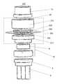
- FIG. 1Adepicts an exemplary faucet 100 that includes a prior art valve assembly 7 .
- the valve assemblyis a Delta® faucet valve cartridge model number RP50587.
- the exemplary faucet 100comprises an aerator 1 that fits into a spray head 3 , which may require use of a wrench 2 .
- the faucet 100also comprises a handle 4 , cap 5 , and bonnet nut 6 .
- the handle 4is attached to the valve assembly 7 , for example, using a set screw that can be tightened using an Allen wrench.
- FIG. 1Bshows three different views of the Delta RP50587 valve assembly 7 and corresponding puck 8 , which is integrated with waterways 9 comprising hot and cold water inlet lines and a water outlet line.
- the puckis attached to the bottom of the valve assembly 7 .
- FIGS. 1C-1Fdepict various views of the primary components of the exemplary valve assembly 7 .
- valve assembly 7comprises a movement control mechanism 10 and a valve mechanism 12 .
- the movement control mechanism 10comprises a stem assembly 24 , which can be attached to a handle 4 .
- the valve assemblycomprises a movable ceramic disc 14 and a stationary Diamond-embedded disc 16 .
- the stem assembly 24includes a ball 22 having a knuckle 18 that can be placed into a recess 20 of the ceramic disc 14 .
- the ball 22is movable within a housing 26 , where its movement is constrained by a handle limit stop 28 .
- a rubber gasket 30provides a seal with puck 8 .
- the purpose of the two discs 14 and 16is to control whether hot and/or cold water flow through the valve and the mixing of the hot and cold water.
- the two discsare also configured to provide a seal such that water stays below the ceramic disc 14 and does not leak out into the faucet 100 .
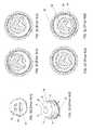
- FIGS. 1G-1Ldepict the exemplary moveable disc 14 and stationary disc 16 and depict how relative alignment of the two discs controls the water mixing of the valve.
- FIG. 1Cdepicts the Diamond-embedded disc 16 having water inlet holes 32 for receiving hot and cold water and a water outlet hole 34 .
- FIG. 1Hdepicts the top of the movable disc 14 , which has a recess 20 in which the knuckle 18 associated with the ball 22 resides.
- the ball 22 and handle limit stop 28limit the movement of the handle 4 and constrain the movement of the movable disc 14 such that it can only move translationally and not rotationally relative to the stationary disc 16 as indicated by the arrows.
- FIGS. 1I-1LFour different locations of the moveable disc 14 relative to the bottom of the housing 26 of the movement control mechanism are shown in FIGS. 1I-1L .
- the bottom of the moveable disc 14includes a channel 36 , a central portion 38 , and an outer portion 40 .
- movement of the knucklecontrols translational movement of the moveable disc 14 and thereby controls the alignment of the channel 36 and central portion 38 of the moveable disc 14 relative to the water inlet holes 32 of the stationary disc 16 .
- rotational and/or translational movement of the stem 24moves the knuckle 18 that is located within the recess 20 of the ceramic disc 14 , which results in translational movement of the ceramic disc 14 relative to the diamond-embedded disc 16 .
- the relative location of the central portion 38 of the bottom of the ceramic disc 14 to the hot and cold water inlets 32 of the diamond-embedded disc 16controls whether the flow of hot and/or code water is on or off and also determines the mixing of the hot and cold water.
- FIGS. 1M and 1Ndepict solid and cutaway views of a simplified CAD model of the exemplary valve assembly 7 .
- valve assembly 7comprises movement control mechanism 10 , valve mechanism 12 , puck 8 , and waterways 9 .
- disc-based valve assembliestypically involve discs having precisely polished surfaces that provide a longer lasting seal, where the disc polishing process can be quite expensive. But, such assemblies can eventually develop leaks between the discs after extended periods of operation, which can result in substantial property damage and thus there remains a liability concern of faucet leakage. Therefore, an improved disc-based valve-system is desirable whereby disc polishing requirements are relieved and leakage of water between the discs is no longer a concern.
- a valve assemblycomprises a sealed container connected to a hot water supply line and a cold water supply line.
- the sealed containerhas an outlet for supplying at least one of hot water or cold water to a faucet.
- a valve mechanismis located inside the sealed container comprising a stationary mixing part and a moveable mixing part.
- a magnetic coupling adapterhas a first magnetic structure located outside of a wall of the sealed container.
- a first magnetic structureis made of a first magnetizable material having a first plurality of first printed maxels having a first polarity pattern.
- a second magnetic structure located inside the wall of the sealed containeris made of a second magnetizable material having a second plurality of second printed maxels having a second polarity pattern that is complementary to the first polarity pattern.
- the first magnetic structure and second magnetic structureare magnetically coupled across the wall of the sealed container.
- a first adapter interface component located outside of the wall of the sealed containeris associated with the first magnetic structure.
- a second adapter interface component located inside the wall of the sealed containeris associated with the second magnetic structure and the moveable mixing part.
- a movement control mechanismincludes a moveable handle associated with the first adapter interface, which is configured to control a movement of the magnetic coupling adapter and thereby a movement of the moveable mixing part to control flow and mixing of the hot and cold water.
- the stationary mixing partcomprises a first side and a second side opposite said first side.
- the first side of the stationary mixing partcan comprise a first inlet configured to receive hot water from hot water supply line, a second inlet configured to receive cold water from cold water supply line, and an outlet for supplying at least one of hot water and cold water to the faucet, with the first and second inlets and said outlet extending from the first side of the stationary mixing part to the second side of said stationary mixing part.
- the moveable mixing partcan comprises a first side and a second side opposite the first side.
- the first side of the moveable mixing partcan comprise an outer portion, an inner portion, and a channel.
- the second side of the stationary mixing part and the first side of the movable mixing partcan be configured to interface with each other to provide a seal intended to prevent leakage of at least one of the cold water and hot water out of the valve mechanism.
- a location of the inner portion of the first side of the moveable mixing part relative to the first and second inlets of the second side of the stationary mixing partcontrols the flow and the mixing of hot water and cold water.
- a moveable handlecan be configured for rotational movement or translational movement.
- the movement control mechanismfurther comprises a stem assembly attached to the handle and associated with said the adapter interface component, in one embodiment, the stem assembly comprises a ball having a knuckle that can be placed into a recess of the first adapter interface component.
- the ballcan be movable within a housing or constrained.
- the movement of the moveable mixing partcan be rotational movement or a translational movement.
- a puckcan be associated with the stationary mixing part.
- a gasketcan be positioned between the puck and the stationary mixing part.
- a tap betweencan be positioned between least one of the cold water supply line and the hot water supply line and the sealed container.
- a pistoncan be connected to the tap.
- the sealed containercan be filled with grease.
- FIG. 1Adepicts an exemplary faucet that includes a prior art valve assembly.
- FIG. 1Bshows three different views of the valve assembly of FIG. 1 .
- FIGS. 1C-1Fdepict various views of the primary components of the valve assembly of FIG. 1 .
- FIGS. 1G-1Ldepict a moveable disc and a stationary disc in the valve assembly of FIG. 1 .
- FIGS. 1M and 1Ndepict solid and cutaway views of a simplified CAD model of the valve assembly of FIG. 1 .
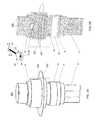
- FIGS. 2A and 2Bdepict solid and cutaway views of an exemplary valve assembly according to the present invention.
- FIGS. 2C and 2Ddepict solid and cutaway views of the components of a magnetic coupling adapter of the valve assembly shown in FIGS. 2A and 2B .
- FIGS. 3A and 3Bdepict exemplary first and second magnetic structures used in the valve assembly shown in FIGS. 2A and 2B .
- FIG. 3Cshows maxels printed from the top side of a magnetic material.
- FIG. 3Ddepicts maxels printed from both sides of a material that resemble cylinders.
- FIGS. 3E and 3Fdepicts overlapping maxels printed on a magnetic material.
- FIGS. 3G and 3Hdepict complementary alignment of magnetic structures.
- FIGS. 4A and 4Bdepict top and side views of exemplary shunt plates.
- FIG. 5Adepicts a first magnetic structure on a first side of a barrier and a second magnetic structure on the a second side of the barrier.
- FIG. 5Bdepicts a first magnetic structure on a first side of a barrier and a second magnetic structure on a second side of the barrier 202 that is opposite the first side of the barrier.
- FIG. 5Cdepicts a solid view of an exemplary valve assembly that is the same as the valve assembly of FIGS. 2A-2D except shunt plates are shown above the first magnetic structure and beneath the second magnetic structure.
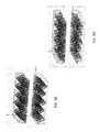
- FIGS. 6A and 6Bdepict views of the maxel pattern on the bottom side of a first magnetic structure and the maxel pattern on the top side of a second magnetic structure.
- FIG. 6Cdepicts the top side of the first magnetic structure when placed on top of the second magnetic structure, where a barrier is showing being between the two structures.
- FIG. 7depicts a valve assembly according to another embodiment of the present invention.
- Certain described embodiments of the invention described hereinmay relate by way of example, but not limitation, to systems and/or apparatuses comprising magnetic structures, magnetic and non-magnetic materials, methods for using magnetic structures, magnetic structures produced via magnetic printing, magnetic structures comprising arrays of discrete magnetic elements, combinations thereof, and so forth.
- Example realizations for such embodimentsmay be facilitated, at least in part, by the use of an emerging, revolutionary technology that may be termed correlated magnetics.
- This revolutionary technology referred to herein as correlated magneticswas first fully described and enabled in the co-assigned U.S. Pat. No. 7,800,471 issued on Sep. 21, 2010, and entitled “A Field Emission System and Method”. The contents of this document are hereby incorporated herein by reference.
- a second generation of a correlated magnetic technologyis described and enabled in the co-assigned U.S. Pat. No. 7,868,721 issued on Jan. 11, 2011, and entitled “A Field Emission System and Method”. The contents of this document are hereby incorporated herein by reference.
- a third generation of a correlated magnetic technologyis described and enabled in the co-assigned U.S. Pat. No. 8,179,219, issued May 15, 2012, and entitled “A Field Emission System and Method”. The contents of this document are hereby incorporated herein by reference.
- Another technology known as correlated inductance, which is related to correlated magneticshas been described and enabled in the co-assigned U.S. Pat. No. 8,115,581 issued on Feb. 14, 2012, and entitled “A System and Method for Producing an Electric Pulse”. The contents of this document are hereby incorporated by reference.
- Material presented hereinmay relate to and/or be implemented in conjunction with multilevel correlated magnetic systems and methods for producing a multilevel correlated magnetic system such as described in U.S. Pat. No. 7,982,568 issued Jul. 19, 2011 which is all incorporated herein by reference in its entirety.
- Material presented hereinmay relate to and/or be implemented in conjunction with systems and methods pertaining to magnetic coupling across a barrier such as described in U.S. Pat. No. 8,222,986 issued Jul. 17, 2012, which is all incorporated herein by reference in its entirety. Material presented herein may relate to and/or be implemented in conjunction with systems and methods pertaining to magnetic coupling across a barrier such as described in U.S. Pat. No. 8,704,626 issued Apr. 22, 2014, which is all incorporated herein by reference in its entirety.
- a magnetic valve assemblycomprises a movement control mechanism and a valve mechanism.
- the movement control mechanismcomprises a first magnetic structure having a first plurality of magnetic source regions having a first polarity pattern and a second magnetic structure having a second plurality of magnetic source regions having a second polarity pattern that is complementary to said first polarity pattern.
- the first magnetic structureis placed into complementary alignment with the second magnetic structure such that the two magnetic structures are magnetically coupled (attached) across a plane corresponding to a barrier, for example, a wall of a sealed container to which hot and cold water supply lines are connected to respective hot and cold water inlets and from which water can be supplied via a water outlet.
- the movement control mechanismincludes a moveable handle that can rotate and/or translate, where the handle is attached to a stem or lever that is attached or otherwise associated with the first magnetic structure such that movement of the handle controls rotational and/or translational movement of the first magnetic structure.
- the valve mechanismcomprises two or more discs including at least one movable disc and a stationary (or fixed) disc constituting each constituting a corresponding mixing parts, where the relative location of the at least one movable mixing part/disc relative to the stationary mixing part/disc determines the alignment of holes and/or channels associated with the mixing parts/discs that determines whether hot and/or cold water flows through the valve and also the mixing of the hot and cold water.
- the second magnetic structureis attached to or otherwise associated with the at least one movable disc such that rotational and/or translational movement of the first magnetic structure produces respective rotational and/or translational movement of the second magnetic structure and the at least one moveable disc.
- FIGS. 2A and 2Bdepict solid and cutaway views of an exemplary valve assembly 200 according to one embodiment of the invention.
- the valve assembly 200comprises the movement control mechanism 10 , valve mechanism 12 , puck 8 , and waterways 9 of the exemplary valve assembly 7 plus a magnetic coupling adapter 204 that enables magnetic coupling across a non-ferromagnetic material barrier 202 that is part of a sealed container, where the adapter can move translationally relative to the barrier 202 , where the barrier 202 remains fixed relative to the adapter 204 .
- the adapter 204includes a recess 20 for receiving the knuckle 18 of the ball 22 of the movement control mechanism 10 and includes a cavity for receiving the ceramic disc 14 .
- the translational movement of the magnetic coupling adapter 204 of the exemplary modified valve assembly 200is controlled by the movement control mechanism 10 in the same manner as the ceramic disc 14 was controlled in the exemplary valve assembly 7 and because the adapter 204 can move translationally relative to the barrier 202 the movement of the ceramic disc 14 , which is attached to or otherwise associated with the adapter 204 moves in the same manner as if it were instead attached to or otherwise associated with the movement control mechanism 10 .
- FIGS. 2C and 2Ddepict solid and cutaway views of the components of the magnetic coupling adapter 204 of the valve assembly 200 .
- magnetic coupling adapter 204comprises a first magnetic structure 206 and a second magnetic structure 208 that are on opposite sides of the barrier 202 , where the two magnetic structures are magnetically coupled (or attached) across the barrier 202 that formed a sealed container.
- a first adapter interface component 210includes a recess 20 on its topside for receiving the knuckle 18 of the movement control system 10 and has a cavity on its bottom side for receiving the first magnetic structure 206 .
- a second adapter interface component 212includes a cavity on its top side for receiving the second magnetic structure 206 and a cavity on its bottom side for receiving ceramic disc.
- the magnetic structuresneed not the round and that the magnetic structures and ceramic discs can be secured in their respective cavities in various ways.
- the magnetic structures and ceramic discscan be secured in their respective cavities using an adhesive or using set screws.
- FIGS. 2C and 2Dare optional shunt plates that would be located on top of the first magnetic structure and beneath the second magnetic structure.
- the shunt platescould be placed into the respective cavities for receiving the magnetic structures prior to the magnetic structures being placed into the cavities or, alternatively, the shunt plates could be attached, for example using an adhesive, to the magnetic structures prior to their being placed into their respective cavities. Shunt plates are described in U.S. patent application Ser. No. 13/374,074 filed Dec.
- anti-friction layersthat can be placed between each of the two magnetic structures and the barrier 202 .
- anti-friction layersare layers of an anti-friction tape such as a Teflon-coated tape, where the tape can be attached to the magnetic structures or may be attached to the barrier.
- the second magnetic structurecould be integrated directly into the ceramic disc 14 and that many different configurations of magnetic structures can be used to provide the magnetic coupling across the barrier of the sealed container.
- the first magnetic structurecould have a recess or hole that functions like recess 20 of the ceramic disc 14 .
- FIGS. 3A and 3Bdepict exemplary first and second magnetic structures 206 , 208 , respectively, which have magnetic sources having complementary polarity patterns.
- magnetic sourcesare represented by circles having either a + or ⁇ symbol, where a + represents a positive (or North) polarity magnetic source 302 and a ⁇ represents a negative (or South) polarity magnetic source 304 .
- the polarity patterns of two structuresare complementary such that when the bottom of the first magnetic structure is placed on top of the second magnetic structure in a complementary alignment position, the various magnetic sources of the two structures will each be aligned with a magnetic source that is of opposite polarity such that the two magnetic structure produce a peak spatial attract force.
- magnetic sourcesmay be discrete magnets integrated into or onto a substrate or, preferably, may be magnetic sources printed into magnetizable material, which may be referred to as maxels, and the polarities and relative locations of the magnetic sources can be selected to achieve desirable shear and/or torque characteristics.
- maxelsmay be arranged in concentric circles where the maxels of each circle are offset from maxels of adjacent circles or where the maxels of each circle are arranged to resemble a radial pattern, which might be used given a requirement for rotational movement by the movement control mechanism.
- Maxel polaritiesmay be selected to provide a substantially uniform shear behavior in all translational directions or selected to provide different shear behaviors depending on the direction of movement.
- maxel field strengthsmay be varied, maxel sizes may be varied, maxel shapes may be varied, etc.
- maxels or of groups of maxelscan be selected based on characteristics of the magnetic material being used, for example the grade and thickness of the material.
- Maxelsmay be printed from only one side of the material or from both sides of the material.
- the dotted lines of FIG. 3Crepresent maxels printed from the top side of the magnetic material.
- the portion of the maxels within the materialresemble parabaloids, which is a shape selected as a representation (or model) of the actual shapes of the maxels inside of the material.
- Another shape used to represent maxelsis a conic shape, which resembles a Dixie cup.
- 3Ddepicts maxels printed from both sides of the material that resemble cylinders, which is yet another shape selected as a representation (or model) of the actual shapes of the maxels inside of the material.
- maxelsprinted from both sides of the material that resemble cylinders, which is yet another shape selected as a representation (or model) of the actual shapes of the maxels inside of the material.
- the actual shape of maxels, whether printed from one side, two sides, or even more sides of a piece of materialdepends on numerous printing parameters and material parameters and that all sorts of magnetic structures including those having maxels printed inside of maxels can be used in accordance with the invention. Maxel printing techniques are described in U.S. patent application Ser. No. 13/240,335 filed Sep. 22, 2011, which is incorporated by reference in its entirety.
- a two-dimensional pattern of rows and columns of alternating polarity magnetic sourcescan be used.
- the magnetic sources of a given rowmay be shifted relative to an adjoining row of magnetic sources such as depicted in FIGS. 3A and 3B .
- Maxelsmay be printed such that they abut each other such as shown in FIG. 3C or they may be printed such that they overlap as depicted in FIGS. 3E and 3F .
- Different sized maxelscan be used within the same magnetic structure, sacrificial material may be used during printing, and so on.
- FIGS. 3G and 3Hdepict complementary alignment of magnetic structures using maxels represented by parabaloid and conic shapes, respectively.
- FIGS. 4A and 4Bdepict top and side views of exemplary shunt plates that can be used in accordance with the invention.
- FIG. 5Adepicts a first magnetic structure 206 on a first side of a barrier 202 and a second magnetic structure 208 on the a second side of the barrier 202 that is opposite the first side of the barrier 202 , thereby forming the sealed container, where shunt plates 402 are shown on top of the first magnetic structure 206 and beneath the second magnetic structure 208 .
- FIG. 5Bdepicts a first magnetic structure 206 on a first side of a barrier 202 and a second magnetic structure 208 on the a second side of the barrier 202 that is opposite the first side of the barrier 202 , where shunt plates 402 are shown on top of the first magnetic structure 206 and beneath the second magnetic structure 208 and anti-friction layers 502 (e.g., Teflon tape) are shown between the magnetic structures 206 , 208 and the barrier 202 .
- anti-friction layers 502e.g., Teflon tape
- FIG. 5Cdepicts a solid view of an exemplary valve assembly 500 that is the same as the valve assembly 200 of FIGS. 2A-2D except shunt plates 402 are shown above the first magnetic structure 206 and beneath the second magnetic structure 208 .
- the magnetic structures used in the inventionare magnetized to exhibit multi-level magnetism behavior.
- structures exhibiting contactless attachment behaviorcan be constrained to minimize contact with the barrier yet provide magnetic attachment and sufficient shear/torque necessary to remain coupled when controlling the valve mechanism 12 .
- FIGS. 6A and 6Bdepict views of the maxel pattern on the bottom side of a first magnetic structure 602 and the maxel pattern on the top side of a second magnetic structure 604 , where the maxels have been printed on a conventionally magnetized material.
- the printing of negative polarity maxels on the negative side of a conventional magnet or printing of positive polarity maxels on the positive side of a conventional magnetis optional.
- FIG. 6Cdepicts the top side of the first magnetic structure 602 when placed on top of the second magnetic structure 604 , where a barrier 202 is shown being between the two structures. As shown, the two magnetic structures are constrained on that movement is restricted to the directions indicated by the arrows.
- FIG. 7depicts a valve assembly 700 , which is like the valve assembly 200 except the puck encompasses all the components shown within the dotted region such that a hermetically sealed container is created.
- a tap 702 of the cold (or hot) water supply line into the containercan be used to fill the container with water so as to equalize the pressure in the container. When water pressure has been equalized, water will not leak between the two disks.
- the containercan be filled with grease or some other material and a membrane or piston can be connected to the tap 702 to equalize pressure in the container.
Landscapes
- Engineering & Computer Science (AREA)
- General Engineering & Computer Science (AREA)
- Mechanical Engineering (AREA)
- Physics & Mathematics (AREA)
- Electromagnetism (AREA)
- Power Engineering (AREA)
- Multiple-Way Valves (AREA)
Abstract
Description
This application claims the benefit under 35 USC 119(e) of provisional application 61/871,689, titled “Magnetic Valve Assembly”, filed Aug. 29, 2013 by Fullerton et al.
This application is a continuation-in-part of non-provisional application Ser. No. 14/198,226, titled “Correlated Magnetic System and Method”, filed Mar. 5, 2014 by Fullerton et al., which claims the benefit under 35 USC 119(e) of provisional applications 61/794,427, titled “Method for Correcting Bias in Correlated Field Emission Structures”, filed Mar. 15, 2013 by Fullerton et al., 61/798,233, titled “Method for Using Symbols in Coded Field Emission Structures”, filed Mar. 15, 2013 by Roberts et al., 61/798,453, titled “Apparatus and Method for Mechanical Augmentation of Correlated Field Emission Structures”, filed Mar. 15, 2013 by Fullerton, 61/799,507, titled “Apparatus and Method for Constraining Field Emission Structures”, filed Mar. 15, 2013 by Fullerton et al, and 61/800,377, titled “Method for Making and Using Composite Coded Field Emission Structures”, filed Mar. 15, 2013 by Roberts et al.
Non-provisional application Ser. No. 14/198,226 is a continuation-in-part of non-provisional application Ser. No. 14/103,760, titled “An Intelligent Magnetic System”, filed Dec. 11, 2013 by Fullerton et al., which claims the benefit under 35 USC 119(e) of provisional application 61/735,460, titled “An Intelligent Magnetic System”, filed Dec. 10, 2012 by Fullerton et al.
Non-provisional application Ser. No. 14/103,760 is a continuation-in-part of non-provisional application Ser. No. 13/779,611, titled “System for Detaching a Magnetic Structure from a Ferromagnetic Material”, filed Feb. 27, 2013 by Fullerton et al., which claims the benefit under 35 USC 119(e) of provisional application 61/640,979, titled “System for Detaching a Magnetic Structure from a Ferromagnetic Material”, filed May 1, 2012 by Fullerton et al. and provisional application 61/604,376, titled “System for Detaching a Magnetic Structure from a Ferromagnetic Material”, filed Feb. 28, 2012 by Fullerton et al.
Non-provisional application Ser. No. 14/103,760 is also a continuation-in-part of non-provisional application Ser. No. 14/066,426, titled “System and Method for Affecting Flux of Magnetic Structures”, filed Oct. 29, 2013 by Fullerton et al., which is a continuation of U.S. Pat. No. 8,576,036, issued Nov. 5, 2013, which claims the benefit under 35 USC 119(e) of provisional application 61/459,994, titled “System and Method for Affecting Flux of Magnetic Structures”, filed Dec. 22, 2010 by Fullerton et al.
Non-provisional application Ser. No. 14/103,760 is also a continuation-in-part of non-provisional application Ser. No. 14/086,924, titled “System and Method for Positioning a Multi-Pole Magnetic Structure” filed Nov. 21, 2013 by Fullerton et al. which claims the benefit under 35 USC 119(e) of provisional application 61/796,863, titled “System for Determining a Position of a Multi-pole Magnetic Structure”, filed Nov. 21, 2012 by Fullerton et al.
Non-provisional application Ser. No. 14/086,924 is a continuation-in-part of non-provisional application Ser. No. 14/035,818, titled “Magnetic Structures and Methods for Defining Magnetic Structures Using One-Dimensional Codes” filed Sep. 24, 2013 by Fullerton et al, which claims the benefit under 35 USC 119(e) of provisional application 61/744,342, titled “Magnetic Structures and Methods for Defining Magnetic Structures Using One-Dimensional Codes”, filed Sep. 24, 2012 by Roberts.
Non-provisional application Ser. No. 14/035,818 is a continuation-in-part of non-provisional application Ser. No. 13/959,649, titled “Magnetic Device Using Non Polarized Magnetic Attraction Elements” filed Aug. 5, 2013 by Richards et al., now U.S. Pat. No. 8,692,637, which is a continuation-in-part of non-provisional application Ser. No. 13/759,695, titled “System and Method for Defining Magnetic Structures” filed Feb. 5, 2013 by Fullerton et al, now U.S. Pat. No. 8,502,630, which is a continuation of application Ser. No. 13/481,554, titled “System and Method for Defining Magnetic Structures”, filed May 25, 2012, by Fullerton et al., now U.S. Pat. No. 8,368,495, which is a continuation-in-part of non-provisional application Ser. No. 13/351,203, titled “A Key System For Enabling Operation Of A Device”, filed Jan. 16, 2012, by Fullerton et al., now U.S. Pat. No. 8,314,671 and claims the benefit under 35 USC 119(e) of provisional application 61/519,664, titled “System and Method for Defining Magnetic Structures”, filed May 25, 2011 by Roberts et al.
Non-provisional application Ser. No. 13/351,203 is a continuation of application Ser. No. 13/157,975, titled “Magnetic Attachment System with Low Cross Correlation”, filed Jun. 10, 2011, by Fullerton et al., now U.S. Pat. No. 8,098,122, which is a continuation of application Ser. No. 12/952,391, titled “Magnetic Attachment System”, filed Nov. 23, 2010 by Fullerton et al., now U.S. Pat. No. 7,961,069.
Non-provisional application Ser. No. 12/952,391 is a continuation of application Ser. No. 12/478,911, titled “Magnetically Attachable and Detachable Panel System” filed Jun. 5, 2009 by Fullerton et al., now U.S. Pat. No. 7,843,295.
Non-provisional application Ser. No. 12/952,391 is also a continuation of application Ser. No. 12/478,950, titled “Magnetically Attachable and Detachable Panel Method,” filed Jun. 5, 2009 by Fullerton et al., now U.S. Pat. No. 7,843,296.
Non-provisional application Ser. No. 12/952,391 is also a continuation of application Ser. No. 12/478,969, titled “Coded Magnet Structures for Selective Association of Articles,” filed Jun. 5, 2009 by Fullerton et al., now U.S. Pat. No. 7,843,297.
Non-provisional application Ser. No. 12/952,391 is also a continuation of application Ser. No. 12/479,013, titled “Magnetic Force Profile System Using Coded Magnet Structures,” filed Jun. 5, 2009 by Fullerton et al., now U.S. Pat. No. 7,839,247.
The preceding four applications are each a continuation-in-part of non-provisional application Ser. No. 12/476,952, filed Jun. 2, 2009, titled “A Field Emission System and Method”, by Fullerton et al., now U.S. Pat. No. 8,179,219, which is a continuation-in-part of non-provisional application Ser. No. 12/322,561, filed Feb. 4, 2009 titled “System and Method for Producing an Electric Pulse”, by Fullerton et al., now U.S. Pat. No. 8,115,581, which is a continuation-in-part of non-provisional application Ser. No. 12/358,423, filed Jan. 23, 2009 titled “A Field Emission System and Method”, by Fullerton et al., now U.S. Pat. No. 7,868,721, which is a continuation-in-part of non-provisional application Ser. No. 12/123,718, filed May 20, 2008 titled “A Field Emission System and Method”, by Fullerton et now U.S. Pat. No. 7,800,471, which claims the benefit of U.S. Provisional Patent Application No. 61/123,019, filed Apr. 4, 2008, which is entitled “A Field Emission System and Method”.
Non-provisional application Ser. No. 14/103,760 is also a continuation-in-part of U.S. patent application Ser. No. 13/918,921, filed Jun. 15, 2013 titled “Detachable Cover System”, by Fullerton et al., which is a continuation of U.S. patent application Ser. No. 13/629,879, filed Sep. 28, 2012, now U.S. Pat. No. 8,514,046, which is a continuation of U.S. patent application Ser. No. 13/426,909, filed Mar. 22, 2012, now U.S. Pat. No. 8,279,032, which is a continuation-in-part of U.S. non-provisional patent application Ser. No. 13/179,759, filed Jul. 11, 2011, now U.S. Pat. No. 8,174,347, and claims the benefit of U.S. Provisional Application 61/465,810, filed Mar. 24, 2011, which is entitled “Electromagnet Based Detachment System”.
Non-provisional application Ser. No. 14/103,760 is also a continuation-in-part of U.S. non-provisional patent application Ser. No. 14/045,756, filed Oct. 3, 2013, which is entitled “System and Method for Tailoring Transition Regions of Magnetic Structures”, now U.S. Pat. No. 8,810,348, which claims the benefit of U.S. Provisional Patent Application No. 61/744,864, filed Oct. 4, 2012, which is entitled “System And Method for Tailoring Polarity Transitions of Magnetic Structures”.
Non-provisional application Ser. No. 14/045,756 is a continuation-in-part of U.S. non-provisional patent application Ser. No. 13/240,335, filed Sep. 22, 2011, which is entitled “Magnetic Structure Production”, now U.S. Pat. No. 8,648,681, issued Feb. 11, 2014, which claims the benefit of U.S. Provisional Patent Application No. 61/403,814, filed Sep. 22, 2010 and U.S. Provisional Patent Application No. 61/462,715, filed Feb. 7, 2011, both of which are entitled “System And Method For Producing Magnetic Structures”.
Non-provisional application Ser. No. 13/240,335 is a continuation-in-part of U.S. Pat. No. 8,179,219, issued May 15, 2012, which is entitled “Field Emission System and Method”.
Non-provisional application Ser. No. 13/240,335 is also a continuation-in-part of U.S. non-provisional patent application Ser. No. 12/895,589, filed Sep. 30, 2010, now U.S. Pat. No. 8,760,250, which is entitled “A System And Method For Energy Generation”, which claims the benefit of Provisional Patent Application Nos. 61/277,214, filed Sep. 22, 2009, 61/277,900, filed Sep. 30, 2009, 61/278,767, filed Oct. 9, 2009, 61/279,094, filed Oct. 16, 2009, 61/281,160, filed Nov. 13, 2009, 61/283,780, filed Dec. 9, 2009, 61/284,385, filed Dec. 17, 2009, and 61/342,988, filed Apr. 22, 2010.
Non-provisional application Ser. No. 12/895,589 is a continuation-in-part of U.S. Pat. No. 7,982,568, issued Jul. 19, 2011, and U.S. Pat. No. 8,179,219, issued May 15, 2012; Ser. No. 14/045,756 is also a continuation-in-part of U.S. patent application Ser. No. 13/246,584, filed Sep. 27, 2011, which is entitled “System and Method for Producing Stacked Field Emission Structures”.
This application is also a continuation-in-part of non-provisional application Ser. No. 14/258,776, titled “System and Method for Moving an Object”, filed Apr. 22, 2014 by Fullerton et al., which is a continuation of non-provisional application Ser. No. 13/104,393, titled “System and Method for Moving and Object”, filed May 10, 2011, now U.S. Pat. No. 8,704,626, which claims the benefit under 35 USC 119(e) of provisional applications 61/395,205, titled “System and Method for Moving and Object”, filed May 5, 2010 by Fullerton et al.
The contents of the provisional patent applications, the contents of the non-provisional patent applications, and the contents of the issued patents that are identified above are hereby incorporated by reference in their entirety herein.
The present invention relates generally to a magnetic valve assembly. More particularly, the present invention relates to a valve assembly where the movement of a first disc relative to a second disc is controlled across a barrier using complementary magnetic structures.
Certain water valve assemblies that control the flow of hot and cold water into and out of faucets use a movement control mechanism to control a valve mechanism comprising two or more discs that are configured to control flow and mixing of hot and cold water while also providing a seal intended to prevent leakage of water out of the faucet. The movement control mechanism of such valve assemblies typically involves a moveable handle connected to a stem or lever that is rotated to rotate a first disc relative to a second disc. Alternatively, the stem may pivot a ball within a housing, where the ball has a knuckle that extends into a recess of a first disc configured to slide on a second disc that is fixed doesn't move). Generally, movement of the handle controls rotational and/or translational movement of the first disc relative to the second disc, where the relative location of the first disc to the second disc determines whether holes and/or channels associated with the discs are aligned which subsequently determines whether or not hot and/or cold water flows through the valve and also the mixing of hot and cold water flowing through the valve. With some assemblies, a third disc located between the first and second discs is used to provide a water film that lubricates the first and second discs and provides a seal. With other such assemblies, a lubricating grease is used to provide a seal. Examples of disc-based valve systems are described in U.S. Pat. No. 4,823,841 issued Apr. 25, 1989, U.S. Pat. No. 5,100,565 issued Mar. 31, 1992, U.S. Pat. No. 6,904,935 issued Jun. 14, 2005, U.S. Pat. No. 7,134,452 issued Nov. 14, 2006, U.S. Pat. No. 7,628,173 issued Dec. 8, 2009, and U.S. Pat. No. 7,980,268 issued Jul. 19, 2011, which are all incorporated herein in their entirety.
As explained above, modern disc-based valve assemblies typically involve discs having precisely polished surfaces that provide a longer lasting seal, where the disc polishing process can be quite expensive. But, such assemblies can eventually develop leaks between the discs after extended periods of operation, which can result in substantial property damage and thus there remains a liability concern of faucet leakage. Therefore, an improved disc-based valve-system is desirable whereby disc polishing requirements are relieved and leakage of water between the discs is no longer a concern.
Briefly, according to the present invention, a valve assembly comprises a sealed container connected to a hot water supply line and a cold water supply line. The sealed container has an outlet for supplying at least one of hot water or cold water to a faucet. A valve mechanism is located inside the sealed container comprising a stationary mixing part and a moveable mixing part. A magnetic coupling adapter has a first magnetic structure located outside of a wall of the sealed container. A first magnetic structure is made of a first magnetizable material having a first plurality of first printed maxels having a first polarity pattern. A second magnetic structure located inside the wall of the sealed container is made of a second magnetizable material having a second plurality of second printed maxels having a second polarity pattern that is complementary to the first polarity pattern. The first magnetic structure and second magnetic structure are magnetically coupled across the wall of the sealed container. A first adapter interface component located outside of the wall of the sealed container is associated with the first magnetic structure. A second adapter interface component located inside the wall of the sealed container is associated with the second magnetic structure and the moveable mixing part. A movement control mechanism includes a moveable handle associated with the first adapter interface, which is configured to control a movement of the magnetic coupling adapter and thereby a movement of the moveable mixing part to control flow and mixing of the hot and cold water.
According to some of the more detailed features of the invention, the stationary mixing part comprises a first side and a second side opposite said first side. The first side of the stationary mixing part can comprise a first inlet configured to receive hot water from hot water supply line, a second inlet configured to receive cold water from cold water supply line, and an outlet for supplying at least one of hot water and cold water to the faucet, with the first and second inlets and said outlet extending from the first side of the stationary mixing part to the second side of said stationary mixing part. The moveable mixing part can comprises a first side and a second side opposite the first side. The first side of the moveable mixing part can comprise an outer portion, an inner portion, and a channel. The second side of the stationary mixing part and the first side of the movable mixing part can be configured to interface with each other to provide a seal intended to prevent leakage of at least one of the cold water and hot water out of the valve mechanism.
According to other more featured of the invention, a location of the inner portion of the first side of the moveable mixing part relative to the first and second inlets of the second side of the stationary mixing part controls the flow and the mixing of hot water and cold water. A moveable handle can be configured for rotational movement or translational movement.
According to still other more featured of the invention, the movement control mechanism further comprises a stem assembly attached to the handle and associated with said the adapter interface component, in one embodiment, the stem assembly comprises a ball having a knuckle that can be placed into a recess of the first adapter interface component. The ball can be movable within a housing or constrained. The movement of the moveable mixing part can be rotational movement or a translational movement. A puck can be associated with the stationary mixing part. A gasket can be positioned between the puck and the stationary mixing part. A tap between can be positioned between least one of the cold water supply line and the hot water supply line and the sealed container. A piston can be connected to the tap. The sealed container can be filled with grease.
Certain described embodiments of the invention described herein may relate by way of example, but not limitation, to systems and/or apparatuses comprising magnetic structures, magnetic and non-magnetic materials, methods for using magnetic structures, magnetic structures produced via magnetic printing, magnetic structures comprising arrays of discrete magnetic elements, combinations thereof, and so forth. Example realizations for such embodiments may be facilitated, at least in part, by the use of an emerging, revolutionary technology that may be termed correlated magnetics. This revolutionary technology referred to herein as correlated magnetics was first fully described and enabled in the co-assigned U.S. Pat. No. 7,800,471 issued on Sep. 21, 2010, and entitled “A Field Emission System and Method”. The contents of this document are hereby incorporated herein by reference. A second generation of a correlated magnetic technology is described and enabled in the co-assigned U.S. Pat. No. 7,868,721 issued on Jan. 11, 2011, and entitled “A Field Emission System and Method”. The contents of this document are hereby incorporated herein by reference. A third generation of a correlated magnetic technology is described and enabled in the co-assigned U.S. Pat. No. 8,179,219, issued May 15, 2012, and entitled “A Field Emission System and Method”. The contents of this document are hereby incorporated herein by reference. Another technology known as correlated inductance, which is related to correlated magnetics, has been described and enabled in the co-assigned U.S. Pat. No. 8,115,581 issued on Feb. 14, 2012, and entitled “A System and Method for Producing an Electric Pulse”. The contents of this document are hereby incorporated by reference.
Material presented herein may relate to and/or be implemented in conjunction with multilevel correlated magnetic systems and methods for producing a multilevel correlated magnetic system such as described in U.S. Pat. No. 7,982,568 issued Jul. 19, 2011 which is all incorporated herein by reference in its entirety.
Material presented herein may relate to and/or be implemented in conjunction with systems and methods pertaining to magnetic coupling across a barrier such as described in U.S. Pat. No. 8,222,986 issued Jul. 17, 2012, which is all incorporated herein by reference in its entirety. Material presented herein may relate to and/or be implemented in conjunction with systems and methods pertaining to magnetic coupling across a barrier such as described in U.S. Pat. No. 8,704,626 issued Apr. 22, 2014, which is all incorporated herein by reference in its entirety.
Such systems and methods described in U.S. Pat. No. 7,681,256 issued Mar. 23, 2010, U.S. Pat. No. 7,750,781 issued Jul. 6, 2010, U.S. Pat. No. 7,755,462 issued Jul. 13, 2010, U.S. Pat. No. 7,812,698 issued Oct. 12, 2010, U.S. Pat. Nos. 7,817,002, 7,817,003, 7,817,004, 7,817,005, and 7,817,006 issued Oct. 19, 2010, U.S. Pat. No. 7,821,367 issued Oct. 26, 2010, U.S. Pat. Nos. 7,823,300 and 7,824,083 issued Nov. 2, 2011, U.S. Pat. No. 7,834,729 issued Nov. 16, 2011, U.S. Pat. No. 7,839,247 issued Nov. 23, 2010, U.S. Pat. Nos. 7,843,295, 7,843,296, and 7,843,297 issued Nov. 30, 2010, U.S. Pat. No. 7,893,803 issued Feb. 22, 2011, U.S. Pat. Nos. 7,956,711 and 7,956,712 issued Jun. 7, 2011, U.S. Pat. Nos. 7,958,575, 7,961,068 and 7,961,069 issued Jun. 14, 2011, U.S. Pat. No. 7,963,818 issued Jun. 21, 2011, and U.S. Pat. Nos. 8,015,752 and 8,016,330 issued Sep. 13, 2011, and U.S. Pat. No. 8,035,260 issued Oct. 11, 2011, and U.S. Pat. No. 8,174,347 issued May 8, 2012, and U.S. Pat. Nos. 8,279,031 and 8,279,032 issued Oct. 2, 2012, and U.S. Pat. No. 8,368,495 issued Feb. 5, 2013 are all incorporated by reference herein in their entirety.
Such systems and methods described in U.S. Pat. No. 8,648,681 issued Feb. 11, 2014, U.S. Pat. No. 8,760,251 issued Jun. 24, 2014, and U.S. Pat. No. 8,576,036 issued Nov. 5, 2013, and U.S. patent application Ser. No. 13/604,939 filed Sep. 6, 2012, Ser. No. 13/659,444 filed Oct. 23, 2012, Ser. No. 13/687,819 filed Nov. 28, 2012, Ser. No. 13/779,611 filed Feb. 27, 2013, and Ser. No. 13/959,201 filed Aug. 5, 2013, which are all incorporated by reference herein in their entirety.
In accordance with one aspect of the invention, a magnetic valve assembly comprises a movement control mechanism and a valve mechanism. The movement control mechanism comprises a first magnetic structure having a first plurality of magnetic source regions having a first polarity pattern and a second magnetic structure having a second plurality of magnetic source regions having a second polarity pattern that is complementary to said first polarity pattern. The first magnetic structure is placed into complementary alignment with the second magnetic structure such that the two magnetic structures are magnetically coupled (attached) across a plane corresponding to a barrier, for example, a wall of a sealed container to which hot and cold water supply lines are connected to respective hot and cold water inlets and from which water can be supplied via a water outlet. The movement control mechanism includes a moveable handle that can rotate and/or translate, where the handle is attached to a stem or lever that is attached or otherwise associated with the first magnetic structure such that movement of the handle controls rotational and/or translational movement of the first magnetic structure.
The valve mechanism comprises two or more discs including at least one movable disc and a stationary (or fixed) disc constituting each constituting a corresponding mixing parts, where the relative location of the at least one movable mixing part/disc relative to the stationary mixing part/disc determines the alignment of holes and/or channels associated with the mixing parts/discs that determines whether hot and/or cold water flows through the valve and also the mixing of the hot and cold water. The second magnetic structure is attached to or otherwise associated with the at least one movable disc such that rotational and/or translational movement of the first magnetic structure produces respective rotational and/or translational movement of the second magnetic structure and the at least one moveable disc.
The present invention will now be described more fully in detail with reference to the accompanying drawings, in which the preferred embodiments of the invention are shown. This invention should not, however, be construed as limited to the embodiments set forth herein; rather, they are provided so that this disclosure will be thorough and complete and will fully convey the scope of the invention to those skilled in the art.
One skilled in the art will understand that the magnetic structures need not the round and that the magnetic structures and ceramic discs can be secured in their respective cavities in various ways. For example, the magnetic structures and ceramic discs can be secured in their respective cavities using an adhesive or using set screws. Not shown inFIGS. 2C and 2D are optional shunt plates that would be located on top of the first magnetic structure and beneath the second magnetic structure. The shunt plates could be placed into the respective cavities for receiving the magnetic structures prior to the magnetic structures being placed into the cavities or, alternatively, the shunt plates could be attached, for example using an adhesive, to the magnetic structures prior to their being placed into their respective cavities. Shunt plates are described in U.S. patent application Ser. No. 13/374,074 filed Dec. 9, 2011, which is incorporated herein by reference in its entirety. Also not shown are optional anti-friction layers that can be placed between each of the two magnetic structures and thebarrier 202. Examples of anti-friction layers are layers of an anti-friction tape such as a Teflon-coated tape, where the tape can be attached to the magnetic structures or may be attached to the barrier.
One skilled in the art will recognize that instead of using the secondadapter interface component 212, the second magnetic structure could be integrated directly into theceramic disc 14 and that many different configurations of magnetic structures can be used to provide the magnetic coupling across the barrier of the sealed container. For example, the first magnetic structure could have a recess or hole that functions likerecess 20 of theceramic disc 14.
One skilled in the art will understand that magnetic sources may be discrete magnets integrated into or onto a substrate or, preferably, may be magnetic sources printed into magnetizable material, which may be referred to as maxels, and the polarities and relative locations of the magnetic sources can be selected to achieve desirable shear and/or torque characteristics. For example, maxels may be arranged in concentric circles where the maxels of each circle are offset from maxels of adjacent circles or where the maxels of each circle are arranged to resemble a radial pattern, which might be used given a requirement for rotational movement by the movement control mechanism. Maxel polarities may be selected to provide a substantially uniform shear behavior in all translational directions or selected to provide different shear behaviors depending on the direction of movement. Similarly, to achieve desired shear or torque characteristics, maxel field strengths may be varied, maxel sizes may be varied, maxel shapes may be varied, etc.
One skilled in the art will understand that the size and shape of maxels or of groups of maxels can be selected based on characteristics of the magnetic material being used, for example the grade and thickness of the material. Maxels may be printed from only one side of the material or from both sides of the material. The dotted lines ofFIG. 3C represent maxels printed from the top side of the magnetic material. As shown, the portion of the maxels within the material resemble parabaloids, which is a shape selected as a representation (or model) of the actual shapes of the maxels inside of the material. Another shape used to represent maxels is a conic shape, which resembles a Dixie cup.FIG. 3D depicts maxels printed from both sides of the material that resemble cylinders, which is yet another shape selected as a representation (or model) of the actual shapes of the maxels inside of the material. One skilled in the art will understand that the actual shape of maxels, whether printed from one side, two sides, or even more sides of a piece of material depends on numerous printing parameters and material parameters and that all sorts of magnetic structures including those having maxels printed inside of maxels can be used in accordance with the invention. Maxel printing techniques are described in U.S. patent application Ser. No. 13/240,335 filed Sep. 22, 2011, which is incorporated by reference in its entirety.
Under one arrangement a two-dimensional pattern of rows and columns of alternating polarity magnetic sources can be used. Under another arrangement, the magnetic sources of a given row may be shifted relative to an adjoining row of magnetic sources such as depicted inFIGS. 3A and 3B . Maxels may be printed such that they abut each other such as shown inFIG. 3C or they may be printed such that they overlap as depicted inFIGS. 3E and 3F . Different sized maxels can be used within the same magnetic structure, sacrificial material may be used during printing, and so on.
Under one arrangement, the magnetic structures used in the invention are magnetized to exhibit multi-level magnetism behavior. For example, structures exhibiting contactless attachment behavior can be constrained to minimize contact with the barrier yet provide magnetic attachment and sufficient shear/torque necessary to remain coupled when controlling thevalve mechanism 12.FIGS. 6A and 6B depict views of the maxel pattern on the bottom side of a firstmagnetic structure 602 and the maxel pattern on the top side of a secondmagnetic structure 604, where the maxels have been printed on a conventionally magnetized material. As such, the printing of negative polarity maxels on the negative side of a conventional magnet or printing of positive polarity maxels on the positive side of a conventional magnet is optional.FIG. 6C depicts the top side of the firstmagnetic structure 602 when placed on top of the secondmagnetic structure 604, where abarrier 202 is shown being between the two structures. As shown, the two magnetic structures are constrained on that movement is restricted to the directions indicated by the arrows.
While particular embodiments of the invention have been described, it will be understood, however, that the invention is not limited thereto, since modifications may be made by those skilled in the art, particularly in light of the foregoing teachings.
Claims (20)
1. A valve assembly, comprising:
a sealed container connected to a hot water supply line and a cold water supply line, said sealed container having an outlet for supplying at least one of a hot water or a cold water to a faucet;
a valve mechanism located side said sealed container, said valve mechanism comprising:
a stationary mixing part; and
a moveable mixing part;
a magnetic coupling adapter, comprising:
a first magnetic structure located outside of a wall of said seated container, said first magnetic structure being a first magnetizable material having a first plurality of first printed maxels having a first polarity pattern;
a second magnetic structure located inside said wall of said sealed container, said second magnetic structure being a second magnetizable material having a second plurality of second printed maxels having a second polarity pattern that is complementary to said first polarity pattern, said first magnetic structure and said second magnetic structure being magnetically coupled across said wall of said sealed container;
a first adapter interface component located outside of a wall of said sealed container and associated with said first magnetic structure; and
a second adapter interface component located inside said wall of said seated container and associated with said second magnetic structure and said moveable mixing part; and
a movement control mechanism including a moveable handle associated with said first adapter interface and configured to control a movement of said magnetic coupling adapter and thereby a movement of said moveable mixing part to control flow and mixing of said hot and said cold water.
2. The valve assembly ofclaim 1 , wherein said stationary mixing part comprises a first side and a second side apposite said first side.
3. The valve assembly ofclaim 2 , wherein said first side of said stationary mixing part comprises first inlet configured to receive said hot water from said hot water supply line, a second inlet configured to receive said cold water from said cold water supply line, and an outlet for supplying at least one of said hot water and said cold water to said faucet, said first and second inlets and said outlet extending from said first side of said stationary mixing part to said second side of said stationary mixing part.
4. The valve assembly ofclaim 3 , wherein said moveable mixing part comprises a first side and a second side opposite said first side.
5. The valve assembly ofclaim 4 , wherein said first side of said moveable mixing part comprises an outer portion, an inner portion, and a channel.
6. The valve assembly ofclaim 5 , wherein said second side of said stationary mixing part and said first side of said movable mixing part are configured to interface with each other to provide a seal intended to prevent leakage of at least one of said cold water and said hot water out of said valve mechanism.
7. The valve assembly ofclaim 5 , wherein a location of said inner portion of said first side of said moveable mixing part relative to the first and second inlets of said second side of said stationary mixing part controls said flow and said mixing of said hot water and said cold water.
8. The valve assembly ofclaim 1 , wherein said moveable handle is configured for rotational movement.
9. The valve assembly ofclaim 1 , wherein said moveable handle is configured for translational movement.
10. The valve assembly ofclaim 1 , wherein said movement control mechanism further comprises:
a stem assembly attached to said handle and associated with said first adapter interface component.
11. The valve assembly ofclaim 10 , where said stem assembly comprises a ball having a knuckle that can be placed into a recess of said first adapter interface component.
12. The valve assembly ofclaim 11 , wherein said ball movable within a housing.
13. The valve assembly ofclaim 11 , wherein movement of said ball is constrained.
14. The valve assembly ofclaim 1 , wherein said movement of said moveable mixing part is a rotational movement.
15. The valve assembly ofclaim 1 , wherein said movement of said moveable mixing part is a translational movement.
16. The valve assembly ofclaim 1 , further comprising:
a puck associated with said stationary mixing part.
17. The valve assembly ofclaim 16 , further comprising:
a gasket between said puck and said stationary mixing part.
18. The valve assembly ofclaim 1 , further comprising:
a tap between at least one of the cold water supply line and the hot water supply line and the sealed container.
19. The valve assembly ofclaim 18 , further comprising a piston connected to said tap.
20. The valve assembly ofclaim 1 , where the sealed container is filled with grease.
Priority Applications (4)
| Application Number | Priority Date | Filing Date | Title |
|---|---|---|---|
| US14/472,945US9371923B2 (en) | 2008-04-04 | 2014-08-29 | Magnetic valve assembly |
| US15/188,760US20160298787A1 (en) | 2009-01-23 | 2016-06-21 | Magnetic valve assembly |
| US15/352,135US10173292B2 (en) | 2009-01-23 | 2016-11-15 | Method for assembling a magnetic attachment mechanism |
| US15/611,544US20170268691A1 (en) | 2009-01-23 | 2017-06-01 | Magnetic Attachment System Having a Multi-Pole Magnetic Structure and Pole Pieces |
Applications Claiming Priority (58)
| Application Number | Priority Date | Filing Date | Title |
|---|---|---|---|
| US12301908P | 2008-04-04 | 2008-04-04 | |
| US12/123,718US7800471B2 (en) | 2008-04-04 | 2008-05-20 | Field emission system and method |
| US12/358,423US7868721B2 (en) | 2008-04-04 | 2009-01-23 | Field emission system and method |
| US12/322,561US8115581B2 (en) | 2008-04-04 | 2009-02-04 | Techniques for producing an electrical pulse |
| US12/476,952US8179219B2 (en) | 2008-04-04 | 2009-06-02 | Field emission system and method |
| US12/479,013US7839247B2 (en) | 2008-04-04 | 2009-06-05 | Magnetic force profile system using coded magnet structures |
| US12/478,911US7843295B2 (en) | 2008-04-04 | 2009-06-05 | Magnetically attachable and detachable panel system |
| US12/478,950US7843296B2 (en) | 2008-04-04 | 2009-06-05 | Magnetically attachable and detachable panel method |
| US12/478,969US7843297B2 (en) | 2008-04-04 | 2009-06-05 | Coded magnet structures for selective association of articles |
| US27721409P | 2009-09-22 | 2009-09-22 | |
| US27790009P | 2009-09-30 | 2009-09-30 | |
| US27876709P | 2009-10-09 | 2009-10-09 | |
| US27909409P | 2009-10-16 | 2009-10-16 | |
| US28116009P | 2009-11-13 | 2009-11-13 | |
| US28378009P | 2009-12-09 | 2009-12-09 | |
| US28438509P | 2009-12-17 | 2009-12-17 | |
| US34298810P | 2010-04-22 | 2010-04-22 | |
| US12/885,450US7982568B2 (en) | 2009-09-22 | 2010-09-18 | Multilevel correlated magnetic system and method for using same |
| US40381410P | 2010-09-22 | 2010-09-22 | |
| US40414710P | 2010-09-27 | 2010-09-27 | |
| US12/895,589US8760250B2 (en) | 2009-06-02 | 2010-09-30 | System and method for energy generation |
| US12/952,391US7961069B2 (en) | 2008-04-04 | 2010-11-23 | Magnetic attachment system |
| US201061459994P | 2010-12-22 | 2010-12-22 | |
| US201161462715P | 2011-02-07 | 2011-02-07 | |
| US201161465810P | 2011-03-24 | 2011-03-24 | |
| US201161519664P | 2011-05-25 | 2011-05-25 | |
| US13/157,975US8098122B2 (en) | 2008-04-04 | 2011-06-10 | Magnetic attachment system with low cross correlation |
| US13/179,759US8174347B2 (en) | 2010-07-12 | 2011-07-11 | Multilevel correlated magnetic system and method for using the same |
| US13/240,335US8648681B2 (en) | 2009-06-02 | 2011-09-22 | Magnetic structure production |
| US13/246,584US8760251B2 (en) | 2010-09-27 | 2011-09-27 | System and method for producing stacked field emission structures |
| US13/374,074US8576036B2 (en) | 2010-12-10 | 2011-12-09 | System and method for affecting flux of multi-pole magnetic structures |
| US13/351,203US8314671B2 (en) | 2008-04-04 | 2012-01-16 | Key system for enabling operation of a device |
| US201261604376P | 2012-02-28 | 2012-02-28 | |
| US13/426,909US8279032B1 (en) | 2011-03-24 | 2012-03-22 | System for detachment of correlated magnetic structures |
| US201261640979P | 2012-05-01 | 2012-05-01 | |
| US13/481,554US8368495B2 (en) | 2008-04-04 | 2012-05-25 | System and method for defining magnetic structures |
| US201261744342P | 2012-09-24 | 2012-09-24 | |
| US13/629,879US8514046B1 (en) | 2011-03-24 | 2012-09-28 | Method for detachment of two objects |
| US201261744864P | 2012-10-04 | 2012-10-04 | |
| US201261796863P | 2012-11-21 | 2012-11-21 | |
| US201261735460P | 2012-12-10 | 2012-12-10 | |
| US13/759,695US8502630B2 (en) | 2008-04-04 | 2013-02-05 | System and method for defining magnetic structures |
| US13/779,611US9202615B2 (en) | 2012-02-28 | 2013-02-27 | System for detaching a magnetic structure from a ferromagnetic material |
| US201361794427P | 2013-03-15 | 2013-03-15 | |
| US201361799507P | 2013-03-15 | 2013-03-15 | |
| US201361800377P | 2013-03-15 | 2013-03-15 | |
| US201361798233P | 2013-03-15 | 2013-03-15 | |
| US201361798453P | 2013-03-15 | 2013-03-15 | |
| US13/918,921US8841981B2 (en) | 2011-03-24 | 2013-06-15 | Detachable cover system |
| US13/959,649US8692637B2 (en) | 2008-04-04 | 2013-08-05 | Magnetic device using non polarized magnetic attraction elements |
| US201361871689P | 2013-08-29 | 2013-08-29 | |
| US14/035,818US8872608B2 (en) | 2008-04-04 | 2013-09-24 | Magnetic structures and methods for defining magnetic structures using one-dimensional codes |
| US14/045,756US8810348B2 (en) | 2009-06-02 | 2013-10-03 | System and method for tailoring polarity transitions of magnetic structures |
| US14/066,426US8957751B2 (en) | 2010-12-10 | 2013-10-29 | System and method for affecting flux of multi-pole magnetic structures |
| US14/086,924US8779879B2 (en) | 2008-04-04 | 2013-11-21 | System and method for positioning a multi-pole magnetic structure |
| US14/103,760US9202616B2 (en) | 2009-06-02 | 2013-12-11 | Intelligent magnetic system |
| US14/198,226US20140184368A1 (en) | 2009-01-23 | 2014-03-05 | Correlated magnetic system and method |
| US14/472,945US9371923B2 (en) | 2008-04-04 | 2014-08-29 | Magnetic valve assembly |
Related Parent Applications (1)
| Application Number | Title | Priority Date | Filing Date |
|---|---|---|---|
| US14/198,226Continuation-In-PartUS20140184368A1 (en) | 2008-04-04 | 2014-03-05 | Correlated magnetic system and method |
Related Child Applications (1)
| Application Number | Title | Priority Date | Filing Date |
|---|---|---|---|
| US15/188,760ContinuationUS20160298787A1 (en) | 2009-01-23 | 2016-06-21 | Magnetic valve assembly |
Publications (2)
| Publication Number | Publication Date |
|---|---|
| US20140373950A1 US20140373950A1 (en) | 2014-12-25 |
| US9371923B2true US9371923B2 (en) | 2016-06-21 |
Family
ID=52109918
Family Applications (1)
| Application Number | Title | Priority Date | Filing Date |
|---|---|---|---|
| US14/472,945Expired - Fee RelatedUS9371923B2 (en) | 2008-04-04 | 2014-08-29 | Magnetic valve assembly |
Country Status (1)
| Country | Link |
|---|---|
| US (1) | US9371923B2 (en) |
Cited By (2)
| Publication number | Priority date | Publication date | Assignee | Title |
|---|---|---|---|---|
| US20170322481A1 (en)* | 2014-11-21 | 2017-11-09 | Tormaxx Gmbh | Holding element for a camera and camera arrangement, holding element and a helmet |
| WO2021168120A1 (en) | 2020-02-20 | 2021-08-26 | Magnetic Mechanisms L.L.C. | Detachable magnet device |
Families Citing this family (2)
| Publication number | Priority date | Publication date | Assignee | Title |
|---|---|---|---|---|
| CN106151652A (en)* | 2015-04-12 | 2016-11-23 | 江苏太阳光伏科技有限公司 | A kind of magnetic water tap |
| CN110793212B (en)* | 2019-11-08 | 2021-02-26 | 宁波方太厨具有限公司 | Water quantity adjusting device and water heater comprising same |
Citations (380)
| Publication number | Priority date | Publication date | Assignee | Title |
|---|---|---|---|---|
| US93931A (en) | 1869-08-17 | A m o s w e s t c o t t | ||
| US361248A (en) | 1887-04-12 | Holder for metal articles | ||
| US381968A (en) | 1887-10-12 | 1888-05-01 | Nikola Tesla | Electro-magnetic motor |
| US493858A (en) | 1893-03-21 | Transmission of power | ||
| US675323A (en) | 1900-05-22 | 1901-05-28 | Eugene B Clark | Lifting-magnet. |
| US687292A (en) | 1900-09-06 | 1901-11-26 | David B Carse | Power-transmitting device. |
| US996933A (en) | 1905-12-16 | 1911-07-04 | Otis Elevator Co | Magnetic-traction-wheel-drive elevator. |
| US1081462A (en) | 1912-04-25 | 1913-12-16 | D & W Fuse Company | Magnetic chuck. |
| US1171351A (en) | 1913-03-22 | 1916-02-08 | Neuland Electrical Company Inc | Apparatus for transmitting power. |
| US1236234A (en) | 1917-03-30 | 1917-08-07 | Oscar R Troje | Toy building-block. |
| US1252289A (en) | 1917-10-04 | 1918-01-01 | Thomas E Murray Jr | Method of producing integral projections on metal plates. |
| US1301135A (en) | 1917-03-28 | 1919-04-22 | Kar Engineering Company | Fixture for use with magnetic chucks. |
| US1312546A (en) | 1919-08-12 | Fixture for magnetic chucks | ||
| US1323546A (en) | 1919-12-02 | palosky and s | ||
| US1343751A (en) | 1919-03-19 | 1920-06-15 | Taftpeirce Mfg Company | Adjustable v-block and the like for magnetic chucks |
| US1554236A (en) | 1920-01-27 | 1925-09-22 | Taftpeirce Mfg Company | Waterproof magnetic chuck |
| US1624741A (en) | 1926-12-10 | 1927-04-12 | Louis A Leppke | Display device |
| US1784256A (en) | 1928-10-12 | 1930-12-09 | Harold E Stout | Method of manufacturing sinkers for knitting machines |
| US1895129A (en) | 1931-03-30 | 1933-01-24 | Jones David | Magnetic work-holding device |
| US2048161A (en) | 1934-03-29 | 1936-07-21 | Bosch Robert | Dynamo-electric machine frame |
| FR823395A (en) | 1936-09-28 | 1938-01-19 | Hatot | Improvements in remote electrical control systems and devices, in particular synchronous motors and clocks |
| US2147482A (en) | 1936-12-01 | 1939-02-14 | Gen Electric | Luminaire |
| US2186074A (en) | 1939-05-13 | 1940-01-09 | Koller Steven | Magnetic work holder |
| US2240035A (en) | 1938-03-23 | 1941-04-29 | Catherall Alfred Cyril | Securing device |
| US2243555A (en) | 1940-08-21 | 1941-05-27 | Gen Electric | Magnet gearing |
| US2269149A (en) | 1939-11-24 | 1942-01-06 | Gen Electric | Permanent magnet |
| US2327748A (en) | 1941-04-24 | 1943-08-24 | O S Walker Co Inc | Universal work-holding plate for magnetic chucks |
| US2337248A (en) | 1941-07-21 | 1943-12-21 | Koller Steven | Gauging tool |
| US2337249A (en) | 1941-10-27 | 1943-12-21 | Koller Steven | Wheel dressing tool |
| US2346904A (en)* | 1941-06-19 | 1944-04-18 | Crane Co | Valve |
| US2389298A (en) | 1943-03-27 | 1945-11-20 | Ellis Robert | Apparel fastener |
| US2401887A (en) | 1943-08-30 | 1946-06-11 | Sheppard Frank | Magnetic chuck attachment plate |
| US2414653A (en) | 1944-01-10 | 1947-01-21 | Alex E Lookholder | Magnetic holder for brushes and other articles |
| US2438231A (en) | 1946-01-18 | 1948-03-23 | Schultz | Closure for fountain pens and the like |
| US2471634A (en) | 1944-07-27 | 1949-05-31 | Winters & Crampton Corp | Refrigerator closure and seal |
| US2475456A (en) | 1944-08-24 | 1949-07-05 | Walter J Norlander | Magnetic work holder |
| US2508305A (en) | 1948-02-05 | 1950-05-16 | Macy O Teetor | Magnetic door catch |
| US2513226A (en) | 1945-07-11 | 1950-06-27 | Redmond Company Inc | Field structure for rotating electrical equipement |
| US2514927A (en) | 1945-10-24 | 1950-07-11 | American Hardware Corp | Magnetic door holder |
| US2520828A (en) | 1947-12-27 | 1950-08-29 | Carter Motor Company | Motor-generator construction |
| US2565624A (en) | 1949-04-22 | 1951-08-28 | Russell E Phelon | Holder for articles of magnetic material |
| US2570625A (en) | 1947-11-21 | 1951-10-09 | Zimmerman Harry | Magnetic toy blocks |
| US2690349A (en) | 1951-03-26 | 1954-09-28 | Macy O Teetor | Magnetic door catch |
| US2694164A (en) | 1952-02-07 | 1954-11-09 | Walter A Geppelt | Magnetic wheel |
| US2701158A (en) | 1954-05-06 | 1955-02-01 | Lab Equipment Corp | Magnetic door catch |
| US2722627A (en) | 1953-02-20 | 1955-11-01 | Gen Precision Lab Inc | Cathode ray tube spot wobble circuit |
| US2770759A (en) | 1955-02-08 | 1956-11-13 | Amerock Corp | Magnetic assembly |
| US2792194A (en)* | 1953-07-29 | 1957-05-14 | William F Huck | Magnetically operated valves |
| US2837366A (en) | 1956-12-24 | 1958-06-03 | Loeb Morris | Magnetic catch |
| US2853331A (en) | 1953-12-23 | 1958-09-23 | Macy O Teetor | Magnetic catch |
| US2888291A (en) | 1956-08-10 | 1959-05-26 | Engineered Products Company | Magnetic catch |
| US2896991A (en) | 1956-07-17 | 1959-07-28 | Magni Power Company | Magnetic door holder |
| US2932545A (en) | 1958-10-31 | 1960-04-12 | Gen Electric | Magnetic door latching arrangement for refrigerator |
| US2935353A (en) | 1958-11-13 | 1960-05-03 | Loeb Morris | Magnetic catch |
| US2935352A (en) | 1954-06-25 | 1960-05-03 | Heppner Sales Co | Magnetic catch |
| US2936437A (en) | 1956-09-20 | 1960-05-10 | United Carr Fastener Corp | Electrical apparatus |
| US2962318A (en) | 1956-01-19 | 1960-11-29 | Macy O Teetor | Magnetic catch |
| US2964613A (en) | 1958-12-09 | 1960-12-13 | Schecter Aaron Francis | Lamp control |
| US3025372A (en)* | 1958-08-07 | 1962-03-13 | Benjetsky Louis | Reciprocating type actuating means |
| US3055999A (en) | 1961-05-02 | 1962-09-25 | Alfred R Lucas | Magnetic switch of the snap acting type |
| US3089986A (en) | 1960-03-28 | 1963-05-14 | Raymond A Gauthier | Magnetic work-holder |
| US3102314A (en) | 1959-10-01 | 1963-09-03 | Sterling W Alderfer | Fastener for adjacent surfaces |
| US3134404A (en)* | 1961-02-27 | 1964-05-26 | William B Jaspert | Electro-magnetically operated floating armature valves |
| US3151902A (en) | 1962-03-13 | 1964-10-06 | Amerock Corp | Magnetic catch |
| US3204995A (en) | 1963-07-10 | 1965-09-07 | Nat Mfg Co | Magnetic catch |
| US3208296A (en) | 1962-04-26 | 1965-09-28 | Baermann Max | Belt drive device |
| US3238399A (en) | 1960-07-26 | 1966-03-01 | Philips Corp | Self-starting low power synchronous step motor |
| US3273104A (en) | 1964-07-21 | 1966-09-13 | United Carr Inc | Electrical connector unit with snap-in fastener means |
| US3288511A (en) | 1965-07-20 | 1966-11-29 | John B Tavano | Two-part magnetic catch for doors or the like |
| US3301091A (en) | 1963-03-19 | 1967-01-31 | Magnavox Co | Magnetic gearing arrangement |
| US3351368A (en) | 1965-08-05 | 1967-11-07 | Richard K Sweet | Magnetic catch |
| US3382386A (en) | 1968-05-07 | Ibm | Magnetic gears | |
| US3408104A (en) | 1967-04-10 | 1968-10-29 | Rohr Corp | Writing arm type conference chair |
| US3414309A (en) | 1966-06-30 | 1968-12-03 | Nat Lock Co | Magnetic catch assembly |
| US3425729A (en) | 1967-11-17 | 1969-02-04 | Southco | Magnetic latch fastener |
| US3468576A (en) | 1968-02-27 | 1969-09-23 | Ford Motor Co | Magnetic latch |
| US3474366A (en) | 1967-06-30 | 1969-10-21 | Walter W Barney | Magnetic switch assembly for operation by magnetic cards |
| US3500090A (en) | 1966-06-28 | 1970-03-10 | Max Baermann | Stator unit for an electrodynamic device |
| US3521216A (en) | 1968-06-19 | 1970-07-21 | Manuel Jerair Tolegian | Magnetic plug and socket assembly |
| US3645650A (en) | 1969-02-10 | 1972-02-29 | Nikolaus Laing | Magnetic transmission |
| US3668670A (en) | 1969-10-27 | 1972-06-06 | Robert D Andersen | Methods and means for recording and reading magnetic imprints |
| US3684992A (en) | 1970-11-18 | 1972-08-15 | Commissariat A L En | Production of magnetic coils for the creation of intense fields |
| US3690393A (en) | 1971-03-19 | 1972-09-12 | Donna Kramer | Magnetic wheel |
| US3696258A (en) | 1970-07-30 | 1972-10-03 | Gen Time Corp | Electret motors capable of continuous rotation |
| US3790197A (en) | 1972-06-22 | 1974-02-05 | Gen Electric | Magnetic latch |
| US3791309A (en) | 1971-01-09 | 1974-02-12 | M Baermann | Means to guide and suspend a vehicle by magnetic forces |
| US3802034A (en) | 1970-11-27 | 1974-04-09 | Bell & Howell Co | Quick release magnetic latch |
| US3803433A (en) | 1972-02-17 | 1974-04-09 | Gen Time Corp | Permanent magnet rotor synchronous motor |
| US3808577A (en) | 1973-03-05 | 1974-04-30 | W Mathauser | Magnetic self-aligning quick-disconnect for a telephone or other communications equipment |
| US3836801A (en) | 1973-03-07 | 1974-09-17 | Hitachi Ltd | Stator for dc machines |
| US3845430A (en) | 1973-08-23 | 1974-10-29 | Gte Automatic Electric Lab Inc | Pulse latched matrix switches |
| US3893059A (en) | 1974-03-13 | 1975-07-01 | Veeder Industries Inc | Pulse generator with asymmetrical multi-pole magnet |
| US3976316A (en) | 1975-03-10 | 1976-08-24 | American Shower Door Co., Inc. | Magnetic door latch |
| GB1495677A (en) | 1974-06-12 | 1977-12-21 | Nix Steingroeve Elektro Physik | Apparatus for producing selective magnetisation of discrete areas or members |
| US4079558A (en) | 1976-01-28 | 1978-03-21 | Gorhams', Inc. | Magnetic bond storm window |
| US4117431A (en) | 1977-06-13 | 1978-09-26 | General Equipment & Manufacturing Co., Inc. | Magnetic proximity device |
| US4129846A (en) | 1975-08-13 | 1978-12-12 | Yablochnikov B | Inductor for magnetic pulse working of tubular metal articles |
| JPS54152200U (en) | 1978-04-12 | 1979-10-23 | ||
| US4209905A (en) | 1977-05-13 | 1980-07-01 | University Of Sydney | Denture retention |
| US4222489A (en) | 1977-08-22 | 1980-09-16 | Hutter Hans Georg | Clamping devices |
| DE2938782A1 (en) | 1979-09-25 | 1981-04-02 | Siemens AG, 1000 Berlin und 8000 München | Magnetic levitation system for moving body - has pairs of magnets at angle to horizontal providing forces on projections body |
| US4296394A (en) | 1978-02-13 | 1981-10-20 | Ragheb A Kadry | Magnetic switching device for contact-dependent and contactless switching |
| JPS5755908A (en) | 1980-09-19 | 1982-04-03 | Sekisui Chem Co Ltd | Production of latex for serodiagnostic agent |
| US4327892A (en)* | 1980-09-08 | 1982-05-04 | Autoclave Engineers, Inc. | Normally magnetically actuated valve with novel nonmagnetic override |
| US4340833A (en) | 1979-11-26 | 1982-07-20 | Kangyo Denkikiki Kabushiki Kaisha | Miniature motor coil |
| US4352960A (en) | 1980-09-30 | 1982-10-05 | Baptist Medical Center Of Oklahoma, Inc. | Magnetic transcutaneous mount for external device of an associated implant |
| US4355236A (en) | 1980-04-24 | 1982-10-19 | New England Nuclear Corporation | Variable strength beam line multipole permanent magnets and methods for their use |
| JPS57189423A (en) | 1981-05-15 | 1982-11-20 | Matsushita Electric Works Ltd | Overcurrent breaker |
| US4399595A (en) | 1981-02-11 | 1983-08-23 | John Yoon | Magnetic closure mechanism |
| US4416127A (en) | 1980-06-09 | 1983-11-22 | Gomez Olea Naveda Mariano | Magneto-electronic locks |
| US4451811A (en) | 1979-07-30 | 1984-05-29 | Litton Systems, Inc. | Magnet structure |
| US4453294A (en) | 1979-10-29 | 1984-06-12 | Tamao Morita | Engageable article using permanent magnet |
| US4505301A (en)* | 1982-03-09 | 1985-03-19 | Yang Tai Her | Liquid mixing valve |
| US4517483A (en) | 1983-12-27 | 1985-05-14 | Sundstrand Corporation | Permanent magnet rotor with saturable flux bridges |
| JPS6091011U (en) | 1983-11-30 | 1985-06-21 | 日本精工株式会社 | Batsukuru |
| US4535278A (en) | 1982-04-05 | 1985-08-13 | Telmec Co., Ltd. | Two-dimensional precise positioning device for use in a semiconductor manufacturing apparatus |
| US4547756A (en) | 1983-11-22 | 1985-10-15 | Hamlin, Inc. | Multiple reed switch module |
| JPS60221238A (en) | 1984-04-19 | 1985-11-05 | Kanetsuu Kogyo Kk | Magnetic chuck |
| US4629131A (en) | 1981-02-25 | 1986-12-16 | Cuisinarts, Inc. | Magnetic safety interlock for a food processor utilizing vertically oriented, quadrant coded magnets |
| US4645283A (en) | 1983-01-03 | 1987-02-24 | North American Philips Corporation | Adapter for mounting a fluorescent lamp in an incandescent lamp type socket |
| US4680494A (en) | 1983-07-28 | 1987-07-14 | Michel Grosjean | Multiphase motor with facially magnetized rotor having N/2 pairs of poles per face |
| US4764743A (en) | 1987-10-26 | 1988-08-16 | The United States Of America As Represented By The Secretary Of The Army | Permanent magnet structures for the production of transverse helical fields |
| JPS6430444A (en) | 1987-07-23 | 1989-02-01 | Matsushita Electric Works Ltd | Rotor magnet |
| US4808955A (en) | 1987-10-05 | 1989-02-28 | Bei Electronics, Inc. | Moving coil linear actuator with interleaved magnetic circuits |
| US4837539A (en) | 1987-12-08 | 1989-06-06 | Cameron Iron Works Usa, Inc. | Magnetic sensing proximity detector |
| US4849749A (en) | 1986-02-28 | 1989-07-18 | Honda Lock Manufacturing Co., Ltd. | Electronic lock and key switch having key identifying function |
| US4862128A (en) | 1989-04-27 | 1989-08-29 | The United States Of America As Represented By The Secretary Of The Army | Field adjustable transverse flux sources |
| US4893103A (en) | 1989-02-24 | 1990-01-09 | The United States Of America As Represented By The Secretary Of The Army | Superconducting PYX structures |
| US4912727A (en) | 1988-10-26 | 1990-03-27 | Grass Ag | Drawer guiding system with automatic closing and opening means |
| US4941236A (en) | 1989-07-06 | 1990-07-17 | Timex Corporation | Magnetic clasp for wristwatch strap |
| US4956625A (en) | 1988-06-10 | 1990-09-11 | Tecnomagnete S.P.A. | Magnetic gripping apparatus having circuit for eliminating residual flux |
| US4980593A (en) | 1989-03-02 | 1990-12-25 | The Balbec Corporation | Direct current dynamoelectric machines utilizing high-strength permanent magnets |
| US4993950A (en) | 1988-06-20 | 1991-02-19 | Mensor Jr Merrill C | Compliant keeper system for fixed removable bridgework and magnetically retained overdentures |
| US4994778A (en) | 1989-11-14 | 1991-02-19 | The United States Of America As Represented By The Secretary Of The Army | Adjustable twister |
| US4996457A (en) | 1990-03-28 | 1991-02-26 | The United States Of America As Represented By The United States Department Of Energy | Ultra-high speed permanent magnet axial gap alternator with multiple stators |
| US5013949A (en) | 1990-06-25 | 1991-05-07 | Sundstrand Corporation | Magnetic transmission |
| US5020625A (en) | 1988-09-06 | 1991-06-04 | Suzuki Jidosha Kogyo Kabushiki Kaisha | Motor bicycle provided with article accommodating apparatus |
| US5050276A (en) | 1990-06-13 | 1991-09-24 | Pemberton J C | Magnetic necklace clasp |
| US5062855A (en) | 1987-09-28 | 1991-11-05 | Rincoe Richard G | Artifical limb with movement controlled by reversing electromagnet polarity |
| US5123843A (en) | 1989-03-15 | 1992-06-23 | Elephant Edelmetaal B.V. | Magnet element for a dental prosthesis |
| US5179307A (en) | 1992-02-24 | 1993-01-12 | The United States Of America As Represented By The Secretary Of The Air Force | Direct current brushless motor |
| US5190325A (en) | 1991-04-12 | 1993-03-02 | Technophone Limited | Magnetic catch |
| US5213307A (en) | 1990-11-26 | 1993-05-25 | Alcatel Cit | Gastight manually-operated valve |
| EP0545737A1 (en) | 1991-12-06 | 1993-06-09 | Hughes Aircraft Company | Coded fiducial |
| US5302929A (en) | 1989-01-23 | 1994-04-12 | University Of South Florida | Magnetically actuated positive displacement pump |
| US5309680A (en) | 1992-09-14 | 1994-05-10 | The Standard Products Company | Magnetic seal for refrigerator having double doors |
| US5345207A (en) | 1991-01-25 | 1994-09-06 | Leybold Aktiengesellschaft | Magnet configuration with permanent magnets |
| US5349258A (en) | 1989-11-14 | 1994-09-20 | The United States Of America As Represented By The Secretary Of The Army | Permanent magnet structure for use in electric machinery |
| US5367891A (en) | 1992-06-15 | 1994-11-29 | Yugen Kaisha Furuyama Shouji | Fitting device for accessory |
| US5383049A (en) | 1993-02-10 | 1995-01-17 | The Board Of Trustees Of Leland Stanford University | Elliptically polarizing adjustable phase insertion device |
| US5394132A (en) | 1993-07-19 | 1995-02-28 | Poil; James E. | Magnetic motion producing device |
| US5399933A (en) | 1993-05-20 | 1995-03-21 | Chunghwa Picture Tubes, Ltd. | Magnetic beam adjusting rings with different thickness |
| US5425763A (en) | 1992-08-27 | 1995-06-20 | Stemmann; Hartmut | Magnet arrangement for fastening prostheses, in particular epitheses, such as for example artificial ears and the like |
| US5440997A (en) | 1993-09-27 | 1995-08-15 | Crowley; Walter A. | Magnetic suspension transportation system and method |
| US5461386A (en) | 1994-02-08 | 1995-10-24 | Texas Instruments Incorporated | Inductor/antenna for a recognition system |
| US5485435A (en) | 1990-03-20 | 1996-01-16 | Canon Kabushiki Kaisha | Magnetic field generator in which an end face of a magnetic material member projects from man end face of magnetic field generating cores |
| US5492572A (en) | 1990-09-28 | 1996-02-20 | General Motors Corporation | Method for thermomagnetic encoding of permanent magnet materials |
| US5495221A (en) | 1994-03-09 | 1996-02-27 | The Regents Of The University Of California | Dynamically stable magnetic suspension/bearing system |
| US5512732A (en) | 1990-09-20 | 1996-04-30 | Thermon Manufacturing Company | Switch controlled, zone-type heating cable and method |
| US5570084A (en) | 1994-06-28 | 1996-10-29 | Metricom, Inc. | Method of loose source routing over disparate network types in a packet communication network |
| US5582522A (en) | 1994-04-15 | 1996-12-10 | Johnson; Walter A. | Modular electrical power outlet system |
| US5604960A (en) | 1995-05-19 | 1997-02-25 | Good; Elaine M. | Magnetic garment closure system and method for producing same |
| US5631618A (en) | 1994-09-30 | 1997-05-20 | Massachusetts Institute Of Technology | Magnetic arrays |
| US5631093A (en) | 1990-09-28 | 1997-05-20 | General Motors Corporation | Magnetically coded device |
| US5633555A (en) | 1994-02-23 | 1997-05-27 | U.S. Philips Corporation | Magnetic drive arrangement comprising a plurality of magnetically cooperating parts which are movable relative to one another |
| US5635889A (en) | 1995-09-21 | 1997-06-03 | Permag Corporation | Dipole permanent magnet structure |
| US5637972A (en) | 1993-06-07 | 1997-06-10 | Switched Reluctance Drives, Ltd. | Rotor position encoder having features in decodeable angular positions |
| US5730155A (en) | 1995-03-27 | 1998-03-24 | Allen; Dillis V. | Ethmoidal implant and eyeglass assembly and its method of location in situ |
| US5742036A (en) | 1994-10-04 | 1998-04-21 | Rockwell International Corporation | Method for marking, capturing and decoding machine-readable matrix symbols using magneto-optic imaging techniques |
| US5759054A (en) | 1995-10-06 | 1998-06-02 | Pacific Scientific Company | Locking, wire-in fluorescent light adapter |
| US5788493A (en) | 1994-07-15 | 1998-08-04 | Hitachi Metals, Ltd. | Permanent magnet assembly, keeper and magnetic attachment for denture supporting |
| US5838304A (en) | 1983-11-02 | 1998-11-17 | Microsoft Corporation | Packet-based mouse data protocol |
| US5852393A (en) | 1997-06-02 | 1998-12-22 | Eastman Kodak Company | Apparatus for polarizing rare-earth permanent magnets |
| US5935155A (en) | 1998-03-13 | 1999-08-10 | John Hopkins University, School Of Medicine | Visual prosthesis and method of using same |
| US5956778A (en) | 1997-06-20 | 1999-09-28 | Cressi Sub S.P.A. | Device for regulating the length of a swimming goggles strap |
| US5983406A (en) | 1998-01-27 | 1999-11-16 | Meyerrose; Kurt E. | Adjustable strap for scuba mask |
| US6000484A (en) | 1996-09-25 | 1999-12-14 | Aqua Dynamics, Inc. | Articulating wheeled permanent magnet chassis with high pressure sprayer |
| US6039759A (en) | 1996-02-20 | 2000-03-21 | Baxter International Inc. | Mechanical prosthetic valve with coupled leaflets |
| US6047456A (en) | 1997-04-02 | 2000-04-11 | Industrial Technology Research Institute | Method of designing optimal bi-axial magnetic gears and system of the same |
| US6072251A (en) | 1997-04-28 | 2000-06-06 | Ultratech Stepper, Inc. | Magnetically positioned X-Y stage having six degrees of freedom |
| US6074420A (en) | 1999-01-08 | 2000-06-13 | Board Of Trustees Of The University Of Arkansas | Flexible exint retention fixation for external breast prosthesis |
| US6104108A (en) | 1998-12-22 | 2000-08-15 | Nikon Corporation | Wedge magnet array for linear motor |
| US6118271A (en) | 1995-10-17 | 2000-09-12 | Scientific Generics Limited | Position encoder using saturable reactor interacting with magnetic fields varying with time and with position |
| US6120283A (en) | 1999-10-14 | 2000-09-19 | Dart Industries Inc. | Modular candle holder |
| US6125955A (en) | 1999-03-11 | 2000-10-03 | Aqua Dynamics, Inc. | Magnetic wheel |
| US6142779A (en) | 1999-10-26 | 2000-11-07 | University Of Maryland, Baltimore | Breakaway devices for stabilizing dental casts and method of use |
| US6170131B1 (en) | 1999-06-02 | 2001-01-09 | Kyu Ho Shin | Magnetic buttons and structures thereof |
| US6187041B1 (en) | 1998-12-31 | 2001-02-13 | Scott N. Garonzik | Ocular replacement apparatus and method of coupling a prosthesis to an implant |
| US6188147B1 (en) | 1998-10-02 | 2001-02-13 | Nikon Corporation | Wedge and transverse magnet arrays |
| US6205012B1 (en) | 1996-12-31 | 2001-03-20 | Redcliffe Magtronics Limited | Apparatus for altering the magnetic state of a permanent magnet |
| US6208489B1 (en) | 1998-04-16 | 2001-03-27 | Seagate Technology Llc | Head stack-level load/unload mechanism for rigid disk drives |
| US6210033B1 (en) | 1999-01-12 | 2001-04-03 | Island Oasis Frozen Cocktail Co., Inc. | Magnetic drive blender |
| US6224374B1 (en) | 2000-06-21 | 2001-05-01 | Louis J. Mayo | Fixed, splinted and removable prosthesis attachment |
| US6234374B1 (en) | 1994-06-07 | 2001-05-22 | Texas Instruments Incorporated | Rapid and selective heating method in integrated circuit package assembly by means of tungsten halogen light source |
| US6241069B1 (en) | 1990-02-05 | 2001-06-05 | Cummins-Allison Corp. | Intelligent currency handling system |
| US6275778B1 (en) | 1997-02-26 | 2001-08-14 | Seiko Instruments Inc. | Location-force target path creator |
| US6273918B1 (en) | 1999-08-26 | 2001-08-14 | Jason R. Yuhasz | Magnetic detachment system for prosthetics |
| US6285097B1 (en) | 1999-05-11 | 2001-09-04 | Nikon Corporation | Planar electric motor and positioning device having transverse magnets |
| JP2001328483A (en) | 2000-05-19 | 2001-11-27 | Haiuei Toole Syst Kk | Self-advancing marker vehicle using crawler type driving wheel |
| WO2002031945A2 (en) | 2000-10-13 | 2002-04-18 | Clarity, Llc | Magnetic actuation and positioning |
| US6387096B1 (en) | 2000-06-13 | 2002-05-14 | Edward R. Hyde, Jr. | Magnetic array implant and method of treating adjacent bone portions |
| US6422533B1 (en) | 1999-07-09 | 2002-07-23 | Parker-Hannifin Corporation | High force solenoid valve and method of improved solenoid valve performance |
| US20020125977A1 (en) | 2001-03-09 | 2002-09-12 | Vanzoest David | Alternating pole magnetic detent |
| US6457179B1 (en) | 2001-01-05 | 2002-10-01 | Norotos, Inc. | Helmet mount for night vision device |
| US6467326B1 (en) | 1998-04-07 | 2002-10-22 | The Boeing Company | Method of riveting |
| US6535092B1 (en) | 1999-09-21 | 2003-03-18 | Magnetic Solutions (Holdings) Limited | Device for generating a variable magnetic field |
| US6540515B1 (en) | 1996-02-26 | 2003-04-01 | Jyoji Tanaka | Cap-type magnetic attachment, dental keeper, dental magnet and method of taking impression using thereof |
| US6561815B1 (en) | 1999-07-02 | 2003-05-13 | Siegfried Schmidt | Electromechanical connecting device |
| US20030136837A1 (en) | 2000-06-28 | 2003-07-24 | Amon Maurice A. | Use of communication equipment and method for authenticating an item, unit and system for authenticating items, and authenticating device |
| US6599321B2 (en) | 2000-06-13 | 2003-07-29 | Edward R. Hyde, Jr. | Magnetic array implant and prosthesis |
| US6607304B1 (en) | 2000-10-04 | 2003-08-19 | Jds Uniphase Inc. | Magnetic clamp for holding ferromagnetic elements during connection thereof |
| US20030170976A1 (en) | 2002-03-08 | 2003-09-11 | Molla Jaynal A. | Method of applying cladding material on conductive lines of MRAM devices |
| US20030179880A1 (en) | 2002-03-20 | 2003-09-25 | Long-Jyh Pan | Magnetic hinge apparatus |
| US20030187510A1 (en) | 2001-05-04 | 2003-10-02 | Hyde Edward R. | Mobile bearing prostheses |
| US6653919B2 (en) | 2001-02-02 | 2003-11-25 | Wistron Corp | Magnetic closure apparatus for portable computers |
| US6652278B2 (en) | 2000-09-29 | 2003-11-25 | Aichi Steel Corporation | Dental bar attachment for implants |
| US20040003487A1 (en) | 2001-01-19 | 2004-01-08 | Reiter Howard J. | Adjustable magnetic snap fastener |
| US6720698B2 (en) | 2002-03-28 | 2004-04-13 | International Business Machines Corporation | Electrical pulse generator using pseudo-random pole distribution |
| US6747537B1 (en) | 2002-05-29 | 2004-06-08 | Magnet Technology, Inc. | Strip magnets with notches |
| US6821126B2 (en) | 2000-12-14 | 2004-11-23 | Magcode Ag | Electromechanical connecting device |
| US20040244636A1 (en) | 2003-06-06 | 2004-12-09 | Magno Corporation | Adaptive magnetic levitation apparatus and method |
| US20040251759A1 (en) | 2003-06-12 | 2004-12-16 | Hirzel Andrew D. | Radial airgap, transverse flux motor |
| US6842332B1 (en) | 2001-01-04 | 2005-01-11 | Apple Computer, Inc. | Magnetic securing system for a detachable input device |
| US6841910B2 (en) | 2002-10-02 | 2005-01-11 | Quadrant Technology Corp. | Magnetic coupling using halbach type magnet array |
| US6847134B2 (en) | 2000-12-27 | 2005-01-25 | Koninklijke Philips Electronics N.V. | Displacement device |
| US6850139B1 (en) | 1999-03-06 | 2005-02-01 | Imo Institut Fur Mikrostrukturtechnologie Und Optoelektronik E.V. | System for writing magnetic scales |
| US6864773B2 (en) | 2003-04-04 | 2005-03-08 | Applied Materials, Inc. | Variable field magnet apparatus |
| US6862748B2 (en) | 2003-03-17 | 2005-03-08 | Norotos Inc | Magnet module for night vision goggles helmet mount |
| US20050102802A1 (en) | 2002-01-14 | 2005-05-19 | Eric Sitbon | Device for fixing to each other or adjusting parts or pieces of clothing or underwear such as bras |
| US6913471B2 (en) | 2002-11-12 | 2005-07-05 | Gateway Inc. | Offset stackable pass-through signal connector |
| US6927657B1 (en) | 2004-12-17 | 2005-08-09 | Michael Wu | Magnetic pole layout method and a magnetizing device for double-wing opposite attraction soft magnet and a product thereof |
| US6936937B2 (en) | 2002-06-14 | 2005-08-30 | Sunyen Co., Ltd. | Linear electric generator having an improved magnet and coil structure, and method of manufacture |
| US20050196484A1 (en) | 2003-01-21 | 2005-09-08 | University Of Southern California | Robotic systems for automated construction |
| US6954968B1 (en) | 1998-12-03 | 2005-10-18 | Eric Sitbon | Device for mutually adjusting or fixing part of garments, shoes or other accessories |
| US20050231046A1 (en) | 2004-04-14 | 2005-10-20 | Canon Kabushiki Kaisha | Stepping motor |
| US20050240263A1 (en) | 2002-12-20 | 2005-10-27 | Fogarty Thomas J | Biologically implantable prosthesis and methods of using the same |
| US20050263549A1 (en) | 2002-06-03 | 2005-12-01 | Scheiner Rupert C | Medical device |
| US6971147B2 (en) | 2002-09-05 | 2005-12-06 | Paul Anthony Halstead | Clip |
| US20050283839A1 (en) | 2002-09-10 | 2005-12-22 | Ingenia Technology Limited | Security device and system |
| US7004446B2 (en)* | 2002-09-16 | 2006-02-28 | Petro John P | Bistable dual-magnet valve unit |
| US7009874B2 (en) | 2002-05-02 | 2006-03-07 | Micron Technology, Inc. | Low remanence flux concentrator for MRAM devices |
| US20060066428A1 (en) | 2004-09-27 | 2006-03-30 | Mccarthy Shaun D | Low energy magnetic actuator |
| US7031160B2 (en) | 2003-10-07 | 2006-04-18 | The Boeing Company | Magnetically enhanced convection heat sink |
| US7033400B2 (en) | 2002-08-08 | 2006-04-25 | Currier Mark R | Prosthetic coupling device |
| US7038565B1 (en) | 2003-06-09 | 2006-05-02 | Astronautics Corporation Of America | Rotating dipole permanent magnet assembly |
| US7065860B2 (en) | 1998-08-06 | 2006-06-27 | Neomax Co., Ltd. | Method for assembling a magnetic field generator for MRI |
| US7066778B2 (en) | 2002-02-01 | 2006-06-27 | Mega Bloks International S.A.R.L. | Construction kit |
| US7066739B2 (en) | 2002-07-16 | 2006-06-27 | Mcleish Graham John | Connector |
| US20060189259A1 (en) | 2003-01-10 | 2006-08-24 | Samsung Electronics Co., Ltd. | Polishing apparatus and related polishing methods |
| US7097461B2 (en) | 2002-09-13 | 2006-08-29 | Magcode Ag | Electric connecting device |
| US20060198047A1 (en) | 2005-03-01 | 2006-09-07 | Xue Song S | Writer structure with assisted bias |
| US20060198998A1 (en) | 2002-07-15 | 2006-09-07 | Jds Uniphase Corporation | Dynamic appearance-changing optical devices (dacod) printed in a shaped magnetic field including printable fresnel structures |
| US20060214756A1 (en) | 2005-03-25 | 2006-09-28 | Ellihay Corp. | Levitation of objects using magnetic force |
| US7135792B2 (en) | 2004-05-12 | 2006-11-14 | Dexter Magnetic Technologies, Inc. | High field voice coil motor |
| US7137727B2 (en) | 2000-07-31 | 2006-11-21 | Litesnow Llc | Electrical track lighting system |
| US20060290451A1 (en) | 2005-06-23 | 2006-12-28 | Prendergast Jonathon R | Magnetically activated switch |
| US20060293762A1 (en) | 2005-06-25 | 2006-12-28 | Alfred E. Mann Foundation For Scientific Research | Strapless prosthetic arm |
| US7186265B2 (en) | 2003-12-10 | 2007-03-06 | Medtronic, Inc. | Prosthetic cardiac valves and systems and methods for implanting thereof |
| US20070072476A1 (en) | 2005-08-24 | 2007-03-29 | Henry Milan | Universal serial bus hub |
| US20070075594A1 (en) | 2005-03-29 | 2007-04-05 | Sadler Gordon H E | Stepping motor control method |
| US20070103266A1 (en) | 2005-11-07 | 2007-05-10 | High Tech Computer Corp. | Auto-aligning and connecting structure between electronic device and accessory |
| US20070138806A1 (en) | 2005-12-13 | 2007-06-21 | Apple Computer, Inc. | Magnetic latching mechanism |
| WO2007081830A2 (en) | 2006-01-10 | 2007-07-19 | Smartcap, Llc | Magnetic device of slidable adjustment |
| US7264479B1 (en) | 2006-06-02 | 2007-09-04 | Lee Vincent J | Coaxial cable magnetic connector |
| US7276025B2 (en) | 2003-03-20 | 2007-10-02 | Welch Allyn, Inc. | Electrical adapter for medical diagnostic instruments using LEDs as illumination sources |
| US20070255400A1 (en) | 2003-10-23 | 2007-11-01 | Parravicini Roberto E | Prosthetic Valve Apparatus, In Particular for Cardiac Applications |
| US20070267929A1 (en) | 2006-05-16 | 2007-11-22 | Minebea Co., Ltd. | Stator arrangement and rotor arrangement for a transverse flux machine |
| US7311526B2 (en) | 2005-09-26 | 2007-12-25 | Apple Inc. | Magnetic connector for electronic device |
| US7324320B2 (en) | 2003-09-02 | 2008-01-29 | Albert Maurer | Device and a method for magnetizing a magnet system |
| JP2008035676A (en) | 2006-07-31 | 2008-02-14 | Mitsubishi Electric Corp | MANUFACTURING METHOD FOR LINEAR MOTOR AND MAGNET INSERTION DEVICE USED IN THE METHOD, LINEAR MOTOR STATOR MANUFACTURING DEVICE |
| US7339790B2 (en) | 2004-08-18 | 2008-03-04 | Koninklijke Philips Electronics N.V. | Halogen lamps with mains-to-low voltage drivers |
| US7344380B2 (en) | 2002-09-13 | 2008-03-18 | Magcode Ag | Method and device for producing an electrical connection of sub-assemblies and modules |
| US7351066B2 (en) | 2005-09-26 | 2008-04-01 | Apple Computer, Inc. | Electromagnetic connector for electronic device |
| US7358724B2 (en) | 2005-05-16 | 2008-04-15 | Allegro Microsystems, Inc. | Integrated magnetic flux concentrator |
| US7362018B1 (en) | 2006-01-23 | 2008-04-22 | Brunswick Corporation | Encoder alternator |
| US7364433B2 (en) | 2003-11-10 | 2008-04-29 | Magcode Ag | Electrical connecting apparatus |
| US20080119250A1 (en) | 2006-11-22 | 2008-05-22 | Samsung Techwin Co., Ltd. | Magnetic levitation sliding structure |
| US7381181B2 (en) | 2001-09-10 | 2008-06-03 | Paracor Medical, Inc. | Device for treating heart failure |
| US20080139261A1 (en) | 2006-12-07 | 2008-06-12 | Samsung Techwin Co., Ltd. | Magnetic levitation sliding structure |
| JP2008165974A (en) | 2007-01-04 | 2008-07-17 | Thomson Licensing | Pickup for accessing a movable storage medium and drive device including the pickup |
| US7402175B2 (en) | 2004-05-17 | 2008-07-22 | Massachusetts Eye & Ear Infirmary | Vision prosthesis orientation |
| US20080174392A1 (en) | 2007-01-18 | 2008-07-24 | Samsung Techwin Co., Ltd. | Magnetic levitation sliding structure |
| US20080181804A1 (en) | 2006-11-30 | 2008-07-31 | Anest Iwata Corporation | Drive transmission mechanism between two or more rotary shafts and oil-free fluid machine equipped with the mechanism |
| US20080186683A1 (en) | 2006-10-16 | 2008-08-07 | Ligtenberg Chris A | Magnetic latch mechanism |
| US7416414B2 (en) | 2006-11-30 | 2008-08-26 | Motorola, Inc. | Magnetic member for providing electrical continuity and method for assembling same |
| US20080218299A1 (en) | 2005-11-28 | 2008-09-11 | David Patrick Arnold | Method and Structure for Magnetically-Directed, Self-Assembly of Three-Dimensional Structures |
| US20080224806A1 (en) | 2007-03-16 | 2008-09-18 | Ogden Orval D | Material magnetizer systems |
| US7438726B2 (en) | 2004-05-20 | 2008-10-21 | Erb Robert A | Ball hand prosthesis |
| US7444683B2 (en) | 2005-04-04 | 2008-11-04 | Norotos, Inc. | Helmet mounting assembly with break away connection |
| US20080272868A1 (en) | 2007-05-02 | 2008-11-06 | Prendergast Jonathon R | Magnetically activated switch assembly |
| US7453341B1 (en) | 2004-12-17 | 2008-11-18 | Hildenbrand Jack W | System and method for utilizing magnetic energy |
| US7467948B2 (en) | 2006-06-08 | 2008-12-23 | Nokia Corporation | Magnetic connector for mobile electronic devices |
| US20090021333A1 (en) | 2005-03-09 | 2009-01-22 | Joachim Fiedler | Magnetic Holding Device |
| US7498914B2 (en) | 2004-12-20 | 2009-03-03 | Harmonic Drive Systems Inc. | Method for magnetizing ring magnet and magnetic encoder |
| US20090209173A1 (en) | 2008-02-15 | 2009-08-20 | Marguerite Linne Arledge | Bra including concealed carrying compartments and carrying system |
| US7583500B2 (en) | 2005-12-13 | 2009-09-01 | Apple Inc. | Electronic device having magnetic latching mechanism |
| WO2009124030A1 (en) | 2008-04-04 | 2009-10-08 | Cedar Ridge Research, Llc | A field emission system and method |
| US20090250576A1 (en) | 2008-04-04 | 2009-10-08 | Cedar Ridge Research Llc | Coded Magnet Structures for Selective Association of Articles |
| US20090251256A1 (en) | 2008-04-04 | 2009-10-08 | Cedar Ridge Research Llc | Coded Linear Magnet Arrays in Two Dimensions |
| US20090254196A1 (en) | 2008-04-03 | 2009-10-08 | Cox Brian N | Indirect skeletal coupling & dynamic control of prosthesis |
| US20090278642A1 (en) | 2008-04-04 | 2009-11-12 | Cedar Ridge Research Llc | Field emission system and method |
| US20090292371A1 (en) | 2008-05-20 | 2009-11-26 | Cedar Ridge Research, Llc. | Correlated Magnetic Prosthetic Device and Method for Using the Correlated Magnetic Prosthetic Device |
| US20090289090A1 (en) | 2008-05-20 | 2009-11-26 | Cedar Ridge Research, Llc | Correlated Magnetic Belt and Method for Using the Correlated Magnetic Belt |
| US20090289749A1 (en) | 2008-05-20 | 2009-11-26 | Cedar Ridge Research, Llc. | Apparatuses and Methods Relating to Precision Attachments Between First and Second Components |
| US7658613B1 (en) | 2007-01-16 | 2010-02-09 | Griffin Technology Inc | Magnetic connector |
| US20100033280A1 (en) | 2006-09-07 | 2010-02-11 | Bird Mark D | Conical magnet |
| US7715890B2 (en) | 2006-09-08 | 2010-05-11 | Samsung Techwin Co., Ltd. | Magnetic levitation sliding structure |
| US7717396B2 (en)* | 2007-03-02 | 2010-05-18 | Serac Group | Magnetic actuator device |
| US20100126857A1 (en) | 2005-02-08 | 2010-05-27 | Lab901 Limited | Analysis instrument |
| US20100134916A1 (en) | 2008-12-02 | 2010-06-03 | Toshiba Storage Device Corporation | Magnetic recording medium and magnetic storage device |
| US20100167576A1 (en) | 2007-05-30 | 2010-07-01 | Zhou nan-qing | Replaceable lamp assembly |
| US7750524B2 (en) | 2003-01-09 | 2010-07-06 | University Of Fukui | Superconductor magnetizing device and superconducting synchronization device |
| US7762817B2 (en) | 2008-01-04 | 2010-07-27 | Apple Inc. | System for coupling interfacing parts |
| US7796002B2 (en) | 2004-09-30 | 2010-09-14 | Hitachi Metals, Ltd. | Magnetic field generator for MRI |
| US7799281B2 (en) | 2007-01-16 | 2010-09-21 | Festo Corporation | Flux concentrator for biomagnetic particle transfer device |
| US7828556B2 (en) | 2008-03-31 | 2010-11-09 | Stanton Magnetics, Inc. | Audio magnetic connection and indexing device |
| US7832897B2 (en) | 2008-03-19 | 2010-11-16 | Foxconn Technology Co., Ltd. | LED unit with interlocking legs |
| US7837032B2 (en) | 2007-08-29 | 2010-11-23 | Gathering Storm Holding Co. LLC | Golf bag having magnetic pocket |
| US7868721B2 (en) | 2008-04-04 | 2011-01-11 | Cedar Ridge Research, Llc | Field emission system and method |
| US7871272B2 (en) | 2009-03-20 | 2011-01-18 | Casco Products Corporation | Sliding window magnetic electrical connector |
| US7874856B1 (en) | 2007-01-04 | 2011-01-25 | Schriefer Tavis D | Expanding space saving electrical power connection device |
| US20110051288A1 (en) | 2009-08-28 | 2011-03-03 | Hitachi Global Storage Technologies Netherlands B.V. | Perpendicular magnetic recording system and write head with transverse auxiliary pole for fast switching of write pole magnetization |
| US7903397B2 (en) | 2007-01-04 | 2011-03-08 | Whirlpool Corporation | Adapter for coupling a consumer electronic device to an appliance |
| US7905626B2 (en) | 2007-08-16 | 2011-03-15 | Shantha Totada R | Modular lighting apparatus |
| US20110085157A1 (en) | 2008-06-17 | 2011-04-14 | Michael Bloss | Sensor device for the spectrally resolved capture of valuable documents and a corresponding method |
| US20110101088A1 (en) | 2008-04-02 | 2011-05-05 | Sicpa Holdings Sa | Identification and authentication using liquid crystal material markings |
| US8002585B2 (en) | 2009-01-20 | 2011-08-23 | Mainhouse (Xiamen) Electronics Co., Ltd. | Detachable lamp socket |
| US8009001B1 (en) | 2007-02-26 | 2011-08-30 | The Boeing Company | Hyper halbach permanent magnet arrays |
| US20110210636A1 (en) | 2007-07-13 | 2011-09-01 | Doris Kuhlmann-Wilsdorf | Mp-t ii machines |
| US20110234344A1 (en) | 2008-04-04 | 2011-09-29 | Cedar Ridge Research Llc | Magnetic Attachment System with Low Cross Correlation |
| US20110248806A1 (en) | 2010-04-09 | 2011-10-13 | Creative Engineering Solutions, Inc. | Switchable core element-based permanent magnet apparatus |
| US8050714B2 (en) | 2003-04-25 | 2011-11-01 | Apple Inc. | Docking station for media player system |
| US20110279206A1 (en) | 2009-09-22 | 2011-11-17 | Fullerton Larry W | Multilevel Magnetic System and Method for Using Same |
| US8078776B2 (en) | 2004-04-27 | 2011-12-13 | Apple Inc. | Electronic device having a dual key connector |
| US20120007704A1 (en) | 2010-07-08 | 2012-01-12 | Nerl Michael S | Periodic correlated magnetic actuator systems and methods of use thereof |
| US8099964B2 (en) | 2006-09-28 | 2012-01-24 | Kabushiki Kaisha Toshiba | Magnetic refrigerating device and magnetic refrigerating method |
| US20120064309A1 (en) | 2009-04-14 | 2012-03-15 | Snu R&Db Foundation | Method of generating structural color |
| US8138869B1 (en) | 2010-09-17 | 2012-03-20 | Apple Inc. | Accessory device with magnetic attachment |
| US8143983B1 (en) | 2010-09-17 | 2012-03-27 | Apple Inc. | Electronic device with magnetic attachment |
| US8143982B1 (en) | 2010-09-17 | 2012-03-27 | Apple Inc. | Foldable accessory device |
| US20120085753A1 (en) | 2010-10-11 | 2012-04-12 | The Timken Company | Apparatus for induction hardening |
| US8187006B2 (en) | 2009-02-02 | 2012-05-29 | Apex Technologies, Inc | Flexible magnetic interconnects |
| US8242868B2 (en) | 2010-09-17 | 2012-08-14 | Apple Inc. | Methods and apparatus for configuring a magnetic attachment system |
| US8253518B2 (en) | 2010-09-17 | 2012-08-28 | Apple Inc. | Foldable cover for electronic device |
| US8264314B2 (en) | 2009-10-20 | 2012-09-11 | Stream Power, Inc. | Magnetic arrays with increased magnetic flux |
| US20120235519A1 (en) | 2011-03-15 | 2012-09-20 | Motor Excellence Llc | Transverse and/or commutated flux systems having laminated and powdered metal portions |
| US8297367B2 (en) | 2010-05-21 | 2012-10-30 | Schlumberger Technology Corporation | Mechanism for activating a plurality of downhole devices |
| US8344836B2 (en) | 2010-09-17 | 2013-01-01 | Apple Inc. | Protective cover for a tablet computer |
| US20130001745A1 (en) | 2009-05-27 | 2013-01-03 | Renesas Electronics Corporation | Semiconductor device, lower layer wiring designing device, method of designing lower layer wiring and computer program |
| US8348678B2 (en) | 2010-01-11 | 2013-01-08 | Automotive Industrial Marketing Corp. | Magnetic cable connector systems |
| US8354767B2 (en) | 2008-03-19 | 2013-01-15 | Hoganas Ab (Publ.) | Permanent magnet rotor with flux concentrating pole pieces |
| US8390411B2 (en) | 2010-09-17 | 2013-03-05 | Apple Inc. | Tablet device |
| US8395465B2 (en) | 2010-09-17 | 2013-03-12 | Apple Inc. | Cover for an electric device |
| US8398409B2 (en) | 2008-08-12 | 2013-03-19 | Rosenberger Hochfrequenztechnik Gmbh & Co Kg | Apparatus for producing a connection |
| US8454372B2 (en) | 2011-06-01 | 2013-06-04 | Fu Tai Hua Industry (Shenzhen) Co., Ltd. | Electrical connector with power plug and power socket |
| US20130187638A1 (en) | 2012-01-24 | 2013-07-25 | GM Global Technology Operations LLC | Variable reluctance sensor using spatially modulated magnetic fields |
| US20130186807A1 (en) | 2012-01-24 | 2013-07-25 | GM Global Technology Operations LLC | Magnetic separator system and method using spatially modulated magnetic fields |
| US20130186473A1 (en) | 2012-01-24 | 2013-07-25 | GM Global Technology Operations LLC | Magnetorheological fluid-based device and method for use |
| US20130186209A1 (en) | 2012-01-24 | 2013-07-25 | GM Global Technology Operations LLC | System and method for sensing torque and angular position of a shaft |
| US20130192860A1 (en) | 2011-06-24 | 2013-08-01 | Black & Decker Inc. | Electromagnetic mode change mechanism for power tool |
| US20130207758A1 (en) | 2012-02-10 | 2013-08-15 | GM Global Technology Operations LLC | Selectable and controllable detent using spatially modulated magnetic fields |
| US8535088B2 (en) | 2009-10-20 | 2013-09-17 | Apple Inc. | Magnetic connector having a unitary housing |
| US20130252375A1 (en) | 2012-03-26 | 2013-09-26 | Ge Yi | Magnet Assisted Alignment Method for Wafer Bonding and Wafer Level Chip Scale Packaging |
| US20130256274A1 (en) | 2011-02-05 | 2013-10-03 | Roger W. Faulkner | Commutating circuit breaker |
| US20130270056A1 (en) | 2012-04-16 | 2013-10-17 | GM Global Technology Operations LLC | Hybrid coded magnets and sma positive drive clutch |
| US8576034B2 (en) | 2010-07-21 | 2013-11-05 | Apple Inc. | Alignment and connection for devices |
| US20130305705A1 (en) | 2012-05-15 | 2013-11-21 | GM Global Technology Operations LLC | Resettable devices |
| US20130341137A1 (en) | 2012-06-20 | 2013-12-26 | GM Global Technology Operations LLC | High energy density magnetic springs using spatially modulated magnetic fields technology |
| US8616362B1 (en) | 2012-08-03 | 2013-12-31 | GM Global Technology Operations LLC | Spatially modulated magnetic fields for part selection and alignment on a conveyor belt |
| US20140044972A1 (en) | 2012-08-07 | 2014-02-13 | GM Global Technology Operations LLC | Temporary attachment and alignment of light-weight components using spatially modulated magnetic fields technology |
| US20140072261A1 (en) | 2012-09-10 | 2014-03-13 | Corning Cable Systems Llc | Docking stations, electronic devices, and fiber optic cable assemblies having a magnetic optical connection |
| US8702316B2 (en) | 2008-09-30 | 2014-04-22 | Apple Inc. | Magnetic connector with optical signal path |
| US8734024B2 (en) | 2011-11-28 | 2014-05-27 | Corning Cable Systems Llc | Optical couplings having a coded magnetic array, and connector assemblies and electronic devices having the same |
| US20140152252A1 (en) | 2012-12-05 | 2014-06-05 | Lockheed Martin Corporation | Re-configurable coded inductive charging system |
| US8752200B2 (en) | 2011-07-12 | 2014-06-10 | At&T Intellectual Property I, L.P. | Devices, systems and methods for security using magnetic field based identification |
| US8757893B1 (en) | 2013-01-29 | 2014-06-24 | Corning Cable Systems Llc | Optical connector assemblies having alignment components |
| US8774577B2 (en) | 2010-12-07 | 2014-07-08 | Corning Cable Systems Llc | Optical couplings having coded magnetic arrays and devices incorporating the same |
| US8781273B2 (en) | 2010-12-07 | 2014-07-15 | Corning Cable Systems Llc | Ferrule assemblies, connector assemblies, and optical couplings having coded magnetic arrays |
| US20140205235A1 (en) | 2012-09-10 | 2014-07-24 | Corning Cable Systems Llc | Optical connections having magnetic coupling |
| US20140221741A1 (en) | 2013-02-07 | 2014-08-07 | Capso Vision, Inc. | Self Assembly of In-Vivo Capsule System |
- 2014
- 2014-08-29USUS14/472,945patent/US9371923B2/ennot_activeExpired - Fee Related
Patent Citations (422)
| Publication number | Priority date | Publication date | Assignee | Title |
|---|---|---|---|---|
| US1312546A (en) | 1919-08-12 | Fixture for magnetic chucks | ||
| US361248A (en) | 1887-04-12 | Holder for metal articles | ||
| US493858A (en) | 1893-03-21 | Transmission of power | ||
| US93931A (en) | 1869-08-17 | A m o s w e s t c o t t | ||
| US3382386A (en) | 1968-05-07 | Ibm | Magnetic gears | |
| US1323546A (en) | 1919-12-02 | palosky and s | ||
| US381968A (en) | 1887-10-12 | 1888-05-01 | Nikola Tesla | Electro-magnetic motor |
| US675323A (en) | 1900-05-22 | 1901-05-28 | Eugene B Clark | Lifting-magnet. |
| US687292A (en) | 1900-09-06 | 1901-11-26 | David B Carse | Power-transmitting device. |
| US996933A (en) | 1905-12-16 | 1911-07-04 | Otis Elevator Co | Magnetic-traction-wheel-drive elevator. |
| US1081462A (en) | 1912-04-25 | 1913-12-16 | D & W Fuse Company | Magnetic chuck. |
| US1171351A (en) | 1913-03-22 | 1916-02-08 | Neuland Electrical Company Inc | Apparatus for transmitting power. |
| US1301135A (en) | 1917-03-28 | 1919-04-22 | Kar Engineering Company | Fixture for use with magnetic chucks. |
| US1236234A (en) | 1917-03-30 | 1917-08-07 | Oscar R Troje | Toy building-block. |
| US1252289A (en) | 1917-10-04 | 1918-01-01 | Thomas E Murray Jr | Method of producing integral projections on metal plates. |
| US1343751A (en) | 1919-03-19 | 1920-06-15 | Taftpeirce Mfg Company | Adjustable v-block and the like for magnetic chucks |
| US1554236A (en) | 1920-01-27 | 1925-09-22 | Taftpeirce Mfg Company | Waterproof magnetic chuck |
| US1624741A (en) | 1926-12-10 | 1927-04-12 | Louis A Leppke | Display device |
| US1784256A (en) | 1928-10-12 | 1930-12-09 | Harold E Stout | Method of manufacturing sinkers for knitting machines |
| US1895129A (en) | 1931-03-30 | 1933-01-24 | Jones David | Magnetic work-holding device |
| US2048161A (en) | 1934-03-29 | 1936-07-21 | Bosch Robert | Dynamo-electric machine frame |
| FR823395A (en) | 1936-09-28 | 1938-01-19 | Hatot | Improvements in remote electrical control systems and devices, in particular synchronous motors and clocks |
| US2147482A (en) | 1936-12-01 | 1939-02-14 | Gen Electric | Luminaire |
| US2240035A (en) | 1938-03-23 | 1941-04-29 | Catherall Alfred Cyril | Securing device |
| US2186074A (en) | 1939-05-13 | 1940-01-09 | Koller Steven | Magnetic work holder |
| US2269149A (en) | 1939-11-24 | 1942-01-06 | Gen Electric | Permanent magnet |
| US2243555A (en) | 1940-08-21 | 1941-05-27 | Gen Electric | Magnet gearing |
| US2327748A (en) | 1941-04-24 | 1943-08-24 | O S Walker Co Inc | Universal work-holding plate for magnetic chucks |
| US2346904A (en)* | 1941-06-19 | 1944-04-18 | Crane Co | Valve |
| US2337248A (en) | 1941-07-21 | 1943-12-21 | Koller Steven | Gauging tool |
| US2337249A (en) | 1941-10-27 | 1943-12-21 | Koller Steven | Wheel dressing tool |
| US2389298A (en) | 1943-03-27 | 1945-11-20 | Ellis Robert | Apparel fastener |
| US2401887A (en) | 1943-08-30 | 1946-06-11 | Sheppard Frank | Magnetic chuck attachment plate |
| US2414653A (en) | 1944-01-10 | 1947-01-21 | Alex E Lookholder | Magnetic holder for brushes and other articles |
| US2471634A (en) | 1944-07-27 | 1949-05-31 | Winters & Crampton Corp | Refrigerator closure and seal |
| US2475456A (en) | 1944-08-24 | 1949-07-05 | Walter J Norlander | Magnetic work holder |
| US2513226A (en) | 1945-07-11 | 1950-06-27 | Redmond Company Inc | Field structure for rotating electrical equipement |
| US2514927A (en) | 1945-10-24 | 1950-07-11 | American Hardware Corp | Magnetic door holder |
| US2438231A (en) | 1946-01-18 | 1948-03-23 | Schultz | Closure for fountain pens and the like |
| US2570625A (en) | 1947-11-21 | 1951-10-09 | Zimmerman Harry | Magnetic toy blocks |
| US2520828A (en) | 1947-12-27 | 1950-08-29 | Carter Motor Company | Motor-generator construction |
| US2508305A (en) | 1948-02-05 | 1950-05-16 | Macy O Teetor | Magnetic door catch |
| US2565624A (en) | 1949-04-22 | 1951-08-28 | Russell E Phelon | Holder for articles of magnetic material |
| US2690349A (en) | 1951-03-26 | 1954-09-28 | Macy O Teetor | Magnetic door catch |
| US2694164A (en) | 1952-02-07 | 1954-11-09 | Walter A Geppelt | Magnetic wheel |
| US2722627A (en) | 1953-02-20 | 1955-11-01 | Gen Precision Lab Inc | Cathode ray tube spot wobble circuit |
| US2792194A (en)* | 1953-07-29 | 1957-05-14 | William F Huck | Magnetically operated valves |
| US2853331A (en) | 1953-12-23 | 1958-09-23 | Macy O Teetor | Magnetic catch |
| US2701158A (en) | 1954-05-06 | 1955-02-01 | Lab Equipment Corp | Magnetic door catch |
| US2935352A (en) | 1954-06-25 | 1960-05-03 | Heppner Sales Co | Magnetic catch |
| US2770759A (en) | 1955-02-08 | 1956-11-13 | Amerock Corp | Magnetic assembly |
| US2962318A (en) | 1956-01-19 | 1960-11-29 | Macy O Teetor | Magnetic catch |
| US2896991A (en) | 1956-07-17 | 1959-07-28 | Magni Power Company | Magnetic door holder |
| US2888291A (en) | 1956-08-10 | 1959-05-26 | Engineered Products Company | Magnetic catch |
| US2936437A (en) | 1956-09-20 | 1960-05-10 | United Carr Fastener Corp | Electrical apparatus |
| US2837366A (en) | 1956-12-24 | 1958-06-03 | Loeb Morris | Magnetic catch |
| US3025372A (en)* | 1958-08-07 | 1962-03-13 | Benjetsky Louis | Reciprocating type actuating means |
| US2932545A (en) | 1958-10-31 | 1960-04-12 | Gen Electric | Magnetic door latching arrangement for refrigerator |
| US2935353A (en) | 1958-11-13 | 1960-05-03 | Loeb Morris | Magnetic catch |
| US2964613A (en) | 1958-12-09 | 1960-12-13 | Schecter Aaron Francis | Lamp control |
| US3102314A (en) | 1959-10-01 | 1963-09-03 | Sterling W Alderfer | Fastener for adjacent surfaces |
| US3089986A (en) | 1960-03-28 | 1963-05-14 | Raymond A Gauthier | Magnetic work-holder |
| US3238399A (en) | 1960-07-26 | 1966-03-01 | Philips Corp | Self-starting low power synchronous step motor |
| US3134404A (en)* | 1961-02-27 | 1964-05-26 | William B Jaspert | Electro-magnetically operated floating armature valves |
| US3055999A (en) | 1961-05-02 | 1962-09-25 | Alfred R Lucas | Magnetic switch of the snap acting type |
| US3151902A (en) | 1962-03-13 | 1964-10-06 | Amerock Corp | Magnetic catch |
| US3208296A (en) | 1962-04-26 | 1965-09-28 | Baermann Max | Belt drive device |
| US3301091A (en) | 1963-03-19 | 1967-01-31 | Magnavox Co | Magnetic gearing arrangement |
| US3204995A (en) | 1963-07-10 | 1965-09-07 | Nat Mfg Co | Magnetic catch |
| US3273104A (en) | 1964-07-21 | 1966-09-13 | United Carr Inc | Electrical connector unit with snap-in fastener means |
| US3288511A (en) | 1965-07-20 | 1966-11-29 | John B Tavano | Two-part magnetic catch for doors or the like |
| US3351368A (en) | 1965-08-05 | 1967-11-07 | Richard K Sweet | Magnetic catch |
| US3500090A (en) | 1966-06-28 | 1970-03-10 | Max Baermann | Stator unit for an electrodynamic device |
| US3414309A (en) | 1966-06-30 | 1968-12-03 | Nat Lock Co | Magnetic catch assembly |
| US3408104A (en) | 1967-04-10 | 1968-10-29 | Rohr Corp | Writing arm type conference chair |
| US3474366A (en) | 1967-06-30 | 1969-10-21 | Walter W Barney | Magnetic switch assembly for operation by magnetic cards |
| US3425729A (en) | 1967-11-17 | 1969-02-04 | Southco | Magnetic latch fastener |
| US3468576A (en) | 1968-02-27 | 1969-09-23 | Ford Motor Co | Magnetic latch |
| US3521216A (en) | 1968-06-19 | 1970-07-21 | Manuel Jerair Tolegian | Magnetic plug and socket assembly |
| US3645650A (en) | 1969-02-10 | 1972-02-29 | Nikolaus Laing | Magnetic transmission |
| US3668670A (en) | 1969-10-27 | 1972-06-06 | Robert D Andersen | Methods and means for recording and reading magnetic imprints |
| US3696258A (en) | 1970-07-30 | 1972-10-03 | Gen Time Corp | Electret motors capable of continuous rotation |
| US3684992A (en) | 1970-11-18 | 1972-08-15 | Commissariat A L En | Production of magnetic coils for the creation of intense fields |
| US3802034A (en) | 1970-11-27 | 1974-04-09 | Bell & Howell Co | Quick release magnetic latch |
| US3791309A (en) | 1971-01-09 | 1974-02-12 | M Baermann | Means to guide and suspend a vehicle by magnetic forces |
| US3690393A (en) | 1971-03-19 | 1972-09-12 | Donna Kramer | Magnetic wheel |
| US3803433A (en) | 1972-02-17 | 1974-04-09 | Gen Time Corp | Permanent magnet rotor synchronous motor |
| US3790197A (en) | 1972-06-22 | 1974-02-05 | Gen Electric | Magnetic latch |
| US3808577A (en) | 1973-03-05 | 1974-04-30 | W Mathauser | Magnetic self-aligning quick-disconnect for a telephone or other communications equipment |
| US3836801A (en) | 1973-03-07 | 1974-09-17 | Hitachi Ltd | Stator for dc machines |
| US3845430A (en) | 1973-08-23 | 1974-10-29 | Gte Automatic Electric Lab Inc | Pulse latched matrix switches |
| US3893059A (en) | 1974-03-13 | 1975-07-01 | Veeder Industries Inc | Pulse generator with asymmetrical multi-pole magnet |
| GB1495677A (en) | 1974-06-12 | 1977-12-21 | Nix Steingroeve Elektro Physik | Apparatus for producing selective magnetisation of discrete areas or members |
| US3976316A (en) | 1975-03-10 | 1976-08-24 | American Shower Door Co., Inc. | Magnetic door latch |
| US4129846A (en) | 1975-08-13 | 1978-12-12 | Yablochnikov B | Inductor for magnetic pulse working of tubular metal articles |
| US4079558A (en) | 1976-01-28 | 1978-03-21 | Gorhams', Inc. | Magnetic bond storm window |
| US4209905A (en) | 1977-05-13 | 1980-07-01 | University Of Sydney | Denture retention |
| US4117431A (en) | 1977-06-13 | 1978-09-26 | General Equipment & Manufacturing Co., Inc. | Magnetic proximity device |
| US4222489A (en) | 1977-08-22 | 1980-09-16 | Hutter Hans Georg | Clamping devices |
| US4296394A (en) | 1978-02-13 | 1981-10-20 | Ragheb A Kadry | Magnetic switching device for contact-dependent and contactless switching |
| JPS54152200U (en) | 1978-04-12 | 1979-10-23 | ||
| US4451811A (en) | 1979-07-30 | 1984-05-29 | Litton Systems, Inc. | Magnet structure |
| DE2938782A1 (en) | 1979-09-25 | 1981-04-02 | Siemens AG, 1000 Berlin und 8000 München | Magnetic levitation system for moving body - has pairs of magnets at angle to horizontal providing forces on projections body |
| US4453294B1 (en) | 1979-10-29 | 1991-05-28 | Engageable article using permanent magnet | |
| US4453294B2 (en) | 1979-10-29 | 1996-07-23 | Amsco Inc | Engageable article using permanent magnet |
| US4453294A (en) | 1979-10-29 | 1984-06-12 | Tamao Morita | Engageable article using permanent magnet |
| US4340833A (en) | 1979-11-26 | 1982-07-20 | Kangyo Denkikiki Kabushiki Kaisha | Miniature motor coil |
| US4355236A (en) | 1980-04-24 | 1982-10-19 | New England Nuclear Corporation | Variable strength beam line multipole permanent magnets and methods for their use |
| US4416127A (en) | 1980-06-09 | 1983-11-22 | Gomez Olea Naveda Mariano | Magneto-electronic locks |
| US4327892A (en)* | 1980-09-08 | 1982-05-04 | Autoclave Engineers, Inc. | Normally magnetically actuated valve with novel nonmagnetic override |
| JPS5755908A (en) | 1980-09-19 | 1982-04-03 | Sekisui Chem Co Ltd | Production of latex for serodiagnostic agent |
| US4352960A (en) | 1980-09-30 | 1982-10-05 | Baptist Medical Center Of Oklahoma, Inc. | Magnetic transcutaneous mount for external device of an associated implant |
| US4399595A (en) | 1981-02-11 | 1983-08-23 | John Yoon | Magnetic closure mechanism |
| US4629131A (en) | 1981-02-25 | 1986-12-16 | Cuisinarts, Inc. | Magnetic safety interlock for a food processor utilizing vertically oriented, quadrant coded magnets |
| JPS57189423A (en) | 1981-05-15 | 1982-11-20 | Matsushita Electric Works Ltd | Overcurrent breaker |
| US4505301A (en)* | 1982-03-09 | 1985-03-19 | Yang Tai Her | Liquid mixing valve |
| US4535278A (en) | 1982-04-05 | 1985-08-13 | Telmec Co., Ltd. | Two-dimensional precise positioning device for use in a semiconductor manufacturing apparatus |
| US4645283A (en) | 1983-01-03 | 1987-02-24 | North American Philips Corporation | Adapter for mounting a fluorescent lamp in an incandescent lamp type socket |
| US4680494A (en) | 1983-07-28 | 1987-07-14 | Michel Grosjean | Multiphase motor with facially magnetized rotor having N/2 pairs of poles per face |
| US5838304A (en) | 1983-11-02 | 1998-11-17 | Microsoft Corporation | Packet-based mouse data protocol |
| US4547756A (en) | 1983-11-22 | 1985-10-15 | Hamlin, Inc. | Multiple reed switch module |
| JPS6091011U (en) | 1983-11-30 | 1985-06-21 | 日本精工株式会社 | Batsukuru |
| US4517483A (en) | 1983-12-27 | 1985-05-14 | Sundstrand Corporation | Permanent magnet rotor with saturable flux bridges |
| JPS60221238A (en) | 1984-04-19 | 1985-11-05 | Kanetsuu Kogyo Kk | Magnetic chuck |
| US4849749A (en) | 1986-02-28 | 1989-07-18 | Honda Lock Manufacturing Co., Ltd. | Electronic lock and key switch having key identifying function |
| JPS6430444A (en) | 1987-07-23 | 1989-02-01 | Matsushita Electric Works Ltd | Rotor magnet |
| US5062855A (en) | 1987-09-28 | 1991-11-05 | Rincoe Richard G | Artifical limb with movement controlled by reversing electromagnet polarity |
| US4808955A (en) | 1987-10-05 | 1989-02-28 | Bei Electronics, Inc. | Moving coil linear actuator with interleaved magnetic circuits |
| US4764743A (en) | 1987-10-26 | 1988-08-16 | The United States Of America As Represented By The Secretary Of The Army | Permanent magnet structures for the production of transverse helical fields |
| US4837539A (en) | 1987-12-08 | 1989-06-06 | Cameron Iron Works Usa, Inc. | Magnetic sensing proximity detector |
| US4956625A (en) | 1988-06-10 | 1990-09-11 | Tecnomagnete S.P.A. | Magnetic gripping apparatus having circuit for eliminating residual flux |
| EP0345554B1 (en) | 1988-06-10 | 1991-08-14 | TECNOMAGNETE S.p.A. | Magnetic gripping apparatus having circuit for eliminating residual flux |
| US4993950A (en) | 1988-06-20 | 1991-02-19 | Mensor Jr Merrill C | Compliant keeper system for fixed removable bridgework and magnetically retained overdentures |
| US5020625A (en) | 1988-09-06 | 1991-06-04 | Suzuki Jidosha Kogyo Kabushiki Kaisha | Motor bicycle provided with article accommodating apparatus |
| US4912727A (en) | 1988-10-26 | 1990-03-27 | Grass Ag | Drawer guiding system with automatic closing and opening means |
| US5302929A (en) | 1989-01-23 | 1994-04-12 | University Of South Florida | Magnetically actuated positive displacement pump |
| US4893103A (en) | 1989-02-24 | 1990-01-09 | The United States Of America As Represented By The Secretary Of The Army | Superconducting PYX structures |
| US4980593A (en) | 1989-03-02 | 1990-12-25 | The Balbec Corporation | Direct current dynamoelectric machines utilizing high-strength permanent magnets |
| US5123843A (en) | 1989-03-15 | 1992-06-23 | Elephant Edelmetaal B.V. | Magnet element for a dental prosthesis |
| US4862128A (en) | 1989-04-27 | 1989-08-29 | The United States Of America As Represented By The Secretary Of The Army | Field adjustable transverse flux sources |
| US4941236A (en) | 1989-07-06 | 1990-07-17 | Timex Corporation | Magnetic clasp for wristwatch strap |
| US5349258A (en) | 1989-11-14 | 1994-09-20 | The United States Of America As Represented By The Secretary Of The Army | Permanent magnet structure for use in electric machinery |
| US4994778A (en) | 1989-11-14 | 1991-02-19 | The United States Of America As Represented By The Secretary Of The Army | Adjustable twister |
| US6241069B1 (en) | 1990-02-05 | 2001-06-05 | Cummins-Allison Corp. | Intelligent currency handling system |
| US5485435A (en) | 1990-03-20 | 1996-01-16 | Canon Kabushiki Kaisha | Magnetic field generator in which an end face of a magnetic material member projects from man end face of magnetic field generating cores |
| US4996457A (en) | 1990-03-28 | 1991-02-26 | The United States Of America As Represented By The United States Department Of Energy | Ultra-high speed permanent magnet axial gap alternator with multiple stators |
| US5050276A (en) | 1990-06-13 | 1991-09-24 | Pemberton J C | Magnetic necklace clasp |
| US5013949A (en) | 1990-06-25 | 1991-05-07 | Sundstrand Corporation | Magnetic transmission |
| US5512732A (en) | 1990-09-20 | 1996-04-30 | Thermon Manufacturing Company | Switch controlled, zone-type heating cable and method |
| US5631093A (en) | 1990-09-28 | 1997-05-20 | General Motors Corporation | Magnetically coded device |
| US5492572A (en) | 1990-09-28 | 1996-02-20 | General Motors Corporation | Method for thermomagnetic encoding of permanent magnet materials |
| US5213307A (en) | 1990-11-26 | 1993-05-25 | Alcatel Cit | Gastight manually-operated valve |
| US5345207A (en) | 1991-01-25 | 1994-09-06 | Leybold Aktiengesellschaft | Magnet configuration with permanent magnets |
| US5190325A (en) | 1991-04-12 | 1993-03-02 | Technophone Limited | Magnetic catch |
| EP0545737A1 (en) | 1991-12-06 | 1993-06-09 | Hughes Aircraft Company | Coded fiducial |
| US5179307A (en) | 1992-02-24 | 1993-01-12 | The United States Of America As Represented By The Secretary Of The Air Force | Direct current brushless motor |
| US5367891A (en) | 1992-06-15 | 1994-11-29 | Yugen Kaisha Furuyama Shouji | Fitting device for accessory |
| US5425763A (en) | 1992-08-27 | 1995-06-20 | Stemmann; Hartmut | Magnet arrangement for fastening prostheses, in particular epitheses, such as for example artificial ears and the like |
| US5309680A (en) | 1992-09-14 | 1994-05-10 | The Standard Products Company | Magnetic seal for refrigerator having double doors |
| US5383049A (en) | 1993-02-10 | 1995-01-17 | The Board Of Trustees Of Leland Stanford University | Elliptically polarizing adjustable phase insertion device |
| US5399933A (en) | 1993-05-20 | 1995-03-21 | Chunghwa Picture Tubes, Ltd. | Magnetic beam adjusting rings with different thickness |
| US5637972A (en) | 1993-06-07 | 1997-06-10 | Switched Reluctance Drives, Ltd. | Rotor position encoder having features in decodeable angular positions |
| US5394132A (en) | 1993-07-19 | 1995-02-28 | Poil; James E. | Magnetic motion producing device |
| US5440997A (en) | 1993-09-27 | 1995-08-15 | Crowley; Walter A. | Magnetic suspension transportation system and method |
| US5461386A (en) | 1994-02-08 | 1995-10-24 | Texas Instruments Incorporated | Inductor/antenna for a recognition system |
| US5633555A (en) | 1994-02-23 | 1997-05-27 | U.S. Philips Corporation | Magnetic drive arrangement comprising a plurality of magnetically cooperating parts which are movable relative to one another |
| US5495221A (en) | 1994-03-09 | 1996-02-27 | The Regents Of The University Of California | Dynamically stable magnetic suspension/bearing system |
| US5582522A (en) | 1994-04-15 | 1996-12-10 | Johnson; Walter A. | Modular electrical power outlet system |
| US6234374B1 (en) | 1994-06-07 | 2001-05-22 | Texas Instruments Incorporated | Rapid and selective heating method in integrated circuit package assembly by means of tungsten halogen light source |
| US5570084A (en) | 1994-06-28 | 1996-10-29 | Metricom, Inc. | Method of loose source routing over disparate network types in a packet communication network |
| US5788493A (en) | 1994-07-15 | 1998-08-04 | Hitachi Metals, Ltd. | Permanent magnet assembly, keeper and magnetic attachment for denture supporting |
| US5631618A (en) | 1994-09-30 | 1997-05-20 | Massachusetts Institute Of Technology | Magnetic arrays |
| US5742036A (en) | 1994-10-04 | 1998-04-21 | Rockwell International Corporation | Method for marking, capturing and decoding machine-readable matrix symbols using magneto-optic imaging techniques |
| US5730155A (en) | 1995-03-27 | 1998-03-24 | Allen; Dillis V. | Ethmoidal implant and eyeglass assembly and its method of location in situ |
| US5604960A (en) | 1995-05-19 | 1997-02-25 | Good; Elaine M. | Magnetic garment closure system and method for producing same |
| US5635889A (en) | 1995-09-21 | 1997-06-03 | Permag Corporation | Dipole permanent magnet structure |
| US5759054A (en) | 1995-10-06 | 1998-06-02 | Pacific Scientific Company | Locking, wire-in fluorescent light adapter |
| US6118271A (en) | 1995-10-17 | 2000-09-12 | Scientific Generics Limited | Position encoder using saturable reactor interacting with magnetic fields varying with time and with position |
| US6039759A (en) | 1996-02-20 | 2000-03-21 | Baxter International Inc. | Mechanical prosthetic valve with coupled leaflets |
| US6540515B1 (en) | 1996-02-26 | 2003-04-01 | Jyoji Tanaka | Cap-type magnetic attachment, dental keeper, dental magnet and method of taking impression using thereof |
| US6000484A (en) | 1996-09-25 | 1999-12-14 | Aqua Dynamics, Inc. | Articulating wheeled permanent magnet chassis with high pressure sprayer |
| US6205012B1 (en) | 1996-12-31 | 2001-03-20 | Redcliffe Magtronics Limited | Apparatus for altering the magnetic state of a permanent magnet |
| US6275778B1 (en) | 1997-02-26 | 2001-08-14 | Seiko Instruments Inc. | Location-force target path creator |
| US6047456A (en) | 1997-04-02 | 2000-04-11 | Industrial Technology Research Institute | Method of designing optimal bi-axial magnetic gears and system of the same |
| US6072251A (en) | 1997-04-28 | 2000-06-06 | Ultratech Stepper, Inc. | Magnetically positioned X-Y stage having six degrees of freedom |
| US5852393A (en) | 1997-06-02 | 1998-12-22 | Eastman Kodak Company | Apparatus for polarizing rare-earth permanent magnets |
| US5956778A (en) | 1997-06-20 | 1999-09-28 | Cressi Sub S.P.A. | Device for regulating the length of a swimming goggles strap |
| US5983406A (en) | 1998-01-27 | 1999-11-16 | Meyerrose; Kurt E. | Adjustable strap for scuba mask |
| US6115849A (en) | 1998-01-27 | 2000-09-12 | Meyerrose; Kurt E. | Adjustable strap for scuba mask |
| US5935155A (en) | 1998-03-13 | 1999-08-10 | John Hopkins University, School Of Medicine | Visual prosthesis and method of using same |
| US6467326B1 (en) | 1998-04-07 | 2002-10-22 | The Boeing Company | Method of riveting |
| US6208489B1 (en) | 1998-04-16 | 2001-03-27 | Seagate Technology Llc | Head stack-level load/unload mechanism for rigid disk drives |
| US7065860B2 (en) | 1998-08-06 | 2006-06-27 | Neomax Co., Ltd. | Method for assembling a magnetic field generator for MRI |
| US6188147B1 (en) | 1998-10-02 | 2001-02-13 | Nikon Corporation | Wedge and transverse magnet arrays |
| US6954968B1 (en) | 1998-12-03 | 2005-10-18 | Eric Sitbon | Device for mutually adjusting or fixing part of garments, shoes or other accessories |
| US6104108A (en) | 1998-12-22 | 2000-08-15 | Nikon Corporation | Wedge magnet array for linear motor |
| US6187041B1 (en) | 1998-12-31 | 2001-02-13 | Scott N. Garonzik | Ocular replacement apparatus and method of coupling a prosthesis to an implant |
| US6074420A (en) | 1999-01-08 | 2000-06-13 | Board Of Trustees Of The University Of Arkansas | Flexible exint retention fixation for external breast prosthesis |
| US6210033B1 (en) | 1999-01-12 | 2001-04-03 | Island Oasis Frozen Cocktail Co., Inc. | Magnetic drive blender |
| US6850139B1 (en) | 1999-03-06 | 2005-02-01 | Imo Institut Fur Mikrostrukturtechnologie Und Optoelektronik E.V. | System for writing magnetic scales |
| US6125955A (en) | 1999-03-11 | 2000-10-03 | Aqua Dynamics, Inc. | Magnetic wheel |
| US6285097B1 (en) | 1999-05-11 | 2001-09-04 | Nikon Corporation | Planar electric motor and positioning device having transverse magnets |
| US6170131B1 (en) | 1999-06-02 | 2001-01-09 | Kyu Ho Shin | Magnetic buttons and structures thereof |
| US6561815B1 (en) | 1999-07-02 | 2003-05-13 | Siegfried Schmidt | Electromechanical connecting device |
| US6422533B1 (en) | 1999-07-09 | 2002-07-23 | Parker-Hannifin Corporation | High force solenoid valve and method of improved solenoid valve performance |
| US6273918B1 (en) | 1999-08-26 | 2001-08-14 | Jason R. Yuhasz | Magnetic detachment system for prosthetics |
| US6535092B1 (en) | 1999-09-21 | 2003-03-18 | Magnetic Solutions (Holdings) Limited | Device for generating a variable magnetic field |
| US6120283A (en) | 1999-10-14 | 2000-09-19 | Dart Industries Inc. | Modular candle holder |
| US6142779A (en) | 1999-10-26 | 2000-11-07 | University Of Maryland, Baltimore | Breakaway devices for stabilizing dental casts and method of use |
| JP2001328483A (en) | 2000-05-19 | 2001-11-27 | Haiuei Toole Syst Kk | Self-advancing marker vehicle using crawler type driving wheel |
| US7101374B2 (en) | 2000-06-13 | 2006-09-05 | Hyde Jr Edward R | Magnetic array implant |
| US6599321B2 (en) | 2000-06-13 | 2003-07-29 | Edward R. Hyde, Jr. | Magnetic array implant and prosthesis |
| US6387096B1 (en) | 2000-06-13 | 2002-05-14 | Edward R. Hyde, Jr. | Magnetic array implant and method of treating adjacent bone portions |
| US6224374B1 (en) | 2000-06-21 | 2001-05-01 | Louis J. Mayo | Fixed, splinted and removable prosthesis attachment |
| US20030136837A1 (en) | 2000-06-28 | 2003-07-24 | Amon Maurice A. | Use of communication equipment and method for authenticating an item, unit and system for authenticating items, and authenticating device |
| US7137727B2 (en) | 2000-07-31 | 2006-11-21 | Litesnow Llc | Electrical track lighting system |
| US6652278B2 (en) | 2000-09-29 | 2003-11-25 | Aichi Steel Corporation | Dental bar attachment for implants |
| US6607304B1 (en) | 2000-10-04 | 2003-08-19 | Jds Uniphase Inc. | Magnetic clamp for holding ferromagnetic elements during connection thereof |
| WO2002031945A2 (en) | 2000-10-13 | 2002-04-18 | Clarity, Llc | Magnetic actuation and positioning |
| US6821126B2 (en) | 2000-12-14 | 2004-11-23 | Magcode Ag | Electromechanical connecting device |
| US6847134B2 (en) | 2000-12-27 | 2005-01-25 | Koninklijke Philips Electronics N.V. | Displacement device |
| US6842332B1 (en) | 2001-01-04 | 2005-01-11 | Apple Computer, Inc. | Magnetic securing system for a detachable input device |
| US6457179B1 (en) | 2001-01-05 | 2002-10-01 | Norotos, Inc. | Helmet mount for night vision device |
| US20040003487A1 (en) | 2001-01-19 | 2004-01-08 | Reiter Howard J. | Adjustable magnetic snap fastener |
| US6653919B2 (en) | 2001-02-02 | 2003-11-25 | Wistron Corp | Magnetic closure apparatus for portable computers |
| US20020125977A1 (en) | 2001-03-09 | 2002-09-12 | Vanzoest David | Alternating pole magnetic detent |
| US20030187510A1 (en) | 2001-05-04 | 2003-10-02 | Hyde Edward R. | Mobile bearing prostheses |
| US7381181B2 (en) | 2001-09-10 | 2008-06-03 | Paracor Medical, Inc. | Device for treating heart failure |
| US20050102802A1 (en) | 2002-01-14 | 2005-05-19 | Eric Sitbon | Device for fixing to each other or adjusting parts or pieces of clothing or underwear such as bras |
| US7066778B2 (en) | 2002-02-01 | 2006-06-27 | Mega Bloks International S.A.R.L. | Construction kit |
| US20030170976A1 (en) | 2002-03-08 | 2003-09-11 | Molla Jaynal A. | Method of applying cladding material on conductive lines of MRAM devices |
| US20030179880A1 (en) | 2002-03-20 | 2003-09-25 | Long-Jyh Pan | Magnetic hinge apparatus |
| US7016492B2 (en) | 2002-03-20 | 2006-03-21 | Benq Corporation | Magnetic hinge apparatus |
| CN1615573A (en) | 2002-03-28 | 2005-05-11 | 国际商业机器公司 | Electrical pulse generator using pseudo-random pole distribution |
| US6720698B2 (en) | 2002-03-28 | 2004-04-13 | International Business Machines Corporation | Electrical pulse generator using pseudo-random pole distribution |
| US7009874B2 (en) | 2002-05-02 | 2006-03-07 | Micron Technology, Inc. | Low remanence flux concentrator for MRAM devices |
| US6747537B1 (en) | 2002-05-29 | 2004-06-08 | Magnet Technology, Inc. | Strip magnets with notches |
| US20050263549A1 (en) | 2002-06-03 | 2005-12-01 | Scheiner Rupert C | Medical device |
| US6936937B2 (en) | 2002-06-14 | 2005-08-30 | Sunyen Co., Ltd. | Linear electric generator having an improved magnet and coil structure, and method of manufacture |
| US20060198998A1 (en) | 2002-07-15 | 2006-09-07 | Jds Uniphase Corporation | Dynamic appearance-changing optical devices (dacod) printed in a shaped magnetic field including printable fresnel structures |
| US7066739B2 (en) | 2002-07-16 | 2006-06-27 | Mcleish Graham John | Connector |
| US7033400B2 (en) | 2002-08-08 | 2006-04-25 | Currier Mark R | Prosthetic coupling device |
| US6971147B2 (en) | 2002-09-05 | 2005-12-06 | Paul Anthony Halstead | Clip |
| US20050283839A1 (en) | 2002-09-10 | 2005-12-22 | Ingenia Technology Limited | Security device and system |
| US7097461B2 (en) | 2002-09-13 | 2006-08-29 | Magcode Ag | Electric connecting device |
| US7344380B2 (en) | 2002-09-13 | 2008-03-18 | Magcode Ag | Method and device for producing an electrical connection of sub-assemblies and modules |
| US7004446B2 (en)* | 2002-09-16 | 2006-02-28 | Petro John P | Bistable dual-magnet valve unit |
| US6841910B2 (en) | 2002-10-02 | 2005-01-11 | Quadrant Technology Corp. | Magnetic coupling using halbach type magnet array |
| US6913471B2 (en) | 2002-11-12 | 2005-07-05 | Gateway Inc. | Offset stackable pass-through signal connector |
| US20050240263A1 (en) | 2002-12-20 | 2005-10-27 | Fogarty Thomas J | Biologically implantable prosthesis and methods of using the same |
| US7750524B2 (en) | 2003-01-09 | 2010-07-06 | University Of Fukui | Superconductor magnetizing device and superconducting synchronization device |
| US20060189259A1 (en) | 2003-01-10 | 2006-08-24 | Samsung Electronics Co., Ltd. | Polishing apparatus and related polishing methods |
| US20050196484A1 (en) | 2003-01-21 | 2005-09-08 | University Of Southern California | Robotic systems for automated construction |
| US6862748B2 (en) | 2003-03-17 | 2005-03-08 | Norotos Inc | Magnet module for night vision goggles helmet mount |
| US7276025B2 (en) | 2003-03-20 | 2007-10-02 | Welch Allyn, Inc. | Electrical adapter for medical diagnostic instruments using LEDs as illumination sources |
| US6864773B2 (en) | 2003-04-04 | 2005-03-08 | Applied Materials, Inc. | Variable field magnet apparatus |
| US8165634B2 (en) | 2003-04-25 | 2012-04-24 | Apple Inc. | Female receptacle connector |
| US8271038B2 (en) | 2003-04-25 | 2012-09-18 | Apple Inc. | Wireless adapter for media player system |
| US8078224B2 (en) | 2003-04-25 | 2011-12-13 | Apple Inc. | Male plug connector |
| US8467829B2 (en) | 2003-04-25 | 2013-06-18 | Apple Inc. | Wireless adapter for media player system |
| US8190205B2 (en) | 2003-04-25 | 2012-05-29 | Apple Inc. | Male plug connector |
| US8050714B2 (en) | 2003-04-25 | 2011-11-01 | Apple Inc. | Docking station for media player system |
| US20040244636A1 (en) | 2003-06-06 | 2004-12-09 | Magno Corporation | Adaptive magnetic levitation apparatus and method |
| US7224252B2 (en) | 2003-06-06 | 2007-05-29 | Magno Corporation | Adaptive magnetic levitation apparatus and method |
| US7038565B1 (en) | 2003-06-09 | 2006-05-02 | Astronautics Corporation Of America | Rotating dipole permanent magnet assembly |
| US20040251759A1 (en) | 2003-06-12 | 2004-12-16 | Hirzel Andrew D. | Radial airgap, transverse flux motor |
| US7324320B2 (en) | 2003-09-02 | 2008-01-29 | Albert Maurer | Device and a method for magnetizing a magnet system |
| US7031160B2 (en) | 2003-10-07 | 2006-04-18 | The Boeing Company | Magnetically enhanced convection heat sink |
| US20070255400A1 (en) | 2003-10-23 | 2007-11-01 | Parravicini Roberto E | Prosthetic Valve Apparatus, In Particular for Cardiac Applications |
| US7364433B2 (en) | 2003-11-10 | 2008-04-29 | Magcode Ag | Electrical connecting apparatus |
| US7186265B2 (en) | 2003-12-10 | 2007-03-06 | Medtronic, Inc. | Prosthetic cardiac valves and systems and methods for implanting thereof |
| US20050231046A1 (en) | 2004-04-14 | 2005-10-20 | Canon Kabushiki Kaisha | Stepping motor |
| US8078776B2 (en) | 2004-04-27 | 2011-12-13 | Apple Inc. | Electronic device having a dual key connector |
| US8271705B2 (en) | 2004-04-27 | 2012-09-18 | Apple Inc. | Dual key electronic connector |
| US7135792B2 (en) | 2004-05-12 | 2006-11-14 | Dexter Magnetic Technologies, Inc. | High field voice coil motor |
| US7402175B2 (en) | 2004-05-17 | 2008-07-22 | Massachusetts Eye & Ear Infirmary | Vision prosthesis orientation |
| US7438726B2 (en) | 2004-05-20 | 2008-10-21 | Erb Robert A | Ball hand prosthesis |
| US7339790B2 (en) | 2004-08-18 | 2008-03-04 | Koninklijke Philips Electronics N.V. | Halogen lamps with mains-to-low voltage drivers |
| US20060066428A1 (en) | 2004-09-27 | 2006-03-30 | Mccarthy Shaun D | Low energy magnetic actuator |
| US7796002B2 (en) | 2004-09-30 | 2010-09-14 | Hitachi Metals, Ltd. | Magnetic field generator for MRI |
| US7453341B1 (en) | 2004-12-17 | 2008-11-18 | Hildenbrand Jack W | System and method for utilizing magnetic energy |
| US6927657B1 (en) | 2004-12-17 | 2005-08-09 | Michael Wu | Magnetic pole layout method and a magnetizing device for double-wing opposite attraction soft magnet and a product thereof |
| US7498914B2 (en) | 2004-12-20 | 2009-03-03 | Harmonic Drive Systems Inc. | Method for magnetizing ring magnet and magnetic encoder |
| US20100126857A1 (en) | 2005-02-08 | 2010-05-27 | Lab901 Limited | Analysis instrument |
| US20060198047A1 (en) | 2005-03-01 | 2006-09-07 | Xue Song S | Writer structure with assisted bias |
| US20090021333A1 (en) | 2005-03-09 | 2009-01-22 | Joachim Fiedler | Magnetic Holding Device |
| US20060214756A1 (en) | 2005-03-25 | 2006-09-28 | Ellihay Corp. | Levitation of objects using magnetic force |
| US20070075594A1 (en) | 2005-03-29 | 2007-04-05 | Sadler Gordon H E | Stepping motor control method |
| US7444683B2 (en) | 2005-04-04 | 2008-11-04 | Norotos, Inc. | Helmet mounting assembly with break away connection |
| US7358724B2 (en) | 2005-05-16 | 2008-04-15 | Allegro Microsystems, Inc. | Integrated magnetic flux concentrator |
| US20060290451A1 (en) | 2005-06-23 | 2006-12-28 | Prendergast Jonathon R | Magnetically activated switch |
| US20060293762A1 (en) | 2005-06-25 | 2006-12-28 | Alfred E. Mann Foundation For Scientific Research | Strapless prosthetic arm |
| US20070072476A1 (en) | 2005-08-24 | 2007-03-29 | Henry Milan | Universal serial bus hub |
| US8435042B2 (en) | 2005-09-26 | 2013-05-07 | Apple Inc. | Magnetic connector for electronic device |
| US8690582B2 (en) | 2005-09-26 | 2014-04-08 | Apple Inc. | Magnetic connector for electronic device |
| US7645143B2 (en) | 2005-09-26 | 2010-01-12 | Apple Inc. | Magnetic connector for electronic device |
| US7901216B2 (en) | 2005-09-26 | 2011-03-08 | Apple Inc. | Magnetic connector for electronic device |
| US8497753B2 (en) | 2005-09-26 | 2013-07-30 | Apple Inc. | Electromagnetic connector for electronic device |
| US7351066B2 (en) | 2005-09-26 | 2008-04-01 | Apple Computer, Inc. | Electromagnetic connector for electronic device |
| US8177560B2 (en) | 2005-09-26 | 2012-05-15 | Apple Inc. | Magnetic connector for electronic device |
| US8087939B2 (en) | 2005-09-26 | 2012-01-03 | Apple Inc. | Magnetic connector for electronic device |
| US7311526B2 (en) | 2005-09-26 | 2007-12-25 | Apple Inc. | Magnetic connector for electronic device |
| US20070103266A1 (en) | 2005-11-07 | 2007-05-10 | High Tech Computer Corp. | Auto-aligning and connecting structure between electronic device and accessory |
| US20080218299A1 (en) | 2005-11-28 | 2008-09-11 | David Patrick Arnold | Method and Structure for Magnetically-Directed, Self-Assembly of Three-Dimensional Structures |
| US7775567B2 (en) | 2005-12-13 | 2010-08-17 | Apple Inc. | Magnetic latching mechanism |
| US7583500B2 (en) | 2005-12-13 | 2009-09-01 | Apple Inc. | Electronic device having magnetic latching mechanism |
| US20070138806A1 (en) | 2005-12-13 | 2007-06-21 | Apple Computer, Inc. | Magnetic latching mechanism |
| US20110026203A1 (en) | 2005-12-13 | 2011-02-03 | Chris Ligtenberg | Electronic device and magnetic latching mechanism therefore |
| WO2007081830A2 (en) | 2006-01-10 | 2007-07-19 | Smartcap, Llc | Magnetic device of slidable adjustment |
| US20080282517A1 (en) | 2006-01-10 | 2008-11-20 | Felipe Claro | Magnetic device for slidable adjustment |
| US7362018B1 (en) | 2006-01-23 | 2008-04-22 | Brunswick Corporation | Encoder alternator |
| US20070267929A1 (en) | 2006-05-16 | 2007-11-22 | Minebea Co., Ltd. | Stator arrangement and rotor arrangement for a transverse flux machine |
| US7264479B1 (en) | 2006-06-02 | 2007-09-04 | Lee Vincent J | Coaxial cable magnetic connector |
| US7637746B2 (en) | 2006-06-08 | 2009-12-29 | Nokia Corporation | Magnetic connector for mobile electronic devices |
| US7467948B2 (en) | 2006-06-08 | 2008-12-23 | Nokia Corporation | Magnetic connector for mobile electronic devices |
| JP2008035676A (en) | 2006-07-31 | 2008-02-14 | Mitsubishi Electric Corp | MANUFACTURING METHOD FOR LINEAR MOTOR AND MAGNET INSERTION DEVICE USED IN THE METHOD, LINEAR MOTOR STATOR MANUFACTURING DEVICE |
| US20100033280A1 (en) | 2006-09-07 | 2010-02-11 | Bird Mark D | Conical magnet |
| US7715890B2 (en) | 2006-09-08 | 2010-05-11 | Samsung Techwin Co., Ltd. | Magnetic levitation sliding structure |
| US8099964B2 (en) | 2006-09-28 | 2012-01-24 | Kabushiki Kaisha Toshiba | Magnetic refrigerating device and magnetic refrigerating method |
| US20080186683A1 (en) | 2006-10-16 | 2008-08-07 | Ligtenberg Chris A | Magnetic latch mechanism |
| US20080119250A1 (en) | 2006-11-22 | 2008-05-22 | Samsung Techwin Co., Ltd. | Magnetic levitation sliding structure |
| US7416414B2 (en) | 2006-11-30 | 2008-08-26 | Motorola, Inc. | Magnetic member for providing electrical continuity and method for assembling same |
| US20080181804A1 (en) | 2006-11-30 | 2008-07-31 | Anest Iwata Corporation | Drive transmission mechanism between two or more rotary shafts and oil-free fluid machine equipped with the mechanism |
| US20080139261A1 (en) | 2006-12-07 | 2008-06-12 | Samsung Techwin Co., Ltd. | Magnetic levitation sliding structure |
| JP2008165974A (en) | 2007-01-04 | 2008-07-17 | Thomson Licensing | Pickup for accessing a movable storage medium and drive device including the pickup |
| US7874856B1 (en) | 2007-01-04 | 2011-01-25 | Schriefer Tavis D | Expanding space saving electrical power connection device |
| US7903397B2 (en) | 2007-01-04 | 2011-03-08 | Whirlpool Corporation | Adapter for coupling a consumer electronic device to an appliance |
| US7658613B1 (en) | 2007-01-16 | 2010-02-09 | Griffin Technology Inc | Magnetic connector |
| US7799281B2 (en) | 2007-01-16 | 2010-09-21 | Festo Corporation | Flux concentrator for biomagnetic particle transfer device |
| US20080174392A1 (en) | 2007-01-18 | 2008-07-24 | Samsung Techwin Co., Ltd. | Magnetic levitation sliding structure |
| US7889037B2 (en) | 2007-01-18 | 2011-02-15 | Samsung Techwin Co., Ltd. | Magnetic levitation sliding structure |
| US8009001B1 (en) | 2007-02-26 | 2011-08-30 | The Boeing Company | Hyper halbach permanent magnet arrays |
| US7717396B2 (en)* | 2007-03-02 | 2010-05-18 | Serac Group | Magnetic actuator device |
| US20080224806A1 (en) | 2007-03-16 | 2008-09-18 | Ogden Orval D | Material magnetizer systems |
| US20080272868A1 (en) | 2007-05-02 | 2008-11-06 | Prendergast Jonathon R | Magnetically activated switch assembly |
| US20100167576A1 (en) | 2007-05-30 | 2010-07-01 | Zhou nan-qing | Replaceable lamp assembly |
| US20110210636A1 (en) | 2007-07-13 | 2011-09-01 | Doris Kuhlmann-Wilsdorf | Mp-t ii machines |
| US7905626B2 (en) | 2007-08-16 | 2011-03-15 | Shantha Totada R | Modular lighting apparatus |
| US7837032B2 (en) | 2007-08-29 | 2010-11-23 | Gathering Storm Holding Co. LLC | Golf bag having magnetic pocket |
| US7997906B2 (en) | 2008-01-04 | 2011-08-16 | Apple Inc. | Techniques for coupling interfaces parts using moveable magnetic elements |
| US7762817B2 (en) | 2008-01-04 | 2010-07-27 | Apple Inc. | System for coupling interfacing parts |
| US20090209173A1 (en) | 2008-02-15 | 2009-08-20 | Marguerite Linne Arledge | Bra including concealed carrying compartments and carrying system |
| US7832897B2 (en) | 2008-03-19 | 2010-11-16 | Foxconn Technology Co., Ltd. | LED unit with interlocking legs |
| US8354767B2 (en) | 2008-03-19 | 2013-01-15 | Hoganas Ab (Publ.) | Permanent magnet rotor with flux concentrating pole pieces |
| US7828556B2 (en) | 2008-03-31 | 2010-11-09 | Stanton Magnetics, Inc. | Audio magnetic connection and indexing device |
| US20110101088A1 (en) | 2008-04-02 | 2011-05-05 | Sicpa Holdings Sa | Identification and authentication using liquid crystal material markings |
| US20090254196A1 (en) | 2008-04-03 | 2009-10-08 | Cox Brian N | Indirect skeletal coupling & dynamic control of prosthesis |
| US7843297B2 (en) | 2008-04-04 | 2010-11-30 | Cedar Ridge Research Llc | Coded magnet structures for selective association of articles |
| US7812697B2 (en) | 2008-04-04 | 2010-10-12 | Cedar Ridge Research, Llc | Method and system for producing repeating spatial forces |
| US7808349B2 (en) | 2008-04-04 | 2010-10-05 | Cedar Ridge Research, Llc | System and method for producing repeating spatial forces |
| US20090250576A1 (en) | 2008-04-04 | 2009-10-08 | Cedar Ridge Research Llc | Coded Magnet Structures for Selective Association of Articles |
| US20110234344A1 (en) | 2008-04-04 | 2011-09-29 | Cedar Ridge Research Llc | Magnetic Attachment System with Low Cross Correlation |
| US20090251256A1 (en) | 2008-04-04 | 2009-10-08 | Cedar Ridge Research Llc | Coded Linear Magnet Arrays in Two Dimensions |
| US7839246B2 (en) | 2008-04-04 | 2010-11-23 | Cedar Ridge Research, Llc | Field structure and method for producing a field structure |
| WO2009124030A1 (en) | 2008-04-04 | 2009-10-08 | Cedar Ridge Research, Llc | A field emission system and method |
| US7868721B2 (en) | 2008-04-04 | 2011-01-11 | Cedar Ridge Research, Llc | Field emission system and method |
| US20090278642A1 (en) | 2008-04-04 | 2009-11-12 | Cedar Ridge Research Llc | Field emission system and method |
| US20090289749A1 (en) | 2008-05-20 | 2009-11-26 | Cedar Ridge Research, Llc. | Apparatuses and Methods Relating to Precision Attachments Between First and Second Components |
| US20090289090A1 (en) | 2008-05-20 | 2009-11-26 | Cedar Ridge Research, Llc | Correlated Magnetic Belt and Method for Using the Correlated Magnetic Belt |
| US7817004B2 (en) | 2008-05-20 | 2010-10-19 | Cedar Ridge Research, Llc. | Correlated magnetic prosthetic device and method for using the correlated magnetic prosthetic device |
| US20090292371A1 (en) | 2008-05-20 | 2009-11-26 | Cedar Ridge Research, Llc. | Correlated Magnetic Prosthetic Device and Method for Using the Correlated Magnetic Prosthetic Device |
| US20110085157A1 (en) | 2008-06-17 | 2011-04-14 | Michael Bloss | Sensor device for the spectrally resolved capture of valuable documents and a corresponding method |
| US8398409B2 (en) | 2008-08-12 | 2013-03-19 | Rosenberger Hochfrequenztechnik Gmbh & Co Kg | Apparatus for producing a connection |
| US8770857B2 (en) | 2008-09-30 | 2014-07-08 | Apple Inc. | Magnetic connector with optical signal path |
| US8702316B2 (en) | 2008-09-30 | 2014-04-22 | Apple Inc. | Magnetic connector with optical signal path |
| US20100134916A1 (en) | 2008-12-02 | 2010-06-03 | Toshiba Storage Device Corporation | Magnetic recording medium and magnetic storage device |
| US8002585B2 (en) | 2009-01-20 | 2011-08-23 | Mainhouse (Xiamen) Electronics Co., Ltd. | Detachable lamp socket |
| US8187006B2 (en) | 2009-02-02 | 2012-05-29 | Apex Technologies, Inc | Flexible magnetic interconnects |
| US7871272B2 (en) | 2009-03-20 | 2011-01-18 | Casco Products Corporation | Sliding window magnetic electrical connector |
| US20120064309A1 (en) | 2009-04-14 | 2012-03-15 | Snu R&Db Foundation | Method of generating structural color |
| US20130001745A1 (en) | 2009-05-27 | 2013-01-03 | Renesas Electronics Corporation | Semiconductor device, lower layer wiring designing device, method of designing lower layer wiring and computer program |
| WO2010141324A1 (en) | 2009-06-02 | 2010-12-09 | Cedar Ridge Research, Llc. | A field emission system and method |
| US20110051288A1 (en) | 2009-08-28 | 2011-03-03 | Hitachi Global Storage Technologies Netherlands B.V. | Perpendicular magnetic recording system and write head with transverse auxiliary pole for fast switching of write pole magnetization |
| US20110279206A1 (en) | 2009-09-22 | 2011-11-17 | Fullerton Larry W | Multilevel Magnetic System and Method for Using Same |
| US8535088B2 (en) | 2009-10-20 | 2013-09-17 | Apple Inc. | Magnetic connector having a unitary housing |
| US8264314B2 (en) | 2009-10-20 | 2012-09-11 | Stream Power, Inc. | Magnetic arrays with increased magnetic flux |
| US8348678B2 (en) | 2010-01-11 | 2013-01-08 | Automotive Industrial Marketing Corp. | Magnetic cable connector systems |
| US20110248806A1 (en) | 2010-04-09 | 2011-10-13 | Creative Engineering Solutions, Inc. | Switchable core element-based permanent magnet apparatus |
| US8297367B2 (en) | 2010-05-21 | 2012-10-30 | Schlumberger Technology Corporation | Mechanism for activating a plurality of downhole devices |
| US20120007704A1 (en) | 2010-07-08 | 2012-01-12 | Nerl Michael S | Periodic correlated magnetic actuator systems and methods of use thereof |
| US8576034B2 (en) | 2010-07-21 | 2013-11-05 | Apple Inc. | Alignment and connection for devices |
| US8395465B2 (en) | 2010-09-17 | 2013-03-12 | Apple Inc. | Cover for an electric device |
| US8138869B1 (en) | 2010-09-17 | 2012-03-20 | Apple Inc. | Accessory device with magnetic attachment |
| US8390412B2 (en) | 2010-09-17 | 2013-03-05 | Apple Inc. | Protective cover |
| US8390411B2 (en) | 2010-09-17 | 2013-03-05 | Apple Inc. | Tablet device |
| US8264310B2 (en) | 2010-09-17 | 2012-09-11 | Apple Inc. | Accessory device for peek mode |
| US8253518B2 (en) | 2010-09-17 | 2012-08-28 | Apple Inc. | Foldable cover for electronic device |
| US8344836B2 (en) | 2010-09-17 | 2013-01-01 | Apple Inc. | Protective cover for a tablet computer |
| US8242868B2 (en) | 2010-09-17 | 2012-08-14 | Apple Inc. | Methods and apparatus for configuring a magnetic attachment system |
| US8576031B2 (en) | 2010-09-17 | 2013-11-05 | Apple Inc. | Consumer product system |
| US8390413B2 (en) | 2010-09-17 | 2013-03-05 | Apple Inc. | Accessory device with magnetic attachment |
| US8143983B1 (en) | 2010-09-17 | 2012-03-27 | Apple Inc. | Electronic device with magnetic attachment |
| US8665045B2 (en) | 2010-09-17 | 2014-03-04 | Apple Inc. | Accessory device with magnetic attachment |
| US8143982B1 (en) | 2010-09-17 | 2012-03-27 | Apple Inc. | Foldable accessory device |
| US8665044B2 (en) | 2010-09-17 | 2014-03-04 | Apple Inc. | Cover for an electronic device |
| US8648679B2 (en) | 2010-09-17 | 2014-02-11 | Apple Inc. | Tablet device having a display operable in peek mode |
| US8514042B2 (en) | 2010-09-17 | 2013-08-20 | Apple Inc. | Magnetic attachment system |
| US20120085753A1 (en) | 2010-10-11 | 2012-04-12 | The Timken Company | Apparatus for induction hardening |
| US8781273B2 (en) | 2010-12-07 | 2014-07-15 | Corning Cable Systems Llc | Ferrule assemblies, connector assemblies, and optical couplings having coded magnetic arrays |
| US8774577B2 (en) | 2010-12-07 | 2014-07-08 | Corning Cable Systems Llc | Optical couplings having coded magnetic arrays and devices incorporating the same |
| US20130256274A1 (en) | 2011-02-05 | 2013-10-03 | Roger W. Faulkner | Commutating circuit breaker |
| US20120235519A1 (en) | 2011-03-15 | 2012-09-20 | Motor Excellence Llc | Transverse and/or commutated flux systems having laminated and powdered metal portions |
| US8454372B2 (en) | 2011-06-01 | 2013-06-04 | Fu Tai Hua Industry (Shenzhen) Co., Ltd. | Electrical connector with power plug and power socket |
| US20130192860A1 (en) | 2011-06-24 | 2013-08-01 | Black & Decker Inc. | Electromagnetic mode change mechanism for power tool |
| US8752200B2 (en) | 2011-07-12 | 2014-06-10 | At&T Intellectual Property I, L.P. | Devices, systems and methods for security using magnetic field based identification |
| US8734024B2 (en) | 2011-11-28 | 2014-05-27 | Corning Cable Systems Llc | Optical couplings having a coded magnetic array, and connector assemblies and electronic devices having the same |
| US20130186473A1 (en) | 2012-01-24 | 2013-07-25 | GM Global Technology Operations LLC | Magnetorheological fluid-based device and method for use |
| US20130187638A1 (en) | 2012-01-24 | 2013-07-25 | GM Global Technology Operations LLC | Variable reluctance sensor using spatially modulated magnetic fields |
| US20130186807A1 (en) | 2012-01-24 | 2013-07-25 | GM Global Technology Operations LLC | Magnetic separator system and method using spatially modulated magnetic fields |
| US20130186209A1 (en) | 2012-01-24 | 2013-07-25 | GM Global Technology Operations LLC | System and method for sensing torque and angular position of a shaft |
| US20130207758A1 (en) | 2012-02-10 | 2013-08-15 | GM Global Technology Operations LLC | Selectable and controllable detent using spatially modulated magnetic fields |
| US20130252375A1 (en) | 2012-03-26 | 2013-09-26 | Ge Yi | Magnet Assisted Alignment Method for Wafer Bonding and Wafer Level Chip Scale Packaging |
| US20130270056A1 (en) | 2012-04-16 | 2013-10-17 | GM Global Technology Operations LLC | Hybrid coded magnets and sma positive drive clutch |
| US20130305705A1 (en) | 2012-05-15 | 2013-11-21 | GM Global Technology Operations LLC | Resettable devices |
| US20130341137A1 (en) | 2012-06-20 | 2013-12-26 | GM Global Technology Operations LLC | High energy density magnetic springs using spatially modulated magnetic fields technology |
| US8616362B1 (en) | 2012-08-03 | 2013-12-31 | GM Global Technology Operations LLC | Spatially modulated magnetic fields for part selection and alignment on a conveyor belt |
| US20140044972A1 (en) | 2012-08-07 | 2014-02-13 | GM Global Technology Operations LLC | Temporary attachment and alignment of light-weight components using spatially modulated magnetic fields technology |
| US20140072261A1 (en) | 2012-09-10 | 2014-03-13 | Corning Cable Systems Llc | Docking stations, electronic devices, and fiber optic cable assemblies having a magnetic optical connection |
| US20140205235A1 (en) | 2012-09-10 | 2014-07-24 | Corning Cable Systems Llc | Optical connections having magnetic coupling |
| US20140152252A1 (en) | 2012-12-05 | 2014-06-05 | Lockheed Martin Corporation | Re-configurable coded inductive charging system |
| US8757893B1 (en) | 2013-01-29 | 2014-06-24 | Corning Cable Systems Llc | Optical connector assemblies having alignment components |
| US20140221741A1 (en) | 2013-02-07 | 2014-08-07 | Capso Vision, Inc. | Self Assembly of In-Vivo Capsule System |
Non-Patent Citations (69)
| Title |
|---|
| "BNS 33 Range, Magnetic safety sensors, Rectangular design, http://www.farnell.com/datasheets/36449.pdf, 3 pages, date unknown." |
| "Boston Gear 221S-4, One-stage Helical Gearbox, http://www.bostongearcom/pdf/product-sections/200-series-helical.pdf, referenced Jun. 2010". |
| "Correlated Magnetics Research, 2010, Company Website, http://www.correlatedmagnetics.com". |
| "Series BNS, Compatible Series AES Safety Controllers, http://www.schmersalusa.com/safety-controllers/drawingskes.Pdf, pp. 159-175, date unknown." |
| Atallah, K, Calverley, S.D., D. Howe, 2004, "Design, analysis and realisation of a high-performance magnetic gear", IEE Proc.-Electr. Power Appl., vol. 151, No. 2, Mar. 2004. |
| Atallah, K., Howe, D. 2001, "A Novel High-Performance Magnetic Gear", IEEE Transactions on Magnetics, vol. 37, No. 4, Jul. 2001, p. 2844-46. |
| Bassani, R., 2007, "Dynamic Stability of Passive Magnetic Bearings", Nonlinear Dynamics, V. 50, p. 161-68. |
| Charpentier et al., 2001, "Mechanical Behavior of Axially Magnetized Permanent-Magnet Gears", IEEE Transactions on Magnetics, vol. 37, No. 3, May 2001, p. 1110-17. |
| Chau et al., 2008, "Transient Analysis of Coaxial Magnetic Gears Using Finite Element Comodeling", Journal of Applied Physics, vol. 103. |
| Choi et al., 2010, "Optimization of Magnetization Directions in a 3-D Magnetic Structure", IEEE Transactions on Magnetics, vol. 46, No. 6, Jun. 2010, p. 1603-06. |
| Correlated Magnetics Research, 2009, Online Video, "Innovative Magnetics Research in Huntsville", http://www.youtube.com/watch?v=m4m81JjZCJo. |
| Correlated Magnetics Research, 2009, Online Video, "Non-Contact Attachment Utilizing Permanent Magnets", http://www.youtube.com/watch?v=3xUm25CNNgQ. |
| Furlani 1996, "Analysis and optimization of synchronous magnetic couplings", J. Appl. Phys., vol. 79, No. 8, p. 4692. |
| Furlani 2001, "Permanent Magnet and Electromechanical Devices", Academic Press, San Diego. |
| Furlani, E.P., 2000, "Analytical analysis of magnetically coupled multipole cylinders", J. Phys. D: Appl. Phys., vol. 33, No. 1, p. 28-33. |
| General Electric DP 2.7 Wind Turbine Gearbox, http://www.gedrivetrain.com/insideDP27.cfm, referenced Jun. 2010. |
| Ha et al., 2002, "Design and Characteristic Analysis of Non-Contact Magnet Gear for Conveyor by Using Permanent Magnet", Conf. Record of the 2002 IEEE Industry Applications Conference, p. 1922-27. |
| Huang et al., 2008, "Development of a Magnetic Planetary Gearbox", IEEE Transactions on Magnetics, vol. 44, No. 3, p. 403-12. |
| International Search Report and Written Opinion dated Jun. 1, 2009, directed to counterpart application No. PCT/US2009/002027. (10 pages). |
| International Search Report and Written Opinion of the International Searching Authority issued in Application No. PCT/US12/61938 dated Feb. 26, 2013. |
| International Search Report and Written Opinion of the International Searching Authority issued in Application No. PCT/US2013/028095 dated May 13, 2013. |
| International Search Report and Written Opinion of the International Searching Authority issued in Application No. PCT/US2013/047986 dated Nov. 21, 2013. |
| International Search Report and Written Opinion, dated Apr. 8, 2011 issued in related International Application No. PCT/US2010/049410. |
| International Search Report and Written Opinion, dated Aug. 18, 2010, issued in related International Application No. PCT/US2010/036443. |
| International Search Report and Written Opinion, dated Jul. 13, 2010, issued in related International Application No. PCT/US2010/021612. |
| International Search Report and Written Opinion, dated May 14, 2009, issued in related International Application No. PCT/U52009/038925. |
| Jian et al., "Comparison of Coaxial Magnetic Gears With Different Topologies", IEEE Transactions on Magnetics, vol. 45, No. 10, Oct. 2009, p. 4526-29. |
| Jian, L., Chau, K.T., 2010, "A Coaxial Magnetic Gear With Halbach Permanent-Magnet Arrays", IEEE Transactions on Energy Conversion, vol. 25, No. 2, Jun. 2010, p. 319-28. |
| Jorgensen et al., "The Cycloid Permanent Magnetic Gear", IEEE Transactions on Industry Applications, vol. 44, No. 6, Nov./Dec. 2008, p. 1659-65. |
| Jorgensen et al., 2005, "Two dimensional model of a permanent magnet spur gear", Conf. Record of the 2005 IEEE Industry Applications Conference, p. 261-5. |
| Kim, "A future cost trends of magnetizer systems in Korea", Industrial Electronics, Control, and Instrumentation, 1996, vol. 2, Aug. 5, 1996, pp. 991-996. |
| Krasil'nikov et al., 2008, "Calculation of the Shear Force of Highly Coercive Permanent Magnets in Magnetic Systems With Consideration of Affiliation to a Certain Group Based on Residual Induction", Chemical and Petroleum Engineering, vol. 44, Nos. 7-8, p. 362-65. |
| Krasil'nikov et al., 2009, "Torque Determination for a Cylindrical Magnetic Clutch", Russian Engineering Research, vol. 29, No. 6, pp. 544-547. |
| Liu et al., 2009, "Design and Analysis of Interior-magnet Outer-rotor Concentric Magnetic Gears", Journal of Applied Physics, vol. 105. |
| Lorimer, W., Hartman, A., 1997, "Magnetization Pattern for Increased Coupling in Magnetic Clutches", IEEE Transactions on Magnetics, vol. 33, No. 5, Sep. 1997. |
| Mezani, S., Atallah, K., Howe, D. , 2006, "A high-performance axial-field magnetic gear", Journal of Applied Physics vol. 99. |
| Mi, "Magnetreater/Charger Model 580" Magnetic Instruments Inc. Product specification, May 4, 2009, http://web.archive.org/web/20090504064511/http://www.maginst.com/specifications/580-mag netreater.htm, 2 pages. |
| Neugart PLE-160, One-Stage Planetary Gearbox, http://www.neugartusa.com/ple-160-gb.pdf, referenced Jun. 2010. |
| Series BNS333, Coded-Magnet Sensors with Integral Safety Control Module, http://www.schmersalusa.com/machine-guarding/coded-magnet/drawings/bns333.pdf, 2 pages, date unknown. |
| Series BNS-B20, Coded-Magnet Sensor Safety Door Handle, http://www.schmersalusa.com/catalog-pdfs/BNS-B20.pdf, 2pages, date unknown. |
| Tsurumoto 1992, "Basic Analysis on Transmitted Force of Magnetic Gear Using Permanent Magnet", IEEE Translation Journal on Magnetics in Japan, Vo 7, No. 6, Jun. 1992, p. 447-52. |
| United States Office Action issued in U.S. Appl. No. 13/104,393 dated Apr. 4, 2013. |
| United States Office Action issued in U.S. Appl. No. 13/236,413 dated Jun. 6, 2013. |
| United States Office Action issued in U.S. Appl. No. 13/246,584 dated May 16, 2013. |
| United States Office Action issued in U.S. Appl. No. 13/246,584 dated Oct. 15, 2013. |
| United States Office Action issued in U.S. Appl. No. 13/374,074 dated Feb. 21, 2013. |
| United States Office Action issued in U.S. Appl. No. 13/430,219 dated Aug. 13, 2013. |
| United States Office Action issued in U.S. Appl. No. 13/470,994 dated Aug. 8, 2013. |
| United States Office Action issued in U.S. Appl. No. 13/470,994 dated Jan. 7, 2013. |
| United States Office Action issued in U.S. Appl. No. 13/470,994 dated Nov. 8, 2013. |
| United States Office Action issued in U.S. Appl. No. 13/529,520 dated Sep. 28, 2012. |
| United States Office Action issued in U.S. Appl. No. 13/530,893 dated Mar. 22, 2013. |
| United States Office Action issued in U.S. Appl. No. 13/530,893 dated Oct. 29, 2013. |
| United States Office Action issued in U.S. Appl. No. 13/718,839 dated Dec. 16, 2013. |
| United States Office Action issued in U.S. Appl. No. 13/855,519 dated Jul. 17, 2013. |
| United States Office Action issued in U.S. Appl. No. 13/928,126 dated Oct. 11, 2013. |
| United States Office Action, dated Aug. 26, 2011, issued in courterpart U.S. Appl. No. 12/206,270. |
| United States Office Action, dated Feb. 2, 2011, issued in counterpart U.S. Appl. No. 12/476,952. |
| United States Office Action, dated Mar. 12, 2012, issued in counterpart U.S. Appl. No. 12/206,270. |
| United States Office Action, dated Mar. 9, 2012, issued in counterpart U.S. Appl. No. 13/371,280. |
| United States Office Action, dated Oct. 12, 2011, issued in counterpart U.S. Appl. No. 12/476,952. |
| Wikipedia, "Barker Code", Web article, last modified Aug. 2, 2008, 2 pages. |
| Wikipedia, "Bitter Electromagnet", Web article, last modified Aug. 2011, 1 page. |
| Wikipedia, "Costas Array", Web article, last modified Oct. 7, 2008, 4 pages. |
| Wikipedia, "Gold Code", Web article, last modified Jul. 27, 2008, 1 page. |
| Wikipedia, "Golomb Ruler", Web article, last modified Nov. 4, 2008, 3 pages. |
| Wikipedia, "Kasami Code", Web article, last modified Jun. 11, 2008, 1 page. |
| Wikipedia, "Linear feedback shift register", Web article, last modified Nov. 11, 2008, 6 pages. |
| Wikipedia, "Walsh Code", Web article, last modified Sep. 17, 2008, 2 pages. |
Cited By (3)
| Publication number | Priority date | Publication date | Assignee | Title |
|---|---|---|---|---|
| US20170322481A1 (en)* | 2014-11-21 | 2017-11-09 | Tormaxx Gmbh | Holding element for a camera and camera arrangement, holding element and a helmet |
| WO2021168120A1 (en) | 2020-02-20 | 2021-08-26 | Magnetic Mechanisms L.L.C. | Detachable magnet device |
| US11482359B2 (en) | 2020-02-20 | 2022-10-25 | Magnetic Mechanisms L.L.C. | Detachable magnet device |
Also Published As
| Publication number | Publication date |
|---|---|
| US20140373950A1 (en) | 2014-12-25 |
Similar Documents
| Publication | Publication Date | Title |
|---|---|---|
| US9371923B2 (en) | Magnetic valve assembly | |
| US8368495B2 (en) | System and method for defining magnetic structures | |
| US9406424B2 (en) | System and method for moving an object | |
| CN109642678B (en) | Rotary Magnetically Coupled Actuated Valve with External Magnet and Internal Flux Path | |
| CA2568274C (en) | Magnetic plate for printing of optical effects | |
| US7893803B2 (en) | Correlated magnetic coupling device and method for using the correlated coupling device | |
| US20100163766A1 (en) | Bistable valve | |
| TWI762733B (en) | Latching control valve assembly | |
| CN101893099A (en) | Piloted poppet valve | |
| US6974117B2 (en) | Proportional valve actuating apparatus | |
| US9777952B2 (en) | Active magnetic regenerator device | |
| CN114566348B (en) | A global heating multi-pole magnetization method and device | |
| US20180094740A1 (en) | Mounting structure of solenoid valve for operation, and fluid control valve | |
| US20160298787A1 (en) | Magnetic valve assembly | |
| US10948102B2 (en) | Two-stage fluid control valve having a first stage bi-stable two-port valve and a second stage microvalve | |
| CN112334289B (en) | Magnetic fastening device | |
| US7004446B2 (en) | Bistable dual-magnet valve unit | |
| KR102244261B1 (en) | Ball valve | |
| CN2921491Y (en) | Multipath output control valve | |
| CN106678416A (en) | Novel air flow control electromagnetic valve with Hall element | |
| CN111692412B (en) | Control system for a slide valve for avoiding mechanical stresses | |
| US20080054206A1 (en) | Slide Valve Control Device and a Drive Device for Use With It | |
| JP2022025745A (en) | Flow regulating valve | |
| JP2016103507A (en) | Bistable moving device | |
| CN101097014A (en) | Multi-path output controlling valve |
Legal Events
| Date | Code | Title | Description |
|---|---|---|---|
| AS | Assignment | Owner name:CORRELATED MAGNETICS RESEARCH, LLC, ALABAMA Free format text:ASSIGNMENT OF ASSIGNORS INTEREST;ASSIGNORS:FULLERTON, LARRY W;ROBERTS, MARK D;REEL/FRAME:033640/0063 Effective date:20140828 | |
| STCF | Information on status: patent grant | Free format text:PATENTED CASE | |
| FEPP | Fee payment procedure | Free format text:MAINTENANCE FEE REMINDER MAILED (ORIGINAL EVENT CODE: REM.); ENTITY STATUS OF PATENT OWNER: LARGE ENTITY | |
| LAPS | Lapse for failure to pay maintenance fees | Free format text:PATENT EXPIRED FOR FAILURE TO PAY MAINTENANCE FEES (ORIGINAL EVENT CODE: EXP.); ENTITY STATUS OF PATENT OWNER: LARGE ENTITY | |
| STCH | Information on status: patent discontinuation | Free format text:PATENT EXPIRED DUE TO NONPAYMENT OF MAINTENANCE FEES UNDER 37 CFR 1.362 | |
| FP | Lapsed due to failure to pay maintenance fee | Effective date:20200621 |