US9370639B2 - Variable stiffness catheter - Google Patents
Variable stiffness catheterDownload PDFInfo
- Publication number
- US9370639B2 US9370639B2US14/207,294US201414207294AUS9370639B2US 9370639 B2US9370639 B2US 9370639B2US 201414207294 AUS201414207294 AUS 201414207294AUS 9370639 B2US9370639 B2US 9370639B2
- Authority
- US
- United States
- Prior art keywords
- coil
- variable stiffness
- catheter
- wire
- section
- Prior art date
- Legal status (The legal status is an assumption and is not a legal conclusion. Google has not performed a legal analysis and makes no representation as to the accuracy of the status listed.)
- Active
Links
- 239000000463materialSubstances0.000claimsdescription9
- 239000010935stainless steelSubstances0.000claimsdescription6
- 229910001220stainless steelInorganic materials0.000claimsdescription6
- 239000010410layerSubstances0.000claims14
- 239000002356single layerSubstances0.000claims1
- 238000000034methodMethods0.000description8
- 230000002792vascularEffects0.000description7
- 230000008901benefitEffects0.000description4
- 238000012986modificationMethods0.000description4
- 230000004048modificationEffects0.000description4
- 229910001000nickel titaniumInorganic materials0.000description4
- HZEWFHLRYVTOIW-UHFFFAOYSA-N[Ti].[Ni]Chemical compound[Ti].[Ni]HZEWFHLRYVTOIW-UHFFFAOYSA-N0.000description3
- 229910045601alloyInorganic materials0.000description3
- 239000000956alloySubstances0.000description3
- 150000001875compoundsChemical class0.000description3
- 229920000642polymerPolymers0.000description3
- 210000005166vasculatureAnatomy0.000description3
- 210000003484anatomyAnatomy0.000description2
- 230000014509gene expressionEffects0.000description2
- 238000002399angioplastyMethods0.000description1
- 230000009286beneficial effectEffects0.000description1
- 239000011248coating agentSubstances0.000description1
- 238000000576coating methodMethods0.000description1
- 238000002405diagnostic procedureMethods0.000description1
- 230000003467diminishing effectEffects0.000description1
- 238000006073displacement reactionMethods0.000description1
- 230000002452interceptive effectEffects0.000description1
- 238000013152interventional procedureMethods0.000description1
- 230000000926neurological effectEffects0.000description1
- 230000002093peripheral effectEffects0.000description1
Images


Classifications
- A—HUMAN NECESSITIES
- A61—MEDICAL OR VETERINARY SCIENCE; HYGIENE
- A61M—DEVICES FOR INTRODUCING MEDIA INTO, OR ONTO, THE BODY; DEVICES FOR TRANSDUCING BODY MEDIA OR FOR TAKING MEDIA FROM THE BODY; DEVICES FOR PRODUCING OR ENDING SLEEP OR STUPOR
- A61M25/00—Catheters; Hollow probes
- A61M25/0043—Catheters; Hollow probes characterised by structural features
- A61M25/005—Catheters; Hollow probes characterised by structural features with embedded materials for reinforcement, e.g. wires, coils, braids
- A61M25/0053—Catheters; Hollow probes characterised by structural features with embedded materials for reinforcement, e.g. wires, coils, braids having a variable stiffness along the longitudinal axis, e.g. by varying the pitch of the coil or braid
- A—HUMAN NECESSITIES
- A61—MEDICAL OR VETERINARY SCIENCE; HYGIENE
- A61M—DEVICES FOR INTRODUCING MEDIA INTO, OR ONTO, THE BODY; DEVICES FOR TRANSDUCING BODY MEDIA OR FOR TAKING MEDIA FROM THE BODY; DEVICES FOR PRODUCING OR ENDING SLEEP OR STUPOR
- A61M25/00—Catheters; Hollow probes
- A61M25/0043—Catheters; Hollow probes characterised by structural features
- A61M25/0054—Catheters; Hollow probes characterised by structural features with regions for increasing flexibility
Definitions
- Embodiments of the present inventiongenerally relate to medical devices and more particularly to wire guides and catheters for use in peripheral intervention.
- Wire guidesare commonly used in vascular procedures, such as angioplasty procedures, diagnostic and interventional procedures, percutaneous access procedures, and radiological and neurological procedures. In general, wire guides may be used to introduce a wide variety of medical devices into the vascular system.
- a wire guideis first inserted into a patient's vascular system and is then advanced toward a target site.
- Various wire guidescomprise flexible distal regions to facilitate navigation through the tortuous anatomy of a patient's vasculature. Where such flexible distal regions are used, it may be difficult to insert a medical component over the wire guide because of the flexibility of the distal region. However, if the distal region is too stiff, then it may be too difficult to advance the wire guide to the target site.
- some medical proceduresutilize two wire guides, a first flexible wire guide for initially traversing the vasculature, and then a stiffer wire guide is advanced over or along the side of the initial wire guide. Once the stiffer wire guide is in place, a catheter can then be advanced over the stiffer wire guide. This procedure works well, but requires three different components be advanced through the vasculature of the patient.
- a single componentthat could function as both a wire guide and a catheter, such that a single procedure could be used to guide a catheter to a target area.
- Such a componentwould need to be flexible to navigate the tortuous anatomy of a patient, yet would also need to be stiff to facilitate pushability of the component.
- a variable stiffness cathetercomprises an outer layer, an inner layer, a first coil, and a second coil.
- the outer layerhas a bore with an inner surface and the inner layer is disposed within the bore.
- the inner layeris coaxial with the outer layer and has an outer surface.
- the first coilhas a first helical axis coaxial with the inner layer and comprises a first wire wrapped around the first helical axis in a first plurality of turns disposed between the inner surface and the outer surface. The first coil is fixed in place relative to the outer layer and the inner layer.
- the second coilhas a second helical axis coaxial with the inner layer and comprises a second wire wrapped around the second helical axis in a second plurality of turns disposed between the first inner surface and the second inner surface.
- the second plurality of turnsare disposed between the first plurality of turns and the second coil is rotatable about the second helical axis relative to the outer layer, the inner layer, and the first coil.
- a variable stiffness cathetercomprises a wall, a first coil, a helical channel in the wall, and a second coil.
- the wallhas an inner surface and an outer surface and the first coil is disposed in the wall between the inner surface and the outer surface. The first coil is fixed in place relative to the wall.
- the helical channelis disposed in the wall between the inner surface and the outer surface between adjacent turns of the first coil and the second coil is disposed in the helical channel.
- FIG. 1is a side view of the distal end of variable stiffness catheter.
- FIG. 2is a longitudinal cross section of the distal end of the variable stiffness catheter of FIG. 1 .
- FIG. 3is a side view of the distal end of a first coil.
- FIG. 4is a side view of the distal end of a second coil.
- FIG. 5is a longitudinal cross section of the distal end of the variable stiffness catheter of FIG. 1 with the second coil moved axially.
- FIG. 6is a longitudinal cross section of the distal end of a variable stiffness catheter having a tube proximal to the second coil.
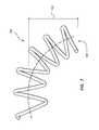
- FIG. 7is a side view of an embodiment of the first coil having a lateral bias at the distal end.
- each of the expressions “at least one of A, B and C,” “at least one of A, B, or C,” “one or more of A, B, and C,” “one or more of A, B, or C” and “A, B, and/or C”means A alone, B alone, C alone, A and B together, A and C together, B and C together, or A, B and C together.
- distal and proximalwill be used to describe the opposing axial ends of the inventive balloon catheter, as well as the axial ends of various component features.
- distalis used in its conventional sense to refer to the end of the apparatus (or component thereof) that is furthest from the operator during use of the apparatus.
- proximalis used in its conventional sense to refer to the end of the apparatus (or component thereof) that is closest to the operator during use.
- a cathetermay have a distal end and a proximal end, with the proximal end designating the end closest to the operator heart during an operation, such as a handle, and the distal end designating an opposite end of the catheter, such as treatment tip.
- distalrefers to a direction that is generally away from the operator along the apparatus during use and the term “proximally” refers to a direction that is generally toward the operator along the apparatus.
- FIG. 1illustrates a side view of a distal end 102 of a variable stiffness catheter 100 .
- FIG. 2is a cross-sectional view of the variable stiffness catheter 100 of FIG. 1 .
- the variable stiffness catheter 100is comprised of an outer layer 104 , an inner layer 106 , a first coil 108 , and a second coil 110 .
- the outer layer 104has an outer surface 112 and an inner surface 114 defining a bore.
- the inner layer 106is disposed within the bore of the outer layer 104 and is coaxial with the outer layer 104 .
- the inner layer 106has an outer surface 116 and an inner surface 118 defining a bore of the variable stiffness catheter 100 .
- the outer surface 116 of the inner layer 106faces the inner surface 114 of the outer layer 104 .
- FIG. 3is a side view of the first coil 108 .
- the first coil 108is comprised of a first wire 120 wound into a first helix 300 about a first helical axis 306 .
- the first helix 300has a plurality of turns 302 having a gap 304 between adjacent turns 302 . Each turn 302 of the first helix 300 is separated by a pitch 308 distance.
- the first wire 120has a cross section 310 defined by a plane cutting through the first wire 120 perpendicular to its axis.
- the cross section 310is a circle, although other patterns are possible.
- the cross section 310may be rectangular, square, or other shape.
- the cross section 310may vary along the length of the wire.
- the first wire 120may be comprised of stainless steel, although other materials such as nickel titanium alloys and stiff polymers are suitable for use as the wire.
- the first coil 108is disposed between the inner surface 114 of the outer layer 104 and the outer surface 116 of the inner layer 106 .
- the first coil 108is fixed in place relative to the outer cylindrical layer 104 and the inner cylindrical layer 106 .
- the first coil 108may be bonded to the inner surface 114 of the outer layer 104 and the outer surface 116 of the inner layer 106 to fix the first coil 108 in place.
- FIG. 4is a side view of the second coil 110 .
- the second coil 110is comprised of a second wire 122 wound into a helix 400 about a second helical axis 402 .
- the second coil 110has a pitch 408 that is substantially the same as the pitch 308 of the first coil 108 , such that the second wire 122 may be disposed in the gap 304 between adjacent turns 302 of the first coil 108 without interfering with the first wire 120 .
- the second coil 110is disposed between the inner surface 114 of the outer layer 104 and the outer surface 116 of the inner layer 106 with the second wire 122 lying in the gap 304 between adjacent turns 304 of the first coil 108 .
- the second coil 110is not fixed relative to the outer layer 104 and the inner layer 106 and is constrained in movement by the first wire 108 , the outer layer 104 , and the inner layer 106 .
- the second coil 110is rotatable about the second helical axis 402 relative to the outer layer 104 , the inner layer 106 , and the first coil 108 .
- the second coil 110rotates about the second helical axis 402 , the second coil 110 translates axially relative to the first coil 108 .
- Rotating the second coil 110 in a first directionwill cause the second coil 110 to translate distally, while rotation of the second coil 110 in the opposite direction will cause the second coil 110 to translate proximally.
- the second wire 122may have a second cross section 406 that is substantially the same as the first cross section 306 as shown in FIG. 4 .
- the cross section 406 of the second wire 122is shorter in a radial direction than the cross section 306 of the first wire 120 . Having a shorter cross section 406 reduces the resistance to rotation of the second coil 110 relative to the inner surface 114 of the outer layer 104 and the outer surface 116 of the inner layer 106 .
- the second wire 122may be comprised of stainless steel, although other materials such as nickel titanium alloys and stiff polymers.
- the second wire 122may comprise a different material than the first wire 120 .
- the first wire 120could be comprised of a nickel titanium alloy and the second wire 122 could be comprised of stainless steel.
- the variable stiffness catheter 100has a stiffness along its length that is equal to the combined stiffness of the inner layer 106 , the outer layer 104 , the first coil 108 , and the second coil 110 .
- a region of reduced stiffnessis present in the region distal to the distal end 410 of the second coil 110 .
- the variable stiffness catheter 100has a first region 502 proximal to the distal end 410 of the second coil 110 having a higher stiffness and a second region 500 distal to the distal end 410 of the second coil 110 having a lower stiffness, as shown in FIG. 5 .
- FIG. 5shows a longitudinal cross section of the distal end 102 of the variable stiffness catheter 100 with the second coil 110 being displaced proximally relative to the first coil 108 .
- the second region 500 of the variable stiffness catheter 100can be lengthened by further moving the distal end 410 of the second coil 110 distally.
- the length of the second region 500can be increased by moving the distal end 410 of the second coil 110 distally.
- FIG. 6illustrates another embodiment of a variable stiffness catheter 600 .
- This embodimentis similar to the previously described embodiment of FIG. 1 and is comprised of an outer layer 602 , an inner layer 604 , a first coil 606 , a second coil 608 , and a tube 610 .
- a distal end 618 of the tube 610is coupled to a proximal end 615 of the second coil 608 .
- the tube 610has an outside diameter 614 greater than an inside diameter 616 of the first coil 606 . To avoid interference between the first coil 606 and the tube 610 , first coil 606 ends prior to the distal end 618 of the tube 610 .
- the tube 610may have an outside diameter 614 less than the inside diameter 616 of the first coil 606 such that the tube 610 is able to pass within the first coil 606 .
- the tube 610has a greater torsional stiffness than the second coil 608 and is used to transmit torque over a greater distance than the second coil 608 alone.
- the proximal end (not shown) of the tube 610is disposed proximate the proximal end of the variable stiffness catheter 600 and transmits relative rotation of the tube 610 near the proximal end of the variable length catheter 600 to the second coil 608 disposed at the distal end of the variable length catheter 600 .
- the tube 610may be comprised of stainless steel, although other materials such as nickel titanium alloys and stiff polymers are suitable for use as the tube.
- FIG. 7illustrates a longitudinal cross section of an alternative embodiment of the first coil 700 .
- the first coil 700is self-biased to have a lateral displacement 702 at its distal end 704 .
- the second coilis biased to be substantially straight.
- the variable stiffness catheter 100is substantially straight.
- the bias of the first coil 700causes the distal end of the variable stiffness catheter 100 to deflect in the direction of the bias. This allows the variable stiffness catheter 100 to have a variable curve depending on the needs of the user.
- the inner surface 114 of the outer layer 104may extend into the gap between adjacent turns of the first coil 108 .
- the inner surface 114 of the outer layer 104may have a helical groove 550 in the gap for receiving the second coil 110 .
- the outer surface of the inner layer 106may extend into the gap between adjacent coils of the first coil 108 .
- the inner layer 106may have a helical groove 552 in the gap for receiving the second coil 110 .
- the inner layer and the outer layermay be comprised of the same material and form an integral wall having the coils disposed within the wall.
- the first coilis fixed within the wall and the second coil is free to rotate relative to the first coil and the integral wall.
- the helical channelis formed in the integral wall in the gap between adjacent turns of the first coil.
- the second coiltravels in the helical channel when rotated relative to the first coil and the integral wall.
- the channelmay be formed by coating the second coil with a release compound allowing the integral wall to be formed with the second wire in place. Because the second coil is coated with the release compound it may be rotated within the integral wall since it is not adhered to the integral wall lie the first coil.
- a helical plug having a cross section larger than the second coilmay be coated with a release compound when the integral wall is formed. The helical plug may then be removed leaving a channel having a cross section greater than the second coil. The second coil may then be threaded into the helical channel left by the helical plug.
Landscapes
- Health & Medical Sciences (AREA)
- Life Sciences & Earth Sciences (AREA)
- Biophysics (AREA)
- Pulmonology (AREA)
- Engineering & Computer Science (AREA)
- Anesthesiology (AREA)
- Biomedical Technology (AREA)
- Heart & Thoracic Surgery (AREA)
- Hematology (AREA)
- Animal Behavior & Ethology (AREA)
- General Health & Medical Sciences (AREA)
- Public Health (AREA)
- Veterinary Medicine (AREA)
- Media Introduction/Drainage Providing Device (AREA)
Abstract
Description
Claims (16)
Priority Applications (2)
| Application Number | Priority Date | Filing Date | Title |
|---|---|---|---|
| US14/207,294US9370639B2 (en) | 2013-03-12 | 2014-03-12 | Variable stiffness catheter |
| US15/095,465US9861782B2 (en) | 2013-03-12 | 2016-04-11 | Variable stiffness catheter |
Applications Claiming Priority (2)
| Application Number | Priority Date | Filing Date | Title |
|---|---|---|---|
| US201361777447P | 2013-03-12 | 2013-03-12 | |
| US14/207,294US9370639B2 (en) | 2013-03-12 | 2014-03-12 | Variable stiffness catheter |
Related Child Applications (1)
| Application Number | Title | Priority Date | Filing Date |
|---|---|---|---|
| US15/095,465DivisionUS9861782B2 (en) | 2013-03-12 | 2016-04-11 | Variable stiffness catheter |
Publications (2)
| Publication Number | Publication Date |
|---|---|
| US20150258306A1 US20150258306A1 (en) | 2015-09-17 |
| US9370639B2true US9370639B2 (en) | 2016-06-21 |
Family
ID=54067826
Family Applications (2)
| Application Number | Title | Priority Date | Filing Date |
|---|---|---|---|
| US14/207,294ActiveUS9370639B2 (en) | 2013-03-12 | 2014-03-12 | Variable stiffness catheter |
| US15/095,465Active2034-06-26US9861782B2 (en) | 2013-03-12 | 2016-04-11 | Variable stiffness catheter |
Family Applications After (1)
| Application Number | Title | Priority Date | Filing Date |
|---|---|---|---|
| US15/095,465Active2034-06-26US9861782B2 (en) | 2013-03-12 | 2016-04-11 | Variable stiffness catheter |
Country Status (1)
| Country | Link |
|---|---|
| US (2) | US9370639B2 (en) |
Cited By (30)
| Publication number | Priority date | Publication date | Assignee | Title |
|---|---|---|---|---|
| US10179224B2 (en) | 2016-02-24 | 2019-01-15 | Incept, Llc | Enhanced flexibility neurovascular catheter with tensile support |
| US10213582B2 (en) | 2013-12-23 | 2019-02-26 | Route 92 Medical, Inc. | Methods and systems for treatment of acute ischemic stroke |
| US10456555B2 (en) | 2015-02-04 | 2019-10-29 | Route 92 Medical, Inc. | Rapid aspiration thrombectomy system and method |
| US10653426B2 (en) | 2017-01-06 | 2020-05-19 | Incept, Llc | Thromboresistant coatings for aneurysm treatment devices |
| US10653434B1 (en) | 2018-05-01 | 2020-05-19 | Imperative Care, Inc. | Devices and methods for removing obstructive material from an intravascular site |
| US10765307B2 (en) | 2003-04-01 | 2020-09-08 | Boston Scientific Scimed, Inc. | Endoscopic imaging system |
| US11020133B2 (en) | 2017-01-10 | 2021-06-01 | Route 92 Medical, Inc. | Aspiration catheter systems and methods of use |
| US11065018B2 (en) | 2019-12-18 | 2021-07-20 | Imperative Care, Inc. | Methods and systems for advancing a catheter to a target site |
| US11065019B1 (en) | 2015-02-04 | 2021-07-20 | Route 92 Medical, Inc. | Aspiration catheter systems and methods of use |
| US11123522B2 (en) | 2015-01-20 | 2021-09-21 | Q'apel Medical, Llc | Tubular structures with variable support |
| US11134859B2 (en) | 2019-10-15 | 2021-10-05 | Imperative Care, Inc. | Systems and methods for multivariate stroke detection |
| US11197977B2 (en) | 2017-12-15 | 2021-12-14 | Perfuze Limited | Catheters and devices and systems incorporating such catheters |
| US11207497B1 (en) | 2020-08-11 | 2021-12-28 | Imperative Care, Inc. | Catheter with enhanced tensile strength |
| US11224449B2 (en) | 2015-07-24 | 2022-01-18 | Route 92 Medical, Inc. | Anchoring delivery system and methods |
| US11229770B2 (en) | 2018-05-17 | 2022-01-25 | Route 92 Medical, Inc. | Aspiration catheter systems and methods of use |
| US11395665B2 (en) | 2018-05-01 | 2022-07-26 | Incept, Llc | Devices and methods for removing obstructive material, from an intravascular site |
| US11439799B2 (en) | 2019-12-18 | 2022-09-13 | Imperative Care, Inc. | Split dilator aspiration system |
| US11446469B2 (en) | 2016-07-13 | 2022-09-20 | Perfuze Limited | High flexibility, kink resistant catheter shaft |
| US11471582B2 (en) | 2018-07-06 | 2022-10-18 | Incept, Llc | Vacuum transfer tool for extendable catheter |
| US11511085B2 (en) | 2015-11-18 | 2022-11-29 | Heraeus Deutschland GmbH & Co. KG | Torque coil and method |
| US11517335B2 (en) | 2018-07-06 | 2022-12-06 | Incept, Llc | Sealed neurovascular extendable catheter |
| US11553935B2 (en) | 2019-12-18 | 2023-01-17 | Imperative Care, Inc. | Sterile field clot capture module for use in thrombectomy system |
| US11565082B2 (en) | 2020-03-10 | 2023-01-31 | Imperative Care, Inc. | Enhanced flexibility neurovascular catheter |
| US11766539B2 (en) | 2019-03-29 | 2023-09-26 | Incept, Llc | Enhanced flexibility neurovascular catheter |
| US12076503B2 (en) | 2016-07-27 | 2024-09-03 | Q'Apel Medical, Inc. | Tubular structures with variable support |
| US12144940B2 (en) | 2020-10-09 | 2024-11-19 | Route 92 Medical, Inc. | Aspiration catheter systems and methods of use |
| US12194247B2 (en) | 2017-01-20 | 2025-01-14 | Route 92 Medical, Inc. | Single operator intracranial medical device delivery systems and methods of use |
| US12232838B2 (en) | 2021-08-12 | 2025-02-25 | Imperative Care, Inc. | Method of robotically performing a neurovascular procedure |
| US12262911B2 (en) | 2011-08-05 | 2025-04-01 | Route 92 Medical, Inc. | Methods and systems for treatment of acute ischemic stroke |
| USD1077996S1 (en) | 2021-10-18 | 2025-06-03 | Imperative Care, Inc. | Inline fluid filter |
Families Citing this family (15)
| Publication number | Priority date | Publication date | Assignee | Title |
|---|---|---|---|---|
| US7771411B2 (en) | 2004-09-24 | 2010-08-10 | Syntheon, Llc | Methods for operating a selective stiffening catheter |
| US9814372B2 (en) | 2007-06-27 | 2017-11-14 | Syntheon, Llc | Torque-transmitting, variably-flexible, locking insertion device and method for operating the insertion device |
| US10123683B2 (en) | 2006-03-02 | 2018-11-13 | Syntheon, Llc | Variably flexible insertion device and method for variably flexing an insertion device |
| CA2994262C (en) | 2015-07-30 | 2023-09-19 | Gmedix, Inc. | Coronary guide catheter |
| US20170106170A1 (en) | 2015-10-19 | 2017-04-20 | Biocardia, Inc. | Multi-Directional Steerable Catheter |
| US10610666B2 (en)* | 2015-12-28 | 2020-04-07 | Covidien Lp | Multi-filament catheter |
| WO2017159007A1 (en)* | 2016-03-18 | 2017-09-21 | テルモ株式会社 | Catheter |
| WO2018185917A1 (en)* | 2017-04-06 | 2018-10-11 | 朝日インテック株式会社 | Tubular body and tubular body having catheter |
| US10751507B2 (en) | 2017-04-10 | 2020-08-25 | Syn Variflex, Llc | Thermally controlled variable-flexibility catheters and methods of manufacturing same |
| US20200359901A1 (en)* | 2017-08-18 | 2020-11-19 | Vena Medical Holdings Corp. | Device and method for imaging vasculature |
| WO2019038073A1 (en)* | 2017-08-22 | 2019-02-28 | Koninklijke Philips N.V. | Adjustable flexibility/stiffness intraluminal device |
| EP4013480B1 (en)* | 2019-08-13 | 2025-09-24 | Reflow Medical, Inc. | Support catheter |
| JP7714349B2 (en)* | 2021-03-01 | 2025-07-29 | 株式会社カネカ | catheter |
| CN116570817B (en)* | 2023-07-12 | 2023-09-26 | 深圳先进技术研究院 | Magnetic drive catheter with variable rigidity |
| CN116992702B (en)* | 2023-09-29 | 2023-12-22 | 季华实验室 | Methods, devices, equipment and media for determining the meshing stiffness of the back side of the internal gear auxiliary teeth |
Citations (12)
| Publication number | Priority date | Publication date | Assignee | Title |
|---|---|---|---|---|
| US4236509A (en) | 1976-12-28 | 1980-12-02 | Nagashige Takahashi | Curving device in an endoscope |
| US4728319A (en) | 1986-03-20 | 1988-03-01 | Helmut Masch | Intravascular catheter |
| US5234437A (en) | 1991-12-12 | 1993-08-10 | Target Therapeutics, Inc. | Detachable pusher-vasoocclusion coil assembly with threaded coupling |
| US5271415A (en) | 1992-01-28 | 1993-12-21 | Baxter International Inc. | Guidewire extension system |
| US5409470A (en) | 1993-05-07 | 1995-04-25 | C. R. Bard, Inc. | Dilatation catheter and guidewire with threaded tip connection |
| US5454795A (en) | 1994-06-27 | 1995-10-03 | Target Therapeutics, Inc. | Kink-free spiral-wound catheter |
| US5951539A (en)* | 1997-06-10 | 1999-09-14 | Target Therpeutics, Inc. | Optimized high performance multiple coil spiral-wound vascular catheter |
| US20010041881A1 (en)* | 1999-07-28 | 2001-11-15 | Scimed Life Systems, Inc. | Catheter having continuous lattice and coil reinforcement |
| US6890329B2 (en) | 1999-06-15 | 2005-05-10 | Cryocath Technologies Inc. | Defined deflection structure |
| US20060129130A1 (en) | 2004-11-18 | 2006-06-15 | Tal Michael G | Sheath/catheter system with controlled hardness and flexibility |
| US8246536B2 (en) | 2006-04-26 | 2012-08-21 | Hoya Corporation | Treatment tool insertion channel of endoscope |
| US20120277729A1 (en) | 2011-04-29 | 2012-11-01 | Melsheimer Jeffry S | Catheter having a selectively variable degree of flexibility |
Family Cites Families (2)
| Publication number | Priority date | Publication date | Assignee | Title |
|---|---|---|---|---|
| US5176660A (en)* | 1989-10-23 | 1993-01-05 | Cordis Corporation | Catheter having reinforcing strands |
| US7850623B2 (en)* | 2005-10-27 | 2010-12-14 | Boston Scientific Scimed, Inc. | Elongate medical device with continuous reinforcement member |
- 2014
- 2014-03-12USUS14/207,294patent/US9370639B2/enactiveActive
- 2016
- 2016-04-11USUS15/095,465patent/US9861782B2/enactiveActive
Patent Citations (13)
| Publication number | Priority date | Publication date | Assignee | Title |
|---|---|---|---|---|
| US4236509A (en) | 1976-12-28 | 1980-12-02 | Nagashige Takahashi | Curving device in an endoscope |
| US4728319A (en) | 1986-03-20 | 1988-03-01 | Helmut Masch | Intravascular catheter |
| US5234437A (en) | 1991-12-12 | 1993-08-10 | Target Therapeutics, Inc. | Detachable pusher-vasoocclusion coil assembly with threaded coupling |
| US5271415A (en) | 1992-01-28 | 1993-12-21 | Baxter International Inc. | Guidewire extension system |
| US5409470A (en) | 1993-05-07 | 1995-04-25 | C. R. Bard, Inc. | Dilatation catheter and guidewire with threaded tip connection |
| US5695483A (en) | 1994-06-27 | 1997-12-09 | Target Therapeutics Inc. | Kink-free spiral-wound catheter |
| US5454795A (en) | 1994-06-27 | 1995-10-03 | Target Therapeutics, Inc. | Kink-free spiral-wound catheter |
| US5951539A (en)* | 1997-06-10 | 1999-09-14 | Target Therpeutics, Inc. | Optimized high performance multiple coil spiral-wound vascular catheter |
| US6890329B2 (en) | 1999-06-15 | 2005-05-10 | Cryocath Technologies Inc. | Defined deflection structure |
| US20010041881A1 (en)* | 1999-07-28 | 2001-11-15 | Scimed Life Systems, Inc. | Catheter having continuous lattice and coil reinforcement |
| US20060129130A1 (en) | 2004-11-18 | 2006-06-15 | Tal Michael G | Sheath/catheter system with controlled hardness and flexibility |
| US8246536B2 (en) | 2006-04-26 | 2012-08-21 | Hoya Corporation | Treatment tool insertion channel of endoscope |
| US20120277729A1 (en) | 2011-04-29 | 2012-11-01 | Melsheimer Jeffry S | Catheter having a selectively variable degree of flexibility |
Cited By (83)
| Publication number | Priority date | Publication date | Assignee | Title |
|---|---|---|---|---|
| US10765307B2 (en) | 2003-04-01 | 2020-09-08 | Boston Scientific Scimed, Inc. | Endoscopic imaging system |
| US11324395B2 (en) | 2003-04-01 | 2022-05-10 | Boston Scientific Scimed, Inc. | Endoscopic imaging system |
| US12262911B2 (en) | 2011-08-05 | 2025-04-01 | Route 92 Medical, Inc. | Methods and systems for treatment of acute ischemic stroke |
| US12343036B2 (en) | 2011-08-05 | 2025-07-01 | Route 92 Medical, Inc. | Methods and systems for treatment of acute ischemic stroke |
| US10569049B2 (en) | 2013-12-23 | 2020-02-25 | Route 92 Medical, Inc. | Methods and systems for treatment of acute ischemic stroke |
| US10471233B2 (en) | 2013-12-23 | 2019-11-12 | Route 92 Medical, Inc. | Methods and systems for treatment of acute ischemic stroke |
| US12115320B2 (en) | 2013-12-23 | 2024-10-15 | Route 92 Medical, Inc. | Methods and systems for treatment of acute ischemic stroke |
| US12343480B2 (en) | 2013-12-23 | 2025-07-01 | Route 92 Medical, Inc. | Methods and systems for treatment of acute ischemic stroke |
| US10213582B2 (en) | 2013-12-23 | 2019-02-26 | Route 92 Medical, Inc. | Methods and systems for treatment of acute ischemic stroke |
| US10864351B2 (en) | 2013-12-23 | 2020-12-15 | Route 92 Medical, Inc. | Methods and systems for treatment of acute ischemic stroke |
| US11318282B2 (en) | 2013-12-23 | 2022-05-03 | Route 92 Medical, Inc. | Methods and systems for treatment of acute ischemic stroke |
| US11534575B2 (en) | 2013-12-23 | 2022-12-27 | Route 92 Medical, Inc. | Methods and systems for treatment of acute ischemic stroke |
| US12064572B2 (en) | 2015-01-20 | 2024-08-20 | Q'Apel Medical, Inc. | Tubular structures with variable support |
| US11123522B2 (en) | 2015-01-20 | 2021-09-21 | Q'apel Medical, Llc | Tubular structures with variable support |
| US11793529B2 (en) | 2015-02-04 | 2023-10-24 | Route 92 Medical, Inc. | Aspiration catheter systems and methods of use |
| US11633571B2 (en) | 2015-02-04 | 2023-04-25 | Route 92 Medical, Inc. | Rapid aspiration thrombectomy system and method |
| US11576691B2 (en) | 2015-02-04 | 2023-02-14 | Route 92 Medical, Inc. | Aspiration catheter systems and methods of use |
| US11633570B2 (en) | 2015-02-04 | 2023-04-25 | Route 92 Medical, Inc. | Rapid aspiration thrombectomy system and method |
| US11395903B2 (en) | 2015-02-04 | 2022-07-26 | Route 92 Medical, Inc. | Rapid aspiration thrombectomy system and method |
| US11383064B2 (en) | 2015-02-04 | 2022-07-12 | Route 92 Medical, Inc. | Rapid aspiration thrombectomy system and method |
| US11065019B1 (en) | 2015-02-04 | 2021-07-20 | Route 92 Medical, Inc. | Aspiration catheter systems and methods of use |
| US10485952B2 (en) | 2015-02-04 | 2019-11-26 | Route 92 Medical, Inc. | Rapid aspiration thrombectomy system and method |
| US10456555B2 (en) | 2015-02-04 | 2019-10-29 | Route 92 Medical, Inc. | Rapid aspiration thrombectomy system and method |
| US11793972B2 (en) | 2015-02-04 | 2023-10-24 | Route 92 Medical, Inc. | Rapid aspiration thrombectomy system and method |
| US11305094B2 (en) | 2015-02-04 | 2022-04-19 | Route 92 Medical, Inc. | Rapid aspiration thrombectomy system and method |
| US11185664B2 (en) | 2015-02-04 | 2021-11-30 | Route 92 Medical, Inc. | Rapid aspiration thrombectomy system and method |
| US11806032B2 (en) | 2015-02-04 | 2023-11-07 | Route 92 Medical, Inc. | Aspiration catheter systems and methods of use |
| US11224721B2 (en) | 2015-02-04 | 2022-01-18 | Route 92 Medical, Inc. | Rapid aspiration thrombectomy system and method |
| US11224450B2 (en) | 2015-02-04 | 2022-01-18 | Route 92 Medical, Inc. | Aspiration catheter systems and methods of use |
| US12213688B2 (en) | 2015-07-24 | 2025-02-04 | Route 92 Medical, Inc. | Anchoring delivery system and methods |
| US11224449B2 (en) | 2015-07-24 | 2022-01-18 | Route 92 Medical, Inc. | Anchoring delivery system and methods |
| US11511085B2 (en) | 2015-11-18 | 2022-11-29 | Heraeus Deutschland GmbH & Co. KG | Torque coil and method |
| US10183147B2 (en) | 2016-02-24 | 2019-01-22 | Incept, Llc | Neurovascular catheter extension segment |
| US10661053B2 (en) | 2016-02-24 | 2020-05-26 | Incept, Llc | Method of pulsatile neurovascular aspiration with telescoping catheter |
| US11147949B2 (en) | 2016-02-24 | 2021-10-19 | Incept, Llc | Method of making an enhanced flexibility neurovascular catheter |
| US10183145B2 (en) | 2016-02-24 | 2019-01-22 | Incept, Llc | Enhanced flexibility neurovascular catheter |
| US10183146B2 (en) | 2016-02-24 | 2019-01-22 | Incept, Llc | Method of making an enhanced flexibility neurovascular catheter |
| US10835711B2 (en) | 2016-02-24 | 2020-11-17 | Incept, Llc | Telescoping neurovascular catheter with enlargeable distal opening |
| US12343479B2 (en) | 2016-02-24 | 2025-07-01 | Incept, Llc | Neurovascular catheter |
| US10441745B2 (en) | 2016-02-24 | 2019-10-15 | Incept, Llc | Neurovascular catheter with enlargeable distal end |
| US10179224B2 (en) | 2016-02-24 | 2019-01-15 | Incept, Llc | Enhanced flexibility neurovascular catheter with tensile support |
| US11446469B2 (en) | 2016-07-13 | 2022-09-20 | Perfuze Limited | High flexibility, kink resistant catheter shaft |
| US20220379078A1 (en)* | 2016-07-13 | 2022-12-01 | Perfuze Limited | High flexibility, kink resistant catheter shaft |
| US12076503B2 (en) | 2016-07-27 | 2024-09-03 | Q'Apel Medical, Inc. | Tubular structures with variable support |
| US10653426B2 (en) | 2017-01-06 | 2020-05-19 | Incept, Llc | Thromboresistant coatings for aneurysm treatment devices |
| US11224434B2 (en) | 2017-01-06 | 2022-01-18 | Incept, Llc | Thromboresistant coatings for aneurysm treatment devices |
| US11903588B2 (en) | 2017-01-06 | 2024-02-20 | Incept, Llc | Thromboresistant coatings for aneurysm treatment devices |
| US11399852B2 (en) | 2017-01-10 | 2022-08-02 | Route 92 Medical, Inc. | Aspiration catheter systems and methods of use |
| US12295595B2 (en) | 2017-01-10 | 2025-05-13 | Route 92 Medical, Inc. | Aspiration catheter systems and methods of use |
| US11020133B2 (en) | 2017-01-10 | 2021-06-01 | Route 92 Medical, Inc. | Aspiration catheter systems and methods of use |
| US12194247B2 (en) | 2017-01-20 | 2025-01-14 | Route 92 Medical, Inc. | Single operator intracranial medical device delivery systems and methods of use |
| US11197977B2 (en) | 2017-12-15 | 2021-12-14 | Perfuze Limited | Catheters and devices and systems incorporating such catheters |
| US11395665B2 (en) | 2018-05-01 | 2022-07-26 | Incept, Llc | Devices and methods for removing obstructive material, from an intravascular site |
| US10835272B2 (en) | 2018-05-01 | 2020-11-17 | Incept, Llc | Devices and methods for removing obstructive material from an intravascular site |
| US10786270B2 (en) | 2018-05-01 | 2020-09-29 | Imperative Care, Inc. | Neurovascular aspiration catheter with elliptical aspiration port |
| US10653434B1 (en) | 2018-05-01 | 2020-05-19 | Imperative Care, Inc. | Devices and methods for removing obstructive material from an intravascular site |
| US11123090B2 (en) | 2018-05-01 | 2021-09-21 | Incept, Llc | Neurovascular catheter having atraumatic angled tip |
| US11311303B2 (en) | 2018-05-01 | 2022-04-26 | Incept, Llc | Enhanced flexibility neurovascular catheter with tensile support |
| US12042160B2 (en) | 2018-05-01 | 2024-07-23 | Incept, Llc | Catheter having angled tip |
| US11607523B2 (en) | 2018-05-17 | 2023-03-21 | Route 92 Medical, Inc. | Aspiration catheter systems and methods of use |
| US11925770B2 (en) | 2018-05-17 | 2024-03-12 | Route 92 Medical, Inc. | Aspiration catheter systems and methods of use |
| US12383702B2 (en) | 2018-05-17 | 2025-08-12 | Route 92 Medical, Inc. | Aspiration catheter systems and methods of use |
| US11229770B2 (en) | 2018-05-17 | 2022-01-25 | Route 92 Medical, Inc. | Aspiration catheter systems and methods of use |
| US11850349B2 (en) | 2018-07-06 | 2023-12-26 | Incept, Llc | Vacuum transfer tool for extendable catheter |
| US11517335B2 (en) | 2018-07-06 | 2022-12-06 | Incept, Llc | Sealed neurovascular extendable catheter |
| US11471582B2 (en) | 2018-07-06 | 2022-10-18 | Incept, Llc | Vacuum transfer tool for extendable catheter |
| US11766539B2 (en) | 2019-03-29 | 2023-09-26 | Incept, Llc | Enhanced flexibility neurovascular catheter |
| US11134859B2 (en) | 2019-10-15 | 2021-10-05 | Imperative Care, Inc. | Systems and methods for multivariate stroke detection |
| US11504020B2 (en) | 2019-10-15 | 2022-11-22 | Imperative Care, Inc. | Systems and methods for multivariate stroke detection |
| US11439799B2 (en) | 2019-12-18 | 2022-09-13 | Imperative Care, Inc. | Split dilator aspiration system |
| US11457936B2 (en) | 2019-12-18 | 2022-10-04 | Imperative Care, Inc. | Catheter system for treating thromboembolic disease |
| US11819228B2 (en) | 2019-12-18 | 2023-11-21 | Imperative Care, Inc. | Methods and systems for treating a pulmonary embolism |
| US11253277B2 (en) | 2019-12-18 | 2022-02-22 | Imperative Care, Inc. | Systems for accessing a central pulmonary artery |
| US11065018B2 (en) | 2019-12-18 | 2021-07-20 | Imperative Care, Inc. | Methods and systems for advancing a catheter to a target site |
| US11553935B2 (en) | 2019-12-18 | 2023-01-17 | Imperative Care, Inc. | Sterile field clot capture module for use in thrombectomy system |
| US11633272B2 (en) | 2019-12-18 | 2023-04-25 | Imperative Care, Inc. | Manually rotatable thrombus engagement tool |
| US11638637B2 (en) | 2019-12-18 | 2023-05-02 | Imperative Care, Inc. | Method of removing embolic material with thrombus engagement tool |
| US11565082B2 (en) | 2020-03-10 | 2023-01-31 | Imperative Care, Inc. | Enhanced flexibility neurovascular catheter |
| US11207497B1 (en) | 2020-08-11 | 2021-12-28 | Imperative Care, Inc. | Catheter with enhanced tensile strength |
| US12144940B2 (en) | 2020-10-09 | 2024-11-19 | Route 92 Medical, Inc. | Aspiration catheter systems and methods of use |
| US12232838B2 (en) | 2021-08-12 | 2025-02-25 | Imperative Care, Inc. | Method of robotically performing a neurovascular procedure |
| US12376928B2 (en) | 2021-08-12 | 2025-08-05 | Imperative Care, Inc. | Catheter drive system for supra-aortic access |
| USD1077996S1 (en) | 2021-10-18 | 2025-06-03 | Imperative Care, Inc. | Inline fluid filter |
Also Published As
| Publication number | Publication date |
|---|---|
| US20150258306A1 (en) | 2015-09-17 |
| US9861782B2 (en) | 2018-01-09 |
| US20160220787A1 (en) | 2016-08-04 |
Similar Documents
| Publication | Publication Date | Title |
|---|---|---|
| US9370639B2 (en) | Variable stiffness catheter | |
| AU2024201009B2 (en) | Micro-fabricated medical device having a non-helical cut arrangement | |
| AU2017327825B2 (en) | Integrated coil vascular devices | |
| AU2017217879B2 (en) | Intravascular treatment site access | |
| JP6364016B2 (en) | Coaxial bidirectional catheter | |
| JP7003077B2 (en) | catheter | |
| US5372144A (en) | Navigability improved guidewire construction and method of using same | |
| US5497785A (en) | Catheter advancing guidewire and method for making same | |
| US20040215109A1 (en) | Helical guidewire | |
| US10220189B2 (en) | High-torque guidewires and methods for making and using them | |
| JP7155269B2 (en) | Guided extension catheter | |
| US10426927B2 (en) | Telescoping catheters and methods for use | |
| JP2007503952A (en) | Method of using a deflectable medical therapy delivery device having a common lumen profile | |
| US20150105721A1 (en) | Steerable medical devices | |
| JP2007503920A (en) | Device for providing deflectable medical therapy having a common lumen profile | |
| JP3179894U (en) | catheter | |
| US20190015629A1 (en) | Multi-Lumen Catheters for Small Body Vessel Applications | |
| US20250261932A1 (en) | Micro-fabricated medical device having a non-helical cut arrangement | |
| HK40055805A (en) | Micro-fabricated medical device having a non-helical cut arrangement | |
| HK40055805B (en) | Micro-fabricated medical device having a non-helical cut arrangement | |
| WO2024243288A1 (en) | Intravascular device with nested hypotube configuration | |
| EP4291275A1 (en) | Catheter and manufacturing method therefor |
Legal Events
| Date | Code | Title | Description |
|---|---|---|---|
| AS | Assignment | Owner name:COOK MEDICAL TECHNOLOGIES LLC, INDIANA Free format text:ASSIGNMENT OF ASSIGNORS INTEREST;ASSIGNORS:PLASSMAN, TREVOR;CAGE, LOGAN MICHAEL;SIGNING DATES FROM 20130328 TO 20130329;REEL/FRAME:036109/0834 Owner name:COOK INCORPORATED, INDIANA Free format text:ASSIGNMENT OF ASSIGNORS INTEREST;ASSIGNORS:PLASSMAN, TREVOR;CAGE, LOGAN MICHAEL;SIGNING DATES FROM 20130328 TO 20130329;REEL/FRAME:036109/0834 | |
| AS | Assignment | Owner name:COOK MEDICAL TECHNOLOGIES LLC, INDIANA Free format text:ASSIGNMENT OF ASSIGNORS INTEREST;ASSIGNOR:COOK INCORPORATED;REEL/FRAME:036297/0933 Effective date:20130401 Owner name:COOK INCORPORATED, INDIANA Free format text:ASSIGNMENT OF ASSIGNORS INTEREST;ASSIGNORS:PLASSMAN, TREVOR;CAGE, LOGAN MICHAEL;SIGNING DATES FROM 20130328 TO 20130329;REEL/FRAME:036297/0922 | |
| STCF | Information on status: patent grant | Free format text:PATENTED CASE | |
| MAFP | Maintenance fee payment | Free format text:PAYMENT OF MAINTENANCE FEE, 4TH YEAR, LARGE ENTITY (ORIGINAL EVENT CODE: M1551); ENTITY STATUS OF PATENT OWNER: LARGE ENTITY Year of fee payment:4 | |
| MAFP | Maintenance fee payment | Free format text:PAYMENT OF MAINTENANCE FEE, 8TH YEAR, LARGE ENTITY (ORIGINAL EVENT CODE: M1552); ENTITY STATUS OF PATENT OWNER: LARGE ENTITY Year of fee payment:8 | |
| AS | Assignment | Owner name:WILMINGTON TRUST, NATIONAL ASSOCIATION, AS COLLATERAL AGENT, DELAWARE Free format text:SECURITY INTEREST;ASSIGNOR:COOK MEDICAL TECHNOLOGIES LLC;REEL/FRAME:066700/0277 Effective date:20240227 |