US9370443B2 - Intraocular implants and methods and kits therefor - Google Patents
Intraocular implants and methods and kits thereforDownload PDFInfo
- Publication number
- US9370443B2 US9370443B2US13/025,112US201113025112AUS9370443B2US 9370443 B2US9370443 B2US 9370443B2US 201113025112 AUS201113025112 AUS 201113025112AUS 9370443 B2US9370443 B2US 9370443B2
- Authority
- US
- United States
- Prior art keywords
- support
- canal
- poly
- schlemm
- kit
- Prior art date
- Legal status (The legal status is an assumption and is not a legal conclusion. Google has not performed a legal analysis and makes no representation as to the accuracy of the status listed.)
- Active, expires
Links
- 0CC1=*C=C1C1=CC=CC1=CChemical compoundCC1=*C=C1C1=CC=CC1=C0.000description1
Images


Classifications
- A—HUMAN NECESSITIES
- A61—MEDICAL OR VETERINARY SCIENCE; HYGIENE
- A61F—FILTERS IMPLANTABLE INTO BLOOD VESSELS; PROSTHESES; DEVICES PROVIDING PATENCY TO, OR PREVENTING COLLAPSING OF, TUBULAR STRUCTURES OF THE BODY, e.g. STENTS; ORTHOPAEDIC, NURSING OR CONTRACEPTIVE DEVICES; FOMENTATION; TREATMENT OR PROTECTION OF EYES OR EARS; BANDAGES, DRESSINGS OR ABSORBENT PADS; FIRST-AID KITS
- A61F9/00—Methods or devices for treatment of the eyes; Devices for putting in contact-lenses; Devices to correct squinting; Apparatus to guide the blind; Protective devices for the eyes, carried on the body or in the hand
- A61F9/007—Methods or devices for eye surgery
- A61F9/00781—Apparatus for modifying intraocular pressure, e.g. for glaucoma treatment
- A—HUMAN NECESSITIES
- A61—MEDICAL OR VETERINARY SCIENCE; HYGIENE
- A61F—FILTERS IMPLANTABLE INTO BLOOD VESSELS; PROSTHESES; DEVICES PROVIDING PATENCY TO, OR PREVENTING COLLAPSING OF, TUBULAR STRUCTURES OF THE BODY, e.g. STENTS; ORTHOPAEDIC, NURSING OR CONTRACEPTIVE DEVICES; FOMENTATION; TREATMENT OR PROTECTION OF EYES OR EARS; BANDAGES, DRESSINGS OR ABSORBENT PADS; FIRST-AID KITS
- A61F9/00—Methods or devices for treatment of the eyes; Devices for putting in contact-lenses; Devices to correct squinting; Apparatus to guide the blind; Protective devices for the eyes, carried on the body or in the hand
- A61F9/0008—Introducing ophthalmic products into the ocular cavity or retaining products therein
- A61F9/0017—Introducing ophthalmic products into the ocular cavity or retaining products therein implantable in, or in contact with, the eye, e.g. ocular inserts
- A—HUMAN NECESSITIES
- A61—MEDICAL OR VETERINARY SCIENCE; HYGIENE
- A61F—FILTERS IMPLANTABLE INTO BLOOD VESSELS; PROSTHESES; DEVICES PROVIDING PATENCY TO, OR PREVENTING COLLAPSING OF, TUBULAR STRUCTURES OF THE BODY, e.g. STENTS; ORTHOPAEDIC, NURSING OR CONTRACEPTIVE DEVICES; FOMENTATION; TREATMENT OR PROTECTION OF EYES OR EARS; BANDAGES, DRESSINGS OR ABSORBENT PADS; FIRST-AID KITS
- A61F2210/00—Particular material properties of prostheses classified in groups A61F2/00 - A61F2/26 or A61F2/82 or A61F9/00 or A61F11/00 or subgroups thereof
- A61F2210/0004—Particular material properties of prostheses classified in groups A61F2/00 - A61F2/26 or A61F2/82 or A61F9/00 or A61F11/00 or subgroups thereof bioabsorbable
- A—HUMAN NECESSITIES
- A61—MEDICAL OR VETERINARY SCIENCE; HYGIENE
- A61F—FILTERS IMPLANTABLE INTO BLOOD VESSELS; PROSTHESES; DEVICES PROVIDING PATENCY TO, OR PREVENTING COLLAPSING OF, TUBULAR STRUCTURES OF THE BODY, e.g. STENTS; ORTHOPAEDIC, NURSING OR CONTRACEPTIVE DEVICES; FOMENTATION; TREATMENT OR PROTECTION OF EYES OR EARS; BANDAGES, DRESSINGS OR ABSORBENT PADS; FIRST-AID KITS
- A61F2210/00—Particular material properties of prostheses classified in groups A61F2/00 - A61F2/26 or A61F2/82 or A61F9/00 or A61F11/00 or subgroups thereof
- A61F2210/0014—Particular material properties of prostheses classified in groups A61F2/00 - A61F2/26 or A61F2/82 or A61F9/00 or A61F11/00 or subgroups thereof using shape memory or superelastic materials, e.g. nitinol
- A—HUMAN NECESSITIES
- A61—MEDICAL OR VETERINARY SCIENCE; HYGIENE
- A61F—FILTERS IMPLANTABLE INTO BLOOD VESSELS; PROSTHESES; DEVICES PROVIDING PATENCY TO, OR PREVENTING COLLAPSING OF, TUBULAR STRUCTURES OF THE BODY, e.g. STENTS; ORTHOPAEDIC, NURSING OR CONTRACEPTIVE DEVICES; FOMENTATION; TREATMENT OR PROTECTION OF EYES OR EARS; BANDAGES, DRESSINGS OR ABSORBENT PADS; FIRST-AID KITS
- A61F2250/00—Special features of prostheses classified in groups A61F2/00 - A61F2/26 or A61F2/82 or A61F9/00 or A61F11/00 or subgroups thereof
- A61F2250/0058—Additional features; Implant or prostheses properties not otherwise provided for
- A61F2250/0067—Means for introducing or releasing pharmaceutical products into the body
Definitions
- the devices, kits and methods described hereinrelate generally to intraocular pressure reduction. More particularly, the devices, kits and methods relate to intraocular implants implantable into Schlemm's canal that can reduce intraocular pressure without substantially interfering with fluid flow across Schlemm's canal.
- Glaucomais a potentially blinding disease that affects over 60 million people worldwide, or about 1-2% of the population.
- glaucomais characterized by elevated intraocular pressure. Increased pressure in the eye can cause damage to the optic nerve which can lead to loss of vision if left untreated. Consistent reduction of intraocular pressure can slow down or stop progressive loss of vision associated with glaucoma.
- patientsare often diagnosed with pre-glaucoma and ocular hypertension when they exhibit symptoms likely to lead to glaucoma, such as somewhat elevated intraocular pressure, but do not yet show indications of optic nerve damage. Treatments for glaucoma, pre-glaucoma and ocular hypertension primarily seek to reduce intraocular pressure.
- Aqueous humor or fluidis a clear, colorless fluid that is continuously replenished in the eye.
- Aqueous humoris produced by the ciliary body, and then flows out primarily through the eye's trabecular meshwork.
- the trabecular meshworkextends circumferentially around the eye at the anterior chamber angle, or drainage angle, which is formed at the intersection between the peripheral iris or iris root, the anterior sclera or scleral spur and the peripheral cornea.
- the trabecular meshworkfeeds outwardly into Schlemm's canal, a narrow circumferential passageway generally surrounding the exterior border of the trabecular meshwork.
- aqueous veins or collector channelsPositioned around and radially extending from Schlemm's canal are aqueous veins or collector channels that receive drained fluid.
- the net drainage or efflux of aqueous humorcan be reduced as a result of decreased facility of outflow, decreased outflow through the trabecular meshwork and canal of Schlemm drainage apparatus, increased episcleral venous pressure, or possibly, increased production of aqueous humor.
- Flow out of the eyecan be restricted by blockages or constriction in the trabecular meshwork and/or Schlemm's canal.
- Glaucoma, pre-glaucoma and ocular hypertensioncurrently can be treated by reducing intraocular pressure using one or more modalities, including medication, incisional surgery, laser surgery, cryosurgery, and other forms of surgery.
- medications or medical therapyare typically the first lines of therapy. If medical therapy is not sufficiently effective, more invasive surgical treatments may be used. In other countries, such as those with socialized medical systems or with nationalized health care systems, surgery may be the first line of therapy if it is considered a more cost effective treatment.
- a standard incisional surgical procedure to reduce intraocular pressureis trabeculectomy, or filtration surgery.
- This procedureinvolves creating a new drainage site for aqueous humor. Instead of naturally draining through the trabecular meshwork, a new drainage pathway is created by removing a portion of sclera and trabecular meshwork at the drainage angle. This creates an opening or passage between the anterior chamber and the subconjunctival space that is drained by conjunctival blood vessels and lymphatics. The new opening may be covered with sclera and/or conjuctiva to create a new reservoir called a bleb into which aqueous humor can drain.
- trabeculectomycarries both long and short term risks.
- bypass stentsare also used to bridge a blocked trabecular meshwork. Stents can be inserted between the anterior chamber of the eye and Schlemm's canal, bypassing the trabecular meshwork. However, it is difficult to consistently and reliably implant a bypass stent from the anterior chamber into Schlemm's canal. The implant procedure is challenging and stents can become clogged and lose functionality over time. Others have inserted tubular elongated cylindrical hollow stents longitudinally into Schlemm's canal. Cylindrical hollow stents can be configured to allow circumferential fluid flow around the canal. These too can lose functionality over time as a result of occlusion or scarring.
- Schlemm's canalis small, approximately 190-370 microns in cross-sectional diameter, and circular. Therefore, it can be difficult or expensive to design and manufacture hollow tubular stents of appropriate dimensions for use in opening Schlemm's canal.
- hollow tubular stentscan be prone to failure and collapse or occlusion over time, as has been shown for cardiovascular stents.
- Hollow tubular stents incorporating thin wallsare especially prone to failure.
- the walls of tubular stents placed lengthwise along Schlemm's canalcan have significant surface area contact with the trabecular meshwork and/or the collector channels, which can result in blockage of the meshwork or collector channels, substantially interfering with transmural flow across Schlemm's canal and into the eye's collector channels.
- the devices for reducing pressure within the eyecomprise a support implantable circumferentially within Schlemm's canal that is configured to maintain the patency of at least a portion of the canal.
- the supportoccupies at least a portion of a central core of Schlemm's canal.
- the supportdoes not substantially interfere with transmural flow across Schlemm's canal, and thereby utilizes the eye's natural drainage pathways.
- the supportcan be implanted into Schlemm's canal with minimal trauma to the eye.
- the supportgenerally comprises a biocompatible material. At least a portion of the support can be made from a biocompatible polymer, e.g., acrylics, silicones, polymethylmethacrylate, or a hydrogel. In addition, at least part of the support can be made from a biocompatible metal such as gold. In some variations, at least a portion of the support is made from a shape memory material. Suitable shape memory materials include shape memory polymers or shape memory alloys, such as nickel titanium alloys. If a shape memory material is used, the support can have a compressed state prior to and during implantation into Schlemm's canal, and an expanded state following implantation to open the canal.
- the supportis at least partially made from a biocompatible, biodegradable polymer.
- the biodegradable polymercan be collagen, a collagen derivative, a poly(lactide); a poly(glycolide); a poly(lactide-co-glycolide); a poly(lactic acid); a poly(glycolic acid); a poly(lactic acid-co-glycolic acid); a poly(lactide)/poly(ethylene glycol) copolymer; a poly(glycolide)/poly(ethylene glycol) copolymer; a poly(lactide-co-glycolide)/poly(ethylene glycol) copolymer; a poly(lactic acid)/poly(ethylene glycol) copolymer; a poly(glycolic acid)/poly(ethylene glycol) copolymer; a poly(lactic acid-co-glycolic acid)/poly(ethylene glycol) copolymer; a poly(caprolactone);
- the supportcan comprise an active agent.
- a supportcan be coated or impregnated with an active agent.
- an active agentcan be dispersed within the support, e.g., by filling a cavity within the support.
- the active agentcan include a prostaglandin, a prostaglandin analog, a beta blocker, an alpha-2 agonist, a calcium channel blocker, a carbonic anhydrase inhibitor, a growth factor, an anti-metabolite, a chemotherapeutic agent, a steroid, an antagonist of a growth factor, or combinations thereof.
- the release of the active agentcan be controlled using a time release system, e.g., by embedding or encapsulating the active agent with a time release composition.
- the supportwill be solid. In other variations, at least a portion of the support will be hollow or porous. The surface of the support may be smooth, rough, spiked, or fluted. In still other variations, at least part of the support will be made from mesh.
- the supportcan include at least one fenestration and one or more rod-like members.
- the supportcomprises at least two adjacent beads.
- Adjacent beadscan have the same or different sizes and shapes, and can be made from the same or different materials.
- the bead shapescan be spherical, spheroid, ovoid, cylindrical, cuboid, cubical, conical, discoid, helical, or segments thereof.
- the connectorscan include the same or different material as the beads they connect.
- a connectorcan also function as a spacer configured to provide space between adjacent beads.
- the supportcomprises at least two discs separated by, and connected with, a connector.
- the discsmay include fenestrations.
- the connectormay also comprise a guide wire over which a fenestrated bead can be threaded into the canal of Schlemm.
- the supportcan extend approximately all the way around Schlemm's canal, if the support has a circumference approximately equal to the circumference of Schlemm's canal. Alternatively, the support can extend only about half way around the circumference of Schlemm's canal, or about a quarter way around the canal. In some variations, the support will extend less than a quarter circumference of Schlemm's canal.
- the supportcan be configured to contact the inner surface of the wall of Schlemm's canal at two, three or more points. In some variations, the support can be attached to tissue.
- the supportmay comprise a stiff arcuate member having a radius of curvature smaller or larger than that of Schlemm's canal.
- the supportcan be altered using electromagnetic radiation.
- a laser having a wavelength absorbable by at least one localized portion of the supportcan be used to alter the support.
- electromagnetic radiationcan be used to release an active agent from the support.
- the supportcan be visually enhanced using fluorescence or phosphorescence emission.
- the supportcan comprise a chromophore that fluoresces or phosphoresces upon excitation with a light source.
- the emitted fluorescence or phosphorescenceis in the wavelength range of about 300 nm to about 800 nm.
- the supportcan comprise a chromophore that enhances postoperative monitoring of the support.
- kits for reducing intraocular pressureare also provided.
- the kitscontain a support that can be implanted circumferentially within Schlemm's canal.
- the supportis configured to maintain the patency of at least part of Schlemm's canal.
- the supportoccupies at least a portion of a central core of Schlemm's canal and does not substantially interfere with transmural flow across the canal.
- the kitsalso contain an introducer for implanting the support within the canal.
- the kitsinclude a positioning device for adjusting the support within the canal.
- kitsinclude instructions.
- the kitsinclude an active agent.
- kitsinclude a fixation device for attaching a support to tissue. In other variations, kits may include a system for visually enhancing the appearance of the support.
- the methodsinclude inserting a support circumferentially within Schlemm's canal.
- the supportis configured to maintain the patency of at least part of the canal.
- the supportoccupies at least a portion of a central core of Schlemm's canal, and does not substantially interfere with transmural flow across the canal.
- the methodsalso include dilating Schlemm's canal prior to insertion of the support.
- the methodscomprise anchoring the support to tissue.
- the methodscan include implanting at least two supports.
- the multiple supportscan be positioned circumferentially adjacent to each other or circumferentially opposed (i.e., positioned about 180° apart) to each other within Schlemm's canal. Multiple supports within one eye can be connected or remain separate.
- the supportis illuminated with a light source to visually enhance the position of the support.
- the supportcan be altered using electromagnetic radiation. For example, a laser absorbed by at least one localized portion of the support can be used to alter the support. The alteration can comprise the creation or enlargement of an aperture in the support. If electromagnetic radiation is used to alter a support, the alteration can occur before implantation or after implantation.
- FIG. 1provides a partial cross-sectional side view of a normal human eye.
- FIG. 2provides a partial cross-sectional side view of a normal drainage path of fluid from the eye.
- FIG. 3shows a front view of normal fluid drainage from the eye.
- FIG. 4Ashows an alternative front view of normal fluid drainage paths from the eye.
- FIG. 4Bshows a cross-sectional view along line I-I′.
- FIG. 5Aprovides a front view of an eye in which Schlemm's canal is narrowed or collapsed.
- FIG. 5Bshows a front view of a device including a support inserted into Schlemm's canal that allows transmural flow across the canal.
- FIG. 5Cillustrates an alternate design for a device inserted into Schlemm's canal that allows transmural flow across the canal.
- FIG. 6Ashows side views of various element or bead configurations that can be used in the supports described herein.
- FIG. 6Bshows the corresponding front views of the element or bead configurations shown in FIG. 6A .
- FIG. 6Cillustrates an element or bead having fenestrations.
- FIG. 7Aillustrates a support having multiple juxtaposed beads.
- FIG. 7Billustrates a support having multiple juxtaposed and connected beads.
- FIG. 7Cshows an alternate configuration of a support having multiple juxtaposed and connected beads.
- FIG. 7Dshows a support having multiple, spaced-apart but connected beads.
- FIG. 7Eillustrates beads threaded onto a connector.
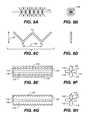
- FIGS. 8A-Bshow side and front views, respectively, of a support having an open network structure.
- FIGS. 8C-Dshow side and front views, respectively, of a support having a longitudinal zig-zag configuration that will contact the wall of Schlemm's canal at at least three points (labeled P 1 , P 2 , P 3 ).
- FIGS. 8E-Fshow side and front views, respectively, of a support having a rod-like member with continuously fluted edges and fenestrations.
- FIGS. 8G-Hshow side and front views, respectively, of another variation of a support having a rod-like member with continuously fluted edges.
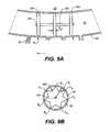
- FIGS. 9A-Bshow expanded cross-sectional views of a support implanted within Schlemm's canal.
- FIGS. 10A-Cillustrate various configurations of supports implanted into Schlemm's canal.
- FIGS. 11A-B and Dillustrate configurations of supports having a smaller radius of curvature then Schlemm's canal.
- FIG. 11Cshows a support having a larger radius of curvature than Schlemm's canal.
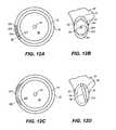
- FIG. 12Aillustrates a variation of a support traversing the center of the central core of Schlemm's canal.
- FIG. 12Bshows a cross-sectional view along line
- FIG. 12Cillustrates a variation of a support traversing the central core of the canal.
- FIG. 12Dshows a cross-sectional view along line
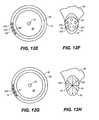
- FIG. 12Eillustrates a variation of a support that occupies the majority of the central core of the canal.
- FIG. 12Fshows a cross-sectional view along line IV-IV′.
- FIG. 12Gillustrates a variation of support having an open network that occupies a portion of the central core of the canal.
- FIG. 12Hshows a cross-sectional view along line V-V′.
- FIG. 13shows an illustrative example of a support that can be modified using electromagnetic radiation.
- FIG. 14Aillustrates a syringe that can be used to insert a support into Schlemm's canal.
- FIG. 14Billustrates a variation in which a support is threaded onto a guide element for insertion and positioning in Schlemm's canal.
- FIG. 14Cillustrates a cross-sectional view of a support having a central bore to accommodate a guide element.
- FIG. 14Dillustrates a variation in which a syringe and a guide element are used for insertion and positioning of a support in Schlemm's canal.
- Described hereare devices, kits and methods to reduce intraocular pressure by maintaining or restoring Schlemm's canal so that at least a portion of the canal is patent or unobstructed.
- the devices, kits and methodsoperate to keep Schlemm's canal from collapsing while not substantially interfering with the eye's natural drainage mechanism for aqueous humor, in which transmural fluid flow across Schlemm's canal occurs.
- the devicesare implantable in Schlemm's canal with minimal trauma to the eye.
- FIG. 1shows a partial cross-sectional view of the anatomy of a normal human eye.
- Ciliary body 12is connected to iris 18 and to lens 16 via zonular fibrils 14 .
- the anterior chamber of the eye 20is bounded on its anterior (front) surface by cornea 24 .
- pupil 22In the center of iris 18 is pupil 22 .
- Cornea 24is connected on its periphery to sclera 26 , which is a tough fibrous tissue forming the white shell of the eye.
- Trabecular meshwork 28is located on the outer peripheral surface of anterior chamber 20 .
- the trabecular meshworkextends 360° circumferentially around the anterior chamber.
- Schlemm's canal 30Located on the outer peripheral surface of meshwork 28 is Schlemm's canal 30 .
- Schlemm's canalextends 360° circumferentially around the trabecular meshwork.
- meshwork 28 and sclera 26is angle 32 .
- Conjunctiva 34is a membrane overlaying sclera 26 and lining the inside of the eyelid (not shown).
- FIG. 2shows a partial cross-sectional view of flow of aqueous humor within and out of a normally functioning human eye.
- Aqueous humoris produced in ciliary body 12 and its path through and out of the eye is indicated by solid directional line 36 .
- the aqueous humorflows from ciliary body 12 , between lens 16 and iris 18 , through pupil 22 into anterior chamber 20 , across trabecular meshwork 28 , across Schlemm's canal 30 , into aqueous veins or collector channels (not shown) and finally into the bloodstream via conjunctival vasculature.
- FIG. 3shows a front view of normal flow of aqueous humor out of the eye.
- Aqueous humorenters anterior chamber 20 via pupil 22 .
- the fluidflows outwardly toward the periphery of the eye, with the general path of flow indicated by solid directional lines 36 .
- the fluidcrosses trabecular meshwork 28 and traverses Schlemm's canal 30 to reach aqueous veins or collector channels 38 .
- collector channels 38There are typically 25-30 collector channels located in a human eye.
- Collector channels 38are connected to vasculature 40 , whereby the drained aqueous humor enters the bloodstream.
- FIGS. 4A-BDifferent fluid flow paths in and across Schlemm's canal are illustrated in FIGS. 4A-B .
- FIG. 4Ashows a front view of an eye
- FIG. 4Bshows an expanded cross-sectional view along line I-I′.
- Circumferential (i.e., longitudinal) flow along and around circular canal 30is depicted by directional lines 50 .
- Fluid that does not traverse canal 30 to reach collector channels 38may not be effectively drained from the eye.
- Examples of fluid flow paths that can effectively drain the eyeare illustrated by directional lines 52 , 52 ′, and 52 ′′. In each of these paths, fluid enters trabecular meshwork 28 along its inner peripheral surface 60 and exits the meshwork along its outer peripheral surface 62 ′.
- Meshwork outer peripheral surface 62 ′provides the inner peripheral surface or wall of Schlemm's canal 30 .
- Transmural fluid flow across Schlemm's canalinvolves two instances of transmural flow across walls or boundaries. First, fluid must flow from trabecular meshwork 38 through inner peripheral surface or wall 62 ′ of Schlemm's canal 30 to reach lumen 64 of the canal. Second, fluid must flow from lumen 64 through canal outer peripheral wall 62 ′′ through apertures 38 ′ to enter collector channels 38 . Finally, the collector channels 38 feed the drained fluid into vasculature.
- Lumen 64 of canal 30includes a central core region 67 .
- Devices to reduce intraocular pressurecomprising a support that can be implanted circumferentially in Schlemm's canal to maintain the patency of at least a portion of the canal are described here.
- the supportoccupies at least a portion of a central core of Schlemm's canal and does not substantially interfere with transmural flow across the canal.
- maintain the patencyof at least a portion the canal, it is meant that the support operates to keep the canal at least partially unobstructed to transmural flow, such that fluid can 1) exit through the trabecular meshwork; 2) traverse the canal; and 3) drain via the collector channels.
- To maintain the patency of the canalit is not necessary that the support leave the canal unobstructed in regard to circumferential flow.
- the supportdoes not significantly block either fluid outflow from the trabecular meshwork or fluid outflow to the collector channels.
- the supportallows between about 0.1 and about 5 microliters per minute aqueous outflux from the eye through the trabecular meshwork and collector channels.
- the “central core of Schlemm's canal”refers to the region around the cross-sectional center of the canal in the interior space of the canal lumen, i.e., not on the periphery of the canal. Therefore, a device that occupies at least a portion of a central core of Schlemm's canal can traverse at least a portion of the canal's lumen.
- devices described hereneed not comprise an open-ended tubular support placed longitudinally along Schlemm's canal, i.e., the devices and supports can be non-tubular.
- a longitudinal, open-ended tubular supportcan enable longitudinal flow along the canal.
- the eyemay not be effectively drained unless the fluid eventually traverses the canal. That is, transmural fluid flow across two boundaries must occur: 1) fluid must flow from the trabecular meshwork through a canal inner wall coincident with an outer peripheral boundary of the trabecular meshwork to reach the canal lumen; and 2) fluid must flow from the canal lumen through apertures in the canal outer peripheral wall to reach the connector channels.
- a tubular support inserted longitudinally into the canalcan have significant surface area overlap with surfaces of the canal such that transmural flow across the canal may be significantly impeded.
- a longitudinal tubular support placed in Schlemm's canalmay block flow into the canal from the trabecular meshwork and block flow out of the canal into the collector channels.
- Devices described herein for treating elevated intraocular pressureinclude a support that is implanted within Schlemm's canal.
- the devicewill reduce the intraocular pressure by 1-40 mm Hg, for example by at least 2 mm Hg.
- the devicewill reduce intraocular pressure by at least 4 mm Hg, or at least 6 mm Hg, or at least 10 or 20 mm Hg.
- the devicewill operate to bring the intraocular pressure into the range of about 8 to about 22 mm Hg.
- the supportcan be configured in a variety of ways to at least partially prop open Schlemm's canal thereby maintaining its patency without substantially interfering with or impeding transmural fluid flow across Schlemm's canal.
- the supportmay interfere with or block longitudinal flow along or around the canal. In many instances, the support will be contained entirely within Schlemm's canal. In some variations the support will be implanted within the canal, but may extend partially beyond Schlemm's canal, e.g., into the trabecular meshwork.
- a support to maintain at least partial patency for Schlemm's canal to enable fluid flow between an inner wall of the canal and an outer wall of the canalcan comprise elements or structures such as bead-like elements or beads, which can be connected together, e.g., as a string of beads. Individual elements or beads or a connected group of elements or beads can be inserted directly into Schlemm's canal.
- FIG. 5Aillustrates a front view of an eye having a narrowed or collapsed Schlemm's canal 30 , where canal outer peripheral wall 62 ′′ is very close to canal inner peripheral wall 62 ′.
- Schlemm's canal 30is depicted in FIG. 5A as being uniformly narrow around the entire circumference of canal, it is possible that only a portion of Schlemm's canal is narrowed or collapsed.
- net efflux of aqueous from the anterior chamber to the collector channels 38is diminished, thereby increasing intraocular pressure. As a result, the risk of pre-glaucoma, ocular hypertension, or glaucoma can increase.
- FIG. 5Billustrates an example of a device 70 inserted into Schlemm's canal 30 through incision site 74 .
- Device 70 in this exampleis positioned to one side of incision site 74 .
- Device 70includes support 72 that is configured to keep Schlemm's canal at least partially open to transmural fluid flow across both canal inner wall 62 ′ and canal outer wall 62 ′′ to reach collector channels 38 via apertures 38 ′.
- support 72includes elements or beads 76 connected with connectors 78 .
- the distance between canal inner wall 62 ′ and outer wall 62 ′′is approximately determined by the cross-sectional dimension of support 72 , which is in turn determined by the largest cross-sectional diameter of the beads 76 .
- circumferential (i.e., longitudinal) fluid flow around and along the canal 30 indicated by directional line 50may be inhibited by the insertion of support 72 into the canal.
- transmural flow across both walls or boundaries of the canal indicated by directional lines 52 , 52 ′, 52 ′′is enhanced by support 72 and fluid is able to reach collector channels 38 and be drained from the eye.
- support 72can effectively reduce intraocular pressure by utilizing the eye's natural drainage mechanism.
- Incision 74need only be large enough to accommodate the diameter of beads 76 , so that trauma to the eye is minimized.
- Beadscan have cross-sectional dimensions in the range from about 50 microns to about 500 microns.
- relatively small cross-sectional diameterse.g., about 50 microns
- Insertion of beads having relatively large cross-sectional diameterse.g., greater than about 300 microns
- stretch the trabecular meshworkmay further enhance drainage.
- FIG. 5Cillustrates an alternate configuration of a device 80 inserted into Schlemm's canal 30 through incision site 84 .
- Device 80includes support 82 that extends to both sides of incision site 84 .
- Support 82includes elements or beads 76 connected with connectors 88 and 88 ′.
- connector 88 ′is of a different length than connectors 88 .
- beads 76may impede circumferential (i.e., longitudinal) fluid flow around and along canal 30 indicated by directional line 50 .
- transmural flow across the canalis enhanced by support 82 that maintains patency across the canal and allows fluid to reach collector channels 38 . If the beads are fenestrated or comprise rough, spiked, or fluted perimeters, then circumferential fluid flow through or around the beads may also occur.
- Elements or beads used in a supportmay be hollow and closed structures, open structures, solid structures, porous structures, or any combination thereof, and may be of any suitable shape.
- FIGS. 6A and 6Billustrate side and front views, respectively, of exemplary elements or beads that may be used in the supports described here.
- solid 90 or hollow 91spherical 90 , spheroid 92 , ovoid 93 , conical 94 , disk-shaped 95 , polyhedral 96 , rod-like 97 , or beads with fluted edges 98 , rough edges, 89 , or spiked edges 88 may be used. In some instances, it may be desired to round corners or edges of the beads. As illustrated in FIG.
- elements or beads 76may include fenestrations 99 , 99 ′.
- Fenestrationsmay have any suitable cross-sectional shape, such as round or quadrilateral. Although a disc-shaped bead 76 is shown in FIG. 6C , any shape of bead can be fenestrated.
- two or more beads 76 in a supportmay be adjacent to each other. Adjacent beads may be juxtaposed ( FIG. 7A ), connected and juxtaposed ( FIGS. 7B and 7C ), or connected together with connectors 100 , 100 ′ to form intervals between beads ( FIG. 7D ). In addition, beads may be threaded onto a connector 101 ( FIG. 7E ). Multiple beads used in a single support may have the same or different shapes, and may be made of the same or different materials.
- Junctions 102 between beads as shown in FIG. 7Bcan be made using any suitable technique, such as by using an adhesive, chemical bonding, mechanical interlocking, or welding. Beads may also be juxtaposed and connected as shown in FIG. 7C by threading onto a guide element 104 .
- Guide element 104can comprise a fiber, a suture, a guide wire, a fixture, or the like.
- the beadscan be fixed in a juxtaposed configuration on a guide element, e.g., by knotting ends of the fiber or by providing other end-blocking devices 106 , such as clips, caps, protrusions, or the like on ends 108 of element 104 .
- any or all of the beadscan be attached to guide element 104 , e.g., beads occupying end positions may be attached to element 104 and function as blocking beads to keep beads from sliding off ends 108 of element 104 . Alternatively, beads may slide along element 104 .
- Guide element 104can be flexible, such as thin polymer threads, such as a suture, or metal wires. Alternatively, element 104 can be flexible but fixable, such as one or more shapeable metal wires that can be bent into a desired position and maintain that position against some amount of external stress or pressure. In other variations, guide element 104 can be rigid, e.g., a molded polymeric piece or a stiff metal piece.
- multiple connectors 100 , 100 ′may be used in a single support, with at least one connector inserted between adjacent beads 76 . If multiple connectors are used, they may be of the same or different lengths. In addition, multiple connectors within the same support may be made of the same or different materials, and the connectors may be made of the same or different materials than the beads. Discrete connectors 100 , 100 ′ can be inserted between beads 76 and attached to adjacent beads using any suitable method including using adhesives, chemical bonding, welding, mechanical interlocking, knots, or any combination thereof. In some variations, connectors 100 , 100 ′ between beads can be configured to function as spacers between individual beads. As illustrated in FIG.
- beads 76can also be threaded onto a connector 101 . If the beads are threaded onto a connector, the beads can be maintained in fixed positions along the connector 101 by any suitable method, including using adhesives, chemical bonding, welding, clips, protrusions on the connector, mechanical interlocking locking between a connector and a bead, knots, or any combination thereof. Alternatively, some or all beads may slide along connector 101 .
- Connectors 100 , 100 ′, 101can be flexible, such as thin polymer threads or metal wires. Connectors 100 , 100 ′, 101 can also be flexible but fixable, such as shapeable metal wires. Alternatively, connectors 100 , 100 ′, 101 may be rigid, such as molded polymeric connectors or stiff metal connectors.
- a supportcan be a unitary structure of fixed or variable length.
- Supportscan be solid, hollow, or porous, or any combination thereof.
- a supportcan be partially solid and partially hollow. Examples of support configurations are shown in side view and front view in FIGS. 8A-F .
- a supportcan have an open network structure.
- Such a supportcan be fabricated out of shapeable metal wires, for example.
- the support illustrated in FIGS. 8A-Bwill have minimal surface area contact with the walls of Schlemm's canal, i.e., only point contacts at the end of wires or fibers 170 .
- a support having an open network structurecan be at least partially made from a mesh or foam.
- the mesh or foamcan be made of any suitable material, e.g., metal or plastic.
- the supportcan have a sinusoidal or zig-zag configuration extending along a selected length of Schlemm's canal.
- the supportwill contact the wall of Schlemm's canal at at least three points, labeled P 1 , P 2 , and P 3 , after implantation.
- FIGS. 8E-Hexamples of rod-like supports having fluted edges are shown.
- fluted edges 110extend longitudinally along sides 112 between ends 114 of the support to form structures 116 .
- Structures 116can include fenestrations 113 .
- the supportcan include central bore 117 .
- fluted edges 110 ′extend along sides 112 ′ to form structures 116 ′.
- Structures 116 ′have serrated outer surfaces 115 ′ extending between ends 114 ′.
- the supportcan include central bore 117 ′.
- the supportmay contact the canal walls at at least four points. In some variations, the support is adjustable.
- a common characteristic of the support configurations described hereis that they need not have continuous or extensive contact with a wall of Schlemm's canal. Indeed, many of the described devices and structures have minimal tangential, periodic, or sporadic contact with the wall.
- the surface of the supportcan be rough, smooth, spiked or fluted. As the example shown in FIGS. 8A-B shows, some supports only have point contacts with the canal wall. For the supports shown in FIGS. 5B-C , the rounded beads of each of the supports make only tangential contact with the canal wall. Bead shapes can be selected or designed to have minimal surface area contact with canal walls, e.g., beads 98 having fluted edges as shown in FIGS. 6A-B may have low surface area contact with canal walls.
- supports having widely spaced apart beadse.g., by connectors illustrated in FIGS. 7D-E that can function to space beads at desired intervals to reduce contact with canal walls yet operate to keep the canal open.
- the supportcontacts the interior wall of the canal at at least two points; or at at least three points.
- FIGS. 9A-BExpanded cross-sectional views of a support 152 implanted circumferentially in Schlemm's canal are provided FIGS. 9A-B .
- the fraction of canal wall surface area in contact with a supportcan be estimated by viewing the inside of Schlemm's canal as a slightly arcuate cylinder C having length L, extending circumferentially from a first end X 1 to a second end X 2 of support 152 , and inside radius R i .
- the supportcontacts less than 0.1% or less than 1% of the surface area of the cylinder C as described above.
- the supportcontacts less than 10% of the surface area of C.
- the supportcontacts less than 30% of the surface area of C.
- 9A-Bcontacts the canal wall 62 only at bead outer peripheral edges at E 1 -E 7 , along a distance of the bead width B W . There is no contact with the canal walls where connectors 156 space apart beads 154 , and no contact in fluted regions 160 of beads 154 .
- the design feature of minimal support contact with canal wallsallows a support to maintain patency of the canal without substantially interfering with transmural flow across the canal. If a substantial portion of the surface area of the inner periphery of the canal adjacent to the trabecular network or of the surface area of the outer periphery of the canal where the collector channels are located is blocked, effective fluid flow across the canal may be impaired.
- Supportscan have variable lengths and thicknesses.
- the length of supports using beadscan be tuned by varying the number, type, or spacing of beads, or any combination thereof.
- the thickness of a supportcan be increased by adding one or more beads having larger dimensions.
- Unitary supportscan also be built with varying lengths, or with adjustable (e.g., trimmable) dimensions.
- a cross-sectional dimension 117 of the supportcan be decreased or increased by apply tension along dimension 119 .
- a support 160can extend essentially around the entire circumference of Schlemm's canal 30 .
- a supportcan extend approximately half way around the circumference of the canal (not shown).
- a support 162can extend less than half way around the canal.
- a support 164can extend a quarter or less of the circumference around the canal.
- more than one support 164 , 166 , 168can be inserted into a single Schlemm's canal. If multiple supports are inserted into a single canal, they can be of different shapes, lengths, materials or sizes.
- a supportcan be configured such that it will open the canal beyond a maximum cross-sectional dimension of the support itself.
- device 130comprising support 132 is inserted into Schlemm's canal 30 .
- Support 132comprises beads 134 which have a maximum cross-sectional dimension B D .
- Support 132comprises a stiff arcuate element 135 with a radius of curvature R supp smaller than the radius of curvature of Schlemm's canal R SC .
- the smaller, fixed radius of curvature R supp of arcuate member 135urges canal 30 to open more than B D .
- support 179comprises an arcuate member 180 without beads having a radius of curvature R supp that is less than the radius of curvature R SC of the canal. Member 180 is sufficiently stiff to urge the canal open.
- support 181comprises an arcuate member 182 having a radius of curvature R supp larger than that of Schlemm's canal R SC . Member 182 is also sufficiently stiff to urge the canal open.
- Arcuate members 135 , 180 and 182can comprise a shape memory material such as Nitinol, for example.
- support 181can include beads 184 .
- the radius of curvature R supp of an arcuate memberscan be about 10%, 20%, 30%, 40%, or 50% or smaller or larger than that of Schlemm's canal R SC .
- an arcuate membercan have a radius of curvature of about 3 mm to about 8 mm.
- the radius of curvature of an arcuate member R supp in a supportis about 3 mm, or about 4 mm, or about 5 mm.
- the radius of curvature R supp of an arcuate member in a supportis about 6 mm, or about 7 mm, or about 8 mm.
- the supports described hereoccupy at least a portion of a central core of Schlemm's canal.
- the central core of Schlemm's canalis the region around the cross-sectional center of the canal in the interior space of the canal lumen.
- a support that occupies at least a portion of the central core of the canalcan traverse at least a portion of the canal lumen.
- some variations of supportscan traverse the cross-sectional center of the canal at at least one point.
- FIG. 12Aa front view of a support 220 having beads 222 connected with connectors 224 is provided.
- FIG. 12Bshows an expanded cross-sectional view along line II-II′. Support 220 occupies a portion canal central core 67 in canal lumen 64 .
- Trabecular meshwork 28is shown adjacent to canal 30 .
- support 220traverses the cross-sectional center 66 of the canal.
- supportscan traverse the lumen of the canal off-center, e.g., appearing as a chord across the canal lumen in cross-section.
- FIG. 12Ca front view of an arcuate support 210 is shown.
- FIG. 12Dshows an expanded cross-sectional view along line III-III′.
- Support 210traverses and occupies a portion of central core 67 in lumen 64 of canal 30 without passing through canal center 66 .
- the supportcan occupy the majority of the central core of the canal. Referring to FIG.
- FIG. 12Ea front view of support 230 comprising disc-like beads 232 is shown.
- a cross-sectional view along line IV-IV′is shown in FIG. 12F .
- bead 232 with fenestrations 234occupies the majority of central core 67 of canal 30 .
- the supportoccupies only a small portion of the central core of the canal.
- FIG. 12Ga front view of a support 240 having an open network structure is shown.
- a cross-sectional view along line V-V′is shown in FIG. 12H .
- a supportcan made of a variety of different materials.
- the supportshould comprise a biocompatible material, such as a biocompatible polymer, ceramic or ceramic composite, glass or glass composite, metal, or combinations of these materials.
- biocompatible metalsinclude stainless steel, gold, silver, titanium, tantalum, platinum and alloys thereof, cobalt and chromium alloys, and titanium nickel alloys such as Nitinol.
- biocompatible polymersinclude high density polyethylene, polyurethane, polycarbonate, polypropylene, polymethylmethacrylate, polybutylmethacryate, polyesters, polytetrafluoroethylene, silicone, polyvinyl alcohol, polyvinyl pyrrolidone, polyvinyl chloride, ethyl vinyl acetate, collagen, collagen derivatives, flexible fused silica, polyolefins, NYLON® polymer, polyimide, polyacrylamide, fluorinated elastomers, and copolymers and blends thereof.
- biocompatible hydrogelscan be used in supports and devices described herein. As discussed in more detail below, biocompatible polymers may be biodegradable.
- a supportcan be made of a single material or a combination of materials. In some variations, a support made from a first material is coated with a second material, e.g., to enhance or improve its biocompatibility.
- the biocompatible polymer in a supportwill include a biodegradable polymer.
- suitable biodegradable polymersinclude collagen, a collagen derivative, a poly(lactide), a poly(glycolide), a poly(lactide-co-glycolide), a poly(lactic acid), a poly(glycolic acid), a poly(lactic acid-co-glycolic acid), a poly(lactide)/poly(ethylene glycol) copolymer, a poly(glycolide)/poly(ethylene glycol) copolymer, a poly(lactide-co-glycolide)/polyethylene glycol) copolymer, a poly(lactic acid)/poly(ethylene glycol) copolymer, a poly(glycolic acid)/poly(ethylene glycol) copolymer, a poly(lactic acid-co-glycolic acid)/poly(ethylene glycol) copolymer, a poly(caprolactone),
- At least a portion of the supportcan be made from a shape memory material.
- shape memory alloyse.g. a nickel-titanium alloy can be used.
- shape memory polymerse.g., polymers made from copolymerizing monomers oligo(e-caprolactone) dimethacrylate and n-butyl acrylate or polymers based on styrene acrylate, cyanate ester and epoxies, can be used. If a shape memory material is used in the support, the support can have a compressed state prior to and during implantation, and an expanded state following implantation.
- a compressed state supportcomprising a shape memory material can allow for a smaller incision and facilitate insertion into a narrowed or compressed Schlemm's canal.
- the supportcan be expanding using any suitable method, e.g., thermally activated by body heat or an alternate heat source, to adopt an expanded state, thereby opening the canal.
- the supportcan include an active agent, such as a pharmaceutical.
- Active agentscan include prostaglandins, prostaglandin analogs, beta blockers, alpha-2 agonists, calcium channel blockers, carbonic anhydrase inhibitors, growth factors, such as tissue growth factors and vascular endothelial growth factors, anti-metabolites, chemotherapeutic agents such as mitomycin-C,5-fluorouracil, steroids, antagonists of growth factors such as antagonists of vascular endothelial growth factors, or combinations thereof.
- the active agentcan be provided as a coating on at least a portion of a support.
- the active agentcan be delivered throughout the eye by dissolution or other dispersal mechanisms.
- at least a portion of the supportcan be impregnated with the active agent.
- the active agentcan be dispersed within at least a portion of the support. For example, a cavity in the support can be filled with the active agent.
- the delivery of the active agentcan be controlled by time-release.
- the portion of the support containing the active agentcan include a time release coating or time release formulation designed to gradually dissipate the active agent over a certain period of time.
- Biodegradable coatings and formulations for time-release of active agentsare known in the art.
- the supportcan comprise multiple layers, where the layers each comprise an active agent.
- support layerscan be used to release a series of different agents, or a series of doses of the same agent.
- Such layerscan be part of a coating applied to a support, or part of a support body.
- the supportcan comprise biodegradable layers containing no active agent that can be applied or interspersed between other layers to further control delivery of active agents to the eye.
- a supportcan be fenestrated, perforated, bent, shaped or formed using a laser to enhance intraocular pressure reduction.
- predetermined localized portions 120 of support 122can be designed to absorb light of a certain wavelength or wavelength range. Preferential absorption can be achieved by material selection and/or by doping with chromophores. Upon irradiation with sufficient energy at the selected wavelength or wavelength range, the patterned regions 120 will ablate or melt, leaving new or enlarged perforations or indentations in the support.
- a pulsed titanium sapphire laser operating between about 750 and about 800 nmcan be used to ablate gold regions. If beads 126 in support 120 are hollow, then after irradiation and ablation, features 120 will become fenestrations. The fenestrations can be created to make support 122 more porous in nature or to allow release of an active agent from within a support, e.g., from within beads 126 .
- a maskin combination with electromagnetic radiation to alter a support, such as by patterning or machining. The modification of a support using electromagnetic radiation can be carried out prior to or subsequent to insertion.
- the visual appearance of the supportcan be enhanced under certain conditions to facilitate placement or to monitor the position or condition of the support.
- Visual enhancementcan be achieved by incorporating into or onto the support chromophores that fluoresce or phosphoresce upon excitation with a light source. Chromophores can also assist a clinician in verifying the position of the support postoperatively using a gonioscope, for example.
- Light sourcescan include lasers, lamps, and light emitting diodes.
- transmission or absorption filtersmay be used to select the wavelength of the excitation source or to detect or view emission. Emission from a support capable of visual enhancement may be in the wavelength range of about 300 nm to about 800 nm.
- the chromophorescan be an integral component of the material making up the support, doped into support material, or coated or sprayed onto the support. Visually-enhancing chromophores can be applied on a temporary basis, or on a permanent basis.
- An example of a suitable chromophoreis fluorescein, which can be excited with any laser or lamp emitting at about 400 to about 500 nm.
- phosphorus-based chemiluminescent or photoluminscent pigmentscan be used, which can be selected to absorb at various wavelengths across the visible spectrum.
- the supportmay be capable of being attached to tissue.
- the supportmay include a hook, loop, clip, extension, or the like that may be easily attached to tissue.
- the supportmay also be attached to tissue using sutures or adhesives.
- the supportmay be attached to tissue using more than one attachment method, e.g., suturing may be used in combination with a loop, or an adhesive may be used in combination with a hook.
- the supportmay be allowed to self-position in Schlemm's canal.
- the supportmay be mobile within Schlemm's canal.
- Kits for reducing intraocular pressurecontain at least one support that can be implanted circumferentially within Schlemm's canal configured to maintain the patency of at least a portion of Schlemm's canal.
- the supportoccupies at least a portion of a central core of Schlemm's canal and does not substantially interfere with transmural flow across the canal.
- the kitsalso provide an introducer or delivery device for implanting the support in the canal.
- the support and introducerare provided in packaged combination in the kits.
- the kitscan also include instructions for use, e.g., for implanting and inspecting the support.
- the introducercan be inserted into the eye and is capable of implanting the support at the desired implantation position within Schlemm's canal.
- an introducermay include a tubular cannula through which the support may be passed.
- the introducermay include a tubular or solid pusher rod that can be used to push or advance the support into and/or around Schlemm's canal.
- a pusher rod or plungercan be used without a cannula to introduce a support into the canal.
- a supportcan be installed into the lumen of a cannula prior to insertion, the distal end of the cannula positioned at or near the desired support location, and the pusher rod operated from the proximal end to push the support distally out of the distal end of the cannula and into the canal.
- the cannula and/or the pusher rodmay be flexible and small enough in diameter to extend at least partially around the canal.
- a proximal end of a suturecan be introduced into the canal via a cannula and the suture extended circumferentially around the canal. A distal portion of the suture can be connected to the support and force applied to the proximal end of the suture to pull the support into the canal.
- the supportcan then be positioned within the canal by pulling the suture in a distal or proximal direction.
- the suturecan be used to anchor the support within the canal.
- the supportcan be directly introduced into the canal using surgical forceps, or the like.
- FIGS. 14A-Dillustrate additional variations for introducing a support into the canal.
- a support 200can be introduced into the canal using syringe 202 and plunger 204 .
- Syringe 202has distal end 206 that can be at least partially inserted into or placed adjacent to an opening in the canal. Force in a distal direction is applied to plunger 204 , thereby pushing support 200 into the canal.
- distal end 208 of guide element 210can be at least partially introduced into the canal.
- Guide element 210can be a guide wire.
- Guide element 210can be extended circumferentially along the canal to aid in positioning the support.
- Support 212comprises central bore 218 capable of accommodating guide element 210 such that support 212 can be threaded onto guide element 210 and slidably positioned along the guide element. Once distal end 209 of support 212 is threaded onto guide element 210 , support 212 can be pushed in a distal direction along guide element 210 to insert support 212 into the canal. In some variations, support 212 can remain threaded onto guide element 210 , and guide element 210 can remain in the canal. In other variations, support 212 can be slid off distal end 208 of guide element 210 , and the guide element can be pulled in a proximal direction for removal. Referring to FIGS.
- syringe 202 with plunger 204can be used in combination with a guide element 210 .
- distal end 208 of guide element 210is inserted at least partially into Schlemm's canal.
- Guide element 210can be extended circumferentially along the canal to aid in positioning the support.
- Support 212has central bore 218 capable of accommodating guide element 210 .
- Proximal end 211 of guide element 210is inserted into bore 218 .
- Plunger 204is depressed in a distal direction to push support 212 into the canal and slide support 212 along element 210 .
- Guide element 210can remain in the canal or be removed following insertion of the support.
- Supports 200 , 212must be sufficiently resilient to withstand force encountered as they are pushed into the canal.
- a positioning devicemay be used with the introducer to position or adjust the support within the canal.
- a positioning devicecan include a rod, grippers, a clamp, a hook, or the like.
- a device or system capable of dilating the canal to facilitate insertion of a supportmay be included in the kits, e.g., a syringe or other device capable of injecting fluid into the canal.
- kitscontain at least two supports. Multiple supports can be implanted within one eye or within multiple eyes. If the kits contain multiple supports, the kits may also contain multiple introducers. Alternatively, the same introducer may be used for implantation of multiple supports, especially if the multiple supports are being delivered to a single eye. If multiple supports are to be delivered with the same introducer, then the multiple supports can be preloaded into the introducer for sterility. If more than one support is included in a kit, the supports may be of different shapes, sizes, lengths, or materials. If the kits contain more than one support to be implanted into a single eye, the supports can be connected together.
- kitscan comprise an active agent, such as a pharmaceutical agent.
- the active agentmay be included as an integral part of the support, or may be supplied in kits for application to the support or to the eye during or after implantation.
- active agentsthat may be supplied as part of the kits include prostaglandins, prostaglandin analogs, beta blockers, alpha-2 agonists, calcium channel blockers, carbonic anhydrase inhibitors, growth factors, such as tissue growth factors or vascular endothelial growth factors, anti-metabolites, chemotherapeutic agents such as mitomycin-C,5-fluorouracil, steroids, antagonists of growth factors, such as antagonists of vascular endothelial growth factor, and combinations thereof.
- kitsmay contain a fixation device for attaching a support to tissue.
- a fixation devicecan include sutures, hooks, barbs, clips, adhesives, and combinations thereof.
- the kitsmay include a system for visually enhancing the support to facilitate viewing, positioning, and monitoring of a support.
- a system for visually enhancing the supportcan include a light source, a transmission or absorption filter, a mirror, a composition comprising a chromophore capable of fluorescing or phosphorescing that can be applied to the support, or any combination thereof. Chromophores can assist a clinician in verifying the position of the support postoperatively using a gonioscope, for example.
- the light sourceis capable of exciting a chromophore contained within or on the support such that the chromophore emits fluorescence or phosphorescence.
- the emissionis preferably within the wavelength range of about 300 nm to about 800 nm.
- a suitable light source for such a systemcan comprise a laser, a light emitting diode, or a lamp.
- transmission or absorption filtersmay be used to further select the wavelength range of the excitation source or view or detect emission from chromophores.
- One or more mirrorsmay be used to direct a light source or emitted light, or to view the support.
- the methodscomprise inserting a support circumferentially within Schlemm's canal, such that the support maintains the patency of at least a portion of the canal.
- the supportoccupies at least a portion of a central core of Schlemm's canal and does not substantially interfere with transmural flow across Schlemm's canal.
- the methodscan comprise inserting a support circumferentially into Schlemm's canal using an introducer and/or a positioning device.
- the introducercan include a cannula and a tubular or hollow pusher rod.
- the supportcan be installed in the lumen of the cannula at its distal end and the pusher rod can be inserted into the lumen of the cannula at its proximal end and extended distally to push the support into position in the canal.
- the cannula and/or the pusher rodmay be flexible and small enough in diameter to at least partially extend circumferentially around the canal.
- a positioning devicecan be used in addition to an introducer.
- the positioning devicecan comprise a second rod, a gripper, a hook, a clamp, or the like.
- the methodsinclude illuminating a support with a light source to causes the support to fluoresce or phosphoresce, thus aiding the visual appearance of the support.
- the illuminating of the supportcan occur during or after implantation to inspect the support, e.g., to monitor its position, condition, or performance.
- the methodswill also comprise dilating Schlemm's canal prior to insertion of the support.
- Dilation of the canalcan be accomplished by injecting fluid into the canal.
- a high viscosity fluidsuch as sodium hyaluronate, or other dilating fluids known in the art, can be used to dilate the canal.
- the methodsmay include implanting more than one support into an eye.
- the methodswill include implantation of two or more supports circumferentially adjacent to each other within the canal, and in other variations, the methods will include implantation of supports circumferentially opposed to each other within the canal, e.g., two supports centered about 180° apart around the circumference of Schlemm's canal.
- Some variations of the methodscan comprise connecting together multiple supports in a single eye.
- the methodscan include anchoring the support to tissue surrounding Schlemm's canal. Anchoring the support to tissue can be accomplished in a variety of ways, e.g., by suturing, application of adhesives, installation of hooks, clips, or the like, or combinations thereof.
- the methodscan comprise selecting the size of the support such that the support fits securely into the canal by a friction fit. Examples of arcuate supports that can be implanted with a friction fit are illustrated in FIGS. 11A-C .
- a supportcan include regions capable of preferentially absorbing a certain wavelength range.
- electromagnetic radiation of the appropriate wavelength range with sufficient energyis incident upon the support, material in the preferentially absorbing regions will melt or ablate, resulting in perforations or indentations in the support at those regions.
- a pulsed titanium sapphire laser emitting at about 750 nm to about 800 nm incident on goldcan cause the gold to melt or ablate.
- the alteration of the support using electromagnetic radiationcan occur before or after implantation of a support. For example, fenestrations can be created or enlarged in a support after the support has remained in an eye for a period of time to enhance drainage.
Landscapes
- Health & Medical Sciences (AREA)
- Ophthalmology & Optometry (AREA)
- Engineering & Computer Science (AREA)
- Biomedical Technology (AREA)
- Heart & Thoracic Surgery (AREA)
- Vascular Medicine (AREA)
- Life Sciences & Earth Sciences (AREA)
- Animal Behavior & Ethology (AREA)
- General Health & Medical Sciences (AREA)
- Public Health (AREA)
- Veterinary Medicine (AREA)
- Nuclear Medicine, Radiotherapy & Molecular Imaging (AREA)
- Surgery (AREA)
- Prostheses (AREA)
- Materials For Medical Uses (AREA)
Abstract
Description
Claims (71)
Priority Applications (4)
| Application Number | Priority Date | Filing Date | Title |
|---|---|---|---|
| US13/025,112US9370443B2 (en) | 2006-06-26 | 2011-02-10 | Intraocular implants and methods and kits therefor |
| US15/182,165US10314742B2 (en) | 2006-06-26 | 2016-06-14 | Intraocular implants and methods and kits therefor |
| US16/413,466US11389328B2 (en) | 2006-06-26 | 2019-05-15 | Intraocular implants and methods and kits therefor |
| US17/866,429US20220354695A1 (en) | 2006-06-26 | 2022-07-15 | Intraocular implants and methods and kits therefor |
Applications Claiming Priority (2)
| Application Number | Priority Date | Filing Date | Title |
|---|---|---|---|
| US11/475,523US7909789B2 (en) | 2006-06-26 | 2006-06-26 | Intraocular implants and methods and kits therefor |
| US13/025,112US9370443B2 (en) | 2006-06-26 | 2011-02-10 | Intraocular implants and methods and kits therefor |
Related Parent Applications (1)
| Application Number | Title | Priority Date | Filing Date |
|---|---|---|---|
| US11/475,523DivisionUS7909789B2 (en) | 2006-06-26 | 2006-06-26 | Intraocular implants and methods and kits therefor |
Related Child Applications (1)
| Application Number | Title | Priority Date | Filing Date |
|---|---|---|---|
| US15/182,165ContinuationUS10314742B2 (en) | 2006-06-26 | 2016-06-14 | Intraocular implants and methods and kits therefor |
Publications (2)
| Publication Number | Publication Date |
|---|---|
| US20110130831A1 US20110130831A1 (en) | 2011-06-02 |
| US9370443B2true US9370443B2 (en) | 2016-06-21 |
Family
ID=38657201
Family Applications (10)
| Application Number | Title | Priority Date | Filing Date |
|---|---|---|---|
| US11/475,523Active2029-10-05US7909789B2 (en) | 2006-06-26 | 2006-06-26 | Intraocular implants and methods and kits therefor |
| US12/695,053Active2027-04-27US8287482B2 (en) | 2006-06-26 | 2010-01-27 | Intraocular implants and methods and kits therefor |
| US13/025,112Active2028-11-10US9370443B2 (en) | 2006-06-26 | 2011-02-10 | Intraocular implants and methods and kits therefor |
| US13/445,816Active2028-01-24US9486361B2 (en) | 2006-06-26 | 2012-04-12 | Intraocular implants and methods and kits therefor |
| US15/182,165Active2027-05-21US10314742B2 (en) | 2006-06-26 | 2016-06-14 | Intraocular implants and methods and kits therefor |
| US15/340,911Active2027-01-01US10398597B2 (en) | 2006-06-26 | 2016-11-01 | Intraocular implants and methods and kits therefor |
| US16/413,466Active2028-04-12US11389328B2 (en) | 2006-06-26 | 2019-05-15 | Intraocular implants and methods and kits therefor |
| US16/526,832Active2028-10-23US11865041B2 (en) | 2006-06-26 | 2019-07-30 | Intraocular implants and methods and kits therefor |
| US17/866,429PendingUS20220354695A1 (en) | 2006-06-26 | 2022-07-15 | Intraocular implants and methods and kits therefor |
| US18/522,058PendingUS20240350314A1 (en) | 2006-06-26 | 2023-11-28 | Intraocular implants and methods and kits therefor |
Family Applications Before (2)
| Application Number | Title | Priority Date | Filing Date |
|---|---|---|---|
| US11/475,523Active2029-10-05US7909789B2 (en) | 2006-06-26 | 2006-06-26 | Intraocular implants and methods and kits therefor |
| US12/695,053Active2027-04-27US8287482B2 (en) | 2006-06-26 | 2010-01-27 | Intraocular implants and methods and kits therefor |
Family Applications After (7)
| Application Number | Title | Priority Date | Filing Date |
|---|---|---|---|
| US13/445,816Active2028-01-24US9486361B2 (en) | 2006-06-26 | 2012-04-12 | Intraocular implants and methods and kits therefor |
| US15/182,165Active2027-05-21US10314742B2 (en) | 2006-06-26 | 2016-06-14 | Intraocular implants and methods and kits therefor |
| US15/340,911Active2027-01-01US10398597B2 (en) | 2006-06-26 | 2016-11-01 | Intraocular implants and methods and kits therefor |
| US16/413,466Active2028-04-12US11389328B2 (en) | 2006-06-26 | 2019-05-15 | Intraocular implants and methods and kits therefor |
| US16/526,832Active2028-10-23US11865041B2 (en) | 2006-06-26 | 2019-07-30 | Intraocular implants and methods and kits therefor |
| US17/866,429PendingUS20220354695A1 (en) | 2006-06-26 | 2022-07-15 | Intraocular implants and methods and kits therefor |
| US18/522,058PendingUS20240350314A1 (en) | 2006-06-26 | 2023-11-28 | Intraocular implants and methods and kits therefor |
Country Status (5)
| Country | Link |
|---|---|
| US (10) | US7909789B2 (en) |
| EP (2) | EP2338445A1 (en) |
| JP (3) | JP5520600B2 (en) |
| ES (1) | ES2391307T3 (en) |
| WO (1) | WO2008002377A1 (en) |
Cited By (6)
| Publication number | Priority date | Publication date | Assignee | Title |
|---|---|---|---|---|
| US20160287440A1 (en)* | 2006-06-26 | 2016-10-06 | Sight Sciences, Inc. | Intraocular implants and methods and kits therefor |
| US9855167B2 (en) | 2012-03-20 | 2018-01-02 | Sight Sciences, Inc. | Ocular delivery systems and methods |
| US10299958B2 (en) | 2015-03-31 | 2019-05-28 | Sight Sciences, Inc. | Ocular delivery systems and methods |
| US10406030B2 (en) | 2010-02-05 | 2019-09-10 | Sight Sciences, Inc. | Intraocular implants and related kits and methods |
| US11504270B1 (en) | 2019-09-27 | 2022-11-22 | Sight Sciences, Inc. | Ocular delivery systems and methods |
| US11877954B2 (en) | 2022-03-16 | 2024-01-23 | Sight Sciences, Inc. | Devices and methods for intraocular tissue manipulation |
Families Citing this family (86)
| Publication number | Priority date | Publication date | Assignee | Title |
|---|---|---|---|---|
| KR20020035476A (en) | 1999-04-26 | 2002-05-11 | 지엠피 비젼 솔루션즈 인코포레이티드 | Shunt device and method for treating glaucoma |
| US6638239B1 (en) | 2000-04-14 | 2003-10-28 | Glaukos Corporation | Apparatus and method for treating glaucoma |
| US7867186B2 (en) | 2002-04-08 | 2011-01-11 | Glaukos Corporation | Devices and methods for treatment of ocular disorders |
| US7431710B2 (en) | 2002-04-08 | 2008-10-07 | Glaukos Corporation | Ocular implants with anchors and methods thereof |
| AU2002258754B2 (en) | 2001-04-07 | 2006-08-17 | Glaukos Corporation | Glaucoma stent and methods thereof for glaucoma treatment |
| US7331984B2 (en) | 2001-08-28 | 2008-02-19 | Glaukos Corporation | Glaucoma stent for treating glaucoma and methods of use |
| CN101170966A (en) | 2005-04-01 | 2008-04-30 | 科罗拉多州立大学董事会 | Graft fixation devices and methods |
| US8968396B2 (en) | 2007-07-23 | 2015-03-03 | Powervision, Inc. | Intraocular lens delivery systems and methods of use |
| US8734377B2 (en) | 2007-09-24 | 2014-05-27 | Ivantis, Inc. | Ocular implants with asymmetric flexibility |
| US7740604B2 (en) | 2007-09-24 | 2010-06-22 | Ivantis, Inc. | Ocular implants for placement in schlemm's canal |
| US20090082862A1 (en) | 2007-09-24 | 2009-03-26 | Schieber Andrew T | Ocular Implant Architectures |
| US20170360609A9 (en) | 2007-09-24 | 2017-12-21 | Ivantis, Inc. | Methods and devices for increasing aqueous humor outflow |
| US8425449B2 (en) | 2009-07-09 | 2013-04-23 | Ivantis, Inc. | Ocular implants and methods for delivering ocular implants into the eye |
| US20090099573A1 (en)* | 2007-10-10 | 2009-04-16 | Donald Gonzales | Apparatus and Method for Treating Eustachian Tube Dysfunction |
| US8808222B2 (en) | 2007-11-20 | 2014-08-19 | Ivantis, Inc. | Methods and apparatus for delivering ocular implants into the eye |
| US8512404B2 (en) | 2007-11-20 | 2013-08-20 | Ivantis, Inc. | Ocular implant delivery system and method |
| JP2011513002A (en) | 2008-03-05 | 2011-04-28 | イバンティス インコーポレイテッド | Method and apparatus for treating glaucoma |
| CN102238926B (en) | 2008-12-05 | 2015-09-16 | 伊万提斯公司 | Methods and devices for delivering ocular implants into the eye |
| CH700142A1 (en)* | 2008-12-22 | 2010-06-30 | Grieshaber Ophthalmic Res Foun | Implant for insertion into Schlemm's canal of eye for use during glaucoma surgery, has connecting parts inserted into lumen of canal in circumferential direction together with ring parts and openings and comprising curved surfaces |
| AU2010271274B2 (en) | 2009-07-09 | 2015-05-21 | Alcon Inc. | Single operator device for delivering an ocular implant |
| US8951221B2 (en)* | 2009-08-20 | 2015-02-10 | Grieshaber Ophthalmic Research Foundation | Method and device for the treatment of glaucoma |
| WO2011046949A2 (en)* | 2009-10-12 | 2011-04-21 | The Regents Of The University Of Colorado, A Body Corporate | Implants for reducing intraocular pressure |
| CN102647960A (en)* | 2009-10-23 | 2012-08-22 | 伊万提斯公司 | Ocular implant system and method |
| US8900298B2 (en) | 2010-02-23 | 2014-12-02 | Powervision, Inc. | Fluid for accommodating intraocular lenses |
| US8945224B2 (en)* | 2010-03-18 | 2015-02-03 | Warsaw, Orthopedic, Inc. | Sacro-iliac implant system, method and apparatus |
| US20120022424A1 (en)* | 2010-05-27 | 2012-01-26 | Iscience Interventional Corporation | Device for placing circumferential implant in schlemm's canal |
| US8545430B2 (en) | 2010-06-09 | 2013-10-01 | Transcend Medical, Inc. | Expandable ocular devices |
| US9510973B2 (en) | 2010-06-23 | 2016-12-06 | Ivantis, Inc. | Ocular implants deployed in schlemm's canal of the eye |
| US20130267887A1 (en)* | 2010-09-21 | 2013-10-10 | The Regents Of The University Of Colorado | Aqueous humor micro-bypass shunts |
| CN103476371B (en)* | 2011-02-23 | 2015-12-16 | 格里沙贝眼科研究基金会 | Be used for the treatment of glaucomatous implant |
| US9427493B2 (en) | 2011-03-07 | 2016-08-30 | The Regents Of The University Of Colorado | Shape memory polymer intraocular lenses |
| CA2829390C (en)* | 2011-03-07 | 2019-05-14 | The Regents Of The University Of Colorado, A Body Corporate | Shape memory polymer intraocular lenses |
| US9186243B2 (en)* | 2011-05-31 | 2015-11-17 | Novartis Ag | Accommodative intraocular lens and method of implantation |
| US8657776B2 (en) | 2011-06-14 | 2014-02-25 | Ivantis, Inc. | Ocular implants for delivery into the eye |
| CN102824238B (en)* | 2011-06-16 | 2014-07-09 | 王宁利 | A kind of Schlemm's canal (Schlemm) expansion stent and its combination |
| ES2666857T3 (en) | 2011-07-18 | 2018-05-08 | Mor-Research Applications Ltd. | A device to adjust intraocular pressure |
| US8663150B2 (en) | 2011-12-19 | 2014-03-04 | Ivantis, Inc. | Delivering ocular implants into the eye |
| US9101444B2 (en)* | 2012-01-12 | 2015-08-11 | Innfocus, Inc. | Method, surgical kit and device for treating glaucoma |
| CA2868341C (en) | 2012-03-26 | 2021-01-12 | Glaukos Corporation | System and method for delivering multiple ocular implants |
| US9358156B2 (en) | 2012-04-18 | 2016-06-07 | Invantis, Inc. | Ocular implants for delivery into an anterior chamber of the eye |
| US9974645B2 (en) | 2012-08-07 | 2018-05-22 | RegenEye, L.L.C. | Method of reducing the occurrence of macular and neuroretinal degenerations by alleviating age related retinal stresses as a contributing factor in a mammalian eye |
| US10265161B2 (en)* | 2012-08-07 | 2019-04-23 | Regeneye L. L. C. | Ocular collar stent for treating narrowing of the irideocorneal angle |
| US9308082B2 (en)* | 2012-08-07 | 2016-04-12 | RegenEye, L.L.C. | Ocular collar stent for treating narrowing of the irideocorneal angle |
| EP2906145A4 (en)* | 2012-10-11 | 2016-07-06 | Univ Colorado Regents | DEVICES, SYSTEMS AND METHODS FOR OCULAR FILTRATION |
| US10617558B2 (en) | 2012-11-28 | 2020-04-14 | Ivantis, Inc. | Apparatus for delivering ocular implants into an anterior chamber of the eye |
| BR112015014486A2 (en)* | 2012-12-21 | 2017-07-11 | Novartis Ag | accommodative intraocular lens of change of curvature |
| US10517759B2 (en) | 2013-03-15 | 2019-12-31 | Glaukos Corporation | Glaucoma stent and methods thereof for glaucoma treatment |
| EP3785668A1 (en) | 2013-03-15 | 2021-03-03 | Alcon Inc. | Intraocular lens storage and loading devices and methods of use |
| US9044301B1 (en)* | 2013-11-25 | 2015-06-02 | Innfocus, Inc. | Methods, systems and devices for treating glaucoma |
| US10166143B2 (en)* | 2013-12-31 | 2019-01-01 | Ip Liberty Vision Corporation | Versatile light-guided ophthalmic treatment system |
| US10117578B2 (en)* | 2013-12-31 | 2018-11-06 | Ip Liberty Vision Corporation | Luminescent ophthalmic device |
| IL231435A0 (en)* | 2014-03-10 | 2014-08-31 | Tel Hashomer Medical Res Infrastructure & Services Ltd | Toroidal glaucoma drainage device |
| EP3677229A1 (en) | 2014-05-29 | 2020-07-08 | Glaukos Corporation | Implants with controlled drug delivery features |
| WO2016011056A1 (en) | 2014-07-14 | 2016-01-21 | Ivantis, Inc. | Ocular implant delivery system and method |
| AR097340A1 (en)* | 2014-08-14 | 2016-03-09 | Cholomoniuk Hector Eduardo | KIT FOR THE TREATMENT OF GLAUCOMA, DRAINAGE DEVICE AND INSERTION PROVISION AND IMPLEMENTATION METHOD |
| US10524898B2 (en)* | 2015-03-18 | 2020-01-07 | Medennium, Inc. | Self-centering phakic refractive lenses with parachute design |
| CA3209383A1 (en) | 2015-03-31 | 2016-10-06 | Sight Sciences, Inc. | Ocular delivery systems and methods |
| AU2016307951B2 (en) | 2015-08-14 | 2021-04-01 | Alcon Inc. | Ocular implant with pressure sensor and delivery system |
| US11925578B2 (en) | 2015-09-02 | 2024-03-12 | Glaukos Corporation | Drug delivery implants with bi-directional delivery capacity |
| WO2017106517A1 (en)* | 2015-12-15 | 2017-06-22 | Ivantis, Inc. | Ocular implant and delivery system |
| US11191961B2 (en) | 2016-06-22 | 2021-12-07 | Purdue Research Foundation | Wireless glaucoma therapy |
| US12233017B2 (en) | 2016-10-14 | 2025-02-25 | Olympic Ophthalmics, Inc. | Quiet handheld devices and methods for treatment of disorders |
| CN106726124B (en)* | 2017-03-03 | 2023-08-18 | 杨勋 | Glaucoma drainage tube capable of being quantitatively regulated through non-invasive method |
| CA3077101A1 (en) | 2017-06-13 | 2018-12-20 | Innfocus, Inc. | Systems, methods, and apparatus for treatment of glaucoma |
| US11166849B2 (en) | 2017-07-20 | 2021-11-09 | Shifamed Holdings, Llc | Adjustable flow glaucoma shunts and methods for making and using same |
| EP4218692A3 (en) | 2017-07-20 | 2023-09-06 | Shifamed Holdings, LLC | Adjustable flow glaucoma shunts and methods for making and using same |
| US11116625B2 (en) | 2017-09-28 | 2021-09-14 | Glaukos Corporation | Apparatus and method for controlling placement of intraocular implants |
| CN107981969B (en)* | 2017-12-29 | 2023-07-14 | 苏州朗目医疗科技有限公司 | Replacement bionic bracket for glaucoma internal drainage |
| CA3207829A1 (en) | 2018-02-22 | 2019-08-29 | Alcon Inc. | Ocular implant and delivery system |
| US11147737B2 (en) | 2018-02-26 | 2021-10-19 | Olympic Ophthalmics, Inc. | Handheld device with motorized member for treatment of disorders |
| EP3911285A4 (en) | 2019-01-18 | 2022-10-19 | Shifamed Holdings, LLC | Adjustable flow glaucoma shunts and methods for making and using same |
| CN114245733B (en) | 2019-06-14 | 2024-12-17 | 安特雷克公司 | Implantable bioscaffold and system for molding and preparation of biomaterials for use in the treatment of glaucoma |
| EP3996626A4 (en)* | 2019-07-10 | 2023-08-16 | Aquea Health, Inc. | Eye stents and delivery systems |
| JP7614193B2 (en) | 2019-10-10 | 2025-01-15 | シファメド・ホールディングス・エルエルシー | Adjustable flow glaucoma shunts and related systems and methods |
| AU2021209698A1 (en) | 2020-01-23 | 2022-08-04 | Shifamed Holdings, Llc | Adjustable flow glaucoma shunts and associated systems and methods |
| US11291585B2 (en) | 2020-02-14 | 2022-04-05 | Shifamed Holdings, Llc | Shunting systems with rotation-based flow control assemblies, and associated systems and methods |
| US11737920B2 (en) | 2020-02-18 | 2023-08-29 | Shifamed Holdings, Llc | Adjustable flow glaucoma shunts having non-linearly arranged flow control elements, and associated systems and methods |
| WO2021188952A1 (en) | 2020-03-19 | 2021-09-23 | Shifamed Holdings, Llc | Intraocular shunts with low-profile actuation elements and associated systems and methods |
| CN115867237A (en) | 2020-04-16 | 2023-03-28 | 施菲姆德控股有限责任公司 | Adjustable glaucoma treatment devices and related systems and methods |
| JP7699150B2 (en) | 2020-05-20 | 2025-06-26 | イアンテック・インコーポレイテッド | System for forming and implanting a biological intraocular stent for increasing aqueous humor outflow and reducing intraocular pressure - Patents.com |
| US11419761B2 (en)* | 2020-07-22 | 2022-08-23 | The Eye Hospital Of Wenzhou Medical University | Glaucoma aqueous humor drainage device and glaucoma aqueous humor drainage method |
| US11540940B2 (en) | 2021-01-11 | 2023-01-03 | Alcon Inc. | Systems and methods for viscoelastic delivery |
| EP4281144A4 (en) | 2021-01-22 | 2024-11-27 | Shifamed Holdings, LLC | ADJUSTABLE SHUNTING SYSTEMS WITH PLATE ARRANGEMENTS AND RELATED SYSTEMS AND METHODS |
| AU2023205383A1 (en)* | 2022-01-06 | 2024-05-09 | Alcon Inc. | Schlemm's canal drug eluting device and method |
| WO2025006182A1 (en) | 2023-06-30 | 2025-01-02 | Alcon Inc. | System and methods for compensating for intraocular lens tilt |
| WO2025101534A1 (en)* | 2023-11-06 | 2025-05-15 | Aquea Health, Inc. | Eye stents and delivery systems and methods |
Citations (73)
| Publication number | Priority date | Publication date | Assignee | Title |
|---|---|---|---|---|
| US3159161A (en) | 1962-11-14 | 1964-12-01 | Ness Richard Alton | Fistulizing canaliculus |
| US4068664A (en) | 1976-02-25 | 1978-01-17 | Texas Medical Products, Inc. | Surgical suction wand assembly and method |
| US4457757A (en) | 1981-07-20 | 1984-07-03 | Molteno Anthony C B | Device for draining aqueous humour |
| US4553545A (en) | 1981-09-16 | 1985-11-19 | Medinvent S.A. | Device for application in blood vessels or other difficultly accessible locations and its use |
| US4719825A (en) | 1986-03-24 | 1988-01-19 | Lahaye Peter G | Metering needle assembly |
| US4936825A (en) | 1988-04-11 | 1990-06-26 | Ungerleider Bruce A | Method for reducing intraocular pressure caused by glaucoma |
| US4957505A (en) | 1989-11-03 | 1990-09-18 | Mcdonald Henry H | Cannulated spring forceps for intra-ocular lens implantation method |
| US5180362A (en) | 1990-04-03 | 1993-01-19 | Worst J G F | Gonio seton |
| US5368572A (en) | 1993-01-06 | 1994-11-29 | Shirota Denki Rozai Kabushiki Kaisha | Injection device for dental anesthetic or like |
| US5486165A (en) | 1992-01-10 | 1996-01-23 | Stegmann; Robert | Method and appliance for maintaining the natural intraocular pressure |
| US5569197A (en) | 1994-12-21 | 1996-10-29 | Schneider (Usa) Inc | Drug delivery guidewire |
| US5626558A (en) | 1995-05-05 | 1997-05-06 | Suson; John | Adjustable flow rate glaucoma shunt and method of using same |
| US5639278A (en) | 1993-10-21 | 1997-06-17 | Corvita Corporation | Expandable supportive bifurcated endoluminal grafts |
| US5868697A (en) | 1995-05-14 | 1999-02-09 | Optonol Ltd. | Intraocular implant |
| US6050970A (en) | 1997-05-08 | 2000-04-18 | Pharmacia & Upjohn Company | Method and apparatus for inserting a glaucoma implant in an anterior and posterior segment of the eye |
| WO2000064393A1 (en) | 1999-04-26 | 2000-11-02 | Lynch Mary G | Shunt device and method for treating glaucoma |
| US6299603B1 (en) | 1998-08-03 | 2001-10-09 | Karl I. Hecker | Injection apparatus and method of using same |
| US6309375B1 (en) | 1998-05-16 | 2001-10-30 | Microheart, Inc. | Drug delivery module |
| US20020013572A1 (en) | 2000-05-19 | 2002-01-31 | Berlin Michael S. | Delivery system and method of use for the eye |
| US20020013546A1 (en) | 1997-08-15 | 2002-01-31 | Grieshaber & Co. Ag Schaffhausen | Method and device to improve aqueous humor drainage in an eye |
| US6375642B1 (en) | 2000-02-15 | 2002-04-23 | Grieshaber & Co. Ag Schaffhausen | Method of and device for improving a drainage of aqueous humor within the eye |
| US20020133168A1 (en) | 2001-03-16 | 2002-09-19 | Smedley Gregory T. | Applicator and methods for placing a trabecular shunt for glaucoma treatment |
| US20020143284A1 (en) | 2001-04-03 | 2002-10-03 | Hosheng Tu | Drug-releasing trabecular implant for glaucoma treatment |
| US6494857B1 (en) | 1998-09-02 | 2002-12-17 | Thomas Neuhann | Device for improving in a targeted manner and/or permanently ensuring the ability of the aqueous humor to pass through the trabecular meshwork |
| US20030060873A1 (en) | 2001-09-19 | 2003-03-27 | Nanomedical Technologies, Inc. | Metallic structures incorporating bioactive materials and methods for creating the same |
| US20030060447A1 (en) | 2002-04-24 | 2003-03-27 | Mutlu Karakelle | Non-aspirating transitional viscoelastics for use in surgery |
| US6616996B1 (en) | 1994-10-28 | 2003-09-09 | Medsource Trenton, Inc. | Variable stiffness microtubing and method of manufacture |
| US20040044310A1 (en) | 2001-09-20 | 2004-03-04 | Takashi Suzuki | Retaining needle with wing |
| WO2004026361A1 (en) | 2002-09-18 | 2004-04-01 | Medtronic Vascular, Inc. | Controllable drug releasing gradient coatings for medical devices |
| US6736791B1 (en) | 2000-04-14 | 2004-05-18 | Glaukos Corporation | Glaucoma treatment device |
| US20040193262A1 (en) | 2003-03-29 | 2004-09-30 | Shadduck John H. | Implants for treating ocular hypertension, methods of use and methods of fabrication |
| US20040254520A1 (en) | 2001-04-07 | 2004-12-16 | Eric Porteous | Coil implant for glaucoma treatment |
| US20040254521A1 (en) | 2003-06-16 | 2004-12-16 | Solx, Inc. | Shunt for the treatment of glaucoma |
| US6843792B2 (en) | 1998-11-17 | 2005-01-18 | Scimed Life Systems, Inc. | Device for controlled endoscopic penetration of injection needle |
| US20050055082A1 (en) | 2001-10-04 | 2005-03-10 | Shmuel Ben Muvhar | Flow reducing implant |
| US6893415B2 (en) | 2000-09-22 | 2005-05-17 | Novo Nordisk A/S | Medication delivery device |
| WO2005105197A2 (en) | 2003-02-28 | 2005-11-10 | Gmp Vision Solutions, Inc. | Indwelling shunt device and methods for treating glaucoma |
| WO2005107664A2 (en) | 2004-04-29 | 2005-11-17 | Iscience Interventional Corporation | Apparatus and method for surgical enhancement of aqueous humor drainage |
| US20050267555A1 (en) | 2004-05-28 | 2005-12-01 | Marnfeldt Goran N | Engagement tool for implantable medical devices |
| US20050277864A1 (en) | 2000-04-14 | 2005-12-15 | David Haffner | Injectable gel implant for glaucoma treatment |
| WO2005117752A1 (en) | 2004-05-27 | 2005-12-15 | Boston Scientific Limited | A coated medical device and method for making the same |
| US20060069340A1 (en) | 2003-06-16 | 2006-03-30 | Solx, Inc. | Shunt for the treatment of glaucoma |
| WO2006066103A2 (en) | 2004-12-16 | 2006-06-22 | Iscience Interventional Corporation | Ophthalmic implant for treatment of glaucoma |
| US20070073275A1 (en) | 2003-04-16 | 2007-03-29 | Conston Stanley R | Ophthalmic microsurgical instruments |
| US7207980B2 (en) | 2004-01-23 | 2007-04-24 | Iscience Surgical Corporation | Composite ophthalmic microcannula |
| US20070191863A1 (en) | 2006-01-17 | 2007-08-16 | De Juan Eugene Jr | Glaucoma Treatment Device |
| US20070276420A1 (en) | 2003-06-10 | 2007-11-29 | Sorensen John T | Tubular Cutter Device And Methods For Cutting And Removing Strips Of Tissue From The Body Of A Patient |
| US20070298068A1 (en) | 2006-06-26 | 2007-12-27 | Badawi David Y | Intraocular implants and methods and kits therefor |
| US20080058760A1 (en) | 2004-05-05 | 2008-03-06 | Bengt Agerup | Use Of A Viscoelastic Composition For Treating Increased Intraocular Pressure |
| US20080300574A1 (en) | 2005-07-06 | 2008-12-04 | Amir Belson | Intravenous Catheter Insertion Device and Method of Use |
| US20090036819A1 (en) | 2001-04-07 | 2009-02-05 | Glaukos Corporation | Drug eluting ocular implant with anchor and methods thereof |
| WO2009042596A2 (en) | 2007-09-24 | 2009-04-02 | Ivantis, Inc. | Ocular implants and methods |
| US20090132040A1 (en) | 2007-11-20 | 2009-05-21 | Ivantis, Inc. | Ocular Implant Delivery System and Method |
| US20090227934A1 (en) | 2008-03-05 | 2009-09-10 | Euteneuer Charles L | Methods and Apparatus for Treating Glaucoma |
| US20100087774A1 (en) | 2002-09-21 | 2010-04-08 | Glaukos Corporation | Ocular implant with anchoring mechanism and multiple outlets |
| US20100173866A1 (en) | 2004-04-29 | 2010-07-08 | Iscience Interventional Corporation | Apparatus and method for ocular treatment |
| US20100179652A1 (en) | 1999-12-10 | 2010-07-15 | Yamamoto Ronald K | Treatment of ocular disease |
| US20100222802A1 (en) | 2000-04-14 | 2010-09-02 | Attenuex Technologies, Inc. | Implant with high vapor pressure medium |
| US20110009958A1 (en) | 2009-07-09 | 2011-01-13 | John Wardle | Ocular Implants and Methods for Delivering Ocular Implants Into the Eye |
| US20110009874A1 (en) | 2009-07-09 | 2011-01-13 | John Wardle | Single Operator Device for Delivering an Ocular Implant |
| US20110098809A1 (en) | 2009-10-23 | 2011-04-28 | John Wardle | Ocular Implant System and Method |
| US7951155B2 (en) | 2002-03-15 | 2011-05-31 | Glaukos Corporation | Combined treatment for cataract and glaucoma treatment |
| US7967772B2 (en) | 2004-01-12 | 2011-06-28 | Iscience Interventional Corporation | Injector for viscous materials |
| US20110196487A1 (en) | 2010-02-05 | 2011-08-11 | Sight Sciences, Inc. | Intraocular implants and related kits and methods |
| WO2011106781A1 (en) | 2010-02-26 | 2011-09-01 | Iscience Interventional Corporation | Apparatus for enhancement of aqueous humor drainage from the eye |
| US20110238009A1 (en) | 2010-03-24 | 2011-09-29 | Ethicon, Inc. | Devices for injecting a substance and methods therefor |
| US8075511B2 (en) | 2001-04-07 | 2011-12-13 | Glaukos Corporation | System for treating ocular disorders and methods thereof |
| US20120136306A1 (en) | 2009-03-24 | 2012-05-31 | Istvan Bartha | Device for Delivering Liquid Medicament |
| US20120310072A1 (en) | 2011-06-02 | 2012-12-06 | Grieshaber Ophthalmic Research Foundation | Method and device for the pathology analysis of the schlemm's canal |
| US20130041346A1 (en) | 2010-05-10 | 2013-02-14 | Medimop Medical Projects Ltd. | Low volume accurate injector |
| US8491549B2 (en) | 2001-11-21 | 2013-07-23 | Iscience Interventional Corporation | Ophthalmic microsurgical system |
| US20130253438A1 (en) | 2012-03-20 | 2013-09-26 | Sight Sciences, Inc. | Ocular delivery systems and methods |
| US20130274655A1 (en) | 2010-12-21 | 2013-10-17 | Douglas Jennings | Auto-injector |
Family Cites Families (168)
| Publication number | Priority date | Publication date | Assignee | Title |
|---|---|---|---|---|
| US1501274A (en) | 1920-12-29 | 1924-07-15 | Calco Chemical Company | 6, 8-dimethyl-2-phenylquinoline-4-carboxylic acid and process of making same |
| US1936825A (en) | 1931-04-11 | 1933-11-28 | Pennsylvania Railroad Co | Container for transporting stacked articles |
| NO147900C (en) | 1981-03-12 | 1983-07-06 | Finn Skjaerpe | MICROSURGICAL INSTRUMENT. |
| US4553454A (en)* | 1983-11-28 | 1985-11-19 | Charles D. Lancaster | Nut retaining socket with replaceable nut retainer |
| US4863457A (en) | 1986-11-24 | 1989-09-05 | Lee David A | Drug delivery device |
| US5817075A (en) | 1989-08-14 | 1998-10-06 | Photogenesis, Inc. | Method for preparation and transplantation of planar implants and surgical instrument therefor |
| JPH03168154A (en) | 1989-11-29 | 1991-07-19 | Ajinomoto Takara Corp:Kk | Syringe |
| US5092837A (en) | 1989-12-20 | 1992-03-03 | Robert Ritch | Method for the treatment of glaucoma |
| US5284476A (en) | 1992-03-20 | 1994-02-08 | Koch Paul S | Nuclear hydrolysis cannula |
| US5358473A (en) | 1993-04-30 | 1994-10-25 | Mitchell Paul G | Apparatus and method for the removal of adherent viscoelastic material |
| US5540657A (en) | 1994-07-15 | 1996-07-30 | Collagen Corporation | Delivery device for injectable materials |
| US5792103A (en) | 1995-02-03 | 1998-08-11 | Schwartz; Daniel M. | Viscosurgical method and apparatus |
| US5792099A (en) | 1995-02-14 | 1998-08-11 | Decamp; Dennis | Syringe and cannula for insertion of viscoelastic material into an eye and method of using same |
| US5668697A (en)* | 1995-04-20 | 1997-09-16 | Hewlett-Packard Company | Data storage module having cradles on housing and elastomeric member mounted on data storage mechanism |
| US6050999A (en) | 1997-12-18 | 2000-04-18 | Keravision, Inc. | Corneal implant introducer and method of use |
| US20020055753A1 (en) | 1997-12-18 | 2002-05-09 | Thomas A. Silvestrini | Corneal implant methods and pliable implant therefor |
| US6024719A (en) | 1998-07-06 | 2000-02-15 | Morris; Robert E | Method and apparatus for performing surgery inside the human retina using fluidic internal limiting membrane (ILM) seperation (FILMS) |
| US20050119601A9 (en) | 1999-04-26 | 2005-06-02 | Lynch Mary G. | Shunt device and method for treating glaucoma |
| US6726676B2 (en) | 2000-01-05 | 2004-04-27 | Grieshaber & Co. Ag Schaffhausen | Method of and device for improving the flow of aqueous humor within the eye |
| US6491670B1 (en) | 2000-04-04 | 2002-12-10 | Duke University | Miniaturized surgical instruments especially useful for the opthalmologic surgical procedures and methods of making the same |
| US6533768B1 (en) | 2000-04-14 | 2003-03-18 | The Regents Of The University Of California | Device for glaucoma treatment and methods thereof |
| US20030060752A1 (en) | 2000-04-14 | 2003-03-27 | Olav Bergheim | Glaucoma device and methods thereof |
| US8679089B2 (en) | 2001-05-21 | 2014-03-25 | Michael S. Berlin | Glaucoma surgery methods and systems |
| US9603741B2 (en) | 2000-05-19 | 2017-03-28 | Michael S. Berlin | Delivery system and method of use for the eye |
| CA2407953A1 (en) | 2000-06-19 | 2001-12-27 | Glaukos Corporation | Stented trabecular shunt and methods thereof |
| US6730056B1 (en) | 2000-09-21 | 2004-05-04 | Motorola, Inc. | Eye implant for treating glaucoma and method for manufacturing same |
| US6962573B1 (en) | 2000-10-18 | 2005-11-08 | Wilcox Michael J | C-shaped cross section tubular ophthalmic implant for reduction of intraocular pressure in glaucomatous eyes and method of use |
| WO2002036052A1 (en) | 2000-11-01 | 2002-05-10 | Glaukos Corporation | Glaucoma treatment device |
| US6840952B2 (en) | 2000-12-07 | 2005-01-11 | Mark B. Saker | Tissue tract sealing device |
| BE1013757A6 (en) | 2000-12-12 | 2002-07-02 | Frid Noureddine | Luminal endoprosthesis MODULAR. |
| EP2335660B1 (en) | 2001-01-18 | 2018-03-28 | The Regents of The University of California | Minimally invasive glaucoma surgical instrument |
| US6981958B1 (en) | 2001-05-02 | 2006-01-03 | Glaukos Corporation | Implant with pressure sensor for glaucoma treatment |
| US6666841B2 (en) | 2001-05-02 | 2003-12-23 | Glaukos Corporation | Bifurcatable trabecular shunt for glaucoma treatment |
| AT409586B (en) | 2001-04-26 | 2002-09-25 | Clemens Dr Vass | Implant draining aqueous humor from anterior chamber of eye into Schlemm's channel, includes fixation plate for stabilization on sclera |
| WO2002089699A2 (en) | 2001-05-03 | 2002-11-14 | Glaukos Corporation | Medical device and methods of use for glaucoma treatment |
| EP2316394B1 (en) | 2001-06-12 | 2016-11-23 | The Johns Hopkins University | Reservoir device for intraocular drug delivery |
| US7331984B2 (en) | 2001-08-28 | 2008-02-19 | Glaukos Corporation | Glaucoma stent for treating glaucoma and methods of use |
| US20040111147A1 (en) | 2002-12-03 | 2004-06-10 | Rabkin Dmitry J. | Temporary, repositionable or retrievable intraluminal devices |
| US7186232B1 (en) | 2002-03-07 | 2007-03-06 | Glaukoa Corporation | Fluid infusion methods for glaucoma treatment |
| US20060200113A1 (en) | 2002-03-07 | 2006-09-07 | David Haffner | Liquid jet for glaucoma treatment |
| JP4350525B2 (en) | 2002-03-18 | 2009-10-21 | イーライ リリー アンド カンパニー | Drug dispensing device with gear set giving mechanical advantages |
| US20030229303A1 (en) | 2002-03-22 | 2003-12-11 | Haffner David S. | Expandable glaucoma implant and methods of use |
| US20040147870A1 (en) | 2002-04-08 | 2004-07-29 | Burns Thomas W. | Glaucoma treatment kit |
| US9301875B2 (en) | 2002-04-08 | 2016-04-05 | Glaukos Corporation | Ocular disorder treatment implants with multiple opening |
| US20030236483A1 (en) | 2002-06-25 | 2003-12-25 | Ren David H | Dual drainage ocular shunt for glaucoma |
| JP2005537834A (en) | 2002-09-05 | 2005-12-15 | ベーリンガー インゲルハイム ファルマ ゲゼルシャフト ミット ベシュレンクテル ハフツング ウント コンパニー コマンディトゲゼルシャフト | Liquid dispensing device, container cartridge suitable therefor, and system comprising liquid dispensing device and container cartridge |
| US7192412B1 (en) | 2002-09-14 | 2007-03-20 | Glaukos Corporation | Targeted stent placement and multi-stent therapy |
| US7699882B2 (en) | 2002-09-17 | 2010-04-20 | Iscience Interventional Corporation | Apparatus and method for surgical bypass of aqueous humor |
| PL223153B1 (en) | 2002-09-18 | 2016-10-31 | Allergan Inc | Methods and apparatus for delivery of ocular implants |
| US20040102719A1 (en) | 2002-11-22 | 2004-05-27 | Velocimed, L.L.C. | Guide wire control catheters for crossing occlusions and related methods of use |
| GB0302536D0 (en) | 2003-02-04 | 2003-03-12 | Bespak Plc | Container |
| US20040193095A1 (en) | 2003-03-29 | 2004-09-30 | Shadduck John H. | Implants for treating ocular hypertension, methods of use and methods of fabrication |
| US20060241580A1 (en) | 2003-06-10 | 2006-10-26 | Neomedix Corporation | Device and methods useable for treatment of glaucoma and other surgical procedures |
| US7291125B2 (en) | 2003-11-14 | 2007-11-06 | Transcend Medical, Inc. | Ocular pressure regulation |
| US7431709B2 (en) | 2003-12-05 | 2008-10-07 | Innfocus, Llc | Glaucoma implant device |
| US20050250788A1 (en) | 2004-01-30 | 2005-11-10 | Hosheng Tu | Aqueous outflow enhancement with vasodilated aqueous cavity |
| US20060036207A1 (en) | 2004-02-24 | 2006-02-16 | Koonmen James P | System and method for treating glaucoma |
| US20080058704A1 (en) | 2004-04-29 | 2008-03-06 | Michael Hee | Apparatus and Method for Ocular Treatment |
| US20060032507A1 (en) | 2004-08-11 | 2006-02-16 | Hosheng Tu | Contrast-enhanced ocular imaging |
| US20060034891A1 (en) | 2004-08-12 | 2006-02-16 | Laurie Lawin | Biodegradable controlled release bioactive agent delivery device |
| US20060173397A1 (en) | 2004-11-23 | 2006-08-03 | Hosheng Tu | Ophthalmology implants and methods of manufacture |
| US20120010702A1 (en) | 2004-12-16 | 2012-01-12 | Iscience Interventional Corporation | Ophthalmic implant for treatment of glaucoma |
| US7713228B2 (en) | 2005-01-28 | 2010-05-11 | Alcon, Inc. | Surgical method |
| US20060173446A1 (en) | 2005-01-28 | 2006-08-03 | Alcon, Inc. | Surgical apparatus |
| US20060173077A1 (en) | 2005-01-28 | 2006-08-03 | Cagle Gerald D | Surgical method |
| US20060217741A1 (en) | 2005-03-28 | 2006-09-28 | Ghannoum Ziad R | Irrigation tip |
| JP2009519047A (en) | 2005-11-09 | 2009-05-14 | ハイプロテック、 インク. | Syringe device, syringe device component, and method of forming component and syringe device |
| BRPI0618677A2 (en) | 2005-11-15 | 2011-09-06 | Neovista Inc | methods and apparatus for intraocular brachytherapy |
| WO2007084582A2 (en) | 2006-01-17 | 2007-07-26 | Forsight Labs, Llc | Drug delivery treatment device |
| US20070202186A1 (en) | 2006-02-22 | 2007-08-30 | Iscience Interventional Corporation | Apparatus and formulations for suprachoroidal drug delivery |
| US20070260173A1 (en) | 2006-05-05 | 2007-11-08 | Alcon, Inc. | Irrigation/aspiration tip |
| US20080004596A1 (en) | 2006-05-25 | 2008-01-03 | Palo Alto Institute | Delivery of agents by microneedle catheter |
| US8721702B2 (en) | 2010-11-15 | 2014-05-13 | Aquesys, Inc. | Intraocular shunt deployment devices |
| JP5396272B2 (en) | 2006-06-30 | 2014-01-22 | アクエシス インコーポレイテッド | Method, system and apparatus for reducing pressure in an organ |
| US20120123434A1 (en) | 2010-11-15 | 2012-05-17 | Aquesys, Inc. | Devices for deploying intraocular shunts |
| US8663303B2 (en) | 2010-11-15 | 2014-03-04 | Aquesys, Inc. | Methods for deploying an intraocular shunt from a deployment device and into an eye |
| US8852137B2 (en) | 2010-11-15 | 2014-10-07 | Aquesys, Inc. | Methods for implanting a soft gel shunt in the suprachoroidal space |
| US8308701B2 (en) | 2010-11-15 | 2012-11-13 | Aquesys, Inc. | Methods for deploying intraocular shunts |
| US20120197175A1 (en) | 2006-06-30 | 2012-08-02 | Aquesys, Inc. | Methods, systems and apparatus for relieving pressure in an organ |
| US10085884B2 (en) | 2006-06-30 | 2018-10-02 | Aquesys, Inc. | Intraocular devices |
| US20120123315A1 (en) | 2010-11-15 | 2012-05-17 | Aquesys, Inc. | Intraocular shunts |
| US20100262174A1 (en) | 2006-08-11 | 2010-10-14 | The Regents Of The University Of California | Microsurgery for Treatment of Glaucoma |
| EP2059282A4 (en) | 2006-09-06 | 2014-04-09 | Innfocus Inc | Apparatus, methods and devices for treatment of ocular disorders |
| EP2088976B1 (en) | 2006-11-10 | 2019-07-03 | Glaukos Corporation | Uveoscleral shunt |
| WO2008076388A1 (en) | 2006-12-15 | 2008-06-26 | Microstaq, Inc. | Microvalve device |
| US8366653B2 (en) | 2007-03-13 | 2013-02-05 | University Of Rochester | Intraocular pressure regulating device |
| US8568391B2 (en) | 2007-04-20 | 2013-10-29 | Doheny Eye Institute | Sterile surgical tray |
| JP5248606B2 (en)* | 2007-06-26 | 2013-07-31 | セント ジュード メディカル インコーポレイテッド | Device for implanting a collapsible / expandable prosthetic heart valve |
| WO2009012406A1 (en) | 2007-07-17 | 2009-01-22 | Transcend Medical, Inc. | Ocular implant with hydrogel expansion capabilities reference to priority document |
| US20090036827A1 (en) | 2007-07-31 | 2009-02-05 | Karl Cazzini | Juxtascleral Drug Delivery and Ocular Implant System |
| US7740604B2 (en) | 2007-09-24 | 2010-06-22 | Ivantis, Inc. | Ocular implants for placement in schlemm's canal |
| US20170360609A9 (en) | 2007-09-24 | 2017-12-21 | Ivantis, Inc. | Methods and devices for increasing aqueous humor outflow |
| US8734377B2 (en) | 2007-09-24 | 2014-05-27 | Ivantis, Inc. | Ocular implants with asymmetric flexibility |
| US20090082862A1 (en) | 2007-09-24 | 2009-03-26 | Schieber Andrew T | Ocular Implant Architectures |
| US8808222B2 (en) | 2007-11-20 | 2014-08-19 | Ivantis, Inc. | Methods and apparatus for delivering ocular implants into the eye |
| US8109896B2 (en) | 2008-02-11 | 2012-02-07 | Optonol Ltd. | Devices and methods for opening fluid passageways |
| WO2009120960A2 (en) | 2008-03-27 | 2009-10-01 | Iscience Interventional Corporation | Microliter injector |
| US8133208B2 (en) | 2008-04-02 | 2012-03-13 | Bsecs Holdings, Llc | Injection control method and device |
| US20170258507A1 (en) | 2008-04-02 | 2017-09-14 | Hugh Hetherington | Single hand injection control device with a self-adjusting position reference |
| US8540681B2 (en) | 2008-04-02 | 2013-09-24 | Bsecs Holdings, Llc | Injection control device with gearing mechanism |
| MX2010012212A (en) | 2008-05-08 | 2011-09-27 | Minipumps Llc | Implantable drug-delivery devices, and apparatus and methods for filling the devices. |
| US20090287143A1 (en) | 2008-05-15 | 2009-11-19 | Casey Line | Small Gauge Mechanical Tissue Cutter/Aspirator Probe For Glaucoma Surgery |
| US20090287233A1 (en) | 2008-05-15 | 2009-11-19 | Huculak John C | Small Gauge Mechanical Tissue Cutter/Aspirator Probe For Glaucoma Surgery |
| US9339514B2 (en) | 2008-09-12 | 2016-05-17 | Aptissen Sa | Method for treating glaucoma |
| US8715266B2 (en) | 2008-09-12 | 2014-05-06 | Aptissen Sa | Glaucoma surgery |
| CN102238926B (en) | 2008-12-05 | 2015-09-16 | 伊万提斯公司 | Methods and devices for delivering ocular implants into the eye |
| CH700161A2 (en) | 2008-12-22 | 2010-06-30 | Grieshaber Ophthalmic Res Foun | IMPLANT FOR INTRODUCING into Schlemm's canal AN EYE. |
| ES2920877T3 (en) | 2009-01-28 | 2022-08-11 | Alcon Inc | Ocular implant placement system |
| SG176067A1 (en) | 2009-05-15 | 2011-12-29 | Iscience Interventional Corp | Methods and apparatus for sub-retinal catheterization |
| WO2010135369A1 (en) | 2009-05-18 | 2010-11-25 | Dose Medical Corporation | Drug eluting ocular implant |
| US8545431B2 (en) | 2009-09-21 | 2013-10-01 | Alcon Research, Ltd. | Lumen clearing valve for glaucoma drainage device |
| WO2011046949A2 (en) | 2009-10-12 | 2011-04-21 | The Regents Of The University Of Colorado, A Body Corporate | Implants for reducing intraocular pressure |
| US8845572B2 (en) | 2009-11-13 | 2014-09-30 | Grieshaber Ophthalmic Research Foundation | Method and device for the treatment of glaucoma |
| EP2329857A1 (en) | 2009-12-03 | 2011-06-08 | Sanofi-Aventis Deutschland GmbH | A drug delivery device |
| WO2011084550A2 (en) | 2009-12-16 | 2011-07-14 | Eyevation, Llc | Delivery and extraction devices |
| US8529492B2 (en) | 2009-12-23 | 2013-09-10 | Trascend Medical, Inc. | Drug delivery devices and methods |
| US8444589B2 (en) | 2010-06-09 | 2013-05-21 | Transcend Medical, Inc. | Ocular implant with fluid outflow pathways having microporous membranes |
| US9510973B2 (en) | 2010-06-23 | 2016-12-06 | Ivantis, Inc. | Ocular implants deployed in schlemm's canal of the eye |
| CN201824103U (en) | 2010-09-30 | 2011-05-11 | 奇瑞汽车股份有限公司 | Overturning clamp used in welding and assembling process |
| US20160256320A1 (en) | 2010-11-15 | 2016-09-08 | Aquesys, Inc. | Intraocular shunt placement in the suprachoroidal space |
| US20120165720A1 (en) | 2010-11-15 | 2012-06-28 | Aquesys, Inc. | Intraocular shunts |
| US8403920B2 (en) | 2010-12-01 | 2013-03-26 | Alcon Research, Ltd. | Laser trabeculectomy with energy dissipating injection |
| CN103476371B (en) | 2011-02-23 | 2015-12-16 | 格里沙贝眼科研究基金会 | Be used for the treatment of glaucomatous implant |
| WO2012131583A2 (en) | 2011-03-27 | 2012-10-04 | Microsert Ltd. | Miniature implanted drug delivery devices and inserter systems for introducing such devices |
| AU2011202174B1 (en) | 2011-05-11 | 2011-08-25 | Cook Medical Technologies Llc | Introducer with ratchet handle drive |
| WO2012167167A2 (en) | 2011-06-02 | 2012-12-06 | Silvestrini Thomas A | Eye shunt with porous structure |
| US8657776B2 (en) | 2011-06-14 | 2014-02-25 | Ivantis, Inc. | Ocular implants for delivery into the eye |
| JP5000000B1 (en) | 2011-09-06 | 2012-08-15 | 株式会社中京メディカル | Surgical instruments |
| EP3453353A3 (en) | 2011-09-29 | 2019-06-19 | Biolase, Inc. | Devices for treating eye conditions |
| CN202400240U (en) | 2011-11-18 | 2012-08-29 | 李彦 | Power assisting system for double power bicycle |
| CN104066468B (en) | 2011-12-01 | 2017-11-03 | 诺沃—诺迪斯克有限公司 | The delivery components of medicine filling |
| US10080682B2 (en) | 2011-12-08 | 2018-09-25 | Aquesys, Inc. | Intrascleral shunt placement |
| US8663150B2 (en) | 2011-12-19 | 2014-03-04 | Ivantis, Inc. | Delivering ocular implants into the eye |
| CA2863608C (en) | 2012-02-03 | 2021-02-16 | Innovative Glaucoma Solutions, Llc | Method and apparatus for treating an ocular disorder |
| CA2868341C (en) | 2012-03-26 | 2021-01-12 | Glaukos Corporation | System and method for delivering multiple ocular implants |
| US9358156B2 (en) | 2012-04-18 | 2016-06-07 | Invantis, Inc. | Ocular implants for delivery into an anterior chamber of the eye |
| US9872799B2 (en) | 2012-04-24 | 2018-01-23 | The Regents Of The University Of Colorado, A Body Corporate | Intraocular device for dual incisions |
| US8888734B2 (en) | 2012-06-05 | 2014-11-18 | Alcon Research, Ltd. | Functionally graded material tube and method for use of the same in implantation |
| US20140066833A1 (en) | 2012-08-28 | 2014-03-06 | Clearlix Ltd. | Expandable fluid drainage implants and associated delivery devices and methods |
| WO2014049174A1 (en) | 2012-09-28 | 2014-04-03 | Doci Innovations GmbH | Implant for treating glaucoma |
| US9795508B2 (en) | 2012-11-06 | 2017-10-24 | Alcon Research, Ltd. | Ocular infusion system |
| US9763829B2 (en) | 2012-11-14 | 2017-09-19 | Novartis Ag | Flow promoting ocular implant |
| US10617558B2 (en) | 2012-11-28 | 2020-04-14 | Ivantis, Inc. | Apparatus for delivering ocular implants into an anterior chamber of the eye |
| WO2014092866A1 (en) | 2012-12-10 | 2014-06-19 | Alcon Research, Ltd. | Suprachoriodal drainage tube in a flow control system |
| DE102013018008A1 (en) | 2012-12-19 | 2014-06-26 | Ophtalmic Implants Private Limited | Trocar and integrated trocar needle system for glaucoma drainage surgery |
| US10154924B2 (en) | 2013-01-28 | 2018-12-18 | Novartis Ag | Schlemm's canal devices and method for improving fluid flow |
| JP6403695B2 (en) | 2013-02-14 | 2018-10-10 | プロセプト バイオロボティクス コーポレイション | Aqua ablation aqua beam ophthalmic surgery method and apparatus |
| US9125723B2 (en) | 2013-02-19 | 2015-09-08 | Aquesys, Inc. | Adjustable glaucoma implant |
| US10159600B2 (en) | 2013-02-19 | 2018-12-25 | Aquesys, Inc. | Adjustable intraocular flow regulation |
| US10517759B2 (en) | 2013-03-15 | 2019-12-31 | Glaukos Corporation | Glaucoma stent and methods thereof for glaucoma treatment |
| US9592151B2 (en) | 2013-03-15 | 2017-03-14 | Glaukos Corporation | Systems and methods for delivering an ocular implant to the suprachoroidal space within an eye |
| US9987163B2 (en) | 2013-04-16 | 2018-06-05 | Novartis Ag | Device for dispensing intraocular substances |
| JP2016526993A (en) | 2013-07-17 | 2016-09-08 | サノフイ | Drive mechanism |
| US9795503B2 (en) | 2013-10-18 | 2017-10-24 | Rodolfo Alfredo PEREZ GROSSMANN | Method and apparatus for trabeculectomy and suprachoroidal shunt surgery |
| KR20160082968A (en) | 2013-11-05 | 2016-07-11 | 노바르티스 아게 | Ophthalmic lubrication system and associated apparatus, systems, and methods |
| EP3068354B1 (en) | 2013-11-14 | 2023-06-28 | Aquesys, Inc. | Intraocular shunt inserter |
| US9044301B1 (en) | 2013-11-25 | 2015-06-02 | Innfocus, Inc. | Methods, systems and devices for treating glaucoma |
| AU2014354716B2 (en) | 2013-11-28 | 2018-12-06 | Alcon Inc. | Ophtalmic surgical systems, methods, and devices |
| WO2015085234A1 (en) | 2013-12-06 | 2015-06-11 | Forsight Vision4, Inc. | Implantable therapeutic devices |
| JP2017501859A (en) | 2014-01-14 | 2017-01-19 | ユニバーシティ・オブ・ユタ・リサーチ・ファウンデイション | Schlemm's canal stent and sieve |
| KR20170060074A (en) | 2014-09-19 | 2017-05-31 | 옥슬러 리미티드 | Ophthalmic delivery device |
| US9867952B2 (en) | 2014-10-07 | 2018-01-16 | N&M Surgical Advancements, LLC | Delivery tool of a viscoelastic syringe assembly |
| CA3209383A1 (en) | 2015-03-31 | 2016-10-06 | Sight Sciences, Inc. | Ocular delivery systems and methods |
| US10299958B2 (en) | 2015-03-31 | 2019-05-28 | Sight Sciences, Inc. | Ocular delivery systems and methods |
| US11406533B2 (en) | 2017-03-17 | 2022-08-09 | W. L. Gore & Associates, Inc. | Integrated aqueous shunt for glaucoma treatment |
| US11259961B2 (en) | 2019-07-22 | 2022-03-01 | Iantrek, Inc. | Methods and devices for increasing aqueous drainage of the eye |
| US11504270B1 (en) | 2019-09-27 | 2022-11-22 | Sight Sciences, Inc. | Ocular delivery systems and methods |
| US20220378612A1 (en) | 2021-05-28 | 2022-12-01 | Sight Sciences, Inc. | Intraocular devices, systems, and methods |
- 2006
- 2006-06-26USUS11/475,523patent/US7909789B2/enactiveActive
- 2007
- 2007-05-31EPEP11162487Apatent/EP2338445A1/ennot_activeWithdrawn
- 2007-05-31WOPCT/US2007/013038patent/WO2008002377A1/enactiveApplication Filing
- 2007-05-31ESES07777368Tpatent/ES2391307T3/enactiveActive
- 2007-05-31JPJP2009518132Apatent/JP5520600B2/enactiveActive
- 2007-05-31EPEP07777368Apatent/EP2034937B1/enactiveActive
- 2010
- 2010-01-27USUS12/695,053patent/US8287482B2/enactiveActive
- 2011
- 2011-02-10USUS13/025,112patent/US9370443B2/enactiveActive
- 2012
- 2012-04-12USUS13/445,816patent/US9486361B2/enactiveActive
- 2012-10-25JPJP2012235335Apatent/JP2013017836A/ennot_activeWithdrawn
- 2014
- 2014-07-28JPJP2014152575Apatent/JP6113118B2/enactiveActive
- 2016
- 2016-06-14USUS15/182,165patent/US10314742B2/enactiveActive
- 2016-11-01USUS15/340,911patent/US10398597B2/enactiveActive
- 2019
- 2019-05-15USUS16/413,466patent/US11389328B2/enactiveActive
- 2019-07-30USUS16/526,832patent/US11865041B2/enactiveActive
- 2022
- 2022-07-15USUS17/866,429patent/US20220354695A1/enactivePending
- 2023
- 2023-11-28USUS18/522,058patent/US20240350314A1/enactivePending
Patent Citations (103)
| Publication number | Priority date | Publication date | Assignee | Title |
|---|---|---|---|---|
| US3159161A (en) | 1962-11-14 | 1964-12-01 | Ness Richard Alton | Fistulizing canaliculus |
| US4068664A (en) | 1976-02-25 | 1978-01-17 | Texas Medical Products, Inc. | Surgical suction wand assembly and method |
| US4457757A (en) | 1981-07-20 | 1984-07-03 | Molteno Anthony C B | Device for draining aqueous humour |
| US4553545A (en) | 1981-09-16 | 1985-11-19 | Medinvent S.A. | Device for application in blood vessels or other difficultly accessible locations and its use |
| US4719825A (en) | 1986-03-24 | 1988-01-19 | Lahaye Peter G | Metering needle assembly |
| US4936825A (en) | 1988-04-11 | 1990-06-26 | Ungerleider Bruce A | Method for reducing intraocular pressure caused by glaucoma |
| US4957505A (en) | 1989-11-03 | 1990-09-18 | Mcdonald Henry H | Cannulated spring forceps for intra-ocular lens implantation method |
| US5180362A (en) | 1990-04-03 | 1993-01-19 | Worst J G F | Gonio seton |
| US5486165A (en) | 1992-01-10 | 1996-01-23 | Stegmann; Robert | Method and appliance for maintaining the natural intraocular pressure |
| US5368572A (en) | 1993-01-06 | 1994-11-29 | Shirota Denki Rozai Kabushiki Kaisha | Injection device for dental anesthetic or like |
| US5639278A (en) | 1993-10-21 | 1997-06-17 | Corvita Corporation | Expandable supportive bifurcated endoluminal grafts |
| US6616996B1 (en) | 1994-10-28 | 2003-09-09 | Medsource Trenton, Inc. | Variable stiffness microtubing and method of manufacture |
| US5569197A (en) | 1994-12-21 | 1996-10-29 | Schneider (Usa) Inc | Drug delivery guidewire |
| US5626558A (en) | 1995-05-05 | 1997-05-06 | Suson; John | Adjustable flow rate glaucoma shunt and method of using same |
| US6508779B1 (en) | 1995-05-05 | 2003-01-21 | John Suson | Adjustable flow rate glaucoma shunt and method of using same |
| US5868697A (en) | 1995-05-14 | 1999-02-09 | Optonol Ltd. | Intraocular implant |
| US6050970A (en) | 1997-05-08 | 2000-04-18 | Pharmacia & Upjohn Company | Method and apparatus for inserting a glaucoma implant in an anterior and posterior segment of the eye |
| US20020013546A1 (en) | 1997-08-15 | 2002-01-31 | Grieshaber & Co. Ag Schaffhausen | Method and device to improve aqueous humor drainage in an eye |
| US6309375B1 (en) | 1998-05-16 | 2001-10-30 | Microheart, Inc. | Drug delivery module |
| US6299603B1 (en) | 1998-08-03 | 2001-10-09 | Karl I. Hecker | Injection apparatus and method of using same |
| US6494857B1 (en) | 1998-09-02 | 2002-12-17 | Thomas Neuhann | Device for improving in a targeted manner and/or permanently ensuring the ability of the aqueous humor to pass through the trabecular meshwork |
| US6843792B2 (en) | 1998-11-17 | 2005-01-18 | Scimed Life Systems, Inc. | Device for controlled endoscopic penetration of injection needle |
| US20040260228A1 (en) | 1999-04-26 | 2004-12-23 | Lynch Mary G. | Stent device and method for treating glaucoma |
| WO2000064393A1 (en) | 1999-04-26 | 2000-11-02 | Lynch Mary G | Shunt device and method for treating glaucoma |
| JP2002541976A (en) | 1999-04-26 | 2002-12-10 | ジーエムピー ヴィジョン ソルーションズ インコーポレイテッド | Stent device and method for treating glaucoma |
| US20100179652A1 (en) | 1999-12-10 | 2010-07-15 | Yamamoto Ronald K | Treatment of ocular disease |
| US6375642B1 (en) | 2000-02-15 | 2002-04-23 | Grieshaber & Co. Ag Schaffhausen | Method of and device for improving a drainage of aqueous humor within the eye |
| US20100222802A1 (en) | 2000-04-14 | 2010-09-02 | Attenuex Technologies, Inc. | Implant with high vapor pressure medium |
| US20050277864A1 (en) | 2000-04-14 | 2005-12-15 | David Haffner | Injectable gel implant for glaucoma treatment |
| US6736791B1 (en) | 2000-04-14 | 2004-05-18 | Glaukos Corporation | Glaucoma treatment device |
| US20020013572A1 (en) | 2000-05-19 | 2002-01-31 | Berlin Michael S. | Delivery system and method of use for the eye |
| US6893415B2 (en) | 2000-09-22 | 2005-05-17 | Novo Nordisk A/S | Medication delivery device |
| US20020133168A1 (en) | 2001-03-16 | 2002-09-19 | Smedley Gregory T. | Applicator and methods for placing a trabecular shunt for glaucoma treatment |
| US20020143284A1 (en) | 2001-04-03 | 2002-10-03 | Hosheng Tu | Drug-releasing trabecular implant for glaucoma treatment |
| US20090036819A1 (en) | 2001-04-07 | 2009-02-05 | Glaukos Corporation | Drug eluting ocular implant with anchor and methods thereof |
| US8075511B2 (en) | 2001-04-07 | 2011-12-13 | Glaukos Corporation | System for treating ocular disorders and methods thereof |
| US20040254520A1 (en) | 2001-04-07 | 2004-12-16 | Eric Porteous | Coil implant for glaucoma treatment |
| US20030060873A1 (en) | 2001-09-19 | 2003-03-27 | Nanomedical Technologies, Inc. | Metallic structures incorporating bioactive materials and methods for creating the same |
| US20040044310A1 (en) | 2001-09-20 | 2004-03-04 | Takashi Suzuki | Retaining needle with wing |
| US20050055082A1 (en) | 2001-10-04 | 2005-03-10 | Shmuel Ben Muvhar | Flow reducing implant |
| JP2003180730A (en) | 2001-11-08 | 2003-07-02 | Glaukos Corp | Medicine releasing trabecular implant for treatment of glaucoma |
| US8491549B2 (en) | 2001-11-21 | 2013-07-23 | Iscience Interventional Corporation | Ophthalmic microsurgical system |
| JP2005510317A (en) | 2001-11-28 | 2005-04-21 | メドロジックス・ディバイス・コーポレーション | Metal structure incorporating bioactive substance and method for producing the same |
| WO2003045582A1 (en) | 2001-11-28 | 2003-06-05 | Nanomedical Technologies, Inc. | Metallic structures incorporating bioactive materials and methods for creating the same |
| US7951155B2 (en) | 2002-03-15 | 2011-05-31 | Glaukos Corporation | Combined treatment for cataract and glaucoma treatment |
| US20030060447A1 (en) | 2002-04-24 | 2003-03-27 | Mutlu Karakelle | Non-aspirating transitional viscoelastics for use in surgery |
| WO2004026361A1 (en) | 2002-09-18 | 2004-04-01 | Medtronic Vascular, Inc. | Controllable drug releasing gradient coatings for medical devices |
| JP2005538809A (en) | 2002-09-18 | 2005-12-22 | メドトロニック ヴァスキュラー インコーポレイテッド | Controllable drug release gradient coating for medical devices |
| US20100087774A1 (en) | 2002-09-21 | 2010-04-08 | Glaukos Corporation | Ocular implant with anchoring mechanism and multiple outlets |
| WO2005105197A2 (en) | 2003-02-28 | 2005-11-10 | Gmp Vision Solutions, Inc. | Indwelling shunt device and methods for treating glaucoma |
| WO2005105197A3 (en) | 2003-02-28 | 2006-04-27 | Gmp Vision Solutions Inc | Indwelling shunt device and methods for treating glaucoma |
| US20040193262A1 (en) | 2003-03-29 | 2004-09-30 | Shadduck John H. | Implants for treating ocular hypertension, methods of use and methods of fabrication |
| US20070073275A1 (en) | 2003-04-16 | 2007-03-29 | Conston Stanley R | Ophthalmic microsurgical instruments |
| US20070276420A1 (en) | 2003-06-10 | 2007-11-29 | Sorensen John T | Tubular Cutter Device And Methods For Cutting And Removing Strips Of Tissue From The Body Of A Patient |
| US20060069340A1 (en) | 2003-06-16 | 2006-03-30 | Solx, Inc. | Shunt for the treatment of glaucoma |
| US20040254521A1 (en) | 2003-06-16 | 2004-12-16 | Solx, Inc. | Shunt for the treatment of glaucoma |
| US7967772B2 (en) | 2004-01-12 | 2011-06-28 | Iscience Interventional Corporation | Injector for viscous materials |
| US7207980B2 (en) | 2004-01-23 | 2007-04-24 | Iscience Surgical Corporation | Composite ophthalmic microcannula |
| US20100173866A1 (en) | 2004-04-29 | 2010-07-08 | Iscience Interventional Corporation | Apparatus and method for ocular treatment |
| WO2005107664A3 (en) | 2004-04-29 | 2005-12-22 | Iscience Surgical Corp | Apparatus and method for surgical enhancement of aqueous humor drainage |
| US20090043321A1 (en) | 2004-04-29 | 2009-02-12 | Iscience Interventional Corporation | Apparatus And Method For Surgical Enhancement Of Aqueous Humor Drainage |
| WO2005107664A2 (en) | 2004-04-29 | 2005-11-17 | Iscience Interventional Corporation | Apparatus and method for surgical enhancement of aqueous humor drainage |
| US20080058760A1 (en) | 2004-05-05 | 2008-03-06 | Bengt Agerup | Use Of A Viscoelastic Composition For Treating Increased Intraocular Pressure |
| WO2005117752A1 (en) | 2004-05-27 | 2005-12-15 | Boston Scientific Limited | A coated medical device and method for making the same |
| US20050267555A1 (en) | 2004-05-28 | 2005-12-01 | Marnfeldt Goran N | Engagement tool for implantable medical devices |
| WO2006066103A2 (en) | 2004-12-16 | 2006-06-22 | Iscience Interventional Corporation | Ophthalmic implant for treatment of glaucoma |
| US20060195187A1 (en) | 2004-12-16 | 2006-08-31 | Iscience Surgical Corporation | Ophthalmic implant for treatment of glaucoma |
| WO2006066103A3 (en) | 2004-12-16 | 2006-09-08 | Iscience Surgical Corp | Ophthalmic implant for treatment of glaucoma |
| US20080300574A1 (en) | 2005-07-06 | 2008-12-04 | Amir Belson | Intravenous Catheter Insertion Device and Method of Use |
| US20070191863A1 (en) | 2006-01-17 | 2007-08-16 | De Juan Eugene Jr | Glaucoma Treatment Device |
| US7909789B2 (en) | 2006-06-26 | 2011-03-22 | Sight Sciences, Inc. | Intraocular implants and methods and kits therefor |
| US20100191329A1 (en) | 2006-06-26 | 2010-07-29 | Badawi David Y | Intraocular implants and methods and kits therefor |
| US8287482B2 (en) | 2006-06-26 | 2012-10-16 | Sight Sciences, Inc. | Intraocular implants and methods and kits therefor |
| US20120197176A1 (en) | 2006-06-26 | 2012-08-02 | Sight Sciences, Inc. | Intraocular implants and methods and kits therefor |
| WO2008002377A1 (en) | 2006-06-26 | 2008-01-03 | Badawi David Y | Intraocular implants and methods and kits therefor |
| US20070298068A1 (en) | 2006-06-26 | 2007-12-27 | Badawi David Y | Intraocular implants and methods and kits therefor |
| WO2009042596A3 (en) | 2007-09-24 | 2009-05-28 | Ivantis Inc | Ocular implants and methods |
| WO2009042596A2 (en) | 2007-09-24 | 2009-04-02 | Ivantis, Inc. | Ocular implants and methods |
| US20090132040A1 (en) | 2007-11-20 | 2009-05-21 | Ivantis, Inc. | Ocular Implant Delivery System and Method |
| US20090227934A1 (en) | 2008-03-05 | 2009-09-10 | Euteneuer Charles L | Methods and Apparatus for Treating Glaucoma |
| US20120136306A1 (en) | 2009-03-24 | 2012-05-31 | Istvan Bartha | Device for Delivering Liquid Medicament |
| US20110009958A1 (en) | 2009-07-09 | 2011-01-13 | John Wardle | Ocular Implants and Methods for Delivering Ocular Implants Into the Eye |
| US20110009874A1 (en) | 2009-07-09 | 2011-01-13 | John Wardle | Single Operator Device for Delivering an Ocular Implant |
| US20110098809A1 (en) | 2009-10-23 | 2011-04-28 | John Wardle | Ocular Implant System and Method |
| US8439972B2 (en) | 2010-02-05 | 2013-05-14 | Sight Sciences, Inc. | Intraocular implants and related kits and methods |
| US20130345808A1 (en) | 2010-02-05 | 2013-12-26 | Sight Sciences, Inc. | Intraocular implants and related kits and methods |
| US20110196487A1 (en) | 2010-02-05 | 2011-08-11 | Sight Sciences, Inc. | Intraocular implants and related kits and methods |
| US20150051699A1 (en) | 2010-02-05 | 2015-02-19 | Sight Sciences, Inc. | Intraocular implants and related kits and methods |
| US20120059461A1 (en) | 2010-02-05 | 2012-03-08 | Badawi David Y | Intraocular implants and related kits and methods |
| WO2011097408A1 (en) | 2010-02-05 | 2011-08-11 | Sight Sciences, Inc | Intraocular implants and related kits and methods |
| US8529622B2 (en) | 2010-02-05 | 2013-09-10 | Sight Sciences, Inc. | Intraocular implants and related kits and methods |
| US8876898B2 (en) | 2010-02-05 | 2014-11-04 | Sight Sciences, Inc. | Intraocular implants and related kits and methods |
| WO2011106781A1 (en) | 2010-02-26 | 2011-09-01 | Iscience Interventional Corporation | Apparatus for enhancement of aqueous humor drainage from the eye |
| US20110238009A1 (en) | 2010-03-24 | 2011-09-29 | Ethicon, Inc. | Devices for injecting a substance and methods therefor |
| US20130041346A1 (en) | 2010-05-10 | 2013-02-14 | Medimop Medical Projects Ltd. | Low volume accurate injector |
| US20130274655A1 (en) | 2010-12-21 | 2013-10-17 | Douglas Jennings | Auto-injector |
| US20120310072A1 (en) | 2011-06-02 | 2012-12-06 | Grieshaber Ophthalmic Research Foundation | Method and device for the pathology analysis of the schlemm's canal |
| WO2013141898A1 (en) | 2012-03-20 | 2013-09-26 | Sight Sciences, Inc. | Ocular delivery systems and methods |
| US20130253402A1 (en) | 2012-03-20 | 2013-09-26 | Sight Sciences, Inc. | Ocular delivery systems and methods |
| US20130253438A1 (en) | 2012-03-20 | 2013-09-26 | Sight Sciences, Inc. | Ocular delivery systems and methods |
| US8894603B2 (en) | 2012-03-20 | 2014-11-25 | Sight Sciences, Inc. | Ocular delivery systems and methods |
| US20150073328A1 (en) | 2012-03-20 | 2015-03-12 | Sight Sciences, Inc. | Ocular delivery systems and methods |
| US9095412B2 (en) | 2012-03-20 | 2015-08-04 | Sight Sciences, Inc. | Ocular delivery systems and methods |
Non-Patent Citations (54)
| Title |
|---|
| Boyle, E.L. (Feb. 1, 2006). "New Glaucoma Devices Take Different Approaches to IOP Lowering," Ocular Surgery News U.S. Edition, located at , last visited on Apr. 23, 2012, 4 pages. |
| Boyle, E.L. (Feb. 1, 2006). "New Glaucoma Devices Take Different Approaches to IOP Lowering," Ocular Surgery News U.S. Edition, located at <http://www.osnsupersite.com/view.aspx?rid=12436>, last visited on Apr. 23, 2012, 4 pages. |
| European Search Report mailed Apr. 22, 2015, for EP Patent Application No. 11740372.5, filed Feb. 3, 2011, six pages. |
| Final Office Action mailed on Apr. 23, 2015, for U.S. Appl. No. 14/527,292, filed Oct. 29, 2014, 8 pages. |
| Final Office Action mailed on Aug. 19, 2015, for U.S. Appl. No. 13/445,816, filed Apr. 12, 2012, 6 pages. |
| Final Office Action mailed on Feb. 1, 2013, for U.S. Appl. No. 13/020,706, filed Feb. 3, 2011, 6 pages. |
| Final Office Action mailed on Jan. 8, 2014, for U.S. Appl. No. 13/644,758, filed Oct. 4, 2012, 8 pages. |
| Final Office Action mailed on Jul. 19, 2012, for U.S. Appl. No. 13/245,811, filed Sep. 26, 2011, 6 pages. |
| Final Office Action mailed on Mar. 9, 2016, for U.S. Appl. No. 14/539,648, filed Nov. 12, 2014, 11 pages. |
| Final Office Action mailed on Nov. 1, 2010, for U.S. Appl. No. 11/475,523, filed Jun. 26, 2006, 12 pages. |
| Final Office Action mailed on Nov. 12, 2013, for U.S. Appl. No. 13/644,748, filed Oct. 4, 2012, 8 pages. |
| Final Office Action mailed on Sep. 20, 2013, for U.S. Appl. No. 13/644,780, filed Oct. 4, 2012, 16 pages. |
| Final Office Action mailed on Sep. 3, 2014, for U.S Appl. No. 13/644,758, filed Oct. 4, 2012, 8 pages. |
| International Search Report mailed on Apr. 5, 2011, for PCT Application No. PCT/US2011/023643, filed on Feb. 3, 2011, 2 pages. |
| International Search Report mailed on Feb. 1, 2013 for PCT Application No. PCT/US2012/058751, filed on Oct. 4, 2012, 4 pages. |
| International Search Report mailed on Nov. 30, 2007, for PCT Application No. PCT/US2007/013038, filed on May 31, 2007, 4 pages. |
| International Search Report mailed on Sep. 14, 2015, for PCT Application No. PCT/US2015/023720, filed on Mar. 31, 2015, 5 pages. |
| Non-Final Office Action mailed on Apr. 24, 2013, for U.S. Appl. No. 13/644,780, filed Oct. 4, 2012, 13 pages. |
| Non-Final Office Action mailed on Dec. 14, 2015, for U.S. Appl. No. 13/445,816, filed Apr. 12, 2012, 10 pages. |
| Non-Final Office Action mailed on Feb. 25, 2016, for U.S. Appl. No. 13/644,769, filed Oct. 4, 2012, 19 pages. |
| Non-Final Office Action mailed on Feb. 4, 2015, for U.S. Appl. No. 13/445,816, filed Apr. 12, 2012, 6 pages. |
| Non-Final Office Action mailed on Feb. 7, 2014, for U.S. Appl. No. 13/644,780, filed Oct. 4, 2012, 12 pages. |
| Non-Final Office Action mailed on Jan. 14, 2015, for U.S. Appl. No. 13/644,758, filed Oct. 4, 2012, 10 pages. |
| Non-Final Office Action mailed on Jan. 26, 2012, for U.S. Appl. No. 12/695,053, filed Jan. 27, 2010, 10 pages. |
| Non-Final Office Action mailed on Jun. 12, 2013, for U.S. Appl. No. 13/644,748, filed Oct. 4, 2012, 8 pages. |
| Non-Final Office Action mailed on Mar. 15, 2012, for U.S. Appl. No. 13/245,811, filed Sep. 26, 2011, 4 pages. |
| Non-Final Office Action mailed on May 11, 2012, for U.S. Appl. No. 13/020,706, filed Feb. 3, 2011, 5 pages. |
| Non-Final Office Action mailed on May 15, 2014, for U.S. Appl. No. 13/644,758, filed Oct. 4, 2012, 7 pages. |
| Non-Final Office Action mailed on May 17, 2010, for U.S. Appl. No. 11/475,523, filed Jun. 26, 2006, 10 pages. |
| Non-Final Office Action mailed on Nov. 28, 2014, for U.S. Appl. No. 13/644,748, filed Oct. 4, 2012, 7 pages. |
| Non-Final Office Action mailed on Nov. 3, 2015, for U.S. Appl. No. 14/539,648, filed Nov. 12, 2014, 7 pages. |
| Non-Final Office Action mailed on Nov. 9, 2012, for U.S. Appl. No. 13/245,811, filed Sep. 26, 2011, 5 pages. |
| Non-Final Office Action mailed on Oct. 7, 2015, U.S. Appl. No. 14/527,292, filed Oct. 29, 2014, 5 pages. |
| Non-Final Office Action mailed on Sep. 9, 2013, for U.S. Appl. No. 13/644,758, filed Oct. 4, 2012, 7 pages. |
| Notice of Allowance mailed on Apr. 2, 2013, for U.S. Appl. No. 13/245,811, filed Sep. 26, 2011, 6 pages. |
| Notice of Allowance mailed on Aug. 10, 2015, for U.S. Appl. No. 13/644,758, filed Oct. 4, 2012, 7 pages. |
| Notice of Allowance mailed on Feb. 2, 2011, for U.S. Appl. No. 11/475,523, filed Jun. 26, 2006, 6 pages. |
| Notice of Allowance mailed on Jul. 23, 2014, for U.S. Appl. No. 13/644,780, filed Oct. 4, 2012, 8 pages. |
| Notice of Allowance mailed on Jul. 7, 2014, for U.S. Appl. No. 14/012,963, filed Aug. 28, 2013, 6 pages. |
| Notice of Allowance mailed on Jun. 11, 2012, for U.S. Appl. No. 12/695,053, filed Jan. 27, 2010, 7 pages. |
| Notice of Allowance mailed on Mar. 30, 2015, for U.S. Appl. No. 13/644,748, filed Oct. 4, 2012, 5 pages. |
| Notice of Allowance mailed on May 10, 2013, for U.S. Appl. No. 13/020,706, filed Feb. 3, 2011, 8 pages. |
| Restriction Requirement mailed on Feb. 23, 2010, for U.S. Appl. No. 11/475,523, filed Jun. 26, 2006, 6 pages. |
| Restriction Requirement mailed on Mar. 28, 2012, for U.S. Appl. No. 13/020,706, filed Feb. 3, 2011, 7 pages. |
| Restriction Requirement mailed on Sep. 15, 2014, for U.S. Appl. No. 13/445,816, filed Apr. 12, 2012, 6 pages. |
| Restriction Requirement mailed on Sep. 25, 2015, for U.S. Appl. No. 13/644,769, filed Oct. 4, 2012, 6 pages. |
| Restriction Requirement mailed on Sep. 30, 2009, for U.S. Appl. No. 11/475,523, filed Jun. 26, 2006, 9 pages. |
| Supplementary European Search Report mailed on Mar. 24, 2016, for European Patent Application No. 12871982.0, filed Oct. 4, 2012, 7 pages. |
| U.S. Appl. No. 14/527,292, filed Oct. 29, 2014, by Badawi et al. (Copy not attached). |
| U.S. Appl. No. 14/973,620, filed Dec. 17, 2015, by Badawi et al. (Copy not attached). |
| Written Opinion mailed on Apr. 5, 2011, for PCT Application No. PCT/US2011/023643, filed on Feb. 3, 2011, 5 pages. |
| Written Opinion mailed on Feb. 1, 2013 for PCT Application No. PCT/US2012/058751, filed Oct. 4, 2012, 6 pages. |
| Written Opinion mailed on Nov. 30, 2007, for PCT Application No. PCT/US2007/013038, filed on May 31, 2007, 6 pages. |
| Written Opinion mailed on Sep. 14, 2015 for PCT/US2015/023720, filed on Mar. 31, 2015, 8 pages. |
Cited By (32)
| Publication number | Priority date | Publication date | Assignee | Title |
|---|---|---|---|---|
| US11865041B2 (en) | 2006-06-26 | 2024-01-09 | Sight Sciences, Inc. | Intraocular implants and methods and kits therefor |
| US20220354695A1 (en)* | 2006-06-26 | 2022-11-10 | Sight Sciences, Inc. | Intraocular implants and methods and kits therefor |
| US20160287440A1 (en)* | 2006-06-26 | 2016-10-06 | Sight Sciences, Inc. | Intraocular implants and methods and kits therefor |
| US10314742B2 (en)* | 2006-06-26 | 2019-06-11 | Sight Sciences, Inc. | Intraocular implants and methods and kits therefor |
| US10398597B2 (en) | 2006-06-26 | 2019-09-03 | Sight Sciences, Inc. | Intraocular implants and methods and kits therefor |
| US11389328B2 (en)* | 2006-06-26 | 2022-07-19 | Sight Sciences, Inc. | Intraocular implants and methods and kits therefor |
| US11166847B2 (en) | 2010-02-05 | 2021-11-09 | Sight Sciences, Inc. | Intraocular implants and related kits and methods |
| US12171689B2 (en) | 2010-02-05 | 2024-12-24 | Sight Sciences, Inc. | Intraocular implants and related kits and methods |
| US10406030B2 (en) | 2010-02-05 | 2019-09-10 | Sight Sciences, Inc. | Intraocular implants and related kits and methods |
| US11471324B2 (en) | 2012-03-20 | 2022-10-18 | Sight Sciences, Inc. | Ocular delivery systems and methods |
| US12042428B2 (en) | 2012-03-20 | 2024-07-23 | Sight Sciences, Inc. | Ocular delivery systems and methods |
| US11116660B2 (en) | 2012-03-20 | 2021-09-14 | Sight Sciences, Inc. | Ocular delivery systems and methods |
| US10888453B2 (en) | 2012-03-20 | 2021-01-12 | Sight Sciences, Inc. | Ocular delivery systems and methods |
| US11344447B2 (en) | 2012-03-20 | 2022-05-31 | Sight Sciences, Inc. | Ocular delivery systems and methods |
| US10857027B2 (en) | 2012-03-20 | 2020-12-08 | Sight Sciences, Inc. | Ocular delivery systems and methods |
| US11389327B2 (en) | 2012-03-20 | 2022-07-19 | Sight Sciences, Inc. | Ocular delivery systems and methods |
| US12350192B2 (en) | 2012-03-20 | 2025-07-08 | Sight Sciences, Inc. | Ocular delivery systems and methods |
| US10179066B2 (en) | 2012-03-20 | 2019-01-15 | Sight Sciences, Inc. | Ocular delivery systems and methods |
| US9855167B2 (en) | 2012-03-20 | 2018-01-02 | Sight Sciences, Inc. | Ocular delivery systems and methods |
| US11617679B2 (en) | 2012-03-20 | 2023-04-04 | Sight Sciences, Inc. | Ocular delivery systems and methods |
| US12127973B2 (en) | 2012-03-20 | 2024-10-29 | Sight Sciences, Inc. | Ocular delivery systems and methods |
| US9895258B2 (en) | 2012-03-20 | 2018-02-20 | Sight Sciences, Inc. | Ocular delivery systems and methods |
| US12127974B2 (en) | 2012-03-20 | 2024-10-29 | Sight Sciences, Inc. | Ocular delivery systems and methods |
| US11951037B2 (en) | 2012-03-20 | 2024-04-09 | Sight Sciences, Inc. | Ocular delivery systems and methods |
| US11090188B2 (en) | 2015-03-31 | 2021-08-17 | Sight Sciences, Inc. | Ocular delivery systems and methods |
| US11872158B2 (en) | 2015-03-31 | 2024-01-16 | Sight Sciences, Inc. | Ocular delivery systems and methods |
| US12213914B2 (en) | 2015-03-31 | 2025-02-04 | Sight Sciences, Inc. | Ocular delivery systems and methods |
| US10299958B2 (en) | 2015-03-31 | 2019-05-28 | Sight Sciences, Inc. | Ocular delivery systems and methods |
| US11857460B2 (en) | 2019-09-27 | 2024-01-02 | Sight Sciences, Inc. | Ocular delivery systems and methods |
| US11504270B1 (en) | 2019-09-27 | 2022-11-22 | Sight Sciences, Inc. | Ocular delivery systems and methods |
| US11877954B2 (en) | 2022-03-16 | 2024-01-23 | Sight Sciences, Inc. | Devices and methods for intraocular tissue manipulation |
| US12310891B2 (en) | 2022-03-16 | 2025-05-27 | Sight Sciences, Inc. | Devices and methods for intraocular tissue manipulation |
Also Published As
| Publication number | Publication date |
|---|---|
| US8287482B2 (en) | 2012-10-16 |
| US20220354695A1 (en) | 2022-11-10 |
| JP6113118B2 (en) | 2017-04-12 |
| JP2013017836A (en) | 2013-01-31 |
| US20240350314A1 (en) | 2024-10-24 |
| US20070298068A1 (en) | 2007-12-27 |
| US20120197176A1 (en) | 2012-08-02 |
| US20160287440A1 (en) | 2016-10-06 |
| US20200121503A1 (en) | 2020-04-23 |
| ES2391307T3 (en) | 2012-11-23 |
| US11389328B2 (en) | 2022-07-19 |
| US10314742B2 (en) | 2019-06-11 |
| EP2034937A1 (en) | 2009-03-18 |
| JP5520600B2 (en) | 2014-06-11 |
| JP2014198268A (en) | 2014-10-23 |
| US11865041B2 (en) | 2024-01-09 |
| US20110130831A1 (en) | 2011-06-02 |
| WO2008002377A1 (en) | 2008-01-03 |
| US20200038243A1 (en) | 2020-02-06 |
| JP2009541005A (en) | 2009-11-26 |
| US7909789B2 (en) | 2011-03-22 |
| US20100191329A1 (en) | 2010-07-29 |
| EP2338445A1 (en) | 2011-06-29 |
| US9486361B2 (en) | 2016-11-08 |
| US10398597B2 (en) | 2019-09-03 |
| EP2034937B1 (en) | 2012-07-11 |
| US20170143541A1 (en) | 2017-05-25 |
Similar Documents
| Publication | Publication Date | Title |
|---|---|---|
| US20220354695A1 (en) | Intraocular implants and methods and kits therefor | |
| US12171689B2 (en) | Intraocular implants and related kits and methods | |
| US9585789B2 (en) | Ocular implant with hydrogel expansion capabilities |
Legal Events
| Date | Code | Title | Description |
|---|---|---|---|
| AS | Assignment | Owner name:SIGHT SCIENCES, INC., CALIFORNIA Free format text:ASSIGNMENT OF ASSIGNORS INTEREST;ASSIGNORS:BADAWI, DAVID Y.;BADAWI, PAUL;SIGNING DATES FROM 20100708 TO 20100712;REEL/FRAME:026018/0006 | |
| STCF | Information on status: patent grant | Free format text:PATENTED CASE | |
| AS | Assignment | Owner name:MIDCAP FINANCIAL TRUST, AS AGENT, MARYLAND Free format text:SECURITY AGREEMENT (REVOLVING LOAN);ASSIGNOR:SIGHT SCIENCES, INC.;REEL/FRAME:048149/0230 Effective date:20190125 Owner name:MIDCAP FINANCIAL TRUST, AS AGENT, MARYLAND Free format text:SECURITY AGREEMENT (TERM LOAN);ASSIGNOR:SIGHT SCIENCES, INC.;REEL/FRAME:048149/0209 Effective date:20190125 Owner name:MIDCAP FINANCIAL TRUST, AS AGENT, MARYLAND Free format text:SECURITY AGREEMENT (REVOLVING LOAN);ASSIGNOR:SIGHT SCIENCES, INC.;REEL/FRAME:049670/0542 Effective date:20190125 | |
| MAFP | Maintenance fee payment | Free format text:PAYMENT OF MAINTENANCE FEE, 4TH YR, SMALL ENTITY (ORIGINAL EVENT CODE: M2551); ENTITY STATUS OF PATENT OWNER: SMALL ENTITY Year of fee payment:4 | |
| AS | Assignment | Owner name:MIDCAP FINANCIAL TRUST, AS AGENT, MARYLAND Free format text:REAFFIRMED AND AMENDED SECURITY INTEREST (TERM);ASSIGNOR:SIGHT SCIENCES, INC.;REEL/FRAME:054524/0020 Effective date:20201123 Owner name:MIDCAP FUNDING IV TRUST, AS AGENT, MARYLAND Free format text:REAFFIRMED AND AMENDED SECURITY INTEREST (REVOLVING);ASSIGNOR:SIGHT SCIENCES, INC.;REEL/FRAME:054524/0008 Effective date:20201123 | |
| IPR | Aia trial proceeding filed before the patent and appeal board: inter partes review | Free format text:TRIAL NO: IPR2022-01529 Opponent name:IVANTIS, INC., ALCON RESEARCH LLC, ALCON VISION, LLC, AND ALCON, INC. Effective date:20220912 | |
| AS | Assignment | Owner name:SIGHT SCIENCES, INC., CALIFORNIA Free format text:RELEASE BY SECURED PARTY;ASSIGNOR:MIDCAP FUNDING IV TRUST;REEL/FRAME:064354/0155 Effective date:20230720 | |
| MAFP | Maintenance fee payment | Free format text:PAYMENT OF MAINTENANCE FEE, 8TH YR, SMALL ENTITY (ORIGINAL EVENT CODE: M2552); ENTITY STATUS OF PATENT OWNER: SMALL ENTITY Year of fee payment:8 | |
| AS | Assignment | Owner name:HERCULES CAPITAL, INC., AS AGENT, CALIFORNIA Free format text:SECURITY INTEREST;ASSIGNOR:SIGHT SCIENCES, INC.;REEL/FRAME:066364/0162 Effective date:20240122 | |
| RR | Request for reexamination filed | Effective date:20250613 |