US9370395B2 - Ablation clamp with malleable jaws - Google Patents
Ablation clamp with malleable jawsDownload PDFInfo
- Publication number
- US9370395B2 US9370395B2US14/083,274US201314083274AUS9370395B2US 9370395 B2US9370395 B2US 9370395B2US 201314083274 AUS201314083274 AUS 201314083274AUS 9370395 B2US9370395 B2US 9370395B2
- Authority
- US
- United States
- Prior art keywords
- clamp member
- energy transmission
- clamp
- tissue
- polar
- Prior art date
- Legal status (The legal status is an assumption and is not a legal conclusion. Google has not performed a legal analysis and makes no representation as to the accuracy of the status listed.)
- Expired - Fee Related
Links
- 238000002679ablationMethods0.000titledescription4
- 230000005540biological transmissionEffects0.000claimsabstractdescription136
- 239000000463materialSubstances0.000claimsdescription39
- 230000015271coagulationEffects0.000claimsdescription34
- 238000005345coagulationMethods0.000claimsdescription34
- 238000001356surgical procedureMethods0.000claimsdescription9
- 239000010935stainless steelSubstances0.000claimsdescription8
- 229910001220stainless steelInorganic materials0.000claimsdescription8
- 239000000523sampleSubstances0.000abstractdescription53
- 210000001519tissueAnatomy0.000description53
- 239000012530fluidSubstances0.000description34
- 238000000034methodMethods0.000description28
- 230000003902lesionEffects0.000description25
- 230000000712assemblyEffects0.000description19
- 238000000429assemblyMethods0.000description19
- 230000013011matingEffects0.000description18
- 239000011148porous materialSubstances0.000description17
- 238000001816coolingMethods0.000description12
- 229920002635polyurethanePolymers0.000description12
- 239000004814polyurethaneSubstances0.000description12
- 229920001296polysiloxanePolymers0.000description11
- FAPWRFPIFSIZLT-UHFFFAOYSA-MSodium chlorideChemical compound[Na+].[Cl-]FAPWRFPIFSIZLT-UHFFFAOYSA-M0.000description8
- BASFCYQUMIYNBI-UHFFFAOYSA-NplatinumChemical compound[Pt]BASFCYQUMIYNBI-UHFFFAOYSA-N0.000description8
- 210000003492pulmonary veinAnatomy0.000description8
- 238000005452bendingMethods0.000description7
- 210000002837heart atriumAnatomy0.000description7
- 239000000203mixtureSubstances0.000description7
- 230000008569processEffects0.000description7
- 230000004044responseEffects0.000description7
- 206010003658Atrial FibrillationDiseases0.000description6
- 230000008901benefitEffects0.000description6
- 210000004369bloodAnatomy0.000description6
- 239000008280bloodSubstances0.000description6
- 239000000976inkSubstances0.000description6
- 239000007788liquidSubstances0.000description6
- 230000010412perfusionEffects0.000description6
- 239000012528membraneSubstances0.000description5
- 210000004872soft tissueAnatomy0.000description5
- 238000012546transferMethods0.000description5
- 239000000853adhesiveSubstances0.000description4
- 230000001070adhesive effectEffects0.000description4
- 210000001992atrioventricular nodeAnatomy0.000description4
- 230000015572biosynthetic processEffects0.000description4
- 239000004020conductorSubstances0.000description4
- 230000007831electrophysiologyEffects0.000description4
- 238000002001electrophysiologyMethods0.000description4
- 229920002521macromoleculePolymers0.000description4
- 229910052697platinumInorganic materials0.000description4
- 238000011282treatmentMethods0.000description4
- RTAQQCXQSZGOHL-UHFFFAOYSA-NTitaniumChemical compound[Ti]RTAQQCXQSZGOHL-UHFFFAOYSA-N0.000description3
- 230000001746atrial effectEffects0.000description3
- 230000000747cardiac effectEffects0.000description3
- 230000002526effect on cardiovascular systemEffects0.000description3
- 230000000694effectsEffects0.000description3
- PCHJSUWPFVWCPO-UHFFFAOYSA-NgoldChemical compound[Au]PCHJSUWPFVWCPO-UHFFFAOYSA-N0.000description3
- 229910052737goldInorganic materials0.000description3
- 239000010931goldSubstances0.000description3
- 239000007783nanoporous materialSubstances0.000description3
- 239000012858resilient materialSubstances0.000description3
- 239000011780sodium chlorideSubstances0.000description3
- 229910052719titaniumInorganic materials0.000description3
- 239000010936titaniumSubstances0.000description3
- RYGMFSIKBFXOCR-UHFFFAOYSA-NCopperChemical group[Cu]RYGMFSIKBFXOCR-UHFFFAOYSA-N0.000description2
- PXHVJJICTQNCMI-UHFFFAOYSA-NNickelChemical compound[Ni]PXHVJJICTQNCMI-UHFFFAOYSA-N0.000description2
- WCUXLLCKKVVCTQ-UHFFFAOYSA-MPotassium chlorideChemical compound[Cl-].[K+]WCUXLLCKKVVCTQ-UHFFFAOYSA-M0.000description2
- 238000007792additionMethods0.000description2
- 230000003466anti-cipated effectEffects0.000description2
- 210000004027cellAnatomy0.000description2
- 239000011248coating agentSubstances0.000description2
- 238000000576coating methodMethods0.000description2
- 150000001875compoundsChemical class0.000description2
- 230000008602contractionEffects0.000description2
- 238000010438heat treatmentMethods0.000description2
- 239000000076hypertonic saline solutionSubstances0.000description2
- 238000007735ion beam assisted depositionMethods0.000description2
- 150000002500ionsChemical class0.000description2
- 229910052751metalInorganic materials0.000description2
- 239000002184metalSubstances0.000description2
- 238000002324minimally invasive surgeryMethods0.000description2
- 238000012986modificationMethods0.000description2
- 230000004048modificationEffects0.000description2
- 230000002107myocardial effectEffects0.000description2
- 229920001778nylonPolymers0.000description2
- HWLDNSXPUQTBOD-UHFFFAOYSA-Nplatinum-iridium alloyChemical compound[Ir].[Pt]HWLDNSXPUQTBOD-UHFFFAOYSA-N0.000description2
- -1polyethylenePolymers0.000description2
- 102000004169proteins and genesHuman genes0.000description2
- 108090000623proteins and genesProteins0.000description2
- 239000004627regenerated celluloseSubstances0.000description2
- 229920006395saturated elastomerPolymers0.000description2
- 239000007787solidSubstances0.000description2
- 239000000126substanceSubstances0.000description2
- 230000001225therapeutic effectEffects0.000description2
- 210000003462veinAnatomy0.000description2
- XLYOFNOQVPJJNP-UHFFFAOYSA-NwaterSubstancesOXLYOFNOQVPJJNP-UHFFFAOYSA-N0.000description2
- 206010003662Atrial flutterDiseases0.000description1
- 229910000881Cu alloyInorganic materials0.000description1
- 229920004934Dacron®Polymers0.000description1
- 239000004593EpoxySubstances0.000description1
- 239000004677NylonSubstances0.000description1
- 239000004696Poly ether ether ketoneSubstances0.000description1
- 239000004697PolyetherimideSubstances0.000description1
- 239000004698PolyethyleneSubstances0.000description1
- 229920002873PolyethyleniminePolymers0.000description1
- 239000004743PolypropyleneSubstances0.000description1
- BQCADISMDOOEFD-UHFFFAOYSA-NSilverChemical compound[Ag]BQCADISMDOOEFD-UHFFFAOYSA-N0.000description1
- 208000006011StrokeDiseases0.000description1
- 238000010521absorption reactionMethods0.000description1
- 230000004913activationEffects0.000description1
- 238000004026adhesive bondingMethods0.000description1
- 230000002411adverseEffects0.000description1
- 238000004873anchoringMethods0.000description1
- 238000003491arrayMethods0.000description1
- 206010003119arrhythmiaDiseases0.000description1
- 230000006793arrhythmiaEffects0.000description1
- 210000001367arteryAnatomy0.000description1
- 210000003157atrial septumAnatomy0.000description1
- JUPQTSLXMOCDHR-UHFFFAOYSA-Nbenzene-1,4-diol;bis(4-fluorophenyl)methanoneChemical compoundOC1=CC=C(O)C=C1.C1=CC(F)=CC=C1C(=O)C1=CC=C(F)C=C1JUPQTSLXMOCDHR-UHFFFAOYSA-N0.000description1
- 239000011230binding agentSubstances0.000description1
- 210000000601blood cellAnatomy0.000description1
- 210000000988bone and boneAnatomy0.000description1
- 210000004556brainAnatomy0.000description1
- 210000004375bundle of hisAnatomy0.000description1
- 238000013153catheter ablationMethods0.000description1
- 210000000170cell membraneAnatomy0.000description1
- 230000001112coagulating effectEffects0.000description1
- 238000004590computer programMethods0.000description1
- 210000002808connective tissueAnatomy0.000description1
- 229910052802copperInorganic materials0.000description1
- 239000010949copperSubstances0.000description1
- 238000004132cross linkingMethods0.000description1
- 230000003247decreasing effectEffects0.000description1
- 238000011161developmentMethods0.000description1
- 238000000502dialysisMethods0.000description1
- 238000005516engineering processMethods0.000description1
- 210000003743erythrocyteAnatomy0.000description1
- 239000004744fabricSubstances0.000description1
- 210000001105femoral arteryAnatomy0.000description1
- 239000000835fiberSubstances0.000description1
- NBVXSUQYWXRMNV-UHFFFAOYSA-NfluoromethaneChemical compoundFCNBVXSUQYWXRMNV-UHFFFAOYSA-N0.000description1
- 239000006261foam materialSubstances0.000description1
- 210000000232gallbladderAnatomy0.000description1
- 230000000004hemodynamic effectEffects0.000description1
- 239000000017hydrogelSubstances0.000description1
- 230000002209hydrophobic effectEffects0.000description1
- 238000003384imaging methodMethods0.000description1
- 230000001771impaired effectEffects0.000description1
- 238000010884ion-beam techniqueMethods0.000description1
- 230000001788irregularEffects0.000description1
- 230000002147killing effectEffects0.000description1
- 210000005248left atrial appendageAnatomy0.000description1
- 230000000670limiting effectEffects0.000description1
- 210000004185liverAnatomy0.000description1
- 230000005226mechanical processes and functionsEffects0.000description1
- 230000008384membrane barrierEffects0.000description1
- 229910052759nickelInorganic materials0.000description1
- HLXZNVUGXRDIFK-UHFFFAOYSA-Nnickel titaniumChemical compound[Ti].[Ti].[Ti].[Ti].[Ti].[Ti].[Ti].[Ti].[Ti].[Ti].[Ti].[Ni].[Ni].[Ni].[Ni].[Ni].[Ni].[Ni].[Ni].[Ni].[Ni].[Ni].[Ni].[Ni].[Ni]HLXZNVUGXRDIFK-UHFFFAOYSA-N0.000description1
- 229910001000nickel titaniumInorganic materials0.000description1
- 210000000056organAnatomy0.000description1
- 230000008520organizationEffects0.000description1
- 238000006213oxygenation reactionMethods0.000description1
- 230000036961partial effectEffects0.000description1
- 230000037361pathwayEffects0.000description1
- 229920000728polyesterPolymers0.000description1
- 229920002530polyetherether ketonePolymers0.000description1
- 229920001601polyetherimidePolymers0.000description1
- 229920000573polyethylenePolymers0.000description1
- 229920001155polypropylenePolymers0.000description1
- 239000004810polytetrafluoroethyleneSubstances0.000description1
- 229920001343polytetrafluoroethylenePolymers0.000description1
- 239000001103potassium chlorideSubstances0.000description1
- 235000011164potassium chlorideNutrition0.000description1
- 210000002307prostateAnatomy0.000description1
- 238000011160researchMethods0.000description1
- 230000033764rhythmic processEffects0.000description1
- 229910052709silverInorganic materials0.000description1
- 239000004332silverSubstances0.000description1
- 210000001013sinoatrial nodeAnatomy0.000description1
- 239000000243solutionSubstances0.000description1
- 238000001179sorption measurementMethods0.000description1
- 230000000638stimulationEffects0.000description1
- 238000002560therapeutic procedureMethods0.000description1
- 230000009424thromboembolic effectEffects0.000description1
- 238000000108ultra-filtrationMethods0.000description1
- 210000004291uterusAnatomy0.000description1
- 230000002792vascularEffects0.000description1
- 230000002861ventricularEffects0.000description1
- 230000000007visual effectEffects0.000description1
- 238000009941weavingMethods0.000description1
Images


Classifications
- A—HUMAN NECESSITIES
- A61—MEDICAL OR VETERINARY SCIENCE; HYGIENE
- A61B—DIAGNOSIS; SURGERY; IDENTIFICATION
- A61B18/00—Surgical instruments, devices or methods for transferring non-mechanical forms of energy to or from the body
- A61B18/04—Surgical instruments, devices or methods for transferring non-mechanical forms of energy to or from the body by heating
- A61B18/12—Surgical instruments, devices or methods for transferring non-mechanical forms of energy to or from the body by heating by passing a current through the tissue to be heated, e.g. high-frequency current
- A61B18/14—Probes or electrodes therefor
- A61B18/1482—Probes or electrodes therefor having a long rigid shaft for accessing the inner body transcutaneously in minimal invasive surgery, e.g. laparoscopy
- A—HUMAN NECESSITIES
- A61—MEDICAL OR VETERINARY SCIENCE; HYGIENE
- A61B—DIAGNOSIS; SURGERY; IDENTIFICATION
- A61B18/00—Surgical instruments, devices or methods for transferring non-mechanical forms of energy to or from the body
- A61B18/04—Surgical instruments, devices or methods for transferring non-mechanical forms of energy to or from the body by heating
- A61B18/12—Surgical instruments, devices or methods for transferring non-mechanical forms of energy to or from the body by heating by passing a current through the tissue to be heated, e.g. high-frequency current
- A61B18/14—Probes or electrodes therefor
- A61B18/1442—Probes having pivoting end effectors, e.g. forceps
- A61B18/1445—Probes having pivoting end effectors, e.g. forceps at the distal end of a shaft, e.g. forceps or scissors at the end of a rigid rod
- A—HUMAN NECESSITIES
- A61—MEDICAL OR VETERINARY SCIENCE; HYGIENE
- A61B—DIAGNOSIS; SURGERY; IDENTIFICATION
- A61B17/00—Surgical instruments, devices or methods
- A61B17/00234—Surgical instruments, devices or methods for minimally invasive surgery
- A61B2017/00292—Surgical instruments, devices or methods for minimally invasive surgery mounted on or guided by flexible, e.g. catheter-like, means
- A61B2017/00296—Surgical instruments, devices or methods for minimally invasive surgery mounted on or guided by flexible, e.g. catheter-like, means mounted on an endoscope
- A—HUMAN NECESSITIES
- A61—MEDICAL OR VETERINARY SCIENCE; HYGIENE
- A61B—DIAGNOSIS; SURGERY; IDENTIFICATION
- A61B17/00—Surgical instruments, devices or methods
- A61B17/28—Surgical forceps
- A61B17/2812—Surgical forceps with a single pivotal connection
- A61B17/282—Jaws
- A61B2017/2829—Jaws with a removable cover
- A—HUMAN NECESSITIES
- A61—MEDICAL OR VETERINARY SCIENCE; HYGIENE
- A61B—DIAGNOSIS; SURGERY; IDENTIFICATION
- A61B17/00—Surgical instruments, devices or methods
- A61B17/28—Surgical forceps
- A61B17/29—Forceps for use in minimally invasive surgery
- A61B2017/2926—Details of heads or jaws
- A61B2017/2945—Curved jaws
- A—HUMAN NECESSITIES
- A61—MEDICAL OR VETERINARY SCIENCE; HYGIENE
- A61B—DIAGNOSIS; SURGERY; IDENTIFICATION
- A61B18/00—Surgical instruments, devices or methods for transferring non-mechanical forms of energy to or from the body
- A61B2018/00053—Mechanical features of the instrument of device
- A61B2018/00107—Coatings on the energy applicator
- A61B2018/00125—Coatings on the energy applicator with nanostructure
- A—HUMAN NECESSITIES
- A61—MEDICAL OR VETERINARY SCIENCE; HYGIENE
- A61B—DIAGNOSIS; SURGERY; IDENTIFICATION
- A61B18/00—Surgical instruments, devices or methods for transferring non-mechanical forms of energy to or from the body
- A61B2018/00315—Surgical instruments, devices or methods for transferring non-mechanical forms of energy to or from the body for treatment of particular body parts
- A61B2018/00345—Vascular system
- A61B2018/00351—Heart
- A—HUMAN NECESSITIES
- A61—MEDICAL OR VETERINARY SCIENCE; HYGIENE
- A61B—DIAGNOSIS; SURGERY; IDENTIFICATION
- A61B18/00—Surgical instruments, devices or methods for transferring non-mechanical forms of energy to or from the body
- A61B2018/00571—Surgical instruments, devices or methods for transferring non-mechanical forms of energy to or from the body for achieving a particular surgical effect
- A61B2018/00577—Ablation
- A—HUMAN NECESSITIES
- A61—MEDICAL OR VETERINARY SCIENCE; HYGIENE
- A61B—DIAGNOSIS; SURGERY; IDENTIFICATION
- A61B18/00—Surgical instruments, devices or methods for transferring non-mechanical forms of energy to or from the body
- A61B18/04—Surgical instruments, devices or methods for transferring non-mechanical forms of energy to or from the body by heating
- A61B18/12—Surgical instruments, devices or methods for transferring non-mechanical forms of energy to or from the body by heating by passing a current through the tissue to be heated, e.g. high-frequency current
- A61B18/14—Probes or electrodes therefor
- A61B2018/1405—Electrodes having a specific shape
- A61B2018/1425—Needle
- A61B2018/1432—Needle curved
Definitions
- the present inventionsrelate generally to structures for positioning diagnostic and therapeutic elements within the body and, more particularly, to devices which are particularly well suited for the treatment of cardiac conditions.
- arrhythmiaThere are many instances where diagnostic and therapeutic elements must be inserted into the body.
- One instanceinvolves the treatment of cardiac conditions such as atrial fibrillation and atrial flutter which lead to an unpleasant, irregular heart beat, called arrhythmia.
- SA nodesinoatrial node
- AV nodeatrioventricular node
- This propagationcauses the atria to contract in an organized way to transport blood from the atria to the ventricles, and to provide timed stimulation of the ventricles.
- the AV noderegulates the propagation delay to the atrioventricular bundle (or “HIS” bundle).
- HISatrioventricular bundle
- Atrial fibrillationoccurs when anatomical obstacles in the heart disrupt the normally uniform propagation of electrical impulses in the atria. These anatomical obstacles (called “conduction blocks”) can cause the electrical impulse to degenerate into several circular wavelets that circulate about the obstacles. These wavelets, called “reentry circuits,” disrupt the normally uniform activation of the left and right atria. Because of a loss of atrioventricular synchrony, the people who suffer from atrial fibrillation and flutter also suffer the consequences of impaired hemodynamics and loss of cardiac efficiency. They are also at greater risk of stroke and other thromboembolic complications because of loss of effective contraction and atrial stasis.
- maze procedureOne surgical method of treating atrial fibrillation by interrupting pathways for reentry circuits is the so-called “maze procedure” which relies on a prescribed pattern of incisions to anatomically create a convoluted path, or maze, for electrical propagation within the left and right atria.
- the incisionsdirect the electrical impulse from the SA node along a specified route through all regions of both atria, causing uniform contraction required for normal atrial transport function.
- the incisionsfinally direct the impulse to the AV node to activate the ventricles, restoring normal atrioventricular synchrony.
- the incisionsare also carefully placed to interrupt the conduction routes of the most common reentry circuits.
- the maze procedurehas been found very effective in curing atrial fibrillation. However, the maze procedure is technically difficult to do. It also requires open heart surgery, and is very expensive. Thus, despite its considerable clinical success, only a few maze procedures are done each year.
- Treatmentshave also been developed utilizing catheters and/or surgical probes (collectively “probes”) that form lesions to create a maze for electrical conduction in a predetermined path.
- the lesionsare formed by ablating tissue with one or more electrodes.
- Electromagnetic radio frequency (“RF”) energy applied by the electrodeheats, and eventually kills (i.e. “ablates”), the tissue to form a lesion.
- RFradio frequency
- tissue coagulationoccurs and it is the coagulation that kills the tissue.
- references to the ablation of soft tissueare necessarily references to soft tissue coagulation.
- tissue coagulationis the process of cross-linking proteins in tissue to cause the tissue to jell. In soft tissue, it is the fluid within the tissue cell membranes that jells to kill the cells, thereby killing the tissue.
- Catheters used to create lesionstypically include a relatively long and relatively flexible body that has one or more electrodes on its distal portion.
- the portion of the catheter body that is inserted into the patientis typically from 23 to 55 inches in length and there may be another 8 to 15 inches, including a handle, outside the patient.
- the proximal end of the catheter bodyis connected to the handle which includes steering controls.
- the length and flexibility of the catheter bodyallow the catheter to be inserted into a main vein or artery (typically the femoral artery), directed into the interior of the heart, and then manipulated such that the electrode contacts the tissue that is to be ablated. Fluoroscopic imaging is used to provide the physician with a visual indication of the location of the catheter. Exemplary catheters are disclosed in U.S. Pat. No. 5,682,609.
- Surgical probes used to create lesionsoften include a handle, a relatively short shaft that is from 4 inches to 18 inches in length and either rigid or relatively stiff, and a distal section that is from 1 inch to 10 inches in length and either malleable or somewhat flexible.
- One or more electrodesare carried by the distal section.
- Surgical probesare used in epicardial and endocardial procedures, including open heart procedures and minimally invasive procedures where access to the heart is obtained via a thoracotomy, thoracostomy or median sternotomy. Exemplary surgical probes are disclosed in U.S. Pat. No. 6,142,994.
- Clampswhich have a pair of opposable rigid clamp members that may be used to hold a bodily structure or a portion thereof, are used in many types surgical procedures. Lesion creating electrodes have also been permanently secured to certain types of clamps. Examples of clamps which carry lesion creating electrodes are disclosed in U.S. Pat. No. 6,142,994. Such clamps are particularly useful when the physician intends to position electrodes on opposite sides of a body structure.
- clampincludes, but is not limited to, clamps, clips, forceps, hemostats, and any other surgical device that includes a pair of opposable clamp members that hold tissue, at least one of which is movable relative to the other.
- the rigid clamp membersare connected to a scissors-like arrangement including a pair of handle supporting arms that are pivotably connected to one another.
- the clamp membersare secured to one end of the arms and the handles are secured to the other end.
- the clamp memberscome together as the handles move toward one another.
- Certain clamps that are particularly useful in minimally invasive proceduresalso include a pair of handles and a pair of clamp members.
- the clamp members and handlesare not mounted on the opposite ends of the same arm. Instead, the handles are carried by one end of an elongate housing and the clamp members are carried by the other.
- a suitable mechanical linkage located within the housingcauses the clamp members to move relative to one another in response to movement of the handles.
- the rigid clamp members in conventional clampsmay be linear or have a predefined curvature that is optimized for a particular surgical procedure or portion thereof. It is, therefore, necessary to have a wide variety of clamps on hand. In the field of electrophysiology, a wide variety of clamps that have electrodes permanently secured thereto must be kept on hand.
- the inventor hereinhas determined that it would be advantageous to provide physicians with a wide variety of devices, including clamps (both with and without energy transmission devices) and surgical probes that carry energy transmission devices, in a wide variety of shapes, and to do so in a manner that is more cost effective than conventional apparatus.
- An apparatus for use with a clamp in accordance with one embodiment of a present inventionincludes a base member configured to be secured to the clamp and at least one energy transmission device carried by the base member.
- Such an apparatusprovides a number of advantages. For example, such an apparatus may be used to quickly convert a conventional clamp into an electrophysiology device. In those instances where a procedure requires a number of different clamps, the apparatus can be moved from clamp to clamp, thereby eliminating the costs associated with providing a variety of different clamps with energy transmission devices permanently secured thereto.
- An apparatus for use with a clamp and a probe that carries at least one energy transmission device in accordance with one embodiment of a present inventionincludes a base member configured to be secured to the clamp and an engagement device associated with the base member and configured to engage the probe.
- Such an apparatusprovides a number of advantages. For example, such an apparatus may be used to quickly convert a conventional clamp into an electrophysiology device and to achieve better (or merely different) tissue/energy transmission device contact than could be achieved with the probe itself. Additionally, in those instances where a procedure requires a number of different clamps, the apparatus can be moved from clamp to clamp, thereby eliminating the costs associated with providing a variety of different clamps with energy transmission devices permanently secured thereto.
- a clamp in accordance with one embodiment of a present inventionincludes first and second clamp members, at least one of which is malleable, and a movement apparatus that moves at least one of the first and second clamp members relative to the other.
- first and second clamp membersat least one of which is malleable
- a movement apparatusthat moves at least one of the first and second clamp members relative to the other.
- a surgical system in accordance with one embodiment of a present inventionincludes a clamp with first and second clamp members and a device that removably mounts at least one electrode on at least one of the first and second clamp members.
- a clampprovides a number of advantages.
- the systemmay be used both as a conventional clamp and an electrophysiology device.
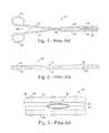
- FIG. 1is a plan view of a conventional clamp.
- FIG. 2is a side view of the clamp illustrated in FIG. 1 .
- FIG. 3is an enlarged view of a portion of the clamp illustrated in FIG. 1 holding a vein.
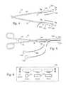
- FIG. 4is plan of a pair of energy transmission assemblies in accordance with a preferred embodiment of a present invention.
- FIG. 5is plan showing the energy transmission assemblies illustrated in FIG. 4 mounted on a clamp.
- FIG. 6is a front view of an electrosurgical unit.
- FIG. 7 ais a section view taken along line 7 a - 7 a in FIG. 4 .
- FIG. 7 bis a section view taken along line 7 b - 7 b in FIG. 4 .
- FIG. 8is a section view taken along line 8 - 8 in FIG. 7 a.
- FIG. 9 ais a section view of an energy transmission assembly in accordance with a preferred embodiment of a present invention.
- FIG. 9 bis a section view of an energy transmission assembly in accordance with a preferred embodiment of a present invention.
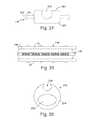
- FIG. 10is a plan view of an energy transmission assembly in accordance with a preferred embodiment of a present invention.
- FIG. 11is a section view taken along line 11 - 11 in FIG. 10 .
- FIG. 12is a section view of an energy transmission assembly in accordance with a preferred embodiment of a present invention.
- FIG. 13is a section view of an energy transmission assembly in accordance with a preferred embodiment of a present invention.
- FIG. 14is a section view taken along line 14 - 14 in FIG. 13 .
- FIG. 15is a section view of an energy transmission assembly in accordance with a preferred embodiment of a present invention.
- FIG. 16 ais a section view of an energy transmission assembly in accordance with a preferred embodiment of a present invention.
- FIG. 16 bis a section view of an energy transmission assembly in accordance with a preferred embodiment of a present invention.
- FIG. 17is a section view of a probe support device in accordance with a preferred embodiment of a present invention.
- FIG. 18is a section view taken along line 18 - 18 in FIG. 17 .
- FIG. 19is a partial plan view showing a pair of the probe support devices illustrated in FIG. 17 supporting a pair of probes on a clamp.
- FIG. 20is a plan view showing a pair of the probe support devices illustrated in FIG. 17 supporting a pair of probes on a clamp.
- FIG. 21is a section view of a probe support device in accordance with a preferred embodiment of a present invention.
- FIG. 22is a section view taken along line 21 - 21 in FIG. 20 .
- FIG. 23is a section view of a probe support device in accordance with a preferred embodiment of a present invention.
- FIG. 24is an end view of a probe support device in accordance with a preferred embodiment of a present invention.
- FIG. 25is a plan view of a probe support device illustrated in FIG. 24 .
- FIG. 26is an end view of a probe support device in accordance with a preferred embodiment of a present invention.
- FIG. 27is a plan view of a clamp in accordance with a preferred embodiment of a present invention.
- FIG. 28is a plan view of a mandrel in accordance with a preferred embodiment of a present invention.
- FIG. 29is a side view of the mandrel illustrated in FIG. 28 .
- FIGS. 30 and 31are plan views of the clamp illustrated in FIG. 27 being bent with the mandrel illustrated in FIG. 28 .
- FIG. 32is a plan view showing one example of how the clamp illustrated in FIG. 27 may be bent.
- FIG. 33is a plan view showing another example of how the clamp illustrated in FIG. 27 may be bent.
- FIG. 34is a plan view of a clamp in accordance with a preferred embodiment of a present invention.
- This specificationdiscloses a number of structures, mainly in the context of cardiac ablation, because the structures are well suited for use with myocardial tissue. Nevertheless, it should be appreciated that the structures are applicable for use in therapies involving other types of soft tissue. For example, various aspects of the present inventions have applications in procedures concerning other regions of the body such as the prostate, liver, brain, gall bladder, uterus and other solid organs.
- Energy transmission assemblies in accordance with a present inventionmay be used to covert a conventional clamp into a tissue coagulation device.
- the energy transmission assembliesmay also be used to covert a clamp in accordance with the inventions described in Section V below into a tissue coagulation device.
- FIGS. 1-3One example of a conventional clamp that may be used in conjunction with the present inventions is generally represented by reference numeral 10 in FIGS. 1-3 .
- the clamp 10includes a pair of rigid arms 12 and 14 that are pivotably connected to one another by a pin 16 .
- the proximal ends of the arms 12 and 14are respectively connected to a pair handle members 18 and 20 , while the distal ends are respectively connected to a pair of rigid clamp members 22 and 24 .
- a locking device 26locks the clamp in the closed orientation, and prevents the clamp members 22 and 24 from coming any closer to one another than is illustrated in FIG. 1 , thereby defining a predetermined spacing between the clamp members.
- the clamp 10also includes a pair of soft, deformable inserts 28 and 30 that are removably carried by the clamp members 22 and 24 .
- the inserts 28 and 30allow clamp 10 to firmly grip a bodily structure 32 without damaging the bodily structure.
- the inserts 28 and 30include mating structures 34 that extend through corresponding apertures 36 in the clamp members 22 and 24 to hold the inserts in place.
- an apparatus 100 for converting the clamp 10 (which has had the inserts 28 and 30 removed) into a bi-polar tissue coagulation deviceincludes a pair of energy transmission assemblies 102 and 104 .
- Each of the energy transmission assembliesincludes a base member 106 that may be removably secured to one of the clamp members 22 and 24 and an energy transmission device 108 .
- the energy transmission devices 108are discussed in greater detail in Section 11 below.
- the configuration of the energy transmission assemblies 102 and 104may vary from application to application to suit particular situations, the energy transmission assemblies in the exemplary embodiment are configured such that they will abut one another in the same manner as the inserts 28 and 30 ( FIGS. 1-3 ) when the clamp 10 is in the closed orientation illustrated in FIG. 5 . Such an arrangement will allow the energy transmission assemblies 102 and 104 to grip a bodily structure in the same manner as the inserts 28 and 30 .
- the exemplary base members 106are preferably formed from a soft, resilient, low durometer material that is electrically insulating. Suitable materials include polyurethane, silicone and polyurethane/silicone blends having a hardness of between about 20 Shore D and about 72 Shore D. Referring to FIGS. 7 a , 7 b and 8 , each of the exemplary base members 106 includes a longitudinally extending aperture 110 into which one of the clamp members 22 and 24 may be inserted. The apertures 110 should be sized and shaped such that the base members 106 will be forced to stretch when the clamp members 22 and 24 are inserted. If, for example, the apertures 110 have the same cross-sectional shape as the clamp members 22 and 24 (e.g.
- the apertures 110should be slightly smaller in their cross-sectional dimensions than the corresponding clamp members.
- the stretching of the apertures 110creates a tight interference fit between the base members 106 and clamp members 22 and 24 .
- the apertures 110may have a semi-circular cross-section in the exemplary embodiment, the apertures may have a round, rectangular, square or elliptical cross-section, or define any other cross-sectional shape, depending on the particular application.
- the exemplary base members 106also include slots 112 ( FIG. 8 ) that secure the energy transmission devices 108 in place.
- the configuration of a slot 112will, of course, depend on the configuration of the energy transmission device 108 that it is holding.
- the illustrated energy transmission device 108is generally cylindrical in shape and the slot 112 has a corresponding arcuate cross-sectional shape.
- the arcis preferably greater than 180 degrees so that the base member 106 will deflect when the energy transmission device 108 is inserted into the slot 112 and then snap back to hold the energy transmission device in place.
- Adhesivemay also be used to secure the energy transmission devices 108 , especially in those instances where the arc is less than 180 degrees.
- FIGS. 9 a and 9 bAnother exemplary apparatus for converting the clamp 10 (which has had the inserts 28 and 30 removed) into a bi-polar tissue coagulation device is illustrated in FIGS. 9 a and 9 b .
- the apparatusincludes a pair of energy transmission assemblies 114 and 116 which are substantially similar to the energy transmission assemblies 102 and 104 and similar elements are represented by similar reference numerals.
- Each of the energy transmission assemblies 114 and 116includes a base member 106 that may be removably secured to one of the clamp members 22 and 24 and an energy transmission device 108 .
- the base members 106 ′are secured to the clamp members 22 and 24 with mating structures 118 that mechanically engage the clamp members.
- the exemplary mating structures 118which are preferably integral with the base members 106 ′ and formed from the same resilient material, include a relatively narrow portion 120 and a relatively wide portion 122 .
- the relatively narrow portionsare approximately the same size as the clamp member apertures 36 and the relatively wide portions 122 are slightly larger than the clamp member apertures.
- a removable connectionis made by urging the mating structures 118 into one end of the apertures 36 , thereby deforming the relatively wide portions 122 , and then urging the base members 106 ′ against the clamp members 22 and 24 until the relatively wide portions exit through the other end of the apertures and reassume their original shape.
- the exemplary mating structures 118may also be reconfigured by eliminating the relatively wide portions 122 and enlarging the relatively narrow portions 120 such that the relatively narrow portions will create an interference fit within the clamp member apertures 36 .
- longitudinally extending mating structureswhich also create an interference fit, may be employed when longitudinally extending slots are formed in the clamp members.
- Another alternativeis to provide the clamp members with one or more small mating structures that extend outwardly therefrom. The clamp member mating structures will be received within apertures or slots formed in the base member.
- an energy transmission assembly 124may be used to convert the clamp 10 (which has had the inserts 28 and 30 removed) into a uni-polar tissue coagulation device.
- the energy transmission assembly 124includes a base member 126 , which may be removably secured to both of the clamp members 22 and 24 , and a plurality of spaced energy transmission devices 108 .
- the configuration of the energy transmission assembly 124may vary from application to application to suit particular situations, the energy transmission assembly in the exemplary embodiment is configured such that it will abut each of the clamp members when the clamp 10 is in the closed orientation illustrated in FIG. 10 .
- the exemplary base member 126is preferably formed from a soft, resilient, low durometer material that is electrically insulating. Suitable materials include polyurethane, silicone and polyurethane/silicone blends having a hardness of between about 20 Shore D and about 72 Shore D.
- a slot 128secures the energy transmission devices 108 in place. Although the configuration of the slot 128 will depend on the configuration of the energy transmission devices 108 , the exemplary slot has an arcuate cross-sectional shape that conforms to the shape of the exemplary cylindrical energy transmission devices. The arc is preferably greater than 180 degrees so that the base member 126 will deflect when the energy transmission devices 108 are inserted into the slot 128 and then snap back to hold the energy transmission devices in place. Adhesive may also be used to secure the energy transmission devices 108 in place, especially in those instances where the are is less than 180 degrees.
- the base member 126is removably secured to the clamp members 22 and 24 with two sets of the mating structures 118 that are described above with reference to FIGS. 9 a and 9 b (with or without the relatively wide portions 122 ).
- the energy transmission assembly 124may be provided with longitudinally extending mating structures 130 that extend outwardly from the base member 126 ′.
- the longitudinally extending mating structures 130which are preferably integral with the base member 126 ′ and formed from the same resilient material, are sized and shaped to create an interference fit with the slots 38 .
- Still another alternativeis to provide the clamp members with one or more small mating structures that are received within apertures or slots formed in the base member.
- the energy transmission assembly 132includes a base member 134 that is preferably formed from a soft, resilient, low durometer material and a plurality of energy transmission devices 108 .
- the material which forms the base member 134should also be electrically insulating. Suitable materials include polyurethane, silicone and polyurethane/silicone blends having a hardness of between about 20 Shore D and about 72 Shore D.
- a slot 128which secures the energy transmission devices 108 in place in the manner described above with reference to FIGS. 10 and 11 , is also provided.
- the exemplary base member 134includes a longitudinally extending aperture 136 into which both of the clamp members 22 and 24 may be inserted.
- the aperture 136should be sized and shaped such that the base member 134 will be forced to stretch when the clamp members 22 and 24 are inserted with the clamp 10 in a closed orientation. The stretching creates a tight interference fit between the base member 134 and the clamp members 22 and 24 .
- the apertures 110have an elliptical cross-section in the exemplary embodiment, the apertures may have a round, rectangular, square or semi-circular cross-section, or define any other cross-sectional shape, depending on the particular application.
- the length of the base members in the exemplary energy transmission assemblieswill vary according to the intended application. In the area of cardiovascular treatments, it is anticipated that suitable lengths will range from, but are not limited to, about 2 cm to about 10 cm.
- the exemplary energy transmission assemblies described abovemay also be modified in a variety of ways.
- the energy transmission assembly illustrated in FIGS. 10 and 11may be converted into a bi-polar device by simply adding a second slot 128 that is preferably spaced apart from and parallel to the existing slot.
- the second slot 128could, for example, include a single return energy transmission device 108 or a plurality of spaced return energy transmission devices.
- the base members and energy transmission devices in the illustrated embodimentsare configured such that the energy transmission devices are generally linear and parallel to the longitudinal axis of the base members (when the assemblies are in a relaxed state and not being urged against a body structure).
- the base members and/or energy transmission devicesmay be reconfigured such that the energy transmission devices, or a portion thereof, are curved and/or non-parallel to the longitudinal axis of the base members when in the relaxed state.
- the energy transmission devicesare electrodes. More specifically, the energy transmission devices are preferably in the form of wound, spiral coil electrodes that are relatively flexible.
- the coilsare made of electrically conducting material, like copper alloy, platinum, or stainless steel, or compositions such as drawn-filled tubing (e.g. a copper core with a platinum jacket).
- the electrically conducting material of the coilscan be further coated with platinum-iridium or gold to improve its conduction properties and biocompatibility.
- a preferred coil electrode configurationis disclosed in U.S. Pat. No. 5,797,905. Although the diameter of the electrodes will very from application to application, the diameter preferably ranges from about 1 mm to about 3 mm for cardiovascular applications.
- the electrodesmay be in the form of solid rings of conductive material, like platinum, or can comprise a conductive material, like platinum-iridium or gold, coated upon the base member using conventional coating techniques or an ion beam assisted deposition (IBAD) process. For better adherence, an undercoating of nickel or titanium can be applied.
- the electrodescan also be in the form of helical ribbons.
- the electrodescan also be formed with a conductive ink compound that is pad printed onto a non-conductive tubular body.
- a preferred conductive ink compoundis a silver-based flexible adhesive conductive ink (polyurethane binder), however other metal-based adhesive conductive inks such as platinum-based, gold-based, copper-based, etc., may also be used to form electrodes. Such inks are more flexible than epoxy-based inks.
- the length of the base memberwill depend on the length of the base member and the intended application.
- the electrodeswill preferably be about 10 mm to about 40 mm in length.
- the electrodeswill be 25 mm in length with 1 mm to 2 mm spacing, which will result in the creation of continuous lesion patterns in tissue when coagulation energy is applied simultaneously to adjacent electrodes.
- the length of the each electrodecan vary from about 3 mm to about 10 mm. Using multiple rigid electrodes longer than about 10 mm each adversely effects the overall flexibility of the device, while electrodes having lengths of less than about 2 mm do not consistently form the desired continuous lesion patterns.
- Electrodesmay be substituted for the electrodes.
- Another type of energy transmission device that may be substituted for the electrodesis cryotemperature elements. Here, the energy transmission is the removal of heat from the tissue.
- Still another type of energy transmission device that may be substituted for the electrodesis needle projections for chemical ablation (which are preferably about 1 to 2 mm in length). Here, the energy transmission is the transmission of chemical energy.
- each energy transmission device 108is individually coupled to a wire 137 ( FIG. 8 ) that conducts coagulating energy.
- the wires 137pass in conventional fashion through cables 138 to an associated connector ( 140 or 142 ).
- the connectors 140 and 142are configured to plug into an electrosurgical unit (“ESU”) 144 that supplies and controls power, such RF power.
- ESUelectrosurgical unit
- a suitable ESUis the Model 4810 ESU sold by EP Technologies, Inc. of San Jose, Calif.
- the exemplary ESU 144 illustrated in FIG. 6includes a plurality of displays and buttons that are used to control the level of power supplied to the energy transmission device(s) 108 and the temperature at the energy transmission device(s).
- the ESU 144may also be used to selectively control which of the energy transmission devices receive power.
- the amount of power required to coagulate tissueranges from 5 to 150 w.
- the exemplary ESU 144 illustrated in FIG. 6is operable in a bi-polar mode, where tissue coagulation energy emitted by the energy transmission device(s) 108 on one energy transmission assembly is returned through the energy transmission device(s) on another energy transmission assembly, and a uni-polar mode, where the tissue coagulation energy emitted by the energy transmission device(s) on an energy transmission assembly is returned through one or more indifferent electrodes (not shown) that are externally attached to the skin of the patient with a patch or one or more electrodes (not shown) that are positioned in the blood pool.
- the exemplary ESU 144is provided with a power output connector 141 and a pair of return connectors 143 .
- the ESU output and return connectors 141 and 143have different shapes to avoid confusion and the connectors 140 and 142 have corresponding shapes.
- the connector 140 associated with energy transmission assembly 102has a shape corresponding to the ESU output connector 141 and the connector 142 associated with energy transmission assembly 104 has a shape corresponding to the ESU return connector 143 .
- the connector (not shown) associated with the energy transmission assembly 124 illustrated in FIG. 10which is intended to be operated in the uni-polar mode, would have a shape corresponding to the ESU output connector 141 .
- a second energy transmission assemblymay be provided with a connector having a shape corresponding to the ESU return connector 143 .
- the assemblywould be provided with a pair of connectors. One would have a shape corresponding to the ESU output connector 141 and the other would have a shape corresponding to the ESU return connector 143 .
- one or more temperature sensors 146may be located on, under, abutting the longitudinal end edges of, or in between, the energy transmission devices 108 .
- a reference thermocouple(not shown) may also be provided.
- signals from the temperature sensors 146are transmitted to the ESU 144 by way of wires 148 ( FIG. 8 ) that are connected to the connector 140 and, in some instances, the connector 142 .
- the wires 137 and 148(which are not shown in all of the Figures for clarity purposes) run through wire apertures 150 and small holes 152 , which are formed in the base members 106 , 126 , 126 ′, 134 and 134 ′.
- Suitable temperature sensors and power control schemesthat are based on a sensed temperature are disclosed in U.S. Pat. Nos. 5,456,682, 5,582,609 and 5,755,715.
- both of the energy transmission assemblies 102 and 104include a single energy transmission device 108 and the energy transmission assembly 102 includes a plurality of spaced temperature sensors 146 .
- the level of power supplied to the energy transmission device 108 on the energy transmission assembly 102would be controlled based on the highest temperature measured by the temperature sensors 146 .
- the energy transmission assembly 104(which is being used as the return) may also provided with a plurality of spaced temperature sensors 146 .
- the level of power supplied to the energy transmission device 108 on the energy transmission assembly 102would be controlled based on the highest temperature measured by any of the temperature sensors 146 , whether on the transmitting assembly 102 or the return assembly 104 .
- a temperature sensor 146may be associated with each of the energy transmission devices.
- power to the energy transmission devices 108may be individually controlled based on the temperature measured by the associated temperature sensor 146 .
- FIGS. 16 a and 16 bAnother exemplary bi-polar arrangement, which is illustrated in FIGS. 16 a and 16 b , is substantially similar to the arrangement illustrated in FIGS. 7 a and 7 b and similar reference numerals are used to represent similar elements.
- the energy transmission assembly 102 ′includes a plurality of spaced energy transmission device 108 , each having a temperature sensor 146 associated therewith, and the energy transmission assembly 104 ′ includes a single energy transmission device 108 and a plurality of temperature sensors 146 .
- the temperature sensors 146are preferably positioned such that, when in use, the temperature sensors on the energy transmission assembly 102 ′ will be aligned with the temperature sensors on the energy transmission assembly 104 ′.
- Such an arrangementallows power to the energy transmission devices 108 on the assembly 102 ′ to be individually controlled based on the highest of two temperatures, i.e. the temperature measured by the temperature sensor 146 associated with the particular energy transmission device and the temperature measured by the temperature sensor directly across from the particular energy transmission device.
- Energy transmission devices in accordance with the present inventionsmay also include apparatus that cools the tissue during tissue coagulation procedures.
- suitable cooling apparatusare illustrated in FIGS. 13-15 .
- tissue cooling apparatusmay also be used in conjunction with the exemplary devices illustrated in FIGS. 4, 5, 7 a - 12 , 16 a and 16 b .
- the tissue cooling apparatus disclosed hereinemploy conductive fluid to cool tissue during coagulation procedures. More specifically, and as described below and in U.S. application Ser. No. 09/761,981 (which is incorporated herein by reference), heat from the tissue being coagulated is transferred to ionic fluid to cool the tissue while energy is transferred from an electrode or other energy transmission device to the tissue through the fluid by way of ionic transport.
- the conductive fluidmay be pumped through the tissue cooling apparatus ( FIGS. 13 and 14 ) or the tissue cooling apparatus may be saturated with the fluid prior to use ( FIG. 15 ). In either case, cooling tissue during a coagulation procedure facilitates the formation of lesions that are wider and deeper than those that could be realized with an otherwise identical device which lacks tissue cooling apparatus.
- an exemplary tissue cooling apparatus 154includes a nanoporous outer casing 156 through which ionic fluid (represented by arrows F) is transferred.
- the ionic fluidpreferably flows from one longitudinal end of the tissue cooling apparatus 154 to the other.
- the outer casing 156is secured to the base member 134 over the energy transmission devices 108 such that a fluid transmission space 158 is defined therebetween. More specifically, the proximal and distal ends of the outer casing 156 are secured to the base member 134 with anchoring devices (not shown) such as lengths of heat shrink tubing, Nitinol tubing or other mechanical devices that form an interference fit between the casing and the base member. Adhesive bonding is another method of securing the outer casing 156 to the base member 134 .
- the fluid transmission spacewill typically be about 0.5 mm to about 2.0 mm high and slightly wider than the associated energy transmission device(s) 108 .
- the ionic fluidis supplied under pressure from a fluid source (not shown) by way of a supply line 160 and is returned to the source by way of a return line 162 .
- the supply line 160is connected to a fluid lumen 164 that runs from the proximal end of the base member 134 to the distal region of the outer casing 156 .
- the fluid lumen 164is connected to the fluid transmission space 158 by an aperture 166 .
- the electrically conductive ionic fluidpreferably possesses a low resistivity to decrease ohmic loses, and thus ohmic heating effects, within the outer casing 156 .
- the composition of the electrically conductive fluidcan vary.
- the fluidis a hypertonic saline solution, having a sodium chloride concentration at or near saturation, which is about 5% to about 25% weight by volume.
- Hypertonic saline solutionhas a relatively low resistivity of only about 5 ohm-cm, as compared to blood resistivity of about 150 ohm-cm and myocardial tissue resistivity of about 500 ohm-cm.
- the ionic fluidcan be a hypertonic potassium chloride solution.
- a suitable inlet temperature for epicardial applications(the temperature will, of course, rise as heat is transferred to the fluid) is about 0 to 25° C. with a constant flow rate of about 2 to 20 ml/min.
- the flow rate required for endocardial applications where blood is presentwould be about three-fold higher (i.e. 6 to 60 ml/min.). Should applications so require, a flow rate of up to 100 ml/min. may be employed.
- a volume of fluid between about 200 and 500 ml within the bagwill remain at room temperature (about 22° C.) when the flow rate is between about 2 ml/min. and 20 ml/min.
- the flexible bagshould include enough fluid to complete the procedure. 160 ml would, for example, be required for a 20 minute procedure where the flow rate was 8 ml/min.
- the fluid pressure within the outer casing 156should be about 30 mm Hg in order to provide a structure that will resiliently conform to the tissue surface in response to a relatively small force normal to the tissue. Pressures above about 100 mm Hg will cause the outer casing 156 to become too stiff to properly conform to the tissue surface. For that reason, the flow resistance to and from the outer casing 156 should be relatively low.
- the pores in the nanoporous outer casing 156allow the transport of ions contained in the fluid through the casing and into contact with tissue.
- an energy transmission device 108transmit RF energy into the ionic fluid
- the ionic fluidestablishes an electrically conductive path through the outer casing 156 to the tissue being coagulated.
- Regenerated cellulose membrane materialstypically used for blood oxygenation, dialysis or ultrafiltration, are a suitable nanoporous material for the outer casing 156 .
- the thickness of the materialshould be about 0.002 to 0.005 inch.
- regenerated celluloseis electrically non-conductive, the relatively small pores of this material allow effective ionic transport in response to the applied RF field. At the same time, the relatively small pores prevent transfer of macromolecules through the material, so that pressure driven liquid perfusion is less likely to accompany the ionic transport, unless relatively high pressure conditions develop within the outer casing 156 .
- Hydro-FluoroTM materialwhich is disclosed in U.S. application Ser. No. 09/573,071, filed May 16, 2000, is another material that may be used.
- Materialssuch as nylons (with a softening temperature above 100° C.), PTFE, PEI and PEEK that have nanopores created through the use of lasers, electrostatic discharge, ion beam bombardment or other processes may also be used. Such materials would preferably include a hydrophilic coating.
- Nanoporous materialsmay also be fabricated by weaving a material (such as nylon, polyester, polyethylene, polypropylene, fluorocarbon, fine diameter stainless steel, or other fiber) into a mesh having the desired pore size and porosity. These materials permit effective passage of ions in response to the applied RF field. However, as many of these materials possess larger pore diameters, pressure driven liquid perfusion, and the attendant transport of macromolecules through the pores, are also more likely to occur.
- the electrical resistivity of the outer casing 156will have a significant influence on lesion geometry and controllability.
- Low-resistivity(below about 500 ohm-cm) requires more RF power and results in deeper lesions, while high-resistivity (at or above about 500 ohm-cm) generates more uniform heating and improves controllability. Because of the additional heat generated by the increased body resistivity, less RF power is required to reach similar tissue temperatures after the same interval of time. Consequently, lesions generated with high-resistivity structures usually have smaller depth.
- the electrical resistivity of the outer casingcan be controlled by specifying the pore size of the material, the porosity of the material, and the water adsorption characteristics (hydrophilic versus hydrophobic) of the material. A detailed discussion of these characteristics is found in U.S. Pat. No. 5,961,513.
- a suitable electrical resistivity for epicardial and endocardial lesion formationis about 1 to 3000 ohm-cm measured wet.
- liquid perfusion through the nanoporous outer casing 156is preferred.
- ionic transportcreates a continuous virtual electrode at the tissue interface.
- the virtual electrodeefficiently transfers RF energy without need for an electrically conductive metal surface.
- Pore diameters smaller than about 0.1 ⁇ mretain macromolecules, but allow ionic transfer through the pores in response to the applied RF field. With smaller pore diameters, pressure driven liquid perfusion through the pores is less likely to accompany the ionic transport, unless relatively high pressure conditions develop within the outer casing 156 . Larger pore diameters (up to 8 ⁇ m) can also be used to permit ionic current flow across the membrane in response to the applied RF field. With larger pore diameters, pressure driven fluid transport across the membrane is much higher and macromolecules (such as protein) and even small blood cells (such as platelets) could cross the membrane and contaminate the inside of the probe. Red blood cells would normally not cross the membrane barrier, even if fluid perfusion across the membrane stops.
- macromoleculessuch as protein
- small blood cellssuch as platelets
- a pore diameter of 1 to 5 ⁇ mis suitable for epicardial and endocardial lesion formation. Where a larger pore diameter is employed, thereby resulting in significant fluid transfer through the porous region, a saline solution having a sodium chloride concentration of about 0.9% weight by volume would be preferred.
- porositywhich represents the volumetric percentage of the outer casing 156 that is composed of pores and not occupied by the casing material
- the magnitude of the porosityaffects electrical resistance.
- Low-porosity materialshave high electrical resistivity, whereas high-porosity materials have low electrical resistivity.
- the porosity of the outer casing 156should be at least 1% for epicardial and endocardial applications employing a 1 to 5 ⁇ m pore diameter.
- hydrophilic materialsare generally preferable because they possess a greater capacity to provide ionic transfer of RF energy without significant liquid flow through the material.
- the exemplary tissue cooling apparatus 168 illustrated in FIG. 15consists of a wettable fluid retention element 170 that is simply saturated with ionic fluid (such as saline) prior to use, as opposed to having the fluid pumped through the apparatus in the manner described above with reference to FIGS. 13 and 14 .
- the energy transmission device(s) 108are carried within the fluid retention element 170 .
- Suitable materials for the fluid retention element 170include biocompatible fabrics commonly used for vascular patches (such as woven Dacron®) open cell foam materials, hydrogels, nanoporous balloon materials (with very slow fluid delivery to the surface), and hydrophilic nanoporous materials.
- the effective electrical resistivity of the fluid retention element 170 when wetted with 0.9% saline (normal saline)should range from about 1 ⁇ -cm to about 2000 ⁇ -cm.
- a preferred resistivity for epicardial and endocardial proceduresis about 1000 ⁇ -cm.
- Probe support devices in accordance with a present inventionmay be used to covert a conventional clamp, or a clamp in accordance with the inventions described in Section V below, into a tissue coagulation device by securing one or more conventional catheters, surgical probes, or other apparatus that support energy transmission devices, to the clamp.
- the configuration of the probe support devicesmay vary from application to application to suit particular situations, the exemplary probe support devices are configured such that the probes being supported will abut one another in the same manner as the inserts 28 and 30 ( FIGS. 1-3 ) when the associated clamp is in the closed orientation. Such an arrangement will allow the energy transmission devices on the probes to face one another in the manner similar to that described in Section I above.
- a probe support device 172in accordance with one embodiment of a present invention includes a base member 174 , a slot 176 configured to receive an electrode supporting device such as a catheter or surgical probe, and a plurality of mating structures 178 that mechanically engage a clamp member.
- the exemplary base member 174is preferably formed from a soft, resilient, low durometer material that is electrically insulating. Suitable materials include polyurethane, silicone and illustrated in FIGS. 17 and 18 and similar structural element are represented by similar reference numerals.
- the exemplary probe support device 190may also be used in the manner described above with reference to FIGS. 19 and 20 .
- the mating structures 178have been eliminated and the base member 172 is provided with a longitudinally extending aperture 192 into which one of the clamp members 22 and 24 may be inserted.
- the aperture 192should be sized and shaped such that the base member 174 ′ will be forced to stretch when one of the clamp members 22 and 24 is inserted. If, for example, the apertures 192 have the same cross-sectional shape as the clamp members 22 and 24 (e.g. both are elliptical), then the apertures should be slightly smaller in their cross-sectional dimensions than the corresponding clamp members. The stretching of base member 174 ′ creates a tight interference fit between the base member and the clamp member. Additionally, although the aperture 192 has a semi-circular cross-section in the exemplary embodiment, the apertures may have a round, rectangular, square or elliptical cross-section, or define any other cross-sectional shape, depending on the particular application.
- the probe support device 172may be provided with a longitudinally extending mating structure 194 that extends outwardly from the base member 174 .
- the longitudinally extending mating structure 194which is preferably integral with the base member 174 and formed from the same resilient material, is sized to create an interference fit with a slot.
- Still another alternativeis to provide the clamp members with one or more small mating structures that are received within apertures or slots formed in the base member 174 .
- FIGS. 24 and 25An exemplary probe support device 196 that may be used in conjunction with a probe 184 to convert the clamp 10 (which has had the inserts 28 and 30 removed) into a uni-polar tissue coagulation device is illustrated in FIGS. 24 and 25 .
- the configuration of the probe support device 196may vary from application to application to suit particular situations, the probe support device in the exemplary embodiment is configured such that it will abut each of the clamp members 22 and 24 when the clamp is in the closed orientation illustrated in FIG. 25 .
- the exemplary probe support device 196includes a base member 198 , a slot 200 configured to receive a probe 184 or other electrode supporting device, and a plurality of mating structures 178 that mechanically engage a clamp members 22 and 24 in the manner described above.
- the exemplary base member 198is preferably formed from a soft, resilient, low durometer material that is electrically insulating. Suitable materials include polyurethane, silicone and polyurethane/silicone blends having a hardness of between about 20 Shore D and about 72 Shore D.
- the size and shape of the slot 200will depend on the size and shape of the probe that it is intended to hold.
- the exemplary probe 184is generally cylindrical in shape and, according, the exemplary slot 200 has a corresponding arcuate cross-sectional shape. The arc is preferably greater than 180 degrees so that the base member 198 will deflect when the probe 184 is inserted into the slot 200 and then snap back to hold the probe in place.
- the probe support device 202includes a base member 204 , a slot 206 configured to receive a probe 184 or other electrode supporting device, and a longitudinally extending aperture 208 into which both of the clamp members 22 and 24 may be inserted.
- the exemplary base member 204is preferably formed from a soft, resilient, low durometer material that is electrically insulating. Suitable materials include polyurethane, silicone and polyurethane/silicone blends having a hardness of between about 20 Shore D and about 72 Shore D.
- the size and shape of the slot 206will depend on the size and shape of the probe that it is intended to hold, as is described above with reference to slot 200 .
- the aperture 208should be sized and shaped such that the base member 204 will be forced to stretch when the clamp members 22 and 24 are inserted with the clamp 10 in a closed orientation. The stretching creates a tight interference fit between the base member 204 and the clamp members 22 and 24 .
- the aperture 208has an elliptical cross-section in the exemplary embodiment, the aperture may have a round, rectangular, square or semi-circular cross-section, or define any other cross-sectional shape, depending on the particular application.
- the length of the base members in the exemplary probe support deviceswill vary according to the intended application. In the area of cardiovascular treatments, it is anticipated that suitable lengths will range from, but are not limited to, about 3 cm to about 10 cm.
- a rigid structureis a structure than cannot be readily bent by a physician.
- a malleable structurecan be readily bent by the physician to a desired shape, without springing back when released, so that it will remain in that shape during the surgical procedure.
- the stiffness of a malleable structuremust be low enough to allow the structure to be bent, but high enough to resist bending when the forces associated with a surgical procedure are applied to the structure.
- Rigid structuresare preferably formed from stainless steel, while malleable structure are preferably farmed from annealed stainless steel or titanium. Additional information concerning malleable structures may be found in U.S. Pat. No. 6,142,994, which is incorporated herein by reference.
- a clamp 210 in accordance with a preferred embodiment of a present inventionincludes a pair of malleable clamp members 212 and 214 .
- the malleable clamp members 212 and 214are carried at the distal ends of a pair of arms 216 and 218 .
- the arms 216 and 218are pivotably secured to one another by a pin 220 to allow the clamp members 212 and 214 to be moved towards and away from one another between opened and closed positions.
- the arms 216 and 218are preferably formed from rigid material, but may also be malleable if desired. When rigid, the arms 216 and 218 may be linear or have a preformed curvature.
- a pair of handles 222 and 224are mounted on the proximal ends of the arms 216 and 218 .
- a locking device 226locks the clamp 210 in the closed orientation illustrated in FIG. 27 .
- the locking device 226also prevents the clamp members 212 and 214 from coming any closer to one another than is illustrated in FIG. 27 , thereby defining a predetermined spacing between the clamp members.
- the malleability of the clamp members 212 and 214allows them to be re-shaped by the physician as needed for particular procedures and body structures. As such, a single clamp 210 is capable of taking the place of a number of conventional clamps with rigid clamp members. In some implementations, the clamp members 212 and 214 will be more malleable (i.e. easier to bend) at their distal end than at their proximal end. This may be accomplished by gradually decreasing the cross-sectional area of each clamp member 212 and 214 from the proximal end to the distal end.
- the clamp members 212 and 214may also be provided with holes 228 ( FIG. 31 ) that allow soft deformable inserts, such as the conventional inserts 28 and 30 described above with reference to FIGS. 1-3 .
- the exemplary clamp 210may also be used in conjunction with the energy transmission assemblies, probe support devices, and probes described in Sections I-IV above.
- the exemplary clamp 210is provided with a malleable insert 230 that is sized and shaped (rectangular in the exemplary implementation) to be held between the malleable clamp members 212 and 214 when the clamp is closed and locked.
- the friction between the clamp members 212 and 214 and insert 230will hold the insert in place during bending.
- the insert 230may be provided with small protrusions that will be received by the holes 228 .
- the malleable insert 2 : 30which is preferably formed from the same material as the malleable clamp members 212 and 214 , will bend with the clamp members during the bending process, thereby maintaining the predetermined spacing. [Note FIG. 32 .]
- the exemplary mandrel 232 illustrated in FIGS. 28 and 29may be used to bend the malleable clamp members 212 and 214 .
- the exemplary mandrel 232includes a base 234 and a pair of cylindrical posts 236 and 238 . Posts of other shapes, such as elliptical posts, may also be employed to achieve particular bends.
- the mandrel 232should also be formed from material that is harder than the malleable clamp members 212 and 214 , such as stainless steel or titanium.
- the exemplary mandrel 232may be used to bend the malleable clamp members 212 and 214 in the manners illustrated in FIGS. 30 and 31 .
- the clamp 210may be rotated in the direction of the arrow (or in the opposite direction) until the damp members 212 and 214 are bent the desired amount.
- the damp 210may then moved longitudinally and the bending process repeated until the desired bend, such as the exemplary bend illustrated in FIG. 32 , has been achieved.
- the clamp 210can be rotated about its longitudinal axis and bent in other planes, as is illustrated for example in FIGS.
- the malleable clamp members 212 and 214may be bent independently of one another and/or into different shapes.
- the physicianwill simply place the mandrel 232 on a suitable surface and press down the base 234 during a bending procedure.
- structuremay be provided to secure the mandrel 232 to the surface.
- FIG. 34Another example of a clamp in accordance with a preferred embodiment of a present invention is generally represented by reference numeral 240 in FIG. 34 .
- Clamp 240is similar to clamp 210 and similar elements are represented by similar reference numerals.
- the exemplary clamp 240includes malleable clamp members 212 and 214 , pivotable arms 216 and 218 , handles 222 and 224 , and a locking device 226 .
- the arms 216 and 218are pivotably carried by one end of an elongate housing 242 and the malleable damp) members 212 and 214 are carried by a pair of supports 244 and 246 that are pivotably carried the other end of the housing.
- a suitable mechanical linkagelocated within the housing 242 causes the supports 244 and 246 (and clamp members 212 and 214 ) to move relative to one another in response to movement of the arms 216 and 218 .
- the housing 242may be rigid or malleable
- the present clamps with malleable clamp membershave a wide variety of applications.
- One exampleis the formation of transmural epicardial lesions to isolate the sources of focal (or ectopic) atrial fibrillation and, more specifically, the creation of transmural lesions around the pulmonary veins.
- Energy transmission devicesmay be permanently affixed to the malleable clamp members. Energy transmission devices may also be added using the structures described in Sections I-IV above and the clamp may be used a clamp or as a surgical probe, depending on the structure being used in combination with the clamp. Access to the heart may be obtained via a thoracotomy, thoracostomy or median sternotomy. Ports may also be provided for cameras and other instruments.
- Lesionsmay be created around the pulmonary veins individually or, alternatively, lesions may be created around pairs of pulmonary veins. For example, a first transmural epicardial lesion may be created around the right pulmonary vein pair and a second transmural epicardial lesion may be created around the left pulmonary vein pair. Thereafter, if needed, a linear transmural epicardial lesion may be created between the right and left pulmonary vein pairs. A linear transmural lesion that extends from the lesion between the right and left pulmonary vein pairs to the left atrial appendage may also be formed. Alternatively, a single lesion may be formed around all four of the pulmonary veins.
Landscapes
- Health & Medical Sciences (AREA)
- Surgery (AREA)
- Engineering & Computer Science (AREA)
- Life Sciences & Earth Sciences (AREA)
- Medical Informatics (AREA)
- Molecular Biology (AREA)
- Nuclear Medicine, Radiotherapy & Molecular Imaging (AREA)
- Plasma & Fusion (AREA)
- Biomedical Technology (AREA)
- Heart & Thoracic Surgery (AREA)
- Physics & Mathematics (AREA)
- Otolaryngology (AREA)
- Animal Behavior & Ethology (AREA)
- General Health & Medical Sciences (AREA)
- Public Health (AREA)
- Veterinary Medicine (AREA)
- Surgical Instruments (AREA)
- Investigating Or Analysing Biological Materials (AREA)
- Laser Surgery Devices (AREA)
- Automatic Analysis And Handling Materials Therefor (AREA)
Abstract
Description
- I. Energy Transmission Assemblies
- II. Energy Transmission Devices, Temperature Sensing and Power Control
- III. Tissue Cooling Apparatus
- IV. Probe Support devices
- V. Clamp With Malleable Clamp Members
Claims (13)
Priority Applications (1)
| Application Number | Priority Date | Filing Date | Title |
|---|---|---|---|
| US14/083,274US9370395B2 (en) | 2002-02-19 | 2013-11-18 | Ablation clamp with malleable jaws |
Applications Claiming Priority (5)
| Application Number | Priority Date | Filing Date | Title |
|---|---|---|---|
| US10/080,374US7753908B2 (en) | 2002-02-19 | 2002-02-19 | Apparatus for securing an electrophysiology probe to a clamp |
| US12/833,824US8241277B2 (en) | 2002-02-19 | 2010-07-09 | Apparatus for securing an electrophysiology probe to a clamp |
| US13/569,958US20120303027A1 (en) | 2002-02-19 | 2012-08-08 | Apparatus for securing an electrophysiology probe to a clamp |
| US13/686,614US8585701B2 (en) | 2002-02-19 | 2012-11-27 | Apparatus for securing an electrophysiology probe to a clamp |
| US14/083,274US9370395B2 (en) | 2002-02-19 | 2013-11-18 | Ablation clamp with malleable jaws |
Related Parent Applications (1)
| Application Number | Title | Priority Date | Filing Date |
|---|---|---|---|
| US13/686,614ContinuationUS8585701B2 (en) | 2002-02-19 | 2012-11-27 | Apparatus for securing an electrophysiology probe to a clamp |
Publications (2)
| Publication Number | Publication Date |
|---|---|
| US20140214031A1 US20140214031A1 (en) | 2014-07-31 |
| US9370395B2true US9370395B2 (en) | 2016-06-21 |
Family
ID=27733204
Family Applications (5)
| Application Number | Title | Priority Date | Filing Date |
|---|---|---|---|
| US10/080,374Expired - Fee RelatedUS7753908B2 (en) | 2001-12-04 | 2002-02-19 | Apparatus for securing an electrophysiology probe to a clamp |
| US12/833,824Expired - Fee RelatedUS8241277B2 (en) | 2002-02-19 | 2010-07-09 | Apparatus for securing an electrophysiology probe to a clamp |
| US13/569,958AbandonedUS20120303027A1 (en) | 2002-02-19 | 2012-08-08 | Apparatus for securing an electrophysiology probe to a clamp |
| US13/686,614Expired - Fee RelatedUS8585701B2 (en) | 2002-02-19 | 2012-11-27 | Apparatus for securing an electrophysiology probe to a clamp |
| US14/083,274Expired - Fee RelatedUS9370395B2 (en) | 2002-02-19 | 2013-11-18 | Ablation clamp with malleable jaws |
Family Applications Before (4)
| Application Number | Title | Priority Date | Filing Date |
|---|---|---|---|
| US10/080,374Expired - Fee RelatedUS7753908B2 (en) | 2001-12-04 | 2002-02-19 | Apparatus for securing an electrophysiology probe to a clamp |
| US12/833,824Expired - Fee RelatedUS8241277B2 (en) | 2002-02-19 | 2010-07-09 | Apparatus for securing an electrophysiology probe to a clamp |
| US13/569,958AbandonedUS20120303027A1 (en) | 2002-02-19 | 2012-08-08 | Apparatus for securing an electrophysiology probe to a clamp |
| US13/686,614Expired - Fee RelatedUS8585701B2 (en) | 2002-02-19 | 2012-11-27 | Apparatus for securing an electrophysiology probe to a clamp |
Country Status (9)
| Country | Link |
|---|---|
| US (5) | US7753908B2 (en) |
| EP (1) | EP1476089B1 (en) |
| JP (1) | JP2005525847A (en) |
| AT (1) | ATE301430T1 (en) |
| AU (1) | AU2002362066A1 (en) |
| CA (1) | CA2472958A1 (en) |
| DE (1) | DE60205509T2 (en) |
| ES (1) | ES2247416T3 (en) |
| WO (1) | WO2003070119A1 (en) |
Cited By (2)
| Publication number | Priority date | Publication date | Assignee | Title |
|---|---|---|---|---|
| US11678928B2 (en) | 2019-01-10 | 2023-06-20 | Atricure, Inc. | Surgical clamp |
| US11931057B2 (en) | 2020-09-24 | 2024-03-19 | Arthrex, Inc. | Bendable handheld medical actuator |
Families Citing this family (399)
| Publication number | Priority date | Publication date | Assignee | Title |
|---|---|---|---|---|
| US6267761B1 (en)* | 1997-09-09 | 2001-07-31 | Sherwood Services Ag | Apparatus and method for sealing and cutting tissue |
| US7435249B2 (en) | 1997-11-12 | 2008-10-14 | Covidien Ag | Electrosurgical instruments which reduces collateral damage to adjacent tissue |
| US6726686B2 (en) | 1997-11-12 | 2004-04-27 | Sherwood Services Ag | Bipolar electrosurgical instrument for sealing vessels |
| US6352536B1 (en) | 2000-02-11 | 2002-03-05 | Sherwood Services Ag | Bipolar electrosurgical instrument for sealing vessels |
| US6050996A (en) | 1997-11-12 | 2000-04-18 | Sherwood Services Ag | Bipolar electrosurgical instrument with replaceable electrodes |
| US6228083B1 (en)* | 1997-11-14 | 2001-05-08 | Sherwood Services Ag | Laparoscopic bipolar electrosurgical instrument |
| US20030014052A1 (en) | 1997-11-14 | 2003-01-16 | Buysse Steven P. | Laparoscopic bipolar electrosurgical instrument |
| US7267677B2 (en)* | 1998-10-23 | 2007-09-11 | Sherwood Services Ag | Vessel sealing instrument |
| US20040249374A1 (en) | 1998-10-23 | 2004-12-09 | Tetzlaff Philip M. | Vessel sealing instrument |
| US7582087B2 (en) | 1998-10-23 | 2009-09-01 | Covidien Ag | Vessel sealing instrument |
| US7118570B2 (en) | 2001-04-06 | 2006-10-10 | Sherwood Services Ag | Vessel sealing forceps with disposable electrodes |
| US7364577B2 (en) | 2002-02-11 | 2008-04-29 | Sherwood Services Ag | Vessel sealing system |
| EP1372505B1 (en) | 1999-09-01 | 2006-06-21 | Sherwood Services AG | Electrosurgical instrument reducing thermal spread |
| US7887535B2 (en) | 1999-10-18 | 2011-02-15 | Covidien Ag | Vessel sealing wave jaw |
| US20030109875A1 (en) | 1999-10-22 | 2003-06-12 | Tetzlaff Philip M. | Open vessel sealing forceps with disposable electrodes |
| AU2001249937B2 (en) | 2001-04-06 | 2006-02-09 | Covidien Ag | Vessel sealing instrument |
| US7118587B2 (en) | 2001-04-06 | 2006-10-10 | Sherwood Services Ag | Vessel sealer and divider |
| EP1527747B1 (en) | 2001-04-06 | 2015-09-30 | Covidien AG | Electrosurgical instrument which reduces collateral damage to adjacent tissue |
| US10849681B2 (en) | 2001-04-06 | 2020-12-01 | Covidien Ag | Vessel sealer and divider |
| AU2002250551B2 (en) | 2001-04-06 | 2006-02-02 | Covidien Ag | Molded insulating hinge for bipolar instruments |
| US7101372B2 (en)* | 2001-04-06 | 2006-09-05 | Sherwood Sevices Ag | Vessel sealer and divider |
| US7090673B2 (en) | 2001-04-06 | 2006-08-15 | Sherwood Services Ag | Vessel sealer and divider |
| US7101371B2 (en) | 2001-04-06 | 2006-09-05 | Dycus Sean T | Vessel sealer and divider |
| ES2262639T3 (en) | 2001-04-06 | 2006-12-01 | Sherwood Services Ag | SHUTTER AND DIVIDER OF GLASSES WITH BUMPER MEMBERS N OCONDUCTIVES. |
| US7083618B2 (en)* | 2001-04-06 | 2006-08-01 | Sherwood Services Ag | Vessel sealer and divider |
| US7101373B2 (en) | 2001-04-06 | 2006-09-05 | Sherwood Services Ag | Vessel sealer and divider |
| US11229472B2 (en) | 2001-06-12 | 2022-01-25 | Cilag Gmbh International | Modular battery powered handheld surgical instrument with multiple magnetic position sensors |
| US20030018332A1 (en)* | 2001-06-20 | 2003-01-23 | Schmaltz Dale Francis | Bipolar electrosurgical instrument with replaceable electrodes |
| US9072522B2 (en)* | 2001-12-04 | 2015-07-07 | Atricure, Inc. | Adjustable clamp systems and methods |
| US7674258B2 (en)* | 2002-09-24 | 2010-03-09 | Endoscopic Technologies, Inc. (ESTECH, Inc.) | Electrophysiology electrode having multiple power connections and electrophysiology devices including the same |
| US7753908B2 (en) | 2002-02-19 | 2010-07-13 | Endoscopic Technologies, Inc. (Estech) | Apparatus for securing an electrophysiology probe to a clamp |
| US6932816B2 (en)* | 2002-02-19 | 2005-08-23 | Boston Scientific Scimed, Inc. | Apparatus for converting a clamp into an electrophysiology device |
| US7931649B2 (en) | 2002-10-04 | 2011-04-26 | Tyco Healthcare Group Lp | Vessel sealing instrument with electrical cutting mechanism |
| US7270664B2 (en) | 2002-10-04 | 2007-09-18 | Sherwood Services Ag | Vessel sealing instrument with electrical cutting mechanism |
| US7276068B2 (en) | 2002-10-04 | 2007-10-02 | Sherwood Services Ag | Vessel sealing instrument with electrical cutting mechanism |
| US7799026B2 (en) | 2002-11-14 | 2010-09-21 | Covidien Ag | Compressible jaw configuration with bipolar RF output electrodes for soft tissue fusion |
| US7033354B2 (en) | 2002-12-10 | 2006-04-25 | Sherwood Services Ag | Electrosurgical electrode having a non-conductive porous ceramic coating |
| US7357800B2 (en)* | 2003-02-14 | 2008-04-15 | Boston Scientific Scimed, Inc. | Power supply and control apparatus and electrophysiology systems including the same |
| EP1601298B1 (en) | 2003-03-13 | 2016-09-07 | Covidien AG | Bipolar concentric electrode assembly for soft tissue fusion |
| CA2523675C (en) | 2003-05-01 | 2016-04-26 | Sherwood Services Ag | Electrosurgical instrument which reduces thermal damage to adjacent tissue |
| US7160299B2 (en) | 2003-05-01 | 2007-01-09 | Sherwood Services Ag | Method of fusing biomaterials with radiofrequency energy |
| US8128624B2 (en) | 2003-05-01 | 2012-03-06 | Covidien Ag | Electrosurgical instrument that directs energy delivery and protects adjacent tissue |
| JP5137230B2 (en) | 2003-05-15 | 2013-02-06 | コヴィディエン・アクチェンゲゼルシャフト | Tissue sealer with non-conductive variable stop member and method for sealing tissue |
| US7150749B2 (en) | 2003-06-13 | 2006-12-19 | Sherwood Services Ag | Vessel sealer and divider having elongated knife stroke and safety cutting mechanism |
| US7156846B2 (en) | 2003-06-13 | 2007-01-02 | Sherwood Services Ag | Vessel sealer and divider for use with small trocars and cannulas |
| US7150097B2 (en)* | 2003-06-13 | 2006-12-19 | Sherwood Services Ag | Method of manufacturing jaw assembly for vessel sealer and divider |
| USD956973S1 (en) | 2003-06-13 | 2022-07-05 | Covidien Ag | Movable handle for endoscopic vessel sealer and divider |
| US7597693B2 (en) | 2003-06-13 | 2009-10-06 | Covidien Ag | Vessel sealer and divider for use with small trocars and cannulas |
| US7857812B2 (en) | 2003-06-13 | 2010-12-28 | Covidien Ag | Vessel sealer and divider having elongated knife stroke and safety for cutting mechanism |
| US9848938B2 (en) | 2003-11-13 | 2017-12-26 | Covidien Ag | Compressible jaw configuration with bipolar RF output electrodes for soft tissue fusion |
| US7232440B2 (en) | 2003-11-17 | 2007-06-19 | Sherwood Services Ag | Bipolar forceps having monopolar extension |
| US7367976B2 (en)* | 2003-11-17 | 2008-05-06 | Sherwood Services Ag | Bipolar forceps having monopolar extension |
| US7252667B2 (en) | 2003-11-19 | 2007-08-07 | Sherwood Services Ag | Open vessel sealing instrument with cutting mechanism and distal lockout |
| US7500975B2 (en) | 2003-11-19 | 2009-03-10 | Covidien Ag | Spring loaded reciprocating tissue cutting mechanism in a forceps-style electrosurgical instrument |
| US7131970B2 (en) | 2003-11-19 | 2006-11-07 | Sherwood Services Ag | Open vessel sealing instrument with cutting mechanism |
| US7811283B2 (en) | 2003-11-19 | 2010-10-12 | Covidien Ag | Open vessel sealing instrument with hourglass cutting mechanism and over-ratchet safety |
| US7442193B2 (en)* | 2003-11-20 | 2008-10-28 | Covidien Ag | Electrically conductive/insulative over-shoe for tissue fusion |
| US20050119653A1 (en)* | 2003-12-02 | 2005-06-02 | Swanson David K. | Surgical methods and apparatus for forming lesions in tissue and confirming whether a therapeutic lesion has been formed |
| US8002770B2 (en) | 2003-12-02 | 2011-08-23 | Endoscopic Technologies, Inc. (Estech) | Clamp based methods and apparatus for forming lesions in tissue and confirming whether a therapeutic lesion has been formed |
| US8182501B2 (en) | 2004-02-27 | 2012-05-22 | Ethicon Endo-Surgery, Inc. | Ultrasonic surgical shears and method for sealing a blood vessel using same |
| US7780662B2 (en) | 2004-03-02 | 2010-08-24 | Covidien Ag | Vessel sealing system using capacitive RF dielectric heating |
| USD541938S1 (en) | 2004-04-09 | 2007-05-01 | Sherwood Services Ag | Open vessel sealer with mechanical cutter |
| USD533942S1 (en) | 2004-06-30 | 2006-12-19 | Sherwood Services Ag | Open vessel sealer with mechanical cutter |
| US7549988B2 (en) | 2004-08-30 | 2009-06-23 | Boston Scientific Scimed, Inc. | Hybrid lesion formation apparatus, systems and methods |
| US7195631B2 (en) | 2004-09-09 | 2007-03-27 | Sherwood Services Ag | Forceps with spring loaded end effector assembly |
| US7540872B2 (en) | 2004-09-21 | 2009-06-02 | Covidien Ag | Articulating bipolar electrosurgical instrument |
| USD531311S1 (en) | 2004-10-06 | 2006-10-31 | Sherwood Services Ag | Pistol grip style elongated dissecting and dividing instrument |
| USD541418S1 (en) | 2004-10-06 | 2007-04-24 | Sherwood Services Ag | Lung sealing device |
| USD535027S1 (en) | 2004-10-06 | 2007-01-09 | Sherwood Services Ag | Low profile vessel sealing and cutting mechanism |
| USD525361S1 (en) | 2004-10-06 | 2006-07-18 | Sherwood Services Ag | Hemostat style elongated dissecting and dividing instrument |
| US7384421B2 (en)* | 2004-10-06 | 2008-06-10 | Sherwood Services Ag | Slide-activated cutting assembly |
| US7955332B2 (en) | 2004-10-08 | 2011-06-07 | Covidien Ag | Mechanism for dividing tissue in a hemostat-style instrument |
| US20060079879A1 (en) | 2004-10-08 | 2006-04-13 | Faller Craig N | Actuation mechanism for use with an ultrasonic surgical instrument |
| US7628792B2 (en) | 2004-10-08 | 2009-12-08 | Covidien Ag | Bilateral foot jaws |
| USD567943S1 (en) | 2004-10-08 | 2008-04-29 | Sherwood Services Ag | Over-ratchet safety for a vessel sealing instrument |
| USD564662S1 (en)* | 2004-10-13 | 2008-03-18 | Sherwood Services Ag | Hourglass-shaped knife for electrosurgical forceps |
| US7686827B2 (en) | 2004-10-21 | 2010-03-30 | Covidien Ag | Magnetic closure mechanism for hemostat |
| US7727231B2 (en) | 2005-01-08 | 2010-06-01 | Boston Scientific Scimed, Inc. | Apparatus and methods for forming lesions in tissue and applying stimulation energy to tissue in which lesions are formed |
| US7686804B2 (en) | 2005-01-14 | 2010-03-30 | Covidien Ag | Vessel sealer and divider with rotating sealer and cutter |
| US7909823B2 (en) | 2005-01-14 | 2011-03-22 | Covidien Ag | Open vessel sealing instrument |
| US7892228B2 (en)* | 2005-02-25 | 2011-02-22 | Boston Scientific Scimed, Inc. | Dual mode lesion formation apparatus, systems and methods |
| US7491202B2 (en) | 2005-03-31 | 2009-02-17 | Covidien Ag | Electrosurgical forceps with slow closure sealing plates and method of sealing tissue |
| US8945151B2 (en) | 2005-07-13 | 2015-02-03 | Atricure, Inc. | Surgical clip applicator and apparatus including the same |
| US7837685B2 (en) | 2005-07-13 | 2010-11-23 | Covidien Ag | Switch mechanisms for safe activation of energy on an electrosurgical instrument |
| US7628791B2 (en) | 2005-08-19 | 2009-12-08 | Covidien Ag | Single action tissue sealer |
| US7922953B2 (en) | 2005-09-30 | 2011-04-12 | Covidien Ag | Method for manufacturing an end effector assembly |
| US7789878B2 (en) | 2005-09-30 | 2010-09-07 | Covidien Ag | In-line vessel sealer and divider |
| US7722607B2 (en) | 2005-09-30 | 2010-05-25 | Covidien Ag | In-line vessel sealer and divider |
| ES2381560T3 (en) | 2005-09-30 | 2012-05-29 | Covidien Ag | Insulating sleeve for electrosurgical forceps |
| CA2561034C (en) | 2005-09-30 | 2014-12-09 | Sherwood Services Ag | Flexible endoscopic catheter with an end effector for coagulating and transfecting tissue |
| US7879035B2 (en) | 2005-09-30 | 2011-02-01 | Covidien Ag | Insulating boot for electrosurgical forceps |
| US20070191713A1 (en) | 2005-10-14 | 2007-08-16 | Eichmann Stephen E | Ultrasonic device for cutting and coagulating |
| US7594916B2 (en) | 2005-11-22 | 2009-09-29 | Covidien Ag | Electrosurgical forceps with energy based tissue division |
| US7621930B2 (en) | 2006-01-20 | 2009-11-24 | Ethicon Endo-Surgery, Inc. | Ultrasound medical instrument having a medical ultrasonic blade |
| US8298232B2 (en) | 2006-01-24 | 2012-10-30 | Tyco Healthcare Group Lp | Endoscopic vessel sealer and divider for large tissue structures |
| US8241282B2 (en) | 2006-01-24 | 2012-08-14 | Tyco Healthcare Group Lp | Vessel sealing cutting assemblies |
| US8882766B2 (en) | 2006-01-24 | 2014-11-11 | Covidien Ag | Method and system for controlling delivery of energy to divide tissue |
| US7766910B2 (en) | 2006-01-24 | 2010-08-03 | Tyco Healthcare Group Lp | Vessel sealer and divider for large tissue structures |
| US8734443B2 (en) | 2006-01-24 | 2014-05-27 | Covidien Lp | Vessel sealer and divider for large tissue structures |
| US7641653B2 (en) | 2006-05-04 | 2010-01-05 | Covidien Ag | Open vessel sealing forceps disposable handswitch |
| US7846158B2 (en) | 2006-05-05 | 2010-12-07 | Covidien Ag | Apparatus and method for electrode thermosurgery |
| US7776037B2 (en) | 2006-07-07 | 2010-08-17 | Covidien Ag | System and method for controlling electrode gap during tissue sealing |
| US7744615B2 (en) | 2006-07-18 | 2010-06-29 | Covidien Ag | Apparatus and method for transecting tissue on a bipolar vessel sealing instrument |
| US8597297B2 (en) | 2006-08-29 | 2013-12-03 | Covidien Ag | Vessel sealing instrument with multiple electrode configurations |
| US8070746B2 (en) | 2006-10-03 | 2011-12-06 | Tyco Healthcare Group Lp | Radiofrequency fusion of cardiac tissue |
| US7951149B2 (en) | 2006-10-17 | 2011-05-31 | Tyco Healthcare Group Lp | Ablative material for use with tissue treatment device |
| USD574323S1 (en) | 2007-02-12 | 2008-08-05 | Tyco Healthcare Group Lp | Generator |
| USD649249S1 (en) | 2007-02-15 | 2011-11-22 | Tyco Healthcare Group Lp | End effectors of an elongated dissecting and dividing instrument |
| USD575395S1 (en) | 2007-02-15 | 2008-08-19 | Tyco Healthcare Group Lp | Hemostat style elongated dissecting and dividing instrument |
| US8911460B2 (en) | 2007-03-22 | 2014-12-16 | Ethicon Endo-Surgery, Inc. | Ultrasonic surgical instruments |
| US8057498B2 (en) | 2007-11-30 | 2011-11-15 | Ethicon Endo-Surgery, Inc. | Ultrasonic surgical instrument blades |
| US8142461B2 (en) | 2007-03-22 | 2012-03-27 | Ethicon Endo-Surgery, Inc. | Surgical instruments |
| US8267935B2 (en) | 2007-04-04 | 2012-09-18 | Tyco Healthcare Group Lp | Electrosurgical instrument reducing current densities at an insulator conductor junction |
| USD575401S1 (en) | 2007-06-12 | 2008-08-19 | Tyco Healthcare Group Lp | Vessel sealer |
| US8523889B2 (en) | 2007-07-27 | 2013-09-03 | Ethicon Endo-Surgery, Inc. | Ultrasonic end effectors with increased active length |
| US8808319B2 (en) | 2007-07-27 | 2014-08-19 | Ethicon Endo-Surgery, Inc. | Surgical instruments |
| US8512365B2 (en) | 2007-07-31 | 2013-08-20 | Ethicon Endo-Surgery, Inc. | Surgical instruments |
| US8430898B2 (en) | 2007-07-31 | 2013-04-30 | Ethicon Endo-Surgery, Inc. | Ultrasonic surgical instruments |
| US9044261B2 (en) | 2007-07-31 | 2015-06-02 | Ethicon Endo-Surgery, Inc. | Temperature controlled ultrasonic surgical instruments |
| US7877853B2 (en) | 2007-09-20 | 2011-02-01 | Tyco Healthcare Group Lp | Method of manufacturing end effector assembly for sealing tissue |
| US7877852B2 (en) | 2007-09-20 | 2011-02-01 | Tyco Healthcare Group Lp | Method of manufacturing an end effector assembly for sealing tissue |
| AU2008221509B2 (en) | 2007-09-28 | 2013-10-10 | Covidien Lp | Dual durometer insulating boot for electrosurgical forceps |
| US8221416B2 (en) | 2007-09-28 | 2012-07-17 | Tyco Healthcare Group Lp | Insulating boot for electrosurgical forceps with thermoplastic clevis |
| US8235992B2 (en) | 2007-09-28 | 2012-08-07 | Tyco Healthcare Group Lp | Insulating boot with mechanical reinforcement for electrosurgical forceps |
| US8236025B2 (en) | 2007-09-28 | 2012-08-07 | Tyco Healthcare Group Lp | Silicone insulated electrosurgical forceps |
| US8267936B2 (en) | 2007-09-28 | 2012-09-18 | Tyco Healthcare Group Lp | Insulating mechanically-interfaced adhesive for electrosurgical forceps |
| US8251996B2 (en) | 2007-09-28 | 2012-08-28 | Tyco Healthcare Group Lp | Insulating sheath for electrosurgical forceps |
| US8235993B2 (en) | 2007-09-28 | 2012-08-07 | Tyco Healthcare Group Lp | Insulating boot for electrosurgical forceps with exohinged structure |
| US9023043B2 (en) | 2007-09-28 | 2015-05-05 | Covidien Lp | Insulating mechanically-interfaced boot and jaws for electrosurgical forceps |
| EP2217157A2 (en) | 2007-10-05 | 2010-08-18 | Ethicon Endo-Surgery, Inc. | Ergonomic surgical instruments |
| US8906017B2 (en)* | 2007-11-13 | 2014-12-09 | Boston Scientific Scimed, Inc. | Apparatus system and method for coagulating and cutting tissue |
| WO2009064811A1 (en)* | 2007-11-13 | 2009-05-22 | Boston Scientific Scimed, Inc. | Disposable electro-surgical cover elements and electro-surgical instrument |
| US10010339B2 (en) | 2007-11-30 | 2018-07-03 | Ethicon Llc | Ultrasonic surgical blades |
| US20090182328A1 (en)* | 2008-01-11 | 2009-07-16 | Live Tissue Connect, Inc. | Bipolar modular forceps assembly |
| US8262703B2 (en)* | 2008-01-31 | 2012-09-11 | Vivant Medical, Inc. | Medical device including member that deploys in a spiral-like configuration and method |
| US8764748B2 (en) | 2008-02-06 | 2014-07-01 | Covidien Lp | End effector assembly for electrosurgical device and method for making the same |
| US8623276B2 (en) | 2008-02-15 | 2014-01-07 | Covidien Lp | Method and system for sterilizing an electrosurgical instrument |
| US8469956B2 (en) | 2008-07-21 | 2013-06-25 | Covidien Lp | Variable resistor jaw |
| US9089360B2 (en) | 2008-08-06 | 2015-07-28 | Ethicon Endo-Surgery, Inc. | Devices and techniques for cutting and coagulating tissue |
| US8257387B2 (en) | 2008-08-15 | 2012-09-04 | Tyco Healthcare Group Lp | Method of transferring pressure in an articulating surgical instrument |
| US8162973B2 (en) | 2008-08-15 | 2012-04-24 | Tyco Healthcare Group Lp | Method of transferring pressure in an articulating surgical instrument |
| US9603652B2 (en) | 2008-08-21 | 2017-03-28 | Covidien Lp | Electrosurgical instrument including a sensor |
| US8317787B2 (en) | 2008-08-28 | 2012-11-27 | Covidien Lp | Tissue fusion jaw angle improvement |
| US8784417B2 (en) | 2008-08-28 | 2014-07-22 | Covidien Lp | Tissue fusion jaw angle improvement |
| US8795274B2 (en) | 2008-08-28 | 2014-08-05 | Covidien Lp | Tissue fusion jaw angle improvement |
| US8303582B2 (en) | 2008-09-15 | 2012-11-06 | Tyco Healthcare Group Lp | Electrosurgical instrument having a coated electrode utilizing an atomic layer deposition technique |
| US8968314B2 (en) | 2008-09-25 | 2015-03-03 | Covidien Lp | Apparatus, system and method for performing an electrosurgical procedure |
| US8535312B2 (en) | 2008-09-25 | 2013-09-17 | Covidien Lp | Apparatus, system and method for performing an electrosurgical procedure |
| US9375254B2 (en) | 2008-09-25 | 2016-06-28 | Covidien Lp | Seal and separate algorithm |
| US8142473B2 (en) | 2008-10-03 | 2012-03-27 | Tyco Healthcare Group Lp | Method of transferring rotational motion in an articulating surgical instrument |
| US8469957B2 (en) | 2008-10-07 | 2013-06-25 | Covidien Lp | Apparatus, system, and method for performing an electrosurgical procedure |
| US8016827B2 (en) | 2008-10-09 | 2011-09-13 | Tyco Healthcare Group Lp | Apparatus, system, and method for performing an electrosurgical procedure |
| US8636761B2 (en) | 2008-10-09 | 2014-01-28 | Covidien Lp | Apparatus, system, and method for performing an endoscopic electrosurgical procedure |
| US8486107B2 (en) | 2008-10-20 | 2013-07-16 | Covidien Lp | Method of sealing tissue using radiofrequency energy |
| US8197479B2 (en) | 2008-12-10 | 2012-06-12 | Tyco Healthcare Group Lp | Vessel sealer and divider |
| US8114122B2 (en) | 2009-01-13 | 2012-02-14 | Tyco Healthcare Group Lp | Apparatus, system, and method for performing an electrosurgical procedure |
| WO2010093603A1 (en) | 2009-02-11 | 2010-08-19 | Boston Scientific Scimed, Inc. | Insulated ablation catheter devices and methods of use |
| US20100249769A1 (en)* | 2009-03-24 | 2010-09-30 | Tyco Healthcare Group Lp | Apparatus for Tissue Sealing |
| US8113409B2 (en)* | 2009-03-31 | 2012-02-14 | Tyco Healthcare Group Lp | Surgical stapling apparatus with clamping assembly |
| US8187273B2 (en) | 2009-05-07 | 2012-05-29 | Tyco Healthcare Group Lp | Apparatus, system, and method for performing an electrosurgical procedure |
| US9700339B2 (en) | 2009-05-20 | 2017-07-11 | Ethicon Endo-Surgery, Inc. | Coupling arrangements and methods for attaching tools to ultrasonic surgical instruments |
| EP3106116B1 (en) | 2009-06-30 | 2018-08-01 | Boston Scientific Scimed, Inc. | Map and ablate open irrigated hybrid catheter |
| US8246618B2 (en) | 2009-07-08 | 2012-08-21 | Tyco Healthcare Group Lp | Electrosurgical jaws with offset knife |
| US8663220B2 (en) | 2009-07-15 | 2014-03-04 | Ethicon Endo-Surgery, Inc. | Ultrasonic surgical instruments |
| US8672938B2 (en) | 2009-07-23 | 2014-03-18 | Covidien Lp | Active cooling system and apparatus for controlling temperature of a fluid used during treatment of biological tissue |
| US8133254B2 (en) | 2009-09-18 | 2012-03-13 | Tyco Healthcare Group Lp | In vivo attachable and detachable end effector assembly and laparoscopic surgical instrument and methods therefor |
| US8112871B2 (en) | 2009-09-28 | 2012-02-14 | Tyco Healthcare Group Lp | Method for manufacturing electrosurgical seal plates |
| US10172669B2 (en) | 2009-10-09 | 2019-01-08 | Ethicon Llc | Surgical instrument comprising an energy trigger lockout |
| US9050093B2 (en) | 2009-10-09 | 2015-06-09 | Ethicon Endo-Surgery, Inc. | Surgical generator for ultrasonic and electrosurgical devices |
| US11090104B2 (en) | 2009-10-09 | 2021-08-17 | Cilag Gmbh International | Surgical generator for ultrasonic and electrosurgical devices |
| US10441345B2 (en) | 2009-10-09 | 2019-10-15 | Ethicon Llc | Surgical generator for ultrasonic and electrosurgical devices |
| US11229479B2 (en) | 2009-12-18 | 2022-01-25 | Atricure, Inc. | Adjustable clamp systems and methods |
| US8469981B2 (en) | 2010-02-11 | 2013-06-25 | Ethicon Endo-Surgery, Inc. | Rotatable cutting implement arrangements for ultrasonic surgical instruments |
| US8486096B2 (en) | 2010-02-11 | 2013-07-16 | Ethicon Endo-Surgery, Inc. | Dual purpose surgical instrument for cutting and coagulating tissue |
| US8951272B2 (en) | 2010-02-11 | 2015-02-10 | Ethicon Endo-Surgery, Inc. | Seal arrangements for ultrasonically powered surgical instruments |
| US8709035B2 (en) | 2010-04-12 | 2014-04-29 | Ethicon Endo-Surgery, Inc. | Electrosurgical cutting and sealing instruments with jaws having a parallel closure motion |
| US8834518B2 (en) | 2010-04-12 | 2014-09-16 | Ethicon Endo-Surgery, Inc. | Electrosurgical cutting and sealing instruments with cam-actuated jaws |
| US8685020B2 (en) | 2010-05-17 | 2014-04-01 | Ethicon Endo-Surgery, Inc. | Surgical instruments and end effectors therefor |
| GB2480498A (en) | 2010-05-21 | 2011-11-23 | Ethicon Endo Surgery Inc | Medical device comprising RF circuitry |
| DE102010022431A1 (en)* | 2010-06-01 | 2011-12-01 | Karl Storz Gmbh & Co. Kg | Medical gripping tool |
| US9005199B2 (en) | 2010-06-10 | 2015-04-14 | Ethicon Endo-Surgery, Inc. | Heat management configurations for controlling heat dissipation from electrosurgical instruments |
| US8795327B2 (en) | 2010-07-22 | 2014-08-05 | Ethicon Endo-Surgery, Inc. | Electrosurgical instrument with separate closure and cutting members |
| US9192431B2 (en) | 2010-07-23 | 2015-11-24 | Ethicon Endo-Surgery, Inc. | Electrosurgical cutting and sealing instrument |
| US8979890B2 (en) | 2010-10-01 | 2015-03-17 | Ethicon Endo-Surgery, Inc. | Surgical instrument with jaw member |
| US9089340B2 (en) | 2010-12-30 | 2015-07-28 | Boston Scientific Scimed, Inc. | Ultrasound guided tissue ablation |
| US9113940B2 (en) | 2011-01-14 | 2015-08-25 | Covidien Lp | Trigger lockout and kickback mechanism for surgical instruments |
| WO2012166239A1 (en) | 2011-06-01 | 2012-12-06 | Boston Scientific Scimed, Inc. | Ablation probe with ultrasonic imaging capabilities |
| US9259265B2 (en) | 2011-07-22 | 2016-02-16 | Ethicon Endo-Surgery, Llc | Surgical instruments for tensioning tissue |
| US8685056B2 (en) | 2011-08-18 | 2014-04-01 | Covidien Lp | Surgical forceps |
| US8968307B2 (en) | 2011-08-18 | 2015-03-03 | Covidien Lp | Surgical forceps |
| US9028492B2 (en)* | 2011-08-18 | 2015-05-12 | Covidien Lp | Surgical instruments with removable components |
| US8968317B2 (en) | 2011-08-18 | 2015-03-03 | Covidien Lp | Surgical forceps |
| US9044243B2 (en) | 2011-08-30 | 2015-06-02 | Ethcon Endo-Surgery, Inc. | Surgical cutting and fastening device with descendible second trigger arrangement |
| WO2013040201A2 (en) | 2011-09-14 | 2013-03-21 | Boston Scientific Scimed, Inc. | Ablation device with multiple ablation modes |
| US9603659B2 (en) | 2011-09-14 | 2017-03-28 | Boston Scientific Scimed Inc. | Ablation device with ionically conductive balloon |
| US8845636B2 (en) | 2011-09-16 | 2014-09-30 | Covidien Lp | Seal plate with insulation displacement connection |
| US9333025B2 (en) | 2011-10-24 | 2016-05-10 | Ethicon Endo-Surgery, Llc | Battery initialization clip |
| JP2015506209A (en) | 2011-12-28 | 2015-03-02 | ボストン サイエンティフィック サイムド,インコーポレイテッドBoston Scientific Scimed,Inc. | Ablation probe and ablation and ultrasound imaging system |
| JP2015506234A (en) | 2012-01-10 | 2015-03-02 | ボストン サイエンティフィック サイムド,インコーポレイテッドBoston Scientific Scimed,Inc. | Electrophysiology system |
| US8962062B2 (en) | 2012-01-10 | 2015-02-24 | Covidien Lp | Methods of manufacturing end effectors for energy-based surgical instruments |
| USD680220S1 (en) | 2012-01-12 | 2013-04-16 | Coviden IP | Slider handle for laparoscopic device |
| EP2809253B8 (en) | 2012-01-31 | 2016-09-21 | Boston Scientific Scimed, Inc. | Ablation probe with fluid-based acoustic coupling for ultrasonic tissue imaging |
| WO2013119545A1 (en) | 2012-02-10 | 2013-08-15 | Ethicon-Endo Surgery, Inc. | Robotically controlled surgical instrument |
| US9375282B2 (en) | 2012-03-26 | 2016-06-28 | Covidien Lp | Light energy sealing, cutting and sensing surgical device |
| US9439668B2 (en) | 2012-04-09 | 2016-09-13 | Ethicon Endo-Surgery, Llc | Switch arrangements for ultrasonic surgical instruments |
| SG11201407873RA (en)* | 2012-05-29 | 2014-12-30 | Autonomix Medical Inc | Endoscopic sympathectomy systems and methods |
| US20140005705A1 (en) | 2012-06-29 | 2014-01-02 | Ethicon Endo-Surgery, Inc. | Surgical instruments with articulating shafts |
| US20140005640A1 (en) | 2012-06-28 | 2014-01-02 | Ethicon Endo-Surgery, Inc. | Surgical end effector jaw and electrode configurations |
| US20140005702A1 (en) | 2012-06-29 | 2014-01-02 | Ethicon Endo-Surgery, Inc. | Ultrasonic surgical instruments with distally positioned transducers |
| US9226767B2 (en) | 2012-06-29 | 2016-01-05 | Ethicon Endo-Surgery, Inc. | Closed feedback control for electrosurgical device |
| US9351754B2 (en) | 2012-06-29 | 2016-05-31 | Ethicon Endo-Surgery, Llc | Ultrasonic surgical instruments with distally positioned jaw assemblies |
| US9198714B2 (en) | 2012-06-29 | 2015-12-01 | Ethicon Endo-Surgery, Inc. | Haptic feedback devices for surgical robot |
| US9326788B2 (en) | 2012-06-29 | 2016-05-03 | Ethicon Endo-Surgery, Llc | Lockout mechanism for use with robotic electrosurgical device |
| US9408622B2 (en) | 2012-06-29 | 2016-08-09 | Ethicon Endo-Surgery, Llc | Surgical instruments with articulating shafts |
| US9393037B2 (en) | 2012-06-29 | 2016-07-19 | Ethicon Endo-Surgery, Llc | Surgical instruments with articulating shafts |
| US9820768B2 (en) | 2012-06-29 | 2017-11-21 | Ethicon Llc | Ultrasonic surgical instruments with control mechanisms |
| US9833285B2 (en) | 2012-07-17 | 2017-12-05 | Covidien Lp | Optical sealing device with cutting ability |
| CN103932786B (en)* | 2012-07-31 | 2016-09-21 | 温州智创科技有限公司 | A kind of electric coagulation forcep system of band tweezer point cleaning function |
| CN103876830B (en)* | 2012-07-31 | 2016-01-13 | 温州智创科技有限公司 | A kind of electric coagulation forcep system with tweezer point cleaning function |
| CN102846370B (en)* | 2012-08-31 | 2014-08-13 | 重庆润泽医药有限公司 | Electric coagulation forceps system with illumination function and supporting seat |
| CN103860263A (en)* | 2012-08-31 | 2014-06-18 | 重庆润泽医药有限公司 | Electric coagulation forceps system capable of automatically regulating temperatures of forceps tips and provided with support |
| CN102846368B (en)* | 2012-08-31 | 2014-05-14 | 重庆润泽医药有限公司 | An electrocoagulation tweezers system that can automatically adjust the temperature of the tip of the tweezers and has a support |
| CN102908190B (en)* | 2012-08-31 | 2014-09-17 | 温州智创科技有限公司 | Electric coagulation forceps system with supporting seat capable of automatically cleaning forceps points |
| US9186214B2 (en)* | 2012-09-27 | 2015-11-17 | City Of Hope | Coaptive surgical sealing tool |
| EP2900158B1 (en) | 2012-09-28 | 2020-04-15 | Ethicon LLC | Multi-function bi-polar forceps |
| US9095367B2 (en) | 2012-10-22 | 2015-08-04 | Ethicon Endo-Surgery, Inc. | Flexible harmonic waveguides/blades for surgical instruments |
| US20140135804A1 (en) | 2012-11-15 | 2014-05-15 | Ethicon Endo-Surgery, Inc. | Ultrasonic and electrosurgical devices |
| CN102961182B (en)* | 2012-11-30 | 2014-09-17 | 重庆润泽医药有限公司 | Electric coagulation forceps system with illuminating and automatic wiping functions |
| US20140221994A1 (en)* | 2013-02-05 | 2014-08-07 | Covidien Lp | Electrosurgical instrument |
| US10226273B2 (en) | 2013-03-14 | 2019-03-12 | Ethicon Llc | Mechanical fasteners for use with surgical energy devices |
| AU2013397838B2 (en) | 2013-08-07 | 2018-08-16 | Covidien Lp | Bipolar surgical instrument with tissue stop |
| AU2013375909B2 (en) | 2013-08-07 | 2015-07-30 | Covidien Lp | Bipolar surgical instrument |
| WO2015017989A1 (en) | 2013-08-07 | 2015-02-12 | Covidien Lp | Bipolar surgical instrument |
| CN105451670B (en) | 2013-08-07 | 2018-09-04 | 柯惠有限合伙公司 | Surgery forceps |
| US9295514B2 (en) | 2013-08-30 | 2016-03-29 | Ethicon Endo-Surgery, Llc | Surgical devices with close quarter articulation features |
| US9814514B2 (en)* | 2013-09-13 | 2017-11-14 | Ethicon Llc | Electrosurgical (RF) medical instruments for cutting and coagulating tissue |
| US9861428B2 (en) | 2013-09-16 | 2018-01-09 | Ethicon Llc | Integrated systems for electrosurgical steam or smoke control |
| US9265926B2 (en) | 2013-11-08 | 2016-02-23 | Ethicon Endo-Surgery, Llc | Electrosurgical devices |
| US9526565B2 (en) | 2013-11-08 | 2016-12-27 | Ethicon Endo-Surgery, Llc | Electrosurgical devices |
| GB2521228A (en) | 2013-12-16 | 2015-06-17 | Ethicon Endo Surgery Inc | Medical device |
| GB2521229A (en) | 2013-12-16 | 2015-06-17 | Ethicon Endo Surgery Inc | Medical device |
| US9795436B2 (en) | 2014-01-07 | 2017-10-24 | Ethicon Llc | Harvesting energy from a surgical generator |
| US9408660B2 (en) | 2014-01-17 | 2016-08-09 | Ethicon Endo-Surgery, Llc | Device trigger dampening mechanism |
| US11090109B2 (en)* | 2014-02-11 | 2021-08-17 | Covidien Lp | Temperature-sensing electrically-conductive tissue-contacting plate configured for use in an electrosurgical jaw member, electrosurgical system including same, and methods of controlling vessel sealing using same |
| US10130413B2 (en)* | 2014-02-11 | 2018-11-20 | Covidien Lp | Temperature-sensing electrically-conductive tissue-contacting plate and methods of manufacturing same |
| US9554854B2 (en) | 2014-03-18 | 2017-01-31 | Ethicon Endo-Surgery, Llc | Detecting short circuits in electrosurgical medical devices |
| US10092310B2 (en) | 2014-03-27 | 2018-10-09 | Ethicon Llc | Electrosurgical devices |
| US10463421B2 (en) | 2014-03-27 | 2019-11-05 | Ethicon Llc | Two stage trigger, clamp and cut bipolar vessel sealer |
| US10524852B1 (en) | 2014-03-28 | 2020-01-07 | Ethicon Llc | Distal sealing end effector with spacers |
| US9737355B2 (en) | 2014-03-31 | 2017-08-22 | Ethicon Llc | Controlling impedance rise in electrosurgical medical devices |
| US9913680B2 (en) | 2014-04-15 | 2018-03-13 | Ethicon Llc | Software algorithms for electrosurgical instruments |
| US9757186B2 (en) | 2014-04-17 | 2017-09-12 | Ethicon Llc | Device status feedback for bipolar tissue spacer |
| US9700333B2 (en) | 2014-06-30 | 2017-07-11 | Ethicon Llc | Surgical instrument with variable tissue compression |
| US10285724B2 (en) | 2014-07-31 | 2019-05-14 | Ethicon Llc | Actuation mechanisms and load adjustment assemblies for surgical instruments |
| US10194976B2 (en) | 2014-08-25 | 2019-02-05 | Ethicon Llc | Lockout disabling mechanism |
| US9877776B2 (en) | 2014-08-25 | 2018-01-30 | Ethicon Llc | Simultaneous I-beam and spring driven cam jaw closure mechanism |
| US10194972B2 (en) | 2014-08-26 | 2019-02-05 | Ethicon Llc | Managing tissue treatment |
| US10231777B2 (en) | 2014-08-26 | 2019-03-19 | Covidien Lp | Methods of manufacturing jaw members of an end-effector assembly for a surgical instrument |
| JP2017529169A (en) | 2014-10-13 | 2017-10-05 | ボストン サイエンティフィック サイムド,インコーポレイテッドBoston Scientific Scimed,Inc. | Tissue diagnosis and treatment using mini-electrodes |
| WO2016065337A1 (en) | 2014-10-24 | 2016-04-28 | Boston Scientific Scimed Inc. | Medical devices with a flexible electrode assembly coupled to an ablation tip |
| US10639092B2 (en) | 2014-12-08 | 2020-05-05 | Ethicon Llc | Electrode configurations for surgical instruments |
| US9743854B2 (en) | 2014-12-18 | 2017-08-29 | Boston Scientific Scimed, Inc. | Real-time morphology analysis for lesion assessment |
| US10159524B2 (en) | 2014-12-22 | 2018-12-25 | Ethicon Llc | High power battery powered RF amplifier topology |
| US10092348B2 (en) | 2014-12-22 | 2018-10-09 | Ethicon Llc | RF tissue sealer, shear grip, trigger lock mechanism and energy activation |
| US10111699B2 (en) | 2014-12-22 | 2018-10-30 | Ethicon Llc | RF tissue sealer, shear grip, trigger lock mechanism and energy activation |
| US9848937B2 (en) | 2014-12-22 | 2017-12-26 | Ethicon Llc | End effector with detectable configurations |
| GB2535006B (en) | 2015-01-14 | 2018-12-12 | Gyrus Medical Ltd | End effector for electrosurgical instrument |
| US10245095B2 (en) | 2015-02-06 | 2019-04-02 | Ethicon Llc | Electrosurgical instrument with rotation and articulation mechanisms |
| US10342602B2 (en) | 2015-03-17 | 2019-07-09 | Ethicon Llc | Managing tissue treatment |
| US10321950B2 (en) | 2015-03-17 | 2019-06-18 | Ethicon Llc | Managing tissue treatment |
| US10595929B2 (en) | 2015-03-24 | 2020-03-24 | Ethicon Llc | Surgical instruments with firing system overload protection mechanisms |
| US10314638B2 (en) | 2015-04-07 | 2019-06-11 | Ethicon Llc | Articulating radio frequency (RF) tissue seal with articulating state sensing |
| US10117702B2 (en) | 2015-04-10 | 2018-11-06 | Ethicon Llc | Surgical generator systems and related methods |
| US10130410B2 (en) | 2015-04-17 | 2018-11-20 | Ethicon Llc | Electrosurgical instrument including a cutting member decouplable from a cutting member trigger |
| DE102015106252A1 (en)* | 2015-04-23 | 2016-10-27 | Karl Storz Gmbh & Co. Kg | Case for a medical instrument |
| US9872725B2 (en) | 2015-04-29 | 2018-01-23 | Ethicon Llc | RF tissue sealer with mode selection |
| US11020140B2 (en) | 2015-06-17 | 2021-06-01 | Cilag Gmbh International | Ultrasonic surgical blade for use with ultrasonic surgical instruments |
| US11051873B2 (en) | 2015-06-30 | 2021-07-06 | Cilag Gmbh International | Surgical system with user adaptable techniques employing multiple energy modalities based on tissue parameters |
| US11141213B2 (en) | 2015-06-30 | 2021-10-12 | Cilag Gmbh International | Surgical instrument with user adaptable techniques |
| US10034704B2 (en) | 2015-06-30 | 2018-07-31 | Ethicon Llc | Surgical instrument with user adaptable algorithms |
| US11129669B2 (en) | 2015-06-30 | 2021-09-28 | Cilag Gmbh International | Surgical system with user adaptable techniques based on tissue type |
| US10898256B2 (en) | 2015-06-30 | 2021-01-26 | Ethicon Llc | Surgical system with user adaptable techniques based on tissue impedance |
| US10357303B2 (en) | 2015-06-30 | 2019-07-23 | Ethicon Llc | Translatable outer tube for sealing using shielded lap chole dissector |
| US10154852B2 (en) | 2015-07-01 | 2018-12-18 | Ethicon Llc | Ultrasonic surgical blade with improved cutting and coagulation features |
| US9987078B2 (en) | 2015-07-22 | 2018-06-05 | Covidien Lp | Surgical forceps |
| US10631918B2 (en)* | 2015-08-14 | 2020-04-28 | Covidien Lp | Energizable surgical attachment for a mechanical clamp |
| WO2017031362A1 (en)* | 2015-08-19 | 2017-02-23 | Northwestern University | Ablation devices and methods |
| US10987159B2 (en) | 2015-08-26 | 2021-04-27 | Covidien Lp | Electrosurgical end effector assemblies and electrosurgical forceps configured to reduce thermal spread |
| US10194973B2 (en) | 2015-09-30 | 2019-02-05 | Ethicon Llc | Generator for digitally generating electrical signal waveforms for electrosurgical and ultrasonic surgical instruments |
| US10959771B2 (en) | 2015-10-16 | 2021-03-30 | Ethicon Llc | Suction and irrigation sealing grasper |
| US10595930B2 (en) | 2015-10-16 | 2020-03-24 | Ethicon Llc | Electrode wiping surgical device |
| US10368939B2 (en) | 2015-10-29 | 2019-08-06 | Covidien Lp | Non-stick coated electrosurgical instruments and method for manufacturing the same |
| US10441349B2 (en) | 2015-10-29 | 2019-10-15 | Covidien Lp | Non-stick coated electrosurgical instruments and method for manufacturing the same |
| US10213250B2 (en) | 2015-11-05 | 2019-02-26 | Covidien Lp | Deployment and safety mechanisms for surgical instruments |
| US10179022B2 (en) | 2015-12-30 | 2019-01-15 | Ethicon Llc | Jaw position impedance limiter for electrosurgical instrument |
| US10959806B2 (en) | 2015-12-30 | 2021-03-30 | Ethicon Llc | Energized medical device with reusable handle |
| US10575892B2 (en) | 2015-12-31 | 2020-03-03 | Ethicon Llc | Adapter for electrical surgical instruments |
| US12193698B2 (en) | 2016-01-15 | 2025-01-14 | Cilag Gmbh International | Method for self-diagnosing operation of a control switch in a surgical instrument system |
| US11229471B2 (en) | 2016-01-15 | 2022-01-25 | Cilag Gmbh International | Modular battery powered handheld surgical instrument with selective application of energy based on tissue characterization |
| US11051840B2 (en) | 2016-01-15 | 2021-07-06 | Ethicon Llc | Modular battery powered handheld surgical instrument with reusable asymmetric handle housing |
| US10716615B2 (en) | 2016-01-15 | 2020-07-21 | Ethicon Llc | Modular battery powered handheld surgical instrument with curved end effectors having asymmetric engagement between jaw and blade |
| US11129670B2 (en) | 2016-01-15 | 2021-09-28 | Cilag Gmbh International | Modular battery powered handheld surgical instrument with selective application of energy based on button displacement, intensity, or local tissue characterization |
| US10426543B2 (en) | 2016-01-23 | 2019-10-01 | Covidien Lp | Knife trigger for vessel sealer |
| US10555769B2 (en) | 2016-02-22 | 2020-02-11 | Ethicon Llc | Flexible circuits for electrosurgical instrument |
| US10856934B2 (en) | 2016-04-29 | 2020-12-08 | Ethicon Llc | Electrosurgical instrument with electrically conductive gap setting and tissue engaging members |
| US10702329B2 (en) | 2016-04-29 | 2020-07-07 | Ethicon Llc | Jaw structure with distal post for electrosurgical instruments |
| US10646269B2 (en) | 2016-04-29 | 2020-05-12 | Ethicon Llc | Non-linear jaw gap for electrosurgical instruments |
| US10987156B2 (en) | 2016-04-29 | 2021-04-27 | Ethicon Llc | Electrosurgical instrument with electrically conductive gap setting member and electrically insulative tissue engaging members |
| US10485607B2 (en) | 2016-04-29 | 2019-11-26 | Ethicon Llc | Jaw structure with distal closure for electrosurgical instruments |
| US20170312013A1 (en)* | 2016-05-02 | 2017-11-02 | Kogent Surgical, LLC | Temperature monitoring bipolar forceps |
| US10456193B2 (en) | 2016-05-03 | 2019-10-29 | Ethicon Llc | Medical device with a bilateral jaw configuration for nerve stimulation |
| US10245064B2 (en) | 2016-07-12 | 2019-04-02 | Ethicon Llc | Ultrasonic surgical instrument with piezoelectric central lumen transducer |
| US10893883B2 (en) | 2016-07-13 | 2021-01-19 | Ethicon Llc | Ultrasonic assembly for use with ultrasonic surgical instruments |
| US10842522B2 (en) | 2016-07-15 | 2020-11-24 | Ethicon Llc | Ultrasonic surgical instruments having offset blades |
| US10856933B2 (en) | 2016-08-02 | 2020-12-08 | Covidien Lp | Surgical instrument housing incorporating a channel and methods of manufacturing the same |
| US10376305B2 (en) | 2016-08-05 | 2019-08-13 | Ethicon Llc | Methods and systems for advanced harmonic energy |
| US10285723B2 (en) | 2016-08-09 | 2019-05-14 | Ethicon Llc | Ultrasonic surgical blade with improved heel portion |
| US10631887B2 (en) | 2016-08-15 | 2020-04-28 | Covidien Lp | Electrosurgical forceps for video assisted thoracoscopic surgery and other surgical procedures |
| USD847990S1 (en) | 2016-08-16 | 2019-05-07 | Ethicon Llc | Surgical instrument |
| US10952759B2 (en) | 2016-08-25 | 2021-03-23 | Ethicon Llc | Tissue loading of a surgical instrument |
| US10736649B2 (en) | 2016-08-25 | 2020-08-11 | Ethicon Llc | Electrical and thermal connections for ultrasonic transducer |
| US10751117B2 (en) | 2016-09-23 | 2020-08-25 | Ethicon Llc | Electrosurgical instrument with fluid diverter |
| US10918407B2 (en) | 2016-11-08 | 2021-02-16 | Covidien Lp | Surgical instrument for grasping, treating, and/or dividing tissue |
| US10603064B2 (en) | 2016-11-28 | 2020-03-31 | Ethicon Llc | Ultrasonic transducer |
| US11266430B2 (en) | 2016-11-29 | 2022-03-08 | Cilag Gmbh International | End effector control and calibration |
| US10813695B2 (en) | 2017-01-27 | 2020-10-27 | Covidien Lp | Reflectors for optical-based vessel sealing |
| US11033325B2 (en) | 2017-02-16 | 2021-06-15 | Cilag Gmbh International | Electrosurgical instrument with telescoping suction port and debris cleaner |
| US10799284B2 (en) | 2017-03-15 | 2020-10-13 | Ethicon Llc | Electrosurgical instrument with textured jaws |
| JP6873267B2 (en) | 2017-03-21 | 2021-05-19 | テレフレックス メディカル インコーポレイテッド | Clip applier with stabilizer |
| JP7159189B2 (en) | 2017-03-21 | 2022-10-24 | テレフレックス メディカル インコーポレイテッド | Flexible stabilizing member for clip applier |
| WO2018175610A1 (en) | 2017-03-21 | 2018-09-27 | Teleflex Medical Incorporated | Surgical clip and clip applier |
| US12023041B2 (en) | 2017-03-21 | 2024-07-02 | Teleflex Medical Incorporated | Clip applier |
| CN110740694B (en) | 2017-03-21 | 2023-03-28 | 泰利福医疗公司 | Clip applier with replaceable tip |
| CN116784923A (en) | 2017-03-21 | 2023-09-22 | 泰利福医疗公司 | Clip applier with stabilizing member |
| US11497546B2 (en) | 2017-03-31 | 2022-11-15 | Cilag Gmbh International | Area ratios of patterned coatings on RF electrodes to reduce sticking |
| US10973567B2 (en) | 2017-05-12 | 2021-04-13 | Covidien Lp | Electrosurgical forceps for grasping, treating, and/or dividing tissue |
| US11172980B2 (en) | 2017-05-12 | 2021-11-16 | Covidien Lp | Electrosurgical forceps for grasping, treating, and/or dividing tissue |
| US11166759B2 (en) | 2017-05-16 | 2021-11-09 | Covidien Lp | Surgical forceps |
| USD854684S1 (en) | 2017-06-08 | 2019-07-23 | Covidien Lp | Open vessel sealer with mechanical cutter |
| USD854149S1 (en) | 2017-06-08 | 2019-07-16 | Covidien Lp | End effector for open vessel sealer |
| USD843574S1 (en) | 2017-06-08 | 2019-03-19 | Covidien Lp | Knife for open vessel sealer |
| US10603117B2 (en) | 2017-06-28 | 2020-03-31 | Ethicon Llc | Articulation state detection mechanisms |
| US10820920B2 (en) | 2017-07-05 | 2020-11-03 | Ethicon Llc | Reusable ultrasonic medical devices and methods of their use |
| US11135005B2 (en)* | 2017-08-08 | 2021-10-05 | Microline Surgical, Inc. | Forceps having removable tips |
| US10709497B2 (en) | 2017-09-22 | 2020-07-14 | Covidien Lp | Electrosurgical tissue sealing device with non-stick coating |
| US11432869B2 (en) | 2017-09-22 | 2022-09-06 | Covidien Lp | Method for coating electrosurgical tissue sealing device with non-stick coating |
| US11033323B2 (en) | 2017-09-29 | 2021-06-15 | Cilag Gmbh International | Systems and methods for managing fluid and suction in electrosurgical systems |
| US11484358B2 (en) | 2017-09-29 | 2022-11-01 | Cilag Gmbh International | Flexible electrosurgical instrument |
| US11490951B2 (en) | 2017-09-29 | 2022-11-08 | Cilag Gmbh International | Saline contact with electrodes |
| US11564733B2 (en)* | 2018-01-17 | 2023-01-31 | Covidien Lp | Surgical instruments incorporating ultrasonic and electrosurgical functionality |
| JP7247330B2 (en) | 2018-09-26 | 2023-03-28 | テレフレックス メディカル インコーポレイテッド | Clip applier with stabilizing member |
| US11471211B2 (en) | 2018-10-12 | 2022-10-18 | Covidien Lp | Electrosurgical forceps |
| US11376062B2 (en) | 2018-10-12 | 2022-07-05 | Covidien Lp | Electrosurgical forceps |
| US11350982B2 (en) | 2018-12-05 | 2022-06-07 | Covidien Lp | Electrosurgical forceps |
| US11523861B2 (en) | 2019-03-22 | 2022-12-13 | Covidien Lp | Methods for manufacturing a jaw assembly for an electrosurgical forceps |
| US11723729B2 (en) | 2019-06-27 | 2023-08-15 | Cilag Gmbh International | Robotic surgical assembly coupling safety mechanisms |
| US11547468B2 (en) | 2019-06-27 | 2023-01-10 | Cilag Gmbh International | Robotic surgical system with safety and cooperative sensing control |
| US11607278B2 (en) | 2019-06-27 | 2023-03-21 | Cilag Gmbh International | Cooperative robotic surgical systems |
| US11376082B2 (en) | 2019-06-27 | 2022-07-05 | Cilag Gmbh International | Robotic surgical system with local sensing of functional parameters based on measurements of multiple physical inputs |
| US11413102B2 (en) | 2019-06-27 | 2022-08-16 | Cilag Gmbh International | Multi-access port for surgical robotic systems |
| US11612445B2 (en) | 2019-06-27 | 2023-03-28 | Cilag Gmbh International | Cooperative operation of robotic arms |
| US11207124B2 (en) | 2019-07-08 | 2021-12-28 | Covidien Lp | Electrosurgical system for use with non-stick coated electrodes |
| US11090050B2 (en) | 2019-09-03 | 2021-08-17 | Covidien Lp | Trigger mechanisms for surgical instruments and surgical instruments including the same |
| US12402934B2 (en) | 2019-09-15 | 2025-09-02 | Covidien Lp | Electrosurgical instrument for grasping, treating, and/or dividing tissue incorporating thermal management feature |
| WO2021062170A1 (en) | 2019-09-26 | 2021-04-01 | Teleflex Medical Incorporated | Clip applier |
| US11369427B2 (en) | 2019-12-17 | 2022-06-28 | Covidien Lp | System and method of manufacturing non-stick coated electrodes |
| US11937863B2 (en) | 2019-12-30 | 2024-03-26 | Cilag Gmbh International | Deflectable electrode with variable compression bias along the length of the deflectable electrode |
| US12336747B2 (en) | 2019-12-30 | 2025-06-24 | Cilag Gmbh International | Method of operating a combination ultrasonic / bipolar RF surgical device with a combination energy modality end-effector |
| US11937866B2 (en) | 2019-12-30 | 2024-03-26 | Cilag Gmbh International | Method for an electrosurgical procedure |
| US11911063B2 (en) | 2019-12-30 | 2024-02-27 | Cilag Gmbh International | Techniques for detecting ultrasonic blade to electrode contact and reducing power to ultrasonic blade |
| US20210196357A1 (en) | 2019-12-30 | 2021-07-01 | Ethicon Llc | Electrosurgical instrument with asynchronous energizing electrodes |
| US12053224B2 (en) | 2019-12-30 | 2024-08-06 | Cilag Gmbh International | Variation in electrode parameters and deflectable electrode to modify energy density and tissue interaction |
| US11944366B2 (en) | 2019-12-30 | 2024-04-02 | Cilag Gmbh International | Asymmetric segmented ultrasonic support pad for cooperative engagement with a movable RF electrode |
| US12076006B2 (en) | 2019-12-30 | 2024-09-03 | Cilag Gmbh International | Surgical instrument comprising an orientation detection system |
| US11986201B2 (en) | 2019-12-30 | 2024-05-21 | Cilag Gmbh International | Method for operating a surgical instrument |
| US12114912B2 (en) | 2019-12-30 | 2024-10-15 | Cilag Gmbh International | Non-biased deflectable electrode to minimize contact between ultrasonic blade and electrode |
| US12064109B2 (en) | 2019-12-30 | 2024-08-20 | Cilag Gmbh International | Surgical instrument comprising a feedback control circuit |
| US12262937B2 (en) | 2019-12-30 | 2025-04-01 | Cilag Gmbh International | User interface for surgical instrument with combination energy modality end-effector |
| US12023086B2 (en) | 2019-12-30 | 2024-07-02 | Cilag Gmbh International | Electrosurgical instrument for delivering blended energy modalities to tissue |
| US11950797B2 (en) | 2019-12-30 | 2024-04-09 | Cilag Gmbh International | Deflectable electrode with higher distal bias relative to proximal bias |
| US11812957B2 (en) | 2019-12-30 | 2023-11-14 | Cilag Gmbh International | Surgical instrument comprising a signal interference resolution system |
| US12343063B2 (en) | 2019-12-30 | 2025-07-01 | Cilag Gmbh International | Multi-layer clamp arm pad for enhanced versatility and performance of a surgical device |
| US12082808B2 (en) | 2019-12-30 | 2024-09-10 | Cilag Gmbh International | Surgical instrument comprising a control system responsive to software configurations |
| US11779329B2 (en) | 2019-12-30 | 2023-10-10 | Cilag Gmbh International | Surgical instrument comprising a flex circuit including a sensor system |
| US11786291B2 (en) | 2019-12-30 | 2023-10-17 | Cilag Gmbh International | Deflectable support of RF energy electrode with respect to opposing ultrasonic blade |
| US11452525B2 (en) | 2019-12-30 | 2022-09-27 | Cilag Gmbh International | Surgical instrument comprising an adjustment system |
| US11684412B2 (en) | 2019-12-30 | 2023-06-27 | Cilag Gmbh International | Surgical instrument with rotatable and articulatable surgical end effector |
| US11696776B2 (en) | 2019-12-30 | 2023-07-11 | Cilag Gmbh International | Articulatable surgical instrument |
| US20210196362A1 (en) | 2019-12-30 | 2021-07-01 | Ethicon Llc | Electrosurgical end effectors with thermally insulative and thermally conductive portions |
| US11779387B2 (en) | 2019-12-30 | 2023-10-10 | Cilag Gmbh International | Clamp arm jaw to minimize tissue sticking and improve tissue control |
| US11660089B2 (en) | 2019-12-30 | 2023-05-30 | Cilag Gmbh International | Surgical instrument comprising a sensing system |
| US11786294B2 (en) | 2019-12-30 | 2023-10-17 | Cilag Gmbh International | Control program for modular combination energy device |
| US11622804B2 (en) | 2020-03-16 | 2023-04-11 | Covidien Lp | Forceps with linear trigger mechanism |
| US12295641B2 (en) | 2020-07-01 | 2025-05-13 | Covidien Lp | Electrosurgical forceps with swivel action nerve probe |
| US11660109B2 (en) | 2020-09-08 | 2023-05-30 | Covidien Lp | Cutting elements for surgical instruments such as for use in robotic surgical systems |
| US11974829B2 (en) | 2021-06-30 | 2024-05-07 | Cilag Gmbh International | Link-driven articulation device for a surgical device |
| US11931026B2 (en) | 2021-06-30 | 2024-03-19 | Cilag Gmbh International | Staple cartridge replacement |
| US12358136B2 (en) | 2021-06-30 | 2025-07-15 | Cilag Gmbh International | Grasping work determination and indications thereof |
| US11957342B2 (en) | 2021-11-01 | 2024-04-16 | Cilag Gmbh International | Devices, systems, and methods for detecting tissue and foreign objects during a surgical operation |
Citations (175)
| Publication number | Priority date | Publication date | Assignee | Title |
|---|---|---|---|---|
| US463785A (en) | 1891-11-24 | Said har | ||
| US1586654A (en) | 1924-12-30 | 1926-06-01 | Conway Elisha Asbury | Combined chalk line and plumb bob |
| US2743726A (en) | 1953-05-28 | 1956-05-01 | Herman R Grieshaber | Surgical instrument |
| US3154281A (en) | 1962-02-20 | 1964-10-27 | Frank Charles | Holder for electronic components |
| US3174309A (en) | 1960-08-26 | 1965-03-23 | Maruman Company Ltd | Liquid gas fueled lighter |
| US3316913A (en) | 1964-02-28 | 1967-05-02 | Rudolph E Swenson | Catheter guiding forceps |
| US3503398A (en) | 1965-09-10 | 1970-03-31 | American Hospital Supply Corp | Atraumatic clamp for vascular surgery |
| US3802437A (en) | 1971-08-02 | 1974-04-09 | G Kees | Clip for blood vessel |
| US3831607A (en) | 1973-02-10 | 1974-08-27 | H Lindemann | Electrocoagulation grasping forceps for tube sterilization by means of bipolar high frequency heat radiation |
| US3920021A (en) | 1973-05-16 | 1975-11-18 | Siegfried Hiltebrandt | Coagulating devices |
| US3999555A (en) | 1975-10-28 | 1976-12-28 | Medtronic, Inc. | Atrial pinch on lead and insertion tool |
| US4120302A (en) | 1976-10-08 | 1978-10-17 | American Hospital Supply Corporation | Disposable pads for surgical instruments |
| US4201213A (en) | 1978-01-30 | 1980-05-06 | Codman & Shurtleff, Inc. | Surgical tool |
| US4306561A (en) | 1979-11-05 | 1981-12-22 | Ocean Trading Co., Ltd. | Holding apparatus for repairing severed nerves and method of using the same |
| US4567890A (en) | 1983-08-09 | 1986-02-04 | Tomio Ohta | Pair of bipolar diathermy forceps for surgery |
| SU1253633A1 (en) | 1980-12-18 | 1986-08-30 | Romanko Aleksandr M | Apparatus for bipolar diathermocoagulation |
| EP0106748B1 (en) | 1982-09-30 | 1987-02-11 | United States Surgical Corporation | Surgical clip applying apparatus having fixed jaws |
| US4685459A (en) | 1985-03-27 | 1987-08-11 | Fischer Met Gmbh | Device for bipolar high-frequency coagulation of biological tissue |
| US4819633A (en) | 1986-09-02 | 1989-04-11 | Richard Wolf Gmbh | Coagulation forceps |
| US4821719A (en) | 1984-12-03 | 1989-04-18 | Fogarty Thomas J | Cohesive-adhesive atraumatic clamp |
| US4834090A (en) | 1987-03-02 | 1989-05-30 | Moore J Paul | Suture boot |
| US4924864A (en) | 1985-11-15 | 1990-05-15 | Danzig Fred G | Apparatus and article for ligating blood vessels, nerves and other anatomical structures |
| US4985030A (en) | 1989-05-27 | 1991-01-15 | Richard Wolf Gmbh | Bipolar coagulation instrument |
| US5002561A (en) | 1989-08-17 | 1991-03-26 | Fisher Frank E | Protective hand forceps |
| EP0490301A1 (en) | 1990-12-10 | 1992-06-17 | Krishna M. Jain | Surgical clamp jaw cover |
| US5131379A (en) | 1991-01-29 | 1992-07-21 | Sewell Jr Frank K | Device and method for inserting a cannula into a duct |
| US5147357A (en) | 1991-03-18 | 1992-09-15 | Rose Anthony T | Medical instrument |
| US5151102A (en) | 1989-05-31 | 1992-09-29 | Kyocera Corporation | Blood vessel coagulation/stanching device |
| US5190541A (en) | 1990-10-17 | 1993-03-02 | Boston Scientific Corporation | Surgical instrument and method |
| US5282812A (en) | 1991-07-10 | 1994-02-01 | Suarez Jr Luis | Clamp for use in vascular surgery |
| US5290286A (en) | 1991-11-12 | 1994-03-01 | Everest Medical Corporation | Bipolar instrument utilizing one stationary electrode and one movable electrode |
| EP0584787A1 (en) | 1992-08-24 | 1994-03-02 | United States Surgical Corporation | Endoscopic surgical instrument |
| US5300065A (en) | 1992-11-06 | 1994-04-05 | Proclosure Inc. | Method and apparatus for simultaneously holding and sealing tissue |
| US5300087A (en) | 1991-03-22 | 1994-04-05 | Knoepfler Dennis J | Multiple purpose forceps |
| US5318564A (en) | 1992-05-01 | 1994-06-07 | Hemostatic Surgery Corporation | Bipolar surgical snare and methods of use |
| US5324288A (en) | 1991-04-30 | 1994-06-28 | Utah Medical Products, Inc. | Electrosurgical loop with a depth gauge |
| US5370650A (en) | 1992-02-24 | 1994-12-06 | United States Surgical Corporation | Articulating mesh deployment apparatus |
| US5398683A (en) | 1991-05-24 | 1995-03-21 | Ep Technologies, Inc. | Combination monophasic action potential/ablation catheter and high-performance filter system |
| US5441483A (en) | 1992-11-16 | 1995-08-15 | Avitall; Boaz | Catheter deflection control |
| US5443463A (en)* | 1992-05-01 | 1995-08-22 | Vesta Medical, Inc. | Coagulating forceps |
| US5445638A (en) | 1993-03-08 | 1995-08-29 | Everest Medical Corporation | Bipolar coagulation and cutting forceps |
| US5450846A (en) | 1993-01-08 | 1995-09-19 | Goldreyer; Bruce N. | Method for spatially specific electrophysiological sensing for mapping, pacing and ablating human myocardium and a catheter for the same |
| US5456682A (en) | 1991-11-08 | 1995-10-10 | Ep Technologies, Inc. | Electrode and associated systems using thermally insulated temperature sensing elements |
| US5476479A (en) | 1991-09-26 | 1995-12-19 | United States Surgical Corporation | Handle for endoscopic surgical instruments and jaw structure |
| US5484435A (en) | 1992-01-15 | 1996-01-16 | Conmed Corporation | Bipolar electrosurgical instrument for use in minimally invasive internal surgical procedures |
| US5496312A (en) | 1993-10-07 | 1996-03-05 | Valleylab Inc. | Impedance and temperature generator control |
| US5518164A (en) | 1992-01-17 | 1996-05-21 | Ethicon, Inc. | Endoscopic surgical system with sensing means |
| US5540684A (en) | 1994-07-28 | 1996-07-30 | Hassler, Jr.; William L. | Method and apparatus for electrosurgically treating tissue |
| US5545193A (en) | 1993-10-15 | 1996-08-13 | Ep Technologies, Inc. | Helically wound radio-frequency emitting electrodes for creating lesions in body tissue |
| US5546682A (en) | 1994-10-05 | 1996-08-20 | Skerry; Eric | Sediment relocation machine |
| US5569274A (en) | 1993-02-22 | 1996-10-29 | Heartport, Inc. | Endoscopic vascular clamping system and method |
| US5571121A (en) | 1995-03-28 | 1996-11-05 | Heifetz; Milton D. | Atraumatic clamp for temporary occlusion of blood vessels |
| US5582609A (en) | 1993-10-14 | 1996-12-10 | Ep Technologies, Inc. | Systems and methods for forming large lesions in body tissue using curvilinear electrode elements |
| US5599350A (en) | 1995-04-03 | 1997-02-04 | Ethicon Endo-Surgery, Inc. | Electrosurgical clamping device with coagulation feedback |
| EP0484671B1 (en) | 1990-10-05 | 1997-03-26 | United States Surgical Corporation | Endoscopic surgical instrument |
| US5624454A (en) | 1994-07-31 | 1997-04-29 | Palti; Yoram | Padded vascular clamp |
| US5626607A (en) | 1995-04-03 | 1997-05-06 | Heartport, Inc. | Clamp assembly and method of use |
| US5637090A (en) | 1993-10-15 | 1997-06-10 | Ep Technologies, Inc. | Multiple electrode element for mapping and ablating heart tissue |
| US5693051A (en) | 1993-07-22 | 1997-12-02 | Ethicon Endo-Surgery, Inc. | Electrosurgical hemostatic device with adaptive electrodes |
| US5707369A (en) | 1995-04-24 | 1998-01-13 | Ethicon Endo-Surgery, Inc. | Temperature feedback monitor for hemostatic surgical instrument |
| US5746748A (en) | 1995-12-27 | 1998-05-05 | Frederic Steinberg | Circumcision instrument |
| US5755715A (en) | 1991-11-08 | 1998-05-26 | Ep Technologies, Inc. | Tissue heating and ablation systems and methods using time-variable set point temperature curves for monitoring and control |
| US5766166A (en) | 1995-03-07 | 1998-06-16 | Enable Medical Corporation | Bipolar Electrosurgical scissors |
| US5776130A (en) | 1995-09-19 | 1998-07-07 | Valleylab, Inc. | Vascular tissue sealing pressure control |
| US5782899A (en) | 1992-06-05 | 1998-07-21 | Cardiac Pathways Corporation | Endocardial mapping and ablation system utilizing a separately controlled ablation catheter and method |
| EP0853922A1 (en) | 1996-12-20 | 1998-07-22 | Enable Medical Corporation | Bipolar electrosurgical scissors |
| EP0856291A2 (en) | 1997-02-04 | 1998-08-05 | Medtronic, Inc. | Systems and methods for tissue mapping and ablation |
| US5797905A (en) | 1994-08-08 | 1998-08-25 | E. P. Technologies Inc. | Flexible tissue ablation elements for making long lesions |
| US5820095A (en) | 1992-11-18 | 1998-10-13 | Stone; John W. | Holder device for writing implements |
| US5824005A (en) | 1995-08-22 | 1998-10-20 | Board Of Regents, The University Of Texas System | Maneuverable electrophysiology catheter for percutaneous or intraoperative ablation of cardiac arrhythmias |
| US5833690A (en) | 1993-07-22 | 1998-11-10 | Ethicon, Inc. | Electrosurgical device and method |
| US5843101A (en) | 1997-05-02 | 1998-12-01 | Fry; William R. | Disposable clip for temporary vessel occulsion |
| US5846239A (en) | 1996-04-12 | 1998-12-08 | Ep Technologies, Inc. | Tissue heating and ablation systems and methods using segmented porous electrode structures |
| US5868362A (en) | 1997-08-29 | 1999-02-09 | Lucent Technologies Inc. | Latching mechanism for back-to-back mounting |
| WO1999012488A1 (en) | 1997-09-10 | 1999-03-18 | Sherwood Services Ag | Bipolar instrument for vessel fusion |
| US5888198A (en) | 1992-01-07 | 1999-03-30 | Arthrocare Corporation | Electrosurgical system for resection and ablation of tissue in electrically conductive fluids |
| US5891140A (en) | 1996-12-23 | 1999-04-06 | Cardiothoracic Systems, Inc. | Electrosurgical device for harvesting a vessel especially the internal mammary artery for coronary artery bypass grafting |
| US5891095A (en) | 1993-05-10 | 1999-04-06 | Arthrocare Corporation | Electrosurgical treatment of tissue in electrically conductive fluid |
| US5908420A (en) | 1997-10-03 | 1999-06-01 | Everest Medical Corporation | Surgical scissors with bipolar distal electrodes |
| US5925038A (en) | 1996-01-19 | 1999-07-20 | Ep Technologies, Inc. | Expandable-collapsible electrode structures for capacitive coupling to tissue |
| US5938694A (en) | 1993-11-10 | 1999-08-17 | Medtronic Cardiorhythm | Electrode array catheter |
| US5961513A (en) | 1996-01-19 | 1999-10-05 | Ep Technologies, Inc. | Tissue heating and ablation systems and methods using porous electrode structures |
| US5971983A (en) | 1997-05-09 | 1999-10-26 | The Regents Of The University Of California | Tissue ablation device and method of use |
| US6004269A (en) | 1993-07-01 | 1999-12-21 | Boston Scientific Corporation | Catheters for imaging, sensing electrical potentials, and ablating tissue |
| US6004320A (en) | 1997-09-19 | 1999-12-21 | Oratec Interventions, Inc. | Clip on electrocauterizing sheath for orthopedic shave devices |
| US6010500A (en) | 1997-07-21 | 2000-01-04 | Cardiac Pathways Corporation | Telescoping apparatus and method for linear lesion ablation |
| US6010516A (en) | 1998-03-20 | 2000-01-04 | Hulka; Jaroslav F. | Bipolar coaptation clamps |
| US6012457A (en) | 1997-07-08 | 2000-01-11 | The Regents Of The University Of California | Device and method for forming a circumferential conduction block in a pulmonary vein |
| US6023638A (en) | 1995-07-28 | 2000-02-08 | Scimed Life Systems, Inc. | System and method for conducting electrophysiological testing using high-voltage energy pulses to stun tissue |
| US6022313A (en) | 1996-03-19 | 2000-02-08 | Cardiothoracic Systems, Inc. | Method and apparatus for the minimally invasive harvesting of a saphenous vein and the like |
| US6039748A (en) | 1997-08-05 | 2000-03-21 | Femrx, Inc. | Disposable laparoscopic morcellator |
| US6050996A (en) | 1997-11-12 | 2000-04-18 | Sherwood Services Ag | Bipolar electrosurgical instrument with replaceable electrodes |
| WO2000024330A1 (en) | 1998-10-23 | 2000-05-04 | Sherwood Services Ag | Open vessel sealing forceps with disposable electrodes |
| US6071279A (en) | 1996-12-19 | 2000-06-06 | Ep Technologies, Inc. | Branched structures for supporting multiple electrode elements |
| US6076012A (en) | 1996-12-19 | 2000-06-13 | Ep Technologies, Inc. | Structures for supporting porous electrode elements |
| US6086586A (en) | 1998-09-14 | 2000-07-11 | Enable Medical Corporation | Bipolar tissue grasping apparatus and tissue welding method |
| WO2000042922A1 (en) | 1999-01-25 | 2000-07-27 | Applied Medical Resources Corporation | Modular ligating apparatus and method |
| US6096037A (en) | 1997-07-29 | 2000-08-01 | Medtronic, Inc. | Tissue sealing electrosurgery device and methods of sealing tissue |
| US6096033A (en) | 1998-07-20 | 2000-08-01 | Tu; Hosheng | Medical device having ultrasonic ablation capability |
| US6113596A (en) | 1996-12-30 | 2000-09-05 | Enable Medical Corporation | Combination monopolar-bipolar electrosurgical instrument system, instrument and cable |
| US6115626A (en) | 1998-03-26 | 2000-09-05 | Scimed Life Systems, Inc. | Systems and methods using annotated images for controlling the use of diagnostic or therapeutic instruments in instruments in interior body regions |
| US6139563A (en) | 1997-09-25 | 2000-10-31 | Allegiance Corporation | Surgical device with malleable shaft |
| US6142994A (en) | 1994-10-07 | 2000-11-07 | Ep Technologies, Inc. | Surgical method and apparatus for positioning a diagnostic a therapeutic element within the body |
| US6152920A (en) | 1997-10-10 | 2000-11-28 | Ep Technologies, Inc. | Surgical method and apparatus for positioning a diagnostic or therapeutic element within the body |
| US6161543A (en)* | 1993-02-22 | 2000-12-19 | Epicor, Inc. | Methods of epicardial ablation for creating a lesion around the pulmonary veins |
| US6162220A (en) | 1998-05-01 | 2000-12-19 | Perfect Surgical Techniques, Inc. | Bipolar surgical instruments having focused electrical fields |
| US6164283A (en) | 1997-07-08 | 2000-12-26 | The Regents Of The University Of California | Device and method for forming a circumferential conduction block in a pulmonary vein |
| US6174309B1 (en) | 1999-02-11 | 2001-01-16 | Medical Scientific, Inc. | Seal & cut electrosurgical instrument |
| US6179837B1 (en) | 1995-03-07 | 2001-01-30 | Enable Medical Corporation | Bipolar electrosurgical scissors |
| US6210330B1 (en) | 1999-08-04 | 2001-04-03 | Rontech Medical Ltd. | Apparatus, system and method for real-time endovaginal sonography guidance of intra-uterine, cervical and tubal procedures |
| US6228104B1 (en) | 1999-06-18 | 2001-05-08 | Novare Surgical Systems, Inc. | Surgical clamp having replaceable pad |
| US6237605B1 (en) | 1996-10-22 | 2001-05-29 | Epicor, Inc. | Methods of epicardial ablation |
| US6245068B1 (en) | 1994-08-08 | 2001-06-12 | Scimed Life Systems, Inc. | Resilient radiopaque electrophysiology electrodes and probes including the same |
| US6267761B1 (en) | 1997-09-09 | 2001-07-31 | Sherwood Services Ag | Apparatus and method for sealing and cutting tissue |
| US6273902B1 (en) | 1999-06-18 | 2001-08-14 | Novare Surgical Systems, Inc. | Surgical clamp having replaceable pad |
| US6273887B1 (en) | 1998-01-23 | 2001-08-14 | Olympus Optical Co., Ltd. | High-frequency treatment tool |
| US6277117B1 (en)* | 1998-10-23 | 2001-08-21 | Sherwood Services Ag | Open vessel sealing forceps with disposable electrodes |
| EP1125549A2 (en) | 2000-02-18 | 2001-08-22 | Biosense, Inc. | Catheter for generating an electrical map of a chamber of the heart |
| US6290699B1 (en) | 1999-07-07 | 2001-09-18 | Uab Research Foundation | Ablation tool for forming lesions in body tissue |
| US6296640B1 (en) | 1998-02-06 | 2001-10-02 | Ethicon Endo-Surgery, Inc. | RF bipolar end effector for use in electrosurgical instruments |
| WO2001072231A2 (en) | 2000-03-24 | 2001-10-04 | Boston Scientific Limited | Electrophisiology catheter with directional electrical properties |
| US6308104B1 (en) | 1996-02-20 | 2001-10-23 | Cardiothoracic Systems, Inc. | Method and apparatus for using vagus nerve stimulation in surgery |
| WO2001080724A2 (en) | 2000-04-27 | 2001-11-01 | Atricure Inc. | Transmural ablation device and method |
| US6312426B1 (en) | 1997-05-30 | 2001-11-06 | Sherwood Services Ag | Method and system for performing plate type radiofrequency ablation |
| US6311692B1 (en) | 1996-10-22 | 2001-11-06 | Epicor, Inc. | Apparatus and method for diagnosis and therapy of electrophysiological disease |
| US6312425B1 (en) | 1998-05-05 | 2001-11-06 | Cardiac Pacemakers, Inc. | RF ablation catheter tip electrode with multiple thermal sensors |
| US6325797B1 (en) | 1999-04-05 | 2001-12-04 | Medtronic, Inc. | Ablation catheter and method for isolating a pulmonary vein |
| US20020002372A1 (en) | 2000-04-27 | 2002-01-03 | Medtronic, Inc. | Suction stabilized epicardial ablation devices |
| US20020016588A1 (en) | 2000-01-21 | 2002-02-07 | Wong Brian J.F. | Method and apparatus for cartilage reshaping by radiofrequency heating |
| US20020026187A1 (en) | 2000-08-30 | 2002-02-28 | Scimed Life Systems, Inc. | Fluid cooled apparatus for supporting diagnostic and therapeutic elements in contact with tissue |
| US6352536B1 (en) | 2000-02-11 | 2002-03-05 | Sherwood Services Ag | Bipolar electrosurgical instrument for sealing vessels |
| US6387112B1 (en) | 1999-06-18 | 2002-05-14 | Novare Surgical Systems, Inc. | Surgical clamp having replaceable pad |
| US20020058934A1 (en) | 1998-05-20 | 2002-05-16 | Paul J. Wang | Cardiac ablation system and method for treatment of cardiac arrhythmias and transmyocardial revascularization |
| US6395325B1 (en) | 2000-05-16 | 2002-05-28 | Scimed Life Systems, Inc. | Porous membranes |
| US6416508B1 (en) | 1993-05-10 | 2002-07-09 | Arthrocare Corporation | Methods for electrosurgical tissue treatment in conductive fluid |
| US20020103484A1 (en) | 2000-04-27 | 2002-08-01 | Hooven Michael D. | Transmural ablation device with thermocouple for measuring tissue temperature |
| US6432103B1 (en) | 1995-06-07 | 2002-08-13 | Arthrocare Corporation | System for electrosurgical treatment of submucosal tissue |
| US6454766B1 (en) | 2000-05-05 | 2002-09-24 | Scimed Life Systems, Inc. | Microporous electrode structure and method of making the same |
| US6464700B1 (en) | 1994-10-07 | 2002-10-15 | Scimed Life Systems, Inc. | Loop structures for positioning a diagnostic or therapeutic element on the epicardium or other organ surface |
| US6471699B1 (en) | 1993-10-14 | 2002-10-29 | Ep Technologies, Inc. | Systems and methods for forming elongated lesion patterns in body tissue using straight or curvilinear electrode elements |
| US6511480B1 (en) | 1998-10-23 | 2003-01-28 | Sherwood Services Ag | Open vessel sealing forceps with disposable electrodes |
| US6522930B1 (en) | 1998-05-06 | 2003-02-18 | Atrionix, Inc. | Irrigated ablation device assembly |
| US6529756B1 (en) | 1999-11-22 | 2003-03-04 | Scimed Life Systems, Inc. | Apparatus for mapping and coagulating soft tissue in or around body orifices |
| US6533784B2 (en) | 2001-02-24 | 2003-03-18 | Csaba Truckai | Electrosurgical working end for transecting and sealing tissue |
| US6542781B1 (en) | 1999-11-22 | 2003-04-01 | Scimed Life Systems, Inc. | Loop structures for supporting diagnostic and therapeutic elements in contact with body tissue |
| US6544262B2 (en) | 1994-10-07 | 2003-04-08 | Ep Technologies, Inc. | Structures and methods for deploying electrode elements |
| US6582429B2 (en) | 2001-07-10 | 2003-06-24 | Cardiac Pacemakers, Inc. | Ablation catheter with covered electrodes allowing electrical conduction therethrough |
| US6584360B2 (en) | 2000-04-27 | 2003-06-24 | Medtronic Inc. | System and method for assessing transmurality of ablation lesions |
| US6595991B2 (en) | 2000-02-25 | 2003-07-22 | Biotronik Mess- Und Therapiegerate Gmbh & Co. Ingenieurburo Berlin | Ablation catheter for the generation of linear lesions in the myocardium |
| US20030144656A1 (en) | 2002-01-25 | 2003-07-31 | Medtronic, Inc | Fluid-assisted electrosurgical instrument with shapeable electrode |
| US20030158547A1 (en) | 2002-02-19 | 2003-08-21 | Phan Huy D. | Apparatus for converting a clamp into an electrophysiology device |
| US20030158548A1 (en) | 2002-02-19 | 2003-08-21 | Phan Huy D. | Surgical system including clamp and apparatus for securing an energy transmission device to the clamp and method of converting a clamp into an electrophysiology device |
| US20030158549A1 (en) | 2002-02-19 | 2003-08-21 | Swanson David K. | Apparatus for securing an electrophysiology probe to a clamp |
| US6610055B1 (en) | 1997-10-10 | 2003-08-26 | Scimed Life Systems, Inc. | Surgical method for positioning a diagnostic or therapeutic element on the epicardium or other organ surface |
| WO2003070114A1 (en) | 2002-02-19 | 2003-08-28 | Scimed Life Systems, Inc. | Surgical clamp having at least one malleable clamp member |
| US6645202B1 (en) | 1996-10-22 | 2003-11-11 | Epicor Medical, Inc. | Apparatus and method for ablating tissue |
| US6663622B1 (en) | 2000-02-11 | 2003-12-16 | Iotek, Inc. | Surgical devices and methods for use in tissue ablation procedures |
| US6679882B1 (en) | 1998-06-22 | 2004-01-20 | Lina Medical Aps | Electrosurgical device for coagulating and for making incisions, a method of severing blood vessels and a method of coagulating and for making incisions in or severing tissue |
| US6685715B2 (en) | 2001-05-02 | 2004-02-03 | Novare Surgical Systems | Clamp having bendable shaft |
| US6692491B1 (en)* | 2000-03-24 | 2004-02-17 | Scimed Life Systems, Inc. | Surgical methods and apparatus for positioning a diagnostic or therapeutic element around one or more pulmonary veins or other body structures |
| US20040059324A1 (en) | 2001-04-26 | 2004-03-25 | Medtronic, Inc. | Method and system for treatment of atrial tachyarrhythmias |
| US6771996B2 (en) | 2001-05-24 | 2004-08-03 | Cardiac Pacemakers, Inc. | Ablation and high-resolution mapping catheter system for pulmonary vein foci elimination |
| US20040186467A1 (en) | 2003-03-21 | 2004-09-23 | Swanson David K. | Apparatus for maintaining contact between diagnostic and therapeutic elements and tissue and systems including the same |
| US6837887B2 (en) | 1995-06-07 | 2005-01-04 | Arthrocare Corporation | Articulated electrosurgical probe and methods |
| US20050119545A1 (en) | 2003-12-02 | 2005-06-02 | Swanson David K. | Surgical methods and apparatus for maintaining contact between tissue and electrophysiology elements and confirming whether a therapeutic lesion has been formed |
| US20050119654A1 (en) | 2003-12-02 | 2005-06-02 | Swanson David K. | Clamp based methods and apparatus for forming lesions in tissue and confirming whether a therapeutic lesion has been formed |
| US20050119648A1 (en) | 2003-12-02 | 2005-06-02 | Swanson David K. | Surgical methods and apparatus for stimulating tissue |
| US6939350B2 (en) | 2001-10-22 | 2005-09-06 | Boston Scientific Scimed, Inc. | Apparatus for supporting diagnostic and therapeutic elements in contact with tissue including electrode cooling device |
| US6949098B2 (en) | 1995-02-22 | 2005-09-27 | Medtronic, Inc. | Pen-type electrosurgical instrument |
| US6997925B2 (en) | 1997-07-08 | 2006-02-14 | Atrionx, Inc. | Tissue ablation device assembly and method for electrically isolating a pulmonary vein ostium from an atrial wall |
| US20060155274A1 (en) | 2005-01-08 | 2006-07-13 | Boston Scientific Scimed, Inc. | Clamp based lesion formation apparatus with variable spacing structures |
| US20060155272A1 (en) | 2005-01-08 | 2006-07-13 | Boston Scientific Scimed, Inc. | Apparatus and methods for forming lesions in tissue and applying stimulation energy to tissue in which lesions are formed |
| US20060195080A1 (en) | 2005-02-25 | 2006-08-31 | Boston Scientific Scimed, Inc. | Clamp based lesion formation apparatus and methods configured to protect non-target tissue |
| US7150097B2 (en) | 2003-06-13 | 2006-12-19 | Sherwood Services Ag | Method of manufacturing jaw assembly for vessel sealer and divider |
| US7250048B2 (en) | 2001-04-26 | 2007-07-31 | Medtronic, Inc. | Ablation system and method of use |
Family Cites Families (39)
| Publication number | Priority date | Publication date | Assignee | Title |
|---|---|---|---|---|
| US4090034A (en) | 1977-06-09 | 1978-05-16 | Bell Telephone Laboratories, Incorporated | Usage-sensitive billing arrangement for private branch exchange subscribers |
| US4469105A (en) | 1981-06-18 | 1984-09-04 | Clinton Meyering | Medical electrode apparatus and kit of components therefor |
| SE454941B (en)* | 1983-10-28 | 1988-06-13 | Astra Tech Ab | ELECTROD, VACUUM FIXED SOFT, AND AN ELECTROD PLATE FOR AN ELECTROD, INTENDED FOR EX ECG SURFACES |
| US5100388A (en)* | 1989-09-15 | 1992-03-31 | Interventional Thermodynamics, Inc. | Method and device for thermal ablation of hollow body organs |
| US5046088A (en) | 1989-10-31 | 1991-09-03 | Dialogic Corporation | Converter for in-band routing and/or origination information |
| US5033076A (en) | 1990-01-31 | 1991-07-16 | At&T Bell Laboratories | Enhanced privacy feature for telephone systems |
| US5163087A (en) | 1990-12-31 | 1992-11-10 | At&T Bell Laboratories | Delivery of customer data base key using automatic number identification |
| US6770071B2 (en) | 1995-06-07 | 2004-08-03 | Arthrocare Corporation | Bladed electrosurgical probe |
| US7429262B2 (en) | 1992-01-07 | 2008-09-30 | Arthrocare Corporation | Apparatus and methods for electrosurgical ablation and resection of target tissue |
| US5683366A (en)* | 1992-01-07 | 1997-11-04 | Arthrocare Corporation | System and method for electrosurgical tissue canalization |
| US6190381B1 (en)* | 1995-06-07 | 2001-02-20 | Arthrocare Corporation | Methods for tissue resection, ablation and aspiration |
| US5341414A (en) | 1992-02-05 | 1994-08-23 | Fred Popke | Calling number verification service |
| US6522905B2 (en)* | 1993-03-11 | 2003-02-18 | Jawahar M. Desai | Apparatus and method for cardiac ablation |
| US5673695A (en) | 1995-08-02 | 1997-10-07 | Ep Technologies, Inc. | Methods for locating and ablating accessory pathways in the heart |
| US5575810A (en) | 1993-10-15 | 1996-11-19 | Ep Technologies, Inc. | Composite structures and methods for ablating tissue to form complex lesion patterns in the treatment of cardiac conditions and the like |
| US5533106A (en) | 1994-06-27 | 1996-07-02 | Us West Technologies, Inc. | Method and system for processing calls wherein the display of calling party ID information has been inhibited |
| US5563931A (en) | 1994-08-16 | 1996-10-08 | Sos Wireless Communications & National Dispatch Center | Emergency wireless telephone and control system, and method |
| US5521969A (en) | 1994-10-14 | 1996-05-28 | At&T Corp. | Telephone caller identity delivery system and method with enhanced caller privacy |
| US5686368A (en) | 1995-12-13 | 1997-11-11 | Quantum Group, Inc. | Fibrous metal oxide textiles for spectral emitters |
| US5755760A (en)* | 1996-03-11 | 1998-05-26 | Medtronic, Inc. | Deflectable catheter |
| US5799060A (en) | 1996-05-16 | 1998-08-25 | Harris Corporation | Multi-port caller ID-based telephone ringback test device |
| MX9602601A (en) | 1996-07-03 | 1998-04-30 | Servicios Condumex Sa | Telephon call identification dual equipment. |
| US5980519A (en) | 1996-07-30 | 1999-11-09 | Symbiosis Corporation | Electrocautery probe with variable morphology electrode |
| US6016516A (en)* | 1996-08-07 | 2000-01-18 | Fuji Xerox Co. Ltd. | Remote procedure processing device used by at least two linked computer systems |
| US5974115A (en) | 1996-11-15 | 1999-10-26 | Bellsouth Intellectual Property Managment Corporation | System and method for testing subscriber lines and terminating equipment from a service platform |
| US5982866A (en) | 1997-04-25 | 1999-11-09 | At&T Corporation | Method and apparatus for forwarding caller identification for a credit card or calling card call to an automatic number identification system of a telephone network |
| US6056747A (en)* | 1997-08-04 | 2000-05-02 | Gynecare, Inc. | Apparatus and method for treatment of body tissues |
| US6301480B1 (en) | 1997-09-05 | 2001-10-09 | @Track Communications, Inc. | System and method for communicating using a voice network and a data network |
| US6468272B1 (en) | 1997-10-10 | 2002-10-22 | Scimed Life Systems, Inc. | Surgical probe for supporting diagnostic and therapeutic elements in contact with tissue in or around body orifices |
| WO2000019926A1 (en) | 1998-10-05 | 2000-04-13 | Scimed Life Systems, Inc. | Large area thermal ablation |
| US20030171747A1 (en)* | 1999-01-25 | 2003-09-11 | Olympus Optical Co., Ltd. | Medical treatment instrument |
| US6421428B1 (en) | 1999-03-05 | 2002-07-16 | Bell Atlantic Services Network, Inc. | Flexible ANI |
| US6514250B1 (en)* | 2000-04-27 | 2003-02-04 | Medtronic, Inc. | Suction stabilized epicardial ablation devices |
| US7020531B1 (en)* | 2001-05-01 | 2006-03-28 | Intrapace, Inc. | Gastric device and suction assisted method for implanting a device on a stomach wall |
| SE0102917D0 (en)* | 2001-08-30 | 2001-08-30 | St Jude Medical | A battery and a battery encapsulation |
| US7674258B2 (en)* | 2002-09-24 | 2010-03-09 | Endoscopic Technologies, Inc. (ESTECH, Inc.) | Electrophysiology electrode having multiple power connections and electrophysiology devices including the same |
| WO2004113435A1 (en)* | 2003-06-13 | 2004-12-29 | Agri-Polymerix, Llc | Biopolymer structures and components |
| US8055357B2 (en)* | 2003-12-02 | 2011-11-08 | Boston Scientific Scimed, Inc. | Self-anchoring surgical methods and apparatus for stimulating tissue |
| US20050119653A1 (en)* | 2003-12-02 | 2005-06-02 | Swanson David K. | Surgical methods and apparatus for forming lesions in tissue and confirming whether a therapeutic lesion has been formed |
- 2002
- 2002-02-19USUS10/080,374patent/US7753908B2/ennot_activeExpired - Fee Related
- 2002-11-25CACA002472958Apatent/CA2472958A1/ennot_activeAbandoned
- 2002-11-25ATAT02797196Tpatent/ATE301430T1/ennot_activeIP Right Cessation
- 2002-11-25WOPCT/US2002/038924patent/WO2003070119A1/enactiveIP Right Grant
- 2002-11-25DEDE60205509Tpatent/DE60205509T2/ennot_activeExpired - Lifetime
- 2002-11-25EPEP02797196Apatent/EP1476089B1/ennot_activeExpired - Lifetime
- 2002-11-25ESES02797196Tpatent/ES2247416T3/ennot_activeExpired - Lifetime
- 2002-11-25AUAU2002362066Apatent/AU2002362066A1/ennot_activeAbandoned
- 2002-11-25JPJP2003569081Apatent/JP2005525847A/enactivePending
- 2010
- 2010-07-09USUS12/833,824patent/US8241277B2/ennot_activeExpired - Fee Related
- 2012
- 2012-08-08USUS13/569,958patent/US20120303027A1/ennot_activeAbandoned
- 2012-11-27USUS13/686,614patent/US8585701B2/ennot_activeExpired - Fee Related
- 2013
- 2013-11-18USUS14/083,274patent/US9370395B2/ennot_activeExpired - Fee Related
Patent Citations (207)
| Publication number | Priority date | Publication date | Assignee | Title |
|---|---|---|---|---|
| US463785A (en) | 1891-11-24 | Said har | ||
| US1586654A (en) | 1924-12-30 | 1926-06-01 | Conway Elisha Asbury | Combined chalk line and plumb bob |
| US2743726A (en) | 1953-05-28 | 1956-05-01 | Herman R Grieshaber | Surgical instrument |
| US3174309A (en) | 1960-08-26 | 1965-03-23 | Maruman Company Ltd | Liquid gas fueled lighter |
| US3154281A (en) | 1962-02-20 | 1964-10-27 | Frank Charles | Holder for electronic components |
| US3316913A (en) | 1964-02-28 | 1967-05-02 | Rudolph E Swenson | Catheter guiding forceps |
| US3503398A (en) | 1965-09-10 | 1970-03-31 | American Hospital Supply Corp | Atraumatic clamp for vascular surgery |
| US3802437A (en) | 1971-08-02 | 1974-04-09 | G Kees | Clip for blood vessel |
| US3831607A (en) | 1973-02-10 | 1974-08-27 | H Lindemann | Electrocoagulation grasping forceps for tube sterilization by means of bipolar high frequency heat radiation |
| US3920021A (en) | 1973-05-16 | 1975-11-18 | Siegfried Hiltebrandt | Coagulating devices |
| US3999555A (en) | 1975-10-28 | 1976-12-28 | Medtronic, Inc. | Atrial pinch on lead and insertion tool |
| US4120302A (en) | 1976-10-08 | 1978-10-17 | American Hospital Supply Corporation | Disposable pads for surgical instruments |
| US4201213A (en) | 1978-01-30 | 1980-05-06 | Codman & Shurtleff, Inc. | Surgical tool |
| US4306561A (en) | 1979-11-05 | 1981-12-22 | Ocean Trading Co., Ltd. | Holding apparatus for repairing severed nerves and method of using the same |
| SU1253633A1 (en) | 1980-12-18 | 1986-08-30 | Romanko Aleksandr M | Apparatus for bipolar diathermocoagulation |
| EP0106748B1 (en) | 1982-09-30 | 1987-02-11 | United States Surgical Corporation | Surgical clip applying apparatus having fixed jaws |
| US4567890A (en) | 1983-08-09 | 1986-02-04 | Tomio Ohta | Pair of bipolar diathermy forceps for surgery |
| US4821719A (en) | 1984-12-03 | 1989-04-18 | Fogarty Thomas J | Cohesive-adhesive atraumatic clamp |
| US4685459A (en) | 1985-03-27 | 1987-08-11 | Fischer Met Gmbh | Device for bipolar high-frequency coagulation of biological tissue |
| US4924864A (en) | 1985-11-15 | 1990-05-15 | Danzig Fred G | Apparatus and article for ligating blood vessels, nerves and other anatomical structures |
| US4819633A (en) | 1986-09-02 | 1989-04-11 | Richard Wolf Gmbh | Coagulation forceps |
| US4834090A (en) | 1987-03-02 | 1989-05-30 | Moore J Paul | Suture boot |
| US4985030A (en) | 1989-05-27 | 1991-01-15 | Richard Wolf Gmbh | Bipolar coagulation instrument |
| US5151102A (en) | 1989-05-31 | 1992-09-29 | Kyocera Corporation | Blood vessel coagulation/stanching device |
| US5002561A (en) | 1989-08-17 | 1991-03-26 | Fisher Frank E | Protective hand forceps |
| EP0484671B1 (en) | 1990-10-05 | 1997-03-26 | United States Surgical Corporation | Endoscopic surgical instrument |
| US5190541A (en) | 1990-10-17 | 1993-03-02 | Boston Scientific Corporation | Surgical instrument and method |
| US5250072A (en) | 1990-12-10 | 1993-10-05 | Jain Krishna M | Surgical clamp jaw cover |
| EP0490301A1 (en) | 1990-12-10 | 1992-06-17 | Krishna M. Jain | Surgical clamp jaw cover |
| US5131379A (en) | 1991-01-29 | 1992-07-21 | Sewell Jr Frank K | Device and method for inserting a cannula into a duct |
| US5147357A (en) | 1991-03-18 | 1992-09-15 | Rose Anthony T | Medical instrument |
| US5300087A (en) | 1991-03-22 | 1994-04-05 | Knoepfler Dennis J | Multiple purpose forceps |
| US5324288A (en) | 1991-04-30 | 1994-06-28 | Utah Medical Products, Inc. | Electrosurgical loop with a depth gauge |
| US5398683A (en) | 1991-05-24 | 1995-03-21 | Ep Technologies, Inc. | Combination monophasic action potential/ablation catheter and high-performance filter system |
| US5282812A (en) | 1991-07-10 | 1994-02-01 | Suarez Jr Luis | Clamp for use in vascular surgery |
| US5476479A (en) | 1991-09-26 | 1995-12-19 | United States Surgical Corporation | Handle for endoscopic surgical instruments and jaw structure |
| US5755715A (en) | 1991-11-08 | 1998-05-26 | Ep Technologies, Inc. | Tissue heating and ablation systems and methods using time-variable set point temperature curves for monitoring and control |
| US5456682A (en) | 1991-11-08 | 1995-10-10 | Ep Technologies, Inc. | Electrode and associated systems using thermally insulated temperature sensing elements |
| US5290286A (en) | 1991-11-12 | 1994-03-01 | Everest Medical Corporation | Bipolar instrument utilizing one stationary electrode and one movable electrode |
| US5888198A (en) | 1992-01-07 | 1999-03-30 | Arthrocare Corporation | Electrosurgical system for resection and ablation of tissue in electrically conductive fluids |
| US5484435A (en) | 1992-01-15 | 1996-01-16 | Conmed Corporation | Bipolar electrosurgical instrument for use in minimally invasive internal surgical procedures |
| US5667517A (en) | 1992-01-17 | 1997-09-16 | Ethicon, Inc. | Endoscopic surgical system with sensing means |
| US5518164A (en) | 1992-01-17 | 1996-05-21 | Ethicon, Inc. | Endoscopic surgical system with sensing means |
| US5370650A (en) | 1992-02-24 | 1994-12-06 | United States Surgical Corporation | Articulating mesh deployment apparatus |
| US5443463A (en)* | 1992-05-01 | 1995-08-22 | Vesta Medical, Inc. | Coagulating forceps |
| US5318564A (en) | 1992-05-01 | 1994-06-07 | Hemostatic Surgery Corporation | Bipolar surgical snare and methods of use |
| US5782899A (en) | 1992-06-05 | 1998-07-21 | Cardiac Pathways Corporation | Endocardial mapping and ablation system utilizing a separately controlled ablation catheter and method |
| EP0584787A1 (en) | 1992-08-24 | 1994-03-02 | United States Surgical Corporation | Endoscopic surgical instrument |
| US5300065A (en) | 1992-11-06 | 1994-04-05 | Proclosure Inc. | Method and apparatus for simultaneously holding and sealing tissue |
| US5441483A (en) | 1992-11-16 | 1995-08-15 | Avitall; Boaz | Catheter deflection control |
| US5820095A (en) | 1992-11-18 | 1998-10-13 | Stone; John W. | Holder device for writing implements |
| US5450846A (en) | 1993-01-08 | 1995-09-19 | Goldreyer; Bruce N. | Method for spatially specific electrophysiological sensing for mapping, pacing and ablating human myocardium and a catheter for the same |
| US5569274A (en) | 1993-02-22 | 1996-10-29 | Heartport, Inc. | Endoscopic vascular clamping system and method |
| US6161543A (en)* | 1993-02-22 | 2000-12-19 | Epicor, Inc. | Methods of epicardial ablation for creating a lesion around the pulmonary veins |
| US5445638A (en) | 1993-03-08 | 1995-08-29 | Everest Medical Corporation | Bipolar coagulation and cutting forceps |
| US5445638B1 (en) | 1993-03-08 | 1998-05-05 | Everest Medical Corp | Bipolar coagulation and cutting forceps |
| US5891095A (en) | 1993-05-10 | 1999-04-06 | Arthrocare Corporation | Electrosurgical treatment of tissue in electrically conductive fluid |
| US6416508B1 (en) | 1993-05-10 | 2002-07-09 | Arthrocare Corporation | Methods for electrosurgical tissue treatment in conductive fluid |
| US6004269A (en) | 1993-07-01 | 1999-12-21 | Boston Scientific Corporation | Catheters for imaging, sensing electrical potentials, and ablating tissue |
| US5693051A (en) | 1993-07-22 | 1997-12-02 | Ethicon Endo-Surgery, Inc. | Electrosurgical hemostatic device with adaptive electrodes |
| US5833690A (en) | 1993-07-22 | 1998-11-10 | Ethicon, Inc. | Electrosurgical device and method |
| US5496312A (en) | 1993-10-07 | 1996-03-05 | Valleylab Inc. | Impedance and temperature generator control |
| US5582609A (en) | 1993-10-14 | 1996-12-10 | Ep Technologies, Inc. | Systems and methods for forming large lesions in body tissue using curvilinear electrode elements |
| US6471699B1 (en) | 1993-10-14 | 2002-10-29 | Ep Technologies, Inc. | Systems and methods for forming elongated lesion patterns in body tissue using straight or curvilinear electrode elements |
| US5545193A (en) | 1993-10-15 | 1996-08-13 | Ep Technologies, Inc. | Helically wound radio-frequency emitting electrodes for creating lesions in body tissue |
| US5637090A (en) | 1993-10-15 | 1997-06-10 | Ep Technologies, Inc. | Multiple electrode element for mapping and ablating heart tissue |
| US5938694A (en) | 1993-11-10 | 1999-08-17 | Medtronic Cardiorhythm | Electrode array catheter |
| US5540684A (en) | 1994-07-28 | 1996-07-30 | Hassler, Jr.; William L. | Method and apparatus for electrosurgically treating tissue |
| US5624454A (en) | 1994-07-31 | 1997-04-29 | Palti; Yoram | Padded vascular clamp |
| US5797905A (en) | 1994-08-08 | 1998-08-25 | E. P. Technologies Inc. | Flexible tissue ablation elements for making long lesions |
| US6245068B1 (en) | 1994-08-08 | 2001-06-12 | Scimed Life Systems, Inc. | Resilient radiopaque electrophysiology electrodes and probes including the same |
| US5546682A (en) | 1994-10-05 | 1996-08-20 | Skerry; Eric | Sediment relocation machine |
| US6464700B1 (en) | 1994-10-07 | 2002-10-15 | Scimed Life Systems, Inc. | Loop structures for positioning a diagnostic or therapeutic element on the epicardium or other organ surface |
| US6786905B2 (en) | 1994-10-07 | 2004-09-07 | Ep Technologies, Inc. | Surgical method and apparatus for positioning a diagnostic or therapeutic element within the body |
| US6544262B2 (en) | 1994-10-07 | 2003-04-08 | Ep Technologies, Inc. | Structures and methods for deploying electrode elements |
| US6142994A (en) | 1994-10-07 | 2000-11-07 | Ep Technologies, Inc. | Surgical method and apparatus for positioning a diagnostic a therapeutic element within the body |
| US6949098B2 (en) | 1995-02-22 | 2005-09-27 | Medtronic, Inc. | Pen-type electrosurgical instrument |
| US6179837B1 (en) | 1995-03-07 | 2001-01-30 | Enable Medical Corporation | Bipolar electrosurgical scissors |
| US6350264B1 (en) | 1995-03-07 | 2002-02-26 | Enable Medical Corporation | Bipolar electrosurgical scissors |
| US5766166A (en) | 1995-03-07 | 1998-06-16 | Enable Medical Corporation | Bipolar Electrosurgical scissors |
| US5571121A (en) | 1995-03-28 | 1996-11-05 | Heifetz; Milton D. | Atraumatic clamp for temporary occlusion of blood vessels |
| US5599350A (en) | 1995-04-03 | 1997-02-04 | Ethicon Endo-Surgery, Inc. | Electrosurgical clamping device with coagulation feedback |
| US5626607A (en) | 1995-04-03 | 1997-05-06 | Heartport, Inc. | Clamp assembly and method of use |
| US5707369A (en) | 1995-04-24 | 1998-01-13 | Ethicon Endo-Surgery, Inc. | Temperature feedback monitor for hemostatic surgical instrument |
| US6837887B2 (en) | 1995-06-07 | 2005-01-04 | Arthrocare Corporation | Articulated electrosurgical probe and methods |
| US6432103B1 (en) | 1995-06-07 | 2002-08-13 | Arthrocare Corporation | System for electrosurgical treatment of submucosal tissue |
| US6023638A (en) | 1995-07-28 | 2000-02-08 | Scimed Life Systems, Inc. | System and method for conducting electrophysiological testing using high-voltage energy pulses to stun tissue |
| US5824005A (en) | 1995-08-22 | 1998-10-20 | Board Of Regents, The University Of Texas System | Maneuverable electrophysiology catheter for percutaneous or intraoperative ablation of cardiac arrhythmias |
| US5776130A (en) | 1995-09-19 | 1998-07-07 | Valleylab, Inc. | Vascular tissue sealing pressure control |
| US5746748A (en) | 1995-12-27 | 1998-05-05 | Frederic Steinberg | Circumcision instrument |
| US5961513A (en) | 1996-01-19 | 1999-10-05 | Ep Technologies, Inc. | Tissue heating and ablation systems and methods using porous electrode structures |
| US5925038A (en) | 1996-01-19 | 1999-07-20 | Ep Technologies, Inc. | Expandable-collapsible electrode structures for capacitive coupling to tissue |
| US6308104B1 (en) | 1996-02-20 | 2001-10-23 | Cardiothoracic Systems, Inc. | Method and apparatus for using vagus nerve stimulation in surgery |
| US6022313A (en) | 1996-03-19 | 2000-02-08 | Cardiothoracic Systems, Inc. | Method and apparatus for the minimally invasive harvesting of a saphenous vein and the like |
| US5846239A (en) | 1996-04-12 | 1998-12-08 | Ep Technologies, Inc. | Tissue heating and ablation systems and methods using segmented porous electrode structures |
| US6237605B1 (en) | 1996-10-22 | 2001-05-29 | Epicor, Inc. | Methods of epicardial ablation |
| US6314962B1 (en) | 1996-10-22 | 2001-11-13 | Epicor, Inc. | Method of ablating tissue around the pulmonary veins |
| US6314963B1 (en) | 1996-10-22 | 2001-11-13 | Epicor, Inc. | Method of ablating tissue from an epicardial location |
| US6645202B1 (en) | 1996-10-22 | 2003-11-11 | Epicor Medical, Inc. | Apparatus and method for ablating tissue |
| US6311692B1 (en) | 1996-10-22 | 2001-11-06 | Epicor, Inc. | Apparatus and method for diagnosis and therapy of electrophysiological disease |
| US6076012A (en) | 1996-12-19 | 2000-06-13 | Ep Technologies, Inc. | Structures for supporting porous electrode elements |
| US6071279A (en) | 1996-12-19 | 2000-06-06 | Ep Technologies, Inc. | Branched structures for supporting multiple electrode elements |
| US6330473B1 (en) | 1996-12-19 | 2001-12-11 | Ep Technologies, Inc. | Structures for supporting porous electrode elements |
| EP0853922A1 (en) | 1996-12-20 | 1998-07-22 | Enable Medical Corporation | Bipolar electrosurgical scissors |
| US5951549A (en) | 1996-12-20 | 1999-09-14 | Enable Medical Corporation | Bipolar electrosurgical scissors |
| US5891140A (en) | 1996-12-23 | 1999-04-06 | Cardiothoracic Systems, Inc. | Electrosurgical device for harvesting a vessel especially the internal mammary artery for coronary artery bypass grafting |
| US6113596A (en) | 1996-12-30 | 2000-09-05 | Enable Medical Corporation | Combination monopolar-bipolar electrosurgical instrument system, instrument and cable |
| EP0856291A2 (en) | 1997-02-04 | 1998-08-05 | Medtronic, Inc. | Systems and methods for tissue mapping and ablation |
| US5843101A (en) | 1997-05-02 | 1998-12-01 | Fry; William R. | Disposable clip for temporary vessel occulsion |
| US5971983A (en) | 1997-05-09 | 1999-10-26 | The Regents Of The University Of California | Tissue ablation device and method of use |
| US6312426B1 (en) | 1997-05-30 | 2001-11-06 | Sherwood Services Ag | Method and system for performing plate type radiofrequency ablation |
| US6997925B2 (en) | 1997-07-08 | 2006-02-14 | Atrionx, Inc. | Tissue ablation device assembly and method for electrically isolating a pulmonary vein ostium from an atrial wall |
| US6164283A (en) | 1997-07-08 | 2000-12-26 | The Regents Of The University Of California | Device and method for forming a circumferential conduction block in a pulmonary vein |
| US6012457A (en) | 1997-07-08 | 2000-01-11 | The Regents Of The University Of California | Device and method for forming a circumferential conduction block in a pulmonary vein |
| US6010500A (en) | 1997-07-21 | 2000-01-04 | Cardiac Pathways Corporation | Telescoping apparatus and method for linear lesion ablation |
| US6096037A (en) | 1997-07-29 | 2000-08-01 | Medtronic, Inc. | Tissue sealing electrosurgery device and methods of sealing tissue |
| US6443952B1 (en) | 1997-07-29 | 2002-09-03 | Medtronic, Inc. | Tissue sealing electrosurgery device and methods of sealing tissue |
| US6440130B1 (en) | 1997-07-29 | 2002-08-27 | Medtronic, Inc. | Tissue sealing electrosurgery device and methods of sealing tissue |
| US6039748A (en) | 1997-08-05 | 2000-03-21 | Femrx, Inc. | Disposable laparoscopic morcellator |
| US5868362A (en) | 1997-08-29 | 1999-02-09 | Lucent Technologies Inc. | Latching mechanism for back-to-back mounting |
| US6267761B1 (en) | 1997-09-09 | 2001-07-31 | Sherwood Services Ag | Apparatus and method for sealing and cutting tissue |
| US6334861B1 (en) | 1997-09-10 | 2002-01-01 | Sherwood Services Ag | Biopolar instrument for vessel sealing |
| WO1999012488A1 (en) | 1997-09-10 | 1999-03-18 | Sherwood Services Ag | Bipolar instrument for vessel fusion |
| JP2001515751A (en) | 1997-09-10 | 2001-09-25 | シャーウッド サーヴィシス アクチェンゲゼルシャフト | Bipolar instrument for vascular fusion |
| US6004320A (en) | 1997-09-19 | 1999-12-21 | Oratec Interventions, Inc. | Clip on electrocauterizing sheath for orthopedic shave devices |
| US6139563A (en) | 1997-09-25 | 2000-10-31 | Allegiance Corporation | Surgical device with malleable shaft |
| US5908420A (en) | 1997-10-03 | 1999-06-01 | Everest Medical Corporation | Surgical scissors with bipolar distal electrodes |
| US6152920A (en) | 1997-10-10 | 2000-11-28 | Ep Technologies, Inc. | Surgical method and apparatus for positioning a diagnostic or therapeutic element within the body |
| US6464699B1 (en) | 1997-10-10 | 2002-10-15 | Scimed Life Systems, Inc. | Method and apparatus for positioning a diagnostic or therapeutic element on body tissue and mask element for use with same |
| US6610055B1 (en) | 1997-10-10 | 2003-08-26 | Scimed Life Systems, Inc. | Surgical method for positioning a diagnostic or therapeutic element on the epicardium or other organ surface |
| US6050996A (en) | 1997-11-12 | 2000-04-18 | Sherwood Services Ag | Bipolar electrosurgical instrument with replaceable electrodes |
| JP2001522622A (en) | 1997-11-12 | 2001-11-20 | シャーウッド サーヴィシス アクチェンゲゼルシャフト | Bipolar electrosurgical instrument with interchangeable plates |
| US6273887B1 (en) | 1998-01-23 | 2001-08-14 | Olympus Optical Co., Ltd. | High-frequency treatment tool |
| US6296640B1 (en) | 1998-02-06 | 2001-10-02 | Ethicon Endo-Surgery, Inc. | RF bipolar end effector for use in electrosurgical instruments |
| US6010516A (en) | 1998-03-20 | 2000-01-04 | Hulka; Jaroslav F. | Bipolar coaptation clamps |
| US6115626A (en) | 1998-03-26 | 2000-09-05 | Scimed Life Systems, Inc. | Systems and methods using annotated images for controlling the use of diagnostic or therapeutic instruments in instruments in interior body regions |
| US6162220A (en) | 1998-05-01 | 2000-12-19 | Perfect Surgical Techniques, Inc. | Bipolar surgical instruments having focused electrical fields |
| US6312425B1 (en) | 1998-05-05 | 2001-11-06 | Cardiac Pacemakers, Inc. | RF ablation catheter tip electrode with multiple thermal sensors |
| US6522930B1 (en) | 1998-05-06 | 2003-02-18 | Atrionix, Inc. | Irrigated ablation device assembly |
| US20020058934A1 (en) | 1998-05-20 | 2002-05-16 | Paul J. Wang | Cardiac ablation system and method for treatment of cardiac arrhythmias and transmyocardial revascularization |
| US6679882B1 (en) | 1998-06-22 | 2004-01-20 | Lina Medical Aps | Electrosurgical device for coagulating and for making incisions, a method of severing blood vessels and a method of coagulating and for making incisions in or severing tissue |
| US6096033A (en) | 1998-07-20 | 2000-08-01 | Tu; Hosheng | Medical device having ultrasonic ablation capability |
| US6086586A (en) | 1998-09-14 | 2000-07-11 | Enable Medical Corporation | Bipolar tissue grasping apparatus and tissue welding method |
| US6277117B1 (en)* | 1998-10-23 | 2001-08-21 | Sherwood Services Ag | Open vessel sealing forceps with disposable electrodes |
| WO2000024330A1 (en) | 1998-10-23 | 2000-05-04 | Sherwood Services Ag | Open vessel sealing forceps with disposable electrodes |
| US6511480B1 (en) | 1998-10-23 | 2003-01-28 | Sherwood Services Ag | Open vessel sealing forceps with disposable electrodes |
| WO2000042922A1 (en) | 1999-01-25 | 2000-07-27 | Applied Medical Resources Corporation | Modular ligating apparatus and method |
| US6174309B1 (en) | 1999-02-11 | 2001-01-16 | Medical Scientific, Inc. | Seal & cut electrosurgical instrument |
| US6325797B1 (en) | 1999-04-05 | 2001-12-04 | Medtronic, Inc. | Ablation catheter and method for isolating a pulmonary vein |
| US6228104B1 (en) | 1999-06-18 | 2001-05-08 | Novare Surgical Systems, Inc. | Surgical clamp having replaceable pad |
| US6692514B2 (en) | 1999-06-18 | 2004-02-17 | Novare Surgical Systems, Inc. | Surgical clamp having replaceable pad |
| US6558408B1 (en) | 1999-06-18 | 2003-05-06 | Novare Surgical Systems, Inc. | Surgical clamp having replaceable pad |
| US6387112B1 (en) | 1999-06-18 | 2002-05-14 | Novare Surgical Systems, Inc. | Surgical clamp having replaceable pad |
| US6273902B1 (en) | 1999-06-18 | 2001-08-14 | Novare Surgical Systems, Inc. | Surgical clamp having replaceable pad |
| US6290699B1 (en) | 1999-07-07 | 2001-09-18 | Uab Research Foundation | Ablation tool for forming lesions in body tissue |
| US6210330B1 (en) | 1999-08-04 | 2001-04-03 | Rontech Medical Ltd. | Apparatus, system and method for real-time endovaginal sonography guidance of intra-uterine, cervical and tubal procedures |
| US6542781B1 (en) | 1999-11-22 | 2003-04-01 | Scimed Life Systems, Inc. | Loop structures for supporting diagnostic and therapeutic elements in contact with body tissue |
| US6529756B1 (en) | 1999-11-22 | 2003-03-04 | Scimed Life Systems, Inc. | Apparatus for mapping and coagulating soft tissue in or around body orifices |
| US20020016588A1 (en) | 2000-01-21 | 2002-02-07 | Wong Brian J.F. | Method and apparatus for cartilage reshaping by radiofrequency heating |
| US6663622B1 (en) | 2000-02-11 | 2003-12-16 | Iotek, Inc. | Surgical devices and methods for use in tissue ablation procedures |
| US6352536B1 (en) | 2000-02-11 | 2002-03-05 | Sherwood Services Ag | Bipolar electrosurgical instrument for sealing vessels |
| EP1125549A2 (en) | 2000-02-18 | 2001-08-22 | Biosense, Inc. | Catheter for generating an electrical map of a chamber of the heart |
| US6595991B2 (en) | 2000-02-25 | 2003-07-22 | Biotronik Mess- Und Therapiegerate Gmbh & Co. Ingenieurburo Berlin | Ablation catheter for the generation of linear lesions in the myocardium |
| US6926712B2 (en) | 2000-03-24 | 2005-08-09 | Boston Scientific Scimed, Inc. | Clamp having at least one malleable clamp member and surgical method employing the same |
| US6692491B1 (en)* | 2000-03-24 | 2004-02-17 | Scimed Life Systems, Inc. | Surgical methods and apparatus for positioning a diagnostic or therapeutic element around one or more pulmonary veins or other body structures |
| WO2001072231A2 (en) | 2000-03-24 | 2001-10-04 | Boston Scientific Limited | Electrophisiology catheter with directional electrical properties |
| US6584360B2 (en) | 2000-04-27 | 2003-06-24 | Medtronic Inc. | System and method for assessing transmurality of ablation lesions |
| US20020103484A1 (en) | 2000-04-27 | 2002-08-01 | Hooven Michael D. | Transmural ablation device with thermocouple for measuring tissue temperature |
| US20020002372A1 (en) | 2000-04-27 | 2002-01-03 | Medtronic, Inc. | Suction stabilized epicardial ablation devices |
| US6896673B2 (en) | 2000-04-27 | 2005-05-24 | Atricure, Inc. | Method for transmural ablation |
| US6706038B2 (en) | 2000-04-27 | 2004-03-16 | Medtronic, Inc. | System and method for assessing transmurality of ablation lesions |
| US6899710B2 (en) | 2000-04-27 | 2005-05-31 | Atricure Inc. | Combination ablation and visualization apparatus for ablating cardiac tissue |
| US6517536B2 (en) | 2000-04-27 | 2003-02-11 | Atricure, Inc. | Transmural ablation device and method |
| WO2001080724A2 (en) | 2000-04-27 | 2001-11-01 | Atricure Inc. | Transmural ablation device and method |
| US6454766B1 (en) | 2000-05-05 | 2002-09-24 | Scimed Life Systems, Inc. | Microporous electrode structure and method of making the same |
| US6395325B1 (en) | 2000-05-16 | 2002-05-28 | Scimed Life Systems, Inc. | Porous membranes |
| US20020026187A1 (en) | 2000-08-30 | 2002-02-28 | Scimed Life Systems, Inc. | Fluid cooled apparatus for supporting diagnostic and therapeutic elements in contact with tissue |
| US6942661B2 (en) | 2000-08-30 | 2005-09-13 | Boston Scientific Scimed, Inc. | Fluid cooled apparatus for supporting diagnostic and therapeutic elements in contact with tissue |
| US6533784B2 (en) | 2001-02-24 | 2003-03-18 | Csaba Truckai | Electrosurgical working end for transecting and sealing tissue |
| US7250048B2 (en) | 2001-04-26 | 2007-07-31 | Medtronic, Inc. | Ablation system and method of use |
| US20040059324A1 (en) | 2001-04-26 | 2004-03-25 | Medtronic, Inc. | Method and system for treatment of atrial tachyarrhythmias |
| US6807968B2 (en) | 2001-04-26 | 2004-10-26 | Medtronic, Inc. | Method and system for treatment of atrial tachyarrhythmias |
| US6685715B2 (en) | 2001-05-02 | 2004-02-03 | Novare Surgical Systems | Clamp having bendable shaft |
| US6771996B2 (en) | 2001-05-24 | 2004-08-03 | Cardiac Pacemakers, Inc. | Ablation and high-resolution mapping catheter system for pulmonary vein foci elimination |
| US6582429B2 (en) | 2001-07-10 | 2003-06-24 | Cardiac Pacemakers, Inc. | Ablation catheter with covered electrodes allowing electrical conduction therethrough |
| US6939350B2 (en) | 2001-10-22 | 2005-09-06 | Boston Scientific Scimed, Inc. | Apparatus for supporting diagnostic and therapeutic elements in contact with tissue including electrode cooling device |
| US20030144656A1 (en) | 2002-01-25 | 2003-07-31 | Medtronic, Inc | Fluid-assisted electrosurgical instrument with shapeable electrode |
| US6932816B2 (en) | 2002-02-19 | 2005-08-23 | Boston Scientific Scimed, Inc. | Apparatus for converting a clamp into an electrophysiology device |
| WO2003070114A1 (en) | 2002-02-19 | 2003-08-28 | Scimed Life Systems, Inc. | Surgical clamp having at least one malleable clamp member |
| US8585701B2 (en) | 2002-02-19 | 2013-11-19 | Estech, Inc. (Endoscopic Technologies, Inc.) | Apparatus for securing an electrophysiology probe to a clamp |
| US20130116691A1 (en) | 2002-02-19 | 2013-05-09 | Estech, Inc. (Endoscopic Technologies, Inc.) | Apparatus for securing an electrophysiology probe to a clamp |
| US20030158547A1 (en) | 2002-02-19 | 2003-08-21 | Phan Huy D. | Apparatus for converting a clamp into an electrophysiology device |
| US20030158548A1 (en) | 2002-02-19 | 2003-08-21 | Phan Huy D. | Surgical system including clamp and apparatus for securing an energy transmission device to the clamp and method of converting a clamp into an electrophysiology device |
| US20120303027A1 (en) | 2002-02-19 | 2012-11-29 | Estech, Inc. (Endoscopic Technologies, Inc.) | Apparatus for securing an electrophysiology probe to a clamp |
| US20050215993A1 (en) | 2002-02-19 | 2005-09-29 | Phan Huy D | Apparatus for converting a clamp into an electrophysiology device |
| US20030158549A1 (en) | 2002-02-19 | 2003-08-21 | Swanson David K. | Apparatus for securing an electrophysiology probe to a clamp |
| US8241277B2 (en) | 2002-02-19 | 2012-08-14 | Endoscopic Technologies, Inc. (Estech) | Apparatus for securing an electrophysiology probe to a clamp |
| US20100305567A1 (en) | 2002-02-19 | 2010-12-02 | Estech, Inc. (Endoscopic Technologies, Inc.) | Apparatus for securing an electrophysiology probe to a clamp |
| US7753908B2 (en) | 2002-02-19 | 2010-07-13 | Endoscopic Technologies, Inc. (Estech) | Apparatus for securing an electrophysiology probe to a clamp |
| US20040186467A1 (en) | 2003-03-21 | 2004-09-23 | Swanson David K. | Apparatus for maintaining contact between diagnostic and therapeutic elements and tissue and systems including the same |
| US7150097B2 (en) | 2003-06-13 | 2006-12-19 | Sherwood Services Ag | Method of manufacturing jaw assembly for vessel sealer and divider |
| US20050119648A1 (en) | 2003-12-02 | 2005-06-02 | Swanson David K. | Surgical methods and apparatus for stimulating tissue |
| US20050119545A1 (en) | 2003-12-02 | 2005-06-02 | Swanson David K. | Surgical methods and apparatus for maintaining contact between tissue and electrophysiology elements and confirming whether a therapeutic lesion has been formed |
| US20050119654A1 (en) | 2003-12-02 | 2005-06-02 | Swanson David K. | Clamp based methods and apparatus for forming lesions in tissue and confirming whether a therapeutic lesion has been formed |
| US20060155272A1 (en) | 2005-01-08 | 2006-07-13 | Boston Scientific Scimed, Inc. | Apparatus and methods for forming lesions in tissue and applying stimulation energy to tissue in which lesions are formed |
| US20060155274A1 (en) | 2005-01-08 | 2006-07-13 | Boston Scientific Scimed, Inc. | Clamp based lesion formation apparatus with variable spacing structures |
| US20060195080A1 (en) | 2005-02-25 | 2006-08-31 | Boston Scientific Scimed, Inc. | Clamp based lesion formation apparatus and methods configured to protect non-target tissue |
Non-Patent Citations (59)
| Title |
|---|
| Action Re: Suspension, U.S. Appl. No. 10/080,378 (now U.S. Pat. No. 6,926,712) (2 pages). |
| Advisory Action dated May 24, 2006 for U.S. Appl. No. 11/131,671 filed May 17, 2005 (3 pages). |
| Amendment dated Apr. 12, 2006 for U.S. Appl. No. 10/079,948 (11 pages). |
| Amendment dated Apr. 26, 2007 for U.S. Appl. No. 10/727,144 (13 pages). |
| Amendment dated Dec. 2, 2005 for U.S. Appl. No. 11/131,671, filed May 17, 2005 (14 pages). |
| Amendment dated Dec. 7, 2004 for U.S. Appl. No. 10/079,948 (23 pages). |
| Amendment dated Dec. 9, 2004 for U.S. Appl. No. 10/079,944, filed Feb. 19, 2002, now U.S. Pat. No. 6,932,816 (5 pages). |
| Amendment dated Feb. 14, 2007 for U.S. Appl. No. 11/131,671, filed May 17, 2005 (11 pages). |
| Amendment dated Jan. 12, 2004 for U.S. Appl. No. 10/079,944, filed Feb. 19, 2002 (now U.S. Pat. No. 6,932,816) (13 pages). |
| Amendment dated Jan. 15, 2004 for U.S. Appl. No. 10/079,948 (10 pages). |
| Amendment dated Jan. 25, 2008 for related U.S. Appl. No. 11/067,535, filed Feb. 25, 2005 (10 pages). |
| Amendment dated Jul. 14, 2003 for U.S. Appl. No. 10/079,944, filed Feb. 19, 2002, now U.S. Pat. No. 6,932,816 (18 pages). |
| Amendment dated Jul. 15, 2003 for U.S. Appl. No. 10/079,948 (19 pages). |
| Amendment dated Jun. 26, 2008 for related U.S. Appl. No. 11/031,629, filed Jan. 8, 2005, Inventor: David K. Swanson (17 pages). |
| Amendment dated May 14, 2004 for U.S. Appl. No. 10/079,944, filed Feb. 19, 2002, now U.S. Pat. No. 6,932,816 (12 pages). |
| Amendment dated May 19, 2008 for related U.S. Appl. No. 10/727,144, filed Dec. 2, 2003 (16 pages). |
| Amendment dated May 24, 2004 for U.S. Appl. No. 10/079,948 (20 pages). |
| Amendment dated May 4, 2006 for U.S. Appl. No. 11/131,671, filed May 17, 2005 (12 pages). |
| Amendment dated Nov. 15, 2006 for U.S. Appl. No. 10/727,144 (12 pages). |
| Amendment dated Oct. 17, 2005 for U.S. Appl. No. 10/079,948 (14 pages). |
| Amendment dated Sep. 11, 2003 for U.S. Appl. No. 10/080,378, now U.S. Pat. No. 6,926,712 (10 pages). |
| Amendment dated Sep. 13, 2007 for U.S. Appl. No. 10/727,114 (16 pages). |
| Final Office Action dated Feb. 27, 2006 for U.S. Appl. No. 11/131,671, filed May 17, 2005 (10 pages). |
| Final Office Action dated Jul. 13, 2007 for U.S. Appl. No. 10/727,144 (9 pages). |
| Final Office Action dated Oct. 4, 2004 for U.S. Appl. No. 10/079,948 (15 pages). |
| Final Office Action dated Oct. 8, 2003 for U.S. Appl. No. 10/079,944, filed Feb. 19, 2002, now U.S. Pat. No. 6,932,816 (6 pages). |
| Final Office Action dated Oct. 8, 2003 for U.S. Appl. No. 10/079,948 (10 pages). |
| International Search Report of PCT/US02/38924 mailed on May 6, 2003, 7 pages. |
| Interview Summary regarding Jun. 5, 2006 Interview for U.S. Appl. No. 10/079,948 (2 pages). |
| Interview Summary regarding May 11, 2005 Interview for U.S. Appl. No. 10/079,948 (2 pages). |
| Non-Final Office Action dated Apr. 2, 2003 for U.S. Appl. No. 10/080,378, now U.S. Pat. No. 6,926,712 (5 pages). |
| Non-Final Office Action dated Aug. 25, 2006 for U.S. Appl. No. 10/727,144 (11 pages). |
| Non-Final Office Action dated Jan. 12, 2006 for U.S. Appl. No. 10/079,948 (13 pages). |
| Non-Final Office Action dated Jan. 31, 2007 for U.S. Appl. No. 10/727,144 (9 pages). |
| Non-Final Office Action dated Jun. 30, 2006 for U.S. Appl. No. 11/131,671, filed May 17, 2005 (12 pages). |
| Non-Final Office Action dated Mar. 26, 2004 for U.S. Appl. No. 10/079,948 (10 pages). |
| Non-Final Office Action dated Mar. 3, 2003 for U.S. Appl. No. 10/079,948 (7 pages). |
| Non-final Office Action dated Mar. 4, 2004 for U.S. Appl. No. 10/079,944, filed Feb. 19, 2002, now U.S. Pat. No. 6,932,816, (6 pages). |
| Non-final Office Action dated Mar. 5, 2003 for U.S. Appl. No. 10/079,944, filed Feb. 19, 2002, now U.S. Pat. No. 6,932,816 (9 pages). |
| Non-Final Office Action dated May 19, 2005 for U.S. Appl. No. 10/079,948 (13 pages). |
| Non-Final Office Action dated Oct. 4, 2004 for U.S. Appl. No. 10/079,944, filed Feb. 19, 2002, now U.S. Pat. No. 6,932,816 (11 pages). |
| Non-Final Office Action dated Sep. 25, 2007 for U.S. Appl. No. 11/067,535, filed Feb. 25, 2005 (7 pages). |
| Non-Final Office Action dated Sep. 26, 2005 for U.S. Appl. No. 11/131,671, filed May 17, 2005 (9 pages). |
| Notice of Allowance dated Aug. 22, 2008 for U.S. Appl. No. 11/131,671, filed May 17, 2005 (6 pages). |
| Notice of Allowance dated Jul. 16, 2013 for U.S. Appl. No. 13/686,614 (12 pages). |
| Notice of Allowance dated Mar. 30, 2004 for U.S. Appl. No. 10/080,378 (now U.S. Pat. No. 6,926,712) (4 pages). |
| Notice of Allowance dated May 10, 2007 for U.S. Appl. No. 11/131,671, filed May 17, 2005 (7 pages). |
| Office Action dated Jan. 18, 2008 for related U.S. Appl. No. 10/727,144, filed Dec. 2, 2003 (8 pages). |
| Office Action dated Jan. 30, 2008, for Japanese Patent Application No. 2003-569081, filed Nov. 25, 2002, (8 pages). |
| Office Action dated Mar. 26, 2008 for related U.S. Appl. No. 11/031,629, filed Jan. 8, 2005, (16 pages). |
| PCT International Search Report dated Oct. 27, 2006 for PCT/US2005/045055, (5 pages). |
| Prosecution History for U.S. Appl. No. 10/079,944, filed Feb. 19, 2002, now U.S. Pat. No. 6,932,816 including: Notice of Allowance dated Jan. 18, 2005 for U.S. Appl. No. 10/079,944, filed Feb. 19, 2002, (now U.S. Pat. No. 6,932,816 (6 pages). |
| Prosecution History for U.S. Appl. No. 10/079,948 including: Notice of Allowance dated Jun. 14, 2006 for U.S. Appl. No. 10/079,948 (6 pages). |
| Prosecution History for U.S. Appl. No. 10/080,378 (now U.S. Pat. No. 6,926,712) including: Notice of Allowance dated Mar. 28, 2005 for U.S. Appl. No. 10/080,378 (now U.S. Pat. No. 6,926,712) (6 pages). |
| Prosecution History for U.S. Appl. No. 10/727,114 including: Office action dated Jan. 18, 2008 for U.S. Appl. No. 10/727,114 (7 pages). |
| Prosecution History for U.S. Appl. No. 11/067,535, filed Feb. 25, 2005 including: Amendment dated Jan. 25, 2008 for U.S. Appl. No. 11/067,535, filed Feb. 25, 2005 (10 pages). |
| Prosecution History for U.S. Appl. No. 11/131,671, filed May 17, 2005 including: Notice of Allowance dated Jan. 9, 2008 for U.S. Appl. No. 11/131,671, filed May 17, 2005 (5 pages). |
| Restriction Requirement dated Feb. 26, 2013 for U.S. Appl. No. 13/686,614 (6 pages). |
| Supplemental Notice of Allowability dated Apr. 6, 2004 for U.S. Appl. No. 10/080,378 (now U.S. Pat. No. 6,926,712) (2 pages). |
Cited By (2)
| Publication number | Priority date | Publication date | Assignee | Title |
|---|---|---|---|---|
| US11678928B2 (en) | 2019-01-10 | 2023-06-20 | Atricure, Inc. | Surgical clamp |
| US11931057B2 (en) | 2020-09-24 | 2024-03-19 | Arthrex, Inc. | Bendable handheld medical actuator |
Also Published As
| Publication number | Publication date |
|---|---|
| US20140214031A1 (en) | 2014-07-31 |
| US8241277B2 (en) | 2012-08-14 |
| CA2472958A1 (en) | 2003-08-28 |
| AU2002362066A1 (en) | 2003-09-09 |
| US20030158549A1 (en) | 2003-08-21 |
| ATE301430T1 (en) | 2005-08-15 |
| US20120303027A1 (en) | 2012-11-29 |
| DE60205509D1 (en) | 2005-09-15 |
| DE60205509T2 (en) | 2006-06-08 |
| US20130116691A1 (en) | 2013-05-09 |
| US7753908B2 (en) | 2010-07-13 |
| WO2003070119A1 (en) | 2003-08-28 |
| EP1476089B1 (en) | 2005-08-10 |
| ES2247416T3 (en) | 2006-03-01 |
| US8585701B2 (en) | 2013-11-19 |
| EP1476089A1 (en) | 2004-11-17 |
| US20100305567A1 (en) | 2010-12-02 |
| JP2005525847A (en) | 2005-09-02 |
Similar Documents
| Publication | Publication Date | Title |
|---|---|---|
| US9370395B2 (en) | Ablation clamp with malleable jaws | |
| US6932816B2 (en) | Apparatus for converting a clamp into an electrophysiology device | |
| US6926712B2 (en) | Clamp having at least one malleable clamp member and surgical method employing the same | |
| EP1476091B1 (en) | Surgical system for converting a clamp into an electrophysiology device | |
| US9427278B2 (en) | Electrophysiology electrode having multiple power connections and electrophysiology devices including the same | |
| US8758335B2 (en) | Internal indifferent electrode device for use with lesion creation apparatus and method of forming lesions using the same | |
| JP2006500169A5 (en) |
Legal Events
| Date | Code | Title | Description |
|---|---|---|---|
| ZAAA | Notice of allowance and fees due | Free format text:ORIGINAL CODE: NOA | |
| ZAAB | Notice of allowance mailed | Free format text:ORIGINAL CODE: MN/=. | |
| AS | Assignment | Owner name:ATRICURE, INC., OHIO Free format text:ASSIGNMENT OF ASSIGNORS INTEREST;ASSIGNOR:ENDOSCOPIC TECHNOLOGIES, LLC;REEL/FRAME:038315/0335 Effective date:20160311 | |
| AS | Assignment | Owner name:SILICON VALLEY BANK, CALIFORNIA Free format text:SECOND AMENDED AND RESTATED JOINT INTELLECTUAL PROPERTY SECURITY AGREEMENT;ASSIGNORS:ATRICURE, INC.;ATRICURE, LLC;ENDOSCOPIC TECHNOLOGIES, LLC;AND OTHERS;REEL/FRAME:038520/0062 Effective date:20160425 | |
| STCF | Information on status: patent grant | Free format text:PATENTED CASE | |
| AS | Assignment | Owner name:SILICON VALLEY BANK, CALIFORNIA Free format text:SECURITY INTEREST;ASSIGNORS:ATRICURE, INC.;ATRICURE, LLC;ENDOSCOPIC TECHNOLOGIES, LLC;AND OTHERS;REEL/FRAME:047951/0496 Effective date:20180223 | |
| MAFP | Maintenance fee payment | Free format text:PAYMENT OF MAINTENANCE FEE, 4TH YEAR, LARGE ENTITY (ORIGINAL EVENT CODE: M1551); ENTITY STATUS OF PATENT OWNER: LARGE ENTITY Year of fee payment:4 | |
| AS | Assignment | Owner name:SENTREHEART LLC, OHIO Free format text:RELEASE BY SECURED PARTY;ASSIGNOR:SILICON VALLEY BANK, A DIVISION OF FIRST-CITIZENS BANK & TRUST COMPANY;REEL/FRAME:066256/0797 Effective date:20240105 Owner name:NCONTACT SURGICAL, LLC, OHIO Free format text:RELEASE BY SECURED PARTY;ASSIGNOR:SILICON VALLEY BANK, A DIVISION OF FIRST-CITIZENS BANK & TRUST COMPANY;REEL/FRAME:066256/0797 Effective date:20240105 Owner name:ENDOSCOPIC TECHNOLOGIES, LLC, OHIO Free format text:RELEASE BY SECURED PARTY;ASSIGNOR:SILICON VALLEY BANK, A DIVISION OF FIRST-CITIZENS BANK & TRUST COMPANY;REEL/FRAME:066256/0797 Effective date:20240105 Owner name:ATRICURE, LLC, OHIO Free format text:RELEASE BY SECURED PARTY;ASSIGNOR:SILICON VALLEY BANK, A DIVISION OF FIRST-CITIZENS BANK & TRUST COMPANY;REEL/FRAME:066256/0797 Effective date:20240105 Owner name:ATRICURE, INC., OHIO Free format text:RELEASE BY SECURED PARTY;ASSIGNOR:SILICON VALLEY BANK, A DIVISION OF FIRST-CITIZENS BANK & TRUST COMPANY;REEL/FRAME:066256/0797 Effective date:20240105 | |
| FEPP | Fee payment procedure | Free format text:MAINTENANCE FEE REMINDER MAILED (ORIGINAL EVENT CODE: REM.); ENTITY STATUS OF PATENT OWNER: LARGE ENTITY | |
| LAPS | Lapse for failure to pay maintenance fees | Free format text:PATENT EXPIRED FOR FAILURE TO PAY MAINTENANCE FEES (ORIGINAL EVENT CODE: EXP.); ENTITY STATUS OF PATENT OWNER: LARGE ENTITY | |
| STCH | Information on status: patent discontinuation | Free format text:PATENT EXPIRED DUE TO NONPAYMENT OF MAINTENANCE FEES UNDER 37 CFR 1.362 | |
| FP | Lapsed due to failure to pay maintenance fee | Effective date:20240621 |