US9370348B2 - Dilator delivered nerve shield - Google Patents
Dilator delivered nerve shieldDownload PDFInfo
- Publication number
- US9370348B2 US9370348B2US14/059,318US201314059318AUS9370348B2US 9370348 B2US9370348 B2US 9370348B2US 201314059318 AUS201314059318 AUS 201314059318AUS 9370348 B2US9370348 B2US 9370348B2
- Authority
- US
- United States
- Prior art keywords
- elongate
- dilator
- nerve
- nerve shield
- dilator shaft
- Prior art date
- Legal status (The legal status is an assumption and is not a legal conclusion. Google has not performed a legal analysis and makes no representation as to the accuracy of the status listed.)
- Expired - Fee Related, expires
Links
Images


Classifications
- A—HUMAN NECESSITIES
- A61—MEDICAL OR VETERINARY SCIENCE; HYGIENE
- A61B—DIAGNOSIS; SURGERY; IDENTIFICATION
- A61B17/00—Surgical instruments, devices or methods
- A61B17/02—Surgical instruments, devices or methods for holding wounds open, e.g. retractors; Tractors
- A—HUMAN NECESSITIES
- A61—MEDICAL OR VETERINARY SCIENCE; HYGIENE
- A61B—DIAGNOSIS; SURGERY; IDENTIFICATION
- A61B1/00—Instruments for performing medical examinations of the interior of cavities or tubes of the body by visual or photographical inspection, e.g. endoscopes; Illuminating arrangements therefor
- A61B1/32—Devices for opening or enlarging the visual field, e.g. of a tube of the body
- A—HUMAN NECESSITIES
- A61—MEDICAL OR VETERINARY SCIENCE; HYGIENE
- A61B—DIAGNOSIS; SURGERY; IDENTIFICATION
- A61B17/00—Surgical instruments, devices or methods
- A61B17/56—Surgical instruments or methods for treatment of bones or joints; Devices specially adapted therefor
- A61B17/58—Surgical instruments or methods for treatment of bones or joints; Devices specially adapted therefor for osteosynthesis, e.g. bone plates, screws or setting implements
- A61B17/88—Osteosynthesis instruments; Methods or means for implanting or extracting internal or external fixation devices
- A—HUMAN NECESSITIES
- A61—MEDICAL OR VETERINARY SCIENCE; HYGIENE
- A61M—DEVICES FOR INTRODUCING MEDIA INTO, OR ONTO, THE BODY; DEVICES FOR TRANSDUCING BODY MEDIA OR FOR TAKING MEDIA FROM THE BODY; DEVICES FOR PRODUCING OR ENDING SLEEP OR STUPOR
- A61M29/00—Dilators with or without means for introducing media, e.g. remedies
- A—HUMAN NECESSITIES
- A61—MEDICAL OR VETERINARY SCIENCE; HYGIENE
- A61N—ELECTROTHERAPY; MAGNETOTHERAPY; RADIATION THERAPY; ULTRASOUND THERAPY
- A61N1/00—Electrotherapy; Circuits therefor
- A61N1/18—Applying electric currents by contact electrodes
- A61N1/32—Applying electric currents by contact electrodes alternating or intermittent currents
- A61N1/36—Applying electric currents by contact electrodes alternating or intermittent currents for stimulation
- A—HUMAN NECESSITIES
- A61—MEDICAL OR VETERINARY SCIENCE; HYGIENE
- A61B—DIAGNOSIS; SURGERY; IDENTIFICATION
- A61B17/00—Surgical instruments, devices or methods
- A61B17/16—Instruments for performing osteoclasis; Drills or chisels for bones; Trepans
- A61B17/1613—Component parts
- A61B17/1633—Sleeves, i.e. non-rotating parts surrounding the bit shaft, e.g. the sleeve forming a single unit with the bit shaft
- A—HUMAN NECESSITIES
- A61—MEDICAL OR VETERINARY SCIENCE; HYGIENE
- A61B—DIAGNOSIS; SURGERY; IDENTIFICATION
- A61B17/00—Surgical instruments, devices or methods
- A61B17/00234—Surgical instruments, devices or methods for minimally invasive surgery
- A61B2017/00238—Type of minimally invasive operation
- A61B2017/00261—Discectomy
- A—HUMAN NECESSITIES
- A61—MEDICAL OR VETERINARY SCIENCE; HYGIENE
- A61B—DIAGNOSIS; SURGERY; IDENTIFICATION
- A61B17/00—Surgical instruments, devices or methods
- A61B17/02—Surgical instruments, devices or methods for holding wounds open, e.g. retractors; Tractors
- A61B17/025—Joint distractors
- A61B2017/0256—Joint distractors for the spine
- A61B2017/0262—Joint distractors for the spine with a provision for protecting nerves
- A—HUMAN NECESSITIES
- A61—MEDICAL OR VETERINARY SCIENCE; HYGIENE
- A61N—ELECTROTHERAPY; MAGNETOTHERAPY; RADIATION THERAPY; ULTRASOUND THERAPY
- A61N1/00—Electrotherapy; Circuits therefor
- A61N1/02—Details
- A61N1/04—Electrodes
- A61N1/05—Electrodes for implantation or insertion into the body, e.g. heart electrode
- A61N1/0551—Spinal or peripheral nerve electrodes
Definitions
- This inventionrelates generally to spinal surgery, and more particularly to devices and methods for accessing the disc space and maintaining the operating space while keeping the nerve root out of harm's way.
- Injured intervertebral discsare generally treated with bed rest, physical therapy, modified activities, and pain medications for substantial treatment durations. There are also a number of treatments that attempt to repair injured intervertebral discs and to avoid surgical removal of injured discs.
- disc decompressionis a procedure used to remove or shrink the nucleus, thereby decompressing and decreasing the pressure on the annulus and nerves.
- Less invasive proceduressuch as microlumbar discectomy and automated percutaneous lumbar discectomy, remove the nucleus pulposus of a vertebral disc by aspiration through a needle laterally inserted into the annulus.
- Augmentationrefers to both (1) annulus augmentation, which includes repair of a herniated disc, support of a damaged annulus, and closure of an annular tear, and (2) nucleus augmentation, which includes adding or removing material to the nucleus.
- annulus augmentationwhich includes repair of a herniated disc, support of a damaged annulus, and closure of an annular tear
- nucleus augmentationwhich includes adding or removing material to the nucleus.
- Many conventional treatment devices and techniquesincluding open surgical approaches, involve muscle dissection or percutaneous procedures to pierce a portion of the disc under fluoroscopic guidance, but without direct visualization.
- the epidural spacecontains various elements such as fat, connective tissue, lymphatics, arteries, veins, blood, and spinal nerve roots. These anatomical elements make it difficult to treat or diagnose conditions within the epidural area because they tend to collapse around any instrument or device inserted therein. This may reduce visibility in the epidural space, and may cause inadvertent damage to nerve roots during device insertion. Also, the insertion of a visualization device may result in blocked or reduced viewing capabilities. As such, many anatomical elements within the epidural space may limit the insertion, movement, and viewing capabilities of any access, visualization, diagnostic, or therapeutic device inserted into the epidural space.
- Dilatorsare often used to give access to the disc space while keeping the nerve root out of the surgical area. However, the surgeon is, then, limited in operating space by the space of the interior cavity of the dilator.
- the dilator delivered nerve shield assemblyfor use in spinal surgery.
- the dilator delivered nerve shield assemblycomprises an elongate dilator shaft with a distal end and a proximal end.
- the dilator delivered nerve shield assemblyalso comprises an elongate nerve shield that is configured for simultaneous insertion with the elongate dilator shaft.
- the assemblycan be positioned into the disc space at the desired position and rotated to a point where the exterior surface of the elongate nerve shield is adjacent the nerve root.
- the elongate dilator shaftmay be removed, leaving the elongate nerve shield in position, shielding the nerve root from the operative area.
- the surgeoncan perform the necessary surgical procedure, such as, but not limited to, insertion of an inter-body cage without fear of damaging the nerve root.
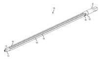
- FIG. 1is a perspective view of one aspect of an elongate dilator shaft for use with a dilator delivered nerve shield assembly;
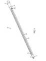
- FIG. 2is a side elevational view of the elongate dilator shaft of FIG. 1 ;
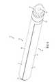
- FIG. 3is a perspective view of one aspect of an elongate nerve shield for use with a dilator delivered nerve shield assembly
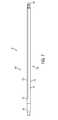
- FIG. 4is a perspective view of the elongate nerve shield of FIG. 3 , showing the elongate nerve shield's exterior surface;
- FIG. 5is an end elevational view of the elongate nerve shield of FIG. 3 ;
- FIG. 6is a perspective view of one aspect of a dilator delivered nerve shield assembly.
- FIG. 7is a side elevational view of the dilator delivered nerve shield assembly of FIG. 6 .
- shieldincludes aspects having two or more shields unless the context clearly indicates otherwise.
- Rangescan be expressed herein as from “about” one particular value, and/or to “about” another particular value. When such a range is expressed, another aspect includes from the one particular value and/or to the other particular value. Similarly, when values are expressed as approximations, by use of the antecedent “about,” it will be understood that the particular value forms another aspect. It will be further understood that the endpoints of each of the ranges are significant both in relation to the other endpoint, and independently of the other endpoint.
- the terms “optional” or “optionally”mean that the subsequently described event or circumstance may or may not occur, and that the description includes instances where said event or circumstance occurs and instances where it does not.
- the dilator delivered nerve shield assembly 10for use in spinal surgery.
- the dilator delivered nerve shield assembly 10comprises an elongate dilator shaft 100 with a distal end 110 and a proximal end 120 .
- the distal end 110 of the dilator elongate shaftis tapered to facilitate placing the elongate shaft percutaneously into the area of a desired motion segment.
- the dilator delivered nerve shield assemblyalso comprises an elongate nerve shield 200 that is configured for simultaneous insertion with the elongate dilator shaft 100 .
- the elongate dilator shaft and the elongate nerve shield 200engage one another to form the dilator delivered nerve shield assembly that is generally cylindrical in shape as a whole. It is contemplated that other shapes can also be utilized that may be substantially tubular with various cross sectional shapes, such as, but not limited round, elliptical, square, and the like.
- the elongate nerve shieldis an alternative to using a circumferential access portal/refractor for delivering an intervertebral interbody past the exiting nerve root. It achieves the result of shielding the exiting nerve root on one side of the implant path, without enlarging the path.
- the elongate dilator shafthas an exterior surface 130 and at least one engagement surface 140 .
- the elongate nerve shieldhas an interior surface 210 and an exterior surface 220 that is complimentary to the exterior surface 130 of the elongate dilator shaft 100 elongate surface, such that, when the elongate nerve shield is engaged with the elongate dilator shaft, the exterior surfaces of the combined elongate dilator shaft 100 and elongate nerve shield 200 define the peripheral surface 15 , forming the cross-sectional shape of the dilator delivered nerve shield assembly 10 . For instance, if the dilator delivered nerve shield assembly has a circular cross-sectional shape, the engaged combined elongate dilator shaft and elongate nerve shield comprise the circular shape.
- portions of the engagement surface 140 of the elongate dilator shaftare complimentarily longitudinally keyed to portions of the interior surface of the elongate nerve shield. In this manner, when engaged, the elongate nerve shield 200 can slide longitudinally with respect to the elongate dilator shaft 100 , but is retained from movement radially.
- the engagement surface of the elongate dilator shaftcomprises at least one longitudinal tongue 150 .
- the interior surface of the elongate nerve shielddefines at least one longitudinal groove 230 , where the groove and tongue are configured for a mating relationship. A plurality of tongues and complimentary grooves is also contemplated.
- the groovescan be angled with respect to one another to prevent radial movement of the elongate nerve shield with respect to the engaging surface.
- the elongate tonguecan comprise a keyed relationship with the elongate groove.
- the twocan have a dovetail shaped cross-section or a keystone shaped cross-section and the like. Other interlocking geometries that permit longitudinal movement while preventing radial movement are also contemplated.
- the elongate nerve shieldmay comprise the tongues, while the elongate shaft's engagement surface defines the grooves.
- the assemblycomprises a handle 20 connected to the proximal end 120 of the elongate dilator shaft.
- the handle and the elongate dilator shaft 100are integral.
- the proximal end of the elongate dilator shaftcan also comprise a stop 160 to keep an engaged elongate nerve shield 200 from moving proximally in the longitudinal direction.
- the assemblycan be positioned into the disc space between two adjacent vertebrae at the desired position and rotated to a point where the exterior surface 220 of the elongate nerve shield is adjacent the nerve root.
- the elongate dilator shaft 100may be removed, leaving the elongate nerve shield in position, shielding the nerve root from the operative field.
- the surgeoncan perform the necessary surgical procedure, such as, but not limited to, insertion of an inter-body cage without fear of damaging the nerve root.
- the elongate dilator shaftcan comprise an internal longitudinal passageway 170 .
- the systemcan be used to perform the surgical procedure over a guide wire.
- the proximal end of the handle of the systemmay also be sized and shaped to engage a rotation tool, such as a drill, or a larger handle.
- the elongate dilator shaftcan be conductive to allow for neurostimulation of the exiting nerve root.
- the elongate dilator shaftmay comprise stainless steel or aluminum and can be deanodized to be conductive.
- the elongate nerve shieldcan, in one aspect, comprise an insulating material.
- the elongate nerve shieldcan comprise medical grade polymer.
Landscapes
- Health & Medical Sciences (AREA)
- Life Sciences & Earth Sciences (AREA)
- Surgery (AREA)
- Public Health (AREA)
- Engineering & Computer Science (AREA)
- Biomedical Technology (AREA)
- Animal Behavior & Ethology (AREA)
- General Health & Medical Sciences (AREA)
- Veterinary Medicine (AREA)
- Heart & Thoracic Surgery (AREA)
- Nuclear Medicine, Radiotherapy & Molecular Imaging (AREA)
- Medical Informatics (AREA)
- Molecular Biology (AREA)
- Orthopedic Medicine & Surgery (AREA)
- Radiology & Medical Imaging (AREA)
- Physics & Mathematics (AREA)
- Optics & Photonics (AREA)
- Pathology (AREA)
- Biophysics (AREA)
- Anesthesiology (AREA)
- Hematology (AREA)
- Surgical Instruments (AREA)
- Neurology (AREA)
- Neurosurgery (AREA)
- Cardiology (AREA)
Abstract
Description
Claims (13)
Priority Applications (3)
| Application Number | Priority Date | Filing Date | Title |
|---|---|---|---|
| US14/059,318US9370348B2 (en) | 2012-10-23 | 2013-10-21 | Dilator delivered nerve shield |
| PCT/US2013/066077WO2014066322A1 (en) | 2012-10-23 | 2013-10-22 | Dilator delivered nerve shield |
| EP13848470.4AEP2911733B1 (en) | 2012-10-23 | 2013-10-22 | Dilator delivered nerve shield |
Applications Claiming Priority (2)
| Application Number | Priority Date | Filing Date | Title |
|---|---|---|---|
| US201261717579P | 2012-10-23 | 2012-10-23 | |
| US14/059,318US9370348B2 (en) | 2012-10-23 | 2013-10-21 | Dilator delivered nerve shield |
Publications (2)
| Publication Number | Publication Date |
|---|---|
| US20140114133A1 US20140114133A1 (en) | 2014-04-24 |
| US9370348B2true US9370348B2 (en) | 2016-06-21 |
Family
ID=50485932
Family Applications (1)
| Application Number | Title | Priority Date | Filing Date |
|---|---|---|---|
| US14/059,318Expired - Fee RelatedUS9370348B2 (en) | 2012-10-23 | 2013-10-21 | Dilator delivered nerve shield |
Country Status (3)
| Country | Link |
|---|---|
| US (1) | US9370348B2 (en) |
| EP (1) | EP2911733B1 (en) |
| WO (1) | WO2014066322A1 (en) |
Cited By (20)
| Publication number | Priority date | Publication date | Assignee | Title |
|---|---|---|---|---|
| US9724151B2 (en) | 2013-08-08 | 2017-08-08 | Relievant Medsystems, Inc. | Modulating nerves within bone using bone fasteners |
| US9775627B2 (en) | 2012-11-05 | 2017-10-03 | Relievant Medsystems, Inc. | Systems and methods for creating curved paths through bone and modulating nerves within the bone |
| US10028753B2 (en) | 2008-09-26 | 2018-07-24 | Relievant Medsystems, Inc. | Spine treatment kits |
| US10111704B2 (en) | 2002-09-30 | 2018-10-30 | Relievant Medsystems, Inc. | Intraosseous nerve treatment |
| US10265099B2 (en) | 2008-09-26 | 2019-04-23 | Relievant Medsystems, Inc. | Systems for accessing nerves within bone |
| US10390877B2 (en) | 2011-12-30 | 2019-08-27 | Relievant Medsystems, Inc. | Systems and methods for treating back pain |
| US10463423B2 (en) | 2003-03-28 | 2019-11-05 | Relievant Medsystems, Inc. | Thermal denervation devices and methods |
| US10588691B2 (en) | 2012-09-12 | 2020-03-17 | Relievant Medsystems, Inc. | Radiofrequency ablation of tissue within a vertebral body |
| USRE48460E1 (en) | 2002-09-30 | 2021-03-09 | Relievant Medsystems, Inc. | Method of treating an intraosseous nerve |
| US11007010B2 (en) | 2019-09-12 | 2021-05-18 | Relevant Medsysterns, Inc. | Curved bone access systems |
| US11305118B2 (en) | 2018-11-30 | 2022-04-19 | Biovisics Medical, Inc. | Head worn apparatuses for vision therapy |
| US11338139B2 (en) | 2018-10-01 | 2022-05-24 | Biovisics Medical, Inc. | System and methods for controlled electrical modulation for vision therapy |
| US11471680B2 (en) | 2019-04-10 | 2022-10-18 | Biovisics, Inc. | Systems and interfaces for ocular therapy |
| US11511112B2 (en) | 2019-06-14 | 2022-11-29 | Biovisics Medical, Inc. | Wearable medical device |
| US12023498B2 (en) | 2019-07-12 | 2024-07-02 | Biovisics Medical, Inc. | Ocular therapy modes and systems |
| US12039731B2 (en) | 2020-12-22 | 2024-07-16 | Relievant Medsystems, Inc. | Prediction of candidates for spinal neuromodulation |
| US12082876B1 (en) | 2020-09-28 | 2024-09-10 | Relievant Medsystems, Inc. | Introducer drill |
| US12102348B2 (en) | 2016-09-07 | 2024-10-01 | Vertos Medical, Inc. | Percutaneous lateral recess resection methods and instruments |
| US12324572B2 (en) | 2022-06-16 | 2025-06-10 | Vertos Medical, Inc. | Integrated instrument assembly |
| US12433668B1 (en) | 2021-11-08 | 2025-10-07 | Relievant Medsystems, Inc. | Impedance stoppage mitigation during radiofrequency tissue ablation procedures |
Families Citing this family (3)
| Publication number | Priority date | Publication date | Assignee | Title |
|---|---|---|---|---|
| US9662002B2 (en)* | 2014-07-10 | 2017-05-30 | Amendia, Inc. | Endoscopic portal protective shield assembly |
| US10136958B2 (en)* | 2014-10-28 | 2018-11-27 | Amendia, Inc. | Tissue protector and method of use |
| EP4223241B1 (en) | 2022-02-07 | 2025-08-20 | Hoogland Spine Products GmbH | Dilator for spinal surgery |
Citations (15)
| Publication number | Priority date | Publication date | Assignee | Title |
|---|---|---|---|---|
| US5759150A (en) | 1995-07-07 | 1998-06-02 | Olympus Optical Co., Ltd. | System for evulsing subcutaneous tissue |
| US6999819B2 (en)* | 2001-08-31 | 2006-02-14 | Medtronic, Inc. | Implantable medical electrical stimulation lead fixation method and apparatus |
| US20060217754A1 (en) | 2005-03-23 | 2006-09-28 | Boehm Frank H Jr | Expandable intervertebral disc dilating cannula |
| US7179225B2 (en)* | 2003-08-26 | 2007-02-20 | Shluzas Alan E | Access systems and methods for minimally invasive surgery |
| US7226451B2 (en)* | 2003-08-26 | 2007-06-05 | Shluzas Alan E | Minimally invasive access device and method |
| US7485092B1 (en) | 1998-08-12 | 2009-02-03 | Maquet Cardiovascular Llc | Vessel harvesting apparatus and method |
| US20100010334A1 (en) | 2005-05-16 | 2010-01-14 | Bleich Jeffery L | Spinal access and neural localization |
| US20100145267A1 (en) | 2008-11-10 | 2010-06-10 | Onset Medical Corporation | Expandable spinal sheath and method of use |
| US7744612B2 (en)* | 2004-02-10 | 2010-06-29 | Spinal Elements, Inc. | System and method for protecting neurovascular structures |
| US20100331780A1 (en)* | 2009-06-26 | 2010-12-30 | Tyco Healthcare Group Lp | Catheterization System |
| US7909832B2 (en) | 2001-03-01 | 2011-03-22 | Warsaw Orthopedic, Inc. | Retractor for percutaneous surgery in a patient and method for use thereof |
| US20110208226A1 (en) | 2007-10-05 | 2011-08-25 | Fatone Peter | Dilation system and method of using the same |
| US20110301631A1 (en) | 2001-09-25 | 2011-12-08 | James Gharib | Systems and Methods for Performing Surgical Procedures and Assessments |
| US20110313286A1 (en) | 2010-05-13 | 2011-12-22 | Ncontact Surgical, Inc. | Subxyphoid epicardial ablation |
| US8394129B2 (en)* | 2011-03-10 | 2013-03-12 | Interventional Spine, Inc. | Method and apparatus for minimally invasive insertion of intervertebral implants |
Family Cites Families (4)
| Publication number | Priority date | Publication date | Assignee | Title |
|---|---|---|---|---|
| US8617062B2 (en)* | 2010-07-08 | 2013-12-31 | Warsaw Orthopedic, Inc. | Over dilation |
| US20120022575A1 (en)* | 2010-07-26 | 2012-01-26 | Warsaw Orthopedic, Inc. An Indiana Corporation | Laterally expanding surgical dilator |
| US8702600B2 (en)* | 2011-03-08 | 2014-04-22 | Pioneer Surgical Technology, Inc. | Apparatus and method for enlarging an incision |
| US8518087B2 (en)* | 2011-03-10 | 2013-08-27 | Interventional Spine, Inc. | Method and apparatus for minimally invasive insertion of intervertebral implants |
- 2013
- 2013-10-21USUS14/059,318patent/US9370348B2/ennot_activeExpired - Fee Related
- 2013-10-22EPEP13848470.4Apatent/EP2911733B1/ennot_activeNot-in-force
- 2013-10-22WOPCT/US2013/066077patent/WO2014066322A1/enactiveApplication Filing
Patent Citations (15)
| Publication number | Priority date | Publication date | Assignee | Title |
|---|---|---|---|---|
| US5759150A (en) | 1995-07-07 | 1998-06-02 | Olympus Optical Co., Ltd. | System for evulsing subcutaneous tissue |
| US7485092B1 (en) | 1998-08-12 | 2009-02-03 | Maquet Cardiovascular Llc | Vessel harvesting apparatus and method |
| US7909832B2 (en) | 2001-03-01 | 2011-03-22 | Warsaw Orthopedic, Inc. | Retractor for percutaneous surgery in a patient and method for use thereof |
| US6999819B2 (en)* | 2001-08-31 | 2006-02-14 | Medtronic, Inc. | Implantable medical electrical stimulation lead fixation method and apparatus |
| US20110301631A1 (en) | 2001-09-25 | 2011-12-08 | James Gharib | Systems and Methods for Performing Surgical Procedures and Assessments |
| US7179225B2 (en)* | 2003-08-26 | 2007-02-20 | Shluzas Alan E | Access systems and methods for minimally invasive surgery |
| US7226451B2 (en)* | 2003-08-26 | 2007-06-05 | Shluzas Alan E | Minimally invasive access device and method |
| US7744612B2 (en)* | 2004-02-10 | 2010-06-29 | Spinal Elements, Inc. | System and method for protecting neurovascular structures |
| US20060217754A1 (en) | 2005-03-23 | 2006-09-28 | Boehm Frank H Jr | Expandable intervertebral disc dilating cannula |
| US20100010334A1 (en) | 2005-05-16 | 2010-01-14 | Bleich Jeffery L | Spinal access and neural localization |
| US20110208226A1 (en) | 2007-10-05 | 2011-08-25 | Fatone Peter | Dilation system and method of using the same |
| US20100145267A1 (en) | 2008-11-10 | 2010-06-10 | Onset Medical Corporation | Expandable spinal sheath and method of use |
| US20100331780A1 (en)* | 2009-06-26 | 2010-12-30 | Tyco Healthcare Group Lp | Catheterization System |
| US20110313286A1 (en) | 2010-05-13 | 2011-12-22 | Ncontact Surgical, Inc. | Subxyphoid epicardial ablation |
| US8394129B2 (en)* | 2011-03-10 | 2013-03-12 | Interventional Spine, Inc. | Method and apparatus for minimally invasive insertion of intervertebral implants |
Cited By (47)
| Publication number | Priority date | Publication date | Assignee | Title |
|---|---|---|---|---|
| US11596468B2 (en) | 2002-09-30 | 2023-03-07 | Relievant Medsystems, Inc. | Intraosseous nerve treatment |
| USRE48460E1 (en) | 2002-09-30 | 2021-03-09 | Relievant Medsystems, Inc. | Method of treating an intraosseous nerve |
| US10111704B2 (en) | 2002-09-30 | 2018-10-30 | Relievant Medsystems, Inc. | Intraosseous nerve treatment |
| US10478246B2 (en) | 2002-09-30 | 2019-11-19 | Relievant Medsystems, Inc. | Ablation of tissue within vertebral body involving internal cooling |
| US10463423B2 (en) | 2003-03-28 | 2019-11-05 | Relievant Medsystems, Inc. | Thermal denervation devices and methods |
| US10265099B2 (en) | 2008-09-26 | 2019-04-23 | Relievant Medsystems, Inc. | Systems for accessing nerves within bone |
| US10905440B2 (en) | 2008-09-26 | 2021-02-02 | Relievant Medsystems, Inc. | Nerve modulation systems |
| US12161350B2 (en) | 2008-09-26 | 2024-12-10 | Relievant Medsystems, Inc. | Systems for treating nerves within bone using steam |
| US12303166B2 (en) | 2008-09-26 | 2025-05-20 | Relievant Medsystems, Inc. | Methods for accessing nerves within bone |
| US11471171B2 (en) | 2008-09-26 | 2022-10-18 | Relievant Medsystems, Inc. | Bipolar radiofrequency ablation systems for treatment within bone |
| US12329412B2 (en) | 2008-09-26 | 2025-06-17 | Relievant Medsystems, Inc. | Systems for accessing nerves within bone |
| US10028753B2 (en) | 2008-09-26 | 2018-07-24 | Relievant Medsystems, Inc. | Spine treatment kits |
| US11471210B2 (en) | 2011-12-30 | 2022-10-18 | Relievant Medsystems, Inc. | Methods of denervating vertebral body using external energy source |
| US12059193B2 (en) | 2011-12-30 | 2024-08-13 | Relievant Medsystems, Inc. | Methods of denervating vertebral body using external energy source |
| US10390877B2 (en) | 2011-12-30 | 2019-08-27 | Relievant Medsystems, Inc. | Systems and methods for treating back pain |
| US10588691B2 (en) | 2012-09-12 | 2020-03-17 | Relievant Medsystems, Inc. | Radiofrequency ablation of tissue within a vertebral body |
| US11737814B2 (en) | 2012-09-12 | 2023-08-29 | Relievant Medsystems, Inc. | Cryotherapy treatment for back pain |
| US11701168B2 (en) | 2012-09-12 | 2023-07-18 | Relievant Medsystems, Inc. | Radiofrequency ablation of tissue within a vertebral body |
| US11690667B2 (en) | 2012-09-12 | 2023-07-04 | Relievant Medsystems, Inc. | Radiofrequency ablation of tissue within a vertebral body |
| US11974759B2 (en) | 2012-11-05 | 2024-05-07 | Relievant Medsystems, Inc. | Methods of navigation and treatment within a vertebral body |
| US11160563B2 (en) | 2012-11-05 | 2021-11-02 | Relievant Medsystems, Inc. | Systems for navigation and treatment within a vertebral body |
| US11291502B2 (en) | 2012-11-05 | 2022-04-05 | Relievant Medsystems, Inc. | Methods of navigation and treatment within a vertebral body |
| US10517611B2 (en) | 2012-11-05 | 2019-12-31 | Relievant Medsystems, Inc. | Systems for navigation and treatment within a vertebral body |
| US10357258B2 (en) | 2012-11-05 | 2019-07-23 | Relievant Medsystems, Inc. | Systems and methods for creating curved paths through bone |
| US11234764B1 (en) | 2012-11-05 | 2022-02-01 | Relievant Medsystems, Inc. | Systems for navigation and treatment within a vertebral body |
| US9775627B2 (en) | 2012-11-05 | 2017-10-03 | Relievant Medsystems, Inc. | Systems and methods for creating curved paths through bone and modulating nerves within the bone |
| US12193719B2 (en) | 2013-08-08 | 2025-01-14 | Relievant Medsystems, Inc. | Modulating nerves within bone |
| US10456187B2 (en) | 2013-08-08 | 2019-10-29 | Relievant Medsystems, Inc. | Modulating nerves within bone using bone fasteners |
| US11065046B2 (en) | 2013-08-08 | 2021-07-20 | Relievant Medsystems, Inc. | Modulating nerves within bone |
| US9724151B2 (en) | 2013-08-08 | 2017-08-08 | Relievant Medsystems, Inc. | Modulating nerves within bone using bone fasteners |
| US12102348B2 (en) | 2016-09-07 | 2024-10-01 | Vertos Medical, Inc. | Percutaneous lateral recess resection methods and instruments |
| US12420097B2 (en) | 2018-10-01 | 2025-09-23 | I-Lumen Scientific, Inc. | System and methods for controlled electrical modulation for vision therapy |
| US11338139B2 (en) | 2018-10-01 | 2022-05-24 | Biovisics Medical, Inc. | System and methods for controlled electrical modulation for vision therapy |
| US11305118B2 (en) | 2018-11-30 | 2022-04-19 | Biovisics Medical, Inc. | Head worn apparatuses for vision therapy |
| US11471680B2 (en) | 2019-04-10 | 2022-10-18 | Biovisics, Inc. | Systems and interfaces for ocular therapy |
| US11511112B2 (en) | 2019-06-14 | 2022-11-29 | Biovisics Medical, Inc. | Wearable medical device |
| US12023498B2 (en) | 2019-07-12 | 2024-07-02 | Biovisics Medical, Inc. | Ocular therapy modes and systems |
| US11007010B2 (en) | 2019-09-12 | 2021-05-18 | Relevant Medsysterns, Inc. | Curved bone access systems |
| US11123103B2 (en) | 2019-09-12 | 2021-09-21 | Relievant Medsystems, Inc. | Introducer systems for bone access |
| US11202655B2 (en) | 2019-09-12 | 2021-12-21 | Relievant Medsystems, Inc. | Accessing and treating tissue within a vertebral body |
| US11207100B2 (en) | 2019-09-12 | 2021-12-28 | Relievant Medsystems, Inc. | Methods of detecting and treating back pain |
| US11426199B2 (en) | 2019-09-12 | 2022-08-30 | Relievant Medsystems, Inc. | Methods of treating a vertebral body |
| US12082876B1 (en) | 2020-09-28 | 2024-09-10 | Relievant Medsystems, Inc. | Introducer drill |
| US12039731B2 (en) | 2020-12-22 | 2024-07-16 | Relievant Medsystems, Inc. | Prediction of candidates for spinal neuromodulation |
| US12433668B1 (en) | 2021-11-08 | 2025-10-07 | Relievant Medsystems, Inc. | Impedance stoppage mitigation during radiofrequency tissue ablation procedures |
| US12324572B2 (en) | 2022-06-16 | 2025-06-10 | Vertos Medical, Inc. | Integrated instrument assembly |
| US12342999B2 (en) | 2022-06-16 | 2025-07-01 | Vertos Medical, Inc. | Integrated instrument assembly |
Also Published As
| Publication number | Publication date |
|---|---|
| US20140114133A1 (en) | 2014-04-24 |
| WO2014066322A1 (en) | 2014-05-01 |
| EP2911733A1 (en) | 2015-09-02 |
| EP2911733A4 (en) | 2016-07-13 |
| EP2911733B1 (en) | 2019-07-31 |
Similar Documents
| Publication | Publication Date | Title |
|---|---|---|
| US9370348B2 (en) | Dilator delivered nerve shield | |
| US9241722B2 (en) | Surgical pin guide and methods of use | |
| US20070066977A1 (en) | Exchange system for axial spinal procedures | |
| US9055936B2 (en) | Over dilation | |
| US8834507B2 (en) | Dilation instruments and methods | |
| US9480520B2 (en) | Surgical instrument and method | |
| US20130103103A1 (en) | Surgical system methods for spinal access | |
| US12207826B2 (en) | Combined bone tap and rasp | |
| Kim et al. | Analysis of clinical results of three different routes of percutaneous endoscopic transforaminal lumbar discectomy for lumbar herniated disk | |
| US10639057B2 (en) | Multi-tine cutting device | |
| Mobbs et al. | Outcomes of percutaneous pedicle screw fixation for spinal trauma and tumours | |
| Passacantilli et al. | Endoscopic interlaminar approach for intracanal L 5‐S 1 disc herniation: Classification of disc prolapse in relation to learning curve and surgical outcome | |
| Li et al. | Percutaneous isthmus Foraminoplasty and full-endoscopic lumbar discectomy for very highly Upmigrated lumbar disc herniation: technique notes and 2 years follow-up | |
| JP2025504010A (en) | Spinal surgery dilator | |
| Telfeian | Transforaminal endoscopic solution to disk reherniation post-mini-TLIF: case report | |
| JP7546928B2 (en) | Medical Delivery Devices | |
| Yao et al. | Percutaneous endoscopic transforaminal decompression in the treatment of patients with migrated lumbar disc herniation: a retrospective study | |
| US20170020404A1 (en) | Neuromonitoring probe systems and methods | |
| Delgado-López et al. | Total en bloc spondylectomy for spinal tumours: technical aspects and surgical details | |
| Zhou et al. | Original Designed Uniportal‐Bichannel Spinal Endoscopic System (UBiSES) for Foraminoplasty in Percutaneous Endoscopic Transforaminal Discectomy | |
| US11648052B2 (en) | Method and apparatus for treating lumbar pain | |
| DE102010051282A1 (en) | Micro-surgical, diamond-coated machining head for use in e.g. cutting tool, for surgical treatment of spinal channel stenosis in e.g. humans, has side surfaces contacting one another through large diameters along edge formed by surfaces |
Legal Events
| Date | Code | Title | Description |
|---|---|---|---|
| AS | Assignment | Owner name:AMENDIA, INC., GEORGIA Free format text:ASSIGNMENT OF ASSIGNORS INTEREST;ASSIGNOR:TALLY, WILLIAM;REEL/FRAME:033553/0166 Effective date:20140105 | |
| AS | Assignment | Owner name:SILICON VALLEY BANK, AS ADMINISTRATIVE AGENT, GEOR Free format text:PATENT SECURITY AGREEMENT;ASSIGNORS:AMENDIA, INC.;OMNI ACQUISITION, INC.;REEL/FRAME:033696/0940 Effective date:20140905 | |
| AS | Assignment | Owner name:AMENDIA, INC., GEORGIA Free format text:CORRECTIVE ASSIGNMENT TO CORRECT ADD SECOND ASSIGNOR PREVIOUSLY RECORDED AT REEL: 033553 FRAME: 0166. ASSIGNOR(S) HEREBY CONFIRMS THE ASSIGNMENT;ASSIGNORS:TALLY, WILLIAM;BARRA, KENNETH;REEL/FRAME:035011/0293 Effective date:20140105 | |
| AS | Assignment | Owner name:AMENDIA, INC., GEORGIA Free format text:RELEASE BY SECURED PARTY;ASSIGNOR:SILICON VALLEY BANK, AS ADMINISTRATIVE AGENT;REEL/FRAME:038578/0828 Effective date:20160429 Owner name:OMNI ACQUISITION INC., GEORGIA Free format text:RELEASE BY SECURED PARTY;ASSIGNOR:SILICON VALLEY BANK, AS ADMINISTRATIVE AGENT;REEL/FRAME:038578/0828 Effective date:20160429 | |
| AS | Assignment | Owner name:ANTARES CAPITAL LP, AS AGENT, ILLINOIS Free format text:SECURITY INTEREST;ASSIGNOR:AMENDIA, INC.;REEL/FRAME:038587/0753 Effective date:20160429 | |
| AS | Assignment | Owner name:CORTLAND CAPITAL MARKET SERVICES LLC, AS AGENT, IL Free format text:SECURITY INTEREST;ASSIGNOR:AMENDIA, INC.;REEL/FRAME:038606/0520 Effective date:20160429 | |
| ZAAA | Notice of allowance and fees due | Free format text:ORIGINAL CODE: NOA | |
| ZAAB | Notice of allowance mailed | Free format text:ORIGINAL CODE: MN/=. | |
| STCF | Information on status: patent grant | Free format text:PATENTED CASE | |
| FEPP | Fee payment procedure | Free format text:MAINTENANCE FEE REMINDER MAILED (ORIGINAL EVENT CODE: REM.); ENTITY STATUS OF PATENT OWNER: SMALL ENTITY | |
| AS | Assignment | Owner name:SPINAL ELEMENTS, INC., CALIFORNIA Free format text:MERGER AND CHANGE OF NAME;ASSIGNORS:SPINAL ELEMENTS, INC.;AMENDIA, INC.;REEL/FRAME:052024/0805 Effective date:20191231 | |
| FEPP | Fee payment procedure | Free format text:SURCHARGE FOR LATE PAYMENT, SMALL ENTITY (ORIGINAL EVENT CODE: M2554); ENTITY STATUS OF PATENT OWNER: SMALL ENTITY | |
| MAFP | Maintenance fee payment | Free format text:PAYMENT OF MAINTENANCE FEE, 4TH YR, SMALL ENTITY (ORIGINAL EVENT CODE: M2551); ENTITY STATUS OF PATENT OWNER: SMALL ENTITY Year of fee payment:4 | |
| FEPP | Fee payment procedure | Free format text:MAINTENANCE FEE REMINDER MAILED (ORIGINAL EVENT CODE: REM.); ENTITY STATUS OF PATENT OWNER: SMALL ENTITY | |
| AS | Assignment | Owner name:PERCEPTIVE CREDIT HOLDINGS IV, LP, NEW YORK Free format text:SECURITY INTEREST;ASSIGNORS:SPINAL ELEMENTS, INC.;CUSTOM SPINE ACQUISITION, INC.;OMNI ACQUISITION INC.;REEL/FRAME:067596/0295 Effective date:20240531 | |
| AS | Assignment | Owner name:SPINAL ELEMENTS, INC. (F.K.A. AMENDIA, INC.), CALIFORNIA Free format text:RELEASE BY SECURED PARTY;ASSIGNOR:CORTLAND CAPITAL MARKET SERVICES LLC, AS AGENT;REEL/FRAME:067605/0676 Effective date:20240531 Owner name:SPINAL ELEMENTS, INC. (F.K.A. AMENDIA, INC.), CALIFORNIA Free format text:RELEASE BY SECURED PARTY;ASSIGNOR:ANTARES CAPITAL LP, AS ADMINISTRATIVE AGENT;REEL/FRAME:067605/0599 Effective date:20240531 | |
| LAPS | Lapse for failure to pay maintenance fees | Free format text:PATENT EXPIRED FOR FAILURE TO PAY MAINTENANCE FEES (ORIGINAL EVENT CODE: EXP.); ENTITY STATUS OF PATENT OWNER: SMALL ENTITY | |
| STCH | Information on status: patent discontinuation | Free format text:PATENT EXPIRED DUE TO NONPAYMENT OF MAINTENANCE FEES UNDER 37 CFR 1.362 | |
| FP | Lapsed due to failure to pay maintenance fee | Effective date:20240621 |