US9366756B2 - RF tag reader for accurate position determination - Google Patents
RF tag reader for accurate position determinationDownload PDFInfo
- Publication number
- US9366756B2 US9366756B2US12/329,564US32956408AUS9366756B2US 9366756 B2US9366756 B2US 9366756B2US 32956408 AUS32956408 AUS 32956408AUS 9366756 B2US9366756 B2US 9366756B2
- Authority
- US
- United States
- Prior art keywords
- signal
- antenna
- difference
- component
- antennas
- Prior art date
- Legal status (The legal status is an assumption and is not a legal conclusion. Google has not performed a legal analysis and makes no representation as to the accuracy of the status listed.)
- Active, expires
Links
- 238000001514detection methodMethods0.000claimsabstractdescription18
- 238000000034methodMethods0.000claimsabstractdescription5
- 230000004044responseEffects0.000claimsdescription17
- 230000007704transitionEffects0.000claimsdescription5
- 230000005540biological transmissionEffects0.000claimsdescription3
- 238000010586diagramMethods0.000description6
- 238000000926separation methodMethods0.000description4
- 230000001427coherent effectEffects0.000description3
- RTZKZFJDLAIYFH-UHFFFAOYSA-NDiethyl etherChemical compoundCCOCCRTZKZFJDLAIYFH-UHFFFAOYSA-N0.000description2
- 238000003491arrayMethods0.000description2
- 230000008901benefitEffects0.000description2
- 238000004891communicationMethods0.000description2
- 230000007246mechanismEffects0.000description2
- 230000003068static effectEffects0.000description2
- 239000000654additiveSubstances0.000description1
- 230000000996additive effectEffects0.000description1
- 230000005684electric fieldEffects0.000description1
- 230000003993interactionEffects0.000description1
- 230000003287optical effectEffects0.000description1
- 230000010287polarizationEffects0.000description1
- 230000008569processEffects0.000description1
- 238000006467substitution reactionMethods0.000description1
Images


Classifications
- G—PHYSICS
- G01—MEASURING; TESTING
- G01S—RADIO DIRECTION-FINDING; RADIO NAVIGATION; DETERMINING DISTANCE OR VELOCITY BY USE OF RADIO WAVES; LOCATING OR PRESENCE-DETECTING BY USE OF THE REFLECTION OR RERADIATION OF RADIO WAVES; ANALOGOUS ARRANGEMENTS USING OTHER WAVES
- G01S13/00—Systems using the reflection or reradiation of radio waves, e.g. radar systems; Analogous systems using reflection or reradiation of waves whose nature or wavelength is irrelevant or unspecified
- G01S13/02—Systems using reflection of radio waves, e.g. primary radar systems; Analogous systems
- G01S13/06—Systems determining position data of a target
- G01S13/42—Simultaneous measurement of distance and other co-ordinates
- G01S13/44—Monopulse radar, i.e. simultaneous lobing
- G01S13/4454—Monopulse radar, i.e. simultaneous lobing phase comparisons monopulse, i.e. comparing the echo signals received by an interferometric antenna arrangement
- B—PERFORMING OPERATIONS; TRANSPORTING
- B61—RAILWAYS
- B61L—GUIDING RAILWAY TRAFFIC; ENSURING THE SAFETY OF RAILWAY TRAFFIC
- B61L25/00—Recording or indicating positions or identities of vehicles or trains or setting of track apparatus
- B61L25/02—Indicating or recording positions or identities of vehicles or trains
- B61L25/025—Absolute localisation, e.g. providing geodetic coordinates
- G—PHYSICS
- G01—MEASURING; TESTING
- G01S—RADIO DIRECTION-FINDING; RADIO NAVIGATION; DETERMINING DISTANCE OR VELOCITY BY USE OF RADIO WAVES; LOCATING OR PRESENCE-DETECTING BY USE OF THE REFLECTION OR RERADIATION OF RADIO WAVES; ANALOGOUS ARRANGEMENTS USING OTHER WAVES
- G01S13/00—Systems using the reflection or reradiation of radio waves, e.g. radar systems; Analogous systems using reflection or reradiation of waves whose nature or wavelength is irrelevant or unspecified
- G01S13/74—Systems using reradiation of radio waves, e.g. secondary radar systems; Analogous systems
- G01S13/76—Systems using reradiation of radio waves, e.g. secondary radar systems; Analogous systems wherein pulse-type signals are transmitted
- G01S13/762—Systems using reradiation of radio waves, e.g. secondary radar systems; Analogous systems wherein pulse-type signals are transmitted with special measures concerning the radiation pattern, e.g. S.L.S.
Definitions
- the position of a radio frequency (RF) tag as read by a tag interrogatormay be anywhere within the footprint of the interrogator read antenna.
- the footprint widthis wider than the desired position accuracy for determining the position of the RF tag with respect to the tag interrogator.
- Prior solutions of which the inventor is awareemploy a tag interrogator with read footprints of up to 1 meter or more in width. Further, signal processing may be used to estimate the location of the RF tag based on the received signal shape. RF tag position uncertainty, along with other data input, leads to the calculation of a safety distance in front of a vehicle having the tag interrogator in order to maintain a safe separation distance. As the position uncertainty increases so too does the safety separation distance with the result of requiring a larger separation distance than if the position were known. A larger separation distance results in lower vehicle throughput and ultimately less revenue, if applicable, for a vehicle operator.
- FIG. 1is a high-level functional block diagram of a system comprising an embodiment of a position determination system
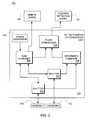
- FIG. 2is a high-level functional block diagram of a computer system usable in conjunction with an embodiment
- FIG. 3is a high-level functional block diagram of a detail view of a position determination system according to another embodiment.
- FIG. 4is a graph of signal strength according to an embodiment.
- FIG. 1depicts a high-level functional block diagram of a system 100 in conjunction with which an embodiment of a position determination system 102 according to an embodiment may be used to great advantage.
- System 100is an exemplary system depicting a vehicle 104 , e.g. a railroad car, adjacent a travel surface 106 , e.g., a rail.
- vehicle 104e.g. a railroad car
- travel surface 106e.g., a rail.
- FIG. 1depicts a side view of vehicle 104 above travel surface 106 .
- vehicle 104comprises position determination system 102 and travels in a direction A along travel surface 106 .
- Vehicle 104passes by a radio frequency (RF) tag 108 , e.g., a radio frequency identification (RFID) tag.
- RFIDradio frequency identification
- tag 108comprises an RF tag configured to provide a reflection or transponding capability at the RF frequency used.
- RF tag 108is affixed to and/or embedded within another item.
- RF tag 108may be a passive and/or active device.
- Vehicle 104comprises a pair of antennas (“antenna 1 ” and “antenna 2 ”) 110 , 112 , which form a part of position determination system 102 , linearly spaced apart from each other along a surface of vehicle 104 .
- antennas 110 , 112are positioned to pass by RF tag 108 in a serial manner at a distance parallel to the RF tag.
- Each antenna 110 , 112is combined to form an antenna array which is arranged to generate a signal over a corresponding predetermined footprint, i.e. antenna beam width, referred to as antenna footprint 114 (as indicated by a chained, double-dotted line) and antenna footprint 116 (as indicated by a chained, single-dotted line), respectively within a respective footprints 114 , 116 .
- the two footprintsresult from the antennas combined in a phase coherent way to form sum or difference antenna patterns, i.e., the antennas are used as a phased antenna array.
- each antennatransmits a signal and receives a reply from RF tag 108 as schematically depicted by signals 120 , 122 , respectively.
- the antennastransmit one signal as a sum array, and receive a signal as both a sum and a difference array.
- each antenna 110 , 112generates an electromagnetic signal.
- the antenna footprintmay be on the order of 0.5 meter (m) to 1.5 m in width.
- more than two antennasmay be used to form the antenna array.
- a single phased array antennamay be used in place of individual antennas 110 , 112 .
- each antenna array 110 , 112is arranged to transmit an interrogation signal to RF tag 108 . Responsive to receipt of the interrogation signal from an antenna array, either antenna 110 or antenna 112 , RF tag 108 transmits a response signal.
- the response signalmay be a reflection signal or a transponder signal.
- Position determination system 102comprises antennas arrays 110 , 112 communicatively coupled with an RF tag position determination unit 124 . In at least some embodiments, position determination system 102 is directly electrically coupled with antennas 110 , 112 . Position determination unit 124 is communicatively coupled with a main RF signal output 126 and a position detection signal output 128 . In at least some embodiments, position determination system 102 is directly electrically coupled with main RF signal output 126 and position detection signal output 128 .
- one or more elements of position determination system 102may be positioned interior and/or exterior to vehicle 104 .
- each element of position determination system 102is positioned exterior to vehicle 104 ; while in other embodiments, each element of the position determination system is positioned interior to the vehicle.
- the spacing and orientation of the antennasvary depending on the array patterns that are to be achieved.
- the antenna arrayis implemented within one physical antenna package with separate elements representing each antenna.
- the polarization of the antenna arrays and tag 108i.e. the direction of the electric field vector
- transmission of the interrogation signalmay be performed by either antenna, or by both antennas configured as a sum array.
- FIG. 2depicts a high-level functional block diagram of a computer system 200 usable in conjunction with an embodiment.
- Computer system 200comprises a processor 202 (alternatively referred to as a processing device), an input/output (I/O) device 204 , a memory 206 , detection I/O device 208 communicatively coupled via a bus 210 or other interconnection communication mechanism. Additionally, computer system 200 comprises connections to antennas 110 , 112 via detection I/O 208 , i.e., circuitry output arranged to process and convert the analogue RF signals to digital detection signals), e.g. via bus 210 .
- Detection I/O device 208comprises position determination unit (PDU) 124 , main RF signal output 126 , and position detection signal output 128 .
- processor 202may be a controller and/or and application-specific integrated circuit (ASIC) configured to execute a set of instructions such as those embodied by an embodiment.
- ASICapplication-specific integrated circuit
- Memory 206may comprise a random access memory (RAM) or other dynamic storage device, coupled to the bus 210 for storing data and/or instructions to be executed by processor 202 , e.g., a position determination functionality 212 .
- RAMrandom access memory
- Memory 206also may be used for storing temporary variables or other intermediate information during execution of instructions to be executed by processor 202 .
- Memory 206may also comprise a read only memory (ROM) or other static storage device coupled to the bus 210 for storing static information and instructions for the processor 202 .
- ROMread only memory
- a storage devicesuch as a magnetic disk, optical disk, or electromagnetic disk, may also be provided and coupled to the bus 210 for storing data and/or instructions.
- Position determination functionality 212comprises a set of circuitry arranged to determine the position of RF tag 108 with respect to antennas 110 , 112 .
- position determination functionality 212comprises a set of executable instructions which, when executed by processor 202 , cause the processor to provide position determining functionality according to an embodiment.
- I/O device 204may comprise an input device, an output device and/or a combined input/output device for enabling user interaction.
- An input devicemay comprise, for example, a keyboard, keypad, mouse, trackball, trackpad, and/or cursor direction keys for communicating information and commands to processor 202 .
- An output devicemay comprise, for example, a display, a printer, a voice synthesizer, etc. for communicating information to a user.
- I/O device 204may comprise a serial and/or parallel connection mechanism for enabling the transfer of one or more of files and/or commands, e.g., an Ethernet or other type network connection.
- the positioning systeminterfaces directly to an on-board control system, e.g., an on-board train control processor, through an Ethernet communication protocol or one of several serial interface protocols.
- an on-board control systeme.g., an on-board train control processor
- FIG. 3depicts a high-level functional block diagram of a least a portion of position determination system 102 .
- FIG. 3depicts a detailed view of tag position determination unit 124 according to an embodiment.
- Position determination unit 124comprises a first RF splitter component 300 and a second RF splitter component 302 each receiving a single input signal from antennas 110 , 112 , respectively. That is, splitter component 300 receives a signal input from antenna 110 and splitter component 302 receives a signal input from antenna 112 .
- the signal input received by antennas 110 , 112is the response signal transmitted by RF tag 108 and received by antennas 110 , 112 .
- RF splitter components 300 , 302may comprise an integrated component of the antenna array, e.g., splitter 300 may comprise a portion of antenna 110 .
- Splitter component 300transmits the received response signal from antenna 110 to a sum combiner component 304 and a difference combiner component 306 .
- splitter component 300transmits the received response signal to sum combiner component 304 and difference combiner component 306 at the same time.
- splitter component 302transmits the received response signal from antenna 112 to sum combiner component 304 and difference combiner component 306 .
- Sum combiner component 304combines, in an phase coherent additive fashion, the received response signals from antenna 110 and antenna 112 and transmit the resulting signal to main RF signal output 126 and phase comparison component 308 (also referred to as a phase comparator).
- Difference combiner component 306generates a phase coherent difference signal corresponding to the difference between the received response signal from antenna 110 and antenna 112 and transmits the resulting difference signal to phase comparison component 308 .
- a single antenna devicee.g., antennas 110 , 112 in a single combined unit, may comprise the functionality of splitter components 300 , 302 , sum combiner component 304 , and difference combiner component 306 .
- Phase comparison component 308compares the phase difference between the generated sum signal received from sum component 304 and the generated difference signal received from different component 306 . Phase comparison component 308 transmits the resulting signal to position detection signal output 128 .
- Position detection signal output 128indicates that position determination system 102 , specifically antennas 110 , 112 , are positioned over RF tag 108 at the time the generated resulting phase difference signal transitions from 0° (degrees) to 180° (degrees). That is, antennas 110 , 112 are positioned on either side of RF tag 108 and/or RF tag 108 is positioned equally distant between antennas 110 , 112 . In at least some embodiments, the determination of a phase difference transition is performed based on a predetermined distance from 180 degrees phase difference.
- main RF signal output 126is used for identification of RF tag 108 and position detection signal output 128 is used to identify passage of the center point between antennas 110 , 112 over the RF tag.
- FIG. 3also depicts a signal generator 310 comprising a portion of position determination unit 124 and arranged to generate an interrogation signal for transmission to tag 108 .
- the generated interrogation signal from signal generator 310is provided to sum combiner component 304 which splits the received interrogation signal into two signals, one each sent to an antenna 110 , 112 .
- Antennas 110 , 112transmit the received detection signal as a phased signal toward tag 108 .
- signal generator 310may comprise a component separate from position determination unit 124 . Further, in some embodiments, signal generator 310 may comprise more than one signal generator for generating the interrogation signal to be transmitted by antennas 110 , 112 .
- FIG. 4depicts a graph of signal strength of the generated sum signal and difference signal from sum component 304 and difference component 306 , respectively.
- FIG. 4depicts the signal received from a transponding or reflecting tag by two closely spaced antennas in sum and difference combinations as the antennas move linearly past the tag.
- FIG. 4depicts the determined phase difference between the sum signal and the difference signal.
- the vertical axis to the left of the graph of FIG. 4indicates the relative signal strength of the sum signal and the difference signal.
- the vertical access to the right of the graphindicates the phase difference between the sum signal and the difference signal.
- the horizontal axisrepresents the distance with respect to the center point.
Landscapes
- Engineering & Computer Science (AREA)
- Radar, Positioning & Navigation (AREA)
- Remote Sensing (AREA)
- Computer Networks & Wireless Communication (AREA)
- Physics & Mathematics (AREA)
- General Physics & Mathematics (AREA)
- Mechanical Engineering (AREA)
- Radar Systems Or Details Thereof (AREA)
Abstract
Description
Claims (6)
Priority Applications (1)
| Application Number | Priority Date | Filing Date | Title |
|---|---|---|---|
| US12/329,564US9366756B2 (en) | 2008-12-06 | 2008-12-06 | RF tag reader for accurate position determination |
Applications Claiming Priority (1)
| Application Number | Priority Date | Filing Date | Title |
|---|---|---|---|
| US12/329,564US9366756B2 (en) | 2008-12-06 | 2008-12-06 | RF tag reader for accurate position determination |
Publications (2)
| Publication Number | Publication Date |
|---|---|
| US20100141454A1 US20100141454A1 (en) | 2010-06-10 |
| US9366756B2true US9366756B2 (en) | 2016-06-14 |
Family
ID=42230450
Family Applications (1)
| Application Number | Title | Priority Date | Filing Date |
|---|---|---|---|
| US12/329,564Active2034-09-12US9366756B2 (en) | 2008-12-06 | 2008-12-06 | RF tag reader for accurate position determination |
Country Status (1)
| Country | Link |
|---|---|
| US (1) | US9366756B2 (en) |
Families Citing this family (9)
| Publication number | Priority date | Publication date | Assignee | Title |
|---|---|---|---|---|
| EP2439703B1 (en)* | 2010-10-07 | 2015-12-30 | MyLaps B.V. | Detecting the passing between a transmitter and a detector |
| US8576114B2 (en)* | 2011-06-24 | 2013-11-05 | Thales Canada Inc. | Location of a transponder center point |
| DE102012214724A1 (en)* | 2012-08-20 | 2014-02-20 | Siemens Aktiengesellschaft | Method for increasing the position accuracy of a moving object |
| US9227641B2 (en) | 2013-05-03 | 2016-01-05 | Thales Canada Inc | Vehicle position determining system and method of using the same |
| JP6509915B2 (en) | 2014-03-07 | 2019-05-08 | シー・アール・バード・インコーポレーテッドC R Bard Incorporated | Stabilization and guiding device for accessing embedded access port and related method |
| EP3335962A1 (en)* | 2016-12-19 | 2018-06-20 | Siemens Aktiengesellschaft | Method for the detection of crosstalk phenomena |
| DE102017205356A1 (en)* | 2017-03-29 | 2018-10-04 | Siemens Aktiengesellschaft | Vehicle with a recognition device for recognizing a track-side transmitting device and method for its operation |
| WO2019147857A1 (en)* | 2018-01-26 | 2019-08-01 | Bard Peripheral Vascular, Inc. | Systems and methods for locating and identifying an implanted medical device |
| JP7581516B2 (en) | 2020-11-24 | 2024-11-12 | バード・ペリフェラル・バスキュラー・インコーポレーテッド | Access needle indicator system for locating and accessing subcutaneous medical devices - Patents.com |
Citations (14)
| Publication number | Priority date | Publication date | Assignee | Title |
|---|---|---|---|---|
| US4926184A (en) | 1985-10-29 | 1990-05-15 | Selenia Industrie Elettroniche Associate S.P.A. | Angle measurement device for amplitude monopulse receivers |
| EP0621492A1 (en) | 1993-04-22 | 1994-10-26 | National Space Development Agency Of Japan | Method of performing beam compression of radar antenna patterns |
| US5469172A (en)* | 1993-11-16 | 1995-11-21 | Bf Goodrich Flightsystem, Inc. | Calibration method and apparatus for receiving transponder reply signals |
| US5648767A (en)* | 1994-11-30 | 1997-07-15 | Hughes Aircraft | Transponder detection system and method |
| JP2000338212A (en) | 1999-05-28 | 2000-12-08 | Matsushita Electric Ind Co Ltd | Azimuth / position detection device |
| US20010020916A1 (en)* | 2000-03-07 | 2001-09-13 | Tsugihiro Kurihara | Radio direction and position finding apparatus |
| US6369746B1 (en)* | 2000-07-13 | 2002-04-09 | Raytheon Company | Simultaneous nulling in low sidelobe sum and difference antenna beam patterns |
| US6868073B1 (en)* | 2000-06-06 | 2005-03-15 | Battelle Memorial Institute K1-53 | Distance/ranging by determination of RF phase delta |
| US20060044147A1 (en) | 2004-08-31 | 2006-03-02 | Michael Knox | Angle of position object location system and method |
| US20070126583A1 (en)* | 2005-12-06 | 2007-06-07 | Fujitsu Limited | Position locator for locating position of radio tag |
| US20070135167A1 (en)* | 2005-12-08 | 2007-06-14 | Accton Technology Corporation | Method and system for steering antenna beam |
| US20070257858A1 (en)* | 2006-05-02 | 2007-11-08 | Accton Technology Corporation | Array structure for the application to wireless switch of wlan and wman |
| US20070282196A1 (en) | 2006-05-31 | 2007-12-06 | Allergan, Inc. | Locator system for implanted access port with RFID tag |
| US20100207754A1 (en)* | 2000-09-08 | 2010-08-19 | Automotive Technologies International, Inc. | Vehicular rfid and sensor assemblies |
- 2008
- 2008-12-06USUS12/329,564patent/US9366756B2/enactiveActive
Patent Citations (15)
| Publication number | Priority date | Publication date | Assignee | Title |
|---|---|---|---|---|
| US4926184A (en) | 1985-10-29 | 1990-05-15 | Selenia Industrie Elettroniche Associate S.P.A. | Angle measurement device for amplitude monopulse receivers |
| EP0621492A1 (en) | 1993-04-22 | 1994-10-26 | National Space Development Agency Of Japan | Method of performing beam compression of radar antenna patterns |
| US5469172A (en)* | 1993-11-16 | 1995-11-21 | Bf Goodrich Flightsystem, Inc. | Calibration method and apparatus for receiving transponder reply signals |
| US5648767A (en)* | 1994-11-30 | 1997-07-15 | Hughes Aircraft | Transponder detection system and method |
| JP2000338212A (en) | 1999-05-28 | 2000-12-08 | Matsushita Electric Ind Co Ltd | Azimuth / position detection device |
| US20010020916A1 (en)* | 2000-03-07 | 2001-09-13 | Tsugihiro Kurihara | Radio direction and position finding apparatus |
| US6868073B1 (en)* | 2000-06-06 | 2005-03-15 | Battelle Memorial Institute K1-53 | Distance/ranging by determination of RF phase delta |
| US6369746B1 (en)* | 2000-07-13 | 2002-04-09 | Raytheon Company | Simultaneous nulling in low sidelobe sum and difference antenna beam patterns |
| US20100207754A1 (en)* | 2000-09-08 | 2010-08-19 | Automotive Technologies International, Inc. | Vehicular rfid and sensor assemblies |
| US20060044147A1 (en) | 2004-08-31 | 2006-03-02 | Michael Knox | Angle of position object location system and method |
| US7170412B2 (en)* | 2004-08-31 | 2007-01-30 | Symbol Technologies, Inc. | Angle of position object location system and method |
| US20070126583A1 (en)* | 2005-12-06 | 2007-06-07 | Fujitsu Limited | Position locator for locating position of radio tag |
| US20070135167A1 (en)* | 2005-12-08 | 2007-06-14 | Accton Technology Corporation | Method and system for steering antenna beam |
| US20070257858A1 (en)* | 2006-05-02 | 2007-11-08 | Accton Technology Corporation | Array structure for the application to wireless switch of wlan and wman |
| US20070282196A1 (en) | 2006-05-31 | 2007-12-06 | Allergan, Inc. | Locator system for implanted access port with RFID tag |
Non-Patent Citations (3)
| Title |
|---|
| Extended European Search Report of corresponding European application No. 10847311.7 mailed Jul. 1, 2014. |
| International Search Report of corresponding application No. PCT/IB2010/000508 mailed Dec. 8, 2010. |
| Simon Kingsley, "Understanding Radar Systems", McGraw-Hill International (UK) Limited, 1992, ISBN 1-891121-05-7 (retrieved from Google books, http://books.google.com/ on Oct. 21, 2010), p. 50-53). |
Also Published As
| Publication number | Publication date |
|---|---|
| US20100141454A1 (en) | 2010-06-10 |
Similar Documents
| Publication | Publication Date | Title |
|---|---|---|
| CA2792723C (en) | Rf tag reader for accurate position determination | |
| US9366756B2 (en) | RF tag reader for accurate position determination | |
| JP6500109B2 (en) | MIMO radar apparatus for separately determining elevation angle and azimuth angle of object and method for operating MIMO radar apparatus | |
| US20090091454A1 (en) | Method and System to Determine Physical Parameters as Between A RFID Tag and a Reader | |
| US9881473B1 (en) | RFID loss-prevention using angle-of-arrival | |
| US7944356B2 (en) | Method and system to determine physical parameters as between an RFID tag and a reader | |
| WO2006095463A1 (en) | Distance measuring apparatus, distance measuring method, reflector and communication system | |
| EP3532982B1 (en) | Transmission rfid test systems | |
| US8576114B2 (en) | Location of a transponder center point | |
| US9904824B2 (en) | Millimetre-wave image-based chipless RFID system | |
| EP3867791B1 (en) | Multimode millimeter wave rfid systems and methods thereof | |
| JP2013521737A5 (en) | ||
| Buffi et al. | An RFID-based technique for train localization with passive tags | |
| US20180348327A1 (en) | Device for determining a position of a transmitter and corresponding method | |
| US20230260395A1 (en) | Correction data generation device, correction data generation method and computer readable medium | |
| US11346915B2 (en) | Device and method for determining the position of a transmitter relative to a detection region | |
| US10906572B2 (en) | Method for the detection of crosstalk phenomena | |
| EP2486512B1 (en) | Method and system for testing transponders | |
| CN108333559A (en) | A kind of method and device of the object space of accurate determining orbiting | |
| KR101124313B1 (en) | System for Tracing Moving Locatin Path(or Moving Speed) | |
| CN108288007A (en) | A kind of limited area rfid reader device | |
| Loibl et al. | Localization of passive UHF RFID tagged goods with the Monopulse principle for a logistic application | |
| US11427236B2 (en) | Vehicle having a detection device for detecting a route-side transmitter device and method for operating same | |
| Goertschacher et al. | SIMO UHF RFID reader using sensor fusion for tag localization in a selected environment | |
| KR20090113236A (en) | How to track the speed of wireless tag recognition |
Legal Events
| Date | Code | Title | Description |
|---|---|---|---|
| AS | Assignment | Owner name:THALES RAIL SIGNALLING SOLUTIONS INC.,CANADA Free format text:ASSIGNMENT OF ASSIGNORS INTEREST;ASSIGNOR:BANTIN, COLIN CHARLES;REEL/FRAME:021934/0337 Effective date:20081126 Owner name:THALES RAIL SIGNALLING SOLUTIONS INC., CANADA Free format text:ASSIGNMENT OF ASSIGNORS INTEREST;ASSIGNOR:BANTIN, COLIN CHARLES;REEL/FRAME:021934/0337 Effective date:20081126 | |
| AS | Assignment | Owner name:THALES CANADA INC., CANADA Free format text:MERGER;ASSIGNOR:THALES RAIL SIGNALLING SOLUTIONS INC;REEL/FRAME:029549/0794 Effective date:20111228 | |
| STCF | Information on status: patent grant | Free format text:PATENTED CASE | |
| MAFP | Maintenance fee payment | Free format text:PAYMENT OF MAINTENANCE FEE, 4TH YEAR, LARGE ENTITY (ORIGINAL EVENT CODE: M1551); ENTITY STATUS OF PATENT OWNER: LARGE ENTITY Year of fee payment:4 | |
| MAFP | Maintenance fee payment | Free format text:PAYMENT OF MAINTENANCE FEE, 8TH YEAR, LARGE ENTITY (ORIGINAL EVENT CODE: M1552); ENTITY STATUS OF PATENT OWNER: LARGE ENTITY Year of fee payment:8 | |
| AS | Assignment | Owner name:GROUND TRANSPORTATION SYSTEMS CANADA INC., CANADA Free format text:ASSIGNMENT OF ASSIGNORS INTEREST;ASSIGNOR:THALES CANADA INC;REEL/FRAME:065566/0509 Effective date:20230919 | |
| AS | Assignment | Owner name:HITACHI RAIL GTS CANADA INC., CANADA Free format text:CHANGE OF NAME;ASSIGNOR:GROUND TRANSPORTATION SYSTEMS CANADA INC.;REEL/FRAME:068829/0478 Effective date:20240601 |