US9364655B2 - Flexible tubing occlusion assembly - Google Patents
Flexible tubing occlusion assemblyDownload PDFInfo
- Publication number
- US9364655B2 US9364655B2US13/480,236US201213480236AUS9364655B2US 9364655 B2US9364655 B2US 9364655B2US 201213480236 AUS201213480236 AUS 201213480236AUS 9364655 B2US9364655 B2US 9364655B2
- Authority
- US
- United States
- Prior art keywords
- occluding
- occlusion
- spreader
- assembly
- actuator
- Prior art date
- Legal status (The legal status is an assumption and is not a legal conclusion. Google has not performed a legal analysis and makes no representation as to the accuracy of the status listed.)
- Active, expires
Links
- 239000012530fluidSubstances0.000claimsdescription14
- 238000001802infusionMethods0.000claimsdescription9
- 238000000502dialysisMethods0.000claimsdescription6
- 230000037361pathwayEffects0.000claimsdescription2
- 230000007480spreadingEffects0.000abstractdescription7
- 230000003213activating effectEffects0.000abstractdescription3
- 230000014759maintenance of locationEffects0.000description22
- 239000008280bloodSubstances0.000description12
- 210000004369bloodAnatomy0.000description12
- 230000000712assemblyEffects0.000description10
- 238000000429assemblyMethods0.000description10
- 230000007246mechanismEffects0.000description9
- 239000000463materialSubstances0.000description6
- 238000001631haemodialysisMethods0.000description5
- 230000000322hemodialysisEffects0.000description5
- 238000000034methodMethods0.000description5
- 230000004913activationEffects0.000description4
- 230000006870functionEffects0.000description3
- 230000009471actionEffects0.000description2
- 230000008901benefitEffects0.000description2
- 238000002616plasmapheresisMethods0.000description2
- 238000005086pumpingMethods0.000description2
- 230000017531blood circulationEffects0.000description1
- 238000001914filtrationMethods0.000description1
- 238000002615hemofiltrationMethods0.000description1
- 230000006872improvementEffects0.000description1
- 239000004615ingredientSubstances0.000description1
- 230000010354integrationEffects0.000description1
- 230000000968intestinal effectEffects0.000description1
- 230000004048modificationEffects0.000description1
- 238000012986modificationMethods0.000description1
- 230000002572peristaltic effectEffects0.000description1
- 230000001105regulatory effectEffects0.000description1
- 230000004044responseEffects0.000description1
Images


Classifications
- A—HUMAN NECESSITIES
- A61—MEDICAL OR VETERINARY SCIENCE; HYGIENE
- A61M—DEVICES FOR INTRODUCING MEDIA INTO, OR ONTO, THE BODY; DEVICES FOR TRANSDUCING BODY MEDIA OR FOR TAKING MEDIA FROM THE BODY; DEVICES FOR PRODUCING OR ENDING SLEEP OR STUPOR
- A61M39/00—Tubes, tube connectors, tube couplings, valves, access sites or the like, specially adapted for medical use
- A61M39/22—Valves or arrangement of valves
- A61M39/28—Clamping means for squeezing flexible tubes, e.g. roller clamps
- A61M39/284—Lever clamps
- A—HUMAN NECESSITIES
- A61—MEDICAL OR VETERINARY SCIENCE; HYGIENE
- A61M—DEVICES FOR INTRODUCING MEDIA INTO, OR ONTO, THE BODY; DEVICES FOR TRANSDUCING BODY MEDIA OR FOR TAKING MEDIA FROM THE BODY; DEVICES FOR PRODUCING OR ENDING SLEEP OR STUPOR
- A61M1/00—Suction or pumping devices for medical purposes; Devices for carrying-off, for treatment of, or for carrying-over, body-liquids; Drainage systems
- A61M1/36—Other treatment of blood in a by-pass of the natural circulatory system, e.g. temperature adaptation, irradiation ; Extra-corporeal blood circuits
- A61M1/3621—Extra-corporeal blood circuits
- A61M1/3622—Extra-corporeal blood circuits with a cassette forming partially or totally the blood circuit
- A61M1/36222—Details related to the interface between cassette and machine
- A61M1/362223—Details related to the interface between cassette and machine the interface being evacuated interfaces to enhance contact
- A—HUMAN NECESSITIES
- A61—MEDICAL OR VETERINARY SCIENCE; HYGIENE
- A61M—DEVICES FOR INTRODUCING MEDIA INTO, OR ONTO, THE BODY; DEVICES FOR TRANSDUCING BODY MEDIA OR FOR TAKING MEDIA FROM THE BODY; DEVICES FOR PRODUCING OR ENDING SLEEP OR STUPOR
- A61M1/00—Suction or pumping devices for medical purposes; Devices for carrying-off, for treatment of, or for carrying-over, body-liquids; Drainage systems
- A61M1/36—Other treatment of blood in a by-pass of the natural circulatory system, e.g. temperature adaptation, irradiation ; Extra-corporeal blood circuits
- A61M1/3621—Extra-corporeal blood circuits
- A61M1/3622—Extra-corporeal blood circuits with a cassette forming partially or totally the blood circuit
- A61M1/36225—Extra-corporeal blood circuits with a cassette forming partially or totally the blood circuit with blood pumping means or components thereof
- A—HUMAN NECESSITIES
- A61—MEDICAL OR VETERINARY SCIENCE; HYGIENE
- A61M—DEVICES FOR INTRODUCING MEDIA INTO, OR ONTO, THE BODY; DEVICES FOR TRANSDUCING BODY MEDIA OR FOR TAKING MEDIA FROM THE BODY; DEVICES FOR PRODUCING OR ENDING SLEEP OR STUPOR
- A61M1/00—Suction or pumping devices for medical purposes; Devices for carrying-off, for treatment of, or for carrying-over, body-liquids; Drainage systems
- A61M1/36—Other treatment of blood in a by-pass of the natural circulatory system, e.g. temperature adaptation, irradiation ; Extra-corporeal blood circuits
- A61M1/3621—Extra-corporeal blood circuits
- A61M1/3627—Degassing devices; Buffer reservoirs; Drip chambers; Blood filters
- A61M1/3638—Degassing devices; Buffer reservoirs; Drip chambers; Blood filters with a vapour trap
- F—MECHANICAL ENGINEERING; LIGHTING; HEATING; WEAPONS; BLASTING
- F16—ENGINEERING ELEMENTS AND UNITS; GENERAL MEASURES FOR PRODUCING AND MAINTAINING EFFECTIVE FUNCTIONING OF MACHINES OR INSTALLATIONS; THERMAL INSULATION IN GENERAL
- F16K—VALVES; TAPS; COCKS; ACTUATING-FLOATS; DEVICES FOR VENTING OR AERATING
- F16K7/00—Diaphragm valves or cut-off apparatus, e.g. with a member deformed, but not moved bodily, to close the passage ; Pinch valves
- F16K7/02—Diaphragm valves or cut-off apparatus, e.g. with a member deformed, but not moved bodily, to close the passage ; Pinch valves with tubular diaphragm
- F16K7/04—Diaphragm valves or cut-off apparatus, e.g. with a member deformed, but not moved bodily, to close the passage ; Pinch valves with tubular diaphragm constrictable by external radial force
- F16K7/06—Diaphragm valves or cut-off apparatus, e.g. with a member deformed, but not moved bodily, to close the passage ; Pinch valves with tubular diaphragm constrictable by external radial force by means of a screw-spindle, cam, or other mechanical means
Definitions
- the present specificationgenerally describes occluder devices for occluding flexible tubing, particularly in medical infusion systems.
- Medical devicessuch as hemodialysis machines, medical infusion pumps, plasmapheresis devices, and the like, often require the use of tubing to facilitate the flow of fluids, e.g., to or from a patient using such device.
- Such tubingin many instances is made of a flexible material and is designed to be collapsible in order to facilitate peristaltic pumping and/or occlusion of fluid flow via collapse of the lumen of the flexible tubing.
- a variety of tubing clamps and tubing occlusion devicesare known. Certain of these devices can be integrated into a medical infusion device and automatically controlled.
- medical infusion devicesmust handle fluids that include ingredients that, due to leakage or other factors that may lead to presence of the fluid on the external surfaces of the tubing, can become sticky and or result in fouling or failure of certain conventional tubing occluder designs.
- occlusion assembliesconfigured to facilitate the opening and closing by occlusion of flexible tubing.
- the occlusion assembliesare associated with or form part of a medical infusion device, such as a hemodialysis device, peritoneal dialysis device, plasmapheresis device, etc., and may be controllably and automatically operated to facilitate fluid handling by such devices.
- the occlusion assembliesmay be designed to position and immobilized the tubing and may include a frame or other support feature providing tubing guides and/or configured for attachment to or integration with a fluid handling assembly of a device of which they are part or with which they are used.
- the occlusion assembliescomprise a tubing occluder, which may be a mechanism constructed and positioned to apply a force to the tube(s) associated with the occlusion assembly to occlude the tubes and to release the force to allow the tubes to open for fluid flow.
- the occlusion assemblies and tubing occludersmay be configured to include a single tube in certain cases, and in other cases to occlude multiple tubes, whether an odd number of tubes or an even number of tubes.
- Certain occlusion assembliesare specifically configured for occluding one or more pairs of tubes and may include tubing occluders having a separate occluding member for occluding each of the pair of collapsible tubes.
- the occlusion assembliesmay include automatic actuators for operating the tubing occluders, and in certain cases also include a manual actuator to provide an override function.
- the occlusion assembliesmay include a door designed and positioned to cover at least a portion of the tubes to be occluded and tubing occluder mechanism.
- Such occlusion assembliesmay include safety features, for example, to prevent a release of occlusion force on the tubing when the door is not in a closed position and/or convenience features, for example a retainer mechanism to hold the tube occluder in a non-occluding position when the door is open with the tube occluder in the non-occluding position.
- the occlusion assemblyis configured for occluding at least one pair of collapsible tubes and comprises, for each pair of collapsible tubes, a first occluding member and a second occluding member, the first occluding member positioned adjacent to a first collapsible tube of the pair and the second occluding member positioned adjacent to a second collapsible to the pair, when the tubes are installed in the occlusion assembly for operation.
- the first occluding member and the second occluding memberare further positioned adjacent from each other such that a space is defined between them. These space is on an opposite side of each occluding member then is the collapsible tube to which it is adjacent.
- the occlusion assemblyfurther comprises a spreader positioned within the space between the occluding members and movable from a first position to a second position, wherein movement from the first position to the second position causes the spreader to force at least a portion of the first and second occluding members to move apart from each other to increase the size of the space between them and forced a tube-contacting portion of each occluding member against the collapsible tube to which it is adjacent to occlude the collapsible tube.
- the occlusion assemblyfurther comprises at least one actuator constructed and positioned to move the spreader between the first and second positions.
- the occlusion assemblyis configured for occluding at least one collapsible tube and comprises a frame comprising a tubing guide configured for positioning the collapsible tube, a tubing occluder mounted to the frame and comprising an occluding member constructed and positioned to controllably occlude or release occlusion of the collapsible tube, a door hingeably mounted to the frame and positioned to cover at least a portion of the collapsible tube and tubing occluder when in a closed position and to provide user access to the collapsible tube when in an open position, and a switch configured and positioned to detect when the door is in a closed position and to permit operation of the tubing occluder to release occlusion of the collapsible tube only when the door is in the closed position.
- occlusion assembly for collapsing at least one collapsible tubecomprises a tubing occluder comprising an occluding member constructed and positioned to controllably occlude or release occlusion of the collapsible tube, and automatic actuator operatively coupled to the tubing occluder to cause essentially linear motion of at least a portion of the tubing occluder to cause the occluding member to move from an occluding position to a non-occluding position, and an override mechanism operatively coupled to the tubing occluder to cause essentially linear motion of at least a portion of the tubing occluder to cause the occluding member to move from an occluding position to anon-occluding position upon manual operation of the override mechanism by a user.
- occlusion assembly for occluding at least one collapsible tubecomprises a frame comprising a tubing guide configured for positioning the collapsible tube, a tubing occluder mounted to the frame and comprising an occluding member constructed and positioned to controllably occlude or release occlusion of the collapsible tube, a door hingeably mounted to the frame and positioned to cover at least a portion of the collapsible tube and tubing occluder when in a closed position and to provide user access to the collapsible tube when in an open position, and a retainer mechanism engaged by the door when the door is in the closed position and configured to permit operation of the tubing occluder to occlude or release occlusion of the collapsible tube when the door is in the closed position and configured to engage and retain the tubing occluder in a non-occluding configuration when the door is opened while the tubing occluder is positioned in
- a method of operating an occlusion assembly for occluding at least one pair of collapsible tubes of a medical infusion devicesinvolves moving a spreader of the occlusion assembly from a first position to a second position, wherein the spreader is positioned within a space defined between a first occluding member and a second occluding member to cause the spreader to force at least a portion of the first and second occluding members to move apart from each other to increase the size of the space between them and force a tube-contacting portion of each occluding member against a collapsible tube to which it is adjacent to occlude the collapsible tube.
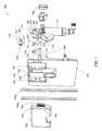
- FIG. 1shows an exploded, perspective view of an occlusion assembly from a front angle in accordance with an embodiment of the present disclosure
- FIG. 2shows an exploded, perspective view of the occlusion assembly of FIG. 1 from a back angle
- FIG. 3shows a front, perspective view of the occlusion assembly of FIG. 1 with the door open and the button pressed to illustrate loading of a tube;
- FIG. 4shows a close-up perspective view of the occlusion assembly of FIG. 1 , showing the door engaging a switch when the door is closed;
- FIG. 5shows the front of the occlusion assembly of FIG. 1 without the door and frame to illustrate the arms fully occluding flexible tubes;
- FIG. 6shows the front of the occlusion assembly of FIG. 1 without the door and frame to illustrate the arms in a non-occluding position
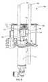
- FIG. 7is a rear/top perspective view of the occlusion assembly of FIG. 1 with an actuator arm in a fully retracted position;
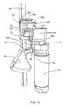
- FIG. 8is a rear perspective view of the occlusion assembly of FIG. 1 with an actuator arm in a fully extended position;
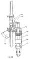
- FIG. 9shows a side perspective view of several working parts of the occlusion assembly of FIG. 1 in a non-occluding state
- FIG. 10shows a side perspective view of several working parts of the occlusion assembly of FIG. 1 in an occluding state
- FIG. 11shows a side, cross-sectional view of an actuator of the occlusion assembly of FIG. 1 , illustrating a location for a main spring for the assembly;
- FIG. 12shows the occlusion assembly of FIG. 1 mounted in a front panel assembly of a hemodialysis apparatus in accordance with an embodiment of the present disclosure.
- an occlusion assemblyfor compressing at least one flexible tube, for example a pair of flexible tubes.
- the occlusion assemblyincludes a tube occluder comprising a mechanism configured to occlude fluid flow within one or more flexible tubes, and in certain embodiments one or more pairs of flexible tubes.
- the tube occluder of the occlusion assemblycomprises at least one occluding member, and in a specific embodiment comprises an occluding member for each section of tubing placed within the assembly.
- each occluding memberis pressed or otherwise forced or urged into an occluding position by an element that slides along a side of the occluding member, causing the occluding member to pivot at its proximal end and to translate toward the tubing at its distal end.
- the elementis positioned between two occluding members and acts to spread the distal ends of the occluding members away from each other as they press against their respective tubes.
- a main springurges the spreading element toward the distal ends of the occluding elements into an occluding position.
- the spreading elementmay be moved against the biasing force of the main spring into a non-occluding position near the proximal ends of the occluding elements either manually through a button and linkage assembly coupled to the spreading element, or by control of a controller activating an actuator that is also coupled to the spreading element.
- a hinged doormay be configured to cover the occluding elements and their respective sections of tubing. Activation of the actuator may be prevented if the door is not properly closed over the occluding elements.
- a retention element to hold the spreading element in a non-occluding positionmay be enabled when the door is in an open position.
- Enabling the retention elementallows the spreader to be held in a non-occluding position without continued application of force by a user on the button or by continued activation of the actuator.
- the retention elementmay be disabled when the door is closed, so that the spreading element may be free to be moved into and out of an occluding position, either manually or via the actuator.
- FIGS. 1 and 2show exploded, perspective views of an occlusion assembly 700 in accordance with an embodiment of the present disclosure.
- FIG. 1shows an exploded, perspective view of the occlusion assembly 700 from a front angle
- FIG. 2shows an exploded, perspective view of the occlusion assembly 700 from a back angle.
- the occlusion assembly 700receives a pair of tubes 705 and is configured to occlude the tubes 705 using a pinching action at approximately the same level along the length of assembly 700 .
- the pinching actionreduces the size of an inner fluid pathway of each tube 705 to restrict the flow of fluid therethrough.
- the occlusion assembly 700may be used with an infusion pump, in a dialysis machine, in hemodialysis, in peritoneal dialysis, in hemofiltration, in hemodiafiltration, in intestinal dialysis, and the like.
- the occlusion assembly 700includes a frame 701 .
- the frame 701includes tabs or snaps 709 for securing the frame to corresponding slots on a front panel of a blood filtration device, such as a hemodialysis apparatus.
- the frame 701includes anvils or blocks 702 and 703 against which a tube 705 is compressed by the occluding ends 713 of a pair of occluding arms 710 and 711 , and a tube guide 704 to position each tube 705 against blocks 702 and 703 .
- the tube guide 704 and blocks 702 and 703are configured to each position a tube 705 in a predetermined position adjacent to each of the blocks 702 and 703 .
- the occlusion assembly 700also includes a door 706 which is pivotally mounted to the frame 701 . The door 706 can shut against the frame 701 to secure the tubes 705 between each of the blocks 702 and 703 and the tube guide 704 .
- the door 706includes a latch 707 , which may be co-molded with or otherwise attached to the door 706 via a hinge, such as for example a resilient, flexible base portion (e.g., via a living hinge) 708 to secure the door 706 to the frame 701 in a closed position.
- a latch 707may be pressed laterally to release a catch 740 from engagement with a corresponding slot 741 on frame 701 to open the door 706 .
- the occlusion assembly 700includes two arms 710 and 711 .
- the first arm 710includes a pivoting end 712 and an occluding end 713 ; likewise, the second arm 711 includes a pivoting end 714 and an occluding end 715 .
- the two arms 710 and 711operate together to occlude the tubes 705 when a manual actuator, such as button 716 , is released (or in other embodiments engaged) and door 706 is closed, or when an actuator 717 is deactivated
- FIG. 3shows a front, perspective view of the occlusion assembly 700 with the door 706 open and the button 716 pressed to illustrate release of occluding arms 710 and 711 to permit loading and unloading of the tubes 705 in accordance with an embodiment of the present disclosure.
- FIG. 5shows the front of the occlusion assembly 700 of FIG. 1 without the door 706 and frame 701 to illustrate the arms 710 and 711 fully occluding the tubes 705 a, b in accordance with an embodiment of the present disclosure. As shown in FIG.
- a wedge element or spreader 722contacts the facing sides of occluding arms 710 and 711 , which under spring force can apply pressure to occluding arms 710 and 711 to press the occluding ends 713 and 715 of occluding arms 710 and 711 against a portion of tubes 705 a, b .
- a usermay release the occluding arms 710 and 711 by pressing button 716 , which causes spreader 722 to withdraw away from occluding arms 710 and 711 , releasing the pressure of spreader 722 being applied to the distal ends of occluding arms 710 and 711 .
- the manual actuatore.g.
- button 716acts as an override mechanism to an automated actuator (such as, for example, a pneumatically operated piston/cylinder apparatus) connected to a tubing occluder element (e.g., the spreader 722 ).
- the manual actuatoris operatively coupled to the tubing occluder to cause essentially linear motion of at least a portion of the tubing occluder, moving the occluding member from an occluding position to a non-occluding position upon manual operation of the override mechanism by a user.
- an actuatormay release occluding arms 710 and 711 by causing spreader 722 to withdraw away from the occluding ends 713 , 715 of occluding arms 710 and 714 .
- spreader 722may be formed of, co-molded with, attached to or connected to a carriage assembly 723 , which in turn is connected to an actuating arm of the actuator (see, e.g., FIGS. 7-9 ).
- the actuatormay comprise, for example, a motor and gear assembly (e.g., rack and pinion assembly or worm-type gear assembly), a solenoid, a hydraulic cylinder or a pneumatic cylinder, among others.
- the actuatorcomprises a pneumatic cylinder 717 that causes an actuating arm comprising a piston arm 742 to extend linearly against a spring force (which in an embodiment may be a coil spring 745 within cylinder 717 as shown in FIG. 11 ).
- a spring forcewhich in an embodiment may be a coil spring 745 within cylinder 717 as shown in FIG. 11 .
- piston arm 742is connected to carriage 723 .
- actuator 717When activated by pneumatic pressure, actuator 717 extends piston arm 742 and moves carriage 723 and attached spreader 722 in a direction that withdraws spreader 722 from engagement with the distal ends 713 , 715 of the occluding arms 710 and 711 .
- occluding arm 711 , frame 701 , door 706 , block 703 and tube guide 704have been removed from FIGS. 9-11 ).
- a main spring that is either external or internal to cylinder/actuator 717may apply a biasing force to piston arm 742 or carriage 723 to cause spreader 722 to move occluding arms 710 and 711 to an occluding position.
- the occluding arms 710 and 711will default to an occluding mode, preventing the flow of fluid through tubes 705 .
- a coil spring 745may be placed within the cylinder 743 to provide a biasing force against which piston 744 may move piston arm 742 under pneumatic pressure.
- Pneumatic pressuremay be supplied to linear actuator 717 from a pressure source (e.g., a tank pressurized by a pump) regulated by an intervening electromechanical valve under control of an electronic controller.
- the carriage 723carries spreader 722 along the facing sides of the occluder arms 710 and 711 to rotate them into an occluding position.
- the first arm 710pivots about its pivoting end 712 to cause the occluding end 713 to press against first tube 705 a that is restrained by block 702 (see FIG. 5 ).
- the second arm 711pivots about its pivoting end 714 such that the occluding end 715 can press against second tube 705 b which is restrained by block 703 .
- FIGS. 6 and 9show occlusion assembly 700 in a non-occluding state (frame 701 , door 706 , blocks 702 , 703 , and other elements removed for clarity).
- the button 716is pressed or the linear actuator 717 is activated, the carriage 723 and attached spreader 722 move distally away from the actuator 717 , allowing occluder arms 710 and 711 to rotate about pivot points 712 and 714 into a non-occluding position.
- the elastic resilience of the tubes 705 a.bmay cause the arms 710 and 711 to pivot towards each other.
- small magnets (not explicitly shown) embedded in the arms 710 and 711pull the arms 710 and 711 towards each other to facilitate the retraction of the occluding ends 713 and 715 away from the tubes 705 .
- small springs (not shown)may bias occluding arms 710 and 711 to pivot toward each other, the spring constants being weak enough to be overcome by the main spring (e.g., spring 745 ) biasing carriage 723 or spreader 722 into retracted (occluding) positions.
- FIG. 4shows a perspective side view of the occlusion assembly 700 of FIG. 1 (frame 701 removed for clarity) showing the door 706 engaging a switch 720 when the door 706 is closed in accordance with an embodiment of the present disclosure.
- the hinge portion 708 of latch 707is coupled to an engagement member or catch 740 that can snap into a cooperating slot 741 of the frame 701 (see, e.g., FIGS. 1 and 3 ).
- a portion of the catch 740 of latch 707 of the door 706engages a spring-loaded switch 720 , which in an embodiment includes a spring arm 737 of the switch 720 .
- Engagement of switch 720 by closure of door 706signals an electronic controller (not shown) that the door 706 is properly closed, and that linear actuator 717 may be activated to release occluders 710 and 711 to allow fluid to flow through tubes 705 .
- the door 706 closure signalmay also cause the controller to perform other functions, such as, for example, instructing a pump coupled to the tubes 705 to begin pumping fluid within tubes 705 .
- FIG. 7shows the back of the occlusion assembly 700 of FIG. 1 with the linear actuator 717 in a fully retracted position (i.e., in the occluding position) in accordance with an embodiment of the present disclosure.
- FIG. 7shows the back side of the occlusion assembly 700 in the same configuration as shown for the front view of occlusion assembly 700 in FIG. 5 .
- FIG. 7shows several working parts of the occlusion assembly 700 of FIG. 1 to illustrate the operation of the actuator 717 and carriage 723 in accordance with an embodiment of the present disclosure.
- the carriage 723moves with the extension or retraction of the piston arm 742 or with the actuation of the button 716 .
- the carriage 723includes guides 724 attached to or co-molded with the carriage 723 .
- the guides 724guide the carriage 723 as it moves via actuation of the piston arm 742 or with the actuation of the button 716 .
- the guides 724interface with tracks 725 of the frame 701 (
- actuation of button 716 by a user or activation of actuator 717 by a controllercauses carriage 723 and spreader 722 to move into a non-occluding position, and a retaining element or assembly allows the non-occluding position to be held without further force being applied either by the user or by the actuator 717 .
- the carriage 723may incorporate a latching pin 726 to cooperate with a slot or hole in a retention member 718 .
- the retention member 718includes a surface 727 positioned to be contacted by pins 738 located on the inside of door 706 when it is closed (see, e.g., FIGS. 2 and 3 ).
- Through holes 739allow pins 738 to contact a portion of retention member 718 to displace it in a rearward direction.
- pins 738contact front plate 727 of retention member 718 .
- Retention member 718also includes a surface having a slot or hole 729 positioned to receive the head of a latching pin 726 , which in the illustrated embodiment comprises a horizontal plate 728 defining a receiving portion 729 .
- Retention member 718is arranged to slide within grooves or guides of the frame 701 (not shown) in response to contact by the pins 738 when the door 706 is closed or opened (see, e.g. FIG. 2 ).
- a spring 730 mounted on the frame 701may be biased to urge the retention member 718 forward to a stop feature (not shown) on the frame 701 so that opening the door 706 allows the retention member 718 to slide forward, re-aligning the receiving portion 729 in relation to the latching pin 726 .
- the pins 738 on the door 706press against the front plate 727 which compresses the spring 730 such that the receiving portion 729 of the horizontal plate 728 is positioned directly over the latching pin 726 .
- the area of the receiving portion 729is large enough to allow the latching pin 726 to be released by the retention member 718 , thereby allowing the carriage 723 to be subject to the spring force of the main spring 745 in the actuator 717 . If pneumatic pressure is not then being applied to the actuator 717 , the carriage 723 is then free to move into an occluding position.
- the retention member 718 in the disabled statei.e., inoperative state
- FIG. 8is a rear view of the occlusion assembly 700 with the actuator 717 activated, and the piston arm 742 in an extended position to place the occluding arms 710 , 711 in a non-occluding state.
- the head of the latching pin 726is noted to be above the plane of the horizontal plate 728 of the retention member 718 , and the recessed region 731 of the latching pin 726 is noted to be aligned with the receiving portion 729 of the retention member 718 .
- door 706is in a closed position, implying that the receiving portion 729 is in a sufficiently rearward position to prevent the latching pin 726 from being latched into the retention member 718 .
- the pins 738 of the door 706do not press against the front plate 727 and the spring 730 applies a force on the front plate 727 such that the receiving portion 729 of the retention member 718 is positioned to allow the latching pin 726 to engage an edge of the receiving portion 729 and latch to the retention member 718 .
- the latching pin 726moves into the receiving portion 729 pulling the front plate 727 rearward against the force of the spring 730 when the receiving portion 729 is positioned to latch to the latching pin 726 .
- a recessed region 731 below the head of latching pin 726becomes co-aligned with the horizontal plate 728 which moves as the edge of the receiving portion 729 moves into the recessed region 731 under the force of the spring 730 as applied to the front plate 727 .
- the receiving portion 729is positioned to release the latching pin 726 from the latch 718 .
- FIGS. 9 and 10show a side perspective view of several working parts of the occlusion assembly 700 of FIG. 1 , with frame 701 , blocks 702 , 703 , tube guide 704 , door 706 , occluding arm 711 and other parts removed for clarity.
- the piston arm 742is fully extended in accordance with an embodiment of the present disclosure.
- FIG. 9shows the latching pin 726 latched onto the retention member 718 . That is, assuming that door 706 is in an open position, the horizontal plate 728 is positioned by the force of spring 730 to engage the recessed region 731 of the latching pin 726 .
- FIG. 10shows a side, perspective view of the occlusion assembly 700 of FIG. 1 with the piston arm 742 in a fully retracted position, with certain elements removed as in FIG. 9 for clarity.
- the latching pin 726is shown to be completely disengaged from the retention member 718 ; and in the absence of an activating force on the actuator 717 or a pressing force on the button 716 , the piston arm 742 , carriage 723 and spreader 722 are free to retract under the force of a main spring 745 (see FIG. 11 ) biased against the extension of piston arm 742 .
- the spreader 722then moves toward the occluding ends 713 , 715 of the occluding arms 710 , 711 .
- the button 716pivots about a pivot 732 to raise a lever arm 733 when the button 716 is pressed.
- the lever arm 733is pivotally connected to a connecting member 734 via a proximal pivot 735 .
- the connecting member 734in turn is pivotally connected to the carriage 723 via a distal pivot 736 .
- FIG. 12shows the occlusion assembly 700 of FIG. 1 used in a front-panel assembly 911 of a dialysis system in accordance with an embodiment of the present disclosure.
- the occlusion assembly 700occludes flexible tubes 901 , 902 through which blood flows to and from a patient.
- the right side tube 902carries blood from a patient into a blood pump assembly 1000 and the left side tube 901 carries blood from a dialyzer 14 back to the patient after passing through an air trap 19 .
- the occlusion assembly 700can occlude the flow of blood through both of these patient tubes 801 , 802 simultaneously.
- the tubes 901 , 902are connected to a blood pump cassette or assembly 1000 .
- the blood pump cassette 1000is a modular unit that may be mounted onto and dismounted from the front-panel assembly 911 .
- Both of the patient tubes 901 , 902may be provided as an assembly with the blood pump cassette 1000 and air trap 19 , and may be loaded into the occlusion assembly 700 when the blood-pump cassette 1000 is mounted onto the front-panel assembly 911 .
- the occlusion assembly 700forms a permanent part of the front panel assembly 911 .
- pumps located on blood pump cassette 1000may be activated to pump blood from a patient through the right tube 902 , up through the blood pumps and through a dialyzer 14 . Blood processed by the dialyzer 14 then returns to the patient via tube 901 after first passing through an air trap 19 and an air-in-line detector 823 .
Landscapes
- Health & Medical Sciences (AREA)
- Heart & Thoracic Surgery (AREA)
- Engineering & Computer Science (AREA)
- Vascular Medicine (AREA)
- Animal Behavior & Ethology (AREA)
- Biomedical Technology (AREA)
- Hematology (AREA)
- Life Sciences & Earth Sciences (AREA)
- Anesthesiology (AREA)
- General Health & Medical Sciences (AREA)
- Public Health (AREA)
- Veterinary Medicine (AREA)
- Cardiology (AREA)
- General Engineering & Computer Science (AREA)
- Pulmonology (AREA)
- Mechanical Engineering (AREA)
- External Artificial Organs (AREA)
Abstract
Description
The present specification generally describes occluder devices for occluding flexible tubing, particularly in medical infusion systems.
Medical devices, such as hemodialysis machines, medical infusion pumps, plasmapheresis devices, and the like, often require the use of tubing to facilitate the flow of fluids, e.g., to or from a patient using such device. Such tubing in many instances is made of a flexible material and is designed to be collapsible in order to facilitate peristaltic pumping and/or occlusion of fluid flow via collapse of the lumen of the flexible tubing. A variety of tubing clamps and tubing occlusion devices are known. Certain of these devices can be integrated into a medical infusion device and automatically controlled. In certain applications, medical infusion devices must handle fluids that include ingredients that, due to leakage or other factors that may lead to presence of the fluid on the external surfaces of the tubing, can become sticky and or result in fouling or failure of certain conventional tubing occluder designs.
Described herein are occlusion assemblies configured to facilitate the opening and closing by occlusion of flexible tubing. In particular embodiments, the occlusion assemblies are associated with or form part of a medical infusion device, such as a hemodialysis device, peritoneal dialysis device, plasmapheresis device, etc., and may be controllably and automatically operated to facilitate fluid handling by such devices. The occlusion assemblies may be designed to position and immobilized the tubing and may include a frame or other support feature providing tubing guides and/or configured for attachment to or integration with a fluid handling assembly of a device of which they are part or with which they are used. The occlusion assemblies comprise a tubing occluder, which may be a mechanism constructed and positioned to apply a force to the tube(s) associated with the occlusion assembly to occlude the tubes and to release the force to allow the tubes to open for fluid flow. The occlusion assemblies and tubing occluders may be configured to include a single tube in certain cases, and in other cases to occlude multiple tubes, whether an odd number of tubes or an even number of tubes. Certain occlusion assemblies are specifically configured for occluding one or more pairs of tubes and may include tubing occluders having a separate occluding member for occluding each of the pair of collapsible tubes. The occlusion assemblies may include automatic actuators for operating the tubing occluders, and in certain cases also include a manual actuator to provide an override function. The occlusion assemblies may include a door designed and positioned to cover at least a portion of the tubes to be occluded and tubing occluder mechanism. Such occlusion assemblies may include safety features, for example, to prevent a release of occlusion force on the tubing when the door is not in a closed position and/or convenience features, for example a retainer mechanism to hold the tube occluder in a non-occluding position when the door is open with the tube occluder in the non-occluding position.
In one aspect, a variety of occlusion assemblies for occluding at least one collapsible tube of a medical infusion device are described. In certain embodiments, the occlusion assembly is configured for occluding at least one pair of collapsible tubes and comprises, for each pair of collapsible tubes, a first occluding member and a second occluding member, the first occluding member positioned adjacent to a first collapsible tube of the pair and the second occluding member positioned adjacent to a second collapsible to the pair, when the tubes are installed in the occlusion assembly for operation. The first occluding member and the second occluding member are further positioned adjacent from each other such that a space is defined between them. These space is on an opposite side of each occluding member then is the collapsible tube to which it is adjacent. The occlusion assembly further comprises a spreader positioned within the space between the occluding members and movable from a first position to a second position, wherein movement from the first position to the second position causes the spreader to force at least a portion of the first and second occluding members to move apart from each other to increase the size of the space between them and forced a tube-contacting portion of each occluding member against the collapsible tube to which it is adjacent to occlude the collapsible tube. The occlusion assembly further comprises at least one actuator constructed and positioned to move the spreader between the first and second positions.
In certain embodiments the occlusion assembly is configured for occluding at least one collapsible tube and comprises a frame comprising a tubing guide configured for positioning the collapsible tube, a tubing occluder mounted to the frame and comprising an occluding member constructed and positioned to controllably occlude or release occlusion of the collapsible tube, a door hingeably mounted to the frame and positioned to cover at least a portion of the collapsible tube and tubing occluder when in a closed position and to provide user access to the collapsible tube when in an open position, and a switch configured and positioned to detect when the door is in a closed position and to permit operation of the tubing occluder to release occlusion of the collapsible tube only when the door is in the closed position.
In certain embodiments and occlusion assembly for collapsing at least one collapsible tube comprises a tubing occluder comprising an occluding member constructed and positioned to controllably occlude or release occlusion of the collapsible tube, and automatic actuator operatively coupled to the tubing occluder to cause essentially linear motion of at least a portion of the tubing occluder to cause the occluding member to move from an occluding position to a non-occluding position, and an override mechanism operatively coupled to the tubing occluder to cause essentially linear motion of at least a portion of the tubing occluder to cause the occluding member to move from an occluding position to anon-occluding position upon manual operation of the override mechanism by a user.
In certain embodiments, and occlusion assembly for occluding at least one collapsible tube comprises a frame comprising a tubing guide configured for positioning the collapsible tube, a tubing occluder mounted to the frame and comprising an occluding member constructed and positioned to controllably occlude or release occlusion of the collapsible tube, a door hingeably mounted to the frame and positioned to cover at least a portion of the collapsible tube and tubing occluder when in a closed position and to provide user access to the collapsible tube when in an open position, and a retainer mechanism engaged by the door when the door is in the closed position and configured to permit operation of the tubing occluder to occlude or release occlusion of the collapsible tube when the door is in the closed position and configured to engage and retain the tubing occluder in a non-occluding configuration when the door is opened while the tubing occluder is positioned in the non-occluding configuration.
In another aspect a method of operating an occlusion assembly for occluding at least one pair of collapsible tubes of a medical infusion devices disclosed. In one embodiment, the method involves moving a spreader of the occlusion assembly from a first position to a second position, wherein the spreader is positioned within a space defined between a first occluding member and a second occluding member to cause the spreader to force at least a portion of the first and second occluding members to move apart from each other to increase the size of the space between them and force a tube-contacting portion of each occluding member against a collapsible tube to which it is adjacent to occlude the collapsible tube.
Other advantages and novel features of the present invention will become apparent from the following detailed description of various non-limiting embodiments when considered in conjunction with the accompanying figures. In cases where the present specification and a document incorporated by reference include conflicting and/or inconsistent disclosure, the present specification shall control.
The accompanying drawings are schematic are not intended to be drawn to scale. In the figures, each identical, or substantially similar component that is illustrated in various figures is typically represented by a single numeral or notation. For purposes of clarity, not every component is labeled in every figure, nor is every component of each embodiment of the invention shown where illustration is not necessary to allow those of ordinary skill in the art to understand the invention. In the drawings:
In accordance with one aspect of the disclosed invention, an occlusion assembly for compressing at least one flexible tube, for example a pair of flexible tubes is described. The occlusion assembly includes a tube occluder comprising a mechanism configured to occlude fluid flow within one or more flexible tubes, and in certain embodiments one or more pairs of flexible tubes. In certain embodiments, the tube occluder of the occlusion assembly comprises at least one occluding member, and in a specific embodiment comprises an occluding member for each section of tubing placed within the assembly. In certain such embodiments, each occluding member is pressed or otherwise forced or urged into an occluding position by an element that slides along a side of the occluding member, causing the occluding member to pivot at its proximal end and to translate toward the tubing at its distal end. In an embodiment, the element is positioned between two occluding members and acts to spread the distal ends of the occluding members away from each other as they press against their respective tubes. In a preferred option, a main spring urges the spreading element toward the distal ends of the occluding elements into an occluding position. The spreading element may be moved against the biasing force of the main spring into a non-occluding position near the proximal ends of the occluding elements either manually through a button and linkage assembly coupled to the spreading element, or by control of a controller activating an actuator that is also coupled to the spreading element. A hinged door may be configured to cover the occluding elements and their respective sections of tubing. Activation of the actuator may be prevented if the door is not properly closed over the occluding elements. Optionally, a retention element to hold the spreading element in a non-occluding position may be enabled when the door is in an open position. Enabling the retention element allows the spreader to be held in a non-occluding position without continued application of force by a user on the button or by continued activation of the actuator. The retention element may be disabled when the door is closed, so that the spreading element may be free to be moved into and out of an occluding position, either manually or via the actuator.
Theocclusion assembly 700 receives a pair oftubes 705 and is configured to occlude thetubes 705 using a pinching action at approximately the same level along the length ofassembly 700. The pinching action reduces the size of an inner fluid pathway of eachtube 705 to restrict the flow of fluid therethrough. Theocclusion assembly 700 may be used with an infusion pump, in a dialysis machine, in hemodialysis, in peritoneal dialysis, in hemofiltration, in hemodiafiltration, in intestinal dialysis, and the like.
Theocclusion assembly 700 includes aframe 701. In some embodiments, theframe 701 includes tabs or snaps709 for securing the frame to corresponding slots on a front panel of a blood filtration device, such as a hemodialysis apparatus.
Theframe 701 includes anvils or blocks702 and703 against which atube 705 is compressed by the occluding ends713 of a pair of occludingarms tube guide 704 to position eachtube 705 againstblocks tube guide 704 and blocks702 and703 are configured to each position atube 705 in a predetermined position adjacent to each of theblocks occlusion assembly 700 also includes adoor 706 which is pivotally mounted to theframe 701. Thedoor 706 can shut against theframe 701 to secure thetubes 705 between each of theblocks tube guide 704. Thedoor 706 includes alatch 707, which may be co-molded with or otherwise attached to thedoor 706 via a hinge, such as for example a resilient, flexible base portion (e.g., via a living hinge)708 to secure thedoor 706 to theframe 701 in a closed position. As shown inFIGS. 1, 3, and 4 , alatch 707 may be pressed laterally to release acatch 740 from engagement with acorresponding slot 741 onframe 701 to open thedoor 706.
Theocclusion assembly 700 includes twoarms first arm 710 includes a pivotingend 712 and an occludingend 713; likewise, thesecond arm 711 includes a pivotingend 714 and an occludingend 715. The twoarms tubes 705 when a manual actuator, such asbutton 716, is released (or in other embodiments engaged) anddoor 706 is closed, or when anactuator 717 is deactivated
Similarly, activation of an actuator may release occludingarms spreader 722 to withdraw away from the occluding ends713,715 of occludingarms FIG. 1 ,spreader 722 may be formed of, co-molded with, attached to or connected to acarriage assembly 723, which in turn is connected to an actuating arm of the actuator (see, e.g.,FIGS. 7-9 ). The actuator may comprise, for example, a motor and gear assembly (e.g., rack and pinion assembly or worm-type gear assembly), a solenoid, a hydraulic cylinder or a pneumatic cylinder, among others. In a preferred embodiment, the actuator comprises apneumatic cylinder 717 that causes an actuating arm comprising apiston arm 742 to extend linearly against a spring force (which in an embodiment may be acoil spring 745 withincylinder 717 as shown inFIG. 11 ). As shown inFIG. 11 , in a perspective side view of a pneumatically operatedlinear actuator 717,piston arm 742 is connected tocarriage 723. When activated by pneumatic pressure,actuator 717 extendspiston arm 742 and movescarriage 723 and attachedspreader 722 in a direction that withdrawsspreader 722 from engagement with the distal ends713,715 of the occludingarms arm 711,frame 701,door 706, block703 andtube guide 704, among other elements, have been removed fromFIGS. 9-11 ). Preferably, a main spring that is either external or internal to cylinder/actuator 717 may apply a biasing force topiston arm 742 orcarriage 723 to causespreader 722 to move occludingarms arms tubes 705. As illustrated in a cross-sectional view ofocclusion assembly 700 inFIG. 11 , in an embodiment, acoil spring 745 may be placed within thecylinder 743 to provide a biasing force against whichpiston 744 may movepiston arm 742 under pneumatic pressure. Pneumatic pressure may be supplied tolinear actuator 717 from a pressure source (e.g., a tank pressurized by a pump) regulated by an intervening electromechanical valve under control of an electronic controller.
As shown inFIGS. 5 and 10 , when thelinear actuator 717 is fully retracted, thecarriage 723 carriesspreader 722 along the facing sides of theoccluder arms first arm 710 pivots about its pivotingend 712 to cause the occludingend 713 to press againstfirst tube 705athat is restrained by block702 (seeFIG. 5 ). Thesecond arm 711 pivots about its pivotingend 714 such that the occludingend 715 can press againstsecond tube 705bwhich is restrained byblock 703.
Engagement ofswitch 720 by closure ofdoor 706 signals an electronic controller (not shown) that thedoor 706 is properly closed, and thatlinear actuator 717 may be activated to releaseoccluders tubes 705. Thedoor 706 closure signal may also cause the controller to perform other functions, such as, for example, instructing a pump coupled to thetubes 705 to begin pumping fluid withintubes 705.
In an optional embodiment, whendoor 706 is open, actuation ofbutton 716 by a user or activation ofactuator 717 by a controller causescarriage 723 andspreader 722 to move into a non-occluding position, and a retaining element or assembly allows the non-occluding position to be held without further force being applied either by the user or by theactuator 717. In an exemplary embodiment shown inFIG. 7 , thecarriage 723 may incorporate alatching pin 726 to cooperate with a slot or hole in aretention member 718. Theretention member 718 includes asurface 727 positioned to be contacted bypins 738 located on the inside ofdoor 706 when it is closed (see, e.g.,FIGS. 2 and 3 ). Through holes739 (see, e.g.FIGS. 1 and 3 ) allowpins 738 to contact a portion ofretention member 718 to displace it in a rearward direction. In the illustrated embodiment, pins738 contactfront plate 727 ofretention member 718.Retention member 718 also includes a surface having a slot orhole 729 positioned to receive the head of alatching pin 726, which in the illustrated embodiment comprises ahorizontal plate 728 defining a receivingportion 729.Retention member 718 is arranged to slide within grooves or guides of the frame701 (not shown) in response to contact by thepins 738 when thedoor 706 is closed or opened (see, e.g.FIG. 2 ). Aspring 730 mounted on theframe 701 may be biased to urge theretention member 718 forward to a stop feature (not shown) on theframe 701 so that opening thedoor 706 allows theretention member 718 to slide forward, re-aligning the receivingportion 729 in relation to thelatching pin 726. When thedoor 706 is closed (seeFIG. 1 or 2 ), thepins 738 on thedoor 706 press against thefront plate 727 which compresses thespring 730 such that the receivingportion 729 of thehorizontal plate 728 is positioned directly over the latchingpin 726. Upon alignment of the receivingportion 729 with the latchingpin 726, the area of the receivingportion 729 is large enough to allow thelatching pin 726 to be released by theretention member 718, thereby allowing thecarriage 723 to be subject to the spring force of themain spring 745 in theactuator 717. If pneumatic pressure is not then being applied to theactuator 717, thecarriage 723 is then free to move into an occluding position. Theretention member 718 in the disabled state (i.e., inoperative state) allows the latchingpin 726 to move freely through the receivingportion 729 as thecarriage 723 moves between the fully extended position and the fully retracted position.
When thedoor 706 is sufficiently opened, thepins 738 of thedoor 706 do not press against thefront plate 727 and thespring 730 applies a force on thefront plate 727 such that the receivingportion 729 of theretention member 718 is positioned to allow thelatching pin 726 to engage an edge of the receivingportion 729 and latch to theretention member 718. The latchingpin 726 moves into the receivingportion 729 pulling thefront plate 727 rearward against the force of thespring 730 when the receivingportion 729 is positioned to latch to thelatching pin 726. When the head of latchingpin 726 moves sufficiently through the receivingportion 729, a recessedregion 731 below the head of latchingpin 726 becomes co-aligned with thehorizontal plate 728 which moves as the edge of the receivingportion 729 moves into the recessedregion 731 under the force of thespring 730 as applied to thefront plate 727. When thepins 738 of thedoor 706 sufficiently engage thefront plate 727, the receivingportion 729 is positioned to release thelatching pin 726 from thelatch 718. Thus, when thedoor 706 is open, thecarriage 723 andspreader 722 can be held in a non-occluding position without the continuous application of force by theactuator 717 or by a user pressing against thebutton 716. This permits a user to load and unload tubing fromocclusion assembly 700 without simultaneously having to apply force on thebutton 716. However, upon the closing of thedoor 706, theretention member 718 is no longer operative, and in the absence of continued application of force by either theactuator 717 or through thebutton 716, thecarriage 723 andspreader 722 will move into a position to cause the occludingarms
Thetubes assembly 1000. Theblood pump cassette 1000 is a modular unit that may be mounted onto and dismounted from the front-panel assembly 911. Both of thepatient tubes blood pump cassette 1000 andair trap 19, and may be loaded into theocclusion assembly 700 when the blood-pump cassette 1000 is mounted onto the front-panel assembly 911. In this embodiment, theocclusion assembly 700 forms a permanent part of thefront panel assembly 911.
When theocclusion assembly 700 is in the non-occluding state, pumps located onblood pump cassette 1000 may be activated to pump blood from a patient through theright tube 902, up through the blood pumps and through adialyzer 14. Blood processed by thedialyzer 14 then returns to the patient viatube 901 after first passing through anair trap 19 and an air-in-line detector 823.
While several embodiments of the invention have been described and illustrated herein, those of ordinary skill in the art will readily envision a variety of other means and structures for performing the functions and/or obtaining the results or advantages described herein, and each of such variations, modifications and improvements is deemed to be within the scope of the present invention. More generally, those skilled in the art would readily appreciate that all parameters, dimensions, materials, and configurations described herein are meant to be exemplary and that actual parameters, dimensions, materials, and configurations will depend upon specific applications for which the teachings of the present invention are used. Those skilled in the art will recognize, or be able to ascertain using no more than routine experimentation, many equivalents to the specific embodiments of the invention described herein. It is, therefore, to be understood that the foregoing embodiments are presented by way of example only and that, within the scope of the appended claims and equivalents thereto, the invention may be practiced otherwise than as specifically described. The present invention is directed to each individual feature, system, material and/or method described herein. In addition, any combination of two or more such features, systems, materials and/or methods, provided that such features, systems, materials and/or methods are not mutually inconsistent, is included within the scope of the present invention.
Claims (8)
1. An occlusion assembly for occluding at least one pair of collapsible tubes of a medical infusion device, comprising:
for each pair of collapsible tubes, a first occluding member and a second occluding member, the first occluding member positioned adjacent to a first collapsible tube of the pair and the second occluding member positioned adjacent to a second collapsible tube of the pair, when the tubes are installed in the occlusion assembly for operation, the first occluding member and the second occluding member being further positioned opposite each other such that a space is defined between the first occluding member and the second occluding member, the space being on an opposite side of each occluding member than is the collapsible tube to which it is adjacent;
a spreader positioned within the space and movable within the space from a first position to a second position,
wherein movement from the first position to the second position causes the spreader to force at least a portion of both the first and second occluding members to move apart from each other to increase the size of the space and move a tube-contacting portion of each occluding member against the collapsible tube to which it is adjacent to occlude the collapsible tube; and
at least one actuator constructed and positioned to move the spreader between the first position and the second position,
wherein the spreader is configured to move along a substantially linear pathway that is substantially perpendicular to the direction of movement of the tube-contacting portion of each occluding member.
2. The occlusion assembly ofclaim 1 , further comprising a frame comprising a tubing guide configured for positioning the collapsible tubes and for mounting the first and second occluding members and the spreader.
3. The occlusion assembly ofclaim 2 , wherein the spreader is wedge shaped and coupled to the at least one actuator, and wherein the at least one actuator causes the spreader to move in an essentially linear path from the first position to the second position to engage with the first and second occluding members and move them apart from each other.
4. The occlusion assembly ofclaim 1 , wherein the occlusion assembly is configured so that the collapsible tubes are occluded in the absence of a force applied by the actuator to cause release of occlusion.
5. The occlusion assembly ofclaim 4 , wherein the actuator comprises a biasing element configured to provide a restoring force causing occlusion of the collapsible tubes in the absence of positive actuation of the actuator to overcome the restoring force and release occlusion of the collapsible tubes.
6. The occlusion assembly ofclaim 1 , wherein the occlusion assembly comprises a portion of a fluid handling assembly of a dialysis system.
7. The occlusion assembly ofclaim 1 , wherein the occlusion assembly further comprises at least one of the collapsible tube mounted thereto.
8. The occlusion assembly ofclaim 1 , wherein the actuator comprises a pneumatically powered actuator.
Priority Applications (4)
| Application Number | Priority Date | Filing Date | Title |
|---|---|---|---|
| US13/480,236US9364655B2 (en) | 2012-05-24 | 2012-05-24 | Flexible tubing occlusion assembly |
| US15/181,234US9700711B2 (en) | 2012-05-24 | 2016-06-13 | Flexible tubing occlusion assembly |
| US15/637,738US10850089B2 (en) | 2012-05-24 | 2017-06-29 | Flexible tubing occlusion assembly |
| US17/107,645US11766554B2 (en) | 2012-05-24 | 2020-11-30 | Flexible tubing occlusion assembly |
Applications Claiming Priority (1)
| Application Number | Priority Date | Filing Date | Title |
|---|---|---|---|
| US13/480,236US9364655B2 (en) | 2012-05-24 | 2012-05-24 | Flexible tubing occlusion assembly |
Related Child Applications (1)
| Application Number | Title | Priority Date | Filing Date |
|---|---|---|---|
| US15/181,234DivisionUS9700711B2 (en) | 2012-05-24 | 2016-06-13 | Flexible tubing occlusion assembly |
Publications (2)
| Publication Number | Publication Date |
|---|---|
| US20130317454A1 US20130317454A1 (en) | 2013-11-28 |
| US9364655B2true US9364655B2 (en) | 2016-06-14 |
Family
ID=49622161
Family Applications (4)
| Application Number | Title | Priority Date | Filing Date |
|---|---|---|---|
| US13/480,236Active2034-10-26US9364655B2 (en) | 2012-05-24 | 2012-05-24 | Flexible tubing occlusion assembly |
| US15/181,234ActiveUS9700711B2 (en) | 2012-05-24 | 2016-06-13 | Flexible tubing occlusion assembly |
| US15/637,738Active2033-01-26US10850089B2 (en) | 2012-05-24 | 2017-06-29 | Flexible tubing occlusion assembly |
| US17/107,645Active2033-02-25US11766554B2 (en) | 2012-05-24 | 2020-11-30 | Flexible tubing occlusion assembly |
Family Applications After (3)
| Application Number | Title | Priority Date | Filing Date |
|---|---|---|---|
| US15/181,234ActiveUS9700711B2 (en) | 2012-05-24 | 2016-06-13 | Flexible tubing occlusion assembly |
| US15/637,738Active2033-01-26US10850089B2 (en) | 2012-05-24 | 2017-06-29 | Flexible tubing occlusion assembly |
| US17/107,645Active2033-02-25US11766554B2 (en) | 2012-05-24 | 2020-11-30 | Flexible tubing occlusion assembly |
Country Status (1)
| Country | Link |
|---|---|
| US (4) | US9364655B2 (en) |
Cited By (23)
| Publication number | Priority date | Publication date | Assignee | Title |
|---|---|---|---|---|
| US9535021B2 (en) | 2007-02-27 | 2017-01-03 | Deka Products Limited Partnership | Sensor apparatus systems, devices and methods |
| US9555179B2 (en) | 2007-02-27 | 2017-01-31 | Deka Products Limited Partnership | Hemodialysis systems and methods |
| US9597442B2 (en) | 2007-02-27 | 2017-03-21 | Deka Products Limited Partnership | Air trap for a medical infusion device |
| US9603985B2 (en) | 2007-02-27 | 2017-03-28 | Deka Products Limited Partnership | Blood treatment systems and methods |
| US9700711B2 (en) | 2012-05-24 | 2017-07-11 | Deka Products Limited Partnership | Flexible tubing occlusion assembly |
| US9724458B2 (en) | 2011-05-24 | 2017-08-08 | Deka Products Limited Partnership | Hemodialysis system |
| US9839776B2 (en) | 2008-01-23 | 2017-12-12 | Deka Products Limited Partnership | Fluid flow occluder and methods of use for medical treatment systems |
| US9951768B2 (en) | 2007-02-27 | 2018-04-24 | Deka Products Limited Partnership | Cassette system integrated apparatus |
| US9987407B2 (en) | 2007-02-27 | 2018-06-05 | Deka Products Limited Partnership | Blood circuit assembly for a hemodialysis system |
| US9999717B2 (en) | 2011-05-24 | 2018-06-19 | Deka Products Limited Partnership | Systems and methods for detecting vascular access disconnection |
| US10201650B2 (en) | 2009-10-30 | 2019-02-12 | Deka Products Limited Partnership | Apparatus and method for detecting disconnection of an intravascular access device |
| US10302075B2 (en) | 2006-04-14 | 2019-05-28 | Deka Products Limited Partnership | Fluid pumping systems, devices and methods |
| US10463774B2 (en) | 2007-02-27 | 2019-11-05 | Deka Products Limited Partnership | Control systems and methods for blood or fluid handling medical devices |
| US10537671B2 (en) | 2006-04-14 | 2020-01-21 | Deka Products Limited Partnership | Automated control mechanisms in a hemodialysis apparatus |
| US10780210B2 (en) | 2007-02-27 | 2020-09-22 | Deka Products Limited Partnership | Enclosure for a portable hemodialysis system |
| US10799628B2 (en) | 2007-02-27 | 2020-10-13 | Deka Products Limited Partnership | Cassette system integrated apparatus |
| US11103625B2 (en) | 2011-05-24 | 2021-08-31 | Deka Products Limited Partnership | Blood treatment systems and methods |
| US11311656B2 (en) | 2007-02-27 | 2022-04-26 | Deka Products Limited Partnership | Modular assembly for a portable hemodialysis system |
| US11371498B2 (en) | 2018-03-30 | 2022-06-28 | Deka Products Limited Partnership | Liquid pumping cassettes and associated pressure distribution manifold and related methods |
| US11939566B2 (en) | 2016-11-07 | 2024-03-26 | Deka Products Limited Partnership | System and method for creating tissue |
| US12026271B2 (en) | 2014-05-27 | 2024-07-02 | Deka Products Limited Partnership | Control systems and methods for blood or fluid handling medical devices |
| US12171922B2 (en) | 2008-08-27 | 2024-12-24 | Deka Products Limited Partnership | Blood treatment systems and methods |
| US12421952B2 (en) | 2013-03-15 | 2025-09-23 | Deka Products Limited Partnership | Reciprocating diaphragm pumps for blood treatment systems and methods |
Families Citing this family (16)
| Publication number | Priority date | Publication date | Assignee | Title |
|---|---|---|---|---|
| US20140199193A1 (en) | 2007-02-27 | 2014-07-17 | Deka Products Limited Partnership | Blood treatment systems and methods |
| US8357298B2 (en) | 2007-02-27 | 2013-01-22 | Deka Products Limited Partnership | Hemodialysis systems and methods |
| US8863772B2 (en) | 2008-08-27 | 2014-10-21 | Deka Products Limited Partnership | Occluder for a medical infusion system |
| WO2012129501A2 (en) | 2011-03-23 | 2012-09-27 | Nxstage Medical, Inc. | Peritoneal dialysis systems, devices, and methods |
| US9861733B2 (en) | 2012-03-23 | 2018-01-09 | Nxstage Medical Inc. | Peritoneal dialysis systems, devices, and methods |
| WO2014170325A1 (en)* | 2013-04-16 | 2014-10-23 | Intervet International B.V. | Apparatus for injecting a liquid into live animals |
| DE102015014741A1 (en)* | 2015-11-13 | 2017-05-18 | Fresenius Medical Care Deutschland Gmbh | Hose clamp for a blood treatment device |
| WO2017109085A1 (en)* | 2015-12-22 | 2017-06-29 | Ge Healthcare Bio-Sciences Corp. | Improvements in and relating to cell harvesting apparatus |
| CN106641325B (en)* | 2017-02-24 | 2022-12-23 | 四川天府南格尔生物医学有限公司 | Novel medical diaphragm type pinch valve |
| EP3641850B1 (en) | 2017-06-24 | 2024-10-09 | NxStage Medical Inc. | Peritoneal dialysis fluid preparation systems |
| JP2021516089A (en) | 2018-02-28 | 2021-07-01 | ネクステージ メディカル インコーポレイテッド | Fluid preparation and treatment equipment, methods, and systems |
| CN112156250A (en)* | 2018-09-28 | 2021-01-01 | 德州飚丰信息技术有限公司 | Automatic hydrops drainage device |
| CN109513066B (en)* | 2018-10-30 | 2020-12-01 | 青岛市精神卫生中心 | A drip controller |
| CN111566401B (en) | 2018-12-10 | 2024-01-30 | 科尔布鲁克博松及桑德斯(产品)有限公司 | Monitor support structure |
| USD935458S1 (en) | 2018-12-10 | 2021-11-09 | Colebrook Bosson & Saunders (Products) Limited | Support structure |
| US11202859B2 (en)* | 2019-11-20 | 2021-12-21 | B Braun Medical Inc. | Cassette with free flow prevention for infusion pump |
Citations (123)
| Publication number | Priority date | Publication date | Assignee | Title |
|---|---|---|---|---|
| US350850A (en) | 1886-10-12 | tatum | ||
| US2816514A (en) | 1954-09-17 | 1957-12-17 | Designers For Industry Inc | Vibratory pump |
| US2985192A (en) | 1959-07-24 | 1961-05-23 | American Cyanamid Co | Double pinch valve |
| US3111125A (en) | 1961-11-06 | 1963-11-19 | Rudolf R Schulte | Drainage device |
| US3335753A (en) | 1964-03-02 | 1967-08-15 | Kiser Ohlmann Inc | Control valve with adjustable flow rate, especially for dispensing machines |
| US3411534A (en) | 1966-12-28 | 1968-11-19 | Tracor | Four-way valve |
| US3539081A (en) | 1968-07-05 | 1970-11-10 | Jet Spray Cooler Inc | Valve for beverage dispensers |
| US3568214A (en) | 1968-07-24 | 1971-03-09 | Univ Utah | Artificial heart system and method of pumping blood by electromagnetically pulsed fluid |
| US3575161A (en) | 1968-03-07 | 1971-04-20 | Seymour B London | Valve for biological systems |
| US3759483A (en) | 1971-05-14 | 1973-09-18 | T Baxter | Fluid actuated control valve |
| US3827561A (en) | 1972-09-20 | 1974-08-06 | Milton Roy Co | Deaerator for dialysis system |
| US3918490A (en) | 1973-12-20 | 1975-11-11 | George Goda | Fluid switching apparatus |
| US3985134A (en)* | 1973-11-26 | 1976-10-12 | Rhone-Poulenc S.A. | Extracorporeal blood circuit |
| US3991972A (en) | 1975-04-21 | 1976-11-16 | Itl Technology Inc. | Electrically operated proportionate valve |
| US4061142A (en) | 1976-06-16 | 1977-12-06 | Sandoz, Inc. | Apparatus for controlling blood flow |
| US4096211A (en) | 1975-10-01 | 1978-06-20 | Regie Nationale Des Usines Renault | Variable flow elastic nozzle |
| US4161264A (en) | 1977-06-17 | 1979-07-17 | Johnson Bryan E | Fluid metering and mixing device having inlet and outlet valves |
| US4259985A (en) | 1978-12-18 | 1981-04-07 | Brunswick Corporation | Three-way solenoid-operated pinch valve assembly |
| US4322054A (en) | 1980-12-29 | 1982-03-30 | Red Valve Company, Inc. | Pinch valve |
| US4398908A (en) | 1980-11-28 | 1983-08-16 | Siposs George G | Insulin delivery system |
| US4479762A (en) | 1982-12-28 | 1984-10-30 | Baxter Travenol Laboratories, Inc. | Prepackaged fluid processing module having pump and valve elements operable in response to applied pressures |
| US4479760A (en) | 1982-12-28 | 1984-10-30 | Baxter Travenol Laboratories, Inc. | Actuator apparatus for a prepackaged fluid processing module having pump and valve elements operable in response to applied pressures |
| US4479761A (en) | 1982-12-28 | 1984-10-30 | Baxter Travenol Laboratories, Inc. | Actuator apparatus for a prepackaged fluid processing module having pump and valve elements operable in response to externally applied pressures |
| US4484599A (en) | 1983-09-23 | 1984-11-27 | Organon Teknika Corporation | Pinch-type pressure- or flow-regulating valve |
| US4501405A (en) | 1983-06-21 | 1985-02-26 | Bunnell Life Systems, Inc. | Frictionless valve/pump |
| US4575007A (en) | 1984-03-02 | 1986-03-11 | Regina Corporation | Mixing control for water and cleaning fluid |
| US4585442A (en) | 1984-07-26 | 1986-04-29 | Ivy Medical, Inc. | Miniature intravenous infusion rate controller |
| US4594058A (en) | 1984-06-01 | 1986-06-10 | The Johns Hopkins University | Single valve diaphragm pump with decreased sensitivity to ambient conditions |
| US4623450A (en) | 1981-06-16 | 1986-11-18 | Hospal Industrie | Artificial kidney |
| US4645489A (en) | 1982-11-30 | 1987-02-24 | Beta Phase, Inc. | Fluid delivery apparatus with shape-memory flow control element |
| US4725269A (en) | 1983-05-10 | 1988-02-16 | Critikon, Inc. | Crimp valve assembly |
| US4778451A (en) | 1986-03-04 | 1988-10-18 | Kamen Dean L | Flow control system using boyle's law |
| US4826482A (en) | 1986-03-04 | 1989-05-02 | Kamen Dean L | Enhanced pressure measurement flow control system |
| US4828543A (en) | 1986-04-03 | 1989-05-09 | Weiss Paul I | Extracorporeal circulation apparatus |
| US4833329A (en) | 1987-11-20 | 1989-05-23 | Mallinckrodt, Inc. | System for generating and containerizing radioisotopes |
| US4878646A (en) | 1988-08-15 | 1989-11-07 | Critkon, Inc. | Pinch valve mechanism for a parenteral infusion system |
| US4969486A (en) | 1989-03-24 | 1990-11-13 | Puzio Eugene T | Flow control apparatus |
| US4976162A (en) | 1987-09-03 | 1990-12-11 | Kamen Dean L | Enhanced pressure measurement flow control system |
| US5002471A (en) | 1987-07-20 | 1991-03-26 | D.F. Laboratories Ltd. | Disposable cell and diaphragm pump for use of same |
| US5088515A (en) | 1989-05-01 | 1992-02-18 | Kamen Dean L | Valve system with removable fluid interface |
| US5105981A (en) | 1990-11-19 | 1992-04-21 | Thomas Gehman | Selectively shakeable freestanding particulate matter reservoir |
| US5113906A (en) | 1989-09-07 | 1992-05-19 | Hoegner Marcelo A | Multiple rotary control valve for use with a sterilizing apparatus |
| US5178182A (en) | 1986-03-04 | 1993-01-12 | Deka Products Limited Partnership | Valve system with removable fluid interface |
| US5300044A (en) | 1991-09-26 | 1994-04-05 | Baxter International Inc. | Intravenous tube safety apparatus |
| US5318414A (en) | 1990-06-07 | 1994-06-07 | Humanteknik Ab | Valve arrangement and positive-displacement pump |
| US5328487A (en)* | 1992-09-23 | 1994-07-12 | Jovanka Starchevich | Intravenous tube mounting and control apparatus |
| USD350823S (en) | 1993-02-24 | 1994-09-20 | Deka Products Limited Partnership | Rigid portion of disposable parenteral-fluid cassette |
| US5350357A (en) | 1993-03-03 | 1994-09-27 | Deka Products Limited Partnership | Peritoneal dialysis systems employing a liquid distribution and pumping cassette that emulates gravity flow |
| US5351686A (en) | 1990-10-06 | 1994-10-04 | In-Line Diagnostics Corporation | Disposable extracorporeal conduit for blood constituent monitoring |
| US5411472A (en) | 1992-07-30 | 1995-05-02 | Galen Medical, Inc. | Low trauma blood recovery system |
| US5413566A (en) | 1993-03-16 | 1995-05-09 | Micropump Corporation | Line clamp |
| US5423738A (en) | 1992-03-13 | 1995-06-13 | Robinson; Thomas C. | Blood pumping and processing system |
| US5429485A (en) | 1992-12-18 | 1995-07-04 | Minnesota Mining And Manufacturing Company | Plural inlet pumping cassette with integral manifold |
| US5431626A (en) | 1993-03-03 | 1995-07-11 | Deka Products Limited Partnership | Liquid pumping mechanisms for peritoneal dialysis systems employing fluid pressure |
| US5438510A (en) | 1993-03-03 | 1995-08-01 | Deka Products Limited Partnership | User interface and monitoring functions for automated peritoneal dialysis systems |
| US5441231A (en) | 1994-05-17 | 1995-08-15 | Payne; Barrett M. M. | Valve closing actuator |
| US5472325A (en) | 1991-01-18 | 1995-12-05 | Uno Plast A/S | Suction pump for draining body fluids from body cavities |
| US5474683A (en) | 1993-03-03 | 1995-12-12 | Deka Products Limited Partnership | Peritoneal dialysis systems and methods employing pneumatic pressure and temperature-corrected liquid volume measurements |
| US5575310A (en) | 1986-03-04 | 1996-11-19 | Deka Products Limited Partnership | Flow control system with volume-measuring system using a resonatable mass |
| US5578012A (en) | 1995-04-24 | 1996-11-26 | Deka Products Limited Partnership | Medical fluid pump |
| WO1996040320A1 (en) | 1995-06-07 | 1996-12-19 | Cobe Laboratories, Inc. | Technique for priming and recirculating fluid through a dialysis machine |
| US5628908A (en) | 1993-03-03 | 1997-05-13 | Deka Products Limited Partnership | Peritoneal dialysis systems and methods employing a liquid distribution and pump cassette with self-contained air isolation and removal |
| US5692729A (en) | 1996-02-16 | 1997-12-02 | Vision-Sciences, Inc. | Pressure equalized flow control apparatus and method for endoscope channels |
| US5901745A (en) | 1997-06-19 | 1999-05-11 | The Hoover Company | Multi-solution dispensing valve |
| US5931648A (en) | 1995-05-30 | 1999-08-03 | Servicio Regional De Salud, De La Consejeria De Salud De La Comunidad De Madrid | Vacuum actuated tubular blood pumping device with active values and application of the same |
| US5938634A (en) | 1995-09-08 | 1999-08-17 | Baxter International Inc. | Peritoneal dialysis system with variable pressure drive |
| US6041801A (en) | 1998-07-01 | 2000-03-28 | Deka Products Limited Partnership | System and method for measuring when fluid has stopped flowing within a line |
| US6105416A (en) | 1998-10-16 | 2000-08-22 | Geo-Centers, Inc. | Ethylene monitoring and control system |
| US6223130B1 (en) | 1998-11-16 | 2001-04-24 | Deka Products Limited Partnership | Apparatus and method for detection of a leak in a membrane of a fluid flow control system |
| US6270673B1 (en) | 1999-09-03 | 2001-08-07 | Baxter International Inc. | Door latching assembly for holding a fluid pressure actuated cassette during use |
| US6302653B1 (en) | 1999-07-20 | 2001-10-16 | Deka Products Limited Partnership | Methods and systems for detecting the presence of a gas in a pump and preventing a gas from being pumped from a pump |
| US6382923B1 (en) | 1999-07-20 | 2002-05-07 | Deka Products Ltd. Partnership | Pump chamber having at least one spacer for inhibiting the pumping of a gas |
| US6416293B1 (en) | 1999-07-20 | 2002-07-09 | Deka Products Limited Partnership | Pumping cartridge including a bypass valve and method for directing flow in a pumping cartridge |
| JP2003000704A (en) | 2001-06-19 | 2003-01-07 | Terumo Corp | Peritoneal dialysis machine |
| US6595948B2 (en) | 2000-10-04 | 2003-07-22 | Terumo Kabushiki Kaisha | Peritoneal dialysis apparatus |
| US6604908B1 (en) | 1999-07-20 | 2003-08-12 | Deka Products Limited Partnership | Methods and systems for pulsed delivery of fluids from a pump |
| US6722865B2 (en) | 2001-09-07 | 2004-04-20 | Terumorcardiovascular Systems Corporation | Universal tube clamp assembly |
| US6808369B2 (en) | 2000-07-10 | 2004-10-26 | Deka Products Limited Partnership | System for regulating fluid pump pressures |
| US20050069425A1 (en) | 1999-07-20 | 2005-03-31 | Deka Products Limited Partnership | Tube occluder for occluding collapsible tubes |
| US20050095154A1 (en) | 2003-10-30 | 2005-05-05 | Deka Products Limited Partnership | Bezel assembly for pneumatic control |
| US6905479B1 (en) | 1999-07-20 | 2005-06-14 | Deka Products Limited Partnership | Pumping cartridge having an integrated filter and method for filtering a fluid with the cartridge |
| US6949079B1 (en) | 1999-09-03 | 2005-09-27 | Baxter International Inc. | Programmable, fluid pressure actuated blood processing systems and methods |
| US7124996B2 (en) | 2004-07-16 | 2006-10-24 | Cardinal Health 303, Inc. | Automatic clamp apparatus for IV infusion sets used in pump devices |
| US20080015493A1 (en) | 2003-11-05 | 2008-01-17 | Baxter International Inc. | Medical fluid pumping system having real time volume determination |
| US20080058697A1 (en) | 2006-04-14 | 2008-03-06 | Deka Products Limited Partnership | Heat exchange systems, devices and methods |
| US20080208103A1 (en) | 2007-02-27 | 2008-08-28 | Deka Products Limited Partnership | Pumping Cassette |
| US20080216898A1 (en) | 2007-02-27 | 2008-09-11 | Deka Products Limited Partnership | Cassette System Integrated Apparatus |
| US20080253427A1 (en) | 2007-02-27 | 2008-10-16 | Deka Products Limited Partnership | Sensor Apparatus Systems, Devices and Methods |
| US20080287854A1 (en) | 2006-06-24 | 2008-11-20 | Jiandong Sun | Emergency-Disengagement Device for Patients Undergoing Hemodialysis |
| US7469874B2 (en) | 2003-05-13 | 2008-12-30 | Seiko Epson Corporation | Tube valve, a tube valve apparatus and a head cleaning apparatus |
| US20090008331A1 (en) | 2007-02-27 | 2009-01-08 | Deka Products Limited Partnership | Hemodialysis systems and methods |
| US20090012454A1 (en) | 2007-07-05 | 2009-01-08 | Baxter International Inc. | Dialysis system having non-invasive temperature sensing |
| US20090012456A1 (en) | 2007-07-05 | 2009-01-08 | Baxter International Inc. | Dialysis system having disposable cassette |
| US20090012448A1 (en) | 2007-07-05 | 2009-01-08 | Baxter International Inc. | Fluid delivery system with spiked cassette |
| US20090012455A1 (en) | 2007-07-05 | 2009-01-08 | Baxter International Inc. | Dialysis system having supply container autoconnection |
| US20090012457A1 (en) | 2007-07-05 | 2009-01-08 | Baxter International Inc. | Dialysis system having disposable cassette and interface therefore |
| US20090012453A1 (en) | 2007-07-05 | 2009-01-08 | Baxter International Inc. | Mobile dialysis system having supply container detection |
| US20090012458A1 (en) | 2007-07-05 | 2009-01-08 | Baxter International Inc. | Dialysis system having dual patient line connection and prime |
| US20090012449A1 (en) | 2007-07-05 | 2009-01-08 | Baxter International Inc. | Fluid delivery system with autoconnect features |
| US20090012461A1 (en) | 2007-07-05 | 2009-01-08 | Baxter International Inc. | Dialysis system having disposable cassette and heated cassette interface |
| US20090043253A1 (en)* | 2005-10-11 | 2009-02-12 | Blake Podaima | Smart medical compliance method and system |
| US20090076433A1 (en) | 2007-09-19 | 2009-03-19 | Folden Thomas I | Automatic prime of an extracorporeal blood circuit |
| US20090088675A1 (en) | 2007-10-01 | 2009-04-02 | Baxter International Inc. | Fluid and air handling in blood and dialysis circuits |
| US20090095679A1 (en) | 2007-02-27 | 2009-04-16 | Deka Products Limited Partnership | Hemodialysis systems and methods |
| US20090105629A1 (en) | 2007-02-27 | 2009-04-23 | Deka Products Limited Partnership | Blood circuit assembly for a hemodialysis system |
| US20090112151A1 (en) | 2007-10-30 | 2009-04-30 | Baxter International Inc. | Dialysis system having integrated pneumatic manifold |
| US20090107335A1 (en) | 2007-02-27 | 2009-04-30 | Deka Products Limited Partnership | Air trap for a medical infusion device |
| US20090107902A1 (en) | 2007-10-24 | 2009-04-30 | Baxter International Inc. | Personal hemodialysis system |
| US20090114582A1 (en) | 2007-02-27 | 2009-05-07 | Deka Products Limited Partnership | Enclosure for a portable hemodialysis system |
| WO2009094179A2 (en) | 2008-01-23 | 2009-07-30 | Deka Products Limited Partnership | Fluid flow occluder and methods of use for medical treatment systems |
| US20100057016A1 (en) | 2008-08-27 | 2010-03-04 | Deka Products Limited Partnership | Occluder for a medical infusion system |
| US20100056975A1 (en) | 2008-08-27 | 2010-03-04 | Deka Products Limited Partnership | Blood line connector for a medical infusion device |
| US20100051551A1 (en) | 2007-02-27 | 2010-03-04 | Deka Products Limited Partnership | Reagent supply for a hemodialysis system |
| US20100051529A1 (en) | 2008-08-27 | 2010-03-04 | Deka Products Limited Partnership | Dialyzer cartridge mounting arrangement for a hemodialysis system |
| US20100168682A1 (en)* | 2008-12-31 | 2010-07-01 | Tyco Healthcare Group Lp | Catheter clamping assemblies |
| US20100192686A1 (en) | 2007-02-27 | 2010-08-05 | Deka Products Limited Partnership | Blood treatment systems and methods |
| US20110105877A1 (en) | 2009-10-30 | 2011-05-05 | Deka Products Limited Partnership | Apparatus and method for detecting disconnection of an intravascular access device |
| WO2012162515A2 (en) | 2011-05-24 | 2012-11-29 | Deka Products Limited Partnership | Hemodial ysis system |
| US20130020237A1 (en) | 2007-02-27 | 2013-01-24 | Deka Products Limited Partnership | Blood treatment systems and methods |
| US8562834B2 (en) | 2007-02-27 | 2013-10-22 | Deka Products Limited Partnership | Modular assembly for a portable hemodialysis system |
| US20140199193A1 (en) | 2007-02-27 | 2014-07-17 | Deka Products Limited Partnership | Blood treatment systems and methods |
| US20140299544A1 (en) | 2013-03-15 | 2014-10-09 | Deka Products Limited Partnership | Blood treatment systems and methods |
| US8858787B2 (en) | 2007-10-22 | 2014-10-14 | Baxter International Inc. | Dialysis system having non-invasive fluid velocity sensing |
Family Cites Families (79)
| Publication number | Priority date | Publication date | Assignee | Title |
|---|---|---|---|---|
| CA1119971A (en) | 1976-09-07 | 1982-03-16 | James T. Hutchisson | Hemodialysis system with modular dialysate manifold assembly |
| US4425116A (en)* | 1980-04-14 | 1984-01-10 | Baxter Travenol Laboratories, Inc. | Control system for fluid flow apparatus |
| IL64001A0 (en) | 1981-10-06 | 1982-01-31 | Elmar Medical Systems Ltd | Blood treatment system |
| US4428745A (en)* | 1982-06-21 | 1984-01-31 | Baxter Travenol Laboratories, Inc. | Flow control mechanism for a plasmapheresis assembly or the like |
| US4643710A (en)* | 1984-10-29 | 1987-02-17 | Mcneilab, Inc. | Valve apparatus for photoactivation patient treatment system |
| US5702371A (en) | 1989-07-24 | 1997-12-30 | Venetec International, Inc. | Tube fitting anchoring system |
| JP2766002B2 (en) | 1989-11-22 | 1998-06-18 | 株式会社ニッショー | Clamp opening and closing mechanism |
| JPH03118754U (en) | 1990-03-20 | 1991-12-06 | ||
| JPH0531184A (en) | 1991-08-02 | 1993-02-09 | Asahi Medical Co Ltd | Blood detector |
| US5275724A (en) | 1991-12-10 | 1994-01-04 | Millipore Corporation | Connector apparatus and system |
| US5277820A (en) | 1992-02-06 | 1994-01-11 | Hemocleanse, Inc. | Device and method for extracorporeal blood treatment |
| US5437635A (en)* | 1992-05-06 | 1995-08-01 | Mcgaw, Inc. | Tube flow limiter, safety flow clip, and tube pincher mechanism |
| US5257978A (en)* | 1992-07-14 | 1993-11-02 | Habley Medical Technology Corporation | IV safety module |
| SE505801C2 (en) | 1992-09-25 | 1997-10-13 | Atlas Copco Tools Ab | Cabinets for holding electronic equipment connectable to machines or power tools |
| US5441636A (en) | 1993-02-12 | 1995-08-15 | Cobe Laboratories, Inc. | Integrated blood treatment fluid module |
| US5324422A (en) | 1993-03-03 | 1994-06-28 | Baxter International Inc. | User interface for automated peritoneal dialysis systems |
| JP2593761Y2 (en) | 1993-03-31 | 1999-04-12 | 日本フエンオール株式会社 | Circuit clamp drive control device |
| US5462416A (en) | 1993-12-22 | 1995-10-31 | Baxter International Inc. | Peristaltic pump tube cassette for blood processing systems |
| US5427509A (en) | 1993-12-22 | 1995-06-27 | Baxter International Inc. | Peristaltic pump tube cassette with angle pump tube connectors |
| US5480294A (en) | 1993-12-22 | 1996-01-02 | Baxter International Inc. | Peristaltic pump module having jaws for gripping a peristaltic pump tube cassett |
| US5401256A (en)* | 1994-01-14 | 1995-03-28 | Minnesota Mining And Manufacturing Company | Flexible clamp for use in IV tubing set |
| JP2874724B2 (en) | 1994-06-16 | 1999-03-24 | 株式会社ジェイ・エム・エス | Tube clamp and automatic peritoneal dialysis device using the same |
| US5932103A (en) | 1995-02-13 | 1999-08-03 | Aksys, Ltd. | Withdrawal of priming fluid from extracorporeal circuit of hemodialysis machines or the like |
| US5591344A (en) | 1995-02-13 | 1997-01-07 | Aksys, Ltd. | Hot water disinfection of dialysis machines, including the extracorporeal circuit thereof |
| US5795317A (en) | 1995-06-07 | 1998-08-18 | Cobe Laboratories, Inc. | Extracorporeal blood processing methods and apparatus |
| US5865813A (en) | 1995-07-14 | 1999-02-02 | Alaris Medical Systems, Inc. | Intravenous tube occluder |
| US5772624A (en) | 1995-07-20 | 1998-06-30 | Medisystems Technology Corporation | Reusable blood lines |
| JPH09321641A (en) | 1996-05-31 | 1997-12-12 | Aiwa Co Ltd | Audio equipment |
| US6852090B2 (en) | 1997-02-14 | 2005-02-08 | Nxstage Medical, Inc. | Fluid processing systems and methods using extracorporeal fluid flow panels oriented within a cartridge |
| US6979309B2 (en) | 1997-02-14 | 2005-12-27 | Nxstage Medical Inc. | Systems and methods for performing blood processing and/or fluid exchange procedures |
| US6261262B1 (en) | 1997-06-12 | 2001-07-17 | Abbott Laboratories | Pump with anti-free flow feature |
| JP3965796B2 (en) | 1997-08-19 | 2007-08-29 | 株式会社ジェイ・エム・エス | Medical fluid flow switching device |
| US6070761A (en) | 1997-08-22 | 2000-06-06 | Deka Products Limited Partnership | Vial loading method and apparatus for intelligent admixture and delivery of intravenous drugs |
| US6059111A (en) | 1998-03-04 | 2000-05-09 | Medtronic, Inc. | Medical device packaging system |
| FR2779964B1 (en) | 1998-06-17 | 2000-09-15 | Internova International Innova | DIALYSIS MACHINE, PARTICULARLY FOR HOME USE |
| US6044691A (en) | 1998-08-26 | 2000-04-04 | Aksys, Ltd. | Blood tubing set integrity tests for extracorporeal circuits |
| SE513522C2 (en) | 1998-09-10 | 2000-09-25 | Gambro Ab | Device for monitoring a fluid tube |
| CA2346814A1 (en) | 1998-10-16 | 2000-04-27 | Mission Medical, Inc. | Blood processing system |
| US6077055A (en) | 1998-12-03 | 2000-06-20 | Sims Deltec, Inc. | Pump system including cassette sensor and occlusion sensor |
| US8105258B2 (en) | 1999-04-26 | 2012-01-31 | Baxter International Inc. | Citrate anticoagulation system for extracorporeal blood treatments |
| DE19925297C1 (en) | 1999-06-02 | 2000-07-13 | Braun Melsungen Ag | Dialysis machine filter cartridge holder uses radial tensioner elements to seal onto cartridge connections when positioned using keyhole holder connections taking cartridge connection grooves. |
| US7041076B1 (en) | 1999-09-03 | 2006-05-09 | Baxter International Inc. | Blood separation systems and methods using a multiple function pump station to perform different on-line processing tasks |
| US20060178612A9 (en) | 1999-09-03 | 2006-08-10 | Baxter International Inc. | Blood processing systems with fluid flow cassette with a pressure actuated pump chamber and in-line air trap |
| US6284142B1 (en) | 1999-09-03 | 2001-09-04 | Baxter International Inc. | Sensing systems and methods for differentiating between different cellular blood species during extracorporeal blood separation or processing |
| US7780619B2 (en) | 1999-11-29 | 2010-08-24 | Nxstage Medical, Inc. | Blood treatment apparatus |
| CA2369522A1 (en) | 2000-02-16 | 2001-08-23 | Teijin Limited | An apparatus for preparing a dialyzate solution and a powder dialysis preparation |
| US6629955B2 (en)* | 2001-05-04 | 2003-10-07 | Alaris Medical Systems, Inc. | Medical instrument flow stop interface |
| JP2003196607A (en) | 2001-12-28 | 2003-07-11 | Molex Inc | Guard socket |
| US6942473B2 (en)* | 2002-03-21 | 2005-09-13 | Hospira, Inc. | Pump and tube set thereof |
| WO2003105942A1 (en)* | 2002-06-14 | 2003-12-24 | Margaret Pamela Richardson | Improvements in and relating to control of liquid flow into or out of a human or animal body |
| EP1558499A1 (en) | 2002-10-23 | 2005-08-03 | Koninklijke Philips Electronics N.V. | Method and apparatus for facilitating opening a sealed medical electrode package |
| US7247146B2 (en) | 2003-02-07 | 2007-07-24 | Gambro Lundia Ab | Support element for an integrated blood treatment module, integrated blood treatment module and extracorporeal blood treatment apparatus equipped with said integrated module |
| ITMI20030214A1 (en) | 2003-02-07 | 2004-08-08 | Gambro Lundia Ab | SUPPORT ELEMENT FOR AN INTEGRATED MODULE |
| US7232418B2 (en) | 2003-02-07 | 2007-06-19 | Gambro Lundia Ab | Support element, an integrated module for extracorporeal blood treatment comprising the support element, an apparatus for extracorporeal blood treatment equipped with the integrated module, and an assembly process for an integrated module for extracorporeal blood treatment |
| US7029456B2 (en) | 2003-10-15 | 2006-04-18 | Baxter International Inc. | Medical fluid therapy flow balancing and synchronization system |
| US7662139B2 (en) | 2003-10-30 | 2010-02-16 | Deka Products Limited Partnership | Pump cassette with spiking assembly |
| CA2496646A1 (en) | 2004-02-12 | 2005-08-12 | Flowtec Medical Inc. | Fluid monitoring device |
| US7303175B2 (en)* | 2004-07-16 | 2007-12-04 | Cardinal Health 303, Inc. | Automatic clamp apparatus having lateral motion resistance for IV infusion sets |
| WO2006068070A1 (en)* | 2004-12-20 | 2006-06-29 | Jms Co., Ltd. | Transfusion safety device |
| EP1883433B1 (en) | 2005-05-06 | 2014-03-26 | Quanta Fluid Solutions Ltd | Dialysis machine |
| US10537671B2 (en) | 2006-04-14 | 2020-01-21 | Deka Products Limited Partnership | Automated control mechanisms in a hemodialysis apparatus |
| US20080015515A1 (en) | 2006-06-29 | 2008-01-17 | Mark Alan Hopkins | Top and bottom clamping for a surgical cassette |
| FR2908176B1 (en)* | 2006-11-08 | 2008-12-19 | Fresenius Vial Soc Par Actions | DEVICE FOR MONITORING THE OPENING OR CLOSING OF A CLAMP IN A VOLUMETRIC PUMP |
| US10463774B2 (en) | 2007-02-27 | 2019-11-05 | Deka Products Limited Partnership | Control systems and methods for blood or fluid handling medical devices |
| FR2920513B1 (en)* | 2007-09-04 | 2021-05-28 | Fresenius Vial | CLAMP FOR SOFT TUBING, PUMP EQUIPPED WITH MEANS FOR OPENING SUCH CLAMP AND INFUSION SET EQUIPPED WITH SUCH CLAMP. |
| US8597505B2 (en) | 2007-09-13 | 2013-12-03 | Fresenius Medical Care Holdings, Inc. | Portable dialysis machine |
| EP3037117B1 (en) | 2007-10-12 | 2017-12-20 | DEKA Products Limited Partnership | Blood line connector |
| EP3586946B1 (en) | 2008-10-07 | 2023-03-29 | Fresenius Medical Care Holdings, Inc. | Priming system and method for dialysis systems |
| RU2012104810A (en) | 2009-07-13 | 2013-08-20 | Нестек С.А. | CARTRIDGES AND METHOD OF USE |
| DE102010017216A1 (en)* | 2010-06-02 | 2011-12-08 | Technische Universität Berlin | Valve device for controlling a flow of a fluid through a fluid channel, arrangement and multi-way valve device |
| US8465464B2 (en)* | 2010-08-06 | 2013-06-18 | WalkMed Infusion LLC | Infusion pump and slide clamp apparatus and method |
| US8469933B2 (en)* | 2011-03-18 | 2013-06-25 | Zyno Medical Llc | Pump activated pinch clamp |
| US9999717B2 (en) | 2011-05-24 | 2018-06-19 | Deka Products Limited Partnership | Systems and methods for detecting vascular access disconnection |
| WO2012161194A1 (en)* | 2011-05-26 | 2012-11-29 | ニプロ株式会社 | Infusion pump |
| JP5874519B2 (en) | 2012-05-02 | 2016-03-02 | ソニー株式会社 | Detection device, power supply device, power reception device, power supply system, and program |
| US9364655B2 (en) | 2012-05-24 | 2016-06-14 | Deka Products Limited Partnership | Flexible tubing occlusion assembly |
| WO2015183981A2 (en) | 2014-05-27 | 2015-12-03 | Deka Products Limited Partnership | Control systems and methods for blood or fluid handling medical devices |
| CA2949987C (en) | 2014-05-27 | 2023-01-10 | Deka Products Limited Partnership | Systems and methods for detecting vascular access disconnection |
| MX2020010294A (en) | 2018-03-30 | 2020-10-28 | Deka Products Lp | Liquid pumping cassettes and associated pressure distribution manifold and related methods. |
- 2012
- 2012-05-24USUS13/480,236patent/US9364655B2/enactiveActive
- 2016
- 2016-06-13USUS15/181,234patent/US9700711B2/enactiveActive
- 2017
- 2017-06-29USUS15/637,738patent/US10850089B2/enactiveActive
- 2020
- 2020-11-30USUS17/107,645patent/US11766554B2/enactiveActive
Patent Citations (207)
| Publication number | Priority date | Publication date | Assignee | Title |
|---|---|---|---|---|
| US350850A (en) | 1886-10-12 | tatum | ||
| US2816514A (en) | 1954-09-17 | 1957-12-17 | Designers For Industry Inc | Vibratory pump |
| US2985192A (en) | 1959-07-24 | 1961-05-23 | American Cyanamid Co | Double pinch valve |
| US3111125A (en) | 1961-11-06 | 1963-11-19 | Rudolf R Schulte | Drainage device |
| US3335753A (en) | 1964-03-02 | 1967-08-15 | Kiser Ohlmann Inc | Control valve with adjustable flow rate, especially for dispensing machines |
| US3411534A (en) | 1966-12-28 | 1968-11-19 | Tracor | Four-way valve |
| US3575161A (en) | 1968-03-07 | 1971-04-20 | Seymour B London | Valve for biological systems |
| US3539081A (en) | 1968-07-05 | 1970-11-10 | Jet Spray Cooler Inc | Valve for beverage dispensers |
| US3568214A (en) | 1968-07-24 | 1971-03-09 | Univ Utah | Artificial heart system and method of pumping blood by electromagnetically pulsed fluid |
| US3759483A (en) | 1971-05-14 | 1973-09-18 | T Baxter | Fluid actuated control valve |
| US3827561A (en) | 1972-09-20 | 1974-08-06 | Milton Roy Co | Deaerator for dialysis system |
| US3985134A (en)* | 1973-11-26 | 1976-10-12 | Rhone-Poulenc S.A. | Extracorporeal blood circuit |
| US3918490A (en) | 1973-12-20 | 1975-11-11 | George Goda | Fluid switching apparatus |
| US3991972A (en) | 1975-04-21 | 1976-11-16 | Itl Technology Inc. | Electrically operated proportionate valve |
| US4096211A (en) | 1975-10-01 | 1978-06-20 | Regie Nationale Des Usines Renault | Variable flow elastic nozzle |
| US4061142A (en) | 1976-06-16 | 1977-12-06 | Sandoz, Inc. | Apparatus for controlling blood flow |
| US4161264A (en) | 1977-06-17 | 1979-07-17 | Johnson Bryan E | Fluid metering and mixing device having inlet and outlet valves |
| US4259985A (en) | 1978-12-18 | 1981-04-07 | Brunswick Corporation | Three-way solenoid-operated pinch valve assembly |
| US4398908A (en) | 1980-11-28 | 1983-08-16 | Siposs George G | Insulin delivery system |
| US4322054A (en) | 1980-12-29 | 1982-03-30 | Red Valve Company, Inc. | Pinch valve |
| US4623450A (en) | 1981-06-16 | 1986-11-18 | Hospal Industrie | Artificial kidney |
| US4645489A (en) | 1982-11-30 | 1987-02-24 | Beta Phase, Inc. | Fluid delivery apparatus with shape-memory flow control element |
| US4479761A (en) | 1982-12-28 | 1984-10-30 | Baxter Travenol Laboratories, Inc. | Actuator apparatus for a prepackaged fluid processing module having pump and valve elements operable in response to externally applied pressures |
| US4479760A (en) | 1982-12-28 | 1984-10-30 | Baxter Travenol Laboratories, Inc. | Actuator apparatus for a prepackaged fluid processing module having pump and valve elements operable in response to applied pressures |
| US4479762A (en) | 1982-12-28 | 1984-10-30 | Baxter Travenol Laboratories, Inc. | Prepackaged fluid processing module having pump and valve elements operable in response to applied pressures |
| US4725269A (en) | 1983-05-10 | 1988-02-16 | Critikon, Inc. | Crimp valve assembly |
| US4501405A (en) | 1983-06-21 | 1985-02-26 | Bunnell Life Systems, Inc. | Frictionless valve/pump |
| US4484599A (en) | 1983-09-23 | 1984-11-27 | Organon Teknika Corporation | Pinch-type pressure- or flow-regulating valve |
| US4575007A (en) | 1984-03-02 | 1986-03-11 | Regina Corporation | Mixing control for water and cleaning fluid |
| US4594058A (en) | 1984-06-01 | 1986-06-10 | The Johns Hopkins University | Single valve diaphragm pump with decreased sensitivity to ambient conditions |
| US4585442A (en) | 1984-07-26 | 1986-04-29 | Ivy Medical, Inc. | Miniature intravenous infusion rate controller |
| US5178182A (en) | 1986-03-04 | 1993-01-12 | Deka Products Limited Partnership | Valve system with removable fluid interface |
| US4778451A (en) | 1986-03-04 | 1988-10-18 | Kamen Dean L | Flow control system using boyle's law |
| US4808161A (en) | 1986-03-04 | 1989-02-28 | Kamen Dean L | Pressure-measurement flow control system |
| US4826482A (en) | 1986-03-04 | 1989-05-02 | Kamen Dean L | Enhanced pressure measurement flow control system |
| US5575310A (en) | 1986-03-04 | 1996-11-19 | Deka Products Limited Partnership | Flow control system with volume-measuring system using a resonatable mass |
| US4828543A (en) | 1986-04-03 | 1989-05-09 | Weiss Paul I | Extracorporeal circulation apparatus |
| US5002471A (en) | 1987-07-20 | 1991-03-26 | D.F. Laboratories Ltd. | Disposable cell and diaphragm pump for use of same |
| US4976162A (en) | 1987-09-03 | 1990-12-11 | Kamen Dean L | Enhanced pressure measurement flow control system |
| US4833329A (en) | 1987-11-20 | 1989-05-23 | Mallinckrodt, Inc. | System for generating and containerizing radioisotopes |
| US4878646A (en) | 1988-08-15 | 1989-11-07 | Critkon, Inc. | Pinch valve mechanism for a parenteral infusion system |
| US4969486A (en) | 1989-03-24 | 1990-11-13 | Puzio Eugene T | Flow control apparatus |
| US5088515A (en) | 1989-05-01 | 1992-02-18 | Kamen Dean L | Valve system with removable fluid interface |
| US5113906A (en) | 1989-09-07 | 1992-05-19 | Hoegner Marcelo A | Multiple rotary control valve for use with a sterilizing apparatus |
| US5318414A (en) | 1990-06-07 | 1994-06-07 | Humanteknik Ab | Valve arrangement and positive-displacement pump |
| US5351686A (en) | 1990-10-06 | 1994-10-04 | In-Line Diagnostics Corporation | Disposable extracorporeal conduit for blood constituent monitoring |
| US5105981A (en) | 1990-11-19 | 1992-04-21 | Thomas Gehman | Selectively shakeable freestanding particulate matter reservoir |
| US5472325A (en) | 1991-01-18 | 1995-12-05 | Uno Plast A/S | Suction pump for draining body fluids from body cavities |
| US5300044A (en) | 1991-09-26 | 1994-04-05 | Baxter International Inc. | Intravenous tube safety apparatus |
| US5423738A (en) | 1992-03-13 | 1995-06-13 | Robinson; Thomas C. | Blood pumping and processing system |
| US5411472A (en) | 1992-07-30 | 1995-05-02 | Galen Medical, Inc. | Low trauma blood recovery system |
| US5328487A (en)* | 1992-09-23 | 1994-07-12 | Jovanka Starchevich | Intravenous tube mounting and control apparatus |
| US5429485A (en) | 1992-12-18 | 1995-07-04 | Minnesota Mining And Manufacturing Company | Plural inlet pumping cassette with integral manifold |
| USD350823S (en) | 1993-02-24 | 1994-09-20 | Deka Products Limited Partnership | Rigid portion of disposable parenteral-fluid cassette |
| US5438510A (en) | 1993-03-03 | 1995-08-01 | Deka Products Limited Partnership | User interface and monitoring functions for automated peritoneal dialysis systems |
| US5628908A (en) | 1993-03-03 | 1997-05-13 | Deka Products Limited Partnership | Peritoneal dialysis systems and methods employing a liquid distribution and pump cassette with self-contained air isolation and removal |
| US5350357A (en) | 1993-03-03 | 1994-09-27 | Deka Products Limited Partnership | Peritoneal dialysis systems employing a liquid distribution and pumping cassette that emulates gravity flow |
| US5431626A (en) | 1993-03-03 | 1995-07-11 | Deka Products Limited Partnership | Liquid pumping mechanisms for peritoneal dialysis systems employing fluid pressure |
| US5421823A (en) | 1993-03-03 | 1995-06-06 | Deka Products Limited Partnership | Peritoneal dialysis methods that emulate gravity flow |
| US5474683A (en) | 1993-03-03 | 1995-12-12 | Deka Products Limited Partnership | Peritoneal dialysis systems and methods employing pneumatic pressure and temperature-corrected liquid volume measurements |
| US5989423A (en) | 1993-03-03 | 1999-11-23 | Deka Products Limited Partnership | Disposable cassette, delivery set and system for peritoneal dialysis |
| EP0815882A2 (en) | 1993-03-03 | 1998-01-07 | Deka Products Limited Partnership | Peritoneal dialysis apparatus |
| US5634896A (en) | 1993-03-03 | 1997-06-03 | Deka Products Limited Partnership | Liquid pumping mechanisms for peritoneal dialysis systems employing fluid pressure |
| US5413566A (en) | 1993-03-16 | 1995-05-09 | Micropump Corporation | Line clamp |
| US5441231A (en) | 1994-05-17 | 1995-08-15 | Payne; Barrett M. M. | Valve closing actuator |
| US5578012A (en) | 1995-04-24 | 1996-11-26 | Deka Products Limited Partnership | Medical fluid pump |
| US5931648A (en) | 1995-05-30 | 1999-08-03 | Servicio Regional De Salud, De La Consejeria De Salud De La Comunidad De Madrid | Vacuum actuated tubular blood pumping device with active values and application of the same |
| WO1996040320A1 (en) | 1995-06-07 | 1996-12-19 | Cobe Laboratories, Inc. | Technique for priming and recirculating fluid through a dialysis machine |
| US5938634A (en) | 1995-09-08 | 1999-08-17 | Baxter International Inc. | Peritoneal dialysis system with variable pressure drive |
| US5692729A (en) | 1996-02-16 | 1997-12-02 | Vision-Sciences, Inc. | Pressure equalized flow control apparatus and method for endoscope channels |
| US5901745A (en) | 1997-06-19 | 1999-05-11 | The Hoover Company | Multi-solution dispensing valve |
| US6485263B1 (en) | 1998-07-01 | 2002-11-26 | Deka Products Limited Partnership | Systems for determining the volume of a volumetric chamber and pumping a fluid with a pump chamber |
| US6041801A (en) | 1998-07-01 | 2000-03-28 | Deka Products Limited Partnership | System and method for measuring when fluid has stopped flowing within a line |
| US6105416A (en) | 1998-10-16 | 2000-08-22 | Geo-Centers, Inc. | Ethylene monitoring and control system |
| US6223130B1 (en) | 1998-11-16 | 2001-04-24 | Deka Products Limited Partnership | Apparatus and method for detection of a leak in a membrane of a fluid flow control system |
| US20040091374A1 (en) | 1999-07-20 | 2004-05-13 | Deka Products Limited Partnership | Pump chamber having at least one spacer for inhibiting the pumping of a gas |
| US6877713B1 (en) | 1999-07-20 | 2005-04-12 | Deka Products Limited Partnership | Tube occluder and method for occluding collapsible tubes |
| US6416293B1 (en) | 1999-07-20 | 2002-07-09 | Deka Products Limited Partnership | Pumping cartridge including a bypass valve and method for directing flow in a pumping cartridge |
| US6302653B1 (en) | 1999-07-20 | 2001-10-16 | Deka Products Limited Partnership | Methods and systems for detecting the presence of a gas in a pump and preventing a gas from being pumped from a pump |
| US7766301B2 (en) | 1999-07-20 | 2010-08-03 | Deka Products Limited Partnership | Tube occluder and method for occluding collapsible tubes |
| US20090202367A1 (en) | 1999-07-20 | 2009-08-13 | Deka Products Limited Partnership | Tube occluder and method for occluding collapsible tubes |
| US6604908B1 (en) | 1999-07-20 | 2003-08-12 | Deka Products Limited Partnership | Methods and systems for pulsed delivery of fluids from a pump |
| US6663359B2 (en) | 1999-07-20 | 2003-12-16 | Deka Products Limited Partnership | Pump chamber having at least one spacer for inhibiting the pumping of a gas |
| US7559524B2 (en) | 1999-07-20 | 2009-07-14 | Deka Products Limited Partnership | Tube occluder for occluding collapsible tubes |
| US6382923B1 (en) | 1999-07-20 | 2002-05-07 | Deka Products Ltd. Partnership | Pump chamber having at least one spacer for inhibiting the pumping of a gas |
| US6749403B2 (en) | 1999-07-20 | 2004-06-15 | Deka Products Limited Partnership | Methods for controlling a pump's flow rate by pulsed discharge |
| US6905479B1 (en) | 1999-07-20 | 2005-06-14 | Deka Products Limited Partnership | Pumping cartridge having an integrated filter and method for filtering a fluid with the cartridge |
| US20050069425A1 (en) | 1999-07-20 | 2005-03-31 | Deka Products Limited Partnership | Tube occluder for occluding collapsible tubes |
| US6270673B1 (en) | 1999-09-03 | 2001-08-07 | Baxter International Inc. | Door latching assembly for holding a fluid pressure actuated cassette during use |
| US6949079B1 (en) | 1999-09-03 | 2005-09-27 | Baxter International Inc. | Programmable, fluid pressure actuated blood processing systems and methods |
| US6808369B2 (en) | 2000-07-10 | 2004-10-26 | Deka Products Limited Partnership | System for regulating fluid pump pressures |
| US6595948B2 (en) | 2000-10-04 | 2003-07-22 | Terumo Kabushiki Kaisha | Peritoneal dialysis apparatus |
| JP2003000704A (en) | 2001-06-19 | 2003-01-07 | Terumo Corp | Peritoneal dialysis machine |
| US6722865B2 (en) | 2001-09-07 | 2004-04-20 | Terumorcardiovascular Systems Corporation | Universal tube clamp assembly |
| US7469874B2 (en) | 2003-05-13 | 2008-12-30 | Seiko Epson Corporation | Tube valve, a tube valve apparatus and a head cleaning apparatus |
| US20050094485A1 (en) | 2003-10-30 | 2005-05-05 | Deka Products Limited Partnership | System, device, and method for mixing liquids |
| US20050095152A1 (en) | 2003-10-30 | 2005-05-05 | Deka Products Limited Partnership | Door locking mechanism |
| US20050095154A1 (en) | 2003-10-30 | 2005-05-05 | Deka Products Limited Partnership | Bezel assembly for pneumatic control |
| US7632080B2 (en) | 2003-10-30 | 2009-12-15 | Deka Products Limited Partnership | Bezel assembly for pneumatic control |
| US20080015493A1 (en) | 2003-11-05 | 2008-01-17 | Baxter International Inc. | Medical fluid pumping system having real time volume determination |
| US7776006B2 (en) | 2003-11-05 | 2010-08-17 | Baxter International Inc. | Medical fluid pumping system having real time volume determination |
| US7124996B2 (en) | 2004-07-16 | 2006-10-24 | Cardinal Health 303, Inc. | Automatic clamp apparatus for IV infusion sets used in pump devices |
| US20090043253A1 (en)* | 2005-10-11 | 2009-02-12 | Blake Podaima | Smart medical compliance method and system |
| US20130115105A1 (en) | 2006-04-14 | 2013-05-09 | Deka Products Limited Partnership | Fluid pumping systems, devices and methods |
| US8292594B2 (en) | 2006-04-14 | 2012-10-23 | Deka Products Limited Partnership | Fluid pumping systems, devices and methods |
| US20110218600A1 (en) | 2006-04-14 | 2011-09-08 | Deka Products Limited Partnership | Heat exchange systems, devices and methods |
| US7794141B2 (en) | 2006-04-14 | 2010-09-14 | Deka Products Limited Partnership | Thermal and coductivity sensing systems, devices and methods |
| US8870549B2 (en) | 2006-04-14 | 2014-10-28 | Deka Products Limited Partnership | Fluid pumping systems, devices and methods |
| US20150050166A1 (en) | 2006-04-14 | 2015-02-19 | Deka Products Limited Partnership | Fluid pumping systems, devices and methods |
| US8968232B2 (en) | 2006-04-14 | 2015-03-03 | Deka Products Limited Partnership | Heat exchange systems, devices and methods |
| US20080175719A1 (en) | 2006-04-14 | 2008-07-24 | Deka Products Limited Partnership | Fluid pumping systems, devices and methods |
| US20080058697A1 (en) | 2006-04-14 | 2008-03-06 | Deka Products Limited Partnership | Heat exchange systems, devices and methods |
| US20080287854A1 (en) | 2006-06-24 | 2008-11-20 | Jiandong Sun | Emergency-Disengagement Device for Patients Undergoing Hemodialysis |
| US20080253911A1 (en) | 2007-02-27 | 2008-10-16 | Deka Products Limited Partnership | Pumping Cassette |
| US20110299358A1 (en) | 2007-02-27 | 2011-12-08 | Deka Products Limited Partnership | Cassette system integrated apparatus |
| US20150265760A1 (en) | 2007-02-27 | 2015-09-24 | Deka Products Limited Partnership | Cassette system integrated apparatus |
| US9115708B2 (en) | 2007-02-27 | 2015-08-25 | Deka Products Limited Partnership | Fluid balancing systems and methods |
| US20150224242A1 (en) | 2007-02-27 | 2015-08-13 | Deka Products Limited Partnership | Blood circuit assembly for a hemodialysis system |
| US20150204807A1 (en) | 2007-02-27 | 2015-07-23 | Deka Products Limited Partnership | Sensor apparatus systems, devices and methods |
| US20090095679A1 (en) | 2007-02-27 | 2009-04-16 | Deka Products Limited Partnership | Hemodialysis systems and methods |
| US20090105629A1 (en) | 2007-02-27 | 2009-04-23 | Deka Products Limited Partnership | Blood circuit assembly for a hemodialysis system |
| US20150196698A1 (en) | 2007-02-27 | 2015-07-16 | Deka Products Limited Partnership | Cassette system integrated apparatus |
| US20090107335A1 (en) | 2007-02-27 | 2009-04-30 | Deka Products Limited Partnership | Air trap for a medical infusion device |
| US9028691B2 (en) | 2007-02-27 | 2015-05-12 | Deka Products Limited Partnership | Blood circuit assembly for a hemodialysis system |
| US20090114582A1 (en) | 2007-02-27 | 2009-05-07 | Deka Products Limited Partnership | Enclosure for a portable hemodialysis system |
| US20150125319A1 (en) | 2007-02-27 | 2015-05-07 | Deka Products Limited Partnership | Pumping cassette |
| US8992189B2 (en) | 2007-02-27 | 2015-03-31 | Deka Products Limited Partnership | Cassette system integrated apparatus |
| US8992075B2 (en) | 2007-02-27 | 2015-03-31 | Deka Products Limited Partnership | Sensor apparatus systems, devices and methods |
| US8985133B2 (en) | 2007-02-27 | 2015-03-24 | Deka Products Limited Partnership | Cassette system integrated apparatus |
| US20080208103A1 (en) | 2007-02-27 | 2008-08-28 | Deka Products Limited Partnership | Pumping Cassette |
| US20080216898A1 (en) | 2007-02-27 | 2008-09-11 | Deka Products Limited Partnership | Cassette System Integrated Apparatus |
| US20100051551A1 (en) | 2007-02-27 | 2010-03-04 | Deka Products Limited Partnership | Reagent supply for a hemodialysis system |
| US8926294B2 (en) | 2007-02-27 | 2015-01-06 | Deka Products Limited Partnership | Pumping cassette |
| WO2010027435A1 (en) | 2007-02-27 | 2010-03-11 | Deka Products Limited Partnership | Hemodialysis systems, cassettes and methods |
| US8888470B2 (en) | 2007-02-27 | 2014-11-18 | Deka Products Limited Partnership | Pumping cassette |
| US20140322053A1 (en) | 2007-02-27 | 2014-10-30 | Deka Products Limited Partnership | Hemodialysis systems and methods |
| US20100192686A1 (en) | 2007-02-27 | 2010-08-05 | Deka Products Limited Partnership | Blood treatment systems and methods |
| US20140319041A1 (en) | 2007-02-27 | 2014-10-30 | Deka Products Limited Partnership | Hemodialysis systems and methods |
| US20080253912A1 (en) | 2007-02-27 | 2008-10-16 | Deka Products Limited Partnership | Pumping Cassette |
| US20140309611A1 (en) | 2007-02-27 | 2014-10-16 | Deka Research & Development | Blood treatment systems and methods |
| US20140199193A1 (en) | 2007-02-27 | 2014-07-17 | Deka Products Limited Partnership | Blood treatment systems and methods |
| US7967022B2 (en) | 2007-02-27 | 2011-06-28 | Deka Products Limited Partnership | Cassette system integrated apparatus |
| US20090008331A1 (en) | 2007-02-27 | 2009-01-08 | Deka Products Limited Partnership | Hemodialysis systems and methods |
| US8042563B2 (en) | 2007-02-27 | 2011-10-25 | Deka Products Limited Partnership | Cassette system integrated apparatus |
| US8721884B2 (en) | 2007-02-27 | 2014-05-13 | Deka Products Limited Partnership | Hemodialysis systems and methods |
| US20120106289A1 (en) | 2007-02-27 | 2012-05-03 | Deka Products Limited Partnership | Cassette system integrated apparatus |
| US20120207627A1 (en) | 2007-02-27 | 2012-08-16 | Deka Products Limited Partnership | Pumping cassette |
| US8246826B2 (en) | 2007-02-27 | 2012-08-21 | Deka Products Limited Partnership | Hemodialysis systems and methods |
| US8273049B2 (en) | 2007-02-27 | 2012-09-25 | Deka Products Limited Partnership | Pumping cassette |
| US20090004033A1 (en) | 2007-02-27 | 2009-01-01 | Deka Products Limited Partnership | Pumping Cassette |
| US8317492B2 (en) | 2007-02-27 | 2012-11-27 | Deka Products Limited Partnership | Pumping cassette |
| US20140153356A1 (en) | 2007-02-27 | 2014-06-05 | Kevin L. Giant | Cassette system integrated apparatus |
| US20130010825A1 (en) | 2007-02-27 | 2013-01-10 | Deka Products Limited Partnership | Sensor apparatus systems, devices and methods |
| US8357298B2 (en) | 2007-02-27 | 2013-01-22 | Deka Products Limited Partnership | Hemodialysis systems and methods |
| US20130020237A1 (en) | 2007-02-27 | 2013-01-24 | Deka Products Limited Partnership | Blood treatment systems and methods |
| US20130022483A1 (en) | 2007-02-27 | 2013-01-24 | Deka Products Limited Partnership | Cassette system integrated apparatus |
| US20130032536A1 (en) | 2007-02-27 | 2013-02-07 | Deka Products Limited Partnership | Hemodialysis systems and methods |
| US20130037480A1 (en) | 2007-02-27 | 2013-02-14 | Deka Products Limited Partnership | Hemodialysis systems and methods |
| US8721879B2 (en) | 2007-02-27 | 2014-05-13 | Deka Products Limited Partnership | Hemodialysis systems and methods |
| US8393690B2 (en) | 2007-02-27 | 2013-03-12 | Deka Products Limited Partnership | Enclosure for a portable hemodialysis system |
| US20130074959A1 (en) | 2007-02-27 | 2013-03-28 | Deka Products Limited Partnership | Pumping cassette |
| US8409441B2 (en) | 2007-02-27 | 2013-04-02 | Deka Products Limited Partnership | Blood treatment systems and methods |
| US8425471B2 (en) | 2007-02-27 | 2013-04-23 | Deka Products Limited Partnership | Reagent supply for a hemodialysis system |
| US20080253427A1 (en) | 2007-02-27 | 2008-10-16 | Deka Products Limited Partnership | Sensor Apparatus Systems, Devices and Methods |
| US20130126413A1 (en) | 2007-02-27 | 2013-05-23 | Deka Products Limited Partnership | Hemodialysis systems and methods |
| US8459292B2 (en) | 2007-02-27 | 2013-06-11 | Deka Products Limited Partnership | Cassette system integrated apparatus |
| US20130177457A1 (en) | 2007-02-27 | 2013-07-11 | Deka Products Limited Partnership | Pumping cassette |
| US8491184B2 (en) | 2007-02-27 | 2013-07-23 | Deka Products Limited Partnership | Sensor apparatus systems, devices and methods |
| US8499780B2 (en) | 2007-02-27 | 2013-08-06 | Deka Products Limited Partnership | Cassette system integrated apparatus |
| US8545698B2 (en) | 2007-02-27 | 2013-10-01 | Deka Products Limited Partnership | Hemodialysis systems and methods |
| US8562834B2 (en) | 2007-02-27 | 2013-10-22 | Deka Products Limited Partnership | Modular assembly for a portable hemodialysis system |
| US20130284648A1 (en) | 2007-02-27 | 2013-10-31 | Deka Products Limited Partnership | Enclosure for a portable hemodialysis system |
| US20130304020A1 (en) | 2007-02-27 | 2013-11-14 | Deka Products Limited Partnership | Blood treatment systems and methods |
| US20140102970A1 (en) | 2007-02-27 | 2014-04-17 | Deka Products Limited Partnership | Hemodialysis systems and methods |
| US20140102299A1 (en) | 2007-02-27 | 2014-04-17 | Deka Products Limited Partnership | Air trap for a medical infusion device |
| US20140102958A1 (en) | 2007-02-27 | 2014-04-17 | Deka Products Limited Partnership | Modular assembly for a portable hemodialysis system |
| US20090012456A1 (en) | 2007-07-05 | 2009-01-08 | Baxter International Inc. | Dialysis system having disposable cassette |
| US20090012453A1 (en) | 2007-07-05 | 2009-01-08 | Baxter International Inc. | Mobile dialysis system having supply container detection |
| US20090012461A1 (en) | 2007-07-05 | 2009-01-08 | Baxter International Inc. | Dialysis system having disposable cassette and heated cassette interface |
| US20090012458A1 (en) | 2007-07-05 | 2009-01-08 | Baxter International Inc. | Dialysis system having dual patient line connection and prime |
| US20090012455A1 (en) | 2007-07-05 | 2009-01-08 | Baxter International Inc. | Dialysis system having supply container autoconnection |
| US20090012457A1 (en) | 2007-07-05 | 2009-01-08 | Baxter International Inc. | Dialysis system having disposable cassette and interface therefore |
| US20090012448A1 (en) | 2007-07-05 | 2009-01-08 | Baxter International Inc. | Fluid delivery system with spiked cassette |
| US20090012449A1 (en) | 2007-07-05 | 2009-01-08 | Baxter International Inc. | Fluid delivery system with autoconnect features |
| US20090012454A1 (en) | 2007-07-05 | 2009-01-08 | Baxter International Inc. | Dialysis system having non-invasive temperature sensing |
| US20090076433A1 (en) | 2007-09-19 | 2009-03-19 | Folden Thomas I | Automatic prime of an extracorporeal blood circuit |
| US20090088675A1 (en) | 2007-10-01 | 2009-04-02 | Baxter International Inc. | Fluid and air handling in blood and dialysis circuits |
| US8858787B2 (en) | 2007-10-22 | 2014-10-14 | Baxter International Inc. | Dialysis system having non-invasive fluid velocity sensing |
| US20090107902A1 (en) | 2007-10-24 | 2009-04-30 | Baxter International Inc. | Personal hemodialysis system |
| US20090112151A1 (en) | 2007-10-30 | 2009-04-30 | Baxter International Inc. | Dialysis system having integrated pneumatic manifold |
| US20110098635A1 (en) | 2008-01-23 | 2011-04-28 | Deka Research & Development | Fluid flow occluder and methods of use for medical treatment systems |
| WO2009094179A2 (en) | 2008-01-23 | 2009-07-30 | Deka Products Limited Partnership | Fluid flow occluder and methods of use for medical treatment systems |
| US9028440B2 (en) | 2008-01-23 | 2015-05-12 | Deka Products Limited Partnership | Fluid flow occluder and methods of use for medical treatment systems |
| US20150057603A1 (en) | 2008-01-23 | 2015-02-26 | Deka Products Limited Partnership | Fluid flow occluder and methods of use for medical treatment systems |
| US20100051529A1 (en) | 2008-08-27 | 2010-03-04 | Deka Products Limited Partnership | Dialyzer cartridge mounting arrangement for a hemodialysis system |
| US20100057016A1 (en) | 2008-08-27 | 2010-03-04 | Deka Products Limited Partnership | Occluder for a medical infusion system |
| US8863772B2 (en) | 2008-08-27 | 2014-10-21 | Deka Products Limited Partnership | Occluder for a medical infusion system |
| US20100056975A1 (en) | 2008-08-27 | 2010-03-04 | Deka Products Limited Partnership | Blood line connector for a medical infusion device |
| US8771508B2 (en) | 2008-08-27 | 2014-07-08 | Deka Products Limited Partnership | Dialyzer cartridge mounting arrangement for a hemodialysis system |
| US20100168682A1 (en)* | 2008-12-31 | 2010-07-01 | Tyco Healthcare Group Lp | Catheter clamping assemblies |
| US20150042366A1 (en) | 2009-10-30 | 2015-02-12 | Deka Products Limited Partnership | Apparatus and method for detecting disconnection of an intravascular access device |
| US20110105877A1 (en) | 2009-10-30 | 2011-05-05 | Deka Products Limited Partnership | Apparatus and method for detecting disconnection of an intravascular access device |
| US20140112828A1 (en) | 2011-05-24 | 2014-04-24 | Deka Products Limited Partnership | Hemodialysis system |
| WO2012162515A2 (en) | 2011-05-24 | 2012-11-29 | Deka Products Limited Partnership | Hemodial ysis system |
| US20130037485A1 (en) | 2011-05-24 | 2013-02-14 | Deka Products Limited Partnership | Blood treatment systems and methods |
| US20150196699A9 (en) | 2013-03-15 | 2015-07-16 | Deka Products Limited Partnership | Blood treatment systems and methods |
| US20140299544A1 (en) | 2013-03-15 | 2014-10-09 | Deka Products Limited Partnership | Blood treatment systems and methods |
Non-Patent Citations (32)
| Title |
|---|
| Bengtsson et al., Haemo dialysis software architecture design experiences. Proceedings of the 1999 International Conference on Software Engineering. ACM New York, NY. 1999:516-525. |
| BPAI Decision on Appeal for U.S. Appl. No. 09/357,645, filed Jul. 20, 1999, which Decision is dated Jan. 30, 2004, and claims as pending for U.S. Appl. No. 09/357,645 as of Jan. 30, 2004. |
| Choppy et al., Architectural patterns for problem frames. IEE Proceedings: Software. Aug. 2005;152(4):190-208. |
| Examination Report for EP Application No. 09703486.2 filed Jan. 23, 2009, published as EP 2254615 on Dec. 1, 2010, which Examination Report is dated May 4, 2012, and claims as pending for EP Application No. 09703486.2 as of May 4, 2012. |
| Examiner's Answer to Appeal Brief for U.S. Appl. No. 09/357,645, filed Jul. 20, 1999, which Answer is dated Feb. 25, 2003, and claims as pending for U.S. Appl. No. 09/357,645 as of Feb. 25, 2003. |
| Gentilini et al., Multitasked closed-loop control in anesthesia. IEEE Eng Med Biol Mag. Jan.-Feb. 2001;20(1):39-53. |
| Harel, Statecharts: A visual formalism for complex systems. Science of Computer Programming. 1987;8:231-274. |
| International Preliminary Report on Patentability for Application No. PCT/US2009/000433 mailed Aug. 5, 2010. |
| International Search Report and Written Opinion for International Application No. PCT/US2009/000433 (published as WO 2009/094179, mailed Sep. 25, 2009. |
| Invitation to Pay Additional Fees for International Application No. PCT/US2009/000433 (published as WO 2009/094179), mailed Jun. 4, 2009. |
| Krasner et al., A cookbook for using the model-view-controller user interface paradigm in smalltalk-80. JOOP. Aug. 1988;1(3):26-49. |
| Notice of Allowance for U.S. Appl. No. 12/864,293, filed Dec. 9, 2010, published as US 2011-0098635 on Apr. 28, 2011, which Notice of Allowance is dated Jan. 5, 2015, and claims as allowed for U.S. Appl. No. 12/864,293 as of Jan. 5, 2015. |
| Office Action for CA Application No. 2713028 filed Jul. 22, 2010, which Office Action is dated Jan. 27, 2015, and claims as pending for CA Application No. 2713028 as of Jan. 27, 2015. |
| Office Action for JP Application No. 2013-236123 filed Nov. 14, 2013, which Office Action is dated Sep. 16, 2014, and claims as pending for JP Application No. 2013-236123 as of Sep. 16, 2014. |
| Office Action for MX Application No. MX/A/2010/008011 filed Jan. 23, 2009, which Office Action is dated Aug. 27, 2013, and claims as pending for MX Application No. MX/A/2010/008011 as of Aug. 27, 2013. |
| Office Action for U.S. Appl. No. 09/357,645, filed Jul. 20, 1999, which Office Action is dated Jan. 16, 2001, and claims as pending for U.S. Appl. No. 09/357,645 as of Jan. 16, 2001. |
| Office Action for U.S. Appl. No. 09/357,645, filed Jul. 20, 1999, which Office Action is dated Jun. 23, 2000, and claims as pending for U.S. Appl. No. 09/357,645 as of Jun. 23, 2000. |
| Office Action for U.S. Appl. No. 09/357,645, filed Jul. 20, 1999, which Office Action is dated May 17, 2002, and claims as pending for U.S. Appl. No. 09/357,645 as of May 17, 2002. |
| Office Action for U.S. Appl. No. 10/951,441, filed Sep. 28, 2004, published as US 2005-0069425 on Mar. 31, 2005 which Office Action is dated Aug. 20, 2008, and claims as pending for U.S. Appl. No. 10/951,441 as of Aug. 20, 2008. |
| Office Action for U.S. Appl. No. 10/951,441, filed Sep. 28, 2004, published as US 2005-0069425 on Mar. 31, 2005 which Office Action is dated Dec. 4, 2007 and claims as pending for U.S. Appl. No. 10/951,441 as of Dec. 4, 2007. |
| Office Action for U.S. Appl. No. 10/951,441, filed Sep. 28, 2004, published as US 2005-0069425 on Mar. 31, 2005 which Office Action is dated May 5, 2006, and claims as pending for U.S. Appl. No. 10/951,441 as of May 5, 2006. |
| Office Action for U.S. Appl. No. 10/951,441, filed Sep. 28, 2004, published as US 2005-0069425 on Mar. 31, 2005 which Office Action is dated Sep. 1, 2005, and claims as pending for U.S. Appl. No. 10/951,441 as of Sep. 1, 2005. |
| Office Action for U.S. Appl. No. 12/198,947, filed Aug. 27, 2008, published as US 2010-0057016 on Mar. 4, 2010, which Office Action is dated Jul. 14, 2010, and claims as pending for U.S. Appl. No. 12/198,947 as of Jul. 14, 2010. |
| Office Action for U.S. Appl. No. 12/198,947, filed Aug. 27, 2008, published as US 2010-0057016 on Mar. 4, 2010, which Office Action is dated Oct. 15, 2009, and claims as pending for U.S. Appl. No. 12/198,947 as of Oct. 15, 2009. |
| Office Action for U.S. Appl. No. 12/198,947, filed Aug. 27, 2008, published as US 2010-0057016 on Mar. 4, 2010, which Office Action is dated Oct. 24, 2013, and claims as pending for U.S. Appl. No. 12/198,947 as of Oct. 24, 2013. |
| Office Action for U.S. Appl. No. 12/423,665, filed Apr. 14, 2009, published as US 2009-0202367 on Aug. 13, 2009 which Office Action is dated Jun. 26, 2009, and claims as pending for U.S. Appl. No. 12/423,665 as of Jun. 26, 2009. |
| Office Action for U.S. Appl. No. 12/864,293, filed Dec. 9,2010, published as US 2011-0098635 on Apr. 28, 2011, which Office Action is dated Aug. 20, 2013, and claims as pending for U.S. Appl. No. 12/864,293 as of Aug. 20, 2013. |
| Office Action for U.S. Appl. No. 12/864,293, filed Dec. 9,2010, published as US 2011-0098635 on Apr. 28, 2011, which Office Action is dated Jul. 7, 2014, and claims as pending for U.S. Appl. No. 12/864,293 as of Jul. 7, 2014. |
| Office Action for U.S. Appl. No. 14/522,761, filed Oct. 24, 2014, published as US 2015-0057603 on Feb. 26, 2015, which Office Action is dated Apr. 10, 2015, and claims as pending for U.S. Appl. No. 14/522,761 as of Apr. 10, 2015. |
| Response to Communication dated May 4, 2012 for EP Application No. 09703486.2 filed Jan. 23, 2009, which Response is dated Nov. 14, 2012, and claims as pending for EP Application No. 09703486.2 as of Nov. 14, 2012. |
| Therakos, Inc., The Uvar� XTS(TM) System sales brochure, printed and handed out to customers and potential customers in Europe more than one year before the filed of the instant application. |
| Therakos, Inc., The Uvar® XTS™ System sales brochure, printed and handed out to customers and potential customers in Europe more than one year before the filed of the instant application. |
Cited By (66)
| Publication number | Priority date | Publication date | Assignee | Title |
|---|---|---|---|---|
| US10302075B2 (en) | 2006-04-14 | 2019-05-28 | Deka Products Limited Partnership | Fluid pumping systems, devices and methods |
| US12044229B2 (en) | 2006-04-14 | 2024-07-23 | Deka Products Limited Partnership | Fluid pumping systems, devices and methods |
| US11828279B2 (en) | 2006-04-14 | 2023-11-28 | Deka Products Limited Partnership | System for monitoring and controlling fluid flow in a hemodialysis apparatus |
| US11754064B2 (en) | 2006-04-14 | 2023-09-12 | Deka Products Limited Partnership | Fluid pumping systems, devices and methods |
| US11725645B2 (en) | 2006-04-14 | 2023-08-15 | Deka Products Limited Partnership | Automated control mechanisms and methods for controlling fluid flow in a hemodialysis apparatus |
| US11419965B2 (en) | 2006-04-14 | 2022-08-23 | Deka Products Limited Partnership | Pumping cassette |
| US10871157B2 (en) | 2006-04-14 | 2020-12-22 | Deka Products Limited Partnership | Fluid pumping systems, devices and methods |
| US10537671B2 (en) | 2006-04-14 | 2020-01-21 | Deka Products Limited Partnership | Automated control mechanisms in a hemodialysis apparatus |
| US11793915B2 (en) | 2007-02-27 | 2023-10-24 | Deka Products Limited Partnership | Hemodialysis systems and methods |
| US11633526B2 (en) | 2007-02-27 | 2023-04-25 | Deka Products Limited Partnership | Cassette system integrated apparatus |
| US10077766B2 (en) | 2007-02-27 | 2018-09-18 | Deka Products Limited Partnership | Pumping cassette |
| US10098998B2 (en) | 2007-02-27 | 2018-10-16 | Deka Products Limited Partnership | Air trap for a medical infusion device |
| US12066017B2 (en) | 2007-02-27 | 2024-08-20 | Deka Products Limited Partnership | Pumping cassette |
| US9987407B2 (en) | 2007-02-27 | 2018-06-05 | Deka Products Limited Partnership | Blood circuit assembly for a hemodialysis system |
| US10449280B2 (en) | 2007-02-27 | 2019-10-22 | Deka Products Limited Partnership | Hemodialysis systems and methods |
| US10463774B2 (en) | 2007-02-27 | 2019-11-05 | Deka Products Limited Partnership | Control systems and methods for blood or fluid handling medical devices |
| US10500327B2 (en) | 2007-02-27 | 2019-12-10 | Deka Products Limited Partnership | Blood circuit assembly for a hemodialysis system |
| US9951768B2 (en) | 2007-02-27 | 2018-04-24 | Deka Products Limited Partnership | Cassette system integrated apparatus |
| US10682450B2 (en) | 2007-02-27 | 2020-06-16 | Deka Products Limited Partnership | Blood treatment systems and methods |
| US10697913B2 (en) | 2007-02-27 | 2020-06-30 | Deka Products Limited Partnership | Pump and mixing cassette apparatus systems, devices and methods |
| US12064540B2 (en) | 2007-02-27 | 2024-08-20 | Deka Products Limited Partnership | Hemodialysis systems and methods |
| US10780210B2 (en) | 2007-02-27 | 2020-09-22 | Deka Products Limited Partnership | Enclosure for a portable hemodialysis system |
| US10799628B2 (en) | 2007-02-27 | 2020-10-13 | Deka Products Limited Partnership | Cassette system integrated apparatus |
| US10851769B2 (en) | 2007-02-27 | 2020-12-01 | Deka Products Limited Partnership | Pumping cassette |
| US12059516B2 (en) | 2007-02-27 | 2024-08-13 | Deka Products Limited Partnership | Blood circuit assembly for a hemodialysis system |
| US9555179B2 (en) | 2007-02-27 | 2017-01-31 | Deka Products Limited Partnership | Hemodialysis systems and methods |
| US12044228B2 (en) | 2007-02-27 | 2024-07-23 | Deka Products Limited Partnership | Cassette system integrated apparatus |
| US11052181B2 (en) | 2007-02-27 | 2021-07-06 | Deka Products Limited Partnership | Cassette system integrated apparatus |
| US12005169B2 (en) | 2007-02-27 | 2024-06-11 | Deka Products Limited Partnership | Modular assembly for a portable hemodialysis system |
| US11110212B2 (en) | 2007-02-27 | 2021-09-07 | Deka Products Limited Partnership | Blood circuit assembly for a hemodialysis system |
| US11154646B2 (en) | 2007-02-27 | 2021-10-26 | Deka Products Limited Partnership | Hemodialysis systems and methods |
| US11885758B2 (en) | 2007-02-27 | 2024-01-30 | Deka Products Limited Partnership | Sensor apparatus systems, devices and methods |
| US11311656B2 (en) | 2007-02-27 | 2022-04-26 | Deka Products Limited Partnership | Modular assembly for a portable hemodialysis system |
| US9597442B2 (en) | 2007-02-27 | 2017-03-21 | Deka Products Limited Partnership | Air trap for a medical infusion device |
| US9535021B2 (en) | 2007-02-27 | 2017-01-03 | Deka Products Limited Partnership | Sensor apparatus systems, devices and methods |
| US11529444B2 (en) | 2007-02-27 | 2022-12-20 | Deka Products Limited Partnership | Blood treatment systems and methods |
| US11568043B2 (en) | 2007-02-27 | 2023-01-31 | Deka Products Limited Partnership | Control systems and methods for blood or fluid handling medical devices |
| US11779691B2 (en) | 2007-02-27 | 2023-10-10 | Deka Products Limited Partnership | Pumping cassette |
| US11752244B2 (en) | 2007-02-27 | 2023-09-12 | Deka Products Limited Partnership | Blood circuit assembly for a hemodialysis system |
| US11666690B2 (en) | 2007-02-27 | 2023-06-06 | Deka Products Limited Partnership | Blood treatment systems and methods |
| US9603985B2 (en) | 2007-02-27 | 2017-03-28 | Deka Products Limited Partnership | Blood treatment systems and methods |
| US11724011B2 (en) | 2007-02-27 | 2023-08-15 | Deka Products Limited Partnership | Blood treatment systems and methods |
| US9839776B2 (en) | 2008-01-23 | 2017-12-12 | Deka Products Limited Partnership | Fluid flow occluder and methods of use for medical treatment systems |
| US12171922B2 (en) | 2008-08-27 | 2024-12-24 | Deka Products Limited Partnership | Blood treatment systems and methods |
| US11197951B2 (en) | 2009-10-30 | 2021-12-14 | Deka Products Limited Partnership | Apparatus and method for detecting disconnection of an intravascular access device |
| US10201650B2 (en) | 2009-10-30 | 2019-02-12 | Deka Products Limited Partnership | Apparatus and method for detecting disconnection of an intravascular access device |
| US11103625B2 (en) | 2011-05-24 | 2021-08-31 | Deka Products Limited Partnership | Blood treatment systems and methods |
| US11033671B2 (en) | 2011-05-24 | 2021-06-15 | Deka Products Limited Partnership | Systems and methods for detecting vascular access disconnection |
| US12220507B2 (en) | 2011-05-24 | 2025-02-11 | Deka Products Limited Partnership | Blood treatment systems and methods |
| US11779689B2 (en) | 2011-05-24 | 2023-10-10 | Deka Products Limited Partnership | Blood treatment systems and methods |
| US11890403B2 (en) | 2011-05-24 | 2024-02-06 | Deka Products Limited Partnership | Hemodialysis system |
| US9999717B2 (en) | 2011-05-24 | 2018-06-19 | Deka Products Limited Partnership | Systems and methods for detecting vascular access disconnection |
| US12397097B2 (en) | 2011-05-24 | 2025-08-26 | Deka Products Limited Partnership | Systems and methods for detecting vascular access disconnection |
| US9724458B2 (en) | 2011-05-24 | 2017-08-08 | Deka Products Limited Partnership | Hemodialysis system |
| US10780213B2 (en) | 2011-05-24 | 2020-09-22 | Deka Products Limited Partnership | Hemodialysis system |
| US11766554B2 (en) | 2012-05-24 | 2023-09-26 | Deka Products Limited Partnership | Flexible tubing occlusion assembly |
| US10850089B2 (en) | 2012-05-24 | 2020-12-01 | Deka Products Limited Partnership | Flexible tubing occlusion assembly |
| US9700711B2 (en) | 2012-05-24 | 2017-07-11 | Deka Products Limited Partnership | Flexible tubing occlusion assembly |
| US12421952B2 (en) | 2013-03-15 | 2025-09-23 | Deka Products Limited Partnership | Reciprocating diaphragm pumps for blood treatment systems and methods |
| US12026271B2 (en) | 2014-05-27 | 2024-07-02 | Deka Products Limited Partnership | Control systems and methods for blood or fluid handling medical devices |
| US12024701B2 (en) | 2016-11-07 | 2024-07-02 | Deka Products Limited Partnership | System and method for creating tissue |
| US12365863B2 (en) | 2016-11-07 | 2025-07-22 | Deka Products Limited Partneship | System and method for creating tissue |
| US11939566B2 (en) | 2016-11-07 | 2024-03-26 | Deka Products Limited Partnership | System and method for creating tissue |
| US11371498B2 (en) | 2018-03-30 | 2022-06-28 | Deka Products Limited Partnership | Liquid pumping cassettes and associated pressure distribution manifold and related methods |
| US12078162B2 (en) | 2018-03-30 | 2024-09-03 | Deka Products Limited Partnership | Liquid pumping cassettes and associated pressure distribution manifold and related methods |
| US11598329B2 (en) | 2018-03-30 | 2023-03-07 | Deka Products Limited Partnership | Liquid pumping cassettes and associated pressure distribution manifold and related methods |
Also Published As
| Publication number | Publication date |
|---|---|
| US20130317454A1 (en) | 2013-11-28 |
| US9700711B2 (en) | 2017-07-11 |
| US20160287859A1 (en) | 2016-10-06 |
| US20170296803A1 (en) | 2017-10-19 |
| US11766554B2 (en) | 2023-09-26 |
| US20210290928A1 (en) | 2021-09-23 |
| US10850089B2 (en) | 2020-12-01 |
Similar Documents
| Publication | Publication Date | Title |
|---|---|---|
| US11766554B2 (en) | Flexible tubing occlusion assembly | |
| US5437635A (en) | Tube flow limiter, safety flow clip, and tube pincher mechanism | |
| US5453098A (en) | Two step IV fluid flow stop | |
| CA2444403C (en) | Improved medical instrument flow stop interface | |
| KR101389103B1 (en) | Pinch valve mechanism for a medical fluid injection device | |
| US20100040481A1 (en) | Device for controlling the opening and closing of a clamp in a positive displacement pump | |
| AU2005275530B2 (en) | Automatic clamp apparatus for IV infusion sets used in pump devices | |
| EP3091909B1 (en) | Devices for applying surgical clips | |
| CA2019022C (en) | Clamp for flexible tubing | |
| CN106943642B (en) | Liquid circuit set for medical use and liquid circuit system using the same | |
| US20120004624A1 (en) | Enhanced anti-flow protection for an intravenous set | |
| AU2002307242A1 (en) | Improved medical instrument flow stop interface | |
| JP2011509799A5 (en) | ||
| WO2007056616A1 (en) | Automatic clamp apparatus | |
| JP3809114B2 (en) | Channel switching device and contrast medium injection tube used in the device | |
| CN116723876A (en) | Infusion pump and control method for infusion pump | |
| JP2003284777A (en) | Medical tube open and close device | |
| CN118284371A (en) | Aspiration type thrombus removing system | |
| US12303627B2 (en) | Peritoneal dialysis system | |
| CN108348744B (en) | Hose clamp for blood therapeutic instrument | |
| HK1063163B (en) | Peristaltic infusion pump with flowstop and platen for the infusion tube |
Legal Events
| Date | Code | Title | Description |
|---|---|---|---|
| AS | Assignment | Owner name:DEKA PRODUCTS LIMITED PARTNERSHIP, NEW HAMPSHIRE Free format text:ASSIGNMENT OF ASSIGNORS INTEREST;ASSIGNORS:GRANT, KEVIN L.;RUDOLF, BRETT A.;DALE, JAMES D.;AND OTHERS;SIGNING DATES FROM 20120618 TO 20120831;REEL/FRAME:028880/0658 | |
| STCF | Information on status: patent grant | Free format text:PATENTED CASE | |
| CC | Certificate of correction | ||
| MAFP | Maintenance fee payment | Free format text:PAYMENT OF MAINTENANCE FEE, 4TH YEAR, LARGE ENTITY (ORIGINAL EVENT CODE: M1551); ENTITY STATUS OF PATENT OWNER: LARGE ENTITY Year of fee payment:4 | |
| MAFP | Maintenance fee payment | Free format text:PAYMENT OF MAINTENANCE FEE, 8TH YEAR, LARGE ENTITY (ORIGINAL EVENT CODE: M1552); ENTITY STATUS OF PATENT OWNER: LARGE ENTITY Year of fee payment:8 |