US9364249B2 - Method and apparatus for programming modular surgical instrument - Google Patents
Method and apparatus for programming modular surgical instrumentDownload PDFInfo
- Publication number
- US9364249B2 US9364249B2US13/426,760US201213426760AUS9364249B2US 9364249 B2US9364249 B2US 9364249B2US 201213426760 AUS201213426760 AUS 201213426760AUS 9364249 B2US9364249 B2US 9364249B2
- Authority
- US
- United States
- Prior art keywords
- end effector
- assembly
- surgical instrument
- control module
- instrument
- Prior art date
- Legal status (The legal status is an assumption and is not a legal conclusion. Google has not performed a legal analysis and makes no representation as to the accuracy of the status listed.)
- Active, expires
Links
- 238000000034methodMethods0.000titleclaimsdescription43
- 239000012636effectorSubstances0.000claimsabstractdescription174
- 238000003032molecular dockingMethods0.000claimsdescription30
- 230000000712assemblyEffects0.000claimsdescription13
- 238000000429assemblyMethods0.000claimsdescription13
- 238000005520cutting processMethods0.000claimsdescription13
- 238000004891communicationMethods0.000claimsdescription7
- 230000005540biological transmissionEffects0.000abstractdescription32
- 230000008878couplingEffects0.000abstractdescription23
- 238000010168coupling processMethods0.000abstractdescription23
- 238000005859coupling reactionMethods0.000abstractdescription23
- 238000001356surgical procedureMethods0.000abstractdescription23
- 230000007246mechanismEffects0.000abstractdescription12
- 238000004806packaging method and processMethods0.000abstractdescription5
- 238000010304firingMethods0.000description33
- 238000005516engineering processMethods0.000description13
- 239000000463materialSubstances0.000description12
- 210000004204blood vesselAnatomy0.000description10
- 230000013011matingEffects0.000description7
- 230000033001locomotionEffects0.000description6
- 238000007789sealingMethods0.000description6
- 230000004913activationEffects0.000description5
- 238000001994activationMethods0.000description5
- 239000004417polycarbonateSubstances0.000description5
- 230000008569processEffects0.000description5
- 238000002604ultrasonographyMethods0.000description5
- 210000003484anatomyAnatomy0.000description4
- 230000001112coagulating effectEffects0.000description4
- 230000006870functionEffects0.000description4
- 230000000399orthopedic effectEffects0.000description4
- 239000004033plasticSubstances0.000description4
- 229920003023plasticPolymers0.000description4
- 230000005855radiationEffects0.000description4
- LYCAIKOWRPUZTN-UHFFFAOYSA-NEthylene glycolChemical compoundOCCOLYCAIKOWRPUZTN-UHFFFAOYSA-N0.000description3
- WCUXLLCKKVVCTQ-UHFFFAOYSA-MPotassium chlorideChemical compound[Cl-].[K+]WCUXLLCKKVVCTQ-UHFFFAOYSA-M0.000description3
- 230000008859changeEffects0.000description3
- 238000004140cleaningMethods0.000description3
- 238000002316cosmetic surgeryMethods0.000description3
- 230000000694effectsEffects0.000description3
- 230000014509gene expressionEffects0.000description3
- 238000012986modificationMethods0.000description3
- 230000004048modificationEffects0.000description3
- 229920000642polymerPolymers0.000description3
- 102000008186CollagenHuman genes0.000description2
- 108010035532CollagenProteins0.000description2
- 229920001436collagenPolymers0.000description2
- 230000000295complement effectEffects0.000description2
- 239000004020conductorSubstances0.000description2
- 230000003247decreasing effectEffects0.000description2
- 230000000881depressing effectEffects0.000description2
- 238000006073displacement reactionMethods0.000description2
- 239000003814drugSubstances0.000description2
- 229940079593drugDrugs0.000description2
- 238000002651drug therapyMethods0.000description2
- 239000012530fluidSubstances0.000description2
- 238000001415gene therapyMethods0.000description2
- 238000002347injectionMethods0.000description2
- 239000007924injectionSubstances0.000description2
- 238000003780insertionMethods0.000description2
- 230000037431insertionEffects0.000description2
- 229910001416lithium ionInorganic materials0.000description2
- 230000010355oscillationEffects0.000description2
- 229920000139polyethylene terephthalatePolymers0.000description2
- 239000005020polyethylene terephthalateSubstances0.000description2
- 125000006850spacer groupChemical group0.000description2
- 238000004659sterilization and disinfectionMethods0.000description2
- 238000003860storageMethods0.000description2
- 238000012360testing methodMethods0.000description2
- 241000894006BacteriaSpecies0.000description1
- IAYPIBMASNFSPL-UHFFFAOYSA-NEthylene oxideChemical compoundC1CO1IAYPIBMASNFSPL-UHFFFAOYSA-N0.000description1
- 229920000106Liquid crystal polymerPolymers0.000description1
- 239000004977Liquid-crystal polymers (LCPs)Substances0.000description1
- HBBGRARXTFLTSG-UHFFFAOYSA-NLithium ionChemical compound[Li+]HBBGRARXTFLTSG-UHFFFAOYSA-N0.000description1
- 229910005813NiMHInorganic materials0.000description1
- 239000004775TyvekSubstances0.000description1
- 229920000690TyvekPolymers0.000description1
- 230000009471actionEffects0.000description1
- 230000006978adaptationEffects0.000description1
- 239000000853adhesiveSubstances0.000description1
- 230000001070adhesive effectEffects0.000description1
- 230000008901benefitEffects0.000description1
- 210000001124body fluidAnatomy0.000description1
- 239000000919ceramicSubstances0.000description1
- VEIOBOXBGYWJIT-UHFFFAOYSA-Ncyclohexane;methanolChemical compoundOC.OC.C1CCCCC1VEIOBOXBGYWJIT-UHFFFAOYSA-N0.000description1
- 230000007423decreaseEffects0.000description1
- 238000002224dissectionMethods0.000description1
- 230000001747exhibiting effectEffects0.000description1
- 210000001035gastrointestinal tractAnatomy0.000description1
- 238000010438heat treatmentMethods0.000description1
- 230000023597hemostasisEffects0.000description1
- 230000006698inductionEffects0.000description1
- 230000001939inductive effectEffects0.000description1
- 238000002955isolationMethods0.000description1
- 238000002357laparoscopic surgeryMethods0.000description1
- 210000003041ligamentAnatomy0.000description1
- 238000004519manufacturing processMethods0.000description1
- 230000010358mechanical oscillationEffects0.000description1
- 229910052751metalInorganic materials0.000description1
- 239000002184metalSubstances0.000description1
- 150000002739metalsChemical class0.000description1
- 238000002324minimally invasive surgeryMethods0.000description1
- 239000000203mixtureSubstances0.000description1
- 238000013021overheatingMethods0.000description1
- 229920000515polycarbonatePolymers0.000description1
- 229920000728polyesterPolymers0.000description1
- -1polyethylene terephthalatePolymers0.000description1
- 229920005644polyethylene terephthalate glycol copolymerPolymers0.000description1
- 230000002980postoperative effectEffects0.000description1
- 238000012545processingMethods0.000description1
- 108090000623proteins and genesProteins0.000description1
- 102000004169proteins and genesHuman genes0.000description1
- 238000011084recoveryMethods0.000description1
- 210000004994reproductive systemAnatomy0.000description1
- 230000008672reprogrammingEffects0.000description1
- 230000006903response to temperatureEffects0.000description1
- 230000000284resting effectEffects0.000description1
- 230000000717retained effectEffects0.000description1
- 239000000523sampleSubstances0.000description1
- 239000007787solidSubstances0.000description1
- 230000001954sterilising effectEffects0.000description1
- 230000001225therapeutic effectEffects0.000description1
- 229920001169thermoplasticPolymers0.000description1
- 239000004416thermosoftening plasticSubstances0.000description1
- 238000012546transferMethods0.000description1
- 238000013519translationMethods0.000description1
- 230000000007visual effectEffects0.000description1
- 238000003466weldingMethods0.000description1
Images


Classifications
- A—HUMAN NECESSITIES
- A61—MEDICAL OR VETERINARY SCIENCE; HYGIENE
- A61B—DIAGNOSIS; SURGERY; IDENTIFICATION
- A61B90/00—Instruments, implements or accessories specially adapted for surgery or diagnosis and not covered by any of the groups A61B1/00 - A61B50/00, e.g. for luxation treatment or for protecting wound edges
- A61B90/90—Identification means for patients or instruments, e.g. tags
- A—HUMAN NECESSITIES
- A61—MEDICAL OR VETERINARY SCIENCE; HYGIENE
- A61B—DIAGNOSIS; SURGERY; IDENTIFICATION
- A61B17/00—Surgical instruments, devices or methods
- A61B17/32—Surgical cutting instruments
- A61B17/320068—Surgical cutting instruments using mechanical vibrations, e.g. ultrasonic
- A61B17/320092—Surgical cutting instruments using mechanical vibrations, e.g. ultrasonic with additional movable means for clamping or cutting tissue, e.g. with a pivoting jaw
- A—HUMAN NECESSITIES
- A61—MEDICAL OR VETERINARY SCIENCE; HYGIENE
- A61B—DIAGNOSIS; SURGERY; IDENTIFICATION
- A61B18/00—Surgical instruments, devices or methods for transferring non-mechanical forms of energy to or from the body
- A61B18/04—Surgical instruments, devices or methods for transferring non-mechanical forms of energy to or from the body by heating
- A61B18/12—Surgical instruments, devices or methods for transferring non-mechanical forms of energy to or from the body by heating by passing a current through the tissue to be heated, e.g. high-frequency current
- A61B18/1206—Generators therefor
- A61B19/44—
- A—HUMAN NECESSITIES
- A61—MEDICAL OR VETERINARY SCIENCE; HYGIENE
- A61B—DIAGNOSIS; SURGERY; IDENTIFICATION
- A61B90/00—Instruments, implements or accessories specially adapted for surgery or diagnosis and not covered by any of the groups A61B1/00 - A61B50/00, e.g. for luxation treatment or for protecting wound edges
- A61B90/90—Identification means for patients or instruments, e.g. tags
- A61B90/98—Identification means for patients or instruments, e.g. tags using electromagnetic means, e.g. transponders
- A—HUMAN NECESSITIES
- A61—MEDICAL OR VETERINARY SCIENCE; HYGIENE
- A61B—DIAGNOSIS; SURGERY; IDENTIFICATION
- A61B18/00—Surgical instruments, devices or methods for transferring non-mechanical forms of energy to or from the body
- A61B18/04—Surgical instruments, devices or methods for transferring non-mechanical forms of energy to or from the body by heating
- A61B18/12—Surgical instruments, devices or methods for transferring non-mechanical forms of energy to or from the body by heating by passing a current through the tissue to be heated, e.g. high-frequency current
- A61B18/14—Probes or electrodes therefor
- A61B18/1442—Probes having pivoting end effectors, e.g. forceps
- A—HUMAN NECESSITIES
- A61—MEDICAL OR VETERINARY SCIENCE; HYGIENE
- A61B—DIAGNOSIS; SURGERY; IDENTIFICATION
- A61B17/00—Surgical instruments, devices or methods
- A61B2017/00017—Electrical control of surgical instruments
- A61B2017/00221—Electrical control of surgical instruments with wireless transmission of data, e.g. by infrared radiation or radiowaves
- A—HUMAN NECESSITIES
- A61—MEDICAL OR VETERINARY SCIENCE; HYGIENE
- A61B—DIAGNOSIS; SURGERY; IDENTIFICATION
- A61B17/00—Surgical instruments, devices or methods
- A61B2017/0046—Surgical instruments, devices or methods with a releasable handle; with handle and operating part separable
- A—HUMAN NECESSITIES
- A61—MEDICAL OR VETERINARY SCIENCE; HYGIENE
- A61B—DIAGNOSIS; SURGERY; IDENTIFICATION
- A61B17/00—Surgical instruments, devices or methods
- A61B2017/0046—Surgical instruments, devices or methods with a releasable handle; with handle and operating part separable
- A61B2017/00473—Distal part, e.g. tip or head
- A—HUMAN NECESSITIES
- A61—MEDICAL OR VETERINARY SCIENCE; HYGIENE
- A61B—DIAGNOSIS; SURGERY; IDENTIFICATION
- A61B17/00—Surgical instruments, devices or methods
- A61B2017/00477—Coupling
- A—HUMAN NECESSITIES
- A61—MEDICAL OR VETERINARY SCIENCE; HYGIENE
- A61B—DIAGNOSIS; SURGERY; IDENTIFICATION
- A61B17/00—Surgical instruments, devices or methods
- A61B17/28—Surgical forceps
- A61B17/29—Forceps for use in minimally invasive surgery
- A61B2017/2926—Details of heads or jaws
- A61B2017/2931—Details of heads or jaws with releasable head
- A—HUMAN NECESSITIES
- A61—MEDICAL OR VETERINARY SCIENCE; HYGIENE
- A61B—DIAGNOSIS; SURGERY; IDENTIFICATION
- A61B17/00—Surgical instruments, devices or methods
- A61B17/32—Surgical cutting instruments
- A61B17/320068—Surgical cutting instruments using mechanical vibrations, e.g. ultrasonic
- A61B17/320092—Surgical cutting instruments using mechanical vibrations, e.g. ultrasonic with additional movable means for clamping or cutting tissue, e.g. with a pivoting jaw
- A61B2017/320093—Surgical cutting instruments using mechanical vibrations, e.g. ultrasonic with additional movable means for clamping or cutting tissue, e.g. with a pivoting jaw additional movable means performing cutting operation
- A—HUMAN NECESSITIES
- A61—MEDICAL OR VETERINARY SCIENCE; HYGIENE
- A61B—DIAGNOSIS; SURGERY; IDENTIFICATION
- A61B17/00—Surgical instruments, devices or methods
- A61B17/32—Surgical cutting instruments
- A61B17/320068—Surgical cutting instruments using mechanical vibrations, e.g. ultrasonic
- A61B17/320092—Surgical cutting instruments using mechanical vibrations, e.g. ultrasonic with additional movable means for clamping or cutting tissue, e.g. with a pivoting jaw
- A61B2017/320094—Surgical cutting instruments using mechanical vibrations, e.g. ultrasonic with additional movable means for clamping or cutting tissue, e.g. with a pivoting jaw additional movable means performing clamping operation
- A—HUMAN NECESSITIES
- A61—MEDICAL OR VETERINARY SCIENCE; HYGIENE
- A61B—DIAGNOSIS; SURGERY; IDENTIFICATION
- A61B17/00—Surgical instruments, devices or methods
- A61B17/32—Surgical cutting instruments
- A61B17/320068—Surgical cutting instruments using mechanical vibrations, e.g. ultrasonic
- A61B17/320092—Surgical cutting instruments using mechanical vibrations, e.g. ultrasonic with additional movable means for clamping or cutting tissue, e.g. with a pivoting jaw
- A61B2017/320095—Surgical cutting instruments using mechanical vibrations, e.g. ultrasonic with additional movable means for clamping or cutting tissue, e.g. with a pivoting jaw with sealing or cauterizing means
- A—HUMAN NECESSITIES
- A61—MEDICAL OR VETERINARY SCIENCE; HYGIENE
- A61B—DIAGNOSIS; SURGERY; IDENTIFICATION
- A61B17/00—Surgical instruments, devices or methods
- A61B17/32—Surgical cutting instruments
- A61B17/320068—Surgical cutting instruments using mechanical vibrations, e.g. ultrasonic
- A61B17/320092—Surgical cutting instruments using mechanical vibrations, e.g. ultrasonic with additional movable means for clamping or cutting tissue, e.g. with a pivoting jaw
- A61B2017/320097—Surgical cutting instruments using mechanical vibrations, e.g. ultrasonic with additional movable means for clamping or cutting tissue, e.g. with a pivoting jaw with stapling means
- A—HUMAN NECESSITIES
- A61—MEDICAL OR VETERINARY SCIENCE; HYGIENE
- A61B—DIAGNOSIS; SURGERY; IDENTIFICATION
- A61B18/00—Surgical instruments, devices or methods for transferring non-mechanical forms of energy to or from the body
- A61B2018/00636—Sensing and controlling the application of energy
- A61B2018/00642—Sensing and controlling the application of energy with feedback, i.e. closed loop control
- A—HUMAN NECESSITIES
- A61—MEDICAL OR VETERINARY SCIENCE; HYGIENE
- A61B—DIAGNOSIS; SURGERY; IDENTIFICATION
- A61B18/00—Surgical instruments, devices or methods for transferring non-mechanical forms of energy to or from the body
- A61B2018/00636—Sensing and controlling the application of energy
- A61B2018/00696—Controlled or regulated parameters
- A61B2018/00702—Power or energy
- A—HUMAN NECESSITIES
- A61—MEDICAL OR VETERINARY SCIENCE; HYGIENE
- A61B—DIAGNOSIS; SURGERY; IDENTIFICATION
- A61B18/00—Surgical instruments, devices or methods for transferring non-mechanical forms of energy to or from the body
- A61B2018/00636—Sensing and controlling the application of energy
- A61B2018/00773—Sensed parameters
- A61B2018/00791—Temperature
- A—HUMAN NECESSITIES
- A61—MEDICAL OR VETERINARY SCIENCE; HYGIENE
- A61B—DIAGNOSIS; SURGERY; IDENTIFICATION
- A61B18/00—Surgical instruments, devices or methods for transferring non-mechanical forms of energy to or from the body
- A61B2018/00636—Sensing and controlling the application of energy
- A61B2018/00773—Sensed parameters
- A61B2018/00875—Resistance or impedance
- A61B2019/448—
Definitions
- endoscopic surgical instrumentsinclude are disclosed in U.S. Pat. No. 6,500,176 entitled “Electrosurgical Systems and Techniques for Sealing Tissue,” issued Dec. 31, 2002, the disclosure of which is incorporated by reference herein; U.S. Pat. No. 7,112,201 entitled “Electrosurgical Instrument and Method of Use,” issued Sep. 26, 2006, the disclosure of which is incorporated by reference herein; U.S. Pat. No. 7,125,409, entitled “Electrosurgical Working End for Controlled Energy Delivery,” issued Oct. 24, 2006, the disclosure of which is incorporated by reference herein; U.S. Pat. No. 7,169,146 entitled “Electrosurgical Probe and Method of Use,” issued Jan. 30, 2007, the disclosure of which is incorporated by reference herein; U.S. Pat.
- FIG. 2depicts a perspective view of an exemplary ultrasonic surgical system comprising a surgical instrument and a generator;
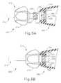
- FIG. 3Bdepicts a perspective view of the surgical instrument of FIG. 3A with the transducer attached and the detachable end effector attached;
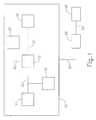
- End effector ( 16 )is coupled to control module ( 12 ) by another electrical connection ( 22 ).
- End effector ( 16 )is configured to perform a desired function of medical device ( 10 ).
- a desired functionmay include cauterizing tissue, ablating tissue, severing tissue, ultrasonically vibrating, stapling tissue, or any other desired task for medical device ( 10 ).
- End effector ( 16 )may thus include an active feature such as an ultrasonic blade, a pair of clamping jaws, a sharp knife, a staple driving assembly, a monopolar RF electrode, a pair of bipolar RF electrodes, a thermal heating element, and/or various other components.
- End effector ( 16 )may also be removable from medical device ( 10 ) for servicing, testing, replacement, or any other purpose as will be apparent to one of ordinary skill in the art in view of the teachings herein and as described with respect to FIGS. 3A-3B below.
- end effector ( 16 )is modular such that medical device ( 10 ) may be used with different kinds of end effectors (e.g., as taught in U.S. Provisional Application Ser. No. 61/410,603, etc.).
- Various other configurations of end effector ( 16 )may be provided for a variety of different functions depending upon the purpose of medical device ( 10 ) as will be apparent to those of ordinary skill in the art in view of the teachings herein.
- other types of components of a medical device ( 10 ) that may receive power from power source ( 14 )will be apparent to those of ordinary skill in the art in view of the teachings herein.
- Medical device ( 10 ) of the present exampleincludes a trigger ( 18 ) and a sensor ( 20 ), though it should be understood that such components are merely optional.
- Trigger ( 18 )is coupled to control module ( 12 ) and power source ( 14 ) by electrical connection ( 22 ).
- Trigger ( 18 )may be configured to selectively provide power from power source ( 14 ) to end effector ( 16 ) (and/or to some other component of medical device ( 10 )) to activate medical device ( 10 ) when performing a procedure.
- Sensor ( 20 )is also coupled to control module ( 12 ) by an electrical connection ( 22 ) and may be configured to provide a variety of information to control module ( 12 ) during a procedure.
- such configurationsmay include sensing impedance in tissue at end effector ( 16 ), sensing a temperature at end effector ( 16 ), determining movement and/or orientation of end effector ( 16 ), or determining the oscillation rate of end effector ( 16 ).
- Data from sensor ( 20 )may be processed by control module ( 12 ) to effect the delivery of power to end effector ( 16 ) (e.g., in a feedback loop, etc.).
- control module ( 12 )may be processed depending upon the purpose of medical device ( 10 ) as will be apparent to those of ordinary skill in the art in view of the teachings herein.
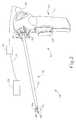
- Surgical instrument ( 50 ) of the present exampleincludes a multi-piece handle assembly ( 60 ), an elongated transmission assembly ( 70 ), and a transducer ( 100 ).
- Transmission assembly ( 70 )is coupled to multi-piece handle assembly ( 60 ) at a proximal end of transmission assembly ( 70 ) and extends distally from multi-piece handle assembly ( 60 ).
- transmission assembly ( 70 )is configured to be an elongated, thin tubular assembly for endoscopic use, but it should be understood that transmission assembly ( 70 ) may alternatively be a short assembly, such as those disclosed in U.S. Pat. Pub. No. 2007/0282333, entitled “Ultrasonic Waveguide and Blade,” published Dec. 6, 2007, and U.S. Pat. Pub. No.
- Lower portion ( 64 ) of multi-piece handle assembly ( 60 )includes a trigger ( 68 ) and is configured to be grasped by a user using a single hand.
- a trigger ( 68 )is configured to be grasped by a user using a single hand.
- FIG. 1One merely exemplary alternative configuration for lower portion ( 64 ) is depicted in FIG. 1 of U.S. Pat. Pub. No. 2011/0015660, entitled “Rotating Transducer Mount for Ultrasonic Surgical Instruments,” published Jan. 20, 2011, now U.S. Pat. No. 8,461,744, issued on Jun. 11, 2013, the disclosure of which is incorporated by reference herein.
- Toggle buttonsmay be located on a distal surface of lower portion ( 64 ) and may be operable to activate transducer ( 100 ) at different operational levels using generator ( 28 ).
- Multi-piece handle assembly ( 60 )may be constructed from a durable plastic (such as polycarbonate or a liquid crystal polymer), ceramics and/or metals or any other suitable material as will be apparent to one of ordinary skill in the art in view of the teachings herein. Still other configurations for multi-piece handle assembly ( 60 ) will be apparent to those of ordinary skill in the art in view of the teachings herein. For instance, instrument ( 50 ) may be operated as part of a robotic system. Other configurations for multi-piece handle assembly ( 60 ) will also be apparent to those of ordinary skill in the art in view of the teachings herein. By way of example only, surgical instrument ( 50 ) may be constructed in accordance with at least some of the teachings of U.S. Pat. No.
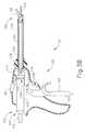
- FIGS. 3A-3Bdepict an alternative version of an ultrasonic instrument ( 101 ) having a reusable transducer and blade assembly ( 102 ) for use in a handle assembly ( 120 ), and a detachable end effector ( 150 ).
- Transducer and blade assembly ( 102 )comprises a transducer ( 104 ) and an elongated blade assembly coupled to transducer ( 104 ) and extending distally from transducer ( 104 ).
- Traducer ( 104 )is operable to convert electrical power from cable ( 112 ) into ultrasonic vibrations at blade ( 116 ).
- casing ( 122 )includes a proximal aperture ( 124 ) configured to receive transducer and blade assembly ( 102 ).
- Trigger ( 125 )is pivotably coupled to casing ( 122 ) and is configured to pivot from an open position to a closed position.
- Trigger ( 125 )is configured to actuate outer sheath ( 138 ) distally via an actuation assembly ( 126 ) when trigger ( 125 ) is in the closed position.
- Toggle buttons ( 128 )comprise buttons operable to selectively activate transducer ( 104 ) at different operational levels using a power source and are operable in accordance with the teachings of U.S. patent application Ser. No. 13/274,805, now U.S. Pat. No. 8,998,939, issued Apr. 7, 2015, which is incorporated by reference herein.
- FIG. 3Ashows casing ( 122 ) with a proximal aperture ( 124 ) configured to receive removable transducer and blade assembly ( 102 ).
- Instrument ( 101 )is capable of accommodating various kinds of transducer and blade assemblies ( 102 ), including those with different types of transducer bodies ( 106 ) and/or those with different types of blades ( 116 ).
- End effector ( 150 )is shown aligned with outer sheath ( 138 ) and inner tubular actuation member ( 140 ), but in a detached position. Initially the user inserts transducer and blade assembly ( 102 ) through proximal aperture ( 124 ).
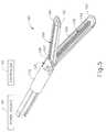
- Assembly ( 102 )is guided through inner tubular actuation member ( 140 ) and out through the distal end of inner tubular actuation member ( 140 ), as shown in FIG. 3B .
- latch member ( 130 )engages notch ( 108 ) to retain transducer and blade assembly ( 102 ) longitudinally within handle assembly ( 120 ).
- Latch member ( 130 ), inner tubular actuation member ( 140 ), and transducer and blade assembly ( 102 )may be constructed and operable in accordance with the teachings of U.S. patent application Ser. No. 13/274,805, issued as U.S. Pat. No. 8,998,939 on Apr. 7, 2015, which is incorporated by reference herein.
- end effector ( 150 ) of the present exampleis then attached to outer sheath ( 138 ) and inner tubular actuation member ( 140 ) as shown in FIG. 3B .
- instrument ( 101 )is capable of accommodating various kinds of end effectors ( 150 ) as will be apparent to those of ordinary skill in the art in view of the teachings herein.
- Outer sheath ( 138 )includes a circumferential groove ( 134 ) into which a portion of actuation assembly ( 126 ) is insertable.
- end effector ( 150 )is coupled to outer sheath ( 138 ) and inner tubular actuation member ( 140 ) prior to the coupling of transducer and blade assembly ( 102 ).
- opposing L-shaped slots ( 148 ) of inner tubular actuation member ( 140 ) and outer sheath ( 138 )are aligned such that opposing bayonet pins ( 154 ) are insertable into longitudinal portions ( 143 ) of each L-shaped slot ( 148 ).
- end effector ( 150 )When bayonet pins ( 154 ) reach the proximal end of longitudinal portions ( 143 ), the user rotates end effector ( 150 ) to rotate bayonet pins ( 154 ) into radial portions ( 144 ) until bayonet pins reach lock portions ( 146 ). With end effector ( 150 ) and transducer and blade assembly ( 102 ) coupled to handle assembly ( 120 ), the user may then use the surgical instrument for a procedure.
- end effector ( 150 ) and/or components thereofmay be removably coupled with transducer and blade assembly ( 102 ) in numerous other ways as will be apparent to those of ordinary skill in the art in view of the teachings herein.
- surgical instrument159
- FIGS. 3-4While some surgical instruments are adapted to use ultrasonic energy to operate on tissue, other surgical instruments, such as surgical instrument ( 159 ), shown in FIGS. 3-4 , can be configured to supply other kinds of energy, such as electrical energy and/or heat energy, to the tissue of a patient.
- energysuch as electrical energy and/or heat energy
- Electrosurgical instrument ( 159 ) of the present exampleincludes a handpiece ( 160 ), a shaft ( 170 ) extending distally from handpiece ( 160 ), and an end effector ( 180 ) disposed at a distal end of shaft ( 170 ).
- Handpiece ( 160 ) of the present exampleincludes a pistol grip ( 162 ), a pivoting trigger ( 164 ), an activation button ( 166 ), and an articulation control ( 168 ).
- Trigger ( 164 )is pivotable toward and away from pistol grip ( 162 ) to selectively actuate end effector ( 180 ) as will be described in greater detail below.
- Activation button ( 166 )is operable to selectively activate RF circuitry that is in communication with end effector ( 180 ), in a manner described in U.S. patent application Ser. No. 13/235,660, published as U.S. Pat. Pub. No. 2012/0078247 on Mar. 29, 2012, and/or various other references that are cited and incorporated by reference herein.
- activation button ( 166 )also serves as a mechanical lockout against trigger ( 164 ), such that trigger ( 164 ) cannot be fully actuated unless button ( 166 ) is being pressed simultaneously. Examples of how such a lockout may be provided are disclosed in one or more of the references cited herein.
- Articulation control ( 168 ) of the present exampleis operable to selectively control articulation section ( 176 ) of shaft ( 170 ) in a manner described in U.S. patent application Ser. No. 13/235,660, published as U.S. Pat. Pub. No. 2012/0078247 on Mar. 29, 2012, which is incorporated by reference herein.
- Shaft ( 170 ) of the present exampleincludes an outer sheath ( 172 ) and an articulation section ( 176 ).
- Articulation section ( 176 )is operable to selectively position end effector ( 180 ) at various angles relative to the longitudinal axis defined by sheath ( 172 ).
- Various examples of forms that articulation section ( 176 ) and other components of shaft ( 170 ) may takeare described in U.S. patent application Ser. No. 13/235,623, entitled “Control Features for Articulating Surgical Device,” filed Sep. 19, 2011, published as U.S. Pat. Pub. No. 2012/0078243 on Mar. 29, 2012, the disclosure of which is incorporated by reference herein.
- shaft ( 170 )is also rotatable about the longitudinal axis defined by sheath ( 172 ), relative to handpiece ( 160 ), via a knob ( 174 ). Such rotation may provide rotation of end effector ( 180 ) and shaft ( 170 ) unitarily.
- knob ( 174 )is operable to rotate end effector ( 180 ) without rotating any portion of shaft ( 170 ) that is proximal of articulation section ( 176 ).
- electrosurgical instrument ( 159 )may include one rotation control that provides rotatability of shaft ( 170 ) and end effector ( 180 ) as a single unit; and another rotation control that provides rotatability of end effector ( 180 ) without rotating any portion of shaft ( 170 ) that is proximal of articulation section ( 176 ).
- Other suitable rotation schemeswill be apparent to those of ordinary skill in the art in view of the teachings herein.
- rotatable featuresmay simply be omitted if desired.
- End effector ( 180 ) of the present examplecomprises a first jaw ( 182 ) and a second jaw ( 184 ).
- second jaw ( 184 )is substantially fixed relative to shaft ( 170 ); while first jaw ( 182 ) pivots relative to shaft ( 170 ), toward and away from second jaw ( 184 ).
- actuatorssuch as rods or cables, etc., may extend through sheath ( 172 ) and be joined with first jaw ( 182 ) at a pivotal coupling ( 183 ), such that longitudinal movement of the actuator rods/cables/etc. through shaft ( 170 ) provides pivoting of first jaw ( 182 ) relative to shaft ( 170 ) and relative to second jaw ( 184 ).
- jaws ( 182 , 184 )may instead have any other suitable kind of movement and may be actuated in any other suitable fashion.
- jaws ( 182 , 184 )may be actuated and thus closed by longitudinal translation of a firing beam ( 195 ), such that actuator rods/cables/etc. may simply be eliminated in some versions.
- first jaw ( 182 )defines a longitudinally extending elongate slot ( 186 ); while second jaw ( 184 ) also defines a longitudinally extending elongate slot ( 148 ).
- first electrode surface ( 190 )presents a first electrode surface ( 190 ); while the underside of second jaw ( 184 ) presents a second electrode surface ( 192 ).
- Electrode surfaces ( 190 , 192 )are in communication with an electrical source ( 198 ) via one or more conductors (not shown) that extend along the length of shaft ( 170 ).
- Electrical source ( 198 )is operable to deliver RF energy to first electrode surface ( 190 ) at a first polarity and to second electrode surface ( 192 ) at a second (opposite) polarity, such that RF current flows between electrode surfaces ( 190 , 192 ) and thereby through tissue captured between jaws ( 182 , 184 ).
- firing beam ( 195 )serves as an electrical conductor that cooperates with electrode surfaces ( 190 , 192 ) (e.g., as a ground return) for delivery of bipolar RF energy captured between jaws ( 182 , 184 ).
- Electrical source ( 198 )may be external to electrosurgical instrument ( 159 ) or may be integral with electrosurgical instrument ( 159 ) (e.g., in handpiece ( 160 ), etc.), as described in one or more references cited herein or otherwise.
- a controller ( 199 )regulates delivery of power from electrical source ( 198 ) to electrode surfaces ( 190 , 192 ).
- Controller ( 199 )may also be external to electrosurgical instrument ( 159 ) or may be integral with electrosurgical instrument ( 159 ) (e.g., in handpiece ( 160 ), etc.), as described in one or more references cited herein or otherwise.
- electrode surfaces ( 190 , 192 )may be provided in a variety of alternative locations, configurations, and relationships.
- first jaw ( 182 )includes a longitudinally extending recess (not shown) adjacent to slot ( 186 ); while the upper side of second jaw ( 184 ) includes a longitudinally extending recess (not shown) adjacent to slot ( 188 ).
- FIG. 4shows the upper side of first jaw ( 182 ) including a plurality of teeth serrations ( 194 ).
- the lower side of second jaw ( 184 )may include complementary serrations that nest with serrations ( 194 ), to enhance gripping of tissue captured between jaws ( 182 , 184 ) without necessarily tearing the tissue.
- Serrations ( 194 )be constructed and operable in accordance with the teachings of U.S. patent application Ser. No. 13/235,660, published as U.S. Pat. Pub. No. 2012/0078247 on Mar. 29, 2012, and/or various other references that are cited and incorporated by reference herein.
- shaft ( 170 ) and end effector ( 180 )are sized and configured to fit through trocars having various inner diameters, such that electrosurgical instrument ( 159 ) is usable in minimally invasive surgery, though of course electrosurgical instrument ( 159 ) could also be used in open procedures if desired.
- Shaft ( 170 ) and end effector ( 180 )may be constructed and operable in accordance with the teachings of U.S. patent application Ser. No. 13/235,660, published as U.S. Pat. Pub. No. 2012/0078247 on Mar. 29, 2012, and/or various other references that are cited and incorporated by reference herein.
- end effector ( 180 )includes one or more sensors (not shown) that are configured to sense a variety of parameters at end effector ( 180 ), including but not limited to temperature of adjacent tissue, electrical resistance or impedance of adjacent tissue, voltage across adjacent tissue, forces exerted on jaws ( 182 , 184 ) by adjacent tissue, etc.
- end effector ( 180 )may include one or more positive temperature coefficient (PTC) thermistor bodies (e.g., PTC polymer, etc.), located adjacent to electrodes ( 190 , 192 ) and/or elsewhere.
- PTCpositive temperature coefficient
- Controller ( 199 )may process such data in a variety of ways.
- controller ( 199 )may modulate or otherwise change the RF energy being delivered to electrode surfaces ( 190 , 192 ), based at least in part on data acquired from one or more sensors at end effector ( 180 ).
- controller ( 199 )may alert the user to one or more conditions via an audio and/or visual feedback device (e.g., speaker, lights, display screen, etc.), based at least in part on data acquired from one or more sensors at end effector ( 180 ).
- an audio and/or visual feedback devicee.g., speaker, lights, display screen, etc.
- some kinds of sensorsneed not necessarily be in communication with controller ( 199 ), and may simply provide a purely localized effect at end effector ( 180 ).
- a PTC thermistor bodies (not shown) at end effector ( 40 )may automatically reduce the energy delivery at electrode surfaces ( 190 , 192 ) as the temperature of the tissue and/or end effector ( 180 ) increases, thereby reducing the likelihood of overheating.
- a PTC thermistor elementis in series with power source ( 198 ) and electrode surface ( 190 , 192 ); and the PTC thermistor provides an increased impedance (reducing flow of current) in response to temperatures exceeding a threshold.
- electrode surfaces ( 190 , 192 )may be used as sensors (e.g., to sense tissue impedance, etc.).
- electrosurgical instrument ( 159 )Various kinds of sensors that may be incorporated into electrosurgical instrument ( 159 ) will be apparent to those of ordinary skill in the art in view of the teachings herein. Similarly various things that can be done with data from sensors, by controller ( 199 ) or otherwise, will be apparent to those of ordinary skill in the art in view of the teachings herein. Other suitable variations for end effector ( 180 ) will also be apparent to those of ordinary skill in the art in view of the teachings herein.
- electrosurgical instrument ( 159 ) of the present exampleincludes a firing beam ( 195 ) that is longitudinally movable along part of the length of end effector ( 180 ).
- Firing beam ( 195 )is coaxially positioned within shaft ( 170 ), extends along the length of shaft ( 170 ), and translates longitudinally within shaft ( 170 ) (including articulation section ( 176 ) in the present example), though it should be understood that firing beam ( 195 ) and shaft ( 170 ) may have any other suitable relationship.
- Firing beam ( 195 )includes a sharp distal blade ( 197 ), an upper flange ( 196 ), and a lower flange (not shown).
- Firing beam ( 195 )may be constructed and operable in accordance with the teachings of U.S. patent application Ser. No. 13/235,660, published as U.S. Pat. Pub. No. 2012/0078247 on Mar. 29, 2012, and/or various other references that are cited and incorporated by reference herein.
- Distal blade ( 197 )extends through slots ( 186 , 188 ) of jaws ( 182 , 184 ), with upper flange ( 196 ) being located above jaw ( 184 ) in a recess (not shown) and the lower flange (not shown) being located below jaw ( 182 ) in a recess (not shown).
- distal blade ( 197 ), upper flange ( 196 ), and the lower flange (not shown)provides an “I-beam” type of cross section at the distal end of firing beam ( 195 ) and may be constructed and operable in accordance with the teachings of U.S. patent application Ser. No. 13/235,660, published as U.S. Pat. Pub. No. 2012/0078247 on Mar. 29, 2012, and/or various other references that are cited and incorporated by reference herein.
- Distal blade ( 197 )is substantially sharp, such that distal blade will readily sever tissue that is captured between jaws ( 182 , 184 ). Distal blade ( 197 ) is also electrically grounded in the present example, providing a return path for RF energy as described elsewhere herein. In some other versions, distal blade ( 197 ) serves as an active electrode. In addition or in the alternative, distal blade ( 197 ) may be selectively energized with ultrasonic energy (e.g., harmonic vibrations at approximately 55.5 kHz, etc.).
- ultrasonic energye.g., harmonic vibrations at approximately 55.5 kHz, etc.
- firing beam ( 195 )provides closure of jaws ( 182 , 184 ) as firing beam ( 195 ) is advanced distally.
- flange ( 196 )urges jaw ( 184 ) pivotally toward jaw ( 182 ) as firing beam ( 195 ) is advanced from a proximal position to a distal position, by bearing against a recess (not shown) formed in jaw ( 184 ).
- This closing effect on jaws ( 182 , 184 ) by firing beam ( 195 )may occur before distal blade ( 197 ) reaches tissue captured between jaws ( 182 , 184 ).
- firing beam ( 195 )may reduce the force required to squeeze grip ( 164 ) to actuate firing beam ( 195 ) through a full firing stroke.
- firing beam ( 195 )may have already overcome an initial resistance required to substantially close jaws ( 182 , 184 ) on tissue before encountering resistance from the tissue captured between jaws ( 182 , 184 ).
- any other suitable stagingmay be provided.
- flange ( 196 )is configured to cam against a ramp feature at the proximal end of jaw ( 184 ) to open jaw ( 182 ) when firing beam ( 195 ) is retracted to a proximal position and to hold jaw ( 182 ) open when firing beam ( 195 ) remains at the proximal position.
- This camming capabilitymay facilitate use of end effector ( 180 ) to separate layers of tissue, to perform blunt dissections, etc., by forcing jaws ( 182 , 184 ) apart from a closed position.
- jaws ( 182 , 184 )are resiliently biased to an open position by a spring or other type of resilient feature.
- jaws ( 182 , 184 )close or open as firing beam ( 195 ) is translated in the present example
- other versionsmay provide independent movement of jaws ( 182 , 184 ) and firing beam ( 195 ).
- one or more cables, rods, beams, or other featuresmay extend through shaft ( 170 ) to selectively actuate jaws ( 182 , 184 ) independently of firing beam ( 195 ).
- Such jaw ( 182 , 184 ) actuation featuresmay be separately controlled by a dedicated feature of handpiece ( 160 ).
- jaw actuation featuresmay be controlled by trigger ( 164 ) in addition to having trigger ( 164 ) control firing beam ( 195 ).
- firing beam ( 195 )may be resiliently biased to a proximal position, such that firing beam ( 195 ) retracts proximally when a user relaxes their grip on trigger ( 164 ).
- end effector ( 180 )is inserted into a patient via a trocar.
- Articulation section ( 176 )is substantially straight when end effector ( 180 ) and part of shaft ( 170 ) are inserted through the trocar.
- Articulation control ( 168 )may then be manipulated to pivot or flex articulation section ( 176 ) of shaft ( 170 ) in order to position end effector ( 180 ) at a desired position and orientation relative to an anatomical structure within the patient.
- Two layers of tissue of the anatomical structureare then captured between jaws ( 182 , 184 ) by squeezing trigger ( 164 ) toward pistol grip ( 162 ).
- Such layers of tissuemay be part of the same natural lumen defining anatomical structure (e.g., blood vessel, portion of gastrointestinal tract, portion of reproductive system, etc.) in a patient.
- one tissue layermay comprise the top portion of a blood vessel while the other tissue layer may comprise the bottom portion of the blood vessel, along the same region of length of the blood vessel (e.g., such that the fluid path through the blood vessel before use of electrosurgical instrument ( 159 ) is perpendicular to the longitudinal axis defined by end effector ( 180 ), etc.).
- the lengths of jaws ( 182 , 184 )may be oriented perpendicular to (or at least generally transverse to) the length of the blood vessel.
- flanges ( 162 , 166 )cammingly act to pivot jaw ( 182 ) toward jaw ( 184 ) when firing beam ( 195 ) is actuated distally by squeezing trigger ( 164 ) toward pistol grip ( 162 ).
- firing beam ( 195 )continues to advance distally by the user squeezing trigger ( 164 ) toward pistol grip ( 162 ).
- distal blade ( 197 )simultaneously severs the clamped tissue layers, resulting in separated upper layer portions being apposed with respective separated lower layer portions. In some versions, this results in a blood vessel being cut in a direction that is generally transverse to the length of the blood vessel.
- upper flange ( 162 ) and the lower flange (not shown) immediately above and below jaws ( 182 , 184 ), respectively,may help keep jaws ( 182 , 184 ) in a closed and tightly clamping position.
- flanges ( 162 , 166 )may help maintain a significantly compressive force between jaws ( 182 , 184 ).
- electrode surfaces ( 190 , 192 )are activated with bipolar RF energy by the user depressing activation button ( 166 ).
- electrodes ( 190 , 192 )are selectively coupled with power source ( 198 ) (e.g., by the user depressing button ( 166 ), etc.) such that electrode surfaces ( 190 , 192 ) of jaws ( 182 , 184 ) are activated with a common first polarity while firing beam ( 195 ) is activated at a second polarity that is opposite to the first polarity.
- a bipolar RF currentflows between firing beam ( 195 ) and electrode surfaces ( 190 , 192 ) of jaws ( 182 , 184 ), through the compressed regions of severed tissue layer portions.
- electrode surface ( 190 )has one polarity while electrode surface ( 192 ) and firing beam ( 195 ) both have the other polarity.
- bipolar RF energy delivered by power source ( 198 )ultimately thermally welds the tissue layer portions on one side of firing beam ( 195 ) together and the tissue layer portions on the other side of firing beam ( 195 ) together.
- the heat generated by activated electrode surfaces ( 190 , 192 )can denature the collagen within the tissue layer portions and, in cooperation with clamping pressure provided by jaws ( 182 , 184 ), the denatured collagen can form a seal within the tissue layer portions.
- the severed ends of the natural lumen defining anatomical structureare hemostatically sealed shut, such that the severed ends will not leak bodily fluids.
- electrode surfaces ( 190 , 192 )may be activated with bipolar RF energy before firing beam ( 195 ) even begins to translate distally and thus before the tissue is even severed. For instance, such timing may be provided in versions where button ( 166 ) serves as a mechanical lockout relative to trigger ( 164 ) in addition to serving as a switch between power source ( 198 ) and electrode surfaces ( 190 , 192 ).
- end effectors16 , 80 , 150 , 180
- handle assembly60 , 120 , 160
- a large amount of tissuemay need to be cut, requiring different length end effectors ( 80 , 150 , 180 ) and/or shafts for transmission assemblies ( 70 , 102 , 170 ).
- Such interchangeable shafts and/or end effectors ( 80 , 150 , 180 )may permit a common handle assembly ( 60 , 120 , 160 ) to be used for various surgical procedures (e.g., short shafts for open surgery, long shafts for minimally invasive laparoscopic surgery, etc.).
- changing out the shafts and/or the end effectors ( 80 , 150 , 180 ) while reusing the same handle assembly ( 60 , 120 , 160 )may be more time and/or cost effective than using a new surgical instrument ( 50 , 101 , 159 ) with the different length shaft.
- such shafts and/or end effectors ( 80 , 150 , 180 )may include color codes to distinguish the various lengths and/or types.
- the handle assembly ( 60 , 120 , 160 )may be configured to employ different types of end effectors, for instance, the handle assembly ( 60 , 120 , 160 ) may include components to operate an ultrasonic end effector ( 80 , 150 ) and/or an RF end effector ( 180 ).
- the handle assembly ( 60 , 120 , 160 )may include components to operate an ultrasonic end effector ( 80 , 150 ) and/or an RF end effector ( 180 ).
- changing the shafts and end effectors ( 80 , 150 , 180 ) with a common handle assembly ( 60 , 120 , 160 )may conserve time and/or costs.
- various coupling mechanisms for coupling the modular shafts to the handle assemblies ( 60 , 120 , 160 )are described below.
- transducer ( 100 )may be integral with the shaft and end effector ( 80 ), and may thus be selectively coupled with handle assembly ( 60 ).
- transducer ( 100 )may be integral with handle assembly ( 60 ) such that the shaft and end effector ( 80 ) are selectively coupled with transducer ( 100 ) when the shaft and end effector ( 80 ) are selectively coupled with handle assembly ( 60 ).
- An exemplary coupling mechanism ( 200 )comprises a threaded slip nut ( 230 ) disposed about a shaft ( 220 ) of an exemplary end effector assembly ( 210 ), shown in FIGS. 6A-6B .
- end effector assembly ( 210 )comprises a transmission assembly ( 212 ), a rotation knob ( 214 ), and a shaft ( 220 ) extending proximally relative to rotation knob ( 214 ).
- rotation knob ( 214 )is merely optional and may be omitted.
- Rotation knob ( 214 )is operable to rotate transmission assembly ( 212 ) relative to a handle assembly ( 240 ) and/or shaft ( 220 ).
- An end effector(not shown) is coupled to a distal end of transmission assembly ( 212 ).
- the end effectormay include an ultrasonic end effector ( 80 , 150 ), an RF end effector ( 180 ), and/or any other end effector or combination of end effectors as will be apparent to one of ordinary skill in the art in view of the teachings herein.
- Transmission assembly ( 212 )is operable to communicate energy (e.g., ultrasonic vibrations, RF energy, and/or mechanical motion/force, etc.) from a source proximal to transmission assembly ( 212 ) to an end effector at the distal end of transmission assembly ( 212 ).
- an axial bore (not shown) through shaft ( 220 )may permit mechanical coupling of transmission assembly ( 212 ) through shaft ( 220 ) to components within handle assembly ( 240 ), which may be configured in a similar manner to multi-piece handle assembly ( 60 ) described above.
- the axial boremay permit a portion of transmission assembly ( 212 ) to extend at least partially through shaft ( 220 ).
- Transmission assembly ( 212 )may include an inner slip ring connector that is electrically coupleable to a complementary slip ring connector on the interior of shaft ( 220 ) such that an electrical coupling from handle assembly ( 240 ) may be made to the end effector.
- a fluid couplingmay also be made via the bore through shaft ( 220 ) and/or elsewhere on end effector assembly ( 210 ).
- a threaded slip nut ( 230 )is slidably disposed about shaft ( 220 ).
- Threaded slip nut ( 230 )includes a keyway ( 232 ) (shown in phantom) at a proximal end of threaded slip nut ( 230 ).
- keyway ( 232 )may alternatively be located on a distal end of threaded slip nut ( 230 ).
- Keyway ( 232 ) of the present exampleonly partially extends through threaded slip nut ( 230 ), though keyway ( 232 ) may alternatively extend completely through threaded slip nut ( 230 ). As shown in FIGS.
- keyway ( 232 )is configured to receive a keyed portion ( 222 ) of shaft ( 220 ).
- keyed portion ( 222 ) of shaft ( 220 )is located near a proximal end of shaft ( 220 ) and extends outwardly from shaft ( 220 ), though it should be understood that keyed portion ( 222 ) may alternatively be located distally near rotation knob ( 214 ) or at a midpoint of shaft ( 220 ).
- keyed portion ( 222 )may be slidable relative to shaft ( 220 ), such as by actuation of a slider to slide keyed portion ( 222 ) into keyway ( 232 ).
- Shaft ( 220 )further comprises a proximal flange ( 224 ) located on the proximal end of shaft ( 220 ) and sized to prevent threaded slip nut ( 230 ) from sliding proximally off of shaft ( 220 ).
- keyed portion ( 222 )is insertable into keyway ( 232 ) when a user desires to thread threaded slip nut ( 230 ) into internal threading ( 250 ) of handle assembly ( 240 ).
- Threaded slip nut ( 230 ) of the present examplemay then be slid distally on shaft ( 220 ) to disengage keyed portion ( 222 ) from keyway ( 232 ), thereby permitting shaft ( 220 ), rotation knob ( 214 ), and/or transmission assembly ( 212 ) to rotate freely relative to threaded slip nut ( 230 ) and/or handle assembly ( 240 ).
- threaded slip nut ( 230 )may be slidably disposed on an inner tube, such as an inner tubular actuating member described above.
- threaded slip nut ( 230 )may be configured to thread into a yoke, such as trigger yoke ( 185 ) described in U.S. Pat. Pub. No. 2011/0015660, entitled “Rotating Transducer Mount for Ultrasonic Surgical Instruments,” published Jan. 20, 2011, now U.S. Pat. No. 8,461,744 issued on Jun. 11, 2013, the disclosure of which is incorporated by reference herein.
- a bladesuch as blade ( 82 ) described above, may be coupled to a transducer, such as transducer ( 100 ) described above.
- the inner tubular actuating membermay be actuated via the coupling of threaded slip nut ( 230 ) to the yoke. Accordingly, a clamp arm, such as clamp arm ( 84 ) described above, may be operable to clamp tissue against the blade.
- handle assembly ( 240 )is shown having a distal aperture ( 242 ) formed within a casing ( 244 ) and configured to receive shaft ( 220 ) and threaded slip nut ( 230 ) of end effector assembly ( 210 ).
- Handle assembly ( 240 )may further be configured in accordance with at least some of the teachings for multi-piece handle assembly ( 60 ), for handle assembly ( 152 ), of U.S. Pat. Pub. No. 2011/0015660, entitled “Rotating Transducer Mount for Ultrasonic Surgical Instruments,” published Jan. 20, 2011, now U.S. Pat. No. 8,461,744 issued on Jun. 11, 2013, or of U.S. Pat. No.
- handle assembly ( 240 )includes a member ( 248 ) having internal threading ( 250 ) disposed about a member aperture ( 252 ). Internal threading ( 250 ) and threaded slip nut ( 230 ) are configured to thread together to secure end effector assembly ( 210 ) to handle assembly ( 240 ).
- threaded slip nut ( 230 ) of the present exampleis slid proximally such that keyed portion ( 222 ) of shaft ( 220 ) engages keyway ( 232 ) of threaded slip nut ( 230 ).
- keyed portion ( 222 ) of shaft ( 220 )engages keyway ( 232 ) of threaded slip nut ( 230 ).
- a userthen threads threaded slip nut ( 230 ) into internal threading ( 250 ) of handle assembly ( 240 ).
- an L-shaped spacer toolmay be used to urge threaded slip nut ( 230 ) proximally on shaft ( 220 ) against flange ( 224 ) while the user threads threaded slip nut ( 230 ) into internal threading ( 250 ).
- a usermay manually urge threaded slip nut ( 230 ) proximally.
- a slideras noted above, may engage a portion of threaded slip nut ( 230 ) to urge threaded slip nut ( 230 ) proximally.
- a springmay be disposed about shaft ( 220 ) distally of slip nut ( 230 ) and proximally of rotation knob ( 214 ), thereby biasing slip nut ( 230 ) proximally such that keyway ( 232 ) is engaged with keyed portion ( 222 ).
- end effector assembly ( 210 )When the user desires to rotate end effector assembly ( 210 ), the user grasps rotation knob ( 214 ) and pushes end effector assembly ( 210 ) proximally until keyed portion ( 222 ) disengages from keyway ( 232 ).
- end effector assembly ( 210 )is slid proximally to disengage keyed portion ( 222 ) from keyway ( 232 ).
- End effector assembly ( 210 )may be manually slid distally or, in one alternative, a spring (not shown) located between flange ( 224 ) and threaded slip nut ( 230 ) may urge end effector assembly ( 210 ) distally.
- shaft ( 220 ) of end effector assembly ( 210 )may be threaded onto a horn of a transducer, such as transducer ( 100 ) described above. Such threading may occur prior to, contemporaneously with, or after the threading of threaded slip nut ( 230 ) into internal threading ( 250 ).
- shaft ( 220 )may be coupled to one or more electrical connectors (not shown) to couple the end effector to a power source. As shown in FIG.
- end effector assembly ( 210 )is effectively longitudinally secured to handle assembly ( 240 ) while permitting rotational movement of shaft ( 220 ), rotation knob ( 214 ), and/or transmission assembly ( 212 ). A user may then use the assembled surgical instrument for a procedure.
- the userdesires to decouple end effector assembly ( 210 ) from handle assembly ( 240 )
- the userpulls end effector assembly ( 210 ) distally until keyed portion ( 222 ) of shaft ( 220 ) engages keyway ( 232 ) of threaded slip nut ( 230 ).
- the L-shaped spacer toolmay be wedged between threaded slip nut ( 230 ) and rotation knob ( 214 ) to urge threaded slip nut ( 230 ) proximally.
- the usermay then unscrew threaded slip nut ( 230 ) from internal threading ( 250 ), thereby decoupling end effector assembly ( 210 ) from handle assembly ( 240 ).
- a usermay then couple a new end effector assembly ( 210 ) to handle assembly ( 240 ).
- threaded slip nut ( 230 )may be located between flange ( 224 ) and another annular flange (not shown) of shaft ( 220 ).
- keyed portion ( 222 )may be actuated radially outward from an initial position within a recess (not shown) of shaft ( 220 ) to a position where keyed portion ( 222 ) engages keyway ( 232 ) of threaded slip nut ( 230 ).
- keyed portion ( 222 )may be actuated by a cam member coupled to a slider located on transmission assembly ( 212 ) and/or rotation knob ( 214 ).
- a cam membercoupled to a slider located on transmission assembly ( 212 ) and/or rotation knob ( 214 ).
- various other electrical and/or mechanical coupling mechanisms and/or featuresmay be used to substitute coupling mechanism ( 200 ), to modify coupling mechanism ( 200 ), or to combine with coupling mechanism ( 200 ).
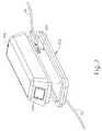
- a data modulesuch as smart cartridge ( 300 ) shown in FIG. 7
- Cartridge ( 300 )may be similar to cartridge ( 26 ) shown in FIG. 1 and, similarly, be positioned between instrument ( 10 , 24 , 101 ) and generator ( 28 ), and connected to instrument ( 10 , 24 , 101 ) and generator ( 28 ) via cable ( 30 ).
- Cartridge ( 300 )may be programmed to provide unique operating parameters as described above to a single use blade of end effector ( 16 , 80 , 150 , 180 ) on a resterilizable handle ( 60 , 120 , 160 ), for instance.
- one cartridge ( 300 )may be associated with one or more types of ultrasonic end effectors; while another cartridge ( 300 ) may be associated with one or more types of RF electrosurgical end effectors.
- the operating parametersmay set, for instance, a range for or a maximum voltage to apply across adjacent tissue, and/or a range of or maximum forces to exert on jaws of end effectors ( 16 , 80 , 150 , 180 ).
- cartridge ( 300 )By allowing for cartridge ( 300 ) to transmit the unique operating parameters rather than utilizing a transducer or generator for such transmission, a greater array of removable end effectors ( 16 , 80 , 150 , 180 ) may be programmed and the cartridge may be used alongside one or more transducers, generators, and resterilizable handles (not shown, 60 , 120 , 160 ).
- the same “universal” generator, transducer, handle assembly, and/or other electronic/electrical componentsmay be used for various end effector types, various surgical modalities (e.g., ultrasonic surgical modality, RF electrosurgical modality, powered stapling modality, etc.), and various surgical procedures (e.g., plastic surgery, orthopedic surgery, etc.) based on parameters established by cartridge ( 300 ).
- various surgical modalitiese.g., ultrasonic surgical modality, RF electrosurgical modality, powered stapling modality, etc.
- various surgical procedurese.g., plastic surgery, orthopedic surgery, etc.
- FIG. 7shows a docking station ( 302 ) including pocket ( 304 ).
- Pocket ( 304 )is sized and shaped to receive an underside of cartridge ( 300 ).
- Pocket ( 304 )includes connection portions or contacts ( 306 ), into which mutual connection prongs (not shown) from the underside of cartridge ( 300 ) connect.
- cartridge ( 300 )may have an inductive coupling with docking station ( 302 ) in addition to or in lieu of using contacts ( 306 ) for electrical communication.
- Cartridge ( 300 )may be removably secured to docking station ( 302 ) via a magnetic connection, latches, clips, clamps, straps, and/or otherwise.
- Cartridge ( 300 )include a memory chip, such as a read-only-memory (ROM) chip, that is capable of storing information such as desired procedural operating parameters, as described above.
- the chipmay be an Electrically Erasable Programmable Read-Only Memory (EEPROM) chip, which may be used with a surgical instrument and/or computer as a type of non-volatile memory that stores data even when power is removed, such as date regarding device configuration and operating parameters.
- Docking station ( 302 )may be an injection molded component that is sterilizable pre-use in a surgical procedure.
- the underside of docking station ( 302 )may include a recessed opening into which to receive a portion of a drape covering a patient, so to secure docking station ( 302 ) within the vicinity of the patient during a surgical procedure. Additionally or alternatively, the underside of docking station ( 302 ) may comprise an adhesive to permit the attachment of docking station ( 302 ) to a patient-covering drape or other component in the vicinity of the patient during a procedure.
- Cartridge ( 300 )may be pre-programmed in a kit containing cartridge ( 300 ) and a unique blade and/or other component for a removable end effector ( 80 , 140 ). While the example below references instrument ( 50 ) of FIG. 2 , a similar use may occur with instrument ( 159 ) of FIG. 4 .
- a program module within cartridge ( 300 )which may comprise, for example, a memory chip, is programmed with a unique set of operating parameters associated with a particular type of end effector and/or a particular type of surgical procedure.
- a resterilizable handle ( 60 )is attached to a generator ( 28 ) via one or more cables ( 30 ).
- Cartridge ( 300 )attaches to a first end of a first cable ( 30 ), a second end of which attaches to generator ( 28 ). Cartridge ( 300 ) also attached to a first end of a second cable ( 30 ), a second end of which attaches to instrument ( 50 ).
- the unique, single use blademay be loaded to end effector ( 80 ) of handle ( 60 ).
- a single use shaft ( 72 ) and end effector ( 80 ) assemblymay be attached to handle ( 60 ).
- the removable shaft and end effector assemblymay be attached to and tightened against transducer ( 100 ).
- Generator ( 28 )is then powered to send a signal to cartridge ( 300 ) to load the operating parameters data into the programmable, reusable handle ( 60 ).
- Instrument ( 50 )may be used in a surgical procedure with the specific set of loaded operating parameters, as described above.
- cartridge ( 300 )may simply drive transducer ( 100 ), end effector ( 80 ), and/or other components in accordance with the parameters stored in cartridge ( 300 ), without having to load those parameters into another component.
- handle ( 60 )does not necessarily need to be programmable.
- Cartridge ( 300 )may integrally including program module ( 308 ) that includes a specific set of operating parameters and may connect to a receiver such as docking station ( 302 ) disposed between handle ( 60 ) of instrument ( 50 ) and generator ( 28 ), as described above and shown in FIGS. 1 and 7 .
- program module ( 308 )that includes a specific set of operating parameters and may connect to a receiver such as docking station ( 302 ) disposed between handle ( 60 ) of instrument ( 50 ) and generator ( 28 ), as described above and shown in FIGS. 1 and 7 .
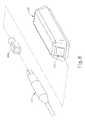
- program module ( 308 )may be a separate component receivable into cartridge ( 300 ), as shown in FIG. 8 .
- Cable ( 30 )connected at one end to handle ( 60 ) for instance, connects at a second end to program module ( 308 ), which is then received into reception aperture ( 310 ) of cartridge ( 300 ).
- Program module ( 308 )may include a magnetic feature to allow for a magnetic connection to cartridge ( 300 ).
- An aperture on an opposite surface of cartridge ( 300 )may connect to a separate cable ( 30 ) leading to generator ( 28 ), for example; or such a cable may be integral with cartridge ( 300 ).
- cartridge ( 300 )may couple only with a surgical instrument and not to a generator.
- Cartridge ( 300 )may utilize alternative means of power, such as battery power from the device or from within cartridge ( 300 ), to transmit operating parameter information to the respective device.
- FIG. 9shows a male portion of cable ( 30 ) that is receivable into a female portion of program module ( 308 ), the opposite type of connection is possible where a female portion of cable ( 30 ) is receivable into a male portion of program module ( 308 ). Similarly, while a male portion of program module ( 308 ) is shown as receivable within female port ( 312 ), the opposite type of connection is possible FIG. 9 also shows generator ( 28 ) resting on table ( 314 ) and receiving power from power source ( 316 ) via conduit ( 318 ), though any other suitable positioning or arrangement may be used.
- cartridge ( 300 ) and program module ( 308 )is loaded ( 500 ) with one or more operating parameters such that the one or more operating parameters are stored within program module ( 308 ).
- Loaded cartridge ( 300 )is then connected ( 502 ) to instrument ( 50 ) at a first end of cartridge ( 300 ).
- Cartridge ( 300 )is connected ( 504 ) to generator ( 28 ) at a second end of cartridge ( 300 ).
- Instrument ( 50 )is loaded ( 506 ) with the operating parameters transmitted from cartridge ( 300 ).
- the EEPROM chipdescribed above, could be embedded in instrument ( 50 ) and include information specifying a maximum current set portion for generator ( 28 ).
- the specified current set pointmay be used to provide an enhanced, substantially optimum performance for a prospective surgeon-user group.
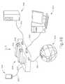
- FIG. 13shows a schematic view of an example of transmission of information to device ( 10 ) contained within a sterilized packaging unit ( 520 ).
- Device ( 10 )includes an information receiving device such as radiofrequency (RF) receiver ( 522 ) which may be included within or separate from sensor ( 20 ) of FIG. 1 .
- RFradiofrequency
- Device ( 10 ) of this exampleis a multi-function surgical instrument that is operable to perform various surgical modalities and/or to be used in various kinds of surgical procedures, depending on operational parameters used to program device ( 10 ).
- Station ( 526 )wirelessly transmits information from programmer ( 524 ) as shown by arrow (A) to RF receiver ( 522 ) of device ( 10 ).
- Informationmay be transmitted via means such as, for example, the use of RF wireless (e.g., using the protocol of Bluetooth®, a registered trademark of Bluetooth Sig, Inc. of Kirkland, Wash.), and/or infrared technologies.
- Station ( 526 )may receive unit ( 520 ) or may wirelessly transmit information to a unit ( 526 ) when it is a certain distance away from station ( 526 ), for instance; or upon receiving a signal to transmit information to one or more devices ( 10 ) within a specified vicinity or distance.
- Programmer ( 524 )submits a selected portion of that information to label generator ( 528 ).
- FIG. 14shows an exemplary process associated with the use of programmer ( 524 ) in FIG. 13 .
- RF receiver ( 522 )is incorporated ( 530 ) into device ( 10 ).
- Device ( 10 )is received ( 532 ) into a packaging unit ( 520 ) that is to be sealed and sterilized.
- Unit ( 520 )is sealed and sterilized, and sent to a hospital or other site where device ( 10 ) will eventually be used.
- programmer ( 524 )is used ( 534 ) to supply operating parameters to RF docking station ( 526 ), as described above.
- the operating parameter informationis transmitted ( 536 ) from RF docking station ( 526 ) to RF receiver ( 522 ) and to label generator ( 528 ), as described above.
- a label(not shown) is prepared ( 538 ) or printed to show a portion of or all of the information transmitted to device ( 10 ).
- the labelmay indicate that device ( 10 ) is programmed for use in a plastic surgery procedure.
- the labelis then applied ( 540 ) to unit ( 520 ) containing device ( 10 ) such that a user may know what operating parameters have been loaded to device ( 10 ).
- programmer ( 524 )enables surgeons and other hospital personnel to easily program a relatively “universal’ instrument ( 10 ) on an ad hoc basis based on present surgical needs and/or based on a particular surgeon's preferences.
- the handle assemblies and/or end effectorsmay be reusable, autoclavable, and/or disposable.
- the foregoing end effectorsmay be disposable while the handle assemblies are reuseable and/or autoclavable.
- the internal power sourcesmay be rechargeable.
- the handle assembliesmay be recharged using a plug in recharge, by removing and recharging the batteries, by induction, and/or by any other method as will be apparent to one of ordinary skill in the art in view of the teachings herein.
- alignment features or guidesmay be included to aid in the alignment and coupling of the end effectors with handle assemblies. Such guides may help prevent damage to the end effector and/or handle assembly during the assembly of the surgical instrument.
- Embodiments of the present inventionhave application in conventional endoscopic and open surgical instrumentation as well as application in robotic-assisted surgery.
- those of ordinary skill in the artwill recognize that various teaching herein may be readily combined with various teachings of U.S. Pat. No. 6,783,524, entitled “Robotic Surgical Tool with Ultrasound Cauterizing and Cutting Instrument,” issued Aug. 31, 2004, the disclosure of which is incorporated by reference herein.
- a new or used instrumentmay be obtained and if necessary cleaned.
- the instrumentmay then be sterilized.
- the instrumentis placed in a closed and sealed container, such as a plastic or TYVEK bag.
- the container and instrumentmay then be placed in a field of radiation that can penetrate the container, such as gamma radiation, x-rays, or high-energy electrons.
- the radiationmay kill bacteria on the instrument and in the container.
- the sterilized instrumentmay then be stored in the sterile container.
- the sealed containermay keep the instrument sterile until it is opened in a medical facility.
- a devicemay also be sterilized using any other technique known in the art, including but not limited to beta or gamma radiation, ethylene oxide, or steam.
- Embodiments of the devices disclosed hereincan be reconditioned for reuse after at least one use.
- Reconditioningmay include any combination of the steps of disassembly of the device, followed by cleaning or replacement of particular pieces, and subsequent reassembly.
- embodiments of the devices disclosed hereinmay be disassembled, and any number of the particular pieces or parts of the devices may be selectively replaced or removed in any combination.
- embodiments of the devicesmay be reassembled for subsequent use either at a reconditioning facility, or by a surgical team immediately prior to a surgical procedure.
Landscapes
- Health & Medical Sciences (AREA)
- Surgery (AREA)
- Life Sciences & Earth Sciences (AREA)
- Engineering & Computer Science (AREA)
- Molecular Biology (AREA)
- Public Health (AREA)
- Veterinary Medicine (AREA)
- Biomedical Technology (AREA)
- Heart & Thoracic Surgery (AREA)
- Medical Informatics (AREA)
- Nuclear Medicine, Radiotherapy & Molecular Imaging (AREA)
- Animal Behavior & Ethology (AREA)
- General Health & Medical Sciences (AREA)
- Physics & Mathematics (AREA)
- Pathology (AREA)
- Oral & Maxillofacial Surgery (AREA)
- Plasma & Fusion (AREA)
- Otolaryngology (AREA)
- Dentistry (AREA)
- Mechanical Engineering (AREA)
- Electromagnetism (AREA)
- Surgical Instruments (AREA)
Abstract
Description
Claims (19)
Priority Applications (6)
| Application Number | Priority Date | Filing Date | Title |
|---|---|---|---|
| US13/426,760US9364249B2 (en) | 2012-03-22 | 2012-03-22 | Method and apparatus for programming modular surgical instrument |
| AU2013201052AAU2013201052B2 (en) | 2012-03-22 | 2013-02-21 | Method and apparatus for programming modular surgical instrument |
| CA2809424ACA2809424C (en) | 2012-03-22 | 2013-03-12 | Method and apparatus for programming modular surgical instrument |
| EP13160483.7AEP2641552B1 (en) | 2012-03-22 | 2013-03-21 | Apparatus for programming modular surgical instrument |
| JP2013057917AJP6279221B2 (en) | 2012-03-22 | 2013-03-21 | Method and apparatus for programming a modular surgical instrument |
| CN201310093887.9ACN103315807B (en) | 2012-03-22 | 2013-03-22 | For the method and apparatus of programming module surgical instruments |
Applications Claiming Priority (1)
| Application Number | Priority Date | Filing Date | Title |
|---|---|---|---|
| US13/426,760US9364249B2 (en) | 2012-03-22 | 2012-03-22 | Method and apparatus for programming modular surgical instrument |
Publications (2)
| Publication Number | Publication Date |
|---|---|
| US20130253499A1 US20130253499A1 (en) | 2013-09-26 |
| US9364249B2true US9364249B2 (en) | 2016-06-14 |
Family
ID=47997097
Family Applications (1)
| Application Number | Title | Priority Date | Filing Date |
|---|---|---|---|
| US13/426,760Active2034-11-16US9364249B2 (en) | 2012-03-22 | 2012-03-22 | Method and apparatus for programming modular surgical instrument |
Country Status (6)
| Country | Link |
|---|---|
| US (1) | US9364249B2 (en) |
| EP (1) | EP2641552B1 (en) |
| JP (1) | JP6279221B2 (en) |
| CN (1) | CN103315807B (en) |
| AU (1) | AU2013201052B2 (en) |
| CA (1) | CA2809424C (en) |
Cited By (138)
| Publication number | Priority date | Publication date | Assignee | Title |
|---|---|---|---|---|
| US10327798B2 (en) | 2012-05-31 | 2019-06-25 | Ethicon Llc | Surgical instrument with orientation sensing |
| US10695081B2 (en) | 2017-12-28 | 2020-06-30 | Ethicon Llc | Controlling a surgical instrument according to sensed closure parameters |
| US10755813B2 (en) | 2017-12-28 | 2020-08-25 | Ethicon Llc | Communication of smoke evacuation system parameters to hub or cloud in smoke evacuation module for interactive surgical platform |
| US10758310B2 (en) | 2017-12-28 | 2020-09-01 | Ethicon Llc | Wireless pairing of a surgical device with another device within a sterile surgical field based on the usage and situational awareness of devices |
| US10849697B2 (en) | 2017-12-28 | 2020-12-01 | Ethicon Llc | Cloud interface for coupled surgical devices |
| US10892995B2 (en) | 2017-12-28 | 2021-01-12 | Ethicon Llc | Surgical network determination of prioritization of communication, interaction, or processing based on system or device needs |
| US10892899B2 (en) | 2017-12-28 | 2021-01-12 | Ethicon Llc | Self describing data packets generated at an issuing instrument |
| US10898622B2 (en) | 2017-12-28 | 2021-01-26 | Ethicon Llc | Surgical evacuation system with a communication circuit for communication between a filter and a smoke evacuation device |
| US10932806B2 (en) | 2017-10-30 | 2021-03-02 | Ethicon Llc | Reactive algorithm for surgical system |
| US10932872B2 (en) | 2017-12-28 | 2021-03-02 | Ethicon Llc | Cloud-based medical analytics for linking of local usage trends with the resource acquisition behaviors of larger data set |
| US10944728B2 (en) | 2017-12-28 | 2021-03-09 | Ethicon Llc | Interactive surgical systems with encrypted communication capabilities |
| US10966791B2 (en) | 2017-12-28 | 2021-04-06 | Ethicon Llc | Cloud-based medical analytics for medical facility segmented individualization of instrument function |
| US10973520B2 (en) | 2018-03-28 | 2021-04-13 | Ethicon Llc | Surgical staple cartridge with firing member driven camming assembly that has an onboard tissue cutting feature |
| US10987178B2 (en) | 2017-12-28 | 2021-04-27 | Ethicon Llc | Surgical hub control arrangements |
| US11013563B2 (en) | 2017-12-28 | 2021-05-25 | Ethicon Llc | Drive arrangements for robot-assisted surgical platforms |
| US11026687B2 (en) | 2017-10-30 | 2021-06-08 | Cilag Gmbh International | Clip applier comprising clip advancing systems |
| US11026751B2 (en) | 2017-12-28 | 2021-06-08 | Cilag Gmbh International | Display of alignment of staple cartridge to prior linear staple line |
| US11056244B2 (en) | 2017-12-28 | 2021-07-06 | Cilag Gmbh International | Automated data scaling, alignment, and organizing based on predefined parameters within surgical networks |
| US11051876B2 (en) | 2017-12-28 | 2021-07-06 | Cilag Gmbh International | Surgical evacuation flow paths |
| US11058498B2 (en) | 2017-12-28 | 2021-07-13 | Cilag Gmbh International | Cooperative surgical actions for robot-assisted surgical platforms |
| US11069012B2 (en) | 2017-12-28 | 2021-07-20 | Cilag Gmbh International | Interactive surgical systems with condition handling of devices and data capabilities |
| US11076921B2 (en) | 2017-12-28 | 2021-08-03 | Cilag Gmbh International | Adaptive control program updates for surgical hubs |
| US11090047B2 (en) | 2018-03-28 | 2021-08-17 | Cilag Gmbh International | Surgical instrument comprising an adaptive control system |
| US11096688B2 (en) | 2018-03-28 | 2021-08-24 | Cilag Gmbh International | Rotary driven firing members with different anvil and channel engagement features |
| US11100631B2 (en) | 2017-12-28 | 2021-08-24 | Cilag Gmbh International | Use of laser light and red-green-blue coloration to determine properties of back scattered light |
| US11096693B2 (en) | 2017-12-28 | 2021-08-24 | Cilag Gmbh International | Adjustment of staple height of at least one row of staples based on the sensed tissue thickness or force in closing |
| US11109866B2 (en) | 2017-12-28 | 2021-09-07 | Cilag Gmbh International | Method for circular stapler control algorithm adjustment based on situational awareness |
| US11114195B2 (en) | 2017-12-28 | 2021-09-07 | Cilag Gmbh International | Surgical instrument with a tissue marking assembly |
| US11129611B2 (en) | 2018-03-28 | 2021-09-28 | Cilag Gmbh International | Surgical staplers with arrangements for maintaining a firing member thereof in a locked configuration unless a compatible cartridge has been installed therein |
| US11132462B2 (en) | 2017-12-28 | 2021-09-28 | Cilag Gmbh International | Data stripping method to interrogate patient records and create anonymized record |
| US11147607B2 (en) | 2017-12-28 | 2021-10-19 | Cilag Gmbh International | Bipolar combination device that automatically adjusts pressure based on energy modality |
| US11160605B2 (en) | 2017-12-28 | 2021-11-02 | Cilag Gmbh International | Surgical evacuation sensing and motor control |
| US11166772B2 (en) | 2017-12-28 | 2021-11-09 | Cilag Gmbh International | Surgical hub coordination of control and communication of operating room devices |
| US11179175B2 (en) | 2017-12-28 | 2021-11-23 | Cilag Gmbh International | Controlling an ultrasonic surgical instrument according to tissue location |
| US11179208B2 (en) | 2017-12-28 | 2021-11-23 | Cilag Gmbh International | Cloud-based medical analytics for security and authentication trends and reactive measures |
| US11202570B2 (en) | 2017-12-28 | 2021-12-21 | Cilag Gmbh International | Communication hub and storage device for storing parameters and status of a surgical device to be shared with cloud based analytics systems |
| US11207067B2 (en) | 2018-03-28 | 2021-12-28 | Cilag Gmbh International | Surgical stapling device with separate rotary driven closure and firing systems and firing member that engages both jaws while firing |
| US11219453B2 (en) | 2018-03-28 | 2022-01-11 | Cilag Gmbh International | Surgical stapling devices with cartridge compatible closure and firing lockout arrangements |
| US11229436B2 (en) | 2017-10-30 | 2022-01-25 | Cilag Gmbh International | Surgical system comprising a surgical tool and a surgical hub |
| US11234756B2 (en) | 2017-12-28 | 2022-02-01 | Cilag Gmbh International | Powered surgical tool with predefined adjustable control algorithm for controlling end effector parameter |
| US11257589B2 (en) | 2017-12-28 | 2022-02-22 | Cilag Gmbh International | Real-time analysis of comprehensive cost of all instrumentation used in surgery utilizing data fluidity to track instruments through stocking and in-house processes |
| US11253315B2 (en) | 2017-12-28 | 2022-02-22 | Cilag Gmbh International | Increasing radio frequency to create pad-less monopolar loop |
| US11259806B2 (en) | 2018-03-28 | 2022-03-01 | Cilag Gmbh International | Surgical stapling devices with features for blocking advancement of a camming assembly of an incompatible cartridge installed therein |
| US11259830B2 (en) | 2018-03-08 | 2022-03-01 | Cilag Gmbh International | Methods for controlling temperature in ultrasonic device |
| US11259807B2 (en) | 2019-02-19 | 2022-03-01 | Cilag Gmbh International | Staple cartridges with cam surfaces configured to engage primary and secondary portions of a lockout of a surgical stapling device |
| US11266468B2 (en) | 2017-12-28 | 2022-03-08 | Cilag Gmbh International | Cooperative utilization of data derived from secondary sources by intelligent surgical hubs |
| US11273001B2 (en) | 2017-12-28 | 2022-03-15 | Cilag Gmbh International | Surgical hub and modular device response adjustment based on situational awareness |
| US11278281B2 (en) | 2017-12-28 | 2022-03-22 | Cilag Gmbh International | Interactive surgical system |
| US11278280B2 (en) | 2018-03-28 | 2022-03-22 | Cilag Gmbh International | Surgical instrument comprising a jaw closure lockout |
| US11284936B2 (en) | 2017-12-28 | 2022-03-29 | Cilag Gmbh International | Surgical instrument having a flexible electrode |
| US11291510B2 (en) | 2017-10-30 | 2022-04-05 | Cilag Gmbh International | Method of hub communication with surgical instrument systems |
| US11291495B2 (en) | 2017-12-28 | 2022-04-05 | Cilag Gmbh International | Interruption of energy due to inadvertent capacitive coupling |
| US11298148B2 (en) | 2018-03-08 | 2022-04-12 | Cilag Gmbh International | Live time tissue classification using electrical parameters |
| US11304763B2 (en) | 2017-12-28 | 2022-04-19 | Cilag Gmbh International | Image capturing of the areas outside the abdomen to improve placement and control of a surgical device in use |
| US11304745B2 (en) | 2017-12-28 | 2022-04-19 | Cilag Gmbh International | Surgical evacuation sensing and display |
| US11304699B2 (en) | 2017-12-28 | 2022-04-19 | Cilag Gmbh International | Method for adaptive control schemes for surgical network control and interaction |
| US11308075B2 (en) | 2017-12-28 | 2022-04-19 | Cilag Gmbh International | Surgical network, instrument, and cloud responses based on validation of received dataset and authentication of its source and integrity |
| US11304720B2 (en) | 2017-12-28 | 2022-04-19 | Cilag Gmbh International | Activation of energy devices |
| US11311342B2 (en) | 2017-10-30 | 2022-04-26 | Cilag Gmbh International | Method for communicating with surgical instrument systems |
| US11311306B2 (en) | 2017-12-28 | 2022-04-26 | Cilag Gmbh International | Surgical systems for detecting end effector tissue distribution irregularities |
| US11317915B2 (en) | 2019-02-19 | 2022-05-03 | Cilag Gmbh International | Universal cartridge based key feature that unlocks multiple lockout arrangements in different surgical staplers |
| USD950728S1 (en) | 2019-06-25 | 2022-05-03 | Cilag Gmbh International | Surgical staple cartridge |
| US11317937B2 (en) | 2018-03-08 | 2022-05-03 | Cilag Gmbh International | Determining the state of an ultrasonic end effector |
| US11317919B2 (en) | 2017-10-30 | 2022-05-03 | Cilag Gmbh International | Clip applier comprising a clip crimping system |
| US11324557B2 (en) | 2017-12-28 | 2022-05-10 | Cilag Gmbh International | Surgical instrument with a sensing array |
| USD952144S1 (en) | 2019-06-25 | 2022-05-17 | Cilag Gmbh International | Surgical staple cartridge retainer with firing system authentication key |
| US11337746B2 (en) | 2018-03-08 | 2022-05-24 | Cilag Gmbh International | Smart blade and power pulsing |
| US11357503B2 (en) | 2019-02-19 | 2022-06-14 | Cilag Gmbh International | Staple cartridge retainers with frangible retention features and methods of using same |
| US11364075B2 (en) | 2017-12-28 | 2022-06-21 | Cilag Gmbh International | Radio frequency energy device for delivering combined electrical signals |
| US11369377B2 (en) | 2019-02-19 | 2022-06-28 | Cilag Gmbh International | Surgical stapling assembly with cartridge based retainer configured to unlock a firing lockout |
| US11376002B2 (en) | 2017-12-28 | 2022-07-05 | Cilag Gmbh International | Surgical instrument cartridge sensor assemblies |
| US11389164B2 (en) | 2017-12-28 | 2022-07-19 | Cilag Gmbh International | Method of using reinforced flexible circuits with multiple sensors to optimize performance of radio frequency devices |
| US11410259B2 (en) | 2017-12-28 | 2022-08-09 | Cilag Gmbh International | Adaptive control program updates for surgical devices |
| US11419667B2 (en) | 2017-12-28 | 2022-08-23 | Cilag Gmbh International | Ultrasonic energy device which varies pressure applied by clamp arm to provide threshold control pressure at a cut progression location |
| US11423007B2 (en) | 2017-12-28 | 2022-08-23 | Cilag Gmbh International | Adjustment of device control programs based on stratified contextual data in addition to the data |
| US11424027B2 (en) | 2017-12-28 | 2022-08-23 | Cilag Gmbh International | Method for operating surgical instrument systems |
| US11419630B2 (en) | 2017-12-28 | 2022-08-23 | Cilag Gmbh International | Surgical system distributed processing |
| US11432885B2 (en) | 2017-12-28 | 2022-09-06 | Cilag Gmbh International | Sensing arrangements for robot-assisted surgical platforms |
| USD964564S1 (en) | 2019-06-25 | 2022-09-20 | Cilag Gmbh International | Surgical staple cartridge retainer with a closure system authentication key |
| US11446052B2 (en) | 2017-12-28 | 2022-09-20 | Cilag Gmbh International | Variation of radio frequency and ultrasonic power level in cooperation with varying clamp arm pressure to achieve predefined heat flux or power applied to tissue |
| US11464559B2 (en) | 2017-12-28 | 2022-10-11 | Cilag Gmbh International | Estimating state of ultrasonic end effector and control system therefor |
| US11464535B2 (en) | 2017-12-28 | 2022-10-11 | Cilag Gmbh International | Detection of end effector emersion in liquid |
| US11464511B2 (en) | 2019-02-19 | 2022-10-11 | Cilag Gmbh International | Surgical staple cartridges with movable authentication key arrangements |
| US11471156B2 (en) | 2018-03-28 | 2022-10-18 | Cilag Gmbh International | Surgical stapling devices with improved rotary driven closure systems |
| US11504192B2 (en) | 2014-10-30 | 2022-11-22 | Cilag Gmbh International | Method of hub communication with surgical instrument systems |
| US11510741B2 (en) | 2017-10-30 | 2022-11-29 | Cilag Gmbh International | Method for producing a surgical instrument comprising a smart electrical system |
| US11529187B2 (en) | 2017-12-28 | 2022-12-20 | Cilag Gmbh International | Surgical evacuation sensor arrangements |
| US11540855B2 (en) | 2017-12-28 | 2023-01-03 | Cilag Gmbh International | Controlling activation of an ultrasonic surgical instrument according to the presence of tissue |
| US11559308B2 (en) | 2017-12-28 | 2023-01-24 | Cilag Gmbh International | Method for smart energy device infrastructure |
| US11559307B2 (en) | 2017-12-28 | 2023-01-24 | Cilag Gmbh International | Method of robotic hub communication, detection, and control |
| US11564756B2 (en) | 2017-10-30 | 2023-01-31 | Cilag Gmbh International | Method of hub communication with surgical instrument systems |
| US11571234B2 (en) | 2017-12-28 | 2023-02-07 | Cilag Gmbh International | Temperature control of ultrasonic end effector and control system therefor |
| US11576677B2 (en) | 2017-12-28 | 2023-02-14 | Cilag Gmbh International | Method of hub communication, processing, display, and cloud analytics |
| US11589932B2 (en) | 2017-12-28 | 2023-02-28 | Cilag Gmbh International | Usage and technique analysis of surgeon / staff performance against a baseline to optimize device utilization and performance for both current and future procedures |
| US11589888B2 (en) | 2017-12-28 | 2023-02-28 | Cilag Gmbh International | Method for controlling smart energy devices |
| US11596291B2 (en) | 2017-12-28 | 2023-03-07 | Cilag Gmbh International | Method of compressing tissue within a stapling device and simultaneously displaying of the location of the tissue within the jaws |
| US11596400B2 (en) | 2017-06-09 | 2023-03-07 | Covidien Lp | Handheld electromechanical surgical system |
| US11602393B2 (en) | 2017-12-28 | 2023-03-14 | Cilag Gmbh International | Surgical evacuation sensing and generator control |
| US11612444B2 (en) | 2017-12-28 | 2023-03-28 | Cilag Gmbh International | Adjustment of a surgical device function based on situational awareness |
| US11659023B2 (en) | 2017-12-28 | 2023-05-23 | Cilag Gmbh International | Method of hub communication |
| US11666331B2 (en) | 2017-12-28 | 2023-06-06 | Cilag Gmbh International | Systems for detecting proximity of surgical end effector to cancerous tissue |
| US11696760B2 (en) | 2017-12-28 | 2023-07-11 | Cilag Gmbh International | Safety systems for smart powered surgical stapling |
| US11737750B2 (en) | 2013-01-23 | 2023-08-29 | Cilag Gmbh International | Surgical instrument with separable shaft assembly and body |
| US11744604B2 (en) | 2017-12-28 | 2023-09-05 | Cilag Gmbh International | Surgical instrument with a hardware-only control circuit |
| US11744592B2 (en) | 2021-08-05 | 2023-09-05 | Covidien Lp | Handheld electromechanical stapler with tissue thickness detection |
| US11771487B2 (en) | 2017-12-28 | 2023-10-03 | Cilag Gmbh International | Mechanisms for controlling different electromechanical systems of an electrosurgical instrument |
| US11786245B2 (en) | 2017-12-28 | 2023-10-17 | Cilag Gmbh International | Surgical systems with prioritized data transmission capabilities |
| US11786251B2 (en) | 2017-12-28 | 2023-10-17 | Cilag Gmbh International | Method for adaptive control schemes for surgical network control and interaction |
| US11801098B2 (en) | 2017-10-30 | 2023-10-31 | Cilag Gmbh International | Method of hub communication with surgical instrument systems |
| US11818052B2 (en) | 2017-12-28 | 2023-11-14 | Cilag Gmbh International | Surgical network determination of prioritization of communication, interaction, or processing based on system or device needs |
| US11819208B2 (en) | 2021-08-05 | 2023-11-21 | Covidien Lp | Handheld electromechanical surgical device with strain gauge drift detection |
| US11832840B2 (en) | 2017-12-28 | 2023-12-05 | Cilag Gmbh International | Surgical instrument having a flexible circuit |
| US11832899B2 (en) | 2017-12-28 | 2023-12-05 | Cilag Gmbh International | Surgical systems with autonomously adjustable control programs |
| US11857194B2 (en) | 2017-06-09 | 2024-01-02 | Covidien Lp | Handheld electromechanical surgical system |
| US11857152B2 (en) | 2017-12-28 | 2024-01-02 | Cilag Gmbh International | Surgical hub spatial awareness to determine devices in operating theater |
| US11864728B2 (en) | 2017-12-28 | 2024-01-09 | Cilag Gmbh International | Characterization of tissue irregularities through the use of mono-chromatic light refractivity |
| US11864768B2 (en) | 2017-06-09 | 2024-01-09 | Covidien Lp | Handheld electromechanical surgical system |
| US11871901B2 (en) | 2012-05-20 | 2024-01-16 | Cilag Gmbh International | Method for situational awareness for surgical network or surgical network connected device capable of adjusting function based on a sensed situation or usage |
| US11877744B2 (en) | 2020-08-14 | 2024-01-23 | Covidien Lp | Low-cost powered stapler with end stop selection |
| US11896322B2 (en) | 2017-12-28 | 2024-02-13 | Cilag Gmbh International | Sensing the patient position and contact utilizing the mono-polar return pad electrode to provide situational awareness to the hub |
| US11896443B2 (en) | 2017-12-28 | 2024-02-13 | Cilag Gmbh International | Control of a surgical system through a surgical barrier |
| US11903601B2 (en) | 2017-12-28 | 2024-02-20 | Cilag Gmbh International | Surgical instrument comprising a plurality of drive systems |
| US11903557B2 (en) | 2019-04-30 | 2024-02-20 | Psip2 Llc | Endoscope for imaging in nonvisible light |
| US11911045B2 (en) | 2017-10-30 | 2024-02-27 | Cllag GmbH International | Method for operating a powered articulating multi-clip applier |
| US11937769B2 (en) | 2017-12-28 | 2024-03-26 | Cilag Gmbh International | Method of hub communication, processing, storage and display |
| US11969216B2 (en) | 2017-12-28 | 2024-04-30 | Cilag Gmbh International | Surgical network recommendations from real time analysis of procedure variables against a baseline highlighting differences from the optimal solution |
| US11998193B2 (en) | 2017-12-28 | 2024-06-04 | Cilag Gmbh International | Method for usage of the shroud as an aspect of sensing or controlling a powered surgical device, and a control algorithm to adjust its default operation |
| US12029506B2 (en) | 2017-12-28 | 2024-07-09 | Cilag Gmbh International | Method of cloud based data analytics for use with the hub |
| US12035890B2 (en) | 2017-12-28 | 2024-07-16 | Cilag Gmbh International | Method of sensing particulate from smoke evacuated from a patient, adjusting the pump speed based on the sensed information, and communicating the functional parameters of the system to the hub |
| US12062442B2 (en) | 2017-12-28 | 2024-08-13 | Cilag Gmbh International | Method for operating surgical instrument systems |
| US12127729B2 (en) | 2017-12-28 | 2024-10-29 | Cilag Gmbh International | Method for smoke evacuation for surgical hub |
| US12133773B2 (en) | 2017-12-28 | 2024-11-05 | Cilag Gmbh International | Surgical hub and modular device response adjustment based on situational awareness |
| US12226151B2 (en) | 2017-12-28 | 2025-02-18 | Cilag Gmbh International | Capacitive coupled return path pad with separable array elements |
| US12303159B2 (en) | 2018-03-08 | 2025-05-20 | Cilag Gmbh International | Methods for estimating and controlling state of ultrasonic end effector |
| US12318152B2 (en) | 2017-12-28 | 2025-06-03 | Cilag Gmbh International | Computer implemented interactive surgical systems |
| US12376855B2 (en) | 2017-12-28 | 2025-08-05 | Cilag Gmbh International | Safety systems for smart powered surgical stapling |
| US12396806B2 (en) | 2017-12-28 | 2025-08-26 | Cilag Gmbh International | Adjustment of a surgical device function based on situational awareness |
| US12433508B2 (en) | 2017-12-28 | 2025-10-07 | Cilag Gmbh International | Surgical system having a surgical instrument controlled based on comparison of sensor and database data |
Families Citing this family (116)
| Publication number | Priority date | Publication date | Assignee | Title |
|---|---|---|---|---|
| US9060770B2 (en) | 2003-05-20 | 2015-06-23 | Ethicon Endo-Surgery, Inc. | Robotically-driven surgical instrument with E-beam driver |
| US20070084897A1 (en) | 2003-05-20 | 2007-04-19 | Shelton Frederick E Iv | Articulating surgical stapling instrument incorporating a two-piece e-beam firing mechanism |
| US11998198B2 (en) | 2004-07-28 | 2024-06-04 | Cilag Gmbh International | Surgical stapling instrument incorporating a two-piece E-beam firing mechanism |
| US11890012B2 (en) | 2004-07-28 | 2024-02-06 | Cilag Gmbh International | Staple cartridge comprising cartridge body and attached support |
| US9072535B2 (en) | 2011-05-27 | 2015-07-07 | Ethicon Endo-Surgery, Inc. | Surgical stapling instruments with rotatable staple deployment arrangements |
| US7669746B2 (en) | 2005-08-31 | 2010-03-02 | Ethicon Endo-Surgery, Inc. | Staple cartridges for forming staples having differing formed staple heights |
| US11246590B2 (en) | 2005-08-31 | 2022-02-15 | Cilag Gmbh International | Staple cartridge including staple drivers having different unfired heights |
| US11793518B2 (en) | 2006-01-31 | 2023-10-24 | Cilag Gmbh International | Powered surgical instruments with firing system lockout arrangements |
| US8708213B2 (en) | 2006-01-31 | 2014-04-29 | Ethicon Endo-Surgery, Inc. | Surgical instrument having a feedback system |
| US8186555B2 (en) | 2006-01-31 | 2012-05-29 | Ethicon Endo-Surgery, Inc. | Motor-driven surgical cutting and fastening instrument with mechanical closure system |
| US7845537B2 (en) | 2006-01-31 | 2010-12-07 | Ethicon Endo-Surgery, Inc. | Surgical instrument having recording capabilities |
| US20120292367A1 (en) | 2006-01-31 | 2012-11-22 | Ethicon Endo-Surgery, Inc. | Robotically-controlled end effector |
| US8992422B2 (en) | 2006-03-23 | 2015-03-31 | Ethicon Endo-Surgery, Inc. | Robotically-controlled endoscopic accessory channel |
| US11980366B2 (en) | 2006-10-03 | 2024-05-14 | Cilag Gmbh International | Surgical instrument |
| US8684253B2 (en) | 2007-01-10 | 2014-04-01 | Ethicon Endo-Surgery, Inc. | Surgical instrument with wireless communication between a control unit of a robotic system and remote sensor |
| US8632535B2 (en) | 2007-01-10 | 2014-01-21 | Ethicon Endo-Surgery, Inc. | Interlock and surgical instrument including same |
| US11564682B2 (en) | 2007-06-04 | 2023-01-31 | Cilag Gmbh International | Surgical stapler device |
| US8931682B2 (en) | 2007-06-04 | 2015-01-13 | Ethicon Endo-Surgery, Inc. | Robotically-controlled shaft based rotary drive systems for surgical instruments |
| US11849941B2 (en) | 2007-06-29 | 2023-12-26 | Cilag Gmbh International | Staple cartridge having staple cavities extending at a transverse angle relative to a longitudinal cartridge axis |
| US8636736B2 (en) | 2008-02-14 | 2014-01-28 | Ethicon Endo-Surgery, Inc. | Motorized surgical cutting and fastening instrument |
| US8573465B2 (en) | 2008-02-14 | 2013-11-05 | Ethicon Endo-Surgery, Inc. | Robotically-controlled surgical end effector system with rotary actuated closure systems |
| US11986183B2 (en) | 2008-02-14 | 2024-05-21 | Cilag Gmbh International | Surgical cutting and fastening instrument comprising a plurality of sensors to measure an electrical parameter |
| US9585657B2 (en) | 2008-02-15 | 2017-03-07 | Ethicon Endo-Surgery, Llc | Actuator for releasing a layer of material from a surgical end effector |
| US8210411B2 (en) | 2008-09-23 | 2012-07-03 | Ethicon Endo-Surgery, Inc. | Motor-driven surgical cutting instrument |
| US9005230B2 (en) | 2008-09-23 | 2015-04-14 | Ethicon Endo-Surgery, Inc. | Motorized surgical instrument |
| US10945731B2 (en) | 2010-09-30 | 2021-03-16 | Ethicon Llc | Tissue thickness compensator comprising controlled release and expansion |
| US9386988B2 (en) | 2010-09-30 | 2016-07-12 | Ethicon End-Surgery, LLC | Retainer assembly including a tissue thickness compensator |
| US11812965B2 (en) | 2010-09-30 | 2023-11-14 | Cilag Gmbh International | Layer of material for a surgical end effector |
| US11925354B2 (en) | 2010-09-30 | 2024-03-12 | Cilag Gmbh International | Staple cartridge comprising staples positioned within a compressible portion thereof |
| US9788834B2 (en) | 2010-09-30 | 2017-10-17 | Ethicon Llc | Layer comprising deployable attachment members |
| US9629814B2 (en) | 2010-09-30 | 2017-04-25 | Ethicon Endo-Surgery, Llc | Tissue thickness compensator configured to redistribute compressive forces |
| US12213666B2 (en) | 2010-09-30 | 2025-02-04 | Cilag Gmbh International | Tissue thickness compensator comprising layers |
| US11207064B2 (en) | 2011-05-27 | 2021-12-28 | Cilag Gmbh International | Automated end effector component reloading system for use with a robotic system |
| DE102011081464A1 (en)* | 2011-08-24 | 2013-02-28 | Karl Storz Gmbh & Co. Kg | Tool for a micro-invasive-surgical instrument |
| BR112014024098B1 (en) | 2012-03-28 | 2021-05-25 | Ethicon Endo-Surgery, Inc. | staple cartridge |
| MX358135B (en) | 2012-03-28 | 2018-08-06 | Ethicon Endo Surgery Inc | Tissue thickness compensator comprising a plurality of layers. |
| US20140001231A1 (en) | 2012-06-28 | 2014-01-02 | Ethicon Endo-Surgery, Inc. | Firing system lockout arrangements for surgical instruments |
| US12383267B2 (en) | 2012-06-28 | 2025-08-12 | Cilag Gmbh International | Robotically powered surgical device with manually-actuatable reversing system |
| RU2672520C2 (en) | 2013-03-01 | 2018-11-15 | Этикон Эндо-Серджери, Инк. | Hingedly turnable surgical instruments with conducting ways for signal transfer |
| US9629629B2 (en) | 2013-03-14 | 2017-04-25 | Ethicon Endo-Surgey, LLC | Control systems for surgical instruments |
| BR112015026109B1 (en) | 2013-04-16 | 2022-02-22 | Ethicon Endo-Surgery, Inc | surgical instrument |
| US9775609B2 (en) | 2013-08-23 | 2017-10-03 | Ethicon Llc | Tamper proof circuit for surgical instrument battery pack |
| US10172636B2 (en)* | 2013-09-17 | 2019-01-08 | Ethicon Llc | Articulation features for ultrasonic surgical instrument |
| EP3071136B1 (en) | 2013-11-19 | 2018-10-03 | Divyze, Inc. | Surgical multi-tool and method of use |
| WO2015099069A1 (en)* | 2013-12-27 | 2015-07-02 | オリンパス株式会社 | Medical procedure instrument and medical procedure system |
| US10349967B2 (en)* | 2014-02-28 | 2019-07-16 | Ethicon Llc | Ultrasonic surgical instrument with removable handle assembly |
| US20150272580A1 (en)* | 2014-03-26 | 2015-10-01 | Ethicon Endo-Surgery, Inc. | Verification of number of battery exchanges/procedure count |
| US12232723B2 (en) | 2014-03-26 | 2025-02-25 | Cilag Gmbh International | Systems and methods for controlling a segmented circuit |
| US10013049B2 (en) | 2014-03-26 | 2018-07-03 | Ethicon Llc | Power management through sleep options of segmented circuit and wake up control |
| US20150297225A1 (en) | 2014-04-16 | 2015-10-22 | Ethicon Endo-Surgery, Inc. | Fastener cartridges including extensions having different configurations |
| CN106456159B (en) | 2014-04-16 | 2019-03-08 | 伊西康内外科有限责任公司 | Fastener Cartridge Assembly and Nail Retainer Cover Arrangement |
| BR112016023825B1 (en) | 2014-04-16 | 2022-08-02 | Ethicon Endo-Surgery, Llc | STAPLE CARTRIDGE FOR USE WITH A SURGICAL STAPLER AND STAPLE CARTRIDGE FOR USE WITH A SURGICAL INSTRUMENT |
| CN106456176B (en) | 2014-04-16 | 2019-06-28 | 伊西康内外科有限责任公司 | Fastener Cartridge Including Extensions With Different Configurations |
| US9987099B2 (en)* | 2014-06-18 | 2018-06-05 | Covidien Lp | Disposable housings for encasing handle assemblies |
| DE102014217095A1 (en) | 2014-08-27 | 2016-03-03 | Olympus Winter & Ibe Gmbh | Electrosurgical system and method of operating the same |
| WO2016032731A2 (en)* | 2014-08-28 | 2016-03-03 | Invuity, Inc. | Modular surgical instrument |
| CN107072651B (en)* | 2014-09-04 | 2020-06-16 | 心血管系统股份有限公司 | Rotatable atherectomy device with replaceable drive shaft and meshing gears |
| US11311294B2 (en) | 2014-09-05 | 2022-04-26 | Cilag Gmbh International | Powered medical device including measurement of closure state of jaws |
| US10105142B2 (en) | 2014-09-18 | 2018-10-23 | Ethicon Llc | Surgical stapler with plurality of cutting elements |
| US9987036B2 (en)* | 2014-10-03 | 2018-06-05 | Covidien Lp | System and method for powering an ultrasonic surgical device |
| US9924944B2 (en) | 2014-10-16 | 2018-03-27 | Ethicon Llc | Staple cartridge comprising an adjunct material |
| GB2534147B (en)* | 2015-01-14 | 2018-11-14 | Gyrus Medical Ltd | Manufacturing electrosurgical instruments |
| US10285698B2 (en)* | 2015-02-26 | 2019-05-14 | Covidien Lp | Surgical apparatus |
| US11154301B2 (en) | 2015-02-27 | 2021-10-26 | Cilag Gmbh International | Modular stapling assembly |
| US10433844B2 (en) | 2015-03-31 | 2019-10-08 | Ethicon Llc | Surgical instrument with selectively disengageable threaded drive systems |
| US10456157B2 (en) | 2015-08-26 | 2019-10-29 | Ethicon Llc | Ultrasonic surgical instrument clamp arm with snap-on clamp pad |
| US10105139B2 (en) | 2015-09-23 | 2018-10-23 | Ethicon Llc | Surgical stapler having downstream current-based motor control |
| US10299878B2 (en) | 2015-09-25 | 2019-05-28 | Ethicon Llc | Implantable adjunct systems for determining adjunct skew |
| US11890015B2 (en) | 2015-09-30 | 2024-02-06 | Cilag Gmbh International | Compressible adjunct with crossing spacer fibers |
| US10478188B2 (en) | 2015-09-30 | 2019-11-19 | Ethicon Llc | Implantable layer comprising a constricted configuration |
| US10327797B2 (en)* | 2015-10-16 | 2019-06-25 | Ethicon Llc | Ultrasonic surgical instrument with removable shaft assembly portion |
| US10639059B2 (en) | 2015-11-25 | 2020-05-05 | Ethicon Llc | Restricted usage features for surgical instrument |
| US10231749B2 (en)* | 2015-12-21 | 2019-03-19 | Ethicon Llc | Ultrasonic surgical instrument with blade replacement features |
| US10265068B2 (en) | 2015-12-30 | 2019-04-23 | Ethicon Llc | Surgical instruments with separable motors and motor control circuits |
| US10357247B2 (en) | 2016-04-15 | 2019-07-23 | Ethicon Llc | Surgical instrument with multiple program responses during a firing motion |
| US20170296173A1 (en) | 2016-04-18 | 2017-10-19 | Ethicon Endo-Surgery, Llc | Method for operating a surgical instrument |
| US10172684B2 (en)* | 2016-04-29 | 2019-01-08 | Ethicon Llc | Lifecycle monitoring features for surgical instrument |
| CA3032805A1 (en)* | 2016-08-02 | 2018-02-08 | Misonix, Incorporated | Ultrasonic surgical device with reduction in electrical interference |
| US10500000B2 (en) | 2016-08-16 | 2019-12-10 | Ethicon Llc | Surgical tool with manual control of end effector jaws |
| US20180168625A1 (en) | 2016-12-21 | 2018-06-21 | Ethicon Endo-Surgery, Llc | Surgical stapling instruments with smart staple cartridges |
| JP7010956B2 (en) | 2016-12-21 | 2022-01-26 | エシコン エルエルシー | How to staple tissue |
| US10973516B2 (en) | 2016-12-21 | 2021-04-13 | Ethicon Llc | Surgical end effectors and adaptable firing members therefor |
| CN106725834B (en)* | 2016-12-30 | 2023-11-07 | 重庆西山科技股份有限公司 | Automatically identify RF handles and RF operating components |
| US11058472B2 (en) | 2017-05-22 | 2021-07-13 | Cilag Gmbh International | Combination ultrasonic and electrosurgical instrument having clamp arm electrode |
| US10307170B2 (en) | 2017-06-20 | 2019-06-04 | Ethicon Llc | Method for closed loop control of motor velocity of a surgical stapling and cutting instrument |
| EP3420947B1 (en) | 2017-06-28 | 2022-05-25 | Cilag GmbH International | Surgical instrument comprising selectively actuatable rotatable couplers |
| US10932772B2 (en) | 2017-06-29 | 2021-03-02 | Ethicon Llc | Methods for closed loop velocity control for robotic surgical instrument |
| US11666379B2 (en)* | 2017-07-06 | 2023-06-06 | Biosense Webster (Israel) Ltd. | Temperature controlled short duration ablation with multiple electrodes |
| US11134944B2 (en) | 2017-10-30 | 2021-10-05 | Cilag Gmbh International | Surgical stapler knife motion controls |
| US10842490B2 (en) | 2017-10-31 | 2020-11-24 | Ethicon Llc | Cartridge body design with force reduction based on firing completion |
| US10779826B2 (en) | 2017-12-15 | 2020-09-22 | Ethicon Llc | Methods of operating surgical end effectors |
| US10835330B2 (en) | 2017-12-19 | 2020-11-17 | Ethicon Llc | Method for determining the position of a rotatable jaw of a surgical instrument attachment assembly |
| CN111712884A (en)* | 2017-12-28 | 2020-09-25 | 爱惜康有限责任公司 | Adjust device control programs based on hierarchical background data in addition to data |
| US10943454B2 (en)* | 2017-12-28 | 2021-03-09 | Ethicon Llc | Detection and escalation of security responses of surgical instruments to increasing severity threats |
| JP7263367B2 (en)* | 2017-12-28 | 2023-04-24 | エシコン エルエルシー | surgical instrument cartridge sensor assembly |
| WO2019130085A1 (en)* | 2017-12-28 | 2019-07-04 | Ethicon Llc | Safety systems for smart powered surgical stapling |
| JP7322030B2 (en)* | 2017-12-28 | 2023-08-07 | エシコン エルエルシー | Variable output cartridge sensor assembly |
| CA3102585A1 (en)* | 2018-06-08 | 2019-12-12 | Pristine Surgical Llc | Endoscope with disposable camera shaft and reuseable handle |
| US10828060B2 (en)* | 2018-06-13 | 2020-11-10 | Covidien Lp | Hemostat-style ultrasonic surgical instrument with clamp force-limiting feature |
| US20200054321A1 (en) | 2018-08-20 | 2020-02-20 | Ethicon Llc | Surgical instruments with progressive jaw closure arrangements |
| EP4013328A4 (en)* | 2019-08-16 | 2023-08-09 | Divyze, Inc. | Electrosurgical energy adapter, electrosurgical energy control, and surgical multi-tool |
| CN113456211B (en)* | 2020-03-30 | 2025-01-10 | 奥林匹斯冬季和Ibe有限公司 | Electrosurgical systems, electrosurgical instruments and electrosurgical generators |
| CN111803209A (en)* | 2020-07-24 | 2020-10-23 | 珠海富伊特科技有限公司 | Disposable laser metal thermotherapy target head |
| USD1013170S1 (en) | 2020-10-29 | 2024-01-30 | Cilag Gmbh International | Surgical instrument assembly |
| CN112472220B (en)* | 2020-11-27 | 2022-02-18 | 常州安康医疗器械有限公司 | Pressure balanced type supersound sword |
| DE102020132454B3 (en) | 2020-12-07 | 2021-11-25 | Karl Storz Se & Co. Kg | Endoscopic device and method for checking the identity of a component of an endoscopic device |
| US11723658B2 (en) | 2021-03-22 | 2023-08-15 | Cilag Gmbh International | Staple cartridge comprising a firing lockout |
| US11826012B2 (en) | 2021-03-22 | 2023-11-28 | Cilag Gmbh International | Stapling instrument comprising a pulsed motor-driven firing rack |
| US11826042B2 (en) | 2021-03-22 | 2023-11-28 | Cilag Gmbh International | Surgical instrument comprising a firing drive including a selectable leverage mechanism |
| US11806011B2 (en) | 2021-03-22 | 2023-11-07 | Cilag Gmbh International | Stapling instrument comprising tissue compression systems |
| US11903592B2 (en)* | 2021-05-10 | 2024-02-20 | DePuy Synthes Products, Inc. | Data modules for surgical instruments |
| US11826047B2 (en) | 2021-05-28 | 2023-11-28 | Cilag Gmbh International | Stapling instrument comprising jaw mounts |
| US11937816B2 (en) | 2021-10-28 | 2024-03-26 | Cilag Gmbh International | Electrical lead arrangements for surgical instruments |
| US12089841B2 (en) | 2021-10-28 | 2024-09-17 | Cilag CmbH International | Staple cartridge identification systems |
| US12432790B2 (en)* | 2021-10-28 | 2025-09-30 | Cilag Gmbh International | Method and device for transmitting UART communications over a security short range wireless communication |
| EP4585181A1 (en)* | 2024-01-15 | 2025-07-16 | Symphera GmbH | Improved surgery system |
Citations (38)
| Publication number | Priority date | Publication date | Assignee | Title |
|---|---|---|---|---|
| US5980510A (en) | 1997-10-10 | 1999-11-09 | Ethicon Endo-Surgery, Inc. | Ultrasonic clamp coagulator apparatus having improved clamp arm pivot mount |
| US6500176B1 (en) | 2000-10-23 | 2002-12-31 | Csaba Truckai | Electrosurgical systems and techniques for sealing tissue |
| US20040133189A1 (en)* | 2002-12-27 | 2004-07-08 | Olympus Corporation | Surgical operation apparatus and control method thereof |
| US6783524B2 (en) | 2001-04-19 | 2004-08-31 | Intuitive Surgical, Inc. | Robotic surgical tool with ultrasound cauterizing and cutting instrument |
| US20050165443A1 (en)* | 2004-01-26 | 2005-07-28 | Steve Livneh | Multi-mode surgical instrument |
| US20060079874A1 (en) | 2004-10-08 | 2006-04-13 | Faller Craig N | Tissue pad for use with an ultrasonic surgical instrument |
| US7112201B2 (en) | 2001-10-22 | 2006-09-26 | Surgrx Inc. | Electrosurgical instrument and method of use |
| US7125409B2 (en) | 2001-10-22 | 2006-10-24 | Surgrx, Inc. | Electrosurgical working end for controlled energy delivery |
| US7169146B2 (en) | 2003-02-14 | 2007-01-30 | Surgrx, Inc. | Electrosurgical probe and method of use |
| US7186253B2 (en) | 2001-10-22 | 2007-03-06 | Surgrx, Inc. | Electrosurgical jaw structure for controlled energy delivery |
| US7189233B2 (en) | 2001-10-22 | 2007-03-13 | Surgrx, Inc. | Electrosurgical instrument |
| US20070060955A1 (en)* | 2004-06-10 | 2007-03-15 | Ndi Medical, Llc | Implantable pulse generator systems and methods for providing functional and/or therapeutic stimulation of muscles and/or nerves and/or central nervous system tissue |
| US7220951B2 (en) | 2004-04-19 | 2007-05-22 | Surgrx, Inc. | Surgical sealing surfaces and methods of use |
| US20070191713A1 (en) | 2005-10-14 | 2007-08-16 | Eichmann Stephen E | Ultrasonic device for cutting and coagulating |
| US20070282333A1 (en) | 2006-06-01 | 2007-12-06 | Fortson Reginald D | Ultrasonic waveguide and blade |
| US7309849B2 (en) | 2003-11-19 | 2007-12-18 | Surgrx, Inc. | Polymer compositions exhibiting a PTC property and methods of fabrication |
| US7311709B2 (en) | 2001-10-22 | 2007-12-25 | Surgrx, Inc. | Electrosurgical instrument and method of use |
| US7354440B2 (en) | 2001-10-22 | 2008-04-08 | Surgrx, Inc. | Electrosurgical instrument and method of use |
| US20080200940A1 (en) | 2007-01-16 | 2008-08-21 | Eichmann Stephen E | Ultrasonic device for cutting and coagulating |
| US7416101B2 (en) | 2006-01-31 | 2008-08-26 | Ethicon Endo-Surgery, Inc. | Motor-driven surgical cutting and fastening instrument with loading force feedback |
| US20090143797A1 (en) | 2007-12-03 | 2009-06-04 | Smith Kevin W | Cordless Hand-Held Ultrasonic Cautery Cutting Device |
| US20090156958A1 (en) | 2007-12-12 | 2009-06-18 | Mehta Bankim H | Devices and methods for percutaneous energy delivery |
| US20090209990A1 (en) | 2008-02-14 | 2009-08-20 | Ethicon Endo-Surgery, Inc. | Motorized surgical cutting and fastening instrument having handle based power source |
| US20100069940A1 (en) | 2008-09-12 | 2010-03-18 | Miller Matthew C | Ultrasonic Device for Fingertip Control |
| WO2010039117A1 (en) | 2008-09-11 | 2010-04-08 | Avedro, Inc. | Eye therapy system |
| US7738971B2 (en) | 2007-01-10 | 2010-06-15 | Ethicon Endo-Surgery, Inc. | Post-sterilization programming of surgical instruments |
| US20110015660A1 (en)* | 2009-07-15 | 2011-01-20 | Ethicon Endo-Surgery, Inc. | Rotating transducer mount for ultrasonic surgical instruments |
| US20110087218A1 (en) | 2009-10-09 | 2011-04-14 | Ethicon Endo-Surgery, Inc. | Surgical instrument comprising first and second drive systems actuatable by a common trigger mechanism |
| US20110087212A1 (en) | 2009-10-09 | 2011-04-14 | Ethicon Endo-Surgery, Inc. | Surgical generator for ultrasonic and electrosurgical devices |
| US8058771B2 (en) | 2008-08-06 | 2011-11-15 | Ethicon Endo-Surgery, Inc. | Ultrasonic device for cutting and coagulating with stepped output |
| US8134409B2 (en) | 2009-07-02 | 2012-03-13 | Panasonic Corporation | Radio frequency power amplifier |
| US20120078243A1 (en) | 2010-09-24 | 2012-03-29 | Worrell Barry C | Control features for articulating surgical device |
| US20120078247A1 (en) | 2010-09-24 | 2012-03-29 | Worrell Barry C | Articulation joint features for articulating surgical device |
| US20120116367A1 (en) | 2010-11-05 | 2012-05-10 | Houser Kevin L | Medical device usage data processing |
| US20120116379A1 (en)* | 2010-11-05 | 2012-05-10 | Yates David C | Motor Driven Electrosurgical Device With Mechanical And Electrical Feedback |
| US20120116396A1 (en) | 2010-11-05 | 2012-05-10 | Price Daniel W | Surgical instrument with modular end effector |
| US20120210223A1 (en) | 2011-02-16 | 2012-08-16 | Eppolito Aaron M | Audio Panning with Multi-Channel Surround Sound Decoding |
| US8246608B2 (en) | 2007-08-31 | 2012-08-21 | Terumo Kabushiki Kaisha | Medical manipulator system |
- 2012
- 2012-03-22USUS13/426,760patent/US9364249B2/enactiveActive
- 2013
- 2013-02-21AUAU2013201052Apatent/AU2013201052B2/ennot_activeCeased
- 2013-03-12CACA2809424Apatent/CA2809424C/enactiveActive
- 2013-03-21JPJP2013057917Apatent/JP6279221B2/enactiveActive
- 2013-03-21EPEP13160483.7Apatent/EP2641552B1/enactiveActive
- 2013-03-22CNCN201310093887.9Apatent/CN103315807B/enactiveActive
Patent Citations (40)
| Publication number | Priority date | Publication date | Assignee | Title |
|---|---|---|---|---|
| US5980510A (en) | 1997-10-10 | 1999-11-09 | Ethicon Endo-Surgery, Inc. | Ultrasonic clamp coagulator apparatus having improved clamp arm pivot mount |
| US6500176B1 (en) | 2000-10-23 | 2002-12-31 | Csaba Truckai | Electrosurgical systems and techniques for sealing tissue |
| US6783524B2 (en) | 2001-04-19 | 2004-08-31 | Intuitive Surgical, Inc. | Robotic surgical tool with ultrasound cauterizing and cutting instrument |
| US7112201B2 (en) | 2001-10-22 | 2006-09-26 | Surgrx Inc. | Electrosurgical instrument and method of use |
| US7381209B2 (en) | 2001-10-22 | 2008-06-03 | Surgrx, Inc. | Electrosurgical instrument |
| US7354440B2 (en) | 2001-10-22 | 2008-04-08 | Surgrx, Inc. | Electrosurgical instrument and method of use |
| US7125409B2 (en) | 2001-10-22 | 2006-10-24 | Surgrx, Inc. | Electrosurgical working end for controlled energy delivery |
| US7186253B2 (en) | 2001-10-22 | 2007-03-06 | Surgrx, Inc. | Electrosurgical jaw structure for controlled energy delivery |
| US7189233B2 (en) | 2001-10-22 | 2007-03-13 | Surgrx, Inc. | Electrosurgical instrument |
| US7311709B2 (en) | 2001-10-22 | 2007-12-25 | Surgrx, Inc. | Electrosurgical instrument and method of use |
| US20040133189A1 (en)* | 2002-12-27 | 2004-07-08 | Olympus Corporation | Surgical operation apparatus and control method thereof |
| US7169146B2 (en) | 2003-02-14 | 2007-01-30 | Surgrx, Inc. | Electrosurgical probe and method of use |
| US7309849B2 (en) | 2003-11-19 | 2007-12-18 | Surgrx, Inc. | Polymer compositions exhibiting a PTC property and methods of fabrication |
| US20050165443A1 (en)* | 2004-01-26 | 2005-07-28 | Steve Livneh | Multi-mode surgical instrument |
| US7220951B2 (en) | 2004-04-19 | 2007-05-22 | Surgrx, Inc. | Surgical sealing surfaces and methods of use |
| US20070060955A1 (en)* | 2004-06-10 | 2007-03-15 | Ndi Medical, Llc | Implantable pulse generator systems and methods for providing functional and/or therapeutic stimulation of muscles and/or nerves and/or central nervous system tissue |
| US20060079874A1 (en) | 2004-10-08 | 2006-04-13 | Faller Craig N | Tissue pad for use with an ultrasonic surgical instrument |
| US20070191713A1 (en) | 2005-10-14 | 2007-08-16 | Eichmann Stephen E | Ultrasonic device for cutting and coagulating |
| US7416101B2 (en) | 2006-01-31 | 2008-08-26 | Ethicon Endo-Surgery, Inc. | Motor-driven surgical cutting and fastening instrument with loading force feedback |
| US20070282333A1 (en) | 2006-06-01 | 2007-12-06 | Fortson Reginald D | Ultrasonic waveguide and blade |
| US7738971B2 (en) | 2007-01-10 | 2010-06-15 | Ethicon Endo-Surgery, Inc. | Post-sterilization programming of surgical instruments |
| US20080200940A1 (en) | 2007-01-16 | 2008-08-21 | Eichmann Stephen E | Ultrasonic device for cutting and coagulating |
| US8246608B2 (en) | 2007-08-31 | 2012-08-21 | Terumo Kabushiki Kaisha | Medical manipulator system |
| US20090143797A1 (en) | 2007-12-03 | 2009-06-04 | Smith Kevin W | Cordless Hand-Held Ultrasonic Cautery Cutting Device |
| US20090156958A1 (en) | 2007-12-12 | 2009-06-18 | Mehta Bankim H | Devices and methods for percutaneous energy delivery |
| US20090209990A1 (en) | 2008-02-14 | 2009-08-20 | Ethicon Endo-Surgery, Inc. | Motorized surgical cutting and fastening instrument having handle based power source |
| US8058771B2 (en) | 2008-08-06 | 2011-11-15 | Ethicon Endo-Surgery, Inc. | Ultrasonic device for cutting and coagulating with stepped output |
| WO2010039117A1 (en) | 2008-09-11 | 2010-04-08 | Avedro, Inc. | Eye therapy system |
| US20100069940A1 (en) | 2008-09-12 | 2010-03-18 | Miller Matthew C | Ultrasonic Device for Fingertip Control |
| US8134409B2 (en) | 2009-07-02 | 2012-03-13 | Panasonic Corporation | Radio frequency power amplifier |
| US20110015660A1 (en)* | 2009-07-15 | 2011-01-20 | Ethicon Endo-Surgery, Inc. | Rotating transducer mount for ultrasonic surgical instruments |
| US20110087212A1 (en) | 2009-10-09 | 2011-04-14 | Ethicon Endo-Surgery, Inc. | Surgical generator for ultrasonic and electrosurgical devices |
| US20110087218A1 (en) | 2009-10-09 | 2011-04-14 | Ethicon Endo-Surgery, Inc. | Surgical instrument comprising first and second drive systems actuatable by a common trigger mechanism |
| US20120078243A1 (en) | 2010-09-24 | 2012-03-29 | Worrell Barry C | Control features for articulating surgical device |
| US20120078247A1 (en) | 2010-09-24 | 2012-03-29 | Worrell Barry C | Articulation joint features for articulating surgical device |
| US20120116367A1 (en) | 2010-11-05 | 2012-05-10 | Houser Kevin L | Medical device usage data processing |
| US20120116379A1 (en)* | 2010-11-05 | 2012-05-10 | Yates David C | Motor Driven Electrosurgical Device With Mechanical And Electrical Feedback |
| US20120116396A1 (en) | 2010-11-05 | 2012-05-10 | Price Daniel W | Surgical instrument with modular end effector |
| US20120116388A1 (en) | 2010-11-05 | 2012-05-10 | Houser Kevin L | Surgical instrument with modular shaft and end effector |
| US20120210223A1 (en) | 2011-02-16 | 2012-08-16 | Eppolito Aaron M | Audio Panning with Multi-Channel Surround Sound Decoding |
Non-Patent Citations (6)
| Title |
|---|
| Chinese Office Action dated Mar. 2, 2016 for Application No. 201310093887.9, 4 pages. |
| EP Communication dated Nov. 19, 2013 for Application No. EP 13160483. |
| Extended European Search Report dated Jul. 18, 2013 for Application No. EP 13160483. |
| Partial European Search Report dated Jul. 18, 2013 for Application No. EP 13160483. |
| U.S. Appl. No. 13/269,899, filed Oct. 10, 2011, Boudreaux et al. |
| U.S. Appl. No. 61/410,603, filed Nov. 5, 2010, Houser. |
Cited By (249)
| Publication number | Priority date | Publication date | Assignee | Title |
|---|---|---|---|---|
| US11871901B2 (en) | 2012-05-20 | 2024-01-16 | Cilag Gmbh International | Method for situational awareness for surgical network or surgical network connected device capable of adjusting function based on a sensed situation or usage |
| US11278306B2 (en) | 2012-05-31 | 2022-03-22 | Cilag Gmbh International | Surgical instrument with orientation sensing |
| US10327798B2 (en) | 2012-05-31 | 2019-06-25 | Ethicon Llc | Surgical instrument with orientation sensing |
| US11737750B2 (en) | 2013-01-23 | 2023-08-29 | Cilag Gmbh International | Surgical instrument with separable shaft assembly and body |
| US11504192B2 (en) | 2014-10-30 | 2022-11-22 | Cilag Gmbh International | Method of hub communication with surgical instrument systems |
| US11864768B2 (en) | 2017-06-09 | 2024-01-09 | Covidien Lp | Handheld electromechanical surgical system |
| US11857194B2 (en) | 2017-06-09 | 2024-01-02 | Covidien Lp | Handheld electromechanical surgical system |
| US12329378B2 (en) | 2017-06-09 | 2025-06-17 | Covidien Lp | Handheld electromechanical surgical system |
| US12310592B2 (en) | 2017-06-09 | 2025-05-27 | Covidien Lp | Handheld electromechanical surgical system |
| US11596400B2 (en) | 2017-06-09 | 2023-03-07 | Covidien Lp | Handheld electromechanical surgical system |
| US11925373B2 (en) | 2017-10-30 | 2024-03-12 | Cilag Gmbh International | Surgical suturing instrument comprising a non-circular needle |
| US12035983B2 (en) | 2017-10-30 | 2024-07-16 | Cilag Gmbh International | Method for producing a surgical instrument comprising a smart electrical system |
| US12329467B2 (en) | 2017-10-30 | 2025-06-17 | Cilag Gmbh International | Method of hub communication with surgical instrument systems |
| US11696778B2 (en) | 2017-10-30 | 2023-07-11 | Cilag Gmbh International | Surgical dissectors configured to apply mechanical and electrical energy |
| US10980560B2 (en) | 2017-10-30 | 2021-04-20 | Ethicon Llc | Surgical instrument systems comprising feedback mechanisms |
| US11648022B2 (en) | 2017-10-30 | 2023-05-16 | Cilag Gmbh International | Surgical instrument systems comprising battery arrangements |
| US11602366B2 (en) | 2017-10-30 | 2023-03-14 | Cilag Gmbh International | Surgical suturing instrument configured to manipulate tissue using mechanical and electrical power |
| US11026687B2 (en) | 2017-10-30 | 2021-06-08 | Cilag Gmbh International | Clip applier comprising clip advancing systems |
| US11026712B2 (en) | 2017-10-30 | 2021-06-08 | Cilag Gmbh International | Surgical instruments comprising a shifting mechanism |
| US11911045B2 (en) | 2017-10-30 | 2024-02-27 | Cllag GmbH International | Method for operating a powered articulating multi-clip applier |
| US11026713B2 (en) | 2017-10-30 | 2021-06-08 | Cilag Gmbh International | Surgical clip applier configured to store clips in a stored state |
| US11045197B2 (en) | 2017-10-30 | 2021-06-29 | Cilag Gmbh International | Clip applier comprising a movable clip magazine |
| US11564703B2 (en) | 2017-10-30 | 2023-01-31 | Cilag Gmbh International | Surgical suturing instrument comprising a capture width which is larger than trocar diameter |
| US11564756B2 (en) | 2017-10-30 | 2023-01-31 | Cilag Gmbh International | Method of hub communication with surgical instrument systems |
| US10932806B2 (en) | 2017-10-30 | 2021-03-02 | Ethicon Llc | Reactive algorithm for surgical system |
| US11051836B2 (en) | 2017-10-30 | 2021-07-06 | Cilag Gmbh International | Surgical clip applier comprising an empty clip cartridge lockout |
| US11510741B2 (en) | 2017-10-30 | 2022-11-29 | Cilag Gmbh International | Method for producing a surgical instrument comprising a smart electrical system |
| US11759224B2 (en) | 2017-10-30 | 2023-09-19 | Cilag Gmbh International | Surgical instrument systems comprising handle arrangements |
| US11071560B2 (en) | 2017-10-30 | 2021-07-27 | Cilag Gmbh International | Surgical clip applier comprising adaptive control in response to a strain gauge circuit |
| US10959744B2 (en) | 2017-10-30 | 2021-03-30 | Ethicon Llc | Surgical dissectors and manufacturing techniques |
| US11413042B2 (en) | 2017-10-30 | 2022-08-16 | Cilag Gmbh International | Clip applier comprising a reciprocating clip advancing member |
| US12059218B2 (en) | 2017-10-30 | 2024-08-13 | Cilag Gmbh International | Method of hub communication with surgical instrument systems |
| US11406390B2 (en) | 2017-10-30 | 2022-08-09 | Cilag Gmbh International | Clip applier comprising interchangeable clip reloads |
| US12121255B2 (en) | 2017-10-30 | 2024-10-22 | Cilag Gmbh International | Electrical power output control based on mechanical forces |
| US11103268B2 (en) | 2017-10-30 | 2021-08-31 | Cilag Gmbh International | Surgical clip applier comprising adaptive firing control |
| US11317919B2 (en) | 2017-10-30 | 2022-05-03 | Cilag Gmbh International | Clip applier comprising a clip crimping system |
| US11311342B2 (en) | 2017-10-30 | 2022-04-26 | Cilag Gmbh International | Method for communicating with surgical instrument systems |
| US11109878B2 (en) | 2017-10-30 | 2021-09-07 | Cilag Gmbh International | Surgical clip applier comprising an automatic clip feeding system |
| US11123070B2 (en) | 2017-10-30 | 2021-09-21 | Cilag Gmbh International | Clip applier comprising a rotatable clip magazine |
| US11129636B2 (en) | 2017-10-30 | 2021-09-28 | Cilag Gmbh International | Surgical instruments comprising an articulation drive that provides for high articulation angles |
| US11291465B2 (en) | 2017-10-30 | 2022-04-05 | Cilag Gmbh International | Surgical instruments comprising a lockable end effector socket |
| US11291510B2 (en) | 2017-10-30 | 2022-04-05 | Cilag Gmbh International | Method of hub communication with surgical instrument systems |
| US11141160B2 (en) | 2017-10-30 | 2021-10-12 | Cilag Gmbh International | Clip applier comprising a motor controller |
| US11793537B2 (en) | 2017-10-30 | 2023-10-24 | Cilag Gmbh International | Surgical instrument comprising an adaptive electrical system |
| US11229436B2 (en) | 2017-10-30 | 2022-01-25 | Cilag Gmbh International | Surgical system comprising a surgical tool and a surgical hub |
| US11801098B2 (en) | 2017-10-30 | 2023-10-31 | Cilag Gmbh International | Method of hub communication with surgical instrument systems |
| US11819231B2 (en) | 2017-10-30 | 2023-11-21 | Cilag Gmbh International | Adaptive control programs for a surgical system comprising more than one type of cartridge |
| US11207090B2 (en) | 2017-10-30 | 2021-12-28 | Cilag Gmbh International | Surgical instruments comprising a biased shifting mechanism |
| US12096916B2 (en) | 2017-12-28 | 2024-09-24 | Cilag Gmbh International | Method of sensing particulate from smoke evacuated from a patient, adjusting the pump speed based on the sensed information, and communicating the functional parameters of the system to the hub |
| US12042207B2 (en) | 2017-12-28 | 2024-07-23 | Cilag Gmbh International | Estimating state of ultrasonic end effector and control system therefor |
| US11179208B2 (en) | 2017-12-28 | 2021-11-23 | Cilag Gmbh International | Cloud-based medical analytics for security and authentication trends and reactive measures |
| US11202570B2 (en) | 2017-12-28 | 2021-12-21 | Cilag Gmbh International | Communication hub and storage device for storing parameters and status of a surgical device to be shared with cloud based analytics systems |
| US12318152B2 (en) | 2017-12-28 | 2025-06-03 | Cilag Gmbh International | Computer implemented interactive surgical systems |
| US11179175B2 (en) | 2017-12-28 | 2021-11-23 | Cilag Gmbh International | Controlling an ultrasonic surgical instrument according to tissue location |
| US11213359B2 (en) | 2017-12-28 | 2022-01-04 | Cilag Gmbh International | Controllers for robot-assisted surgical platforms |
| US11166772B2 (en) | 2017-12-28 | 2021-11-09 | Cilag Gmbh International | Surgical hub coordination of control and communication of operating room devices |
| US12310586B2 (en) | 2017-12-28 | 2025-05-27 | Cilag Gmbh International | Method for adaptive control schemes for surgical network control and interaction |
| US11160605B2 (en) | 2017-12-28 | 2021-11-02 | Cilag Gmbh International | Surgical evacuation sensing and motor control |
| US11234756B2 (en) | 2017-12-28 | 2022-02-01 | Cilag Gmbh International | Powered surgical tool with predefined adjustable control algorithm for controlling end effector parameter |
| US11257589B2 (en) | 2017-12-28 | 2022-02-22 | Cilag Gmbh International | Real-time analysis of comprehensive cost of all instrumentation used in surgery utilizing data fluidity to track instruments through stocking and in-house processes |
| US11253315B2 (en) | 2017-12-28 | 2022-02-22 | Cilag Gmbh International | Increasing radio frequency to create pad-less monopolar loop |
| US12295674B2 (en) | 2017-12-28 | 2025-05-13 | Cilag Gmbh International | Usage and technique analysis of surgeon / staff performance against a baseline to optimize device utilization and performance for both current and future procedures |
| US12256995B2 (en) | 2017-12-28 | 2025-03-25 | Cilag Gmbh International | Surgical network recommendations from real time analysis of procedure variables against a baseline highlighting differences from the optimal solution |
| US12239320B2 (en) | 2017-12-28 | 2025-03-04 | Cilag Gmbh International | Method of using reinforced flexible circuits with multiple sensors to optimize performance of radio frequency devices |
| US11266468B2 (en) | 2017-12-28 | 2022-03-08 | Cilag Gmbh International | Cooperative utilization of data derived from secondary sources by intelligent surgical hubs |
| US11273001B2 (en) | 2017-12-28 | 2022-03-15 | Cilag Gmbh International | Surgical hub and modular device response adjustment based on situational awareness |
| US12232729B2 (en) | 2017-12-28 | 2025-02-25 | Cilag Gmbh International | Systems for detecting proximity of surgical end effector to cancerous tissue |
| US11147607B2 (en) | 2017-12-28 | 2021-10-19 | Cilag Gmbh International | Bipolar combination device that automatically adjusts pressure based on energy modality |
| US11278281B2 (en) | 2017-12-28 | 2022-03-22 | Cilag Gmbh International | Interactive surgical system |
| US12226151B2 (en) | 2017-12-28 | 2025-02-18 | Cilag Gmbh International | Capacitive coupled return path pad with separable array elements |
| US11284936B2 (en) | 2017-12-28 | 2022-03-29 | Cilag Gmbh International | Surgical instrument having a flexible electrode |
| US12226166B2 (en) | 2017-12-28 | 2025-02-18 | Cilag Gmbh International | Surgical instrument with a sensing array |
| US11132462B2 (en) | 2017-12-28 | 2021-09-28 | Cilag Gmbh International | Data stripping method to interrogate patient records and create anonymized record |
| US12207817B2 (en) | 2017-12-28 | 2025-01-28 | Cilag Gmbh International | Safety systems for smart powered surgical stapling |
| US12376855B2 (en) | 2017-12-28 | 2025-08-05 | Cilag Gmbh International | Safety systems for smart powered surgical stapling |
| US11291495B2 (en) | 2017-12-28 | 2022-04-05 | Cilag Gmbh International | Interruption of energy due to inadvertent capacitive coupling |
| US12193766B2 (en) | 2017-12-28 | 2025-01-14 | Cilag Gmbh International | Situationally aware surgical system configured for use during a surgical procedure |
| US12193636B2 (en) | 2017-12-28 | 2025-01-14 | Cilag Gmbh International | Characterization of tissue irregularities through the use of mono-chromatic light refractivity |
| US12144518B2 (en) | 2017-12-28 | 2024-11-19 | Cilag Gmbh International | Surgical systems for detecting end effector tissue distribution irregularities |
| US11304763B2 (en) | 2017-12-28 | 2022-04-19 | Cilag Gmbh International | Image capturing of the areas outside the abdomen to improve placement and control of a surgical device in use |
| US11304745B2 (en) | 2017-12-28 | 2022-04-19 | Cilag Gmbh International | Surgical evacuation sensing and display |
| US11304699B2 (en) | 2017-12-28 | 2022-04-19 | Cilag Gmbh International | Method for adaptive control schemes for surgical network control and interaction |
| US11308075B2 (en) | 2017-12-28 | 2022-04-19 | Cilag Gmbh International | Surgical network, instrument, and cloud responses based on validation of received dataset and authentication of its source and integrity |
| US11304720B2 (en) | 2017-12-28 | 2022-04-19 | Cilag Gmbh International | Activation of energy devices |
| US11114195B2 (en) | 2017-12-28 | 2021-09-07 | Cilag Gmbh International | Surgical instrument with a tissue marking assembly |
| US11311306B2 (en) | 2017-12-28 | 2022-04-26 | Cilag Gmbh International | Surgical systems for detecting end effector tissue distribution irregularities |
| US12137991B2 (en) | 2017-12-28 | 2024-11-12 | Cilag Gmbh International | Display arrangements for robot-assisted surgical platforms |
| US12133709B2 (en) | 2017-12-28 | 2024-11-05 | Cilag Gmbh International | Communication hub and storage device for storing parameters and status of a surgical device to be shared with cloud based analytics systems |
| US12133660B2 (en) | 2017-12-28 | 2024-11-05 | Cilag Gmbh International | Controlling a temperature of an ultrasonic electromechanical blade according to frequency |
| US11109866B2 (en) | 2017-12-28 | 2021-09-07 | Cilag Gmbh International | Method for circular stapler control algorithm adjustment based on situational awareness |
| US11324557B2 (en) | 2017-12-28 | 2022-05-10 | Cilag Gmbh International | Surgical instrument with a sensing array |
| US12133773B2 (en) | 2017-12-28 | 2024-11-05 | Cilag Gmbh International | Surgical hub and modular device response adjustment based on situational awareness |
| US12127729B2 (en) | 2017-12-28 | 2024-10-29 | Cilag Gmbh International | Method for smoke evacuation for surgical hub |
| US11096693B2 (en) | 2017-12-28 | 2021-08-24 | Cilag Gmbh International | Adjustment of staple height of at least one row of staples based on the sensed tissue thickness or force in closing |
| US11890065B2 (en) | 2017-12-28 | 2024-02-06 | Cilag Gmbh International | Surgical system to limit displacement |
| US12096985B2 (en) | 2017-12-28 | 2024-09-24 | Cilag Gmbh International | Surgical network recommendations from real time analysis of procedure variables against a baseline highlighting differences from the optimal solution |
| US12076010B2 (en) | 2017-12-28 | 2024-09-03 | Cilag Gmbh International | Surgical instrument cartridge sensor assemblies |
| US11364075B2 (en) | 2017-12-28 | 2022-06-21 | Cilag Gmbh International | Radio frequency energy device for delivering combined electrical signals |
| US12059124B2 (en) | 2017-12-28 | 2024-08-13 | Cilag Gmbh International | Surgical hub spatial awareness to determine devices in operating theater |
| US11376002B2 (en) | 2017-12-28 | 2022-07-05 | Cilag Gmbh International | Surgical instrument cartridge sensor assemblies |
| US11382697B2 (en) | 2017-12-28 | 2022-07-12 | Cilag Gmbh International | Surgical instruments comprising button circuits |
| US12059169B2 (en) | 2017-12-28 | 2024-08-13 | Cilag Gmbh International | Controlling an ultrasonic surgical instrument according to tissue location |
| US11389164B2 (en) | 2017-12-28 | 2022-07-19 | Cilag Gmbh International | Method of using reinforced flexible circuits with multiple sensors to optimize performance of radio frequency devices |
| US12062442B2 (en) | 2017-12-28 | 2024-08-13 | Cilag Gmbh International | Method for operating surgical instrument systems |
| US11410259B2 (en) | 2017-12-28 | 2022-08-09 | Cilag Gmbh International | Adaptive control program updates for surgical devices |
| US11100631B2 (en) | 2017-12-28 | 2021-08-24 | Cilag Gmbh International | Use of laser light and red-green-blue coloration to determine properties of back scattered light |
| US12383115B2 (en) | 2017-12-28 | 2025-08-12 | Cilag Gmbh International | Method for smart energy device infrastructure |
| US12396806B2 (en) | 2017-12-28 | 2025-08-26 | Cilag Gmbh International | Adjustment of a surgical device function based on situational awareness |
| US11419667B2 (en) | 2017-12-28 | 2022-08-23 | Cilag Gmbh International | Ultrasonic energy device which varies pressure applied by clamp arm to provide threshold control pressure at a cut progression location |
| US11423007B2 (en) | 2017-12-28 | 2022-08-23 | Cilag Gmbh International | Adjustment of device control programs based on stratified contextual data in addition to the data |
| US11424027B2 (en) | 2017-12-28 | 2022-08-23 | Cilag Gmbh International | Method for operating surgical instrument systems |
| US11419630B2 (en) | 2017-12-28 | 2022-08-23 | Cilag Gmbh International | Surgical system distributed processing |
| US11432885B2 (en) | 2017-12-28 | 2022-09-06 | Cilag Gmbh International | Sensing arrangements for robot-assisted surgical platforms |
| US12053159B2 (en) | 2017-12-28 | 2024-08-06 | Cilag Gmbh International | Method of sensing particulate from smoke evacuated from a patient, adjusting the pump speed based on the sensed information, and communicating the functional parameters of the system to the hub |
| US11446052B2 (en) | 2017-12-28 | 2022-09-20 | Cilag Gmbh International | Variation of radio frequency and ultrasonic power level in cooperation with varying clamp arm pressure to achieve predefined heat flux or power applied to tissue |
| US12048496B2 (en) | 2017-12-28 | 2024-07-30 | Cilag Gmbh International | Adaptive control program updates for surgical hubs |
| US11464559B2 (en) | 2017-12-28 | 2022-10-11 | Cilag Gmbh International | Estimating state of ultrasonic end effector and control system therefor |
| US11179204B2 (en) | 2017-12-28 | 2021-11-23 | Cilag Gmbh International | Wireless pairing of a surgical device with another device within a sterile surgical field based on the usage and situational awareness of devices |
| US11464535B2 (en) | 2017-12-28 | 2022-10-11 | Cilag Gmbh International | Detection of end effector emersion in liquid |
| US12035890B2 (en) | 2017-12-28 | 2024-07-16 | Cilag Gmbh International | Method of sensing particulate from smoke evacuated from a patient, adjusting the pump speed based on the sensed information, and communicating the functional parameters of the system to the hub |
| US11076921B2 (en) | 2017-12-28 | 2021-08-03 | Cilag Gmbh International | Adaptive control program updates for surgical hubs |
| US11069012B2 (en) | 2017-12-28 | 2021-07-20 | Cilag Gmbh International | Interactive surgical systems with condition handling of devices and data capabilities |
| US11058498B2 (en) | 2017-12-28 | 2021-07-13 | Cilag Gmbh International | Cooperative surgical actions for robot-assisted surgical platforms |
| US12029506B2 (en) | 2017-12-28 | 2024-07-09 | Cilag Gmbh International | Method of cloud based data analytics for use with the hub |
| US11529187B2 (en) | 2017-12-28 | 2022-12-20 | Cilag Gmbh International | Surgical evacuation sensor arrangements |
| US11051876B2 (en) | 2017-12-28 | 2021-07-06 | Cilag Gmbh International | Surgical evacuation flow paths |
| US11540855B2 (en) | 2017-12-28 | 2023-01-03 | Cilag Gmbh International | Controlling activation of an ultrasonic surgical instrument according to the presence of tissue |
| US11559308B2 (en) | 2017-12-28 | 2023-01-24 | Cilag Gmbh International | Method for smart energy device infrastructure |
| US11559307B2 (en) | 2017-12-28 | 2023-01-24 | Cilag Gmbh International | Method of robotic hub communication, detection, and control |
| US11056244B2 (en) | 2017-12-28 | 2021-07-06 | Cilag Gmbh International | Automated data scaling, alignment, and organizing based on predefined parameters within surgical networks |
| US11045591B2 (en) | 2017-12-28 | 2021-06-29 | Cilag Gmbh International | Dual in-series large and small droplet filters |
| US11571234B2 (en) | 2017-12-28 | 2023-02-07 | Cilag Gmbh International | Temperature control of ultrasonic end effector and control system therefor |
| US11576677B2 (en) | 2017-12-28 | 2023-02-14 | Cilag Gmbh International | Method of hub communication, processing, display, and cloud analytics |
| US11589932B2 (en) | 2017-12-28 | 2023-02-28 | Cilag Gmbh International | Usage and technique analysis of surgeon / staff performance against a baseline to optimize device utilization and performance for both current and future procedures |
| US12009095B2 (en) | 2017-12-28 | 2024-06-11 | Cilag Gmbh International | Real-time analysis of comprehensive cost of all instrumentation used in surgery utilizing data fluidity to track instruments through stocking and in-house processes |
| US11998193B2 (en) | 2017-12-28 | 2024-06-04 | Cilag Gmbh International | Method for usage of the shroud as an aspect of sensing or controlling a powered surgical device, and a control algorithm to adjust its default operation |
| US11589888B2 (en) | 2017-12-28 | 2023-02-28 | Cilag Gmbh International | Method for controlling smart energy devices |
| US11601371B2 (en) | 2017-12-28 | 2023-03-07 | Cilag Gmbh International | Surgical network determination of prioritization of communication, interaction, or processing based on system or device needs |
| US11596291B2 (en) | 2017-12-28 | 2023-03-07 | Cilag Gmbh International | Method of compressing tissue within a stapling device and simultaneously displaying of the location of the tissue within the jaws |
| US11026751B2 (en) | 2017-12-28 | 2021-06-08 | Cilag Gmbh International | Display of alignment of staple cartridge to prior linear staple line |
| US11013563B2 (en) | 2017-12-28 | 2021-05-25 | Ethicon Llc | Drive arrangements for robot-assisted surgical platforms |
| US11602393B2 (en) | 2017-12-28 | 2023-03-14 | Cilag Gmbh International | Surgical evacuation sensing and generator control |
| US11612408B2 (en) | 2017-12-28 | 2023-03-28 | Cilag Gmbh International | Determining tissue composition via an ultrasonic system |
| US11612444B2 (en) | 2017-12-28 | 2023-03-28 | Cilag Gmbh International | Adjustment of a surgical device function based on situational awareness |
| US11969216B2 (en) | 2017-12-28 | 2024-04-30 | Cilag Gmbh International | Surgical network recommendations from real time analysis of procedure variables against a baseline highlighting differences from the optimal solution |
| US11633237B2 (en) | 2017-12-28 | 2023-04-25 | Cilag Gmbh International | Usage and technique analysis of surgeon / staff performance against a baseline to optimize device utilization and performance for both current and future procedures |
| US10987178B2 (en) | 2017-12-28 | 2021-04-27 | Ethicon Llc | Surgical hub control arrangements |
| US11659023B2 (en) | 2017-12-28 | 2023-05-23 | Cilag Gmbh International | Method of hub communication |
| US11666331B2 (en) | 2017-12-28 | 2023-06-06 | Cilag Gmbh International | Systems for detecting proximity of surgical end effector to cancerous tissue |
| US11672605B2 (en) | 2017-12-28 | 2023-06-13 | Cilag Gmbh International | Sterile field interactive control displays |
| US11969142B2 (en) | 2017-12-28 | 2024-04-30 | Cilag Gmbh International | Method of compressing tissue within a stapling device and simultaneously displaying the location of the tissue within the jaws |
| US11678881B2 (en) | 2017-12-28 | 2023-06-20 | Cilag Gmbh International | Spatial awareness of surgical hubs in operating rooms |
| US11937769B2 (en) | 2017-12-28 | 2024-03-26 | Cilag Gmbh International | Method of hub communication, processing, storage and display |
| US11696760B2 (en) | 2017-12-28 | 2023-07-11 | Cilag Gmbh International | Safety systems for smart powered surgical stapling |
| US12433508B2 (en) | 2017-12-28 | 2025-10-07 | Cilag Gmbh International | Surgical system having a surgical instrument controlled based on comparison of sensor and database data |
| US11931110B2 (en) | 2017-12-28 | 2024-03-19 | Cilag Gmbh International | Surgical instrument comprising a control system that uses input from a strain gage circuit |
| US10966791B2 (en) | 2017-12-28 | 2021-04-06 | Ethicon Llc | Cloud-based medical analytics for medical facility segmented individualization of instrument function |
| US11701185B2 (en) | 2017-12-28 | 2023-07-18 | Cilag Gmbh International | Wireless pairing of a surgical device with another device within a sterile surgical field based on the usage and situational awareness of devices |
| US11918302B2 (en) | 2017-12-28 | 2024-03-05 | Cilag Gmbh International | Sterile field interactive control displays |
| US11712303B2 (en) | 2017-12-28 | 2023-08-01 | Cilag Gmbh International | Surgical instrument comprising a control circuit |
| US11737668B2 (en) | 2017-12-28 | 2023-08-29 | Cilag Gmbh International | Communication hub and storage device for storing parameters and status of a surgical device to be shared with cloud based analytics systems |
| US10944728B2 (en) | 2017-12-28 | 2021-03-09 | Ethicon Llc | Interactive surgical systems with encrypted communication capabilities |
| US11744604B2 (en) | 2017-12-28 | 2023-09-05 | Cilag Gmbh International | Surgical instrument with a hardware-only control circuit |
| US10932872B2 (en) | 2017-12-28 | 2021-03-02 | Ethicon Llc | Cloud-based medical analytics for linking of local usage trends with the resource acquisition behaviors of larger data set |
| US11751958B2 (en) | 2017-12-28 | 2023-09-12 | Cilag Gmbh International | Surgical hub coordination of control and communication of operating room devices |
| US11903587B2 (en) | 2017-12-28 | 2024-02-20 | Cilag Gmbh International | Adjustment to the surgical stapling control based on situational awareness |
| US10898622B2 (en) | 2017-12-28 | 2021-01-26 | Ethicon Llc | Surgical evacuation system with a communication circuit for communication between a filter and a smoke evacuation device |
| US11775682B2 (en) | 2017-12-28 | 2023-10-03 | Cilag Gmbh International | Data stripping method to interrogate patient records and create anonymized record |
| US11771487B2 (en) | 2017-12-28 | 2023-10-03 | Cilag Gmbh International | Mechanisms for controlling different electromechanical systems of an electrosurgical instrument |
| US11779337B2 (en) | 2017-12-28 | 2023-10-10 | Cilag Gmbh International | Method of using reinforced flexible circuits with multiple sensors to optimize performance of radio frequency devices |
| US11786245B2 (en) | 2017-12-28 | 2023-10-17 | Cilag Gmbh International | Surgical systems with prioritized data transmission capabilities |
| US11786251B2 (en) | 2017-12-28 | 2023-10-17 | Cilag Gmbh International | Method for adaptive control schemes for surgical network control and interaction |
| US10892899B2 (en) | 2017-12-28 | 2021-01-12 | Ethicon Llc | Self describing data packets generated at an issuing instrument |
| US10892995B2 (en) | 2017-12-28 | 2021-01-12 | Ethicon Llc | Surgical network determination of prioritization of communication, interaction, or processing based on system or device needs |
| US11818052B2 (en) | 2017-12-28 | 2023-11-14 | Cilag Gmbh International | Surgical network determination of prioritization of communication, interaction, or processing based on system or device needs |
| US10849697B2 (en) | 2017-12-28 | 2020-12-01 | Ethicon Llc | Cloud interface for coupled surgical devices |
| US11903601B2 (en) | 2017-12-28 | 2024-02-20 | Cilag Gmbh International | Surgical instrument comprising a plurality of drive systems |
| US11832840B2 (en) | 2017-12-28 | 2023-12-05 | Cilag Gmbh International | Surgical instrument having a flexible circuit |
| US11832899B2 (en) | 2017-12-28 | 2023-12-05 | Cilag Gmbh International | Surgical systems with autonomously adjustable control programs |
| US11896443B2 (en) | 2017-12-28 | 2024-02-13 | Cilag Gmbh International | Control of a surgical system through a surgical barrier |
| US11896322B2 (en) | 2017-12-28 | 2024-02-13 | Cilag Gmbh International | Sensing the patient position and contact utilizing the mono-polar return pad electrode to provide situational awareness to the hub |
| US11844579B2 (en) | 2017-12-28 | 2023-12-19 | Cilag Gmbh International | Adjustments based on airborne particle properties |
| US10758310B2 (en) | 2017-12-28 | 2020-09-01 | Ethicon Llc | Wireless pairing of a surgical device with another device within a sterile surgical field based on the usage and situational awareness of devices |
| US11857152B2 (en) | 2017-12-28 | 2024-01-02 | Cilag Gmbh International | Surgical hub spatial awareness to determine devices in operating theater |
| US11864728B2 (en) | 2017-12-28 | 2024-01-09 | Cilag Gmbh International | Characterization of tissue irregularities through the use of mono-chromatic light refractivity |
| US11864845B2 (en) | 2017-12-28 | 2024-01-09 | Cilag Gmbh International | Sterile field interactive control displays |
| US10755813B2 (en) | 2017-12-28 | 2020-08-25 | Ethicon Llc | Communication of smoke evacuation system parameters to hub or cloud in smoke evacuation module for interactive surgical platform |
| US10695081B2 (en) | 2017-12-28 | 2020-06-30 | Ethicon Llc | Controlling a surgical instrument according to sensed closure parameters |
| US11534196B2 (en) | 2018-03-08 | 2022-12-27 | Cilag Gmbh International | Using spectroscopy to determine device use state in combo instrument |
| US11399858B2 (en) | 2018-03-08 | 2022-08-02 | Cilag Gmbh International | Application of smart blade technology |
| US11844545B2 (en) | 2018-03-08 | 2023-12-19 | Cilag Gmbh International | Calcified vessel identification |
| US11839396B2 (en) | 2018-03-08 | 2023-12-12 | Cilag Gmbh International | Fine dissection mode for tissue classification |
| US11317937B2 (en) | 2018-03-08 | 2022-05-03 | Cilag Gmbh International | Determining the state of an ultrasonic end effector |
| US11259830B2 (en) | 2018-03-08 | 2022-03-01 | Cilag Gmbh International | Methods for controlling temperature in ultrasonic device |
| US12121256B2 (en) | 2018-03-08 | 2024-10-22 | Cilag Gmbh International | Methods for controlling temperature in ultrasonic device |
| US11337746B2 (en) | 2018-03-08 | 2022-05-24 | Cilag Gmbh International | Smart blade and power pulsing |
| US11707293B2 (en) | 2018-03-08 | 2023-07-25 | Cilag Gmbh International | Ultrasonic sealing algorithm with temperature control |
| US11701139B2 (en) | 2018-03-08 | 2023-07-18 | Cilag Gmbh International | Methods for controlling temperature in ultrasonic device |
| US11344326B2 (en) | 2018-03-08 | 2022-05-31 | Cilag Gmbh International | Smart blade technology to control blade instability |
| US12303159B2 (en) | 2018-03-08 | 2025-05-20 | Cilag Gmbh International | Methods for estimating and controlling state of ultrasonic end effector |
| US11701162B2 (en) | 2018-03-08 | 2023-07-18 | Cilag Gmbh International | Smart blade application for reusable and disposable devices |
| US11389188B2 (en) | 2018-03-08 | 2022-07-19 | Cilag Gmbh International | Start temperature of blade |
| US11678901B2 (en) | 2018-03-08 | 2023-06-20 | Cilag Gmbh International | Vessel sensing for adaptive advanced hemostasis |
| US11678927B2 (en) | 2018-03-08 | 2023-06-20 | Cilag Gmbh International | Detection of large vessels during parenchymal dissection using a smart blade |
| US11617597B2 (en) | 2018-03-08 | 2023-04-04 | Cilag Gmbh International | Application of smart ultrasonic blade technology |
| US11298148B2 (en) | 2018-03-08 | 2022-04-12 | Cilag Gmbh International | Live time tissue classification using electrical parameters |
| US11986233B2 (en) | 2018-03-08 | 2024-05-21 | Cilag Gmbh International | Adjustment of complex impedance to compensate for lost power in an articulating ultrasonic device |
| US11589915B2 (en) | 2018-03-08 | 2023-02-28 | Cilag Gmbh International | In-the-jaw classifier based on a model |
| US11457944B2 (en) | 2018-03-08 | 2022-10-04 | Cilag Gmbh International | Adaptive advanced tissue treatment pad saver mode |
| US11464532B2 (en) | 2018-03-08 | 2022-10-11 | Cilag Gmbh International | Methods for estimating and controlling state of ultrasonic end effector |
| US11219453B2 (en) | 2018-03-28 | 2022-01-11 | Cilag Gmbh International | Surgical stapling devices with cartridge compatible closure and firing lockout arrangements |
| US11931027B2 (en) | 2018-03-28 | 2024-03-19 | Cilag Gmbh Interntional | Surgical instrument comprising an adaptive control system |
| US11197668B2 (en) | 2018-03-28 | 2021-12-14 | Cilag Gmbh International | Surgical stapling assembly comprising a lockout and an exterior access orifice to permit artificial unlocking of the lockout |
| US11589865B2 (en) | 2018-03-28 | 2023-02-28 | Cilag Gmbh International | Methods for controlling a powered surgical stapler that has separate rotary closure and firing systems |
| US11213294B2 (en) | 2018-03-28 | 2022-01-04 | Cilag Gmbh International | Surgical instrument comprising co-operating lockout features |
| US11406382B2 (en) | 2018-03-28 | 2022-08-09 | Cilag Gmbh International | Staple cartridge comprising a lockout key configured to lift a firing member |
| US11986185B2 (en) | 2018-03-28 | 2024-05-21 | Cilag Gmbh International | Methods for controlling a surgical stapler |
| US11937817B2 (en) | 2018-03-28 | 2024-03-26 | Cilag Gmbh International | Surgical instruments with asymmetric jaw arrangements and separate closure and firing systems |
| US11207067B2 (en) | 2018-03-28 | 2021-12-28 | Cilag Gmbh International | Surgical stapling device with separate rotary driven closure and firing systems and firing member that engages both jaws while firing |
| US11166716B2 (en) | 2018-03-28 | 2021-11-09 | Cilag Gmbh International | Stapling instrument comprising a deactivatable lockout |
| US11471156B2 (en) | 2018-03-28 | 2022-10-18 | Cilag Gmbh International | Surgical stapling devices with improved rotary driven closure systems |
| US11129611B2 (en) | 2018-03-28 | 2021-09-28 | Cilag Gmbh International | Surgical staplers with arrangements for maintaining a firing member thereof in a locked configuration unless a compatible cartridge has been installed therein |
| US11259806B2 (en) | 2018-03-28 | 2022-03-01 | Cilag Gmbh International | Surgical stapling devices with features for blocking advancement of a camming assembly of an incompatible cartridge installed therein |
| US11096688B2 (en) | 2018-03-28 | 2021-08-24 | Cilag Gmbh International | Rotary driven firing members with different anvil and channel engagement features |
| US11090047B2 (en) | 2018-03-28 | 2021-08-17 | Cilag Gmbh International | Surgical instrument comprising an adaptive control system |
| US11278280B2 (en) | 2018-03-28 | 2022-03-22 | Cilag Gmbh International | Surgical instrument comprising a jaw closure lockout |
| US10973520B2 (en) | 2018-03-28 | 2021-04-13 | Ethicon Llc | Surgical staple cartridge with firing member driven camming assembly that has an onboard tissue cutting feature |
| US11369377B2 (en) | 2019-02-19 | 2022-06-28 | Cilag Gmbh International | Surgical stapling assembly with cartridge based retainer configured to unlock a firing lockout |
| US11331100B2 (en) | 2019-02-19 | 2022-05-17 | Cilag Gmbh International | Staple cartridge retainer system with authentication keys |
| US11298129B2 (en) | 2019-02-19 | 2022-04-12 | Cilag Gmbh International | Method for providing an authentication lockout in a surgical stapler with a replaceable cartridge |
| US11298130B2 (en) | 2019-02-19 | 2022-04-12 | Cilag Gmbh International | Staple cartridge retainer with frangible authentication key |
| US11751872B2 (en) | 2019-02-19 | 2023-09-12 | Cilag Gmbh International | Insertable deactivator element for surgical stapler lockouts |
| US11291445B2 (en) | 2019-02-19 | 2022-04-05 | Cilag Gmbh International | Surgical staple cartridges with integral authentication keys |
| US11291444B2 (en) | 2019-02-19 | 2022-04-05 | Cilag Gmbh International | Surgical stapling assembly with cartridge based retainer configured to unlock a closure lockout |
| US11925350B2 (en) | 2019-02-19 | 2024-03-12 | Cilag Gmbh International | Method for providing an authentication lockout in a surgical stapler with a replaceable cartridge |
| US11272931B2 (en) | 2019-02-19 | 2022-03-15 | Cilag Gmbh International | Dual cam cartridge based feature for unlocking a surgical stapler lockout |
| US11259807B2 (en) | 2019-02-19 | 2022-03-01 | Cilag Gmbh International | Staple cartridges with cam surfaces configured to engage primary and secondary portions of a lockout of a surgical stapling device |
| US11331101B2 (en) | 2019-02-19 | 2022-05-17 | Cilag Gmbh International | Deactivator element for defeating surgical stapling device lockouts |
| US11317915B2 (en) | 2019-02-19 | 2022-05-03 | Cilag Gmbh International | Universal cartridge based key feature that unlocks multiple lockout arrangements in different surgical staplers |
| US11357503B2 (en) | 2019-02-19 | 2022-06-14 | Cilag Gmbh International | Staple cartridge retainers with frangible retention features and methods of using same |
| US11517309B2 (en) | 2019-02-19 | 2022-12-06 | Cilag Gmbh International | Staple cartridge retainer with retractable authentication key |
| US11464511B2 (en) | 2019-02-19 | 2022-10-11 | Cilag Gmbh International | Surgical staple cartridges with movable authentication key arrangements |
| US11903557B2 (en) | 2019-04-30 | 2024-02-20 | Psip2 Llc | Endoscope for imaging in nonvisible light |
| USD964564S1 (en) | 2019-06-25 | 2022-09-20 | Cilag Gmbh International | Surgical staple cartridge retainer with a closure system authentication key |
| USD952144S1 (en) | 2019-06-25 | 2022-05-17 | Cilag Gmbh International | Surgical staple cartridge retainer with firing system authentication key |
| USD950728S1 (en) | 2019-06-25 | 2022-05-03 | Cilag Gmbh International | Surgical staple cartridge |
| US11877744B2 (en) | 2020-08-14 | 2024-01-23 | Covidien Lp | Low-cost powered stapler with end stop selection |
| US11744592B2 (en) | 2021-08-05 | 2023-09-05 | Covidien Lp | Handheld electromechanical stapler with tissue thickness detection |
| US11819208B2 (en) | 2021-08-05 | 2023-11-21 | Covidien Lp | Handheld electromechanical surgical device with strain gauge drift detection |
Also Published As
| Publication number | Publication date |
|---|---|
| CN103315807B (en) | 2017-06-09 |
| EP2641552A2 (en) | 2013-09-25 |
| CA2809424C (en) | 2020-04-21 |
| EP2641552B1 (en) | 2017-11-29 |
| US20130253499A1 (en) | 2013-09-26 |
| CN103315807A (en) | 2013-09-25 |
| JP2013192953A (en) | 2013-09-30 |
| CA2809424A1 (en) | 2013-09-22 |
| JP6279221B2 (en) | 2018-02-14 |
| EP2641552A3 (en) | 2013-12-18 |
| AU2013201052B2 (en) | 2017-11-16 |
| AU2013201052A1 (en) | 2013-10-10 |
Similar Documents
| Publication | Publication Date | Title |
|---|---|---|
| US9364249B2 (en) | Method and apparatus for programming modular surgical instrument | |
| US12424309B2 (en) | Surgical instrument usage data management | |
| US11737750B2 (en) | Surgical instrument with separable shaft assembly and body | |
| US20200078084A1 (en) | Surgical instrument with modular shaft and end effector | |
| US9301772B2 (en) | Loading cartridge for surgical instrument end effector | |
| US9782215B2 (en) | Surgical instrument with ultrasonic transducer having integral switches | |
| US10888324B2 (en) | Powered surgical instrument with independent selectively applied rotary and linear drivetrains | |
| WO2012061720A1 (en) | Surgical instrument with modular end effector and detection feature | |
| US10667812B2 (en) | Modular powered electrical connection for surgical instrument with features to prevent electrical discharge |
Legal Events
| Date | Code | Title | Description |
|---|---|---|---|
| AS | Assignment | Owner name:ETHICON ENDO-SURGERY, INC., OHIO Free format text:ASSIGNMENT OF ASSIGNORS INTEREST;ASSIGNORS:KIMBALL, CORY G.;PRICE, DANIEL W.;CLEM, WILLIAM E.;AND OTHERS;SIGNING DATES FROM 20120328 TO 20120416;REEL/FRAME:028309/0899 | |
| AS | Assignment | Owner name:ETHICON ENDO-SURGERY, INC., OHIO Free format text:ASSIGNMENT OF ASSIGNORS INTEREST;ASSIGNOR:STRATEGIXVISION, INC.;REEL/FRAME:029831/0589 Effective date:20130215 Owner name:STRATEGIXVISION, INC., MONTANA Free format text:ASSIGNMENT OF ASSIGNORS INTEREST;ASSIGNOR:CLEM, WILLIAM E.;REEL/FRAME:029831/0542 Effective date:20130215 | |
| AS | Assignment | Owner name:ETHICON ENDO-SURGERY, INC., OHIO Free format text:ASSIGNMENT OF ASSIGNORS INTEREST;ASSIGNORS:KIMBALL, CORY G.;PRICE, DANIEL W.;DANNAHER, WILLIAM D.;AND OTHERS;SIGNING DATES FROM 20130307 TO 20130520;REEL/FRAME:030473/0619 | |
| AS | Assignment | Owner name:ETHICON ENDO-SURGERY, INC., OHIO Free format text:ASSIGNMENT OF ASSIGNORS INTEREST;ASSIGNOR:STRATEGIXVISION, INC.;REEL/FRAME:035914/0333 Effective date:20150507 Owner name:STRATEGIXVISION, INC., MONTANA Free format text:ASSIGNMENT OF ASSIGNORS INTEREST;ASSIGNOR:CLEM, WILLIAM E.;REEL/FRAME:035914/0234 Effective date:20150507 | |
| AS | Assignment | Owner name:ETHICON ENDO-SURGERY, INC., OHIO Free format text:ASSIGNMENT OF ASSIGNORS INTEREST;ASSIGNOR:STRATEGIXVISION, INC.;REEL/FRAME:035948/0892 Effective date:20150507 Owner name:STRATEGIXVISION, INC., MONTANA Free format text:ASSIGNMENT OF ASSIGNORS INTEREST;ASSIGNOR:CLEM, WILLIAM E.;REEL/FRAME:035948/0836 Effective date:20150507 | |
| AS | Assignment | Owner name:ETHICON ENDO-SURGERY, LLC, PUERTO RICO Free format text:ASSIGNMENT OF ASSIGNORS INTEREST;ASSIGNOR:ETHICON ENDO-SURGERY, INC.;REEL/FRAME:037219/0004 Effective date:20151106 | |
| STCF | Information on status: patent grant | Free format text:PATENTED CASE | |
| AS | Assignment | Owner name:ETHICON LLC, PUERTO RICO Free format text:CHANGE OF NAME;ASSIGNOR:ETHICON ENDO-SURGERY, LLC;REEL/FRAME:042941/0565 Effective date:20161230 | |
| MAFP | Maintenance fee payment | Free format text:PAYMENT OF MAINTENANCE FEE, 4TH YEAR, LARGE ENTITY (ORIGINAL EVENT CODE: M1551); ENTITY STATUS OF PATENT OWNER: LARGE ENTITY Year of fee payment:4 | |
| AS | Assignment | Owner name:CILAG GMBH INTERNATIONAL, SWITZERLAND Free format text:ASSIGNMENT OF ASSIGNORS INTEREST;ASSIGNOR:ETHICON LLC;REEL/FRAME:056601/0339 Effective date:20210405 | |
| MAFP | Maintenance fee payment | Free format text:PAYMENT OF MAINTENANCE FEE, 8TH YEAR, LARGE ENTITY (ORIGINAL EVENT CODE: M1552); ENTITY STATUS OF PATENT OWNER: LARGE ENTITY Year of fee payment:8 |