US9362638B2 - Overmolded contact wafer and connector - Google Patents
Overmolded contact wafer and connectorDownload PDFInfo
- Publication number
- US9362638B2 US9362638B2US14/475,983US201414475983AUS9362638B2US 9362638 B2US9362638 B2US 9362638B2US 201414475983 AUS201414475983 AUS 201414475983AUS 9362638 B2US9362638 B2US 9362638B2
- Authority
- US
- United States
- Prior art keywords
- mating
- contact
- contacts
- overmold
- housing
- Prior art date
- Legal status (The legal status is an assumption and is not a legal conclusion. Google has not performed a legal analysis and makes no representation as to the accuracy of the status listed.)
- Active
Links
- 230000013011matingEffects0.000claimsabstractdescription88
- 235000012431wafersNutrition0.000claimsdescription97
- 230000000712assemblyEffects0.000claimsdescription11
- 238000000429assemblyMethods0.000claimsdescription11
- 230000014759maintenance of locationEffects0.000claimsdescription9
- 238000000034methodMethods0.000claimsdescription6
- 238000004519manufacturing processMethods0.000claimsdescription3
- 230000008878couplingEffects0.000claimsdescription2
- 238000010168coupling processMethods0.000claimsdescription2
- 238000005859coupling reactionMethods0.000claimsdescription2
- 229910000679solderInorganic materials0.000claims2
- 238000009434installationMethods0.000description4
- XLYOFNOQVPJJNP-UHFFFAOYSA-NwaterSubstancesOXLYOFNOQVPJJNP-UHFFFAOYSA-N0.000description2
- PCHJSUWPFVWCPO-UHFFFAOYSA-NgoldChemical compound[Au]PCHJSUWPFVWCPO-UHFFFAOYSA-N0.000description1
- 239000010931goldSubstances0.000description1
- 229910052737goldInorganic materials0.000description1
- 238000003754machiningMethods0.000description1
- 230000007246mechanismEffects0.000description1
- 239000002184metalSubstances0.000description1
- 229910052751metalInorganic materials0.000description1
- 230000004048modificationEffects0.000description1
- 238000012986modificationMethods0.000description1
- 238000007747platingMethods0.000description1
- 238000005476solderingMethods0.000description1
- 239000013585weight reducing agentSubstances0.000description1
Images


Classifications
- H—ELECTRICITY
- H01—ELECTRIC ELEMENTS
- H01R—ELECTRICALLY-CONDUCTIVE CONNECTIONS; STRUCTURAL ASSOCIATIONS OF A PLURALITY OF MUTUALLY-INSULATED ELECTRICAL CONNECTING ELEMENTS; COUPLING DEVICES; CURRENT COLLECTORS
- H01R12/00—Structural associations of a plurality of mutually-insulated electrical connecting elements, specially adapted for printed circuits, e.g. printed circuit boards [PCB], flat or ribbon cables, or like generally planar structures, e.g. terminal strips, terminal blocks; Coupling devices specially adapted for printed circuits, flat or ribbon cables, or like generally planar structures; Terminals specially adapted for contact with, or insertion into, printed circuits, flat or ribbon cables, or like generally planar structures
- H01R12/70—Coupling devices
- H01R12/71—Coupling devices for rigid printing circuits or like structures
- H01R12/712—Coupling devices for rigid printing circuits or like structures co-operating with the surface of the printed circuit or with a coupling device exclusively provided on the surface of the printed circuit
- H01R12/716—Coupling device provided on the PCB
- H—ELECTRICITY
- H01—ELECTRIC ELEMENTS
- H01R—ELECTRICALLY-CONDUCTIVE CONNECTIONS; STRUCTURAL ASSOCIATIONS OF A PLURALITY OF MUTUALLY-INSULATED ELECTRICAL CONNECTING ELEMENTS; COUPLING DEVICES; CURRENT COLLECTORS
- H01R13/00—Details of coupling devices of the kinds covered by groups H01R12/70 or H01R24/00 - H01R33/00
- H01R13/46—Bases; Cases
- H01R13/514—Bases; Cases composed as a modular blocks or assembly, i.e. composed of co-operating parts provided with contact members or holding contact members between them
- H—ELECTRICITY
- H01—ELECTRIC ELEMENTS
- H01R—ELECTRICALLY-CONDUCTIVE CONNECTIONS; STRUCTURAL ASSOCIATIONS OF A PLURALITY OF MUTUALLY-INSULATED ELECTRICAL CONNECTING ELEMENTS; COUPLING DEVICES; CURRENT COLLECTORS
- H01R13/00—Details of coupling devices of the kinds covered by groups H01R12/70 or H01R24/00 - H01R33/00
- H01R13/46—Bases; Cases
- H01R13/516—Means for holding or embracing insulating body, e.g. casing, hoods
- H01R13/518—Means for holding or embracing insulating body, e.g. casing, hoods for holding or embracing several coupling parts, e.g. frames
- H—ELECTRICITY
- H01—ELECTRIC ELEMENTS
- H01R—ELECTRICALLY-CONDUCTIVE CONNECTIONS; STRUCTURAL ASSOCIATIONS OF A PLURALITY OF MUTUALLY-INSULATED ELECTRICAL CONNECTING ELEMENTS; COUPLING DEVICES; CURRENT COLLECTORS
- H01R43/00—Apparatus or processes specially adapted for manufacturing, assembling, maintaining, or repairing of line connectors or current collectors or for joining electric conductors
- H01R43/16—Apparatus or processes specially adapted for manufacturing, assembling, maintaining, or repairing of line connectors or current collectors or for joining electric conductors for manufacturing contact members, e.g. by punching and by bending
- H—ELECTRICITY
- H01—ELECTRIC ELEMENTS
- H01R—ELECTRICALLY-CONDUCTIVE CONNECTIONS; STRUCTURAL ASSOCIATIONS OF A PLURALITY OF MUTUALLY-INSULATED ELECTRICAL CONNECTING ELEMENTS; COUPLING DEVICES; CURRENT COLLECTORS
- H01R43/00—Apparatus or processes specially adapted for manufacturing, assembling, maintaining, or repairing of line connectors or current collectors or for joining electric conductors
- H01R43/20—Apparatus or processes specially adapted for manufacturing, assembling, maintaining, or repairing of line connectors or current collectors or for joining electric conductors for assembling or disassembling contact members with insulating base, case or sleeve
- H01R43/24—Assembling by moulding on contact members
- H—ELECTRICITY
- H01—ELECTRIC ELEMENTS
- H01R—ELECTRICALLY-CONDUCTIVE CONNECTIONS; STRUCTURAL ASSOCIATIONS OF A PLURALITY OF MUTUALLY-INSULATED ELECTRICAL CONNECTING ELEMENTS; COUPLING DEVICES; CURRENT COLLECTORS
- H01R2201/00—Connectors or connections adapted for particular applications
- H01R2201/26—Connectors or connections adapted for particular applications for vehicles
Definitions
- the present inventionrelates to an overmolded contact wafer and an electrical connector including the same.
- ARINC 600Electrical connectors used in the aeronautics industry are required to meet the standards set by Airlines Electronic Engineering Committee, such as ARINC 600.
- Conventional ARINC connectorstypically have a body with two parts including a front insert and a rear insert with corresponding passageways in each for receiving contacts. Multiple steps are required to assemble the conventional ARINC connector including machining individual contacts, installing retaining clips in the passageways of the front insert, bonding the front and rear inserts, and finally installing the contacts into the passageways such that the retaining clips retain the contacts in the passageways.
- the conventional ARINC connectorsrequire a number of parts that must be individually assembled together.
- the conventional ARINC connectorsare also bulky and heavy.
- the present inventionprovides a contact wafer that has a plurality of contacts.
- Each of the contactshas a body portion with a mating end and an opposite tail end.
- the mating endis configured to couple to a mating contact and the tail end is configured to engage a printed circuit board.
- An overmoldsurrounds the body portions of the contacts such that the mating ends and the tails ends of the contacts are exposed and extend from opposite ends of said overmold.
- the overmoldhas a first side that includes a plurality of recessed surfaces. Each recessed surface is between adjacent body portions of the contacts and sized to receive a corresponding portion of an overmold of another contact wafer.
- the present inventionalso provides a connector that includes a housing that has a mating interface side and a printed circuit board engagement side opposite the mating interface side, and at least one cavity extending between the mating interface and printed circuit board engagement sides. At least one contact is received in the at least one cavity.
- the contactincludes a body portion with a mating end for coupling to a mating contact and a tail end opposite the mating end for engaging a printed circuit board.
- An overmoldcovers the body portion of the contact such that the mating and tail ends extend from opposite sides of the overmold and the mating end is exposed at the mating interface side of the housing and the tail end is exposed at the printed circuit board engagement side of the housing.
- the present inventionmay also provide a connector that includes a housing that has a mating interface side and a printed circuit board engagement side opposite the mating interface side. A plurality of cavities extend between the mating interface and printed circuit board engagement sides.
- a wafer assemblyis coupled to the housing.
- the wafer assemblyincludes first and second contact wafers.
- Each of the first and second contact wafersincludes a plurality of contacts adapted to be received in the cavities of the housing.
- Each of the contactshas a body portion with a mating end and an opposite tail end. The mating end is configured to couple to a mating contact and the tail end is configured to engage a printed circuit board.
- An overmoldsurrounds the body portions of the plurality of contacts such that the mating ends and the tails ends of the contacts extend from opposite ends of the overmold and the mating ends are exposed at the mating interface side of the housing and the tail ends are exposed at the printed circuit board engagement side of the housing.
- the first and second contact wafersare interlocked with one another such that the contacts of the first contact wafer alternate with the contacts of the second contact wafer.
- the present inventionmay further provide a method of manufacturing of a connector that includes the steps of forming a first contact wafer by providing a first group of contacts, each contact including a body portion, a mating end, and a tail end, and applying an overmold to the body portions; forming a second contact water by providing a second group of contacts, each contact including a body portion, a mating end, and a tail end, and applying an overmold to the body portions of the of contacts; interlocking the first and second contacts to form a wafer assembly such that the mating ends of the first and second contact wafers are aligned and the tail ends of the first and second contact wafers align; and installing the wafer assembly into a printed circuit board engagement side of a connector housing such that the mating ends of the first and second contact wafers are exposed at a mating interface side of the connector housing.
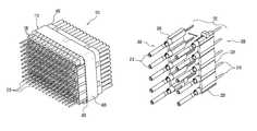
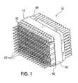
- FIG. 1is a perspective view of a connector according to an exemplary embodiment of the present invention, showing the connector populated with overmolded contact wafer assemblies;
- FIG. 2 ais a perspective view of a plurality of contacts of an exemplary embodiment of the present invention, showing a group of the contacts being overmolded to form a wafer;
- FIG. 2 bis a perspective view of a wafer resulting from the overmolding illustrated in FIG. 2 a;
- FIG. 2 cis a perspective view of the wafer illustrated in FIG. 2 b , showing the wafer with mating hoods;
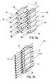
- FIG. 3 ais a perspective view of two of the wafers illustrated in FIG. 2 c , showing the wafers being interlocked;
- FIG. 3 bis a perspective view of a wafer assembly formed by the interlocking of the two wafers illustrated in FIG. 3 a;
- FIG. 4is a rear perspective view of the connector illustrated in FIG. 1 , showing one wafer assembly received in the connector;
- FIG. 5is an enlarged partial sectional view of the connector illustrated in FIG. 4 , through line 5 - 5 ;
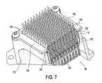
- FIG. 7is a perspective view an alternative embodiment of the connector illustrated in FIG. 1 , showing retention plates added to the connector.
- the connector 100generally includes a housing 110 that holds a plurality of wafer assemblies 120 having ends exposed on either side of the housing 110 .
- the housing 110is preferably a unitary one-piece member.
- the housing 110includes one side 400 that interfaces with the mating connector and another side 402 opposite thereof that faces the printed circuit board.
- a plurality of cavities 404extend between the sides 400 and 402 .
- the cavities 404are preferably arranged in a number of columns and rows. Each cavity 404 has an installation end 408 and a contact end 410 , as best seen in FIG. 5 .
- the installation ends 408 of the cavitiesdefine the face of the printed circuit board side 402 of the housing 110 and the contact ends 410 define the face of the interface side 400 of the housing 110 .
- An overhang 420may be provided around the perimeter of the printed circuit board side 402 such that the face thereof is recessed, as seen in FIG. 4 .
- the overhang 420covers a portion of the wafer assemblies 120 .
- Each wafer assembly 120is formed by interlocking two wafers 200 , as illustrated in FIGS. 3 a and 3 b .
- Each wafer 200includes a plurality of contacts 210 held together by an overmold 220 .
- Each contact 210includes a mating end 212 and an opposite tail end 214 .
- the ends 212 and 214 of each contact 210are exposed at either side of the overmold 220 .
- the mating ends 212 of the contacts 210may include flexible tabs ( FIG. 2 b ) that are adapted to engage a mating contact and the tail ends 214 are adapted to engage the printed circuit board, such as by soldering or press fit.
- the overmold 220is preferably a unitary one-piece member that includes opposite sides 222 and 224 and opposite ends 226 and 228 .
- the first side 222includes recessed surfaces 230 between the contacts, specifically between adjacent body portions 216 of the contacts. Each recessed surface 230 is designed to receive a corresponding portion of another overmold of another contact wafer, as seen in FIG. 3 a .
- the opposite second side 224 ( FIG. 3 a ) of the overmold 220is substantially flat.
- the overmold 220may include a stopping tab 232 extending from one of its ends 226 or 228 in a direction substantially perpendicular to the recessed surfaces 230 , as seen in FIG. 2 c .
- the stopping tab 232is adapted to stop against the housing 110 when installing the wafer assemblies 120 therein.
- the overmold 220may also include a stopping shoulder 234 near the mating end 212 of each contact that engages the installation ends 408 of the housing cavities 404 , as best seen in FIG. 5 .
- each wafer assembly 120has a row of 10 contacts with a pitch of 0.100 inches between contacts.
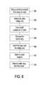
- FIG. 6illustrates the method of manufacturing the connector 100 .
- the methodincludes forming first and second contact wafers by first forming the contacts 210 by stamping a metal sheet at step 800 .
- the mating ends 212 of the contacts 210may optionally be selectively plated, such as by gold plating, at step 802 .
- the overmold 220is applied to a group of the contacts 210 for each contact wafer at step 804 . In a preferred embodiment, the overmold 220 is applied to five contacts at a 0.200 inch pitch.
- the carrier strip 211is then removed from the contacts 210 of each wafer at step 806 and the mating hoods 215 are installed on the mating ends 212 of the contacts 210 at step 808 .
- the wafersare then interlocked with one another at step 810 such that the recessed surfaces 230 of each wafer accepts a corresponding portion of the other wafer, thereby forming the wafer assembly 120 .
- the waferspreferably fit together in a slight press-fit.
- the wafer assembly 120can then be installed into the housing 110 from the printed circuit board side 402 of the housing at step 812 .
- the wafer assembly 120is installed such that each contact 210 is received in a respective cavity 404 until the stopping shoulders 234 of the overmold 220 abuts the installation end 408 of each cavity 404 , as seen in FIG. 5 .
- the stopping tab 232 of the overmold 220also abuts the overhang 420 of the housing 110 to prevent the wafer assembly 120 from being inserted too far into the housing 110 .
- the contact mating ends 212are exposed at one side and ready to engage a mating component and the contact tail ends 214 are exposed at the other side and ready to engage a printed circuit board.
- a plurality of wafer assemblies 120can be similarly installed in the housing 110 to form the connector 110 , as seen in FIG. 1 .
- FIG. 7illustrates an alternative embodiment of the present invention that includes one or more retention plates 700 and 702 provided at the printed circuit board side 402 of the housing 110 to secure the wafer assemblies 120 in the housing 110 .
- the retention plates 700 and 702are configured to cover the stopping tabs 232 of the wafer assemblies to prevent the wafer assemblies 120 from backing out of the housing 110 .
- the retention plates 700 and 702are preferably attached to a support 710 of the connector 100 by any known manner, such as screw fasteners 712 .
- the overmold 220 of the wafers 200 of each of the wafer assemblies 120may optionally include an inwardly extending locking tab 720 that engages a corresponding channel 722 of the adjacent interlocked wafer that forms the wafer assembly.
- the locking tab 720 and channel 722provide an additional mechanism for securing the two wafers 200 together that form the water assembly.
Landscapes
- Engineering & Computer Science (AREA)
- Manufacturing & Machinery (AREA)
- Coupling Device And Connection With Printed Circuit (AREA)
- Details Of Connecting Devices For Male And Female Coupling (AREA)
- Connector Housings Or Holding Contact Members (AREA)
- Manufacturing Of Electrical Connectors (AREA)
Abstract
Description
The present invention relates to an overmolded contact wafer and an electrical connector including the same.
Electrical connectors used in the aeronautics industry are required to meet the standards set by Airlines Electronic Engineering Committee, such as ARINC 600. Conventional ARINC connectors typically have a body with two parts including a front insert and a rear insert with corresponding passageways in each for receiving contacts. Multiple steps are required to assemble the conventional ARINC connector including machining individual contacts, installing retaining clips in the passageways of the front insert, bonding the front and rear inserts, and finally installing the contacts into the passageways such that the retaining clips retain the contacts in the passageways. Thus, the conventional ARINC connectors require a number of parts that must be individually assembled together. The conventional ARINC connectors are also bulky and heavy.
Therefore, a need exists for a simplified connector that can be easily made and assembled, is lighter in weight, and meets the ARINC standard.
Accordingly, the present invention provides a contact wafer that has a plurality of contacts. Each of the contacts has a body portion with a mating end and an opposite tail end. The mating end is configured to couple to a mating contact and the tail end is configured to engage a printed circuit board. An overmold surrounds the body portions of the contacts such that the mating ends and the tails ends of the contacts are exposed and extend from opposite ends of said overmold. The overmold has a first side that includes a plurality of recessed surfaces. Each recessed surface is between adjacent body portions of the contacts and sized to receive a corresponding portion of an overmold of another contact wafer.
The present invention also provides a connector that includes a housing that has a mating interface side and a printed circuit board engagement side opposite the mating interface side, and at least one cavity extending between the mating interface and printed circuit board engagement sides. At least one contact is received in the at least one cavity. The contact includes a body portion with a mating end for coupling to a mating contact and a tail end opposite the mating end for engaging a printed circuit board. An overmold covers the body portion of the contact such that the mating and tail ends extend from opposite sides of the overmold and the mating end is exposed at the mating interface side of the housing and the tail end is exposed at the printed circuit board engagement side of the housing.
The present invention may also provide a connector that includes a housing that has a mating interface side and a printed circuit board engagement side opposite the mating interface side. A plurality of cavities extend between the mating interface and printed circuit board engagement sides. A wafer assembly is coupled to the housing. The wafer assembly includes first and second contact wafers. Each of the first and second contact wafers includes a plurality of contacts adapted to be received in the cavities of the housing. Each of the contacts has a body portion with a mating end and an opposite tail end. The mating end is configured to couple to a mating contact and the tail end is configured to engage a printed circuit board. An overmold surrounds the body portions of the plurality of contacts such that the mating ends and the tails ends of the contacts extend from opposite ends of the overmold and the mating ends are exposed at the mating interface side of the housing and the tail ends are exposed at the printed circuit board engagement side of the housing. The first and second contact wafers are interlocked with one another such that the contacts of the first contact wafer alternate with the contacts of the second contact wafer.
The present invention may further provide a method of manufacturing of a connector that includes the steps of forming a first contact wafer by providing a first group of contacts, each contact including a body portion, a mating end, and a tail end, and applying an overmold to the body portions; forming a second contact water by providing a second group of contacts, each contact including a body portion, a mating end, and a tail end, and applying an overmold to the body portions of the of contacts; interlocking the first and second contacts to form a wafer assembly such that the mating ends of the first and second contact wafers are aligned and the tail ends of the first and second contact wafers align; and installing the wafer assembly into a printed circuit board engagement side of a connector housing such that the mating ends of the first and second contact wafers are exposed at a mating interface side of the connector housing.
With those and other objects, advantages, and features of the invention that may become hereinafter apparent, the nature of the invention may be more clearly understood by reference to the following detailed description of the invention, the appended claims, and the several drawings attached herein.
A more complete appreciation of the invention and many of the attendant advantages thereof will be readily obtained as the same becomes better understood by reference to the following detailed description when considered in connection with the accompanying drawings, wherein:
Referring toFIGS. 1, 2 a-2c,3a,3b, and4-7, the present invention relates to anelectrical connector 100 and awafer assembly 120 therefor. Theconnector 100 preferably meets the ARINC 600 standard that has fewer components and is lighter in weight than conventional ARINC connectors. In a preferred embodiment, theconnector 100 has a weight reduction from convention connectors that is about 20 to 25% of the total connector weight. Theconnector 100 preferably receives a plurality ofwafer assemblies 120 which provide the connector with a high density ofcontacts 210. Thecontacts 210 are adapted to couple with a mating connector at one end and a printed circuit board at the other end, thereby electrically connecting the mating connector to the circuit board.
As seen inFIGS. 1 and 4 , theconnector 100 generally includes ahousing 110 that holds a plurality ofwafer assemblies 120 having ends exposed on either side of thehousing 110. Thehousing 110 is preferably a unitary one-piece member. Thehousing 110 includes oneside 400 that interfaces with the mating connector and anotherside 402 opposite thereof that faces the printed circuit board. A plurality ofcavities 404 extend between thesides cavities 404 are preferably arranged in a number of columns and rows. Eachcavity 404 has aninstallation end 408 and acontact end 410, as best seen inFIG. 5 . The installation ends408 of the cavities define the face of the printedcircuit board side 402 of thehousing 110 and thecontact ends 410 define the face of theinterface side 400 of thehousing 110. Anoverhang 420 may be provided around the perimeter of the printedcircuit board side 402 such that the face thereof is recessed, as seen inFIG. 4 . Theoverhang 420 covers a portion of thewafer assemblies 120.
Eachwafer assembly 120 is formed by interlocking twowafers 200, as illustrated inFIGS. 3aand 3b . Eachwafer 200 includes a plurality ofcontacts 210 held together by anovermold 220. Eachcontact 210 includes amating end 212 and anopposite tail end 214. The ends212 and214 of eachcontact 210 are exposed at either side of theovermold 220. The mating ends212 of thecontacts 210 may include flexible tabs (FIG. 2b ) that are adapted to engage a mating contact and the tail ends214 are adapted to engage the printed circuit board, such as by soldering or press fit. To make thewafer 200, a group of thecontacts 210 are overmolded to create theovermold 220 over the contacts, as seen inFIG. 2a . Thecarrier strip 211 is then removed at theends 212 of thecontacts 210, as seen inFIG. 2b .Mating hoods 215 can then be added to the mating ends212 of thecontacts 210, as seen inFIG. 2 c.
Theovermold 220 is preferably a unitary one-piece member that includesopposite sides first side 222 includes recessedsurfaces 230 between the contacts, specifically betweenadjacent body portions 216 of the contacts. Each recessedsurface 230 is designed to receive a corresponding portion of another overmold of another contact wafer, as seen inFIG. 3a . The opposite second side224 (FIG. 3a ) of theovermold 220 is substantially flat. Theovermold 220 may include a stoppingtab 232 extending from one of itsends surfaces 230, as seen inFIG. 2c . The stoppingtab 232 is adapted to stop against thehousing 110 when installing thewafer assemblies 120 therein. Theovermold 220 may also include a stoppingshoulder 234 near themating end 212 of each contact that engages the installation ends408 of thehousing cavities 404, as best seen inFIG. 5 .
As seen inFIG. 3b , once the twowafers 200 are interlocked, thecontacts 210 of the twowafers 200 alternate and are in alignment. That is, the mating ends212 of the contacts of both wafers will be aligned and likewise the tail ends214 of the contacts of both wafers will be aligned. In a preferred embodiment, eachwafer assembly 120 has a row of 10 contacts with a pitch of 0.100 inches between contacts.
As seen inFIG. 7 , theovermold 220 of thewafers 200 of each of thewafer assemblies 120 may optionally include an inwardly extendinglocking tab 720 that engages acorresponding channel 722 of the adjacent interlocked wafer that forms the wafer assembly. Thelocking tab 720 andchannel 722 provide an additional mechanism for securing the twowafers 200 together that form the water assembly.
Although certain presently preferred embodiments of the disclosed invention have been specifically described herein, it will be apparent to those skilled in the art to which the invention pertains that variations and modifications of the various embodiments shown and described herein may be made without departing from the spirit and scope of the invention. Accordingly, it is intended that the invention be limited only to the extent required by the appended claims and the applicable rules of law.
Claims (26)
1. A contact wafer, comprising:
a plurality of contacts, each of said contacts having a body portion with a mating end and an opposite tail end, said mating end being configured to couple to a mating contact and said tail end being configured to engage a printed circuit board; and
an overmold surrounding said body portions of said plurality of contacts such that said mating ends and said tails ends of said contacts are exposed and extend from opposite first and second ends of said overmold, said overmold having a first side including a plurality of recessed surfaces, each recessed surface being between adjacent body portions of said plurality of contacts and sized to receive a corresponding portion of an overmold of another contact wafer, and said overmold having a stopping member extending from a third end that extends between said first and second ends, said stopping member extending in a direction substantially perpendicular to a length of said plurality of recessed surfaces.
2. A contact wafer according toclaim 1 , wherein
said overmold is a unitary one-piece member.
3. A contact wafer according toclaim 1 , wherein
said overmold has a second side opposite said first side, said second side is substantially flat.
4. A contact wafer according toclaim 1 , wherein
said overmold includes an inwardly extending locking tab.
5. A contact wafer according toclaim 1 , wherein
said tail end is a solder or press fit end.
6. A contact wafer according toclaim 1 , wherein
each of said mating ends includes a mating hood.
7. A connector, comprising:
a housing having a mating interface side and a printed circuit board engagement side opposite said mating interface side, and at least one cavity extending between said mating interface and printed circuit board engagement sides;
at least one contact received in said at least one cavity, said contact including a body portion with a mating end for coupling to a mating contact and a tail end opposite said mating end for engaging a printed circuit board; and
an overmold covering said body portion of said contact such that said mating and tail ends extend from opposite first and second sides of said overmold and said mating end is exposed at said mating interface side of said housing and said tail end is exposed at said printed circuit board engagement side of said housing, and said overmold having a stopping member adapted to abut said housing, said stopping member extending from a third end of said overmold that extends between said first and second ends, said stopping member extending in a direction substantially perpendicular to a length of said plurality of recessed surfaces.
8. A connector according toclaim 7 , wherein
said housing includes an overhang extending substantially along a perimeter of said housing at said printed circuit board engagement side.
9. A connector according toclaim 7 , wherein
said housing is a unitary one-piece member.
10. A connector according toclaim 7 , wherein
said tail end is a solder or press fit end.
11. A connector, comprising:
a housing having a mating interface side and a printed circuit board engagement side opposite said mating interface side, a plurality of cavities extending between said mating interface and printed circuit board engagement sides; and
a wafer assembly coupled to said housing, said wafer assembly including first and second contact wafers, each of said first and second contact wafers including,
a plurality of contacts adapted to be received in said cavities of said housing, each of said contacts having a body portion with a mating end and an opposite tail end, said mating end being configured to couple to a mating contact and said tail end being configured to engage a printed circuit board, and
an overmold surrounding said body portions of said plurality of contacts such that said mating ends and said tails ends of said contacts extend from opposite ends of said overmold and said mating ends are exposed at said mating interface side of said housing and said tail ends are exposed at said printed circuit board engagement side of said housing,
wherein said first and second contact wafers are interlocked with one another such that said contacts of said first contact wafer alternate with said contacts of said second contact wafer, and
wherein said mating ends of said first and second contact wafers are aligned, and said tail ends of said first and second contact wafers are aligned.
12. A connector according toclaim 11 , wherein
each of said first and second contact wafers includes a first side that has a plurality of recessed surfaces between adjacent body portions of said plurality of contacts that are sized to receive a corresponding portion of an overmold of another contact wafer.
13. A connector according toclaim 11 , wherein
said overmold is a unitary one-piece member.
14. A connector according toclaim 11 , wherein
said first and second contact wafers are identical.
15. A connector according toclaim 11 , wherein
said housing includes an overhang extending substantially along a perimeter of said housing at said printed circuit board engagement side.
16. A connector according toclaim 11 , wherein
said overmold has opposite ends, and said overmold includes a stopping member that extends from one of said ends.
17. A connector according toclaim 11 , wherein
said cavities are arranged in rows and columns.
18. A connector according toclaim 11 , wherein
said housing includes at least one retention plate at said printed circuit board engagement side, said at least one retention plate covering a portion of said overmold of each of said first and second contact wafers.
19. A connector according toclaim 11 , wherein
said housing is a unitary one-piece member.
20. A method of manufacturing of a connector, comprising the steps of:
forming a first contact wafer by providing a first group of contacts, each contact including a body portion, a mating end, and a tail end, and applying an overmold to the body portions;
forming a second contact wafer by providing a second group of contacts, each contact including a body portion, a mating end, and a tail end, and applying an overmold to the body portions of the of contacts;
interlocking the first and second contacts to form a wafer assembly such that the mating ends of the first and second contact wafers are aligned and the tail ends of the first and second contact wafers align; and
installing the wafer assembly into a printed circuit board engagement side of a connector housing such that the mating ends of the first and second contact wafers are exposed at a mating interface side of the connector housing.
21. A method according toclaim 20 , further comprising the step of stamping the contacts of the first and second group of contacts.
22. A method according toclaim 21 , further comprising the step of removing a carrier strip after applying the overmold to the body portions of the contacts.
23. A method according toclaim 22 , further comprising the step of applying a mating hood to each of the mating ends of each of the contacts.
24. A method according toclaim 23 , further comprising the step of securing at least one retention plate to the printed circuit board engagement side of the connector housing.
25. A method according toclaim 23 , further comprising the step of installing a plurality of wafer assemblies into the printed circuit board engagement side of the connector housing.
26. A connector, comprising:
a housing having a mating interface side and a printed circuit board engagement side opposite said mating interface side, a plurality of cavities extending between said mating interface and printed circuit board engagement sides; and
a wafer assembly coupled to said housing, said wafer assembly including first and second contact wafers, each of said first and second contact wafers including,
a plurality of contacts adapted to be received in said cavities of said housing, each of said contacts having a body portion with a mating end and an opposite tail end, said mating end being configured to couple to a mating contact and said tail end being configured to engage a printed circuit board, and
an overmold surrounding said body portions of said plurality of contacts such that said mating ends and said tails ends of said contacts extend from opposite ends of said overmold and said mating ends are exposed at said mating interface side of said housing and said tail ends are exposed at said printed circuit board engagement side of said housing,
wherein said first and second contact wafers are interlocked with one another such that said contacts of said first contact wafer alternate with said contacts of said second contact wafer,
wherein said housing includes at least one retention plate at said printed circuit board engagement side, and said at least one retention plate covering a portion of said overmold of each of said first and second contact wafers.
Priority Applications (13)
| Application Number | Priority Date | Filing Date | Title |
|---|---|---|---|
| US14/475,983US9362638B2 (en) | 2014-09-03 | 2014-09-03 | Overmolded contact wafer and connector |
| AU2015312015AAU2015312015B2 (en) | 2014-09-03 | 2015-09-02 | Overmolded contact wafer and connector |
| KR1020177009039AKR20170070028A (en) | 2014-09-03 | 2015-09-02 | Overmolded contact wafer and connector |
| CA2960197ACA2960197C (en) | 2014-09-03 | 2015-09-02 | Overmolded contact wafer and connector |
| CN201580052570.8ACN106716726B (en) | 2014-09-03 | 2015-09-02 | Overmolded contact wafer and connector |
| PCT/US2015/048099WO2016036829A1 (en) | 2014-09-03 | 2015-09-02 | Overmolded contact wafer and connector |
| MX2017002908AMX395216B (en) | 2014-09-03 | 2015-09-02 | OVERMOLDED CONTACT WAFER AND CONNECTOR |
| BR112017004335ABR112017004335A2 (en) | 2014-09-03 | 2015-09-02 | overmolded contact wafer and connector. |
| MYPI2017700762AMY182184A (en) | 2014-09-03 | 2015-09-02 | Overmolded contact wafer and connector |
| JP2017512814AJP6542361B2 (en) | 2014-09-03 | 2015-09-02 | Overmolded contact wafer and connector |
| RU2017110893ARU2702338C2 (en) | 2014-09-03 | 2015-09-02 | Plate with pressure-tested contacts and connector |
| EP15838701.9AEP3189562B1 (en) | 2014-09-03 | 2015-09-02 | Overmolded contact wafer and connector |
| IL250932AIL250932B (en) | 2014-09-03 | 2017-03-05 | Overmolded contact wafer and connector |
Applications Claiming Priority (1)
| Application Number | Priority Date | Filing Date | Title |
|---|---|---|---|
| US14/475,983US9362638B2 (en) | 2014-09-03 | 2014-09-03 | Overmolded contact wafer and connector |
Publications (2)
| Publication Number | Publication Date |
|---|---|
| US20160064842A1 US20160064842A1 (en) | 2016-03-03 |
| US9362638B2true US9362638B2 (en) | 2016-06-07 |
Family
ID=55403594
Family Applications (1)
| Application Number | Title | Priority Date | Filing Date |
|---|---|---|---|
| US14/475,983ActiveUS9362638B2 (en) | 2014-09-03 | 2014-09-03 | Overmolded contact wafer and connector |
Country Status (13)
| Country | Link |
|---|---|
| US (1) | US9362638B2 (en) |
| EP (1) | EP3189562B1 (en) |
| JP (1) | JP6542361B2 (en) |
| KR (1) | KR20170070028A (en) |
| CN (1) | CN106716726B (en) |
| AU (1) | AU2015312015B2 (en) |
| BR (1) | BR112017004335A2 (en) |
| CA (1) | CA2960197C (en) |
| IL (1) | IL250932B (en) |
| MX (1) | MX395216B (en) |
| MY (1) | MY182184A (en) |
| RU (1) | RU2702338C2 (en) |
| WO (1) | WO2016036829A1 (en) |
Cited By (10)
| Publication number | Priority date | Publication date | Assignee | Title |
|---|---|---|---|---|
| US20170194744A1 (en)* | 2015-07-31 | 2017-07-06 | Samtec, Inc. | Configurable, high-bandwidth connector |
| US9991642B1 (en) | 2017-08-22 | 2018-06-05 | Amphenol Corporation | Filter wafer assembly for electrical connector |
| US20190067888A1 (en)* | 2017-08-22 | 2019-02-28 | Amphenol Corporation | Wafer assembly for electrical connector |
| US10498061B1 (en) | 2018-12-17 | 2019-12-03 | Te Connectivity Corporation | Coaxial connector assembly |
| US10505323B2 (en)* | 2018-01-19 | 2019-12-10 | Te Connectivity Corporation | Communication system having coaxial connector assembly |
| US10505322B2 (en) | 2018-01-19 | 2019-12-10 | Te Connectivity Corporation | Communication system having coaxial connector assembly |
| US10558000B2 (en) | 2018-01-22 | 2020-02-11 | Te Connectivity Corporation | Communication system having coaxial connector module and fiber optic module |
| US20200067236A1 (en)* | 2018-08-22 | 2020-02-27 | Amphenol Corporation | Assembly method for a printed circuit board electrical connector |
| US11025006B2 (en) | 2019-09-04 | 2021-06-01 | Te Connectivity Corporation | Communication system having connector assembly |
| US11088480B2 (en)* | 2017-06-13 | 2021-08-10 | Molex, Llc | High density receptacle |
Families Citing this family (1)
| Publication number | Priority date | Publication date | Assignee | Title |
|---|---|---|---|---|
| RU203309U1 (en)* | 2020-11-24 | 2021-03-31 | Федеральное государственное бюджетное образовательное учреждение высшего образования "Сибирский государственный индустриальный университет", ФГБОУ ВО "СибГИУ" | ELECTRIC CONTACT |
Citations (92)
| Publication number | Priority date | Publication date | Assignee | Title |
|---|---|---|---|---|
| US3548367A (en)* | 1969-05-27 | 1970-12-15 | Amp Inc | Wire splicing unit |
| US3605068A (en)* | 1964-12-17 | 1971-09-14 | Western Electric Co | Electric coupler |
| US3854790A (en)* | 1973-09-17 | 1974-12-17 | Bunker Ramo | Electrical connector assembly |
| US4033658A (en)* | 1976-02-27 | 1977-07-05 | Amp Incorporated | Connector assembly accepting different size post contacts therein |
| US4602831A (en)* | 1983-09-26 | 1986-07-29 | Amp Incorporated | Electrical connector and method of making same |
| US4641426A (en)* | 1985-06-21 | 1987-02-10 | Associated Enterprises, Inc. | Surface mount compatible connector system with mechanical integrity |
| US4655515A (en)* | 1985-07-12 | 1987-04-07 | Amp Incorporated | Double row electrical connector |
| US4865562A (en)* | 1988-02-01 | 1989-09-12 | Minnesota Mining And Manufacturing Company | Overmolded electrical contact for the manufacture of connectors |
| US4973264A (en)* | 1986-01-27 | 1990-11-27 | Amp Incorporated | Daisy chain connector |
| US5171161A (en)* | 1991-05-09 | 1992-12-15 | Molex Incorporated | Electrical connector assemblies |
| US5190472A (en)* | 1992-03-24 | 1993-03-02 | W. L. Gore & Associates, Inc. | Miniaturized high-density coaxial connector system with staggered grouper modules |
| US5194020A (en)* | 1991-06-17 | 1993-03-16 | W. L. Gore & Associates, Inc. | High-density coaxial interconnect system |
| US5288251A (en)* | 1991-12-25 | 1994-02-22 | Sumitomo Wiring Systems, Ltd. | Connector |
| US5320555A (en)* | 1992-02-06 | 1994-06-14 | Yazaki Corporation | Module type connector assembly |
| US5385490A (en)* | 1993-08-24 | 1995-01-31 | The Whitaker Corporation | Modular connector for use with multi-conductor cable |
| US5435757A (en)* | 1993-07-27 | 1995-07-25 | The Whitaker Corporation | Contact and alignment feature |
| US5499927A (en) | 1993-05-21 | 1996-03-19 | Texell Corp. | Zipper-type electrical connector |
| US5580283A (en)* | 1995-09-08 | 1996-12-03 | Molex Incorporated | Electrical connector having terminal modules |
| US5667411A (en)* | 1995-09-08 | 1997-09-16 | Molex Incorporated | Electrical connector having terminal alignment means |
| US5716237A (en)* | 1996-06-21 | 1998-02-10 | Lucent Technologies Inc. | Electrical connector with crosstalk compensation |
| US5722861A (en)* | 1996-02-28 | 1998-03-03 | Molex Incorporated | Electrical connector with terminals of varying lengths |
| US5775954A (en)* | 1995-06-02 | 1998-07-07 | Siemens Aktiengesellschaft | Electrical plug-in connector |
| US5816829A (en)* | 1997-08-13 | 1998-10-06 | Ulan Co., Ltd. | Electrical connector having arrays of terminals for a multi-conductor cable |
| US5957719A (en)* | 1996-09-18 | 1999-09-28 | Yazaki Corporation | Press-fitting connector assembling structure |
| US5967841A (en) | 1995-07-05 | 1999-10-19 | Auto Splice Systems, Inc. | Continuous molded plastic components or assemblies |
| US6007386A (en)* | 1996-09-03 | 1999-12-28 | Yazaki Corporation | Connector |
| US6042423A (en)* | 1997-02-27 | 2000-03-28 | The Whitaker Corporation | Alignment adapters for post header |
| US6093061A (en)* | 1998-07-31 | 2000-07-25 | The Whitaker Corporation | Electrical connector having terminal insert subassembly |
| US6106326A (en)* | 1998-05-27 | 2000-08-22 | Framatome Connectors Interlock, Inc. | Electrical connector with contact retaining module formed from reverse alternating modular frame pieces |
| US6176745B1 (en)* | 1998-04-08 | 2001-01-23 | Sumitomo Wiring Systems, Ltd. | Pressure contact connector |
| US6200171B1 (en) | 1999-11-30 | 2001-03-13 | Berg Technology, Inc. | Electrical connector with over-molded housing member and method of over-molding |
| US6231398B1 (en)* | 1998-04-15 | 2001-05-15 | Sumitomo Wiring Systems, Ltd. | Connector with upper and lower inner housing members |
| US6290548B1 (en)* | 1999-11-02 | 2001-09-18 | Jeff Yeh | Cable connector |
| US20020002016A1 (en)* | 2000-03-21 | 2002-01-03 | Kei Sato | Joint connector |
| US6343960B1 (en)* | 2000-07-17 | 2002-02-05 | Yazaki Corporation | Joint connector having housing bodies in stacks |
| US20020025731A1 (en)* | 2000-08-31 | 2002-02-28 | Yazaki Corporation | Terminal cover |
| US6354887B2 (en)* | 2000-01-31 | 2002-03-12 | Yazaki Corporation | Connector connecting structure |
| US6386925B1 (en)* | 1999-04-06 | 2002-05-14 | Yazaki Corporation | Press-contact joint connector |
| US20020123272A1 (en)* | 2001-02-16 | 2002-09-05 | Yazaki Corporation | Circuit forming element |
| US6461201B1 (en)* | 1999-03-31 | 2002-10-08 | Yazaki Corporation | Press-contact joint connector |
| US6592381B2 (en)* | 2001-01-25 | 2003-07-15 | Teradyne, Inc. | Waferized power connector |
| US20030236032A1 (en)* | 2002-05-29 | 2003-12-25 | Sumitomo Wiring Systems, Ltd. | Split-type connector |
| US6712626B2 (en)* | 1999-10-14 | 2004-03-30 | Berg Technology, Inc. | Electrical connector with continuous strip contacts |
| US20040077228A1 (en)* | 2002-10-22 | 2004-04-22 | Jerry Wu | Cable assembly |
| US6814620B1 (en)* | 2003-07-01 | 2004-11-09 | Hon Hai Precision Ind. Co. Ltd. | Electrical connector |
| US20040235321A1 (en)* | 2001-05-23 | 2004-11-25 | Akinori Mizumura | Board connecting connector and method for producing same |
| US6823587B2 (en)* | 2000-07-31 | 2004-11-30 | Tensolite Company | Method of making a cable structure for data signal transmission |
| US20040259420A1 (en)* | 2003-06-19 | 2004-12-23 | Jerry Wu | Cable assembly with improved grounding means |
| US20040266273A1 (en)* | 2003-06-25 | 2004-12-30 | Jerry Wu | Cable assembly with internal circuit modules |
| US6837748B2 (en) | 2002-11-13 | 2005-01-04 | Contour Electronics Limited | Connector |
| US6857899B2 (en)* | 1999-10-08 | 2005-02-22 | Tensolite Company | Cable structure with improved grounding termination in the connector |
| US6881100B2 (en)* | 2002-10-15 | 2005-04-19 | Texas Instruments Incorporation | Modular socket |
| US20050196987A1 (en)* | 2001-11-14 | 2005-09-08 | Shuey Joseph B. | High density, low noise, high speed mezzanine connector |
| US6955565B2 (en)* | 2002-12-30 | 2005-10-18 | Molex Incorporated | Cable connector with shielded termination area |
| US6981883B2 (en)* | 2001-11-14 | 2006-01-03 | Fci Americas Technology, Inc. | Impedance control in electrical connectors |
| US7104808B2 (en)* | 2005-01-20 | 2006-09-12 | Hon Hai Precision Ind. Co., Ltd. | Mating extender for electrically connecting with two electrical connectors |
| US7108567B1 (en)* | 2005-11-07 | 2006-09-19 | Hon Hai Precision Ind. Co., Ltd | Electrical device for interconnecting two printed circuit boards at a large distance |
| US7175479B1 (en)* | 2006-04-25 | 2007-02-13 | Tyco Electronics Corporation | Modular connector assembly with stamped retention latch members |
| US7229319B2 (en)* | 2005-06-24 | 2007-06-12 | Harting Electronics Gmbh & Co. Kg | Printed board connector for differential signal transmission |
| US20070141872A1 (en)* | 2005-12-15 | 2007-06-21 | Tyco Electronics Corporation | Electrical connector assembly having selective arrangement of signal and ground contacts |
| US7354318B2 (en)* | 2002-09-19 | 2008-04-08 | The Furukawa Electric Co., Ltd. | Joint connector |
| US7390200B2 (en)* | 2001-11-14 | 2008-06-24 | Fci Americas Technology, Inc. | High speed differential transmission structures without grounds |
| US7396259B2 (en)* | 2005-06-29 | 2008-07-08 | Fci Americas Technology, Inc. | Electrical connector housing alignment feature |
| US7407387B2 (en)* | 2001-07-31 | 2008-08-05 | Fci Americas Technology, Inc. | Modular mezzanine connector |
| US7422490B2 (en)* | 2004-06-25 | 2008-09-09 | Fci | Connector, connector assembling system and method of assembling a connector |
| US7431616B2 (en)* | 2006-03-03 | 2008-10-07 | Fci Americas Technology, Inc. | Orthogonal electrical connectors |
| US20090011645A1 (en)* | 2007-06-20 | 2009-01-08 | Molex Incorporated | Mezzanine-style connector with serpentine ground structure |
| US7572154B2 (en)* | 2007-08-10 | 2009-08-11 | Sumitomo Wiring Systems, Ltd. | Joint connector |
| US7572156B2 (en)* | 2007-10-17 | 2009-08-11 | Tyco Electronics Corporation | Apparatus for stabilizing and securing contact modules within an electrical connector assembly |
| US7713096B2 (en)* | 2008-01-07 | 2010-05-11 | Lear Corporation | Modular electrical connector |
| US7744416B2 (en)* | 2007-06-07 | 2010-06-29 | Hon Hai Precision Ind. Co., Ltd. | High speed electrical connector assembly with shieldding system |
| US7744380B2 (en) | 2007-02-21 | 2010-06-29 | Fci Americas Technology, Inc | Overmolded electrical contact array |
| US7837514B2 (en)* | 2008-10-01 | 2010-11-23 | Tyco Electronics Corporation | Electrical connectors with vertically oriented contacts |
| US20100311278A1 (en) | 2009-06-05 | 2010-12-09 | Tyco Electronics Corporation | Connector assembly having a unitary housing |
| US7862387B2 (en)* | 2006-01-06 | 2011-01-04 | Fci | Board connector module for mezzanine circuit board assemblies |
| US7927144B2 (en)* | 2009-08-10 | 2011-04-19 | 3M Innovative Properties Company | Electrical connector with interlocking plates |
| US7967638B1 (en)* | 2010-03-26 | 2011-06-28 | Hon Hai Precision Ind. Co., Ltd. | Mezzanine connector with contact wafers having opposite mounting tails |
| US7976345B2 (en)* | 2005-12-15 | 2011-07-12 | Tyco Electronics Corporation | Electrical contact assembly and method of manufacturing thereof |
| US7997933B2 (en)* | 2009-08-10 | 2011-08-16 | 3M Innovative Properties Company | Electrical connector system |
| US8038465B2 (en)* | 2008-01-07 | 2011-10-18 | Lear Corporation | Electrical connector and heat sink |
| US8147268B2 (en)* | 2007-08-30 | 2012-04-03 | Fci Americas Technology Llc | Mezzanine-type electrical connectors |
| US8147254B2 (en)* | 2007-11-15 | 2012-04-03 | Fci Americas Technology Llc | Electrical connector mating guide |
| US8210876B2 (en)* | 2006-05-23 | 2012-07-03 | Fci | Connector, connector assembling system and method of assembling a connector |
| US20120202386A1 (en)* | 2011-02-02 | 2012-08-09 | Amphenol Corporation | Mezzanine connector |
| US20120225576A1 (en)* | 2011-03-04 | 2012-09-06 | Sumitomo Wiring Systems, Ltd. | Connector |
| US20130122755A1 (en)* | 2011-11-14 | 2013-05-16 | Jason Smith | Electrical Connector with Wafer Having Inwardly Biasing Dovetail |
| US20130237068A1 (en)* | 2012-03-09 | 2013-09-12 | Sumitomo Wiring Systems, Ltd. | Electrical junction box |
| US8550855B2 (en)* | 2010-09-29 | 2013-10-08 | Tyco Electronics (Shanghai) Co. Ltd. | Electrical connector |
| US8662942B2 (en) | 2010-05-31 | 2014-03-04 | Zte Corporation | Universal serial bus head and manufacturing method thereof |
| US8684772B2 (en)* | 2011-12-27 | 2014-04-01 | Alltop Electronics (Suzhou) Ltd. | Electrical connector |
| US8784122B2 (en)* | 2011-11-14 | 2014-07-22 | Airborn, Inc. | Low-profile right-angle electrical connector assembly |
| US8915758B2 (en)* | 2011-12-28 | 2014-12-23 | Tyco Electronics Japan G.K. | Electrical connector |
Family Cites Families (11)
| Publication number | Priority date | Publication date | Assignee | Title |
|---|---|---|---|---|
| JPH0266865A (en)* | 1988-08-31 | 1990-03-06 | Nec Corp | Manufacture of connector |
| JPH0266865U (en)* | 1988-11-02 | 1990-05-21 | ||
| JPH0969378A (en)* | 1995-08-31 | 1997-03-11 | Japan Aviation Electron Ind Ltd | Connector terminal assembly, connector assembly using the same, and multi-core connector |
| DE19649549C1 (en)* | 1996-11-29 | 1998-04-09 | Bosch Gmbh Robert | Arrangement esp. for use in electronic controller of motor vehicle for connection to external pluggable connector |
| KR200205737Y1 (en)* | 2000-06-19 | 2000-12-01 | 이공범 | Connector Pinned Block Terminal |
| KR100774888B1 (en)* | 2001-09-06 | 2007-11-08 | 엘지이노텍 주식회사 | Pin structure of tuner |
| US6926562B1 (en)* | 2004-02-09 | 2005-08-09 | Hon Hai Precision Ind. Co., Ltd. | Cable end connector assembly with improved spacer |
| US7666014B2 (en)* | 2008-04-22 | 2010-02-23 | Hon Hai Precision Ind. Co., Ltd. | High density connector assembly having two-leveled contact interface |
| US7758357B2 (en)* | 2008-12-02 | 2010-07-20 | Hon Hai Precision Ind. Co., Ltd. | Receptacle backplane connector having interface mating with plug connectors having different pitch arrangement |
| US8079881B2 (en)* | 2009-06-05 | 2011-12-20 | Tyco Electronics Coporation | Connector shell having integrally formed connector inserts |
| US8716069B2 (en)* | 2012-09-28 | 2014-05-06 | Alpha & Omega Semiconductor, Inc. | Semiconductor device employing aluminum alloy lead-frame with anodized aluminum |
- 2014
- 2014-09-03USUS14/475,983patent/US9362638B2/enactiveActive
- 2015
- 2015-09-02WOPCT/US2015/048099patent/WO2016036829A1/enactiveApplication Filing
- 2015-09-02BRBR112017004335Apatent/BR112017004335A2/ennot_activeIP Right Cessation
- 2015-09-02CNCN201580052570.8Apatent/CN106716726B/enactiveActive
- 2015-09-02MYMYPI2017700762Apatent/MY182184A/enunknown
- 2015-09-02AUAU2015312015Apatent/AU2015312015B2/ennot_activeExpired - Fee Related
- 2015-09-02JPJP2017512814Apatent/JP6542361B2/enactiveActive
- 2015-09-02MXMX2017002908Apatent/MX395216B/enunknown
- 2015-09-02KRKR1020177009039Apatent/KR20170070028A/ennot_activeAbandoned
- 2015-09-02EPEP15838701.9Apatent/EP3189562B1/enactiveActive
- 2015-09-02CACA2960197Apatent/CA2960197C/enactiveActive
- 2015-09-02RURU2017110893Apatent/RU2702338C2/enactive
- 2017
- 2017-03-05ILIL250932Apatent/IL250932B/enactiveIP Right Grant
Patent Citations (108)
| Publication number | Priority date | Publication date | Assignee | Title |
|---|---|---|---|---|
| US3605068A (en)* | 1964-12-17 | 1971-09-14 | Western Electric Co | Electric coupler |
| US3548367A (en)* | 1969-05-27 | 1970-12-15 | Amp Inc | Wire splicing unit |
| US3854790A (en)* | 1973-09-17 | 1974-12-17 | Bunker Ramo | Electrical connector assembly |
| US4033658A (en)* | 1976-02-27 | 1977-07-05 | Amp Incorporated | Connector assembly accepting different size post contacts therein |
| US4602831A (en)* | 1983-09-26 | 1986-07-29 | Amp Incorporated | Electrical connector and method of making same |
| US4641426A (en)* | 1985-06-21 | 1987-02-10 | Associated Enterprises, Inc. | Surface mount compatible connector system with mechanical integrity |
| US4655515A (en)* | 1985-07-12 | 1987-04-07 | Amp Incorporated | Double row electrical connector |
| US4973264A (en)* | 1986-01-27 | 1990-11-27 | Amp Incorporated | Daisy chain connector |
| US4865562A (en)* | 1988-02-01 | 1989-09-12 | Minnesota Mining And Manufacturing Company | Overmolded electrical contact for the manufacture of connectors |
| US5171161A (en)* | 1991-05-09 | 1992-12-15 | Molex Incorporated | Electrical connector assemblies |
| US5194020A (en)* | 1991-06-17 | 1993-03-16 | W. L. Gore & Associates, Inc. | High-density coaxial interconnect system |
| US5288251A (en)* | 1991-12-25 | 1994-02-22 | Sumitomo Wiring Systems, Ltd. | Connector |
| US5320555A (en)* | 1992-02-06 | 1994-06-14 | Yazaki Corporation | Module type connector assembly |
| US5190472A (en)* | 1992-03-24 | 1993-03-02 | W. L. Gore & Associates, Inc. | Miniaturized high-density coaxial connector system with staggered grouper modules |
| US5499927A (en) | 1993-05-21 | 1996-03-19 | Texell Corp. | Zipper-type electrical connector |
| US5435757A (en)* | 1993-07-27 | 1995-07-25 | The Whitaker Corporation | Contact and alignment feature |
| US5385490A (en)* | 1993-08-24 | 1995-01-31 | The Whitaker Corporation | Modular connector for use with multi-conductor cable |
| US5775954A (en)* | 1995-06-02 | 1998-07-07 | Siemens Aktiengesellschaft | Electrical plug-in connector |
| US5967841A (en) | 1995-07-05 | 1999-10-19 | Auto Splice Systems, Inc. | Continuous molded plastic components or assemblies |
| US5667411A (en)* | 1995-09-08 | 1997-09-16 | Molex Incorporated | Electrical connector having terminal alignment means |
| US5580283A (en)* | 1995-09-08 | 1996-12-03 | Molex Incorporated | Electrical connector having terminal modules |
| US5722861A (en)* | 1996-02-28 | 1998-03-03 | Molex Incorporated | Electrical connector with terminals of varying lengths |
| US5716237A (en)* | 1996-06-21 | 1998-02-10 | Lucent Technologies Inc. | Electrical connector with crosstalk compensation |
| US6007386A (en)* | 1996-09-03 | 1999-12-28 | Yazaki Corporation | Connector |
| US5957719A (en)* | 1996-09-18 | 1999-09-28 | Yazaki Corporation | Press-fitting connector assembling structure |
| US6042423A (en)* | 1997-02-27 | 2000-03-28 | The Whitaker Corporation | Alignment adapters for post header |
| US5816829A (en)* | 1997-08-13 | 1998-10-06 | Ulan Co., Ltd. | Electrical connector having arrays of terminals for a multi-conductor cable |
| US6176745B1 (en)* | 1998-04-08 | 2001-01-23 | Sumitomo Wiring Systems, Ltd. | Pressure contact connector |
| US6231398B1 (en)* | 1998-04-15 | 2001-05-15 | Sumitomo Wiring Systems, Ltd. | Connector with upper and lower inner housing members |
| US6106326A (en)* | 1998-05-27 | 2000-08-22 | Framatome Connectors Interlock, Inc. | Electrical connector with contact retaining module formed from reverse alternating modular frame pieces |
| US6093061A (en)* | 1998-07-31 | 2000-07-25 | The Whitaker Corporation | Electrical connector having terminal insert subassembly |
| US6461201B1 (en)* | 1999-03-31 | 2002-10-08 | Yazaki Corporation | Press-contact joint connector |
| US6386925B1 (en)* | 1999-04-06 | 2002-05-14 | Yazaki Corporation | Press-contact joint connector |
| US6857899B2 (en)* | 1999-10-08 | 2005-02-22 | Tensolite Company | Cable structure with improved grounding termination in the connector |
| US6712626B2 (en)* | 1999-10-14 | 2004-03-30 | Berg Technology, Inc. | Electrical connector with continuous strip contacts |
| US6290548B1 (en)* | 1999-11-02 | 2001-09-18 | Jeff Yeh | Cable connector |
| US6200171B1 (en) | 1999-11-30 | 2001-03-13 | Berg Technology, Inc. | Electrical connector with over-molded housing member and method of over-molding |
| US6354887B2 (en)* | 2000-01-31 | 2002-03-12 | Yazaki Corporation | Connector connecting structure |
| US6406335B2 (en)* | 2000-03-21 | 2002-06-18 | Yazaki Corporation | Joint connector |
| US20020002016A1 (en)* | 2000-03-21 | 2002-01-03 | Kei Sato | Joint connector |
| US6343960B1 (en)* | 2000-07-17 | 2002-02-05 | Yazaki Corporation | Joint connector having housing bodies in stacks |
| US6823587B2 (en)* | 2000-07-31 | 2004-11-30 | Tensolite Company | Method of making a cable structure for data signal transmission |
| US20020025731A1 (en)* | 2000-08-31 | 2002-02-28 | Yazaki Corporation | Terminal cover |
| US6517389B2 (en)* | 2000-08-31 | 2003-02-11 | Yazaki Corporation | Terminal cover |
| US6592381B2 (en)* | 2001-01-25 | 2003-07-15 | Teradyne, Inc. | Waferized power connector |
| US20020123272A1 (en)* | 2001-02-16 | 2002-09-05 | Yazaki Corporation | Circuit forming element |
| US6592410B2 (en)* | 2001-02-16 | 2003-07-15 | Yazaki Corporation | Circuit forming element |
| US20040235321A1 (en)* | 2001-05-23 | 2004-11-25 | Akinori Mizumura | Board connecting connector and method for producing same |
| US7407387B2 (en)* | 2001-07-31 | 2008-08-05 | Fci Americas Technology, Inc. | Modular mezzanine connector |
| US20050196987A1 (en)* | 2001-11-14 | 2005-09-08 | Shuey Joseph B. | High density, low noise, high speed mezzanine connector |
| US7467955B2 (en)* | 2001-11-14 | 2008-12-23 | Fci Americas Technology, Inc. | Impedance control in electrical connectors |
| US7390200B2 (en)* | 2001-11-14 | 2008-06-24 | Fci Americas Technology, Inc. | High speed differential transmission structures without grounds |
| US6981883B2 (en)* | 2001-11-14 | 2006-01-03 | Fci Americas Technology, Inc. | Impedance control in electrical connectors |
| US20030236032A1 (en)* | 2002-05-29 | 2003-12-25 | Sumitomo Wiring Systems, Ltd. | Split-type connector |
| US7354318B2 (en)* | 2002-09-19 | 2008-04-08 | The Furukawa Electric Co., Ltd. | Joint connector |
| US7594830B2 (en)* | 2002-09-19 | 2009-09-29 | The Furukawa Electric Co., Ltd. | Joint connector |
| US7481682B2 (en)* | 2002-09-19 | 2009-01-27 | The Furukawa Electric Co., Ltd. | Joint connector |
| US6881100B2 (en)* | 2002-10-15 | 2005-04-19 | Texas Instruments Incorporation | Modular socket |
| US20040077228A1 (en)* | 2002-10-22 | 2004-04-22 | Jerry Wu | Cable assembly |
| US6837748B2 (en) | 2002-11-13 | 2005-01-04 | Contour Electronics Limited | Connector |
| US6955565B2 (en)* | 2002-12-30 | 2005-10-18 | Molex Incorporated | Cable connector with shielded termination area |
| US20040259420A1 (en)* | 2003-06-19 | 2004-12-23 | Jerry Wu | Cable assembly with improved grounding means |
| US20040266273A1 (en)* | 2003-06-25 | 2004-12-30 | Jerry Wu | Cable assembly with internal circuit modules |
| US6814620B1 (en)* | 2003-07-01 | 2004-11-09 | Hon Hai Precision Ind. Co. Ltd. | Electrical connector |
| US7422490B2 (en)* | 2004-06-25 | 2008-09-09 | Fci | Connector, connector assembling system and method of assembling a connector |
| US7104808B2 (en)* | 2005-01-20 | 2006-09-12 | Hon Hai Precision Ind. Co., Ltd. | Mating extender for electrically connecting with two electrical connectors |
| US7229319B2 (en)* | 2005-06-24 | 2007-06-12 | Harting Electronics Gmbh & Co. Kg | Printed board connector for differential signal transmission |
| US7396259B2 (en)* | 2005-06-29 | 2008-07-08 | Fci Americas Technology, Inc. | Electrical connector housing alignment feature |
| US7108567B1 (en)* | 2005-11-07 | 2006-09-19 | Hon Hai Precision Ind. Co., Ltd | Electrical device for interconnecting two printed circuit boards at a large distance |
| US20070141872A1 (en)* | 2005-12-15 | 2007-06-21 | Tyco Electronics Corporation | Electrical connector assembly having selective arrangement of signal and ground contacts |
| US7410392B2 (en)* | 2005-12-15 | 2008-08-12 | Tyco Electronics Corporation | Electrical connector assembly having selective arrangement of signal and ground contacts |
| US7976345B2 (en)* | 2005-12-15 | 2011-07-12 | Tyco Electronics Corporation | Electrical contact assembly and method of manufacturing thereof |
| US7862387B2 (en)* | 2006-01-06 | 2011-01-04 | Fci | Board connector module for mezzanine circuit board assemblies |
| US7431616B2 (en)* | 2006-03-03 | 2008-10-07 | Fci Americas Technology, Inc. | Orthogonal electrical connectors |
| US7175479B1 (en)* | 2006-04-25 | 2007-02-13 | Tyco Electronics Corporation | Modular connector assembly with stamped retention latch members |
| US8210876B2 (en)* | 2006-05-23 | 2012-07-03 | Fci | Connector, connector assembling system and method of assembling a connector |
| US7744380B2 (en) | 2007-02-21 | 2010-06-29 | Fci Americas Technology, Inc | Overmolded electrical contact array |
| US7744416B2 (en)* | 2007-06-07 | 2010-06-29 | Hon Hai Precision Ind. Co., Ltd. | High speed electrical connector assembly with shieldding system |
| US20090011645A1 (en)* | 2007-06-20 | 2009-01-08 | Molex Incorporated | Mezzanine-style connector with serpentine ground structure |
| US7572154B2 (en)* | 2007-08-10 | 2009-08-11 | Sumitomo Wiring Systems, Ltd. | Joint connector |
| US8147268B2 (en)* | 2007-08-30 | 2012-04-03 | Fci Americas Technology Llc | Mezzanine-type electrical connectors |
| US7572156B2 (en)* | 2007-10-17 | 2009-08-11 | Tyco Electronics Corporation | Apparatus for stabilizing and securing contact modules within an electrical connector assembly |
| US8147254B2 (en)* | 2007-11-15 | 2012-04-03 | Fci Americas Technology Llc | Electrical connector mating guide |
| US8038465B2 (en)* | 2008-01-07 | 2011-10-18 | Lear Corporation | Electrical connector and heat sink |
| US7713096B2 (en)* | 2008-01-07 | 2010-05-11 | Lear Corporation | Modular electrical connector |
| US7837514B2 (en)* | 2008-10-01 | 2010-11-23 | Tyco Electronics Corporation | Electrical connectors with vertically oriented contacts |
| US8083554B2 (en)* | 2009-06-05 | 2011-12-27 | Tyco Electronics Corporation | Connector assembly having a unitary housing |
| US20100311278A1 (en) | 2009-06-05 | 2010-12-09 | Tyco Electronics Corporation | Connector assembly having a unitary housing |
| US7927144B2 (en)* | 2009-08-10 | 2011-04-19 | 3M Innovative Properties Company | Electrical connector with interlocking plates |
| US7997933B2 (en)* | 2009-08-10 | 2011-08-16 | 3M Innovative Properties Company | Electrical connector system |
| US7967638B1 (en)* | 2010-03-26 | 2011-06-28 | Hon Hai Precision Ind. Co., Ltd. | Mezzanine connector with contact wafers having opposite mounting tails |
| US8662942B2 (en) | 2010-05-31 | 2014-03-04 | Zte Corporation | Universal serial bus head and manufacturing method thereof |
| US8550855B2 (en)* | 2010-09-29 | 2013-10-08 | Tyco Electronics (Shanghai) Co. Ltd. | Electrical connector |
| US20120202363A1 (en)* | 2011-02-02 | 2012-08-09 | Amphenol Corporation | Mezzanine connector |
| US8657627B2 (en)* | 2011-02-02 | 2014-02-25 | Amphenol Corporation | Mezzanine connector |
| US8801464B2 (en)* | 2011-02-02 | 2014-08-12 | Amphenol Corporation | Mezzanine connector |
| US8491313B2 (en)* | 2011-02-02 | 2013-07-23 | Amphenol Corporation | Mezzanine connector |
| US20120202386A1 (en)* | 2011-02-02 | 2012-08-09 | Amphenol Corporation | Mezzanine connector |
| US20120202387A1 (en)* | 2011-02-02 | 2012-08-09 | Amphenol Corporation | Mezzanine connector |
| US8636543B2 (en)* | 2011-02-02 | 2014-01-28 | Amphenol Corporation | Mezzanine connector |
| US8747168B2 (en)* | 2011-03-04 | 2014-06-10 | Sumitomo Wiring Systems, Ltd. | Stacking connector |
| US20120225576A1 (en)* | 2011-03-04 | 2012-09-06 | Sumitomo Wiring Systems, Ltd. | Connector |
| US8784122B2 (en)* | 2011-11-14 | 2014-07-22 | Airborn, Inc. | Low-profile right-angle electrical connector assembly |
| US20130122755A1 (en)* | 2011-11-14 | 2013-05-16 | Jason Smith | Electrical Connector with Wafer Having Inwardly Biasing Dovetail |
| US8684772B2 (en)* | 2011-12-27 | 2014-04-01 | Alltop Electronics (Suzhou) Ltd. | Electrical connector |
| US8915758B2 (en)* | 2011-12-28 | 2014-12-23 | Tyco Electronics Japan G.K. | Electrical connector |
| US20130237068A1 (en)* | 2012-03-09 | 2013-09-12 | Sumitomo Wiring Systems, Ltd. | Electrical junction box |
| US8936474B2 (en)* | 2012-03-09 | 2015-01-20 | Sumitomo Wiring Systems, Ltd. | Electrical junction box |
Cited By (18)
| Publication number | Priority date | Publication date | Assignee | Title |
|---|---|---|---|---|
| US20170194744A1 (en)* | 2015-07-31 | 2017-07-06 | Samtec, Inc. | Configurable, high-bandwidth connector |
| US9843135B2 (en)* | 2015-07-31 | 2017-12-12 | Samtec, Inc. | Configurable, high-bandwidth connector |
| US11088480B2 (en)* | 2017-06-13 | 2021-08-10 | Molex, Llc | High density receptacle |
| US9991642B1 (en) | 2017-08-22 | 2018-06-05 | Amphenol Corporation | Filter wafer assembly for electrical connector |
| US20190067888A1 (en)* | 2017-08-22 | 2019-02-28 | Amphenol Corporation | Wafer assembly for electrical connector |
| WO2019040410A1 (en) | 2017-08-22 | 2019-02-28 | Amphenol Corporation | Wafer assembly for electrical connector |
| US10243307B2 (en)* | 2017-08-22 | 2019-03-26 | Amphenol Corporation | Wafer assembly for electrical connector |
| US10505322B2 (en) | 2018-01-19 | 2019-12-10 | Te Connectivity Corporation | Communication system having coaxial connector assembly |
| US10505323B2 (en)* | 2018-01-19 | 2019-12-10 | Te Connectivity Corporation | Communication system having coaxial connector assembly |
| US10558000B2 (en) | 2018-01-22 | 2020-02-11 | Te Connectivity Corporation | Communication system having coaxial connector module and fiber optic module |
| US20200067236A1 (en)* | 2018-08-22 | 2020-02-27 | Amphenol Corporation | Assembly method for a printed circuit board electrical connector |
| EP3691045A1 (en) | 2018-08-22 | 2020-08-05 | Amphenol Corporation | Assembly method for a printed circuit board electrical connector |
| US10770839B2 (en)* | 2018-08-22 | 2020-09-08 | Amphenol Corporation | Assembly method for a printed circuit board electrical connector |
| US11223166B2 (en) | 2018-08-22 | 2022-01-11 | Amphenol Corporation | Printed circuit board electrical connector and assembly method for the same |
| EP4322343A2 (en) | 2018-08-22 | 2024-02-14 | Amphenol Corporation | Assembly method for a printed circuit board electrical connector |
| US10498061B1 (en) | 2018-12-17 | 2019-12-03 | Te Connectivity Corporation | Coaxial connector assembly |
| US11025006B2 (en) | 2019-09-04 | 2021-06-01 | Te Connectivity Corporation | Communication system having connector assembly |
| US12034251B2 (en) | 2019-09-04 | 2024-07-09 | Te Connectivity Solutions Gmbh | Communication system having connector assembly |
Also Published As
| Publication number | Publication date |
|---|---|
| AU2015312015A1 (en) | 2017-04-06 |
| JP2017527086A (en) | 2017-09-14 |
| IL250932A0 (en) | 2017-04-30 |
| EP3189562A1 (en) | 2017-07-12 |
| CN106716726B (en) | 2020-04-24 |
| MX2017002908A (en) | 2017-08-28 |
| EP3189562A4 (en) | 2018-05-16 |
| JP6542361B2 (en) | 2019-07-10 |
| RU2017110893A3 (en) | 2019-02-25 |
| RU2017110893A (en) | 2018-10-03 |
| MX395216B (en) | 2025-03-24 |
| MY182184A (en) | 2021-01-18 |
| EP3189562B1 (en) | 2021-10-20 |
| WO2016036829A1 (en) | 2016-03-10 |
| US20160064842A1 (en) | 2016-03-03 |
| BR112017004335A2 (en) | 2018-08-07 |
| CA2960197C (en) | 2023-10-03 |
| AU2015312015B2 (en) | 2021-03-04 |
| IL250932B (en) | 2021-04-29 |
| CA2960197A1 (en) | 2016-03-10 |
| KR20170070028A (en) | 2017-06-21 |
| CN106716726A (en) | 2017-05-24 |
| RU2702338C2 (en) | 2019-10-08 |
Similar Documents
| Publication | Publication Date | Title |
|---|---|---|
| US9362638B2 (en) | Overmolded contact wafer and connector | |
| US8690607B2 (en) | Joint connector | |
| US9800004B1 (en) | Busbar connector assembly | |
| US10243307B2 (en) | Wafer assembly for electrical connector | |
| KR20140096969A (en) | Connector | |
| US20140148058A1 (en) | Compliant pin connector mounting system and method | |
| EP3471216A1 (en) | Electrical connector | |
| US7841860B1 (en) | Compensating circuit board connector | |
| US9293857B2 (en) | Sealed and un-mated electrical connection system using single insertion press fit pins | |
| US7458148B2 (en) | Joint connector and method assembling the same | |
| US20100229379A1 (en) | Assembly aid for printed board connectors | |
| CN101950874B (en) | Connector plug part | |
| CN102570084B (en) | The electrical receptacle assembly of electrical connection adjacent circuit plate | |
| US9991642B1 (en) | Filter wafer assembly for electrical connector | |
| US20160336703A1 (en) | Splitter terminal and connector | |
| KR101029668B1 (en) | Surface Mount Header Assemblies | |
| KR101158489B1 (en) | Press-fit pin | |
| JP6076953B2 (en) | Board terminal | |
| KR101352637B1 (en) | Dust-cap having tester | |
| EP2696444B1 (en) | Joint connector | |
| US20140268611A1 (en) | System For Applying Power Directly Into Power Connectors For Modular Systems | |
| US7264504B2 (en) | Female multiple connector for electrical plug-type connectors | |
| JP2011155807A (en) | Circuit structure, electrical junction box, and manufacturing method of circuit structure |
Legal Events
| Date | Code | Title | Description |
|---|---|---|---|
| AS | Assignment | Owner name:AMPHENOL CORPORATION, CONNECTICUT Free format text:ASSIGNMENT OF ASSIGNORS INTEREST;ASSIGNORS:LJUBIJANKIC, ZLATAN;MARTEN, BARBARA H.;GIBSON, KAREN A.;AND OTHERS;REEL/FRAME:033716/0421 Effective date:20140905 | |
| STCF | Information on status: patent grant | Free format text:PATENTED CASE | |
| MAFP | Maintenance fee payment | Free format text:PAYMENT OF MAINTENANCE FEE, 4TH YEAR, LARGE ENTITY (ORIGINAL EVENT CODE: M1551); ENTITY STATUS OF PATENT OWNER: LARGE ENTITY Year of fee payment:4 | |
| MAFP | Maintenance fee payment | Free format text:PAYMENT OF MAINTENANCE FEE, 8TH YEAR, LARGE ENTITY (ORIGINAL EVENT CODE: M1552); ENTITY STATUS OF PATENT OWNER: LARGE ENTITY Year of fee payment:8 |