US9362141B2 - Microelectronic devices, stacked microelectronic devices, and methods for manufacturing such devices - Google Patents
Microelectronic devices, stacked microelectronic devices, and methods for manufacturing such devicesDownload PDFInfo
- Publication number
- US9362141B2 US9362141B2US13/898,004US201313898004AUS9362141B2US 9362141 B2US9362141 B2US 9362141B2US 201313898004 AUS201313898004 AUS 201313898004AUS 9362141 B2US9362141 B2US 9362141B2
- Authority
- US
- United States
- Prior art keywords
- support member
- casing
- interposer
- contacts
- interconnects
- Prior art date
- Legal status (The legal status is an assumption and is not a legal conclusion. Google has not performed a legal analysis and makes no representation as to the accuracy of the status listed.)
- Active
Links
Images


Classifications
- H—ELECTRICITY
- H01—ELECTRIC ELEMENTS
- H01L—SEMICONDUCTOR DEVICES NOT COVERED BY CLASS H10
- H01L23/00—Details of semiconductor or other solid state devices
- H01L23/02—Containers; Seals
- H01L23/04—Containers; Seals characterised by the shape of the container or parts, e.g. caps, walls
- H01L23/053—Containers; Seals characterised by the shape of the container or parts, e.g. caps, walls the container being a hollow construction and having an insulating or insulated base as a mounting for the semiconductor body
- H—ELECTRICITY
- H01—ELECTRIC ELEMENTS
- H01L—SEMICONDUCTOR DEVICES NOT COVERED BY CLASS H10
- H01L23/00—Details of semiconductor or other solid state devices
- H01L23/12—Mountings, e.g. non-detachable insulating substrates
- H—ELECTRICITY
- H01—ELECTRIC ELEMENTS
- H01L—SEMICONDUCTOR DEVICES NOT COVERED BY CLASS H10
- H01L21/00—Processes or apparatus adapted for the manufacture or treatment of semiconductor or solid state devices or of parts thereof
- H01L21/02—Manufacture or treatment of semiconductor devices or of parts thereof
- H01L21/04—Manufacture or treatment of semiconductor devices or of parts thereof the devices having potential barriers, e.g. a PN junction, depletion layer or carrier concentration layer
- H01L21/50—Assembly of semiconductor devices using processes or apparatus not provided for in a single one of the groups H01L21/18 - H01L21/326 or H10D48/04 - H10D48/07 e.g. sealing of a cap to a base of a container
- H01L21/56—Encapsulations, e.g. encapsulation layers, coatings
- H01L21/561—Batch processing
- H—ELECTRICITY
- H01—ELECTRIC ELEMENTS
- H01L—SEMICONDUCTOR DEVICES NOT COVERED BY CLASS H10
- H01L22/00—Testing or measuring during manufacture or treatment; Reliability measurements, i.e. testing of parts without further processing to modify the parts as such; Structural arrangements therefor
- H01L22/10—Measuring as part of the manufacturing process
- H—ELECTRICITY
- H01—ELECTRIC ELEMENTS
- H01L—SEMICONDUCTOR DEVICES NOT COVERED BY CLASS H10
- H01L23/00—Details of semiconductor or other solid state devices
- H01L23/28—Encapsulations, e.g. encapsulating layers, coatings, e.g. for protection
- H01L23/31—Encapsulations, e.g. encapsulating layers, coatings, e.g. for protection characterised by the arrangement or shape
- H01L23/3107—Encapsulations, e.g. encapsulating layers, coatings, e.g. for protection characterised by the arrangement or shape the device being completely enclosed
- H01L23/3121—Encapsulations, e.g. encapsulating layers, coatings, e.g. for protection characterised by the arrangement or shape the device being completely enclosed a substrate forming part of the encapsulation
- H01L23/3128—Encapsulations, e.g. encapsulating layers, coatings, e.g. for protection characterised by the arrangement or shape the device being completely enclosed a substrate forming part of the encapsulation the substrate having spherical bumps for external connection
- H—ELECTRICITY
- H01—ELECTRIC ELEMENTS
- H01L—SEMICONDUCTOR DEVICES NOT COVERED BY CLASS H10
- H01L23/00—Details of semiconductor or other solid state devices
- H01L23/28—Encapsulations, e.g. encapsulating layers, coatings, e.g. for protection
- H01L23/31—Encapsulations, e.g. encapsulating layers, coatings, e.g. for protection characterised by the arrangement or shape
- H01L23/3157—Partial encapsulation or coating
- H01L23/3178—Coating or filling in grooves made in the semiconductor body
- H—ELECTRICITY
- H01—ELECTRIC ELEMENTS
- H01L—SEMICONDUCTOR DEVICES NOT COVERED BY CLASS H10
- H01L23/00—Details of semiconductor or other solid state devices
- H01L23/48—Arrangements for conducting electric current to or from the solid state body in operation, e.g. leads, terminal arrangements ; Selection of materials therefor
- H01L23/488—Arrangements for conducting electric current to or from the solid state body in operation, e.g. leads, terminal arrangements ; Selection of materials therefor consisting of soldered or bonded constructions
- H01L23/498—Leads, i.e. metallisations or lead-frames on insulating substrates, e.g. chip carriers
- H01L23/49805—Leads, i.e. metallisations or lead-frames on insulating substrates, e.g. chip carriers the leads being also applied on the sidewalls or the bottom of the substrate, e.g. leadless packages for surface mounting
- H—ELECTRICITY
- H01—ELECTRIC ELEMENTS
- H01L—SEMICONDUCTOR DEVICES NOT COVERED BY CLASS H10
- H01L23/00—Details of semiconductor or other solid state devices
- H01L23/48—Arrangements for conducting electric current to or from the solid state body in operation, e.g. leads, terminal arrangements ; Selection of materials therefor
- H01L23/488—Arrangements for conducting electric current to or from the solid state body in operation, e.g. leads, terminal arrangements ; Selection of materials therefor consisting of soldered or bonded constructions
- H01L23/498—Leads, i.e. metallisations or lead-frames on insulating substrates, e.g. chip carriers
- H01L23/49861—Lead-frames fixed on or encapsulated in insulating substrates
- H—ELECTRICITY
- H01—ELECTRIC ELEMENTS
- H01L—SEMICONDUCTOR DEVICES NOT COVERED BY CLASS H10
- H01L23/00—Details of semiconductor or other solid state devices
- H01L23/52—Arrangements for conducting electric current within the device in operation from one component to another, i.e. interconnections, e.g. wires, lead frames
- H01L23/538—Arrangements for conducting electric current within the device in operation from one component to another, i.e. interconnections, e.g. wires, lead frames the interconnection structure between a plurality of semiconductor chips being formed on, or in, insulating substrates
- H01L23/5389—Arrangements for conducting electric current within the device in operation from one component to another, i.e. interconnections, e.g. wires, lead frames the interconnection structure between a plurality of semiconductor chips being formed on, or in, insulating substrates the chips being integrally enclosed by the interconnect and support structures
- H—ELECTRICITY
- H01—ELECTRIC ELEMENTS
- H01L—SEMICONDUCTOR DEVICES NOT COVERED BY CLASS H10
- H01L24/00—Arrangements for connecting or disconnecting semiconductor or solid-state bodies; Methods or apparatus related thereto
- H01L24/01—Means for bonding being attached to, or being formed on, the surface to be connected, e.g. chip-to-package, die-attach, "first-level" interconnects; Manufacturing methods related thereto
- H01L24/10—Bump connectors ; Manufacturing methods related thereto
- H01L24/12—Structure, shape, material or disposition of the bump connectors prior to the connecting process
- H01L24/14—Structure, shape, material or disposition of the bump connectors prior to the connecting process of a plurality of bump connectors
- H—ELECTRICITY
- H01—ELECTRIC ELEMENTS
- H01L—SEMICONDUCTOR DEVICES NOT COVERED BY CLASS H10
- H01L24/00—Arrangements for connecting or disconnecting semiconductor or solid-state bodies; Methods or apparatus related thereto
- H01L24/01—Means for bonding being attached to, or being formed on, the surface to be connected, e.g. chip-to-package, die-attach, "first-level" interconnects; Manufacturing methods related thereto
- H01L24/10—Bump connectors ; Manufacturing methods related thereto
- H01L24/15—Structure, shape, material or disposition of the bump connectors after the connecting process
- H01L24/17—Structure, shape, material or disposition of the bump connectors after the connecting process of a plurality of bump connectors
- H—ELECTRICITY
- H01—ELECTRIC ELEMENTS
- H01L—SEMICONDUCTOR DEVICES NOT COVERED BY CLASS H10
- H01L24/00—Arrangements for connecting or disconnecting semiconductor or solid-state bodies; Methods or apparatus related thereto
- H01L24/01—Means for bonding being attached to, or being formed on, the surface to be connected, e.g. chip-to-package, die-attach, "first-level" interconnects; Manufacturing methods related thereto
- H01L24/42—Wire connectors; Manufacturing methods related thereto
- H01L24/44—Structure, shape, material or disposition of the wire connectors prior to the connecting process
- H01L24/46—Structure, shape, material or disposition of the wire connectors prior to the connecting process of a plurality of wire connectors
- H—ELECTRICITY
- H01—ELECTRIC ELEMENTS
- H01L—SEMICONDUCTOR DEVICES NOT COVERED BY CLASS H10
- H01L24/00—Arrangements for connecting or disconnecting semiconductor or solid-state bodies; Methods or apparatus related thereto
- H01L24/01—Means for bonding being attached to, or being formed on, the surface to be connected, e.g. chip-to-package, die-attach, "first-level" interconnects; Manufacturing methods related thereto
- H01L24/42—Wire connectors; Manufacturing methods related thereto
- H01L24/47—Structure, shape, material or disposition of the wire connectors after the connecting process
- H01L24/48—Structure, shape, material or disposition of the wire connectors after the connecting process of an individual wire connector
- H—ELECTRICITY
- H01—ELECTRIC ELEMENTS
- H01L—SEMICONDUCTOR DEVICES NOT COVERED BY CLASS H10
- H01L24/00—Arrangements for connecting or disconnecting semiconductor or solid-state bodies; Methods or apparatus related thereto
- H01L24/93—Batch processes
- H01L24/95—Batch processes at chip-level, i.e. with connecting carried out on a plurality of singulated devices, i.e. on diced chips
- H01L24/97—Batch processes at chip-level, i.e. with connecting carried out on a plurality of singulated devices, i.e. on diced chips the devices being connected to a common substrate, e.g. interposer, said common substrate being separable into individual assemblies after connecting
- H—ELECTRICITY
- H01—ELECTRIC ELEMENTS
- H01L—SEMICONDUCTOR DEVICES NOT COVERED BY CLASS H10
- H01L25/00—Assemblies consisting of a plurality of semiconductor or other solid state devices
- H01L25/03—Assemblies consisting of a plurality of semiconductor or other solid state devices all the devices being of a type provided for in a single subclass of subclasses H10B, H10D, H10F, H10H, H10K or H10N, e.g. assemblies of rectifier diodes
- H01L25/04—Assemblies consisting of a plurality of semiconductor or other solid state devices all the devices being of a type provided for in a single subclass of subclasses H10B, H10D, H10F, H10H, H10K or H10N, e.g. assemblies of rectifier diodes the devices not having separate containers
- H01L25/065—Assemblies consisting of a plurality of semiconductor or other solid state devices all the devices being of a type provided for in a single subclass of subclasses H10B, H10D, H10F, H10H, H10K or H10N, e.g. assemblies of rectifier diodes the devices not having separate containers the devices being of a type provided for in group H10D89/00
- H01L25/0657—Stacked arrangements of devices
- H—ELECTRICITY
- H01—ELECTRIC ELEMENTS
- H01L—SEMICONDUCTOR DEVICES NOT COVERED BY CLASS H10
- H01L25/00—Assemblies consisting of a plurality of semiconductor or other solid state devices
- H01L25/03—Assemblies consisting of a plurality of semiconductor or other solid state devices all the devices being of a type provided for in a single subclass of subclasses H10B, H10D, H10F, H10H, H10K or H10N, e.g. assemblies of rectifier diodes
- H01L25/04—Assemblies consisting of a plurality of semiconductor or other solid state devices all the devices being of a type provided for in a single subclass of subclasses H10B, H10D, H10F, H10H, H10K or H10N, e.g. assemblies of rectifier diodes the devices not having separate containers
- H01L25/07—Assemblies consisting of a plurality of semiconductor or other solid state devices all the devices being of a type provided for in a single subclass of subclasses H10B, H10D, H10F, H10H, H10K or H10N, e.g. assemblies of rectifier diodes the devices not having separate containers the devices being of a type provided for in group subclass H10D
- H01L25/074—Stacked arrangements of non-apertured devices
- H—ELECTRICITY
- H01—ELECTRIC ELEMENTS
- H01L—SEMICONDUCTOR DEVICES NOT COVERED BY CLASS H10
- H01L25/00—Assemblies consisting of a plurality of semiconductor or other solid state devices
- H01L25/03—Assemblies consisting of a plurality of semiconductor or other solid state devices all the devices being of a type provided for in a single subclass of subclasses H10B, H10D, H10F, H10H, H10K or H10N, e.g. assemblies of rectifier diodes
- H01L25/10—Assemblies consisting of a plurality of semiconductor or other solid state devices all the devices being of a type provided for in a single subclass of subclasses H10B, H10D, H10F, H10H, H10K or H10N, e.g. assemblies of rectifier diodes the devices having separate containers
- H01L25/105—Assemblies consisting of a plurality of semiconductor or other solid state devices all the devices being of a type provided for in a single subclass of subclasses H10B, H10D, H10F, H10H, H10K or H10N, e.g. assemblies of rectifier diodes the devices having separate containers the devices being integrated devices of class H10
- H—ELECTRICITY
- H01—ELECTRIC ELEMENTS
- H01L—SEMICONDUCTOR DEVICES NOT COVERED BY CLASS H10
- H01L25/00—Assemblies consisting of a plurality of semiconductor or other solid state devices
- H01L25/03—Assemblies consisting of a plurality of semiconductor or other solid state devices all the devices being of a type provided for in a single subclass of subclasses H10B, H10D, H10F, H10H, H10K or H10N, e.g. assemblies of rectifier diodes
- H01L25/10—Assemblies consisting of a plurality of semiconductor or other solid state devices all the devices being of a type provided for in a single subclass of subclasses H10B, H10D, H10F, H10H, H10K or H10N, e.g. assemblies of rectifier diodes the devices having separate containers
- H01L25/11—Assemblies consisting of a plurality of semiconductor or other solid state devices all the devices being of a type provided for in a single subclass of subclasses H10B, H10D, H10F, H10H, H10K or H10N, e.g. assemblies of rectifier diodes the devices having separate containers the devices being of a type provided for in subclass H10D
- H01L25/117—Stacked arrangements of devices
- H—ELECTRICITY
- H01—ELECTRIC ELEMENTS
- H01L—SEMICONDUCTOR DEVICES NOT COVERED BY CLASS H10
- H01L2224/00—Indexing scheme for arrangements for connecting or disconnecting semiconductor or solid-state bodies and methods related thereto as covered by H01L24/00
- H01L2224/01—Means for bonding being attached to, or being formed on, the surface to be connected, e.g. chip-to-package, die-attach, "first-level" interconnects; Manufacturing methods related thereto
- H01L2224/02—Bonding areas; Manufacturing methods related thereto
- H01L2224/04—Structure, shape, material or disposition of the bonding areas prior to the connecting process
- H01L2224/05—Structure, shape, material or disposition of the bonding areas prior to the connecting process of an individual bonding area
- H01L2224/0554—External layer
- H01L2224/0555—Shape
- H01L2224/05552—Shape in top view
- H01L2224/05554—Shape in top view being square
- H—ELECTRICITY
- H01—ELECTRIC ELEMENTS
- H01L—SEMICONDUCTOR DEVICES NOT COVERED BY CLASS H10
- H01L2224/00—Indexing scheme for arrangements for connecting or disconnecting semiconductor or solid-state bodies and methods related thereto as covered by H01L24/00
- H01L2224/01—Means for bonding being attached to, or being formed on, the surface to be connected, e.g. chip-to-package, die-attach, "first-level" interconnects; Manufacturing methods related thereto
- H01L2224/10—Bump connectors; Manufacturing methods related thereto
- H01L2224/15—Structure, shape, material or disposition of the bump connectors after the connecting process
- H01L2224/16—Structure, shape, material or disposition of the bump connectors after the connecting process of an individual bump connector
- H—ELECTRICITY
- H01—ELECTRIC ELEMENTS
- H01L—SEMICONDUCTOR DEVICES NOT COVERED BY CLASS H10
- H01L2224/00—Indexing scheme for arrangements for connecting or disconnecting semiconductor or solid-state bodies and methods related thereto as covered by H01L24/00
- H01L2224/01—Means for bonding being attached to, or being formed on, the surface to be connected, e.g. chip-to-package, die-attach, "first-level" interconnects; Manufacturing methods related thereto
- H01L2224/26—Layer connectors, e.g. plate connectors, solder or adhesive layers; Manufacturing methods related thereto
- H01L2224/31—Structure, shape, material or disposition of the layer connectors after the connecting process
- H01L2224/32—Structure, shape, material or disposition of the layer connectors after the connecting process of an individual layer connector
- H01L2224/321—Disposition
- H01L2224/32135—Disposition the layer connector connecting between different semiconductor or solid-state bodies, i.e. chip-to-chip
- H01L2224/32145—Disposition the layer connector connecting between different semiconductor or solid-state bodies, i.e. chip-to-chip the bodies being stacked
- H—ELECTRICITY
- H01—ELECTRIC ELEMENTS
- H01L—SEMICONDUCTOR DEVICES NOT COVERED BY CLASS H10
- H01L2224/00—Indexing scheme for arrangements for connecting or disconnecting semiconductor or solid-state bodies and methods related thereto as covered by H01L24/00
- H01L2224/01—Means for bonding being attached to, or being formed on, the surface to be connected, e.g. chip-to-package, die-attach, "first-level" interconnects; Manufacturing methods related thereto
- H01L2224/26—Layer connectors, e.g. plate connectors, solder or adhesive layers; Manufacturing methods related thereto
- H01L2224/31—Structure, shape, material or disposition of the layer connectors after the connecting process
- H01L2224/32—Structure, shape, material or disposition of the layer connectors after the connecting process of an individual layer connector
- H01L2224/321—Disposition
- H01L2224/32151—Disposition the layer connector connecting between a semiconductor or solid-state body and an item not being a semiconductor or solid-state body, e.g. chip-to-substrate, chip-to-passive
- H01L2224/32221—Disposition the layer connector connecting between a semiconductor or solid-state body and an item not being a semiconductor or solid-state body, e.g. chip-to-substrate, chip-to-passive the body and the item being stacked
- H01L2224/32225—Disposition the layer connector connecting between a semiconductor or solid-state body and an item not being a semiconductor or solid-state body, e.g. chip-to-substrate, chip-to-passive the body and the item being stacked the item being non-metallic, e.g. insulating substrate with or without metallisation
- H—ELECTRICITY
- H01—ELECTRIC ELEMENTS
- H01L—SEMICONDUCTOR DEVICES NOT COVERED BY CLASS H10
- H01L2224/00—Indexing scheme for arrangements for connecting or disconnecting semiconductor or solid-state bodies and methods related thereto as covered by H01L24/00
- H01L2224/01—Means for bonding being attached to, or being formed on, the surface to be connected, e.g. chip-to-package, die-attach, "first-level" interconnects; Manufacturing methods related thereto
- H01L2224/42—Wire connectors; Manufacturing methods related thereto
- H01L2224/44—Structure, shape, material or disposition of the wire connectors prior to the connecting process
- H01L2224/45—Structure, shape, material or disposition of the wire connectors prior to the connecting process of an individual wire connector
- H01L2224/45001—Core members of the connector
- H01L2224/45099—Material
- H01L2224/451—Material with a principal constituent of the material being a metal or a metalloid, e.g. boron (B), silicon (Si), germanium (Ge), arsenic (As), antimony (Sb), tellurium (Te) and polonium (Po), and alloys thereof
- H01L2224/45138—Material with a principal constituent of the material being a metal or a metalloid, e.g. boron (B), silicon (Si), germanium (Ge), arsenic (As), antimony (Sb), tellurium (Te) and polonium (Po), and alloys thereof the principal constituent melting at a temperature of greater than or equal to 950°C and less than 1550°C
- H01L2224/45144—Gold (Au) as principal constituent
- H—ELECTRICITY
- H01—ELECTRIC ELEMENTS
- H01L—SEMICONDUCTOR DEVICES NOT COVERED BY CLASS H10
- H01L2224/00—Indexing scheme for arrangements for connecting or disconnecting semiconductor or solid-state bodies and methods related thereto as covered by H01L24/00
- H01L2224/01—Means for bonding being attached to, or being formed on, the surface to be connected, e.g. chip-to-package, die-attach, "first-level" interconnects; Manufacturing methods related thereto
- H01L2224/42—Wire connectors; Manufacturing methods related thereto
- H01L2224/47—Structure, shape, material or disposition of the wire connectors after the connecting process
- H01L2224/48—Structure, shape, material or disposition of the wire connectors after the connecting process of an individual wire connector
- H01L2224/4801—Structure
- H01L2224/48011—Length
- H—ELECTRICITY
- H01—ELECTRIC ELEMENTS
- H01L—SEMICONDUCTOR DEVICES NOT COVERED BY CLASS H10
- H01L2224/00—Indexing scheme for arrangements for connecting or disconnecting semiconductor or solid-state bodies and methods related thereto as covered by H01L24/00
- H01L2224/01—Means for bonding being attached to, or being formed on, the surface to be connected, e.g. chip-to-package, die-attach, "first-level" interconnects; Manufacturing methods related thereto
- H01L2224/42—Wire connectors; Manufacturing methods related thereto
- H01L2224/47—Structure, shape, material or disposition of the wire connectors after the connecting process
- H01L2224/48—Structure, shape, material or disposition of the wire connectors after the connecting process of an individual wire connector
- H01L2224/4805—Shape
- H01L2224/4809—Loop shape
- H01L2224/48091—Arched
- H—ELECTRICITY
- H01—ELECTRIC ELEMENTS
- H01L—SEMICONDUCTOR DEVICES NOT COVERED BY CLASS H10
- H01L2224/00—Indexing scheme for arrangements for connecting or disconnecting semiconductor or solid-state bodies and methods related thereto as covered by H01L24/00
- H01L2224/01—Means for bonding being attached to, or being formed on, the surface to be connected, e.g. chip-to-package, die-attach, "first-level" interconnects; Manufacturing methods related thereto
- H01L2224/42—Wire connectors; Manufacturing methods related thereto
- H01L2224/47—Structure, shape, material or disposition of the wire connectors after the connecting process
- H01L2224/48—Structure, shape, material or disposition of the wire connectors after the connecting process of an individual wire connector
- H01L2224/481—Disposition
- H01L2224/48151—Connecting between a semiconductor or solid-state body and an item not being a semiconductor or solid-state body, e.g. chip-to-substrate, chip-to-passive
- H01L2224/48221—Connecting between a semiconductor or solid-state body and an item not being a semiconductor or solid-state body, e.g. chip-to-substrate, chip-to-passive the body and the item being stacked
- H01L2224/48225—Connecting between a semiconductor or solid-state body and an item not being a semiconductor or solid-state body, e.g. chip-to-substrate, chip-to-passive the body and the item being stacked the item being non-metallic, e.g. insulating substrate with or without metallisation
- H01L2224/48227—Connecting between a semiconductor or solid-state body and an item not being a semiconductor or solid-state body, e.g. chip-to-substrate, chip-to-passive the body and the item being stacked the item being non-metallic, e.g. insulating substrate with or without metallisation connecting the wire to a bond pad of the item
- H—ELECTRICITY
- H01—ELECTRIC ELEMENTS
- H01L—SEMICONDUCTOR DEVICES NOT COVERED BY CLASS H10
- H01L2224/00—Indexing scheme for arrangements for connecting or disconnecting semiconductor or solid-state bodies and methods related thereto as covered by H01L24/00
- H01L2224/01—Means for bonding being attached to, or being formed on, the surface to be connected, e.g. chip-to-package, die-attach, "first-level" interconnects; Manufacturing methods related thereto
- H01L2224/42—Wire connectors; Manufacturing methods related thereto
- H01L2224/47—Structure, shape, material or disposition of the wire connectors after the connecting process
- H01L2224/48—Structure, shape, material or disposition of the wire connectors after the connecting process of an individual wire connector
- H01L2224/481—Disposition
- H01L2224/48151—Connecting between a semiconductor or solid-state body and an item not being a semiconductor or solid-state body, e.g. chip-to-substrate, chip-to-passive
- H01L2224/48221—Connecting between a semiconductor or solid-state body and an item not being a semiconductor or solid-state body, e.g. chip-to-substrate, chip-to-passive the body and the item being stacked
- H01L2224/48225—Connecting between a semiconductor or solid-state body and an item not being a semiconductor or solid-state body, e.g. chip-to-substrate, chip-to-passive the body and the item being stacked the item being non-metallic, e.g. insulating substrate with or without metallisation
- H01L2224/4824—Connecting between the body and an opposite side of the item with respect to the body
- H—ELECTRICITY
- H01—ELECTRIC ELEMENTS
- H01L—SEMICONDUCTOR DEVICES NOT COVERED BY CLASS H10
- H01L2224/00—Indexing scheme for arrangements for connecting or disconnecting semiconductor or solid-state bodies and methods related thereto as covered by H01L24/00
- H01L2224/01—Means for bonding being attached to, or being formed on, the surface to be connected, e.g. chip-to-package, die-attach, "first-level" interconnects; Manufacturing methods related thereto
- H01L2224/42—Wire connectors; Manufacturing methods related thereto
- H01L2224/47—Structure, shape, material or disposition of the wire connectors after the connecting process
- H01L2224/48—Structure, shape, material or disposition of the wire connectors after the connecting process of an individual wire connector
- H01L2224/484—Connecting portions
- H—ELECTRICITY
- H01—ELECTRIC ELEMENTS
- H01L—SEMICONDUCTOR DEVICES NOT COVERED BY CLASS H10
- H01L2224/00—Indexing scheme for arrangements for connecting or disconnecting semiconductor or solid-state bodies and methods related thereto as covered by H01L24/00
- H01L2224/01—Means for bonding being attached to, or being formed on, the surface to be connected, e.g. chip-to-package, die-attach, "first-level" interconnects; Manufacturing methods related thereto
- H01L2224/42—Wire connectors; Manufacturing methods related thereto
- H01L2224/47—Structure, shape, material or disposition of the wire connectors after the connecting process
- H01L2224/48—Structure, shape, material or disposition of the wire connectors after the connecting process of an individual wire connector
- H01L2224/485—Material
- H01L2224/48505—Material at the bonding interface
- H01L2224/48599—Principal constituent of the connecting portion of the wire connector being Gold (Au)
- H—ELECTRICITY
- H01—ELECTRIC ELEMENTS
- H01L—SEMICONDUCTOR DEVICES NOT COVERED BY CLASS H10
- H01L2224/00—Indexing scheme for arrangements for connecting or disconnecting semiconductor or solid-state bodies and methods related thereto as covered by H01L24/00
- H01L2224/01—Means for bonding being attached to, or being formed on, the surface to be connected, e.g. chip-to-package, die-attach, "first-level" interconnects; Manufacturing methods related thereto
- H01L2224/42—Wire connectors; Manufacturing methods related thereto
- H01L2224/47—Structure, shape, material or disposition of the wire connectors after the connecting process
- H01L2224/49—Structure, shape, material or disposition of the wire connectors after the connecting process of a plurality of wire connectors
- H01L2224/491—Disposition
- H01L2224/4911—Disposition the connectors being bonded to at least one common bonding area, e.g. daisy chain
- H—ELECTRICITY
- H01—ELECTRIC ELEMENTS
- H01L—SEMICONDUCTOR DEVICES NOT COVERED BY CLASS H10
- H01L2224/00—Indexing scheme for arrangements for connecting or disconnecting semiconductor or solid-state bodies and methods related thereto as covered by H01L24/00
- H01L2224/01—Means for bonding being attached to, or being formed on, the surface to be connected, e.g. chip-to-package, die-attach, "first-level" interconnects; Manufacturing methods related thereto
- H01L2224/42—Wire connectors; Manufacturing methods related thereto
- H01L2224/47—Structure, shape, material or disposition of the wire connectors after the connecting process
- H01L2224/49—Structure, shape, material or disposition of the wire connectors after the connecting process of a plurality of wire connectors
- H01L2224/491—Disposition
- H01L2224/4912—Layout
- H01L2224/49171—Fan-out arrangements
- H—ELECTRICITY
- H01—ELECTRIC ELEMENTS
- H01L—SEMICONDUCTOR DEVICES NOT COVERED BY CLASS H10
- H01L2224/00—Indexing scheme for arrangements for connecting or disconnecting semiconductor or solid-state bodies and methods related thereto as covered by H01L24/00
- H01L2224/73—Means for bonding being of different types provided for in two or more of groups H01L2224/10, H01L2224/18, H01L2224/26, H01L2224/34, H01L2224/42, H01L2224/50, H01L2224/63, H01L2224/71
- H01L2224/732—Location after the connecting process
- H01L2224/73251—Location after the connecting process on different surfaces
- H01L2224/73265—Layer and wire connectors
- H—ELECTRICITY
- H01—ELECTRIC ELEMENTS
- H01L—SEMICONDUCTOR DEVICES NOT COVERED BY CLASS H10
- H01L2224/00—Indexing scheme for arrangements for connecting or disconnecting semiconductor or solid-state bodies and methods related thereto as covered by H01L24/00
- H01L2224/80—Methods for connecting semiconductor or other solid state bodies using means for bonding being attached to, or being formed on, the surface to be connected
- H01L2224/81—Methods for connecting semiconductor or other solid state bodies using means for bonding being attached to, or being formed on, the surface to be connected using a bump connector
- H—ELECTRICITY
- H01—ELECTRIC ELEMENTS
- H01L—SEMICONDUCTOR DEVICES NOT COVERED BY CLASS H10
- H01L2224/00—Indexing scheme for arrangements for connecting or disconnecting semiconductor or solid-state bodies and methods related thereto as covered by H01L24/00
- H01L2224/80—Methods for connecting semiconductor or other solid state bodies using means for bonding being attached to, or being formed on, the surface to be connected
- H01L2224/85—Methods for connecting semiconductor or other solid state bodies using means for bonding being attached to, or being formed on, the surface to be connected using a wire connector
- H—ELECTRICITY
- H01—ELECTRIC ELEMENTS
- H01L—SEMICONDUCTOR DEVICES NOT COVERED BY CLASS H10
- H01L2224/00—Indexing scheme for arrangements for connecting or disconnecting semiconductor or solid-state bodies and methods related thereto as covered by H01L24/00
- H01L2224/93—Batch processes
- H01L2224/95—Batch processes at chip-level, i.e. with connecting carried out on a plurality of singulated devices, i.e. on diced chips
- H01L2224/97—Batch processes at chip-level, i.e. with connecting carried out on a plurality of singulated devices, i.e. on diced chips the devices being connected to a common substrate, e.g. interposer, said common substrate being separable into individual assemblies after connecting
- H—ELECTRICITY
- H01—ELECTRIC ELEMENTS
- H01L—SEMICONDUCTOR DEVICES NOT COVERED BY CLASS H10
- H01L2225/00—Details relating to assemblies covered by the group H01L25/00 but not provided for in its subgroups
- H01L2225/03—All the devices being of a type provided for in the same main group of the same subclass of class H10, e.g. assemblies of rectifier diodes
- H01L2225/04—All the devices being of a type provided for in the same main group of the same subclass of class H10, e.g. assemblies of rectifier diodes the devices not having separate containers
- H01L2225/065—All the devices being of a type provided for in the same main group of the same subclass of class H10
- H01L2225/06503—Stacked arrangements of devices
- H01L2225/06506—Wire or wire-like electrical connections between devices
- H—ELECTRICITY
- H01—ELECTRIC ELEMENTS
- H01L—SEMICONDUCTOR DEVICES NOT COVERED BY CLASS H10
- H01L2225/00—Details relating to assemblies covered by the group H01L25/00 but not provided for in its subgroups
- H01L2225/03—All the devices being of a type provided for in the same main group of the same subclass of class H10, e.g. assemblies of rectifier diodes
- H01L2225/04—All the devices being of a type provided for in the same main group of the same subclass of class H10, e.g. assemblies of rectifier diodes the devices not having separate containers
- H01L2225/065—All the devices being of a type provided for in the same main group of the same subclass of class H10
- H01L2225/06503—Stacked arrangements of devices
- H01L2225/0651—Wire or wire-like electrical connections from device to substrate
- H—ELECTRICITY
- H01—ELECTRIC ELEMENTS
- H01L—SEMICONDUCTOR DEVICES NOT COVERED BY CLASS H10
- H01L2225/00—Details relating to assemblies covered by the group H01L25/00 but not provided for in its subgroups
- H01L2225/03—All the devices being of a type provided for in the same main group of the same subclass of class H10, e.g. assemblies of rectifier diodes
- H01L2225/04—All the devices being of a type provided for in the same main group of the same subclass of class H10, e.g. assemblies of rectifier diodes the devices not having separate containers
- H01L2225/065—All the devices being of a type provided for in the same main group of the same subclass of class H10
- H01L2225/06503—Stacked arrangements of devices
- H01L2225/06524—Electrical connections formed on device or on substrate, e.g. a deposited or grown layer
- H—ELECTRICITY
- H01—ELECTRIC ELEMENTS
- H01L—SEMICONDUCTOR DEVICES NOT COVERED BY CLASS H10
- H01L2225/00—Details relating to assemblies covered by the group H01L25/00 but not provided for in its subgroups
- H01L2225/03—All the devices being of a type provided for in the same main group of the same subclass of class H10, e.g. assemblies of rectifier diodes
- H01L2225/04—All the devices being of a type provided for in the same main group of the same subclass of class H10, e.g. assemblies of rectifier diodes the devices not having separate containers
- H01L2225/065—All the devices being of a type provided for in the same main group of the same subclass of class H10
- H01L2225/06503—Stacked arrangements of devices
- H01L2225/06527—Special adaptation of electrical connections, e.g. rewiring, engineering changes, pressure contacts, layout
- H—ELECTRICITY
- H01—ELECTRIC ELEMENTS
- H01L—SEMICONDUCTOR DEVICES NOT COVERED BY CLASS H10
- H01L2225/00—Details relating to assemblies covered by the group H01L25/00 but not provided for in its subgroups
- H01L2225/03—All the devices being of a type provided for in the same main group of the same subclass of class H10, e.g. assemblies of rectifier diodes
- H01L2225/04—All the devices being of a type provided for in the same main group of the same subclass of class H10, e.g. assemblies of rectifier diodes the devices not having separate containers
- H01L2225/065—All the devices being of a type provided for in the same main group of the same subclass of class H10
- H01L2225/06503—Stacked arrangements of devices
- H01L2225/06548—Conductive via connections through the substrate, container, or encapsulation
- H—ELECTRICITY
- H01—ELECTRIC ELEMENTS
- H01L—SEMICONDUCTOR DEVICES NOT COVERED BY CLASS H10
- H01L2225/00—Details relating to assemblies covered by the group H01L25/00 but not provided for in its subgroups
- H01L2225/03—All the devices being of a type provided for in the same main group of the same subclass of class H10, e.g. assemblies of rectifier diodes
- H01L2225/04—All the devices being of a type provided for in the same main group of the same subclass of class H10, e.g. assemblies of rectifier diodes the devices not having separate containers
- H01L2225/065—All the devices being of a type provided for in the same main group of the same subclass of class H10
- H01L2225/06503—Stacked arrangements of devices
- H01L2225/06582—Housing for the assembly, e.g. chip scale package [CSP]
- H01L2225/06586—Housing with external bump or bump-like connectors
- H—ELECTRICITY
- H01—ELECTRIC ELEMENTS
- H01L—SEMICONDUCTOR DEVICES NOT COVERED BY CLASS H10
- H01L2225/00—Details relating to assemblies covered by the group H01L25/00 but not provided for in its subgroups
- H01L2225/03—All the devices being of a type provided for in the same main group of the same subclass of class H10, e.g. assemblies of rectifier diodes
- H01L2225/10—All the devices being of a type provided for in the same main group of the same subclass of class H10, e.g. assemblies of rectifier diodes the devices having separate containers
- H01L2225/1005—All the devices being of a type provided for in the same main group of the same subclass of class H10, e.g. assemblies of rectifier diodes the devices having separate containers the devices being integrated devices of class H10
- H01L2225/1011—All the devices being of a type provided for in the same main group of the same subclass of class H10, e.g. assemblies of rectifier diodes the devices having separate containers the devices being integrated devices of class H10 the containers being in a stacked arrangement
- H01L2225/1017—All the devices being of a type provided for in the same main group of the same subclass of class H10, e.g. assemblies of rectifier diodes the devices having separate containers the devices being integrated devices of class H10 the containers being in a stacked arrangement the lowermost container comprising a device support
- H01L2225/1023—All the devices being of a type provided for in the same main group of the same subclass of class H10, e.g. assemblies of rectifier diodes the devices having separate containers the devices being integrated devices of class H10 the containers being in a stacked arrangement the lowermost container comprising a device support the support being an insulating substrate
- H—ELECTRICITY
- H01—ELECTRIC ELEMENTS
- H01L—SEMICONDUCTOR DEVICES NOT COVERED BY CLASS H10
- H01L2225/00—Details relating to assemblies covered by the group H01L25/00 but not provided for in its subgroups
- H01L2225/03—All the devices being of a type provided for in the same main group of the same subclass of class H10, e.g. assemblies of rectifier diodes
- H01L2225/10—All the devices being of a type provided for in the same main group of the same subclass of class H10, e.g. assemblies of rectifier diodes the devices having separate containers
- H01L2225/1005—All the devices being of a type provided for in the same main group of the same subclass of class H10, e.g. assemblies of rectifier diodes the devices having separate containers the devices being integrated devices of class H10
- H01L2225/1011—All the devices being of a type provided for in the same main group of the same subclass of class H10, e.g. assemblies of rectifier diodes the devices having separate containers the devices being integrated devices of class H10 the containers being in a stacked arrangement
- H01L2225/1047—Details of electrical connections between containers
- H01L2225/1058—Bump or bump-like electrical connections, e.g. balls, pillars, posts
- H—ELECTRICITY
- H01—ELECTRIC ELEMENTS
- H01L—SEMICONDUCTOR DEVICES NOT COVERED BY CLASS H10
- H01L2225/00—Details relating to assemblies covered by the group H01L25/00 but not provided for in its subgroups
- H01L2225/03—All the devices being of a type provided for in the same main group of the same subclass of class H10, e.g. assemblies of rectifier diodes
- H01L2225/10—All the devices being of a type provided for in the same main group of the same subclass of class H10, e.g. assemblies of rectifier diodes the devices having separate containers
- H01L2225/1005—All the devices being of a type provided for in the same main group of the same subclass of class H10, e.g. assemblies of rectifier diodes the devices having separate containers the devices being integrated devices of class H10
- H01L2225/1011—All the devices being of a type provided for in the same main group of the same subclass of class H10, e.g. assemblies of rectifier diodes the devices having separate containers the devices being integrated devices of class H10 the containers being in a stacked arrangement
- H01L2225/1047—Details of electrical connections between containers
- H01L2225/1064—Electrical connections provided on a side surface of one or more of the containers
- H—ELECTRICITY
- H01—ELECTRIC ELEMENTS
- H01L—SEMICONDUCTOR DEVICES NOT COVERED BY CLASS H10
- H01L2225/00—Details relating to assemblies covered by the group H01L25/00 but not provided for in its subgroups
- H01L2225/03—All the devices being of a type provided for in the same main group of the same subclass of class H10, e.g. assemblies of rectifier diodes
- H01L2225/10—All the devices being of a type provided for in the same main group of the same subclass of class H10, e.g. assemblies of rectifier diodes the devices having separate containers
- H01L2225/1005—All the devices being of a type provided for in the same main group of the same subclass of class H10, e.g. assemblies of rectifier diodes the devices having separate containers the devices being integrated devices of class H10
- H01L2225/1011—All the devices being of a type provided for in the same main group of the same subclass of class H10, e.g. assemblies of rectifier diodes the devices having separate containers the devices being integrated devices of class H10 the containers being in a stacked arrangement
- H01L2225/1076—Shape of the containers
- H01L2225/1088—Arrangements to limit the height of the assembly
- H—ELECTRICITY
- H01—ELECTRIC ELEMENTS
- H01L—SEMICONDUCTOR DEVICES NOT COVERED BY CLASS H10
- H01L24/00—Arrangements for connecting or disconnecting semiconductor or solid-state bodies; Methods or apparatus related thereto
- H01L24/01—Means for bonding being attached to, or being formed on, the surface to be connected, e.g. chip-to-package, die-attach, "first-level" interconnects; Manufacturing methods related thereto
- H01L24/10—Bump connectors ; Manufacturing methods related thereto
- H01L24/15—Structure, shape, material or disposition of the bump connectors after the connecting process
- H01L24/16—Structure, shape, material or disposition of the bump connectors after the connecting process of an individual bump connector
- H—ELECTRICITY
- H01—ELECTRIC ELEMENTS
- H01L—SEMICONDUCTOR DEVICES NOT COVERED BY CLASS H10
- H01L24/00—Arrangements for connecting or disconnecting semiconductor or solid-state bodies; Methods or apparatus related thereto
- H01L24/01—Means for bonding being attached to, or being formed on, the surface to be connected, e.g. chip-to-package, die-attach, "first-level" interconnects; Manufacturing methods related thereto
- H01L24/42—Wire connectors; Manufacturing methods related thereto
- H01L24/44—Structure, shape, material or disposition of the wire connectors prior to the connecting process
- H01L24/45—Structure, shape, material or disposition of the wire connectors prior to the connecting process of an individual wire connector
- H—ELECTRICITY
- H01—ELECTRIC ELEMENTS
- H01L—SEMICONDUCTOR DEVICES NOT COVERED BY CLASS H10
- H01L24/00—Arrangements for connecting or disconnecting semiconductor or solid-state bodies; Methods or apparatus related thereto
- H01L24/01—Means for bonding being attached to, or being formed on, the surface to be connected, e.g. chip-to-package, die-attach, "first-level" interconnects; Manufacturing methods related thereto
- H01L24/42—Wire connectors; Manufacturing methods related thereto
- H01L24/47—Structure, shape, material or disposition of the wire connectors after the connecting process
- H01L24/49—Structure, shape, material or disposition of the wire connectors after the connecting process of a plurality of wire connectors
- H—ELECTRICITY
- H01—ELECTRIC ELEMENTS
- H01L—SEMICONDUCTOR DEVICES NOT COVERED BY CLASS H10
- H01L24/00—Arrangements for connecting or disconnecting semiconductor or solid-state bodies; Methods or apparatus related thereto
- H01L24/73—Means for bonding being of different types provided for in two or more of groups H01L24/10, H01L24/18, H01L24/26, H01L24/34, H01L24/42, H01L24/50, H01L24/63, H01L24/71
- H—ELECTRICITY
- H01—ELECTRIC ELEMENTS
- H01L—SEMICONDUCTOR DEVICES NOT COVERED BY CLASS H10
- H01L2924/00—Indexing scheme for arrangements or methods for connecting or disconnecting semiconductor or solid-state bodies as covered by H01L24/00
- H—ELECTRICITY
- H01—ELECTRIC ELEMENTS
- H01L—SEMICONDUCTOR DEVICES NOT COVERED BY CLASS H10
- H01L2924/00—Indexing scheme for arrangements or methods for connecting or disconnecting semiconductor or solid-state bodies as covered by H01L24/00
- H01L2924/0001—Technical content checked by a classifier
- H01L2924/00012—Relevant to the scope of the group, the symbol of which is combined with the symbol of this group
- H—ELECTRICITY
- H01—ELECTRIC ELEMENTS
- H01L—SEMICONDUCTOR DEVICES NOT COVERED BY CLASS H10
- H01L2924/00—Indexing scheme for arrangements or methods for connecting or disconnecting semiconductor or solid-state bodies as covered by H01L24/00
- H01L2924/0001—Technical content checked by a classifier
- H01L2924/00014—Technical content checked by a classifier the subject-matter covered by the group, the symbol of which is combined with the symbol of this group, being disclosed without further technical details
- H—ELECTRICITY
- H01—ELECTRIC ELEMENTS
- H01L—SEMICONDUCTOR DEVICES NOT COVERED BY CLASS H10
- H01L2924/00—Indexing scheme for arrangements or methods for connecting or disconnecting semiconductor or solid-state bodies as covered by H01L24/00
- H01L2924/01—Chemical elements
- H01L2924/01005—Boron [B]
- H—ELECTRICITY
- H01—ELECTRIC ELEMENTS
- H01L—SEMICONDUCTOR DEVICES NOT COVERED BY CLASS H10
- H01L2924/00—Indexing scheme for arrangements or methods for connecting or disconnecting semiconductor or solid-state bodies as covered by H01L24/00
- H01L2924/01—Chemical elements
- H01L2924/01006—Carbon [C]
- H—ELECTRICITY
- H01—ELECTRIC ELEMENTS
- H01L—SEMICONDUCTOR DEVICES NOT COVERED BY CLASS H10
- H01L2924/00—Indexing scheme for arrangements or methods for connecting or disconnecting semiconductor or solid-state bodies as covered by H01L24/00
- H01L2924/01—Chemical elements
- H01L2924/01015—Phosphorus [P]
- H—ELECTRICITY
- H01—ELECTRIC ELEMENTS
- H01L—SEMICONDUCTOR DEVICES NOT COVERED BY CLASS H10
- H01L2924/00—Indexing scheme for arrangements or methods for connecting or disconnecting semiconductor or solid-state bodies as covered by H01L24/00
- H01L2924/01—Chemical elements
- H01L2924/01033—Arsenic [As]
- H—ELECTRICITY
- H01—ELECTRIC ELEMENTS
- H01L—SEMICONDUCTOR DEVICES NOT COVERED BY CLASS H10
- H01L2924/00—Indexing scheme for arrangements or methods for connecting or disconnecting semiconductor or solid-state bodies as covered by H01L24/00
- H01L2924/01—Chemical elements
- H01L2924/01046—Palladium [Pd]
- H—ELECTRICITY
- H01—ELECTRIC ELEMENTS
- H01L—SEMICONDUCTOR DEVICES NOT COVERED BY CLASS H10
- H01L2924/00—Indexing scheme for arrangements or methods for connecting or disconnecting semiconductor or solid-state bodies as covered by H01L24/00
- H01L2924/01—Chemical elements
- H01L2924/01047—Silver [Ag]
- H—ELECTRICITY
- H01—ELECTRIC ELEMENTS
- H01L—SEMICONDUCTOR DEVICES NOT COVERED BY CLASS H10
- H01L2924/00—Indexing scheme for arrangements or methods for connecting or disconnecting semiconductor or solid-state bodies as covered by H01L24/00
- H01L2924/01—Chemical elements
- H01L2924/01078—Platinum [Pt]
- H—ELECTRICITY
- H01—ELECTRIC ELEMENTS
- H01L—SEMICONDUCTOR DEVICES NOT COVERED BY CLASS H10
- H01L2924/00—Indexing scheme for arrangements or methods for connecting or disconnecting semiconductor or solid-state bodies as covered by H01L24/00
- H01L2924/01—Chemical elements
- H01L2924/01079—Gold [Au]
- H—ELECTRICITY
- H01—ELECTRIC ELEMENTS
- H01L—SEMICONDUCTOR DEVICES NOT COVERED BY CLASS H10
- H01L2924/00—Indexing scheme for arrangements or methods for connecting or disconnecting semiconductor or solid-state bodies as covered by H01L24/00
- H01L2924/01—Chemical elements
- H01L2924/01082—Lead [Pb]
- H—ELECTRICITY
- H01—ELECTRIC ELEMENTS
- H01L—SEMICONDUCTOR DEVICES NOT COVERED BY CLASS H10
- H01L2924/00—Indexing scheme for arrangements or methods for connecting or disconnecting semiconductor or solid-state bodies as covered by H01L24/00
- H01L2924/013—Alloys
- H01L2924/014—Solder alloys
- H—ELECTRICITY
- H01—ELECTRIC ELEMENTS
- H01L—SEMICONDUCTOR DEVICES NOT COVERED BY CLASS H10
- H01L2924/00—Indexing scheme for arrangements or methods for connecting or disconnecting semiconductor or solid-state bodies as covered by H01L24/00
- H01L2924/10—Details of semiconductor or other solid state devices to be connected
- H01L2924/1015—Shape
- H01L2924/1016—Shape being a cuboid
- H01L2924/10162—Shape being a cuboid with a square active surface
- H—ELECTRICITY
- H01—ELECTRIC ELEMENTS
- H01L—SEMICONDUCTOR DEVICES NOT COVERED BY CLASS H10
- H01L2924/00—Indexing scheme for arrangements or methods for connecting or disconnecting semiconductor or solid-state bodies as covered by H01L24/00
- H01L2924/10—Details of semiconductor or other solid state devices to be connected
- H01L2924/11—Device type
- H01L2924/12—Passive devices, e.g. 2 terminal devices
- H01L2924/1204—Optical Diode
- H01L2924/12042—LASER
- H—ELECTRICITY
- H01—ELECTRIC ELEMENTS
- H01L—SEMICONDUCTOR DEVICES NOT COVERED BY CLASS H10
- H01L2924/00—Indexing scheme for arrangements or methods for connecting or disconnecting semiconductor or solid-state bodies as covered by H01L24/00
- H01L2924/10—Details of semiconductor or other solid state devices to be connected
- H01L2924/11—Device type
- H01L2924/14—Integrated circuits
- H—ELECTRICITY
- H01—ELECTRIC ELEMENTS
- H01L—SEMICONDUCTOR DEVICES NOT COVERED BY CLASS H10
- H01L2924/00—Indexing scheme for arrangements or methods for connecting or disconnecting semiconductor or solid-state bodies as covered by H01L24/00
- H01L2924/15—Details of package parts other than the semiconductor or other solid state devices to be connected
- H01L2924/151—Die mounting substrate
- H01L2924/1517—Multilayer substrate
- H01L2924/15182—Fan-in arrangement of the internal vias
- H01L2924/15184—Fan-in arrangement of the internal vias in different layers of the multilayer substrate
- H—ELECTRICITY
- H01—ELECTRIC ELEMENTS
- H01L—SEMICONDUCTOR DEVICES NOT COVERED BY CLASS H10
- H01L2924/00—Indexing scheme for arrangements or methods for connecting or disconnecting semiconductor or solid-state bodies as covered by H01L24/00
- H01L2924/15—Details of package parts other than the semiconductor or other solid state devices to be connected
- H01L2924/151—Die mounting substrate
- H01L2924/1517—Multilayer substrate
- H01L2924/15192—Resurf arrangement of the internal vias
- H—ELECTRICITY
- H01—ELECTRIC ELEMENTS
- H01L—SEMICONDUCTOR DEVICES NOT COVERED BY CLASS H10
- H01L2924/00—Indexing scheme for arrangements or methods for connecting or disconnecting semiconductor or solid-state bodies as covered by H01L24/00
- H01L2924/15—Details of package parts other than the semiconductor or other solid state devices to be connected
- H01L2924/151—Die mounting substrate
- H01L2924/153—Connection portion
- H01L2924/1531—Connection portion the connection portion being formed only on the surface of the substrate opposite to the die mounting surface
- H01L2924/15311—Connection portion the connection portion being formed only on the surface of the substrate opposite to the die mounting surface being a ball array, e.g. BGA
- H—ELECTRICITY
- H01—ELECTRIC ELEMENTS
- H01L—SEMICONDUCTOR DEVICES NOT COVERED BY CLASS H10
- H01L2924/00—Indexing scheme for arrangements or methods for connecting or disconnecting semiconductor or solid-state bodies as covered by H01L24/00
- H01L2924/15—Details of package parts other than the semiconductor or other solid state devices to be connected
- H01L2924/151—Die mounting substrate
- H01L2924/153—Connection portion
- H01L2924/1532—Connection portion the connection portion being formed on the die mounting surface of the substrate
- H01L2924/1533—Connection portion the connection portion being formed on the die mounting surface of the substrate the connection portion being formed both on the die mounting surface of the substrate and outside the die mounting surface of the substrate
- H01L2924/15331—Connection portion the connection portion being formed on the die mounting surface of the substrate the connection portion being formed both on the die mounting surface of the substrate and outside the die mounting surface of the substrate being a ball array, e.g. BGA
- H—ELECTRICITY
- H01—ELECTRIC ELEMENTS
- H01L—SEMICONDUCTOR DEVICES NOT COVERED BY CLASS H10
- H01L2924/00—Indexing scheme for arrangements or methods for connecting or disconnecting semiconductor or solid-state bodies as covered by H01L24/00
- H01L2924/15—Details of package parts other than the semiconductor or other solid state devices to be connected
- H01L2924/161—Cap
- H01L2924/162—Disposition
- H01L2924/1627—Disposition stacked type assemblies, e.g. stacked multi-cavities
- H—ELECTRICITY
- H01—ELECTRIC ELEMENTS
- H01L—SEMICONDUCTOR DEVICES NOT COVERED BY CLASS H10
- H01L2924/00—Indexing scheme for arrangements or methods for connecting or disconnecting semiconductor or solid-state bodies as covered by H01L24/00
- H01L2924/15—Details of package parts other than the semiconductor or other solid state devices to be connected
- H01L2924/181—Encapsulation
- H01L2924/1815—Shape
- H—ELECTRICITY
- H01—ELECTRIC ELEMENTS
- H01L—SEMICONDUCTOR DEVICES NOT COVERED BY CLASS H10
- H01L2924/00—Indexing scheme for arrangements or methods for connecting or disconnecting semiconductor or solid-state bodies as covered by H01L24/00
- H01L2924/19—Details of hybrid assemblies other than the semiconductor or other solid state devices to be connected
- H01L2924/191—Disposition
- H01L2924/19101—Disposition of discrete passive components
- H01L2924/19107—Disposition of discrete passive components off-chip wires
- H—ELECTRICITY
- H01—ELECTRIC ELEMENTS
- H01L—SEMICONDUCTOR DEVICES NOT COVERED BY CLASS H10
- H01L2924/00—Indexing scheme for arrangements or methods for connecting or disconnecting semiconductor or solid-state bodies as covered by H01L24/00
- H01L2924/30—Technical effects
- H01L2924/301—Electrical effects
- H01L2924/30105—Capacitance
- H—ELECTRICITY
- H01—ELECTRIC ELEMENTS
- H01L—SEMICONDUCTOR DEVICES NOT COVERED BY CLASS H10
- H01L2924/00—Indexing scheme for arrangements or methods for connecting or disconnecting semiconductor or solid-state bodies as covered by H01L24/00
- H01L2924/30—Technical effects
- H01L2924/301—Electrical effects
- H01L2924/30107—Inductance
- H01L2925/0655—
Definitions
- the present inventionis related to microelectronic devices, stacked microelectronic devices, and methods for manufacturing such devices.
- Microelectronic devicesgenerally have a die (i.e., a chip) that includes integrated circuitry having a high density of very small components.
- a large number of diesare manufactured on a single wafer using many different processes that may be repeated at various stages (e.g., implanting, doping, photolithography, chemical vapor deposition, plasma vapor deposition, plating, planarizing, etching, etc.).
- the diestypically include an array of very small bond-pads electrically coupled to the integrated circuitry.
- the bond-padsare the external electrical contacts on the die through which the supply voltage, signals, etc., are transmitted to and from the integrated circuitry.
- the diesare then separated from one another (i.e., singulated) by dicing the wafer and backgrinding the individual dies. After the dies have been singulated, they are typically “packaged” to couple the bond-pads to a larger array of electrical terminals that can be more easily coupled to the various power supply lines, signal lines, and ground lines.
- An individual diecan be packaged by electrically coupling the bond-pads on the die to arrays of pins, ball-pads, or other types of electrical terminals, and then encapsulating the die to protect it from environmental factors (e.g., moisture, particulates, static electricity, and physical impact).
- the bond-padsare electrically connected to contacts on an interposer substrate that has an array of ball-pads.
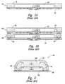
- FIG. 1Aschematically illustrates a conventional packaged microelectronic device 10 including an interposer substrate 20 and a microelectronic die 40 attached to the interposer substrate 20 .
- the microelectronic die 40has been encapsulated with a casing 30 to protect the die 40 from environmental factors.
- microelectronic devicesElectronic products require packaged microelectronic devices to have an extremely high density of components in a very limited space.
- the space available for memory devices, processors, displays, and other microelectronic componentsis quite limited in cell phones, PDAs, portable computers, and many other products.
- Reducing the size of the microelectronic device 10is difficult because high performance microelectronic devices 10 generally have more bond-pads, which result in larger ball-grid arrays and thus larger footprints.
- One technique used to increase the density of microelectronic devices 10 within a given footprintis to stack one microelectronic device 10 on top of another.
- FIG. 1Bschematically illustrates a first packaged microelectronic device 10 a attached to a second similar microelectronic device 10 b in a stacked configuration.
- the interposer substrate 20 of the first microelectronic device 10 ais coupled to the interposer substrate 20 of the second microelectronic device 10 b by large solder balls 50 .
- One drawback of the stacked devices 10 a - bis that the large solder balls 50 required to span the distance between the two interposer substrates 20 use valuable space on the interposer substrates 20 , which increases the footprint of the microelectronic devices 10 a - b.
- FIG. 2schematically illustrates another packaged microelectronic device 60 in accordance with the prior art.
- the device 60includes a first microelectronic die 70 a attached to a substrate 80 and a second microelectronic die 70 b attached to the first die 70 a .
- the first and second dies 70 a - bare electrically coupled to the substrate 80 with a plurality of wire-bonds 90
- the device 60further includes a casing 95 encapsulating the dies 70 a - b and wire-bonds 90 .
- FIG. 1Ais a partially schematic side cross-sectional view of a conventional packaged microelectronic device in accordance with the prior art.
- FIG. 1Bis a partially schematic side cross-sectional view of the packaged microelectronic device of FIG. 1A stacked on top of a second similar microelectronic device.
- FIG. 2is a partially schematic side cross-sectional view of another packaged microelectronic device in accordance with the prior art.
- FIGS. 3A-7illustrate stages of a method for manufacturing a plurality of stacked microelectronic devices in accordance with one embodiment of the invention.
- FIGS. 8-13illustrate stages of a method for manufacturing a plurality of stacked microelectronic devices in accordance with another embodiment of the invention.
- FIG. 14is a partially schematic side cross-sectional view of a microelectronic device configured in accordance with still another embodiment of the invention.
- FIGS. 15A-18illustrate stages of a method for manufacturing a plurality of stacked microelectronic devices in accordance with yet another embodiment of the invention.
- FIGS. 19 and 20illustrate stages of a method for manufacturing a plurality of stacked microelectronic devices in accordance with still yet another embodiment of the invention.
- the following disclosuredescribes several embodiments of microelectronic devices, stacked microelectronic devices, and methods for manufacturing such devices.
- One aspect of the inventionis directed toward a stacked microelectronic device assembly including a first known good packaged microelectronic device and a second known good packaged microelectronic device coupled to the first device in a stacked configuration.
- the first devicecan include a first interposer substrate with a plurality of first interposer contacts and a first die carried by and electrically coupled to the first interposer contacts.
- the first devicecan also include a first casing having a first face at the first interposer substrate and a second face opposite the first face such that the first casing encapsulates the first die and at least a portion of the first interposer substrate.
- the first devicecan further include a plurality of first through-casing interconnects at least partially encapsulated in the first casing and in contact with corresponding first interposer contacts. The first interconnects extend from the first face to the second face
- the second devicecan include a second interposer substrate with a plurality of second interposer pads and a second die carried by and electrically coupled to the second interposer substrate.
- the second devicecan also include a second casing that encapsulates the second die and at least a portion of the second interposer substrate.
- the second interposer padsare electrically coupled to the exposed portions of the corresponding first interconnects at the second face of the first casing.
- the first interconnectscan have a number of different configurations.
- the first interconnectscomprise a plurality of lead fingers attached to the first side of the first interposer substrate and projecting inwardly from a periphery of the first casing toward the first die.
- the lead fingerscan be in contact with and electrically coupled to corresponding first interposer contacts.
- the first interconnectscomprise filaments attached to and projecting from the first interposer contacts.
- the first interconnectscomprise a plurality of openings extending through the first casing and generally aligned with corresponding first interposer contacts.
- the individual openingscan be at least partially filled with a conductive material (e.g., a solder material deposited into the openings using a reflow process).
- a conductive materiale.g., a solder material deposited into the openings using a reflow process.
- the first interconnectsare at least partially aligned with a periphery of the first casing such that at least a portion of each interconnect is accessible along the periphery of the first casing. In other embodiments, however, the first interconnects are inboard of the periphery of the first casing such that the first interconnects are not accessible along the periphery.
- the second devicecan further include a plurality of second through-casing interconnects at least partially encapsulated in the second casing and in contact with corresponding second interposer contacts on the second interposer substrate.
- the second interconnectscan include features generally similar to the first interconnects described above.
- one or more additional known good packaged microelectronic devicescan be attached and electrically coupled to the second device in a stacked configuration.
- Another aspect of the inventionis directed toward methods for manufacturing microelectronic devices.
- One embodiment of such a methodincludes positioning a first known good packaged microelectronic device proximate to a second known good packaged microelectronic device.
- the first devicecan include a first interposer substrate, a first die electrically coupled to the first interposer substrate, and a plurality of electrically conductive interconnects electrically coupled to the interposer substrate.
- the first die, at least a portion of the first interposer substrate, and at least a portion of the first interconnectsare encased in a first casing.
- the first interconnectshave accessible terminals at a top portion of the first casing.
- the methodalso includes mounting the second device to the first device in a stacked configuration.
- the second devicecan include a second interposer substrate and a second die electrically coupled to the second interposer substrate.
- a second casingcovers the second die and at least a portion of the second interposer substrate.
- the terminals of the first interconnects at the top portion of the first casingare electrically coupled to corresponding interposer pads of the second interposer substrate.
- assemblyand “subassembly” are used throughout to include a variety of articles of manufacture, including, e.g., semiconductor wafers having active components, individual integrated circuit dies, packaged dies, and devices comprising two or more microfeature workpieces or components, e.g., a stacked die package.
- semiconductor wafershaving active components
- individual integrated circuit diespackaged dies
- devicescomprising two or more microfeature workpieces or components, e.g., a stacked die package.
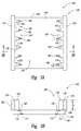
- FIGS. 3A-7illustrate stages in a method for manufacturing a plurality of stacked microelectronic devices in accordance with one embodiment of the invention. More specifically, FIG. 3A is a partially schematic, top plan view of a subassembly 100 at an initial stage of the method, and FIG. 3B is a side cross-sectional view taken substantially along line 3 B- 3 B of FIG. 3A .
- the subassembly 100includes a support member 102 , such as an interposer substrate, a printed circuit board, or another suitable structure, and a lead frame 120 on the support member.
- the support member 102includes (a) a first side 104 having a plurality of contacts 108 , (b) a second side 106 opposite the first side 104 and having a plurality of pads 110 , and (c) a plurality of traces 112 or other type of conductive lines between the contacts 108 and corresponding pads 110 or other contacts (not shown) at the second side 106 of the support member 102 .
- the contacts 108can be arranged in arrays for electrical connection to corresponding contacts on the lead frame 120 and/or one or more microelectronic dies attached to the support member 102 , as described in more detail below.
- the pads 110 at the second side 106 of the support member 102are arranged in an array corresponding to a standard JEDEC pinout.
- the support member 102may include a different number or arrangement of contacts/pads at the first side 104 and/or second side 106 .
- the lead frame 120is a self-supporting structure that generally includes a peripheral dam 122 and a plurality of lead fingers 124 projecting inwardly of the peripheral dam 122 .
- the lead fingers 124are spaced from one another by gaps 126 therebetween.
- the inner surfaces of the peripheral dam 122 and each of the lead fingers 124together form an inner periphery 128 of an opening 129 in the lead frame 120 .
- the opening 129extends through the entire thickness of the lead frame 120 .
- the lead frame 120can be formed of a metal or another suitable conductive material.
- the lead frame 120can be a conductive material that is plated with a noble metal, such as gold, silver, or palladium, or the lead frame 120 can be a non-conductive material coated with a conductive material. A portion of each lead finger 124 contacts a corresponding contact 108 on the support member 102 .
- the lead frame 120can have a different number of lead fingers 124 based, at least in part, on the configuration of the microelectronic die that is to be electrically coupled to the lead frame 120 .
- the lead fingers 124can include more complex shapes instead of the fairly simple, block-shaped lead fingers 124 shown in the illustrated embodiment.
- the peripheral dam 122 and each of the lead fingers 124have generally the same height D 1 .
- the height D 1should be greater than the height of a microelectronic die to be positioned on the support member 102 . In other embodiments, however, the height of the lead fingers 124 may be different than the height of the peripheral dam 122 .
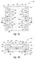
- a microelectronic die 140may be positioned within the opening 129 of the lead frame 120 .
- a plurality of lead frames 120 and dies 140can be attached to the support member 102 for manufacturing a plurality of microelectronic devices.
- the die 140can include a front or active side 142 , a back side 144 opposite the active side 142 , and integrated circuitry 146 (shown schematically). The back side 144 of the die 140 is attached to the exposed first side 104 of the support member 102 within the opening 129 .
- the die 140can also include a plurality of terminals 148 (e.g., bond-pads) arranged in an array at the active side 142 and electrically coupled to the integrated circuitry 146 .
- the terminals 148accordingly provide external contacts to provide source voltages, ground voltages, and signals to the integrated circuitry 146 in the die 140 .
- the terminals 148are adjacent to the periphery of the die 140 and electrically coupled to corresponding contacts 108 on the support member 102 by wire-bonds 150 or other types of connectors.
- the wire-bonds 150generally include a loop height that remains below the height D 1 of the lead frame 120 to ensure complete encapsulation of the wire-bonds 150 by an encapsulant, as described in more detail below.
- the die 140can have other features and/or the die can be attached and electrically coupled to the support member 102 using other arrangements, such as a flip-chip configuration (FCIP) or another suitable method.
- FCIPflip-chip configuration
- the order in which the lead frame 120 and die 140 are attached to the support member 102can be varied. In the embodiment described above, the lead frame 120 is attached to the support member 102 before the die 140 is attached to the support member. In other embodiments, however, the die 140 can be attached to the support member 102 before the lead frame 120 is attached to the support member. In still further embodiments, the lead frame 120 and the die 140 may be simultaneously attached to the support member 102 .
- an encapsulant 160may be disposed in the opening 129 after the die 140 is electrically coupled to the contacts 108 to form a casing 162 that encapsulates at least a portion of the subassembly 100 . More particularly, the exposed first side 104 of the support member 102 , the inner periphery 128 of the lead frame 120 , and the die 140 define a cavity 152 within the opening 129 that may be partially or completely filled with the encapsulant 160 to form the casing 162 . In the illustrated embodiment, the cavity 152 is completely filled with the encapsulant 160 such that an upper portion 164 of the casing 162 is substantially coplanar with an upper portion 130 of the lead fingers 124 . In other embodiments, however, the upper portion 164 of the casing 162 may be below the upper portion 130 of the lead fingers 124 as long as the die 140 and corresponding wire-bonds 150 are completely encapsulated.
- the encapsulant 160can be deposited into the opening 129 using a suitable application process, such as conventional injection molding, film molding, or other suitable process.
- the encapsulant 160is delivered to the cavity 152 and is allowed to simply fill the cavity and cover the die 140 and wire-bonds 150 . If any encapsulant 160 flows outwardly over the upper portion 130 of the lead fingers 124 , the overburden of encapsulant material can be removed by grinding, polishing, or other suitable techniques. In other embodiments, however, the flow of encapsulant 160 can be limited by use of a molding element (not shown) having a substantially flat molding surface that lies substantially flush against the upper portion 130 of the lead fingers 124 to keep the encapsulant 160 from flowing over the lead frame 120 .
- the peripheral dam 122physically connects each of the lead fingers 124 to each other and helps define the cavity 152 for receiving the encapsulant 160 as described above. Once the casing 162 is in place, however, the peripheral dam 122 is no longer needed. Accordingly, the subassembly 100 can be cut along lines A-A to remove the peripheral dam 122 and form a packaged microelectronic device 170 ( FIGS. 6A and 6B ) having a plurality of isolated lead fingers 124 spaced about a periphery of the device 170 . The subassembly 100 can be cut using a conventional wafer saw, high-pressure water jets, lasers, or the like. In other embodiments, the lines A-A can be moved slightly inward toward the die 140 such that a portion of each lead finger 124 is also removed along with the peripheral dam 122 .
- the device 170can be tested post-packaging to ensure that the device functions properly so that only known good devices undergo further processing.
- a plurality of electrical couplers 166e.g., solder balls
- the electrical couplers 166are generally attached to the device 170 after testing to ensure that the couplers are only attached to known good devices, but in some embodiments the couplers can be attached to the device before testing.
- the device 170is that the upper portion 164 of the casing 162 is substantially coplanar with the upper portion 130 of the lead fingers 124 .
- the device 170is accordingly a mechanically stable structure wherein each of the lead fingers 124 defines an electrical pathway between the pads 110 at the second side 106 of the support member 102 and the upper portion 130 of corresponding lead fingers 124 . As explained below, this feature can facilitate stacking of two or more devices 170 .
- Another feature of the device 170is that at least a portion of each lead finger 124 is accessible along a periphery of the casing 162 .
- each lead finger 124includes a front surface 132 facing toward the die 140 and a back surface 134 opposite the front surface 132 and generally aligned with the periphery of the casing 162 .
- One advantage of this featureis that the accessible back surface 134 of each lead finger 124 can provide additional contact points to facilitate testing of the device 170 .
- FIG. 7is a side cross-sectional view of a stacked microelectronic device assembly 190 including an upper microelectronic device 170 a stacked on top of a lower microelectronic device 170 b .
- the upper and lower devices 170 a and 170 bcan be generally similar to the microelectronic device 170 described above with respect to FIGS. 6A and 6B .
- the upper device 170 adiffers from the device 170 described above, however, in that the device 170 a includes an array of pads 111 a at the second side 106 of the support member 102 having a different arrangement than the array of pads 110 of the device 170 .
- the device 170 ais configured to be an “upper” device in a stacked assembly and, accordingly, the pads 111 a are arranged such that they contact corresponding lead fingers 124 of the lower device 170 b to electrically couple the upper device 170 a and lower device 170 b together.
- the upper device 170 adoes not generally include electrical couplers attached to the pads 111 a .
- the upper device 170 a and/or lower device 170 bcan have different arrangements.
- the upper device 170 acan include a plurality of pads 110 a (shown in broken lines) having an arrangement generally similar to the arrangement of pads 110 of the device 170 described above.
- the lead fingers 124 of the lower device 170 bcan include engagement portions 124 a (shown in broken lines) projecting from the front surface 132 of each lead finger 124 and configured to contact corresponding pads 110 a .
- the upper and lower device 170 a and 170 bcan include other features.
- the upper device 170 ais coupled to the lower device 170 b by attaching and electrically coupling the pads 111 a of the upper device 170 a to corresponding lead fingers 124 on the lower device 170 b .
- the second side 106 of the upper device's support member 102is in direct contact with the upper portion 164 of the lower device's casing 162 . Accordingly, the stacked assembly 190 does not include a fill material between the upper and lower devices 170 a and 170 b .
- the upper portion 164 of the casing 162may not be coplanar with the upper portion 130 of the lead fingers 124 and, accordingly, a fill material (not shown) may be deposited into a gap or cavity between the upper device 170 a and the lower device 170 b .
- the fill materiale.g., an epoxy resin or other suitable molding compound
- the fill materialcan enhance the integrity of the stacked assembly 190 and protect the components of the upper device and the lower device from moisture, chemicals, and other contaminants.
- the fill materialis an optional component.
- One advantage of the devices 170 formed using the methods described above with reference to FIGS. 3A-7is that the devices can be stacked on top of each other. Stacking microelectronic devices increases the capacity and/or performance within a given surface area or footprint. For example, when the upper microelectronic device 170 a is stacked on top of the lower microelectronic device 170 b and the lower device 170 b is attached to a circuit board or other external device, the upper microelectronic device 170 a is electrically and operably coupled to the circuit board or external device without using any more surface area on the circuit board.
- One feature of the stacked assembly 190is that both the upper and lower devices 170 a and 170 b can be tested after packaging and before stacking to ensure that they function properly before being assembled together. Throughput of stacked assemblies 190 can accordingly be increased because defective devices can be detected and excluded from the stacked assemblies 190 formed using the methods described above and each assembly will generally include only known good devices. This increases the yield of the packaging processes described above and reduces the number of devices that malfunction and/or include defects.
- Still another feature of the devices 170 described above with reference to FIGS. 3A-7is that the electrical couplers 166 are positioned inboard of the lead fingers 124 .
- An advantage of this featureis that the footprint of the stacked assembly 190 is reduced as compared with conventional stacked devices, such as the devices 10 a and 10 b illustrated in FIG. 1B where the solder balls 50 are outboard of the dies 40 . Minimizing the footprint of microelectronic devices is particularly important in cell phones, PDAs, and other electronic products where there is a constant drive to reduce the size of microelectronic components used in such devices.
- FIGS. 8-21illustrate various stages in other embodiments of methods for manufacturing stacked microelectronic devices.
- the following methods and devices formed using such methodscan have many of the same advantages as the devices 170 and the stacked assembly 190 described above with respect to FIGS. 3A-7 .
- FIG. 8is a schematic side cross-sectional view of a subassembly 200 including a plurality of microelectronic dies 220 (only three are shown) arranged in an array on a support member 202 .
- the support member 202can include an interposer substrate, a printed circuit board, or other suitable support member for carrying the dies 220 .
- the support member 202includes (a) a first side 204 having a plurality of contacts 208 , and (b) a second side 206 having a plurality of first pads 210 and a plurality of second pads 212 .
- the contacts 208can be arranged in arrays for electrical connection to corresponding terminals on the dies 220 and the first and second pads 210 and 212 can be arranged in arrays to receive a plurality of electrical couplers (e.g., solder balls) and/or other types of electrical interconnects.
- the support member 202further includes a plurality of conductive traces 214 electrically coupling the contacts 208 to corresponding first and second pads 210 and 212 .
- the first and/or second pads 210 and 212 at the second side 206 of the support member 202are arranged in an array corresponding to a standard JEDEC pinout.
- the support member 202may include a different number or arrangement of contacts/pads at the first side 204 and/or the second side 206 .
- the individual dies 220include integrated circuitry 222 (shown schematically), a front or active side 224 , a plurality of terminals 226 (e.g., bond-pads) arranged in an array at the active side 224 and electrically coupled to the integrated circuitry 222 , and a back side 228 opposite the active side 224 .
- the back sides 228 of the dies 220are attached to the support member 202 with an adhesive 230 , such as an adhesive film, epoxy, tape, paste, or other suitable material.
- a plurality of wire-bonds 232 or other types of connectorscouple the terminals 226 on the dies 220 to corresponding contacts 208 on the support member 202 .
- the dies 220have the same structure, in other embodiments, the dies 220 may have different features to perform different functions. In further embodiments, the dies 220 may be attached and electrically coupled to the support member 202 using other arrangements, such as an FCIP configuration or another suitable method.
- FIG. 9is a schematic side cross-sectional view of the subassembly 200 after attaching a plurality of interconnects or filaments 234 to the contacts 208 at the first side 204 of the support member 202 .
- the interconnects or filaments 234can include thin, flexible wires attached and electrically coupled to corresponding contacts 208 .
- the interconnects 234include relatively straight, free-standing wire-bond lines that are attached to and project away from the contacts 208 in a direction generally normal to the first side 204 of the support member 202 .
- the interconnects 234include a height H relative to the first side 204 of the support member 202 that is based, at least in part, on the desired height of the resulting packaged device.
- the interconnects 234can also include an electrical coupler 236 (e.g., a ball-shaped portion) at a distal end of each interconnect. As described in more detail below, the electrical couplers 236 can help improve joint interconnection with one or more devices that may be stacked on the dies 220 .
- the interconnects 234are generally attached to the contacts 208 after forming the wire-bonds 232 , but in some embodiments the interconnects 234 and wire-bonds 232 can be formed at the same time. In other embodiments, such as the embodiment described below with respect to FIG. 15 , the interconnects 234 can have a different arrangement and/or include different features.
- an encapsulant 240is deposited onto the support member 202 to form a plurality of casings 242 encapsulating the dies 220 , the wire-bonds 232 , and at least a portion of the interconnects 234 .
- the encapsulant 240can be deposited onto the support member 202 using a suitable application process, such as conventional injection molding, film molding, or other suitable process.
- a top portion 244 (shown in broken lines) of the casings 242can be removed to at least partially expose the electrical couplers 236 at the distal end of the interconnects 234 .
- the top portion 244 of the casings 242can be removed using a laser grinding process or another suitable process.
- a mold used during encapsulation of the subassembly 200can include cavities or recesses corresponding to the arrangement of electrical couplers 236 such that the individual electrical couplers are not encapsulated when forming the casings 242 and, therefore, a grinding or removal process is not necessary.
- the encapsulant 240can be deposited using another suitable process that leaves the electrical couplers 236 exposed after the device is removed from the mold.
- a laser drilling processcan be used after encapsulation to isolate and expose at least a portion of the interconnects 234 and a conductive material (e.g., gold) can be deposited into the resulting vias to create a plurality of conductive pads in a desired arrangement at the top portion 244 of the casing 242 .
- a redistribution structurecan then be formed at the top portion 244 to redistribute the signals from the conductive pads to a larger array of contacts.
- the subassembly 200can be cut along lines B-B to singulate a plurality of individual microelectronic devices 250 .
- the individual devices 250can be tested post-packaging to ensure that each device functions properly so that only known good devices undergo further processing.
- a plurality of electrical couplers 252e.g., solder balls
- the electrical couplers 252are generally attached to the devices 250 after testing to ensure that the couplers are only attached to known good devices, but in some embodiments the couplers can be attached to the devices before testing.
- one or more individual devices 250can be stacked together to form stacked microelectronic device assemblies.
- FIG. 13is a side cross-sectional view of a stacked microelectronic device assembly 290 including an upper microelectronic device 250 a stacked on top of a lower microelectronic device 250 b .
- the upper and lower devices 250 a and 250 bcan be generally similar to the devices 250 described above with respect to FIGS. 8-12 .
- the upper device 250 acan be coupled to the lower device 250 b by attaching the second side 206 of the upper device's support member 202 to the top portion 244 of the lower device's casing 242 with an adhesive material 260 , such as an adhesive film, epoxy, tape, paste, or other suitable material.
- the lower device's electrical couplers 236 bcan be electrically coupled to corresponding first pads 210 a on the upper device 250 a .
- each of the electrical couplers 236 bis electrically coupled to corresponding first pads 210 a with electrical connectors 262 .
- the electrical connectors 262may also physically bond (at least in part) the upper device 250 a to the lower device 250 b .
- the electrical connectors 262can include solder connections that are reflowed as is known in the art or other suitable connectors.
- a fill material 264can be deposited into the area between the upper device 250 a and the lower device 250 b and, if no additional devices are to be stacked on the upper device 250 a , over the exposed electrical couplers 236 a at the top portion 244 of the upper device 250 a .
- the fill material 264can enhance the integrity of the stacked assembly 290 and protect the components of the upper and lower devices 250 a and 250 b from moisture, chemicals, and other contaminants.
- the fill material 264can include a molding compound such as an epoxy resin. In other embodiments, the fill material 264 can include other suitable materials. Depositing the fill material 264 is an optional step that may not be included in some embodiments.
- additional microelectronic devicescan be stacked onto the upper microelectronic device 250 a by exposing the electrical couplers 236 a at the top portion 244 of the upper device 250 a , stacking one or more additional devices (not shown) onto the upper device 250 a , and electrically coupling the additional devices to the electrical couplers 236 a .
- the upper and lower devices 250 a and 250 bcan be different devices.
- the microelectronic dies 220 in the upper and lower devices 250 a and 250 bcan be the same or different types of dies and/or the upper and lower devices 250 a and 250 b can include other features.
- FIG. 14illustrates a microelectronic device 350 configured in accordance with another embodiment of the invention.
- the microelectronic device 350is generally similar to the microelectronic devices 250 described above with reference to FIGS. 8-12 . Accordingly, like reference numbers are used to refer to like components in FIGS. 8-12 and FIG. 14 .
- the device 350differs from the device 250 , however, in that the device 350 includes a interconnect 334 having a different configuration than the interconnect 234 of the device 250 . More specifically, the interconnect 334 of the device 350 includes a wire loop such that a ball portion and a stitch portion of the wire are both at the corresponding contacts 208 on the support member 202 .
- the loop-shaped interconnectcan have the height H generally similar to the interconnect 234 described above such that a top portion 335 of the interconnect 334 can be exposed at the top portion 244 of the casing 242 .
- One advantage of the loop-shaped interconnects 334is that such interconnects are generally expected to be more durable than the single-filament interconnects 234 described previously because the loop-shaped interconnects are more securely anchored to the corresponding contacts 208 and, accordingly, are less likely to bend or disconnect from the contacts during molding.
- the loop-shaped interconnects 334can provide lower inductance than the interconnects 234 .
- FIGS. 15A-18illustrate stages in yet another embodiment of a method for manufacturing a plurality of stacked microelectronic devices.
- FIG. 15Ais a partially schematic, isometric view of a subassembly 400 at an initial stage of the method.
- the subassembly 400includes a plurality of microelectronic dies 430 (shown in broken lines) arranged in an array on a support member 402 and encapsulated with a casing 462 . It will be appreciated that although only four dies 430 are shown attached to the support member 402 in the illustrated embodiment, a different number of dies 430 can be attached to the support member 402 for manufacturing a plurality of microelectronic devices.
- the subassembly 400further includes a plurality of small openings or vias 440 (i.e., “pin holes”) extending through the casing 462 to a first side 404 of the support member 402 .
- the openings 440are generally arranged in the “streets” or non-active areas between the individual dies 430 .
- the openings 440are discussed in greater detail below with reference to FIGS. 16A and 16B .
- FIG. 15Bis a side cross-sectional view taken substantially along lines 15 B- 15 B of FIG. 15A .
- the support member 402can include an interposer substrate, a printed circuit board, or other suitable support member.
- the support member 402includes (a) the first side 404 having a plurality of first contacts 408 and a plurality of second contacts 409 , (b) a second side 406 opposite the first side 404 and having a plurality of first pads 410 and a plurality of second pads 411 , and (c) a plurality of traces 412 or other type of conductive lines between the first and/or second contacts 408 and 409 and corresponding first and/or second pads 410 and 411 or other contacts (not shown) at the second side 406 of the support member 402 .
- the first and second contacts 408 and 409can be arranged in arrays for electrical connection to corresponding contacts on the dies 430 and one or more devices stacked on the packaged dies, as described in more detail below.
- the second pads 411 at the second side 406 of the support member 402are arranged in an array corresponding to a standard JEDEC pinout.
- the support member 402may include a different number or arrangement of contacts and/or pads.
- the individual microelectronic dies 430can include a front or active side 432 , a back side 434 opposite the active side 432 , and integrated circuitry 436 (shown schematically).
- the back side 434 of the dies 430can be attached to the first side 404 of the support member 402 with an adhesive (not shown).
- the dies 430can also include a plurality of terminals 438 (e.g., bond-pads) arranged in an array at the active side 432 and electrically coupled to the integrated circuitry 436 .
- the terminals 438are arranged adjacent a periphery of the dies 430 and used to electrically couple the dies 430 to the support member 402 using a chip-on-board (COB) configuration.
- COBchip-on-board
- a plurality of wire-bonds 439 or other types of connectorsextend between the terminals 438 and corresponding second contacts 409 on the support member 402 .
- the dies 430can have other features and/or the dies can be attached and electrically coupled to the support member 402 using other arrangements, such as an FCIP configuration, a board-on-chip (BOC) configuration, or another suitable configuration.
- a conductive material 442is deposited into each of the openings 440 to form a plurality of electrically conductive interconnects 444 extending through the casing 462 to corresponding first contacts 408 on the support member 402 .
- a solder ball(not shown) is placed at a top portion of each opening 440 and reflowed such that the solder generally fills the corresponding opening.
- the conductive material 442can be deposited into the openings 440 using other suitable methods.
- the subassembly 400can be cut along lines C-C to singulate a plurality of individual microelectronic devices 450 .
- FIG. 17Ais a partially schematic, isometric view of a singulated device 450
- FIG. 17Bis a side cross-sectional view taken substantially along lines 17 B- 17 B of FIG. 17A .
- the individual devices 450can be tested at this stage of the method to ensure that each device functions properly so that only known good devices undergo further processing.
- the device 450 illustrated in FIGS. 17A and 17Bis configured to be a “bottom” or “lower” device in a stacked microelectronic device and, accordingly, a plurality of electrical couplers (not shown) can be attached to corresponding second pads 411 at the second side of the support member 402 .
- the second pads 411are arranged to have a standard JEDEC pinout.
- the device 450was configured to be an “upper” device (i.e., a device stacked on one or more lower devices), the second pads 411 could have a different arrangement and/or electrical couplers may not be attached to the second pads.
- the interconnects 444are at least partially exposed at a top portion 454 and a periphery portion 452 of the device 450 .
- the exposed interconnects 444accordingly define an electrical pathway between the first and second pads 410 and 411 at the second side 406 of the support member 402 and the top portion 454 of the device 450 .
- this featurecan facilitate stacking of two or more devices 450 .
- FIG. 18is a partially schematic, isometric view of a stacked microelectronic device assembly 490 including a first microelectronic device 450 a , a second upper microelectronic device 450 b stacked on the first microelectronic device 450 a , and a third microelectronic device 450 c on the second microelectronic device 450 b .
- the devices 450 a - ccan be generally similar to the devices 450 described above with respect to FIGS. 15A-17B .
- the second device 450 bcan be coupled to the first device 450 a by attaching the first pads 410 b at the second side 406 of the second device's support member 402 to corresponding exposed portions of the first device's interconnects 444 at the top portion 454 of the first device 450 a .
- the third device 450 ccan be coupled to the second device 450 b in a generally similar manner.
- a plurality of extremely small alignment holescan be formed completely through each device 450 a - c before stacking the devices together.
- a laser beam or other suitable beam of lightcan be directed through the alignment holes in the stacked assembly 490 to ensure that the individual devices are properly aligned relative to each other so that the external electrical contacts on each device are in contact with appropriate contacts on the adjoining device(s). For example, if the beam passes completely through the stacked assembly, the alignment holes in each device are properly aligned. On the other hand, if the light does not pass completely through the stacked assembly, one or more of the devices are out of alignment. In other embodiments, other suitable methods can be used to align the individual devices 450 relative to each other in the stacked assembly 490 .
- FIGS. 19 and 20illustrate stages of a method for manufacturing a plurality of stacked microelectronic devices in accordance with still yet another embodiment of the invention. This method can include several steps that are at least generally similar to those described above with respect to FIGS. 15A-17B .
- FIG. 19is a side cross-sectional view of a microelectronic device 550 having a number of features generally similar to the devices 450 described above with reference to FIGS. 15A-17B .
- the arrangement of the die and the configuration of the interconnects in the device 550differ from the arrangement of the die 430 and the interconnects 444 in the devices 450 .
- the device 550includes a die 530 having a FCIP configuration rather than the COB configuration of the die 430 in the devices 450 described above. Moreover, the device 550 includes a plurality of interconnects 544 positioned inboard of a periphery portion 554 of the device 550 , in contrast with the interconnects 444 that are at least partially exposed about the periphery portion 452 of the devices 450 .
- the die 530 of the device 550can include an active side 532 attached to the first side 404 of the support member 402 , a back side 534 opposite the active side 532 , and integrated circuitry 536 (shown schematically).
- the die 530can also include a plurality of terminals 538 electrically coupled to the integrated circuitry 536 and attached to corresponding first contacts 508 at the first side 404 of the support member 402 .
- the first contacts 508can have a different arrangement on the support member 402 than the arrangement of first contacts 408 described previously.
- the die 530can include different features and/or can be attached to the support member 402 using a different arrangement.
- the interconnects 544extend through the casing 462 to corresponding second contacts 509 on the support member 402 .
- the interconnects 544can be formed using methods generally similar to those used to form the interconnects 444 described above.
- One particular aspect of the interconnects 544 in the illustrated embodimentis that the interconnects are arranged in laterally adjacent pairs (shown as a first interconnect 544 a and a second interconnect 544 b ) about the die 530 .
- One advantage of this featureis that it increases the number of signals that can be passed from the device 550 to an external device without substantially increasing the footprint of the device 550 .
- the interconnects 544can have different arrangements about the die (e.g., single interconnects arranged inboard of the periphery of the device 550 or more than two interconnects arranged together).
- the device 550also includes a plurality of first pads 510 and a plurality of second pads 511 at the second side 406 of the support member 402 .
- the first pads 510are arranged in an array corresponding to a standard JEDEC pinout and the second pads 511 are arranged in a pattern generally corresponding to the arrangement of the second contacts 509 at the first side 404 of the support member 402 to facilitate stacking of two more devices 550 .
- a plurality of electrical couplers 566e.g., solder balls
- FIG. 20is a side cross-sectional view of a stacked microelectronic device assembly 590 including an upper microelectronic device 550 a stacked on top of a lower microelectronic device 550 b .
- the upper and lower devices 550 a and 550 bcan be generally similar to the microelectronic device 550 described above with respect to FIG. 19 .
- the upper device 550 adiffers from the device 550 described above, however, in that the device 550 a is configured to be an “upper” device in a stacked assembly and, accordingly, the upper device 550 a generally does not include electrical couplers attached to the first pads 510 a.
- the upper device 550 ais coupled to the lower device 550 b by attaching and electrically coupling the second pads 511 of the upper device 550 a to corresponding interconnects 544 on the lower device 550 b .
- the second side 406 of the upper device's support member 402is in direct contact with the top portion of the lower device's casing.
- a plurality of electrical couplersmay be used to couple the upper device's second pads 511 to corresponding interconnects 544 on the lower device 550 b .
- a filler material(not shown) may also be deposited into the resulting gap between the upper device 550 a and the lower device 550 b.
- One feature of the stacked assemblies 190 / 290 / 490 / 590 described above with respect to FIGS. 7, 13, 18, and 20 , respectively,is that the individual microelectronic devices 170 / 250 / 450 / 550 in each assembly include through-packaging interconnects that are at least partially exposed at a top portion of each device's casing to facilitate stacking of the individual devices without requiring intermediate structures or large solder balls between the stacked devices.
- An advantage of this featureis that it can reduce the vertical profiles of the stacked assemblies 190 / 290 / 490 / 590 . Devices with smaller vertical profiles are extremely desirable in cell phones, PDAs, and other electronic devices where there is a constant drive to reduce the size of microelectronic components used in such devices.
- one or more additional microelectronic devicesmay be stacked on the devices in each of the embodiments described above to form stacked devices including a greater number of stacked units.
- one or more additional microelectronic diesmay be stacked on the dies in each of the microelectronic devices described above to form individual microelectronic devices having more than one die.
- the microelectronic devicesmay also include a number of other different features and/or arrangements. Aspects of the invention described in the context of particular embodiments may be combined or eliminated in other embodiments.
Landscapes
- Engineering & Computer Science (AREA)
- Microelectronics & Electronic Packaging (AREA)
- Power Engineering (AREA)
- Computer Hardware Design (AREA)
- Condensed Matter Physics & Semiconductors (AREA)
- General Physics & Mathematics (AREA)
- Physics & Mathematics (AREA)
- Manufacturing & Machinery (AREA)
- Lead Frames For Integrated Circuits (AREA)
- Wire Bonding (AREA)
- Testing Or Measuring Of Semiconductors Or The Like (AREA)
- Encapsulation Of And Coatings For Semiconductor Or Solid State Devices (AREA)
- Testing Of Individual Semiconductor Devices (AREA)
Abstract
Description
Claims (23)
Priority Applications (3)
| Application Number | Priority Date | Filing Date | Title |
|---|---|---|---|
| US13/898,004US9362141B2 (en) | 2006-02-28 | 2013-05-20 | Microelectronic devices, stacked microelectronic devices, and methods for manufacturing such devices |
| US15/144,699US9768121B2 (en) | 2006-02-28 | 2016-05-02 | Microelectronic devices, stacked microelectronic devices, and methods for manufacturing such devices |
| US15/702,225US10211114B2 (en) | 2006-02-28 | 2017-09-12 | Microelectronic devices, stacked microelectronic devices, and methods for manufacturing such devices |
Applications Claiming Priority (6)
| Application Number | Priority Date | Filing Date | Title |
|---|---|---|---|
| SG200601271-0ASG135074A1 (en) | 2006-02-28 | 2006-02-28 | Microelectronic devices, stacked microelectronic devices, and methods for manufacturing such devices |
| SG200601271-0 | 2006-02-28 | ||
| SG200601271 | 2006-02-28 | ||
| US11/414,864US7671459B2 (en) | 2006-02-08 | 2006-05-01 | Microelectronic devices, stacked microelectronic devices, and methods for manufacturing such devices |
| US12/689,624US8450839B2 (en) | 2006-02-28 | 2010-01-19 | Microelectronic devices, stacked microelectronic devices, and methods for manufacturing such devices |
| US13/898,004US9362141B2 (en) | 2006-02-28 | 2013-05-20 | Microelectronic devices, stacked microelectronic devices, and methods for manufacturing such devices |
Related Parent Applications (1)
| Application Number | Title | Priority Date | Filing Date |
|---|---|---|---|
| US12/689,624DivisionUS8450839B2 (en) | 2006-02-28 | 2010-01-19 | Microelectronic devices, stacked microelectronic devices, and methods for manufacturing such devices |
Related Child Applications (1)
| Application Number | Title | Priority Date | Filing Date |
|---|---|---|---|
| US15/144,699DivisionUS9768121B2 (en) | 2006-02-28 | 2016-05-02 | Microelectronic devices, stacked microelectronic devices, and methods for manufacturing such devices |
Publications (2)
| Publication Number | Publication Date |
|---|---|
| US20130252354A1 US20130252354A1 (en) | 2013-09-26 |
| US9362141B2true US9362141B2 (en) | 2016-06-07 |
Family
ID=38333198
Family Applications (5)
| Application Number | Title | Priority Date | Filing Date |
|---|---|---|---|
| US11/414,864ActiveUS7671459B2 (en) | 2006-02-08 | 2006-05-01 | Microelectronic devices, stacked microelectronic devices, and methods for manufacturing such devices |
| US12/689,624ActiveUS8450839B2 (en) | 2006-02-28 | 2010-01-19 | Microelectronic devices, stacked microelectronic devices, and methods for manufacturing such devices |
| US13/898,004ActiveUS9362141B2 (en) | 2006-02-28 | 2013-05-20 | Microelectronic devices, stacked microelectronic devices, and methods for manufacturing such devices |
| US15/144,699ActiveUS9768121B2 (en) | 2006-02-28 | 2016-05-02 | Microelectronic devices, stacked microelectronic devices, and methods for manufacturing such devices |
| US15/702,225ActiveUS10211114B2 (en) | 2006-02-28 | 2017-09-12 | Microelectronic devices, stacked microelectronic devices, and methods for manufacturing such devices |
Family Applications Before (2)
| Application Number | Title | Priority Date | Filing Date |
|---|---|---|---|
| US11/414,864ActiveUS7671459B2 (en) | 2006-02-08 | 2006-05-01 | Microelectronic devices, stacked microelectronic devices, and methods for manufacturing such devices |
| US12/689,624ActiveUS8450839B2 (en) | 2006-02-28 | 2010-01-19 | Microelectronic devices, stacked microelectronic devices, and methods for manufacturing such devices |
Family Applications After (2)
| Application Number | Title | Priority Date | Filing Date |
|---|---|---|---|
| US15/144,699ActiveUS9768121B2 (en) | 2006-02-28 | 2016-05-02 | Microelectronic devices, stacked microelectronic devices, and methods for manufacturing such devices |
| US15/702,225ActiveUS10211114B2 (en) | 2006-02-28 | 2017-09-12 | Microelectronic devices, stacked microelectronic devices, and methods for manufacturing such devices |
Country Status (6)
| Country | Link |
|---|---|
| US (5) | US7671459B2 (en) |
| EP (1) | EP2005472B1 (en) |
| JP (1) | JP5088583B2 (en) |
| KR (1) | KR101022907B1 (en) |
| SG (1) | SG135074A1 (en) |
| WO (1) | WO2007101251A2 (en) |
Families Citing this family (166)
| Publication number | Priority date | Publication date | Assignee | Title |
|---|---|---|---|---|
| US7215018B2 (en) | 2004-04-13 | 2007-05-08 | Vertical Circuits, Inc. | Stacked die BGA or LGA component assembly |
| JP2005317861A (en)* | 2004-04-30 | 2005-11-10 | Toshiba Corp | Semiconductor device and manufacturing method thereof |
| KR101313391B1 (en) | 2004-11-03 | 2013-10-01 | 테세라, 인코포레이티드 | Stacked packaging improvements |
| KR100618892B1 (en)* | 2005-04-13 | 2006-09-01 | 삼성전자주식회사 | Semiconductor package achieves fan-out structure through wire bonding |
| SG130055A1 (en) | 2005-08-19 | 2007-03-20 | Micron Technology Inc | Microelectronic devices, stacked microelectronic devices, and methods for manufacturing microelectronic devices |
| SG130066A1 (en) | 2005-08-26 | 2007-03-20 | Micron Technology Inc | Microelectronic device packages, stacked microelectronic device packages, and methods for manufacturing microelectronic devices |
| US8058101B2 (en) | 2005-12-23 | 2011-11-15 | Tessera, Inc. | Microelectronic packages and methods therefor |
| SG135074A1 (en) | 2006-02-28 | 2007-09-28 | Micron Technology Inc | Microelectronic devices, stacked microelectronic devices, and methods for manufacturing such devices |
| US7550834B2 (en)* | 2006-06-29 | 2009-06-23 | Sandisk Corporation | Stacked, interconnected semiconductor packages |
| US7615409B2 (en)* | 2006-06-29 | 2009-11-10 | Sandisk Corporation | Method of stacking and interconnecting semiconductor packages via electrical connectors extending between adjoining semiconductor packages |
| SG139573A1 (en)* | 2006-07-17 | 2008-02-29 | Micron Technology Inc | Microelectronic packages with leadframes, including leadframes configured for stacked die packages, and associated systems and methods |
| KR100832845B1 (en)* | 2006-10-03 | 2008-05-28 | 삼성전자주식회사 | Semiconductor package structure and manufacturing method thereof |
| US8513789B2 (en) | 2006-10-10 | 2013-08-20 | Tessera, Inc. | Edge connect wafer level stacking with leads extending along edges |
| US7829438B2 (en) | 2006-10-10 | 2010-11-09 | Tessera, Inc. | Edge connect wafer level stacking |
| US7901989B2 (en) | 2006-10-10 | 2011-03-08 | Tessera, Inc. | Reconstituted wafer level stacking |
| KR100850072B1 (en)* | 2006-11-03 | 2008-08-04 | 동부일렉트로닉스 주식회사 | Implanter having a compensation function of a cut angle of a semiconductor wafer and method thereof |
| US7952195B2 (en) | 2006-12-28 | 2011-05-31 | Tessera, Inc. | Stacked packages with bridging traces |
| US8445325B2 (en)* | 2007-05-04 | 2013-05-21 | Stats Chippac, Ltd. | Package-in-package using through-hole via die on saw streets |
| US7723159B2 (en) | 2007-05-04 | 2010-05-25 | Stats Chippac, Ltd. | Package-on-package using through-hole via die on saw streets |
| US8106491B2 (en) | 2007-05-16 | 2012-01-31 | Micron Technology, Inc. | Methods of forming stacked semiconductor devices with a leadframe and associated assemblies |
| SG148056A1 (en) | 2007-05-17 | 2008-12-31 | Micron Technology Inc | Integrated circuit packages, methods of forming integrated circuit packages, and methods of assembling intgrated circuit packages |
| US8723332B2 (en) | 2007-06-11 | 2014-05-13 | Invensas Corporation | Electrically interconnected stacked die assemblies |
| US8367471B2 (en)* | 2007-06-15 | 2013-02-05 | Micron Technology, Inc. | Semiconductor assemblies, stacked semiconductor devices, and methods of manufacturing semiconductor assemblies and stacked semiconductor devices |
| US20110024890A1 (en)* | 2007-06-29 | 2011-02-03 | Stats Chippac, Ltd. | Stackable Package By Using Internal Stacking Modules |
| SG148901A1 (en)* | 2007-07-09 | 2009-01-29 | Micron Technology Inc | Packaged semiconductor assemblies and methods for manufacturing such assemblies |
| JP5215605B2 (en) | 2007-07-17 | 2013-06-19 | ラピスセミコンダクタ株式会社 | Manufacturing method of semiconductor device |
| US7893545B2 (en)* | 2007-07-18 | 2011-02-22 | Infineon Technologies Ag | Semiconductor device |
| JP5572089B2 (en) | 2007-07-27 | 2014-08-13 | テッセラ,インコーポレイテッド | Reconfigured wafer stack packaging with pad extension after application |
| US8551815B2 (en) | 2007-08-03 | 2013-10-08 | Tessera, Inc. | Stack packages using reconstituted wafers |
| US8043895B2 (en) | 2007-08-09 | 2011-10-25 | Tessera, Inc. | Method of fabricating stacked assembly including plurality of stacked microelectronic elements |
| WO2009035849A2 (en) | 2007-09-10 | 2009-03-19 | Vertical Circuits, Inc. | Semiconductor die mount by conformal die coating |
| KR20090027325A (en)* | 2007-09-12 | 2009-03-17 | 삼성전자주식회사 | Semiconductor package and semiconductor module having same |
| US7915724B2 (en)* | 2007-09-28 | 2011-03-29 | Stats Chippac Ltd. | Integrated circuit packaging system with base structure device |
| US7618849B2 (en)* | 2007-10-22 | 2009-11-17 | Broadcom Corporation | Integrated circuit package with etched leadframe for package-on-package interconnects |
| US7800208B2 (en)* | 2007-10-26 | 2010-09-21 | Infineon Technologies Ag | Device with a plurality of semiconductor chips |
| US8536692B2 (en)* | 2007-12-12 | 2013-09-17 | Stats Chippac Ltd. | Mountable integrated circuit package system with mountable integrated circuit die |
| CN101999167B (en) | 2008-03-12 | 2013-07-17 | 伊文萨思公司 | Support mounted electrically interconnected die assembly |
| US7863755B2 (en)* | 2008-03-19 | 2011-01-04 | Stats Chippac Ltd. | Package-on-package system with via Z-interconnections |
| US7919871B2 (en)* | 2008-03-21 | 2011-04-05 | Stats Chippac Ltd. | Integrated circuit package system for stackable devices |
| US20090243069A1 (en)* | 2008-03-26 | 2009-10-01 | Zigmund Ramirez Camacho | Integrated circuit package system with redistribution |
| US7863159B2 (en) | 2008-06-19 | 2011-01-04 | Vertical Circuits, Inc. | Semiconductor die separation method |
| US9153517B2 (en) | 2008-05-20 | 2015-10-06 | Invensas Corporation | Electrical connector between die pad and z-interconnect for stacked die assemblies |
| JP5639052B2 (en) | 2008-06-16 | 2014-12-10 | テッセラ,インコーポレイテッド | Edge stacking at wafer level |
| US9293385B2 (en)* | 2008-07-30 | 2016-03-22 | Stats Chippac Ltd. | RDL patterning with package on package system |
| US8130512B2 (en)* | 2008-11-18 | 2012-03-06 | Stats Chippac Ltd. | Integrated circuit package system and method of package stacking |
| US8916452B2 (en)* | 2008-11-23 | 2014-12-23 | Stats Chippac, Ltd. | Semiconductor device and method of forming WLCSP using wafer sections containing multiple die |
| US7851894B1 (en)* | 2008-12-23 | 2010-12-14 | Amkor Technology, Inc. | System and method for shielding of package on package (PoP) assemblies |
| WO2010104610A2 (en) | 2009-03-13 | 2010-09-16 | Tessera Technologies Hungary Kft. | Stacked microelectronic assemblies having vias extending through bond pads |
| WO2010151578A2 (en) | 2009-06-26 | 2010-12-29 | Vertical Circuits, Inc. | Electrical interconnect for die stacked in zig-zag configuration |
| WO2011056668A2 (en) | 2009-10-27 | 2011-05-12 | Vertical Circuits, Inc. | Selective die electrical insulation additive process |
| TWI544604B (en) | 2009-11-04 | 2016-08-01 | 英維瑟斯公司 | Stacked die assembly having reduced stress electrical interconnects |
| US20110147867A1 (en)* | 2009-12-23 | 2011-06-23 | Everspin Technologies, Inc. | Method of vertically mounting an integrated circuit |
| US8466997B2 (en)* | 2009-12-31 | 2013-06-18 | Stmicroelectronics Pte Ltd. | Fan-out wafer level package for an optical sensor and method of manufacture thereof |
| US8536716B1 (en)* | 2009-12-31 | 2013-09-17 | Micron Technology, Inc. | Supply voltage or ground connections for integrated circuit device |
| US20110156240A1 (en)* | 2009-12-31 | 2011-06-30 | Stmicroelectronics Asia Pacific Pte. Ltd. | Reliable large die fan-out wafer level package and method of manufacture |
| US8884422B2 (en)* | 2009-12-31 | 2014-11-11 | Stmicroelectronics Pte Ltd. | Flip-chip fan-out wafer level package for package-on-package applications, and method of manufacture |
| US8502394B2 (en)* | 2009-12-31 | 2013-08-06 | Stmicroelectronics Pte Ltd. | Multi-stacked semiconductor dice scale package structure and method of manufacturing same |
| US8436255B2 (en)* | 2009-12-31 | 2013-05-07 | Stmicroelectronics Pte Ltd. | Fan-out wafer level package with polymeric layer for high reliability |
| KR20110085481A (en)* | 2010-01-20 | 2011-07-27 | 삼성전자주식회사 | Laminated Semiconductor Packages |
| US8338934B2 (en)* | 2010-03-18 | 2012-12-25 | Marvell World Trade Ltd. | Embedded die with protective interposer |
| US8618654B2 (en) | 2010-07-20 | 2013-12-31 | Marvell World Trade Ltd. | Structures embedded within core material and methods of manufacturing thereof |
| US8796137B2 (en)* | 2010-06-24 | 2014-08-05 | Stats Chippac, Ltd. | Semiconductor device and method of forming RDL along sloped side surface of semiconductor die for z-direction interconnect |
| KR20120005341A (en)* | 2010-07-08 | 2012-01-16 | 주식회사 하이닉스반도체 | Semiconductor Chips & Packages |
| US8482111B2 (en) | 2010-07-19 | 2013-07-09 | Tessera, Inc. | Stackable molded microelectronic packages |
| US9159708B2 (en) | 2010-07-19 | 2015-10-13 | Tessera, Inc. | Stackable molded microelectronic packages with area array unit connectors |
| US8553420B2 (en) | 2010-10-19 | 2013-10-08 | Tessera, Inc. | Enhanced stacked microelectronic assemblies with central contacts and improved thermal characteristics |
| KR101075241B1 (en) | 2010-11-15 | 2011-11-01 | 테세라, 인코포레이티드 | Microelectronic package with terminals in dielectric member |
| TWI538071B (en) | 2010-11-16 | 2016-06-11 | 星科金朋有限公司 | Integrated circuit packaging system with connection structure and method of manufacture thereof |
| US20120146206A1 (en) | 2010-12-13 | 2012-06-14 | Tessera Research Llc | Pin attachment |
| US8466544B2 (en) | 2011-02-25 | 2013-06-18 | Stats Chippac, Ltd. | Semiconductor device and method of forming interposer and opposing build-up interconnect structure with connecting conductive TMV for electrical interconnect of Fo-WLCSP |
| US8952516B2 (en) | 2011-04-21 | 2015-02-10 | Tessera, Inc. | Multiple die stacking for two or more die |
| US8970028B2 (en) | 2011-12-29 | 2015-03-03 | Invensas Corporation | Embedded heat spreader for package with multiple microelectronic elements and face-down connection |
| US8633576B2 (en) | 2011-04-21 | 2014-01-21 | Tessera, Inc. | Stacked chip-on-board module with edge connector |
| US8304881B1 (en) | 2011-04-21 | 2012-11-06 | Tessera, Inc. | Flip-chip, face-up and face-down wirebond combination package |
| US9013033B2 (en) | 2011-04-21 | 2015-04-21 | Tessera, Inc. | Multiple die face-down stacking for two or more die |
| US8928153B2 (en) | 2011-04-21 | 2015-01-06 | Tessera, Inc. | Flip-chip, face-up and face-down centerbond memory wirebond assemblies |
| KR101128063B1 (en)* | 2011-05-03 | 2012-04-23 | 테세라, 인코포레이티드 | Package-on-package assembly with wire bonds to encapsulation surface |
| US8618659B2 (en) | 2011-05-03 | 2013-12-31 | Tessera, Inc. | Package-on-package assembly with wire bonds to encapsulation surface |
| US8633100B2 (en) | 2011-06-17 | 2014-01-21 | Stats Chippac Ltd. | Method of manufacturing integrated circuit packaging system with support structure |
| CN102891116B (en)* | 2011-07-20 | 2015-06-10 | 讯芯电子科技(中山)有限公司 | Embedded component packaging structure and manufacturing method |
| CN107845619B (en)* | 2011-07-22 | 2022-01-18 | 超大规模集成电路技术有限责任公司 | Stacked die semiconductor package |
| US8872318B2 (en) | 2011-08-24 | 2014-10-28 | Tessera, Inc. | Through interposer wire bond using low CTE interposer with coarse slot apertures |
| US9142502B2 (en)* | 2011-08-31 | 2015-09-22 | Zhiwei Gong | Semiconductor device packaging having pre-encapsulation through via formation using drop-in signal conduits |
| US8916421B2 (en) | 2011-08-31 | 2014-12-23 | Freescale Semiconductor, Inc. | Semiconductor device packaging having pre-encapsulation through via formation using lead frames with attached signal conduits |
| US9013037B2 (en) | 2011-09-14 | 2015-04-21 | Stmicroelectronics Pte Ltd. | Semiconductor package with improved pillar bump process and structure |
| US8703538B2 (en) | 2011-09-23 | 2014-04-22 | Stats Chippac Ltd. | Integrated circuit packaging system with external wire connection and method of manufacture thereof |
| US8836136B2 (en) | 2011-10-17 | 2014-09-16 | Invensas Corporation | Package-on-package assembly with wire bond vias |
| US8916481B2 (en) | 2011-11-02 | 2014-12-23 | Stmicroelectronics Pte Ltd. | Embedded wafer level package for 3D and package-on-package applications, and method of manufacture |
| US8779601B2 (en) | 2011-11-02 | 2014-07-15 | Stmicroelectronics Pte Ltd | Embedded wafer level package for 3D and package-on-package applications, and method of manufacture |
| US8597983B2 (en) | 2011-11-18 | 2013-12-03 | Freescale Semiconductor, Inc. | Semiconductor device packaging having substrate with pre-encapsulation through via formation |
| US20130154106A1 (en)* | 2011-12-14 | 2013-06-20 | Broadcom Corporation | Stacked Packaging Using Reconstituted Wafers |
| US8623711B2 (en)* | 2011-12-15 | 2014-01-07 | Stats Chippac Ltd. | Integrated circuit packaging system with package-on-package and method of manufacture thereof |
| US9219029B2 (en) | 2011-12-15 | 2015-12-22 | Stats Chippac Ltd. | Integrated circuit packaging system with terminals and method of manufacture thereof |
| US8629567B2 (en) | 2011-12-15 | 2014-01-14 | Stats Chippac Ltd. | Integrated circuit packaging system with contacts and method of manufacture thereof |
| US8946757B2 (en) | 2012-02-17 | 2015-02-03 | Invensas Corporation | Heat spreading substrate with embedded interconnects |
| US8372741B1 (en)* | 2012-02-24 | 2013-02-12 | Invensas Corporation | Method for package-on-package assembly with wire bonds to encapsulation surface |
| US9349706B2 (en) | 2012-02-24 | 2016-05-24 | Invensas Corporation | Method for package-on-package assembly with wire bonds to encapsulation surface |
| US9275976B2 (en)* | 2012-02-24 | 2016-03-01 | Broadcom Corporation | System-in-package with integrated socket |
| US8835228B2 (en) | 2012-05-22 | 2014-09-16 | Invensas Corporation | Substrate-less stackable package with wire-bond interconnect |
| ITVI20120145A1 (en)* | 2012-06-15 | 2013-12-16 | St Microelectronics Srl | COMPREHENSIVE STRUCTURE OF ENCLOSURE INCLUDING SIDE CONNECTIONS |
| US9391008B2 (en)* | 2012-07-31 | 2016-07-12 | Invensas Corporation | Reconstituted wafer-level package DRAM |
| US9502390B2 (en) | 2012-08-03 | 2016-11-22 | Invensas Corporation | BVA interposer |
| US8975738B2 (en) | 2012-11-12 | 2015-03-10 | Invensas Corporation | Structure for microelectronic packaging with terminals on dielectric mass |
| US8878353B2 (en) | 2012-12-20 | 2014-11-04 | Invensas Corporation | Structure for microelectronic packaging with bond elements to encapsulation surface |
| US9136254B2 (en) | 2013-02-01 | 2015-09-15 | Invensas Corporation | Microelectronic package having wire bond vias and stiffening layer |
| CN104051284B (en)* | 2013-03-15 | 2017-05-24 | 环旭电子股份有限公司 | Electronic packaging structure and manufacture method thereof |
| US9312198B2 (en)* | 2013-03-15 | 2016-04-12 | Intel Deutschland Gmbh | Chip package-in-package and method thereof |
| ITMI20130473A1 (en) | 2013-03-28 | 2014-09-29 | St Microelectronics Srl | METHOD FOR MANUFACTURING ELECTRONIC DEVICES |
| US8883563B1 (en) | 2013-07-15 | 2014-11-11 | Invensas Corporation | Fabrication of microelectronic assemblies having stack terminals coupled by connectors extending through encapsulation |
| US9034696B2 (en) | 2013-07-15 | 2015-05-19 | Invensas Corporation | Microelectronic assemblies having reinforcing collars on connectors extending through encapsulation |
| US9023691B2 (en) | 2013-07-15 | 2015-05-05 | Invensas Corporation | Microelectronic assemblies with stack terminals coupled by connectors extending through encapsulation |
| US9167710B2 (en) | 2013-08-07 | 2015-10-20 | Invensas Corporation | Embedded packaging with preformed vias |
| US9685365B2 (en) | 2013-08-08 | 2017-06-20 | Invensas Corporation | Method of forming a wire bond having a free end |
| US20150076714A1 (en) | 2013-09-16 | 2015-03-19 | Invensas Corporation | Microelectronic element with bond elements to encapsulation surface |
| US9082753B2 (en) | 2013-11-12 | 2015-07-14 | Invensas Corporation | Severing bond wire by kinking and twisting |
| US9087815B2 (en) | 2013-11-12 | 2015-07-21 | Invensas Corporation | Off substrate kinking of bond wire |
| US9379074B2 (en) | 2013-11-22 | 2016-06-28 | Invensas Corporation | Die stacks with one or more bond via arrays of wire bond wires and with one or more arrays of bump interconnects |
| US9263394B2 (en) | 2013-11-22 | 2016-02-16 | Invensas Corporation | Multiple bond via arrays of different wire heights on a same substrate |
| US9583456B2 (en) | 2013-11-22 | 2017-02-28 | Invensas Corporation | Multiple bond via arrays of different wire heights on a same substrate |
| CN104752491A (en)* | 2013-12-30 | 2015-07-01 | 晟碟半导体(上海)有限公司 | Spacer layer for semiconductor device and semiconductor device |
| US9870946B2 (en)* | 2013-12-31 | 2018-01-16 | Taiwan Semiconductor Manufacturing Company, Ltd. | Wafer level package structure and method of forming same |
| US9583411B2 (en) | 2014-01-17 | 2017-02-28 | Invensas Corporation | Fine pitch BVA using reconstituted wafer with area array accessible for testing |
| US9214454B2 (en) | 2014-03-31 | 2015-12-15 | Invensas Corporation | Batch process fabrication of package-on-package microelectronic assemblies |
| US9257396B2 (en)* | 2014-05-22 | 2016-02-09 | Invensas Corporation | Compact semiconductor package and related methods |
| US10381326B2 (en) | 2014-05-28 | 2019-08-13 | Invensas Corporation | Structure and method for integrated circuits packaging with increased density |
| US9646917B2 (en) | 2014-05-29 | 2017-05-09 | Invensas Corporation | Low CTE component with wire bond interconnects |
| US9412714B2 (en) | 2014-05-30 | 2016-08-09 | Invensas Corporation | Wire bond support structure and microelectronic package including wire bonds therefrom |
| US10319607B2 (en)* | 2014-08-22 | 2019-06-11 | Taiwan Semiconductor Manufacturing Company, Ltd. | Package-on-package structure with organic interposer |
| US9627367B2 (en)* | 2014-11-21 | 2017-04-18 | Micron Technology, Inc. | Memory devices with controllers under memory packages and associated systems and methods |
| US9812337B2 (en) | 2014-12-03 | 2017-11-07 | Taiwan Semiconductor Manufacturing Company, Ltd. | Integrated circuit package pad and methods of forming |
| US9735084B2 (en) | 2014-12-11 | 2017-08-15 | Invensas Corporation | Bond via array for thermal conductivity |
| US9888579B2 (en) | 2015-03-05 | 2018-02-06 | Invensas Corporation | Pressing of wire bond wire tips to provide bent-over tips |
| US9950898B2 (en)* | 2015-03-24 | 2018-04-24 | Kabushiki Kaisha Toshiba | Semiconductor device, inverter circuit, driving device, vehicle, and elevator |
| US9502372B1 (en) | 2015-04-30 | 2016-11-22 | Invensas Corporation | Wafer-level packaging using wire bond wires in place of a redistribution layer |
| US9761554B2 (en) | 2015-05-07 | 2017-09-12 | Invensas Corporation | Ball bonding metal wire bond wires to metal pads |
| DE102015008503A1 (en)* | 2015-07-03 | 2017-01-05 | TE Connectivity Sensors Germany GmbH | Electrical component and manufacturing method for producing such an electrical component |
| US9825002B2 (en) | 2015-07-17 | 2017-11-21 | Invensas Corporation | Flipped die stack |
| US9490195B1 (en) | 2015-07-17 | 2016-11-08 | Invensas Corporation | Wafer-level flipped die stacks with leadframes or metal foil interconnects |
| US9871019B2 (en) | 2015-07-17 | 2018-01-16 | Invensas Corporation | Flipped die stack assemblies with leadframe interconnects |
| US10490528B2 (en)* | 2015-10-12 | 2019-11-26 | Invensas Corporation | Embedded wire bond wires |
| US9490222B1 (en) | 2015-10-12 | 2016-11-08 | Invensas Corporation | Wire bond wires for interference shielding |
| US10332854B2 (en) | 2015-10-23 | 2019-06-25 | Invensas Corporation | Anchoring structure of fine pitch bva |
| US10181457B2 (en) | 2015-10-26 | 2019-01-15 | Invensas Corporation | Microelectronic package for wafer-level chip scale packaging with fan-out |
| US10043779B2 (en) | 2015-11-17 | 2018-08-07 | Invensas Corporation | Packaged microelectronic device for a package-on-package device |
| US9659848B1 (en) | 2015-11-18 | 2017-05-23 | Invensas Corporation | Stiffened wires for offset BVA |
| US9508691B1 (en) | 2015-12-16 | 2016-11-29 | Invensas Corporation | Flipped die stacks with multiple rows of leadframe interconnects |
| US9984992B2 (en) | 2015-12-30 | 2018-05-29 | Invensas Corporation | Embedded wire bond wires for vertical integration with separate surface mount and wire bond mounting surfaces |
| US10566310B2 (en) | 2016-04-11 | 2020-02-18 | Invensas Corporation | Microelectronic packages having stacked die and wire bond interconnects |
| US9704812B1 (en)* | 2016-05-06 | 2017-07-11 | Atmel Corporation | Double-sided electronic package |
| US9595511B1 (en) | 2016-05-12 | 2017-03-14 | Invensas Corporation | Microelectronic packages and assemblies with improved flyby signaling operation |
| US9728524B1 (en) | 2016-06-30 | 2017-08-08 | Invensas Corporation | Enhanced density assembly having microelectronic packages mounted at substantial angle to board |
| US9935075B2 (en) | 2016-07-29 | 2018-04-03 | Invensas Corporation | Wire bonding method and apparatus for electromagnetic interference shielding |
| CN107785334B (en)* | 2016-08-24 | 2019-11-01 | 矽品精密工业股份有限公司 | Electronic package structure and method for fabricating the same |
| US10299368B2 (en) | 2016-12-21 | 2019-05-21 | Invensas Corporation | Surface integrated waveguides and circuit structures therefor |
| TWI637476B (en)* | 2017-02-14 | 2018-10-01 | 來揚科技股份有限公司 | Dual-chip package structure |
| CN207781947U (en)* | 2017-03-10 | 2018-08-28 | 唐虞企业股份有限公司 | Connector with a locking member |
| EP3486944A4 (en)* | 2017-09-14 | 2019-05-22 | Shenzhen Goodix Technology Co., Ltd. | CHIP ENCLOSURE STRUCTURE AND METHOD AND ELECTRONIC DEVICE |
| US11227859B2 (en) | 2017-09-30 | 2022-01-18 | Intel Corporation | Stacked package with electrical connections created using high throughput additive manufacturing |
| US10636775B2 (en)* | 2017-10-27 | 2020-04-28 | Taiwan Semiconductor Manufacturing Co., Ltd. | Package structure and manufacturing method thereof |
| US10475771B2 (en)* | 2018-01-24 | 2019-11-12 | Micron Technology, Inc. | Semiconductor device with an electrically-coupled protection mechanism and associated systems, devices, and methods |
| CN110943050B (en)* | 2018-09-21 | 2023-08-15 | 中兴通讯股份有限公司 | Packaging structure and stacked packaging structure |
| US11081392B2 (en)* | 2018-09-28 | 2021-08-03 | Taiwan Semiconductor Manufacturing Co., Ltd. | Dicing method for stacked semiconductor devices |
| DE102019124181B4 (en) | 2018-09-28 | 2023-06-15 | Taiwan Semiconductor Manufacturing Co., Ltd. | Singulation method for stacked semiconductor components and stacked semiconductor device |
| CN109841535B (en)* | 2019-01-31 | 2022-04-15 | 合肥鑫晟光电科技有限公司 | Array substrate and preparation method thereof, display panel, and display device |
| US11721657B2 (en) | 2019-06-14 | 2023-08-08 | Stmicroelectronics Pte Ltd | Wafer level chip scale package having varying thicknesses |
| US11121105B2 (en)* | 2019-07-06 | 2021-09-14 | Amkor Technology Singapore Holding Pte. Ltd. | Semiconductor devices and methods of manufacturing semiconductor devices |
Citations (162)
| Publication number | Priority date | Publication date | Assignee | Title |
|---|---|---|---|---|
| US4012579A (en) | 1975-02-21 | 1977-03-15 | Allen-Bradley Company | Encapsulated microcircuit package and method for assembly thereof |
| US4862245A (en) | 1985-04-18 | 1989-08-29 | International Business Machines Corporation | Package semiconductor chip |
| US5107328A (en) | 1991-02-13 | 1992-04-21 | Micron Technology, Inc. | Packaging means for a semiconductor die having particular shelf structure |
| US5128831A (en) | 1991-10-31 | 1992-07-07 | Micron Technology, Inc. | High-density electronic package comprising stacked sub-modules which are electrically interconnected by solder-filled vias |
| US5138434A (en) | 1991-01-22 | 1992-08-11 | Micron Technology, Inc. | Packaging for semiconductor logic devices |
| US5140404A (en) | 1990-10-24 | 1992-08-18 | Micron Technology, Inc. | Semiconductor device manufactured by a method for attaching a semiconductor die to a leadframe using a thermoplastic covered carrier tape |
| US5252857A (en) | 1991-08-05 | 1993-10-12 | International Business Machines Corporation | Stacked DCA memory chips |
| US5252853A (en) | 1991-09-19 | 1993-10-12 | Mitsubishi Denki Kabushiki Kaisha | Packaged semiconductor device having tab tape and particular power distribution lead structure |
| US5304842A (en) | 1990-10-24 | 1994-04-19 | Micron Technology, Inc. | Dissimilar adhesive die attach for semiconductor devices |
| US5471369A (en) | 1993-07-09 | 1995-11-28 | Fujitsu Limited | Semiconductor device having a plurality of semiconductor chips |
| US5475918A (en) | 1993-10-01 | 1995-12-19 | Electroplating Engineers Of Japan Ltd. | Method of preventing deformation of lead frames |
| US5518957A (en) | 1991-10-10 | 1996-05-21 | Samsung Electronics Co., Ltd. | Method for making a thin profile semiconductor package |
| US5536969A (en) | 1992-12-18 | 1996-07-16 | Yamaichi Electronics Co., Ltd. | IC carrier |
| US5583371A (en) | 1994-10-12 | 1996-12-10 | Kabushiki Kaisha Toshiba | Resin-sealed semiconductor device capable of improving in heat radiation characteristics of resin-sealed semiconductor elements |
| US5593927A (en) | 1993-10-14 | 1997-01-14 | Micron Technology, Inc. | Method for packaging semiconductor dice |
| US5663593A (en) | 1995-10-17 | 1997-09-02 | National Semiconductor Corporation | Ball grid array package with lead frame |
| US5665651A (en) | 1993-07-15 | 1997-09-09 | Kabushiki Kaisha Toshiba | Process for encapsulating a semiconductor device and lead frame |
| US5677566A (en) | 1995-05-08 | 1997-10-14 | Micron Technology, Inc. | Semiconductor chip package |
| US5696033A (en) | 1995-08-16 | 1997-12-09 | Micron Technology, Inc. | Method for packaging a semiconductor die |
| US5715593A (en) | 1996-01-30 | 1998-02-10 | Nec Corporation | Method of making plastic-packaged semiconductor integrated circuit |
| US5726493A (en) | 1994-06-13 | 1998-03-10 | Fujitsu Limited | Semiconductor device and semiconductor device unit having ball-grid-array type package structure |
| US5729049A (en) | 1996-03-19 | 1998-03-17 | Micron Technology, Inc. | Tape under frame for conventional-type IC package assembly |
| US5739585A (en) | 1995-11-27 | 1998-04-14 | Micron Technology, Inc. | Single piece package for semiconductor die |
| US5744827A (en) | 1995-11-28 | 1998-04-28 | Samsung Electronics Co., Ltd. | Three dimensional stack package device having exposed coupling lead portions and vertical interconnection elements |
| USD394844S (en) | 1997-04-25 | 1998-06-02 | Micron Technology, Inc. | Temporary package for semiconductor dice |
| US5815000A (en) | 1991-06-04 | 1998-09-29 | Micron Technology, Inc. | Method for testing semiconductor dice with conventionally sized temporary packages |
| US5847455A (en) | 1995-11-07 | 1998-12-08 | Vlsi Technology, Inc. | Molded leadframe ball grid array |
| USD402638S (en) | 1997-04-25 | 1998-12-15 | Micron Technology, Inc. | Temporary package for semiconductor dice |
| US5851845A (en) | 1995-12-18 | 1998-12-22 | Micron Technology, Inc. | Process for packaging a semiconductor die using dicing and testing |
| US5866939A (en) | 1996-01-21 | 1999-02-02 | Anam Semiconductor Inc. | Lead end grid array semiconductor package |
| US5866953A (en) | 1996-05-24 | 1999-02-02 | Micron Technology, Inc. | Packaged die on PCB with heat sink encapsulant |
| US5879965A (en) | 1997-06-19 | 1999-03-09 | Micron Technology, Inc. | Plastic lead frames for semiconductor devices, packages including same, and methods of fabrication |
| US5883426A (en) | 1996-04-18 | 1999-03-16 | Nec Corporation | Stack module |
| US5891753A (en) | 1997-01-24 | 1999-04-06 | Micron Technology, Inc. | Method and apparatus for packaging flip chip bare die on printed circuit boards |
| US5891797A (en) | 1997-10-20 | 1999-04-06 | Micron Technology, Inc. | Method of forming a support structure for air bridge wiring of an integrated circuit |
| US5893726A (en) | 1997-12-15 | 1999-04-13 | Micron Technology, Inc. | Semiconductor package with pre-fabricated cover and method of fabrication |
| US5933713A (en) | 1998-04-06 | 1999-08-03 | Micron Technology, Inc. | Method of forming overmolded chip scale package and resulting product |
| US5938956A (en) | 1996-09-10 | 1999-08-17 | Micron Technology, Inc. | Circuit and method for heating an adhesive to package or rework a semiconductor die |
| US5946553A (en) | 1991-06-04 | 1999-08-31 | Micron Technology, Inc. | Process for manufacturing a semiconductor package with bi-substrate die |
| US5956236A (en) | 1997-11-25 | 1999-09-21 | Micron Technology, Inc. | Integrated circuit package support system |
| US5958100A (en) | 1993-06-03 | 1999-09-28 | Micron Technology, Inc. | Process of making a glass semiconductor package |
| US5973393A (en) | 1996-12-20 | 1999-10-26 | Lsi Logic Corporation | Apparatus and method for stackable molded lead frame ball grid array packaging of integrated circuits |
| US5973396A (en) | 1996-02-16 | 1999-10-26 | Micron Technology, Inc. | Surface mount IC using silicon vias in an area array format or same size as die array |
| US5986209A (en) | 1997-07-09 | 1999-11-16 | Micron Technology, Inc. | Package stack via bottom leaded plastic (BLP) packaging |
| US5989941A (en) | 1997-12-12 | 1999-11-23 | Micron Technology, Inc. | Encapsulated integrated circuit packaging |
| US5990566A (en) | 1998-05-20 | 1999-11-23 | Micron Technology, Inc. | High density semiconductor package |
| US5994784A (en) | 1997-12-18 | 1999-11-30 | Micron Technology, Inc. | Die positioning in integrated circuit packaging |
| US6008070A (en) | 1998-05-21 | 1999-12-28 | Micron Technology, Inc. | Wafer level fabrication and assembly of chip scale packages |
| USRE36469E (en) | 1988-09-30 | 1999-12-28 | Micron Technology, Inc. | Packaging for semiconductor logic devices |
| US6020629A (en) | 1998-06-05 | 2000-02-01 | Micron Technology, Inc. | Stacked semiconductor package and method of fabrication |
| US6025728A (en) | 1997-04-25 | 2000-02-15 | Micron Technology, Inc. | Semiconductor package with wire bond protective member |
| US6028365A (en) | 1998-03-30 | 2000-02-22 | Micron Technology, Inc. | Integrated circuit package and method of fabrication |
| US6046496A (en) | 1997-11-04 | 2000-04-04 | Micron Technology Inc | Chip package |
| US6048744A (en) | 1997-09-15 | 2000-04-11 | Micron Technology, Inc. | Integrated circuit package alignment feature |
| US6049125A (en) | 1997-12-29 | 2000-04-11 | Micron Technology, Inc. | Semiconductor package with heat sink and method of fabrication |
| US6048755A (en) | 1998-11-12 | 2000-04-11 | Micron Technology, Inc. | Method for fabricating BGA package using substrate with patterned solder mask open in die attach area |
| US6051887A (en)* | 1998-08-28 | 2000-04-18 | Medtronic, Inc. | Semiconductor stacked device for implantable medical apparatus |
| US6051878A (en) | 1997-03-10 | 2000-04-18 | Micron Technology, Inc. | Method of constructing stacked packages |
| US6060778A (en) | 1997-05-17 | 2000-05-09 | Hyundai Electronics Industries Co. Ltd. | Ball grid array package |
| US6066514A (en) | 1996-10-18 | 2000-05-23 | Micron Technology, Inc. | Adhesion enhanced semiconductor die for mold compound packaging |
| US6072233A (en) | 1998-05-04 | 2000-06-06 | Micron Technology, Inc. | Stackable ball grid array package |
| US6072236A (en) | 1996-03-07 | 2000-06-06 | Micron Technology, Inc. | Micromachined chip scale package |
| US6075284A (en) | 1998-06-30 | 2000-06-13 | Hyundai Electronics Industries Co., Ltd. | Stack package |
| US6075288A (en) | 1998-06-08 | 2000-06-13 | Micron Technology, Inc. | Semiconductor package having interlocking heat sinks and method of fabrication |
| US6089920A (en) | 1998-05-04 | 2000-07-18 | Micron Technology, Inc. | Modular die sockets with flexible interconnects for packaging bare semiconductor die |
| US6094058A (en) | 1991-06-04 | 2000-07-25 | Micron Technology, Inc. | Temporary semiconductor package having dense array external contacts |
| US6097087A (en) | 1997-10-31 | 2000-08-01 | Micron Technology, Inc. | Semiconductor package including flex circuit, interconnects and dense array external contacts |
| US6101100A (en) | 1996-07-23 | 2000-08-08 | International Business Machines Corporation | Multi-electronic device package |
| US6103547A (en) | 1997-01-17 | 2000-08-15 | Micron Technology, Inc. | High speed IC package configuration |
| US6107122A (en) | 1997-08-04 | 2000-08-22 | Micron Technology, Inc. | Direct die contact (DDC) semiconductor package |
| US6107680A (en) | 1995-01-04 | 2000-08-22 | Micron Technology, Inc. | Packaging for bare dice employing EMR-sensitive adhesives |
| US6117382A (en) | 1998-02-05 | 2000-09-12 | Micron Technology, Inc. | Method for encasing array packages |
| US6117710A (en) | 1997-02-11 | 2000-09-12 | National Semiconductor Corporation | Plastic package with exposed die and method of making same |
| US6133068A (en) | 1997-10-06 | 2000-10-17 | Micron Technology, Inc. | Increasing the gap between a lead frame and a semiconductor die |
| US6137162A (en) | 1998-05-12 | 2000-10-24 | Hyundai Electronics Industries Co., Ltd. | Chip stack package |
| WO2000068996A1 (en) | 1999-05-07 | 2000-11-16 | Seagate Technology Llc | Surface mount ic stacking method and device |
| US6148509A (en) | 1997-04-07 | 2000-11-21 | Micron Technology, Inc. | Method for supporting an integrated circuit die |
| US6150710A (en) | 1998-08-20 | 2000-11-21 | Micron Technology, Inc. | Transverse hybrid LOC package |
| US6153924A (en) | 1998-02-23 | 2000-11-28 | Micron Technology, Inc. | Multilayered lead frame for semiconductor package |
| US6159764A (en) | 1997-07-02 | 2000-12-12 | Micron Technology, Inc. | Varied-thickness heat sink for integrated circuit (IC) packages and method of fabricating IC packages |
| US6172419B1 (en) | 1998-02-24 | 2001-01-09 | Micron Technology, Inc. | Low profile ball grid array package |
| US6175149B1 (en) | 1998-02-13 | 2001-01-16 | Micron Technology, Inc. | Mounting multiple semiconductor dies in a package |
| US6184465B1 (en) | 1998-11-12 | 2001-02-06 | Micron Technology, Inc. | Semiconductor package |
| US6198172B1 (en) | 1997-02-20 | 2001-03-06 | Micron Technology, Inc. | Semiconductor chip package |
| US6208020B1 (en) | 1999-02-24 | 2001-03-27 | Matsushita Electronics Corporation | Leadframe for use in manufacturing a resin-molded semiconductor device |
| US6208519B1 (en) | 1999-08-31 | 2001-03-27 | Micron Technology, Inc. | Thermally enhanced semiconductor package |
| US6210992B1 (en) | 1999-08-31 | 2001-04-03 | Micron Technology, Inc. | Controlling packaging encapsulant leakage |
| US6215175B1 (en) | 1998-07-06 | 2001-04-10 | Micron Technology, Inc. | Semiconductor package having metal foil die mounting plate |
| US6212767B1 (en) | 1999-08-31 | 2001-04-10 | Micron Technology, Inc. | Assembling a stacked die package |
| US6225689B1 (en) | 1998-08-21 | 2001-05-01 | Micron Technology, Inc. | Low profile multi-IC chip package connector |
| US6229202B1 (en) | 2000-01-10 | 2001-05-08 | Micron Technology, Inc. | Semiconductor package having downset leadframe for reducing package bow |
| US6228687B1 (en) | 1999-06-28 | 2001-05-08 | Micron Technology, Inc. | Wafer-level package and methods of fabricating |
| US6228548B1 (en) | 1998-02-27 | 2001-05-08 | Micron Technology, Inc. | Method of making a multichip semiconductor package |
| US6232229B1 (en) | 1999-11-19 | 2001-05-15 | Micron Technology, Inc. | Microelectronic device fabricating method, integrated circuit, and intermediate construction |
| US6235554B1 (en) | 1995-11-27 | 2001-05-22 | Micron Technology, Inc. | Method for fabricating stackable chip scale semiconductor package |
| US6246110B1 (en) | 1998-07-06 | 2001-06-12 | Micron Technology, Inc. | Downset lead frame for semiconductor packages |
| KR20010064907A (en) | 1999-12-20 | 2001-07-11 | 마이클 디. 오브라이언 | wire bonding method and semiconductor package using it |
| US6261865B1 (en) | 1998-10-06 | 2001-07-17 | Micron Technology, Inc. | Multi chip semiconductor package and method of construction |
| US6277671B1 (en) | 1998-10-20 | 2001-08-21 | Micron Technology, Inc. | Methods of forming integrated circuit packages |
| US6277704B1 (en) | 2000-05-24 | 2001-08-21 | Micron Technology, Inc. | Microelectronic device fabricating method, method of forming a pair of conductive device components of different base widths from a common deposited conductive layer |
| US6281577B1 (en) | 1996-06-28 | 2001-08-28 | Pac Tech-Packaging Technologies Gmbh | Chips arranged in plurality of planes and electrically connected to one another |
| US6284571B1 (en) | 1997-07-02 | 2001-09-04 | Micron Technology, Inc. | Lead frame assemblies with voltage reference plane and IC packages including same |
| US6291894B1 (en) | 1998-08-31 | 2001-09-18 | Micron Technology, Inc. | Method and apparatus for a semiconductor package for vertical surface mounting |
| US6294839B1 (en) | 1999-08-30 | 2001-09-25 | Micron Technology, Inc. | Apparatus and methods of packaging and testing die |
| US6297547B1 (en) | 1998-02-13 | 2001-10-02 | Micron Technology Inc. | Mounting multiple semiconductor dies in a package |
| US6297543B1 (en) | 1998-12-16 | 2001-10-02 | Hyundai Electronics Industries Co., Ltd. | Chip scale package |
| US6303985B1 (en) | 1998-11-12 | 2001-10-16 | Micron Technology, Inc. | Semiconductor lead frame and package with stiffened mounting paddle |
| US6303981B1 (en) | 1999-09-01 | 2001-10-16 | Micron Technology, Inc. | Semiconductor package having stacked dice and leadframes and method of fabrication |
| US6303469B1 (en) | 2000-06-07 | 2001-10-16 | Micron Technology, Inc. | Thin microelectronic substrates and methods of manufacture |
| US6310390B1 (en) | 1999-04-08 | 2001-10-30 | Micron Technology, Inc. | BGA package and method of fabrication |
| US6316285B1 (en) | 1998-09-02 | 2001-11-13 | Micron Technology, Inc. | Passivation layer for packaged integrated circuits |
| US6314639B1 (en) | 1998-02-23 | 2001-11-13 | Micron Technology, Inc. | Chip scale package with heat spreader and method of manufacture |
| US6326244B1 (en) | 1998-09-03 | 2001-12-04 | Micron Technology, Inc. | Method of making a cavity ball grid array apparatus |
| US6326698B1 (en) | 2000-06-08 | 2001-12-04 | Micron Technology, Inc. | Semiconductor devices having protective layers thereon through which contact pads are exposed and stereolithographic methods of fabricating such semiconductor devices |
| US6326687B1 (en) | 1998-09-01 | 2001-12-04 | Micron Technology, Inc. | IC package with dual heat spreaders |
| US6329705B1 (en) | 1998-05-20 | 2001-12-11 | Micron Technology, Inc. | Leadframes including offsets extending from a major plane thereof, packaged semiconductor devices including same, and method of designing and fabricating such leadframes |
| US6329220B1 (en) | 1999-11-23 | 2001-12-11 | Micron Technology, Inc. | Packages for semiconductor die |
| US6331453B1 (en) | 1999-12-16 | 2001-12-18 | Micron Technology, Inc. | Method for fabricating semiconductor packages using mold tooling fixture with flash control cavities |
| US6331221B1 (en) | 1998-04-15 | 2001-12-18 | Micron Technology, Inc. | Process for providing electrical connection between a semiconductor die and a semiconductor die receiving member |
| US6337510B1 (en) | 2000-11-17 | 2002-01-08 | Walsin Advanced Electronics Ltd | Stackable QFN semiconductor package |
| US6339254B1 (en) | 1998-09-01 | 2002-01-15 | Texas Instruments Incorporated | Stacked flip-chip integrated circuit assemblage |
| US6344976B1 (en) | 1997-04-07 | 2002-02-05 | Micron Technology, Inc. | Interdigitated leads-over-chip lead frame device and method for supporting an integrated circuit die |
| US20020027273A1 (en) | 2000-09-04 | 2002-03-07 | Siliconware Precision Industries Co., Ltd. | Semiconductor package and fabricating method thereof |
| US6359342B1 (en)* | 2000-12-05 | 2002-03-19 | Siliconware Precision Industries Co., Ltd. | Flip-chip bumping structure with dedicated test pads on semiconductor chip and method of fabricating the same |
| US6403398B2 (en) | 1996-03-27 | 2002-06-11 | Oki Electric Industry Co, Ltd. | Semiconductor device, manufacturing method thereof and aggregate type semiconductor device |
| US6451624B1 (en) | 1998-06-05 | 2002-09-17 | Micron Technology, Inc. | Stackable semiconductor package having conductive layer and insulating layers and method of fabrication |
| US6498393B2 (en) | 1999-12-27 | 2002-12-24 | Matsushita Electric Industrial Co., Ltd. | Semiconductor device and method for the fabrication thereof |
| US6501184B1 (en) | 1999-05-20 | 2002-12-31 | Amkor Technology, Inc. | Semiconductor package and method for manufacturing the same |
| US6518659B1 (en) | 2000-05-08 | 2003-02-11 | Amkor Technology, Inc. | Stackable package having a cavity and a lid for an electronic device |
| US6516516B1 (en) | 1995-06-12 | 2003-02-11 | Hyundai Electronics Industries Co., Ltd. | Semiconductor chip package having clip-type outlead and fabrication method of same |
| US6548376B2 (en) | 2001-08-30 | 2003-04-15 | Micron Technology, Inc. | Methods of thinning microelectronic workpieces |
| US6548757B1 (en) | 2000-08-28 | 2003-04-15 | Micron Technology, Inc. | Microelectronic device assemblies having a shielded input and methods for manufacturing and operating such microelectronic device assemblies |
| US6552910B1 (en) | 2000-06-28 | 2003-04-22 | Micron Technology, Inc. | Stacked-die assemblies with a plurality of microelectronic devices and methods of manufacture |
| US6560117B2 (en) | 2000-06-28 | 2003-05-06 | Micron Technology, Inc. | Packaged microelectronic die assemblies and methods of manufacture |
| US20030104653A1 (en) | 2000-06-28 | 2003-06-05 | Farnworth Warren M. | Recessed encapsulated microelectronic devices and methods for formation |
| US20030102546A1 (en)* | 2001-04-17 | 2003-06-05 | Lee Teck Kheng | Method and apparatus for package reduction in stacked chip and board assemblies |
| US6607937B1 (en) | 2000-08-23 | 2003-08-19 | Micron Technology, Inc. | Stacked microelectronic dies and methods for stacking microelectronic dies |
| JP2003529921A (en) | 2000-02-18 | 2003-10-07 | インセップ テクノロジーズ インコーポレイテッド | Method and apparatus for powering a microprocessor with integrated thermal and EMI management |
| JP2004031650A (en) | 2002-06-26 | 2004-01-29 | Sony Corp | Leadless package and semiconductor device |
| US20040026773A1 (en) | 2002-08-08 | 2004-02-12 | Koon Eng Meow | Packaged microelectronic components |
| JP2004047702A (en) | 2002-07-11 | 2004-02-12 | Toshiba Corp | Semiconductor device stack module |
| US6740964B2 (en) | 2000-11-17 | 2004-05-25 | Oki Electric Industry Co., Ltd. | Semiconductor package for three-dimensional mounting, fabrication method thereof, and semiconductor device |
| US20040113270A1 (en) | 2002-08-29 | 2004-06-17 | Harry Hedler | Semiconductor component having a compliant buffer layer |
| US6778406B2 (en)* | 1993-11-16 | 2004-08-17 | Formfactor, Inc. | Resilient contact structures for interconnecting electronic devices |
| US6825568B2 (en) | 2002-12-13 | 2004-11-30 | Advanced Semiconductor Engineering, Inc. | Flip chip package structure and flip chip device with area bump |
| US20040262734A1 (en)* | 2003-06-30 | 2004-12-30 | Cheol-Joon Yoo | Stack type ball grid array package and method for manufacturing the same |
| US20050019484A1 (en) | 1999-11-10 | 2005-01-27 | Denglas Technologies, L.L.C. | Niobium oxide-based layers for thin film optical coatings and processes for producing the same |
| US20050026327A1 (en) | 2002-04-15 | 2005-02-03 | Micron Technology, Inc. | Semiconductor integrated circuit package having electrically disconnected solder balls for mounting |
| US20050046000A1 (en) | 2003-08-29 | 2005-03-03 | Seng Eric Tan Swee | Invertible microfeature device packages and associated methods |
| WO2005022591A2 (en) | 2003-08-26 | 2005-03-10 | Advanced Interconnect Technologies Limited | Reversible leadless package and methods of making and using same |
| US6876066B2 (en) | 2001-08-29 | 2005-04-05 | Micron Technology, Inc. | Packaged microelectronic devices and methods of forming same |
| KR20050059621A (en) | 2003-12-15 | 2005-06-21 | 삼성전자주식회사 | Nest fixture used for manufacturing stacked semiconductor chip package |
| US20050194674A1 (en)* | 2004-03-02 | 2005-09-08 | Jochen Thomas | Integrated circuit with re-route layer and stacked die assembly |
| US6951982B2 (en) | 2002-11-22 | 2005-10-04 | Micron Technology, Inc. | Packaged microelectronic component assemblies |
| US20050224928A1 (en) | 1996-10-25 | 2005-10-13 | Hinkle S D | Multi-part lead frame with dissimilar materials |
| JP2005317861A (en) | 2004-04-30 | 2005-11-10 | Toshiba Corp | Semiconductor device and manufacturing method thereof |
| US20060019484A1 (en) | 2004-07-23 | 2006-01-26 | Industrial Technology Research Institute | Wafer-leveled chip packaging structure and method thereof |
| US20060097377A1 (en)* | 2004-11-09 | 2006-05-11 | Han-Shin Youn | Flip chip bonding structure using non-conductive adhesive and related fabrication method |
| US7185426B1 (en) | 2002-05-01 | 2007-03-06 | Amkor Technology, Inc. | Method of manufacturing a semiconductor package |
| US20070148822A1 (en)* | 2005-12-23 | 2007-06-28 | Tessera, Inc. | Microelectronic packages and methods therefor |
| US20070181989A1 (en) | 2006-02-08 | 2007-08-09 | Micron Technology, Inc. | Microelectronic devices, stacked microelectronic devices, and methods for manufacturing such devices |
| US7462861B2 (en) | 2004-04-28 | 2008-12-09 | Cree, Inc. | LED bonding structures and methods of fabricating LED bonding structures |
Family Cites Families (5)
| Publication number | Priority date | Publication date | Assignee | Title |
|---|---|---|---|---|
| US20010030370A1 (en)* | 1990-09-24 | 2001-10-18 | Khandros Igor Y. | Microelectronic assembly having encapsulated wire bonding leads |
| JP4239310B2 (en)* | 1998-09-01 | 2009-03-18 | ソニー株式会社 | Manufacturing method of semiconductor device |
| US20020127771A1 (en)* | 2001-03-12 | 2002-09-12 | Salman Akram | Multiple die package |
| US7312101B2 (en)* | 2003-04-22 | 2007-12-25 | Micron Technology, Inc. | Packaged microelectronic devices and methods for packaging microelectronic devices |
| US7023700B2 (en)* | 2003-12-24 | 2006-04-04 | Super Talent Electronics, Inc. | Heat sink riveted to memory module with upper slots and open bottom edge for air flow |
- 2006
- 2006-02-28SGSG200601271-0Apatent/SG135074A1/enunknown
- 2006-05-01USUS11/414,864patent/US7671459B2/enactiveActive
- 2007
- 2007-02-28JPJP2008557488Apatent/JP5088583B2/enactiveActive
- 2007-02-28KRKR1020087023595Apatent/KR101022907B1/enactiveActive
- 2007-02-28WOPCT/US2007/062981patent/WO2007101251A2/enactiveApplication Filing
- 2007-02-28EPEP07757642.9Apatent/EP2005472B1/enactiveActive
- 2010
- 2010-01-19USUS12/689,624patent/US8450839B2/enactiveActive
- 2013
- 2013-05-20USUS13/898,004patent/US9362141B2/enactiveActive
- 2016
- 2016-05-02USUS15/144,699patent/US9768121B2/enactiveActive
- 2017
- 2017-09-12USUS15/702,225patent/US10211114B2/enactiveActive
Patent Citations (188)
| Publication number | Priority date | Publication date | Assignee | Title |
|---|---|---|---|---|
| US4012579A (en) | 1975-02-21 | 1977-03-15 | Allen-Bradley Company | Encapsulated microcircuit package and method for assembly thereof |
| US4862245A (en) | 1985-04-18 | 1989-08-29 | International Business Machines Corporation | Package semiconductor chip |
| USRE36469E (en) | 1988-09-30 | 1999-12-28 | Micron Technology, Inc. | Packaging for semiconductor logic devices |
| US5140404A (en) | 1990-10-24 | 1992-08-18 | Micron Technology, Inc. | Semiconductor device manufactured by a method for attaching a semiconductor die to a leadframe using a thermoplastic covered carrier tape |
| US5304842A (en) | 1990-10-24 | 1994-04-19 | Micron Technology, Inc. | Dissimilar adhesive die attach for semiconductor devices |
| US5138434A (en) | 1991-01-22 | 1992-08-11 | Micron Technology, Inc. | Packaging for semiconductor logic devices |
| US5107328A (en) | 1991-02-13 | 1992-04-21 | Micron Technology, Inc. | Packaging means for a semiconductor die having particular shelf structure |
| US6020624A (en) | 1991-06-04 | 2000-02-01 | Micron Technology, Inc. | Semiconductor package with bi-substrate die |
| US6094058A (en) | 1991-06-04 | 2000-07-25 | Micron Technology, Inc. | Temporary semiconductor package having dense array external contacts |
| US5946553A (en) | 1991-06-04 | 1999-08-31 | Micron Technology, Inc. | Process for manufacturing a semiconductor package with bi-substrate die |
| US5815000A (en) | 1991-06-04 | 1998-09-29 | Micron Technology, Inc. | Method for testing semiconductor dice with conventionally sized temporary packages |
| US5252857A (en) | 1991-08-05 | 1993-10-12 | International Business Machines Corporation | Stacked DCA memory chips |
| US5252853A (en) | 1991-09-19 | 1993-10-12 | Mitsubishi Denki Kabushiki Kaisha | Packaged semiconductor device having tab tape and particular power distribution lead structure |
| US5518957A (en) | 1991-10-10 | 1996-05-21 | Samsung Electronics Co., Ltd. | Method for making a thin profile semiconductor package |
| US5128831A (en) | 1991-10-31 | 1992-07-07 | Micron Technology, Inc. | High-density electronic package comprising stacked sub-modules which are electrically interconnected by solder-filled vias |
| US5536969A (en) | 1992-12-18 | 1996-07-16 | Yamaichi Electronics Co., Ltd. | IC carrier |
| US5958100A (en) | 1993-06-03 | 1999-09-28 | Micron Technology, Inc. | Process of making a glass semiconductor package |
| US5471369A (en) | 1993-07-09 | 1995-11-28 | Fujitsu Limited | Semiconductor device having a plurality of semiconductor chips |
| US5665651A (en) | 1993-07-15 | 1997-09-09 | Kabushiki Kaisha Toshiba | Process for encapsulating a semiconductor device and lead frame |
| US5475918A (en) | 1993-10-01 | 1995-12-19 | Electroplating Engineers Of Japan Ltd. | Method of preventing deformation of lead frames |
| US5593927A (en) | 1993-10-14 | 1997-01-14 | Micron Technology, Inc. | Method for packaging semiconductor dice |
| US6778406B2 (en)* | 1993-11-16 | 2004-08-17 | Formfactor, Inc. | Resilient contact structures for interconnecting electronic devices |
| US5726493A (en) | 1994-06-13 | 1998-03-10 | Fujitsu Limited | Semiconductor device and semiconductor device unit having ball-grid-array type package structure |
| US5583371A (en) | 1994-10-12 | 1996-12-10 | Kabushiki Kaisha Toshiba | Resin-sealed semiconductor device capable of improving in heat radiation characteristics of resin-sealed semiconductor elements |
| US6107680A (en) | 1995-01-04 | 2000-08-22 | Micron Technology, Inc. | Packaging for bare dice employing EMR-sensitive adhesives |
| US5677566A (en) | 1995-05-08 | 1997-10-14 | Micron Technology, Inc. | Semiconductor chip package |
| US6516516B1 (en) | 1995-06-12 | 2003-02-11 | Hyundai Electronics Industries Co., Ltd. | Semiconductor chip package having clip-type outlead and fabrication method of same |
| US5696033A (en) | 1995-08-16 | 1997-12-09 | Micron Technology, Inc. | Method for packaging a semiconductor die |
| US5663593A (en) | 1995-10-17 | 1997-09-02 | National Semiconductor Corporation | Ball grid array package with lead frame |
| US5847455A (en) | 1995-11-07 | 1998-12-08 | Vlsi Technology, Inc. | Molded leadframe ball grid array |
| US6235554B1 (en) | 1995-11-27 | 2001-05-22 | Micron Technology, Inc. | Method for fabricating stackable chip scale semiconductor package |
| US5739585A (en) | 1995-11-27 | 1998-04-14 | Micron Technology, Inc. | Single piece package for semiconductor die |
| US5744827A (en) | 1995-11-28 | 1998-04-28 | Samsung Electronics Co., Ltd. | Three dimensional stack package device having exposed coupling lead portions and vertical interconnection elements |
| US5851845A (en) | 1995-12-18 | 1998-12-22 | Micron Technology, Inc. | Process for packaging a semiconductor die using dicing and testing |
| US5866939A (en) | 1996-01-21 | 1999-02-02 | Anam Semiconductor Inc. | Lead end grid array semiconductor package |
| US5715593A (en) | 1996-01-30 | 1998-02-10 | Nec Corporation | Method of making plastic-packaged semiconductor integrated circuit |
| US6028356A (en) | 1996-01-30 | 2000-02-22 | Nec Corporation | Plastic-packaged semiconductor integrated circuit |
| US5973396A (en) | 1996-02-16 | 1999-10-26 | Micron Technology, Inc. | Surface mount IC using silicon vias in an area array format or same size as die array |
| US6072236A (en) | 1996-03-07 | 2000-06-06 | Micron Technology, Inc. | Micromachined chip scale package |
| US6124634A (en) | 1996-03-07 | 2000-09-26 | Micron Technology, Inc. | Micromachined chip scale package |
| US5729049A (en) | 1996-03-19 | 1998-03-17 | Micron Technology, Inc. | Tape under frame for conventional-type IC package assembly |
| US6215177B1 (en) | 1996-03-19 | 2001-04-10 | Micron Technology, Inc. | Tape under frame for conventional-type IC package assembly |
| US6403398B2 (en) | 1996-03-27 | 2002-06-11 | Oki Electric Industry Co, Ltd. | Semiconductor device, manufacturing method thereof and aggregate type semiconductor device |
| US5883426A (en) | 1996-04-18 | 1999-03-16 | Nec Corporation | Stack module |
| US5866953A (en) | 1996-05-24 | 1999-02-02 | Micron Technology, Inc. | Packaged die on PCB with heat sink encapsulant |
| US6281577B1 (en) | 1996-06-28 | 2001-08-28 | Pac Tech-Packaging Technologies Gmbh | Chips arranged in plurality of planes and electrically connected to one another |
| US6101100A (en) | 1996-07-23 | 2000-08-08 | International Business Machines Corporation | Multi-electronic device package |
| US5938956A (en) | 1996-09-10 | 1999-08-17 | Micron Technology, Inc. | Circuit and method for heating an adhesive to package or rework a semiconductor die |
| US6066514A (en) | 1996-10-18 | 2000-05-23 | Micron Technology, Inc. | Adhesion enhanced semiconductor die for mold compound packaging |
| US20050224928A1 (en) | 1996-10-25 | 2005-10-13 | Hinkle S D | Multi-part lead frame with dissimilar materials |
| US5973393A (en) | 1996-12-20 | 1999-10-26 | Lsi Logic Corporation | Apparatus and method for stackable molded lead frame ball grid array packaging of integrated circuits |
| US6103547A (en) | 1997-01-17 | 2000-08-15 | Micron Technology, Inc. | High speed IC package configuration |
| US5891753A (en) | 1997-01-24 | 1999-04-06 | Micron Technology, Inc. | Method and apparatus for packaging flip chip bare die on printed circuit boards |
| US5898224A (en) | 1997-01-24 | 1999-04-27 | Micron Technology, Inc. | Apparatus for packaging flip chip bare die on printed circuit boards |
| US6117710A (en) | 1997-02-11 | 2000-09-12 | National Semiconductor Corporation | Plastic package with exposed die and method of making same |
| US6198172B1 (en) | 1997-02-20 | 2001-03-06 | Micron Technology, Inc. | Semiconductor chip package |
| US6979895B2 (en) | 1997-03-10 | 2005-12-27 | Micron Technology, Inc. | Semiconductor assembly of stacked substrates and multiple semiconductor dice |
| US6051878A (en) | 1997-03-10 | 2000-04-18 | Micron Technology, Inc. | Method of constructing stacked packages |
| US6148509A (en) | 1997-04-07 | 2000-11-21 | Micron Technology, Inc. | Method for supporting an integrated circuit die |
| US6344976B1 (en) | 1997-04-07 | 2002-02-05 | Micron Technology, Inc. | Interdigitated leads-over-chip lead frame device and method for supporting an integrated circuit die |
| USD402638S (en) | 1997-04-25 | 1998-12-15 | Micron Technology, Inc. | Temporary package for semiconductor dice |
| USD394844S (en) | 1997-04-25 | 1998-06-02 | Micron Technology, Inc. | Temporary package for semiconductor dice |
| US6025728A (en) | 1997-04-25 | 2000-02-15 | Micron Technology, Inc. | Semiconductor package with wire bond protective member |
| US6060778A (en) | 1997-05-17 | 2000-05-09 | Hyundai Electronics Industries Co. Ltd. | Ball grid array package |
| US5879965A (en) | 1997-06-19 | 1999-03-09 | Micron Technology, Inc. | Plastic lead frames for semiconductor devices, packages including same, and methods of fabrication |
| US6159764A (en) | 1997-07-02 | 2000-12-12 | Micron Technology, Inc. | Varied-thickness heat sink for integrated circuit (IC) packages and method of fabricating IC packages |
| US6284571B1 (en) | 1997-07-02 | 2001-09-04 | Micron Technology, Inc. | Lead frame assemblies with voltage reference plane and IC packages including same |
| US6265660B1 (en) | 1997-07-09 | 2001-07-24 | Micron Technology, Inc. | Package stack via bottom leaded plastic (BLP) packaging |
| US5986209A (en) | 1997-07-09 | 1999-11-16 | Micron Technology, Inc. | Package stack via bottom leaded plastic (BLP) packaging |
| US6107122A (en) | 1997-08-04 | 2000-08-22 | Micron Technology, Inc. | Direct die contact (DDC) semiconductor package |
| US6150717A (en) | 1997-08-04 | 2000-11-21 | Micron Technology, Inc. | Direct die contact (DDC) semiconductor package |
| US6048744A (en) | 1997-09-15 | 2000-04-11 | Micron Technology, Inc. | Integrated circuit package alignment feature |
| US6246108B1 (en) | 1997-09-15 | 2001-06-12 | Micron Technology, Inc. | Integrated circuit package including lead frame with electrically isolated alignment feature |
| US6133068A (en) | 1997-10-06 | 2000-10-17 | Micron Technology, Inc. | Increasing the gap between a lead frame and a semiconductor die |
| US5891797A (en) | 1997-10-20 | 1999-04-06 | Micron Technology, Inc. | Method of forming a support structure for air bridge wiring of an integrated circuit |
| US6097087A (en) | 1997-10-31 | 2000-08-01 | Micron Technology, Inc. | Semiconductor package including flex circuit, interconnects and dense array external contacts |
| US6046496A (en) | 1997-11-04 | 2000-04-04 | Micron Technology Inc | Chip package |
| US5956236A (en) | 1997-11-25 | 1999-09-21 | Micron Technology, Inc. | Integrated circuit package support system |
| US5989941A (en) | 1997-12-12 | 1999-11-23 | Micron Technology, Inc. | Encapsulated integrated circuit packaging |
| US5893726A (en) | 1997-12-15 | 1999-04-13 | Micron Technology, Inc. | Semiconductor package with pre-fabricated cover and method of fabrication |
| US5994784A (en) | 1997-12-18 | 1999-11-30 | Micron Technology, Inc. | Die positioning in integrated circuit packaging |
| US6049125A (en) | 1997-12-29 | 2000-04-11 | Micron Technology, Inc. | Semiconductor package with heat sink and method of fabrication |
| US6326242B1 (en) | 1997-12-29 | 2001-12-04 | Micron Technology, Inc. | Semiconductor package with heat sink and method of fabrication |
| US6332766B1 (en) | 1998-02-05 | 2001-12-25 | Micron Technology, Inc. | Apparatus for encasing array packages |
| US6117382A (en) | 1998-02-05 | 2000-09-12 | Micron Technology, Inc. | Method for encasing array packages |
| US6297547B1 (en) | 1998-02-13 | 2001-10-02 | Micron Technology Inc. | Mounting multiple semiconductor dies in a package |
| US6175149B1 (en) | 1998-02-13 | 2001-01-16 | Micron Technology, Inc. | Mounting multiple semiconductor dies in a package |
| US6153924A (en) | 1998-02-23 | 2000-11-28 | Micron Technology, Inc. | Multilayered lead frame for semiconductor package |
| US6314639B1 (en) | 1998-02-23 | 2001-11-13 | Micron Technology, Inc. | Chip scale package with heat spreader and method of manufacture |
| US6172419B1 (en) | 1998-02-24 | 2001-01-09 | Micron Technology, Inc. | Low profile ball grid array package |
| US6228548B1 (en) | 1998-02-27 | 2001-05-08 | Micron Technology, Inc. | Method of making a multichip semiconductor package |
| US6429528B1 (en) | 1998-02-27 | 2002-08-06 | Micron Technology, Inc. | Multichip semiconductor package |
| US6028365A (en) | 1998-03-30 | 2000-02-22 | Micron Technology, Inc. | Integrated circuit package and method of fabrication |
| US5933713A (en) | 1998-04-06 | 1999-08-03 | Micron Technology, Inc. | Method of forming overmolded chip scale package and resulting product |
| US6331221B1 (en) | 1998-04-15 | 2001-12-18 | Micron Technology, Inc. | Process for providing electrical connection between a semiconductor die and a semiconductor die receiving member |
| US6089920A (en) | 1998-05-04 | 2000-07-18 | Micron Technology, Inc. | Modular die sockets with flexible interconnects for packaging bare semiconductor die |
| US6072233A (en) | 1998-05-04 | 2000-06-06 | Micron Technology, Inc. | Stackable ball grid array package |
| US6137162A (en) | 1998-05-12 | 2000-10-24 | Hyundai Electronics Industries Co., Ltd. | Chip stack package |
| US5990566A (en) | 1998-05-20 | 1999-11-23 | Micron Technology, Inc. | High density semiconductor package |
| US6329705B1 (en) | 1998-05-20 | 2001-12-11 | Micron Technology, Inc. | Leadframes including offsets extending from a major plane thereof, packaged semiconductor devices including same, and method of designing and fabricating such leadframes |
| US6331448B1 (en) | 1998-05-20 | 2001-12-18 | Micron Technology, Inc. | Leadframes including offsets extending from a major plane thereof, packaged semiconductor devices including same, and methods of designing and fabricating such leadframes |
| US6008070A (en) | 1998-05-21 | 1999-12-28 | Micron Technology, Inc. | Wafer level fabrication and assembly of chip scale packages |
| US6326697B1 (en) | 1998-05-21 | 2001-12-04 | Micron Technology, Inc. | Hermetically sealed chip scale packages formed by wafer level fabrication and assembly |
| US6020629A (en) | 1998-06-05 | 2000-02-01 | Micron Technology, Inc. | Stacked semiconductor package and method of fabrication |
| US6451624B1 (en) | 1998-06-05 | 2002-09-17 | Micron Technology, Inc. | Stackable semiconductor package having conductive layer and insulating layers and method of fabrication |
| US6075288A (en) | 1998-06-08 | 2000-06-13 | Micron Technology, Inc. | Semiconductor package having interlocking heat sinks and method of fabrication |
| US6075284A (en) | 1998-06-30 | 2000-06-13 | Hyundai Electronics Industries Co., Ltd. | Stack package |
| US6246110B1 (en) | 1998-07-06 | 2001-06-12 | Micron Technology, Inc. | Downset lead frame for semiconductor packages |
| US6215175B1 (en) | 1998-07-06 | 2001-04-10 | Micron Technology, Inc. | Semiconductor package having metal foil die mounting plate |
| US6259153B1 (en) | 1998-08-20 | 2001-07-10 | Micron Technology, Inc. | Transverse hybrid LOC package |
| US6150710A (en) | 1998-08-20 | 2000-11-21 | Micron Technology, Inc. | Transverse hybrid LOC package |
| US6258623B1 (en) | 1998-08-21 | 2001-07-10 | Micron Technology, Inc. | Low profile multi-IC chip package connector |
| US6225689B1 (en) | 1998-08-21 | 2001-05-01 | Micron Technology, Inc. | Low profile multi-IC chip package connector |
| US6051887A (en)* | 1998-08-28 | 2000-04-18 | Medtronic, Inc. | Semiconductor stacked device for implantable medical apparatus |
| US6291894B1 (en) | 1998-08-31 | 2001-09-18 | Micron Technology, Inc. | Method and apparatus for a semiconductor package for vertical surface mounting |
| US6339254B1 (en) | 1998-09-01 | 2002-01-15 | Texas Instruments Incorporated | Stacked flip-chip integrated circuit assemblage |
| US6326687B1 (en) | 1998-09-01 | 2001-12-04 | Micron Technology, Inc. | IC package with dual heat spreaders |
| US6316285B1 (en) | 1998-09-02 | 2001-11-13 | Micron Technology, Inc. | Passivation layer for packaged integrated circuits |
| US6326244B1 (en) | 1998-09-03 | 2001-12-04 | Micron Technology, Inc. | Method of making a cavity ball grid array apparatus |
| US6261865B1 (en) | 1998-10-06 | 2001-07-17 | Micron Technology, Inc. | Multi chip semiconductor package and method of construction |
| US6277671B1 (en) | 1998-10-20 | 2001-08-21 | Micron Technology, Inc. | Methods of forming integrated circuit packages |
| US6303985B1 (en) | 1998-11-12 | 2001-10-16 | Micron Technology, Inc. | Semiconductor lead frame and package with stiffened mounting paddle |
| US6184465B1 (en) | 1998-11-12 | 2001-02-06 | Micron Technology, Inc. | Semiconductor package |
| US6048755A (en) | 1998-11-12 | 2000-04-11 | Micron Technology, Inc. | Method for fabricating BGA package using substrate with patterned solder mask open in die attach area |
| US6297543B1 (en) | 1998-12-16 | 2001-10-02 | Hyundai Electronics Industries Co., Ltd. | Chip scale package |
| US6208020B1 (en) | 1999-02-24 | 2001-03-27 | Matsushita Electronics Corporation | Leadframe for use in manufacturing a resin-molded semiconductor device |
| US6310390B1 (en) | 1999-04-08 | 2001-10-30 | Micron Technology, Inc. | BGA package and method of fabrication |
| KR20020002498A (en) | 1999-05-07 | 2002-01-09 | 추후 | Surface mount ic stacking method and device |
| WO2000068996A1 (en) | 1999-05-07 | 2000-11-16 | Seagate Technology Llc | Surface mount ic stacking method and device |
| US6501184B1 (en) | 1999-05-20 | 2002-12-31 | Amkor Technology, Inc. | Semiconductor package and method for manufacturing the same |
| US20030001285A1 (en) | 1999-05-20 | 2003-01-02 | Amkor Technology, Inc. | Semiconductor package and method for manufacturing the same |
| US6228687B1 (en) | 1999-06-28 | 2001-05-08 | Micron Technology, Inc. | Wafer-level package and methods of fabricating |
| US6294839B1 (en) | 1999-08-30 | 2001-09-25 | Micron Technology, Inc. | Apparatus and methods of packaging and testing die |
| US6210992B1 (en) | 1999-08-31 | 2001-04-03 | Micron Technology, Inc. | Controlling packaging encapsulant leakage |
| US6212767B1 (en) | 1999-08-31 | 2001-04-10 | Micron Technology, Inc. | Assembling a stacked die package |
| US6208519B1 (en) | 1999-08-31 | 2001-03-27 | Micron Technology, Inc. | Thermally enhanced semiconductor package |
| US6303981B1 (en) | 1999-09-01 | 2001-10-16 | Micron Technology, Inc. | Semiconductor package having stacked dice and leadframes and method of fabrication |
| US20050019484A1 (en) | 1999-11-10 | 2005-01-27 | Denglas Technologies, L.L.C. | Niobium oxide-based layers for thin film optical coatings and processes for producing the same |
| US6232229B1 (en) | 1999-11-19 | 2001-05-15 | Micron Technology, Inc. | Microelectronic device fabricating method, integrated circuit, and intermediate construction |
| US6329220B1 (en) | 1999-11-23 | 2001-12-11 | Micron Technology, Inc. | Packages for semiconductor die |
| US6331453B1 (en) | 1999-12-16 | 2001-12-18 | Micron Technology, Inc. | Method for fabricating semiconductor packages using mold tooling fixture with flash control cavities |
| KR20010064907A (en) | 1999-12-20 | 2001-07-11 | 마이클 디. 오브라이언 | wire bonding method and semiconductor package using it |
| US6642610B2 (en) | 1999-12-20 | 2003-11-04 | Amkor Technology, Inc. | Wire bonding method and semiconductor package manufactured using the same |
| US6498393B2 (en) | 1999-12-27 | 2002-12-24 | Matsushita Electric Industrial Co., Ltd. | Semiconductor device and method for the fabrication thereof |
| US6258624B1 (en) | 2000-01-10 | 2001-07-10 | Micron Technology, Inc. | Semiconductor package having downset leadframe for reducing package bow |
| US6229202B1 (en) | 2000-01-10 | 2001-05-08 | Micron Technology, Inc. | Semiconductor package having downset leadframe for reducing package bow |
| JP2003529921A (en) | 2000-02-18 | 2003-10-07 | インセップ テクノロジーズ インコーポレイテッド | Method and apparatus for powering a microprocessor with integrated thermal and EMI management |
| US6518659B1 (en) | 2000-05-08 | 2003-02-11 | Amkor Technology, Inc. | Stackable package having a cavity and a lid for an electronic device |
| US6277704B1 (en) | 2000-05-24 | 2001-08-21 | Micron Technology, Inc. | Microelectronic device fabricating method, method of forming a pair of conductive device components of different base widths from a common deposited conductive layer |
| US6303469B1 (en) | 2000-06-07 | 2001-10-16 | Micron Technology, Inc. | Thin microelectronic substrates and methods of manufacture |
| US6326698B1 (en) | 2000-06-08 | 2001-12-04 | Micron Technology, Inc. | Semiconductor devices having protective layers thereon through which contact pads are exposed and stereolithographic methods of fabricating such semiconductor devices |
| US6552910B1 (en) | 2000-06-28 | 2003-04-22 | Micron Technology, Inc. | Stacked-die assemblies with a plurality of microelectronic devices and methods of manufacture |
| US6560117B2 (en) | 2000-06-28 | 2003-05-06 | Micron Technology, Inc. | Packaged microelectronic die assemblies and methods of manufacture |
| US20030104653A1 (en) | 2000-06-28 | 2003-06-05 | Farnworth Warren M. | Recessed encapsulated microelectronic devices and methods for formation |
| US6576494B1 (en) | 2000-06-28 | 2003-06-10 | Micron Technology, Inc. | Recessed encapsulated microelectronic devices and methods for formation |
| US6607937B1 (en) | 2000-08-23 | 2003-08-19 | Micron Technology, Inc. | Stacked microelectronic dies and methods for stacking microelectronic dies |
| US6548757B1 (en) | 2000-08-28 | 2003-04-15 | Micron Technology, Inc. | Microelectronic device assemblies having a shielded input and methods for manufacturing and operating such microelectronic device assemblies |
| US6630729B2 (en) | 2000-09-04 | 2003-10-07 | Siliconware Precision Industries Co., Ltd. | Low-profile semiconductor package with strengthening structure |
| US20020027273A1 (en) | 2000-09-04 | 2002-03-07 | Siliconware Precision Industries Co., Ltd. | Semiconductor package and fabricating method thereof |
| US6337510B1 (en) | 2000-11-17 | 2002-01-08 | Walsin Advanced Electronics Ltd | Stackable QFN semiconductor package |
| US6740964B2 (en) | 2000-11-17 | 2004-05-25 | Oki Electric Industry Co., Ltd. | Semiconductor package for three-dimensional mounting, fabrication method thereof, and semiconductor device |
| US6359342B1 (en)* | 2000-12-05 | 2002-03-19 | Siliconware Precision Industries Co., Ltd. | Flip-chip bumping structure with dedicated test pads on semiconductor chip and method of fabricating the same |
| US20030102546A1 (en)* | 2001-04-17 | 2003-06-05 | Lee Teck Kheng | Method and apparatus for package reduction in stacked chip and board assemblies |
| US6876066B2 (en) | 2001-08-29 | 2005-04-05 | Micron Technology, Inc. | Packaged microelectronic devices and methods of forming same |
| US6943450B2 (en) | 2001-08-29 | 2005-09-13 | Micron Technology, Inc. | Packaged microelectronic devices and methods of forming same |
| US6548376B2 (en) | 2001-08-30 | 2003-04-15 | Micron Technology, Inc. | Methods of thinning microelectronic workpieces |
| US20050026327A1 (en) | 2002-04-15 | 2005-02-03 | Micron Technology, Inc. | Semiconductor integrated circuit package having electrically disconnected solder balls for mounting |
| US7185426B1 (en) | 2002-05-01 | 2007-03-06 | Amkor Technology, Inc. | Method of manufacturing a semiconductor package |
| JP2004031650A (en) | 2002-06-26 | 2004-01-29 | Sony Corp | Leadless package and semiconductor device |
| JP2004047702A (en) | 2002-07-11 | 2004-02-12 | Toshiba Corp | Semiconductor device stack module |
| US20040026773A1 (en) | 2002-08-08 | 2004-02-12 | Koon Eng Meow | Packaged microelectronic components |
| US20040113270A1 (en) | 2002-08-29 | 2004-06-17 | Harry Hedler | Semiconductor component having a compliant buffer layer |
| US6951982B2 (en) | 2002-11-22 | 2005-10-04 | Micron Technology, Inc. | Packaged microelectronic component assemblies |
| US6825568B2 (en) | 2002-12-13 | 2004-11-30 | Advanced Semiconductor Engineering, Inc. | Flip chip package structure and flip chip device with area bump |
| US20040262734A1 (en)* | 2003-06-30 | 2004-12-30 | Cheol-Joon Yoo | Stack type ball grid array package and method for manufacturing the same |
| WO2005022591A2 (en) | 2003-08-26 | 2005-03-10 | Advanced Interconnect Technologies Limited | Reversible leadless package and methods of making and using same |
| US20050046000A1 (en) | 2003-08-29 | 2005-03-03 | Seng Eric Tan Swee | Invertible microfeature device packages and associated methods |
| KR20050059621A (en) | 2003-12-15 | 2005-06-21 | 삼성전자주식회사 | Nest fixture used for manufacturing stacked semiconductor chip package |
| US20050194674A1 (en)* | 2004-03-02 | 2005-09-08 | Jochen Thomas | Integrated circuit with re-route layer and stacked die assembly |
| US7462861B2 (en) | 2004-04-28 | 2008-12-09 | Cree, Inc. | LED bonding structures and methods of fabricating LED bonding structures |
| JP2005317861A (en) | 2004-04-30 | 2005-11-10 | Toshiba Corp | Semiconductor device and manufacturing method thereof |
| US20050253247A1 (en)* | 2004-04-30 | 2005-11-17 | Takashi Imoto | Semiconductor device and manufacturing method therefor |
| US20060019484A1 (en) | 2004-07-23 | 2006-01-26 | Industrial Technology Research Institute | Wafer-leveled chip packaging structure and method thereof |
| US20060097377A1 (en)* | 2004-11-09 | 2006-05-11 | Han-Shin Youn | Flip chip bonding structure using non-conductive adhesive and related fabrication method |
| US20070148822A1 (en)* | 2005-12-23 | 2007-06-28 | Tessera, Inc. | Microelectronic packages and methods therefor |
| US20070181989A1 (en) | 2006-02-08 | 2007-08-09 | Micron Technology, Inc. | Microelectronic devices, stacked microelectronic devices, and methods for manufacturing such devices |
| US20100117212A1 (en) | 2006-02-28 | 2010-05-13 | Micron Technology, Inc. | Microelectronic devices, stacked microelectronic devices, and methods for manufacturing such devices |
| US8450839B2 (en)* | 2006-02-28 | 2013-05-28 | Micron Technology, Inc. | Microelectronic devices, stacked microelectronic devices, and methods for manufacturing such devices |
Non-Patent Citations (17)
| Title |
|---|
| Amkor Technology: Products: Leadframe: MicroLeadFrame (MLF), Aug. 1, 2001, 5 pages, . |
| Amkor Technology: Products: Leadframe: MicroLeadFrame (MLF), Aug. 1, 2001, 5 pages, <http://www.amkor.com/Products/all-products/MLF.cfm>. |
| Application Notes for Surface Mount Assembly of Amkor's MicroLeadFrame (MLF) Packages, Amkor Technology, Mar. 2001, 14 pages. |
| Automotive/Thermal Enhanced Power Products, Amkor Technology, Aug. 2000, 16 pages. |
| Carson, John C., "Advances in Chip Level Packaging," Irvine Sensors Corporation, Costa Mesa, California, 36 pages, retrieved from the Internet on Jul. 17, 2003, . |
| Carson, John C., "Advances in Chip Level Packaging," Irvine Sensors Corporation, Costa Mesa, California, 36 pages, retrieved from the Internet on Jul. 17, 2003, <http://www.ece.jhu.edu/faculty/andreou/495/2002/LectureNotes/PackagingAdvancedpdf.pdf>. |
| International Search Report and Written Opinion for PCT/US2007/062981, mailed Dec. 3, 2007. |
| Ishino, Toshiaki, Silicone Adhesive Tape, Nitto Technical Report, vol. 38, No. 2, pp. 49-50, Dec. 2000, . |
| Ishino, Toshiaki, Silicone Adhesive Tape, Nitto Technical Report, vol. 38, No. 2, pp. 49-50, Dec. 2000, <http://www.nitto.com/rd/2000-2/15ishinoe.qxp.pdf>. |
| Kuhnlein, Gerd, "A design and manufacturing solution for high reliable non-leaded CSP's like QFN," 2000 Electronics Packaging Technology Conference, pp. 169-175. |
| Office Action (translation) issued Jul. 13, 2010 in Korea Patent Application No. 10-2008-7023595, 4 pages. |
| Office Action issued Mar. 22, 2011 in Japan Application No. 2008-557488, 5 pages. |
| RF Wireless Fact Sheet, Amkor Technology, 1 page, Feb. 2000. |
| Search Report and Written Opinion for Singapore Application No. 200601271-0, 12 pages, Aug. 10, 2007. |
| Siliconware Precision Industries Ltd., TSOP 1 (Thin Small Outline Package type1), 2 pages, retrieved from the Internet on Jun. 25, 2003, . |
| Siliconware Precision Industries Ltd., TSOP 1 (Thin Small Outline Package type1), 2 pages, retrieved from the Internet on Jun. 25, 2003, <http://www.spil.com.tw/tsopi.html>. |
| Tech Connect, QFN Leadframes, ASM Pacific Technology Ltd., pp. 10-14. |
Also Published As
| Publication number | Publication date |
|---|---|
| SG135074A1 (en) | 2007-09-28 |
| EP2005472A2 (en) | 2008-12-24 |
| KR101022907B1 (en) | 2011-03-16 |
| WO2007101251A3 (en) | 2008-01-17 |
| JP5088583B2 (en) | 2012-12-05 |
| US20070181989A1 (en) | 2007-08-09 |
| EP2005472B1 (en) | 2021-04-07 |
| US20130252354A1 (en) | 2013-09-26 |
| US20180005909A1 (en) | 2018-01-04 |
| JP2009528706A (en) | 2009-08-06 |
| WO2007101251A2 (en) | 2007-09-07 |
| US9768121B2 (en) | 2017-09-19 |
| US20160358831A1 (en) | 2016-12-08 |
| US7671459B2 (en) | 2010-03-02 |
| US8450839B2 (en) | 2013-05-28 |
| US10211114B2 (en) | 2019-02-19 |
| US20100117212A1 (en) | 2010-05-13 |
| KR20080102246A (en) | 2008-11-24 |
Similar Documents
| Publication | Publication Date | Title |
|---|---|---|
| US10211114B2 (en) | Microelectronic devices, stacked microelectronic devices, and methods for manufacturing such devices | |
| US11239128B2 (en) | Microelectronic devices, stacked microelectronic devices, and methods for manufacturing microelectronic devices | |
| US10861824B2 (en) | Microelectronic device packages, stacked microelectronic device packages, and methods for manufacturing microelectronic devices | |
| US7545048B2 (en) | Stacked die package | |
| US7749808B2 (en) | Stacked microelectronic devices and methods for manufacturing microelectronic devices | |
| US7619314B2 (en) | Integrated circuit package system including die stacking | |
| US7115441B2 (en) | Semiconductor package with semiconductor chips stacked therein and method of making the package | |
| US8084296B2 (en) | Methods for reducing stress in microelectronic devices and microelectronic devices formed using such methods | |
| US20060145362A1 (en) | Semiconductor package and fabrication method of the same |
Legal Events
| Date | Code | Title | Description |
|---|---|---|---|
| FEPP | Fee payment procedure | Free format text:PAYOR NUMBER ASSIGNED (ORIGINAL EVENT CODE: ASPN); ENTITY STATUS OF PATENT OWNER: LARGE ENTITY | |
| AS | Assignment | Owner name:MICRON TECHNOLOGY, INC., IDAHO Free format text:ASSIGNMENT OF ASSIGNORS INTEREST;ASSIGNORS:CORISIS, DAVID J.;CHONG, CHIN HUI;LEE, CHOON KUAN;SIGNING DATES FROM 20060331 TO 20060420;REEL/FRAME:038440/0084 | |
| AS | Assignment | Owner name:U.S. BANK NATIONAL ASSOCIATION, AS COLLATERAL AGENT, CALIFORNIA Free format text:SECURITY INTEREST;ASSIGNOR:MICRON TECHNOLOGY, INC.;REEL/FRAME:038669/0001 Effective date:20160426 Owner name:U.S. BANK NATIONAL ASSOCIATION, AS COLLATERAL AGEN Free format text:SECURITY INTEREST;ASSIGNOR:MICRON TECHNOLOGY, INC.;REEL/FRAME:038669/0001 Effective date:20160426 | |
| STCF | Information on status: patent grant | Free format text:PATENTED CASE | |
| AS | Assignment | Owner name:MORGAN STANLEY SENIOR FUNDING, INC., AS COLLATERAL AGENT, MARYLAND Free format text:PATENT SECURITY AGREEMENT;ASSIGNOR:MICRON TECHNOLOGY, INC.;REEL/FRAME:038954/0001 Effective date:20160426 Owner name:MORGAN STANLEY SENIOR FUNDING, INC., AS COLLATERAL Free format text:PATENT SECURITY AGREEMENT;ASSIGNOR:MICRON TECHNOLOGY, INC.;REEL/FRAME:038954/0001 Effective date:20160426 | |
| AS | Assignment | Owner name:U.S. BANK NATIONAL ASSOCIATION, AS COLLATERAL AGENT, CALIFORNIA Free format text:CORRECTIVE ASSIGNMENT TO CORRECT THE REPLACE ERRONEOUSLY FILED PATENT #7358718 WITH THE CORRECT PATENT #7358178 PREVIOUSLY RECORDED ON REEL 038669 FRAME 0001. ASSIGNOR(S) HEREBY CONFIRMS THE SECURITY INTEREST;ASSIGNOR:MICRON TECHNOLOGY, INC.;REEL/FRAME:043079/0001 Effective date:20160426 Owner name:U.S. BANK NATIONAL ASSOCIATION, AS COLLATERAL AGEN Free format text:CORRECTIVE ASSIGNMENT TO CORRECT THE REPLACE ERRONEOUSLY FILED PATENT #7358718 WITH THE CORRECT PATENT #7358178 PREVIOUSLY RECORDED ON REEL 038669 FRAME 0001. ASSIGNOR(S) HEREBY CONFIRMS THE SECURITY INTEREST;ASSIGNOR:MICRON TECHNOLOGY, INC.;REEL/FRAME:043079/0001 Effective date:20160426 | |
| AS | Assignment | Owner name:JPMORGAN CHASE BANK, N.A., AS COLLATERAL AGENT, ILLINOIS Free format text:SECURITY INTEREST;ASSIGNORS:MICRON TECHNOLOGY, INC.;MICRON SEMICONDUCTOR PRODUCTS, INC.;REEL/FRAME:047540/0001 Effective date:20180703 Owner name:JPMORGAN CHASE BANK, N.A., AS COLLATERAL AGENT, IL Free format text:SECURITY INTEREST;ASSIGNORS:MICRON TECHNOLOGY, INC.;MICRON SEMICONDUCTOR PRODUCTS, INC.;REEL/FRAME:047540/0001 Effective date:20180703 | |
| AS | Assignment | Owner name:MICRON TECHNOLOGY, INC., IDAHO Free format text:RELEASE BY SECURED PARTY;ASSIGNOR:U.S. BANK NATIONAL ASSOCIATION, AS COLLATERAL AGENT;REEL/FRAME:047243/0001 Effective date:20180629 | |
| AS | Assignment | Owner name:MICRON TECHNOLOGY, INC., IDAHO Free format text:RELEASE BY SECURED PARTY;ASSIGNOR:MORGAN STANLEY SENIOR FUNDING, INC., AS COLLATERAL AGENT;REEL/FRAME:050937/0001 Effective date:20190731 | |
| AS | Assignment | Owner name:MICRON TECHNOLOGY, INC., IDAHO Free format text:RELEASE BY SECURED PARTY;ASSIGNOR:JPMORGAN CHASE BANK, N.A., AS COLLATERAL AGENT;REEL/FRAME:051028/0001 Effective date:20190731 Owner name:MICRON SEMICONDUCTOR PRODUCTS, INC., IDAHO Free format text:RELEASE BY SECURED PARTY;ASSIGNOR:JPMORGAN CHASE BANK, N.A., AS COLLATERAL AGENT;REEL/FRAME:051028/0001 Effective date:20190731 | |
| MAFP | Maintenance fee payment | Free format text:PAYMENT OF MAINTENANCE FEE, 4TH YEAR, LARGE ENTITY (ORIGINAL EVENT CODE: M1551); ENTITY STATUS OF PATENT OWNER: LARGE ENTITY Year of fee payment:4 | |
| MAFP | Maintenance fee payment | Free format text:PAYMENT OF MAINTENANCE FEE, 8TH YEAR, LARGE ENTITY (ORIGINAL EVENT CODE: M1552); ENTITY STATUS OF PATENT OWNER: LARGE ENTITY Year of fee payment:8 |