US9360742B1 - Swivel camera mount - Google Patents
Swivel camera mountDownload PDFInfo
- Publication number
- US9360742B1 US9360742B1US14/604,518US201514604518AUS9360742B1US 9360742 B1US9360742 B1US 9360742B1US 201514604518 AUS201514604518 AUS 201514604518AUS 9360742 B1US9360742 B1US 9360742B1
- Authority
- US
- United States
- Prior art keywords
- component
- camera
- pin
- mount component
- pinholes
- Prior art date
- Legal status (The legal status is an assumption and is not a legal conclusion. Google has not performed a legal analysis and makes no representation as to the accuracy of the status listed.)
- Expired - Fee Related
Links
Images


Classifications
- G—PHYSICS
- G03—PHOTOGRAPHY; CINEMATOGRAPHY; ANALOGOUS TECHNIQUES USING WAVES OTHER THAN OPTICAL WAVES; ELECTROGRAPHY; HOLOGRAPHY
- G03B—APPARATUS OR ARRANGEMENTS FOR TAKING PHOTOGRAPHS OR FOR PROJECTING OR VIEWING THEM; APPARATUS OR ARRANGEMENTS EMPLOYING ANALOGOUS TECHNIQUES USING WAVES OTHER THAN OPTICAL WAVES; ACCESSORIES THEREFOR
- G03B17/00—Details of cameras or camera bodies; Accessories therefor
- G03B17/56—Accessories
- G03B17/561—Support related camera accessories
- F—MECHANICAL ENGINEERING; LIGHTING; HEATING; WEAPONS; BLASTING
- F16—ENGINEERING ELEMENTS AND UNITS; GENERAL MEASURES FOR PRODUCING AND MAINTAINING EFFECTIVE FUNCTIONING OF MACHINES OR INSTALLATIONS; THERMAL INSULATION IN GENERAL
- F16M—FRAMES, CASINGS OR BEDS OF ENGINES, MACHINES OR APPARATUS, NOT SPECIFIC TO ENGINES, MACHINES OR APPARATUS PROVIDED FOR ELSEWHERE; STANDS; SUPPORTS
- F16M11/00—Stands or trestles as supports for apparatus or articles placed thereon ; Stands for scientific apparatus such as gravitational force meters
- F16M11/02—Heads
- F16M11/04—Means for attachment of apparatus; Means allowing adjustment of the apparatus relatively to the stand
- F16M11/06—Means for attachment of apparatus; Means allowing adjustment of the apparatus relatively to the stand allowing pivoting
- F—MECHANICAL ENGINEERING; LIGHTING; HEATING; WEAPONS; BLASTING
- F16—ENGINEERING ELEMENTS AND UNITS; GENERAL MEASURES FOR PRODUCING AND MAINTAINING EFFECTIVE FUNCTIONING OF MACHINES OR INSTALLATIONS; THERMAL INSULATION IN GENERAL
- F16M—FRAMES, CASINGS OR BEDS OF ENGINES, MACHINES OR APPARATUS, NOT SPECIFIC TO ENGINES, MACHINES OR APPARATUS PROVIDED FOR ELSEWHERE; STANDS; SUPPORTS
- F16M11/00—Stands or trestles as supports for apparatus or articles placed thereon ; Stands for scientific apparatus such as gravitational force meters
- F16M11/20—Undercarriages with or without wheels
- F16M11/2007—Undercarriages with or without wheels comprising means allowing pivoting adjustment
- F16M11/2014—Undercarriages with or without wheels comprising means allowing pivoting adjustment around a vertical axis
- F—MECHANICAL ENGINEERING; LIGHTING; HEATING; WEAPONS; BLASTING
- F16—ENGINEERING ELEMENTS AND UNITS; GENERAL MEASURES FOR PRODUCING AND MAINTAINING EFFECTIVE FUNCTIONING OF MACHINES OR INSTALLATIONS; THERMAL INSULATION IN GENERAL
- F16M—FRAMES, CASINGS OR BEDS OF ENGINES, MACHINES OR APPARATUS, NOT SPECIFIC TO ENGINES, MACHINES OR APPARATUS PROVIDED FOR ELSEWHERE; STANDS; SUPPORTS
- F16M13/00—Other supports for positioning apparatus or articles; Means for steadying hand-held apparatus or articles
- F16M13/02—Other supports for positioning apparatus or articles; Means for steadying hand-held apparatus or articles for supporting on, or attaching to, an object, e.g. tree, gate, window-frame, cycle
- G—PHYSICS
- G03—PHOTOGRAPHY; CINEMATOGRAPHY; ANALOGOUS TECHNIQUES USING WAVES OTHER THAN OPTICAL WAVES; ELECTROGRAPHY; HOLOGRAPHY
- G03B—APPARATUS OR ARRANGEMENTS FOR TAKING PHOTOGRAPHS OR FOR PROJECTING OR VIEWING THEM; APPARATUS OR ARRANGEMENTS EMPLOYING ANALOGOUS TECHNIQUES USING WAVES OTHER THAN OPTICAL WAVES; ACCESSORIES THEREFOR
- G03B17/00—Details of cameras or camera bodies; Accessories therefor
- G03B17/02—Bodies
- G03B17/08—Waterproof bodies or housings
- H—ELECTRICITY
- H04—ELECTRIC COMMUNICATION TECHNIQUE
- H04N—PICTORIAL COMMUNICATION, e.g. TELEVISION
- H04N23/00—Cameras or camera modules comprising electronic image sensors; Control thereof
- H04N23/50—Constructional details
- H04N23/51—Housings
- H04N5/2252—
- A—HUMAN NECESSITIES
- A45—HAND OR TRAVELLING ARTICLES
- A45F—TRAVELLING OR CAMP EQUIPMENT: SACKS OR PACKS CARRIED ON THE BODY
- A45F5/00—Holders or carriers for hand articles; Holders or carriers for use while travelling or camping
- A45F5/1533—Holders or carriers for cameras
- B—PERFORMING OPERATIONS; TRANSPORTING
- B60—VEHICLES IN GENERAL
- B60R—VEHICLES, VEHICLE FITTINGS, OR VEHICLE PARTS, NOT OTHERWISE PROVIDED FOR
- B60R11/00—Arrangements for holding or mounting articles, not otherwise provided for
- B60R11/02—Arrangements for holding or mounting articles, not otherwise provided for for radio sets, television sets, telephones, or the like; Arrangement of controls thereof
- F—MECHANICAL ENGINEERING; LIGHTING; HEATING; WEAPONS; BLASTING
- F16—ENGINEERING ELEMENTS AND UNITS; GENERAL MEASURES FOR PRODUCING AND MAINTAINING EFFECTIVE FUNCTIONING OF MACHINES OR INSTALLATIONS; THERMAL INSULATION IN GENERAL
- F16M—FRAMES, CASINGS OR BEDS OF ENGINES, MACHINES OR APPARATUS, NOT SPECIFIC TO ENGINES, MACHINES OR APPARATUS PROVIDED FOR ELSEWHERE; STANDS; SUPPORTS
- F16M2200/00—Details of stands or supports
- F16M2200/02—Locking means
- F16M2200/021—Locking means for rotational movement
- F16M2200/022—Locking means for rotational movement by friction
- F—MECHANICAL ENGINEERING; LIGHTING; HEATING; WEAPONS; BLASTING
- F16—ENGINEERING ELEMENTS AND UNITS; GENERAL MEASURES FOR PRODUCING AND MAINTAINING EFFECTIVE FUNCTIONING OF MACHINES OR INSTALLATIONS; THERMAL INSULATION IN GENERAL
- F16M—FRAMES, CASINGS OR BEDS OF ENGINES, MACHINES OR APPARATUS, NOT SPECIFIC TO ENGINES, MACHINES OR APPARATUS PROVIDED FOR ELSEWHERE; STANDS; SUPPORTS
- F16M2200/00—Details of stands or supports
- F16M2200/02—Locking means
- F16M2200/025—Locking means for translational movement
- F16M2200/028—Locking means for translational movement by positive interaction, e.g. male-female connections
Definitions
- This disclosurerelates to a camera system, and more specifically, to the selection of a camera mounting system in a camera system.
- Digital camerasare increasingly used in outdoors and sports environments. In order to allow for the safe use of cameras in such environments, the cameras need to be secured to camera mounts, which in turn can be secured to, for example, sports equipment, vehicles, or a user.
- One such means for securing a camera to a camera mountis a camera housing that securely encloses or partially encloses a camera, and couples to a camera mount.
- a user experience with a camera mountcan be diminished by difficult or inefficient mechanisms for securing and releasing the camera mount to an apparatus.
- the user experiencecan be further complicated if the camera mount does not allow for securing the camera housing at a desired angle or orientation for taking photographs.
- FIG. 1 aillustrates a perspective view of a camera system, according to one embodiment.
- FIG. 1 billustrates a perspective view of a rear of the camera system, according to one embodiment.
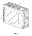
- FIG. 2 aillustrates a perspective view of a camera for use with the camera system, according to one embodiment.
- FIG. 2 billustrates a perspective view of a rear of a camera for use with the camera system, according to one embodiment.
- FIG. 3illustrates an exploded view of a swivel camera mount with a first locking mechanism, according to one embodiment.
- FIGS. 4 a , 4 b , and 4 cillustrate a swivel camera mount with a first locking mechanism, according to one embodiment.
- FIG. 5illustrates a swivel camera mount with a second locking mechanism, according to one embodiment.
- FIG. 6illustrates an exploded view of the swivel camera mount of FIG. 5 , according to one embodiment.
- a camera systemincludes a camera and a camera housing structured to at least partially enclose the camera.
- the cameracomprises a camera body having a camera lens structured on a front surface of the camera body, various indicators on the front of the surface of the camera body (such as LEDs, displays, and the like), various input mechanisms (such as buttons, switches, and touch-screen mechanisms), and electronics (e.g., imaging electronics, power electronics, etc.) internal to the camera body for capturing images via the camera lens and/or performing other functions.
- the camera housingincludes a lens window structured on the front surface of the camera housing and configured to substantially align with the camera lens, and one or more indicator windows structured on the front surface of the camera housing and configured to substantially align with the camera indicators.
- FIGS. 1 a and 1 billustrate various views of a camera system according to one example embodiment.
- the camera systemincludes, among other components, a camera housing 100 .
- a first housing portion 101includes a front face with four sides (i.e., a top side, bottom side, left side, and right side) structured to form a cavity that receives a camera (e.g. a still camera or video camera), and a second housing portion 102 structured to couple to the first housing portion 101 and securely enclose a camera within the camera housing 100 .
- the first housing portion 101 and second housing portion 102can be pivotally coupled via a hinge mechanism (described in greater detail in FIG. 1 b ), and can securely couple via a latch mechanism 103 .
- the camera housing 100may not include one or more sides or faces.
- the camera housing 100may not include a front or back face, allowing the front face and rear face of the camera to be exposed when partially enclosed by the top side, bottom side, left side, and right side of the camera housing 100 .
- the camera housing 100has a small form factor (e.g., a height of approximately 4 to 6 centimeters, a width of approximately 5 to 7 centimeters, and a depth of approximately 1 to 4 centimeters), and is lightweight (e.g., approximately 50 to 150 grams).
- the camera housing 100can be rigid (or substantially rigid) (e.g., plastic, metal, fiberglass, etc.) or pliable (or substantially pliable) (e.g., leather, vinyl, neoprene, etc.).
- the camera housing 100may be appropriately configured for use in various elements.
- the camera housing 100may comprise a waterproof enclosure that protects a camera from water when used, for example, while surfing or scuba diving.
- Portions of the camera housing 100may include exposed areas to allow a user to manipulate buttons on the camera that are associated with the camera functionality. Alternatively, such areas may be covered with a pliable material to allow the user to manipulate the buttons through the camera housing 100 .
- the top face of the camera housing 100includes an outer shutter button 112 structured so that a shutter button of the camera is substantially aligned with the outer shutter button 112 when the camera is secured within the camera housing 100 .
- the shutter button 112 of the camerais operationally coupled to the outer shutter button 112 so that pressing the outer shutter button 112 allows the user to operate the camera shutter button.
- the front face of the camera housing 100includes a lens window 104 structured so that a lens of the camera is substantially aligned with the lens windows 104 when the camera is secured within the camera housing 100 .
- the lens window 104can be adapted for use with a conventional lens, a wide angle lens, a flat lens, or any other specialized camera lens.
- the camera housing 100includes one or more securing structures 120 for securing the camera housing 100 to one of a variety of mounting devices such as a clip-style mount.
- the camera housing 100includes a plurality of protrusions 124 , each including a hole 126 configured to receive a coupling mechanism, for instance, a turnable handscrew to pivotally couple the camera housing 100 to a mounting device including a plurality of reciprocal protrusions.
- the camera housing 100can be secured to a different type of mounting structure, and can be secured to a mounting structure via a different type of coupling mechanism.
- the camera housing 100includes an indicator window 106 structured so that one or more camera indicators are substantially aligned with the indicator window 106 when the camera is secured within the camera housing 100 .
- the indicator window 106can be any shape or size, and can be made of the same material as the remainder of the camera housing 100 , or can be made of any other material, for instance a transparent or translucent material and/or a non-reflective material.
- the described housing 100may also be adapted for a wider range of devices of varying shapes, sizes and dimensions besides cameras.
- an expansion modulemay be attached to housing 100 to add expanded features to electronic devices such as cell phones, music players, personal digital assistants (“PDAs”), global positioning system (“GPS”) units, or other portable electronic devices.
- PDAspersonal digital assistants
- GPSglobal positioning system
- FIG. 1 bis a rear perspective view of camera housing 100 , according to one example embodiment.
- the second housing portion 102detachably couples with the first housing portion 101 opposite the front face of the first housing portion 101 .
- the first housing portion 101 and second housing portion 102are collectively structured to enclose a camera within the cavity formed when the second housing portion 102 is securely coupled to the first housing portion 101 in a closed position.
- the second housing portion 102pivots around a hinge mechanism 130 , allowing the second housing portion 102 to be either in a closed position relative to the first housing portion 101 (for instance, when the second housing portion 102 is securely coupled to the first housing portion 101 via the latch mechanism 103 ), or in an open position (when the first housing portion 101 and the second housing portion 102 are not coupled via the latch mechanism 103 ).
- a cameracan be removed from or placed into the camera housing 100 , and in the closed position, the camera can be securely enclosed within the camera housing 100 .
- the latch mechanism 103includes a hook-shaped lateral bar configured to securely couple around a reciprocal structure of the second housing portion 102 .
- the latch mechanism 103includes different fastening structures for securing the second housing portion 102 to the first housing portion 101 , for example a button assembly, a buckle assembly, a clip assembly, a hook and loop assembly, a magnet assembly, a ball and catch assembly, and an adhesive assembly, or any other type of securing mechanism.
- the hinge 130is instead located on the top face of the housing 100
- the latch mechanism 103is located on the bottom face of the housing 100
- the hinge 130 and the latch mechanism 103may be located on opposite side faces of the camera housing 100 .
- the housing 100includes a watertight seal so that the housing 100 is waterproof when the second housing portion 102 is in the closed position.
- the second housing portion 102includes a sealing structure positioned on interior edges of the second housing portion 102 . The sealing structure provides a watertight seal between the first housing portion 101 and the second housing portion when the latch mechanism securely couples the housing portions.
- FIG. 2 aillustrates a camera 200 for use with the camera systems described herein, according to one example embodiment.
- the camera 200is configured to capture images and video, and to store captured images and video for subsequent display or playback.
- the camera 200is adapted to fit within camera housing, such as the housing 100 discussed above or any other housing described herein.
- the camera 200includes a lens 202 configured to receive light incident upon the lens and to direct received light onto an image sensor internal to the lens for capture by the image sensor.
- the lens 202is enclosed by a lens ring 204 .
- the camera 200can include various indicators, including the LED lights 206 and the LED display 208 shown in FIG. 2 a .
- the LED lights and the LED display 208are configured to substantially align with the indicator window 106 and be visible through the housing 100 .
- the camera 200can also include buttons 210 configured to allow a user of the camera to interact with the camera, to turn the camera on, to initiate the capture of video or images, and to otherwise configure the operating mode of the camera.
- the camera 200can also include one or more microphones 212 configured to receive and record audio signals in conjunction with recording video.
- the side of the camera 200includes an I/O interface 214 . Though the embodiment of FIG. 2 a illustrates the I/O interface 214 enclosed by a protective door, the I/O interface can include any type or number of I/O ports or mechanisms, such as USC ports, HDMI ports, memory card slots, and the like.
- FIG. 2 billustrates a perspective view of a rear of a camera 200 for use with the camera systems described herein, according to one embodiment.
- the camera 200includes a display 218 (such as an LCD or LED display) on the rear surface of the camera 200 .
- the display 218can be configured for use, for example, as an electronic view finder, to preview captured images or videos, or to perform any other suitable function.
- the camera 200also includes an expansion pack interface 220 configured to receive a removable expansion pack, such as an extra battery module, a wireless module, and the like. Removable expansion packs, when coupled to the camera 200 , provide additional functionality to the camera via the expansion pack interface 220 .
- FIG. 3illustrates an exploded view of a swivel mount component 300 with a first locking mechanism, according to one embodiment.
- the swivel mount component 300includes an inner rotating component 310 , and an outer sleeve component 320 .
- the inner rotating component 310is configured to be at least partially enclosed and within the outer sleeve component 320 .
- the inner rotating component 310can couple to a camera housing (such as the camera housing 100 of FIGS. 1 a and 1 b ), which in turn can securely enclose a camera (such as the camera 200 of FIGS. 2 a and 2 b ), thereby coupling the camera to the inner rotating component 310 .
- the inner rotating component 310can rotate in a horizontal plane defined by a top surface 322 of the outer sleeve component 320 , and can allow a camera housing coupled to the inner rotating component 310 to pivot up to 90 degrees or more within one or more vertical planes relative to the inner rotating component 310 .
- the outer sleeve component 320can be configured to securely couple to a base mount component (not illustrated), and can pivot up to 90 degrees or more within one or more vertical planes relative to the base mount component.
- the base mount componentmay in turn be coupled to an object such as sports equipment, a vehicle, a surface, or a user thereby coupling a camera coupled to the inner rotating component 310 (which in turn is coupled to the outer sleeve component 320 coupled to the base mount component) to the object. This enables the rotation and pivoting of the camera relative to the object, allowing a user to configure the direction, angle, and orientation of the camera.
- the swivel mount component 300can be referred to as a “lower mount component” 300
- a housing securing a camera and configured to be coupled to the swivel mount component 300can be referred to herein as an “upper mount component.”
- the inner rotating component 310in various embodiments, can be fixedly or removably coupled within the outer sleeve component 320 , and can be rotated to face any direction in a 360 degree plane parallel to the horizontal plane defined by the top surface 322 of the outer sleeve component 320 .
- a cylindrical shaft 312 of the inner rotating component 310can be inserted and secured within a reciprocal cavity of the outer sleeve component 320 until a shaft lip 314 (which extends around an outer circumference of the cylindrical shaft) is aligned with and protrudes (at least in part) outward from a reciprocal opening 324 within the body of the outer sleeve component (in some embodiments, the reciprocal opening 324 extends up to 40% or more around the circumference of the outer sleeve component 320 ).
- the frictional force between an outer surface of the cylindrical shaft 312 and an inner surface of the reciprocal cavity of the outer sleeve component 320can be applied to secure or fix the orientation of the inner rotating component 310 relative to the outer sleeve component 320 .
- the frictional forcecan be reduced to allow for the rotation of the inner rotating component 310 to a new orientation relative to the outer sleeve component 320 , and can be re-applied in order to fix the inner rotating component 310 at the new orientation.
- FIGS. 4 a , 4 b , and 4 cillustrate the swivel camera mount with a first locking mechanism, according to one embodiment.
- the inner rotating component 310includes a set of evenly spaced protrusions 405 that extend vertically from a protrusion buttress 420 .
- Each protrusion 405includes a hole 410 (e.g., a pin hole), such that a pin, screw, or other securing device (“pin” hereinafter) may be inserted through each hole 410 unimpeded.
- the pinis a turntable handscrew, while in other embodiments the pin is a threaded screw, a rod, a clip, or other similar device.
- a first outer protrusion 405includes a raised nut cap guide 415 through which a nut cap is inserted, allowing the pin to be screwed into the nut cap, securing the pin within the holes 410 .
- a reciprocal set of protrusions of an upper mount component(such as the protrusions 120 of FIGS. 1 a and 1 b ) with a reciprocal set of holes can interlock with the set of protrusions 405 such that the holes 405 and the reciprocal holes align, allowing a pin to pass through the aligned holes, securing the upper mount component to the swivel mount component 300 .
- the pinIn a loosened configuration, the pin enables an upper mount component to rotate around the pin relative to the swivel mount component 300 . In a tightened configuration, the pin secures the upper mount component at a fixed angle relative to the swivel mount component 300 .
- the outer sleeve component 320includes an additional set of evenly spaced protrusions 450 that extend vertically from the bottom surface of reciprocal cavity.
- Each protrusion 450includes a hole 460 (e.g., a pin hole), such that a pin, screw, or other securing device (“pin” hereafter) may be inserted through each hole 460 unimpeded.
- the fastening pinis a turntable handscrew, while in other embodiments the pin is a threaded screw, a rod, a clip, or other similar device.
- a reciprocal set of protrusions of a base mount component (not illustrated) with a reciprocal set of holescan interlock with the set of protrusions 450 such that the holes 460 and the reciprocal holes align, allowing a pin to pass through the aligned holes, securing the swivel mount component 300 to the base mount component.
- the pinIn a loosened configuration, the pin enables the swivel mount component 300 to rotate around the pin relative to the base mount component 300 .
- the pinsecures the swivel mount component at a fixed angle relative to the base mount component.
- Flexion tracks 455located on the outer surface of the protrusions 450 provide guides for the swivel mount component 300 to pivot around the pin.
- the cylindrical shaft 312extends from the protrusion buttress 420 .
- the buttress 420 and the shaft lip 314are flattened continuous components made of the same material (e.g. polymer plastic) as the cylindrical shaft 312 .
- the components of the inner rotating component 310are molded as a single component.
- the diameter of the cylindrical shaft 312is substantially less than the diameter of the protrusion buttress 420 and the shaft lip 314 , allowing the inner rotating component 310 to be inserted into a reciprocal cavity of the outer sleeve component 320 .
- the protrusion buttress 420abuts a top surface 322 of the outer sleeve component 310 .
- the shaft lip 314protruding from the reciprocal opening 324 , abuts a surface of the reciprocal opening 324 and prevents longitudinal separation of the inner rotating component 310 from the outer sleeve component 320 .
- the cylindrical shaft 425allows the inner rotating component 310 (and thus a camera coupled to the inner rotating component 310 ) to swivel relative to the outer sleeve component 320 .
- the outer sleeve component 320includes two protrusions 440 on either side of a separation 430 , protruding outward from the outer sleeve component 320 .
- Each protrusion 440includes a clamp pin hole 445 .
- the protrusions 440forcibly compress towards each other, thereby reducing the width of the separation 430 and (accordingly) the circumference of the inside surface of the reciprocal cavity of the outer sleeve component 320 , enacting a friction force on the cylindrical shaft 312 and securing the inner rotating component 310 into a fixed position relative to the outer sleeve component 320 .
- the clamp pinWhen the clamp pin is loosened, the width of the separation 430 is increased, thereby increasing the circumference of the inside surface of the reciprocal cavity of the outer sleeve component 320 , allowing the inner rotating component 310 to rotate in a horizontal plane relative to the outer sleeve component 320 .
- the clamp pinis a turntable handscrew, while in other embodiments the clamp pin is a threaded screw, a rod, a clip, or other suitable device.
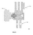
- FIGS. 5 and 6illustrate a second locking mechanism for the swivel camera mount described herein, according to one embodiment.
- the swivel mount component 500includes an inner rotating component 510 and an outer sleeve component 520 .
- the inner rotating component 510 and the outer sleeve component 520are the inner rotating component 310 and the outer sleeve component 320 as described above.
- a locking screw 530is illustrated in a locked configuration, inserted perpendicularly into a reciprocal screw hole in an outer surface of the outer sleeve component 520 aligned with a tapered groove shaft within the inner rotating component 510 .
- the locking screw 530securely abuts the tapered groove shaft within the inner rotating component, fixedly securing the inner rotating component 510 relative to the outer sleeve component 520 .
- the locking screwcan be loosened into a loosened configuration, allowing the inner rotating component 510 to rotate in a horizontal plane relative to the outer sleeve component 520 .
- FIG. 6illustrates a tapered groove shaft 605 within the inner rotating component 510 , a threaded aperture 610 within an outer surface of the outer sleeve component 520 , and a locking screw 530 which includes a screw handle 620 and a screw thread 615 .
- the tapered groove shaft 605which includes a “V”-shaped indentation around the circumference of the inner rotating component 510 , is aligned with the threaded aperture 610 .
- the screw thread 615can be tightened such that the screw thread 615 forcibly abuts the “V”-shaped indentation of the tapered groove shaft 605 , creating friction between the screw thread 615 and the tapered groove shaft 605 and fixedly securing the inner rotating component 510 relative to the outer sleeve component 520 .
- the screw thread 615includes a “V”-shaped end 618 configured to align with the “V”-shaped indentation of the tapered groove shaft 605 when the screw 530 is configured into the locked configuration.
- the swivel mount component 500includes a threaded locking component.
- a locking mechanisme.g. locking pin, locking screw
- the protrusions 440forcibly compress towards each other, thereby reducing the width of the separation 430 and (accordingly) the circumference of the inside surface of the reciprocal cavity of the outer sleeve component 320 .
- the swivel mount component 500can include a horizontal groove within the cylindrical shaft 312 through which the locking mechanism at least partially passes when inserted into the pin holes 445 .
- the locking mechanismprevents the removal of the inner rotating component 310 from the outer sleeve component 320 .
- the locking mechanismmay be made of metal, a plastic polymer, or the like.
- the fastening portion of the locking mechanismcan be a thumb screw, a hexagonal screw, or any suitable fastening device.
- Coupledalong with its derivatives.
- the term “coupled” as used hereinis not necessarily limited to two or more elements being in direct physical or electrical contact. Rather, the term “coupled” may also encompass two or more elements are not in direct contact with each other, but yet still co-operate or interact with each other, or are structured to provide a thermal conduction path between the elements.
- the terms “comprises,” “comprising,” “includes,” “including,” “has,” “having” or any other variation thereof,are intended to cover a non-exclusive inclusion.
- a process, method, article, or apparatus that comprises a list of elementsis not necessarily limited to only those elements but may include other elements not expressly listed or inherent to such process, method, article, or apparatus.
- any reference to “one embodiment” or “an embodiment”means that a particular element, feature, structure, or characteristic described in connection with the embodiment is included in at least one embodiment.
- the appearances of the phrase “in one embodiment” in various places in the specificationare not necessarily all referring to the same embodiment.
Landscapes
- Engineering & Computer Science (AREA)
- General Engineering & Computer Science (AREA)
- Mechanical Engineering (AREA)
- Physics & Mathematics (AREA)
- General Physics & Mathematics (AREA)
- Multimedia (AREA)
- Signal Processing (AREA)
- Accessories Of Cameras (AREA)
Abstract
Description
Claims (26)
Priority Applications (2)
| Application Number | Priority Date | Filing Date | Title |
|---|---|---|---|
| US14/604,518US9360742B1 (en) | 2015-01-23 | 2015-01-23 | Swivel camera mount |
| US15/150,417US9625791B2 (en) | 2015-01-23 | 2016-05-09 | Swivel camera mount |
Applications Claiming Priority (1)
| Application Number | Priority Date | Filing Date | Title |
|---|---|---|---|
| US14/604,518US9360742B1 (en) | 2015-01-23 | 2015-01-23 | Swivel camera mount |
Related Child Applications (1)
| Application Number | Title | Priority Date | Filing Date |
|---|---|---|---|
| US15/150,417ContinuationUS9625791B2 (en) | 2015-01-23 | 2016-05-09 | Swivel camera mount |
Publications (1)
| Publication Number | Publication Date |
|---|---|
| US9360742B1true US9360742B1 (en) | 2016-06-07 |
Family
ID=56083082
Family Applications (2)
| Application Number | Title | Priority Date | Filing Date |
|---|---|---|---|
| US14/604,518Expired - Fee RelatedUS9360742B1 (en) | 2015-01-23 | 2015-01-23 | Swivel camera mount |
| US15/150,417Expired - Fee RelatedUS9625791B2 (en) | 2015-01-23 | 2016-05-09 | Swivel camera mount |
Family Applications After (1)
| Application Number | Title | Priority Date | Filing Date |
|---|---|---|---|
| US15/150,417Expired - Fee RelatedUS9625791B2 (en) | 2015-01-23 | 2016-05-09 | Swivel camera mount |
Country Status (1)
| Country | Link |
|---|---|
| US (2) | US9360742B1 (en) |
Cited By (49)
| Publication number | Priority date | Publication date | Assignee | Title |
|---|---|---|---|---|
| US20160252801A1 (en)* | 2015-01-23 | 2016-09-01 | Gopro, Inc. | Swivel Camera Mount |
| CN106287134A (en)* | 2016-10-13 | 2017-01-04 | 广东弘景光电科技股份有限公司 | It is applied to the double support taking the photograph in module of panorama |
| US9588407B1 (en)* | 2016-04-06 | 2017-03-07 | Gopro, Inc. | Invertible timer mount for camera |
| USD785069S1 (en)* | 2015-09-01 | 2017-04-25 | Avant Technology, Inc. | Camera housing |
| CN106594468A (en)* | 2016-12-30 | 2017-04-26 | 浙江吉利汽车研究院有限公司 | Camera fixing rack and camera fixing device |
| USD810175S1 (en)* | 2016-05-02 | 2018-02-13 | Hanwha Techwin Co., Ltd. | Camera |
| USD827697S1 (en)* | 2016-08-09 | 2018-09-04 | Gopro, Inc. | Camera housing |
| USD827696S1 (en)* | 2016-08-09 | 2018-09-04 | Gopro, Inc. | Camera housing |
| US10101637B2 (en) | 2015-09-11 | 2018-10-16 | Avant Technology, Inc. | Camera case with removable carrier, filter receiver, external battery and supplemental memory storage |
| US10122904B2 (en) | 2016-07-11 | 2018-11-06 | Gopro, Inc. | Drain mechanism for camera controller |
| USD833505S1 (en)* | 2016-09-13 | 2018-11-13 | Shenzhen Baker Av Digital Technology Co., Ltd. | Sports camera |
| USD890835S1 (en) | 2017-12-28 | 2020-07-21 | Gopro, Inc. | Camera |
| USD894256S1 (en) | 2018-08-31 | 2020-08-25 | Gopro, Inc. | Camera mount |
| USD903740S1 (en) | 2018-09-14 | 2020-12-01 | Gopro, Inc. | Camera |
| USD905786S1 (en) | 2018-08-31 | 2020-12-22 | Gopro, Inc. | Camera mount |
| USD907680S1 (en) | 2018-08-31 | 2021-01-12 | Gopro, Inc. | Camera |
| USD911411S1 (en) | 2019-09-13 | 2021-02-23 | Gopro, Inc. | Camera housing |
| US10928711B2 (en) | 2018-08-07 | 2021-02-23 | Gopro, Inc. | Camera and camera mount |
| USD921084S1 (en) | 2019-09-13 | 2021-06-01 | Gopro, Inc. | Camera housing |
| USD921740S1 (en) | 2019-06-11 | 2021-06-08 | Gopro, Inc. | Camera |
| USD928863S1 (en) | 2019-09-17 | 2021-08-24 | Gopro, Inc. | Camera light |
| USD946074S1 (en) | 2020-08-14 | 2022-03-15 | Gopro, Inc. | Camera |
| USD946072S1 (en) | 2020-08-10 | 2022-03-15 | Gopro, Inc. | Camera housing |
| USD946071S1 (en) | 2020-06-30 | 2022-03-15 | Gopro, Inc. | Camera housing |
| USD950629S1 (en) | 2019-09-17 | 2022-05-03 | Gopro, Inc. | Camera |
| USD953404S1 (en) | 2020-08-14 | 2022-05-31 | Gopro, Inc. | Camera housing |
| USD953406S1 (en) | 2019-09-30 | 2022-05-31 | Gopro, Inc. | Camera housing |
| USD954132S1 (en) | 2020-07-31 | 2022-06-07 | Gopro, Inc. | Camera housing |
| USD963025S1 (en)* | 2020-11-05 | 2022-09-06 | Hu Ruan | Backpack clip mount for camera |
| US11675251B2 (en) | 2019-09-18 | 2023-06-13 | Gopro, Inc. | Door assemblies for image capture devices |
| US11782327B2 (en) | 2020-07-02 | 2023-10-10 | Gopro, Inc. | Removable battery door assemblies for image capture devices |
| USD1014603S1 (en) | 2019-09-13 | 2024-02-13 | Gopro, Inc. | Camera housing |
| USD1029746S1 (en) | 2020-07-31 | 2024-06-04 | Gopro, Inc. | Battery |
| USD1029745S1 (en) | 2019-09-13 | 2024-06-04 | Gopro, Inc. | Camera battery |
| USD1031810S1 (en)* | 2022-04-05 | 2024-06-18 | Gopro, Inc. | Camera mount |
| USD1038209S1 (en) | 2015-12-15 | 2024-08-06 | Gopro, Inc. | Camera |
| US12066748B2 (en) | 2019-09-18 | 2024-08-20 | Gopro, Inc. | Door assemblies for image capture devices |
| USD1050227S1 (en) | 2020-08-14 | 2024-11-05 | Gopro, Inc. | Camera door |
| US12189276B2 (en) | 2021-11-15 | 2025-01-07 | Gopro, Inc. | Multi-support accessory with integrated power supply for image capture devices |
| USD1061682S1 (en) | 2022-08-04 | 2025-02-11 | Gopro, Inc. | Camera door |
| USD1063818S1 (en) | 2017-09-28 | 2025-02-25 | Gopro, Inc. | Battery |
| US12245671B2 (en) | 2019-09-30 | 2025-03-11 | Gopro, Inc. | Camera case |
| USD1066462S1 (en) | 2021-02-12 | 2025-03-11 | Gopro, Inc. | Camera door |
| US12262104B2 (en) | 2019-09-13 | 2025-03-25 | Gopro, Inc. | Image capture device |
| US12321084B2 (en) | 2022-08-12 | 2025-06-03 | Gopro, Inc. | Interconnect mechanism for image capture device |
| USD1085204S1 (en)* | 2023-08-10 | 2025-07-22 | Gopro, Inc. | Camera mount adapter |
| US12379650B2 (en) | 2023-02-15 | 2025-08-05 | Gopro, Inc. | Reinforced image capture devices including interconnect mechanisms with a threaded accessory interface |
| USD1092591S1 (en) | 2024-05-22 | 2025-09-09 | Gopro, Inc. | Camera housing |
| USD1096914S1 (en) | 2024-03-15 | 2025-10-07 | Gopro, Inc. | Camera mount |
Families Citing this family (21)
| Publication number | Priority date | Publication date | Assignee | Title |
|---|---|---|---|---|
| USD710921S1 (en)* | 2013-07-18 | 2014-08-12 | Gopro, Inc. | Camera housing |
| USD776741S1 (en) | 2015-12-29 | 2017-01-17 | Gopro, Inc. | Camera dive housing |
| US11215426B1 (en)* | 2018-05-11 | 2022-01-04 | Robert Marshall Campbell | Sight adjustable display mount for firearms |
| USD835910S1 (en)* | 2016-01-19 | 2018-12-18 | Nexark, Inc. | Waterproof case |
| CA2985211C (en)* | 2016-09-30 | 2019-09-24 | Anji Jintai Fastener Co., Ltd. | Foldable five-star foot |
| USD861766S1 (en) | 2017-01-13 | 2019-10-01 | Gopro, Inc. | Camera lens filter |
| EP3673474B1 (en) | 2017-09-27 | 2023-05-17 | Zhejiang Dahua Technology Co., Ltd. | A surveillance device |
| USD856391S1 (en)* | 2017-10-23 | 2019-08-13 | Shenzhen SaiNa Electronic Technology Co., Ltd | Camera housing |
| CN109059803A (en)* | 2018-08-14 | 2018-12-21 | 贵州大学 | A kind of ore mining three-dimensional laser scanner |
| USD918988S1 (en) | 2019-09-13 | 2021-05-11 | Gopro, Inc. | Camera lens cover |
| USD918989S1 (en) | 2019-09-17 | 2021-05-11 | Gopro, Inc. | Camera lens cover |
| US10753530B2 (en)* | 2019-01-30 | 2020-08-25 | Ful Chee Ent Co., Ltd. | Quick-release mounting structure of action camera casing |
| USD949222S1 (en) | 2019-09-17 | 2022-04-19 | Gopro, Inc. | Camera housing |
| USD942875S1 (en)* | 2020-03-12 | 2022-02-08 | Aukey Technology Co., Ltd | Laser level |
| USD947920S1 (en) | 2020-06-30 | 2022-04-05 | Gopro, Inc. | Camera housing |
| CN112066226A (en)* | 2020-09-14 | 2020-12-11 | 南京世博电控技术有限公司 | Unmanned vehicle remote monitoring system and monitoring method |
| LU102249B1 (en) | 2020-11-26 | 2022-05-30 | Bega Gantenbrink Leuchten Kg | Adapter system for the detachable connection of a lamp with an accessory |
| US11448944B2 (en) | 2021-01-09 | 2022-09-20 | Christian A. Goeller | Moldable and flexible mount for a curved surface |
| USD1010427S1 (en) | 2021-01-09 | 2024-01-09 | Christian A. Goeller | Mounting bracket |
| US12126152B2 (en) | 2021-04-29 | 2024-10-22 | APG Vision LLC | Ball mount with integrated cable gland |
| US20230365288A1 (en)* | 2022-05-16 | 2023-11-16 | Moshe Chaim Ephraim Block | Hard shell saddle bags |
Citations (5)
| Publication number | Priority date | Publication date | Assignee | Title |
|---|---|---|---|---|
| US20050265711A1 (en)* | 2004-05-27 | 2005-12-01 | Heibel Thomas S | Camera Mount |
| US20080107414A1 (en)* | 2006-11-07 | 2008-05-08 | Joseph Showalter | Image capture device mounting assembly for firearm |
| US8970689B2 (en)* | 2011-11-02 | 2015-03-03 | Gopro, Inc. | Camera mounting assembly |
| US9033596B2 (en)* | 2012-10-15 | 2015-05-19 | Gopro, Inc. | Camera mount vibration dampener |
| US9229299B1 (en)* | 2014-04-09 | 2016-01-05 | Swivit, Inc. | Multi-directional rotational mount |
Family Cites Families (4)
| Publication number | Priority date | Publication date | Assignee | Title |
|---|---|---|---|---|
| US8793917B2 (en)* | 2011-03-25 | 2014-08-05 | Robert Wayne Russell | Camera mount apparatus and system for a scope |
| US9699365B2 (en)* | 2012-10-04 | 2017-07-04 | Jigabot, LLC. | Compact, rugged, intelligent tracking apparatus and method |
| US9360742B1 (en)* | 2015-01-23 | 2016-06-07 | Gopro, Inc. | Swivel camera mount |
| US10044932B2 (en)* | 2015-03-13 | 2018-08-07 | Sensormatic Electronics, LLC | Wide angle fisheye security camera having offset lens and image sensor |
- 2015
- 2015-01-23USUS14/604,518patent/US9360742B1/ennot_activeExpired - Fee Related
- 2016
- 2016-05-09USUS15/150,417patent/US9625791B2/ennot_activeExpired - Fee Related
Patent Citations (5)
| Publication number | Priority date | Publication date | Assignee | Title |
|---|---|---|---|---|
| US20050265711A1 (en)* | 2004-05-27 | 2005-12-01 | Heibel Thomas S | Camera Mount |
| US20080107414A1 (en)* | 2006-11-07 | 2008-05-08 | Joseph Showalter | Image capture device mounting assembly for firearm |
| US8970689B2 (en)* | 2011-11-02 | 2015-03-03 | Gopro, Inc. | Camera mounting assembly |
| US9033596B2 (en)* | 2012-10-15 | 2015-05-19 | Gopro, Inc. | Camera mount vibration dampener |
| US9229299B1 (en)* | 2014-04-09 | 2016-01-05 | Swivit, Inc. | Multi-directional rotational mount |
Cited By (100)
| Publication number | Priority date | Publication date | Assignee | Title |
|---|---|---|---|---|
| US20160252801A1 (en)* | 2015-01-23 | 2016-09-01 | Gopro, Inc. | Swivel Camera Mount |
| US9625791B2 (en)* | 2015-01-23 | 2017-04-18 | Gopro, Inc. | Swivel camera mount |
| USD785069S1 (en)* | 2015-09-01 | 2017-04-25 | Avant Technology, Inc. | Camera housing |
| US10101637B2 (en) | 2015-09-11 | 2018-10-16 | Avant Technology, Inc. | Camera case with removable carrier, filter receiver, external battery and supplemental memory storage |
| USD1038209S1 (en) | 2015-12-15 | 2024-08-06 | Gopro, Inc. | Camera |
| USD1077027S1 (en) | 2015-12-15 | 2025-05-27 | Gopro, Inc. | Camera |
| US9588407B1 (en)* | 2016-04-06 | 2017-03-07 | Gopro, Inc. | Invertible timer mount for camera |
| USD810175S1 (en)* | 2016-05-02 | 2018-02-13 | Hanwha Techwin Co., Ltd. | Camera |
| US10848659B2 (en) | 2016-07-11 | 2020-11-24 | Gopro, Inc. | Drain mechanism for camera controller |
| US10122904B2 (en) | 2016-07-11 | 2018-11-06 | Gopro, Inc. | Drain mechanism for camera controller |
| USD827697S1 (en)* | 2016-08-09 | 2018-09-04 | Gopro, Inc. | Camera housing |
| USD827696S1 (en)* | 2016-08-09 | 2018-09-04 | Gopro, Inc. | Camera housing |
| USD833505S1 (en)* | 2016-09-13 | 2018-11-13 | Shenzhen Baker Av Digital Technology Co., Ltd. | Sports camera |
| CN106287134A (en)* | 2016-10-13 | 2017-01-04 | 广东弘景光电科技股份有限公司 | It is applied to the double support taking the photograph in module of panorama |
| CN106594468B (en)* | 2016-12-30 | 2018-10-02 | 浙江吉利汽车研究院有限公司 | Camera fixing frame and camera fixing device |
| CN106594468A (en)* | 2016-12-30 | 2017-04-26 | 浙江吉利汽车研究院有限公司 | Camera fixing rack and camera fixing device |
| USD1063818S1 (en) | 2017-09-28 | 2025-02-25 | Gopro, Inc. | Battery |
| USD890835S1 (en) | 2017-12-28 | 2020-07-21 | Gopro, Inc. | Camera |
| USD1079788S1 (en) | 2017-12-28 | 2025-06-17 | Gopro, Inc. | Camera |
| USD1036536S1 (en) | 2017-12-28 | 2024-07-23 | Gopro, Inc. | Camera |
| USD998017S1 (en) | 2017-12-28 | 2023-09-05 | Gopro, Inc. | Camera |
| US12399419B2 (en) | 2018-08-07 | 2025-08-26 | Gopro, Inc. | Camera and camera mount |
| US11662651B2 (en) | 2018-08-07 | 2023-05-30 | Gopro, Inc. | Camera and camera mount |
| US10928711B2 (en) | 2018-08-07 | 2021-02-23 | Gopro, Inc. | Camera and camera mount |
| USD989165S1 (en) | 2018-08-31 | 2023-06-13 | Gopro, Inc. | Camera mount |
| USD907680S1 (en) | 2018-08-31 | 2021-01-12 | Gopro, Inc. | Camera |
| USD894256S1 (en) | 2018-08-31 | 2020-08-25 | Gopro, Inc. | Camera mount |
| USD1023115S1 (en) | 2018-08-31 | 2024-04-16 | Gopro, Inc. | Camera mount |
| USD990540S1 (en) | 2018-08-31 | 2023-06-27 | Gopro, Inc. | Camera |
| USD1058641S1 (en) | 2018-08-31 | 2025-01-21 | Gopro, Inc. | Camera |
| USD905786S1 (en) | 2018-08-31 | 2020-12-22 | Gopro, Inc. | Camera mount |
| USD903740S1 (en) | 2018-09-14 | 2020-12-01 | Gopro, Inc. | Camera |
| USD950628S1 (en) | 2018-09-14 | 2022-05-03 | Gopro, Inc. | Camera |
| USD963020S1 (en) | 2018-09-14 | 2022-09-06 | Gopro, Inc. | Camera |
| USD1009124S1 (en) | 2019-06-11 | 2023-12-26 | Gopro, Inc. | Camera |
| USD995600S1 (en) | 2019-06-11 | 2023-08-15 | Gopro, Inc. | Camera |
| USD954128S1 (en) | 2019-06-11 | 2022-06-07 | Gopro, Inc. | Camera |
| USD941904S1 (en) | 2019-06-11 | 2022-01-25 | Gopro, Inc. | Camera |
| USD921740S1 (en) | 2019-06-11 | 2021-06-08 | Gopro, Inc. | Camera |
| USD921084S1 (en) | 2019-09-13 | 2021-06-01 | Gopro, Inc. | Camera housing |
| USD978953S1 (en) | 2019-09-13 | 2023-02-21 | Gopro, Inc. | Camera housing |
| US12262104B2 (en) | 2019-09-13 | 2025-03-25 | Gopro, Inc. | Image capture device |
| USD1033520S1 (en) | 2019-09-13 | 2024-07-02 | Gopro, Inc. | Camera housing |
| USD1029745S1 (en) | 2019-09-13 | 2024-06-04 | Gopro, Inc. | Camera battery |
| USD957503S1 (en) | 2019-09-13 | 2022-07-12 | Gopro, Inc. | Camera housing |
| USD1014603S1 (en) | 2019-09-13 | 2024-02-13 | Gopro, Inc. | Camera housing |
| USD1014604S1 (en) | 2019-09-13 | 2024-02-13 | Gopro, Inc. | Camera housing |
| USD1019740S1 (en) | 2019-09-13 | 2024-03-26 | Gopro, Inc. | Camera housing |
| USD911411S1 (en) | 2019-09-13 | 2021-02-23 | Gopro, Inc. | Camera housing |
| USD929489S1 (en) | 2019-09-13 | 2021-08-31 | Gopro, Inc. | Camera housing |
| USD988390S1 (en) | 2019-09-17 | 2023-06-06 | Gopro, Inc. | Camera |
| USD928863S1 (en) | 2019-09-17 | 2021-08-24 | Gopro, Inc. | Camera light |
| USD956123S1 (en) | 2019-09-17 | 2022-06-28 | Gopro, Inc. | Camera |
| USD1024165S1 (en) | 2019-09-17 | 2024-04-23 | Gopro, Inc. | Camera |
| USD1054472S1 (en) | 2019-09-17 | 2024-12-17 | Gopro, Inc. | Camera light |
| USD1003979S1 (en) | 2019-09-17 | 2023-11-07 | Gopro, Inc. | Camera accessory mount |
| USD950629S1 (en) | 2019-09-17 | 2022-05-03 | Gopro, Inc. | Camera |
| USD997232S1 (en) | 2019-09-17 | 2023-08-29 | Gopro, Inc. | Camera |
| USD1090676S1 (en) | 2019-09-17 | 2025-08-26 | Gopro, Inc. | Camera |
| US12066749B2 (en) | 2019-09-18 | 2024-08-20 | Gopro, Inc. | Door assemblies for image capture devices |
| US11675251B2 (en) | 2019-09-18 | 2023-06-13 | Gopro, Inc. | Door assemblies for image capture devices |
| US12066748B2 (en) | 2019-09-18 | 2024-08-20 | Gopro, Inc. | Door assemblies for image capture devices |
| US12245671B2 (en) | 2019-09-30 | 2025-03-11 | Gopro, Inc. | Camera case |
| USD953406S1 (en) | 2019-09-30 | 2022-05-31 | Gopro, Inc. | Camera housing |
| USD946071S1 (en) | 2020-06-30 | 2022-03-15 | Gopro, Inc. | Camera housing |
| USD954125S1 (en) | 2020-06-30 | 2022-06-07 | Gopro, Inc. | Camera housing |
| USD963017S1 (en) | 2020-06-30 | 2022-09-06 | Gopro, Inc. | Camera housing |
| US11782327B2 (en) | 2020-07-02 | 2023-10-10 | Gopro, Inc. | Removable battery door assemblies for image capture devices |
| US12253793B2 (en) | 2020-07-02 | 2025-03-18 | Gopro, Inc. | Removable battery door assemblies for image capture devices |
| USD1029904S1 (en) | 2020-07-31 | 2024-06-04 | Gopro, Inc. | Camera housing |
| USD1029746S1 (en) | 2020-07-31 | 2024-06-04 | Gopro, Inc. | Battery |
| USD1013762S1 (en) | 2020-07-31 | 2024-02-06 | Gopro, Inc. | Camera housing |
| USD963023S1 (en) | 2020-07-31 | 2022-09-06 | Gopro, Inc. | Camera housing |
| USD954132S1 (en) | 2020-07-31 | 2022-06-07 | Gopro, Inc. | Camera housing |
| USD963016S1 (en) | 2020-07-31 | 2022-09-06 | Gopro, Inc. | Camera housing |
| USD954776S1 (en) | 2020-08-10 | 2022-06-14 | Gopro, Inc. | Camera housing |
| USD946072S1 (en) | 2020-08-10 | 2022-03-15 | Gopro, Inc. | Camera housing |
| USD977546S1 (en) | 2020-08-10 | 2023-02-07 | Gopro, Inc. | Camera housing |
| USD989841S1 (en) | 2020-08-14 | 2023-06-20 | Gopro, Inc. | Camera |
| USD950624S1 (en) | 2020-08-14 | 2022-05-03 | Gopro, Inc. | Camera |
| USD963726S1 (en) | 2020-08-14 | 2022-09-13 | Gopro, Inc. | Camera housing |
| USD946074S1 (en) | 2020-08-14 | 2022-03-15 | Gopro, Inc. | Camera |
| USD963022S1 (en) | 2020-08-14 | 2022-09-06 | Gopro, Inc. | Camera |
| USD1025173S1 (en) | 2020-08-14 | 2024-04-30 | Gopro, Inc. | Microphone cover of a camera housing |
| USD1004676S1 (en) | 2020-08-14 | 2023-11-14 | Gopro, Inc. | Camera |
| USD991318S1 (en) | 2020-08-14 | 2023-07-04 | Gopro, Inc. | Camera |
| USD953404S1 (en) | 2020-08-14 | 2022-05-31 | Gopro, Inc. | Camera housing |
| USD1050227S1 (en) | 2020-08-14 | 2024-11-05 | Gopro, Inc. | Camera door |
| USD963025S1 (en)* | 2020-11-05 | 2022-09-06 | Hu Ruan | Backpack clip mount for camera |
| USD1066462S1 (en) | 2021-02-12 | 2025-03-11 | Gopro, Inc. | Camera door |
| US12265317B2 (en)* | 2021-11-15 | 2025-04-01 | Gopro, Inc. | Multi-support accessory with integrated power supply for image capture devices |
| US12189276B2 (en) | 2021-11-15 | 2025-01-07 | Gopro, Inc. | Multi-support accessory with integrated power supply for image capture devices |
| USD1077016S1 (en) | 2022-04-05 | 2025-05-27 | Gopro, Inc. | Camera |
| USD1031810S1 (en)* | 2022-04-05 | 2024-06-18 | Gopro, Inc. | Camera mount |
| USD1061682S1 (en) | 2022-08-04 | 2025-02-11 | Gopro, Inc. | Camera door |
| US12321084B2 (en) | 2022-08-12 | 2025-06-03 | Gopro, Inc. | Interconnect mechanism for image capture device |
| US12379650B2 (en) | 2023-02-15 | 2025-08-05 | Gopro, Inc. | Reinforced image capture devices including interconnect mechanisms with a threaded accessory interface |
| USD1085204S1 (en)* | 2023-08-10 | 2025-07-22 | Gopro, Inc. | Camera mount adapter |
| USD1096914S1 (en) | 2024-03-15 | 2025-10-07 | Gopro, Inc. | Camera mount |
| USD1092591S1 (en) | 2024-05-22 | 2025-09-09 | Gopro, Inc. | Camera housing |
Also Published As
| Publication number | Publication date |
|---|---|
| US9625791B2 (en) | 2017-04-18 |
| US20160252801A1 (en) | 2016-09-01 |
Similar Documents
| Publication | Publication Date | Title |
|---|---|---|
| US9625791B2 (en) | Swivel camera mount | |
| US10547769B2 (en) | Swivel camera mount | |
| US10416538B2 (en) | Quick-release ball-and-socket joint camera mount | |
| US10025166B2 (en) | Swivel wrist mount | |
| US12222633B2 (en) | Camera housing | |
| US9513535B2 (en) | Camera mount for sports board | |
| US9369614B2 (en) | Camera mountable arm | |
| US9423673B2 (en) | Quick-release ball-and-socket joint camera mount | |
| US10539858B2 (en) | Camera mount | |
| US9383628B1 (en) | Humidity prevention system within a camera housing | |
| US9389487B2 (en) | Protective lens attachment |
Legal Events
| Date | Code | Title | Description |
|---|---|---|---|
| AS | Assignment | Owner name:GOPRO, INC., CALIFORNIA Free format text:ASSIGNMENT OF ASSIGNORS INTEREST;ASSIGNOR:HARRISON, RYAN;REEL/FRAME:035663/0492 Effective date:20150511 | |
| ZAAA | Notice of allowance and fees due | Free format text:ORIGINAL CODE: NOA | |
| ZAAB | Notice of allowance mailed | Free format text:ORIGINAL CODE: MN/=. | |
| AS | Assignment | Owner name:JPMORGAN CHASE BANK, N.A., AS ADMINISTRATIVE AGENT, ILLINOIS Free format text:SECURITY AGREEMENT;ASSIGNOR:GOPRO, INC.;REEL/FRAME:038184/0779 Effective date:20160325 Owner name:JPMORGAN CHASE BANK, N.A., AS ADMINISTRATIVE AGENT Free format text:SECURITY AGREEMENT;ASSIGNOR:GOPRO, INC.;REEL/FRAME:038184/0779 Effective date:20160325 | |
| STCF | Information on status: patent grant | Free format text:PATENTED CASE | |
| AS | Assignment | Owner name:JPMORGAN CHASE BANK, N.A., AS ADMINISTRATIVE AGENT, NEW YORK Free format text:SECURITY AGREEMENT;ASSIGNOR:GOPRO, INC.;REEL/FRAME:039851/0611 Effective date:20160826 Owner name:JPMORGAN CHASE BANK, N.A., AS ADMINISTRATIVE AGENT Free format text:SECURITY AGREEMENT;ASSIGNOR:GOPRO, INC.;REEL/FRAME:039851/0611 Effective date:20160826 | |
| MAFP | Maintenance fee payment | Free format text:PAYMENT OF MAINTENANCE FEE, 4TH YEAR, LARGE ENTITY (ORIGINAL EVENT CODE: M1551); ENTITY STATUS OF PATENT OWNER: LARGE ENTITY Year of fee payment:4 | |
| AS | Assignment | Owner name:GOPRO, INC., CALIFORNIA Free format text:RELEASE OF PATENT SECURITY INTEREST;ASSIGNOR:JPMORGAN CHASE BANK, N.A., AS ADMINISTRATIVE AGENT;REEL/FRAME:055106/0434 Effective date:20210122 | |
| FEPP | Fee payment procedure | Free format text:MAINTENANCE FEE REMINDER MAILED (ORIGINAL EVENT CODE: REM.); ENTITY STATUS OF PATENT OWNER: LARGE ENTITY | |
| LAPS | Lapse for failure to pay maintenance fees | Free format text:PATENT EXPIRED FOR FAILURE TO PAY MAINTENANCE FEES (ORIGINAL EVENT CODE: EXP.); ENTITY STATUS OF PATENT OWNER: LARGE ENTITY | |
| STCH | Information on status: patent discontinuation | Free format text:PATENT EXPIRED DUE TO NONPAYMENT OF MAINTENANCE FEES UNDER 37 CFR 1.362 | |
| FP | Lapsed due to failure to pay maintenance fee | Effective date:20240607 |