US9358388B2 - Systems and methods for detecting intrathecal penetration - Google Patents
Systems and methods for detecting intrathecal penetrationDownload PDFInfo
- Publication number
- US9358388B2 US9358388B2US14/326,301US201414326301AUS9358388B2US 9358388 B2US9358388 B2US 9358388B2US 201414326301 AUS201414326301 AUS 201414326301AUS 9358388 B2US9358388 B2US 9358388B2
- Authority
- US
- United States
- Prior art keywords
- patient
- impedance
- signal
- signal delivery
- delivery device
- Prior art date
- Legal status (The legal status is an assumption and is not a legal conclusion. Google has not performed a legal analysis and makes no representation as to the accuracy of the status listed.)
- Active
Links
- 230000035515penetrationEffects0.000titleclaimsabstractdescription29
- 238000007913intrathecal administrationMethods0.000titleclaimsabstractdescription27
- 238000000034methodMethods0.000titleabstractdescription79
- 241001269524DuraSpecies0.000claimsabstractdescription25
- 238000002560therapeutic procedureMethods0.000claimsdescription47
- 230000008569processEffects0.000description42
- 230000008054signal transmissionEffects0.000description42
- 210000000278spinal cordAnatomy0.000description29
- 238000001514detection methodMethods0.000description16
- 210000001519tissueAnatomy0.000description13
- 238000003780insertionMethods0.000description12
- 230000037431insertionEffects0.000description12
- 238000005516engineering processMethods0.000description11
- 230000008901benefitEffects0.000description10
- 210000001175cerebrospinal fluidAnatomy0.000description10
- 238000002513implantationMethods0.000description10
- 239000000463materialSubstances0.000description10
- 238000002594fluoroscopyMethods0.000description9
- 239000007943implantSubstances0.000description7
- 208000002193PainDiseases0.000description6
- 230000015654memoryEffects0.000description5
- 238000002604ultrasonographyMethods0.000description5
- 230000005540biological transmissionEffects0.000description4
- 230000006870functionEffects0.000description4
- 230000033001locomotionEffects0.000description4
- 230000000926neurological effectEffects0.000description4
- 230000002250progressing effectEffects0.000description4
- 238000010586diagramMethods0.000description3
- 239000004744fabricSubstances0.000description3
- 239000010410layerSubstances0.000description3
- 210000005036nerveAnatomy0.000description3
- 230000001537neural effectEffects0.000description3
- 208000035824paresthesiaDiseases0.000description3
- 239000004033plasticSubstances0.000description3
- 229920003023plasticPolymers0.000description3
- 230000035807sensationEffects0.000description3
- 210000000273spinal nerve rootAnatomy0.000description3
- 230000000638stimulationEffects0.000description3
- 206010008164Cerebrospinal fluid leakageDiseases0.000description2
- 208000000094Chronic PainDiseases0.000description2
- 230000009471actionEffects0.000description2
- 210000003484anatomyAnatomy0.000description2
- 238000013459approachMethods0.000description2
- 238000004891communicationMethods0.000description2
- 230000000694effectsEffects0.000description2
- 238000011065in-situ storageMethods0.000description2
- 239000000976inkSubstances0.000description2
- 230000008058pain sensationEffects0.000description2
- BASFCYQUMIYNBI-UHFFFAOYSA-NplatinumChemical compound[Pt]BASFCYQUMIYNBI-UHFFFAOYSA-N0.000description2
- 238000012545processingMethods0.000description2
- 230000005855radiationEffects0.000description2
- 230000001953sensory effectEffects0.000description2
- 210000003594spinal gangliaAnatomy0.000description2
- 238000003860storageMethods0.000description2
- 238000001356surgical procedureMethods0.000description2
- 229910052715tantalumInorganic materials0.000description2
- GUVRBAGPIYLISA-UHFFFAOYSA-Ntantalum atomChemical compound[Ta]GUVRBAGPIYLISA-UHFFFAOYSA-N0.000description2
- 230000001225therapeutic effectEffects0.000description2
- 238000011282treatmentMethods0.000description2
- 230000001960triggered effectEffects0.000description2
- 230000000007visual effectEffects0.000description2
- 208000020446Cardiac diseaseDiseases0.000description1
- 208000016285Movement diseaseDiseases0.000description1
- 208000008238Muscle SpasticityDiseases0.000description1
- 206010028980NeoplasmDiseases0.000description1
- 239000004698PolyethyleneSubstances0.000description1
- FAPWRFPIFSIZLT-UHFFFAOYSA-MSodium chlorideChemical compound[Na+].[Cl-]FAPWRFPIFSIZLT-UHFFFAOYSA-M0.000description1
- RTAQQCXQSZGOHL-UHFFFAOYSA-NTitaniumChemical compound[Ti]RTAQQCXQSZGOHL-UHFFFAOYSA-N0.000description1
- 239000000853adhesiveSubstances0.000description1
- 230000001070adhesive effectEffects0.000description1
- 239000000956alloySubstances0.000description1
- 229910045601alloyInorganic materials0.000description1
- 210000004556brainAnatomy0.000description1
- 201000011510cancerDiseases0.000description1
- 239000011248coating agentSubstances0.000description1
- 238000000576coating methodMethods0.000description1
- 239000002131composite materialSubstances0.000description1
- 238000010276constructionMethods0.000description1
- 208000037265diseases, disorders, signs and symptomsDiseases0.000description1
- 208000035475disorderDiseases0.000description1
- 210000001951dura materAnatomy0.000description1
- 230000005672electromagnetic fieldEffects0.000description1
- 230000005674electromagnetic inductionEffects0.000description1
- 208000019622heart diseaseDiseases0.000description1
- 229910052741iridiumInorganic materials0.000description1
- GKOZUEZYRPOHIO-UHFFFAOYSA-Niridium atomChemical compound[Ir]GKOZUEZYRPOHIO-UHFFFAOYSA-N0.000description1
- 238000013187longer-term treatmentMethods0.000description1
- 230000007246mechanismEffects0.000description1
- 239000000203mixtureSubstances0.000description1
- 238000012986modificationMethods0.000description1
- 230000004048modificationEffects0.000description1
- 210000003205muscleAnatomy0.000description1
- 210000000653nervous systemAnatomy0.000description1
- 210000000118neural pathwayAnatomy0.000description1
- 230000010004neural pathwayEffects0.000description1
- 230000000149penetrating effectEffects0.000description1
- 230000010363phase shiftEffects0.000description1
- 229910052697platinumInorganic materials0.000description1
- -1polyethylenePolymers0.000description1
- 229920000573polyethylenePolymers0.000description1
- 229920000642polymerPolymers0.000description1
- 229920002635polyurethanePolymers0.000description1
- 239000004814polyurethaneSubstances0.000description1
- 230000001681protective effectEffects0.000description1
- 238000002310reflectometryMethods0.000description1
- 230000008439repair processEffects0.000description1
- 230000004043responsivenessEffects0.000description1
- 231100000241scarToxicity0.000description1
- 230000035945sensitivityEffects0.000description1
- 239000002356single layerSubstances0.000description1
- 238000011125single therapyMethods0.000description1
- 239000011780sodium chlorideSubstances0.000description1
- 208000018198spasticityDiseases0.000description1
- 230000004936stimulating effectEffects0.000description1
- 210000000701subdural spaceAnatomy0.000description1
- 239000000758substrateSubstances0.000description1
- 239000013589supplementSubstances0.000description1
- 238000004381surface treatmentMethods0.000description1
- 238000012360testing methodMethods0.000description1
- 229910052719titaniumInorganic materials0.000description1
- 239000010936titaniumSubstances0.000description1
- 238000007794visualization techniqueMethods0.000description1
- XLYOFNOQVPJJNP-UHFFFAOYSA-NwaterSubstancesOXLYOFNOQVPJJNP-UHFFFAOYSA-N0.000description1
Images


Classifications
- A—HUMAN NECESSITIES
- A61—MEDICAL OR VETERINARY SCIENCE; HYGIENE
- A61N—ELECTROTHERAPY; MAGNETOTHERAPY; RADIATION THERAPY; ULTRASOUND THERAPY
- A61N1/00—Electrotherapy; Circuits therefor
- A61N1/02—Details
- A61N1/08—Arrangements or circuits for monitoring, protecting, controlling or indicating
- A—HUMAN NECESSITIES
- A61—MEDICAL OR VETERINARY SCIENCE; HYGIENE
- A61B—DIAGNOSIS; SURGERY; IDENTIFICATION
- A61B5/00—Measuring for diagnostic purposes; Identification of persons
- A61B5/05—Detecting, measuring or recording for diagnosis by means of electric currents or magnetic fields; Measuring using microwaves or radio waves
- A61B5/053—Measuring electrical impedance or conductance of a portion of the body
- A61B5/0538—Measuring electrical impedance or conductance of a portion of the body invasively, e.g. using a catheter
- A—HUMAN NECESSITIES
- A61—MEDICAL OR VETERINARY SCIENCE; HYGIENE
- A61N—ELECTROTHERAPY; MAGNETOTHERAPY; RADIATION THERAPY; ULTRASOUND THERAPY
- A61N1/00—Electrotherapy; Circuits therefor
- A61N1/02—Details
- A61N1/04—Electrodes
- A61N1/05—Electrodes for implantation or insertion into the body, e.g. heart electrode
- A61N1/0551—Spinal or peripheral nerve electrodes
- A—HUMAN NECESSITIES
- A61—MEDICAL OR VETERINARY SCIENCE; HYGIENE
- A61N—ELECTROTHERAPY; MAGNETOTHERAPY; RADIATION THERAPY; ULTRASOUND THERAPY
- A61N1/00—Electrotherapy; Circuits therefor
- A61N1/18—Applying electric currents by contact electrodes
- A61N1/32—Applying electric currents by contact electrodes alternating or intermittent currents
- A61N1/36—Applying electric currents by contact electrodes alternating or intermittent currents for stimulation
- A61N1/3605—Implantable neurostimulators for stimulating central or peripheral nerve system
- A61N1/3606—Implantable neurostimulators for stimulating central or peripheral nerve system adapted for a particular treatment
- A61N1/36071—Pain
- A—HUMAN NECESSITIES
- A61—MEDICAL OR VETERINARY SCIENCE; HYGIENE
- A61N—ELECTROTHERAPY; MAGNETOTHERAPY; RADIATION THERAPY; ULTRASOUND THERAPY
- A61N1/00—Electrotherapy; Circuits therefor
- A61N1/18—Applying electric currents by contact electrodes
- A61N1/32—Applying electric currents by contact electrodes alternating or intermittent currents
- A61N1/36—Applying electric currents by contact electrodes alternating or intermittent currents for stimulation
- A61N1/3605—Implantable neurostimulators for stimulating central or peripheral nerve system
- A61N1/36128—Control systems
- A61N1/36142—Control systems for improving safety
Definitions
- the present technologyis directed generally to systems and methods for detecting intrathecal penetration.
- Implantable neurological stimulation systemsgenerally have an implantable pulse generator and one or more leads that deliver electrical pulses to neurological tissue or muscle tissue.
- a neurological stimulation system for spinal cord stimulationhave cylindrical leads that include a lead body with a circular cross-sectional shape and multiple conductive rings spaced apart from each other at the distal end of the lead body.
- the conductive ringsoperate as individual electrodes and the SCS leads are typically implanted either surgically or percutaneously through a large needle inserted into the epidural space, with or without the assistance of a stylet.
- the pulse generatorapplies electrical pulses to the electrodes, which in turn modify the function of the patient's nervous system, such as by altering the patient's responsiveness to sensory stimuli and/or altering the patient's motor-circuit output.
- the pulse generatorapplies electrical pulses to the electrodes, which in turn can generate sensations that mask or otherwise alter the patient's sensation of pain. For example, in many cases, patients report a tingling or paresthesia that is perceived as more pleasant and/or less uncomfortable than the underlying pain sensation. In other cases, the patients can report pain relief without paresthesia or other sensations.
- the practitionerit is important for the practitioner to accurately position the stimulator in order to provide effective therapy.
- One approach to accurately positioning the stimulatoris to implant the stimulator in a surgical procedure so that the practitioner has a clear visual access to the implantation site.
- many patients and practitionerswish to avoid the invasiveness and associated likelihood for complications typical of a surgical procedure. Accordingly, many patients and practitioners prefer a less invasive (e.g., percutaneous) implantation technique.
- percutaneous approachthe practitioner typically is unable to see exactly where the device is positioned because the device is beneath the patient's skin and in most SCS cases, within the patient's spinal column.
- the processtypically requires the patient to provide feedback to the practitioner based on that patient's sensations.
- FIG. 1Ais a partially schematic illustration of an implantable spinal cord modulation system positioned at a patient's spine to deliver therapeutic signals in accordance with several embodiments of the present disclosure.
- FIG. 1Bis a partially schematic, cross-sectional illustration of a patient's spine, illustrating representative locations for an implanted lead in accordance with an embodiment of the disclosure.
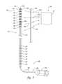
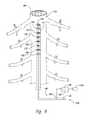
- FIG. 2is a partially schematic illustration of a representative signal delivery device, signal transmission device, and signal detection device, configured in accordance with an embodiment of the disclosure.
- FIG. 3is a partially schematic illustration of a signal detector system positioned over the patient's spine in accordance with an embodiment of the disclosure.
- FIG. 4is an enlarged illustration of a portion of the patient's spinal cord and a representative signal detector device.
- FIG. 5is a schematic illustration of a signal detector system and display for presenting results obtained during procedures in accordance with embodiments of the disclosure.
- FIG. 6is a schematic illustration of an intrathecal penetration detector configured in accordance with an embodiment of the disclosure.
- FIGS. 7A-7Dillustrate processes for implanting patient devices in accordance with several embodiments of the disclosure.
- the present technologyis directed generally to systems and methods for detecting intrathecal penetration in a patient.
- the systems and methodsare used to implant leads proximate to the patient's spinal cord to deliver high frequency signals that modulate neural activity at the patient's spine, in particular embodiments, to address chronic pain.
- the systems and associated methodscan have different configurations, components, and/or procedures. Still other embodiments may eliminate particular components or procedures.
- a person of ordinary skill in the relevant art, therefore, will understand that the present technologymay include other embodiments with additional elements, and/or may include other embodiments without several of the features shown and described below with reference to FIGS. 1A-7D .
- the computing devices on which the described technology can be implementedmay include one or more central processing units, memory, input devices (e.g., input ports), output devices (e.g., display devices), storage devices, and network devices (e.g., network interfaces).
- the memory and storage devicesare computer-readable media that may store instructions that implement the technology.
- the computer readable mediaare tangible media.
- the data structures and message structuresmay be stored or transmitted via an intangible data transmission medium, such as a signal on a communications link.
- Various suitable communications linksmay be used, including but not limited to a local area network and/or a wide-area network.
- FIG. 1Aschematically illustrates a representative patient system 100 for providing relief from chronic pain and/or other conditions, arranged relative to the general anatomy of a patient's spinal cord 191 .
- the overall patient system 100can include a signal delivery system 110 , which may be implanted within a patient 190 , typically at or near the patient's midline 189 , and coupled to a pulse generator 121 .
- the signal delivery system 110can provide therapeutic electrical signals to the patient during operation.
- the overall patient system 100can further include a signal transmission system 130 and a signal detector system 140 .
- the signals handled by the signal transmission system 130 and the signal detector system 140can function primarily to identify the location of the signal delivery system 110 , rather than to provide therapy to the patient.
- the signal transmission system 130 and signal detector system 140can operate independently of the signal delivery system 110 to guide the practitioner as he/she positions elements of the signal delivery system 110 within the patient. Nevertheless, in particular embodiments, certain elements of the signal transmission system 130 can be shared with the signal delivery system 110 . Aspects of the signal delivery system 110 are described immediately below, followed by a description of the signal transmission system 130 and the signal detector system 140 .
- the signal delivery system 110includes a signal delivery device 111 that carries features for delivering therapy to the patient 190 after implantation.
- the pulse generator 121can be connected directly to the signal delivery device 111 , or it can be coupled to the signal delivery device 111 via a signal link 113 (e.g., an extension).
- the signal delivery device 111can include an elongated lead or lead body 112 .
- the terms “lead” and “lead body”include any of a number of suitable substrates and/or support members that carry devices for providing therapy signals to the patient 190 .
- the lead 112can include one or more electrodes or electrical contacts that direct electrical signals into the patient's tissue, such as to provide for patient relief.
- the signal delivery device 111can include structures other than a lead body (e.g., a paddle) that also direct electrical signals and/or other types of signals to the patient 190 .
- the pulse generator 121can transmit signals (e.g., electrical signals) to the signal delivery device 111 that up-regulate (e.g., stimulate or excite) and/or down-regulate (e.g., block or suppress) target nerves.
- signalse.g., electrical signals
- up-regulatee.g., stimulate or excite
- down-regulatee.g., block or suppress
- the terms “modulate” and “modulation”refer generally to signals that have either type of the foregoing effects on the target nerves.
- the pulse generator 121can include a machine-readable (e.g., computer-readable) medium containing instructions for generating and transmitting suitable therapy signals.
- the pulse generator 121 and/or other elements of the system 100can include one or more processors 122 , memories 123 and/or input/output devices.
- the process of providing modulation signals, providing guidance information for locating the signal delivery device 111 , and/or executing other associated functionscan be performed by computer-executable instructions contained by computer-readable media located at the pulse generator 121 and/or other system components.
- the pulse generator 121can include multiple portions, elements, and/or subsystems (e.g., for directing signals in accordance with multiple signal delivery parameters), carried in a single housing, as shown in FIG. 1A , or in multiple housings.
- the pulse generator 121can obtain power to generate the therapy signals from an external power source 118 .
- the external power source 118can transmit power to the implanted pulse generator 121 using electromagnetic induction (e.g., RF signals).
- the external power source 118can include an external coil 119 that communicates with a corresponding internal coil (not shown) within the implantable pulse generator 121 .
- the external power source 118can be portable for ease of use.
- an external programmer 120e.g., a trial modulator
- a practitionere.g., a physician and/or a company representative
- the external programmer 120can vary the modulation parameters provided to the signal delivery device 111 in real time, and select optimal or particularly efficacious parameters. These parameters can include the location from which the electrical signals are emitted, as well as the characteristics of the electrical signals provided to the signal delivery device 111 .
- the practitioneruses a cable assembly 114 to temporarily connect the external programmer 120 to the signal delivery device 111 .
- the practitionercan test the efficacy of the signal delivery device 111 in an initial position.
- the practitionercan then disconnect the cable assembly 114 (e.g., at a connector 117 ), reposition the signal delivery device 111 , and reapply the electrical modulation. This process can be performed iteratively until the practitioner obtains the desired position for the signal delivery device 111 .
- the practitionermay move the partially implanted signal delivery element 111 without disconnecting the cable assembly 114 .
- the practitionercan implant the implantable pulse generator 121 within the patient 190 for longer term treatment.
- the signal delivery parameters provided by the pulse generator 121can still be updated after the pulse generator 121 is implanted, via a wireless physician's programmer 125 (e.g., a physician's remote) and/or a wireless patient programmer 124 (e.g., a patient remote).
- a wireless physician's programmer 125e.g., a physician's remote
- a wireless patient programmer 124e.g., a patient remote
- FIG. 1Bis a cross-sectional illustration of the spinal cord 191 and an adjacent vertebra 195 (based generally on information from Crossman and Neary, “Neuroanatomy,” 1995 (published by Churchill Livingstone)), along with multiple signal delivery devices 111 (shown as signal delivery devices 111 a - d ) implanted at representative locations.
- multiple signal delivery devices 111are shown in FIG. 1B implanted in a single patient. In actual use, any given patient will likely receive fewer than all the signal delivery devices 111 shown in FIG. 1B .
- the spinal cord 191is situated within a vertebral foramen 188 , between a ventrally located ventral body 196 and a dorsally located transverse process 198 and spinous process 197 .
- Arrows V and Didentify the ventral and dorsal directions, respectively.
- the spinal cord 191itself is located within the dura mater 199 , which also surrounds portions of the nerves exiting the spinal cord 191 , including the ventral roots 192 , dorsal roots 193 and dorsal root ganglia 194 .
- a single first signal delivery device 111 ais positioned within the vertebral foramen 188 , at or approximately at the spinal cord midline 189 .
- two second signal delivery devices 111 bare positioned just off the spinal cord midline 189 (e.g., about 1 mm. offset) in opposing lateral directions so that the two signal delivery devices 111 b are spaced apart from each other by about 2 mm.
- a single signal delivery device or pairs of signal delivery devicescan be positioned at other locations, e.g., at the dorsal root entry zone as shown by a third signal delivery device 111 c , or at the dorsal root ganglia 194 , as shown by a fourth signal delivery device 111 d.
- the signal delivery device 111it is important that the signal delivery device 111 be placed at a target location that is expected (e.g., by a practitioner) to produce efficacious results in the patient when activated.
- the following disclosuredescribes techniques and systems for improving the level of accuracy with which the devices are positioned.
- FIG. 2is a partially schematic illustration of a representative signal delivery device 111 that includes a lead 112 carrying a plurality of ring-shaped therapy contacts 126 positioned toward a distal end to deliver a therapy signal to the patient when the lead 112 is implanted.
- the lead 112includes internal wires (not visible in FIG. 2 ) that extend between the therapy contacts 126 at the distal end of the lead 112 , and corresponding connection contacts 127 positioned at the lead proximal end. After implantation, the connection contacts 127 are connected to the external programmer 120 or the implanted pulse generator 121 discussed above with reference to FIG. 1A .
- an implanting tool 160(e.g., a stylet 161 ) is temporarily coupled to the lead 112 to support the lead 112 as it is inserted into the patient.
- the implanting tool 160can include a shaft 162 that is slideably and releasably inserted (via, e.g., a handle 163 ) into an axially-extending opening in the lead 112 .
- the shaft 162is generally flexible, but more rigid than the lead 112 to allow the practitioner to insert the lead 112 and control its position during implantation.
- a stylet stop 128 at the distal end of the lead openingprevents the practitioner from over-inserting the stylet shaft 162 .
- the lead 112 and/or other portions of the overall system 100can include features that guide the practitioner when positioning the lead 112 at a target location.
- the signal transmission system 130can be carried by the lead 112 and/or the implanting tool 160 , and can communicate with the signal detector system 140 located outside the patient's body.
- the signal transmission system 130includes one or more signal transmission devices 131 .
- several different signal transmission devices 131are shown together in FIG. 2 as first, second and third signal transmission devices 131 a , 131 b , 131 c , though in most embodiments, a single or single type of signal transmission device 131 will be implemented.
- the signal transmission devices 131communicate with the signal detector system 140 via corresponding locator signals 132 (shown schematically as first, second and third locator signals 132 a - 132 c ).
- the signal transmission devices 131can generate, emit, and/or reflect the locator signals 132 in a manner that is detected by a signal detector device 141 of the signal detector system 140 .
- the first signal transmission device 131 acan be carried by the lead 112 , and can be independent of (e.g., electrically isolated from) the therapy contacts 126 .
- the second signal transmission device 131 bcan also be carried by the lead 112 , but can double as one of the therapy contacts 126 .
- the second signal transmission device 131 bdoubles as the distal-most therapy contact 126 , located at or near the distal tip of the lead 112 .
- the second signal transmission device 131 bcan double as any of the other therapy contacts 126 .
- the third signal transmission device 131 cis carried by the implanting tool 160 , rather than the lead 112 .
- the third signal transmission device 131 ccan be located at the distal-most tip of the implanting tool 160 .
- An advantageous feature of the first signal transmission device 131 ais that its independence of therapy contacts 126 frees it from being limited by the particular geometry and arrangement of the therapy contacts 126 , which are typically sized, configured and arranged to provide optimal or highly effective and efficient therapy (e.g., modulation) signals. Instead, the first signal transmission device 131 a can be tailored to provide effective and efficient first locator signals 132 a , e.g., in cases where the locator signals differ significantly from the therapy/modulation signals. Conversely, an advantage of combining the functions of the second signal transmission device 131 b with one of the therapy contacts 126 is that it reduces the need for an additional element in the overall patient system 100 .
- signal transmission system 130may comprise only a single or single type of signal transmission device 131 , two such devices or types of devices 131 , or more than three such devices or types of devices 131 in any combination of locations, configurations, and types as herein described.
- the locator signals 132 transmitted by the signal transmission device 131can have any of a variety of characteristics suitable for conveying location information wirelessly through the patient's skin 187 to the signal detector device 141 .
- the locator signal 132can include a radio frequency (RF) signal having a frequency in the range of from about 10 kHz to about 30 GHz.
- RFradio frequency
- the frequency of the locator signal 132is outside the foregoing range.
- the signal transmission device 131can be a magnetic device (e.g., a permanent magnet and/or an electromagnet) and can accordingly transmit locator signals 132 by virtue of magnetic fields, which are detected by the signal detector device 141 .
- the term “locator signal” as used hereinincludes a wide variety of electromagnetic fields and transmissions that can be received or otherwise detected by an appropriate detector device 141 .
- the signalcan be generally constant, as in the case of a magnetic field produced by a permanent magnet, or varying, as in the case of an RF signal.
- the locator signal 132can be an acoustic signal (e.g., ultrasound) that is transmitted by the signal transmission device 131 and received by the signal detector device 141 .
- the locator signalcan actually be emitted from a location external to the patient's body, and the signal detector device 141 can receive or detect an echo or return signal, as indicated by fourth (two-way) locator signals 132 d .
- the term “signal transmission device”includes devices that emit (e.g., actively generate) signals, and devices that reflect signals, with both types of signals selected to be detected by the signal detector device 141 .
- the signal emittercan be co-housed with the signal detector 141 to simplify use.
- the signal delivery device 111 and/or the implanting tool 160can be constructed from materials specifically selected to be highly reflective to ultrasound signals and/or surface treatments to optimize ultrasound reflectivity. Materials having densities different than the densities of the adjacent tissue (which has a significant water content) typically have a higher acoustic impedance and accordingly generate reflections that can be readily distinguished from those produced by the adjacent tissue. Such materials can include polymers such as polyethylene or polyurethane.
- the materialscan include compositions having higher densities and/or materials that are also radiopaque, so that they can be used with a fluoroscopic detection technique and/or an ultrasonic detection technique.
- Suitable materialsinclude platinum, iridium, tantalum, titanium and/or alloys of the foregoing materials.
- the materialscan be applied to one or more of several elements of the signal delivery system 110 , including the therapy contacts 126 , the stylet stop 128 , and/or the end of the stylet shaft 162 , which can have a ball shape (e.g., a welded ball) to inhibit penetration into the distal end of the lead 112 .
- a radiopaque and acoustically reflective ink or other coatingcan be applied to any of the foregoing elements and/or to the outer surface of the stylet shaft 162 and/or to the outer surface of the lead 112 .
- Suitable materialsinclude radiopaque inks available from CJ Medical of Norton, Mass., and sputtered tantalum available from Isoflex Biomed of Rochester, N.Y.
- locator signalsare generally transmitted (e.g., actively or by reflection) from the signal transmission device 131 to the signal detector device 141 .
- signalscan travel in both directions when the detected signal is a reflected signal.
- the signal detector device 141can transmit additional signals to the signal transmission device 131 , e.g., to power the signal transmission device 131 , and/or to query the signal transmission device 131 for additional information.
- the signal detector system 140can include a single detector device 141 , as shown in FIG. 2 .
- the signal detector system 140can include an array 142 or other plurality of detector devices or elements 143 , with each detector element 143 capable of detecting and responding to a locator signal.
- the array 142is positioned on the patient's skin 187 over the patient's spine 184 .
- Each detector element 143can be individually placed on the patient's skin 187 , or the array 142 can include a flexible support member 139 (e.g., a thin plastic or fabric member or single- or multi-layer plastic or fabric composite, etc.) in which all the detector elements 143 are incorporated or located.
- a flexible support member 139e.g., a thin plastic or fabric member or single- or multi-layer plastic or fabric composite, etc.
- some or all detector elements 143may be incorporated between one or more layers thereof and/or affixed to one or both outer surfaces of support member 139 .
- support member 139is a single layer of material, detector elements 143 may be affixed to one or both surfaces of member 139 .
- the support member 139can be releasably attached to the patient's skin 187 , e.g., via an adhesive, straps, or another suitable, releasable attachment mechanism.
- the support member 139can accordingly maintain a constant or generally constant spacing between neighboring detector elements 143 of the array 142 .
- the array 142can include one or more index markers 146 that allow the practitioner to locate the array 142 properly relative to the patient's anatomy. For example, the practitioner can palpate and/or visually identify an anatomic feature 186 of the patient (e.g., the spinous process 197 of a specific vertebra 195 ) and locate the one or more index markers 146 relative to the anatomic feature 186 .
- the detector elements 143can be coupled to a power source 144 that powers the detector elements 143 , and the detector elements 143 can communicate information to other elements of the overall system 100 via a detector output 145 .
- the signal delivery system 110can move in several directions.
- the signal delivery system 110can move axially (or in a rostral/caudal direction) as indicated by arrows 101 , laterally as indicated by arrows 102 and/or in a direct ventral/dorsal direction 103 (viewed end-on in FIG. 3 ).
- the direct ventral/dorsal direction 103corresponds to a direction directly toward or away from the spinal cord.
- the leadmay tend to migrate around the spinal cord in a spiral fashion, as indicated by arrows 104 .
- the detector elements 143 shown in the array 142are positioned in a plane (e.g., a generally flat plane) that contains the axial and lateral axes 101 , 102 , the detector elements 143 tend to be most sensitive to the location of the signal delivery system 110 in these generally orthogonal directions.
- the detector elements 143may not be as sensitive to motion along the ventral/dorsal axis 103 , and/or motion of the signal delivery system 110 wrapping around the spinal cord.
- the overall system 100can include other features that may supplement the information received from the detector elements 143 .
- the overall system 100can include an insertion tracker 150 (shown schematically in FIG.
- the insertion tracker 150can include markings (e.g., a scale) on the signal delivery device 111 or on the implanting tool 160 that the practitioner observes to track the length of the signal delivery device 111 that has been inserted.
- the insertion tracker 150includes a wheel 151 or other suitable mechanical, electromechanical or electro-optic device that automatically determines the length of the signal delivery device 111 inserted into the patient. The inserted length can be presented at a display 152 and/or directed remotely via an output signal 153 .
- the information received by the detector elements 143can be used to estimate a length of the signal delivery device 111 projected into the plane of the array 142 .
- This estimated lengthcan be compared to the length indicated by the insertion tracker 150 , either by the practitioner, or in an automated manner by the overall system 100 , based on the output signal 153 . If the location of the signal delivery device 111 as indicated by the detector elements 143 corresponds to (e.g., is identical or nearly identical to) the inserted length of the signal delivery device 111 identified by the insertion tracker 150 , then the signal delivery device 111 has not likely deviated significantly from a plane located just above the spinal cord.
- the detector elements 143indicate that the signal delivery device 111 is not progressing (or progressing slowly) in the lateral or axial directions, but the insertion tracker 150 indicates that the signal delivery device 111 is in fact progressing (or progressing quickly)
- thiscan indicate to the practitioner that the signal delivery device 111 is traveling out of the plane of the array 142 , e.g., either penetrating toward or into the spinal cord, or wrapping around the spinal cord. Further aspects of this operation are described later with reference to FIG. 5 .
- FIG. 4is a partially schematic illustration of the dorsal region of the patient's spinal cord 191 , with the vertebrae 195 cut away (as shown in cross-section) and with the array 142 of detector elements 143 shown in position over the patient's spine 184 .
- the array 142is typically located on the patient's skin, external to the patient's body, but for purposes of clarity, the patient's skin is not shown in FIG. 4 .
- the detector elements 143present information corresponding to a characteristic of the detected locator signals, in addition to detecting/receiving the locator signals.
- the detector elements 143can each be co-located with a display element 147 and the display elements 143 together can form a display device 170 .
- the display device 170presents information corresponding to the strength of the signal received at individual detector elements 143 .
- the individual display elements 147include an LED or other light source that presents light to the practitioner having a characteristic indicating the signal strength detected at that location.
- the lightcan be brighter at a location where the signal is stronger, and dimmer where the signal is weaker.
- the lightcan have one color where the signal is strong and a different color where the signal is weak.
- the lightcan flash intermittently where the signal is weak and remain steady where the signal is strong (or vice-versa). Combinations of the foregoing characteristics of the light can also be used, with or without other features such as an aural signal indicative of a strong or weak signal. For purposes of illustration, light corresponding to strong signals is indicated in FIG. 4 with a heavier shading.
- the signal delivery device 111has been advanced along the patient's spinal cord 191 via an implanting tool 160 that carries a signal transmission device 131 at its distal tip. Accordingly, the display elements 147 located closest to the signal transmission device 131 indicate the highest strength signal, and those further away from the signal transmission device 131 identify weaker signals. In some cases, the practitioner may position the signal delivery device 111 so that the signal transmission device 131 is aligned at a selected target location (e.g., a first target location 185 a ).
- a selected target locatione.g., a first target location 185 a
- the target location(e.g., a second target location 185 b ) may be located apart from the signal emission device 131 , for example, in cases for which the practitioner deliberately wishes to have a part of the signal delivery device 111 other than the distal-most tip aligned with the second target location 185 b .
- the practitionercan use the information presented by the display elements 147 to locate the signal transmission device 131 and, by knowing the relative spacing between the signal transmission device 131 and each of the therapy contacts 126 , can locate any given therapy contact 126 with equal or generally equal accuracy.
- the display elements 147present information corresponding to the location of the signal transmission device 131 in situ, directly on the patient's skin overlying the spine. In other embodiments, this information can be presented at a remote location, in addition to, or in lieu of being presented in situ.
- FIG. 5illustrates a signal detector system 140 that displays information at a position spaced apart from the detector elements 143 (shown in FIG. 4 ).
- the signal detector system 140includes a processor 148 and a memory 149 that receive and store signal detector output 145 from the detector elements 143 , and receive and store insertion tracker output 153 from the insertion tracker 150 ( FIG. 4 ).
- This informationis processed (e.g., via instructions contained by a computer-readable medium) and presented at a display device 170 a , e.g., an LCD or LED screen.
- the display device 170 acan include a graphical depiction of the patient's spinal cord midline via a midline indicator 171 and can graphically display detector element indicators 172 which are spaced apart from each other in a manner that corresponds to the spacing of the detector elements 143 on the patient's back.
- the detector element indicators 172can be illuminated or otherwise presented in a manner that distinguishes strong detected signals from weaker detected signals, e.g, as previously described with respect to the embodiment of FIG. 4 .
- the display device 170 acan present a signal delivery device indicator 173 that represents the location of the signal delivery device as determined by the signal detector system 140 , based on the information received at the detector elements 143 (e.g., using a suitable interpolation scheme). Accordingly, the practitioner can view the display device 170 a to obtain a graphical presentation of the location of the signal delivery device (which is not visible) relative to the patient's midline and the receiver elements 143 (which are visible).
- the foregoing information received from the detector elements 143can be combined with information received via the insertion tracker output 153 to indicate when the signal delivery device 111 ( FIG. 4 ) moves out of plane. As discussed above, it is expected that the signal delivery device 111 will be out of plane when the lead length determined via the array 142 of detector elements 143 is less than the lead length determined by the insertion tracker 150 . This information can be presented via an out-of-plane indicator 174 that illuminates when the lead is out of plane. This information can also be conveyed to the practitioner via an inserted length display 176 which compares the calculated length of the signal delivery device in the plane of the array 142 , with the measured length of the signal delivery device actually inserted into the patient. The information presented at the display device 170 a can still further include an intrathecal penetration indicator 175 , which indicates that the dura around the spinal cord has been penetrated. Further information corresponding to this aspect of the system is described further below with reference to FIG. 6 .
- FIG. 6schematically illustrates an intrathecal penetration detector 180 that can be used alone or in conjunction with other features of the overall patient system 100 described above to aid the practitioner in identifying the location of the signal delivery device 111 .
- the intrathecal penetration detector 180take advantage of the low impedance that cerebral spinal fluid (CSF) has relative to the surrounding tissue in the spinal cord region.
- CSFcerebral spinal fluid
- the intrathecal penetration detector 180can use the impedance difference between CSF and the surrounding tissue to determine whether the dura 199 around the spinal cord 191 has been penetrated.
- the intrathecal penetration detector 180can detect an unexpectedly low impedance of a circuit that includes the signal delivery device 111 and the adjacent patient tissue, and identify this event to the practitioner as an indication that the signal delivery device 111 has potentially damaged or penetrated through the dura 199 of the patient's spinal cord 191 . In most applications, it is undesirable to penetrate the dura 199 and therefore providing an indication of intrathecal penetration can allow the practitioner to withdraw and reposition the signal delivery device 111 , optionally repair the damaged dura 199 , and complete the process of implanting the signal delivery device 111 .
- the intrathecal penetration detector 180includes a power source 181 that applies a detection signal to a detection circuit 183 .
- the detection circuit 183includes patient tissue, and can further include one or more of the therapy contacts 126 in contact with the patient tissue. Using the therapy contacts 126 as part of the impedance circuit 183 reduces the need for adding additional features to the signal delivery device 111 ; nevertheless, in another embodiment, the signal delivery device 111 can carry contacts that are dedicated to impedance detection.
- the detection circuit 183can include two selected therapy contacts 126 and the patient tissue located between the two therapy contacts 126 .
- the detection circuit 183can include a single therapy contact 126 and ground (e.g., a patient ground pad).
- the intrathecal penetration detector 180further includes an impedance detector 182 in the detection circuit 183 that identifies the impedance of the circuit 183 .
- the impedance detector 182can be connected to the processor 148 , memory 149 , and display device 170 a described above with reference to FIG. 5 or to another processor and/or output device.
- the power source 181provides a detection signal (e.g., a pulsed subthreshold signal with a current amplitude of about 0.2 milliamps, a pulse width of about 80 microseconds).
- the detection signalcan be subthreshold to avoid inadvertently stimulating the patients' motor and/or sensory neural pathways.
- the pulsescan be delivered in bursts at any suitable frequency, e.g., a frequency provided by the external programmer 120 ( FIG. 1A ).
- the frequencycan coincide with a representative therapy frequency (e.g., about 3 kHz to about 50 kHz) and in other embodiments, can have other values.
- the impedance of a circuit that includes two therapy contacts 126will have an impedance of less than 1000 ohms, and typically an impedance in the range of about 300 ohms to about 600 ohms. If the impedance falls below a first threshold (e.g., about 200 ohms), the detector 180 and/or other elements of the system 100 can issue a warning, calling the practitioner's attention to the possibility of a CSF leak.
- a first thresholde.g., about 200 ohms
- the detector 180 and/or other elements of the system 100can indicate a likely intrathecal penetration by the contact(s) 126 a that are included in the detection circuit 183 . As discussed above with reference to FIG. 5 , this indication can be presented at the display device 170 . In other embodiments, the indication can be presented in other manners, e.g., aurally. In still further embodiments, the foregoing threshold levels may have different values.
- the “typical” impedancemay fall from 300-600 ohms to 180 ohms, in which case the practitioner may require a lower threshold level (e.g., 150 ohms rather than 200 ohms) for an indication of CSF leakage.
- the “typical” impedancemay be much larger than 1000 ohms, e.g., 200 ohms.
- the practitionercan select from any of the therapy contacts 126 to be included in the impedance detection circuit 183 .
- the practitionermay wish to include the distal-most therapy contact (e.g., at the distal tip of the signal delivery device 111 ) in the detection circuit 183 to provide an early indication that the signal delivery device 111 has penetrated the dura 199 . If the signal delivery device 111 does not include a therapy contact 126 at the tip, a special-purpose contact can be added to the signal delivery device 111 , or the practitioner can use the therapy contact 126 closest to the tip. In other embodiments, the practitioner may wish to include one or more of the other therapy contacts 126 in the circuit, for example, to identify the extent and/or rate of a cerebral spinal fluid leak, and/or for other diagnostic purposes.
- the information received from the impedance detector 182can be processed to indicate to the practitioner whether or not the dura 199 has been penetrated.
- the informationcan be provided in a fairly straightforward manner, e.g., by indicating either no intrathecal penetration or intrathecal penetration, optionally with an intermediate indication of likely CSF leakage.
- the intrathecal penetration detector 180can provide more sophisticated information.
- the intrathecal penetration detector 180can employ a multiplex arrangement or other suitable signal processing arrangement to scan over the therapy contacts 126 and identify issues or insipient issues associated with any of the contacts 126 .
- the intrathecal penetration detector 180can track a rate at which a drop in impedance passes along the signal delivery device 111 (e.g., as detected by multiple therapy contacts 126 ) to provide the practitioner with an indication of the rate at which CSF is leaking from the dura 199 .
- the intrathecal penetration detector 180can include other arrangements.
- the intrathecal penetration detector 180can indicate which contacts(s) 126 have lower than expected associated impedance.
- the tip of the signal delivery devicemay penetrate the dura 199 by breaking the continuity of the dura 199 without actually proceeding into the subdural space.
- Leaking CSFmay then be indicated by low impedances at proximal therapy contacts 126 as they pass by the break in the dura 199 , and/or as CSF flows in a proximal direction, but a normal impedance (at least for a period of time) at the distalmost therapy contact 126 .
- FIGS. 7A-7Dillustrate flow diagrams of methods in accordance with several embodiments of the disclosure described above. As described above, many of the steps in these methods may be performed automatically by instructions contained in one or more computer readable media.
- FIG. 7Aillustrates a process 700 a that includes, for each of a plurality of patients, receiving a target location from which to deliver a modulation signal to the patient's spinal cord (process portion 701 a ).
- the target locationcan be a single location or one of multiple locations, and can have axial and lateral coordinates selected to produce a desired patient effect.
- the process 700 acan further include implanting a signal delivery device within a vertebral foramen of the patient, and positioning an electrical contact carried by the signal delivery device to be within ⁇ 5 mm.
- this accuracy levelcan be obtained in the axial and/or lateral directions via a single signal detector or via an array of detector elements.
- the same level of accuracycan be obtained in the dorsal/ventral direction, e.g., via an insertion tracker or other suitable methodology.
- the practitionercan use electromagnetic techniques (e.g., RF or magnetic techniques) or ultrasound techniques to accurately implant the signal delivery device on a consistent, repeatable basis over multiple patients (e.g., a patient population numbering in the tens or hundreds or more).
- the accuracy of this methodcan be better than ⁇ 5 mm., e.g., ⁇ 2 mm. or ⁇ 1 mm., depending on factors that include, but are not limited to, the sensitivity of the signal detector or signal detector elements, the unidirectionality of the signal transmitters, and the spacing between signal detector elements.
- the ability to locate the signal delivery device within the foregoing ranges without the use of fluoroscopycan simplify the implanting process, and can reduce the patient's exposure to x-ray radiation.
- fluoroscopy devicescan be cumbersome and, due to the protective gear worn by the practitioner, can interfere with the practitioner's freedom of movement.
- fluoroscopy equipmentis generally expensive and not generally available in remote and/or developing parts of the world.
- the current technologycan reduce or eliminate the dependence on fluoroscopy for accurate device placement which can in turn allow the device and associated therapy to be used in a larger number of treatment centers (i.e., those without fluoroscopic equipment) and a concomitant potentially greater number of patients in need of such therapy.
- the process 700 acan be performed with less or no patient feedback (process portion 704 a ).
- the increased accuracy with which the signal delivery device is implanted in the first instancecan reduce the number of subsequent iterations the practitioner and patient engage in to identify an effective location for the signal delivery device and associated therapy contacts.
- Such iterationscan include moving the signal delivery device and/or selecting different active contacts on the signal delivery device.
- the signal delivery devicecan be activated to modulate neural activity at the spinal cord (process portion 705 a ).
- the therapyincludes RF signals delivered to the patient's spinal cord at a frequency of from about 3 kHz to about 50 kHz to address patient pain. Further details of suitable signal delivery parameters are included in pending U.S. patent application Ser. No. 12/765,747, filed on Apr. 22, 2010 and incorporated herein by reference in its entirety.
- the signal delivery devicecan provide signals in accordance with other signal delivery parameters to treat the same or other patient indications, at the same or other implantation sites.
- FIG. 7Bis a flow diagram illustrating a process 700 b in accordance with another embodiment of the disclosure, which includes implanting an implantable signal delivery system beneath the patient's skin and into a vertebral foramen of at least one of the patient's vertebrae (process portion 701 b ).
- the signal delivery systemincludes a signal delivery device having at least one electrical contact.
- a locator signalis emitted from the signal delivery system.
- the locator signalcan be emitted from the signal delivery device and/or from an implanting tool that temporarily carries the signal delivery device during an implanting process.
- the locator signalis detected from a position external to the patient.
- the locator signalcan be detected at a plurality of locations via an array of signal detectors (process portion 704 b ).
- the resultscan be presented at a display indicating the relative signal strength received at the signal detectors (process portion 705 b ).
- the practitionercan adjust a position of the signal delivery device relative to the patient's spinal cord (process portion 706 b ) and the practitioner can then direct a therapy signal from the electrical contact (process portion 707 b ).
- an advantage of methods performed in accordance with the flow diagram shown in FIG. 7Bis that they can allow the practitioner to accurately position the signal delivery device, e.g., without using fluoroscopy.
- FIG. 7Cillustrates another process 700 c in accordance with an embodiment of the disclosure that includes receiving a plurality of indications of the strength of a locator signal from a corresponding plurality of signals detectors (process portion 701 c ).
- the signal detectorsare positioned in an array external to the patient to form a plane extending laterally and in a rostral/caudal direction (e.g., an axial direction).
- a first lengthe.g., a projected length of an implanted portion of the signal delivery device in the plane of the array
- an indication of the second length (e.g., an actual length) of the implanted portion of the signal delivery deviceis received.
- process portion 703 ccan include receiving an indication of the actual implanted length via the insertion tracker discussed above with reference to FIG. 6 .
- the second length of the implanted portion of the leadis compared with the first length and, based on a difference between the actual length and the projected length, an indication of a ventral/dorsal location of the signal delivery system is provided. For example, if the actual and projected lengths differ by more than a threshold amount (e.g., one mm. in one embodiment and other values in other embodiments), the foregoing indication can be triggered.
- a threshold amounte.g., one mm. in one embodiment and other values in other embodiments
- FIG. 7Dillustrates a process 700 d that may be used independently of or in conjunction with any of the foregoing methods described above with reference to FIGS. 7A-7C .
- the process 700 dincludes introducing an electrical contact into a patient, proximate to the patient's dura (process portion 701 d ).
- process portion 702 dan impedance of an electrical circuit that includes the electrical contact and patient tissue adjacent to the electrical contact is detected.
- Process portion 703 dincludes comparing the detected impedance to a predetermined criterion (e.g., a threshold impedance value).
- a predetermined criterione.g., a threshold impedance value
- the process 700 dcan include identifying penetration of the patient's dura based at least in part on the detected impedance (process portion 704 d ).
- penetrationcan include breaking the continuity of the dura, whether or not the electrical contact actually passes through the dura to an intrathecal location.
- the predetermined criterioncan include an impedance value at or below which detected impedances correspond to exposure to cerebral spinal fluid.
- the foregoing systems and methodscan be used to locate devices other than spinal cord implants.
- the intrathecal detection device and methodology described abovecan be applied to other areas of the patient's body that are surrounded by the dura and contain cerebral spinal fluid, for example, the brain.
- these devices and methodologiescan be applied to implantable patient devices other than neural modulators (e.g., other elements configured for patient implantation, with therapy contacts in at least some cases).
- the implanting tools described abovecan have configurations other than a stylet (e.g., a catheter) in other embodiments.
- the locator signal emitters and/detectorscan be omnidirectional in certain embodiments or can be unidirectional in other embodiments.
- phase shift and/or phased array techniquescan be implemented to enhance system efficacy.
- the signal delivery systemcan include one transmission device in certain embodiments, and more than one transmission device in other embodiments.
- the display 170 a described above with reference to FIG. 5may in some embodiments be made thin and flexible enough to be placed directly on the patient's body, with the detector elements integrated into the display medium. Accordingly, the practitioner can obtain the benefit of a graphical representation of the implanted signal delivery device, together with the proximity of the display to the actual location of the signal delivery device.
- the use of an aural indicator described above in the context of the intrathecal penetration detectorcan be applied to the technique for locating the signal delivery device relative to other motion axes, in addition to or in lieu of presenting the information via a visual display.
- the aural indicationcan be triggered if the signal delivery device exceeds a threshold distance from the patient's midline.
Landscapes
- Health & Medical Sciences (AREA)
- Life Sciences & Earth Sciences (AREA)
- Radiology & Medical Imaging (AREA)
- Engineering & Computer Science (AREA)
- Biomedical Technology (AREA)
- Nuclear Medicine, Radiotherapy & Molecular Imaging (AREA)
- Animal Behavior & Ethology (AREA)
- General Health & Medical Sciences (AREA)
- Public Health (AREA)
- Veterinary Medicine (AREA)
- Neurology (AREA)
- Neurosurgery (AREA)
- Heart & Thoracic Surgery (AREA)
- Physics & Mathematics (AREA)
- Pathology (AREA)
- Biophysics (AREA)
- Medical Informatics (AREA)
- Molecular Biology (AREA)
- Surgery (AREA)
- Orthopedic Medicine & Surgery (AREA)
- Cardiology (AREA)
- Pain & Pain Management (AREA)
- Surgical Instruments (AREA)
- Measurement And Recording Of Electrical Phenomena And Electrical Characteristics Of The Living Body (AREA)
- Measurement Of Resistance Or Impedance (AREA)
Abstract
Description
Claims (24)
Priority Applications (2)
| Application Number | Priority Date | Filing Date | Title |
|---|---|---|---|
| US14/326,301US9358388B2 (en) | 2010-09-30 | 2014-07-08 | Systems and methods for detecting intrathecal penetration |
| US15/140,039US10279183B2 (en) | 2010-09-30 | 2016-04-27 | Systems and methods for detecting intrathecal penetration |
Applications Claiming Priority (2)
| Application Number | Priority Date | Filing Date | Title |
|---|---|---|---|
| US12/895,438US8805519B2 (en) | 2010-09-30 | 2010-09-30 | Systems and methods for detecting intrathecal penetration |
| US14/326,301US9358388B2 (en) | 2010-09-30 | 2014-07-08 | Systems and methods for detecting intrathecal penetration |
Related Parent Applications (1)
| Application Number | Title | Priority Date | Filing Date |
|---|---|---|---|
| US12/895,438DivisionUS8805519B2 (en) | 2010-09-30 | 2010-09-30 | Systems and methods for detecting intrathecal penetration |
Related Child Applications (1)
| Application Number | Title | Priority Date | Filing Date |
|---|---|---|---|
| US15/140,039ContinuationUS10279183B2 (en) | 2010-09-30 | 2016-04-27 | Systems and methods for detecting intrathecal penetration |
Publications (2)
| Publication Number | Publication Date |
|---|---|
| US20150012077A1 US20150012077A1 (en) | 2015-01-08 |
| US9358388B2true US9358388B2 (en) | 2016-06-07 |
Family
ID=45890401
Family Applications (3)
| Application Number | Title | Priority Date | Filing Date |
|---|---|---|---|
| US12/895,438Active2033-06-04US8805519B2 (en) | 2010-09-30 | 2010-09-30 | Systems and methods for detecting intrathecal penetration |
| US14/326,301ActiveUS9358388B2 (en) | 2010-09-30 | 2014-07-08 | Systems and methods for detecting intrathecal penetration |
| US15/140,039Active2031-05-13US10279183B2 (en) | 2010-09-30 | 2016-04-27 | Systems and methods for detecting intrathecal penetration |
Family Applications Before (1)
| Application Number | Title | Priority Date | Filing Date |
|---|---|---|---|
| US12/895,438Active2033-06-04US8805519B2 (en) | 2010-09-30 | 2010-09-30 | Systems and methods for detecting intrathecal penetration |
Family Applications After (1)
| Application Number | Title | Priority Date | Filing Date |
|---|---|---|---|
| US15/140,039Active2031-05-13US10279183B2 (en) | 2010-09-30 | 2016-04-27 | Systems and methods for detecting intrathecal penetration |
Country Status (2)
| Country | Link |
|---|---|
| US (3) | US8805519B2 (en) |
| WO (1) | WO2012044699A2 (en) |
Cited By (4)
| Publication number | Priority date | Publication date | Assignee | Title |
|---|---|---|---|---|
| US10279183B2 (en) | 2010-09-30 | 2019-05-07 | Nevro Corp. | Systems and methods for detecting intrathecal penetration |
| US10980999B2 (en) | 2017-03-09 | 2021-04-20 | Nevro Corp. | Paddle leads and delivery tools, and associated systems and methods |
| US11065461B2 (en) | 2019-07-08 | 2021-07-20 | Bioness Inc. | Implantable power adapter |
| US11420045B2 (en) | 2018-03-29 | 2022-08-23 | Nevro Corp. | Leads having sidewall openings, and associated systems and methods |
Families Citing this family (76)
| Publication number | Priority date | Publication date | Assignee | Title |
|---|---|---|---|---|
| US8326439B2 (en) | 2008-04-16 | 2012-12-04 | Nevro Corporation | Treatment devices with delivery-activated inflatable members, and associated systems and methods for treating the spinal cord and other tissues |
| WO2009143177A2 (en)* | 2008-05-19 | 2009-11-26 | Nevro Corporation | Implantable neural stimulation electrode assemblies and methods for stimulating spinal neural sites |
| EP2320990B2 (en)* | 2008-08-29 | 2023-05-31 | Corindus, Inc. | Catheter control system and graphical user interface |
| US9403020B2 (en) | 2008-11-04 | 2016-08-02 | Nevro Corporation | Modeling positions of implanted devices in a patient |
| US8965482B2 (en) | 2010-09-30 | 2015-02-24 | Nevro Corporation | Systems and methods for positioning implanted devices in a patient |
| US10758723B2 (en) | 2011-05-19 | 2020-09-01 | Neuros Medical, Inc. | Nerve cuff electrode for neuromodulation in large human nerve trunks |
| US11413458B2 (en) | 2011-05-19 | 2022-08-16 | Neuros Medical, Inc. | Nerve cuff electrode for neuromodulation in large human nerve trunks |
| US9295841B2 (en) | 2011-05-19 | 2016-03-29 | Meuros Medical, Inc. | High-frequency electrical nerve block |
| WO2012159002A2 (en) | 2011-05-19 | 2012-11-22 | Neuros Medical, Inc. | High-frequency electrical nerve block |
| AU2013211937B2 (en) | 2012-01-25 | 2016-07-28 | Nevro Corporation | Lead anchors and associated systems and methods |
| WO2013111137A2 (en) | 2012-01-26 | 2013-08-01 | Rainbow Medical Ltd. | Wireless neurqstimulatqrs |
| US8676331B2 (en) | 2012-04-02 | 2014-03-18 | Nevro Corporation | Devices for controlling spinal cord modulation for inhibiting pain, and associated systems and methods, including controllers for automated parameter selection |
| US9339655B2 (en) | 2012-06-30 | 2016-05-17 | Boston Scientific Neuromodulation Corporation | System and method for compounding low-frequency sources for high-frequency neuromodulation |
| US9002459B2 (en) | 2012-09-19 | 2015-04-07 | Boston Scientific Neuromodulation Corporation | Method for selectively modulating neural elements in the dorsal horn |
| WO2014087337A1 (en) | 2012-12-06 | 2014-06-12 | Bluewind Medical Ltd. | Delivery of implantable neurostimulators |
| US9446243B2 (en) | 2012-12-07 | 2016-09-20 | Boston Scientific Neuromodulation Corporation | Patient posture determination and stimulation program adjustment in an implantable stimulator device using impedance fingerprinting |
| US9308022B2 (en) | 2012-12-10 | 2016-04-12 | Nevro Corporation | Lead insertion devices and associated systems and methods |
| US9358391B2 (en) | 2013-02-22 | 2016-06-07 | Boston Scientific Neuromodulation Corporation | Neurostimulation system having increased flexibility for creating complex pulse trains |
| US9174053B2 (en) | 2013-03-08 | 2015-11-03 | Boston Scientific Neuromodulation Corporation | Neuromodulation using modulated pulse train |
| US20140277267A1 (en) | 2013-03-15 | 2014-09-18 | Boston Scientific Neuromodulation Corporation | Neuromodulation system and method for transitioning between programming modes |
| WO2014144785A1 (en) | 2013-03-15 | 2014-09-18 | The Regents Of The University Of California | Multi-site transcutaneous electrical stimulation of the spinal cord for facilitation of locomotion |
| US9180297B2 (en) | 2013-05-16 | 2015-11-10 | Boston Scientific Neuromodulation Corporation | System and method for spinal cord modulation to treat motor disorder without paresthesia |
| US10029102B2 (en) | 2013-06-06 | 2018-07-24 | Boston Scientific Neuromodulation Corporation | System and method for delivering modulated sub-threshold therapy to a patient |
| US9950173B2 (en) | 2013-06-06 | 2018-04-24 | Boston Scientific Neuromodulation Corporation | System and method for delivering sub-threshold and super-threshold therapy to a patient |
| CN105358214B (en) | 2013-06-28 | 2017-05-17 | 波士顿科学神经调制公司 | Electrode selection for sub-threshold modulation therapy |
| US9265935B2 (en) | 2013-06-28 | 2016-02-23 | Nevro Corporation | Neurological stimulation lead anchors and associated systems and methods |
| CN105407964B (en) | 2013-07-26 | 2018-05-04 | 波士顿科学神经调制公司 | A system that provides modulation therapy without perception |
| US10137299B2 (en) | 2013-09-27 | 2018-11-27 | The Regents Of The University Of California | Engaging the cervical spinal cord circuitry to re-enable volitional control of hand function in tetraplegic subjects |
| JP6137722B2 (en) | 2013-10-30 | 2017-05-31 | ボストン サイエンティフィック ニューロモデュレイション コーポレイション | Split control to avoid dorsal root stimulation |
| EP3062876A1 (en) | 2013-10-31 | 2016-09-07 | Boston Scientific Neuromodulation Corporation | System to incorporate lead information from image |
| US9358396B2 (en) | 2013-11-01 | 2016-06-07 | Boston Scientific Neuromodulation Corporation | Systems and methods for delivering sub-threshold therapy to a patient at a physiological midline |
| US10010715B2 (en) | 2013-12-04 | 2018-07-03 | Boston Scientific Neuromodulation Corporation | Systems and methods for delivering therapy to the dorsal horn of a patient |
| US9616230B2 (en) | 2013-12-12 | 2017-04-11 | Boston Scientific Neuromodulation Corporation | Systems and methods for programming a neuromodulation system |
| AU2015214522B2 (en) | 2014-02-05 | 2017-08-31 | Boston Scientific Neuromodulation Corporation | System and method for delivering modulated sub-threshold therapy to a patient |
| US9381360B2 (en) | 2014-02-05 | 2016-07-05 | Boston Scientific Neuromodulation Corporation | System and method for delivering modulated sub-threshold therapy to a patient |
| JP6437019B2 (en) | 2014-07-03 | 2018-12-12 | ボストン サイエンティフィック ニューロモデュレイション コーポレイション | Nerve stimulation system with flexible pattern formation and waveform |
| US9662495B2 (en) | 2014-07-24 | 2017-05-30 | Boston Scientific Neuromodulation Corporation | Enhanced dorsal horn stimulation using multiple electrical fields |
| US9737717B2 (en) | 2014-09-15 | 2017-08-22 | Boston Scientific Neuromodulation Corporation | Graphical user interface for programming neurostimulation pulse patterns |
| WO2016048756A1 (en) | 2014-09-23 | 2016-03-31 | Boston Scientific Neuromodulation Corporation | System for calibrating dorsal horn stimulation |
| WO2016048965A1 (en) | 2014-09-23 | 2016-03-31 | Boston Scientific Neuromodulation Corporation | Neuromodulation with burst stimulation |
| JP6564851B2 (en) | 2014-09-23 | 2019-08-21 | ボストン サイエンティフィック ニューロモデュレイション コーポレイション | Short pulse width stimulation |
| WO2016048968A2 (en) | 2014-09-23 | 2016-03-31 | Boston Scientific Neuromodulation Corporation | Systems and methods for receiving user-provided selection of electrode lists |
| WO2016048967A1 (en) | 2014-09-23 | 2016-03-31 | Boston Scientific Neuromodulation Corporation | Perception calibration of neural tissue using field troll |
| EP3197542A1 (en) | 2014-09-23 | 2017-08-02 | Boston Scientific Neuromodulation Corporation | Neuromodulation specific to objective function of modulation field for targeted tissue |
| US9993646B2 (en) | 2014-09-23 | 2018-06-12 | Boston Scientific Neuromodulation Corporation | Sub-perception modulation responsive to patient input |
| JP6452836B2 (en) | 2014-11-04 | 2019-01-16 | ボストン サイエンティフィック ニューロモデュレイション コーポレイション | Method and apparatus for programming complex neural stimulation patterns |
| US10213148B2 (en)* | 2014-12-05 | 2019-02-26 | Pacesetter, Inc. | Spinal cord stimulation guidance system and method of use |
| CN107405484B (en) | 2015-02-09 | 2021-09-24 | 波士顿科学神经调制公司 | System for Determining Nerve Location of Epidural Leads |
| US9789321B2 (en) | 2015-04-03 | 2017-10-17 | Nevro Corp. | Couplings for implanted leads and external stimulators, and associated systems and methods |
| US9827422B2 (en) | 2015-05-28 | 2017-11-28 | Boston Scientific Neuromodulation Corporation | Neuromodulation using stochastically-modulated stimulation parameters |
| AU2016297965B2 (en) | 2015-07-30 | 2019-04-04 | Boston Scientific Neuromodulation Corporation | User interface for custom patterned electrical stimulation |
| WO2017066187A1 (en) | 2015-10-15 | 2017-04-20 | Boston Scientific Neuromodulation Corporation | User interface for neurostimulation waveform composition |
| US10105540B2 (en) | 2015-11-09 | 2018-10-23 | Bluewind Medical Ltd. | Optimization of application of current |
| US10780274B2 (en) | 2016-08-22 | 2020-09-22 | Boston Scientific Neuromodulation Corporation | Systems and methods for delivering spinal cord stimulation therapy |
| US10124178B2 (en) | 2016-11-23 | 2018-11-13 | Bluewind Medical Ltd. | Implant and delivery tool therefor |
| CN110121375B (en)* | 2016-12-23 | 2024-02-02 | 洛桑联邦理工学院 | Sensory information compliant spinal cord stimulation system for motor function recovery |
| US11235154B2 (en) | 2017-02-17 | 2022-02-01 | The University Of British Columbia | Apparatus and methods for maintaining physiological functions |
| WO2018217791A1 (en) | 2017-05-23 | 2018-11-29 | The Regents Of The University Of California | Accessing spinal networks to address sexual dysfunction |
| US20180353764A1 (en) | 2017-06-13 | 2018-12-13 | Bluewind Medical Ltd. | Antenna configuration |
| EP3974021B1 (en) | 2017-06-30 | 2023-06-14 | ONWARD Medical N.V. | A system for neuromodulation |
| US12357828B2 (en) | 2017-12-05 | 2025-07-15 | Ecole Polytechnique Federale De Lausanne (Epfl) | System for planning and/or providing neuromodulation |
| EP3723840B1 (en) | 2017-12-13 | 2022-11-30 | Neuros Medical, Inc. | Nerve cuff deployment devices |
| EP3773876B1 (en) | 2018-04-09 | 2024-04-17 | Neuros Medical, Inc. | Apparatuses for setting an electrical dose |
| US11247046B2 (en) | 2018-07-24 | 2022-02-15 | Synerfuse, Inc. | Methods and systems for implanting a neuromodulation system at a surgically open spinal treatment site |
| DE18205821T1 (en) | 2018-11-13 | 2020-12-24 | Gtx Medical B.V. | CONTROL SYSTEM FOR MOTION RECONSTRUCTION AND / OR RECOVERY FOR A PATIENT |
| EP3653260A1 (en) | 2018-11-13 | 2020-05-20 | GTX medical B.V. | Sensor in clothing of limbs or footwear |
| EP3695878B1 (en) | 2019-02-12 | 2023-04-19 | ONWARD Medical N.V. | A system for neuromodulation |
| CN112206400B (en) | 2019-07-12 | 2025-02-28 | 巴德阿克塞斯系统股份有限公司 | Catheter tracking and placement system including a light emitting diode array |
| US10906188B1 (en)* | 2019-10-25 | 2021-02-02 | Dexterity, Inc. | Singulation of arbitrary mixed items |
| DE19211698T1 (en) | 2019-11-27 | 2021-09-02 | Onward Medical B.V. | Neuromodulation system |
| EP3827875B1 (en) | 2019-11-27 | 2023-07-05 | ONWARD Medical N.V. | Neuromodulation system |
| AU2021219722A1 (en) | 2020-02-11 | 2022-09-08 | Neuros Medical, Inc. | System and method for quantifying qualitative patient-reported data sets |
| US11878167B2 (en) | 2020-05-04 | 2024-01-23 | Btl Healthcare Technologies A.S. | Device and method for unattended treatment of a patient |
| WO2021224678A1 (en) | 2020-05-04 | 2021-11-11 | Btl Medical Technologies S.R.O. | Device and method for unattended treatment of a patient |
| EP3909640A1 (en)* | 2020-05-12 | 2021-11-17 | Surgicen SLU | Medical device for spinal cord stimulation |
| US11400299B1 (en) | 2021-09-14 | 2022-08-02 | Rainbow Medical Ltd. | Flexible antenna for stimulator |
Citations (514)
| Publication number | Priority date | Publication date | Assignee | Title |
|---|---|---|---|---|
| US3195540A (en) | 1963-03-29 | 1965-07-20 | Louis C Waller | Power supply for body implanted instruments |
| US3724467A (en) | 1971-04-23 | 1973-04-03 | Avery Labor Inc | Electrode implant for the neuro-stimulation of the spinal cord |
| US3774618A (en) | 1972-07-03 | 1973-11-27 | Avery Labor Inc | Implantable nerve stimulation electrode |
| US3796221A (en) | 1971-07-07 | 1974-03-12 | N Hagfors | Apparatus for delivering electrical stimulation energy to body-implanted apparatus with signal-receiving means |
| US4096866A (en) | 1976-04-30 | 1978-06-27 | The Johns Hopkins University | Rechargeable body tissue stimulator with back-up battery and pulse generator |
| US4136703A (en) | 1978-03-09 | 1979-01-30 | Vitatron Medical B.V. | Atrial lead and method of inserting same |
| US4141365A (en) | 1977-02-24 | 1979-02-27 | The Johns Hopkins University | Epidural lead electrode and insertion needle |
| US4282886A (en) | 1979-11-13 | 1981-08-11 | Medtronic, Inc. | Adhesive bonded positive fixation epicardial lead |
| US4328813A (en) | 1980-10-20 | 1982-05-11 | Medtronic, Inc. | Brain lead anchoring system |
| US4355224A (en) | 1980-08-15 | 1982-10-19 | Huntington Alloys, Inc. | Coated electrode |
| US4422917A (en) | 1980-09-10 | 1983-12-27 | Imi Marston Limited | Electrode material, electrode and electrochemical cell |
| US4432377A (en) | 1982-01-29 | 1984-02-21 | Medtronic, Inc. | Biomedical lead with ring electrode and method of making same |
| US4462401A (en) | 1982-11-15 | 1984-07-31 | Minnesota Mining And Manufacturing Company | Method and anchor for anchoring electrode leads used in cochlear implantation |
| US4462402A (en) | 1982-11-15 | 1984-07-31 | Minnesota Mining And Manufacturing Company | Method and anchor for anchoring |
| US4465079A (en) | 1982-10-13 | 1984-08-14 | Medtronic, Inc. | Biomedical lead with fibrosis-inducing anchoring strand |
| US4466690A (en) | 1981-06-24 | 1984-08-21 | Peter Osypka | Connector for the conductors of implanted medical devices |
| US4498482A (en) | 1979-12-13 | 1985-02-12 | Medtronic, Inc. | Transvenous pacing lead having improved stylet |
| US4515168A (en) | 1983-07-22 | 1985-05-07 | Chester Martin H | Clamp-on nerve stimulator and locator |
| US4538624A (en) | 1982-12-08 | 1985-09-03 | Cordis Corporation | Method for lead introduction and fixation |
| EP0158316A2 (en) | 1984-04-10 | 1985-10-16 | Walsh Manufacturing (Mississauga) Limited | Anastomosis devices and kit |
| US4573448A (en) | 1983-10-05 | 1986-03-04 | Pilling Co. | Method for decompressing herniated intervertebral discs |
| US4573481A (en) | 1984-06-25 | 1986-03-04 | Huntington Institute Of Applied Research | Implantable electrode array |
| US4579120A (en) | 1982-09-30 | 1986-04-01 | Cordis Corporation | Strain relief for percutaneous lead |
| US4603696A (en) | 1985-02-14 | 1986-08-05 | Medtronic, Inc. | Lead connector |
| US4658835A (en) | 1985-07-25 | 1987-04-21 | Cordis Corporation | Neural stimulating lead with fixation canopy formation |
| US4683895A (en) | 1985-07-25 | 1987-08-04 | Cordis Corporation | Suture sleeve anchoring device |
| US4721551A (en) | 1986-11-06 | 1988-01-26 | The Regents Of The University Of California | Iridium treatment of neuro-stimulating electrodes |
| US4744371A (en) | 1987-04-27 | 1988-05-17 | Cordis Leads, Inc. | Multi-conductor lead assembly for temporary use |
| US4744370A (en) | 1987-04-27 | 1988-05-17 | Cordis Leads, Inc. | Lead assembly with selectable electrode connection |
| US4764132A (en) | 1986-03-28 | 1988-08-16 | Siemens-Pacesetter, Inc. | Pacemaker connector block for proximal ring electrode |
| US4796642A (en) | 1987-12-28 | 1989-01-10 | Cordis Leads, Inc. | Pacing lead stylet |
| US4830776A (en) | 1986-09-15 | 1989-05-16 | La Jolla Technology, Inc. | Adhesive composites for biomedical electrodes |
| US4898173A (en) | 1988-04-22 | 1990-02-06 | Medtronic, Inc. | In-line pacemaker connector system |
| WO1990003824A1 (en) | 1988-10-12 | 1990-04-19 | Huntington Medical Research Institutes | Bidirectional helical electrode for nerve stimulation |
| US4919653A (en) | 1987-07-28 | 1990-04-24 | Martinez Antonio E | Device for locating the epidural space |
| US4926878A (en) | 1988-12-29 | 1990-05-22 | Labeltape Meditect Inc. | Medical electrode |
| US4934383A (en) | 1982-04-23 | 1990-06-19 | George Glumac | Electrode |
| US4934367A (en) | 1988-04-22 | 1990-06-19 | Medtronic, Inc. | In-line pacemaker connector system |
| US4940065A (en) | 1989-01-23 | 1990-07-10 | Regents Of The University Of California | Surgically implantable peripheral nerve electrode |
| US4961434A (en) | 1988-08-30 | 1990-10-09 | Stypulkowski Paul H | Array of recessed radially oriented bipolar electrodes |
| US4979511A (en) | 1989-11-03 | 1990-12-25 | Cyberonics, Inc. | Strain relief tether for implantable electrode |
| US5000194A (en) | 1988-08-25 | 1991-03-19 | Cochlear Corporation | Array of bipolar electrodes |
| US5007902A (en) | 1988-03-09 | 1991-04-16 | B. Braun Melsungen Ag | Catheter set for plexus anesthesia |
| US5036862A (en) | 1987-04-06 | 1991-08-06 | Cordis Corporation | Implantable, self-retaining lead |
| US5042486A (en) | 1989-09-29 | 1991-08-27 | Siemens Aktiengesellschaft | Catheter locatable with non-ionizing field and method for locating same |
| US5046511A (en) | 1989-11-28 | 1991-09-10 | Empi, Inc. | Vaginal electrode with snap-on electrode pad and method for preparing electrode for use |
| US5070605A (en) | 1988-04-22 | 1991-12-10 | Medtronic, Inc. | Method for making an in-line pacemaker connector system |
| US5072458A (en) | 1987-05-07 | 1991-12-17 | Capintec, Inc. | Vest for use in an ambulatory physiological evaluation system including cardiac monitoring |
| US5078140A (en) | 1986-05-08 | 1992-01-07 | Kwoh Yik S | Imaging device - aided robotic stereotaxis system |
| US5159926A (en) | 1989-08-28 | 1992-11-03 | Siemens Aktiengesellschaft | Medical stimulation and/or monitoring device interacting with the body of a patient based upon selectable parameter set |
| US5205297A (en) | 1988-03-25 | 1993-04-27 | Lectec Corporation | Multipurpose medical stimulation electrode |
| US5211165A (en) | 1991-09-03 | 1993-05-18 | General Electric Company | Tracking system to follow the position and orientation of a device with radiofrequency field gradients |
| US5257636A (en) | 1991-04-02 | 1993-11-02 | Steven J. White | Apparatus for determining position of an endothracheal tube |
| US5265608A (en) | 1990-02-22 | 1993-11-30 | Medtronic, Inc. | Steroid eluting electrode for peripheral nerve stimulation |
| US5273053A (en) | 1992-11-02 | 1993-12-28 | Medtronic, Inc. | Suture sleeve with lead locking device |
| US5306236A (en) | 1993-02-18 | 1994-04-26 | Vickers Plc | Needle electrode for use with hypodermic syringe attachment |
| US5314458A (en) | 1990-06-01 | 1994-05-24 | University Of Michigan | Single channel microstimulator |
| US5325873A (en) | 1992-07-23 | 1994-07-05 | Abbott Laboratories | Tube placement verifier system |
| US5351687A (en) | 1990-08-06 | 1994-10-04 | Kroll Mark W | Method and apparatus for non-invasively determining a patient's susceptibility to ventricular arrhythmias |
| US5351394A (en) | 1991-05-03 | 1994-10-04 | Cyberonics, Inc. | Method of making a nerve electrode array |
| US5351697A (en) | 1991-12-16 | 1994-10-04 | Rensseleaer Polytechnic Institute | Three-dimensional impedance imaging process |
| US5360441A (en) | 1992-10-30 | 1994-11-01 | Medtronic, Inc. | Lead with stylet capture member |
| US5366489A (en) | 1993-06-02 | 1994-11-22 | Minnesota Mining And Manufacturing Company | Anesthesia electrode and applicator assembly |
| US5375596A (en) | 1992-09-29 | 1994-12-27 | Hdc Corporation | Method and apparatus for determining the position of catheters, tubes, placement guidewires and implantable ports within biological tissue |
| US5425367A (en) | 1991-09-04 | 1995-06-20 | Navion Biomedical Corporation | Catheter depth, position and orientation location system |
| US5458629A (en) | 1994-02-18 | 1995-10-17 | Medtronic, Inc. | Implantable lead ring electrode and method of making |
| US5458631A (en) | 1989-01-06 | 1995-10-17 | Xavier; Ravi | Implantable catheter with electrical pulse nerve stimulators and drug delivery system |
| US5464446A (en) | 1993-10-12 | 1995-11-07 | Medtronic, Inc. | Brain lead anchoring system |
| US5496363A (en) | 1993-06-02 | 1996-03-05 | Minnesota Mining And Manufacturing Company | Electrode and assembly |
| US5527338A (en) | 1992-09-02 | 1996-06-18 | Board Of Regents, The University Of Texas System | Intravascular device |
| US5531778A (en) | 1994-09-20 | 1996-07-02 | Cyberonics, Inc. | Circumneural electrode assembly |
| US5562722A (en) | 1994-03-14 | 1996-10-08 | Medical Evaluation Devices & Instruments Corp. | Multiple electrode catheter |
| US5578074A (en) | 1994-12-22 | 1996-11-26 | Target Therapeutics, Inc. | Implant delivery method and assembly |
| US5643330A (en) | 1994-01-24 | 1997-07-01 | Medtronic, Inc. | Multichannel apparatus for epidural spinal cord stimulation |
| US5669882A (en) | 1996-04-23 | 1997-09-23 | Pyles; Stephen | Curved epidural needle system |
| US5727553A (en) | 1996-03-25 | 1998-03-17 | Saad; Saad A. | Catheter with integral electromagnetic location identification device |
| US5728148A (en) | 1995-11-08 | 1998-03-17 | Pacesetter Ab | Stylet unit for implanting a medical electrode cable |
| US5730628A (en) | 1996-09-25 | 1998-03-24 | Pacesetter, Inc. | Multi-contact connector for an implantable medical device |
| US5755750A (en) | 1995-11-13 | 1998-05-26 | University Of Florida | Method and apparatus for selectively inhibiting activity in nerve fibers |
| US5760341A (en) | 1996-09-10 | 1998-06-02 | Medtronic, Inc. | Conductor cable for biomedical lead |
| US5759471A (en) | 1994-05-02 | 1998-06-02 | Empi, Inc. | Method of making an incontinence electrode |
| US5769877A (en) | 1995-01-04 | 1998-06-23 | Plexus, Inc. | High value capacitive, replenishable power source |
| US5843148A (en) | 1996-09-27 | 1998-12-01 | Medtronic, Inc. | High resolution brain stimulation lead and method of use |
| US5848126A (en) | 1993-11-26 | 1998-12-08 | Kabushiki Kaisha Toshiba | Radiation computed tomography apparatus |
| US5846226A (en) | 1997-05-12 | 1998-12-08 | Urmey; William F. | Spinal-epidural administration system |
| US5865843A (en) | 1997-04-23 | 1999-02-02 | Medtronic Inc. | Medical neurological lead with integral fixation mechanism |
| US5871487A (en) | 1994-06-24 | 1999-02-16 | Cytotherpeutics, Inc. | Microdrive for use in stereotactic surgery |
| US5902236A (en) | 1997-09-03 | 1999-05-11 | Pmt Corporation | Tissue electrode for recording and stimulation |
| US5927277A (en) | 1995-04-28 | 1999-07-27 | Medtronic, Inc. | Method and apparatus for securing probes within a burr hole |
| US5935159A (en) | 1996-12-19 | 1999-08-10 | Medtronic, Inc. | Medical electrical lead |
| US5957968A (en) | 1997-09-26 | 1999-09-28 | Medtronic, Inc. | Suture sleeve with lead locking device |
| US5957965A (en) | 1997-03-03 | 1999-09-28 | Medtronic, Inc. | Sacral medical electrical lead |
| US6052623A (en) | 1998-11-30 | 2000-04-18 | Medtronic, Inc. | Feedthrough assembly for implantable medical devices and methods for providing same |
| US6055456A (en) | 1999-04-29 | 2000-04-25 | Medtronic, Inc. | Single and multi-polar implantable lead for sacral nerve electrical stimulation |
| US6066165A (en) | 1998-04-30 | 2000-05-23 | Racz; Gabor B | Medical lead with sigma feature |
| US6078839A (en) | 1998-12-09 | 2000-06-20 | Pacesetter, Inc. | Abrasion resistant implantable lead insulation protector |
| US6104960A (en) | 1998-07-13 | 2000-08-15 | Medtronic, Inc. | System and method for providing medical electrical stimulation to a portion of the nervous system |
| US6106460A (en) | 1998-03-26 | 2000-08-22 | Scimed Life Systems, Inc. | Interface for controlling the display of images of diagnostic or therapeutic instruments in interior body regions and related data |
| US6125291A (en) | 1998-10-30 | 2000-09-26 | Medtronic, Inc. | Light barrier for medical electrical lead oxygen sensor |
| US6129742A (en) | 1999-03-31 | 2000-10-10 | Medtronic, Inc. | Thin film resistor for use in medical devices and method of making same |
| US6134459A (en) | 1998-10-30 | 2000-10-17 | Medtronic, Inc. | Light focusing apparatus for medical electrical lead oxygen sensor |
| US6134477A (en) | 1999-04-30 | 2000-10-17 | Medtronic, Inc. | Adjustable medical lead fixation system |
| US6144866A (en) | 1998-10-30 | 2000-11-07 | Medtronic, Inc. | Multiple sensor assembly for medical electric lead |
| US6154678A (en) | 1999-03-19 | 2000-11-28 | Advanced Neuromodulation Systems, Inc. | Stimulation lead connector |
| US6163727A (en) | 1999-06-01 | 2000-12-19 | Electro Core Technologies, Llc | Hook shaped spinal cord electrode assembly |
| US6175769B1 (en) | 1999-06-14 | 2001-01-16 | Electro Core Technologies, Llc | Spinal cord electrode assembly having laterally extending portions |
| US6178357B1 (en) | 1998-08-28 | 2001-01-23 | Agilent Technologies, Inc. | Electrode pad system and defibrillator electrode pad that reduces the risk of peripheral shock |
| US6185463B1 (en) | 1997-05-01 | 2001-02-06 | Medtronic, Inc. | Implantable short resistant lead |
| US6192279B1 (en) | 1999-02-23 | 2001-02-20 | Medtronic, Inc. | Non-invasively maneuverable lead system |
| US6192278B1 (en) | 1997-04-25 | 2001-02-20 | Medtronic, Inc. | Medical lead adaptor |
| US6198952B1 (en) | 1998-10-30 | 2001-03-06 | Medtronic, Inc. | Multiple lens oxygen sensor for medical electrical lead |
| US6198963B1 (en) | 1996-07-17 | 2001-03-06 | Biosense, Inc. | Position confirmation with learn and test functions |
| US6205361B1 (en) | 1998-02-10 | 2001-03-20 | Advanced Bionics Corporation | Implantable expandable multicontact electrodes |
| US6205359B1 (en) | 1998-10-26 | 2001-03-20 | Birinder Bob Boveja | Apparatus and method for adjunct (add-on) therapy of partial complex epilepsy, generalized epilepsy and involuntary movement disorders utilizing an external stimulator |
| US6205356B1 (en) | 1995-06-19 | 2001-03-20 | Robert R. Holcomb | Electronic apparatus and method for treating human pain through application of an electrical stimulus in combination with application of a magnetic field |
| US6210417B1 (en) | 1999-04-29 | 2001-04-03 | Medtronic, Inc. | Medical lead positioning and anchoring system |
| US6216045B1 (en) | 1999-04-26 | 2001-04-10 | Advanced Neuromodulation Systems, Inc. | Implantable lead and method of manufacture |
| US6214016B1 (en) | 1999-04-29 | 2001-04-10 | Medtronic, Inc. | Medical instrument positioning device internal to a catheter or lead and method of use |
| US6248112B1 (en) | 1998-09-30 | 2001-06-19 | C. R. Bard, Inc. | Implant delivery system |
| US6249965B1 (en) | 1997-10-15 | 2001-06-26 | Huntington Medical Research Institutes | Methods for making small-diameter iridium electrodes |
| US6263230B1 (en) | 1997-05-08 | 2001-07-17 | Lucent Medical Systems, Inc. | System and method to determine the location and orientation of an indwelling medical device |
| US6273877B1 (en) | 2000-07-20 | 2001-08-14 | Becton, Dickinson And Company | Epidural needle with secondary bevel |
| US20010014820A1 (en) | 1998-01-20 | 2001-08-16 | Medtronic, Inc. | Method of stimulating brain tissue using combined micro-macro brain stimulation lead |
| US6292702B1 (en) | 1998-04-30 | 2001-09-18 | Medtronic, Inc. | Apparatus and method for expanding a stimulation lead body in situ |
| US20010025192A1 (en) | 1999-04-29 | 2001-09-27 | Medtronic, Inc. | Single and multi-polar implantable lead for sacral nerve electrical stimulation |
| US6296631B2 (en) | 1998-04-28 | 2001-10-02 | Sean L. Chow | Flow directed catheter |
| US6298265B1 (en) | 1999-07-09 | 2001-10-02 | Paul A. Burgio | Electrode design and stimulator for antler-bearing animals |
| US6300359B1 (en) | 1997-12-08 | 2001-10-09 | Smithkline Beecham Corporation | (E)-3-[1-n-Butyl-5-[2-(2-carboxyphenyl)methoxy-4-chlorophenyl]-1H-pyrazol-4-yl]-2-[(5-methoxy-2,3-dihydrobenzofuran-6-yl)methyl]-prop-2-enoic acid monoargininyl salt |
| US6304785B1 (en) | 1998-10-27 | 2001-10-16 | Huntington Medical Research Institute | Electrode insertion tool |
| US20010031989A1 (en) | 1997-05-28 | 2001-10-18 | Swing Fred P. | Treatment of peripheral vascular disease, leg cramps and injuries using needles and electrical stimulation |
| US6308103B1 (en) | 1999-09-13 | 2001-10-23 | Medtronic Inc. | Self-centering epidural spinal cord lead and method |
| US6309401B1 (en) | 1999-04-30 | 2001-10-30 | Vladimir Redko | Apparatus and method for percutaneous implant of a paddle style lead |
| US6319241B1 (en) | 1998-04-30 | 2001-11-20 | Medtronic, Inc. | Techniques for positioning therapy delivery elements within a spinal cord or a brain |
| US6321104B1 (en) | 1998-11-05 | 2001-11-20 | Medtronic, Inc. | Burr hole cap for fixation of cranial lead |
| US6321123B1 (en) | 1999-03-08 | 2001-11-20 | Medtronic Inc. | J-shaped coronary sinus lead |
| US6366815B1 (en) | 1997-01-13 | 2002-04-02 | Neurodan A /S | Implantable nerve stimulator electrode |
| US6364899B1 (en) | 1998-01-23 | 2002-04-02 | Innercool Therapies, Inc. | Heat pipe nerve cooler |
| US6374140B1 (en) | 1998-04-30 | 2002-04-16 | Medtronic, Inc. | Method and apparatus for treating seizure disorders by stimulating the olfactory senses |
| US20020052640A1 (en) | 2000-08-04 | 2002-05-02 | Steve Bigus | Sheath for self-expanding stents |
| US6393323B1 (en) | 2000-01-31 | 2002-05-21 | Mcgill University | Electronic stimulator implant for modulating and synchronizing bladder and sphincter function |
| US6393327B1 (en) | 2000-08-09 | 2002-05-21 | The United States Of America As Represented By The Secretary Of The Navy | Microelectronic stimulator array |
| US6397108B1 (en) | 2000-04-03 | 2002-05-28 | Medtronic Inc. | Safety adaptor for temporary medical leads |
| US6429217B1 (en) | 1997-08-26 | 2002-08-06 | Emory University | Pharmacological drug combination in vagal-induced asystole |
| US20020107553A1 (en) | 2000-10-26 | 2002-08-08 | Medtronic, Inc. | Method and apparatus for electrically stimulating the nervous system to improve ventricular dysfunction, heart failure, and other cardiac conditions |
| US20020111661A1 (en) | 1998-04-30 | 2002-08-15 | Medtronic, Inc. | Multiple electrode lead body for spinal cord stimulation |
| US6438418B1 (en) | 1998-04-08 | 2002-08-20 | Imperception, Incorporated | Method and apparatus for reduction of pain from electric shock therapies |
| US6445955B1 (en) | 1999-07-08 | 2002-09-03 | Stephen A. Michelson | Miniature wireless transcutaneous electrical neuro or muscular-stimulation unit |
| US6449511B1 (en) | 1996-09-05 | 2002-09-10 | University Technologies International Inc. | Gastrointestinal electrical stimulator having a variable electrical stimulus |
| US6463328B1 (en) | 1996-02-02 | 2002-10-08 | Michael Sasha John | Adaptive brain stimulation method and system |
| US6464682B1 (en) | 1992-07-06 | 2002-10-15 | Catheter Imaging Systems, Inc. | Method of epidural surgery |
| US20020156513A1 (en) | 2000-08-17 | 2002-10-24 | Borkan William N. | Spinal cord stimulation leads |
| US6473644B1 (en) | 1999-10-13 | 2002-10-29 | Cyberonics, Inc. | Method to enhance cardiac capillary growth in heart failure patients |
| US6473653B1 (en) | 1996-04-04 | 2002-10-29 | Medtronic, Inc. | Selective activation of electrodes within an inplantable lead |
| US20020161417A1 (en) | 2000-08-09 | 2002-10-31 | Dean Scribner | Microelectronic stimulator array for stimulating nerve tissue |
| US6477427B1 (en) | 2000-03-31 | 2002-11-05 | Medtronic Inc. | Implantable stimulation lead and method of manufacture |
| US6474341B1 (en) | 1999-10-28 | 2002-11-05 | Surgical Navigation Technologies, Inc. | Surgical communication and power system |
| US6480820B1 (en) | 1999-09-20 | 2002-11-12 | Advanced Cochlear Systems, Inc. | Method of processing auditory data |
| US6484059B2 (en) | 1998-11-05 | 2002-11-19 | Medtronic, Inc. | Method for optimized brain stimulation for treating movement disorders |
| US20020173718A1 (en) | 2001-05-20 | 2002-11-21 | Mordechai Frisch | Array system and method for locating an in vivo signal source |
| US20020177887A1 (en) | 2001-05-22 | 2002-11-28 | Peter Krebs | Combination needle for peripheral nerve block |
| US6493592B1 (en) | 1999-12-01 | 2002-12-10 | Vertis Neuroscience, Inc. | Percutaneous electrical therapy system with electrode position maintenance |
| US6493590B1 (en) | 2000-02-09 | 2002-12-10 | Micronet Medical, Inc. | Flexible band electrodes for medical leads |
| US20030018365A1 (en) | 2001-07-20 | 2003-01-23 | Loeb Gerald E. | Method and apparatus for the treatment of urinary tract dysfunction |
| US20030018367A1 (en) | 2001-07-23 | 2003-01-23 | Dilorenzo Daniel John | Method and apparatus for neuromodulation and phsyiologic modulation for the treatment of metabolic and neuropsychiatric disease |
| US6512949B1 (en) | 1999-07-12 | 2003-01-28 | Medtronic, Inc. | Implantable medical device for measuring time varying physiologic conditions especially edema and for responding thereto |
| US6516226B1 (en) | 1999-12-01 | 2003-02-04 | Vertis Neuroscience, Inc. | Percutaneous electrical therapy system for minimizing electrode insertion discomfort |
| US6516807B1 (en) | 1994-10-11 | 2003-02-11 | Ep Technologies, Inc. | System and methods for locating and guiding operative elements within interior body regions |
| US20030032997A1 (en) | 2001-08-10 | 2003-02-13 | Pianca Anne M. | Low impedance high strength medical electrical lead |
| US6522927B1 (en) | 1999-12-01 | 2003-02-18 | Vertis Neuroscience, Inc. | Electrode assembly for a percutaneous electrical therapy system |
| US6522932B1 (en) | 1998-02-10 | 2003-02-18 | Advanced Bionics Corporation | Implantable, expandable, multicontact electrodes and tools for use therewith |
| US6529774B1 (en) | 2000-11-09 | 2003-03-04 | Neuropace, Inc. | Extradural leads, neurostimulator assemblies, and processes of using them for somatosensory and brain stimulation |
| US20030055476A1 (en) | 2001-09-20 | 2003-03-20 | Vinup Daniel K. | Implantable percutaneous stimulation lead with interlocking elements |
| US6542774B2 (en) | 1996-04-30 | 2003-04-01 | Medtronic, Inc. | Method and device for electronically controlling the beating of a heart |
| US6542780B1 (en) | 1999-12-01 | 2003-04-01 | Vertis Neuroscience, Inc. | Method and apparatus for electrically coupling a percutaneous probe |
| US20030062048A1 (en) | 2001-06-14 | 2003-04-03 | Gradon Lewis George | Breathing assistance apparatus |
| US6546293B2 (en) | 2001-02-15 | 2003-04-08 | Electro Core Technologies, Llc | Hook-shaped spinal cord electrode assembly having a telescoping electrode |
| US6549810B1 (en) | 1999-12-01 | 2003-04-15 | Vertis Neuroscience, Inc. | Percutaneous electrical therapy system with electrode depth control |
| US6549812B1 (en) | 1999-11-29 | 2003-04-15 | Medtronic, Inc. | Medical electrical lead having bending stiffness which increase in the distal direction |
| US6549797B1 (en) | 1999-12-01 | 2003-04-15 | Vertis Neuroscience, Inc. | Electrode remover for a percutaneous electrical therapy system |
| US6554809B2 (en) | 2001-08-02 | 2003-04-29 | Teodulo Aves | Epidural catheter needle |
| US6556869B1 (en) | 1999-12-01 | 2003-04-29 | Vertis Neuroscience, Inc. | Electrode introducer for a percutaneous electrical therapy system |
| US6556873B1 (en) | 1999-11-29 | 2003-04-29 | Medtronic, Inc. | Medical electrical lead having variable bending stiffness |
| US6556868B2 (en) | 1996-05-31 | 2003-04-29 | The Board Of Trustees Of Southern Illinois University | Methods for improving learning or memory by vagus nerve stimulation |
| US20030083724A1 (en) | 2001-10-31 | 2003-05-01 | Mandar Jog | Multichannel electrode and methods of using same |
| US20030083697A1 (en) | 2001-10-25 | 2003-05-01 | Baudino Michael D. | Implantable neurological lead with low polarization electrode |
| US6560491B1 (en) | 1999-12-01 | 2003-05-06 | Vertis Neuroscience, Inc. | Percutaneous electrical therapy system providing electrode axial support |
| US20030088245A1 (en) | 2001-11-02 | 2003-05-08 | Arthrocare Corporation | Methods and apparatus for electrosurgical ventriculostomy |
| US20030097165A1 (en) | 2001-11-16 | 2003-05-22 | The Regents Of The University Of California. | Flexible electrode array for artificial vision |
| US20030114752A1 (en) | 1999-04-20 | 2003-06-19 | Jaimie Henderson | Instrument guidance method and system for image guided surgery |
| US20030120150A1 (en) | 2001-12-21 | 2003-06-26 | Assaf Govari | Wireless position sensor |
| US6587733B1 (en) | 2000-02-08 | 2003-07-01 | Medtronic, Inc. | Percutaneous surgical lead body with directed stimulation |
| US6587719B1 (en) | 1999-07-01 | 2003-07-01 | Cyberonics, Inc. | Treatment of obesity by bilateral vagus nerve stimulation |
| US20030136418A1 (en) | 1999-10-29 | 2003-07-24 | Medtronic, Inc. | Tactile feedback for indicating validity of communication link with an implantable medical device |
| US6600956B2 (en) | 2001-08-21 | 2003-07-29 | Cyberonics, Inc. | Circumneural electrode assembly |
| US6605094B1 (en) | 1999-11-19 | 2003-08-12 | Advanced Bionics Corporation | Integrated subcutaneous tunneling and carrying tool |
| US6609029B1 (en) | 2000-02-04 | 2003-08-19 | Advanced Bionics Corporation | Clip lock mechanism for retaining lead |
| US6622051B1 (en) | 1999-12-01 | 2003-09-16 | Vertis Neuroscience, Inc. | Percutaneous electrical therapy system with electrode entry angle control |
| US6622038B2 (en) | 2001-07-28 | 2003-09-16 | Cyberonics, Inc. | Treatment of movement disorders by near-diaphragmatic nerve stimulation |
| US20030187483A1 (en) | 1999-06-28 | 2003-10-02 | Woodside Biomedical, Inc. | Electro-acupuncture method to relieve gastro-intestinal distress |
| US20030199949A1 (en) | 2002-04-22 | 2003-10-23 | Xavier Pardo | Stylet for an implantable lead |
| US20030199952A1 (en) | 2002-04-22 | 2003-10-23 | Stolz Brian T. | Implantable lead with improved distal tip |
| US20030199953A1 (en) | 2002-04-22 | 2003-10-23 | Stolz Brian T. | Implantable lead with coplanar contact coupling |
| US20030199948A1 (en) | 2002-04-19 | 2003-10-23 | Kokones Scott B. | Multiport neurological screening cable |
| US20030199951A1 (en) | 2002-04-22 | 2003-10-23 | Pardo Xavier E. | Implantable lead with improved conductor lumens |
| US20030199962A1 (en) | 2002-04-22 | 2003-10-23 | Chester Struble | Anti-slip leads for placement within tissue |
| US20030204206A1 (en) | 2000-12-21 | 2003-10-30 | Medtronic, Inc. | Electrically responsive promoter system |
| US20030208247A1 (en) | 2001-09-28 | 2003-11-06 | Michele Spinelli | Implantable stimulation lead with tissue in-growth anchor |
| US20030216792A1 (en) | 2002-04-08 | 2003-11-20 | Levin Howard R. | Renal nerve stimulation method and apparatus for treatment of patients |
| US20030220677A1 (en) | 2002-05-22 | 2003-11-27 | Doan Phong D. | Implantable coronary sinus lead and lead system |
| US20030233134A1 (en) | 2002-04-11 | 2003-12-18 | Greenberg Robert J. | Biocompatible bonding method and electronics package suitable for implantation |
| US20040015133A1 (en) | 2000-05-31 | 2004-01-22 | Hussain Karim | Epidural apparatus |
| US20040015188A1 (en) | 2002-07-16 | 2004-01-22 | Coulter George Gary | Device for diminishing or eliminating the pain caused by a superficial therapeutic injection or superficial body tissue sampling |
| US20040015206A1 (en) | 1999-12-01 | 2004-01-22 | Meagan Medical, Inc. | Percutaneous electrical therapy system with sharp point protection |
| US20040015205A1 (en) | 2002-06-20 | 2004-01-22 | Whitehurst Todd K. | Implantable microstimulators with programmable multielectrode configuration and uses thereof |
| US20040024439A1 (en) | 2000-10-11 | 2004-02-05 | Riso Ronald R. | Nerve cuff electrode |
| US20040024440A1 (en) | 2002-04-22 | 2004-02-05 | Cole Mary Lee | Implantable lead with isolated contact coupling |
| US6704605B2 (en) | 2002-01-31 | 2004-03-09 | Cardiac Pacemakers, Inc. | Medical electrode assembly |
| US6718209B2 (en) | 2002-02-05 | 2004-04-06 | Second Sight Medical Products, Inc. | Retinal prosthesis with remote return electrode |
| US6721604B1 (en) | 2000-07-27 | 2004-04-13 | Micronet Medical, Inc. | Reduced diameter, low resistance medical electrical lead |
| US6725096B2 (en) | 2000-05-05 | 2004-04-20 | Advanced Bionics Corporation | Multiple in-line contact connector |
| US20040088034A1 (en) | 2002-10-31 | 2004-05-06 | Smits Karel F.A.A. | Implantable medical lead designs |
| US20040088033A1 (en) | 2002-10-31 | 2004-05-06 | Smits Karel F.A.A. | Implantable medical lead designs |
| US20040088021A1 (en) | 2002-10-30 | 2004-05-06 | Tracy Cameron | System and method for treatment of sexual dysfunction |
| US20040088009A1 (en) | 2002-10-31 | 2004-05-06 | Degroot Paul J. | Auxilary central nervous system pre-pulse for shock pain inhibition |
| US20040087877A1 (en) | 2000-08-23 | 2004-05-06 | Besz William John | Catheter locator apparatus and method of use |
| US6733500B2 (en) | 2000-03-31 | 2004-05-11 | Medtronic, Inc. | Method and system for delivering a medical electrical lead within a venous system |
| US6735471B2 (en) | 1996-04-30 | 2004-05-11 | Medtronic, Inc. | Method and system for endotracheal/esophageal stimulation prior to and during a medical procedure |
| US20040097803A1 (en) | 2002-11-20 | 2004-05-20 | Dorin Panescu | 3-D catheter localization using permanent magnets with asymmetrical properties about their longitudinal axis |
| US6741892B1 (en) | 2000-03-10 | 2004-05-25 | Advanced Bionics Corporation | Movable contact locking mechanism for spinal cord stimulator lead connector |
| US20040111139A1 (en) | 2002-12-10 | 2004-06-10 | Mccreery Douglas B. | Apparatus and methods for differential stimulation of nerve fibers |
| US20040122475A1 (en) | 2002-12-18 | 2004-06-24 | Myrick Andrew J. | Electrochemical neuron systems |
| US20040127942A1 (en) | 2002-10-04 | 2004-07-01 | Yomtov Barry M. | Medical device for neural stimulation and controlled drug delivery |
| US20040138536A1 (en) | 2002-10-15 | 2004-07-15 | Medtronic, Inc. | Clustering of recorded patient neurological activity to determine length of a neurological event |
| US20040172085A1 (en) | 2003-02-03 | 2004-09-02 | Beta Medical, Inc. | Nerve stimulation and conduction block therapy |
| US20040176683A1 (en) | 2003-03-07 | 2004-09-09 | Katherine Whitin | Method and apparatus for tracking insertion depth |
| US20040186544A1 (en) | 2001-11-07 | 2004-09-23 | Medtronic, Inc. | Electrical tissue stimulation apparatus and method |
| US20040186528A1 (en) | 2003-03-20 | 2004-09-23 | Medtronic, Inc. | Subcutaneous implantable medical devices with anti-microbial agents for chronic release |
| US20040210291A1 (en) | 2000-08-10 | 2004-10-21 | Erickson John H. | Spinal cord stimulation lead with an anode guard |
| US20040210290A1 (en) | 2003-04-08 | 2004-10-21 | Omar Omar-Pasha | Catheter |
| US20040215305A1 (en) | 2003-04-25 | 2004-10-28 | Sage Shahn S. | Implantable lead with intermediate insertion port for receiving a stiffening member |
| US20040215307A1 (en) | 2001-11-29 | 2004-10-28 | Koen Michels | Medical lead designs for lead placement through tissue |
| US20040215301A1 (en) | 2003-04-23 | 2004-10-28 | Lokhoff Nicolaas M. | Medical lead with a pivotal tip |
| US20040236387A1 (en) | 1998-06-03 | 2004-11-25 | Neurocontrol Corporation | Treatment of shoulder dysfunction using a percutaneous intramuscular stimulation system |
| US20040243206A1 (en) | 2003-01-03 | 2004-12-02 | Tadlock Charles H. | System, method, and combined electrical and chemical stimulation lead for stimulation of a person's nerve tissue |
| US20040260356A1 (en) | 2003-04-10 | 2004-12-23 | Tomas Kara | Method and apparatus for detecting vagus nerve stimulation |
| US20050004417A1 (en) | 2002-09-06 | 2005-01-06 | Apneon, Inc. | Devices, systems, and methods to fixate tissue within the regions of body, such as the pharyngeal conduit |
| US20050004639A1 (en) | 2003-07-03 | 2005-01-06 | Advanced Neuromodulation Systems, Inc. | Medical lead with resorbable material |
| US20050004638A1 (en) | 2002-10-23 | 2005-01-06 | Medtronic, Inc. | Medical lead and manufacturing method therefor |
| US6842647B1 (en) | 2000-10-20 | 2005-01-11 | Advanced Bionics Corporation | Implantable neural stimulator system including remote control unit for use therewith |
| US20050010260A1 (en) | 2002-09-06 | 2005-01-13 | Medtronic, Inc. | Method, system and device for treating disorders of the pelvic floor by electrical stimulation of and drug delivery to the pudendal and sacral nerves |
| US20050015128A1 (en) | 2003-05-29 | 2005-01-20 | Rezai Ali R. | Excess lead retaining and management devices and methods of using same |
| US6847845B2 (en) | 2001-12-28 | 2005-01-25 | Medtronic, Inc. | Connection system for a multi-polar lead |
| US20050021119A1 (en) | 2003-04-25 | 2005-01-27 | Medtronic, Inc. | Implantable medical lead and system, and method of use thereof |
| US20050020970A1 (en) | 2002-09-06 | 2005-01-27 | Medtronic, Inc. | Method, system and device for treating disorders of the pelvic floor by delivering drugs to the pudendal nerves |
| US20050021069A1 (en) | 2003-07-24 | 2005-01-27 | Gerald Feuer | Inflatable apparatus for accessing body cavity and methods of making |
| US20050027338A1 (en) | 2003-07-29 | 2005-02-03 | Advanced Neuromodulation Systems, Inc. | Stretchable lead body, method of manufacture, and system |
| US20050027339A1 (en) | 2003-07-29 | 2005-02-03 | Micronet Medical, Inc. | System and method for providing a medical lead body |
| US20050027325A1 (en) | 2003-07-31 | 2005-02-03 | Jay Lahti | Connector assembly for connecting a lead and an implantable medical device |
| US20050027340A1 (en) | 2003-07-29 | 2005-02-03 | Micronet Medical, Inc. | System and method for providing a medical lead body having dual conductor layers |
| US20050027341A1 (en) | 2003-07-29 | 2005-02-03 | Micronet Medical, Inc. | System and method for providing a medical lead body having conductors that are wound in opposite directions |
| US20050033371A1 (en) | 2003-08-06 | 2005-02-10 | Medtronic, Inc. | Implantable medical lead connector sleeves |
| US20050049486A1 (en) | 2003-08-28 | 2005-03-03 | Urquhart Steven J. | Method and apparatus for performing stereotactic surgery |
| US20050049664A1 (en) | 2003-08-29 | 2005-03-03 | Harris Charmaine K. | Percutaneous flat lead introducer |
| US20050049663A1 (en) | 2003-08-29 | 2005-03-03 | Harris Charmaine K. | Percutaneous flat lead introducer |
| US20050049650A1 (en) | 2000-10-30 | 2005-03-03 | Medtronic, Inc. | Method for treating obsessive-compulsive disorder with electrical stimulation of the brain internal capsule |
| US20050049648A1 (en) | 2001-11-29 | 2005-03-03 | Biocontrol Medical Ltd. | Pelvic disorder treatment device |
| US20050065588A1 (en) | 2003-09-23 | 2005-03-24 | Medtronic, Inc. | Medical electrical lead system including pre-formed J-shape stylet |
| US20050070974A1 (en) | 2003-09-29 | 2005-03-31 | Knudson Mark B. | Obesity and eating disorder stimulation treatment with neural block |
| US20050070982A1 (en) | 2003-09-30 | 2005-03-31 | Heruth Kenneth T. | Field steerable electrical stimulation paddle, lead system, and medical device incorporating the same |
| US20050070987A1 (en) | 2003-09-25 | 2005-03-31 | Advanced Neuromodulation Systems, Inc. | System and method for implantable stimulation lead employing optical fibers |
| US20050070969A1 (en) | 2002-09-06 | 2005-03-31 | Medtronic, Inc. | Method, system and device for treating disorders of the pelvic floor by electrical stimulation and the delivery of drugs to the sacral and pudendal nerves |
| US6875571B2 (en) | 1991-08-22 | 2005-04-05 | The Board Of Trustees Of The Leland Stanford Junior University | NF-AT polypeptides and polynucleotides and screening methods for immunosuppressive agents |
| US20050075684A1 (en) | 2003-10-02 | 2005-04-07 | Phillips William C. | Neurostimulator programmer with clothing attachable antenna |
| US20050075702A1 (en) | 2003-10-01 | 2005-04-07 | Medtronic, Inc. | Device and method for inhibiting release of pro-inflammatory mediator |
| US20050075707A1 (en) | 2003-09-16 | 2005-04-07 | Meadows Paul M. | Axial to planar lead conversion device and method |
| US20050085870A1 (en) | 2003-10-20 | 2005-04-21 | Teodor Goroszeniuk | Peripheral neurostimulation |
| US6895276B2 (en) | 2002-02-28 | 2005-05-17 | Medtronic, Inc. | In-line lead header for an implantable medical device |
| US6895283B2 (en) | 2000-08-10 | 2005-05-17 | Advanced Neuromodulation Systems, Inc. | Stimulation/sensing lead adapted for percutaneous insertion |
| US20050107753A1 (en) | 2002-02-01 | 2005-05-19 | Ali Rezai | Microinfusion device |
| US20050107861A1 (en) | 2003-10-03 | 2005-05-19 | Harris Charmaine K. | Kit for implantation of therapy elements |
| US20050107859A1 (en) | 2003-11-14 | 2005-05-19 | Terry Daglow | System and method of establishing an electrical connection between an implanted lead and an electrical contact |
| US20050113878A1 (en) | 2003-11-26 | 2005-05-26 | Medtronic, Inc. | Method, system and device for treating various disorders of the pelvic floor by electrical stimulation of the pudendal nerves and the sacral nerves at different sites |
| US20050119713A1 (en) | 2000-08-18 | 2005-06-02 | Whitehurst Todd K. | Methods for implanting a spinal cord stimulator |
| US6907295B2 (en) | 2001-08-31 | 2005-06-14 | Biocontrol Medical Ltd. | Electrode assembly for nerve control |
| US6907299B2 (en) | 2002-05-24 | 2005-06-14 | Shu-Chang Han | Electrodes for a transcutaneous electrical nerve stimulator |
| US6907293B2 (en) | 2001-03-30 | 2005-06-14 | Case Western Reserve University | Systems and methods for selectively stimulating components in, on, or near the pudendal nerve or its branches to achieve selective physiologic responses |
| US20050131486A1 (en) | 2002-05-09 | 2005-06-16 | Boveja Birinder R. | Method and system for vagal blocking with or without vagal stimulation to provide therapy for obesity and other gastrointestinal disorders using rechargeable implanted pulse generator |
| US20050131506A1 (en) | 2002-02-01 | 2005-06-16 | Rezai Ali R. | Adjustable simulation device and method of using same |
| US6909918B2 (en) | 2001-10-10 | 2005-06-21 | Medtronic, Inc. | Implantable percutaneous stimulation lead with lead carrier |
| US20050137648A1 (en) | 1997-02-26 | 2005-06-23 | Gregoire Cosendai | System and method suitable for treatment of a patient with a neurological deficit by sequentially stimulating neural pathways using a system of discrete implantable medical devices |
| US20050137668A1 (en) | 2003-09-26 | 2005-06-23 | Advanced Neuromodulation Systems, Inc. | Electrical stimulation system including a device for partially shielding electrical energy emitted from one or more electrical stimulation leads implanted in a human's body |
| US20050165465A1 (en) | 2002-01-29 | 2005-07-28 | Pianca Anne M. | Lead assembly for implantable microstimulator |
| US20050165458A1 (en) | 2002-05-09 | 2005-07-28 | Boveja Birinder R. | Method and system to provide therapy for depression using electroconvulsive therapy(ECT) and pulsed electrical stimulation to vagus nerve(s) |
| US20050171587A1 (en) | 2003-11-25 | 2005-08-04 | Advanced Neuromodulation Systems, Inc. | Directional stimulation lead and orientation system |
| US6929656B1 (en) | 2001-09-14 | 2005-08-16 | Medcool, Inc. | Method and device for reducing secondary brain injury |
| US6934589B2 (en) | 2000-12-29 | 2005-08-23 | Medtronic, Inc. | System and method for placing endocardial leads |
| US20050187600A1 (en) | 2003-11-20 | 2005-08-25 | Angiotech International Ag | Electrical devices and anti-scarring agents |
| US6944501B1 (en) | 2000-04-05 | 2005-09-13 | Neurospace, Inc. | Neurostimulator involving stimulation strategies and process for using it |
| US20050203599A1 (en) | 2004-03-12 | 2005-09-15 | Scimed Life Systems, Inc. | Modular stimulation lead network |
| US20050216070A1 (en) | 2002-05-09 | 2005-09-29 | Boveja Birinder R | Method and system for providing therapy for migraine/chronic headache by providing electrical pulses to vagus nerve(s) |
| US20050222659A1 (en) | 2004-03-30 | 2005-10-06 | Medtronic, Inc. | Lead electrode for use in an MRI-safe implantable medical device |
| US20050222658A1 (en) | 2004-03-30 | 2005-10-06 | Medtronic, Inc. | Lead electrode for use in an MRI-safe implantable medical device |
| US20050222657A1 (en) | 2004-03-30 | 2005-10-06 | Wahlstrand Carl D | MRI-safe implantable lead |
| US20050222642A1 (en) | 2004-03-30 | 2005-10-06 | Medtronic, Inc. | Lead electrode for use in an MRI-safe implantable medical device |
| US20050222635A1 (en) | 2004-03-31 | 2005-10-06 | Krakovsky Alexander A | Potency package two |
| US20050228221A1 (en) | 2002-10-29 | 2005-10-13 | Olympus Corporation | Endoscope information processor and processing method |
| US20050240229A1 (en) | 2001-04-26 | 2005-10-27 | Whitehurst Tood K | Methods and systems for stimulation as a therapy for erectile dysfunction |
| US6961621B2 (en) | 2001-12-04 | 2005-11-01 | Cardiac Pacemakers, Inc. | Apparatus and method for stabilizing an implantable lead |
| US20050246004A1 (en) | 2004-04-28 | 2005-11-03 | Advanced Neuromodulation Systems, Inc. | Combination lead for electrical stimulation and sensing |
| US20050246003A1 (en) | 2004-04-28 | 2005-11-03 | Advanced Neuromodulation Systems, Inc. | Stimulation lead having pairs of stimulating electrodes spaced at different distances for providing electrical stimulation to different nerve tissues |
| US6970747B2 (en) | 2002-01-11 | 2005-11-29 | Kokones Scott B | Neurostimulation lead stylet handle |
| US6980863B2 (en) | 2003-03-20 | 2005-12-27 | Medtronic, Inc. | Neurological stimulation lead extension |
| US20050288566A1 (en) | 2004-04-30 | 2005-12-29 | Levendusky Joseph A | Apparatus with partially insulated needle for measuring tissue impedance |
| US20060004429A1 (en) | 2004-02-12 | 2006-01-05 | Ndi Medical, Inc. | Lead and electrode structures sized and configured for implantation in adipose tissue and associated methods of implantation |
| US6993390B2 (en) | 2001-12-03 | 2006-01-31 | Zappala Stephen M | Implantable device and method for managing erectile dysfunction |
| US6993384B2 (en) | 2001-12-04 | 2006-01-31 | Advanced Bionics Corporation | Apparatus and method for determining the relative position and orientation of neurostimulation leads |
| US20060025832A1 (en) | 2004-02-25 | 2006-02-02 | O'keeffe Declan | System and method for stimulating peripheral nerves to treat pain |
| US6999820B2 (en) | 2003-05-29 | 2006-02-14 | Advanced Neuromodulation Systems, Inc. | Winged electrode body for spinal cord stimulation |
| US20060041277A1 (en) | 2002-04-08 | 2006-02-23 | Mark Deem | Methods and apparatus for renal neuromodulation |
| US20060052765A1 (en) | 2004-08-31 | 2006-03-09 | Pyles Stephen T | Percutaneous lead for neurostimulation having a fluid delivery lumen |
| US7010856B2 (en) | 2001-03-16 | 2006-03-14 | Nihon Kohden Corporation | Lead wire attachment method, electrode, and spot welder |
| US20060085070A1 (en) | 2004-10-20 | 2006-04-20 | Vertiflex, Inc. | Systems and methods for posterior dynamic stabilization of the spine |
| US20060089697A1 (en) | 2004-10-21 | 2006-04-27 | Medtronic, Inc. | Implantable medical lead |
| US20060089695A1 (en) | 2004-10-21 | 2006-04-27 | Medtronic, Inc. | Implantable medical lead with helical reinforcement |
| US20060089691A1 (en) | 2004-10-21 | 2006-04-27 | Medtronic, Inc. | Implantable medical lead with axially oriented coiled wire conductors |
| US20060089692A1 (en) | 2004-10-21 | 2006-04-27 | Medtronic, Inc. | Implantable medical lead with stylet guide tube |
| US20060089696A1 (en) | 2004-10-21 | 2006-04-27 | Medtronic, Inc. | Implantable medical lead with reinforced outer jacket |
| US7047078B2 (en) | 2001-03-30 | 2006-05-16 | Case Western Reserve University | Methods for stimulating components in, on, or near the pudendal nerve or its branches to achieve selective physiologic responses |
| US7047082B1 (en) | 1999-09-16 | 2006-05-16 | Micronet Medical, Inc. | Neurostimulating lead |
| US7047084B2 (en) | 2002-11-20 | 2006-05-16 | Advanced Neuromodulation Systems, Inc. | Apparatus for directionally stimulating nerve tissue |
| US20060106440A1 (en) | 2004-11-16 | 2006-05-18 | Perumala Corporation | Epidural electrode for use during spinal surgery |
| US20060111768A1 (en) | 2000-09-26 | 2006-05-25 | Micronet Medical, Inc. | Lead body and method of lead body construction |
| US20060127158A1 (en) | 2004-10-21 | 2006-06-15 | Medtronic, Inc. | Implantable electrical lead retention system and method |
| US7069078B2 (en) | 2002-04-22 | 2006-06-27 | Medtronic, Inc. | Insulin-mediated glucose uptake monitor |
| US20060161236A1 (en) | 2005-01-19 | 2006-07-20 | Medtronic, Inc. | Apparatus for multiple site stimulation |
| US20060167525A1 (en) | 2005-01-19 | 2006-07-27 | Medtronic, Inc. | Method of stimulating multiple sites |
| US20060168805A1 (en) | 2005-01-31 | 2006-08-03 | Michael Hegland | Method of manufacturing a medical lead |
| US20060200218A1 (en) | 2005-02-01 | 2006-09-07 | Wahlstrand Carl D | Extensible implantable medical lead |
| US7107097B2 (en) | 2004-01-14 | 2006-09-12 | Northstar Neuroscience, Inc. | Articulated neural electrode assembly |
| US7107104B2 (en) | 2003-05-30 | 2006-09-12 | Medtronic, Inc. | Implantable cortical neural lead and method |
| US7110827B2 (en) | 2003-04-25 | 2006-09-19 | Medtronic, Inc. | Electrical connectors for medical lead having weld-less wiring connection |
| US7127298B1 (en) | 2002-10-18 | 2006-10-24 | Advanced Bionics Corporation | Switched-matrix output for multi-channel implantable stimulator |
| US20060241725A1 (en) | 2005-04-25 | 2006-10-26 | Imad Libbus | Method and apparatus for simultaneously presenting cardiac and neural signals |
| US7130691B2 (en) | 2002-06-27 | 2006-10-31 | Falci Scott P | Method for eradicating pain of central origin resulting from spinal cord injury |
| US7130696B2 (en) | 2000-01-07 | 2006-10-31 | Biowave Corporation | Percutaneous electrode array |
| US20060247747A1 (en) | 2005-04-29 | 2006-11-02 | Medtronic, Inc. | Lead electrode for use in an MRI-safe implantable medical device |
| US20060247748A1 (en) | 2005-04-29 | 2006-11-02 | Medtronic, Inc. | Lead electrode for use in an MRI-safe implantable medical device |
| US20060247749A1 (en) | 2005-05-02 | 2006-11-02 | Advanced Bionics Corporation | Compliant stimulating electrodes and leads and methods of manufacture and use |
| US20060247569A1 (en) | 2005-04-29 | 2006-11-02 | Medtronic, Inc. | Implantable cerebral spinal fluid flow device and method of controlling flow of cerebral spinal fluid |
| US7133722B2 (en) | 2003-12-30 | 2006-11-07 | Cardiac Pacemakers, Inc. | Device-to-lead terminal connector for implantable tissue stimulators |
| US7136695B2 (en) | 2001-10-12 | 2006-11-14 | Pless Benjamin D | Patient-specific template development for neurological event detection |
| US20060259095A1 (en) | 2004-11-12 | 2006-11-16 | Northstar Neuroscience, Inc. | Systems and methods for selecting stimulation sites and applying treatment, including treatment of symptoms of Parkinson's disease, other movement disorders, and/or drug side effects |
| US20060259110A1 (en) | 2004-03-12 | 2006-11-16 | Boston Scientific Scimed, Inc. | Collapsible/Expandable Tubular Electrode Leads |
| US20060265037A1 (en) | 2001-11-13 | 2006-11-23 | Kuzma Janusz A | Construction of cylindrical multicontact electrode lead for neural stimulation and method of making same |
| US20060265024A1 (en) | 2005-04-29 | 2006-11-23 | Medtronic, Inc. | Distributed lead functionality testing |
| US7142919B2 (en) | 2003-10-24 | 2006-11-28 | Medtronic, Inc. | Reconfigurable, fault tolerant multiple-electrode cardiac lead systems |
| US20060271137A1 (en) | 2005-05-25 | 2006-11-30 | The Cleveland Clinic Foundation | Apparatus and system to stimulate a nerve |
| US7145229B2 (en) | 2002-11-14 | 2006-12-05 | The Regents Of The University Of California | Silicone metalization |
| US7149585B2 (en) | 2001-03-30 | 2006-12-12 | Micronet Medical, Inc. | Lead body and method of lead body construction |
| US7153279B2 (en) | 2002-07-09 | 2006-12-26 | George Washington University | Brain retraction sensor |
| US7162304B1 (en) | 2003-05-08 | 2007-01-09 | Advanced Bionics Corporation | System for measuring cardiac rhythm parameters for assessment of spinal cord stimulation |
| US7164944B1 (en) | 2003-04-15 | 2007-01-16 | Pacesetter, Inc. | Analgesic therapy for ICD patients |
| US7164951B2 (en) | 2003-07-31 | 2007-01-16 | Medtronic, Inc. | Electrical connector assembly having integrated conductive element and elastomeric seal for coupling medical leads to implantable medical devices |
| US7174213B2 (en) | 2000-04-05 | 2007-02-06 | Pless Benjamin D | Electrical stimulation strategies to reduce the incidence of seizures |
| US7174219B2 (en) | 2004-03-30 | 2007-02-06 | Medtronic, Inc. | Lead electrode for use in an MRI-safe implantable medical device |
| US20070032836A1 (en) | 2004-02-12 | 2007-02-08 | Ndi Medical, Llc | Percutaneous electrode assemblies, systems, and methods for providing highly selective functional or therapeutic neuromuscular stimulation |
| US20070038052A1 (en) | 2005-08-09 | 2007-02-15 | Enpath Medical, Inc. | Fiber optic assisted medical lead |
| US20070043403A1 (en) | 2000-08-21 | 2007-02-22 | Cochlear Limited | Sound-processing strategy for cochlear implants |
| US7182726B2 (en) | 2001-06-13 | 2007-02-27 | Williams John I | Brachytherapy device and method |
| US7184838B2 (en) | 2003-10-02 | 2007-02-27 | Medtronic, Inc. | Implantable medical lead and method of manufacture |
| US7182783B2 (en) | 2005-04-25 | 2007-02-27 | Sdgi Holdings, Inc. | Selectively expandable composite structures for spinal arthroplasty |
| US20070050004A1 (en) | 2001-08-31 | 2007-03-01 | Medtronic, Inc. | Implantable medical lead including tine markers |
| US20070048289A1 (en) | 2005-08-31 | 2007-03-01 | Grandjean Pierre A | Cellular intervention to treat damaged myocardium |
| US20070050005A1 (en) | 2005-08-26 | 2007-03-01 | Advanced Bionics Corporation | Lead anchor for implantable stimulation devices and methods of manufacture and use |
| US7186601B2 (en) | 1994-08-26 | 2007-03-06 | Semiconductor Energy Laboratory Co., Ltd. | Method of fabricating a semiconductor device utilizing a catalyst material solution |
| US7187981B2 (en) | 2003-08-12 | 2007-03-06 | Terumo Kabushiki Kaisha | Implantable electrode lead |
| US20070055332A1 (en) | 2005-09-03 | 2007-03-08 | Enpath Medical, Inc. | Self fixing spinal cord stimulation lead and delivery system |
| US7200443B2 (en) | 2003-10-07 | 2007-04-03 | John Faul | Transcutaneous electrical nerve stimulator for appetite control |
| US7206642B2 (en) | 2002-04-22 | 2007-04-17 | Medtronic, Inc. | Implantable lead with improved stylet lumen |
| US20070088414A1 (en) | 2005-05-25 | 2007-04-19 | Campbell Robert L | Particulate formulations for intradermal delivery of biologically active agents |
| US7209787B2 (en) | 1998-08-05 | 2007-04-24 | Bioneuronics Corporation | Apparatus and method for closed-loop intracranial stimulation for optimal control of neurological disease |
| US7211103B2 (en) | 2002-04-11 | 2007-05-01 | Second Sight Medical Products, Inc. | Biocompatible bonding method and electronics package suitable for implantation |
| US7212867B2 (en) | 2000-12-07 | 2007-05-01 | Medtronic, Inc. | Directional brain stimulation and recording leads |
| US20070100408A1 (en) | 2005-10-28 | 2007-05-03 | Medtronic, Inc. | Electrical stimulation lead with proximal common electrode |
| US20070100391A1 (en) | 2005-10-27 | 2007-05-03 | Cyberonics, Inc. | Sequenced therapy protocols for an implantable medical device |
| US20070100386A1 (en) | 2005-10-31 | 2007-05-03 | Medtronic, Inc. | Axial lead connector for implantable medical device |
| US20070106289A1 (en) | 2005-09-26 | 2007-05-10 | O'sullivan Martin F | System and method for monitoring esophagus proximity |
| US20070106339A1 (en) | 2005-11-10 | 2007-05-10 | Electrocore, Inc. | Electrical stimulation treatment of bronchial constriction |
| US20070106144A1 (en) | 2005-11-07 | 2007-05-10 | John Squeri | Implantable electrophysiology lead body |
| US20070112404A1 (en) | 2005-11-16 | 2007-05-17 | Mann Alfred E | Implantable stimulator |
| US20070112398A1 (en) | 2005-11-11 | 2007-05-17 | Greatbatch Ltd. | Tank filters placed in series with the lead wires or circuits of active medical devices to enhance mri compatibility |
| US20070118198A1 (en) | 2005-11-07 | 2007-05-24 | Prager Joshua P | Neurostimulation lead with concentric electrodes |
| US7225016B1 (en) | 2004-06-16 | 2007-05-29 | Pacesetter, Inc. | Implantable medical device with nerve signal sensing |
| US20070135881A1 (en) | 2005-01-11 | 2007-06-14 | Vilims Bradley D | Combination Electrical Stimulating And Infusion Medical Device and Method |
| US7236834B2 (en) | 2003-12-19 | 2007-06-26 | Medtronic, Inc. | Electrical lead body including an in-line hermetic electronic package and implantable medical device using the same |
| US20070150026A1 (en) | 2005-12-02 | 2007-06-28 | Medtronic, Inc. | Closed-loop therapy adjustment |
| US20070150036A1 (en) | 2005-12-27 | 2007-06-28 | Advanced Bionics Corporation | Stimulator leads and methods for lead fabrication |
| US20070149048A1 (en) | 2003-10-20 | 2007-06-28 | Greatbatch Ltd. | Connection For A Coiled Lead To An Electrical Contact For An Implantable Medical Device |
| US7244150B1 (en) | 2006-01-09 | 2007-07-17 | Advanced Bionics Corporation | Connector and methods of fabrication |
| US20070191909A1 (en) | 2006-02-15 | 2007-08-16 | Doheny Eye Institute | Wide-field retinal prosthesis |
| US20070191904A1 (en) | 2006-02-14 | 2007-08-16 | Imad Libbus | Expandable stimulation electrode with integrated pressure sensor and methods related thereto |
| US20070191903A1 (en) | 2006-01-24 | 2007-08-16 | Bruinstroop Jan K P | Method for controlling micturition |
| US20070191709A1 (en) | 2006-02-10 | 2007-08-16 | Swanson John W | Self-folding paddle lead and method of fabricating a paddle lead |
| US20070203540A1 (en) | 2006-02-24 | 2007-08-30 | Medtronic, Inc. | Electrical and activation field models for programming a stimulation lead with complex electrode array geometry |
| US20070208394A1 (en) | 2002-02-12 | 2007-09-06 | Advanced Bionics Corporation | Neural stimulation system providing auto adjustment of stimulus output as a function of sensed impedance |
| US7282033B2 (en) | 2002-09-04 | 2007-10-16 | Urmey William F | Positioning system for a nerve stimulator needle |
| US20070249901A1 (en) | 2003-03-07 | 2007-10-25 | Ohline Robert M | Instrument having radio frequency identification systems and methods for use |
| US20070255371A1 (en) | 2006-04-28 | 2007-11-01 | Bonde Eric H | System and method for electrically probing and providing medical electrical stimulation |
| US20070260290A1 (en) | 2004-05-11 | 2007-11-08 | Akikuni Hara | Non-Pharmacological Electric Filed Method and Apparatus for Treating and Improving Rheumatism and Pain |
| US7299095B1 (en) | 2003-12-17 | 2007-11-20 | Pacesetter, Inc. | Electrical contact assembly |
| US20080039738A1 (en) | 2006-08-11 | 2008-02-14 | Medtronic, Inc. | Guided medical element implantation |
| US7340306B2 (en) | 2001-01-02 | 2008-03-04 | Cyberonics, Inc. | Treatment of obesity by sub-diaphragmatic nerve stimulation |
| US20080058875A1 (en) | 2005-04-28 | 2008-03-06 | Greenberg Robert J | Flexible Circuit Electrode Array with at Least one Tack Opening |
| US20080097475A1 (en) | 2006-09-08 | 2008-04-24 | Viasys Holdings, Inc. | Medical device position guidance system with wireless connectivity between a noninvasive device and an invasive device |
| US7379776B1 (en) | 2005-05-09 | 2008-05-27 | Pacesetter, Inc. | Stylet design |
| US20080125833A1 (en) | 2001-12-04 | 2008-05-29 | Advanced Bionics Corporation | Apparatus and method for determining the relative position and orientation of neurostimulation leads |
| US20080132926A1 (en) | 2006-12-01 | 2008-06-05 | Eichmann Stephen E | Devices and methods for accessing the epidural space |
| US7386341B2 (en) | 2000-03-13 | 2008-06-10 | Arrow International, Inc. | Instrument and method for delivery of anaesthetic drugs |
| US7386350B2 (en) | 2005-01-11 | 2008-06-10 | Vilims Bradley D | Combination electrical stimulating and infusion medical device |
| US20080140087A1 (en) | 2006-05-17 | 2008-06-12 | Hansen Medical Inc. | Robotic instrument system |
| US20080140152A1 (en) | 2006-12-06 | 2008-06-12 | Spinal Modulation, Inc. | Implantable flexible circuit leads and methods of use |
| US7393351B2 (en) | 1995-06-07 | 2008-07-01 | Arthrocare Corporation | Apparatus and methods for treating cervical inter-vertebral discs |
| US20080177339A1 (en) | 2000-09-27 | 2008-07-24 | Cvrx, Inc. | Electrode contact configurations for cuff leads |
| US20080183221A1 (en) | 2006-12-06 | 2008-07-31 | Spinal Modulation, Inc. | Hard tissue anchors and delivery devices |
| US7421297B2 (en) | 2005-03-31 | 2008-09-02 | Medtronic, Inc. | Monopolar stimulation assembly including at least one remote electrode |
| US20080234791A1 (en) | 2007-01-17 | 2008-09-25 | Jeffrey Edward Arle | Spinal cord implant systems and methods |
| US20080262430A1 (en) | 2007-04-18 | 2008-10-23 | Access Scientific, Inc. | Access device |
| US20080275467A1 (en) | 2007-05-02 | 2008-11-06 | Siemens Corporate Research, Inc. | Intraoperative guidance for endovascular interventions via three-dimensional path planning, x-ray fluoroscopy, and image overlay |
| US7450992B1 (en) | 2005-08-18 | 2008-11-11 | Advanced Neuromodulation Systems, Inc. | Method for controlling or regulating therapeutic nerve stimulation using electrical feedback |
| US7455666B2 (en) | 2001-07-13 | 2008-11-25 | Board Of Regents, The University Of Texas System | Methods and apparatuses for navigating the subarachnoid space |
| US7460913B2 (en) | 2004-05-10 | 2008-12-02 | Boston Scientific Neuromodulation Corporation | Implantable electrode, insertion tool for use therewith, and insertion method |
| US7463917B2 (en) | 2004-04-28 | 2008-12-09 | Medtronic, Inc. | Electrodes for sustained delivery of energy |
| US20080319311A1 (en) | 2007-06-22 | 2008-12-25 | General Electric Company | System and method for accuracy verification for image based surgical navigation |
| US7486991B2 (en) | 2003-12-24 | 2009-02-03 | Cardiac Pacemakers, Inc. | Baroreflex modulation to gradually decrease blood pressure |
| US7493159B2 (en) | 2000-06-19 | 2009-02-17 | Medtronic, Inc. | Trial neuro stimulator with lead diagnostics |
| US20090048638A1 (en) | 2007-08-15 | 2009-02-19 | Gerry Rey | Connector assembly for use with medical devices |
| US7496404B2 (en) | 1999-07-27 | 2009-02-24 | Boston Scientific Neuromodulation Corporation | Rechargeable spinal cord stimulator system |
| US7499755B2 (en) | 2002-10-23 | 2009-03-03 | Medtronic, Inc. | Paddle-style medical lead and method |
| US7502652B2 (en) | 2004-01-22 | 2009-03-10 | Rehabtronics, Inc. | Method of routing electrical current to bodily tissues via implanted passive conductors |
| US7500985B2 (en) | 2002-05-31 | 2009-03-10 | Nidus Medical, Llc | Apparatus and methods for cooling a region within the body |
| US20090069803A1 (en) | 2007-09-10 | 2009-03-12 | Medtronic, Inc. | Selective depth electrode deployment for electrical stimulation |
| US20090125060A1 (en) | 2007-11-09 | 2009-05-14 | Rivard Adam J | Compression control lead anchoring device |
| US20090198306A1 (en) | 2008-01-31 | 2009-08-06 | Medtronic, Inc. | Automated programming of electrical stimulation electrodes using post-implant imaging |
| US20090204173A1 (en) | 2007-11-05 | 2009-08-13 | Zi-Ping Fang | Multi-Frequency Neural Treatments and Associated Systems and Methods |
| US20090204192A1 (en) | 2008-02-11 | 2009-08-13 | Intelect Medical, Inc. | Directional electrode devices with locating features |
| US20090210029A1 (en) | 2008-02-14 | 2009-08-20 | Pajunk Gmbh & Co. Kg Besitzverwaltung | Device and method to position a cannula for nerve block |
| US7580753B2 (en) | 2004-09-08 | 2009-08-25 | Spinal Modulation, Inc. | Method and system for stimulating a dorsal root ganglion |
| US20090216306A1 (en) | 2008-02-21 | 2009-08-27 | Boston Scientific Neuromodulation Corporation | Temporary neurostimulation lead identification device |
| US7584004B2 (en) | 2005-06-13 | 2009-09-01 | Cardiac Pacemakers, Inc. | Vascularly stabilized peripheral nerve cuff assembly |
| WO2009129329A1 (en) | 2008-04-16 | 2009-10-22 | Nevro Corporation | Treatment devices with delivery-activated inflatable members, and associated systems and methods for treating the spinal cord and other tissues |
| US20090270940A1 (en) | 2008-04-23 | 2009-10-29 | Medtronic, Inc. | Lead retention assembly for implantable medical device |
| US7613516B2 (en) | 2001-11-29 | 2009-11-03 | Ams Research Corporation | Pelvic disorder treatment device |
| US7617006B2 (en) | 2006-04-28 | 2009-11-10 | Medtronic, Inc. | Medical electrical lead for spinal cord stimulation |
| US7616988B2 (en) | 2003-09-18 | 2009-11-10 | Cardiac Pacemakers, Inc. | System and method for detecting an involuntary muscle movement disorder |
| US7617003B2 (en) | 2005-05-16 | 2009-11-10 | Cardiac Pacemakers, Inc. | System for selective activation of a nerve trunk using a transvascular reshaping lead |
| US20090299444A1 (en) | 2008-05-29 | 2009-12-03 | Nevro Corporation | Percutaneous Leads with Laterally Displaceable Portions, and Associated Systems and Methods |
| US20090319013A1 (en) | 2008-05-19 | 2009-12-24 | Boling C Lance | Implantable neural stimulation electrode assemblies and methods for stimulating spinal neural sites |
| US7672734B2 (en) | 2005-12-27 | 2010-03-02 | Boston Scientific Neuromodulation Corporation | Non-linear electrode array |
| US20100069736A1 (en) | 1998-10-05 | 2010-03-18 | Spinematrix, Inc. | EMG Electrode Apparatus And Positioning System |
| US7684873B2 (en) | 2006-10-31 | 2010-03-23 | Medtronic, Inc. | Implantable medical lead including a directional electrode and fixation elements along an interior surface |
| US7689284B2 (en) | 2001-05-01 | 2010-03-30 | Intrapace, Inc. | Pseudounipolar lead for stimulating a digestive organ |
| US20100094116A1 (en) | 2008-10-07 | 2010-04-15 | Lucent Medical Systems, Inc. | Percutaneous magnetic gastrostomy |
| US7702379B2 (en) | 2004-08-25 | 2010-04-20 | General Electric Company | System and method for hybrid tracking in surgical navigation |
| US20100137955A1 (en) | 2006-08-04 | 2010-06-03 | Cathrx Ltd. | Catheter handle assembly |
| US20100137944A1 (en) | 2008-12-03 | 2010-06-03 | Boston Scientific Neuromodulation Corporation | Method and apparatus for determining relative positioning between neurostimulation leads |
| US20100152538A1 (en) | 2008-12-17 | 2010-06-17 | Gleason Christopher M | Device for preventing endoscope damage by errant laser fire in a surgical laser |
| US7769441B2 (en) | 2001-04-20 | 2010-08-03 | The Board Of Regents Of The University Of Oklahoma | Cardiac neuromodulation and methods of using same |
| US7769472B2 (en) | 2005-07-29 | 2010-08-03 | Medtronic, Inc. | Electrical stimulation lead with conformable array of electrodes |
| US20100204569A1 (en) | 2007-11-26 | 2010-08-12 | C. R. Bard, Inc. | System for placement of a catheter including a signal-generating stylet |
| US20100211135A1 (en) | 2009-02-10 | 2010-08-19 | Nevro Corporation | Systems and methods for delivering neural therapy correlated with patient status |
| US7781806B2 (en) | 2008-04-18 | 2010-08-24 | Spansion Llc | Optical erase memory structure |
| US7797057B2 (en) | 2002-10-23 | 2010-09-14 | Medtronic, Inc. | Medical paddle lead and method for spinal cord stimulation |
| US20100256696A1 (en) | 2009-04-07 | 2010-10-07 | Boston Scientific Neuromodulation Corporation | Anchoring Units For Implantable Electrical Stimulation Systems And Methods Of Making And Using |
| US7810996B1 (en) | 2007-01-29 | 2010-10-12 | Steadman Philippon Research Institute | Dual fluoroscopy systems and methods |
| US20100267265A1 (en) | 2009-04-20 | 2010-10-21 | Farshid Dilmaghanian | In-line connector stack with testing capability |
| US20100274326A1 (en) | 2009-04-22 | 2010-10-28 | Yougandh Chitre | Selective high frequency spinal cord modulation for inhibiting pain with reduced side effects, and associated systems and methods, including implantable patient leads |
| US20100274312A1 (en) | 2009-04-22 | 2010-10-28 | Konstantinos Alataris | Spinal cord modulation for inducing paresthetic and anesthetic effects, and associated systems and methods |
| US20100274336A1 (en) | 2009-04-27 | 2010-10-28 | Boston Scientific Neuromodulation Corporation | Torque lock anchor and methods and devices using the anchor |
| US7831307B1 (en) | 2006-11-07 | 2010-11-09 | Boston Scientific Neuromodulation Corporation | System and method for computationally determining migration of neurostimulation leads |
| US7829694B2 (en) | 2002-11-26 | 2010-11-09 | Medtronic, Inc. | Treatment of neurodegenerative disease through intracranial delivery of siRNA |
| US20100286551A1 (en) | 2009-05-08 | 2010-11-11 | Rhythmia Medical, Inc. | Impedance Based Anatomy Generation |
| US20100298905A1 (en) | 2009-05-20 | 2010-11-25 | Elecrocore Inc. | Systems And Methods For Selectively Applying Electrical Energy To Tissue |
| US7844343B2 (en) | 2004-03-30 | 2010-11-30 | Medtronic, Inc. | MRI-safe implantable medical device |
| CN101920065A (en) | 2009-06-17 | 2010-12-22 | 宇大伟 | Cardiac pacemaker |
| US20100324414A1 (en) | 2007-02-08 | 2010-12-23 | Rhythmia Medical, Inc., A Delaware Corporation | Catheter tracking and endocardium representation generation |
| US20110009927A1 (en) | 2009-07-08 | 2011-01-13 | Jon Parker | Systems and methods for adjusting electrical therapy based on impedance changes |
| US7881806B2 (en) | 2006-10-31 | 2011-02-01 | Medtronic, Inc. | Medical lead delivery device |
| WO2011014570A1 (en) | 2009-07-28 | 2011-02-03 | Nevro Corporation | Linked area parameter adjustment for spinal cord stimulation and associated systems and methods |
| US20110031961A1 (en) | 2008-02-04 | 2011-02-10 | Durand Keith V | Endotracheal tube sensor |
| US20110046617A1 (en) | 2005-07-21 | 2011-02-24 | Tyco Healthcare Group, Lp | Methods for treating a hollow anatomical structure |
| US20110071593A1 (en) | 2009-09-18 | 2011-03-24 | Nevro Corporation | Couplings for implanted leads and external stimulators, and associated systems and methods |
| US20110106052A1 (en) | 2009-10-30 | 2011-05-05 | Huihua Kenny Chiang | Ultrasonic positioning device for epidural space and method using the same |
| US20110160568A1 (en) | 2009-12-30 | 2011-06-30 | Medtronic, Inc. | Lead Tracking and Positioning System and Method |
| US20110178573A1 (en) | 2009-04-27 | 2011-07-21 | Boston Scientific Neuromodulation Corporation | Torque lock anchor and methods and devices using the anchor |
| US7996055B2 (en) | 2006-12-29 | 2011-08-09 | St. Jude Medical, Atrial Fibrillation Division, Inc. | Cardiac navigation system including electrode array for use therewith |
| US8014873B2 (en) | 2003-08-08 | 2011-09-06 | Advanced Neuromodulation Systems, Inc. | Apparatus for implanting an electrical stimulation lead |
| US8019439B2 (en) | 2005-01-11 | 2011-09-13 | Boston Scientific Neuromodulation Corporation | Lead assembly and method of making same |
| US8024035B2 (en) | 2002-03-22 | 2011-09-20 | Advanced Neuromodulation Systems, Inc. | Electric modulation of sympathetic nervous system |
| US20110230943A1 (en) | 2010-03-17 | 2011-09-22 | Greatbatch Ltd. | Implantable lead for an active medical device having an inductor design minimizing eddy current losses |
| US8060207B2 (en) | 2003-12-22 | 2011-11-15 | Boston Scientific Scimed, Inc. | Method of intravascularly delivering stimulation leads into direct contact with tissue |
| US8078280B2 (en) | 2003-04-25 | 2011-12-13 | Medtronic, Inc. | Implantable biomedical electrical connectors having integral side and inner walls |
| US8123807B2 (en) | 2004-10-20 | 2012-02-28 | Vertiflex, Inc. | Systems and methods for posterior dynamic stabilization of the spine |
| US8131357B2 (en) | 2005-04-01 | 2012-03-06 | Boston Scientific Neuromodulation Corporation | Apparatus and methods for detecting migration of neurostimulation leads |
| US20120083709A1 (en) | 2010-09-30 | 2012-04-05 | Nevro Corporation | Systems and methods for detecting intrathecal penetration |
| US20120083856A1 (en) | 2010-09-30 | 2012-04-05 | Nevro Corporation | Systems and methods for positioning implanted devices in a patient |
| US20120173946A1 (en) | 2006-02-03 | 2012-07-05 | Interdigital Technology Corporation | Method and system for supporting multiple hybrid automatic repeat request processes per transmission time interval |
| US8255057B2 (en) | 2009-01-29 | 2012-08-28 | Nevro Corporation | Systems and methods for producing asynchronous neural responses to treat pain and/or other patient conditions |
| US20120232626A1 (en) | 2011-03-11 | 2012-09-13 | Greatbatch Ltd. | Anchor sleeve for implantable lead |
| US8303502B2 (en) | 2007-03-06 | 2012-11-06 | General Electric Company | Method and apparatus for tracking points in an ultrasound image |
| US20130066411A1 (en) | 2011-09-08 | 2013-03-14 | James R. Thacker | Selective high frequency spinal cord modulation for inhibiting pain, including cephalic and/or total body pain with reduced side effects, and associated systems and methods |
| US20130096642A1 (en) | 2008-11-04 | 2013-04-18 | Nevro Corporation | Modeling positions of implanted devices in a patient |
| US20130116754A1 (en) | 2011-11-08 | 2013-05-09 | Vivek Sharma | Medical device contact assemblies for use with implantable leads, and associated systems and methods |
| US8494652B2 (en) | 2010-08-09 | 2013-07-23 | Advanced Neuromodulation Systems, Inc. | Implantable medical anchor |
| US20130261697A1 (en) | 2012-04-02 | 2013-10-03 | Nevro Corporation | Devices for controlling spinal cord modulation for inhibiting pain, and associated systems and methods, including controllers for automated parameter selection |
Family Cites Families (21)
| Publication number | Priority date | Publication date | Assignee | Title |
|---|---|---|---|---|
| US5697377A (en) | 1995-11-22 | 1997-12-16 | Medtronic, Inc. | Catheter mapping system and method |
| US6652449B1 (en) | 1998-10-06 | 2003-11-25 | Bio Control Medical, Ltd. | Control of urge incontinence |
| US7555346B1 (en) | 1999-01-07 | 2009-06-30 | Boston Scientific Neuromodulation Corporation | Implantable pulse generator having current steering means |
| US7149574B2 (en) | 2003-06-09 | 2006-12-12 | Palo Alto Investors | Treatment of conditions through electrical modulation of the autonomic nervous system |
| US8224459B1 (en) | 2004-04-30 | 2012-07-17 | Boston Scientific Neuromodulation Corporation | Insertion tool for paddle-style electrode |
| US7359751B1 (en) | 2004-05-05 | 2008-04-15 | Advanced Neuromodulation Systems, Inc. | Clinician programmer for use with trial stimulator |
| US9026228B2 (en) | 2004-10-21 | 2015-05-05 | Medtronic, Inc. | Transverse tripole neurostimulation lead, system and method |
| BRPI0609144A2 (en) | 2005-03-18 | 2010-02-17 | Stevens Inst Technology | Apparatus and method for diagnosing a patient's source of muscle pain |
| US20060264122A1 (en) | 2005-05-23 | 2006-11-23 | Cardiac Pacemakers, Inc. | Connector assembly |
| WO2006135753A1 (en) | 2005-06-09 | 2006-12-21 | Medtronic, Inc. | Introducer for therapy delivery elements |
| US8606360B2 (en) | 2006-03-09 | 2013-12-10 | The Cleveland Clinic Foundation | Systems and methods for determining volume of activation for spinal cord and peripheral nerve stimulation |
| US7425142B1 (en) | 2007-03-16 | 2008-09-16 | Ad-Tech Medical Instrument Corp. | Electrical connector for an in-body multi-contact medical electrode device |
| US8121691B2 (en) | 2007-05-30 | 2012-02-21 | Medtronic, Inc. | Voiding event identification based on patient input |
| US8019440B2 (en) | 2008-02-12 | 2011-09-13 | Intelect Medical, Inc. | Directional lead assembly |
| US8548601B2 (en) | 2008-09-15 | 2013-10-01 | Boston Scientific Neuromodulation Corporation | Lead connection system for an implantable electrical stimulation system and methods for making and using the systems |
| FI123318B (en) | 2009-09-29 | 2013-02-28 | Outotec Oyj | Three-dimensional imaging of a mass flow |
| CA2794093A1 (en) | 2010-04-02 | 2011-10-06 | Boston Scientific Neuromodulation Corporation | Directional lead assembly |
| WO2012027125A1 (en) | 2010-08-25 | 2012-03-01 | Cardiac Pacemakers, Inc. | Header contact for an implantable device |
| US20130268020A1 (en) | 2012-04-09 | 2013-10-10 | Stuart Rosenberg | System for nerve sensing and stimulation employing multi-electrode array |
| US9308022B2 (en) | 2012-12-10 | 2016-04-12 | Nevro Corporation | Lead insertion devices and associated systems and methods |
| US20160059006A1 (en) | 2014-08-26 | 2016-03-03 | Pacesetter, Inc. | Cardiac lead with snap-lock construction of integrated distal tip assembly |
- 2010
- 2010-09-30USUS12/895,438patent/US8805519B2/enactiveActive
- 2011
- 2011-09-28WOPCT/US2011/053729patent/WO2012044699A2/enactiveApplication Filing
- 2014
- 2014-07-08USUS14/326,301patent/US9358388B2/enactiveActive
- 2016
- 2016-04-27USUS15/140,039patent/US10279183B2/enactiveActive
Patent Citations (568)
| Publication number | Priority date | Publication date | Assignee | Title |
|---|---|---|---|---|
| US3195540A (en) | 1963-03-29 | 1965-07-20 | Louis C Waller | Power supply for body implanted instruments |
| US3724467A (en) | 1971-04-23 | 1973-04-03 | Avery Labor Inc | Electrode implant for the neuro-stimulation of the spinal cord |
| US3796221A (en) | 1971-07-07 | 1974-03-12 | N Hagfors | Apparatus for delivering electrical stimulation energy to body-implanted apparatus with signal-receiving means |
| US3774618A (en) | 1972-07-03 | 1973-11-27 | Avery Labor Inc | Implantable nerve stimulation electrode |
| US4096866A (en) | 1976-04-30 | 1978-06-27 | The Johns Hopkins University | Rechargeable body tissue stimulator with back-up battery and pulse generator |
| US4141365A (en) | 1977-02-24 | 1979-02-27 | The Johns Hopkins University | Epidural lead electrode and insertion needle |
| US4136703A (en) | 1978-03-09 | 1979-01-30 | Vitatron Medical B.V. | Atrial lead and method of inserting same |
| US4282886A (en) | 1979-11-13 | 1981-08-11 | Medtronic, Inc. | Adhesive bonded positive fixation epicardial lead |
| US4498482A (en) | 1979-12-13 | 1985-02-12 | Medtronic, Inc. | Transvenous pacing lead having improved stylet |
| US4355224A (en) | 1980-08-15 | 1982-10-19 | Huntington Alloys, Inc. | Coated electrode |
| US4422917A (en) | 1980-09-10 | 1983-12-27 | Imi Marston Limited | Electrode material, electrode and electrochemical cell |
| US4328813A (en) | 1980-10-20 | 1982-05-11 | Medtronic, Inc. | Brain lead anchoring system |
| US4466690A (en) | 1981-06-24 | 1984-08-21 | Peter Osypka | Connector for the conductors of implanted medical devices |
| US4432377A (en) | 1982-01-29 | 1984-02-21 | Medtronic, Inc. | Biomedical lead with ring electrode and method of making same |
| US4934383A (en) | 1982-04-23 | 1990-06-19 | George Glumac | Electrode |
| US4579120A (en) | 1982-09-30 | 1986-04-01 | Cordis Corporation | Strain relief for percutaneous lead |
| US4465079A (en) | 1982-10-13 | 1984-08-14 | Medtronic, Inc. | Biomedical lead with fibrosis-inducing anchoring strand |
| US4462401A (en) | 1982-11-15 | 1984-07-31 | Minnesota Mining And Manufacturing Company | Method and anchor for anchoring electrode leads used in cochlear implantation |
| US4462402A (en) | 1982-11-15 | 1984-07-31 | Minnesota Mining And Manufacturing Company | Method and anchor for anchoring |
| US4538624A (en) | 1982-12-08 | 1985-09-03 | Cordis Corporation | Method for lead introduction and fixation |
| US4515168A (en) | 1983-07-22 | 1985-05-07 | Chester Martin H | Clamp-on nerve stimulator and locator |
| US4573448A (en) | 1983-10-05 | 1986-03-04 | Pilling Co. | Method for decompressing herniated intervertebral discs |
| EP0158316A2 (en) | 1984-04-10 | 1985-10-16 | Walsh Manufacturing (Mississauga) Limited | Anastomosis devices and kit |
| US4573481A (en) | 1984-06-25 | 1986-03-04 | Huntington Institute Of Applied Research | Implantable electrode array |
| US4603696A (en) | 1985-02-14 | 1986-08-05 | Medtronic, Inc. | Lead connector |
| US4658835A (en) | 1985-07-25 | 1987-04-21 | Cordis Corporation | Neural stimulating lead with fixation canopy formation |
| US4683895A (en) | 1985-07-25 | 1987-08-04 | Cordis Corporation | Suture sleeve anchoring device |
| US4764132A (en) | 1986-03-28 | 1988-08-16 | Siemens-Pacesetter, Inc. | Pacemaker connector block for proximal ring electrode |
| US5078140A (en) | 1986-05-08 | 1992-01-07 | Kwoh Yik S | Imaging device - aided robotic stereotaxis system |
| US4830776A (en) | 1986-09-15 | 1989-05-16 | La Jolla Technology, Inc. | Adhesive composites for biomedical electrodes |
| US4721551A (en) | 1986-11-06 | 1988-01-26 | The Regents Of The University Of California | Iridium treatment of neuro-stimulating electrodes |
| US5036862A (en) | 1987-04-06 | 1991-08-06 | Cordis Corporation | Implantable, self-retaining lead |
| US4744371A (en) | 1987-04-27 | 1988-05-17 | Cordis Leads, Inc. | Multi-conductor lead assembly for temporary use |
| US4744370A (en) | 1987-04-27 | 1988-05-17 | Cordis Leads, Inc. | Lead assembly with selectable electrode connection |
| US5072458A (en) | 1987-05-07 | 1991-12-17 | Capintec, Inc. | Vest for use in an ambulatory physiological evaluation system including cardiac monitoring |
| US4919653A (en) | 1987-07-28 | 1990-04-24 | Martinez Antonio E | Device for locating the epidural space |
| US4796642A (en) | 1987-12-28 | 1989-01-10 | Cordis Leads, Inc. | Pacing lead stylet |
| US5007902A (en) | 1988-03-09 | 1991-04-16 | B. Braun Melsungen Ag | Catheter set for plexus anesthesia |
| US5205297A (en) | 1988-03-25 | 1993-04-27 | Lectec Corporation | Multipurpose medical stimulation electrode |
| US4898173A (en) | 1988-04-22 | 1990-02-06 | Medtronic, Inc. | In-line pacemaker connector system |
| US4934367A (en) | 1988-04-22 | 1990-06-19 | Medtronic, Inc. | In-line pacemaker connector system |
| US5070605A (en) | 1988-04-22 | 1991-12-10 | Medtronic, Inc. | Method for making an in-line pacemaker connector system |
| US5000194A (en) | 1988-08-25 | 1991-03-19 | Cochlear Corporation | Array of bipolar electrodes |
| US4961434A (en) | 1988-08-30 | 1990-10-09 | Stypulkowski Paul H | Array of recessed radially oriented bipolar electrodes |
| US4920979A (en) | 1988-10-12 | 1990-05-01 | Huntington Medical Research Institute | Bidirectional helical electrode for nerve stimulation |
| WO1990003824A1 (en) | 1988-10-12 | 1990-04-19 | Huntington Medical Research Institutes | Bidirectional helical electrode for nerve stimulation |
| US4926878A (en) | 1988-12-29 | 1990-05-22 | Labeltape Meditect Inc. | Medical electrode |
| US5458631A (en) | 1989-01-06 | 1995-10-17 | Xavier; Ravi | Implantable catheter with electrical pulse nerve stimulators and drug delivery system |
| US4940065A (en) | 1989-01-23 | 1990-07-10 | Regents Of The University Of California | Surgically implantable peripheral nerve electrode |
| US5159926A (en) | 1989-08-28 | 1992-11-03 | Siemens Aktiengesellschaft | Medical stimulation and/or monitoring device interacting with the body of a patient based upon selectable parameter set |
| US5042486A (en) | 1989-09-29 | 1991-08-27 | Siemens Aktiengesellschaft | Catheter locatable with non-ionizing field and method for locating same |
| US4979511A (en) | 1989-11-03 | 1990-12-25 | Cyberonics, Inc. | Strain relief tether for implantable electrode |
| US5046511A (en) | 1989-11-28 | 1991-09-10 | Empi, Inc. | Vaginal electrode with snap-on electrode pad and method for preparing electrode for use |
| US5265608A (en) | 1990-02-22 | 1993-11-30 | Medtronic, Inc. | Steroid eluting electrode for peripheral nerve stimulation |
| US5314458A (en) | 1990-06-01 | 1994-05-24 | University Of Michigan | Single channel microstimulator |
| US5351687A (en) | 1990-08-06 | 1994-10-04 | Kroll Mark W | Method and apparatus for non-invasively determining a patient's susceptibility to ventricular arrhythmias |
| US5257636A (en) | 1991-04-02 | 1993-11-02 | Steven J. White | Apparatus for determining position of an endothracheal tube |
| US5351394A (en) | 1991-05-03 | 1994-10-04 | Cyberonics, Inc. | Method of making a nerve electrode array |
| US6875571B2 (en) | 1991-08-22 | 2005-04-05 | The Board Of Trustees Of The Leland Stanford Junior University | NF-AT polypeptides and polynucleotides and screening methods for immunosuppressive agents |
| US5211165A (en) | 1991-09-03 | 1993-05-18 | General Electric Company | Tracking system to follow the position and orientation of a device with radiofrequency field gradients |
| US5425367A (en) | 1991-09-04 | 1995-06-20 | Navion Biomedical Corporation | Catheter depth, position and orientation location system |
| US5351697A (en) | 1991-12-16 | 1994-10-04 | Rensseleaer Polytechnic Institute | Three-dimensional impedance imaging process |
| US6464682B1 (en) | 1992-07-06 | 2002-10-15 | Catheter Imaging Systems, Inc. | Method of epidural surgery |
| US5325873A (en) | 1992-07-23 | 1994-07-05 | Abbott Laboratories | Tube placement verifier system |
| US5527338A (en) | 1992-09-02 | 1996-06-18 | Board Of Regents, The University Of Texas System | Intravascular device |
| US5375596A (en) | 1992-09-29 | 1994-12-27 | Hdc Corporation | Method and apparatus for determining the position of catheters, tubes, placement guidewires and implantable ports within biological tissue |
| US5360441A (en) | 1992-10-30 | 1994-11-01 | Medtronic, Inc. | Lead with stylet capture member |
| US5273053A (en) | 1992-11-02 | 1993-12-28 | Medtronic, Inc. | Suture sleeve with lead locking device |
| US5306236A (en) | 1993-02-18 | 1994-04-26 | Vickers Plc | Needle electrode for use with hypodermic syringe attachment |
| US5366489A (en) | 1993-06-02 | 1994-11-22 | Minnesota Mining And Manufacturing Company | Anesthesia electrode and applicator assembly |
| US5496363A (en) | 1993-06-02 | 1996-03-05 | Minnesota Mining And Manufacturing Company | Electrode and assembly |
| US5464446A (en) | 1993-10-12 | 1995-11-07 | Medtronic, Inc. | Brain lead anchoring system |
| US5848126A (en) | 1993-11-26 | 1998-12-08 | Kabushiki Kaisha Toshiba | Radiation computed tomography apparatus |
| US5643330A (en) | 1994-01-24 | 1997-07-01 | Medtronic, Inc. | Multichannel apparatus for epidural spinal cord stimulation |
| US5458629A (en) | 1994-02-18 | 1995-10-17 | Medtronic, Inc. | Implantable lead ring electrode and method of making |
| US5562722A (en) | 1994-03-14 | 1996-10-08 | Medical Evaluation Devices & Instruments Corp. | Multiple electrode catheter |
| US5759471A (en) | 1994-05-02 | 1998-06-02 | Empi, Inc. | Method of making an incontinence electrode |
| US5871487A (en) | 1994-06-24 | 1999-02-16 | Cytotherpeutics, Inc. | Microdrive for use in stereotactic surgery |
| US7186601B2 (en) | 1994-08-26 | 2007-03-06 | Semiconductor Energy Laboratory Co., Ltd. | Method of fabricating a semiconductor device utilizing a catalyst material solution |
| US5531778A (en) | 1994-09-20 | 1996-07-02 | Cyberonics, Inc. | Circumneural electrode assembly |
| US6516807B1 (en) | 1994-10-11 | 2003-02-11 | Ep Technologies, Inc. | System and methods for locating and guiding operative elements within interior body regions |
| US5578074A (en) | 1994-12-22 | 1996-11-26 | Target Therapeutics, Inc. | Implant delivery method and assembly |
| US5769877A (en) | 1995-01-04 | 1998-06-23 | Plexus, Inc. | High value capacitive, replenishable power source |
| US5927277A (en) | 1995-04-28 | 1999-07-27 | Medtronic, Inc. | Method and apparatus for securing probes within a burr hole |
| US7393351B2 (en) | 1995-06-07 | 2008-07-01 | Arthrocare Corporation | Apparatus and methods for treating cervical inter-vertebral discs |
| US6205356B1 (en) | 1995-06-19 | 2001-03-20 | Robert R. Holcomb | Electronic apparatus and method for treating human pain through application of an electrical stimulus in combination with application of a magnetic field |
| US5728148A (en) | 1995-11-08 | 1998-03-17 | Pacesetter Ab | Stylet unit for implanting a medical electrode cable |
| US5755750A (en) | 1995-11-13 | 1998-05-26 | University Of Florida | Method and apparatus for selectively inhibiting activity in nerve fibers |
| US6463328B1 (en) | 1996-02-02 | 2002-10-08 | Michael Sasha John | Adaptive brain stimulation method and system |
| US5727553A (en) | 1996-03-25 | 1998-03-17 | Saad; Saad A. | Catheter with integral electromagnetic location identification device |
| US6473653B1 (en) | 1996-04-04 | 2002-10-29 | Medtronic, Inc. | Selective activation of electrodes within an inplantable lead |
| US5669882A (en) | 1996-04-23 | 1997-09-23 | Pyles; Stephen | Curved epidural needle system |
| US6735471B2 (en) | 1996-04-30 | 2004-05-11 | Medtronic, Inc. | Method and system for endotracheal/esophageal stimulation prior to and during a medical procedure |
| US6542774B2 (en) | 1996-04-30 | 2003-04-01 | Medtronic, Inc. | Method and device for electronically controlling the beating of a heart |
| US6556868B2 (en) | 1996-05-31 | 2003-04-29 | The Board Of Trustees Of Southern Illinois University | Methods for improving learning or memory by vagus nerve stimulation |
| US6198963B1 (en) | 1996-07-17 | 2001-03-06 | Biosense, Inc. | Position confirmation with learn and test functions |
| US6449511B1 (en) | 1996-09-05 | 2002-09-10 | University Technologies International Inc. | Gastrointestinal electrical stimulator having a variable electrical stimulus |
| US5760341A (en) | 1996-09-10 | 1998-06-02 | Medtronic, Inc. | Conductor cable for biomedical lead |
| US5730628A (en) | 1996-09-25 | 1998-03-24 | Pacesetter, Inc. | Multi-contact connector for an implantable medical device |
| US5843148A (en) | 1996-09-27 | 1998-12-01 | Medtronic, Inc. | High resolution brain stimulation lead and method of use |
| US5935159A (en) | 1996-12-19 | 1999-08-10 | Medtronic, Inc. | Medical electrical lead |
| US6366815B1 (en) | 1997-01-13 | 2002-04-02 | Neurodan A /S | Implantable nerve stimulator electrode |
| US20050137648A1 (en) | 1997-02-26 | 2005-06-23 | Gregoire Cosendai | System and method suitable for treatment of a patient with a neurological deficit by sequentially stimulating neural pathways using a system of discrete implantable medical devices |
| US5957965A (en) | 1997-03-03 | 1999-09-28 | Medtronic, Inc. | Sacral medical electrical lead |
| US5865843A (en) | 1997-04-23 | 1999-02-02 | Medtronic Inc. | Medical neurological lead with integral fixation mechanism |
| US6192278B1 (en) | 1997-04-25 | 2001-02-20 | Medtronic, Inc. | Medical lead adaptor |
| US6185463B1 (en) | 1997-05-01 | 2001-02-06 | Medtronic, Inc. | Implantable short resistant lead |
| US6263230B1 (en) | 1997-05-08 | 2001-07-17 | Lucent Medical Systems, Inc. | System and method to determine the location and orientation of an indwelling medical device |
| US5846226A (en) | 1997-05-12 | 1998-12-08 | Urmey; William F. | Spinal-epidural administration system |
| US20010031989A1 (en) | 1997-05-28 | 2001-10-18 | Swing Fred P. | Treatment of peripheral vascular disease, leg cramps and injuries using needles and electrical stimulation |
| US6522929B2 (en) | 1997-05-28 | 2003-02-18 | Fred P. Swing | Treatment of peripheral vascular disease, leg cramps and injuries using needles and electrical stimulation |
| US6429217B1 (en) | 1997-08-26 | 2002-08-06 | Emory University | Pharmacological drug combination in vagal-induced asystole |
| US5902236A (en) | 1997-09-03 | 1999-05-11 | Pmt Corporation | Tissue electrode for recording and stimulation |
| US5957968A (en) | 1997-09-26 | 1999-09-28 | Medtronic, Inc. | Suture sleeve with lead locking device |
| US6249965B1 (en) | 1997-10-15 | 2001-06-26 | Huntington Medical Research Institutes | Methods for making small-diameter iridium electrodes |
| US6300359B1 (en) | 1997-12-08 | 2001-10-09 | Smithkline Beecham Corporation | (E)-3-[1-n-Butyl-5-[2-(2-carboxyphenyl)methoxy-4-chlorophenyl]-1H-pyrazol-4-yl]-2-[(5-methoxy-2,3-dihydrobenzofuran-6-yl)methyl]-prop-2-enoic acid monoargininyl salt |
| US20010027336A1 (en) | 1998-01-20 | 2001-10-04 | Medtronic, Inc. | Combined micro-macro brain stimulation system |
| US20020022872A1 (en) | 1998-01-20 | 2002-02-21 | Medtronic, Inc. | Combined micro-macro brain stimulation lead and method of using same |
| US20010014820A1 (en) | 1998-01-20 | 2001-08-16 | Medtronic, Inc. | Method of stimulating brain tissue using combined micro-macro brain stimulation lead |
| US20010016765A1 (en) | 1998-01-20 | 2001-08-23 | Medtronic, Inc. | Method of Identifying Functional Boundaries Between Brain Structures |
| US6364899B1 (en) | 1998-01-23 | 2002-04-02 | Innercool Therapies, Inc. | Heat pipe nerve cooler |
| US6522932B1 (en) | 1998-02-10 | 2003-02-18 | Advanced Bionics Corporation | Implantable, expandable, multicontact electrodes and tools for use therewith |
| US6205361B1 (en) | 1998-02-10 | 2001-03-20 | Advanced Bionics Corporation | Implantable expandable multicontact electrodes |
| US6106460A (en) | 1998-03-26 | 2000-08-22 | Scimed Life Systems, Inc. | Interface for controlling the display of images of diagnostic or therapeutic instruments in interior body regions and related data |
| US6438418B1 (en) | 1998-04-08 | 2002-08-20 | Imperception, Incorporated | Method and apparatus for reduction of pain from electric shock therapies |
| US6296631B2 (en) | 1998-04-28 | 2001-10-02 | Sean L. Chow | Flow directed catheter |
| US20040186543A1 (en) | 1998-04-30 | 2004-09-23 | Medtronic, Inc. | Apparatus and method for expanding a stimulation lead body in situ |
| US20010053885A1 (en) | 1998-04-30 | 2001-12-20 | Frans Gielen | Techniques for positioning therapy delivery elements within a spinal cord or a brain |
| US6292702B1 (en) | 1998-04-30 | 2001-09-18 | Medtronic, Inc. | Apparatus and method for expanding a stimulation lead body in situ |
| US6066165A (en) | 1998-04-30 | 2000-05-23 | Racz; Gabor B | Medical lead with sigma feature |
| US6714822B2 (en) | 1998-04-30 | 2004-03-30 | Medtronic, Inc. | Apparatus and method for expanding a stimulation lead body in situ |
| US6442435B2 (en) | 1998-04-30 | 2002-08-27 | Medtronic, Inc. | Apparatus and method for expanding a stimulation lead body in situ |
| US20020111661A1 (en) | 1998-04-30 | 2002-08-15 | Medtronic, Inc. | Multiple electrode lead body for spinal cord stimulation |
| US6374140B1 (en) | 1998-04-30 | 2002-04-16 | Medtronic, Inc. | Method and apparatus for treating seizure disorders by stimulating the olfactory senses |
| US6319241B1 (en) | 1998-04-30 | 2001-11-20 | Medtronic, Inc. | Techniques for positioning therapy delivery elements within a spinal cord or a brain |
| US20040236387A1 (en) | 1998-06-03 | 2004-11-25 | Neurocontrol Corporation | Treatment of shoulder dysfunction using a percutaneous intramuscular stimulation system |
| US6104960A (en) | 1998-07-13 | 2000-08-15 | Medtronic, Inc. | System and method for providing medical electrical stimulation to a portion of the nervous system |
| US7209787B2 (en) | 1998-08-05 | 2007-04-24 | Bioneuronics Corporation | Apparatus and method for closed-loop intracranial stimulation for optimal control of neurological disease |
| US6178357B1 (en) | 1998-08-28 | 2001-01-23 | Agilent Technologies, Inc. | Electrode pad system and defibrillator electrode pad that reduces the risk of peripheral shock |
| US6248112B1 (en) | 1998-09-30 | 2001-06-19 | C. R. Bard, Inc. | Implant delivery system |
| US20100069736A1 (en) | 1998-10-05 | 2010-03-18 | Spinematrix, Inc. | EMG Electrode Apparatus And Positioning System |
| US6205359B1 (en) | 1998-10-26 | 2001-03-20 | Birinder Bob Boveja | Apparatus and method for adjunct (add-on) therapy of partial complex epilepsy, generalized epilepsy and involuntary movement disorders utilizing an external stimulator |
| US6304785B1 (en) | 1998-10-27 | 2001-10-16 | Huntington Medical Research Institute | Electrode insertion tool |
| US6125291A (en) | 1998-10-30 | 2000-09-26 | Medtronic, Inc. | Light barrier for medical electrical lead oxygen sensor |
| US6134459A (en) | 1998-10-30 | 2000-10-17 | Medtronic, Inc. | Light focusing apparatus for medical electrical lead oxygen sensor |
| US6198952B1 (en) | 1998-10-30 | 2001-03-06 | Medtronic, Inc. | Multiple lens oxygen sensor for medical electrical lead |
| US6144866A (en) | 1998-10-30 | 2000-11-07 | Medtronic, Inc. | Multiple sensor assembly for medical electric lead |
| US6484059B2 (en) | 1998-11-05 | 2002-11-19 | Medtronic, Inc. | Method for optimized brain stimulation for treating movement disorders |
| US6321104B1 (en) | 1998-11-05 | 2001-11-20 | Medtronic, Inc. | Burr hole cap for fixation of cranial lead |
| US6052623A (en) | 1998-11-30 | 2000-04-18 | Medtronic, Inc. | Feedthrough assembly for implantable medical devices and methods for providing same |
| US6078839A (en) | 1998-12-09 | 2000-06-20 | Pacesetter, Inc. | Abrasion resistant implantable lead insulation protector |
| US6192279B1 (en) | 1999-02-23 | 2001-02-20 | Medtronic, Inc. | Non-invasively maneuverable lead system |
| US6321123B1 (en) | 1999-03-08 | 2001-11-20 | Medtronic Inc. | J-shaped coronary sinus lead |
| US6154678A (en) | 1999-03-19 | 2000-11-28 | Advanced Neuromodulation Systems, Inc. | Stimulation lead connector |
| US6129742A (en) | 1999-03-31 | 2000-10-10 | Medtronic, Inc. | Thin film resistor for use in medical devices and method of making same |
| US20030114752A1 (en) | 1999-04-20 | 2003-06-19 | Jaimie Henderson | Instrument guidance method and system for image guided surgery |
| US6216045B1 (en) | 1999-04-26 | 2001-04-10 | Advanced Neuromodulation Systems, Inc. | Implantable lead and method of manufacture |
| US20010023368A1 (en) | 1999-04-26 | 2001-09-20 | Advanced Neuromodulation Systems, Inc. | Implantable lead and method of manufacture |
| US20050138791A1 (en) | 1999-04-26 | 2005-06-30 | Black Damon R. | Method of forming a lead |
| US20050138792A1 (en) | 1999-04-26 | 2005-06-30 | Black Damon R. | Method of forming a lead |
| US20040093053A1 (en) | 1999-04-29 | 2004-05-13 | Medtronic, Inc. | Single and multi-polar implantable lead for sacral nerve electrical stimulation |
| US6214016B1 (en) | 1999-04-29 | 2001-04-10 | Medtronic, Inc. | Medical instrument positioning device internal to a catheter or lead and method of use |
| US6210417B1 (en) | 1999-04-29 | 2001-04-03 | Medtronic, Inc. | Medical lead positioning and anchoring system |
| US20010025192A1 (en) | 1999-04-29 | 2001-09-27 | Medtronic, Inc. | Single and multi-polar implantable lead for sacral nerve electrical stimulation |
| US6055456A (en) | 1999-04-29 | 2000-04-25 | Medtronic, Inc. | Single and multi-polar implantable lead for sacral nerve electrical stimulation |
| US6309401B1 (en) | 1999-04-30 | 2001-10-30 | Vladimir Redko | Apparatus and method for percutaneous implant of a paddle style lead |
| US6134477A (en) | 1999-04-30 | 2000-10-17 | Medtronic, Inc. | Adjustable medical lead fixation system |
| US6163727A (en) | 1999-06-01 | 2000-12-19 | Electro Core Technologies, Llc | Hook shaped spinal cord electrode assembly |
| US6175769B1 (en) | 1999-06-14 | 2001-01-16 | Electro Core Technologies, Llc | Spinal cord electrode assembly having laterally extending portions |
| US20030187483A1 (en) | 1999-06-28 | 2003-10-02 | Woodside Biomedical, Inc. | Electro-acupuncture method to relieve gastro-intestinal distress |
| US6587719B1 (en) | 1999-07-01 | 2003-07-01 | Cyberonics, Inc. | Treatment of obesity by bilateral vagus nerve stimulation |
| US20040024428A1 (en) | 1999-07-01 | 2004-02-05 | Burke Barrett | Treatment of obesity by bilateral vagus nerve stimulation |
| US6445955B1 (en) | 1999-07-08 | 2002-09-03 | Stephen A. Michelson | Miniature wireless transcutaneous electrical neuro or muscular-stimulation unit |
| US6298265B1 (en) | 1999-07-09 | 2001-10-02 | Paul A. Burgio | Electrode design and stimulator for antler-bearing animals |
| US6512949B1 (en) | 1999-07-12 | 2003-01-28 | Medtronic, Inc. | Implantable medical device for measuring time varying physiologic conditions especially edema and for responding thereto |
| US7496404B2 (en) | 1999-07-27 | 2009-02-24 | Boston Scientific Neuromodulation Corporation | Rechargeable spinal cord stimulator system |
| US6308103B1 (en) | 1999-09-13 | 2001-10-23 | Medtronic Inc. | Self-centering epidural spinal cord lead and method |
| US7047082B1 (en) | 1999-09-16 | 2006-05-16 | Micronet Medical, Inc. | Neurostimulating lead |
| US7051419B2 (en) | 1999-09-16 | 2006-05-30 | Micronet Medical, Inc. | Neurostimulating lead |
| US6480820B1 (en) | 1999-09-20 | 2002-11-12 | Advanced Cochlear Systems, Inc. | Method of processing auditory data |
| US6473644B1 (en) | 1999-10-13 | 2002-10-29 | Cyberonics, Inc. | Method to enhance cardiac capillary growth in heart failure patients |
| US6474341B1 (en) | 1999-10-28 | 2002-11-05 | Surgical Navigation Technologies, Inc. | Surgical communication and power system |
| US20030136418A1 (en) | 1999-10-29 | 2003-07-24 | Medtronic, Inc. | Tactile feedback for indicating validity of communication link with an implantable medical device |
| US6605094B1 (en) | 1999-11-19 | 2003-08-12 | Advanced Bionics Corporation | Integrated subcutaneous tunneling and carrying tool |
| US6556873B1 (en) | 1999-11-29 | 2003-04-29 | Medtronic, Inc. | Medical electrical lead having variable bending stiffness |
| US6718211B2 (en) | 1999-11-29 | 2004-04-06 | Medtronic, Inc. | Medical electrical lead having bending stiffnesses which increase in the distal direction |
| US6549812B1 (en) | 1999-11-29 | 2003-04-15 | Medtronic, Inc. | Medical electrical lead having bending stiffness which increase in the distal direction |
| US20040162601A1 (en) | 1999-11-29 | 2004-08-19 | Medtronic, Inc. | Medical electrical lead having bending stiffnesses which increase in the distal direction |
| US6741893B2 (en) | 1999-11-29 | 2004-05-25 | Medtronic, Inc. | Medical electrical lead having variable bending stiffness |
| US6549797B1 (en) | 1999-12-01 | 2003-04-15 | Vertis Neuroscience, Inc. | Electrode remover for a percutaneous electrical therapy system |
| US6522927B1 (en) | 1999-12-01 | 2003-02-18 | Vertis Neuroscience, Inc. | Electrode assembly for a percutaneous electrical therapy system |
| US6556869B1 (en) | 1999-12-01 | 2003-04-29 | Vertis Neuroscience, Inc. | Electrode introducer for a percutaneous electrical therapy system |
| US6560491B1 (en) | 1999-12-01 | 2003-05-06 | Vertis Neuroscience, Inc. | Percutaneous electrical therapy system providing electrode axial support |
| US6542780B1 (en) | 1999-12-01 | 2003-04-01 | Vertis Neuroscience, Inc. | Method and apparatus for electrically coupling a percutaneous probe |
| US6516226B1 (en) | 1999-12-01 | 2003-02-04 | Vertis Neuroscience, Inc. | Percutaneous electrical therapy system for minimizing electrode insertion discomfort |
| US20040015206A1 (en) | 1999-12-01 | 2004-01-22 | Meagan Medical, Inc. | Percutaneous electrical therapy system with sharp point protection |
| US6493592B1 (en) | 1999-12-01 | 2002-12-10 | Vertis Neuroscience, Inc. | Percutaneous electrical therapy system with electrode position maintenance |
| US6622051B1 (en) | 1999-12-01 | 2003-09-16 | Vertis Neuroscience, Inc. | Percutaneous electrical therapy system with electrode entry angle control |
| US6549810B1 (en) | 1999-12-01 | 2003-04-15 | Vertis Neuroscience, Inc. | Percutaneous electrical therapy system with electrode depth control |
| US7130696B2 (en) | 2000-01-07 | 2006-10-31 | Biowave Corporation | Percutaneous electrode array |
| US6393323B1 (en) | 2000-01-31 | 2002-05-21 | Mcgill University | Electronic stimulator implant for modulating and synchronizing bladder and sphincter function |
| US6609029B1 (en) | 2000-02-04 | 2003-08-19 | Advanced Bionics Corporation | Clip lock mechanism for retaining lead |
| US20030229387A1 (en) | 2000-02-08 | 2003-12-11 | Medtronic, Inc. | Surgical lead body |
| US6587733B1 (en) | 2000-02-08 | 2003-07-01 | Medtronic, Inc. | Percutaneous surgical lead body with directed stimulation |
| US6493590B1 (en) | 2000-02-09 | 2002-12-10 | Micronet Medical, Inc. | Flexible band electrodes for medical leads |
| US6741892B1 (en) | 2000-03-10 | 2004-05-25 | Advanced Bionics Corporation | Movable contact locking mechanism for spinal cord stimulator lead connector |
| US7386341B2 (en) | 2000-03-13 | 2008-06-10 | Arrow International, Inc. | Instrument and method for delivery of anaesthetic drugs |
| US6477427B1 (en) | 2000-03-31 | 2002-11-05 | Medtronic Inc. | Implantable stimulation lead and method of manufacture |
| US6733500B2 (en) | 2000-03-31 | 2004-05-11 | Medtronic, Inc. | Method and system for delivering a medical electrical lead within a venous system |
| US6397108B1 (en) | 2000-04-03 | 2002-05-28 | Medtronic Inc. | Safety adaptor for temporary medical leads |
| US6944501B1 (en) | 2000-04-05 | 2005-09-13 | Neurospace, Inc. | Neurostimulator involving stimulation strategies and process for using it |
| US7174213B2 (en) | 2000-04-05 | 2007-02-06 | Pless Benjamin D | Electrical stimulation strategies to reduce the incidence of seizures |
| US6725096B2 (en) | 2000-05-05 | 2004-04-20 | Advanced Bionics Corporation | Multiple in-line contact connector |
| US20040015133A1 (en) | 2000-05-31 | 2004-01-22 | Hussain Karim | Epidural apparatus |
| US7493159B2 (en) | 2000-06-19 | 2009-02-17 | Medtronic, Inc. | Trial neuro stimulator with lead diagnostics |
| US6273877B1 (en) | 2000-07-20 | 2001-08-14 | Becton, Dickinson And Company | Epidural needle with secondary bevel |
| US6721604B1 (en) | 2000-07-27 | 2004-04-13 | Micronet Medical, Inc. | Reduced diameter, low resistance medical electrical lead |
| US20020052640A1 (en) | 2000-08-04 | 2002-05-02 | Steve Bigus | Sheath for self-expanding stents |
| US20020161417A1 (en) | 2000-08-09 | 2002-10-31 | Dean Scribner | Microelectronic stimulator array for stimulating nerve tissue |
| US20040172100A1 (en) | 2000-08-09 | 2004-09-02 | Humayun Mark S. | Microelectronic stimulator array for stimulating nerve tissue |
| US6393327B1 (en) | 2000-08-09 | 2002-05-21 | The United States Of America As Represented By The Secretary Of The Navy | Microelectronic stimulator array |
| US20040210291A1 (en) | 2000-08-10 | 2004-10-21 | Erickson John H. | Spinal cord stimulation lead with an anode guard |
| US6895283B2 (en) | 2000-08-10 | 2005-05-17 | Advanced Neuromodulation Systems, Inc. | Stimulation/sensing lead adapted for percutaneous insertion |
| US20020156513A1 (en) | 2000-08-17 | 2002-10-24 | Borkan William N. | Spinal cord stimulation leads |
| US20050119713A1 (en) | 2000-08-18 | 2005-06-02 | Whitehurst Todd K. | Methods for implanting a spinal cord stimulator |
| US20070043403A1 (en) | 2000-08-21 | 2007-02-22 | Cochlear Limited | Sound-processing strategy for cochlear implants |
| US20040087877A1 (en) | 2000-08-23 | 2004-05-06 | Besz William John | Catheter locator apparatus and method of use |
| US20060111768A1 (en) | 2000-09-26 | 2006-05-25 | Micronet Medical, Inc. | Lead body and method of lead body construction |
| US20080177339A1 (en) | 2000-09-27 | 2008-07-24 | Cvrx, Inc. | Electrode contact configurations for cuff leads |
| US20040024439A1 (en) | 2000-10-11 | 2004-02-05 | Riso Ronald R. | Nerve cuff electrode |
| US6842647B1 (en) | 2000-10-20 | 2005-01-11 | Advanced Bionics Corporation | Implantable neural stimulator system including remote control unit for use therewith |
| US20020107553A1 (en) | 2000-10-26 | 2002-08-08 | Medtronic, Inc. | Method and apparatus for electrically stimulating the nervous system to improve ventricular dysfunction, heart failure, and other cardiac conditions |
| US6871098B2 (en) | 2000-10-30 | 2005-03-22 | Medtronic, Inc. | Method for treating obsessive-compulsive disorder with electrical stimulation of the brain internal capsule |
| US20050049650A1 (en) | 2000-10-30 | 2005-03-03 | Medtronic, Inc. | Method for treating obsessive-compulsive disorder with electrical stimulation of the brain internal capsule |
| US6529774B1 (en) | 2000-11-09 | 2003-03-04 | Neuropace, Inc. | Extradural leads, neurostimulator assemblies, and processes of using them for somatosensory and brain stimulation |
| US7212867B2 (en) | 2000-12-07 | 2007-05-01 | Medtronic, Inc. | Directional brain stimulation and recording leads |
| US20030204206A1 (en) | 2000-12-21 | 2003-10-30 | Medtronic, Inc. | Electrically responsive promoter system |
| US6934589B2 (en) | 2000-12-29 | 2005-08-23 | Medtronic, Inc. | System and method for placing endocardial leads |
| US7340306B2 (en) | 2001-01-02 | 2008-03-04 | Cyberonics, Inc. | Treatment of obesity by sub-diaphragmatic nerve stimulation |
| US6546293B2 (en) | 2001-02-15 | 2003-04-08 | Electro Core Technologies, Llc | Hook-shaped spinal cord electrode assembly having a telescoping electrode |
| US7010856B2 (en) | 2001-03-16 | 2006-03-14 | Nihon Kohden Corporation | Lead wire attachment method, electrode, and spot welder |
| US7047078B2 (en) | 2001-03-30 | 2006-05-16 | Case Western Reserve University | Methods for stimulating components in, on, or near the pudendal nerve or its branches to achieve selective physiologic responses |
| US6907293B2 (en) | 2001-03-30 | 2005-06-14 | Case Western Reserve University | Systems and methods for selectively stimulating components in, on, or near the pudendal nerve or its branches to achieve selective physiologic responses |
| US7149585B2 (en) | 2001-03-30 | 2006-12-12 | Micronet Medical, Inc. | Lead body and method of lead body construction |
| US7769441B2 (en) | 2001-04-20 | 2010-08-03 | The Board Of Regents Of The University Of Oklahoma | Cardiac neuromodulation and methods of using same |
| US20050240229A1 (en) | 2001-04-26 | 2005-10-27 | Whitehurst Tood K | Methods and systems for stimulation as a therapy for erectile dysfunction |
| US7689284B2 (en) | 2001-05-01 | 2010-03-30 | Intrapace, Inc. | Pseudounipolar lead for stimulating a digestive organ |
| US20020173718A1 (en) | 2001-05-20 | 2002-11-21 | Mordechai Frisch | Array system and method for locating an in vivo signal source |
| US20020177887A1 (en) | 2001-05-22 | 2002-11-28 | Peter Krebs | Combination needle for peripheral nerve block |
| US7182726B2 (en) | 2001-06-13 | 2007-02-27 | Williams John I | Brachytherapy device and method |
| US20030062048A1 (en) | 2001-06-14 | 2003-04-03 | Gradon Lewis George | Breathing assistance apparatus |
| US7455666B2 (en) | 2001-07-13 | 2008-11-25 | Board Of Regents, The University Of Texas System | Methods and apparatuses for navigating the subarachnoid space |
| US20030018365A1 (en) | 2001-07-20 | 2003-01-23 | Loeb Gerald E. | Method and apparatus for the treatment of urinary tract dysfunction |
| US20030018367A1 (en) | 2001-07-23 | 2003-01-23 | Dilorenzo Daniel John | Method and apparatus for neuromodulation and phsyiologic modulation for the treatment of metabolic and neuropsychiatric disease |
| US6622038B2 (en) | 2001-07-28 | 2003-09-16 | Cyberonics, Inc. | Treatment of movement disorders by near-diaphragmatic nerve stimulation |
| US6554809B2 (en) | 2001-08-02 | 2003-04-29 | Teodulo Aves | Epidural catheter needle |
| US20050209667A1 (en) | 2001-08-10 | 2005-09-22 | Advanced Neuromodulation Systems, Inc., A Texas Corporation | Stimulation/sensing lead adapted for percutaneous insertion |
| US20030032997A1 (en) | 2001-08-10 | 2003-02-13 | Pianca Anne M. | Low impedance high strength medical electrical lead |
| US6600956B2 (en) | 2001-08-21 | 2003-07-29 | Cyberonics, Inc. | Circumneural electrode assembly |
| US6907295B2 (en) | 2001-08-31 | 2005-06-14 | Biocontrol Medical Ltd. | Electrode assembly for nerve control |
| US8000805B2 (en) | 2001-08-31 | 2011-08-16 | Medtronic, Inc. | Implantable medical lead including tine markers |
| US20070050004A1 (en) | 2001-08-31 | 2007-03-01 | Medtronic, Inc. | Implantable medical lead including tine markers |
| US8036756B2 (en) | 2001-08-31 | 2011-10-11 | Medtronics Inc | Implantable medical electrical stimulation lead fixation method and apparatus |
| US6929656B1 (en) | 2001-09-14 | 2005-08-16 | Medcool, Inc. | Method and device for reducing secondary brain injury |
| US7072719B2 (en) | 2001-09-20 | 2006-07-04 | Medtronic, Inc. | Implantable percutaneous stimulation lead with interlocking elements |
| US20030055476A1 (en) | 2001-09-20 | 2003-03-20 | Vinup Daniel K. | Implantable percutaneous stimulation lead with interlocking elements |
| US7363089B2 (en) | 2001-09-20 | 2008-04-22 | Medtronic, Inc. | Method of use of implantable percutaneous stimulation lead |
| US20030208247A1 (en) | 2001-09-28 | 2003-11-06 | Michele Spinelli | Implantable stimulation lead with tissue in-growth anchor |
| US6909918B2 (en) | 2001-10-10 | 2005-06-21 | Medtronic, Inc. | Implantable percutaneous stimulation lead with lead carrier |
| US7136695B2 (en) | 2001-10-12 | 2006-11-14 | Pless Benjamin D | Patient-specific template development for neurological event detection |
| US20030083697A1 (en) | 2001-10-25 | 2003-05-01 | Baudino Michael D. | Implantable neurological lead with low polarization electrode |
| US20030083724A1 (en) | 2001-10-31 | 2003-05-01 | Mandar Jog | Multichannel electrode and methods of using same |
| US20030088245A1 (en) | 2001-11-02 | 2003-05-08 | Arthrocare Corporation | Methods and apparatus for electrosurgical ventriculostomy |
| US20040186544A1 (en) | 2001-11-07 | 2004-09-23 | Medtronic, Inc. | Electrical tissue stimulation apparatus and method |
| US20060265037A1 (en) | 2001-11-13 | 2006-11-23 | Kuzma Janusz A | Construction of cylindrical multicontact electrode lead for neural stimulation and method of making same |
| US7810233B2 (en) | 2001-11-16 | 2010-10-12 | Lawrence Livermore National Security, Llc | System of fabricating a flexible electrode array |
| US20030097165A1 (en) | 2001-11-16 | 2003-05-22 | The Regents Of The University Of California. | Flexible electrode array for artificial vision |
| US20030097166A1 (en) | 2001-11-16 | 2003-05-22 | The Regents Of The University Of California | Flexible electrode array for artifical vision |
| US20040215307A1 (en) | 2001-11-29 | 2004-10-28 | Koen Michels | Medical lead designs for lead placement through tissue |
| US7613516B2 (en) | 2001-11-29 | 2009-11-03 | Ams Research Corporation | Pelvic disorder treatment device |
| US20050049648A1 (en) | 2001-11-29 | 2005-03-03 | Biocontrol Medical Ltd. | Pelvic disorder treatment device |
| US6993390B2 (en) | 2001-12-03 | 2006-01-31 | Zappala Stephen M | Implantable device and method for managing erectile dysfunction |
| US20090248118A1 (en) | 2001-12-04 | 2009-10-01 | Boston Scientific Neuromodulation Corporation | Apparatus and method for determining the relative position and orientation of neurostimulation leads |
| US6993384B2 (en) | 2001-12-04 | 2006-01-31 | Advanced Bionics Corporation | Apparatus and method for determining the relative position and orientation of neurostimulation leads |
| US20100305631A1 (en) | 2001-12-04 | 2010-12-02 | Boston Scientific Neuromodulation Corporation | Apparatus and method for determining the relative position and orientation of neurostimulation leads |
| US20060122654A1 (en) | 2001-12-04 | 2006-06-08 | Kerry Bradley | Apparatus and method for determining the relative position and orientation of neurostimulation leads |
| US20080125833A1 (en) | 2001-12-04 | 2008-05-29 | Advanced Bionics Corporation | Apparatus and method for determining the relative position and orientation of neurostimulation leads |
| US6961621B2 (en) | 2001-12-04 | 2005-11-01 | Cardiac Pacemakers, Inc. | Apparatus and method for stabilizing an implantable lead |
| US7853330B2 (en) | 2001-12-04 | 2010-12-14 | Boston Scientific Neuromodulation Corporation | Apparatus and method for determining the relative position and orientation of neurostimulation leads |
| US20030120150A1 (en) | 2001-12-21 | 2003-06-26 | Assaf Govari | Wireless position sensor |
| US6847845B2 (en) | 2001-12-28 | 2005-01-25 | Medtronic, Inc. | Connection system for a multi-polar lead |
| US6970747B2 (en) | 2002-01-11 | 2005-11-29 | Kokones Scott B | Neurostimulation lead stylet handle |
| US20050165465A1 (en) | 2002-01-29 | 2005-07-28 | Pianca Anne M. | Lead assembly for implantable microstimulator |
| US6704605B2 (en) | 2002-01-31 | 2004-03-09 | Cardiac Pacemakers, Inc. | Medical electrode assembly |
| US20050107753A1 (en) | 2002-02-01 | 2005-05-19 | Ali Rezai | Microinfusion device |
| US20050131506A1 (en) | 2002-02-01 | 2005-06-16 | Rezai Ali R. | Adjustable simulation device and method of using same |
| US6718209B2 (en) | 2002-02-05 | 2004-04-06 | Second Sight Medical Products, Inc. | Retinal prosthesis with remote return electrode |
| US20070208394A1 (en) | 2002-02-12 | 2007-09-06 | Advanced Bionics Corporation | Neural stimulation system providing auto adjustment of stimulus output as a function of sensed impedance |
| US6895276B2 (en) | 2002-02-28 | 2005-05-17 | Medtronic, Inc. | In-line lead header for an implantable medical device |
| US8024035B2 (en) | 2002-03-22 | 2011-09-20 | Advanced Neuromodulation Systems, Inc. | Electric modulation of sympathetic nervous system |
| US20060041277A1 (en) | 2002-04-08 | 2006-02-23 | Mark Deem | Methods and apparatus for renal neuromodulation |
| US20030216792A1 (en) | 2002-04-08 | 2003-11-20 | Levin Howard R. | Renal nerve stimulation method and apparatus for treatment of patients |
| US20030233134A1 (en) | 2002-04-11 | 2003-12-18 | Greenberg Robert J. | Biocompatible bonding method and electronics package suitable for implantation |
| US7211103B2 (en) | 2002-04-11 | 2007-05-01 | Second Sight Medical Products, Inc. | Biocompatible bonding method and electronics package suitable for implantation |
| US20030199948A1 (en) | 2002-04-19 | 2003-10-23 | Kokones Scott B. | Multiport neurological screening cable |
| US20030199951A1 (en) | 2002-04-22 | 2003-10-23 | Pardo Xavier E. | Implantable lead with improved conductor lumens |
| US20030199949A1 (en) | 2002-04-22 | 2003-10-23 | Xavier Pardo | Stylet for an implantable lead |
| US20030199952A1 (en) | 2002-04-22 | 2003-10-23 | Stolz Brian T. | Implantable lead with improved distal tip |
| US7206642B2 (en) | 2002-04-22 | 2007-04-17 | Medtronic, Inc. | Implantable lead with improved stylet lumen |
| US20040024440A1 (en) | 2002-04-22 | 2004-02-05 | Cole Mary Lee | Implantable lead with isolated contact coupling |
| US20030199962A1 (en) | 2002-04-22 | 2003-10-23 | Chester Struble | Anti-slip leads for placement within tissue |
| US20030199953A1 (en) | 2002-04-22 | 2003-10-23 | Stolz Brian T. | Implantable lead with coplanar contact coupling |
| US7184840B2 (en) | 2002-04-22 | 2007-02-27 | Medtronic, Inc. | Implantable lead with isolated contact coupling |
| US7069078B2 (en) | 2002-04-22 | 2006-06-27 | Medtronic, Inc. | Insulin-mediated glucose uptake monitor |
| US20050165458A1 (en) | 2002-05-09 | 2005-07-28 | Boveja Birinder R. | Method and system to provide therapy for depression using electroconvulsive therapy(ECT) and pulsed electrical stimulation to vagus nerve(s) |
| US20050131486A1 (en) | 2002-05-09 | 2005-06-16 | Boveja Birinder R. | Method and system for vagal blocking with or without vagal stimulation to provide therapy for obesity and other gastrointestinal disorders using rechargeable implanted pulse generator |
| US20050216070A1 (en) | 2002-05-09 | 2005-09-29 | Boveja Birinder R | Method and system for providing therapy for migraine/chronic headache by providing electrical pulses to vagus nerve(s) |
| US20030220677A1 (en) | 2002-05-22 | 2003-11-27 | Doan Phong D. | Implantable coronary sinus lead and lead system |
| US6907299B2 (en) | 2002-05-24 | 2005-06-14 | Shu-Chang Han | Electrodes for a transcutaneous electrical nerve stimulator |
| US7500985B2 (en) | 2002-05-31 | 2009-03-10 | Nidus Medical, Llc | Apparatus and methods for cooling a region within the body |
| US20040015205A1 (en) | 2002-06-20 | 2004-01-22 | Whitehurst Todd K. | Implantable microstimulators with programmable multielectrode configuration and uses thereof |
| US7130691B2 (en) | 2002-06-27 | 2006-10-31 | Falci Scott P | Method for eradicating pain of central origin resulting from spinal cord injury |
| US7153279B2 (en) | 2002-07-09 | 2006-12-26 | George Washington University | Brain retraction sensor |
| US20040015188A1 (en) | 2002-07-16 | 2004-01-22 | Coulter George Gary | Device for diminishing or eliminating the pain caused by a superficial therapeutic injection or superficial body tissue sampling |
| US7282033B2 (en) | 2002-09-04 | 2007-10-16 | Urmey William F | Positioning system for a nerve stimulator needle |
| US20050010260A1 (en) | 2002-09-06 | 2005-01-13 | Medtronic, Inc. | Method, system and device for treating disorders of the pelvic floor by electrical stimulation of and drug delivery to the pudendal and sacral nerves |
| US20050070969A1 (en) | 2002-09-06 | 2005-03-31 | Medtronic, Inc. | Method, system and device for treating disorders of the pelvic floor by electrical stimulation and the delivery of drugs to the sacral and pudendal nerves |
| US20050004417A1 (en) | 2002-09-06 | 2005-01-06 | Apneon, Inc. | Devices, systems, and methods to fixate tissue within the regions of body, such as the pharyngeal conduit |
| US20050020970A1 (en) | 2002-09-06 | 2005-01-27 | Medtronic, Inc. | Method, system and device for treating disorders of the pelvic floor by delivering drugs to the pudendal nerves |
| US20040127942A1 (en) | 2002-10-04 | 2004-07-01 | Yomtov Barry M. | Medical device for neural stimulation and controlled drug delivery |
| US20040138536A1 (en) | 2002-10-15 | 2004-07-15 | Medtronic, Inc. | Clustering of recorded patient neurological activity to determine length of a neurological event |
| US20040152958A1 (en) | 2002-10-15 | 2004-08-05 | Medtronic, Inc. | Timed delay for redelivery of treatment therapy for a medical device system |
| US7127298B1 (en) | 2002-10-18 | 2006-10-24 | Advanced Bionics Corporation | Switched-matrix output for multi-channel implantable stimulator |
| US7499755B2 (en) | 2002-10-23 | 2009-03-03 | Medtronic, Inc. | Paddle-style medical lead and method |
| US7797057B2 (en) | 2002-10-23 | 2010-09-14 | Medtronic, Inc. | Medical paddle lead and method for spinal cord stimulation |
| US20050004638A1 (en) | 2002-10-23 | 2005-01-06 | Medtronic, Inc. | Medical lead and manufacturing method therefor |
| US20050228221A1 (en) | 2002-10-29 | 2005-10-13 | Olympus Corporation | Endoscope information processor and processing method |
| US20040088021A1 (en) | 2002-10-30 | 2004-05-06 | Tracy Cameron | System and method for treatment of sexual dysfunction |
| US20040088034A1 (en) | 2002-10-31 | 2004-05-06 | Smits Karel F.A.A. | Implantable medical lead designs |
| US20040088009A1 (en) | 2002-10-31 | 2004-05-06 | Degroot Paul J. | Auxilary central nervous system pre-pulse for shock pain inhibition |
| US8010207B2 (en) | 2002-10-31 | 2011-08-30 | Medtronic, Inc. | Implantable medical lead designs |
| US20040088033A1 (en) | 2002-10-31 | 2004-05-06 | Smits Karel F.A.A. | Implantable medical lead designs |
| US7145229B2 (en) | 2002-11-14 | 2006-12-05 | The Regents Of The University Of California | Silicone metalization |
| US20040097803A1 (en) | 2002-11-20 | 2004-05-20 | Dorin Panescu | 3-D catheter localization using permanent magnets with asymmetrical properties about their longitudinal axis |
| US7047084B2 (en) | 2002-11-20 | 2006-05-16 | Advanced Neuromodulation Systems, Inc. | Apparatus for directionally stimulating nerve tissue |
| US7829694B2 (en) | 2002-11-26 | 2010-11-09 | Medtronic, Inc. | Treatment of neurodegenerative disease through intracranial delivery of siRNA |
| US20040111139A1 (en) | 2002-12-10 | 2004-06-10 | Mccreery Douglas B. | Apparatus and methods for differential stimulation of nerve fibers |
| US20040122475A1 (en) | 2002-12-18 | 2004-06-24 | Myrick Andrew J. | Electrochemical neuron systems |
| US20040243206A1 (en) | 2003-01-03 | 2004-12-02 | Tadlock Charles H. | System, method, and combined electrical and chemical stimulation lead for stimulation of a person's nerve tissue |
| US20040172085A1 (en) | 2003-02-03 | 2004-09-02 | Beta Medical, Inc. | Nerve stimulation and conduction block therapy |
| US20070249901A1 (en) | 2003-03-07 | 2007-10-25 | Ohline Robert M | Instrument having radio frequency identification systems and methods for use |
| US20040176683A1 (en) | 2003-03-07 | 2004-09-09 | Katherine Whitin | Method and apparatus for tracking insertion depth |
| US6980863B2 (en) | 2003-03-20 | 2005-12-27 | Medtronic, Inc. | Neurological stimulation lead extension |
| US20040186528A1 (en) | 2003-03-20 | 2004-09-23 | Medtronic, Inc. | Subcutaneous implantable medical devices with anti-microbial agents for chronic release |
| US20050137667A1 (en) | 2003-04-08 | 2005-06-23 | Omt Gmbh | Catheter |
| US20040210290A1 (en) | 2003-04-08 | 2004-10-21 | Omar Omar-Pasha | Catheter |
| US20040260356A1 (en) | 2003-04-10 | 2004-12-23 | Tomas Kara | Method and apparatus for detecting vagus nerve stimulation |
| US7164944B1 (en) | 2003-04-15 | 2007-01-16 | Pacesetter, Inc. | Analgesic therapy for ICD patients |
| US20040215301A1 (en) | 2003-04-23 | 2004-10-28 | Lokhoff Nicolaas M. | Medical lead with a pivotal tip |
| US20050021119A1 (en) | 2003-04-25 | 2005-01-27 | Medtronic, Inc. | Implantable medical lead and system, and method of use thereof |
| US8078280B2 (en) | 2003-04-25 | 2011-12-13 | Medtronic, Inc. | Implantable biomedical electrical connectors having integral side and inner walls |
| US20040215305A1 (en) | 2003-04-25 | 2004-10-28 | Sage Shahn S. | Implantable lead with intermediate insertion port for receiving a stiffening member |
| US7110827B2 (en) | 2003-04-25 | 2006-09-19 | Medtronic, Inc. | Electrical connectors for medical lead having weld-less wiring connection |
| US7162304B1 (en) | 2003-05-08 | 2007-01-09 | Advanced Bionics Corporation | System for measuring cardiac rhythm parameters for assessment of spinal cord stimulation |
| US6999820B2 (en) | 2003-05-29 | 2006-02-14 | Advanced Neuromodulation Systems, Inc. | Winged electrode body for spinal cord stimulation |
| US7613524B2 (en) | 2003-05-29 | 2009-11-03 | Advanced Neuromodulation Systems, Inc. | Winged electrode body for spinal cord stimulation |
| US20050015128A1 (en) | 2003-05-29 | 2005-01-20 | Rezai Ali R. | Excess lead retaining and management devices and methods of using same |
| US7107104B2 (en) | 2003-05-30 | 2006-09-12 | Medtronic, Inc. | Implantable cortical neural lead and method |
| US20050004639A1 (en) | 2003-07-03 | 2005-01-06 | Advanced Neuromodulation Systems, Inc. | Medical lead with resorbable material |
| US20050021069A1 (en) | 2003-07-24 | 2005-01-27 | Gerald Feuer | Inflatable apparatus for accessing body cavity and methods of making |
| US20050027341A1 (en) | 2003-07-29 | 2005-02-03 | Micronet Medical, Inc. | System and method for providing a medical lead body having conductors that are wound in opposite directions |
| US20050027340A1 (en) | 2003-07-29 | 2005-02-03 | Micronet Medical, Inc. | System and method for providing a medical lead body having dual conductor layers |
| US20050027339A1 (en) | 2003-07-29 | 2005-02-03 | Micronet Medical, Inc. | System and method for providing a medical lead body |
| US20050027338A1 (en) | 2003-07-29 | 2005-02-03 | Advanced Neuromodulation Systems, Inc. | Stretchable lead body, method of manufacture, and system |
| US7164951B2 (en) | 2003-07-31 | 2007-01-16 | Medtronic, Inc. | Electrical connector assembly having integrated conductive element and elastomeric seal for coupling medical leads to implantable medical devices |
| US20050027325A1 (en) | 2003-07-31 | 2005-02-03 | Jay Lahti | Connector assembly for connecting a lead and an implantable medical device |
| US20050033371A1 (en) | 2003-08-06 | 2005-02-10 | Medtronic, Inc. | Implantable medical lead connector sleeves |
| US8014873B2 (en) | 2003-08-08 | 2011-09-06 | Advanced Neuromodulation Systems, Inc. | Apparatus for implanting an electrical stimulation lead |
| US7187981B2 (en) | 2003-08-12 | 2007-03-06 | Terumo Kabushiki Kaisha | Implantable electrode lead |
| US20050049486A1 (en) | 2003-08-28 | 2005-03-03 | Urquhart Steven J. | Method and apparatus for performing stereotactic surgery |
| US20050049663A1 (en) | 2003-08-29 | 2005-03-03 | Harris Charmaine K. | Percutaneous flat lead introducer |
| US20050049664A1 (en) | 2003-08-29 | 2005-03-03 | Harris Charmaine K. | Percutaneous flat lead introducer |
| US20050075707A1 (en) | 2003-09-16 | 2005-04-07 | Meadows Paul M. | Axial to planar lead conversion device and method |
| US7616988B2 (en) | 2003-09-18 | 2009-11-10 | Cardiac Pacemakers, Inc. | System and method for detecting an involuntary muscle movement disorder |
| US20050065588A1 (en) | 2003-09-23 | 2005-03-24 | Medtronic, Inc. | Medical electrical lead system including pre-formed J-shape stylet |
| US20050070987A1 (en) | 2003-09-25 | 2005-03-31 | Advanced Neuromodulation Systems, Inc. | System and method for implantable stimulation lead employing optical fibers |
| US20050137668A1 (en) | 2003-09-26 | 2005-06-23 | Advanced Neuromodulation Systems, Inc. | Electrical stimulation system including a device for partially shielding electrical energy emitted from one or more electrical stimulation leads implanted in a human's body |
| US20050070974A1 (en) | 2003-09-29 | 2005-03-31 | Knudson Mark B. | Obesity and eating disorder stimulation treatment with neural block |
| US20050070982A1 (en) | 2003-09-30 | 2005-03-31 | Heruth Kenneth T. | Field steerable electrical stimulation paddle, lead system, and medical device incorporating the same |
| US20050075702A1 (en) | 2003-10-01 | 2005-04-07 | Medtronic, Inc. | Device and method for inhibiting release of pro-inflammatory mediator |
| US7769442B2 (en) | 2003-10-01 | 2010-08-03 | Medtronic, Inc. | Device and method for inhibiting release of pro-inflammatory mediator |
| US20050075684A1 (en) | 2003-10-02 | 2005-04-07 | Phillips William C. | Neurostimulator programmer with clothing attachable antenna |
| US7184838B2 (en) | 2003-10-02 | 2007-02-27 | Medtronic, Inc. | Implantable medical lead and method of manufacture |
| US20050107861A1 (en) | 2003-10-03 | 2005-05-19 | Harris Charmaine K. | Kit for implantation of therapy elements |
| US7200443B2 (en) | 2003-10-07 | 2007-04-03 | John Faul | Transcutaneous electrical nerve stimulator for appetite control |
| US20050085870A1 (en) | 2003-10-20 | 2005-04-21 | Teodor Goroszeniuk | Peripheral neurostimulation |
| US7383090B2 (en) | 2003-10-20 | 2008-06-03 | Greatbatch Ltd. | Connection for a coiled lead to an electrical contact for an implantable medical device |
| US20070149048A1 (en) | 2003-10-20 | 2007-06-28 | Greatbatch Ltd. | Connection For A Coiled Lead To An Electrical Contact For An Implantable Medical Device |
| US7142919B2 (en) | 2003-10-24 | 2006-11-28 | Medtronic, Inc. | Reconfigurable, fault tolerant multiple-electrode cardiac lead systems |
| US20050107859A1 (en) | 2003-11-14 | 2005-05-19 | Terry Daglow | System and method of establishing an electrical connection between an implanted lead and an electrical contact |
| US20050187600A1 (en) | 2003-11-20 | 2005-08-25 | Angiotech International Ag | Electrical devices and anti-scarring agents |
| US20050209665A1 (en) | 2003-11-20 | 2005-09-22 | Angiotech International Ag | Electrical devices and anti-scarring agents |
| US20050171587A1 (en) | 2003-11-25 | 2005-08-04 | Advanced Neuromodulation Systems, Inc. | Directional stimulation lead and orientation system |
| US20050113878A1 (en) | 2003-11-26 | 2005-05-26 | Medtronic, Inc. | Method, system and device for treating various disorders of the pelvic floor by electrical stimulation of the pudendal nerves and the sacral nerves at different sites |
| US7299095B1 (en) | 2003-12-17 | 2007-11-20 | Pacesetter, Inc. | Electrical contact assembly |
| US7236834B2 (en) | 2003-12-19 | 2007-06-26 | Medtronic, Inc. | Electrical lead body including an in-line hermetic electronic package and implantable medical device using the same |
| US8060207B2 (en) | 2003-12-22 | 2011-11-15 | Boston Scientific Scimed, Inc. | Method of intravascularly delivering stimulation leads into direct contact with tissue |
| US7486991B2 (en) | 2003-12-24 | 2009-02-03 | Cardiac Pacemakers, Inc. | Baroreflex modulation to gradually decrease blood pressure |
| US7133722B2 (en) | 2003-12-30 | 2006-11-07 | Cardiac Pacemakers, Inc. | Device-to-lead terminal connector for implantable tissue stimulators |
| US7107097B2 (en) | 2004-01-14 | 2006-09-12 | Northstar Neuroscience, Inc. | Articulated neural electrode assembly |
| US7502652B2 (en) | 2004-01-22 | 2009-03-10 | Rehabtronics, Inc. | Method of routing electrical current to bodily tissues via implanted passive conductors |
| US20060004429A1 (en) | 2004-02-12 | 2006-01-05 | Ndi Medical, Inc. | Lead and electrode structures sized and configured for implantation in adipose tissue and associated methods of implantation |
| US20070032836A1 (en) | 2004-02-12 | 2007-02-08 | Ndi Medical, Llc | Percutaneous electrode assemblies, systems, and methods for providing highly selective functional or therapeutic neuromuscular stimulation |
| US20060025832A1 (en) | 2004-02-25 | 2006-02-02 | O'keeffe Declan | System and method for stimulating peripheral nerves to treat pain |
| US20050203599A1 (en) | 2004-03-12 | 2005-09-15 | Scimed Life Systems, Inc. | Modular stimulation lead network |
| US20060259110A1 (en) | 2004-03-12 | 2006-11-16 | Boston Scientific Scimed, Inc. | Collapsible/Expandable Tubular Electrode Leads |
| US20050222658A1 (en) | 2004-03-30 | 2005-10-06 | Medtronic, Inc. | Lead electrode for use in an MRI-safe implantable medical device |
| US7174219B2 (en) | 2004-03-30 | 2007-02-06 | Medtronic, Inc. | Lead electrode for use in an MRI-safe implantable medical device |
| US20050222657A1 (en) | 2004-03-30 | 2005-10-06 | Wahlstrand Carl D | MRI-safe implantable lead |
| US20050222642A1 (en) | 2004-03-30 | 2005-10-06 | Medtronic, Inc. | Lead electrode for use in an MRI-safe implantable medical device |
| US7844343B2 (en) | 2004-03-30 | 2010-11-30 | Medtronic, Inc. | MRI-safe implantable medical device |
| US20050222659A1 (en) | 2004-03-30 | 2005-10-06 | Medtronic, Inc. | Lead electrode for use in an MRI-safe implantable medical device |
| US20050222635A1 (en) | 2004-03-31 | 2005-10-06 | Krakovsky Alexander A | Potency package two |
| US20050246004A1 (en) | 2004-04-28 | 2005-11-03 | Advanced Neuromodulation Systems, Inc. | Combination lead for electrical stimulation and sensing |
| US20050246003A1 (en) | 2004-04-28 | 2005-11-03 | Advanced Neuromodulation Systems, Inc. | Stimulation lead having pairs of stimulating electrodes spaced at different distances for providing electrical stimulation to different nerve tissues |
| US7463917B2 (en) | 2004-04-28 | 2008-12-09 | Medtronic, Inc. | Electrodes for sustained delivery of energy |
| US20050288566A1 (en) | 2004-04-30 | 2005-12-29 | Levendusky Joseph A | Apparatus with partially insulated needle for measuring tissue impedance |
| US7460913B2 (en) | 2004-05-10 | 2008-12-02 | Boston Scientific Neuromodulation Corporation | Implantable electrode, insertion tool for use therewith, and insertion method |
| US20070260290A1 (en) | 2004-05-11 | 2007-11-08 | Akikuni Hara | Non-Pharmacological Electric Filed Method and Apparatus for Treating and Improving Rheumatism and Pain |
| US7225016B1 (en) | 2004-06-16 | 2007-05-29 | Pacesetter, Inc. | Implantable medical device with nerve signal sensing |
| US7702379B2 (en) | 2004-08-25 | 2010-04-20 | General Electric Company | System and method for hybrid tracking in surgical navigation |
| US20060052765A1 (en) | 2004-08-31 | 2006-03-09 | Pyles Stephen T | Percutaneous lead for neurostimulation having a fluid delivery lumen |
| US7580753B2 (en) | 2004-09-08 | 2009-08-25 | Spinal Modulation, Inc. | Method and system for stimulating a dorsal root ganglion |
| US20060085070A1 (en) | 2004-10-20 | 2006-04-20 | Vertiflex, Inc. | Systems and methods for posterior dynamic stabilization of the spine |
| US8123807B2 (en) | 2004-10-20 | 2012-02-28 | Vertiflex, Inc. | Systems and methods for posterior dynamic stabilization of the spine |
| US20060089692A1 (en) | 2004-10-21 | 2006-04-27 | Medtronic, Inc. | Implantable medical lead with stylet guide tube |
| US20060089691A1 (en) | 2004-10-21 | 2006-04-27 | Medtronic, Inc. | Implantable medical lead with axially oriented coiled wire conductors |
| US20060089695A1 (en) | 2004-10-21 | 2006-04-27 | Medtronic, Inc. | Implantable medical lead with helical reinforcement |
| US20060127158A1 (en) | 2004-10-21 | 2006-06-15 | Medtronic, Inc. | Implantable electrical lead retention system and method |
| US20060089697A1 (en) | 2004-10-21 | 2006-04-27 | Medtronic, Inc. | Implantable medical lead |
| US20060089696A1 (en) | 2004-10-21 | 2006-04-27 | Medtronic, Inc. | Implantable medical lead with reinforced outer jacket |
| US20060259095A1 (en) | 2004-11-12 | 2006-11-16 | Northstar Neuroscience, Inc. | Systems and methods for selecting stimulation sites and applying treatment, including treatment of symptoms of Parkinson's disease, other movement disorders, and/or drug side effects |
| US20060106440A1 (en) | 2004-11-16 | 2006-05-18 | Perumala Corporation | Epidural electrode for use during spinal surgery |
| US20070135881A1 (en) | 2005-01-11 | 2007-06-14 | Vilims Bradley D | Combination Electrical Stimulating And Infusion Medical Device and Method |
| US8019439B2 (en) | 2005-01-11 | 2011-09-13 | Boston Scientific Neuromodulation Corporation | Lead assembly and method of making same |
| US7386350B2 (en) | 2005-01-11 | 2008-06-10 | Vilims Bradley D | Combination electrical stimulating and infusion medical device |
| US20060167525A1 (en) | 2005-01-19 | 2006-07-27 | Medtronic, Inc. | Method of stimulating multiple sites |
| US20060161236A1 (en) | 2005-01-19 | 2006-07-20 | Medtronic, Inc. | Apparatus for multiple site stimulation |
| US7146224B2 (en) | 2005-01-19 | 2006-12-05 | Medtronic, Inc. | Apparatus for multiple site stimulation |
| US20060173262A1 (en) | 2005-01-31 | 2006-08-03 | Medtronic, Inc. | Medical lead with segmented electrode |
| US20060168805A1 (en) | 2005-01-31 | 2006-08-03 | Michael Hegland | Method of manufacturing a medical lead |
| US20060200218A1 (en) | 2005-02-01 | 2006-09-07 | Wahlstrand Carl D | Extensible implantable medical lead |
| US7421297B2 (en) | 2005-03-31 | 2008-09-02 | Medtronic, Inc. | Monopolar stimulation assembly including at least one remote electrode |
| US8131357B2 (en) | 2005-04-01 | 2012-03-06 | Boston Scientific Neuromodulation Corporation | Apparatus and methods for detecting migration of neurostimulation leads |
| US7182783B2 (en) | 2005-04-25 | 2007-02-27 | Sdgi Holdings, Inc. | Selectively expandable composite structures for spinal arthroplasty |
| US20060241725A1 (en) | 2005-04-25 | 2006-10-26 | Imad Libbus | Method and apparatus for simultaneously presenting cardiac and neural signals |
| US20080058875A1 (en) | 2005-04-28 | 2008-03-06 | Greenberg Robert J | Flexible Circuit Electrode Array with at Least one Tack Opening |
| US20060247747A1 (en) | 2005-04-29 | 2006-11-02 | Medtronic, Inc. | Lead electrode for use in an MRI-safe implantable medical device |
| US20060247748A1 (en) | 2005-04-29 | 2006-11-02 | Medtronic, Inc. | Lead electrode for use in an MRI-safe implantable medical device |
| US20060247569A1 (en) | 2005-04-29 | 2006-11-02 | Medtronic, Inc. | Implantable cerebral spinal fluid flow device and method of controlling flow of cerebral spinal fluid |
| US20060265024A1 (en) | 2005-04-29 | 2006-11-23 | Medtronic, Inc. | Distributed lead functionality testing |
| US7623919B2 (en) | 2005-04-29 | 2009-11-24 | Medtronic, Inc. | Distributed lead functionality testing |
| US20060247749A1 (en) | 2005-05-02 | 2006-11-02 | Advanced Bionics Corporation | Compliant stimulating electrodes and leads and methods of manufacture and use |
| US7379776B1 (en) | 2005-05-09 | 2008-05-27 | Pacesetter, Inc. | Stylet design |
| US7617003B2 (en) | 2005-05-16 | 2009-11-10 | Cardiac Pacemakers, Inc. | System for selective activation of a nerve trunk using a transvascular reshaping lead |
| US20070088414A1 (en) | 2005-05-25 | 2007-04-19 | Campbell Robert L | Particulate formulations for intradermal delivery of biologically active agents |
| US20060271137A1 (en) | 2005-05-25 | 2006-11-30 | The Cleveland Clinic Foundation | Apparatus and system to stimulate a nerve |
| US7584004B2 (en) | 2005-06-13 | 2009-09-01 | Cardiac Pacemakers, Inc. | Vascularly stabilized peripheral nerve cuff assembly |
| US20110046617A1 (en) | 2005-07-21 | 2011-02-24 | Tyco Healthcare Group, Lp | Methods for treating a hollow anatomical structure |
| US7769472B2 (en) | 2005-07-29 | 2010-08-03 | Medtronic, Inc. | Electrical stimulation lead with conformable array of electrodes |
| US20070038052A1 (en) | 2005-08-09 | 2007-02-15 | Enpath Medical, Inc. | Fiber optic assisted medical lead |
| US7450992B1 (en) | 2005-08-18 | 2008-11-11 | Advanced Neuromodulation Systems, Inc. | Method for controlling or regulating therapeutic nerve stimulation using electrical feedback |
| US20070050005A1 (en) | 2005-08-26 | 2007-03-01 | Advanced Bionics Corporation | Lead anchor for implantable stimulation devices and methods of manufacture and use |
| US20070048289A1 (en) | 2005-08-31 | 2007-03-01 | Grandjean Pierre A | Cellular intervention to treat damaged myocardium |
| US20070055332A1 (en) | 2005-09-03 | 2007-03-08 | Enpath Medical, Inc. | Self fixing spinal cord stimulation lead and delivery system |
| US20070106289A1 (en) | 2005-09-26 | 2007-05-10 | O'sullivan Martin F | System and method for monitoring esophagus proximity |
| US20070100391A1 (en) | 2005-10-27 | 2007-05-03 | Cyberonics, Inc. | Sequenced therapy protocols for an implantable medical device |
| US20070100408A1 (en) | 2005-10-28 | 2007-05-03 | Medtronic, Inc. | Electrical stimulation lead with proximal common electrode |
| US20070100386A1 (en) | 2005-10-31 | 2007-05-03 | Medtronic, Inc. | Axial lead connector for implantable medical device |
| US20070118198A1 (en) | 2005-11-07 | 2007-05-24 | Prager Joshua P | Neurostimulation lead with concentric electrodes |
| US20070106144A1 (en) | 2005-11-07 | 2007-05-10 | John Squeri | Implantable electrophysiology lead body |
| US20070106339A1 (en) | 2005-11-10 | 2007-05-10 | Electrocore, Inc. | Electrical stimulation treatment of bronchial constriction |
| US20070112398A1 (en) | 2005-11-11 | 2007-05-17 | Greatbatch Ltd. | Tank filters placed in series with the lead wires or circuits of active medical devices to enhance mri compatibility |
| US20070112404A1 (en) | 2005-11-16 | 2007-05-17 | Mann Alfred E | Implantable stimulator |
| US20070150026A1 (en) | 2005-12-02 | 2007-06-28 | Medtronic, Inc. | Closed-loop therapy adjustment |
| US7672734B2 (en) | 2005-12-27 | 2010-03-02 | Boston Scientific Neuromodulation Corporation | Non-linear electrode array |
| US20070150036A1 (en) | 2005-12-27 | 2007-06-28 | Advanced Bionics Corporation | Stimulator leads and methods for lead fabrication |
| US7244150B1 (en) | 2006-01-09 | 2007-07-17 | Advanced Bionics Corporation | Connector and methods of fabrication |
| US20070191903A1 (en) | 2006-01-24 | 2007-08-16 | Bruinstroop Jan K P | Method for controlling micturition |
| US20120173946A1 (en) | 2006-02-03 | 2012-07-05 | Interdigital Technology Corporation | Method and system for supporting multiple hybrid automatic repeat request processes per transmission time interval |
| US20070191709A1 (en) | 2006-02-10 | 2007-08-16 | Swanson John W | Self-folding paddle lead and method of fabricating a paddle lead |
| US20070191904A1 (en) | 2006-02-14 | 2007-08-16 | Imad Libbus | Expandable stimulation electrode with integrated pressure sensor and methods related thereto |
| US20070191909A1 (en) | 2006-02-15 | 2007-08-16 | Doheny Eye Institute | Wide-field retinal prosthesis |
| US20070203540A1 (en) | 2006-02-24 | 2007-08-30 | Medtronic, Inc. | Electrical and activation field models for programming a stimulation lead with complex electrode array geometry |
| US20070255371A1 (en) | 2006-04-28 | 2007-11-01 | Bonde Eric H | System and method for electrically probing and providing medical electrical stimulation |
| US7617006B2 (en) | 2006-04-28 | 2009-11-10 | Medtronic, Inc. | Medical electrical lead for spinal cord stimulation |
| US20080140087A1 (en) | 2006-05-17 | 2008-06-12 | Hansen Medical Inc. | Robotic instrument system |
| US20100137955A1 (en) | 2006-08-04 | 2010-06-03 | Cathrx Ltd. | Catheter handle assembly |
| US20080039738A1 (en) | 2006-08-11 | 2008-02-14 | Medtronic, Inc. | Guided medical element implantation |
| US8197494B2 (en) | 2006-09-08 | 2012-06-12 | Corpak Medsystems, Inc. | Medical device position guidance system with wireless connectivity between a noninvasive device and an invasive device |
| US20080097475A1 (en) | 2006-09-08 | 2008-04-24 | Viasys Holdings, Inc. | Medical device position guidance system with wireless connectivity between a noninvasive device and an invasive device |
| US7684873B2 (en) | 2006-10-31 | 2010-03-23 | Medtronic, Inc. | Implantable medical lead including a directional electrode and fixation elements along an interior surface |
| US7881806B2 (en) | 2006-10-31 | 2011-02-01 | Medtronic, Inc. | Medical lead delivery device |
| US8355791B2 (en) | 2006-11-07 | 2013-01-15 | Boston Scientific Neuromodulation Corporation | System and method for computationally determining migration of neurostimulation leads |
| US7831307B1 (en) | 2006-11-07 | 2010-11-09 | Boston Scientific Neuromodulation Corporation | System and method for computationally determining migration of neurostimulation leads |
| US20080132926A1 (en) | 2006-12-01 | 2008-06-05 | Eichmann Stephen E | Devices and methods for accessing the epidural space |
| US20080183221A1 (en) | 2006-12-06 | 2008-07-31 | Spinal Modulation, Inc. | Hard tissue anchors and delivery devices |
| US20080140152A1 (en) | 2006-12-06 | 2008-06-12 | Spinal Modulation, Inc. | Implantable flexible circuit leads and methods of use |
| US7996055B2 (en) | 2006-12-29 | 2011-08-09 | St. Jude Medical, Atrial Fibrillation Division, Inc. | Cardiac navigation system including electrode array for use therewith |
| US20080234791A1 (en) | 2007-01-17 | 2008-09-25 | Jeffrey Edward Arle | Spinal cord implant systems and methods |
| US7810996B1 (en) | 2007-01-29 | 2010-10-12 | Steadman Philippon Research Institute | Dual fluoroscopy systems and methods |
| US20100324414A1 (en) | 2007-02-08 | 2010-12-23 | Rhythmia Medical, Inc., A Delaware Corporation | Catheter tracking and endocardium representation generation |
| US8303502B2 (en) | 2007-03-06 | 2012-11-06 | General Electric Company | Method and apparatus for tracking points in an ultrasound image |
| US20080262430A1 (en) | 2007-04-18 | 2008-10-23 | Access Scientific, Inc. | Access device |
| US20080275467A1 (en) | 2007-05-02 | 2008-11-06 | Siemens Corporate Research, Inc. | Intraoperative guidance for endovascular interventions via three-dimensional path planning, x-ray fluoroscopy, and image overlay |
| US20080319311A1 (en) | 2007-06-22 | 2008-12-25 | General Electric Company | System and method for accuracy verification for image based surgical navigation |
| US20090048638A1 (en) | 2007-08-15 | 2009-02-19 | Gerry Rey | Connector assembly for use with medical devices |
| US20090069803A1 (en) | 2007-09-10 | 2009-03-12 | Medtronic, Inc. | Selective depth electrode deployment for electrical stimulation |
| US20090204173A1 (en) | 2007-11-05 | 2009-08-13 | Zi-Ping Fang | Multi-Frequency Neural Treatments and Associated Systems and Methods |
| US20090125060A1 (en) | 2007-11-09 | 2009-05-14 | Rivard Adam J | Compression control lead anchoring device |
| US20100204569A1 (en) | 2007-11-26 | 2010-08-12 | C. R. Bard, Inc. | System for placement of a catheter including a signal-generating stylet |
| WO2009097224A1 (en) | 2008-01-31 | 2009-08-06 | Medtronic Inc. | Characterization of electrical stimulation electrodes using postimplant imaging |
| US20090198306A1 (en) | 2008-01-31 | 2009-08-06 | Medtronic, Inc. | Automated programming of electrical stimulation electrodes using post-implant imaging |
| US20110031961A1 (en) | 2008-02-04 | 2011-02-10 | Durand Keith V | Endotracheal tube sensor |
| US20090204192A1 (en) | 2008-02-11 | 2009-08-13 | Intelect Medical, Inc. | Directional electrode devices with locating features |
| US20090210029A1 (en) | 2008-02-14 | 2009-08-20 | Pajunk Gmbh & Co. Kg Besitzverwaltung | Device and method to position a cannula for nerve block |
| US20090216306A1 (en) | 2008-02-21 | 2009-08-27 | Boston Scientific Neuromodulation Corporation | Temporary neurostimulation lead identification device |
| WO2009129329A1 (en) | 2008-04-16 | 2009-10-22 | Nevro Corporation | Treatment devices with delivery-activated inflatable members, and associated systems and methods for treating the spinal cord and other tissues |
| US7781806B2 (en) | 2008-04-18 | 2010-08-24 | Spansion Llc | Optical erase memory structure |
| US7860568B2 (en) | 2008-04-23 | 2010-12-28 | Medtronic, Inc. | Lead retention assembly for implantable medical device |
| US20090270940A1 (en) | 2008-04-23 | 2009-10-29 | Medtronic, Inc. | Lead retention assembly for implantable medical device |
| US20090319013A1 (en) | 2008-05-19 | 2009-12-24 | Boling C Lance | Implantable neural stimulation electrode assemblies and methods for stimulating spinal neural sites |
| US20090299444A1 (en) | 2008-05-29 | 2009-12-03 | Nevro Corporation | Percutaneous Leads with Laterally Displaceable Portions, and Associated Systems and Methods |
| US20100094116A1 (en) | 2008-10-07 | 2010-04-15 | Lucent Medical Systems, Inc. | Percutaneous magnetic gastrostomy |
| US20130096642A1 (en) | 2008-11-04 | 2013-04-18 | Nevro Corporation | Modeling positions of implanted devices in a patient |
| US20100137944A1 (en) | 2008-12-03 | 2010-06-03 | Boston Scientific Neuromodulation Corporation | Method and apparatus for determining relative positioning between neurostimulation leads |
| US20100152538A1 (en) | 2008-12-17 | 2010-06-17 | Gleason Christopher M | Device for preventing endoscope damage by errant laser fire in a surgical laser |
| US8255057B2 (en) | 2009-01-29 | 2012-08-28 | Nevro Corporation | Systems and methods for producing asynchronous neural responses to treat pain and/or other patient conditions |
| US8355797B2 (en) | 2009-02-10 | 2013-01-15 | Nevro Corporation | Systems and methods for delivering neural therapy correlated with patient status |
| US20100211135A1 (en) | 2009-02-10 | 2010-08-19 | Nevro Corporation | Systems and methods for delivering neural therapy correlated with patient status |
| US20100256696A1 (en) | 2009-04-07 | 2010-10-07 | Boston Scientific Neuromodulation Corporation | Anchoring Units For Implantable Electrical Stimulation Systems And Methods Of Making And Using |
| US20100267265A1 (en) | 2009-04-20 | 2010-10-21 | Farshid Dilmaghanian | In-line connector stack with testing capability |
| US20100274326A1 (en) | 2009-04-22 | 2010-10-28 | Yougandh Chitre | Selective high frequency spinal cord modulation for inhibiting pain with reduced side effects, and associated systems and methods, including implantable patient leads |
| US20100274314A1 (en) | 2009-04-22 | 2010-10-28 | Konstantinos Alataris | Selective high frequency spinal cord modulation for inhibiting pain with reduced side effects, and associated systems and methods |
| US20100274312A1 (en) | 2009-04-22 | 2010-10-28 | Konstantinos Alataris | Spinal cord modulation for inducing paresthetic and anesthetic effects, and associated systems and methods |
| US20100274315A1 (en) | 2009-04-22 | 2010-10-28 | Konstantinos Alataris | Selective high frequency spinal cord modulation for inhibiting pain with reduced side effects, and associated systems and methods, including practitioner processes |
| US20100274316A1 (en) | 2009-04-22 | 2010-10-28 | Konstantinos Alataris | Devices for controlling high frequency spinal cord modulation for inhibiting pain, and associated systems and methods, including simplified controllers |
| US20110178573A1 (en) | 2009-04-27 | 2011-07-21 | Boston Scientific Neuromodulation Corporation | Torque lock anchor and methods and devices using the anchor |
| US20100274336A1 (en) | 2009-04-27 | 2010-10-28 | Boston Scientific Neuromodulation Corporation | Torque lock anchor and methods and devices using the anchor |
| US20100286551A1 (en) | 2009-05-08 | 2010-11-11 | Rhythmia Medical, Inc. | Impedance Based Anatomy Generation |
| US20100298905A1 (en) | 2009-05-20 | 2010-11-25 | Elecrocore Inc. | Systems And Methods For Selectively Applying Electrical Energy To Tissue |
| CN101920065A (en) | 2009-06-17 | 2010-12-22 | 宇大伟 | Cardiac pacemaker |
| US20110009927A1 (en) | 2009-07-08 | 2011-01-13 | Jon Parker | Systems and methods for adjusting electrical therapy based on impedance changes |
| WO2011014570A1 (en) | 2009-07-28 | 2011-02-03 | Nevro Corporation | Linked area parameter adjustment for spinal cord stimulation and associated systems and methods |
| US20110071593A1 (en) | 2009-09-18 | 2011-03-24 | Nevro Corporation | Couplings for implanted leads and external stimulators, and associated systems and methods |
| US20110106052A1 (en) | 2009-10-30 | 2011-05-05 | Huihua Kenny Chiang | Ultrasonic positioning device for epidural space and method using the same |
| US20110160568A1 (en) | 2009-12-30 | 2011-06-30 | Medtronic, Inc. | Lead Tracking and Positioning System and Method |
| US20110230943A1 (en) | 2010-03-17 | 2011-09-22 | Greatbatch Ltd. | Implantable lead for an active medical device having an inductor design minimizing eddy current losses |
| US8494652B2 (en) | 2010-08-09 | 2013-07-23 | Advanced Neuromodulation Systems, Inc. | Implantable medical anchor |
| US20120083856A1 (en) | 2010-09-30 | 2012-04-05 | Nevro Corporation | Systems and methods for positioning implanted devices in a patient |
| US20120083709A1 (en) | 2010-09-30 | 2012-04-05 | Nevro Corporation | Systems and methods for detecting intrathecal penetration |
| US8805519B2 (en) | 2010-09-30 | 2014-08-12 | Nevro Corporation | Systems and methods for detecting intrathecal penetration |
| US20150012077A1 (en) | 2010-09-30 | 2015-01-08 | Nevro Corporation | Systems and methods for detecting intrathecal penetration |
| US20120232626A1 (en) | 2011-03-11 | 2012-09-13 | Greatbatch Ltd. | Anchor sleeve for implantable lead |
| US20130066411A1 (en) | 2011-09-08 | 2013-03-14 | James R. Thacker | Selective high frequency spinal cord modulation for inhibiting pain, including cephalic and/or total body pain with reduced side effects, and associated systems and methods |
| US20130116754A1 (en) | 2011-11-08 | 2013-05-09 | Vivek Sharma | Medical device contact assemblies for use with implantable leads, and associated systems and methods |
| US20130261697A1 (en) | 2012-04-02 | 2013-10-03 | Nevro Corporation | Devices for controlling spinal cord modulation for inhibiting pain, and associated systems and methods, including controllers for automated parameter selection |
| US20140200627A1 (en) | 2012-04-02 | 2014-07-17 | Nevro Corporation | Devices for controlling spinal cord modulation for inhibiting pain, and associated systems and methods, including controllers for automated parameter selection |
Non-Patent Citations (3)
| Title |
|---|
| International Search Report and Written Opinion for International Patent Application No. PCT/US11/53729, Applicant: Nevro Corporation, mailed Apr. 17, 2012, 9 pages. |
| Kulkarni et al., "A two-layered forward model of tissue for electrical; impedance tomography," Physiol Meas., 30(6); pp. 1-24, Jun. 2009. |
| US 6,184,239, 02/2001, Puskas (withdrawn) |
Cited By (6)
| Publication number | Priority date | Publication date | Assignee | Title |
|---|---|---|---|---|
| US10279183B2 (en) | 2010-09-30 | 2019-05-07 | Nevro Corp. | Systems and methods for detecting intrathecal penetration |
| US10980999B2 (en) | 2017-03-09 | 2021-04-20 | Nevro Corp. | Paddle leads and delivery tools, and associated systems and methods |
| US11759631B2 (en) | 2017-03-09 | 2023-09-19 | Nevro Corp. | Paddle leads and delivery tools, and associated systems and methods |
| US11420045B2 (en) | 2018-03-29 | 2022-08-23 | Nevro Corp. | Leads having sidewall openings, and associated systems and methods |
| US11065461B2 (en) | 2019-07-08 | 2021-07-20 | Bioness Inc. | Implantable power adapter |
| US11890485B2 (en) | 2019-07-08 | 2024-02-06 | Bioness Inc. | Implantable power adapter |
Also Published As
| Publication number | Publication date |
|---|---|
| US20150012077A1 (en) | 2015-01-08 |
| WO2012044699A3 (en) | 2014-04-03 |
| WO2012044699A2 (en) | 2012-04-05 |
| US10279183B2 (en) | 2019-05-07 |
| US8805519B2 (en) | 2014-08-12 |
| US20160354609A1 (en) | 2016-12-08 |
| US20120083709A1 (en) | 2012-04-05 |
Similar Documents
| Publication | Publication Date | Title |
|---|---|---|
| US11382531B2 (en) | Systems and methods for positioning implanted devices in a patient | |
| US10279183B2 (en) | Systems and methods for detecting intrathecal penetration | |
| AU2020257025B2 (en) | Modeling positions of implanted devices in a patient | |
| US10016608B2 (en) | System and method for introducing tissue stimulation lead into patient using real-time coupling efficiency measurements | |
| JP4436092B2 (en) | Alignment system for nerve treatment in the brain | |
| EP2903687B1 (en) | Directional leads | |
| US9119958B2 (en) | Method and apparatus for determining relative positioning between neurostimulation leads | |
| EP2964321B1 (en) | A distributed neuro-modulation system with auxiliary stimulation-recording control units | |
| US20190308010A1 (en) | Leads having sidewall openings, and associated systems and methods | |
| US20230018739A1 (en) | Robotic navigation and guidance system for implanting a neuromodulation device |
Legal Events
| Date | Code | Title | Description |
|---|---|---|---|
| AS | Assignment | Owner name:NEVRO CORPORATION, CALIFORNIA Free format text:ASSIGNMENT OF ASSIGNORS INTEREST;ASSIGNORS:PARKER, JON;THACKER, JAMES R.;SIGNING DATES FROM 20101020 TO 20110126;REEL/FRAME:033265/0899 | |
| AS | Assignment | Owner name:CAPITAL ROYALTY PARTNERS II - PARALLEL FUND "A" L. Free format text:SECURITY INTEREST;ASSIGNOR:NEVRO CORP.;REEL/FRAME:034619/0546 Effective date:20141212 Owner name:PARALLEL INVESTMENT OPPORTUNITIES PARTNERS II L.P. Free format text:SECURITY INTEREST;ASSIGNOR:NEVRO CORP.;REEL/FRAME:034619/0546 Effective date:20141212 Owner name:CAPITAL ROYALTY PARTNERS II L.P., TEXAS Free format text:SECURITY INTEREST;ASSIGNOR:NEVRO CORP.;REEL/FRAME:034619/0546 Effective date:20141212 | |
| FEPP | Fee payment procedure | Free format text:PAT HOLDER NO LONGER CLAIMS SMALL ENTITY STATUS, ENTITY STATUS SET TO UNDISCOUNTED (ORIGINAL EVENT CODE: STOL); ENTITY STATUS OF PATENT OWNER: LARGE ENTITY | |
| STCF | Information on status: patent grant | Free format text:PATENTED CASE | |
| AS | Assignment | Owner name:CRG SERVICING LLC,, TEXAS Free format text:ASSIGNMENT AGREEMENT (REAFFIRMATION);ASSIGNORS:CAPITAL ROYALTY PARTNERS II L.P.;CAPITAL ROYALTY PARTNERS II - PARALLEL FUND;PARALLEL INVESTMENT OPPORTUNITIES PARTNERS II L.P.;REEL/FRAME:038984/0865 Effective date:20160613 Owner name:CRG SERVICING LLC,, TEXAS Free format text:ASSIGNMENT AGREEMENT (REAFFIRMATION);ASSIGNORS:CAPITAL ROYALTY PARTNERS II L.P.;CAPITAL ROYALTY PARTNERS II - PARALLEL FUND "A" L.P.;PARALLEL INVESTMENT OPPORTUNITIES PARTNERS II L.P.;REEL/FRAME:038984/0865 Effective date:20160613 | |
| AS | Assignment | Owner name:NEVRO CORP., CALIFORNIA Free format text:RELEASE BY SECURED PARTY;ASSIGNOR:CRG SERVICING LLC;REEL/FRAME:039168/0890 Effective date:20160613 | |
| CC | Certificate of correction | ||
| AS | Assignment | Owner name:NEVRO CORP., CALIFORNIA Free format text:CORRECTIVE ASSIGNMENT TO CORRECT THE RECEIVING PARTY DATA NAME PREVIOUSLY RECORDED ON REEL 033265 FRAME 0899. ASSIGNOR(S) HEREBY CONFIRMS THE RECEIVING PARTY DATA NAME IS NEVRO CORP;ASSIGNORS:PARKER, JON;THACKER, JAMES R.;SIGNING DATES FROM 20101020 TO 20110126;REEL/FRAME:040854/0007 | |
| MAFP | Maintenance fee payment | Free format text:PAYMENT OF MAINTENANCE FEE, 4TH YEAR, LARGE ENTITY (ORIGINAL EVENT CODE: M1551); ENTITY STATUS OF PATENT OWNER: LARGE ENTITY Year of fee payment:4 | |
| MAFP | Maintenance fee payment | Free format text:PAYMENT OF MAINTENANCE FEE, 8TH YEAR, LARGE ENTITY (ORIGINAL EVENT CODE: M1552); ENTITY STATUS OF PATENT OWNER: LARGE ENTITY Year of fee payment:8 | |
| AS | Assignment | Owner name:WILMINGTON TRUST, NATIONAL ASSOCIATION, AS AGENT, MINNESOTA Free format text:PATENT SECURITY AGREEMENT;ASSIGNOR:NEVRO CORP.;REEL/FRAME:065744/0302 Effective date:20231130 | |
| AS | Assignment | Owner name:NEVRO CORP., CALIFORNIA Free format text:RELEASE BY SECURED PARTY;ASSIGNOR:WILMINGTON TRUST, NATIONAL ASSOCIATION, AS AGENT;REEL/FRAME:070743/0001 Effective date:20250403 |