US9358125B2 - Coaxial screw gear sleeve mechanism - Google Patents
Coaxial screw gear sleeve mechanismDownload PDFInfo
- Publication number
- US9358125B2 US9358125B2US12/841,869US84186910AUS9358125B2US 9358125 B2US9358125 B2US 9358125B2US 84186910 AUS84186910 AUS 84186910AUS 9358125 B2US9358125 B2US 9358125B2
- Authority
- US
- United States
- Prior art keywords
- sleeve
- threaded
- screw gear
- coaxial screw
- drive mechanism
- Prior art date
- Legal status (The legal status is an assumption and is not a legal conclusion. Google has not performed a legal analysis and makes no representation as to the accuracy of the status listed.)
- Active, expires
Links
Images


Classifications
- A—HUMAN NECESSITIES
- A61—MEDICAL OR VETERINARY SCIENCE; HYGIENE
- A61F—FILTERS IMPLANTABLE INTO BLOOD VESSELS; PROSTHESES; DEVICES PROVIDING PATENCY TO, OR PREVENTING COLLAPSING OF, TUBULAR STRUCTURES OF THE BODY, e.g. STENTS; ORTHOPAEDIC, NURSING OR CONTRACEPTIVE DEVICES; FOMENTATION; TREATMENT OR PROTECTION OF EYES OR EARS; BANDAGES, DRESSINGS OR ABSORBENT PADS; FIRST-AID KITS
- A61F2/00—Filters implantable into blood vessels; Prostheses, i.e. artificial substitutes or replacements for parts of the body; Appliances for connecting them with the body; Devices providing patency to, or preventing collapsing of, tubular structures of the body, e.g. stents
- A61F2/02—Prostheses implantable into the body
- A61F2/30—Joints
- A61F2/44—Joints for the spine, e.g. vertebrae, spinal discs
- A61F2/4455—Joints for the spine, e.g. vertebrae, spinal discs for the fusion of spinal bodies, e.g. intervertebral fusion of adjacent spinal bodies, e.g. fusion cages
- A61F2/4465—Joints for the spine, e.g. vertebrae, spinal discs for the fusion of spinal bodies, e.g. intervertebral fusion of adjacent spinal bodies, e.g. fusion cages having a circular or kidney shaped cross-section substantially perpendicular to the axis of the spine
- A—HUMAN NECESSITIES
- A61—MEDICAL OR VETERINARY SCIENCE; HYGIENE
- A61B—DIAGNOSIS; SURGERY; IDENTIFICATION
- A61B17/00—Surgical instruments, devices or methods
- A61B17/56—Surgical instruments or methods for treatment of bones or joints; Devices specially adapted therefor
- A61B17/58—Surgical instruments or methods for treatment of bones or joints; Devices specially adapted therefor for osteosynthesis, e.g. bone plates, screws or setting implements
- A61B17/68—Internal fixation devices, including fasteners and spinal fixators, even if a part thereof projects from the skin
- A61B17/70—Spinal positioners or stabilisers, e.g. stabilisers comprising fluid filler in an implant
- A61B17/7062—Devices acting on, attached to, or simulating the effect of, vertebral processes, vertebral facets or ribs ; Tools for such devices
- A61B17/7065—Devices with changeable shape, e.g. collapsible or having retractable arms to aid implantation; Tools therefor
- A—HUMAN NECESSITIES
- A61—MEDICAL OR VETERINARY SCIENCE; HYGIENE
- A61F—FILTERS IMPLANTABLE INTO BLOOD VESSELS; PROSTHESES; DEVICES PROVIDING PATENCY TO, OR PREVENTING COLLAPSING OF, TUBULAR STRUCTURES OF THE BODY, e.g. STENTS; ORTHOPAEDIC, NURSING OR CONTRACEPTIVE DEVICES; FOMENTATION; TREATMENT OR PROTECTION OF EYES OR EARS; BANDAGES, DRESSINGS OR ABSORBENT PADS; FIRST-AID KITS
- A61F2/00—Filters implantable into blood vessels; Prostheses, i.e. artificial substitutes or replacements for parts of the body; Appliances for connecting them with the body; Devices providing patency to, or preventing collapsing of, tubular structures of the body, e.g. stents
- A61F2/02—Prostheses implantable into the body
- A61F2/30—Joints
- A61F2/44—Joints for the spine, e.g. vertebrae, spinal discs
- A61F2/4455—Joints for the spine, e.g. vertebrae, spinal discs for the fusion of spinal bodies, e.g. intervertebral fusion of adjacent spinal bodies, e.g. fusion cages
- A61F2/447—Joints for the spine, e.g. vertebrae, spinal discs for the fusion of spinal bodies, e.g. intervertebral fusion of adjacent spinal bodies, e.g. fusion cages substantially parallelepipedal, e.g. having a rectangular or trapezoidal cross-section
- A—HUMAN NECESSITIES
- A61—MEDICAL OR VETERINARY SCIENCE; HYGIENE
- A61F—FILTERS IMPLANTABLE INTO BLOOD VESSELS; PROSTHESES; DEVICES PROVIDING PATENCY TO, OR PREVENTING COLLAPSING OF, TUBULAR STRUCTURES OF THE BODY, e.g. STENTS; ORTHOPAEDIC, NURSING OR CONTRACEPTIVE DEVICES; FOMENTATION; TREATMENT OR PROTECTION OF EYES OR EARS; BANDAGES, DRESSINGS OR ABSORBENT PADS; FIRST-AID KITS
- A61F2/00—Filters implantable into blood vessels; Prostheses, i.e. artificial substitutes or replacements for parts of the body; Appliances for connecting them with the body; Devices providing patency to, or preventing collapsing of, tubular structures of the body, e.g. stents
- A61F2/02—Prostheses implantable into the body
- A61F2/30—Joints
- A61F2/46—Special tools for implanting artificial joints
- A61F2/4603—Special tools for implanting artificial joints for insertion or extraction of endoprosthetic joints or of accessories thereof
- A61F2/4611—Special tools for implanting artificial joints for insertion or extraction of endoprosthetic joints or of accessories thereof of spinal prostheses
- A—HUMAN NECESSITIES
- A61—MEDICAL OR VETERINARY SCIENCE; HYGIENE
- A61F—FILTERS IMPLANTABLE INTO BLOOD VESSELS; PROSTHESES; DEVICES PROVIDING PATENCY TO, OR PREVENTING COLLAPSING OF, TUBULAR STRUCTURES OF THE BODY, e.g. STENTS; ORTHOPAEDIC, NURSING OR CONTRACEPTIVE DEVICES; FOMENTATION; TREATMENT OR PROTECTION OF EYES OR EARS; BANDAGES, DRESSINGS OR ABSORBENT PADS; FIRST-AID KITS
- A61F2/00—Filters implantable into blood vessels; Prostheses, i.e. artificial substitutes or replacements for parts of the body; Appliances for connecting them with the body; Devices providing patency to, or preventing collapsing of, tubular structures of the body, e.g. stents
- A61F2/02—Prostheses implantable into the body
- A61F2/48—Operating or control means, e.g. from outside the body, control of sphincters
- A61F2/482—Electrical means
- F—MECHANICAL ENGINEERING; LIGHTING; HEATING; WEAPONS; BLASTING
- F16—ENGINEERING ELEMENTS AND UNITS; GENERAL MEASURES FOR PRODUCING AND MAINTAINING EFFECTIVE FUNCTIONING OF MACHINES OR INSTALLATIONS; THERMAL INSULATION IN GENERAL
- F16H—GEARING
- F16H25/00—Gearings comprising primarily only cams, cam-followers and screw-and-nut mechanisms
- F16H25/18—Gearings comprising primarily only cams, cam-followers and screw-and-nut mechanisms for conveying or interconverting oscillating or reciprocating motions
- F16H25/20—Screw mechanisms
- F16H25/2056—Telescopic screws with at least three screw members in coaxial arrangement
- F—MECHANICAL ENGINEERING; LIGHTING; HEATING; WEAPONS; BLASTING
- F16—ENGINEERING ELEMENTS AND UNITS; GENERAL MEASURES FOR PRODUCING AND MAINTAINING EFFECTIVE FUNCTIONING OF MACHINES OR INSTALLATIONS; THERMAL INSULATION IN GENERAL
- F16H—GEARING
- F16H25/00—Gearings comprising primarily only cams, cam-followers and screw-and-nut mechanisms
- F16H25/18—Gearings comprising primarily only cams, cam-followers and screw-and-nut mechanisms for conveying or interconverting oscillating or reciprocating motions
- F16H25/20—Screw mechanisms
- F16H25/22—Screw mechanisms with balls, rollers, or similar members between the co-operating parts; Elements essential to the use of such members
- F16H25/2204—Screw mechanisms with balls, rollers, or similar members between the co-operating parts; Elements essential to the use of such members with balls
- F16H25/2214—Screw mechanisms with balls, rollers, or similar members between the co-operating parts; Elements essential to the use of such members with balls with elements for guiding the circulating balls
- A—HUMAN NECESSITIES
- A61—MEDICAL OR VETERINARY SCIENCE; HYGIENE
- A61B—DIAGNOSIS; SURGERY; IDENTIFICATION
- A61B17/00—Surgical instruments, devices or methods
- A61B17/02—Surgical instruments, devices or methods for holding wounds open, e.g. retractors; Tractors
- A61B17/025—Joint distractors
- A61B2017/0256—Joint distractors for the spine
- A—HUMAN NECESSITIES
- A61—MEDICAL OR VETERINARY SCIENCE; HYGIENE
- A61B—DIAGNOSIS; SURGERY; IDENTIFICATION
- A61B17/00—Surgical instruments, devices or methods
- A61B17/56—Surgical instruments or methods for treatment of bones or joints; Devices specially adapted therefor
- A61B17/58—Surgical instruments or methods for treatment of bones or joints; Devices specially adapted therefor for osteosynthesis, e.g. bone plates, screws or setting implements
- A61B17/68—Internal fixation devices, including fasteners and spinal fixators, even if a part thereof projects from the skin
- A61B2017/681—Alignment, compression, or distraction mechanisms
- A—HUMAN NECESSITIES
- A61—MEDICAL OR VETERINARY SCIENCE; HYGIENE
- A61F—FILTERS IMPLANTABLE INTO BLOOD VESSELS; PROSTHESES; DEVICES PROVIDING PATENCY TO, OR PREVENTING COLLAPSING OF, TUBULAR STRUCTURES OF THE BODY, e.g. STENTS; ORTHOPAEDIC, NURSING OR CONTRACEPTIVE DEVICES; FOMENTATION; TREATMENT OR PROTECTION OF EYES OR EARS; BANDAGES, DRESSINGS OR ABSORBENT PADS; FIRST-AID KITS
- A61F2/00—Filters implantable into blood vessels; Prostheses, i.e. artificial substitutes or replacements for parts of the body; Appliances for connecting them with the body; Devices providing patency to, or preventing collapsing of, tubular structures of the body, e.g. stents
- A61F2/02—Prostheses implantable into the body
- A61F2/30—Joints
- A61F2/38—Joints for elbows or knees
- A61F2/3836—Special connection between upper and lower leg, e.g. constrained
- A61F2/384—Special connection between upper and lower leg, e.g. constrained hinged, i.e. with transverse axle restricting the movement
- A61F2/385—Special connection between upper and lower leg, e.g. constrained hinged, i.e. with transverse axle restricting the movement also provided with condylar bearing surfaces
- A—HUMAN NECESSITIES
- A61—MEDICAL OR VETERINARY SCIENCE; HYGIENE
- A61F—FILTERS IMPLANTABLE INTO BLOOD VESSELS; PROSTHESES; DEVICES PROVIDING PATENCY TO, OR PREVENTING COLLAPSING OF, TUBULAR STRUCTURES OF THE BODY, e.g. STENTS; ORTHOPAEDIC, NURSING OR CONTRACEPTIVE DEVICES; FOMENTATION; TREATMENT OR PROTECTION OF EYES OR EARS; BANDAGES, DRESSINGS OR ABSORBENT PADS; FIRST-AID KITS
- A61F2/00—Filters implantable into blood vessels; Prostheses, i.e. artificial substitutes or replacements for parts of the body; Appliances for connecting them with the body; Devices providing patency to, or preventing collapsing of, tubular structures of the body, e.g. stents
- A61F2/02—Prostheses implantable into the body
- A61F2/30—Joints
- A61F2/38—Joints for elbows or knees
- A61F2/3868—Joints for elbows or knees with sliding tibial bearing
- A—HUMAN NECESSITIES
- A61—MEDICAL OR VETERINARY SCIENCE; HYGIENE
- A61F—FILTERS IMPLANTABLE INTO BLOOD VESSELS; PROSTHESES; DEVICES PROVIDING PATENCY TO, OR PREVENTING COLLAPSING OF, TUBULAR STRUCTURES OF THE BODY, e.g. STENTS; ORTHOPAEDIC, NURSING OR CONTRACEPTIVE DEVICES; FOMENTATION; TREATMENT OR PROTECTION OF EYES OR EARS; BANDAGES, DRESSINGS OR ABSORBENT PADS; FIRST-AID KITS
- A61F2/00—Filters implantable into blood vessels; Prostheses, i.e. artificial substitutes or replacements for parts of the body; Appliances for connecting them with the body; Devices providing patency to, or preventing collapsing of, tubular structures of the body, e.g. stents
- A61F2/02—Prostheses implantable into the body
- A61F2/28—Bones
- A61F2002/2817—Bone stimulation by chemical reactions or by osteogenic or biological products for enhancing ossification, e.g. by bone morphogenetic or morphogenic proteins [BMP] or by transforming growth factors [TGF]
- A—HUMAN NECESSITIES
- A61—MEDICAL OR VETERINARY SCIENCE; HYGIENE
- A61F—FILTERS IMPLANTABLE INTO BLOOD VESSELS; PROSTHESES; DEVICES PROVIDING PATENCY TO, OR PREVENTING COLLAPSING OF, TUBULAR STRUCTURES OF THE BODY, e.g. STENTS; ORTHOPAEDIC, NURSING OR CONTRACEPTIVE DEVICES; FOMENTATION; TREATMENT OR PROTECTION OF EYES OR EARS; BANDAGES, DRESSINGS OR ABSORBENT PADS; FIRST-AID KITS
- A61F2/00—Filters implantable into blood vessels; Prostheses, i.e. artificial substitutes or replacements for parts of the body; Appliances for connecting them with the body; Devices providing patency to, or preventing collapsing of, tubular structures of the body, e.g. stents
- A61F2/02—Prostheses implantable into the body
- A61F2/28—Bones
- A61F2002/2835—Bone graft implants for filling a bony defect or an endoprosthesis cavity, e.g. by synthetic material or biological material
- A—HUMAN NECESSITIES
- A61—MEDICAL OR VETERINARY SCIENCE; HYGIENE
- A61F—FILTERS IMPLANTABLE INTO BLOOD VESSELS; PROSTHESES; DEVICES PROVIDING PATENCY TO, OR PREVENTING COLLAPSING OF, TUBULAR STRUCTURES OF THE BODY, e.g. STENTS; ORTHOPAEDIC, NURSING OR CONTRACEPTIVE DEVICES; FOMENTATION; TREATMENT OR PROTECTION OF EYES OR EARS; BANDAGES, DRESSINGS OR ABSORBENT PADS; FIRST-AID KITS
- A61F2/00—Filters implantable into blood vessels; Prostheses, i.e. artificial substitutes or replacements for parts of the body; Appliances for connecting them with the body; Devices providing patency to, or preventing collapsing of, tubular structures of the body, e.g. stents
- A61F2/02—Prostheses implantable into the body
- A61F2/30—Joints
- A61F2002/30001—Additional features of subject-matter classified in A61F2/28, A61F2/30 and subgroups thereof
- A61F2002/30108—Shapes
- A61F2002/30199—Three-dimensional shapes
- A61F2002/30224—Three-dimensional shapes cylindrical
- A61F2002/30235—Three-dimensional shapes cylindrical tubular, e.g. sleeves
- A—HUMAN NECESSITIES
- A61—MEDICAL OR VETERINARY SCIENCE; HYGIENE
- A61F—FILTERS IMPLANTABLE INTO BLOOD VESSELS; PROSTHESES; DEVICES PROVIDING PATENCY TO, OR PREVENTING COLLAPSING OF, TUBULAR STRUCTURES OF THE BODY, e.g. STENTS; ORTHOPAEDIC, NURSING OR CONTRACEPTIVE DEVICES; FOMENTATION; TREATMENT OR PROTECTION OF EYES OR EARS; BANDAGES, DRESSINGS OR ABSORBENT PADS; FIRST-AID KITS
- A61F2/00—Filters implantable into blood vessels; Prostheses, i.e. artificial substitutes or replacements for parts of the body; Appliances for connecting them with the body; Devices providing patency to, or preventing collapsing of, tubular structures of the body, e.g. stents
- A61F2/02—Prostheses implantable into the body
- A61F2/30—Joints
- A61F2002/30001—Additional features of subject-matter classified in A61F2/28, A61F2/30 and subgroups thereof
- A61F2002/30316—The prosthesis having different structural features at different locations within the same prosthesis; Connections between prosthetic parts; Special structural features of bone or joint prostheses not otherwise provided for
- A61F2002/30329—Connections or couplings between prosthetic parts, e.g. between modular parts; Connecting elements
- A61F2002/30405—Connections or couplings between prosthetic parts, e.g. between modular parts; Connecting elements made by screwing complementary threads machined on the parts themselves
- A—HUMAN NECESSITIES
- A61—MEDICAL OR VETERINARY SCIENCE; HYGIENE
- A61F—FILTERS IMPLANTABLE INTO BLOOD VESSELS; PROSTHESES; DEVICES PROVIDING PATENCY TO, OR PREVENTING COLLAPSING OF, TUBULAR STRUCTURES OF THE BODY, e.g. STENTS; ORTHOPAEDIC, NURSING OR CONTRACEPTIVE DEVICES; FOMENTATION; TREATMENT OR PROTECTION OF EYES OR EARS; BANDAGES, DRESSINGS OR ABSORBENT PADS; FIRST-AID KITS
- A61F2/00—Filters implantable into blood vessels; Prostheses, i.e. artificial substitutes or replacements for parts of the body; Appliances for connecting them with the body; Devices providing patency to, or preventing collapsing of, tubular structures of the body, e.g. stents
- A61F2/02—Prostheses implantable into the body
- A61F2/30—Joints
- A61F2002/30001—Additional features of subject-matter classified in A61F2/28, A61F2/30 and subgroups thereof
- A61F2002/30316—The prosthesis having different structural features at different locations within the same prosthesis; Connections between prosthetic parts; Special structural features of bone or joint prostheses not otherwise provided for
- A61F2002/30329—Connections or couplings between prosthetic parts, e.g. between modular parts; Connecting elements
- A61F2002/30426—Bayonet coupling
- A—HUMAN NECESSITIES
- A61—MEDICAL OR VETERINARY SCIENCE; HYGIENE
- A61F—FILTERS IMPLANTABLE INTO BLOOD VESSELS; PROSTHESES; DEVICES PROVIDING PATENCY TO, OR PREVENTING COLLAPSING OF, TUBULAR STRUCTURES OF THE BODY, e.g. STENTS; ORTHOPAEDIC, NURSING OR CONTRACEPTIVE DEVICES; FOMENTATION; TREATMENT OR PROTECTION OF EYES OR EARS; BANDAGES, DRESSINGS OR ABSORBENT PADS; FIRST-AID KITS
- A61F2/00—Filters implantable into blood vessels; Prostheses, i.e. artificial substitutes or replacements for parts of the body; Appliances for connecting them with the body; Devices providing patency to, or preventing collapsing of, tubular structures of the body, e.g. stents
- A61F2/02—Prostheses implantable into the body
- A61F2/30—Joints
- A61F2002/30001—Additional features of subject-matter classified in A61F2/28, A61F2/30 and subgroups thereof
- A61F2002/30316—The prosthesis having different structural features at different locations within the same prosthesis; Connections between prosthetic parts; Special structural features of bone or joint prostheses not otherwise provided for
- A61F2002/30329—Connections or couplings between prosthetic parts, e.g. between modular parts; Connecting elements
- A61F2002/30433—Connections or couplings between prosthetic parts, e.g. between modular parts; Connecting elements using additional screws, bolts, dowels, rivets or washers e.g. connecting screws
- A61F2002/30434—
- A—HUMAN NECESSITIES
- A61—MEDICAL OR VETERINARY SCIENCE; HYGIENE
- A61F—FILTERS IMPLANTABLE INTO BLOOD VESSELS; PROSTHESES; DEVICES PROVIDING PATENCY TO, OR PREVENTING COLLAPSING OF, TUBULAR STRUCTURES OF THE BODY, e.g. STENTS; ORTHOPAEDIC, NURSING OR CONTRACEPTIVE DEVICES; FOMENTATION; TREATMENT OR PROTECTION OF EYES OR EARS; BANDAGES, DRESSINGS OR ABSORBENT PADS; FIRST-AID KITS
- A61F2/00—Filters implantable into blood vessels; Prostheses, i.e. artificial substitutes or replacements for parts of the body; Appliances for connecting them with the body; Devices providing patency to, or preventing collapsing of, tubular structures of the body, e.g. stents
- A61F2/02—Prostheses implantable into the body
- A61F2/30—Joints
- A61F2002/30001—Additional features of subject-matter classified in A61F2/28, A61F2/30 and subgroups thereof
- A61F2002/30316—The prosthesis having different structural features at different locations within the same prosthesis; Connections between prosthetic parts; Special structural features of bone or joint prostheses not otherwise provided for
- A61F2002/30329—Connections or couplings between prosthetic parts, e.g. between modular parts; Connecting elements
- A61F2002/30518—Connections or couplings between prosthetic parts, e.g. between modular parts; Connecting elements with possibility of relative movement between the prosthetic parts
- A61F2002/30523—Connections or couplings between prosthetic parts, e.g. between modular parts; Connecting elements with possibility of relative movement between the prosthetic parts by means of meshing gear teeth
- A61F2002/30525—Worm gears
- A—HUMAN NECESSITIES
- A61—MEDICAL OR VETERINARY SCIENCE; HYGIENE
- A61F—FILTERS IMPLANTABLE INTO BLOOD VESSELS; PROSTHESES; DEVICES PROVIDING PATENCY TO, OR PREVENTING COLLAPSING OF, TUBULAR STRUCTURES OF THE BODY, e.g. STENTS; ORTHOPAEDIC, NURSING OR CONTRACEPTIVE DEVICES; FOMENTATION; TREATMENT OR PROTECTION OF EYES OR EARS; BANDAGES, DRESSINGS OR ABSORBENT PADS; FIRST-AID KITS
- A61F2/00—Filters implantable into blood vessels; Prostheses, i.e. artificial substitutes or replacements for parts of the body; Appliances for connecting them with the body; Devices providing patency to, or preventing collapsing of, tubular structures of the body, e.g. stents
- A61F2/02—Prostheses implantable into the body
- A61F2/30—Joints
- A61F2002/30001—Additional features of subject-matter classified in A61F2/28, A61F2/30 and subgroups thereof
- A61F2002/30316—The prosthesis having different structural features at different locations within the same prosthesis; Connections between prosthetic parts; Special structural features of bone or joint prostheses not otherwise provided for
- A61F2002/30535—Special structural features of bone or joint prostheses not otherwise provided for
- A61F2002/30537—Special structural features of bone or joint prostheses not otherwise provided for adjustable
- A61F2002/30556—Special structural features of bone or joint prostheses not otherwise provided for adjustable for adjusting thickness
- A—HUMAN NECESSITIES
- A61—MEDICAL OR VETERINARY SCIENCE; HYGIENE
- A61F—FILTERS IMPLANTABLE INTO BLOOD VESSELS; PROSTHESES; DEVICES PROVIDING PATENCY TO, OR PREVENTING COLLAPSING OF, TUBULAR STRUCTURES OF THE BODY, e.g. STENTS; ORTHOPAEDIC, NURSING OR CONTRACEPTIVE DEVICES; FOMENTATION; TREATMENT OR PROTECTION OF EYES OR EARS; BANDAGES, DRESSINGS OR ABSORBENT PADS; FIRST-AID KITS
- A61F2/00—Filters implantable into blood vessels; Prostheses, i.e. artificial substitutes or replacements for parts of the body; Appliances for connecting them with the body; Devices providing patency to, or preventing collapsing of, tubular structures of the body, e.g. stents
- A61F2/02—Prostheses implantable into the body
- A61F2/30—Joints
- A61F2002/30001—Additional features of subject-matter classified in A61F2/28, A61F2/30 and subgroups thereof
- A61F2002/30316—The prosthesis having different structural features at different locations within the same prosthesis; Connections between prosthetic parts; Special structural features of bone or joint prostheses not otherwise provided for
- A61F2002/30535—Special structural features of bone or joint prostheses not otherwise provided for
- A61F2002/30579—Special structural features of bone or joint prostheses not otherwise provided for with mechanically expandable devices, e.g. fixation devices
- A—HUMAN NECESSITIES
- A61—MEDICAL OR VETERINARY SCIENCE; HYGIENE
- A61F—FILTERS IMPLANTABLE INTO BLOOD VESSELS; PROSTHESES; DEVICES PROVIDING PATENCY TO, OR PREVENTING COLLAPSING OF, TUBULAR STRUCTURES OF THE BODY, e.g. STENTS; ORTHOPAEDIC, NURSING OR CONTRACEPTIVE DEVICES; FOMENTATION; TREATMENT OR PROTECTION OF EYES OR EARS; BANDAGES, DRESSINGS OR ABSORBENT PADS; FIRST-AID KITS
- A61F2/00—Filters implantable into blood vessels; Prostheses, i.e. artificial substitutes or replacements for parts of the body; Appliances for connecting them with the body; Devices providing patency to, or preventing collapsing of, tubular structures of the body, e.g. stents
- A61F2/02—Prostheses implantable into the body
- A61F2/30—Joints
- A61F2002/30001—Additional features of subject-matter classified in A61F2/28, A61F2/30 and subgroups thereof
- A61F2002/30316—The prosthesis having different structural features at different locations within the same prosthesis; Connections between prosthetic parts; Special structural features of bone or joint prostheses not otherwise provided for
- A61F2002/30535—Special structural features of bone or joint prostheses not otherwise provided for
- A61F2002/30593—Special structural features of bone or joint prostheses not otherwise provided for hollow
- A—HUMAN NECESSITIES
- A61—MEDICAL OR VETERINARY SCIENCE; HYGIENE
- A61F—FILTERS IMPLANTABLE INTO BLOOD VESSELS; PROSTHESES; DEVICES PROVIDING PATENCY TO, OR PREVENTING COLLAPSING OF, TUBULAR STRUCTURES OF THE BODY, e.g. STENTS; ORTHOPAEDIC, NURSING OR CONTRACEPTIVE DEVICES; FOMENTATION; TREATMENT OR PROTECTION OF EYES OR EARS; BANDAGES, DRESSINGS OR ABSORBENT PADS; FIRST-AID KITS
- A61F2/00—Filters implantable into blood vessels; Prostheses, i.e. artificial substitutes or replacements for parts of the body; Appliances for connecting them with the body; Devices providing patency to, or preventing collapsing of, tubular structures of the body, e.g. stents
- A61F2/02—Prostheses implantable into the body
- A61F2/30—Joints
- A61F2002/30001—Additional features of subject-matter classified in A61F2/28, A61F2/30 and subgroups thereof
- A61F2002/30316—The prosthesis having different structural features at different locations within the same prosthesis; Connections between prosthetic parts; Special structural features of bone or joint prostheses not otherwise provided for
- A61F2002/30535—Special structural features of bone or joint prostheses not otherwise provided for
- A61F2002/30601—Special structural features of bone or joint prostheses not otherwise provided for telescopic
- A—HUMAN NECESSITIES
- A61—MEDICAL OR VETERINARY SCIENCE; HYGIENE
- A61F—FILTERS IMPLANTABLE INTO BLOOD VESSELS; PROSTHESES; DEVICES PROVIDING PATENCY TO, OR PREVENTING COLLAPSING OF, TUBULAR STRUCTURES OF THE BODY, e.g. STENTS; ORTHOPAEDIC, NURSING OR CONTRACEPTIVE DEVICES; FOMENTATION; TREATMENT OR PROTECTION OF EYES OR EARS; BANDAGES, DRESSINGS OR ABSORBENT PADS; FIRST-AID KITS
- A61F2/00—Filters implantable into blood vessels; Prostheses, i.e. artificial substitutes or replacements for parts of the body; Appliances for connecting them with the body; Devices providing patency to, or preventing collapsing of, tubular structures of the body, e.g. stents
- A61F2/02—Prostheses implantable into the body
- A61F2/30—Joints
- A61F2002/30001—Additional features of subject-matter classified in A61F2/28, A61F2/30 and subgroups thereof
- A61F2002/30316—The prosthesis having different structural features at different locations within the same prosthesis; Connections between prosthetic parts; Special structural features of bone or joint prostheses not otherwise provided for
- A61F2002/30535—Special structural features of bone or joint prostheses not otherwise provided for
- A61F2002/30604—Special structural features of bone or joint prostheses not otherwise provided for modular
- A—HUMAN NECESSITIES
- A61—MEDICAL OR VETERINARY SCIENCE; HYGIENE
- A61F—FILTERS IMPLANTABLE INTO BLOOD VESSELS; PROSTHESES; DEVICES PROVIDING PATENCY TO, OR PREVENTING COLLAPSING OF, TUBULAR STRUCTURES OF THE BODY, e.g. STENTS; ORTHOPAEDIC, NURSING OR CONTRACEPTIVE DEVICES; FOMENTATION; TREATMENT OR PROTECTION OF EYES OR EARS; BANDAGES, DRESSINGS OR ABSORBENT PADS; FIRST-AID KITS
- A61F2/00—Filters implantable into blood vessels; Prostheses, i.e. artificial substitutes or replacements for parts of the body; Appliances for connecting them with the body; Devices providing patency to, or preventing collapsing of, tubular structures of the body, e.g. stents
- A61F2/02—Prostheses implantable into the body
- A61F2/30—Joints
- A61F2002/30001—Additional features of subject-matter classified in A61F2/28, A61F2/30 and subgroups thereof
- A61F2002/30621—Features concerning the anatomical functioning or articulation of the prosthetic joint
- A61F2002/30624—Hinged joint, e.g. with transverse axle restricting the movement
- A61F2002/3063—
- A—HUMAN NECESSITIES
- A61—MEDICAL OR VETERINARY SCIENCE; HYGIENE
- A61F—FILTERS IMPLANTABLE INTO BLOOD VESSELS; PROSTHESES; DEVICES PROVIDING PATENCY TO, OR PREVENTING COLLAPSING OF, TUBULAR STRUCTURES OF THE BODY, e.g. STENTS; ORTHOPAEDIC, NURSING OR CONTRACEPTIVE DEVICES; FOMENTATION; TREATMENT OR PROTECTION OF EYES OR EARS; BANDAGES, DRESSINGS OR ABSORBENT PADS; FIRST-AID KITS
- A61F2/00—Filters implantable into blood vessels; Prostheses, i.e. artificial substitutes or replacements for parts of the body; Appliances for connecting them with the body; Devices providing patency to, or preventing collapsing of, tubular structures of the body, e.g. stents
- A61F2/02—Prostheses implantable into the body
- A61F2/30—Joints
- A61F2002/30001—Additional features of subject-matter classified in A61F2/28, A61F2/30 and subgroups thereof
- A61F2002/30621—Features concerning the anatomical functioning or articulation of the prosthetic joint
- A61F2002/30639—Features concerning the anatomical functioning or articulation of the prosthetic joint having rolling elements between both articulating surfaces
- A61F2002/3064—
- A61F2002/30644—
- A61F2002/30645—
- A—HUMAN NECESSITIES
- A61—MEDICAL OR VETERINARY SCIENCE; HYGIENE
- A61F—FILTERS IMPLANTABLE INTO BLOOD VESSELS; PROSTHESES; DEVICES PROVIDING PATENCY TO, OR PREVENTING COLLAPSING OF, TUBULAR STRUCTURES OF THE BODY, e.g. STENTS; ORTHOPAEDIC, NURSING OR CONTRACEPTIVE DEVICES; FOMENTATION; TREATMENT OR PROTECTION OF EYES OR EARS; BANDAGES, DRESSINGS OR ABSORBENT PADS; FIRST-AID KITS
- A61F2/00—Filters implantable into blood vessels; Prostheses, i.e. artificial substitutes or replacements for parts of the body; Appliances for connecting them with the body; Devices providing patency to, or preventing collapsing of, tubular structures of the body, e.g. stents
- A61F2/02—Prostheses implantable into the body
- A61F2/30—Joints
- A61F2/30767—Special external or bone-contacting surface, e.g. coating for improving bone ingrowth
- A61F2/30771—Special external or bone-contacting surface, e.g. coating for improving bone ingrowth applied in original prostheses, e.g. holes or grooves
- A61F2002/3082—Grooves
- A—HUMAN NECESSITIES
- A61—MEDICAL OR VETERINARY SCIENCE; HYGIENE
- A61F—FILTERS IMPLANTABLE INTO BLOOD VESSELS; PROSTHESES; DEVICES PROVIDING PATENCY TO, OR PREVENTING COLLAPSING OF, TUBULAR STRUCTURES OF THE BODY, e.g. STENTS; ORTHOPAEDIC, NURSING OR CONTRACEPTIVE DEVICES; FOMENTATION; TREATMENT OR PROTECTION OF EYES OR EARS; BANDAGES, DRESSINGS OR ABSORBENT PADS; FIRST-AID KITS
- A61F2/00—Filters implantable into blood vessels; Prostheses, i.e. artificial substitutes or replacements for parts of the body; Appliances for connecting them with the body; Devices providing patency to, or preventing collapsing of, tubular structures of the body, e.g. stents
- A61F2/02—Prostheses implantable into the body
- A61F2/30—Joints
- A61F2/30767—Special external or bone-contacting surface, e.g. coating for improving bone ingrowth
- A61F2/30771—Special external or bone-contacting surface, e.g. coating for improving bone ingrowth applied in original prostheses, e.g. holes or grooves
- A61F2002/30841—Sharp anchoring protrusions for impaction into the bone, e.g. sharp pins, spikes
- A—HUMAN NECESSITIES
- A61—MEDICAL OR VETERINARY SCIENCE; HYGIENE
- A61F—FILTERS IMPLANTABLE INTO BLOOD VESSELS; PROSTHESES; DEVICES PROVIDING PATENCY TO, OR PREVENTING COLLAPSING OF, TUBULAR STRUCTURES OF THE BODY, e.g. STENTS; ORTHOPAEDIC, NURSING OR CONTRACEPTIVE DEVICES; FOMENTATION; TREATMENT OR PROTECTION OF EYES OR EARS; BANDAGES, DRESSINGS OR ABSORBENT PADS; FIRST-AID KITS
- A61F2/00—Filters implantable into blood vessels; Prostheses, i.e. artificial substitutes or replacements for parts of the body; Appliances for connecting them with the body; Devices providing patency to, or preventing collapsing of, tubular structures of the body, e.g. stents
- A61F2/02—Prostheses implantable into the body
- A61F2/30—Joints
- A61F2/30767—Special external or bone-contacting surface, e.g. coating for improving bone ingrowth
- A61F2/30771—Special external or bone-contacting surface, e.g. coating for improving bone ingrowth applied in original prostheses, e.g. holes or grooves
- A61F2002/30904—Special external or bone-contacting surface, e.g. coating for improving bone ingrowth applied in original prostheses, e.g. holes or grooves serrated profile, i.e. saw-toothed
- A—HUMAN NECESSITIES
- A61—MEDICAL OR VETERINARY SCIENCE; HYGIENE
- A61F—FILTERS IMPLANTABLE INTO BLOOD VESSELS; PROSTHESES; DEVICES PROVIDING PATENCY TO, OR PREVENTING COLLAPSING OF, TUBULAR STRUCTURES OF THE BODY, e.g. STENTS; ORTHOPAEDIC, NURSING OR CONTRACEPTIVE DEVICES; FOMENTATION; TREATMENT OR PROTECTION OF EYES OR EARS; BANDAGES, DRESSINGS OR ABSORBENT PADS; FIRST-AID KITS
- A61F2/00—Filters implantable into blood vessels; Prostheses, i.e. artificial substitutes or replacements for parts of the body; Appliances for connecting them with the body; Devices providing patency to, or preventing collapsing of, tubular structures of the body, e.g. stents
- A61F2/02—Prostheses implantable into the body
- A61F2/30—Joints
- A61F2/30767—Special external or bone-contacting surface, e.g. coating for improving bone ingrowth
- A61F2002/30925—Special external or bone-contacting surface, e.g. coating for improving bone ingrowth etched
- A61F2002/3409—
- A—HUMAN NECESSITIES
- A61—MEDICAL OR VETERINARY SCIENCE; HYGIENE
- A61F—FILTERS IMPLANTABLE INTO BLOOD VESSELS; PROSTHESES; DEVICES PROVIDING PATENCY TO, OR PREVENTING COLLAPSING OF, TUBULAR STRUCTURES OF THE BODY, e.g. STENTS; ORTHOPAEDIC, NURSING OR CONTRACEPTIVE DEVICES; FOMENTATION; TREATMENT OR PROTECTION OF EYES OR EARS; BANDAGES, DRESSINGS OR ABSORBENT PADS; FIRST-AID KITS
- A61F2/00—Filters implantable into blood vessels; Prostheses, i.e. artificial substitutes or replacements for parts of the body; Appliances for connecting them with the body; Devices providing patency to, or preventing collapsing of, tubular structures of the body, e.g. stents
- A61F2/02—Prostheses implantable into the body
- A61F2/30—Joints
- A61F2/32—Joints for the hip
- A61F2/36—Femoral heads ; Femoral endoprostheses
- A61F2/3609—Femoral heads or necks; Connections of endoprosthetic heads or necks to endoprosthetic femoral shafts
- A61F2002/3625—Necks
- A61F2002/3631—Necks with an integral complete or partial peripheral collar or bearing shoulder at its base
- A—HUMAN NECESSITIES
- A61—MEDICAL OR VETERINARY SCIENCE; HYGIENE
- A61F—FILTERS IMPLANTABLE INTO BLOOD VESSELS; PROSTHESES; DEVICES PROVIDING PATENCY TO, OR PREVENTING COLLAPSING OF, TUBULAR STRUCTURES OF THE BODY, e.g. STENTS; ORTHOPAEDIC, NURSING OR CONTRACEPTIVE DEVICES; FOMENTATION; TREATMENT OR PROTECTION OF EYES OR EARS; BANDAGES, DRESSINGS OR ABSORBENT PADS; FIRST-AID KITS
- A61F2/00—Filters implantable into blood vessels; Prostheses, i.e. artificial substitutes or replacements for parts of the body; Appliances for connecting them with the body; Devices providing patency to, or preventing collapsing of, tubular structures of the body, e.g. stents
- A61F2/02—Prostheses implantable into the body
- A61F2/30—Joints
- A61F2/44—Joints for the spine, e.g. vertebrae, spinal discs
- A61F2002/448—Joints for the spine, e.g. vertebrae, spinal discs comprising multiple adjacent spinal implants within the same intervertebral space or within the same vertebra, e.g. comprising two adjacent spinal implants
- A—HUMAN NECESSITIES
- A61—MEDICAL OR VETERINARY SCIENCE; HYGIENE
- A61F—FILTERS IMPLANTABLE INTO BLOOD VESSELS; PROSTHESES; DEVICES PROVIDING PATENCY TO, OR PREVENTING COLLAPSING OF, TUBULAR STRUCTURES OF THE BODY, e.g. STENTS; ORTHOPAEDIC, NURSING OR CONTRACEPTIVE DEVICES; FOMENTATION; TREATMENT OR PROTECTION OF EYES OR EARS; BANDAGES, DRESSINGS OR ABSORBENT PADS; FIRST-AID KITS
- A61F2/00—Filters implantable into blood vessels; Prostheses, i.e. artificial substitutes or replacements for parts of the body; Appliances for connecting them with the body; Devices providing patency to, or preventing collapsing of, tubular structures of the body, e.g. stents
- A61F2/02—Prostheses implantable into the body
- A61F2/30—Joints
- A61F2/46—Special tools for implanting artificial joints
- A61F2/4603—Special tools for implanting artificial joints for insertion or extraction of endoprosthetic joints or of accessories thereof
- A61F2002/4625—Special tools for implanting artificial joints for insertion or extraction of endoprosthetic joints or of accessories thereof with relative movement between parts of the instrument during use
- A61F2002/4628—Special tools for implanting artificial joints for insertion or extraction of endoprosthetic joints or of accessories thereof with relative movement between parts of the instrument during use with linear motion along or rotating motion about an axis transverse to the instrument axis or to the implantation direction, e.g. clamping
- A—HUMAN NECESSITIES
- A61—MEDICAL OR VETERINARY SCIENCE; HYGIENE
- A61F—FILTERS IMPLANTABLE INTO BLOOD VESSELS; PROSTHESES; DEVICES PROVIDING PATENCY TO, OR PREVENTING COLLAPSING OF, TUBULAR STRUCTURES OF THE BODY, e.g. STENTS; ORTHOPAEDIC, NURSING OR CONTRACEPTIVE DEVICES; FOMENTATION; TREATMENT OR PROTECTION OF EYES OR EARS; BANDAGES, DRESSINGS OR ABSORBENT PADS; FIRST-AID KITS
- A61F2/00—Filters implantable into blood vessels; Prostheses, i.e. artificial substitutes or replacements for parts of the body; Appliances for connecting them with the body; Devices providing patency to, or preventing collapsing of, tubular structures of the body, e.g. stents
- A61F2/02—Prostheses implantable into the body
- A61F2/30—Joints
- A61F2/46—Special tools for implanting artificial joints
- A61F2/4603—Special tools for implanting artificial joints for insertion or extraction of endoprosthetic joints or of accessories thereof
- A61F2002/4629—Special tools for implanting artificial joints for insertion or extraction of endoprosthetic joints or of accessories thereof connected to the endoprosthesis or implant via a threaded connection
- A61F2002/482—
- A—HUMAN NECESSITIES
- A61—MEDICAL OR VETERINARY SCIENCE; HYGIENE
- A61F—FILTERS IMPLANTABLE INTO BLOOD VESSELS; PROSTHESES; DEVICES PROVIDING PATENCY TO, OR PREVENTING COLLAPSING OF, TUBULAR STRUCTURES OF THE BODY, e.g. STENTS; ORTHOPAEDIC, NURSING OR CONTRACEPTIVE DEVICES; FOMENTATION; TREATMENT OR PROTECTION OF EYES OR EARS; BANDAGES, DRESSINGS OR ABSORBENT PADS; FIRST-AID KITS
- A61F2/00—Filters implantable into blood vessels; Prostheses, i.e. artificial substitutes or replacements for parts of the body; Appliances for connecting them with the body; Devices providing patency to, or preventing collapsing of, tubular structures of the body, e.g. stents
- A61F2/50—Prostheses not implantable in the body
- A61F2002/5038—Hinged joint, e.g. with transverse axle restricting the movement
- A61F2002/5041—Hinged joint, e.g. with transverse axle restricting the movement having bearing bushes between the rotating parts
- A—HUMAN NECESSITIES
- A61—MEDICAL OR VETERINARY SCIENCE; HYGIENE
- A61F—FILTERS IMPLANTABLE INTO BLOOD VESSELS; PROSTHESES; DEVICES PROVIDING PATENCY TO, OR PREVENTING COLLAPSING OF, TUBULAR STRUCTURES OF THE BODY, e.g. STENTS; ORTHOPAEDIC, NURSING OR CONTRACEPTIVE DEVICES; FOMENTATION; TREATMENT OR PROTECTION OF EYES OR EARS; BANDAGES, DRESSINGS OR ABSORBENT PADS; FIRST-AID KITS
- A61F2/00—Filters implantable into blood vessels; Prostheses, i.e. artificial substitutes or replacements for parts of the body; Appliances for connecting them with the body; Devices providing patency to, or preventing collapsing of, tubular structures of the body, e.g. stents
- A61F2/50—Prostheses not implantable in the body
- A61F2002/5067—Prostheses not implantable in the body having rolling elements between articulating surfaces
- A61F2002/5069—Ball bearings
- A—HUMAN NECESSITIES
- A61—MEDICAL OR VETERINARY SCIENCE; HYGIENE
- A61F—FILTERS IMPLANTABLE INTO BLOOD VESSELS; PROSTHESES; DEVICES PROVIDING PATENCY TO, OR PREVENTING COLLAPSING OF, TUBULAR STRUCTURES OF THE BODY, e.g. STENTS; ORTHOPAEDIC, NURSING OR CONTRACEPTIVE DEVICES; FOMENTATION; TREATMENT OR PROTECTION OF EYES OR EARS; BANDAGES, DRESSINGS OR ABSORBENT PADS; FIRST-AID KITS
- A61F2/00—Filters implantable into blood vessels; Prostheses, i.e. artificial substitutes or replacements for parts of the body; Appliances for connecting them with the body; Devices providing patency to, or preventing collapsing of, tubular structures of the body, e.g. stents
- A61F2/50—Prostheses not implantable in the body
- A61F2002/5067—Prostheses not implantable in the body having rolling elements between articulating surfaces
- A61F2002/507—Roller bearings
- A—HUMAN NECESSITIES
- A61—MEDICAL OR VETERINARY SCIENCE; HYGIENE
- A61F—FILTERS IMPLANTABLE INTO BLOOD VESSELS; PROSTHESES; DEVICES PROVIDING PATENCY TO, OR PREVENTING COLLAPSING OF, TUBULAR STRUCTURES OF THE BODY, e.g. STENTS; ORTHOPAEDIC, NURSING OR CONTRACEPTIVE DEVICES; FOMENTATION; TREATMENT OR PROTECTION OF EYES OR EARS; BANDAGES, DRESSINGS OR ABSORBENT PADS; FIRST-AID KITS
- A61F2220/00—Fixations or connections for prostheses classified in groups A61F2/00 - A61F2/26 or A61F2/82 or A61F9/00 or A61F11/00 or subgroups thereof
- A61F2220/0025—Connections or couplings between prosthetic parts, e.g. between modular parts; Connecting elements
- A61F2220/0041—Connections or couplings between prosthetic parts, e.g. between modular parts; Connecting elements using additional screws, bolts, dowels or rivets, e.g. connecting screws
- A—HUMAN NECESSITIES
- A61—MEDICAL OR VETERINARY SCIENCE; HYGIENE
- A61F—FILTERS IMPLANTABLE INTO BLOOD VESSELS; PROSTHESES; DEVICES PROVIDING PATENCY TO, OR PREVENTING COLLAPSING OF, TUBULAR STRUCTURES OF THE BODY, e.g. STENTS; ORTHOPAEDIC, NURSING OR CONTRACEPTIVE DEVICES; FOMENTATION; TREATMENT OR PROTECTION OF EYES OR EARS; BANDAGES, DRESSINGS OR ABSORBENT PADS; FIRST-AID KITS
- A61F2230/00—Geometry of prostheses classified in groups A61F2/00 - A61F2/26 or A61F2/82 or A61F9/00 or A61F11/00 or subgroups thereof
- A61F2230/0063—Three-dimensional shapes
- A61F2230/0069—Three-dimensional shapes cylindrical
- A—HUMAN NECESSITIES
- A61—MEDICAL OR VETERINARY SCIENCE; HYGIENE
- A61F—FILTERS IMPLANTABLE INTO BLOOD VESSELS; PROSTHESES; DEVICES PROVIDING PATENCY TO, OR PREVENTING COLLAPSING OF, TUBULAR STRUCTURES OF THE BODY, e.g. STENTS; ORTHOPAEDIC, NURSING OR CONTRACEPTIVE DEVICES; FOMENTATION; TREATMENT OR PROTECTION OF EYES OR EARS; BANDAGES, DRESSINGS OR ABSORBENT PADS; FIRST-AID KITS
- A61F2240/00—Manufacturing or designing of prostheses classified in groups A61F2/00 - A61F2/26 or A61F2/82 or A61F9/00 or A61F11/00 or subgroups thereof
- A61F2240/001—Designing or manufacturing processes
- A—HUMAN NECESSITIES
- A61—MEDICAL OR VETERINARY SCIENCE; HYGIENE
- A61F—FILTERS IMPLANTABLE INTO BLOOD VESSELS; PROSTHESES; DEVICES PROVIDING PATENCY TO, OR PREVENTING COLLAPSING OF, TUBULAR STRUCTURES OF THE BODY, e.g. STENTS; ORTHOPAEDIC, NURSING OR CONTRACEPTIVE DEVICES; FOMENTATION; TREATMENT OR PROTECTION OF EYES OR EARS; BANDAGES, DRESSINGS OR ABSORBENT PADS; FIRST-AID KITS
- A61F2250/00—Special features of prostheses classified in groups A61F2/00 - A61F2/26 or A61F2/82 or A61F9/00 or A61F11/00 or subgroups thereof
- A61F2250/0004—Special features of prostheses classified in groups A61F2/00 - A61F2/26 or A61F2/82 or A61F9/00 or A61F11/00 or subgroups thereof adjustable
- A61F2250/0009—Special features of prostheses classified in groups A61F2/00 - A61F2/26 or A61F2/82 or A61F9/00 or A61F11/00 or subgroups thereof adjustable for adjusting thickness
- A—HUMAN NECESSITIES
- A61—MEDICAL OR VETERINARY SCIENCE; HYGIENE
- A61F—FILTERS IMPLANTABLE INTO BLOOD VESSELS; PROSTHESES; DEVICES PROVIDING PATENCY TO, OR PREVENTING COLLAPSING OF, TUBULAR STRUCTURES OF THE BODY, e.g. STENTS; ORTHOPAEDIC, NURSING OR CONTRACEPTIVE DEVICES; FOMENTATION; TREATMENT OR PROTECTION OF EYES OR EARS; BANDAGES, DRESSINGS OR ABSORBENT PADS; FIRST-AID KITS
- A61F2310/00—Prostheses classified in A61F2/28 or A61F2/30 - A61F2/44 being constructed from or coated with a particular material
- A61F2310/00005—The prosthesis being constructed from a particular material
- A61F2310/00011—Metals or alloys
- A61F2310/00023—Titanium or titanium-based alloys, e.g. Ti-Ni alloys
- A—HUMAN NECESSITIES
- A61—MEDICAL OR VETERINARY SCIENCE; HYGIENE
- A61F—FILTERS IMPLANTABLE INTO BLOOD VESSELS; PROSTHESES; DEVICES PROVIDING PATENCY TO, OR PREVENTING COLLAPSING OF, TUBULAR STRUCTURES OF THE BODY, e.g. STENTS; ORTHOPAEDIC, NURSING OR CONTRACEPTIVE DEVICES; FOMENTATION; TREATMENT OR PROTECTION OF EYES OR EARS; BANDAGES, DRESSINGS OR ABSORBENT PADS; FIRST-AID KITS
- A61F2310/00—Prostheses classified in A61F2/28 or A61F2/30 - A61F2/44 being constructed from or coated with a particular material
- A61F2310/00005—The prosthesis being constructed from a particular material
- A61F2310/00011—Metals or alloys
- A61F2310/00029—Cobalt-based alloys, e.g. Co-Cr alloys or Vitallium
- A—HUMAN NECESSITIES
- A61—MEDICAL OR VETERINARY SCIENCE; HYGIENE
- A61F—FILTERS IMPLANTABLE INTO BLOOD VESSELS; PROSTHESES; DEVICES PROVIDING PATENCY TO, OR PREVENTING COLLAPSING OF, TUBULAR STRUCTURES OF THE BODY, e.g. STENTS; ORTHOPAEDIC, NURSING OR CONTRACEPTIVE DEVICES; FOMENTATION; TREATMENT OR PROTECTION OF EYES OR EARS; BANDAGES, DRESSINGS OR ABSORBENT PADS; FIRST-AID KITS
- A61F2310/00—Prostheses classified in A61F2/28 or A61F2/30 - A61F2/44 being constructed from or coated with a particular material
- A61F2310/00389—The prosthesis being coated or covered with a particular material
- A61F2310/00592—Coating or prosthesis-covering structure made of ceramics or of ceramic-like compounds
- A61F2310/00796—Coating or prosthesis-covering structure made of a phosphorus-containing compound, e.g. hydroxy(l)apatite
- A—HUMAN NECESSITIES
- A61—MEDICAL OR VETERINARY SCIENCE; HYGIENE
- A61F—FILTERS IMPLANTABLE INTO BLOOD VESSELS; PROSTHESES; DEVICES PROVIDING PATENCY TO, OR PREVENTING COLLAPSING OF, TUBULAR STRUCTURES OF THE BODY, e.g. STENTS; ORTHOPAEDIC, NURSING OR CONTRACEPTIVE DEVICES; FOMENTATION; TREATMENT OR PROTECTION OF EYES OR EARS; BANDAGES, DRESSINGS OR ABSORBENT PADS; FIRST-AID KITS
- A61F2310/00—Prostheses classified in A61F2/28 or A61F2/30 - A61F2/44 being constructed from or coated with a particular material
- A61F2310/00389—The prosthesis being coated or covered with a particular material
- A61F2310/00976—Coating or prosthesis-covering structure made of proteins or of polypeptides, e.g. of bone morphogenic proteins BMP or of transforming growth factors TGF
- A61F2310/00982—Coating made of collagen
- A—HUMAN NECESSITIES
- A61—MEDICAL OR VETERINARY SCIENCE; HYGIENE
- A61F—FILTERS IMPLANTABLE INTO BLOOD VESSELS; PROSTHESES; DEVICES PROVIDING PATENCY TO, OR PREVENTING COLLAPSING OF, TUBULAR STRUCTURES OF THE BODY, e.g. STENTS; ORTHOPAEDIC, NURSING OR CONTRACEPTIVE DEVICES; FOMENTATION; TREATMENT OR PROTECTION OF EYES OR EARS; BANDAGES, DRESSINGS OR ABSORBENT PADS; FIRST-AID KITS
- A61F2310/00—Prostheses classified in A61F2/28 or A61F2/30 - A61F2/44 being constructed from or coated with a particular material
- A61F2310/00389—The prosthesis being coated or covered with a particular material
- A61F2310/00976—Coating or prosthesis-covering structure made of proteins or of polypeptides, e.g. of bone morphogenic proteins BMP or of transforming growth factors TGF
- A61F2310/00988—Coating made of fibrin
- A—HUMAN NECESSITIES
- A61—MEDICAL OR VETERINARY SCIENCE; HYGIENE
- A61F—FILTERS IMPLANTABLE INTO BLOOD VESSELS; PROSTHESES; DEVICES PROVIDING PATENCY TO, OR PREVENTING COLLAPSING OF, TUBULAR STRUCTURES OF THE BODY, e.g. STENTS; ORTHOPAEDIC, NURSING OR CONTRACEPTIVE DEVICES; FOMENTATION; TREATMENT OR PROTECTION OF EYES OR EARS; BANDAGES, DRESSINGS OR ABSORBENT PADS; FIRST-AID KITS
- A61F2310/00—Prostheses classified in A61F2/28 or A61F2/30 - A61F2/44 being constructed from or coated with a particular material
- A61F2310/00389—The prosthesis being coated or covered with a particular material
- A61F2310/00976—Coating or prosthesis-covering structure made of proteins or of polypeptides, e.g. of bone morphogenic proteins BMP or of transforming growth factors TGF
- A61F2310/00994—Coating made of gelatin
- F—MECHANICAL ENGINEERING; LIGHTING; HEATING; WEAPONS; BLASTING
- F16—ENGINEERING ELEMENTS AND UNITS; GENERAL MEASURES FOR PRODUCING AND MAINTAINING EFFECTIVE FUNCTIONING OF MACHINES OR INSTALLATIONS; THERMAL INSULATION IN GENERAL
- F16H—GEARING
- F16H25/00—Gearings comprising primarily only cams, cam-followers and screw-and-nut mechanisms
- F16H25/18—Gearings comprising primarily only cams, cam-followers and screw-and-nut mechanisms for conveying or interconverting oscillating or reciprocating motions
- F16H25/20—Screw mechanisms
- F16H2025/2046—Screw mechanisms with gears arranged perpendicular to screw shaft axis, e.g. helical gears engaging tangentially the screw shaft
- F—MECHANICAL ENGINEERING; LIGHTING; HEATING; WEAPONS; BLASTING
- F16—ENGINEERING ELEMENTS AND UNITS; GENERAL MEASURES FOR PRODUCING AND MAINTAINING EFFECTIVE FUNCTIONING OF MACHINES OR INSTALLATIONS; THERMAL INSULATION IN GENERAL
- F16H—GEARING
- F16H25/00—Gearings comprising primarily only cams, cam-followers and screw-and-nut mechanisms
- F16H25/18—Gearings comprising primarily only cams, cam-followers and screw-and-nut mechanisms for conveying or interconverting oscillating or reciprocating motions
- F16H25/20—Screw mechanisms
- F16H2025/2062—Arrangements for driving the actuator
- F16H2025/2084—Perpendicular arrangement of drive motor to screw axis
- F—MECHANICAL ENGINEERING; LIGHTING; HEATING; WEAPONS; BLASTING
- F16—ENGINEERING ELEMENTS AND UNITS; GENERAL MEASURES FOR PRODUCING AND MAINTAINING EFFECTIVE FUNCTIONING OF MACHINES OR INSTALLATIONS; THERMAL INSULATION IN GENERAL
- F16H—GEARING
- F16H25/00—Gearings comprising primarily only cams, cam-followers and screw-and-nut mechanisms
- F16H25/18—Gearings comprising primarily only cams, cam-followers and screw-and-nut mechanisms for conveying or interconverting oscillating or reciprocating motions
- F16H25/20—Screw mechanisms
- F16H2025/2062—Arrangements for driving the actuator
- F16H2025/209—Arrangements for driving the actuator using worm gears
- Y—GENERAL TAGGING OF NEW TECHNOLOGICAL DEVELOPMENTS; GENERAL TAGGING OF CROSS-SECTIONAL TECHNOLOGIES SPANNING OVER SEVERAL SECTIONS OF THE IPC; TECHNICAL SUBJECTS COVERED BY FORMER USPC CROSS-REFERENCE ART COLLECTIONS [XRACs] AND DIGESTS
- Y10—TECHNICAL SUBJECTS COVERED BY FORMER USPC
- Y10T—TECHNICAL SUBJECTS COVERED BY FORMER US CLASSIFICATION
- Y10T29/00—Metal working
- Y10T29/49—Method of mechanical manufacture
- Y—GENERAL TAGGING OF NEW TECHNOLOGICAL DEVELOPMENTS; GENERAL TAGGING OF CROSS-SECTIONAL TECHNOLOGIES SPANNING OVER SEVERAL SECTIONS OF THE IPC; TECHNICAL SUBJECTS COVERED BY FORMER USPC CROSS-REFERENCE ART COLLECTIONS [XRACs] AND DIGESTS
- Y10—TECHNICAL SUBJECTS COVERED BY FORMER USPC
- Y10T—TECHNICAL SUBJECTS COVERED BY FORMER US CLASSIFICATION
- Y10T74/00—Machine element or mechanism
- Y10T74/18—Mechanical movements
- Y10T74/18568—Reciprocating or oscillating to or from alternating rotary
- Y10T74/18576—Reciprocating or oscillating to or from alternating rotary including screw and nut
- Y10T74/18608—Single input split into two intermediate outputs that are subsequently superposed into a single output
- Y—GENERAL TAGGING OF NEW TECHNOLOGICAL DEVELOPMENTS; GENERAL TAGGING OF CROSS-SECTIONAL TECHNOLOGIES SPANNING OVER SEVERAL SECTIONS OF THE IPC; TECHNICAL SUBJECTS COVERED BY FORMER USPC CROSS-REFERENCE ART COLLECTIONS [XRACs] AND DIGESTS
- Y10—TECHNICAL SUBJECTS COVERED BY FORMER USPC
- Y10T—TECHNICAL SUBJECTS COVERED BY FORMER US CLASSIFICATION
- Y10T74/00—Machine element or mechanism
- Y10T74/18—Mechanical movements
- Y10T74/18568—Reciprocating or oscillating to or from alternating rotary
- Y10T74/18576—Reciprocating or oscillating to or from alternating rotary including screw and nut
- Y10T74/18672—Plural screws in series [e.g., telescoping, etc.]
- Y—GENERAL TAGGING OF NEW TECHNOLOGICAL DEVELOPMENTS; GENERAL TAGGING OF CROSS-SECTIONAL TECHNOLOGIES SPANNING OVER SEVERAL SECTIONS OF THE IPC; TECHNICAL SUBJECTS COVERED BY FORMER USPC CROSS-REFERENCE ART COLLECTIONS [XRACs] AND DIGESTS
- Y10—TECHNICAL SUBJECTS COVERED BY FORMER USPC
- Y10T—TECHNICAL SUBJECTS COVERED BY FORMER US CLASSIFICATION
- Y10T74/00—Machine element or mechanism
- Y10T74/19—Gearing
- Y10T74/19642—Directly cooperating gears
- Y10T74/19698—Spiral
- Y10T74/19702—Screw and nut
- Y10T74/19744—Rolling element engaging thread
- Y10T74/19749—Recirculating rolling elements
Definitions
- the present inventionrelates to mechanisms for expanding or lifting between a compressed configuration and an expanded configuration. More specifically, the present invention relates to a coaxial screw gear sleeve mechanism.
- Many devicesuse various mechanisms to expand or lift the device from a compressed configuration to an expanded configuration.
- the goal of such mechanismsis typically to provide a device with the greatest difference between its compressed configuration and its expanded configuration, while still providing sufficient strength to provide a stable device that can support whatever type of load that may be placed on the device.
- many such mechanismseither require a large compressed configuration, limited expansion from the compressed configuration to the expanded configuration, and/or lack the strength to keep the device stable under loading conditions.
- coaxial screw gear sleeve mechanismincludes a post with a threaded exterior surface and a corresponding sleeve configured to surround the post, the corresponding sleeve having a threaded interior surface configured to interface with the threaded exterior surface of the post and a geared exterior surface.
- a drive mechanismcan be configured to interface with the geared exterior surface of the sleeve, causing a device utilizing such a mechanism to expand or lift between a collapsed configuration and an expanded configuration.
- a coaxial screw gear sleeve mechanismin one embodiment, includes a post with a threaded exterior surface and a corresponding sleeve configured to surround the post.
- the sleevecan have a threaded interior surface configured to interface with the threaded exterior surface of the post and a geared exterior surface.
- the devicecan further include a drive mechanism having a surface configured to interface with and drive the geared exterior surface of the sleeve, which causes an expansion of the sleeve relative to the drive mechanism and the post relative to the sleeve.
- a method of expanding a jacking or lifting mechanismincludes providing a coaxial screw gear sleeve mechanism including a threaded post, a corresponding sleeve having an interior thread mating with the threaded post and an exterior gear mating with a drive mechanism.
- the mechanismis expanded or lifted from a collapsed configuration to an expanded configuration by operating the drive mechanism to rotate the sleeve relative to the post, thereby simultaneously expanding the sleeve relative to the drive mechanism and the post relative to the sleeve.
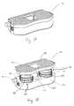
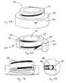
- FIG. 1Ais perspective view of a device employing a coaxial screw gear sleeve mechanism according to an embodiment of the present invention in a collapsed configuration.
- FIG. 1Bis a perspective view of the device of FIG. 1A in an expanded configuration.
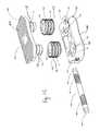
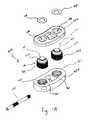
- FIG. 1Cis an exploded view of the device of FIG. 1A .
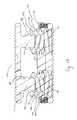
- FIG. 1Dis a partial sectional view of the device of FIG. 1A .
- FIG. 2Ais a partial side view of a coaxial screw gear sleeve mechanism according to an embodiment of the present invention.
- FIG. 2Bis a partial side view of the coaxial screw gear sleeve mechanism of FIG. 2A .
- FIG. 3Ais a partial side view of a coaxial screw gear sleeve mechanism according to an embodiment of the present invention.
- FIG. 3Bis a partial side view of the coaxial screw gear sleeve mechanism of FIG. 3A .
- FIG. 4Ais a partial top view of a coaxial screw gear sleeve mechanism according to an embodiment of the present invention.
- FIG. 4Bis a partial top view of the coaxial screw gear sleeve mechanism of FIG. 4A .
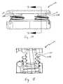
- FIG. 5Ais an end view of a device employing a coaxial screw gear sleeve mechanism according to an embodiment of the present invention.
- FIG. 5Bis a cross-sectional end view of the device of FIG. 5A taken looking into the page.
- FIG. 6Ais a front view of a device employing a coaxial screw gear sleeve mechanism according to an embodiment of the present invention.
- FIG. 6Bis a cross-sectional view of the device of FIG. 6A taken along the lines 6 B- 6 B.
- FIG. 7Ais a front view of a device employing a coaxial screw gear sleeve mechanism according to an embodiment of the present invention.
- FIG. 7Bis a cross-sectional view of the device of FIG. 7A taken along the lines 7 B- 7 B.
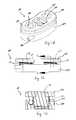
- FIG. 8Ais an exploded view of a device employing a coaxial screw gear sleeve mechanism according to an embodiment of the present invention.
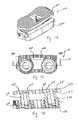
- FIG. 8Bis a perspective view of the device of FIG. 8A .
- FIG. 8Cis a front view of the device of FIG. 8A .
- FIG. 8Dis a cross-sectional view of the device of FIG. 8A taken along the lines 8 D- 8 D in FIG. 8C .
- FIG. 9Ais an exploded view of a device employing a coaxial screw gear sleeve mechanism according to an embodiment of the present invention.
- FIG. 9Bis a perspective view of the device of FIG. 9A .
- FIG. 9Cis a bottom view of the device of FIG. 9A .
- FIG. 9Dis a cross-sectional view of the device of FIG. 9A taken along the lines 9 D- 9 D in FIG. 9C .
- FIG. 10Ais a perspective view of a device employing a coaxial screw gear sleeve mechanism according to an embodiment of the present invention.
- FIG. 10Bis a front view of the device of FIG. 10A .
- FIG. 10Cis a cross-sectional view of the device of FIG. 10A taken along the lines 10 C- 10 C in FIG. 10B .
- FIG. 10Dis a cross-sectional view of the device of FIG. 10A taken along the lines 10 D- 10 D in FIG. 10B .
- FIG. 11Ais a perspective view of a device employing a coaxial screw gear sleeve mechanism according to an embodiment of the present invention.
- FIG. 11Bis a side view of the device of FIG. 11A .
- FIG. 12Ais a perspective view of a device employing a coaxial screw gear sleeve mechanism according to an embodiment of the present invention.
- FIG. 12Bis a side view of the device of FIG. 12A .
- FIG. 13Ais a perspective view of a device employing a coaxial screw gear sleeve mechanism according to an embodiment of the present invention.
- FIG. 13Bis a side view of the device of FIG. 13A .
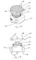
- FIG. 14Ais a perspective view of an expandable device employing a coaxial screw gear sleeve mechanism according to an embodiment of the present invention.
- FIG. 14Bis a partial cutaway view of the device of FIG. 14A .
- FIG. 15Ais a perspective view of a expandable device employing a coaxial screw gear sleeve mechanism according to an embodiment of the present invention.
- FIG. 15Bis a partial view of the device of FIG. 15A .
- FIG. 15Cis a partial view of the device of FIG. 15A .
- FIG. 15Dis a partial view of the device of FIG. 15A .
- FIGS. 1A-1Cthere can be seen a device 100 that utilizes a pair of coaxial screw gear sleeve mechanisms 101 according to an embodiment of the present invention.
- FIG. 1Ashows the device 100 and coaxial screw gear sleeve mechanisms 101 in a fully compressed configuration
- FIG. 1Bshows a fully expanded configuration
- FIG. 1Cshows an exploded view of the device 100 .
- Device 100includes a first member 110 having an outer surface 102 and a second member 150 having an outer surface 104 .
- Coaxial screw gear sleeve mechanisms 101include respective threaded post members 111 , 112 extending from first member 110 and a pair of threaded geared sleeves 120 , 130 configured to surround the post members 111 , 112 .
- Threaded post members 111 , 112can have threads 113 , 114 defined on an exterior surface thereof.
- Threaded geared sleeves 120 , 130can have both interior threads 122 , 132 configured to interface with the threads 113 , 114 of threaded post members 111 , 112 and exterior threads 121 , 131 .
- both the exterior 121 and interior 122 threads of one of the sleeves 120are of an opposite hand to the threads 131 , 132 of the other sleeve 130 .
- External threads 121 , 131 of sleeves 120 , 130can have gear teeth 124 , 134 cut into the thread.
- the gear teeth 124 , 134are not cut down to the root, or minor diameter, of the threads 121 , 131 in order to maximize the strength of the threads.
- threaded geared sleeves 120 , 130can fit within sleeve openings 161 , 162 in second member 150 .
- Openings 161 , 162can include threaded portions 151 , 152 that mesh with exterior threads 121 , 131 of threaded geared sleeves 120 , 130 .
- threaded geared sleeves 120 , 130can be substantially solid.
- threaded geared sleevescan include one or more slots through the sleeve for mass reduction and material savings.
- the coaxial screw gear sleeve mechanisms 101can be actuated, and the device 100 therefore expanded, with the aid of a worm 140 that extends through a worm aperture 154 in the device 100 .
- the worm 140can have first 142 and second 141 opposing threaded sections configured to interface with the exterior threads having gear teeth 124 , 134 of threaded geared sleeves 120 , 130 through a pair of apertures 157 , 158 in threaded portions 151 , 152 of sleeve openings 161 , 162 .
- the worm 140can include a hex 143 , 144 at each end of the worm 140 that allows it to be driven by an external device.
- a partial sectional view of a pair of coaxial screw gear sleeve mechanisms 101 in use with a device 100 in FIG. 1Dhelps illustrate how a device can employ multiple coaxial screw gear sleeve mechanisms as telescoping mechanisms utilizing the threaded post members 111 , 112 , threaded geared sleeves 120 , 130 and the worm 140 to expand the first member 110 and second member 150 relative to each other.
- first threaded section 142 of worm 140pulls the gear teeth 134 of threaded geared sleeve 130 towards the hex head 144 .
- the threads for like components for each deviceare opposite handed, the threads 142 on one side of the worm 140 will be pulling the gear teeth 134 of the threaded geared sleeve 130 while the threads 141 on the other side of the worm 140 will be pushing the gear teeth 124 on the other sleeve 120 , or vice versa depending on the direction of rotation of the worm 140 .
- These opposing forces applied to the worm 140 by the threaded geared sleeves 120 , 130are carried in either tension or compression by the worm 140 .
- Alternative drive mechanisms to worm drive for actuating coaxial screw gear sleeve mechanismsinclude piezoelectric actuators and any momentum imparting collision mechanism or configuration.
- FIGS. 2A and 2Ba preferred fit of gear teeth 124 , 134 of threaded geared sleeves 120 , 130 with a cooperating thread such as internal threaded portions, 151 , 152 of second member 150 is shown.
- the gear teeth 124 , 134are thrust towards the internal threads 151 , 152 of the second member 150 by the worm, the load between the gear teeth 124 , 134 and threads 151 , 152 is balanced by the bearing surfaces 163 , 164 between the components, which results in the ability of the device 100 to expand under or lift a substantial load.
- This fit between the gear teeth 124 , 134 and the internal threads 151 , 152can be contrast with the fit shown in FIGS.
- threads depicted in the Figuresare all screw threads in the form of projecting helical ribs
- threadfor the purposes of the present invention can also refer to any other mechanism that translates rotational force into translational or longitudinal movement.
- threadscan be comprised of a recirculating or spiral arrangement of bearings or any other low friction arrangement, such as cooperating magnets.
- the height of a device 100 utilizing coaxial gear sleeve mechanisms 101 between the bearing surfaces 102 , 104 in the fully compressed configurationis 6.5 millimeters and the maximum fully expanded height is 12 millimeters, thus providing a very large amount of expansion relative to the initial height of the device.
- the maximum heightis defined by the largest height at which the device can meet the dynamic compressive, shear, and torsional requirements for the given use of the device. Variables that determine this height include the width of the threaded geared sleeves, which is limited by the desired width of the device, and the material from which the device is made. With regard to the material for the device, materials with higher fatigue performance allow the maximum height of the device to be taller even with a narrower width.
- coaxial gear sleeve mechanisms 101do not require a locking mechanism to maintain the desired height, even under loading conditions. This is because, when driven backwards, the mechanism exhibits a very high gear ratio which causes even the slightest friction in the system to overwhelm any amount of compression, torsion, or shear loading that might be applied to the device. In dynamic testing in shear, torsion, and compression, the maximum amount by which the height of one embodiment of the device that had a maximum expansion of 5.5 millimeters changed was by approximately 0.01 millimeter. The device 100 , because height can be maintained at any point along the threaded geared sleeves, therefore also exhibits very high resolution height control, on the order of 1 micrometer.
- the external threads 121 , 131 and gear teeth 124 , 134 on the threaded geared sleeves 120 , 130can be substantially trapezoidal in shape.
- the threadis a trapezoidal 8 millimeter by 1.5 millimeter metric thread.
- a trapezoidal designenables a relatively large gear tooth size and, accordingly, a larger area over which the expansion or lifting loading is distributed.
- multiple gear teeth 124 , 134 on the threaded geared sleeves 120 , 130can be engaged by the worm 140 at the same time along the pressure angle ANG, as shown in FIGS. 4A and 4B . Distributing the expansion load over multiple teeth of the sleeves 120 , 130 and the worm 140 is critical to achieve the minimum device size while providing a maximum amount of expansion or lift and load capacity.
- the coaxial gear sleeve mechanisms 101can be used with a device 100 having a strengthened second member 150 as shown in FIGS. 5A and 5B .
- Thiscan be done by lowering the worm aperture 154 , and therefore the worm 140 , such that when the device 100 is expanded to its full height, the worm 140 engages a full gear tooth 134 A on the threaded geared sleeve 130 closest to the bottom 136 of the threaded geared sleeve 130 .
- Thisallows a top surface 166 of the second member 150 to be lowered, which allows the first member 110 to be thicker, and therefore stronger, while maintaining the same initial height.
- thisallows the material 168 between the top surface 166 of the second member 150 and the worm aperture 154 to be made thicker.
- a further advantage of this configurationis that at least one full internal thread 152 A of the second member 150 is in engagement with the threaded geared sleeve 134 when the device is fully expanded. In such a configuration, an additional thickness 167 can be added to the side of second member 150 opposite of the worm aperture 154 to what was previously described as the top surface 166 A of that side of the second member 150 . This allows for a full internal thread 152 B to engage the threaded geared sleeve 130 on the side opposite of internal thread 152 A.
- FIGS. 6A and 6Bdepict another embodiment of the present invention where in threaded posts 111 , 112 employ a buttress thread 113 A, 114 A (compare threads 113 A in FIG. 6B to threads 113 , 114 in FIG. 1D ).
- a buttress thread configurationresults in the load bearing thread face being perpendicular to the screw axis of the post 111 , 112 , which increases the axial strength of the coaxial screw gear sleeve mechanisms.
- FIGS. 7A and 7Bdepict a further embodiment that utilizes a standard 60 degree thread 113 B, 114 B on threaded posts 111 , 112 . 60 degree threads are considered industry standard and can therefore be created with common machining practices. This can result in a device that can be more quickly and inexpensively produced.
- another expandable device 400includes a pair of coaxial screw gear sleeve mechanisms 401 comprising threaded geared posts 423 extending between first member 410 and second member 450 rather than the separate threaded geared sleeves 120 , 130 and threaded posts 111 , 112 described previously.
- Threaded geared posts 423each include a threaded geared portion 421 and a post portion 411 .
- Threaded geared portions 421fit within openings 461 in second member 450 and interface with worm 440 and internal threads 451 to cause the device 400 to expand or lift.
- Post portions 411fit within openings 416 in first member 410 and can be attached to washers 418 .
- Washers 418keep the first member 410 in place relative to the threaded geared posts 423 as the threaded geared posts 423 rotate freely independent of the first member 410 when the device 400 is actuated.
- the expansion between the first member 410 and the second member 450is caused by the thicker threaded geared portions 421 while the post portions 411 remain within the openings 416 in first member 410 . This leads to a device 400 having increased axial strength.
- FIGS. 9A-9Ddepict a further embodiment of an expandable device 500 utilizing coaxial screw gear sleeve mechanisms 501 that allows for differential adjustment of the threaded geared sleeves 520 .
- Threaded posts 511can each include an arched portion 515 that corresponds to an arched recess 517 in first member 510 .
- the arched interface between the threaded posts 511 and the first member 510 created by the corresponding arched portions 515 and arched recesses 517allows the first member 510 to rotate and become angled relative to the second member 550 .
- a pin joint utilizing a pivot pin 572can be used to keep one interface between the first member 510 and a threaded post 511 stationary, while the other interface is allowed to slide due to the arched surfaces.
- Worm 540can be a two-part worm including a first portion 546 having a first threaded section 543 and second portion 548 having a second threaded section 544 that fits onto a post 547 of first portion 546 .
- the two portions 546 , 548can therefore be rotated independently of each other, with each driving a separate threaded geared sleeve 520 . Because each threaded geared sleeve 520 can be engaged separately, they can be expanded by different amounts, resulting in an angled first member 510 as shown most clearly in FIG. 9D .
- the arched recesses 517 in the first member 550 and arched surfaces 515 of the posts 511could be replaced with flexural joints or ball or cylinder and socket joints.
- FIGS. 10A-10DAn expandable device 600 according to another embodiment of the present invention is depicted in FIGS. 10A-10D .
- Device 600uses three coaxial screw gear sleeve mechanisms 601 , each having a threaded geared sleeve 620 and a threaded post 621 , between first member 610 and second member 650 .
- the worm drive 640is rotated and it engages one of the threaded geared sleeves 620 , causing it to rotate.
- the first threaded geared sleeve 620rotates, it engages the other two threaded geared sleeves 620 , causing them to rotate and the device 600 to expand.
- the rotation of the threaded geared sleeves 620also causes the threaded posts 621 to expand, as described previously.
- Use of three coaxial screw gear sleeve mechanismsprovides for a device having increased strength in the axial direction and a broader surface area for supporting loads.
- each of the three expansion mechanismscould be actuated independently to adjust the surface of the device in additional degrees of freedom.
- FIGS. 11A and 11Bdepict a device 700 that employs only a single coaxial screw gear mechanism 701 having a threaded geared sleeve 720 and a threaded post 721 for expanding first member 710 relative to second member 750 with worm 740 .
- Device 700also can include first 774 and second 776 telescoping support elements. Telescoping support elements 774 , 776 serve to maintain the relative rotational positioning of the first member 710 with respect to the second member 750 , enabling the threaded geared sleeve 720 to rotate with respect to both the first member 710 and second member 750 to expand the device 700 .
- FIGS. 13A and 13Bdepict a further variation of device 700 that utilizes a plurality of spikes 778 extending from the first member 710 and second member 750 to rotationally constrain the first member 710 and second member 750 .
- the spikes 778contact adjacent surfaces and can fix themselves to those surfaces to prevent the first member 710 and second member 750 from rotating relative to each other.
- FIGS. 13A and 13Bdepict a further embodiment is depicted in FIGS. 13A and 13B .
- This embodimentincludes a coaxial screw gear sleeve mechanism having only a threaded geared sleeve 720 between first member 710 and second member 750 and allows the first member 710 to rotate with the sleeve 720 as the device 700 is expanded via rotation of the worm 740 .
- first member 710could be rotationally free with respect to the threaded geared sleeve 720 so that the first member 710 is allowed to engage and not rotate against an adjacent surface.
- FIGS. 14A and 14Bdepict an expandable device 800 including an enveloping coaxial screw gear sleeve with recirculating bearings according to another embodiment of the present invention.
- Device 800includes a post 810 , an enveloping coaxial screw gear sleeve 820 , a worm 830 and a housing 840 .
- Post 810includes a smooth outer surface 812 and a machined helical raceway 811 for bearings 813 .
- a helical raceway(not shown) is also machined into inner surface of enveloping coaxial screw gear sleeve 820 that is complementary to helical raceway 811 for accommodating bearings 813 .
- the inner surface of coaxial screw gear sleeve 820also includes a machined tunnel for recirculation of bearings 813 as the post 810 moves with respect to the sleeve 820 .
- the recirculating bearingsare depicted as bearings 814 in FIG. 14B .
- the outer surface of the enveloping coaxial screw gear sleevealso includes a helical raceway 821 for recirculating bearings 814 and an enveloping screw gear 822 .
- the worm 830has a helical thread configured to engage the enveloping screw gear 822 of the sleeve 820 .
- the inner surface of the housing 840has a helical raceway (not shown) that cooperates with helical raceway 821 to retain bearings 814 and a tunnel for recirculating bearings 814 as the coaxial screw gear sleeve 820 moves with respect to the housing 840 .
- the worm 830is rotated clockwise to engage the enveloping screw gear 822 to rotate and translate the enveloping coaxial screw gear sleeve 820 out of the housing 840 .
- Bearings 813 , 814enable the rotation of the enveloping coaxial screw gear sleeve 820 with very little friction, enabling the device 800 to exhibit a very high mechanical advantage and displacement control with very high resolution.
- the use of the enveloping screw gear 822enables the interface between the worm 830 and the enveloping coaxial screw gear sleeve 820 to carry substantially higher loading.
- Device 900includes an enveloping coaxial screw gear 910 , a housing 920 and a worm 930 .
- the outer surface of enveloping coaxial screw gear sleeve 910includes a helical groove having a series of enveloping coaxial screw gear teeth 914 .
- the helical groovecan cooperate with an internal thread 921 on the inner surface 922 of housing 920 to allow the device 900 to carry an axial load.
- the gear teeth 914can be machined directly into the outer surface of the enveloping coaxial screw gear sleeve 910 .
- the outer surface of the enveloping coaxial screw gear sleeve 910can be a smooth machined surface that acts like a bearing surface when configured with a similar smooth bearing surface on the inner surface 922 of housing 920 to enable the device 900 to carry a lateral load.
- the coaxial screw gear sleeve 920could have recirculating bearings both on the inside and the outside of the sleeve and the recirculation tunnel could be between the inside and the outside of the sleeve, both facilitating assembly and manufacturing.
- the worm 930is rotated to engage the enveloping coaxial screw gear teeth 914 to rotate and translate the enveloping coaxial screw gear sleeve 910 with respect to the housing 920 .
- the inner surface 910 and center bore 912can be configured to contain a post similar to the post 910 described in FIGS. 14A and 14B to compound the expansion or lift of the device.
- no thread 921is present on the inner surface 922 of housing 920 , so the helical groove and/or gear teeth 914 of the enveloping coxial screw gear sleeve 910 cause the sleeve 910 to translate with respect to the housing 930 as the sleeve 910 rotates.
- the worm 930would carry any axial load, unassisted by an inclined interface between the enveloping coaxial screw gear sleeve 910 and the housing 920 .
- Coaxial screw gear sleeve mechanisms as described hereincan be made out of any material, including metals, plastics and ceramics.
- coaxial screw gear sleeve mechanisms as described hereincan be made of titanium.
- mechanismscan be made from cobalt chrome, MP35N, PEEK, stainless steel, or carbon fiber.
- Coaxial screw gear sleeve mechanismscan be manufactured in various ways.
- thread millingcan be implemented to manufacture the various threads in device.
- Wire EDMcan be utilized to manufacture some or all of the holes and openings in the device.
- Assembly jigs and post processing stepscan also be utilized to allow the device to be manufactured to exacting standards.
Landscapes
- Health & Medical Sciences (AREA)
- Engineering & Computer Science (AREA)
- Orthopedic Medicine & Surgery (AREA)
- Biomedical Technology (AREA)
- Neurology (AREA)
- Life Sciences & Earth Sciences (AREA)
- Transplantation (AREA)
- Animal Behavior & Ethology (AREA)
- Heart & Thoracic Surgery (AREA)
- General Health & Medical Sciences (AREA)
- Public Health (AREA)
- Veterinary Medicine (AREA)
- Vascular Medicine (AREA)
- Cardiology (AREA)
- Oral & Maxillofacial Surgery (AREA)
- General Engineering & Computer Science (AREA)
- Surgery (AREA)
- Mechanical Engineering (AREA)
- Physical Education & Sports Medicine (AREA)
- Molecular Biology (AREA)
- Medical Informatics (AREA)
- Nuclear Medicine, Radiotherapy & Molecular Imaging (AREA)
- Prostheses (AREA)
- Surgical Instruments (AREA)
- Transmission Devices (AREA)
- Gear Transmission (AREA)
Abstract
Description
Claims (16)
Priority Applications (3)
| Application Number | Priority Date | Filing Date | Title |
|---|---|---|---|
| US12/841,869US9358125B2 (en) | 2009-07-22 | 2010-07-22 | Coaxial screw gear sleeve mechanism |
| US15/174,454US10117757B2 (en) | 2009-07-22 | 2016-06-06 | Coaxial screw gear sleeve mechanism |
| US16/180,448US11026804B2 (en) | 2009-07-22 | 2018-11-05 | Coaxial screw gear sleeve mechanism |
Applications Claiming Priority (3)
| Application Number | Priority Date | Filing Date | Title |
|---|---|---|---|
| US27154809P | 2009-07-22 | 2009-07-22 | |
| US36513110P | 2010-07-16 | 2010-07-16 | |
| US12/841,869US9358125B2 (en) | 2009-07-22 | 2010-07-22 | Coaxial screw gear sleeve mechanism |
Related Child Applications (1)
| Application Number | Title | Priority Date | Filing Date |
|---|---|---|---|
| US15/174,454ContinuationUS10117757B2 (en) | 2009-07-22 | 2016-06-06 | Coaxial screw gear sleeve mechanism |
Publications (2)
| Publication Number | Publication Date |
|---|---|
| US20110138948A1 US20110138948A1 (en) | 2011-06-16 |
| US9358125B2true US9358125B2 (en) | 2016-06-07 |
Family
ID=43499660
Family Applications (9)
| Application Number | Title | Priority Date | Filing Date |
|---|---|---|---|
| US12/841,869Active2033-12-30US9358125B2 (en) | 2009-07-22 | 2010-07-22 | Coaxial screw gear sleeve mechanism |
| US12/841,465ActiveUS8303663B2 (en) | 2009-07-22 | 2010-07-22 | Methods and apparatuses for vertebral body distraction and fusion employing a coaxial screw gear sleeve mechanism |
| US13/591,463ActiveUS8771360B2 (en) | 2009-07-22 | 2012-08-22 | Methods and apparatuses for vertebral body distraction and fusion employing a coaxial screw gear sleeve mechanism |
| US14/318,196ActiveUS9474626B2 (en) | 2009-07-22 | 2014-06-27 | Methods and apparatuses for vertebral body distraction and fusion employing a coaxial screw gear sleeve mechanism |
| US15/174,454Active2030-11-02US10117757B2 (en) | 2009-07-22 | 2016-06-06 | Coaxial screw gear sleeve mechanism |
| US15/332,066ActiveUS10369008B2 (en) | 2009-07-22 | 2016-10-24 | Medical device employing a coaxial screw gear sleeve mechanism |
| US16/180,448Active2031-04-26US11026804B2 (en) | 2009-07-22 | 2018-11-05 | Coaxial screw gear sleeve mechanism |
| US16/529,897Active2032-04-18US11612496B2 (en) | 2009-07-22 | 2019-08-02 | Medical device employing a coaxial screw gear sleeve mechanism |
| US18/124,908PendingUS20230320868A1 (en) | 2009-07-22 | 2023-03-22 | Medical Device Employing a Coaxial Screw Gear Sleeve Mechanism |
Family Applications After (8)
| Application Number | Title | Priority Date | Filing Date |
|---|---|---|---|
| US12/841,465ActiveUS8303663B2 (en) | 2009-07-22 | 2010-07-22 | Methods and apparatuses for vertebral body distraction and fusion employing a coaxial screw gear sleeve mechanism |
| US13/591,463ActiveUS8771360B2 (en) | 2009-07-22 | 2012-08-22 | Methods and apparatuses for vertebral body distraction and fusion employing a coaxial screw gear sleeve mechanism |
| US14/318,196ActiveUS9474626B2 (en) | 2009-07-22 | 2014-06-27 | Methods and apparatuses for vertebral body distraction and fusion employing a coaxial screw gear sleeve mechanism |
| US15/174,454Active2030-11-02US10117757B2 (en) | 2009-07-22 | 2016-06-06 | Coaxial screw gear sleeve mechanism |
| US15/332,066ActiveUS10369008B2 (en) | 2009-07-22 | 2016-10-24 | Medical device employing a coaxial screw gear sleeve mechanism |
| US16/180,448Active2031-04-26US11026804B2 (en) | 2009-07-22 | 2018-11-05 | Coaxial screw gear sleeve mechanism |
| US16/529,897Active2032-04-18US11612496B2 (en) | 2009-07-22 | 2019-08-02 | Medical device employing a coaxial screw gear sleeve mechanism |
| US18/124,908PendingUS20230320868A1 (en) | 2009-07-22 | 2023-03-22 | Medical Device Employing a Coaxial Screw Gear Sleeve Mechanism |
Country Status (9)
| Country | Link |
|---|---|
| US (9) | US9358125B2 (en) |
| EP (2) | EP2456396B1 (en) |
| JP (1) | JP5656997B2 (en) |
| CN (1) | CN102625682B (en) |
| CA (1) | CA2768867C (en) |
| DK (1) | DK2456396T3 (en) |
| ES (2) | ES2653567T3 (en) |
| IN (1) | IN2012DN00952A (en) |
| WO (2) | WO2011011626A2 (en) |
Cited By (77)
| Publication number | Priority date | Publication date | Assignee | Title |
|---|---|---|---|---|
| US9668879B2 (en) | 2014-04-01 | 2017-06-06 | Ex Technology, Llc | Expandable intervertebral cage |
| US9750618B1 (en) | 2016-11-29 | 2017-09-05 | Amendia, Inc. | Intervertebral implant device with independent distal-proximal expansion |
| US9867717B2 (en) | 2009-03-19 | 2018-01-16 | Ex Technology, Llc | Stable device for intervertebral distraction and fusion |
| US9974662B2 (en) | 2016-06-29 | 2018-05-22 | Globus Medical, Inc. | Expandable fusion device and method of installation thereof |
| US10052215B2 (en) | 2016-06-29 | 2018-08-21 | Globus Medical, Inc. | Expandable fusion device and method of installation thereof |
| US10060469B2 (en) | 2008-12-31 | 2018-08-28 | Ex Technology, Llc | Flexible joint arrangement incorporating flexure members |
| US10219914B2 (en) | 2015-11-10 | 2019-03-05 | Globus Medical, Inc. | Stabilized expandable intervertebral spacer |
| WO2019140240A1 (en) | 2018-01-11 | 2019-07-18 | K2M, Inc. | Implants and instruments with flexible features |
| US10369008B2 (en) | 2009-07-22 | 2019-08-06 | Spinex Tec Llc | Medical device employing a coaxial screw gear sleeve mechanism |
| US10548743B2 (en) | 2014-12-16 | 2020-02-04 | Globus Medical, Inc. | Expandable fusion devices and methods of installation thereof |
| US10864086B2 (en) | 2010-02-24 | 2020-12-15 | Globus Medical, Inc. | Expandable intervertebral spacer and method of posterior insertion thereof |
| US11191650B2 (en) | 2020-02-03 | 2021-12-07 | Globus Medical Inc. | Expandable fusions devices, instruments, and methods thereof |
| US11234835B2 (en) | 2019-03-05 | 2022-02-01 | Octagon Spine Llc | Transversely expandable minimally invasive intervertebral cage |
| US11298240B2 (en) | 2020-06-16 | 2022-04-12 | Globus Medical, Inc. | Expanding intervertebral implants |
| US11337829B2 (en) | 2018-03-09 | 2022-05-24 | K2M, Inc. | Devices for inserting and expanding spinal implants |
| US11357640B2 (en) | 2020-07-08 | 2022-06-14 | Globus Medical Inc. | Expandable interbody fusions devices |
| WO2022133130A1 (en)* | 2020-12-16 | 2022-06-23 | Amplify Surgical, Inc. | Anchored intervertebral implants |
| US11491020B2 (en) | 2020-07-09 | 2022-11-08 | Globus Medical, Inc. | Articulating and expandable interbody fusions devices |
| US11497622B2 (en) | 2019-03-05 | 2022-11-15 | Ex Technology, Llc | Transversely expandable minimally invasive intervertebral cage and insertion and extraction device |
| US11628068B2 (en) | 2013-03-15 | 2023-04-18 | Globus Medical, Inc. | Expandable intervertebral implant |
| US11666457B2 (en) | 2009-10-15 | 2023-06-06 | Globus Medical Inc. | Expandable fusion device and method of installation thereof |
| US11690733B2 (en) | 2009-10-15 | 2023-07-04 | Globus Medical Inc. | Expandable fusion device and method of installation thereof |
| US11701236B2 (en) | 2013-03-01 | 2023-07-18 | Globus Medical, Inc. | Articulating expandable intervertebral implant |
| US11717420B2 (en) | 2011-09-30 | 2023-08-08 | Globus Medical, Inc. | Expandable fusion device and method of installation thereof |
| US11723780B2 (en) | 2015-07-17 | 2023-08-15 | Globus Medical, Inc. | Intervertebral spacer and plate |
| US11744714B2 (en) | 2015-05-21 | 2023-09-05 | Globus Medical Inc. | Device and method for deployment of an anchoring device for intervertebral spinal fusion |
| US11759328B2 (en) | 2019-09-06 | 2023-09-19 | Globus Medical Inc. | Expandable motion preservation spacer |
| US11766340B2 (en) | 2013-03-01 | 2023-09-26 | Globus Medical, Inc. | Articulating expandable intervertebral implant |
| US11771564B2 (en) | 2013-02-15 | 2023-10-03 | Globus Medical Inc. | Articulating and expandable vertebral implant |
| US11801148B2 (en) | 2010-06-25 | 2023-10-31 | Globus Medical, Inc. | Expandable fusion device and method of installation thereof |
| US11813175B2 (en) | 2012-12-31 | 2023-11-14 | Globus Medical, Inc. | Spinous process fixation system and methods thereof |
| US11826263B2 (en) | 2010-09-03 | 2023-11-28 | Globus Medical, Inc. | Expandable fusion device and method of installation thereof |
| US11844703B2 (en) | 2010-06-25 | 2023-12-19 | Globus Medical Inc. | Expandable fusion device and method of installation thereof |
| US11857437B2 (en) | 2010-09-03 | 2024-01-02 | Globus Medical, Inc. | Expandable fusion device and method of installation thereof |
| US11883080B1 (en) | 2022-07-13 | 2024-01-30 | Globus Medical, Inc | Reverse dynamization implants |
| US11890203B2 (en) | 2009-10-15 | 2024-02-06 | Globus Medical, Inc | Expandable fusion device and method of installation thereof |
| US11896499B2 (en) | 2021-12-02 | 2024-02-13 | Globus Medical, Inc | Expandable fusion device with integrated deployable retention spikes |
| US11896496B2 (en) | 2015-05-21 | 2024-02-13 | Globus Medical, Inc. | Device and method for deployment of an anchoring device for intervertebral spinal fusion |
| US11896492B2 (en) | 2013-03-15 | 2024-02-13 | Globus Medical, Inc. | Expandable intervertebral implant |
| US11896493B2 (en) | 2015-12-16 | 2024-02-13 | Globus Medical, Inc | Expandable intervertebral spacer |
| US11903844B2 (en) | 2015-05-21 | 2024-02-20 | Globus Medical, Inc. | Device and method for deployment of an anchoring device for intervertebral spinal fusion |
| US11911291B2 (en) | 2015-09-02 | 2024-02-27 | Globus Medical, Inc. | Implantable systems, devices and related methods |
| US11925565B2 (en) | 2014-02-07 | 2024-03-12 | Globus Medical Inc. | Variable lordosis spacer and related methods of use |
| US11944551B2 (en) | 2012-12-11 | 2024-04-02 | Globus Medical, Inc. | Expandable vertebral implant |
| US11998455B2 (en) | 2016-09-14 | 2024-06-04 | Globus Medical, Inc. | Systems and methods for expandable corpectomy spacer implantation |
| US12011365B2 (en) | 2022-07-18 | 2024-06-18 | Octagon Spine Llc | Transversely expandable minimally invasive inter vertebral cage |
| US12011364B2 (en) | 2022-06-15 | 2024-06-18 | Globus Medical, Inc | Expandable footprint implant |
| US12011368B2 (en) | 2015-05-14 | 2024-06-18 | Globus Medical, Inc | Expandable inter vertebral implants and methods of installation thereof |
| US12011369B2 (en) | 2010-09-03 | 2024-06-18 | Globus Medical Inc. | Expandable interspinous process fixation device |
| US12016785B2 (en) | 2015-09-02 | 2024-06-25 | Globus Medical Inc | Expandable intervertebral fusion devices and methods of installation thereof |
| US12029658B2 (en) | 2020-07-09 | 2024-07-09 | Globus Medical, Inc. | Intradiscal fixation systems |
| US12029659B2 (en) | 2015-12-15 | 2024-07-09 | Globus Medical, Inc. | Stabilized intervertebral spacer |
| US12059358B2 (en) | 2010-09-03 | 2024-08-13 | Globus Medical Inc. | Expandable fusion device and method of installation thereof |
| US12059179B2 (en) | 2016-02-02 | 2024-08-13 | Globus Medical, Inc. | Expandable spinal fixation system |
| US12097126B2 (en) | 2021-09-29 | 2024-09-24 | Ex Technology, Llc | Expandable intervertebral cage |
| US12138177B2 (en) | 2017-11-09 | 2024-11-12 | Globus Medical Inc. | Expandable intervertebral implant |
| US12161563B2 (en) | 2016-09-14 | 2024-12-10 | Globus Medical, Inc. | Systems and methods for expandable corpectomy spacer implantation |
| US12167970B2 (en) | 2013-03-15 | 2024-12-17 | Globus Medical, Inc. | Expandable inter vertebral implant |
| US12213890B2 (en) | 2015-07-17 | 2025-02-04 | Globus Medical, Inc. | Intervertebral spacer and plate |
| US12220323B2 (en) | 2019-07-18 | 2025-02-11 | Globus Medical, Inc. | Expanding intervertebral implants |
| US12232976B2 (en) | 2010-09-03 | 2025-02-25 | Globus Medical, Inc. | Expandable fusion device and method of installation thereof |
| US12251321B2 (en) | 2013-02-25 | 2025-03-18 | Globus Medical, Inc. | Expandable intervertebral implant |
| US12251317B2 (en) | 2010-09-03 | 2025-03-18 | Globus Medical, Inc. | Expandable fusion device and method of installation thereof |
| US12263092B2 (en) | 2019-12-20 | 2025-04-01 | Globus Medical Inc. | Stabilizing vertebrae with articulating implants |
| US12279971B2 (en) | 2010-04-12 | 2025-04-22 | Globus Medical, Inc. | Angling inserter tool for expandable vertebral implant |
| US12324745B2 (en) | 2020-01-23 | 2025-06-10 | Globus Medical Inc. | Articulating expandable interbody fusions devices |
| US12324748B2 (en) | 2021-12-02 | 2025-06-10 | Globus Medical, Inc. | Expandable fusion device with integrated deployable retention spikes |
| US12350170B2 (en) | 2013-03-15 | 2025-07-08 | Globus Medical, Inc. | Expandable intervertebral implant |
| US12370058B2 (en) | 2022-04-05 | 2025-07-29 | Spine Wave, Inc. | Belt driven expandable interbody fusion device |
| US12376967B2 (en) | 2010-09-03 | 2025-08-05 | Globus Medical, Inc. | Expandable fusion device and method of installation thereof |
| US12390339B2 (en) | 2012-05-30 | 2025-08-19 | Globus Medical Inc. | Expandable interbody spacer |
| US12390341B2 (en) | 2014-02-07 | 2025-08-19 | Globus Medical, Inc. | Variable lordosis spacer and related methods of use |
| US12396866B2 (en) | 2023-09-27 | 2025-08-26 | Globus Medical, Inc. | Expandable anterior lumbar implants |
| US12396867B2 (en) | 2023-03-21 | 2025-08-26 | Globus Medical, Inc. | Expandable footprint implant |
| US12427038B2 (en) | 2023-06-27 | 2025-09-30 | Globus Medical Inc. | Expandable intervertebral interbody implants |
| US12427037B2 (en) | 2010-09-03 | 2025-09-30 | Globus Medical, Inc. | Expandable fusion device and method of installation thereof |
| US12440348B2 (en) | 2024-05-10 | 2025-10-14 | Globus Medical Inc. | Expandable fusion device and method of installation thereof |
Families Citing this family (273)
| Publication number | Priority date | Publication date | Assignee | Title |
|---|---|---|---|---|
| FR2897259B1 (en) | 2006-02-15 | 2008-05-09 | Ldr Medical Soc Par Actions Si | INTERSOMATIC TRANSFORAMINAL CAGE WITH INTERBREBAL FUSION GRAFT AND CAGE IMPLANTATION INSTRUMENT |
| US7041309B2 (en) | 2002-06-13 | 2006-05-09 | Neuropro Technologies, Inc. | Spinal fusion using an HMG-CoA reductase inhibitor |
| US6793678B2 (en) | 2002-06-27 | 2004-09-21 | Depuy Acromed, Inc. | Prosthetic intervertebral motion disc having dampening |
| AU2004212942A1 (en) | 2003-02-14 | 2004-09-02 | Depuy Spine, Inc. | In-situ formed intervertebral fusion device |
| US20040267367A1 (en) | 2003-06-30 | 2004-12-30 | Depuy Acromed, Inc | Intervertebral implant with conformable endplate |
| EP2113227B1 (en) | 2004-02-04 | 2015-07-29 | LDR Medical | Intervertebral disc prosthesis |
| US8636802B2 (en) | 2004-03-06 | 2014-01-28 | DePuy Synthes Products, LLC | Dynamized interspinal implant |
| US8597360B2 (en) | 2004-11-03 | 2013-12-03 | Neuropro Technologies, Inc. | Bone fusion device |
| WO2006058221A2 (en) | 2004-11-24 | 2006-06-01 | Abdou Samy M | Devices and methods for inter-vertebral orthopedic device placement |
| US9801733B2 (en)* | 2005-03-31 | 2017-10-31 | Life Spine, Inc. | Expandable spinal interbody and intravertebral body devices |
| FR2891135B1 (en) | 2005-09-23 | 2008-09-12 | Ldr Medical Sarl | INTERVERTEBRAL DISC PROSTHESIS |
| US7854765B2 (en) | 2006-04-20 | 2010-12-21 | Moskowitz Mosheh T | Electronically controlled artificial intervertebral disc with motor assisted actuation systems |
| US9526525B2 (en) | 2006-08-22 | 2016-12-27 | Neuropro Technologies, Inc. | Percutaneous system for dynamic spinal stabilization |
| WO2008070863A2 (en) | 2006-12-07 | 2008-06-12 | Interventional Spine, Inc. | Intervertebral implant |
| FR2916956B1 (en) | 2007-06-08 | 2012-12-14 | Ldr Medical | INTERSOMATIC CAGE, INTERVERTEBRAL PROSTHESIS, ANCHORING DEVICE AND IMPLANTATION INSTRUMENTATION |
| US8900307B2 (en) | 2007-06-26 | 2014-12-02 | DePuy Synthes Products, LLC | Highly lordosed fusion cage |
| EP2237748B1 (en) | 2008-01-17 | 2012-09-05 | Synthes GmbH | An expandable intervertebral implant |
| US8088163B1 (en) | 2008-02-06 | 2012-01-03 | Kleiner Jeffrey B | Tools and methods for spinal fusion |
| US8992620B2 (en) | 2008-12-10 | 2015-03-31 | Coalign Innovations, Inc. | Adjustable distraction cage with linked locking mechanisms |
| US20100145455A1 (en) | 2008-12-10 | 2010-06-10 | Innvotec Surgical, Inc. | Lockable spinal implant |
| US8932355B2 (en) | 2008-02-22 | 2015-01-13 | Coalign Innovations, Inc. | Spinal implant with expandable fixation |
| US12232975B2 (en) | 2008-02-22 | 2025-02-25 | Howmedica Osteonics Corp. | Lockable spinal implant |
| US8267939B2 (en) | 2008-02-28 | 2012-09-18 | Stryker Spine | Tool for implanting expandable intervertebral implant |
| US8936641B2 (en) | 2008-04-05 | 2015-01-20 | DePuy Synthes Products, LLC | Expandable intervertebral implant |
| US20210378834A1 (en) | 2008-05-22 | 2021-12-09 | Spinal Surgical Strategies, Inc., A Nevada Corporation D/B/A Kleiner Device Labs | Spinal fusion cage system with inserter |
| US8366748B2 (en) | 2008-12-05 | 2013-02-05 | Kleiner Jeffrey | Apparatus and method of spinal implant and fusion |
| BRPI0921108A2 (en)* | 2008-12-22 | 2016-02-16 | Synthes Gmbh | expandable vertebral body replacement method and system |
| US9247943B1 (en) | 2009-02-06 | 2016-02-02 | Kleiner Intellectual Property, Llc | Devices and methods for preparing an intervertebral workspace |
| US9526620B2 (en) | 2009-03-30 | 2016-12-27 | DePuy Synthes Products, Inc. | Zero profile spinal fusion cage |
| US9408715B2 (en) | 2009-04-15 | 2016-08-09 | DePuy Synthes Products, Inc. | Arcuate fixation member |
| US8641766B2 (en)* | 2009-04-15 | 2014-02-04 | DePuy Synthes Products, LLC | Arcuate fixation member |
| KR101687435B1 (en) | 2009-07-06 | 2016-12-19 | 신세스 게엠바하 | Expandable fixation assemblies |
| CN105326585B (en)* | 2009-09-17 | 2018-12-11 | Ldr控股公司 | Intervertebral implant with extensible bone anchoring element |
| US10973656B2 (en) | 2009-09-18 | 2021-04-13 | Spinal Surgical Strategies, Inc. | Bone graft delivery system and method for using same |
| US20170238984A1 (en) | 2009-09-18 | 2017-08-24 | Spinal Surgical Strategies, Llc | Bone graft delivery device with positioning handle |
| US10245159B1 (en) | 2009-09-18 | 2019-04-02 | Spinal Surgical Strategies, Llc | Bone graft delivery system and method for using same |
| US9629729B2 (en) | 2009-09-18 | 2017-04-25 | Spinal Surgical Strategies, Llc | Biological delivery system with adaptable fusion cage interface |
| US8906028B2 (en) | 2009-09-18 | 2014-12-09 | Spinal Surgical Strategies, Llc | Bone graft delivery device and method of using the same |
| US9155628B2 (en) | 2009-10-15 | 2015-10-13 | Globus Medical, Inc. | Expandable fusion device and method of installation thereof |
| US10806596B2 (en)* | 2009-10-15 | 2020-10-20 | Globus Medical, Inc. | Expandable fusion device and method installation thereof |
| US10327917B2 (en) | 2009-10-15 | 2019-06-25 | Globus Medical, Inc. | Expandable fusion device and method of installation thereof |
| US9216095B2 (en) | 2009-10-15 | 2015-12-22 | Globus Medical, Inc. | Expandable fusion device and method of installation thereof |
| US8709086B2 (en) | 2009-10-15 | 2014-04-29 | Globus Medical, Inc. | Expandable fusion device and method of installation thereof |
| US8556979B2 (en) | 2009-10-15 | 2013-10-15 | Globus Medical, Inc. | Expandable fusion device and method of installation thereof |
| US11564807B2 (en) | 2009-10-15 | 2023-01-31 | Globus Medical, Inc. | Expandable fusion device and method of installation thereof |
| US8062375B2 (en) | 2009-10-15 | 2011-11-22 | Globus Medical, Inc. | Expandable fusion device and method of installation thereof |
| RU2557692C2 (en)* | 2009-11-10 | 2015-07-27 | Смит Энд Нефью, Инк. | Adjustment of bone compression |
| US8764806B2 (en) | 2009-12-07 | 2014-07-01 | Samy Abdou | Devices and methods for minimally invasive spinal stabilization and instrumentation |
| US9393129B2 (en) | 2009-12-10 | 2016-07-19 | DePuy Synthes Products, Inc. | Bellows-like expandable interbody fusion cage |
| US9599202B2 (en)* | 2009-12-18 | 2017-03-21 | Schaeffler Technologies AG & Co. KG | Internal recirculation insert for a ball screw and ball screw assembly including the insert |
| WO2011080535A1 (en) | 2009-12-31 | 2011-07-07 | Lrd Medical | Anchoring device, intervertebral implant and implantation instrument |
| US8636746B2 (en) | 2009-12-31 | 2014-01-28 | Spinex Tec, Llc | Methods and apparatus for insertion of vertebral body distraction and fusion devices |
| US8353963B2 (en)* | 2010-01-12 | 2013-01-15 | Globus Medical | Expandable spacer and method for use thereof |
| WO2011097315A1 (en) | 2010-02-02 | 2011-08-11 | Azadeh Farin | Spine surgery device |
| EP2547292B1 (en) | 2010-03-16 | 2019-04-24 | Pinnacle Spine Group, LLC | Ntervertebral implants and graft delivery systems |
| US9271842B2 (en)* | 2010-04-12 | 2016-03-01 | Globus Medical, Inc. | Expandable trial assembly for expandable vertebral implant |
| GB201006173D0 (en)* | 2010-04-14 | 2010-06-02 | Depuy Ireland | A distractor |
| US8979860B2 (en) | 2010-06-24 | 2015-03-17 | DePuy Synthes Products. LLC | Enhanced cage insertion device |
| US9907560B2 (en) | 2010-06-24 | 2018-03-06 | DePuy Synthes Products, Inc. | Flexible vertebral body shavers |
| US8623091B2 (en) | 2010-06-29 | 2014-01-07 | DePuy Synthes Products, LLC | Distractible intervertebral implant |
| BR112013002765A2 (en) | 2010-07-15 | 2017-09-19 | Nlt Spine Ltd | deflectable implant, system and methods for implantation |
| US10512550B2 (en) | 2010-09-03 | 2019-12-24 | Globus Medical, Inc. | Expandable interspinous process fixation device |
| US8845732B2 (en) | 2010-09-03 | 2014-09-30 | Globus Medical, Inc. | Expandable fusion device and method of installation thereof |
| US11446162B2 (en) | 2010-09-03 | 2022-09-20 | Globus Medical, Inc. | Expandable fusion device and method of installation thereof |
| US10869768B2 (en) | 2010-09-03 | 2020-12-22 | Globus Medical Inc. | Expandable fusion device and method of installation thereof |
| US11793654B2 (en) | 2010-09-03 | 2023-10-24 | Globus Medical, Inc. | Expandable fusion device and method of installation thereof |
| US10085849B2 (en) | 2010-09-03 | 2018-10-02 | Globus Medical, Inc. | Expandable fusion device and method of installation thereof |
| US9907673B2 (en) | 2010-09-03 | 2018-03-06 | Globus Medical, Inc. | Expandable fusion device and method of installation thereof |
| US8435298B2 (en) | 2010-09-03 | 2013-05-07 | Globus Medical, Inc. | Expandable fusion device and method of installation thereof |
| US9855151B2 (en) | 2010-09-03 | 2018-01-02 | Globus Medical, Inc | Expandable fusion device and method of installation thereof |
| US8491659B2 (en) | 2010-09-03 | 2013-07-23 | Globus Medical, Inc. | Expandable fusion device and method of installation thereof |
| US10709573B2 (en) | 2010-09-03 | 2020-07-14 | Globus Medical Inc. | Expandable fusion device and method of installation thereof |
| US9474625B2 (en) | 2010-09-03 | 2016-10-25 | Globus Medical, Inc | Expandable fusion device and method of installation thereof |
| US10758367B2 (en) | 2010-09-03 | 2020-09-01 | Globus Medical Inc. | Expandable fusion device and method of installation thereof |
| US10779957B2 (en) | 2010-09-03 | 2020-09-22 | Globus Medical, Inc. | Expandable fusion device and method of installation thereof |
| US20120078372A1 (en) | 2010-09-23 | 2012-03-29 | Thomas Gamache | Novel implant inserter having a laterally-extending dovetail engagement feature |
| US9402732B2 (en) | 2010-10-11 | 2016-08-02 | DePuy Synthes Products, Inc. | Expandable interspinous process spacer implant |
| US8377140B2 (en)* | 2011-01-12 | 2013-02-19 | Ebi, Llc | Expandable spinal implant device |
| US8740980B2 (en)* | 2011-01-27 | 2014-06-03 | Warsaw Orthopedic, Inc. | Expandable medical implant |
| US8545563B2 (en)* | 2011-02-02 | 2013-10-01 | DePuy Synthes Product, LLC | Intervertebral implant having extendable bone fixation members |
| WO2012112396A2 (en)* | 2011-02-14 | 2012-08-23 | Ellipse Technologies, Inc. | Device and method for treating fractured bones |
| DE102011002076A1 (en)* | 2011-04-15 | 2012-10-18 | Z.-Medical Gmbh & Co. Kg | Intervertebral implant and device for insertion |
| US9066813B2 (en)* | 2011-06-03 | 2015-06-30 | Biomet Spine, Llc | Unidirectional dynamic interbody fusion device and method of use |
| US10420654B2 (en) | 2011-08-09 | 2019-09-24 | Neuropro Technologies, Inc. | Bone fusion device, system and method |
| US9358123B2 (en) | 2011-08-09 | 2016-06-07 | Neuropro Spinal Jaxx, Inc. | Bone fusion device, apparatus and method |
| WO2013023096A1 (en) | 2011-08-09 | 2013-02-14 | Neuropro Technologies, Inc. | Bone fusion device, system and method |
| EP2729092B1 (en) | 2011-08-16 | 2016-09-21 | Stryker European Holdings I, LLC | Expandable implant |
| GB201115411D0 (en) | 2011-09-07 | 2011-10-19 | Depuy Ireland | Surgical instrument |
| US9248028B2 (en) | 2011-09-16 | 2016-02-02 | DePuy Synthes Products, Inc. | Removable, bone-securing cover plate for intervertebral fusion cage |
| US8845728B1 (en) | 2011-09-23 | 2014-09-30 | Samy Abdou | Spinal fixation devices and methods of use |
| US9380932B1 (en) | 2011-11-02 | 2016-07-05 | Pinnacle Spine Group, Llc | Retractor devices for minimally invasive access to the spine |
| US9271777B2 (en)* | 2011-12-14 | 2016-03-01 | Biomet Spine, Llc | Unilateral moveable interbody fusion device and method of use |
| US8628578B2 (en)* | 2011-12-19 | 2014-01-14 | Warsaw Orthopedic, Inc. | Expandable interbody implant and methods of use |
| US20130190876A1 (en)* | 2012-01-19 | 2013-07-25 | Warsaw Orthopedic, Inc. | Expandable interbody implant and methods of use |
| US20130226240A1 (en) | 2012-02-22 | 2013-08-29 | Samy Abdou | Spinous process fixation devices and methods of use |
| US9381011B2 (en) | 2012-03-29 | 2016-07-05 | Depuy (Ireland) | Orthopedic surgical instrument for knee surgery |
| WO2013149134A2 (en)* | 2012-03-30 | 2013-10-03 | Olympus Biotech Corporation | Alif spinal implant |
| EP2833812B1 (en)* | 2012-04-05 | 2020-06-24 | Globus Medical, Inc. | Expandable fusion device |
| US9532883B2 (en)* | 2012-04-13 | 2017-01-03 | Neuropro Technologies, Inc. | Bone fusion device |
| US10159583B2 (en)* | 2012-04-13 | 2018-12-25 | Neuropro Technologies, Inc. | Bone fusion device |
| EP2838452B1 (en)* | 2012-04-16 | 2019-05-08 | BioSpine, LLC | Multiple spindle adjustable interbody fusion devices |
| CN104582639A (en) | 2012-05-29 | 2015-04-29 | Nlt-脊椎有限公司 | Laterally deflectable implant |
| EP2877127B1 (en) | 2012-07-26 | 2019-08-21 | Synthes GmbH | Expandable implant |
| US9198767B2 (en) | 2012-08-28 | 2015-12-01 | Samy Abdou | Devices and methods for spinal stabilization and instrumentation |
| US9320617B2 (en) | 2012-10-22 | 2016-04-26 | Cogent Spine, LLC | Devices and methods for spinal stabilization and instrumentation |
| US9907671B2 (en)* | 2012-11-16 | 2018-03-06 | In Queue Innovations, Llc | Oblique expanding fusion cage device and method |
| US10299934B2 (en) | 2012-12-11 | 2019-05-28 | Globus Medical, Inc | Expandable vertebral implant |
| EP2948106B1 (en)* | 2013-01-24 | 2021-05-26 | BioSpine, LLC | Adjustable interbody fusion device |
| US9717601B2 (en) | 2013-02-28 | 2017-08-01 | DePuy Synthes Products, Inc. | Expandable intervertebral implant, system, kit and method |
| US9198772B2 (en) | 2013-03-01 | 2015-12-01 | Globus Medical, Inc. | Articulating expandable intervertebral implant |
| US9522070B2 (en) | 2013-03-07 | 2016-12-20 | Interventional Spine, Inc. | Intervertebral implant |
| US10342675B2 (en) | 2013-03-11 | 2019-07-09 | Stryker European Holdings I, Llc | Expandable implant |
| DE102013102451A1 (en) | 2013-03-12 | 2014-09-18 | Heinrich Böhm | Spreadable implant for the spine |
| US8900312B2 (en)* | 2013-03-12 | 2014-12-02 | Spine Wave, Inc. | Expandable interbody fusion device with graft chambers |
| US10154911B2 (en) | 2013-03-13 | 2018-12-18 | Life Spine, Inc. | Expandable implant assembly |
| US9539043B2 (en)* | 2013-03-13 | 2017-01-10 | Ebi, Llc | Screw driver, combination, and related methods |
| US10383741B2 (en) | 2013-03-13 | 2019-08-20 | Life Spine, Inc. | Expandable spinal interbody assembly |
| US12193948B2 (en) | 2013-03-13 | 2025-01-14 | Life Spine, Inc. | Expandable implant assembly |
| US10426632B2 (en) | 2013-03-13 | 2019-10-01 | Life Spine, Inc. | Expandable spinal interbody assembly |
| US11304818B2 (en) | 2013-03-13 | 2022-04-19 | Life Spine, Inc. | Expandable spinal interbody assembly |
| US9707096B2 (en)* | 2013-03-14 | 2017-07-18 | K2M, Inc. | Spinal fixation device |
| WO2014159739A1 (en) | 2013-03-14 | 2014-10-02 | Pinnacle Spine Group, Llc | Interbody implants and graft delivery systems |
| US10292832B2 (en) | 2013-03-14 | 2019-05-21 | Ohio State Innovation Foundation | Spinal fixation device |
| US9456906B2 (en) | 2013-03-15 | 2016-10-04 | Globus Medical, Inc. | Expandable intervertebral implant |
| CA2906531C (en) | 2013-03-15 | 2020-10-06 | Neuropro Technologies, Inc. | Bodiless bone fusion device, apparatus and method |
| US9034045B2 (en) | 2013-03-15 | 2015-05-19 | Globus Medical, Inc | Expandable intervertebral implant |
| EP2777632B1 (en)* | 2013-03-15 | 2020-04-22 | Howmedica Osteonics Corp. | Adjustable distraction cage with linked locking mechanisms. |
| EP2981230B1 (en)* | 2013-04-03 | 2021-01-06 | Globus Medical, Inc. | Expandable fusion device |
| US9980825B2 (en) | 2013-05-13 | 2018-05-29 | Biospine, Llc | Adjustable interbody fusion devices |
| FR3005569B1 (en) | 2013-05-16 | 2021-09-03 | Ldr Medical | VERTEBRAL IMPLANT, VERTEBRAL IMPLANT FIXATION DEVICE AND IMPLANTATION INSTRUMENTATION |
| AU2014268740B2 (en) | 2013-05-20 | 2018-04-26 | K2M, Inc. | Adjustable implant and insertion tool |
| US10149770B2 (en) | 2013-07-09 | 2018-12-11 | Seaspine, Inc. | Orthopedic implant with adjustable angle between tissue contact surfaces |
| DE102013107723A1 (en)* | 2013-07-19 | 2015-01-22 | Heinrich Böhm | Spreadable implant for the spine |
| US9566167B2 (en) | 2013-08-22 | 2017-02-14 | K2M, Inc. | Expandable spinal implant |
| JP6664324B2 (en) | 2013-08-29 | 2020-03-13 | スパインイーエックス・インコーポレーテッド | Expandable and adjustable lordosis interbody fusion system |
| US11452614B2 (en) | 2013-08-29 | 2022-09-27 | Adcura, Inc. | Expandable and adjustable lordosis interbody fusion system |
| US9918848B2 (en)* | 2013-10-07 | 2018-03-20 | Warsaw Orthopedic, Inc. | Spinal implant system and method |
| US9820865B2 (en) | 2013-10-31 | 2017-11-21 | Nlt Spine Ltd. | Adjustable implant |
| US9259249B2 (en)* | 2013-11-26 | 2016-02-16 | Globus Medical, Inc. | Spinous process fixation system and methods thereof |
| DE102013113168A1 (en)* | 2013-11-28 | 2015-06-11 | Humantech Germany Gmbh | Vertebral body replacement implant with worm gear |
| US9737411B2 (en)* | 2013-12-11 | 2017-08-22 | Nlt Spine Ltd. | Worm-gear actuated orthopedic implants and methods |
| US9439783B2 (en) | 2014-03-06 | 2016-09-13 | Spine Wave, Inc. | Inserter for expanding body tissue |
| US9445921B2 (en) | 2014-03-06 | 2016-09-20 | Spine Wave, Inc. | Device for expanding and supporting body tissue |
| US9265623B2 (en) | 2014-03-06 | 2016-02-23 | Spine Wave, Inc. | Method of expanding a spinal interbody fusion device |
| US11065132B2 (en) | 2014-03-06 | 2021-07-20 | Spine Wave, Inc. | Method of expanding a space between opposing tissue surfaces |
| US9107766B1 (en) | 2014-03-06 | 2015-08-18 | Spine Wave, Inc. | Expandable spinal interbody fusion device and inserter |
| US8940049B1 (en) | 2014-04-01 | 2015-01-27 | Ex Technology, Llc | Expandable intervertebral cage |
| FR3020756B1 (en) | 2014-05-06 | 2022-03-11 | Ldr Medical | VERTEBRAL IMPLANT, VERTEBRAL IMPLANT FIXATION DEVICE AND IMPLANT INSTRUMENTATION |
| CA3223705A1 (en) | 2014-06-25 | 2015-12-30 | Canary Medical Switzerland Ag | Devices, systems and methods for using and monitoring spinal implants |
| US10492923B2 (en) | 2014-06-25 | 2019-12-03 | Seaspine, Inc. | Expanding implant with hinged arms |
| EP3160331A4 (en) | 2014-06-25 | 2018-09-12 | Canary Medical Inc. | Devices, systems and methods for using and monitoring orthopedic hardware |
| US9585762B2 (en) | 2014-10-09 | 2017-03-07 | K2M, Inc. | Expandable spinal interbody spacer and method of use |
| KR101647450B1 (en)* | 2014-10-20 | 2016-08-10 | 주식회사 메드릭스 | Interspinous dynamic implant |
| KR101647446B1 (en)* | 2014-10-20 | 2016-08-10 | 주식회사 메드릭스 | Interspinous fusion implant |
| RU2017118371A (en)* | 2014-10-31 | 2018-11-26 | Фэсит-Линк Инк. | FULLY SLIDING INTERDOMBRINARY IMPLANT FOR Fusion |
| US20170312092A1 (en)* | 2014-10-31 | 2017-11-02 | Facet-Link Inc. | Fully expandable intervertebral fusion implant with traveller |
| WO2016077610A1 (en)* | 2014-11-12 | 2016-05-19 | Grotz Robert Thomas | Universally expanding cage |
| US10363142B2 (en)* | 2014-12-11 | 2019-07-30 | K2M, Inc. | Expandable spinal implants |
| US9877846B2 (en)* | 2015-01-20 | 2018-01-30 | Warsaw Orthopedic, Inc. | Spinal implant system and method |
| EP3253335B1 (en)* | 2015-02-05 | 2019-08-14 | Spectrum Spine IP Holdings, LLC | Expandable, adjustable inter-body fusion devices |
| FR3033247B1 (en)* | 2015-03-06 | 2017-03-24 | Spineart Sa | INTERVERTEBRAL CAGES AND THEIR APPLICATIONS |
| US11426290B2 (en) | 2015-03-06 | 2022-08-30 | DePuy Synthes Products, Inc. | Expandable intervertebral implant, system, kit and method |
| ES2821302T3 (en) | 2015-03-20 | 2021-04-26 | Intelligent Implants Ltd | Dynamic bone growth stimulation system |
| US9820867B2 (en)* | 2015-05-13 | 2017-11-21 | Gil Tepper | Three column spinal fixation implants and associated surgical methods |
| CN104983488B (en)* | 2015-05-19 | 2017-01-04 | 南方医科大学 | A kind of artificial cervical prosthese |
| US9913727B2 (en) | 2015-07-02 | 2018-03-13 | Medos International Sarl | Expandable implant |
| US9820869B2 (en) | 2015-10-02 | 2017-11-21 | Henry E. Aryan | Intervertebral pressure monitor |
| US10857003B1 (en) | 2015-10-14 | 2020-12-08 | Samy Abdou | Devices and methods for vertebral stabilization |
| USD797290S1 (en) | 2015-10-19 | 2017-09-12 | Spinal Surgical Strategies, Llc | Bone graft delivery tool |
| US10617880B2 (en) | 2015-12-08 | 2020-04-14 | Intelligent Implants Limited | System and method for an electrical implant device with increased patient compliance |
| CN106895123A (en)* | 2015-12-18 | 2017-06-27 | 熵零技术逻辑工程院集团股份有限公司 | A kind of transmission device |
| US10004608B2 (en) | 2016-02-26 | 2018-06-26 | K2M, Inc. | Insertion instrument for expandable spinal implants |
| US10548738B2 (en) | 2016-04-07 | 2020-02-04 | Howmedica Osteonics Corp. | Expandable interbody implant |
| CN105708536B (en)* | 2016-04-26 | 2018-02-23 | 山东省文登整骨医院 | Adjustment height anchor goes out formula Invasive lumbar fusion device |
| US10926000B2 (en)* | 2016-05-13 | 2021-02-23 | Colorado School Of Mines | Deposition-conversion method for tunable calcium phosphate coatings on substrates and apparatus prepared thereof |
| CN109152596B (en)* | 2016-05-19 | 2022-07-08 | 奥图斯外科手术股份有限公司 | Spinal curvature adjustment system |
| AU2017203369B2 (en)* | 2016-05-20 | 2022-04-28 | Vb Spine Us Opco Llc | Expandable interbody implant with lordosis correction |
| US11510788B2 (en) | 2016-06-28 | 2022-11-29 | Eit Emerging Implant Technologies Gmbh | Expandable, angularly adjustable intervertebral cages |
| EP3474784A2 (en) | 2016-06-28 | 2019-05-01 | Eit Emerging Implant Technologies GmbH | Expandable and angularly adjustable intervertebral cages with articulating joint |
| AU2017228529B2 (en) | 2016-09-12 | 2022-03-10 | Vb Spine Us Opco Llc | Interbody implant with independent control of expansion at multiple locations |
| US10314718B2 (en) | 2016-09-22 | 2019-06-11 | Loubert S. Suddaby | Expandable intervertebral fusion implant |
| US10744000B1 (en)* | 2016-10-25 | 2020-08-18 | Samy Abdou | Devices and methods for vertebral bone realignment |
| US10973648B1 (en)* | 2016-10-25 | 2021-04-13 | Samy Abdou | Devices and methods for vertebral bone realignment |
| AU2017251734B2 (en) | 2016-10-26 | 2022-10-20 | Vb Spine Us Opco Llc | Expandable interbody implant with lateral articulation |
| US10537436B2 (en) | 2016-11-01 | 2020-01-21 | DePuy Synthes Products, Inc. | Curved expandable cage |
| US10888433B2 (en) | 2016-12-14 | 2021-01-12 | DePuy Synthes Products, Inc. | Intervertebral implant inserter and related methods |
| CN106725789A (en)* | 2016-12-30 | 2017-05-31 | 上海凯利泰医疗科技股份有限公司 | Fixing device between a kind of spinous process |
| US10973657B2 (en) | 2017-01-18 | 2021-04-13 | Neuropro Technologies, Inc. | Bone fusion surgical system and method |
| US10213321B2 (en) | 2017-01-18 | 2019-02-26 | Neuropro Technologies, Inc. | Bone fusion system, device and method including delivery apparatus |
| US10729560B2 (en) | 2017-01-18 | 2020-08-04 | Neuropro Technologies, Inc. | Bone fusion system, device and method including an insertion instrument |
| US10111760B2 (en) | 2017-01-18 | 2018-10-30 | Neuropro Technologies, Inc. | Bone fusion system, device and method including a measuring mechanism |
| US11701239B2 (en) | 2017-01-26 | 2023-07-18 | Loubert S. Suddaby | Stand-alone expandable interbody spinal fusion device with integrated fixation mechanism |
| US11207192B2 (en) | 2017-01-26 | 2021-12-28 | Loubert S. Suddaby | Stand-alone expandable interbody spinal fusion device with integrated fixation mechanism |
| EP3357459A1 (en) | 2017-02-03 | 2018-08-08 | Spinal Surgical Strategies, LLC | Bone graft delivery device with positioning handle |
| US10758365B2 (en) | 2017-05-08 | 2020-09-01 | Zavation Medical Products, Llc | Expandable spinal cage assemblies for supporting bone structures |
| US10398563B2 (en) | 2017-05-08 | 2019-09-03 | Medos International Sarl | Expandable cage |
| US11344424B2 (en)* | 2017-06-14 | 2022-05-31 | Medos International Sarl | Expandable intervertebral implant and related methods |
| US10966839B2 (en) | 2017-06-30 | 2021-04-06 | Warsaw Orthopedic, Inc. | Spinal implant system and method |
| US10940016B2 (en) | 2017-07-05 | 2021-03-09 | Medos International Sarl | Expandable intervertebral fusion cage |
| US11896494B2 (en) | 2017-07-10 | 2024-02-13 | Life Spine, Inc. | Expandable implant assembly |
| US11033403B2 (en) | 2017-07-10 | 2021-06-15 | Life Spine, Inc. | Expandable implant assembly |
| US10441430B2 (en) | 2017-07-24 | 2019-10-15 | K2M, Inc. | Expandable spinal implants |
| CN107485470B (en)* | 2017-09-12 | 2019-07-12 | 张坤 | A medical orthopedic cervical intervertebral space dynamic stabilization implant device |
| CN109481099B (en)* | 2017-09-13 | 2024-06-21 | 医景通(北京)科技发展有限公司 | Fusion device |
| US10596010B2 (en) | 2017-09-18 | 2020-03-24 | Loubert S. Suddaby | Stand-alone expandable interbody spinal fusion device with locking mechanism |
| US11219532B2 (en) | 2017-09-18 | 2022-01-11 | Loubert S. Suddaby | Stand-alone expandable interbody spinal fusion device with locking mechanism |
| US11678894B2 (en) | 2017-12-15 | 2023-06-20 | Jonathan P. Cabot | Knee balancing instrument |
| US11273047B2 (en)* | 2017-12-18 | 2022-03-15 | Nuvasive, Inc. | Expandable implant device |
| US11806250B2 (en) | 2018-02-22 | 2023-11-07 | Warsaw Orthopedic, Inc. | Expandable spinal implant system and method of using same |
| US10966736B2 (en) | 2018-05-21 | 2021-04-06 | Warsaw Orthopedic, Inc. | Spinal implant system and methods of use |
| AU2019333339B2 (en) | 2018-08-31 | 2025-03-27 | Knee Balancer IP Pty Ltd | Arrangements and methods in the preparation of the proximal surface of the tibia and/or femur and posterior femoral condyle proximal surfaces for the components of a prosthetic knee joint |
| US11179248B2 (en) | 2018-10-02 | 2021-11-23 | Samy Abdou | Devices and methods for spinal implantation |
| US11576789B2 (en) | 2018-10-03 | 2023-02-14 | Intelligent Implants Limited | System and method to alter bone growth in a targeted spatial region for the use with implants |
| US11446156B2 (en) | 2018-10-25 | 2022-09-20 | Medos International Sarl | Expandable intervertebral implant, inserter instrument, and related methods |
| CN109602466B (en)* | 2018-12-17 | 2024-02-06 | 南昌市第一医院 | Cervical vertebra facet joint fusion device |
| US11844706B2 (en) | 2019-03-20 | 2023-12-19 | Grabango Co. | System and method for positioning and orienting an orthopedic implant |
| US11382764B2 (en) | 2019-06-10 | 2022-07-12 | Life Spine, Inc. | Expandable implant assembly with compression features |
| US12042395B2 (en) | 2019-06-11 | 2024-07-23 | Life Spine, Inc. | Expandable implant assembly |
| US11622864B2 (en)* | 2019-06-28 | 2023-04-11 | Innovasis, Inc. | Expandable intervertebral implant |
| CN110403688A (en)* | 2019-07-31 | 2019-11-05 | 浙江康慈医疗科技有限公司 | interspinous process distraction device |
| EP4013357B1 (en) | 2019-08-15 | 2025-04-23 | Adcura, Inc. | Dual-axis adjustable spinal systems and interbody fusion devices with fixation |
| WO2021030644A1 (en) | 2019-08-15 | 2021-02-18 | Spineex, Inc. | Translating dual axis adjustable interbody fusion spinal system |
| US11648132B2 (en) | 2019-09-24 | 2023-05-16 | Adcura, Inc | Surgical instrument for operating spinal implant system with dual axis adjustability and method of operating same |
| CN110934672B (en)* | 2019-10-09 | 2022-02-01 | 承德医学院附属医院 | Interbody fusion cage and implant |
| US11944818B2 (en) | 2019-11-01 | 2024-04-02 | Intelligent Implants Limited | System and method for embedding electronic components within an implant |
| US11426286B2 (en) | 2020-03-06 | 2022-08-30 | Eit Emerging Implant Technologies Gmbh | Expandable intervertebral implant |
| US11439516B2 (en)* | 2020-03-19 | 2022-09-13 | K2M, Inc. | Implant with freely moveable endplates |
| WO2021207364A1 (en) | 2020-04-07 | 2021-10-14 | K2M, Inc. | Expandable implant with worm gear |
| US11547573B2 (en)* | 2020-04-08 | 2023-01-10 | K2M, Inc. | Expandable interbody implant with teeth driven linkages |
| US11857432B2 (en) | 2020-04-13 | 2024-01-02 | Life Spine, Inc. | Expandable implant assembly |
| US11602439B2 (en) | 2020-04-16 | 2023-03-14 | Life Spine, Inc. | Expandable implant assembly |
| US11911282B2 (en)* | 2020-04-24 | 2024-02-27 | Warsaw Orthopedic, Inc. | Spinal implant system and method |
| US12336917B2 (en) | 2020-05-15 | 2025-06-24 | Life Spine, Inc. | Steerable implant assembly |
| US11602440B2 (en) | 2020-06-25 | 2023-03-14 | Life Spine, Inc. | Expandable implant assembly |
| JP2023516746A (en)* | 2020-08-07 | 2023-04-20 | アルファテック スパイン, インコーポレイテッド | Deployable lordotic interbody implants and related methods |
| US11376052B2 (en)* | 2020-09-02 | 2022-07-05 | Curiteva, Inc | Expandable laminoplasty device |
| US11554020B2 (en) | 2020-09-08 | 2023-01-17 | Life Spine, Inc. | Expandable implant with pivoting control assembly |
| US11583411B2 (en)* | 2020-10-27 | 2023-02-21 | Loubert S. Suddaby | Expandable intervertebral fusion implant |
| US11395743B1 (en) | 2021-05-04 | 2022-07-26 | Warsaw Orthopedic, Inc. | Externally driven expandable interbody and related methods |
| US12121453B2 (en) | 2020-11-05 | 2024-10-22 | Warsaw Orthopedic, Inc. | Dual wedge expandable implant with eyelets, system, and method of use |
| US11517443B2 (en) | 2020-11-05 | 2022-12-06 | Warsaw Orthopedic, Inc. | Dual wedge expandable implant, system and method of use |
| US11638653B2 (en) | 2020-11-05 | 2023-05-02 | Warsaw Orthopedic, Inc. | Surgery instruments with a movable handle |
| US11291554B1 (en) | 2021-05-03 | 2022-04-05 | Medtronic, Inc. | Unibody dual expanding interbody implant |
| US12239544B2 (en) | 2020-11-05 | 2025-03-04 | Warsaw Orthopedic, Inc. | Rhomboid shaped implants |
| US11376134B1 (en) | 2020-11-05 | 2022-07-05 | Warsaw Orthopedic, Inc. | Dual expanding spinal implant, system, and method of use |
| US11963881B2 (en) | 2020-11-05 | 2024-04-23 | Warsaw Orthopedic, Inc. | Expandable inter-body device, system, and method |
| US11517363B2 (en) | 2020-11-05 | 2022-12-06 | Warsaw Orthopedic, Inc. | Screw driver and complimentary screws |
| US11285014B1 (en) | 2020-11-05 | 2022-03-29 | Warsaw Orthopedic, Inc. | Expandable inter-body device, system, and method |
| US12318308B2 (en) | 2020-11-05 | 2025-06-03 | Warsaw Orthopedic, Inc. | Dual expandable inter-body device |
| US11833059B2 (en) | 2020-11-05 | 2023-12-05 | Warsaw Orthopedic, Inc. | Expandable inter-body device, expandable plate system, and associated methods |
| US12171439B2 (en) | 2020-11-05 | 2024-12-24 | Warsaw Orthopedic, Inc. | Protected drill |
| CN112998915A (en)* | 2021-01-29 | 2021-06-22 | 苏州大学 | Bone loosening type locking spinal fusion cage |
| US11850160B2 (en) | 2021-03-26 | 2023-12-26 | Medos International Sarl | Expandable lordotic intervertebral fusion cage |
| EP4312890A1 (en) | 2021-04-02 | 2024-02-07 | Nuvasive, Inc. | Expansion driver |
| JP2024514536A (en) | 2021-04-04 | 2024-04-02 | ニューヴェイジヴ,インコーポレイテッド | expandable implant |
| US11752009B2 (en)* | 2021-04-06 | 2023-09-12 | Medos International Sarl | Expandable intervertebral fusion cage |
| US11612499B2 (en) | 2021-06-24 | 2023-03-28 | Warsaw Orthopedic, Inc. | Expandable interbody implant |
| US12268614B2 (en) | 2021-06-24 | 2025-04-08 | Warsaw Orthopedic, Inc. | Interbody implant with adjusting shims |
| US12295865B2 (en) | 2021-06-24 | 2025-05-13 | Warsaw Orthopedic, Inc. | Expandable interbody implant and corresponding inserter |
| WO2022271280A1 (en) | 2021-06-24 | 2022-12-29 | Warsaw Orthopedic, Inc. | Expandable interbody implant and corresponding surgical tool |
| US11730608B2 (en) | 2021-07-13 | 2023-08-22 | Warsaw Orthopedic, Inc. | Monoblock expandable interbody implant |
| WO2023285675A1 (en) | 2021-07-16 | 2023-01-19 | Blue Ocean Spine Gmbh | Adjustable intervertebral cage, associated instrument and manufacturing process therefor |
| CN115670628A (en)* | 2021-07-23 | 2023-02-03 | 艾派(广州)医疗器械有限公司 | Fixator for opening and keeping interspinous space |
| WO2023060127A1 (en)* | 2021-10-08 | 2023-04-13 | Seaspine, Inc. | Expandable vertebral implant |
| US20230109882A1 (en)* | 2021-10-12 | 2023-04-13 | Statera Medical Inc. | Medical implant device |
| US12011360B2 (en)* | 2021-10-22 | 2024-06-18 | Linares Spinal Devices, Llc | Expandable spinal jack for installation between upper and lower succeeding superior articular processes |
| US11951015B2 (en)* | 2022-01-24 | 2024-04-09 | Linares Spinal Devices, Llc | Expandable worm screw jack for installation between upper and lower succeeding articular processes |
| US11850163B2 (en) | 2022-02-01 | 2023-12-26 | Warsaw Orthopedic, Inc. | Interbody implant with adjusting shims |
| US12090064B2 (en) | 2022-03-01 | 2024-09-17 | Medos International Sarl | Stabilization members for expandable intervertebral implants, and related systems and methods |
| US20230320864A1 (en)* | 2022-04-07 | 2023-10-12 | Linares Spinal Devices, Llc | Expandable worm screw jack for installation between upper and lower succeeding articular processes and having enhanced bone gripping geometry and teeth profiles |
| US20250041074A1 (en)* | 2022-04-26 | 2025-02-06 | Statera Medical Inc. | Medical implant device |
| KR102807735B1 (en)* | 2023-07-18 | 2025-05-13 | 문주현 | Fall prevention safety block |
| CN120392387A (en)* | 2025-07-01 | 2025-08-01 | 北京爱康宜诚医疗器材有限公司 | intervertebral fusion prosthesis |
Citations (171)
| Publication number | Priority date | Publication date | Assignee | Title |
|---|---|---|---|---|
| US283218A (en)* | 1883-08-14 | joseph de eyoke | ||
| US703251A (en)* | 1902-04-14 | 1902-06-24 | James A Haire | Pipe-puller. |
| US811344A (en)* | 1905-10-27 | 1906-01-30 | John C Wands | Lifting device. |
| US1388836A (en)* | 1921-08-23 | A corpora | ||
| US1500859A (en)* | 1922-08-04 | 1924-07-08 | Charles V Wright | Lifting jack |
| US1547946A (en)* | 1923-03-30 | 1925-07-28 | Corson L Myers | Jack |
| US2106088A (en) | 1936-05-08 | 1938-01-18 | Gen Electric | Drive mechanism |
| US2231221A (en) | 1937-06-01 | 1941-02-11 | Laurence L Rector | Packing device |
| US2453656A (en) | 1945-09-15 | 1948-11-09 | Bullard Co | Rack and pinion gear means |
| US2666334A (en) | 1947-07-17 | 1954-01-19 | Charles R Nalle | Threaded article and support therefor |
| US2711105A (en) | 1951-06-02 | 1955-06-21 | Williams Earl Charles | Power transmission |
| US2842976A (en) | 1955-11-21 | 1958-07-15 | Young Sidney Geoffrey | Gear mechanisms |
| US2891408A (en)* | 1953-03-23 | 1959-06-23 | Jr Joseph P Burt | Oil well pumping assembly |
| US3386128A (en) | 1966-09-26 | 1968-06-04 | Ryan Aeronautical Co | Self-actuating, self-locking hinge |
| US3449971A (en) | 1967-06-12 | 1969-06-17 | Lear Siegler Inc | Linear actuator |
| US3575475A (en) | 1969-06-03 | 1971-04-20 | Singer General Precision | Flexure joint |
| US3596863A (en) | 1969-01-28 | 1971-08-03 | Nasa | Fine adjustment mount |
| US3597938A (en) | 1969-05-21 | 1971-08-10 | Singer General Precision | Flexure joint |
| US3700290A (en) | 1971-04-05 | 1972-10-24 | Singer Co | Flexure hinge assembly |
| US3700289A (en) | 1970-04-15 | 1972-10-24 | Singer Co | Flexure hinge assembly |
| US3708925A (en) | 1969-09-30 | 1973-01-09 | Tsukihoshi Gomu Kk | Screw-shaped gear hone and method of forming and using the same |
| US3709132A (en)* | 1970-11-27 | 1973-01-09 | Polaroid Corp | Photographic focus adjustment apparatus |
| US3916596A (en) | 1973-02-28 | 1975-11-04 | Hanley Ronald | Joint structure |
| US3985000A (en) | 1974-11-13 | 1976-10-12 | Helmut Hartz | Elastic joint component |
| US3988906A (en) | 1975-08-01 | 1976-11-02 | Smith Thomas R | Flexible coupling |
| FR2372998A1 (en)* | 1976-12-02 | 1978-06-30 | Sev Marchal | Worm gear transmission |
| US4261211A (en) | 1976-11-24 | 1981-04-14 | Anschutz & Co. G.M.B.H. | Flexure joint, particularly for connecting a gyroscope to its driving shaft |
| US4396047A (en)* | 1981-06-01 | 1983-08-02 | Balkus Carl E | Electric wood splitter |
| US4478103A (en) | 1981-05-22 | 1984-10-23 | At&T Bell Laboratories | Worm gear mechanism |
| US4516303A (en)* | 1983-03-16 | 1985-05-14 | Kloster Kenneth D | Spring compressor |
| US4528864A (en) | 1980-05-19 | 1985-07-16 | Incosym, Inc. | Universal joint flexure hinge suspension system and method for manufacturing this system |
| US4559717A (en) | 1984-02-21 | 1985-12-24 | The United States Of America As Represented By The Secretary Of Commerce | Flexure hinge |
| US4630495A (en) | 1982-02-11 | 1986-12-23 | Fairey Hydraulics Limited | Variable ratio power transmission means |
| US4691586A (en) | 1985-03-05 | 1987-09-08 | Staat Der Nederlanden (Staatsbedrijf Der Posterijen, Telegrafie En Telfonie) | Fine-adjusting device for accurate positioning an adjusting element |
| US4694703A (en) | 1984-06-28 | 1987-09-22 | Lear Siegler, Inc. | Circumferentially oriented flexure suspension |
| US4869552A (en) | 1988-09-14 | 1989-09-26 | Shelby Williams Industries, Inc. | Flexible backrest assembly for a chair |
| US5133108A (en) | 1990-06-26 | 1992-07-28 | Ftfm La Toulousaine | Panel articulation system |
| US5172442A (en)* | 1992-01-03 | 1992-12-22 | Stryker Corporation | Litter support having telescoping threaded rod arrangement |
| US5181371A (en) | 1991-08-05 | 1993-01-26 | Crane Plastics Company | Flexible joint assembly for partition assemblage |
| US5196857A (en) | 1991-06-03 | 1993-03-23 | General Electric Company | Stowable and deployable antenna array |
| US5198932A (en) | 1990-11-14 | 1993-03-30 | Fuji Photo Film Co., Ltd. | Zoom lens assembly |
| US5222986A (en) | 1992-01-27 | 1993-06-29 | Wright Donald M | Hand prosthesis for grasping large and small objects |
| JPH0581194U (en) | 1992-04-06 | 1993-11-02 | 日本ギア工業株式会社 | Dual screw jack |
| US5313852A (en)* | 1992-11-06 | 1994-05-24 | Grumman Aerospace Corporation | Differential linear actuator |
| US5374556A (en) | 1992-07-23 | 1994-12-20 | Cell Robotics, Inc. | Flexure structure for stage positioning |
| US5439377A (en) | 1994-04-21 | 1995-08-08 | Milanovich; Philip J. | Bi-directional orthodontic appliance |
| US5445471A (en) | 1992-07-25 | 1995-08-29 | Euwe Eugen Wexler Gmbh | Plastic joint for articulating two components |
| US5645599A (en) | 1994-07-26 | 1997-07-08 | Fixano | Interspinal vertebral implant |
| US5664457A (en) | 1992-06-05 | 1997-09-09 | Amir Nejati | Screw gear means and method for same |
| US5904479A (en) | 1992-11-12 | 1999-05-18 | Staples; Jeffrey J. | Orthodontic palate expander apparatus |
| US5960670A (en) | 1995-12-12 | 1999-10-05 | Ut Automotive Dearborn, Inc. | Actuator for gear transfer case with cushion at end of travel |
| US5980252A (en) | 1995-05-08 | 1999-11-09 | Samchukov; Mikhail L. | Device and method for enhancing the shape, mass, and strength of alveolar and intramembranous bone |
| US5988006A (en) | 1994-12-12 | 1999-11-23 | Fleytman; Yakov | Method of moving objects with self-locking mechanical transmission |
| US6045579A (en) | 1997-05-01 | 2000-04-04 | Spinal Concepts, Inc. | Adjustable height fusion device |
| US6056491A (en) | 1999-04-23 | 2000-05-02 | Hsu; Kuo-Tai | Screw having cutting teeth formed on threads thereof |
| US6136031A (en) | 1998-06-17 | 2000-10-24 | Surgical Dynamics, Inc. | Artificial intervertebral disc |
| US6350317B1 (en) | 1999-12-30 | 2002-02-26 | Lam Research Corporation | Linear drive system for use in a plasma processing system |
| US6378172B1 (en) | 2000-08-01 | 2002-04-30 | Fabri-Craft, Inc. | Airplane container door hinge |
| US6395035B2 (en) | 1998-10-20 | 2002-05-28 | Synthes (U.S.A.) | Strain regulating fusion cage for spinal fusion surgery |
| US6454806B1 (en) | 1999-07-26 | 2002-09-24 | Advanced Prosthetic Technologies, Inc. | Spinal surgical prosthesis |
| US6484608B1 (en) | 2000-06-20 | 2002-11-26 | Hughes Electronics Corporation | Method and apparatus for providing two axis motion with a single drive device |
| US6517772B1 (en) | 2001-09-26 | 2003-02-11 | Federal-Mogul World Wide, Inc. | Apparatus and method for forming powder metal gears |
| US20030077110A1 (en) | 2001-10-22 | 2003-04-24 | Knowles Steven M. | Flexible joint assembly, service, and system using a flexible joint assembly |
| US6554526B1 (en) | 1999-10-20 | 2003-04-29 | Laerdal Medical As | Fastening device |
| US6616695B1 (en) | 1998-01-30 | 2003-09-09 | Stryker Spine | Implant for replacing a vertebra |
| US6641614B1 (en) | 1997-05-01 | 2003-11-04 | Spinal Concepts, Inc. | Multi-variable-height fusion device |
| US20030233145A1 (en) | 2002-03-11 | 2003-12-18 | Landry Michael E. | Instrumentation and procedure for implanting spinal implant devices |
| US6719796B2 (en) | 1999-07-26 | 2004-04-13 | Advanced Prosthetic Technologies, Inc. | Spinal surgical prosthesis |
| US20040111157A1 (en) | 2001-10-18 | 2004-06-10 | Ralph James D. | Intervertebral spacer device having a slotted domed arch strip spring |
| US6752832B2 (en) | 2000-12-27 | 2004-06-22 | Ulrich Gmbh & Co., Kg | Vertebral implant and setting tool therefor |
| US6772479B2 (en) | 2001-06-21 | 2004-08-10 | The Aerospace Corporation | Conductive shape memory metal deployment latch hinge |
| US6802229B1 (en) | 2003-06-02 | 2004-10-12 | Michael Lambert | Gear drive having continuously variable drive ratio |
| WO2004026188A3 (en) | 2002-09-23 | 2004-10-14 | Sdgi Holdings Inc | Expandable spinal fusion device and methods of promoting spinal fusion |
| US6808537B2 (en) | 2000-07-07 | 2004-10-26 | Gary Karlin Michelson | Expandable implant with interlocking walls |
| JP2004301135A (en) | 2003-03-28 | 2004-10-28 | Ntn Corp | Linear driving device |
| US20040225364A1 (en) | 2003-05-06 | 2004-11-11 | Marc Richelsoph | Artificial intervertebral disc |
| US20050000228A1 (en) | 2003-05-20 | 2005-01-06 | Snecma Moteurs | Combustion chamber having a flexible connexion between a chamber end wall and a chamber side wall |
| US20050033431A1 (en) | 2003-08-05 | 2005-02-10 | Charles Gordon | Artificial functional spinal unit assemblies |
| US6863673B2 (en) | 2001-10-17 | 2005-03-08 | Movdice Holding, Inc. | Methods for adjustable bone fusion implants |
| US20050095384A1 (en) | 2003-11-04 | 2005-05-05 | Wittmeyer Larry E.Jr. | Multi-functional stack of repositionable sheets |
| US20050113924A1 (en) | 2003-08-07 | 2005-05-26 | Dynamic Spine, Inc. | Apparatus and method for performing spinal surgery |
| EP1342456B1 (en) | 1996-11-22 | 2005-07-27 | Glenn R. Buttermann | Intervertebral prosthetic device |
| US20050175406A1 (en) | 2002-01-22 | 2005-08-11 | Airbus Deutschland Gmbh | Joint for connecting a longitudinal side to an upper side of components and flexible strip for use in such a joint |
| US6953477B2 (en) | 2002-11-01 | 2005-10-11 | Sdgi Holdings, Inc. | Laterally expandable cage |
| US20060004455A1 (en) | 2004-06-09 | 2006-01-05 | Alain Leonard | Methods and apparatuses for bone restoration |
| US20060004447A1 (en) | 2004-06-30 | 2006-01-05 | Depuy Spine, Inc. | Adjustable posterior spinal column positioner |
| US20060025862A1 (en) | 2004-07-30 | 2006-02-02 | Spinalmotion, Inc. | Intervertebral prosthetic disc with metallic core |
| WO2005081330A3 (en) | 2004-02-20 | 2006-04-27 | Thorlabs Inc | Positioner device |
| US7051610B2 (en) | 2001-11-13 | 2006-05-30 | Douglas Holtz | Ball-worm transmission |
| US20060129244A1 (en) | 2004-10-25 | 2006-06-15 | Alphaspine, Inc. | Expandable intervertebral spacer method and apparatus |
| US7070598B2 (en) | 2002-06-25 | 2006-07-04 | Sdgi Holdings, Inc. | Minimally invasive expanding spacer and method |
| US20060184171A1 (en) | 2004-11-17 | 2006-08-17 | Lutz Biedermann | Flexible element for use in a stabilization device for bones or vertebrae |
| WO2006094535A1 (en) | 2005-03-09 | 2006-09-14 | Ares Engineering S.R.L. | Rolling screw |
| US20060247781A1 (en) | 2005-04-29 | 2006-11-02 | Sdgi Holdings, Inc. | Implant |
| WO2006125329A1 (en) | 2005-05-24 | 2006-11-30 | Tecpharma Licensing Ag | Threaded rod and dosing device for an injection device |
| US20060293752A1 (en) | 2005-06-27 | 2006-12-28 | Missoum Moumene | Intervertebral disc prosthesis and associated methods |
| US20070049943A1 (en) | 2005-04-12 | 2007-03-01 | Nathan Moskowitz | Bi-directional fixating transvertebral body screws, zero-profile horizontal intervertebral miniplates, total intervertebral body fusion devices, and posterior motion-calibrating interarticulating joint stapling device for spinal fusion |
| WO2007002583A3 (en) | 2005-06-24 | 2007-04-05 | Spineworks Llc | A prosthetic implant, and a method and tool for the insertion of same |
| US7201751B2 (en) | 1997-01-02 | 2007-04-10 | St. Francis Medical Technologies, Inc. | Supplemental spine fixation device |
| US20070083267A1 (en) | 2005-09-26 | 2007-04-12 | George Miz | Posterior metal-on-metal disc replacement device and method |
| US20070129730A1 (en) | 2005-09-12 | 2007-06-07 | Woods Richard W | Posterior modular disc replacement system |
| US20070185577A1 (en) | 2003-09-30 | 2007-08-09 | Malek Michel H | Intervertebral disc prosthesis |
| US20070191954A1 (en) | 2005-04-21 | 2007-08-16 | Noah Hansell | Expandable Vertebral Prosthesis |
| US20070191958A1 (en) | 2006-02-15 | 2007-08-16 | Abdou M S | Devices and Methods for Inter-Vertebral Orthopedic Device Placement |
| US20070198089A1 (en) | 2004-05-13 | 2007-08-23 | Nathan Moskowitz | Artificial total lumbar disc for unilateral safe and simple posterior placement in the lumbar spine, and removable bifunctional screw which drives vertical sliding expansile plate expansion, and interplate widening,and angled traction spikes |
| US20070219634A1 (en) | 2004-09-21 | 2007-09-20 | Greenhalgh E S | Expandable support device and method of use |
| US7273373B2 (en) | 2002-10-31 | 2007-09-25 | K. K. Hollyx | Artificial root of a tooth |
| US20070222100A1 (en) | 2006-03-21 | 2007-09-27 | Huber Engineered Woods L.L.C. | Method and system using NIR spectroscopy for in-line monitoring and controlling content in continuous production of engineered wood products |
| WO2007111979A2 (en) | 2006-03-24 | 2007-10-04 | Ebi, Llc. | Expandable spinal prosthesis |
| US20070250171A1 (en) | 2006-04-24 | 2007-10-25 | Sdgi Holdings, Inc. | Expandable intervertebral devices and methods of use |
| US20070255415A1 (en) | 2006-05-01 | 2007-11-01 | Sdgi Holdings, Inc. | Expandable intervertebral spacers and methods of use |
| US20070282449A1 (en) | 2006-04-12 | 2007-12-06 | Spinalmotion, Inc. | Posterior spinal device and method |
| WO2007028140A3 (en) | 2005-08-31 | 2007-12-06 | Spineworks Medical Inc | Implantable devices and methods for treating micro-architecture deterioration of bone tissue |
| US7308747B2 (en) | 2003-01-21 | 2007-12-18 | Insitutec, Inc. | Method of positioning a platform relative to a fixed frame and a small scale positioning device |
| US20070293948A1 (en) | 2001-12-12 | 2007-12-20 | Vita Special Purpose Corporation | Bioactive Spinal Implants and Method of Manufacture Thereof |
| US20070293329A1 (en) | 2006-06-08 | 2007-12-20 | Emuge-Werk Richard Glimpel Gmbh & Co. Kg Fabrik Fur Prazisionswerkzeuge | Method and tool set for producing a thread in at least two working steps |
| US7316381B2 (en) | 2001-06-15 | 2008-01-08 | Trumpf Lasertechnik Gmbh | Articulated bearing supports for laser resonators |
| WO2006116052A3 (en) | 2005-04-21 | 2008-01-24 | Globus Medical Inc | Expandable vertebral prosthesis |
| US20080026903A1 (en) | 2006-07-26 | 2008-01-31 | Iowa State University Research Foundation, Inc. | Geared, continuously variable speed transmission |
| US20080077246A1 (en) | 2006-09-21 | 2008-03-27 | Fehling Ag | Vertebral disc prosthesis |
| US20080091211A1 (en) | 2006-10-11 | 2008-04-17 | G & L Consulting | Spine implant insertion device and method |
| US20080100179A1 (en) | 2006-10-20 | 2008-05-01 | The Boeing Company | Enhanced displacement piezoelectric motor |
| US20080140207A1 (en) | 2006-12-07 | 2008-06-12 | Interventional Spine, Inc. | Intervertebral implant |
| US20080147194A1 (en) | 2005-09-26 | 2008-06-19 | Innvotec Srgical, Inc. | Selectively expanding spine cage, hydraulically controllable in three dimensions for enhanced spinal fusion |
| US20080161931A1 (en) | 2006-12-28 | 2008-07-03 | Mi4Spine, Llc | Vertebral disc annular fibrosis tensioning and lengthening device |
| US20080161920A1 (en) | 2006-10-03 | 2008-07-03 | Warsaw Orthopedic, Inc. | Dynamizing Interbody Implant and Methods for Stabilizing Vertebral Members |
| US20080168855A1 (en) | 2004-10-15 | 2008-07-17 | Bsh Bosch Und Siemens Hausgerate Gmbh | Adjusting Device, In Particular For the Adjustable Base of a Household Device |
| US20080188941A1 (en) | 2005-08-12 | 2008-08-07 | Innvotec Surgical, Inc. | Linearly expanding spine cage for enhanced spinal fusion |
| US7410201B1 (en) | 2004-10-29 | 2008-08-12 | Dana Automotive Systems Group, Llc | Actuator structure and method for attaching a gear or pulley to lead screw |
| JP2008208932A (en) | 2007-02-27 | 2008-09-11 | Aisin Seiki Co Ltd | Linear actuator |
| US20080221694A1 (en) | 2006-03-22 | 2008-09-11 | Warnick David R | Pivotable Interbody Spacer System and Method |
| US7425103B2 (en) | 2002-01-22 | 2008-09-16 | Airbus Deutschland Gmbh | Joint for connecting components together on opposite longitudinal sides in addition to a flexible strip used for said joint |
| US20080234736A1 (en) | 2007-02-28 | 2008-09-25 | Warsaw Orthopedic, Inc. | Vertebral Stabilizer |
| EP1881209B1 (en) | 2006-07-20 | 2008-10-08 | Kuo-Tai Hsu | Wood screw with cutting teeth on threads and groove in shank |
| US7435032B1 (en) | 2006-08-08 | 2008-10-14 | The United States Of America As Represented By The Secretary Of The Air Force | Resilient joint for deployable structures |
| WO2008137192A1 (en) | 2007-05-08 | 2008-11-13 | Spinealign Medical, Inc. | Systems, devices and methods for stabilizing bone |
| US20080281423A1 (en) | 2007-05-09 | 2008-11-13 | Ebi, L.P. | Interspinous implant |
| US20080292392A1 (en) | 2007-05-21 | 2008-11-27 | Usa As Represented By The Administrator Of The National Aeronautics And Space Administrator | Flexure Based Linear and Rotary Bearings |
| US20080319487A1 (en) | 2007-06-22 | 2008-12-25 | Simpirica Spine, Inc. | Methods and Devices for Controlled Flexion Restriction of Spinal Segments |
| US20090012564A1 (en) | 2007-03-07 | 2009-01-08 | Spineworks Medical, Inc. | Transdiscal interbody fusion device and method |
| WO2009018349A2 (en) | 2007-07-30 | 2009-02-05 | Karidis, John, Peter | Adjustable length strut apparatus for orthopaedic applications |
| US20090076614A1 (en) | 2007-09-17 | 2009-03-19 | Spinalmotion, Inc. | Intervertebral Prosthetic Disc with Shock Absorption Core |
| US20090164017A1 (en) | 2007-12-19 | 2009-06-25 | Robert Sommerich | Expandable Corpectomy Spinal Fusion Cage |
| US20090210061A1 (en)* | 2008-02-14 | 2009-08-20 | U. S. Spinal Technologies, L.L.C. | Anterior lumbar interbody fusion cage device and associated method |
| US20090222100A1 (en) | 2008-02-28 | 2009-09-03 | Stryker Spine | Tool for implanting expandable intervertebral implant |
| US7584682B2 (en) | 2007-08-07 | 2009-09-08 | Chern Shing Top Co., Ltd. | Adjustment device with a dual-guiding structure |
| US20090234362A1 (en) | 2008-03-12 | 2009-09-17 | Spinal Elements, Inc. | Offset opposing arm spinal implant distractor/inserter |
| US7611538B2 (en) | 2003-08-04 | 2009-11-03 | Zimmer Spine S.A.S. | Intervertebral disk prosthesis |
| US20090306672A1 (en) | 2008-06-05 | 2009-12-10 | Alphatec Spine,Inc. | Alif inserter/distractor |
| US7632281B2 (en) | 2001-07-16 | 2009-12-15 | Spinecore, Inc. | Instrumentation for manipulating artificial intervertebral disc trials having a cylindrical engagement surface |
| US20100004688A1 (en) | 2008-07-04 | 2010-01-07 | Aesculap Ag | Implant for mutual support of the spinous processes of vertebral bodies |
| US7682376B2 (en) | 2006-01-27 | 2010-03-23 | Warsaw Orthopedic, Inc. | Interspinous devices and methods of use |
| US20100076557A1 (en) | 2008-09-19 | 2010-03-25 | Abbot Spine Inc. | Geared spinal implant inserter-distractor |
| US20100082109A1 (en) | 2008-09-22 | 2010-04-01 | Stout Medical Group, L.P. | Expandable intervertebral implant |
| US20100094305A1 (en) | 2008-10-13 | 2010-04-15 | Arvin Chang | Spinal distraction system |
| US7712389B2 (en)* | 2006-05-16 | 2010-05-11 | T-Motion Technology Co., Ltd. | Lifting device having parallel double screw rods |
| WO2010078520A2 (en) | 2008-12-31 | 2010-07-08 | Jimenez, Omar, F. | Flexible joint arrangement incorporating flexure members |
| US7753958B2 (en) | 2003-08-05 | 2010-07-13 | Gordon Charles R | Expandable intervertebral implant |
| US7758645B2 (en) | 2004-04-02 | 2010-07-20 | Synthes Usa, Llc | Modular intervertebral implant or intervertebral disk prosthesis |
| US7758648B2 (en) | 2006-04-27 | 2010-07-20 | Warsaw Orthopedic, Inc. | Stabilized, adjustable expandable implant and method |
| US20100192715A1 (en)* | 2007-06-19 | 2010-08-05 | Aircelle | Multiple-acting linear actuator |
| US7892285B2 (en) | 2007-01-02 | 2011-02-22 | Zimmer Spine, Inc. | Universal joint total disc replacement |
| US20110054616A1 (en) | 2009-02-19 | 2011-03-03 | Aflatoon Kamran | Open body box form interbody fusion cage |
| US20110093075A1 (en) | 2008-04-22 | 2011-04-21 | Kinetic Spine Technologies Inc. | Artificial intervertebral spacer |
| US20110112644A1 (en) | 2009-11-12 | 2011-05-12 | Zilberstein Boris | Disc prosthetic implant device |
| US7947078B2 (en) | 2007-01-09 | 2011-05-24 | Nonlinear Technologies Ltd. | Devices for forming curved or closed-loop structures |
| US20110160861A1 (en) | 2009-07-22 | 2011-06-30 | Jimenez Omar F | Methods and apparatuses for vertebral body distraction and fusion employing a coaxial screw gear sleeve mechanism |
| US8070813B2 (en) | 2005-09-26 | 2011-12-06 | Coalign Innovations, Inc. | Selectively expanding spine cage, hydraulically controllable in three dimensions for vertebral body replacement |
| US8088163B1 (en) | 2008-02-06 | 2012-01-03 | Kleiner Jeffrey B | Tools and methods for spinal fusion |
| US8192495B2 (en) | 2008-12-10 | 2012-06-05 | Coalign Innovations, Inc. | Lockable spinal implant |
| US20120158071A1 (en) | 2009-12-31 | 2012-06-21 | Jimenez Omar F | Methods and apparatus for insertion of vertebral body distraction and fusion devices |
Family Cites Families (72)
| Publication number | Priority date | Publication date | Assignee | Title |
|---|---|---|---|---|
| US7019A (en)* | 1850-01-15 | Improvement in obstetrical supporters | ||
| US7025A (en)* | 1850-01-15 | Buckle | ||
| US4478109A (en)* | 1981-09-28 | 1984-10-23 | Jacob Kobelt | Twin lever control assembly |
| JPS63266886A (en) | 1987-04-24 | 1988-11-02 | Toshiba Corp | non-volatile semiconductor memory |
| JPH0581194A (en) | 1991-09-19 | 1993-04-02 | Nec Software Kansai Ltd | On line data processing method |
| FR2715293B1 (en) | 1994-01-26 | 1996-03-22 | Biomat | Vertebral interbody fusion cage. |
| US5653763A (en) | 1996-03-29 | 1997-08-05 | Fastenetix, L.L.C. | Intervertebral space shape conforming cage device |
| US6039761A (en) | 1997-02-12 | 2000-03-21 | Li Medical Technologies, Inc. | Intervertebral spacer and tool and method for emplacement thereof |
| IL128261A0 (en) | 1999-01-27 | 1999-11-30 | Disc O Tech Medical Tech Ltd | Expandable element |
| US6175989B1 (en)* | 1998-05-26 | 2001-01-23 | Lockheed Corp | Shape memory alloy controllable hinge apparatus |
| FR2782632B1 (en) | 1998-08-28 | 2000-12-29 | Materiel Orthopedique En Abreg | EXPANSIBLE INTERSOMATIC FUSION CAGE |
| US6193757B1 (en) | 1998-10-29 | 2001-02-27 | Sdgi Holdings, Inc. | Expandable intervertebral spacers |
| US7824445B2 (en) | 1999-07-26 | 2010-11-02 | Ladislau Biro | Corpectomy vertebral body replacement implant system |
| US6866682B1 (en) | 1999-09-02 | 2005-03-15 | Stryker Spine | Distractable corpectomy device |
| US6821298B1 (en) | 2000-04-18 | 2004-11-23 | Roger P. Jackson | Anterior expandable spinal fusion cage system |
| US6454807B1 (en) | 2000-11-30 | 2002-09-24 | Roger P. Jackson | Articulated expandable spinal fusion cage system |
| US7128760B2 (en) | 2001-03-27 | 2006-10-31 | Warsaw Orthopedic, Inc. | Radially expanding interbody spinal fusion implants, instrumentation, and methods of insertion |
| DE10138079B4 (en) | 2001-08-03 | 2004-02-12 | Biedermann Motech Gmbh | Placeholder with variable axial length |
| US7087055B2 (en) | 2002-06-25 | 2006-08-08 | Sdgi Holdings, Inc. | Minimally invasive expanding spacer and method |
| US8317798B2 (en) | 2002-06-25 | 2012-11-27 | Warsaw Orthopedic | Minimally invasive expanding spacer and method |
| US7763028B2 (en) | 2004-02-13 | 2010-07-27 | Warsaw Orthopedic, Inc. | Spacer with height and angle adjustments for spacing vertebral members |
| US7507241B2 (en) | 2004-04-05 | 2009-03-24 | Expanding Orthopedics Inc. | Expandable bone device |
| US20050256576A1 (en) | 2004-05-13 | 2005-11-17 | Moskowitz Nathan C | Artificial expansile total lumbar and thoracic discs for posterior placement without supplemental instrumentation and its adaptation for anterior placement of artificial cervical, thoracic and lumbar discs |
| US8597360B2 (en) | 2004-11-03 | 2013-12-03 | Neuropro Technologies, Inc. | Bone fusion device |
| US20060095136A1 (en) | 2004-11-03 | 2006-05-04 | Mcluen Design, Inc. | Bone fusion device |
| US9848993B2 (en) | 2005-04-12 | 2017-12-26 | Nathan C. Moskowitz | Zero-profile expandable intervertebral spacer devices for distraction and spinal fusion and a universal tool for their placement and expansion |
| US7704279B2 (en)* | 2005-04-12 | 2010-04-27 | Moskowitz Mosheh T | Bi-directional fixating transvertebral body screws, zero-profile horizontal intervertebral miniplates, expansile intervertebral body fusion devices, and posterior motion-calibrating interarticulating joint stapling device for spinal fusion |
| US8308802B2 (en)* | 2010-01-21 | 2012-11-13 | Globus Medical, Inc. | Expandable vertebral prosthesis |
| EP1903949A2 (en) | 2005-07-14 | 2008-04-02 | Stout Medical Group, L.P. | Expandable support device and method of use |
| US20070032791A1 (en) | 2005-07-14 | 2007-02-08 | Greenhalgh E S | Expandable support device and method of use |
| WO2007076377A2 (en) | 2005-12-19 | 2007-07-05 | Stout Medical Group, L.P. | Expandable support device |
| US7901409B2 (en) | 2006-01-20 | 2011-03-08 | Canaveral Villegas Living Trust | Intramedullar devices and methods to reduce and/or fix damaged bone |
| JP2007196792A (en) | 2006-01-25 | 2007-08-09 | Nsk Ltd | Electric power steering device |
| US7981157B2 (en)* | 2006-04-27 | 2011-07-19 | Warsaw Orthopedic, Inc. | Self-contained expandable implant and method |
| US20070288092A1 (en) | 2006-06-01 | 2007-12-13 | Bambakidis Nicholas | Expandable intervertebral implant and method |
| US20080114367A1 (en) | 2006-11-10 | 2008-05-15 | Syberspine Limited | Method and relaxable distracters for in-situ formation of intervertebral disc prosthesis |
| US8758407B2 (en)* | 2006-12-21 | 2014-06-24 | Warsaw Orthopedic, Inc. | Methods for positioning a load-bearing orthopedic implant device in vivo |
| WO2009021144A2 (en) | 2007-08-07 | 2009-02-12 | Transcorp, Inc. | Device for variably adjusting intervertebral distraction and lordosis |
| US8142441B2 (en) | 2008-10-16 | 2012-03-27 | Aesculap Implant Systems, Llc | Surgical instrument and method of use for inserting an implant between two bones |
| WO2009064787A2 (en) | 2007-11-12 | 2009-05-22 | Synthes (U.S.A.) | Adjustable height intervertebral implant |
| US8992620B2 (en)* | 2008-12-10 | 2015-03-31 | Coalign Innovations, Inc. | Adjustable distraction cage with linked locking mechanisms |
| EP2249747B1 (en) | 2008-03-07 | 2013-12-25 | Synthes GmbH | Expandable interbody spacer device |
| US20090259316A1 (en) | 2008-04-15 | 2009-10-15 | Ginn Richard S | Spacer Devices and Systems for the Treatment of Spinal Stenosis and Methods for Using the Same |
| US20090299478A1 (en) | 2008-06-03 | 2009-12-03 | Warsaw Orthopedic, Inc. | Lordotic Implant for Posterior Approach |
| EP2376030B1 (en) | 2008-12-31 | 2014-08-20 | Jimenez, Omar F. | Apparatus for vertebral body distraction and fusion employing flexure members |
| US8628577B1 (en) | 2009-03-19 | 2014-01-14 | Ex Technology, Llc | Stable device for intervertebral distraction and fusion |
| US8277456B2 (en) | 2009-07-17 | 2012-10-02 | Ulrich Gmbh & Co. Kg | Spinal-column distractor |
| US10327917B2 (en) | 2009-10-15 | 2019-06-25 | Globus Medical, Inc. | Expandable fusion device and method of installation thereof |
| US8894711B2 (en) | 2010-01-11 | 2014-11-25 | Innova Spinal Technologies, Llc | Expandable intervertebral implant and associated surgical method |
| US8795366B2 (en) | 2010-01-11 | 2014-08-05 | Innova Spinal Technologies, Llc | Expandable intervertebral implant and associated surgical method |
| US8894712B2 (en) | 2010-01-11 | 2014-11-25 | Innova Spinal Technologies, Llc | Expandable intervertebral implant and associated surgical method |
| US9943297B2 (en) | 2010-05-17 | 2018-04-17 | Globus Medical, Inc. | Soft tissue repair system |
| WO2011150350A1 (en) | 2010-05-28 | 2011-12-01 | Benvenue Medical, Inc. | Disc space sizing devices and methods of using the same |
| US8496706B2 (en) | 2010-08-02 | 2013-07-30 | Ashraf A. Ragab | Bone cage with components for controlled expansion |
| US9351848B2 (en) | 2010-09-03 | 2016-05-31 | Globus Medical, Inc. | Expandable fusion device and method of installation thereof |
| US9308099B2 (en) | 2011-02-14 | 2016-04-12 | Imds Llc | Expandable intervertebral implants and instruments |
| US8518114B2 (en) | 2011-04-21 | 2013-08-27 | Warsaw Orthopedic, Inc. | Expandable implant system and methods of use |
| US9445919B2 (en) | 2011-12-19 | 2016-09-20 | Warsaw Orthopedic, Inc. | Expandable interbody implant and methods of use |
| US8628578B2 (en) | 2011-12-19 | 2014-01-14 | Warsaw Orthopedic, Inc. | Expandable interbody implant and methods of use |
| US8663329B2 (en) | 2012-01-28 | 2014-03-04 | Mark J Ernst | Expandable implant for mammalian bony segment stabilization |
| EP2838452B1 (en)* | 2012-04-16 | 2019-05-08 | BioSpine, LLC | Multiple spindle adjustable interbody fusion devices |
| EP2849686B1 (en) | 2012-05-18 | 2019-06-26 | Trinity Orthopedics, LLC | Articulating interbody cage |
| DE102012023042B3 (en) | 2012-11-26 | 2013-11-28 | Spontech Spine Intelligence Group Ag | Expandable cage for interbody fusion of lumbar vertebrae |
| EP2948106B1 (en) | 2013-01-24 | 2021-05-26 | BioSpine, LLC | Adjustable interbody fusion device |
| US9492288B2 (en) | 2013-02-20 | 2016-11-15 | Flexuspine, Inc. | Expandable fusion device for positioning between adjacent vertebral bodies |
| US9198772B2 (en)* | 2013-03-01 | 2015-12-01 | Globus Medical, Inc. | Articulating expandable intervertebral implant |
| DE102013102451A1 (en)* | 2013-03-12 | 2014-09-18 | Heinrich Böhm | Spreadable implant for the spine |
| US9480502B2 (en) | 2013-05-16 | 2016-11-01 | Smokey Mountain Spine, Llc | Expansion interspinous fixation device and method |
| DE102013107723A1 (en)* | 2013-07-19 | 2015-01-22 | Heinrich Böhm | Spreadable implant for the spine |
| US8940049B1 (en) | 2014-04-01 | 2015-01-27 | Ex Technology, Llc | Expandable intervertebral cage |
| US9486328B2 (en) | 2014-04-01 | 2016-11-08 | Ex Technology, Llc | Expandable intervertebral cage |
| US10758365B2 (en)* | 2017-05-08 | 2020-09-01 | Zavation Medical Products, Llc | Expandable spinal cage assemblies for supporting bone structures |
- 2010
- 2010-07-22WOPCT/US2010/042941patent/WO2011011626A2/enactiveApplication Filing
- 2010-07-22EPEP10802904.2Apatent/EP2456396B1/enactiveActive
- 2010-07-22CNCN201080043015.6Apatent/CN102625682B/enactiveActive
- 2010-07-22USUS12/841,869patent/US9358125B2/enactiveActive
- 2010-07-22ININ952DEN2012patent/IN2012DN00952A/enunknown
- 2010-07-22DKDK10802904.2Tpatent/DK2456396T3/enactive
- 2010-07-22ESES10802916.6Tpatent/ES2653567T3/enactiveActive
- 2010-07-22ESES10802904.2Tpatent/ES2651069T3/enactiveActive
- 2010-07-22EPEP10802916.6Apatent/EP2457001B1/enactiveActive
- 2010-07-22WOPCT/US2010/042915patent/WO2011011609A2/enactiveApplication Filing
- 2010-07-22USUS12/841,465patent/US8303663B2/enactiveActive
- 2010-07-22JPJP2012521784Apatent/JP5656997B2/enactiveActive
- 2010-07-22CACA2768867Apatent/CA2768867C/enactiveActive
- 2012
- 2012-08-22USUS13/591,463patent/US8771360B2/enactiveActive
- 2014
- 2014-06-27USUS14/318,196patent/US9474626B2/enactiveActive
- 2016
- 2016-06-06USUS15/174,454patent/US10117757B2/enactiveActive
- 2016-10-24USUS15/332,066patent/US10369008B2/enactiveActive
- 2018
- 2018-11-05USUS16/180,448patent/US11026804B2/enactiveActive
- 2019
- 2019-08-02USUS16/529,897patent/US11612496B2/enactiveActive
- 2023
- 2023-03-22USUS18/124,908patent/US20230320868A1/enactivePending
Patent Citations (187)
| Publication number | Priority date | Publication date | Assignee | Title |
|---|---|---|---|---|
| US283218A (en)* | 1883-08-14 | joseph de eyoke | ||
| US1388836A (en)* | 1921-08-23 | A corpora | ||
| US703251A (en)* | 1902-04-14 | 1902-06-24 | James A Haire | Pipe-puller. |
| US811344A (en)* | 1905-10-27 | 1906-01-30 | John C Wands | Lifting device. |
| US1500859A (en)* | 1922-08-04 | 1924-07-08 | Charles V Wright | Lifting jack |
| US1547946A (en)* | 1923-03-30 | 1925-07-28 | Corson L Myers | Jack |
| US2106088A (en) | 1936-05-08 | 1938-01-18 | Gen Electric | Drive mechanism |
| US2231221A (en) | 1937-06-01 | 1941-02-11 | Laurence L Rector | Packing device |
| US2453656A (en) | 1945-09-15 | 1948-11-09 | Bullard Co | Rack and pinion gear means |
| US2666334A (en) | 1947-07-17 | 1954-01-19 | Charles R Nalle | Threaded article and support therefor |
| US2711105A (en) | 1951-06-02 | 1955-06-21 | Williams Earl Charles | Power transmission |
| US2891408A (en)* | 1953-03-23 | 1959-06-23 | Jr Joseph P Burt | Oil well pumping assembly |
| US2842976A (en) | 1955-11-21 | 1958-07-15 | Young Sidney Geoffrey | Gear mechanisms |
| US3386128A (en) | 1966-09-26 | 1968-06-04 | Ryan Aeronautical Co | Self-actuating, self-locking hinge |
| US3449971A (en) | 1967-06-12 | 1969-06-17 | Lear Siegler Inc | Linear actuator |
| US3596863A (en) | 1969-01-28 | 1971-08-03 | Nasa | Fine adjustment mount |
| US3597938A (en) | 1969-05-21 | 1971-08-10 | Singer General Precision | Flexure joint |
| US3575475A (en) | 1969-06-03 | 1971-04-20 | Singer General Precision | Flexure joint |
| US3708925A (en) | 1969-09-30 | 1973-01-09 | Tsukihoshi Gomu Kk | Screw-shaped gear hone and method of forming and using the same |
| US3700289A (en) | 1970-04-15 | 1972-10-24 | Singer Co | Flexure hinge assembly |
| US3709132A (en)* | 1970-11-27 | 1973-01-09 | Polaroid Corp | Photographic focus adjustment apparatus |
| US3700290A (en) | 1971-04-05 | 1972-10-24 | Singer Co | Flexure hinge assembly |
| US3916596A (en) | 1973-02-28 | 1975-11-04 | Hanley Ronald | Joint structure |
| US3985000A (en) | 1974-11-13 | 1976-10-12 | Helmut Hartz | Elastic joint component |
| US3988906A (en) | 1975-08-01 | 1976-11-02 | Smith Thomas R | Flexible coupling |
| US4261211A (en) | 1976-11-24 | 1981-04-14 | Anschutz & Co. G.M.B.H. | Flexure joint, particularly for connecting a gyroscope to its driving shaft |
| FR2372998A1 (en)* | 1976-12-02 | 1978-06-30 | Sev Marchal | Worm gear transmission |
| US4528864A (en) | 1980-05-19 | 1985-07-16 | Incosym, Inc. | Universal joint flexure hinge suspension system and method for manufacturing this system |
| US4478103A (en) | 1981-05-22 | 1984-10-23 | At&T Bell Laboratories | Worm gear mechanism |
| US4396047A (en)* | 1981-06-01 | 1983-08-02 | Balkus Carl E | Electric wood splitter |
| US4630495A (en) | 1982-02-11 | 1986-12-23 | Fairey Hydraulics Limited | Variable ratio power transmission means |
| US4516303A (en)* | 1983-03-16 | 1985-05-14 | Kloster Kenneth D | Spring compressor |
| US4559717A (en) | 1984-02-21 | 1985-12-24 | The United States Of America As Represented By The Secretary Of Commerce | Flexure hinge |
| US4694703A (en) | 1984-06-28 | 1987-09-22 | Lear Siegler, Inc. | Circumferentially oriented flexure suspension |
| US4691586A (en) | 1985-03-05 | 1987-09-08 | Staat Der Nederlanden (Staatsbedrijf Der Posterijen, Telegrafie En Telfonie) | Fine-adjusting device for accurate positioning an adjusting element |
| US4869552A (en) | 1988-09-14 | 1989-09-26 | Shelby Williams Industries, Inc. | Flexible backrest assembly for a chair |
| US5133108A (en) | 1990-06-26 | 1992-07-28 | Ftfm La Toulousaine | Panel articulation system |
| US5198932A (en) | 1990-11-14 | 1993-03-30 | Fuji Photo Film Co., Ltd. | Zoom lens assembly |
| US5196857A (en) | 1991-06-03 | 1993-03-23 | General Electric Company | Stowable and deployable antenna array |
| US5181371A (en) | 1991-08-05 | 1993-01-26 | Crane Plastics Company | Flexible joint assembly for partition assemblage |
| US5172442A (en)* | 1992-01-03 | 1992-12-22 | Stryker Corporation | Litter support having telescoping threaded rod arrangement |
| US5222986A (en) | 1992-01-27 | 1993-06-29 | Wright Donald M | Hand prosthesis for grasping large and small objects |
| JPH0581194U (en) | 1992-04-06 | 1993-11-02 | 日本ギア工業株式会社 | Dual screw jack |
| US5664457A (en) | 1992-06-05 | 1997-09-09 | Amir Nejati | Screw gear means and method for same |
| US5374556A (en) | 1992-07-23 | 1994-12-20 | Cell Robotics, Inc. | Flexure structure for stage positioning |
| US5445471A (en) | 1992-07-25 | 1995-08-29 | Euwe Eugen Wexler Gmbh | Plastic joint for articulating two components |
| US5313852A (en)* | 1992-11-06 | 1994-05-24 | Grumman Aerospace Corporation | Differential linear actuator |
| US5904479A (en) | 1992-11-12 | 1999-05-18 | Staples; Jeffrey J. | Orthodontic palate expander apparatus |
| US5439377A (en) | 1994-04-21 | 1995-08-08 | Milanovich; Philip J. | Bi-directional orthodontic appliance |
| US5645599A (en) | 1994-07-26 | 1997-07-08 | Fixano | Interspinal vertebral implant |
| US5988006A (en) | 1994-12-12 | 1999-11-23 | Fleytman; Yakov | Method of moving objects with self-locking mechanical transmission |
| US5980252A (en) | 1995-05-08 | 1999-11-09 | Samchukov; Mikhail L. | Device and method for enhancing the shape, mass, and strength of alveolar and intramembranous bone |
| US5960670A (en) | 1995-12-12 | 1999-10-05 | Ut Automotive Dearborn, Inc. | Actuator for gear transfer case with cushion at end of travel |
| EP1342456B1 (en) | 1996-11-22 | 2005-07-27 | Glenn R. Buttermann | Intervertebral prosthetic device |
| US7201751B2 (en) | 1997-01-02 | 2007-04-10 | St. Francis Medical Technologies, Inc. | Supplemental spine fixation device |
| US6045579A (en) | 1997-05-01 | 2000-04-04 | Spinal Concepts, Inc. | Adjustable height fusion device |
| US6641614B1 (en) | 1997-05-01 | 2003-11-04 | Spinal Concepts, Inc. | Multi-variable-height fusion device |
| US6616695B1 (en) | 1998-01-30 | 2003-09-09 | Stryker Spine | Implant for replacing a vertebra |
| US6136031A (en) | 1998-06-17 | 2000-10-24 | Surgical Dynamics, Inc. | Artificial intervertebral disc |
| US6315797B1 (en) | 1998-06-17 | 2001-11-13 | Surgical Dynamics, Inc. | Artificial intervertebral disc |
| US6395035B2 (en) | 1998-10-20 | 2002-05-28 | Synthes (U.S.A.) | Strain regulating fusion cage for spinal fusion surgery |
| US6056491A (en) | 1999-04-23 | 2000-05-02 | Hsu; Kuo-Tai | Screw having cutting teeth formed on threads thereof |
| US6454806B1 (en) | 1999-07-26 | 2002-09-24 | Advanced Prosthetic Technologies, Inc. | Spinal surgical prosthesis |
| US6719796B2 (en) | 1999-07-26 | 2004-04-13 | Advanced Prosthetic Technologies, Inc. | Spinal surgical prosthesis |
| US6554526B1 (en) | 1999-10-20 | 2003-04-29 | Laerdal Medical As | Fastening device |
| US6350317B1 (en) | 1999-12-30 | 2002-02-26 | Lam Research Corporation | Linear drive system for use in a plasma processing system |
| US6484608B1 (en) | 2000-06-20 | 2002-11-26 | Hughes Electronics Corporation | Method and apparatus for providing two axis motion with a single drive device |
| US6808537B2 (en) | 2000-07-07 | 2004-10-26 | Gary Karlin Michelson | Expandable implant with interlocking walls |
| US6378172B1 (en) | 2000-08-01 | 2002-04-30 | Fabri-Craft, Inc. | Airplane container door hinge |
| US6752832B2 (en) | 2000-12-27 | 2004-06-22 | Ulrich Gmbh & Co., Kg | Vertebral implant and setting tool therefor |
| US7316381B2 (en) | 2001-06-15 | 2008-01-08 | Trumpf Lasertechnik Gmbh | Articulated bearing supports for laser resonators |
| US6772479B2 (en) | 2001-06-21 | 2004-08-10 | The Aerospace Corporation | Conductive shape memory metal deployment latch hinge |
| US7632281B2 (en) | 2001-07-16 | 2009-12-15 | Spinecore, Inc. | Instrumentation for manipulating artificial intervertebral disc trials having a cylindrical engagement surface |
| US6517772B1 (en) | 2001-09-26 | 2003-02-11 | Federal-Mogul World Wide, Inc. | Apparatus and method for forming powder metal gears |
| US6863673B2 (en) | 2001-10-17 | 2005-03-08 | Movdice Holding, Inc. | Methods for adjustable bone fusion implants |
| US6932844B2 (en) | 2001-10-18 | 2005-08-23 | Spinecore, Inc. | Intervertebral spacer device having a slotted domed arch strip spring |
| US20040111157A1 (en) | 2001-10-18 | 2004-06-10 | Ralph James D. | Intervertebral spacer device having a slotted domed arch strip spring |
| US20030077110A1 (en) | 2001-10-22 | 2003-04-24 | Knowles Steven M. | Flexible joint assembly, service, and system using a flexible joint assembly |
| US7051610B2 (en) | 2001-11-13 | 2006-05-30 | Douglas Holtz | Ball-worm transmission |
| US20070293948A1 (en) | 2001-12-12 | 2007-12-20 | Vita Special Purpose Corporation | Bioactive Spinal Implants and Method of Manufacture Thereof |
| US20050175406A1 (en) | 2002-01-22 | 2005-08-11 | Airbus Deutschland Gmbh | Joint for connecting a longitudinal side to an upper side of components and flexible strip for use in such a joint |
| US7425103B2 (en) | 2002-01-22 | 2008-09-16 | Airbus Deutschland Gmbh | Joint for connecting components together on opposite longitudinal sides in addition to a flexible strip used for said joint |
| US20030233145A1 (en) | 2002-03-11 | 2003-12-18 | Landry Michael E. | Instrumentation and procedure for implanting spinal implant devices |
| US7070598B2 (en) | 2002-06-25 | 2006-07-04 | Sdgi Holdings, Inc. | Minimally invasive expanding spacer and method |
| US20060149385A1 (en) | 2002-09-23 | 2006-07-06 | Mckay William F | Expandable spinal fusion device and methods of promoting spinal fusion |
| WO2004026188A3 (en) | 2002-09-23 | 2004-10-14 | Sdgi Holdings Inc | Expandable spinal fusion device and methods of promoting spinal fusion |
| US7018415B1 (en) | 2002-09-23 | 2006-03-28 | Sdgi Holdings, Inc. | Expandable spinal fusion device and methods of promoting spinal fusion |
| US7273373B2 (en) | 2002-10-31 | 2007-09-25 | K. K. Hollyx | Artificial root of a tooth |
| US6953477B2 (en) | 2002-11-01 | 2005-10-11 | Sdgi Holdings, Inc. | Laterally expandable cage |
| US7308747B2 (en) | 2003-01-21 | 2007-12-18 | Insitutec, Inc. | Method of positioning a platform relative to a fixed frame and a small scale positioning device |
| JP2004301135A (en) | 2003-03-28 | 2004-10-28 | Ntn Corp | Linear driving device |
| US20040225364A1 (en) | 2003-05-06 | 2004-11-11 | Marc Richelsoph | Artificial intervertebral disc |
| US20050000228A1 (en) | 2003-05-20 | 2005-01-06 | Snecma Moteurs | Combustion chamber having a flexible connexion between a chamber end wall and a chamber side wall |
| WO2004109155A1 (en) | 2003-06-02 | 2004-12-16 | Michael Lambert | Gear drive having continuously variable drive |
| US6802229B1 (en) | 2003-06-02 | 2004-10-12 | Michael Lambert | Gear drive having continuously variable drive ratio |
| US7611538B2 (en) | 2003-08-04 | 2009-11-03 | Zimmer Spine S.A.S. | Intervertebral disk prosthesis |
| US7896919B2 (en) | 2003-08-04 | 2011-03-01 | Zimmer Spine S.A.S. | Method of implanting intervertebral disk prosthesis |
| US7753958B2 (en) | 2003-08-05 | 2010-07-13 | Gordon Charles R | Expandable intervertebral implant |
| US20050033431A1 (en) | 2003-08-05 | 2005-02-10 | Charles Gordon | Artificial functional spinal unit assemblies |
| US20050113924A1 (en) | 2003-08-07 | 2005-05-26 | Dynamic Spine, Inc. | Apparatus and method for performing spinal surgery |
| US20070185577A1 (en) | 2003-09-30 | 2007-08-09 | Malek Michel H | Intervertebral disc prosthesis |
| US20050095384A1 (en) | 2003-11-04 | 2005-05-05 | Wittmeyer Larry E.Jr. | Multi-functional stack of repositionable sheets |
| WO2005081330A3 (en) | 2004-02-20 | 2006-04-27 | Thorlabs Inc | Positioner device |
| US7758645B2 (en) | 2004-04-02 | 2010-07-20 | Synthes Usa, Llc | Modular intervertebral implant or intervertebral disk prosthesis |
| US20070198089A1 (en) | 2004-05-13 | 2007-08-23 | Nathan Moskowitz | Artificial total lumbar disc for unilateral safe and simple posterior placement in the lumbar spine, and removable bifunctional screw which drives vertical sliding expansile plate expansion, and interplate widening,and angled traction spikes |
| US20060004455A1 (en) | 2004-06-09 | 2006-01-05 | Alain Leonard | Methods and apparatuses for bone restoration |
| US20060004447A1 (en) | 2004-06-30 | 2006-01-05 | Depuy Spine, Inc. | Adjustable posterior spinal column positioner |
| US20060025862A1 (en) | 2004-07-30 | 2006-02-02 | Spinalmotion, Inc. | Intervertebral prosthetic disc with metallic core |
| US20070219634A1 (en) | 2004-09-21 | 2007-09-20 | Greenhalgh E S | Expandable support device and method of use |
| US20080168855A1 (en) | 2004-10-15 | 2008-07-17 | Bsh Bosch Und Siemens Hausgerate Gmbh | Adjusting Device, In Particular For the Adjustable Base of a Household Device |
| US20060129244A1 (en) | 2004-10-25 | 2006-06-15 | Alphaspine, Inc. | Expandable intervertebral spacer method and apparatus |
| US7410201B1 (en) | 2004-10-29 | 2008-08-12 | Dana Automotive Systems Group, Llc | Actuator structure and method for attaching a gear or pulley to lead screw |
| US20060184171A1 (en) | 2004-11-17 | 2006-08-17 | Lutz Biedermann | Flexible element for use in a stabilization device for bones or vertebrae |
| WO2006094535A1 (en) | 2005-03-09 | 2006-09-14 | Ares Engineering S.R.L. | Rolling screw |
| US20080210039A1 (en) | 2005-03-09 | 2008-09-04 | Giancarlo Brun | Rolling Screw |
| US20070049943A1 (en) | 2005-04-12 | 2007-03-01 | Nathan Moskowitz | Bi-directional fixating transvertebral body screws, zero-profile horizontal intervertebral miniplates, total intervertebral body fusion devices, and posterior motion-calibrating interarticulating joint stapling device for spinal fusion |
| US20070191954A1 (en) | 2005-04-21 | 2007-08-16 | Noah Hansell | Expandable Vertebral Prosthesis |
| US7674296B2 (en) | 2005-04-21 | 2010-03-09 | Globus Medical, Inc. | Expandable vertebral prosthesis |
| WO2006116052A3 (en) | 2005-04-21 | 2008-01-24 | Globus Medical Inc | Expandable vertebral prosthesis |
| US20060247781A1 (en) | 2005-04-29 | 2006-11-02 | Sdgi Holdings, Inc. | Implant |
| WO2006125329A1 (en) | 2005-05-24 | 2006-11-30 | Tecpharma Licensing Ag | Threaded rod and dosing device for an injection device |
| WO2007002583A3 (en) | 2005-06-24 | 2007-04-05 | Spineworks Llc | A prosthetic implant, and a method and tool for the insertion of same |
| US20060293752A1 (en) | 2005-06-27 | 2006-12-28 | Missoum Moumene | Intervertebral disc prosthesis and associated methods |
| US20080188941A1 (en) | 2005-08-12 | 2008-08-07 | Innvotec Surgical, Inc. | Linearly expanding spine cage for enhanced spinal fusion |
| WO2007028140A3 (en) | 2005-08-31 | 2007-12-06 | Spineworks Medical Inc | Implantable devices and methods for treating micro-architecture deterioration of bone tissue |
| US20070129730A1 (en) | 2005-09-12 | 2007-06-07 | Woods Richard W | Posterior modular disc replacement system |
| US20120116518A1 (en) | 2005-09-26 | 2012-05-10 | Coalign Innovations, Inc. | Selectively Expanding Spine Cage, Hydraulically Controllable In Three Dimensions for Vertebral Body Replacement |
| US8070813B2 (en) | 2005-09-26 | 2011-12-06 | Coalign Innovations, Inc. | Selectively expanding spine cage, hydraulically controllable in three dimensions for vertebral body replacement |
| US20110270398A1 (en) | 2005-09-26 | 2011-11-03 | Coalign Innovations, Inc. | Selectively Expanding Spine Cage, Hydraulically Controllable In Three Dimensions For Enhanced Spinal Fusion |
| US20080147194A1 (en) | 2005-09-26 | 2008-06-19 | Innvotec Srgical, Inc. | Selectively expanding spine cage, hydraulically controllable in three dimensions for enhanced spinal fusion |
| US7985256B2 (en) | 2005-09-26 | 2011-07-26 | Coalign Innovations, Inc. | Selectively expanding spine cage, hydraulically controllable in three dimensions for enhanced spinal fusion |
| US20070083267A1 (en) | 2005-09-26 | 2007-04-12 | George Miz | Posterior metal-on-metal disc replacement device and method |
| US7682376B2 (en) | 2006-01-27 | 2010-03-23 | Warsaw Orthopedic, Inc. | Interspinous devices and methods of use |
| US20070191958A1 (en) | 2006-02-15 | 2007-08-16 | Abdou M S | Devices and Methods for Inter-Vertebral Orthopedic Device Placement |
| US20070222100A1 (en) | 2006-03-21 | 2007-09-27 | Huber Engineered Woods L.L.C. | Method and system using NIR spectroscopy for in-line monitoring and controlling content in continuous production of engineered wood products |
| US20080221694A1 (en) | 2006-03-22 | 2008-09-11 | Warnick David R | Pivotable Interbody Spacer System and Method |
| WO2007111979A2 (en) | 2006-03-24 | 2007-10-04 | Ebi, Llc. | Expandable spinal prosthesis |
| US20070282449A1 (en) | 2006-04-12 | 2007-12-06 | Spinalmotion, Inc. | Posterior spinal device and method |
| US20070250171A1 (en) | 2006-04-24 | 2007-10-25 | Sdgi Holdings, Inc. | Expandable intervertebral devices and methods of use |
| US7758648B2 (en) | 2006-04-27 | 2010-07-20 | Warsaw Orthopedic, Inc. | Stabilized, adjustable expandable implant and method |
| US7708779B2 (en) | 2006-05-01 | 2010-05-04 | Warsaw Orthopedic, Inc. | Expandable intervertebral spacers and methods of use |
| US20070255415A1 (en) | 2006-05-01 | 2007-11-01 | Sdgi Holdings, Inc. | Expandable intervertebral spacers and methods of use |
| US7712389B2 (en)* | 2006-05-16 | 2010-05-11 | T-Motion Technology Co., Ltd. | Lifting device having parallel double screw rods |
| US20070293329A1 (en) | 2006-06-08 | 2007-12-20 | Emuge-Werk Richard Glimpel Gmbh & Co. Kg Fabrik Fur Prazisionswerkzeuge | Method and tool set for producing a thread in at least two working steps |
| EP1881209B1 (en) | 2006-07-20 | 2008-10-08 | Kuo-Tai Hsu | Wood screw with cutting teeth on threads and groove in shank |
| US20080026903A1 (en) | 2006-07-26 | 2008-01-31 | Iowa State University Research Foundation, Inc. | Geared, continuously variable speed transmission |
| US7435032B1 (en) | 2006-08-08 | 2008-10-14 | The United States Of America As Represented By The Secretary Of The Air Force | Resilient joint for deployable structures |
| US20080077246A1 (en) | 2006-09-21 | 2008-03-27 | Fehling Ag | Vertebral disc prosthesis |
| US20080161920A1 (en) | 2006-10-03 | 2008-07-03 | Warsaw Orthopedic, Inc. | Dynamizing Interbody Implant and Methods for Stabilizing Vertebral Members |
| US20080091211A1 (en) | 2006-10-11 | 2008-04-17 | G & L Consulting | Spine implant insertion device and method |
| US20080100179A1 (en) | 2006-10-20 | 2008-05-01 | The Boeing Company | Enhanced displacement piezoelectric motor |
| US20080140207A1 (en) | 2006-12-07 | 2008-06-12 | Interventional Spine, Inc. | Intervertebral implant |
| US20080161931A1 (en) | 2006-12-28 | 2008-07-03 | Mi4Spine, Llc | Vertebral disc annular fibrosis tensioning and lengthening device |
| US7892285B2 (en) | 2007-01-02 | 2011-02-22 | Zimmer Spine, Inc. | Universal joint total disc replacement |
| US7947078B2 (en) | 2007-01-09 | 2011-05-24 | Nonlinear Technologies Ltd. | Devices for forming curved or closed-loop structures |
| JP2008208932A (en) | 2007-02-27 | 2008-09-11 | Aisin Seiki Co Ltd | Linear actuator |
| US20080234736A1 (en) | 2007-02-28 | 2008-09-25 | Warsaw Orthopedic, Inc. | Vertebral Stabilizer |
| US20090012564A1 (en) | 2007-03-07 | 2009-01-08 | Spineworks Medical, Inc. | Transdiscal interbody fusion device and method |
| WO2008137192A1 (en) | 2007-05-08 | 2008-11-13 | Spinealign Medical, Inc. | Systems, devices and methods for stabilizing bone |
| US20080281423A1 (en) | 2007-05-09 | 2008-11-13 | Ebi, L.P. | Interspinous implant |
| US20080292392A1 (en) | 2007-05-21 | 2008-11-27 | Usa As Represented By The Administrator Of The National Aeronautics And Space Administrator | Flexure Based Linear and Rotary Bearings |
| US20100192715A1 (en)* | 2007-06-19 | 2010-08-05 | Aircelle | Multiple-acting linear actuator |
| US20080319487A1 (en) | 2007-06-22 | 2008-12-25 | Simpirica Spine, Inc. | Methods and Devices for Controlled Flexion Restriction of Spinal Segments |
| WO2009018349A2 (en) | 2007-07-30 | 2009-02-05 | Karidis, John, Peter | Adjustable length strut apparatus for orthopaedic applications |
| US7584682B2 (en) | 2007-08-07 | 2009-09-08 | Chern Shing Top Co., Ltd. | Adjustment device with a dual-guiding structure |
| US20090076614A1 (en) | 2007-09-17 | 2009-03-19 | Spinalmotion, Inc. | Intervertebral Prosthetic Disc with Shock Absorption Core |
| US20090164017A1 (en) | 2007-12-19 | 2009-06-25 | Robert Sommerich | Expandable Corpectomy Spinal Fusion Cage |
| US8088163B1 (en) | 2008-02-06 | 2012-01-03 | Kleiner Jeffrey B | Tools and methods for spinal fusion |
| US20090210061A1 (en)* | 2008-02-14 | 2009-08-20 | U. S. Spinal Technologies, L.L.C. | Anterior lumbar interbody fusion cage device and associated method |
| US20090222100A1 (en) | 2008-02-28 | 2009-09-03 | Stryker Spine | Tool for implanting expandable intervertebral implant |
| US20090234362A1 (en) | 2008-03-12 | 2009-09-17 | Spinal Elements, Inc. | Offset opposing arm spinal implant distractor/inserter |
| US20110093075A1 (en) | 2008-04-22 | 2011-04-21 | Kinetic Spine Technologies Inc. | Artificial intervertebral spacer |
| US20090306672A1 (en) | 2008-06-05 | 2009-12-10 | Alphatec Spine,Inc. | Alif inserter/distractor |
| US20100004688A1 (en) | 2008-07-04 | 2010-01-07 | Aesculap Ag | Implant for mutual support of the spinous processes of vertebral bodies |
| US20100076557A1 (en) | 2008-09-19 | 2010-03-25 | Abbot Spine Inc. | Geared spinal implant inserter-distractor |
| US20100082109A1 (en) | 2008-09-22 | 2010-04-01 | Stout Medical Group, L.P. | Expandable intervertebral implant |
| US20100094305A1 (en) | 2008-10-13 | 2010-04-15 | Arvin Chang | Spinal distraction system |
| US8192495B2 (en) | 2008-12-10 | 2012-06-05 | Coalign Innovations, Inc. | Lockable spinal implant |
| US20100209184A1 (en) | 2008-12-31 | 2010-08-19 | Jimenez Omar F | Flexible joint arrangement incorporating flexure members |
| WO2010078520A2 (en) | 2008-12-31 | 2010-07-08 | Jimenez, Omar, F. | Flexible joint arrangement incorporating flexure members |
| US20100185291A1 (en) | 2008-12-31 | 2010-07-22 | Jimenez Omar F | Methods and apparatus for vertebral body distraction and fusion employing flexure members |
| US20110054616A1 (en) | 2009-02-19 | 2011-03-03 | Aflatoon Kamran | Open body box form interbody fusion cage |
| US20110160861A1 (en) | 2009-07-22 | 2011-06-30 | Jimenez Omar F | Methods and apparatuses for vertebral body distraction and fusion employing a coaxial screw gear sleeve mechanism |
| US20120323329A1 (en) | 2009-07-22 | 2012-12-20 | Jimenez Omar F | Methods and apparatuses for vertebral body distraction and fusion employing a coaxial screw gear sleeve mechanism |
| US20110112644A1 (en) | 2009-11-12 | 2011-05-12 | Zilberstein Boris | Disc prosthetic implant device |
| US20120158071A1 (en) | 2009-12-31 | 2012-06-21 | Jimenez Omar F | Methods and apparatus for insertion of vertebral body distraction and fusion devices |
| US20130053966A1 (en) | 2011-07-22 | 2013-02-28 | Omar F. Jimenez | Methods and apparatus for insertion of vertebral body distraction and fusion devices |
Non-Patent Citations (23)
| Title |
|---|
| Alexander H. Slocum, Fundamentals of Design (2005). |
| Amelie Jeanneau, et al., A Compliant Rolling Contact Joint and its Application in a 3-DOF Planar Parallel Mechanism with Kinematic Analysis, ASME (2004) Design Engineering Technical Conferences (9 pages). |
| Application and File History for U.S. Appl. No. 13/189,410, Inventors: Jimenez et al, filed Jul. 22, 2011. |
| Application and File History for U.S. Appl. No. 13/591,463, Inventors: Jimenez et al, filed Aug. 22, 2012. |
| Application and File History for U.S. Appl. No. 13/661,534, filed Oct. 26, 2012, Inventors: Jimenez et al. |
| Application and File History of U.S. Appl. No. 12/407,608, Inventors Omar F. Jimenez, filed Mar. 19, 2009. |
| Application and File History of U.S. Appl. No. 12/650,994, Inventors Jimenez et al., filed Dec. 31, 2009. |
| Application and File History of U.S. Appl. No. 12/651,266, Inventors Jimenez et al., filed Dec. 31, 2009. |
| Application and File History of U.S. Appl. No. 12/841,465, Inventors Jimenez et al., filed Jul. 22, 2010. |
| Chou et al., Efficacy of Anterior Cervical Fusion: Comparison of Titanium Cages, polyetheretherketone (PEEK) cages and autogenous bone grafts, Journal of Clinical Neuroscience, 2008, pp. 1240-1245. |
| Hunter et al., Overview of Medical Devices, Department of Radiology, University of Arizona, Aug. 2001, pp. 89-140, vol. 30, No. 4, ISSN: 0363-0188,. |
| International Search Report and Written Opinion of the International Searching Authority or the Declaration dated Nov. 29, 2010, International Application No. PCT/US2009/069958, filed Dec. 31, 2009, 9 pages. |
| International Search Report and Written Opinion of the International Searching Authority or the Declaration dated Sep. 27, 2010, International Application No. PCT/US2009/069876, filed Dec. 30, 2009, 12 pages. |
| International Search Report, Application No. PCT/US2010/042915, mailed Apr. 22, 2011. |
| Japanese Application No. 2012-521784, JP Office Action dated Feb. 18, 2014, 8 pages. |
| Just L. Herder, Force Directed Design of Laparoscopic Forceps, 1998, ASME Design Engineering Technical Conference (8 pages). |
| Medtronic Sofamor Danek USA, Inc., CAPSTONE Instrument Set Technique, http://www.mtortho.com/public/capstone.pdf, © 2005, 25 pages. |
| Medtronic, CAPSTONE PEEK Spinal System Surgical Technique, http://www.mtortho.com/public/capstone-peek-st.pdf, © 2009, 36 pages. |
| Notification of Transmittal of the International Search Report and the Written Opinion of the International Searching Authority or the Declaration, Application No. PCT/US2010/042941, mailed Apr. 25, 2011. |
| PCT/US2013/067070, PCT Written Opinion/Search Report dated Feb. 27, 2014, 14 pages. |
| Peter A. Halverson, et al., Tension-based Multi-stable Compliant: Rolling-contact Elements, Department of Mechanical Engineering, Brigham Young University, Provo UT, USA 84602 (34 pages), 2007. |
| W. Kiisswetter, A Supplementary Instrumentation for Posterior Fusion of Spine in Scoliosis, Archives of Orthopedic Traumatic Surgery, 1980, 1 page. |
| Wenzel Spine, Inc., VariLift®-L Expandable Interbody Fusion Device: A proven solution for stand-alone fusion, Product Overview, 12 pages, © 2010. |
Cited By (117)
| Publication number | Priority date | Publication date | Assignee | Title |
|---|---|---|---|---|
| US10060469B2 (en) | 2008-12-31 | 2018-08-28 | Ex Technology, Llc | Flexible joint arrangement incorporating flexure members |
| US9867717B2 (en) | 2009-03-19 | 2018-01-16 | Ex Technology, Llc | Stable device for intervertebral distraction and fusion |
| US11612496B2 (en) | 2009-07-22 | 2023-03-28 | Spinex Tec Llc | Medical device employing a coaxial screw gear sleeve mechanism |
| US11026804B2 (en) | 2009-07-22 | 2021-06-08 | Spinex Tec, Llc | Coaxial screw gear sleeve mechanism |
| US10369008B2 (en) | 2009-07-22 | 2019-08-06 | Spinex Tec Llc | Medical device employing a coaxial screw gear sleeve mechanism |
| US11690733B2 (en) | 2009-10-15 | 2023-07-04 | Globus Medical Inc. | Expandable fusion device and method of installation thereof |
| US12023260B2 (en) | 2009-10-15 | 2024-07-02 | Globus Medical, Inc | Expandable fusion device and method of installation thereof |
| US11890203B2 (en) | 2009-10-15 | 2024-02-06 | Globus Medical, Inc | Expandable fusion device and method of installation thereof |
| US11957603B2 (en) | 2009-10-15 | 2024-04-16 | Globus Medical Inc. | Expandable fusion device and method of installation thereof |
| US12310860B2 (en) | 2009-10-15 | 2025-05-27 | Globus Medical, Inc. | Expandable fusion device and method of installation thereof |
| US11666457B2 (en) | 2009-10-15 | 2023-06-06 | Globus Medical Inc. | Expandable fusion device and method of installation thereof |
| US10864086B2 (en) | 2010-02-24 | 2020-12-15 | Globus Medical, Inc. | Expandable intervertebral spacer and method of posterior insertion thereof |
| US12279971B2 (en) | 2010-04-12 | 2025-04-22 | Globus Medical, Inc. | Angling inserter tool for expandable vertebral implant |
| US12070396B2 (en) | 2010-06-25 | 2024-08-27 | Globus Medical Inc. | Expandable fusion device and method of installation thereof |
| US11844703B2 (en) | 2010-06-25 | 2023-12-19 | Globus Medical Inc. | Expandable fusion device and method of installation thereof |
| US11801148B2 (en) | 2010-06-25 | 2023-10-31 | Globus Medical, Inc. | Expandable fusion device and method of installation thereof |
| US12059358B2 (en) | 2010-09-03 | 2024-08-13 | Globus Medical Inc. | Expandable fusion device and method of installation thereof |
| US12343265B2 (en) | 2010-09-03 | 2025-07-01 | Globus Medical, Inc. | Expandable fusion device and method of installation thereof |
| US12376967B2 (en) | 2010-09-03 | 2025-08-05 | Globus Medical, Inc. | Expandable fusion device and method of installation thereof |
| US12427037B2 (en) | 2010-09-03 | 2025-09-30 | Globus Medical, Inc. | Expandable fusion device and method of installation thereof |
| US12232976B2 (en) | 2010-09-03 | 2025-02-25 | Globus Medical, Inc. | Expandable fusion device and method of installation thereof |
| US12251317B2 (en) | 2010-09-03 | 2025-03-18 | Globus Medical, Inc. | Expandable fusion device and method of installation thereof |
| US12059359B2 (en) | 2010-09-03 | 2024-08-13 | Globus Medical Inc. | Expandable fusion device and method of installation thereof |
| US11826263B2 (en) | 2010-09-03 | 2023-11-28 | Globus Medical, Inc. | Expandable fusion device and method of installation thereof |
| US12370057B2 (en) | 2010-09-03 | 2025-07-29 | Globus Medical, Inc. | Expandable fusion device and method of installation thereof |
| US12011369B2 (en) | 2010-09-03 | 2024-06-18 | Globus Medical Inc. | Expandable interspinous process fixation device |
| US11857437B2 (en) | 2010-09-03 | 2024-01-02 | Globus Medical, Inc. | Expandable fusion device and method of installation thereof |
| US11717420B2 (en) | 2011-09-30 | 2023-08-08 | Globus Medical, Inc. | Expandable fusion device and method of installation thereof |
| US12171671B2 (en) | 2011-09-30 | 2024-12-24 | Globus Medical Inc. | Expandable fusion device and method of installation thereof |
| US12390339B2 (en) | 2012-05-30 | 2025-08-19 | Globus Medical Inc. | Expandable interbody spacer |
| US11944551B2 (en) | 2012-12-11 | 2024-04-02 | Globus Medical, Inc. | Expandable vertebral implant |
| US11813175B2 (en) | 2012-12-31 | 2023-11-14 | Globus Medical, Inc. | Spinous process fixation system and methods thereof |
| US11771564B2 (en) | 2013-02-15 | 2023-10-03 | Globus Medical Inc. | Articulating and expandable vertebral implant |
| US12251321B2 (en) | 2013-02-25 | 2025-03-18 | Globus Medical, Inc. | Expandable intervertebral implant |
| US11701236B2 (en) | 2013-03-01 | 2023-07-18 | Globus Medical, Inc. | Articulating expandable intervertebral implant |
| US11766340B2 (en) | 2013-03-01 | 2023-09-26 | Globus Medical, Inc. | Articulating expandable intervertebral implant |
| US12167970B2 (en) | 2013-03-15 | 2024-12-17 | Globus Medical, Inc. | Expandable inter vertebral implant |
| US11628068B2 (en) | 2013-03-15 | 2023-04-18 | Globus Medical, Inc. | Expandable intervertebral implant |
| US11896492B2 (en) | 2013-03-15 | 2024-02-13 | Globus Medical, Inc. | Expandable intervertebral implant |
| US12178718B2 (en) | 2013-03-15 | 2024-12-31 | Globus Medical, Inc. | Expandable inter vertebral implant |
| US12268612B2 (en) | 2013-03-15 | 2025-04-08 | Globus Medical Inc. | Expandable intervertebral implant |
| US12350170B2 (en) | 2013-03-15 | 2025-07-08 | Globus Medical, Inc. | Expandable intervertebral implant |
| US11925565B2 (en) | 2014-02-07 | 2024-03-12 | Globus Medical Inc. | Variable lordosis spacer and related methods of use |
| US12390341B2 (en) | 2014-02-07 | 2025-08-19 | Globus Medical, Inc. | Variable lordosis spacer and related methods of use |
| US12350171B2 (en) | 2014-02-07 | 2025-07-08 | Globus Medical, Inc. | Variable lordosis spacer and related methods of use |
| US12156819B2 (en) | 2014-04-01 | 2024-12-03 | Ex Technology, Llc | Expandable inter vertebral cage |
| US9668879B2 (en) | 2014-04-01 | 2017-06-06 | Ex Technology, Llc | Expandable intervertebral cage |
| US11471301B2 (en) | 2014-04-01 | 2022-10-18 | Ex Technology, Llc | Expandable intervertebral cage |
| US10687963B2 (en) | 2014-04-01 | 2020-06-23 | Ex Technology, Llc | Expandable intervertebral cage |
| US10052214B2 (en) | 2014-04-01 | 2018-08-21 | Ex Technology, Llc | Expandable intervertebral cage |
| US11484414B2 (en) | 2014-12-16 | 2022-11-01 | Globus Medical Inc. | Expandable fusion devices and methods of installation thereof |
| US12178715B2 (en) | 2014-12-16 | 2024-12-31 | Globus Medical, Inc. | Expandable fusion devices and methods of installation thereof |
| US10548743B2 (en) | 2014-12-16 | 2020-02-04 | Globus Medical, Inc. | Expandable fusion devices and methods of installation thereof |
| US12011368B2 (en) | 2015-05-14 | 2024-06-18 | Globus Medical, Inc | Expandable inter vertebral implants and methods of installation thereof |
| US11896496B2 (en) | 2015-05-21 | 2024-02-13 | Globus Medical, Inc. | Device and method for deployment of an anchoring device for intervertebral spinal fusion |
| US11903844B2 (en) | 2015-05-21 | 2024-02-20 | Globus Medical, Inc. | Device and method for deployment of an anchoring device for intervertebral spinal fusion |
| US11744714B2 (en) | 2015-05-21 | 2023-09-05 | Globus Medical Inc. | Device and method for deployment of an anchoring device for intervertebral spinal fusion |
| US12004965B2 (en) | 2015-05-21 | 2024-06-11 | Globus Medical, Inc | Device and method for deployment of an anchoring device for intervertebral spinal fusion |
| US11723780B2 (en) | 2015-07-17 | 2023-08-15 | Globus Medical, Inc. | Intervertebral spacer and plate |
| US12232977B2 (en) | 2015-07-17 | 2025-02-25 | Globus Medical, Inc. | Intervertebral spacer and plate |
| US12213890B2 (en) | 2015-07-17 | 2025-02-04 | Globus Medical, Inc. | Intervertebral spacer and plate |
| US12295863B2 (en) | 2015-07-17 | 2025-05-13 | Globus Medical, Inc. | Intervertebral spacer and plate |
| US11911291B2 (en) | 2015-09-02 | 2024-02-27 | Globus Medical, Inc. | Implantable systems, devices and related methods |
| US12016785B2 (en) | 2015-09-02 | 2024-06-25 | Globus Medical Inc | Expandable intervertebral fusion devices and methods of installation thereof |
| US11759331B2 (en) | 2015-11-10 | 2023-09-19 | Globus Medical, Inc. | Stabilized expandable intervertebral spacer |
| US10219914B2 (en) | 2015-11-10 | 2019-03-05 | Globus Medical, Inc. | Stabilized expandable intervertebral spacer |
| US12029659B2 (en) | 2015-12-15 | 2024-07-09 | Globus Medical, Inc. | Stabilized intervertebral spacer |
| US11896493B2 (en) | 2015-12-16 | 2024-02-13 | Globus Medical, Inc | Expandable intervertebral spacer |
| US12433759B2 (en) | 2015-12-16 | 2025-10-07 | Globus Medical Inc. | Expandable intervertebral spacer |
| US12059179B2 (en) | 2016-02-02 | 2024-08-13 | Globus Medical, Inc. | Expandable spinal fixation system |
| US10314719B2 (en) | 2016-06-29 | 2019-06-11 | Globus Medical Inc. | Expandable fusion device and method of installation thereof |
| US10052215B2 (en) | 2016-06-29 | 2018-08-21 | Globus Medical, Inc. | Expandable fusion device and method of installation thereof |
| US9974662B2 (en) | 2016-06-29 | 2018-05-22 | Globus Medical, Inc. | Expandable fusion device and method of installation thereof |
| US10758371B2 (en) | 2016-06-29 | 2020-09-01 | Globus Medical, Inc. | Expandable fusion device and method of installation thereof |
| US11998455B2 (en) | 2016-09-14 | 2024-06-04 | Globus Medical, Inc. | Systems and methods for expandable corpectomy spacer implantation |
| US12161563B2 (en) | 2016-09-14 | 2024-12-10 | Globus Medical, Inc. | Systems and methods for expandable corpectomy spacer implantation |
| US10709572B2 (en) | 2016-11-29 | 2020-07-14 | Amendia, Inc. | Intervertebral implant device with independent distal-proximal expansion |
| US10758366B2 (en) | 2016-11-29 | 2020-09-01 | Amendia, Inc. | Intervertebral implant device with independent distal-proximal expansion |
| US9750618B1 (en) | 2016-11-29 | 2017-09-05 | Amendia, Inc. | Intervertebral implant device with independent distal-proximal expansion |
| US12138177B2 (en) | 2017-11-09 | 2024-11-12 | Globus Medical Inc. | Expandable intervertebral implant |
| US11596525B2 (en) | 2018-01-11 | 2023-03-07 | K2M, Inc. | Implants and instruments with flexible features |
| WO2019140240A1 (en) | 2018-01-11 | 2019-07-18 | K2M, Inc. | Implants and instruments with flexible features |
| US11779470B2 (en) | 2018-03-09 | 2023-10-10 | K2M, Inc. | Devices for inserting and expanding spinal implants |
| US11337829B2 (en) | 2018-03-09 | 2022-05-24 | K2M, Inc. | Devices for inserting and expanding spinal implants |
| US11234835B2 (en) | 2019-03-05 | 2022-02-01 | Octagon Spine Llc | Transversely expandable minimally invasive intervertebral cage |
| US11911292B2 (en) | 2019-03-05 | 2024-02-27 | Octagon Spine Llc | Transversely expandable minimally invasive intervertebral cage |
| US11497622B2 (en) | 2019-03-05 | 2022-11-15 | Ex Technology, Llc | Transversely expandable minimally invasive intervertebral cage and insertion and extraction device |
| US12220323B2 (en) | 2019-07-18 | 2025-02-11 | Globus Medical, Inc. | Expanding intervertebral implants |
| US12144740B2 (en) | 2019-09-06 | 2024-11-19 | Globus Medical Inc. | Expandable motion preservation spacer |
| US11759328B2 (en) | 2019-09-06 | 2023-09-19 | Globus Medical Inc. | Expandable motion preservation spacer |
| US12263092B2 (en) | 2019-12-20 | 2025-04-01 | Globus Medical Inc. | Stabilizing vertebrae with articulating implants |
| US12324745B2 (en) | 2020-01-23 | 2025-06-10 | Globus Medical Inc. | Articulating expandable interbody fusions devices |
| US11191650B2 (en) | 2020-02-03 | 2021-12-07 | Globus Medical Inc. | Expandable fusions devices, instruments, and methods thereof |
| US11737891B2 (en) | 2020-02-03 | 2023-08-29 | Globus Medical, Inc. | Expandable fusions devices, instruments, and methods thereof |
| US12295862B2 (en) | 2020-02-03 | 2025-05-13 | Globus Medical Inc. | Expandable fusions devices, instruments, and methods thereof |
| US12076250B2 (en) | 2020-06-16 | 2024-09-03 | Globus Medical, Inc. | Expanding intervertebral implants |
| US11298240B2 (en) | 2020-06-16 | 2022-04-12 | Globus Medical, Inc. | Expanding intervertebral implants |
| US11850161B2 (en) | 2020-06-16 | 2023-12-26 | Globus Medical, Inc. | Expanding intervertebral implants |
| US11357640B2 (en) | 2020-07-08 | 2022-06-14 | Globus Medical Inc. | Expandable interbody fusions devices |
| US12083022B2 (en) | 2020-07-08 | 2024-09-10 | Globus Medical Inc. | Expandable interbody fusions devices |
| US12178713B2 (en) | 2020-07-08 | 2024-12-31 | Globus Medical, Inc. | Expandable interbody fusions devices |
| US12029658B2 (en) | 2020-07-09 | 2024-07-09 | Globus Medical, Inc. | Intradiscal fixation systems |
| US12343263B2 (en) | 2020-07-09 | 2025-07-01 | Globus Medical, Inc. | Articulating and expandable interbody fusions devices |
| US11491020B2 (en) | 2020-07-09 | 2022-11-08 | Globus Medical, Inc. | Articulating and expandable interbody fusions devices |
| WO2022133130A1 (en)* | 2020-12-16 | 2022-06-23 | Amplify Surgical, Inc. | Anchored intervertebral implants |
| US12097126B2 (en) | 2021-09-29 | 2024-09-24 | Ex Technology, Llc | Expandable intervertebral cage |
| US12324748B2 (en) | 2021-12-02 | 2025-06-10 | Globus Medical, Inc. | Expandable fusion device with integrated deployable retention spikes |
| US11896499B2 (en) | 2021-12-02 | 2024-02-13 | Globus Medical, Inc | Expandable fusion device with integrated deployable retention spikes |
| US12370058B2 (en) | 2022-04-05 | 2025-07-29 | Spine Wave, Inc. | Belt driven expandable interbody fusion device |
| US12011364B2 (en) | 2022-06-15 | 2024-06-18 | Globus Medical, Inc | Expandable footprint implant |
| US11883080B1 (en) | 2022-07-13 | 2024-01-30 | Globus Medical, Inc | Reverse dynamization implants |
| US12011365B2 (en) | 2022-07-18 | 2024-06-18 | Octagon Spine Llc | Transversely expandable minimally invasive inter vertebral cage |
| US12396867B2 (en) | 2023-03-21 | 2025-08-26 | Globus Medical, Inc. | Expandable footprint implant |
| US12403017B2 (en) | 2023-03-21 | 2025-09-02 | Globus Medical, Inc. | Expandable footprint implant |
| US12427038B2 (en) | 2023-06-27 | 2025-09-30 | Globus Medical Inc. | Expandable intervertebral interbody implants |
| US12396866B2 (en) | 2023-09-27 | 2025-08-26 | Globus Medical, Inc. | Expandable anterior lumbar implants |
| US12440348B2 (en) | 2024-05-10 | 2025-10-14 | Globus Medical Inc. | Expandable fusion device and method of installation thereof |
Also Published As
Similar Documents
| Publication | Publication Date | Title |
|---|---|---|
| US11026804B2 (en) | Coaxial screw gear sleeve mechanism | |
| US20210310546A1 (en) | Speed change device | |
| US20080305919A1 (en) | Friction Gear Frej | |
| GB2561668A (en) | An anti-backlash device and method | |
| DE102017128182B4 (en) | Worm drive | |
| DE102019105114A1 (en) | Planetary gear | |
| DE2412606A1 (en) | BALL SPINDLE | |
| DE202009015840U1 (en) | linear actuator | |
| US11193565B2 (en) | Anti-rotation system having replaceable keyway | |
| DE69721031T2 (en) | ROTOR WITH SHAFT BEARINGS | |
| US7434486B2 (en) | Lead screw bearing | |
| DE10201974B4 (en) | Play-free pivot bearing | |
| DE102017120760A1 (en) | Axialluftlageranordnung | |
| JP5539378B2 (en) | Linear actuator | |
| DE102017108370B4 (en) | Wälzgewindetrieb | |
| DE102007031896A1 (en) | Transmission for conversion of rotational movement into linear movement, has nut provided with threaded pitch that is engaged partially to thread groove of threaded spindle, where thread angle of nut corresponds to thread angle of spindle | |
| DE102006045293B4 (en) | Solid-state drive device | |
| DE102018213527A1 (en) | Linear actuator with kinematic interface | |
| EP1884684B1 (en) | Transmission system for transforming a rotary movement into a linear movement | |
| US12429118B2 (en) | Rotary actuator | |
| US12215762B2 (en) | Radial bearing system for ball nut and screw assembly | |
| EP4160293A1 (en) | Conical ball cone bearing | |
| DE102006032040A1 (en) | Linear ball bearing for suspension of shaft, has rolling body e.g. balls, provided in carrier that has recess e.g. borehole, extending in axial direction, where recess is opened in radial direction at inner surface of carrier | |
| EP2292942B1 (en) | Linear actuator with support bearing | |
| DE102024105806A1 (en) | Linear unit with tilting axial bearing |
Legal Events
| Date | Code | Title | Description |
|---|---|---|---|
| AS | Assignment | Owner name:SPINEX TEC, LLC, NEBRASKA Free format text:ASSIGNMENT OF ASSIGNORS INTEREST;ASSIGNORS:JIMENEZ, OMAR F.;FISCHER, ANDREW G.;SAFRIS, YEFIM;SIGNING DATES FROM 20110208 TO 20120313;REEL/FRAME:027867/0650 | |
| AS | Assignment | Owner name:SPINEX TEC, LLC, NEBRASKA Free format text:ASSIGNMENT OF ASSIGNORS INTEREST;ASSIGNORS:JIMENEZ, OMAR F.;POWLEY, NICHOLAS RANSOM;REEL/FRAME:028777/0149 Effective date:20120329 | |
| STCF | Information on status: patent grant | Free format text:PATENTED CASE | |
| FEPP | Fee payment procedure | Free format text:ENTITY STATUS SET TO UNDISCOUNTED (ORIGINAL EVENT CODE: BIG.) | |
| MAFP | Maintenance fee payment | Free format text:PAYMENT OF MAINTENANCE FEE, 4TH YEAR, LARGE ENTITY (ORIGINAL EVENT CODE: M1551); ENTITY STATUS OF PATENT OWNER: LARGE ENTITY Year of fee payment:4 | |
| MAFP | Maintenance fee payment | Free format text:PAYMENT OF MAINTENANCE FEE, 8TH YEAR, LARGE ENTITY (ORIGINAL EVENT CODE: M1552); ENTITY STATUS OF PATENT OWNER: LARGE ENTITY Year of fee payment:8 | |
| AS | Assignment | Owner name:TEXAS CAPITAL BANK, AS COLLATERAL AGENT, TEXAS Free format text:SECURITY INTEREST;ASSIGNORS:K2M, INC.;VB SPINE US OPCO LLC;REEL/FRAME:072340/0397 Effective date:20250401 |