US9358044B2 - Semi-constrained anchoring system - Google Patents
Semi-constrained anchoring systemDownload PDFInfo
- Publication number
- US9358044B2 US9358044B2US13/722,690US201213722690AUS9358044B2US 9358044 B2US9358044 B2US 9358044B2US 201213722690 AUS201213722690 AUS 201213722690AUS 9358044 B2US9358044 B2US 9358044B2
- Authority
- US
- United States
- Prior art keywords
- rod
- anchor
- spine
- coupler
- correction
- Prior art date
- Legal status (The legal status is an assumption and is not a legal conclusion. Google has not performed a legal analysis and makes no representation as to the accuracy of the status listed.)
- Expired - Fee Related, expires
Links
- 238000004873anchoringMethods0.000titledescription2
- 238000000034methodMethods0.000claimsabstractdescription41
- 230000033001locomotionEffects0.000claimsabstractdescription33
- 238000012937correctionMethods0.000claimsabstractdescription18
- 238000013519translationMethods0.000claimsdescription20
- 206010058907Spinal deformityDiseases0.000claimsdescription17
- 230000008859changeEffects0.000claimsdescription13
- 230000002159abnormal effectEffects0.000claimsdescription12
- 230000003993interactionEffects0.000claimsdescription3
- 238000003466weldingMethods0.000claimsdescription3
- 238000004026adhesive bondingMethods0.000claims1
- 230000003247decreasing effectEffects0.000claims1
- 230000007246mechanismEffects0.000description49
- 239000000463materialSubstances0.000description7
- 230000006835compressionEffects0.000description5
- 238000007906compressionMethods0.000description5
- 230000000295complement effectEffects0.000description4
- 238000013461designMethods0.000description4
- NJPPVKZQTLUDBO-UHFFFAOYSA-NnovaluronChemical compoundC1=C(Cl)C(OC(F)(F)C(OC(F)(F)F)F)=CC=C1NC(=O)NC(=O)C1=C(F)C=CC=C1FNJPPVKZQTLUDBO-UHFFFAOYSA-N0.000description4
- 239000010935stainless steelSubstances0.000description4
- 229910001220stainless steelInorganic materials0.000description4
- RTAQQCXQSZGOHL-UHFFFAOYSA-NTitaniumChemical compound[Ti]RTAQQCXQSZGOHL-UHFFFAOYSA-N0.000description3
- 230000008878couplingEffects0.000description3
- 238000010168coupling processMethods0.000description3
- 238000005859coupling reactionMethods0.000description3
- 230000013011matingEffects0.000description3
- 238000012986modificationMethods0.000description3
- 230000004048modificationEffects0.000description3
- 230000008569processEffects0.000description3
- 238000004381surface treatmentMethods0.000description3
- 206010023509KyphosisDiseases0.000description2
- 208000007623LordosisDiseases0.000description2
- 239000004696Poly ether ether ketoneSubstances0.000description2
- 239000000853adhesiveSubstances0.000description2
- 230000001070adhesive effectEffects0.000description2
- 238000013459approachMethods0.000description2
- 238000005452bendingMethods0.000description2
- JUPQTSLXMOCDHR-UHFFFAOYSA-Nbenzene-1,4-diol;bis(4-fluorophenyl)methanoneChemical compoundOC1=CC=C(O)C=C1.C1=CC(F)=CC=C1C(=O)C1=CC=C(F)C=C1JUPQTSLXMOCDHR-UHFFFAOYSA-N0.000description2
- 238000000576coating methodMethods0.000description2
- 239000007769metal materialSubstances0.000description2
- 229920002530polyetherether ketonePolymers0.000description2
- 239000002861polymer materialSubstances0.000description2
- 206010039722scoliosisDiseases0.000description2
- 239000010936titaniumSubstances0.000description2
- OKTJSMMVPCPJKN-UHFFFAOYSA-NCarbonChemical compound[C]OKTJSMMVPCPJKN-UHFFFAOYSA-N0.000description1
- 229910001200FerrotitaniumInorganic materials0.000description1
- 208000007103SpondylolisthesisDiseases0.000description1
- 229910001069Ti alloyInorganic materials0.000description1
- 230000003044adaptive effectEffects0.000description1
- 238000007792additionMethods0.000description1
- 239000000560biocompatible materialSubstances0.000description1
- 229910052799carbonInorganic materials0.000description1
- 239000000919ceramicSubstances0.000description1
- 239000002131composite materialSubstances0.000description1
- 230000008602contractionEffects0.000description1
- 230000007547defectEffects0.000description1
- 230000002950deficientEffects0.000description1
- 230000002708enhancing effectEffects0.000description1
- 239000000835fiberSubstances0.000description1
- 230000004927fusionEffects0.000description1
- 239000007943implantSubstances0.000description1
- 230000002401inhibitory effectEffects0.000description1
- 230000014759maintenance of locationEffects0.000description1
- 239000002184metalSubstances0.000description1
- 229910052751metalInorganic materials0.000description1
- 230000003278mimic effectEffects0.000description1
- 238000009832plasma treatmentMethods0.000description1
- 239000004810polytetrafluoroethyleneSubstances0.000description1
- 229920001343polytetrafluoroethylenePolymers0.000description1
- 230000004044responseEffects0.000description1
- 238000007788rougheningMethods0.000description1
- 238000004904shorteningMethods0.000description1
- 238000009751slip formingMethods0.000description1
- 229910052719titaniumInorganic materials0.000description1
- 238000011282treatmentMethods0.000description1
- 238000004804windingMethods0.000description1
Images


Classifications
- A—HUMAN NECESSITIES
- A61—MEDICAL OR VETERINARY SCIENCE; HYGIENE
- A61B—DIAGNOSIS; SURGERY; IDENTIFICATION
- A61B17/00—Surgical instruments, devices or methods
- A61B17/56—Surgical instruments or methods for treatment of bones or joints; Devices specially adapted therefor
- A61B17/58—Surgical instruments or methods for treatment of bones or joints; Devices specially adapted therefor for osteosynthesis, e.g. bone plates, screws or setting implements
- A61B17/68—Internal fixation devices, including fasteners and spinal fixators, even if a part thereof projects from the skin
- A61B17/70—Spinal positioners or stabilisers, e.g. stabilisers comprising fluid filler in an implant
- A61B17/7001—Screws or hooks combined with longitudinal elements which do not contact vertebrae
- A61B17/7002—Longitudinal elements, e.g. rods
- A61B17/7004—Longitudinal elements, e.g. rods with a cross-section which varies along its length
- A61B17/7008—Longitudinal elements, e.g. rods with a cross-section which varies along its length with parts of, or attached to, the longitudinal elements, bearing against an outside of the screw or hook heads, e.g. nuts on threaded rods
- A—HUMAN NECESSITIES
- A61—MEDICAL OR VETERINARY SCIENCE; HYGIENE
- A61B—DIAGNOSIS; SURGERY; IDENTIFICATION
- A61B17/00—Surgical instruments, devices or methods
- A61B17/56—Surgical instruments or methods for treatment of bones or joints; Devices specially adapted therefor
- A61B17/58—Surgical instruments or methods for treatment of bones or joints; Devices specially adapted therefor for osteosynthesis, e.g. bone plates, screws or setting implements
- A61B17/68—Internal fixation devices, including fasteners and spinal fixators, even if a part thereof projects from the skin
- A61B17/70—Spinal positioners or stabilisers, e.g. stabilisers comprising fluid filler in an implant
- A61B17/7001—Screws or hooks combined with longitudinal elements which do not contact vertebrae
- A61B17/7002—Longitudinal elements, e.g. rods
- A61B17/7014—Longitudinal elements, e.g. rods with means for adjusting the distance between two screws or hooks
- A—HUMAN NECESSITIES
- A61—MEDICAL OR VETERINARY SCIENCE; HYGIENE
- A61B—DIAGNOSIS; SURGERY; IDENTIFICATION
- A61B17/00—Surgical instruments, devices or methods
- A61B17/56—Surgical instruments or methods for treatment of bones or joints; Devices specially adapted therefor
- A61B17/58—Surgical instruments or methods for treatment of bones or joints; Devices specially adapted therefor for osteosynthesis, e.g. bone plates, screws or setting implements
- A61B17/68—Internal fixation devices, including fasteners and spinal fixators, even if a part thereof projects from the skin
- A61B17/70—Spinal positioners or stabilisers, e.g. stabilisers comprising fluid filler in an implant
- A61B17/7001—Screws or hooks combined with longitudinal elements which do not contact vertebrae
- A61B17/7035—Screws or hooks, wherein a rod-clamping part and a bone-anchoring part can pivot relative to each other
- A61B17/704—Screws or hooks, wherein a rod-clamping part and a bone-anchoring part can pivot relative to each other the longitudinal element passing through a ball-joint in the screw head
- A—HUMAN NECESSITIES
- A61—MEDICAL OR VETERINARY SCIENCE; HYGIENE
- A61B—DIAGNOSIS; SURGERY; IDENTIFICATION
- A61B17/00—Surgical instruments, devices or methods
- A61B17/56—Surgical instruments or methods for treatment of bones or joints; Devices specially adapted therefor
- A61B17/58—Surgical instruments or methods for treatment of bones or joints; Devices specially adapted therefor for osteosynthesis, e.g. bone plates, screws or setting implements
- A61B17/68—Internal fixation devices, including fasteners and spinal fixators, even if a part thereof projects from the skin
- A61B17/70—Spinal positioners or stabilisers, e.g. stabilisers comprising fluid filler in an implant
- A61B17/7001—Screws or hooks combined with longitudinal elements which do not contact vertebrae
- A61B17/7044—Screws or hooks combined with longitudinal elements which do not contact vertebrae also having plates, staples or washers bearing on the vertebrae
- A—HUMAN NECESSITIES
- A61—MEDICAL OR VETERINARY SCIENCE; HYGIENE
- A61B—DIAGNOSIS; SURGERY; IDENTIFICATION
- A61B17/00—Surgical instruments, devices or methods
- A61B17/56—Surgical instruments or methods for treatment of bones or joints; Devices specially adapted therefor
- A61B17/58—Surgical instruments or methods for treatment of bones or joints; Devices specially adapted therefor for osteosynthesis, e.g. bone plates, screws or setting implements
- A61B17/68—Internal fixation devices, including fasteners and spinal fixators, even if a part thereof projects from the skin
- A61B17/70—Spinal positioners or stabilisers, e.g. stabilisers comprising fluid filler in an implant
- A61B17/7053—Spinal positioners or stabilisers, e.g. stabilisers comprising fluid filler in an implant with parts attached to bones or to each other by flexible wires, straps, sutures or cables
- A—HUMAN NECESSITIES
- A61—MEDICAL OR VETERINARY SCIENCE; HYGIENE
- A61B—DIAGNOSIS; SURGERY; IDENTIFICATION
- A61B17/00—Surgical instruments, devices or methods
- A61B17/56—Surgical instruments or methods for treatment of bones or joints; Devices specially adapted therefor
- A61B17/58—Surgical instruments or methods for treatment of bones or joints; Devices specially adapted therefor for osteosynthesis, e.g. bone plates, screws or setting implements
- A61B17/68—Internal fixation devices, including fasteners and spinal fixators, even if a part thereof projects from the skin
- A61B17/70—Spinal positioners or stabilisers, e.g. stabilisers comprising fluid filler in an implant
- A61B17/7062—Devices acting on, attached to, or simulating the effect of, vertebral processes, vertebral facets or ribs ; Tools for such devices
- A61B17/707—Devices acting on, or attached to, a transverse process or rib; Tools therefor
- A—HUMAN NECESSITIES
- A61—MEDICAL OR VETERINARY SCIENCE; HYGIENE
- A61B—DIAGNOSIS; SURGERY; IDENTIFICATION
- A61B17/00—Surgical instruments, devices or methods
- A61B17/56—Surgical instruments or methods for treatment of bones or joints; Devices specially adapted therefor
- A61B17/58—Surgical instruments or methods for treatment of bones or joints; Devices specially adapted therefor for osteosynthesis, e.g. bone plates, screws or setting implements
- A61B17/68—Internal fixation devices, including fasteners and spinal fixators, even if a part thereof projects from the skin
- A61B17/70—Spinal positioners or stabilisers, e.g. stabilisers comprising fluid filler in an implant
- A61B17/7001—Screws or hooks combined with longitudinal elements which do not contact vertebrae
- A61B17/7002—Longitudinal elements, e.g. rods
- A61B17/7004—Longitudinal elements, e.g. rods with a cross-section which varies along its length
- A—HUMAN NECESSITIES
- A61—MEDICAL OR VETERINARY SCIENCE; HYGIENE
- A61B—DIAGNOSIS; SURGERY; IDENTIFICATION
- A61B17/00—Surgical instruments, devices or methods
- A61B17/56—Surgical instruments or methods for treatment of bones or joints; Devices specially adapted therefor
- A61B17/58—Surgical instruments or methods for treatment of bones or joints; Devices specially adapted therefor for osteosynthesis, e.g. bone plates, screws or setting implements
- A61B17/68—Internal fixation devices, including fasteners and spinal fixators, even if a part thereof projects from the skin
- A61B17/70—Spinal positioners or stabilisers, e.g. stabilisers comprising fluid filler in an implant
- A61B17/7001—Screws or hooks combined with longitudinal elements which do not contact vertebrae
- A61B17/7002—Longitudinal elements, e.g. rods
- A61B17/7011—Longitudinal element being non-straight, e.g. curved, angled or branched
Definitions
- Some embodimentsrelate to systems, devices, and associated methods for correcting spinal column deformities that help minimize a number of attachment anchors utilized for correction, facilitate use of straight or contoured rods, and/or help promote a more natural, physiologic motion of the spinal column.
- Some embodimentsrelate to a system for correcting a spinal deformity between a first vertebra and a second vertebra of a person's spine, where the system includes a substantially rigid rod adapted to extend across the spinal deformity.
- the systemalso includes a first rod anchor adapted to be fixed to the first vertebra and to receive a first end of the rod such that the rod is allowed to translate axially relative to the first rod anchor, as well as a second rod anchor adapted to be fixed to the second vertebra and to receive a second end of the rod.
- a first force directing memberis coupled between the rod and the spinal deformity, where the first and second rod anchors are adapted to resist lateral translation of the rod relative to the spine and to allow a longitudinal axis of the rod to change in at least a pitch and a yaw.
- Some embodimentsrelate to exerting a distraction and/or compressive force on a spine by securing first and second rod anchors on a first side of the spine.
- First and second portions of a rodare received in the first and second rod anchors, respectively, such that the first and second portions are substantially constrained against lateral translation.
- the first and second portionsare able to change in pitch and yaw at the first and second rod anchors, respectively, in response to movement of the spine.
- First and second stopsare located adjacent the first rod anchor and the second rod anchor, respectively.
- the first side of the spineis distracted and/or compressed by imposing a force on the rod with the first and second stops.
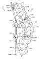
- FIG. 1shows an exemplary system for correcting a spinal deformity, according to some embodiments.
- FIG. 2is a bottom view of the system of FIG. 1 with some features not shown to facilitate understanding, according to some embodiments.
- FIG. 3shows a rod of the system of FIG. 1 , according to some embodiments.
- FIG. 4shows another rod of the system of FIG. 1 , according to some embodiments.
- FIGS. 5 a , 5 b , and 6show features of an anchor of the system of FIG. 1 , according to some embodiments.
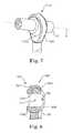
- FIGS. 7 and 8show features of another anchor of the system of FIG. 1 , according to some embodiments.
- FIGS. 9-11show still another anchor of the system of FIG. 1 , according to some embodiments.
- FIG. 12shows alternate complementary shapes for limiting roll between pre-selected angular limits, according to some embodiments.
- FIG. 13shows a vertebral anchor and first force directing member of the system of FIG. 1 , according to some embodiments.
- FIGS. 14 a and 14 bshow an adjustment mechanism of the system of FIG. 1 , according to some embodiments.
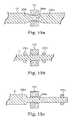
- FIGS. 15 a , 15 b , and 15 cshow some stop features of the system of FIG. 1 , according to some embodiments.
- FIG. 16is a diagrammatical view showing some of the degrees of freedom of the system of FIG. 1 , according to some embodiments.
- FIG. 17is another diagrammatical view showing some other degrees of freedom of the system of FIG. 1 , according to some embodiments.
- FIGS. 18 and 19are other diagrammatical views showing axial translation degrees of freedom, according to some embodiments.
- Some embodimentsrelate to a system for correcting spinal deformities, as well as associated methods and devices.
- the systemprovides for lateral translational corrective force(s) and/or derotational corrective force(s) on a spinal column.
- Some features of the systeminclude highly adaptive hardware for connecting the system to the spinal column, where the hardware facilitates a more natural range of motion within pre-selected limits and application of such lateral translational and/or derotational corrective force(s).
- a sagittal planedefined by two axes, one drawn between a head (superior) and tail (inferior) of the body and one drawn between a back (posterior) and front (anterior) of the body
- a coronal planedefined by two axes, one drawn between a center (medial) to side (lateral) of the body and one drawn between a head (superior) and tail (inferior) of the body
- a transverse planedefined by two axes, one drawn between a back and front of the body and one drawing between a center and side of the body.
- pitchgenerally refers to angulation, or rotation, in a first plane through which a longitudinal axis of a body orthogonally passes (e.g., rotation about a longitudinal axis corresponding to the spinal column)
- pitchrefers to angulation, or rotation, in a second plane orthogonal to the first plane
- yawrefers to angulation, or rotation, in a third plane orthogonal to the first and second planes.
- pitchis angulation in the sagittal plane
- yawis angulation in the coronal plane
- rollis angulation in the transverse plane.
- lateral translationis not limited to translation in the medial-lateral direction unless specified as such.
- FIG. 1is a perspective view of a system 10 for correcting a spinal deformity, according to some embodiments.
- the system 10includes a rod 12 , a plurality of rod anchors 14 , including a first rod anchor 14 A and a second rod anchor 14 B, a plurality of vertebral anchors 18 including a first vertebral anchor 18 A and a second vertebral anchor 18 B, a plurality of adjustment mechanisms 20 including a first adjustment mechanism 20 A and a second adjustment mechanism 20 B, and a plurality of force directing members 22 including a first force directing member 22 A and a second force directing member 22 B.
- the system 10is secured to a spinal column 24 formed of a plurality of vertebrae 26 , including a first vertebra 26 A, a second vertebra 26 B, a third vertebra 26 C, and a fourth vertebra 26 D.
- a single vertebral anchor 18is secured to a vertebra 26 at an apex of a spinal deformation or other location, with a corresponding force directing member 22 and adjustment mechanism 20 coupled to such vertebral anchor 18 .
- the first and second vertebral anchors 18 A, 18 Bare fixed to a portion of the spinal column 24 having an abnormal curvature (e.g., scoliosis) in need of correction.
- the system 10is optionally used to incrementally bring the spinal column 24 to a more natural curvature, or a single adjustment is made to the system 10 to accomplish the desired curvature.
- an abnormal curvature in the spinal column 24has been adjusted to a more natural curvature using other hardware, prior to or in conjunction with securing the system 10 to the spinal column 24 .
- FIG. 2shows the system 10 from a transverse plane view, with portions of the spinal column 24 and system 10 not shown for illustrative purposes.
- the rod 12 , the first vertebral anchor 18 A, the first adjustment mechanism 20 A, and the first force directing member 22 Aare shown along with the first vertebra 26 A and third vertebra 26 C.
- the rod 12is secured to the spinal column 24 at a pre-selected offset from a longitudinal axis of the spinal column 24 .
- the rod 12is optionally secured at an offset along a medial-lateral axis ML, or right-left axis, and anterior-posterior axis AP, or back-front axis.
- the rod 12is secured on the left side of the spinal column 24 .
- the offsetis optionally selected to cause at least a relative lateral translation (e.g., central or medial movement) and derotational shift (e.g., clockwise rotation from the bottom view of FIG. 2 ) of selected vertebrae 26 of the spinal column 24 (relative anterior-posterior movement of selected vertebrae 26 can also be accomplished) such that the spinal column 24 exhibits a more natural position.
- FIG. 3shows the rod 12 having a bend according to some embodiments.
- the rod 12is substantially rigid, defining a substantially round cross-section with a mean diameter of about 6 mm and being formed of a suitable biocompatible material, such as titanium alloy ASTM F136.
- the rod 12is adapted, or otherwise structured, to extend along the spinal column 24 .
- the bend of the rod 12is generally shown for illustrative purposes.
- the rod 12is bent in one or more of the sagittal and coronal planes. If desired, the rod 12 incorporates some flex, or springiness while substantially rigidly retaining its shape.
- the rod 12is optionally formed of a variety of materials, including stainless steel or suitable polymeric materials.
- the cross-sectional shape of the rod 12including various portions thereof, is not limited to circular cross-sections.
- the rod 12is contoured or angled to at least partially mimic a curvature (e.g., sagittal plane kyphosis or lordosis or, alternatively, an existing, defective curvature, e.g., kyphosis or lordosis) of a portion of a spinal column.
- a curvaturee.g., sagittal plane kyphosis or lordosis or, alternatively, an existing, defective curvature, e.g., kyphosis or lordosis
- the rod 12includes substantially curved, non-linear sections, or incorporates combinations of substantially bent, straight, and/or curved sections.
- the rod 12has a longitudinal axis X, as well as a first section 30 , a second section 32 , and an intermediate section 34 between the first and second sections 30 , 32 .
- the longitudinal axis Xis substantially straight.
- the longitudinal axis Xis similarly curved or angled.
- the sections 30 , 32 , 34 of the rod 12are optionally continuously formed or are formed as separate, connected parts as desired.
- the second section 32 and intermediate section 34define an inner angle Ia less than 180 degrees, for example a bend angle from about 135 to about 170 degrees, although a variety of bend angles are contemplated.
- first and second sections 30 , 32are generally non-round or otherwise define chase features.
- the second section 32forms at least one flat 36 , the second section 32 having a substantially D-shaped cross-section along at least a portion thereof.
- the first section 30 and intermediate section 34have substantially circular cross-sections, although any of the sections 30 , 32 , 34 optionally have non-circular, cross-sectional shapes as desired (e.g., star-, oval-, or square-shaped cross-sections).
- a cross-sectional shape of a particular sectionis optionally used to limit rotation of the rod 12 , although cross-sectional modifications to selectively enhance bending performance and other characteristics of the rod 12 are also contemplated (e.g. I-beam, hexagonal, or other shapes).
- At least some of the intermediate section 34optionally includes a surface treatment, such as surface roughening 38 (e.g., knurling or dimpling), or other treatment (e.g., coatings, plasma treatments, or others) for enhancing friction and/or performance.
- a surface treatmentsuch as surface roughening 38 (e.g., knurling or dimpling), or other treatment (e.g., coatings, plasma treatments, or others) for enhancing friction and/or performance.
- portions of the first and second sections 30 , 32optionally include mirror finishes, surface coatings (e.g., PTFE), or other materials or surface treatments. Though some examples have been provided, various combinations of surface treatments for portions of each of the sections 30 , 32 , 34 are contemplated.
- FIG. 4shows a rod 12 A according to some other embodiments.
- the rod 12 Ais substantially straight, or linear, and includes any of the features described in association with the rod 12 as appropriate.
- features of the rod 12 A similar to those of the rod 12are designated with the same reference number as the rod 12 followed by an “A.”
- the rod 12 Ais of a two-piece design and includes a rod adjustment mechanism 39 which provides means for increasing an effective length of the rod 12 A.
- the rod adjustment mechanism 39is optionally a female threaded sleeve adapted to extend or contract (lengthen or shorten) a gap between pieces of the rod 12 A by turning the adjustment mechanism 39 to engaging threads 37 on the sleeve.
- the adjustment mechanism 39optionally has flats or other surface features for receiving a tool (e.g., an open ended wrench).
- a toole.g., an open ended wrench
- FIGS. 5 a and 5 bshow features of the first rod anchor 14 A, according to some embodiments.
- the first rod anchor 14 Ais adapted, or otherwise structured, to be mounted, or fixed to one or more vertebrae, such as the first vertebra 26 A ( FIG. 1 ).
- the first rod anchor 14 Ais further adapted to receive, and includes means for receiving, the rod 12 such that the rod 12 is secured laterally, against lateral translation relative to the first rod anchor 14 A.
- the rod 12is substantially prevented from translating in a direction substantially perpendicular to the longitudinal axis X at the first point P 1 .
- the rod 12(shown in cut-away) is able to slide axially, or translate axially, along the longitudinal axis X, relative to the first rod anchor 14 A through a first pivot point P 1 .
- the rod 12is also able to change in pitch, yaw, and roll about the first pivot point P 1 .
- the first rod anchor 14 Ais optionally formed of biocompatible metallic materials, such as titanium, stainless steel, and/or biocompatible polymeric materials, such as PEEK and/or composite materials.
- the first rod anchor 14 Aincludes a single-piece housing 40 having receptacle portion 48 adapted, or otherwise structured, to receive the rod 12 .
- the first rod anchor 14 Afurther includes a mounting portion 50 adapted to secure the first rod anchor 14 A to one or more vertebrae, such as the first vertebra 26 A and an additional vertebra 26 above or below the first vertebra.
- the mounting portion 50is secured to a single vertebra, such as the first vertebra 26 A (e.g., laterally across the first vertebra 26 A at the pedicles, or at a single point—such as a single pedicle—on the first vertebra 26 A.
- the housing 40is of a multi-piece design (e.g., as shown in FIGS. 7-11 ).
- the mounting portion 50is adapted to be secured at two or more points, for example spanning between two vertebrae (e.g., the L3-L4 vertebrae) or spanning across a portion of a single vertebra (e.g., pedicle-to-pedicle on a single vertebra).
- two vertebraee.g., the L3-L4 vertebrae
- spanning across a portion of a single vertebrae.g., pedicle-to-pedicle on a single vertebra.
- FIG. 5 bshows the receptacle portion 48 in cross-section.
- the receptacle portion 48is generally ring-shaped and forms a passage 52 having a revolute, convex surface 54 having an upper curve 56 and a lower curve 58 .
- the receptacle portion 48is adapted to allow the rod 12 to pass through the passage 52 at the first pivot point P 1 , where the passage 52 defines a minimum effective diameter (e.g., providing appropriate clearance between the rod 12 and receptacle portion 48 ) that allows the rod 12 to slide through passage 52 .
- the passage 52also allows the rod 12 to rotate and angulate about the longitudinal axis X at the first pivot point P 1 while minimizing lateral translation or inhibiting substantial lateral translation.
- the rod 12is able to rotate and angulate about the longitudinal axis X at the first pivot point while lateral translation of the rod 12 with respect to the receptacle portion 28 is substantially limited in all planes.
- the rod 12is able to slide within the passage 52 and change in yaw, pitch, and roll at the first pivot point P 1 , while being constrained from side-to-side movement within the passage 52 at the first pivot point P 1 .
- the mounting portion 50includes a stem 60 and a pedestal 62 , the pedestal 62 having an central portion 64 , a first anchor point 66 , and a second anchor point 68 , the central portion 64 extending between the first and second anchor points 66 , 68 and each of the anchor points 66 , 68 defining a surface suitable for mounting the first rod anchor 14 A to one or more vertebrae 26 .
- the first and second anchor points 66 , 68optionally include through holes 70 , 72 , respectively, for receiving a fastener (not shown), such as a pedicle screw or similar device to secure the mounting portion 50 to one or more vertebra 26 , such as the first vertebra 26 A ( FIG. 1 ).
- the first rod anchor 14 Ais adapted, or otherwise structured, to limit pitch and yaw of the rod 12 to a predefined range.
- the rod 12is able to angulate within a range until opposing surfaces of the rod 12 , contact, or bind with the upper and lower curves 56 , 58 of the convex surface 54 .
- a radius of curvature of the convex surface 54is optionally selected to control a range of motion of the rod 12 .
- pitch and yaw of the rod 12is limited to within an angular range Ra of about 60 degrees, for example.
- various means of limiting roll and/or sliding of the rod 12 within a predefined rangeare also contemplated.
- FIG. 6shows the first rod anchor 14 A with the mounting portion 50 being adapted to act as a fastener, similar to that of a pedicle screw.
- the first rod anchor 14 aoptionally includes fastener means for securing the first anchor 14 A to one of the vertebra 26 .
- FIGS. 5 a , 5 b , and 6are illustrative of some potential features the system 10
- FIGS. 7 and 8show a first rod anchor 114 A according to some other embodiments, where FIG. 7 is a perspective view with the rod 12 received by the first rod anchor 114 A and FIG. 8 is a cross-sectional view of the first rod anchor 114 A with the rod 12 removed.
- the first rod anchor 114 Ais substantially similar to the first rod anchor 14 A, although a housing 140 of the first rod anchor 114 A includes a receptacle portion 148 A and a sleeve portion 148 B.
- the sleeve portion 148 Bis substantially spherical in shape and the receptacle portion 148 A forms a substantially spherical mating race for the sleeve portion 148 B.
- the receptacle portion 148 Ahas a revolute, substantially concave surface 154 A and the sleeve portion 148 B has a revolute, substantially convex surface 154 B.
- the surfaces 154 A, 154 Bare adapted, or otherwise structured, to form a substantially complementary fit with one another, such that the sleeve portion 148 B is captured by the receptacle portion 148 A and is allowed relative rotational and angular movement with respect to the receptacle portion 148 A.
- the sleeve portion 148 Bhas a passage 152 defining a pivot point P 11 through which the rod 12 is able to be slidably received.
- the complementary relationship between the sleeve portion 148 B and the receptacle portion 148 Ais optionally designed to restrict, or limit, certain relative movement of the rod 12 with respect to the first rod anchor 114 A.
- pitch and yaw of the rod 12 about the pivot point P 11is limited when opposing surfaces of the rod 12 contact the receptacle portion 148 A proximate a front 156 and/or a back 158 of the receptacle portion 148 A.
- FIG. 9is a perspective view of the second rod anchor 14 B and FIGS. 10 and 11 are perspective views of portions thereof.
- the second rod anchor 14 Bis adapted to be fixed, and provides means for fixation to a second vertebra, such as a second vertebra 26 B ( FIG. 1 ).
- the second rod anchor 14 Bis further adapted to receive, and provides means for receiving the rod 12 ( FIG. 1 ) such that the second rod anchor 14 B limits translational movement of the rod 12 except along the longitudinal axis X and allows the rod 12 to change in at least pitch and yaw about a second pivot point P 2 .
- the second rod anchor 14 Bis optionally substantially similar to the first rod anchor 14 A or first rod anchor 114 A, including any desired combination of previously-described features.
- the second rod anchor 14 Bis optionally formed of biocompatible metallic materials, such as titanium or stainless steel and/or biocompatible polymeric materials, such as PEEK.
- the second rod anchor 14 Bincludes a housing 200 having receptacle portion 202 and a sleeve portion 204 adapted to receive the rod 12 , the second rod anchor 14 B further including a mounting portion (e.g., similar to the mounting portion 50 of the first rod anchor 14 A) adapted to secure the second rod anchor 14 B to the second vertebra 26 B.
- the second rod anchor 14 Bis optionally adapted, or otherwise structured, to limit rotation, or roll, of the rod 12 about the longitudinal axis X of the rod 12 ( FIG. 3 ).
- the second rod anchor 14 Bprovides means for allowing the rod 12 to angulate without substantial lateral translation relative to the second rod anchor 14 B or substantial rotation about the longitudinal axis X.
- the sleeve portion 204is optionally spherical in shape and the receptacle portion 202 forms a substantially spherical mating race, where rotation of the sleeve portion 204 relative to the receptacle portion 202 is substantially inhibited in at least one plane.
- FIG. 10shows the receptacle portion 202 and FIG. 11 shows the sleeve portion 204 , where the receptacle portion 202 has a revolute, substantially concave inner surface 210 and the sleeve portion 204 has a revolute, substantially convex outer surface 212 .
- the surfaces 210 , 212are adapted to form a substantially complementary fit with one another, such that the sleeve portion 204 is captured by the receptacle portion 202 and is allowed relative angular movement with respect to the receptacle portion 202 .
- the receptacle portion 202also includes a pair of protrusions 216 (e.g., pins), extending inwardly from and at opposite sides of the inner surface 210 .
- the sleeve portion 204has a circumferential groove 218 adapted to slidably receive the protrusions 216 and an internal passage 220 through which the rod 12 is able to be slidably received.
- a pivot point P 2is also defined in the passage 220 , the rod 12 passing through the pivot point P 2 .
- the passage 220optionally has a non-circular cross-section (e.g., a substantially D-shaped cross-section corresponding to the second section 32 of the rod 12 ). Upon mating the non-circular cross-sections of the rod 12 and the passage 220 , rotation of the rod 12 relative to the sleeve portion 204 is substantially inhibited.
- a non-circular cross-sectione.g., a substantially D-shaped cross-section corresponding to the second section 32 of the rod 12 .
- the pitch and yaw of the rod 12are able to change.
- Relative rotation between the sleeve portion 204 and the receptacle portion 202is substantially inhibited.
- relative rotation between the sleeve portion 204 and the receptacle portion 202is also substantially inhibited, relative rotation between the rod 12 and the second rod anchor 14 B is substantially inhibited or limited, allowing the rod 12 to be maintained at a pre-selected rotational position relative to the second rod anchor 14 B.
- each of the passage 220 and rod 12can be selected to allow some degree of rotation about the longitudinal axis X within a predefined range, including, for example, that shown in FIG. 12 , where the rod 12 is shown with features allowing rotation up to a stop 220 A formed by the sleeve 204 .
- the cross-sectional shape of the rod 12is also optionally selected to limit axial translation of the rod 12 as desired.
- the second rod anchor 14 Bis also optionally adapted to restrict, or limit angulation of the rod 12 (e.g., pitch and yaw) with respect to the second rod anchor 14 B.
- pitch and yaw of the rod 12 about the pivot point P 2is limited when the rod 12 contacts the receptacle portion 202 proximate a front 222 and/or a back 224 of the receptacle portion 202 .
- a size and shape of the receptacle and/or sleeve portions 202 , 204is selected to define such limit(s) as desired.
- FIG. 13shows the first vertebral anchor 18 A and first force directing member 22 A from a front elevation view.
- the first vertebral anchor 18 Aalso described as an anchor arm, is adapted to be fixed, and provides means for fixation, to a third vertebra 26 C ( FIG. 1 ).
- the first vertebral anchor 18 Ais fixed to a portion of the spinal column 24 ( FIG. 1 ) having an abnormal curvature in need of correction.
- first and second vertebral anchors 18 A, 18 Bare optionally substantially similar, and thus various features of both the first and second vertebral anchors 18 A, 18 B are described in association with the first vertebral anchor 18 A, where when referenced, features of the first vertebral anchor 18 A are designated with reference numbers followed by an “A” and similar features of the second vertebral anchor 18 B are designated with similar reference numbers followed by a “B.”
- the first vertebral anchor 18 Aincludes an arm 250 A and a head 252 A.
- the arm 250 Aextends from the head 252 A to a terminal end 254 A and is disposed generally perpendicular to the head 252 A.
- the arm 250 Ais optionally rotatable relative to the head 252 B and is adapted to extend across a portion of the third vertebra 26 C, for example, from one side of the spinal column 24 to an opposite side of the spinal column 24 .
- the first vertebral anchor 18 Ais secured to the third vertebra 26 C such that the arm 250 A extends across the third vertebra 26 C through a hole or hollowed portion in the spinous processes (not shown) of the third vertebra 26 C.
- the head 252 Ais adapted, or is otherwise structured, to be fixed to a portion of the third vertebra 26 C, such as a pedicle of the third vertebra 26 C.
- the head 252 Aoptionally includes and/or is adapted to work in conjunction with any of a variety of structures capable of engaging the third vertebra 26 C.
- the first vertebral anchor 18 Aoptionally includes a pedicle screw 256 A secured through the head 252 A to a pedicle of the third vertebra 26 C.
- the first force directing member 22 Ais secured to the first vertebral anchor 18 A at an appropriate location on the first vertebral anchor 18 A.
- the first force directing member 22 Ais secured to the first vertebral anchor 18 A at least at the terminal end 254 A of the arm 250 A such that the first force directing member 22 A extends from the terminal end 254 A of the arm 250 A.
- vertebral anchorsalso described as “implants” in accordance with some embodiments of the system 10 are set forth in U.S. application Ser. No. 11/196,952, filed on Aug. 3, 2005 and entitled DEVICE AND METHOD FOR CORRECTING A SPINAL DEFORMITY, as well as Ser. No. 12/134,058, filed on Jun. 5, 2008 and entitled MEDICAL DEVICE AND METHOD TO CORRECT DEFORMITY, the entire contents of both of which are hereby incorporated by reference.
- FIGS. 14 a and 14 bshow the first adjustment mechanism 20 A, where FIG. 14 b shows the first adjustment mechanism 20 A with a portion removed to illustrate inner features thereof.
- the first adjustment mechanism 20 Aprovides means for securing the first force directing member 22 A to the rod 12 .
- the first adjustment mechanism 20 Aalso described as a tensioner or coupler, is further adapted to adjust, and provides means for adjusting a length of the first force directing member 22 A.
- the first and second adjustment mechanisms 20 A, 20 Bare optionally substantially similar.
- first and second adjustment mechanisms 20 A, 20 Bare described in association with the first adjustment mechanism 20 A, where features of the first adjustment mechanism 20 A are designated with reference numbers followed by an “A” and similar features of the second adjustment mechanism 20 B are designated with the same reference numbers followed by a “B.”
- the first adjustment mechanism 20 Aincludes a reel 260 A, a circumferential gear 262 A surrounding the reel 260 A, a vertical gear 264 A in contact with the circumferential gear 262 A, an actuation head 268 A, and a housing 270 A.
- the reel 260 A, as well as the circumferential gear 260 A and vertical gear 264 Aare maintained at least partially within the housing 270 A.
- the housing 270 Ais adapted to be secured to the rod 12 .
- the housing 270 Aoptionally forms a central lumen through which the rod 12 is receivable. Upon inserting the rod 12 through the central lumen, the housing 270 A is adapted to be clamped onto the rod 12 .
- the housing 270 Aincorporates a clamshell design (e.g., a first portion adjustably secured to a second portion) adapted to be tightened onto the rod 12 (e.g., using one or more fasteners).
- the first adjustment mechanism 20 Ais substantially fixed with respect to the rod 12 . In other embodiments, however, the first adjustment mechanism 20 A is movable with respect to the rod 12 , for example being able to rotate about the rod 12 .
- the first force directing member 22 Ais attached or secured to the reel 260 A and passes out of the housing 270 A through an appropriately sized opening in the housing 270 A.
- Actuation of the vertical gear 264 A via the actuation head 266 Aturns the circumferential gear 262 A, which turns the reel 260 A, thus winding (or unwinding, depending on the direction in which the reel 260 A is turned) the first force directing member 22 A about the reel 260 A.
- Rotation of the reel 260 A in the appropriate directiondraws the first force directing member 22 A in toward the first adjustment mechanism 20 A, pulling the first vertebral anchor 18 A ( FIG. 13 ) toward the first adjustment mechanism 20 A according to some methods of correcting a spinal defect.
- adjustment membersalso described as “adjustment mechanisms”
- adjustment mechanismsin accordance with some embodiments of the system 10 are set forth in U.S. application Ser. No. 11/196,952, filed on Aug. 3, 2005 and entitled DEVICE AND METHOD FOR CORRECTING A SPINAL DEFORMITY, as well as Ser. No. 12/134,058, filed on Jun. 5, 2008 and entitled MEDICAL DEVICE AND METHOD TO CORRECT DEFORMITY, the entire contents of both of which are hereby incorporated by reference.
- first and second force directing members 22 A, 22 Bare optionally substantially similar, and thus various features of both the first and second force directing members 22 A, 22 B are described in association with the first force directing member 22 A, where features of the first force directing member 22 A are designated with reference numbers followed by an “A” and similar features of the second force directing member 22 B are designated with similar reference numbers followed by a “B.”
- the first force directing member 22 Ais substantially flexible such that the first force directing member 22 A is able to be pivoted in a multiple directions and/or be spooled or wound, for example.
- Suitable flexible materials for forming the first force directing member 22 Ainclude wire and stranded cables, monofilament polymer materials, multifilament polymer materials, multifilament carbon or ceramic fibers, and others.
- the first force directing member 22 Ais formed of stainless steel or titanium wire or cable, although a variety of materials are contemplated.
- the first force directing member 22 Aalso described as a connector or cable, is adapted to be secured to the first vertebral anchor 18 A and the first adjustment member 20 A, the force directing member 22 A defining an effective length between the first adjustment mechanism 20 A and the first vertebral anchor 18 A, and thus the rod 12 (although, in some embodiments, the first force directing member 22 A is secured directly to the rod 12 ).
- the first adjustment mechanism 20 Ais adapted to modify, and provides means for modifying, the effective length of the force directing member 22 A.
- the first force directing member 22 Ahas a body 280 A and extends from a first end 282 A to a second end 284 A.
- FIG. 1shows the assembled system 10 .
- assembly of the system 10includes securing the first and second force directing members 22 A, 22 B to the first and second vertebral anchors 18 A, 18 B, respectively.
- the first and second force directing members 22 A, 22 Bare also secured to the first and second adjustment mechanisms 20 A, 20 B.
- the first and second adjustment mechanisms 20 A, 20 Bare secured to the rod 12 .
- the first and second rod anchors 14 A, 14 Bare secured to the first and second vertebrae 26 A, 26 B, respectively.
- the rod 12is received in the first and second rod anchors 14 A, 14 B to secure the rod 12 against lateral translation relative to the spinal column 24 .
- the first and second vertebral anchors 18 A, 18 Bare secured to the third and fourth vertebrae 26 C, 26 D.
- the first and second adjustment mechanisms 20 A, 20 Bare adjusted as desired to pull the first and second vertebral anchors 18 A, 18 B toward the first and second adjustment mechanisms 20 A, 20 B, and thus the rod 12 .
- the first force directing member 22 Ais assembled to the first vertebral anchor 18 A by securing the first end 282 A of the first force directing member 22 A to the first vertebral anchor 18 A proximate the terminal end 254 A thereof.
- the first force directing member 22 Ais secured at the terminal end 254 A of the first vertebral anchor 18 A, and extends along at least a portion of the arm 250 A to the head 252 A, although the first force directing member 22 A is attached at any location along the arm 250 A and/or the head 252 A of the first vertebral anchor 18 A as appropriate.
- the first force directing member 22 Ais securable to the first vertebral anchor 18 A via a variety of methods, including welding, adhesives, tying, and/or screw fixation, for example.
- the second force directing member 22 B and the second vertebral anchor 18 Bare optionally secured or connected together using similar approaches.
- the first force directing member 22 Aextends to the first adjustment mechanism 20 A, enters the housing 250 A, and is wound about the reel 260 A, thereby coupling the first adjustment mechanism 20 A to the first vertebral anchor 18 A as well as the rod 12 .
- the first force directing member 22 Ais secured to the reel 260 A via welding, screw fixation, adhesives, and/or is sufficiently wound about the reel 260 A for frictional retention of the first force directing member 22 A on the reel 260 A.
- the second force directing member 22 A and the second adjustment mechanism 20 Bare optionally secured or connected together using similar approaches.
- the rod 12is received by the housings 40 , 200 of the first and second rod anchors 14 A, 14 B, respectively.
- Features of the first and second rod anchors 14 A, 14 Bare selected to limit pitch, yaw, roll, and axial sliding of the rod 12 as desired.
- the rod 12is secured against lateral translation relative to the longitudinal axis of the spinal column 14 by securing the first and second rod anchors 14 A, 14 B to at least the first and second vertebra 26 A, 26 B, respectively.
- the first rod anchor 14 Ais secured to at least the first vertebra 26 A, for example by screwing the first rod anchor 14 A to the first vertebra 26 A (e.g., at or near the transverse processes) using one or more pedicle screws.
- the second rod anchor 14 Bis similarly secured to at least the second vertebra 26 B.
- the first rod anchor 14 A and/or the second rod anchor 14 Bare optionally secured to multiple vertebrae 26 for enhanced stability.
- the rod 12is attached by the rod anchors 14 A, 14 B to transverse processes on the left side of the spinal column 24 and is able to slide axially relative to the first and/or second rod anchors 14 A, 14 B.
- the rod 12is attached by the rod anchors 14 A, 14 B to the right side of the spinal column 24 , on different sides of the spinal column 24 (e.g., the first rod anchor 14 A on the left side and the second rod anchor 14 B on the right side), or along the mid-line of the spinal column 24 .
- the rod 12is adjustable length to compensate for changes in length of the spinal column 24 . Regardless, the interaction between the rod 12 and the first and second rod anchors 14 A, 14 B helps facilitate growth and more natural movement of the spinal column 24 .
- FIGS. 15 a , 15 b , and 15 cshow various stop features 286 for limiting axial sliding, or translation of the rod 12 relative to a rod anchor, such as the first rod anchor 14 A.
- a rod anchorsuch as the first rod anchor 14 A.
- sliding of the rod 12 in a particular axial directionis substantially limited, or arrested, when a stop feature 286 engages, or abuts an adjacent rod anchor 14 .
- the rod 12optionally includes a narrowed portion 286 a received in the first rod anchor 14 A with wider, adjacent portions 286 b of the rod 12 limiting axial sliding of the rod 12 .
- axial sliding of the rod 12is substantially prevented by locating the stop features 286 adjacent the first rod anchor 14 A, there is still some tolerance allowed, or play, as appropriate in the fit between the wider portions 286 b of the rod 12 and the first rod anchor 14 A.
- the system 10optionally includes stops 286 c , or collars, that are fit onto the rod 12 adjacent the first rod anchor 14 A to substantially limit axial sliding of the rod 12 within the first rod anchor 14 A.
- the stops 286 care metal or polymeric collars crimped onto the rod 12 , although a variety of designs and methods of securing are employed as desired.
- axial sliding of the rod 12is substantially prevented with respect to the first rod anchor 14 A, there is still some limited play or slop as appropriate in the fit between the rod 12 and the stops 286 c.
- the system 10optionally utilizes both a stop 286 c and a narrowed portion 286 a with a wider portion 286 b to limit axial sliding of the rod 12 relative to the first rod anchor 14 A within a desired range of motion.
- the stop 286 cis located toward an end of the rod 12 on one side of the first rod anchor 14 A and the wider portion 286 b is located on the other side of the first rod anchor 14 A with a desired spacing between the stop 286 c and the wider portion 286 b . Any combination of stop features 286 and spacing are implemented as appropriate.
- FIG. 16is a diagrammatical view of a system 10 A similar to that of FIG. 1 , where FIG. 16 illustrates various degrees of freedom of the rod 12 at the first and second rod anchors 14 A, 14 B, according to some embodiments.
- the system 10 Afurther includes a third vertebral anchor 18 C secured to a fifth vertebra 26 D.
- the third vertebral anchoris substantially similar to the first and/or second vertebral anchors 18 A, 18 B.
- the system 10also optionally includes a corresponding third force directing member 22 C, e.g., a cable or wire, and a third adjustment mechanism 20 C.
- adjustment mechanisms 20including means for adjusting the effective length of the force directing members 22 have been described, in some embodiments one or more of the adjustment mechanisms 20 acts as a means for coupling a corresponding force directing member to the rod 12 without incorporating such adjustment features.
- the third adjustment mechanism 20 Cis optionally a crimp or fastener means for securing the force directing member 22 C to the rod 12 (e.g., a clamp or crimp).
- the rod 12is bent (e.g., as shown in FIG. 3 ) and, as designated by the directional arrows, is free to change in pitch, yaw, and roll, as well as to slide axially along the longitudinal axis X at the first rod anchor 14 A (and thus, at the first pivot point P 1 ) and is free to change in pitch and yaw at the second rod anchor 14 B while relative changes in roll and axial sliding are substantially limited or substantially prevented at the second rod anchor 14 B (and thus, at the second pivot point P 2 ).
- collars 288 A or other stop featuresare located on the rod 12 (e.g., crimped onto the rod 12 ) on either side of the second rod anchor 14 B in order to inhibit sliding movement of the rod 12 .
- a stop feature 288 B(such as one of those previously described) is located proximate a terminus of the rod 12 in order to help prevent the rod 12 from slipping off the first rod anchor 14 A.
- the interaction between the vertebral anchors 18 A, 18 B, adjustment mechanisms 20 A, 20 B, and in particular the flexible nature of their respective coupling through use of the force directing members 22 A, 22 Ballows the system 10 to move dynamically with the spinal column 24 , while exerting and/or maintaining a corrective force (e.g., lateral and derotational forces) on the third and fourth vertebrae 26 C, 26 D.
- a corrective forcee.g., lateral and derotational forces
- the system 10is semi-constrained, providing a lateral and derotational anchor point while facilitating at least some degree of natural movement in the spinal column 24 .
- the bend in the rod 12is oriented and maintained in a desired rotational position. Maintaining the rotational orientation at one end (i.e., at the second rod anchor 14 B) is useful, for example, to help ensure that the bend or shape of the rod 12 consistently follows or otherwise appropriately tracks a desired curvature of a spinal column 24 . Freedom of rotation at the other end of the rod 12 (i.e., at the first rod anchor 14 A), however, still permits the spinal column 24 to have more natural movement while the corrective forces are being applied.
- the spinal column 24(and thus, the person) is able to twist, bend side-to-side, and bend forward-and-backward in a more natural manner while corrective forces are being applied to the spinal column 24 .
- the effective lengths of the force directing members 22 A, 22 Bare adjusted (e.g., periodically or all at one time), bringing the spinal column into natural alignment, while the system 10 still facilitates a more natural movement of the spinal column 24 (e.g., twisting and bending forward-and-backward and side-to-side) due to the freedom of movement afforded by the system 10 .
- FIG. 17is a diagrammatical view of a system 10 B illustrating various degrees of freedom of the rod 112 at the first rod anchor 14 A and a second rod anchor 290 substantially similar to the first rod anchor 14 A, according to some other embodiments of the system 10 .
- the rod 112is substantially straight ( FIG. 4 ) and, as designated by the directional arrows, is free to change in pitch, yaw, and roll, as well as to slide axially along the longitudinal axis X, at each of the first and second rod anchors 14 A, 290 .
- each of the first and second rod anchors 14 A, 290 shown generally in FIG. 16are substantially the same as the first rod anchor 14 A shown in FIGS. 5 a and 5 b , for example. In other embodiments, each of the first and second rod anchors 14 A, 290 are substantially the same as the first rod anchor 114 A shown in FIGS. 7 and 8 , although any combination of the previously-described anchor features described in association with any of the rod anchors 14 A, 114 A, 14 B are contemplated.
- the rod 112also optionally includes stop features 300 , such as the stop features 286 previously described, to help prevent the rod 112 from slipping out of the first and second rod anchors 14 A, 290 .
- the rod 112is able to slide axially, along the longitudinal axis X ( FIG. 4 ) until one of the stop features 300 contacts one of the first and second rod anchors 14 A, 290 .
- the system 10 Bprovides dynamic adjustment and movement with the spine, while exerting a corrective force (e.g., translational and derotational forces) on the vertebrae 26 (e.g., the third and fourth vertebrae 24 C, 24 D).
- FIGS. 18 and 19show systems 10 C, 10 D, respectively, demonstrating variations in axial rod constraint according to some embodiments.
- the systems 10 C, 10 Dare each shown including a first rod anchor 360 and a second rod anchor 370 which incorporate features of any of the anchors previously described.
- the axial arrowsindicate freedom of movement of the associated rods, although a designation of degrees of freedom in pitch, yaw, and roll at the anchors 360 , 370 are left from FIGS. 18 and 19 for ease of illustration.
- Various degrees of freedom at the anchors 360 , 370are incorporated as appropriate.
- the system 10 Cincludes a rod 375 (e.g., similar to the rod 12 A) including a rod adjustment mechanism 376 (e.g., similar to the rod adjustment mechanism 39 ), a first stop feature 380 A, a second stop feature 380 B, and a third stop feature 380 C, the stop features 380 A, 380 B, 380 C being secured to and/or formed with the rod 375 (e.g., similar to the stop features being similar to any of the stop features 286 previously described).
- the rod 375is substantially constrained against axial sliding by the second and third stop features 380 B, 380 C at the second rod anchor 370 and is allowed some axial sliding, or axial translation, outwardly away from the first stop feature 380 A.
- the stop features 286 and the first and second rod anchors 360 , 370provide means for imposing a distraction force on the spinal column 24 and/or for limiting compression of the spinal column 24 along one or more sides of the spinal column 24 (e.g., left, right, anterior, and/or posterior sides).
- the rod adjustment mechanism 376is used to apply a distraction force by expanding an effective length of the rod 375 such that the first and second stop features 380 A, 380 B engage the first and second rod anchors 360 , 370 resulting in a compressive force on the rod 375 that the rod 375 substantially rigidly resists.
- the compressive force on the rod 375results in a distraction, or elongation force on a side of the spinal column 24 to which the anchors 360 , 370 of the system 10 C are coupled.
- the stop featuresadditionally or alternatively provide a limit on compression of the spinal column 24 at the first side of the spinal column 24 by limiting relative movement of the anchors 36 , 370 toward one another on the rod 375 .
- the rod 375 of the system 10 Cis placed under a compressive load, the rod 375 is able to move axially in a first direction, e.g., to allow further distraction and/or natural movement—e.g., such that the spinal column 24 (and thus, the person) is able to twist, bend side-to-side, and bend forward-and-backward in a more natural manner while distractive forces are being applied to the spinal column 24 .
- axial movement of the rod 375 in a second direction generally opposite the first directionis limited (e.g., thereby limiting compression of the spinal column 24 beyond the axial limit set by the stop features 286 ).
- a distraction forceis applied to both sides of the spinal column 24 , to an anterior side of the spinal column 24 , to a posterior side of the spinal column 24 , or combinations thereof.
- the system 10 Dincludes a rod 400 (e.g., similar to the rod 12 A) including a rod adjustment mechanism 402 (e.g., similar to rod adjustment mechanism 39 ), a first stop feature 410 A and a second stop feature 410 B, the stop features 410 A, 410 B being secured to and/or formed with the rod 400 (e.g., similar to any of the stop features 286 previously described).
- a rod 400e.g., similar to the rod 12 A
- a rod adjustment mechanism 402e.g., similar to rod adjustment mechanism 39
- the stop features 410 A, 410 Bbeing secured to and/or formed with the rod 400 (e.g., similar to any of the stop features 286 previously described).
- the rod 400is substantially constrained against axial sliding and/or outward expansion by the first and second stop features 410 A, 410 B, the stop features 41 A, 410 B providing means for imposing a compressive force on the spinal column 24 and/or for limiting distraction of the spinal column 24 along one or more sides of the spinal column 24 (e.g., left, right, anterior, and/or posterior sides).
- the rod adjustment mechanism 402is used to apply a contraction or tensioning force on the spinal column to which the system 10 D is coupled by contracting or shortening the rod 400 using the adjustment mechanism 402 such that the first and second stop features 410 A, 410 B engage the first and second rod anchors 360 , 370 to apply a compressive force to the spinal column (not shown).
- the rod 400 of the system 10 Dis placed under a tensile load, the rod 400 is able to move axially in a first direction, for example, to allow further compression of the spinal column 24 (and thus, the person) is able to twist, bend side-to-side, and bend forward-and-backward in a more natural manner while compressive forces are being applied to the spinal column 24 .
- Axial movement of the rod 400is still substantially limited in a second direction generally opposite the first direction, for example, limiting distraction of the spinal column 24 beyond the axial limit set by the stop features 286 .
- system 10 Dis described as applying a compressive force and/or distraction limit to one side of the spinal column 24 , in other embodiments a tensile, or compressive force is applied to both sides of the spinal column 24 , to an anterior side of the spinal column 24 , to a posterior side of the spinal column 24 , or combinations thereof.
- the system 10 Dcan apply a compressive force and/or distraction limit to one side of the spinal column 24
- the system 10 Capplies a distraction force and/or compression limit to the opposite side of the spinal column 24 .
- systems, methods, and devices according to the various embodiments provided hereinhelp minimize a number of anchor points utilized for correction, facilitate use of straight or contoured rods, and/or help promote a more natural, physiologic motion of the spinal column 24 during or after correction of the deformity.
Landscapes
- Health & Medical Sciences (AREA)
- Orthopedic Medicine & Surgery (AREA)
- Life Sciences & Earth Sciences (AREA)
- Neurology (AREA)
- Surgery (AREA)
- Heart & Thoracic Surgery (AREA)
- Engineering & Computer Science (AREA)
- Biomedical Technology (AREA)
- Nuclear Medicine, Radiotherapy & Molecular Imaging (AREA)
- Medical Informatics (AREA)
- Molecular Biology (AREA)
- Animal Behavior & Ethology (AREA)
- General Health & Medical Sciences (AREA)
- Public Health (AREA)
- Veterinary Medicine (AREA)
- Surgical Instruments (AREA)
- Prostheses (AREA)
- Orthopedics, Nursing, And Contraception (AREA)
Abstract
Description
Claims (20)
Priority Applications (4)
| Application Number | Priority Date | Filing Date | Title |
|---|---|---|---|
| US13/722,690US9358044B2 (en) | 2009-03-26 | 2012-12-20 | Semi-constrained anchoring system |
| US15/175,514US11154329B2 (en) | 2009-03-26 | 2016-06-07 | Semi-constrained anchoring system |
| US17/496,915US12137943B2 (en) | 2009-03-26 | 2021-10-08 | Semi-constrained anchoring system |
| US18/918,730US20250032153A1 (en) | 2009-03-26 | 2024-10-17 | Semi-Constrained Anchoring System |
Applications Claiming Priority (3)
| Application Number | Priority Date | Filing Date | Title |
|---|---|---|---|
| US12/411,562US8357183B2 (en) | 2009-03-26 | 2009-03-26 | Semi-constrained anchoring system |
| US12/411,558US8357182B2 (en) | 2009-03-26 | 2009-03-26 | Alignment system with longitudinal support features |
| US13/722,690US9358044B2 (en) | 2009-03-26 | 2012-12-20 | Semi-constrained anchoring system |
Related Parent Applications (1)
| Application Number | Title | Priority Date | Filing Date |
|---|---|---|---|
| US12/411,562ContinuationUS8357183B2 (en) | 2009-03-26 | 2009-03-26 | Semi-constrained anchoring system |
Related Child Applications (1)
| Application Number | Title | Priority Date | Filing Date |
|---|---|---|---|
| US15/175,514ContinuationUS11154329B2 (en) | 2009-03-26 | 2016-06-07 | Semi-constrained anchoring system |
Publications (2)
| Publication Number | Publication Date |
|---|---|
| US20130184757A1 US20130184757A1 (en) | 2013-07-18 |
| US9358044B2true US9358044B2 (en) | 2016-06-07 |
Family
ID=42237301
Family Applications (7)
| Application Number | Title | Priority Date | Filing Date |
|---|---|---|---|
| US12/411,558Expired - Fee RelatedUS8357182B2 (en) | 2009-03-26 | 2009-03-26 | Alignment system with longitudinal support features |
| US12/411,562Expired - Fee RelatedUS8357183B2 (en) | 2009-03-26 | 2009-03-26 | Semi-constrained anchoring system |
| US12/817,886Expired - Fee RelatedUS8518086B2 (en) | 2009-03-26 | 2010-06-17 | Semi-constrained anchoring system |
| US13/722,685Expired - Fee RelatedUS9173681B2 (en) | 2009-03-26 | 2012-12-20 | Alignment system with longitudinal support features |
| US13/722,690Expired - Fee RelatedUS9358044B2 (en) | 2009-03-26 | 2012-12-20 | Semi-constrained anchoring system |
| US15/175,514ActiveUS11154329B2 (en) | 2009-03-26 | 2016-06-07 | Semi-constrained anchoring system |
| US17/496,915Active2030-02-25US12137943B2 (en) | 2009-03-26 | 2021-10-08 | Semi-constrained anchoring system |
Family Applications Before (4)
| Application Number | Title | Priority Date | Filing Date |
|---|---|---|---|
| US12/411,558Expired - Fee RelatedUS8357182B2 (en) | 2009-03-26 | 2009-03-26 | Alignment system with longitudinal support features |
| US12/411,562Expired - Fee RelatedUS8357183B2 (en) | 2009-03-26 | 2009-03-26 | Semi-constrained anchoring system |
| US12/817,886Expired - Fee RelatedUS8518086B2 (en) | 2009-03-26 | 2010-06-17 | Semi-constrained anchoring system |
| US13/722,685Expired - Fee RelatedUS9173681B2 (en) | 2009-03-26 | 2012-12-20 | Alignment system with longitudinal support features |
Family Applications After (2)
| Application Number | Title | Priority Date | Filing Date |
|---|---|---|---|
| US15/175,514ActiveUS11154329B2 (en) | 2009-03-26 | 2016-06-07 | Semi-constrained anchoring system |
| US17/496,915Active2030-02-25US12137943B2 (en) | 2009-03-26 | 2021-10-08 | Semi-constrained anchoring system |
Country Status (8)
| Country | Link |
|---|---|
| US (7) | US8357182B2 (en) |
| EP (2) | EP2452643B1 (en) |
| JP (1) | JP5694288B2 (en) |
| CN (1) | CN102365057B (en) |
| AU (1) | AU2010229850B2 (en) |
| CA (1) | CA2756734C (en) |
| ES (2) | ES2439865T3 (en) |
| WO (1) | WO2010111500A2 (en) |
Cited By (18)
| Publication number | Priority date | Publication date | Assignee | Title |
|---|---|---|---|---|
| US10349982B2 (en) | 2011-11-01 | 2019-07-16 | Nuvasive Specialized Orthopedics, Inc. | Adjustable magnetic devices and methods of using same |
| US10478232B2 (en) | 2009-04-29 | 2019-11-19 | Nuvasive Specialized Orthopedics, Inc. | Interspinous process device and method |
| US10617453B2 (en) | 2015-10-16 | 2020-04-14 | Nuvasive Specialized Orthopedics, Inc. | Adjustable devices for treating arthritis of the knee |
| US10646262B2 (en) | 2011-02-14 | 2020-05-12 | Nuvasive Specialized Orthopedics, Inc. | System and method for altering rotational alignment of bone sections |
| US10660675B2 (en) | 2010-06-30 | 2020-05-26 | Nuvasive Specialized Orthopedics, Inc. | External adjustment device for distraction device |
| US10729470B2 (en) | 2008-11-10 | 2020-08-04 | Nuvasive Specialized Orthopedics, Inc. | External adjustment device for distraction device |
| US10743794B2 (en) | 2011-10-04 | 2020-08-18 | Nuvasive Specialized Orthopedics, Inc. | Devices and methods for non-invasive implant length sensing |
| US10751094B2 (en) | 2013-10-10 | 2020-08-25 | Nuvasive Specialized Orthopedics, Inc. | Adjustable spinal implant |
| US10835290B2 (en) | 2015-12-10 | 2020-11-17 | Nuvasive Specialized Orthopedics, Inc. | External adjustment device for distraction device |
| US10918425B2 (en) | 2016-01-28 | 2021-02-16 | Nuvasive Specialized Orthopedics, Inc. | System and methods for bone transport |
| US11154329B2 (en) | 2009-03-26 | 2021-10-26 | K2M, Inc. | Semi-constrained anchoring system |
| US11191579B2 (en) | 2012-10-29 | 2021-12-07 | Nuvasive Specialized Orthopedics, Inc. | Adjustable devices for treating arthritis of the knee |
| US11202707B2 (en) | 2008-03-25 | 2021-12-21 | Nuvasive Specialized Orthopedics, Inc. | Adjustable implant system |
| US11234849B2 (en) | 2006-10-20 | 2022-02-01 | Nuvasive Specialized Orthopedics, Inc. | Adjustable implant and method of use |
| US11246694B2 (en) | 2014-04-28 | 2022-02-15 | Nuvasive Specialized Orthopedics, Inc. | System for informational magnetic feedback in adjustable implants |
| US11357549B2 (en) | 2004-07-02 | 2022-06-14 | Nuvasive Specialized Orthopedics, Inc. | Expandable rod system to treat scoliosis and method of using the same |
| US11439449B2 (en) | 2014-12-26 | 2022-09-13 | Nuvasive Specialized Orthopedics, Inc. | Systems and methods for distraction |
| US11612416B2 (en) | 2015-02-19 | 2023-03-28 | Nuvasive Specialized Orthopedics, Inc. | Systems and methods for vertebral adjustment |
Families Citing this family (85)
| Publication number | Priority date | Publication date | Assignee | Title |
|---|---|---|---|---|
| US7833250B2 (en) | 2004-11-10 | 2010-11-16 | Jackson Roger P | Polyaxial bone screw with helically wound capture connection |
| US8876868B2 (en) | 2002-09-06 | 2014-11-04 | Roger P. Jackson | Helical guide and advancement flange with radially loaded lip |
| WO2006052796A2 (en) | 2004-11-10 | 2006-05-18 | Jackson Roger P | Helical guide and advancement flange with break-off extensions |
| US7377923B2 (en) | 2003-05-22 | 2008-05-27 | Alphatec Spine, Inc. | Variable angle spinal screw assembly |
| US7967850B2 (en) | 2003-06-18 | 2011-06-28 | Jackson Roger P | Polyaxial bone anchor with helical capture connection, insert and dual locking assembly |
| US8926670B2 (en) | 2003-06-18 | 2015-01-06 | Roger P. Jackson | Polyaxial bone screw assembly |
| US7776067B2 (en) | 2005-05-27 | 2010-08-17 | Jackson Roger P | Polyaxial bone screw with shank articulation pressure insert and method |
| US7766915B2 (en) | 2004-02-27 | 2010-08-03 | Jackson Roger P | Dynamic fixation assemblies with inner core and outer coil-like member |
| US8114158B2 (en) | 2004-08-03 | 2012-02-14 | Kspine, Inc. | Facet device and method |
| US7658753B2 (en) | 2004-08-03 | 2010-02-09 | K Spine, Inc. | Device and method for correcting a spinal deformity |
| US8926672B2 (en) | 2004-11-10 | 2015-01-06 | Roger P. Jackson | Splay control closure for open bone anchor |
| US8444681B2 (en) | 2009-06-15 | 2013-05-21 | Roger P. Jackson | Polyaxial bone anchor with pop-on shank, friction fit retainer and winged insert |
| US9168069B2 (en) | 2009-06-15 | 2015-10-27 | Roger P. Jackson | Polyaxial bone anchor with pop-on shank and winged insert with lower skirt for engaging a friction fit retainer |
| US9216041B2 (en) | 2009-06-15 | 2015-12-22 | Roger P. Jackson | Spinal connecting members with tensioned cords and rigid sleeves for engaging compression inserts |
| US7901437B2 (en) | 2007-01-26 | 2011-03-08 | Jackson Roger P | Dynamic stabilization member with molded connection |
| US10076361B2 (en) | 2005-02-22 | 2018-09-18 | Roger P. Jackson | Polyaxial bone screw with spherical capture, compression and alignment and retention structures |
| US8979904B2 (en) | 2007-05-01 | 2015-03-17 | Roger P Jackson | Connecting member with tensioned cord, low profile rigid sleeve and spacer with torsion control |
| EP2155086B1 (en)* | 2007-06-06 | 2016-05-04 | K2M, Inc. | Medical device to correct deformity |
| US20090112262A1 (en) | 2007-10-30 | 2009-04-30 | Scott Pool | Skeletal manipulation system |
| AU2010260521C1 (en) | 2008-08-01 | 2013-08-01 | Roger P. Jackson | Longitudinal connecting member with sleeved tensioned cords |
| US11241257B2 (en) | 2008-10-13 | 2022-02-08 | Nuvasive Specialized Orthopedics, Inc. | Spinal distraction system |
| FR2937531B1 (en)* | 2008-10-23 | 2016-01-29 | Lotfi Miladi | SPINAL OSTEOSYNTHESIS SYSTEM |
| US8828058B2 (en) | 2008-11-11 | 2014-09-09 | Kspine, Inc. | Growth directed vertebral fixation system with distractible connector(s) and apical control |
| US8197490B2 (en) | 2009-02-23 | 2012-06-12 | Ellipse Technologies, Inc. | Non-invasive adjustable distraction system |
| US8998959B2 (en) | 2009-06-15 | 2015-04-07 | Roger P Jackson | Polyaxial bone anchors with pop-on shank, fully constrained friction fit retainer and lock and release insert |
| US11229457B2 (en) | 2009-06-15 | 2022-01-25 | Roger P. Jackson | Pivotal bone anchor assembly with insert tool deployment |
| CN103826560A (en) | 2009-06-15 | 2014-05-28 | 罗杰.P.杰克逊 | Polyaxial Bone Anchor with Socket Stem and Winged Inserts with Friction Fit Compression Collars |
| US9668771B2 (en) | 2009-06-15 | 2017-06-06 | Roger P Jackson | Soft stabilization assemblies with off-set connector |
| JP5751642B2 (en) | 2009-09-04 | 2015-07-22 | エリプス テクノロジーズ, インク.Ellipse Technologies, Inc. | Bone growth apparatus and method |
| US9168071B2 (en)* | 2009-09-15 | 2015-10-27 | K2M, Inc. | Growth modulation system |
| US10603083B1 (en) | 2010-07-09 | 2020-03-31 | Theken Spine, Llc | Apparatus and method for limiting a range of angular positions of a screw |
| US9084634B1 (en)* | 2010-07-09 | 2015-07-21 | Theken Spine, Llc | Uniplanar screw |
| WO2012021378A2 (en) | 2010-08-09 | 2012-02-16 | Ellipse Technologies, Inc. | Maintenance feature in magnetic implant |
| JP6158176B2 (en) | 2011-06-03 | 2017-07-05 | ケイツーエム インコーポレイテッドK2M,Inc. | Spine correction system |
| US9451987B2 (en) | 2011-11-16 | 2016-09-27 | K2M, Inc. | System and method for spinal correction |
| WO2014172632A2 (en) | 2011-11-16 | 2014-10-23 | Kspine, Inc. | Spinal correction and secondary stabilization |
| US8920472B2 (en) | 2011-11-16 | 2014-12-30 | Kspine, Inc. | Spinal correction and secondary stabilization |
| US9468469B2 (en) | 2011-11-16 | 2016-10-18 | K2M, Inc. | Transverse coupler adjuster spinal correction systems and methods |
| US9468468B2 (en) | 2011-11-16 | 2016-10-18 | K2M, Inc. | Transverse connector for spinal stabilization system |
| US8911479B2 (en) | 2012-01-10 | 2014-12-16 | Roger P. Jackson | Multi-start closures for open implants |
| US10687860B2 (en)* | 2012-04-24 | 2020-06-23 | Retrospine Pty Ltd | Segmental correction of lumbar lordosis |
| US20130338714A1 (en) | 2012-06-15 | 2013-12-19 | Arvin Chang | Magnetic implants with improved anatomical compatibility |
| US9480519B2 (en)* | 2012-10-04 | 2016-11-01 | Loubert S. Suddaby | Apparatus for aligning a spine using deployable bone anchors and method for the same |
| US8764803B2 (en)* | 2012-10-04 | 2014-07-01 | Loubert S. Suddaby | Apparatus and method for aligning a spine |
| US9968379B2 (en) | 2012-10-04 | 2018-05-15 | Loubert S. Suddaby | Subcutaneous implantable device for gradually aligning a spine and subcutaneous implantable device for gradually lengthening a bone |
| US9044281B2 (en) | 2012-10-18 | 2015-06-02 | Ellipse Technologies, Inc. | Intramedullary implants for replacing lost bone |
| GB201220042D0 (en)* | 2012-11-07 | 2012-12-19 | Murray David W | Adjusting spinal curvature |
| US8911478B2 (en) | 2012-11-21 | 2014-12-16 | Roger P. Jackson | Splay control closure for open bone anchor |
| US10058354B2 (en) | 2013-01-28 | 2018-08-28 | Roger P. Jackson | Pivotal bone anchor assembly with frictional shank head seating surfaces |
| US8852239B2 (en) | 2013-02-15 | 2014-10-07 | Roger P Jackson | Sagittal angle screw with integral shank and receiver |
| US9237907B2 (en)* | 2013-03-05 | 2016-01-19 | Warsaw Orthopedic, Inc. | Spinal correction system and method |
| US9179938B2 (en) | 2013-03-08 | 2015-11-10 | Ellipse Technologies, Inc. | Distraction devices and method of assembling the same |
| US10226242B2 (en) | 2013-07-31 | 2019-03-12 | Nuvasive Specialized Orthopedics, Inc. | Noninvasively adjustable suture anchors |
| US9801734B1 (en) | 2013-08-09 | 2017-10-31 | Nuvasive, Inc. | Lordotic expandable interbody implant |
| US9468471B2 (en) | 2013-09-17 | 2016-10-18 | K2M, Inc. | Transverse coupler adjuster spinal correction systems and methods |
| US9566092B2 (en) | 2013-10-29 | 2017-02-14 | Roger P. Jackson | Cervical bone anchor with collet retainer and outer locking sleeve |
| US9717533B2 (en) | 2013-12-12 | 2017-08-01 | Roger P. Jackson | Bone anchor closure pivot-splay control flange form guide and advancement structure |
| US9451993B2 (en) | 2014-01-09 | 2016-09-27 | Roger P. Jackson | Bi-radial pop-on cervical bone anchor |
| US9597119B2 (en) | 2014-06-04 | 2017-03-21 | Roger P. Jackson | Polyaxial bone anchor with polymer sleeve |
| US10064658B2 (en) | 2014-06-04 | 2018-09-04 | Roger P. Jackson | Polyaxial bone anchor with insert guides |
| CA3223705A1 (en) | 2014-06-25 | 2015-12-30 | Canary Medical Switzerland Ag | Devices, systems and methods for using and monitoring spinal implants |
| CA2998709A1 (en) | 2014-09-17 | 2016-03-24 | Canary Medical Inc. | Devices, systems and methods for using and monitoring medical devices |
| KR102588501B1 (en) | 2014-10-23 | 2023-10-11 | 누베이시브 스페셜라이즈드 오소페딕스, 인크. | Remotely adjustable interactive bone reshaping implant |
| CN104473684B (en)* | 2014-12-06 | 2017-06-16 | 昆明医科大学第二附属医院 | One kind can provide backbone free growing undercut mark orthopedic appliance |
| US11547450B2 (en)* | 2015-04-17 | 2023-01-10 | Apifix Ltd. | Expandable polyaxial spinal system |
| EP3376987B1 (en)* | 2015-11-19 | 2020-10-28 | EOS Imaging | Method of preoperative planning to correct spine misalignment of a patient |
| WO2017139548A1 (en) | 2016-02-10 | 2017-08-17 | Nuvasive Specialized Orthopedics, Inc. | Systems and methods for controlling multiple surgical variables |
| CN106308978B (en)* | 2016-08-17 | 2017-10-20 | 董谢平 | A kind of bone within bone Conveyer and its application method |
| CN106510824B (en)* | 2017-01-12 | 2019-11-08 | 邹德威 | The Rachiocampis correction system of central single rod |
| US10188428B2 (en)* | 2017-05-15 | 2019-01-29 | Loubert S. Suddaby | Subcutaneous implantable device for gradually aligning a spine |
| US10610262B2 (en)* | 2017-05-24 | 2020-04-07 | Umc Utrecht Holding B.V. | Spinal distraction system |
| US10507043B1 (en) | 2017-10-11 | 2019-12-17 | Seaspine Orthopedics Corporation | Collet for a polyaxial screw assembly |
| US11737793B2 (en)* | 2017-10-20 | 2023-08-29 | Mayo Foundation For Medical Education And Research | Facet joint replacement devices |
| US11304730B2 (en) | 2017-12-22 | 2022-04-19 | Orthopediatrics Corp. | Tethered restraint of vertebral bodies |
| US11712272B2 (en)* | 2018-12-18 | 2023-08-01 | Frank J. Schwab | Technologies for lines coupled to spines |
| JP2022519380A (en) | 2019-02-07 | 2022-03-23 | ニューベイシブ スペシャライズド オーソペディックス,インコーポレイテッド | Ultrasonic communication in medical devices |
| US11589901B2 (en) | 2019-02-08 | 2023-02-28 | Nuvasive Specialized Orthopedics, Inc. | External adjustment device |
| USD951452S1 (en)* | 2020-09-03 | 2022-05-10 | Solco Biomedical Co., Ltd. | Rod connector for cervical vertebrae |
| USD951450S1 (en)* | 2020-09-03 | 2022-05-10 | Solco Biomedical Co., Ltd. | Side screw for cervical vertebrae |
| USD951451S1 (en)* | 2020-09-03 | 2022-05-10 | Solco Biomedical Co., Ltd. | Cross link for cervical vertebrae |
| US12213708B2 (en) | 2020-09-08 | 2025-02-04 | Nuvasive Specialized Orthopedics, Inc. | Remote control module for adjustable implants |
| US20220265326A1 (en) | 2021-02-23 | 2022-08-25 | Nuvasive Specialized Orthopedics, Inc. | Adjustable implant, system and methods |
| US11737787B1 (en) | 2021-05-27 | 2023-08-29 | Nuvasive, Inc. | Bone elongating devices and methods of use |
| EP4380480A1 (en) | 2021-08-03 | 2024-06-12 | NuVasive Specialized Orthopedics, Inc. | Adjustable implant |
| US20240341814A1 (en)* | 2023-04-13 | 2024-10-17 | University Of Cincinnati | Adjustable device for correcting scoliosis |
Citations (442)
| Publication number | Priority date | Publication date | Assignee | Title |
|---|---|---|---|---|
| US2774350A (en) | 1952-09-08 | 1956-12-18 | Jr Carl S Cleveland | Spinal clamp or splint |
| US3242922A (en) | 1963-06-25 | 1966-03-29 | Charles B Thomas | Internal spinal fixation means |
| US3352226A (en) | 1965-03-15 | 1967-11-14 | Silas E Nelsen | Infusion package |
| US3648691A (en) | 1970-02-24 | 1972-03-14 | Univ Colorado State Res Found | Method of applying vertebral appliance |
| US3693616A (en) | 1970-06-26 | 1972-09-26 | Robert Roaf | Device for correcting scoliotic curves |
| US3865105A (en) | 1973-05-16 | 1975-02-11 | Lode S Instr N V | Device for exerting forces on and fixing the spinal column of a human body |
| DE2644735A1 (en) | 1975-05-30 | 1977-04-07 | Erkki Einari Dipl Ing Nissinen | STRETCH AND SUPPORT DEVICE FOR THE SPINAL COLUMN |
| US4024588A (en) | 1974-10-04 | 1977-05-24 | Allo Pro A.G. | Artificial joints with magnetic attraction or repulsion |
| DE2845647A1 (en) | 1978-10-20 | 1980-05-08 | Messerschmitt Boelkow Blohm | Implanted surgical device for correcting spinal curvature - has correction rod rotated by motor to gradually shorten wire attached to spine |
| US4257409A (en) | 1978-04-14 | 1981-03-24 | Kazimierz Bacal | Device for treatment of spinal curvature |
| US4269178A (en) | 1979-06-04 | 1981-05-26 | Keene James S | Hook assembly for engaging a spinal column |
| US4274401A (en) | 1978-12-08 | 1981-06-23 | Miskew Don B W | Apparatus for correcting spinal deformities and method for using |
| SU888968A1 (en) | 1979-01-11 | 1981-12-15 | Новосибирский научно-исследовательский институт травматологии и ортопедии | Apparatus for correcting vertebral column |
| US4355645A (en) | 1978-10-18 | 1982-10-26 | Kabushiki Kaisha Morita Seisakusho | Device for displaying masticatory muscle activities |
| US4361141A (en) | 1979-07-27 | 1982-11-30 | Zimmer Usa, Inc. | Scoliosis transverse traction assembly |
| US4369769A (en) | 1980-06-13 | 1983-01-25 | Edwards Charles C | Spinal fixation device and method |
| US4404967A (en) | 1982-01-18 | 1983-09-20 | Wyzsza Szkola Inzynierska Im. Jurija Gagarina | Surgical strut for treatment of the back-bone |
| US4411259A (en) | 1980-02-04 | 1983-10-25 | Drummond Denis S | Apparatus for engaging a hook assembly to a spinal column |
| US4411545A (en) | 1981-03-06 | 1983-10-25 | Skf Compagnie D'applications Mecaniques - Adr | Swivel joint |
| US4448191A (en) | 1981-07-07 | 1984-05-15 | Rodnyansky Lazar I | Implantable correctant of a spinal curvature and a method for treatment of a spinal curvature |
| US4505268A (en) | 1983-02-17 | 1985-03-19 | Vicente Sgandurra | Scoliosis frame |
| US4554914A (en) | 1983-10-04 | 1985-11-26 | Kapp John P | Prosthetic vertebral body |
| US4573454A (en) | 1984-05-17 | 1986-03-04 | Hoffman Gregory A | Spinal fixation apparatus |
| US4604995A (en) | 1984-03-30 | 1986-08-12 | Stephens David C | Spinal stabilizer |
| US4611581A (en) | 1983-12-16 | 1986-09-16 | Acromed Corporation | Apparatus for straightening spinal columns |
| US4611582A (en) | 1983-12-27 | 1986-09-16 | Wisconsin Alumni Research Foundation | Vertebral clamp |
| US4634445A (en) | 1981-01-30 | 1987-01-06 | Oec Europe Limited | Joint prosthesis |
| US4648388A (en) | 1985-11-01 | 1987-03-10 | Acromed Corporation | Apparatus and method for maintaining vertebrae in a desired relationship |
| US4653481A (en) | 1985-07-24 | 1987-03-31 | Howland Robert S | Advanced spine fixation system and method |
| US4658809A (en) | 1983-02-25 | 1987-04-21 | Firma Heinrich C. Ulrich | Implantable spinal distraction splint |
| US4697582A (en) | 1983-10-28 | 1987-10-06 | Peze William | Appliance for correcting rachidial deformities |
| US4738251A (en) | 1987-02-20 | 1988-04-19 | Codespi, Corporation | Correcting device for spine pathology |
| US4773402A (en) | 1985-09-13 | 1988-09-27 | Isola Implants, Inc. | Dorsal transacral surgical implant |
| US4805602A (en) | 1986-11-03 | 1989-02-21 | Danninger Medical Technology | Transpedicular screw and rod system |
| US4815453A (en) | 1983-05-04 | 1989-03-28 | Societe De Fabrication De Materiel Orthopedique (Sofamor) | Device for supporting the rachis |
| US4827918A (en) | 1985-08-15 | 1989-05-09 | Sven Olerud | Fixing instrument for use in spinal surgery |
| US4854311A (en) | 1986-01-09 | 1989-08-08 | Acro Med Corporation | Bone screw |
| US4931055A (en) | 1986-05-30 | 1990-06-05 | John Bumpus | Distraction rods |
| US4936848A (en) | 1989-09-22 | 1990-06-26 | Bagby George W | Implant for vertebrae |
| US5000166A (en) | 1988-04-27 | 1991-03-19 | Sulzer Brothers Limited | Implant kit for stabilizing regions of a spine |
| EP0418387A1 (en) | 1989-02-21 | 1991-03-27 | Vsesojuzny Kurgansky Nauchny Tsentr "Vosstanovitelnaya Travmatologia I Ortopedia" | Device for treatment of curvature of and damage to the spine |
| US5005562A (en) | 1988-06-24 | 1991-04-09 | Societe De Fabrication De Material Orthopedique | Implant for spinal osteosynthesis device, in particular in traumatology |
| US5011484A (en) | 1987-11-16 | 1991-04-30 | Breard Francis H | Surgical implant for restricting the relative movement of vertebrae |
| EP0260044B1 (en) | 1986-08-29 | 1991-05-22 | John Anthony Norman Shepperd | Spinal implant |
| US5030220A (en) | 1990-03-29 | 1991-07-09 | Advanced Spine Fixation Systems Incorporated | Spine fixation system |
| US5042982A (en) | 1987-07-08 | 1991-08-27 | Harms Juergen | Positioning device |
| US5084049A (en) | 1989-02-08 | 1992-01-28 | Acromed Corporation | Transverse connector for spinal column corrective devices |
| EP0322334B1 (en) | 1987-12-23 | 1992-02-26 | Cremascoli France | Prosthesis implanted between vertebral spinous processes |
| US5092866A (en) | 1989-02-03 | 1992-03-03 | Breard Francis H | Flexible inter-vertebral stabilizer as well as process and apparatus for determining or verifying its tension before installation on the spinal column |
| US5092867A (en) | 1988-07-13 | 1992-03-03 | Harms Juergen | Correction and supporting apparatus, in particular for the spinal column |
| US5127912A (en) | 1990-10-05 | 1992-07-07 | R. Charles Ray | Sacral implant system |
| US5129900A (en) | 1990-07-24 | 1992-07-14 | Acromed Corporation | Spinal column retaining method and apparatus |
| US5133716A (en) | 1990-11-07 | 1992-07-28 | Codespi Corporation | Device for correction of spinal deformities |
| WO1992013496A1 (en) | 1991-02-01 | 1992-08-20 | Biostab | Frame for rigidifying a bone or a bone assembly |
| US5147363A (en) | 1989-12-21 | 1992-09-15 | Haerle Anton | Screw for use in osteosynthesis |
| US5176679A (en) | 1991-09-23 | 1993-01-05 | Lin Chih I | Vertebral locking and retrieving system |
| US5176680A (en) | 1990-02-08 | 1993-01-05 | Vignaud Jean Louis | Device for the adjustable fixing of spinal osteosynthesis rods |
| US5181917A (en) | 1990-06-19 | 1993-01-26 | Chaim Rogozinski | System and method for instrumentation of the spine in the treatment of spinal deformities |
| US5190543A (en) | 1990-11-26 | 1993-03-02 | Synthes (U.S.A.) | Anchoring device |
| US5207678A (en) | 1989-07-20 | 1993-05-04 | Prufer | Pedicle screw and receiver member therefore |
| US5209752A (en) | 1991-12-04 | 1993-05-11 | Danek Medical, Inc. | Lateral offset connector for spinal implant system |
| US5219349A (en) | 1991-02-15 | 1993-06-15 | Howmedica, Inc. | Spinal fixator reduction frame |
| US5242443A (en) | 1991-08-15 | 1993-09-07 | Smith & Nephew Dyonics, Inc. | Percutaneous fixation of vertebrae |
| US5254118A (en) | 1991-12-04 | 1993-10-19 | Srdjian Mirkovic | Three dimensional spine fixation system |
| US5257994A (en) | 1991-09-23 | 1993-11-02 | Lin Chih I | Vertebral locking and retrieving system |
| US5259398A (en) | 1989-10-26 | 1993-11-09 | Giuseppe Vrespa | Method for fixing prosthesis to bones |
| US5282862A (en) | 1991-12-03 | 1994-02-01 | Artifex Ltd. | Spinal implant system and a method for installing the implant onto a vertebral column |
| US5306275A (en) | 1992-12-31 | 1994-04-26 | Bryan Donald W | Lumbar spine fixation apparatus and method |
| FR2697744A1 (en) | 1992-11-10 | 1994-05-13 | Fabrication Mat Orthopedique S | Spinal osteosynthesis instrumentation by the anterior route. |
| US5312410A (en) | 1992-12-07 | 1994-05-17 | Danek Medical, Inc. | Surgical cable tensioner |
| US5312420A (en) | 1992-10-09 | 1994-05-17 | United States Surgical Corporation | Surgical apparatus for removing fasteners |
| US5330473A (en) | 1993-03-04 | 1994-07-19 | Advanced Spine Fixation Systems, Inc. | Branch connector for spinal fixation systems |
| US5330474A (en) | 1991-09-23 | 1994-07-19 | Lin Chih I | Vertebral locking and retrieving system |
| US5352226A (en) | 1993-02-08 | 1994-10-04 | Lin Chih I | Side locking system rotatable in all directions for use in spinal surgery |
| US5360431A (en) | 1990-04-26 | 1994-11-01 | Cross Medical Products | Transpedicular screw system and method of use |
| US5366455A (en) | 1988-11-04 | 1994-11-22 | Surgicraft Limited | Pedicle engaging means |
| US5368594A (en) | 1991-09-30 | 1994-11-29 | Fixano S.A. | Vertebral osteosynthesis device |
| US5380323A (en) | 1993-06-16 | 1995-01-10 | Advanced Spine Fixation Systems, Inc. | Clamps for spinal fixation systems |
| US5380325A (en) | 1992-11-06 | 1995-01-10 | Biomat | Osteosynthesis device for spinal consolidation |
| US5382248A (en) | 1992-09-10 | 1995-01-17 | H. D. Medical, Inc. | System and method for stabilizing bone segments |
| US5387212A (en) | 1993-01-26 | 1995-02-07 | Yuan; Hansen A. | Vertebral locking and retrieving system with central locking rod |
| US5387213A (en) | 1991-02-05 | 1995-02-07 | Safir S.A.R.L. | Osseous surgical implant particularly for an intervertebral stabilizer |
| US5391168A (en) | 1992-04-01 | 1995-02-21 | Acromed B.V. | Device for correcting the shape of the human spinal column and/or for fixing the human spinal column |
| US5397363A (en) | 1992-08-11 | 1995-03-14 | Gelbard; Steven D. | Spinal stabilization implant system |
| US5413576A (en) | 1993-02-10 | 1995-05-09 | Rivard; Charles-Hilaire | Apparatus for treating spinal disorder |
| US5436542A (en) | 1994-01-28 | 1995-07-25 | Surgix, Inc. | Telescopic camera mount with remotely controlled positioning |
| US5437669A (en) | 1993-08-12 | 1995-08-01 | Amei Technologies Inc. | Spinal fixation systems with bifurcated connectors |
| US5437671A (en) | 1992-03-10 | 1995-08-01 | Zimmer, Inc. | Perpendicular rod connector for spinal fixation device |
| US5456722A (en) | 1993-01-06 | 1995-10-10 | Smith & Nephew Richards Inc. | Load bearing polymeric cable |
| US5466238A (en) | 1993-08-27 | 1995-11-14 | Lin; Chih-I | Vertebral locking and retrieving system having a fixation crossbar |
| US5470333A (en) | 1993-03-11 | 1995-11-28 | Danek Medical, Inc. | System for stabilizing the cervical and the lumbar region of the spine |
| US5480440A (en) | 1991-08-15 | 1996-01-02 | Smith & Nephew Richards, Inc. | Open surgical technique for vertebral fixation with subcutaneous fixators positioned between the skin and the lumbar fascia of a patient |
| US5486174A (en) | 1993-02-24 | 1996-01-23 | Soprane S.A. | Fastener for the osteosynthesis of the spinal column |
| US5487744A (en) | 1993-04-08 | 1996-01-30 | Advanced Spine Fixation Systems, Inc. | Closed connector for spinal fixation systems |
| US5490851A (en) | 1994-08-02 | 1996-02-13 | Nenov; Nikolay N. | Method and apparatus for treatment of idiopathic scoliosis |
| US5496318A (en) | 1993-01-08 | 1996-03-05 | Advanced Spine Fixation Systems, Inc. | Interspinous segmental spine fixation device |
| US5498262A (en) | 1992-12-31 | 1996-03-12 | Bryan; Donald W. | Spinal fixation apparatus and method |
| US5501684A (en) | 1992-06-25 | 1996-03-26 | Synthes (U.S.A.) | Osteosynthetic fixation device |
| US5520688A (en) | 1994-07-20 | 1996-05-28 | Lin; Chih-I | Vertebral auxiliary fixation device |
| US5527314A (en) | 1993-01-04 | 1996-06-18 | Danek Medical, Inc. | Spinal fixation system |
| US5540689A (en) | 1990-05-22 | 1996-07-30 | Sanders; Albert E. | Apparatus for securing a rod adjacent to a bone |
| US5544993A (en) | 1993-12-13 | 1996-08-13 | H+E,Uml A+Ee Rle; Anton | Threaded fastener |
| US5549679A (en) | 1994-05-20 | 1996-08-27 | Kuslich; Stephen D. | Expandable fabric implant for stabilizing the spinal motion segment |
| US5562660A (en) | 1993-02-09 | 1996-10-08 | Plus Endoprothetik Ag | Apparatus for stiffening and/or correcting the vertebral column |
| US5569246A (en) | 1993-12-28 | 1996-10-29 | Asahi Kogaku Kogyo Kabushiki Kaisha | Fixing instrument for spinal fusion members |
| US5571191A (en) | 1995-03-16 | 1996-11-05 | Fitz; William R. | Artificial facet joint |
| US5575791A (en) | 1994-07-27 | 1996-11-19 | Lin; Chih-I | Universal eccentric fixation mechanism for orthopedic surgery |
| US5584626A (en) | 1995-06-15 | 1996-12-17 | Excelsior Development Inc. | Torque-limiting fastening element |
| US5586983A (en) | 1990-05-22 | 1996-12-24 | Sanders; Albert E. | Bone clamp of shape memory material |
| US5591165A (en) | 1992-11-09 | 1997-01-07 | Sofamor, S.N.C. | Apparatus and method for spinal fixation and correction of spinal deformities |
| FR2736535A1 (en) | 1995-07-10 | 1997-01-17 | Martin Jean Jacques | Spinal osteosynthesis device to immobilise portion of spine e.g. in case of pathological degeneration between vertebrae |
| US5601554A (en) | 1993-03-04 | 1997-02-11 | Advanced Spine Fixation Systems, Inc. | Branch connector for spinal fixation systems |
| US5611800A (en) | 1994-02-15 | 1997-03-18 | Alphatec Manufacturing, Inc. | Spinal fixation system |
| US5620443A (en) | 1995-01-25 | 1997-04-15 | Danek Medical, Inc. | Anterior screw-rod connector |
| US5630816A (en) | 1995-05-01 | 1997-05-20 | Kambin; Parviz | Double barrel spinal fixation system and method |
| US5643259A (en) | 1994-03-31 | 1997-07-01 | Ricardo C. Sasso | Spine fixation instrumentation |
| US5645599A (en) | 1994-07-26 | 1997-07-08 | Fixano | Interspinal vertebral implant |
| US5649926A (en) | 1994-07-14 | 1997-07-22 | Advanced Spine Fixation Systems, Inc. | Spinal segmental reduction derotational fixation system |
| US5658284A (en) | 1994-06-30 | 1997-08-19 | Allo Pro Ag | Connection member for the connection of a resilient rod with a bone screw which can be anchored in a vertebra |
| US5672175A (en)* | 1993-08-27 | 1997-09-30 | Martin; Jean Raymond | Dynamic implanted spinal orthosis and operative procedure for fitting |
| US5676703A (en) | 1994-05-11 | 1997-10-14 | Gelbard; Steven D. | Spinal stabilization implant system |
| US5702399A (en) | 1996-05-16 | 1997-12-30 | Pioneer Laboratories, Inc. | Surgical cable screw connector |
| US5702395A (en) | 1992-11-10 | 1997-12-30 | Sofamor S.N.C. | Spine osteosynthesis instrumentation for an anterior approach |
| US5702452A (en) | 1995-01-23 | 1997-12-30 | Sofamor S.N.C. | Spinal osteosynthesis device with median hook and vertebral anchoring support |
| US5704936A (en) | 1992-04-10 | 1998-01-06 | Eurosurgical | Spinal osteosynthesis device |
| US5713898A (en) | 1993-05-18 | 1998-02-03 | Schafer Micomed Gmbh | Orthopedic surgical holding device |
| US5716355A (en) | 1995-04-10 | 1998-02-10 | Sofamor Danek Group, Inc. | Transverse connection for spinal rods |
| US5725582A (en) | 1992-08-19 | 1998-03-10 | Surgicraft Limited | Surgical implants |
| US5728097A (en) | 1992-03-17 | 1998-03-17 | Sdgi Holding, Inc. | Method for subcutaneous suprafascial internal fixation |
| US5733284A (en) | 1993-08-27 | 1998-03-31 | Paulette Fairant | Device for anchoring spinal instrumentation on a vertebra |
| US5735852A (en) | 1995-05-22 | 1998-04-07 | Synthes (U.S.A.) | Clamp jaw for a spinal affixation device |
| US5782831A (en) | 1996-11-06 | 1998-07-21 | Sdgi Holdings, Inc. | Method an device for spinal deformity reduction using a cable and a cable tensioning system |
| US5797910A (en) | 1993-08-27 | 1998-08-25 | Paulette Fairant | Operative equipment for correcting a spinal deformity |
| US5810819A (en) | 1997-05-15 | 1998-09-22 | Spinal Concepts, Inc. | Polyaxial pedicle screw having a compression locking rod gripping mechanism |
| US5810817A (en) | 1992-06-19 | 1998-09-22 | Roussouly; Pierre | Spinal therapy apparatus |
| US5814046A (en) | 1992-11-13 | 1998-09-29 | Sofamor S.N.C. | Pedicular screw and posterior spinal instrumentation |
| US5885285A (en) | 1995-08-14 | 1999-03-23 | Simonson; Peter Melott | Spinal implant connection assembly |
| US5891145A (en) | 1997-07-14 | 1999-04-06 | Sdgi Holdings, Inc. | Multi-axial screw |
| US5902305A (en) | 1996-07-11 | 1999-05-11 | Aesculap Ag & Co. Kg | Surgical tensioning device |
| US5910142A (en) | 1998-10-19 | 1999-06-08 | Bones Consulting, Llc | Polyaxial pedicle screw having a rod clamping split ferrule coupling element |
| US5928232A (en) | 1994-11-16 | 1999-07-27 | Advanced Spine Fixation Systems, Incorporated | Spinal fixation system |
| US5938663A (en) | 1995-03-06 | 1999-08-17 | Stryker France, S.A. | Spinal instruments, particularly for a rod |
| US5947967A (en) | 1997-10-22 | 1999-09-07 | Sdgt Holdings, Inc. | Variable angle connector |
| US5964769A (en) | 1997-08-26 | 1999-10-12 | Spinal Concepts, Inc. | Surgical cable system and method |
| US5976135A (en) | 1997-12-18 | 1999-11-02 | Sdgi Holdings, Inc. | Lateral connector assembly |
| US5980521A (en) | 1995-03-30 | 1999-11-09 | Sdgi Holdings,Inc. | Top-tightening transverse connector for a spinal fixation system |
| US5984924A (en) | 1998-10-07 | 1999-11-16 | Isola Implants, Inc. | Bone alignment system having variable orientation bone anchors |
| US5989256A (en) | 1999-01-19 | 1999-11-23 | Spineology, Inc. | Bone fixation cable ferrule |
| US6015409A (en) | 1994-05-25 | 2000-01-18 | Sdgi Holdings, Inc. | Apparatus and method for spinal fixation and correction of spinal deformities |
| FR2781359A1 (en) | 1998-07-21 | 2000-01-28 | Pierre Boccara | Osteosynthesis frame for spinal surgery has rod with clamps to hold cross bars with anchor screws |
| US6033412A (en) | 1997-04-03 | 2000-03-07 | Losken; H. Wolfgang | Automated implantable bone distractor for incremental bone adjustment |
| US6039738A (en) | 1997-07-03 | 2000-03-21 | Depuy Orthopaedics, Inc. | Fastener |
| US6053921A (en) | 1997-08-26 | 2000-04-25 | Spinal Concepts, Inc. | Surgical cable system and method |
| US6077268A (en) | 1994-03-29 | 2000-06-20 | Sdgi Holdings, Inc. | Variable angle surgical cable crimp assembly and method |
| US6086590A (en) | 1999-02-02 | 2000-07-11 | Pioneer Laboratories, Inc. | Cable connector for orthopaedic rod |
| US6101678A (en) | 1998-11-13 | 2000-08-15 | Invacare Corporation | Adjustable handle for a manually movable vehicle |
| US6110173A (en) | 1998-09-15 | 2000-08-29 | Advanced Spine Fixation Systems, Inc. | Transverse connector for spinal fixation systems |
| US6123706A (en) | 1997-12-17 | 2000-09-26 | Lange; Robert | Apparatus for stabilizing certain vertebrae of the spine |
| US6132431A (en) | 1996-04-18 | 2000-10-17 | Tresona Instrument Ab | Device and method for correcting and stabilizing a deviating curvature of a spinal column |
| US6132464A (en) | 1994-06-24 | 2000-10-17 | Paulette Fairant | Vertebral joint facets prostheses |
| US6136000A (en) | 1996-01-19 | 2000-10-24 | Louis; Rene | Anchoring device for posterior vertebral osteosynthesis |
| US6176861B1 (en) | 1994-10-25 | 2001-01-23 | Sdgi Holdings, Inc. | Modular spinal system |
| US6231575B1 (en) | 1998-08-27 | 2001-05-15 | Martin H. Krag | Spinal column retainer |
| FR2801492A1 (en) | 1999-11-30 | 2001-06-01 | Jean Jacques Martin | Gliding joint device for spinal support to ensure vertebrae are correctly aligned and treatment of spinal conditions in which the vertebrae require support, has improved positioning mechanism using tightening wires |
| US6248106B1 (en) | 2000-02-25 | 2001-06-19 | Bret Ferree | Cross-coupled vertebral stabilizers |
| US6251111B1 (en) | 1999-10-20 | 2001-06-26 | Sdgi Holdings, Inc. | Jack for pulling a vertebral anchor |
| US6261288B1 (en) | 2000-02-08 | 2001-07-17 | Roger P. Jackson | Implant stabilization and locking system |
| US6273914B1 (en) | 1995-09-28 | 2001-08-14 | Sparta, Inc. | Spinal implant |
| US6277120B1 (en) | 2000-09-20 | 2001-08-21 | Kevin Jon Lawson | Cable-anchor system for spinal fixation |
| US6283967B1 (en) | 1999-12-17 | 2001-09-04 | Synthes (U.S.A.) | Transconnector for coupling spinal rods |
| US6293949B1 (en) | 2000-03-01 | 2001-09-25 | Sdgi Holdings, Inc. | Superelastic spinal stabilization system and method |
| US6296643B1 (en) | 1999-04-23 | 2001-10-02 | Sdgi Holdings, Inc. | Device for the correction of spinal deformities through vertebral body tethering without fusion |
| US6299613B1 (en) | 1999-04-23 | 2001-10-09 | Sdgi Holdings, Inc. | Method for the correction of spinal deformities through vertebral body tethering without fusion |
| US20010037111A1 (en) | 2000-05-08 | 2001-11-01 | Dixon Robert A. | Method and apparatus for dynamized spinal stabilization |
| US6325805B1 (en) | 1999-04-23 | 2001-12-04 | Sdgi Holdings, Inc. | Shape memory alloy staple |
| US6328739B1 (en) | 1999-05-04 | 2001-12-11 | Industrial Technology Research Institute | Enhanced spine fixation apparatus |
| US20020032442A1 (en) | 2000-06-09 | 2002-03-14 | Moti Altarac | Adjustable transverse connector for use with a spinal implant system |
| US6358254B1 (en) | 2000-09-11 | 2002-03-19 | D. Greg Anderson | Method and implant for expanding a spinal canal |
| US6364883B1 (en) | 2001-02-23 | 2002-04-02 | Albert N. Santilli | Spinous process clamp for spinal fusion and method of operation |
| US6364885B1 (en) | 1994-02-24 | 2002-04-02 | Pioneer Laboratories, Inc. | Cable tensioning device |
| US6402749B1 (en) | 1999-04-21 | 2002-06-11 | Sdgi Holdings, Inc. | Variable angle connection assembly for a spinal implant system |
| US6402752B2 (en) | 2000-02-07 | 2002-06-11 | Ulrich Gmbh & Co. Kg | Polyaxial pedicle-screw |
| US6419703B1 (en) | 2001-03-01 | 2002-07-16 | T. Wade Fallin | Prosthesis for the replacement of a posterior element of a vertebra |
| US6423065B2 (en) | 2000-02-25 | 2002-07-23 | Bret A. Ferree | Cross-coupled vertebral stabilizers including cam-operated cable connectors |
| US6451019B1 (en) | 1998-10-20 | 2002-09-17 | St. Francis Medical Technologies, Inc. | Supplemental spine fixation device and method |
| US20020133155A1 (en) | 2000-02-25 | 2002-09-19 | Ferree Bret A. | Cross-coupled vertebral stabilizers incorporating spinal motion restriction |
| US6458131B1 (en) | 2000-08-07 | 2002-10-01 | Salut, Ltd. | Apparatus and method for reducing spinal deformity |
| US20020143329A1 (en) | 2001-03-30 | 2002-10-03 | Serhan Hassan A. | Intervertebral connection system |
| US20020151978A1 (en) | 1996-07-22 | 2002-10-17 | Fred Zacouto | Skeletal implant |
| US6488683B2 (en) | 2000-11-08 | 2002-12-03 | Cleveland Clinic Foundation | Method and apparatus for correcting spinal deformity |
| US6514255B1 (en) | 2000-02-25 | 2003-02-04 | Bret Ferree | Sublaminar spinal fixation apparatus |
| EP1281361A1 (en) | 2001-08-02 | 2003-02-05 | Lafitt, S.A. | Device to prevent intervertebral disk degeneration |
| US6520962B1 (en) | 2000-10-23 | 2003-02-18 | Sdgi Holdings, Inc. | Taper-locked adjustable connector |
| US20030040746A1 (en) | 2001-07-20 | 2003-02-27 | Mitchell Margaret E. | Spinal stabilization system and method |
| US20030045878A1 (en) | 1999-12-03 | 2003-03-06 | Dominique Petit | Connecting assembly for spinal osteosynthesis |
| US6537276B2 (en) | 1992-03-02 | 2003-03-25 | Stryker Trauma Gmbh | Apparatus for bracing vertebrae |
| US6547789B1 (en) | 1999-07-02 | 2003-04-15 | Sulzer Orthopedics Ltd. | Holding apparatus for the spinal column |
| US6551320B2 (en) | 2000-11-08 | 2003-04-22 | The Cleveland Clinic Foundation | Method and apparatus for correcting spinal deformity |
| US6554831B1 (en) | 2000-09-01 | 2003-04-29 | Hopital Sainte-Justine | Mobile dynamic system for treating spinal disorder |
| US6562038B1 (en) | 2000-03-15 | 2003-05-13 | Sdgi Holdings, Inc. | Spinal implant connection assembly |
| US20030093117A1 (en) | 1999-06-25 | 2003-05-15 | Vahid Saadat | Implantable artificial partition and methods of use |
| US6565569B1 (en) | 1998-04-29 | 2003-05-20 | Stryker Spine | Backbone osteosynthesis system with clamping means, in particlular for anterior fixing |
| US6565605B2 (en) | 2000-12-13 | 2003-05-20 | Medicinelodge, Inc. | Multiple facet joint replacement |
| US20030109881A1 (en) | 2001-08-01 | 2003-06-12 | Showa Ika Kohgyo Co., Ltd. | Implant for bone connector |
| US6579292B2 (en) | 2001-06-18 | 2003-06-17 | Sdgi Holdings, Inc. | Connection assembly for spinal implant systems |
| US6579319B2 (en) | 2000-11-29 | 2003-06-17 | Medicinelodge, Inc. | Facet joint replacement |
| US20030114853A1 (en) | 2001-10-12 | 2003-06-19 | Ian Burgess | Polyaxial cross connector |
| US6582433B2 (en) | 2001-04-09 | 2003-06-24 | St. Francis Medical Technologies, Inc. | Spine fixation device and method |
| US6585738B1 (en) | 1998-07-06 | 2003-07-01 | Stryker Spine | Spinal osteosynthesis device for anterior fixation with plate |
| US6589243B1 (en) | 1998-09-18 | 2003-07-08 | Guy Viart | Posterior backbone osteosynthesis device |
| US6602818B2 (en) | 2000-09-27 | 2003-08-05 | Sk Corporation | Method for preparing a catalyst for selective catalytic reduction of nitrogen oxides |
| US20030153915A1 (en) | 2002-02-08 | 2003-08-14 | Showa Ika Kohgyo Co., Ltd. | Vertebral body distance retainer |
| US6610091B1 (en) | 1999-10-22 | 2003-08-26 | Archus Orthopedics Inc. | Facet arthroplasty devices and methods |
| US6623484B2 (en) | 1997-07-14 | 2003-09-23 | Sdgi Holdings, Inc. | Methods and apparatus for fusionless treatment of spinal deformities |
| US6626906B1 (en) | 2000-10-23 | 2003-09-30 | Sdgi Holdings, Inc. | Multi-planar adjustable connector |
| US6626909B2 (en) | 2002-02-27 | 2003-09-30 | Kingsley Richard Chin | Apparatus and method for spine fixation |
| US6641585B2 (en) | 2000-09-22 | 2003-11-04 | Showa Ika Kohgyo Co., Ltd. | Bone connecting tool and connecting member thereof |
| US6651320B1 (en) | 1997-10-02 | 2003-11-25 | Matsushita Electric Industrial Co., Ltd. | Method for mounting semiconductor element to circuit board |
| US20030220643A1 (en) | 2002-05-24 | 2003-11-27 | Ferree Bret A. | Devices to prevent spinal extension |
| US6656185B2 (en) | 2000-10-24 | 2003-12-02 | Spineology Inc. | Tension band clip |
| US6669729B2 (en) | 2002-03-08 | 2003-12-30 | Kingsley Richard Chin | Apparatus and method for the replacement of posterior vertebral elements |
| US6682532B2 (en) | 2002-03-22 | 2004-01-27 | Depuy Acromed, Inc. | Coupling system and method for extending spinal instrumentation |
| US6685705B1 (en) | 2000-10-23 | 2004-02-03 | Sdgi Holdings, Inc. | Six-axis and seven-axis adjustable connector |
| US6689133B2 (en) | 1999-04-16 | 2004-02-10 | Sdgi Holdings, Inc. | Multi-axial bone anchor system |
| WO2004017705A2 (en) | 2002-08-25 | 2004-03-04 | The University Of Hong Kong | Device for correcting spinal deformities |
| US6709435B2 (en) | 2002-03-20 | 2004-03-23 | A-Spine Holding Group Corp. | Three-hooked device for fixing spinal column |
| US20040097931A1 (en) | 2002-10-29 | 2004-05-20 | Steve Mitchell | Interspinous process and sacrum implant and method |
| US6749612B1 (en) | 1998-10-09 | 2004-06-15 | Stryker Spine | Spinal osteosynthesis system with improved rigidity |
| US6755828B2 (en) | 2000-02-03 | 2004-06-29 | Russian Ilizarov Scientific Center | Device for external transpedicular spinal fixation, technique of its use |
| US20040149065A1 (en) | 2003-02-05 | 2004-08-05 | Moran Michael Julius | Tendon link mechanism with six degrees of freedom |
| US20040167520A1 (en) | 1997-01-02 | 2004-08-26 | St. Francis Medical Technologies, Inc. | Spinous process implant with tethers |
| US6802844B2 (en) | 2001-03-26 | 2004-10-12 | Nuvasive, Inc | Spinal alignment apparatus and methods |
| US20040215190A1 (en) | 2003-04-25 | 2004-10-28 | Nguyen Thanh V. | System and method for minimally invasive posterior fixation |
| US6811567B2 (en) | 1999-10-22 | 2004-11-02 | Archus Orthopedics Inc. | Facet arthroplasty devices and methods |
| US20040230201A1 (en) | 2003-05-14 | 2004-11-18 | Archus Orthopedics Inc. | Prostheses, tools and methods for replacement of natural facet joints with artifical facet joint surfaces |
| US20040230304A1 (en) | 2003-05-14 | 2004-11-18 | Archus Orthopedics Inc. | Prostheses, tools and methods for replacement of natural facet joints with artifical facet joint surfaces |
| US20050027361A1 (en) | 1999-10-22 | 2005-02-03 | Reiley Mark A. | Facet arthroplasty devices and methods |
| US20050033295A1 (en) | 2003-08-08 | 2005-02-10 | Paul Wisnewski | Implants formed of shape memory polymeric material for spinal fixation |
| US20050033291A1 (en) | 2003-05-22 | 2005-02-10 | Sohei Ebara | Surgical device for correction of spinal deformity and method for using same |
| US20050043797A1 (en) | 2003-07-17 | 2005-02-24 | Lee Casey K. | Facet joint prosthesis |
| US20050049705A1 (en) | 2003-08-29 | 2005-03-03 | Hale Horace Winston | Facet implant |
| US20050055096A1 (en) | 2002-12-31 | 2005-03-10 | Depuy Spine, Inc. | Functional spinal unit prosthetic |
| US20050080486A1 (en) | 2000-11-29 | 2005-04-14 | Fallin T. Wade | Facet joint replacement |
| US20050080420A1 (en) | 2003-08-20 | 2005-04-14 | Farris Robert A. | Multi-axial orthopedic device and system |
| US6887241B1 (en) | 2000-10-06 | 2005-05-03 | Spinal Concepts, Inc. | Adjustable transverse connector with cam activated engagers |
| US20050107789A1 (en) | 2003-10-21 | 2005-05-19 | Endius Incorporated | Method for interconnecting longitudinal members extending along a spinal column |
| US20050113927A1 (en) | 2003-11-25 | 2005-05-26 | Malek Michel H. | Spinal stabilization systems |
| US20050113928A1 (en) | 2000-02-16 | 2005-05-26 | Cragg Andrew H. | Dual anchor prosthetic nucleus apparatus |
| US20050131537A1 (en) | 2003-12-10 | 2005-06-16 | Hoy Robert W. | Spinal facet joint implant |
| US20050149030A1 (en) | 2003-12-19 | 2005-07-07 | Depuy Spine, Inc. | Facet joint fixation system |
| US20050154390A1 (en) | 2003-11-07 | 2005-07-14 | Lutz Biedermann | Stabilization device for bones comprising a spring element and manufacturing method for said spring element |
| US20050165396A1 (en) | 2001-07-18 | 2005-07-28 | Frederic Fortin | Flexible vertebral linking device |
| US20050171538A1 (en) | 2002-02-11 | 2005-08-04 | Frederic Sgier | Vertebral arthrodesis device |
| US20050177240A1 (en) | 2004-02-06 | 2005-08-11 | Jason Blain | Vertebral facet joint prosthesis and method of fixation |
| US20050203511A1 (en) | 2004-03-02 | 2005-09-15 | Wilson-Macdonald James | Orthopaedics device and system |
| US20050203509A1 (en) | 2004-03-10 | 2005-09-15 | Anboo Chinnaian | Device and method for fixing bone segments |
| US20050203516A1 (en) | 2004-03-03 | 2005-09-15 | Biedermann Motech Gmbh | Anchoring element and stabilization device for the dynamic stabilization of vertebrae or bones using such anchoring elements |
| US20050203514A1 (en) | 2003-09-24 | 2005-09-15 | Tae-Ahn Jahng | Adjustable spinal stabilization system |
| US6946000B2 (en) | 2000-12-22 | 2005-09-20 | Spine Next | Intervertebral implant with deformable wedge |
| US20050209603A1 (en) | 2003-12-02 | 2005-09-22 | St. Francis Medical Technologies, Inc. | Method for remediation of intervertebral disks |
| US20050216004A1 (en) | 2004-03-23 | 2005-09-29 | Schwab Frank J | Device and method for dynamic spinal fixation for correction of spinal deformities |
| US20050228326A1 (en) | 2004-03-31 | 2005-10-13 | Depuy Spine, Inc. | Head-to-head connector spinal fixation system |
| US20050228377A1 (en) | 2004-04-07 | 2005-10-13 | Depuy Spine, Inc. | Spinal cross-connectors |
| US20050234453A1 (en) | 2000-06-23 | 2005-10-20 | Shaolian Samuel M | Formed in place fixation system with thermal acceleration |
| US20050240264A1 (en) | 2004-04-22 | 2005-10-27 | Archus Orthopedics, Inc. | Anti-rotation fixation element for spinal prostheses |
| US20050245929A1 (en) | 2004-04-28 | 2005-11-03 | St. Francis Medical Technologies, Inc. | System and method for an interspinous process implant as a supplement to a spine stabilization implant |
| US6966930B2 (en) | 2003-10-20 | 2005-11-22 | Impliant Ltd. | Facet prosthesis |
| US6966910B2 (en) | 2002-04-05 | 2005-11-22 | Stephen Ritland | Dynamic fixation device and method of use |
| US20050261770A1 (en) | 2004-04-22 | 2005-11-24 | Kuiper Mark K | Crossbar spinal prosthesis having a modular design and related implantation methods |
| US20050267579A1 (en) | 1999-10-22 | 2005-12-01 | Reiley Mark A | Implantable device for facet joint replacement |
| US20050267470A1 (en) | 2004-05-13 | 2005-12-01 | Mcbride Duncan Q | Spinal stabilization system to flexibly connect vertebrae |
| FR2872021A1 (en) | 2004-06-29 | 2005-12-30 | Frederic Fortin | IMPROVEMENT TO A SCOLIOTIC AUTOCORRECTION DEVICE REQUIRING MORE INTERVENTIONS AFTER IMPLANTATION |
| US20060009767A1 (en) | 2004-07-02 | 2006-01-12 | Kiester P D | Expandable rod system to treat scoliosis and method of using the same |
| US6986771B2 (en) | 2003-05-23 | 2006-01-17 | Globus Medical, Inc. | Spine stabilization system |
| US20060036240A1 (en)* | 2004-08-09 | 2006-02-16 | Innovative Spinal Technologies | System and method for dynamic skeletal stabilization |
| US20060036324A1 (en) | 2004-08-03 | 2006-02-16 | Dan Sachs | Adjustable spinal implant device and method |
| WO2006017641A2 (en) | 2004-08-03 | 2006-02-16 | Vertech Innovations, L.L.C. | Spinous process reinforcement device and method |
| US20060036323A1 (en) | 2004-08-03 | 2006-02-16 | Carl Alan L | Facet device and method |
| US20060036259A1 (en) | 2004-08-03 | 2006-02-16 | Carl Allen L | Spine treatment devices and methods |
| US20060047282A1 (en) | 2004-08-30 | 2006-03-02 | Vermillion Technologies, Llc | Implant for correction of spinal deformity |
| US20060058792A1 (en) | 2004-09-16 | 2006-03-16 | Hynes Richard A | Intervertebral support device with bias adjustment and related methods |
| US20060058791A1 (en) | 2004-08-18 | 2006-03-16 | Richard Broman | Implantable spinal device revision system |
| US20060064091A1 (en) | 2004-03-31 | 2006-03-23 | Depuy Spine, Inc. | Rod attachment for head to head cross connector |
| US7018379B2 (en) | 2001-10-30 | 2006-03-28 | Sdgi Holdings, Inc. | Flexible spinal stabilization system and method |
| US7029475B2 (en) | 2003-05-02 | 2006-04-18 | Yale University | Spinal stabilization method |
| US20060084976A1 (en) | 2004-09-30 | 2006-04-20 | Depuy Spine, Inc. | Posterior stabilization systems and methods |
| US20060085075A1 (en) | 2004-10-04 | 2006-04-20 | Archus Orthopedics, Inc. | Polymeric joint complex and methods of use |
| US7048736B2 (en) | 2002-05-17 | 2006-05-23 | Sdgi Holdings, Inc. | Device for fixation of spinous processes |
| US7051451B2 (en) | 2004-04-22 | 2006-05-30 | Archus Orthopedics, Inc. | Facet joint prosthesis measurement and implant tools |
| US20060116686A1 (en) | 2004-11-30 | 2006-06-01 | Stryker Trauma Sa | Self-guiding threaded fastener |
| US20060142758A1 (en) | 2002-09-11 | 2006-06-29 | Dominique Petit | Linking element for dynamically stabilizing a spinal fixing system and spinal fixing system comprising same |
| US20060142760A1 (en) | 2004-12-15 | 2006-06-29 | Stryker Spine | Methods and apparatus for modular and variable spinal fixation |
| US20060149234A1 (en) | 2004-12-22 | 2006-07-06 | Stryker Spine | Variable offset connectors and bone fixation methods |
| US7087056B2 (en) | 2001-10-03 | 2006-08-08 | Vaughan Medical Technologies, Inc. | Vertebral stabilization assembly and method |
| US7090698B2 (en) | 2001-03-02 | 2006-08-15 | Facet Solutions | Method and apparatus for spine joint replacement |
| US20060189984A1 (en) | 2005-02-22 | 2006-08-24 | Medicinelodge, Inc. | Apparatus and method for dynamic vertebral stabilization |
| US20060200149A1 (en) | 2005-02-22 | 2006-09-07 | Hoy Robert W | Polyaxial orhtopedic fastening apparatus |
| US7104992B2 (en) | 2003-01-14 | 2006-09-12 | Ebi, L.P. | Spinal fixation system |
| US20060217718A1 (en) | 2005-03-28 | 2006-09-28 | Facet Solutions, Inc. | Facet joint implant crosslinking apparatus and method |
| US20060217715A1 (en) | 2005-03-24 | 2006-09-28 | Depuy Spine, Inc. | Low profile spinal tethering systems |
| US20060217712A1 (en) | 2003-03-24 | 2006-09-28 | Richard Mueller | Spinal implant adjustment device |
| USRE39325E1 (en) | 1992-12-31 | 2006-10-03 | Bryan Donald W | Spinal fixation apparatus and method |
| US20060229616A1 (en) | 2005-03-03 | 2006-10-12 | Accin Corporation | Spinal stabilization using bone anchor seat and cross coupling with improved locking feature |
| US20060241598A1 (en) | 2005-03-07 | 2006-10-26 | Khalili Farid B | Center locking cross-connector with eccentric cam rod engagement |
| US20060241594A1 (en) | 2005-04-08 | 2006-10-26 | Mccarthy Richard | Systems, devices and methods for stabilization of the spinal column |
| US20060247627A1 (en) | 2005-04-29 | 2006-11-02 | Sdgi Holdings, Inc. | Spinal construct system |
| US20060271050A1 (en) | 2005-03-30 | 2006-11-30 | Gabriel Piza Vallespir | Instrumentation and methods for reducing spinal deformities |
| US20060276787A1 (en) | 2005-05-26 | 2006-12-07 | Accin Corporation | Pedicle screw, cervical screw and rod |
| WO2006136937A2 (en) | 2005-06-24 | 2006-12-28 | Malan De Villiers | Dynamic spinal stabilisation device |
| US20060293663A1 (en) | 2005-04-21 | 2006-12-28 | Spine Wave, Inc. | Dynamic stabilization system for the spine |
| US20070005062A1 (en) | 2005-06-20 | 2007-01-04 | Sdgi Holdings, Inc. | Multi-directional spinal stabilization systems and methods |
| US20070016296A1 (en) | 2004-06-02 | 2007-01-18 | Triplett Daniel J | Surgical measurement systems and methods |
| US20070055373A1 (en) | 2005-09-08 | 2007-03-08 | Zimmer Spine, Inc. | Facet replacement/spacing and flexible spinal stabilization |
| US20070073293A1 (en) | 2003-10-16 | 2007-03-29 | Martz Erik O | System and method for flexible correction of bony motion segment |
| US20070083200A1 (en) | 2005-09-23 | 2007-04-12 | Gittings Darin C | Spinal stabilization systems and methods |
| US20070093833A1 (en) | 2004-05-03 | 2007-04-26 | Kuiper Mark K | Crossbar spinal prosthesis having a modular design and related implantation methods |
| US20070093814A1 (en) | 2005-10-11 | 2007-04-26 | Callahan Ronald Ii | Dynamic spinal stabilization systems |
| WO2007051924A1 (en) | 2005-11-02 | 2007-05-10 | Frederic Fortin | Scoliosis correction device that can be adjusted during growth |
| US7220262B1 (en) | 2001-03-16 | 2007-05-22 | Sdgi Holdings, Inc. | Spinal fixation system and related methods |
| US20070162002A1 (en) | 2005-12-07 | 2007-07-12 | Alain Tornier | Device for stabilizing the spine |
| US20070161994A1 (en) | 2005-09-30 | 2007-07-12 | Lowery Gary L | Hinged Polyaxial Screw and methods of use |
| US20070161987A1 (en) | 2005-12-15 | 2007-07-12 | Sdgi Holdings, Inc. | Variable angle offset spinal connector assembly |
| US20070167946A1 (en) | 2004-02-17 | 2007-07-19 | Facet Solutions, Inc. | System and Method for Multiple Level Facet joint Arthroplasty and Fusion |
| US20070191846A1 (en) | 2006-01-31 | 2007-08-16 | Aurelien Bruneau | Expandable spinal rods and methods of use |
| US20070198014A1 (en) | 2006-02-07 | 2007-08-23 | Sdgi Holdings, Inc. | Articulating connecting member and anchor systems for spinal stabilization |
| US7261714B2 (en) | 2002-04-18 | 2007-08-28 | Aesculap Implant Systems, Inc. | Screw and rod fixation assembly and device |
| US20070213716A1 (en) | 2006-02-09 | 2007-09-13 | Sdgi Holdings, Inc. | Methods and instruments for spinal derotation |
| US7270665B2 (en) | 2003-06-11 | 2007-09-18 | Sdgi Holdings, Inc. | Variable offset spinal fixation system |
| US20070219556A1 (en) | 2004-10-20 | 2007-09-20 | Moti Altarac | System and methods for posterior dynamic stabilization of the spine |
| US20070233090A1 (en) | 2006-02-23 | 2007-10-04 | Naifeh Bill R | Aligning cross-connector |
| US20070233093A1 (en) | 2006-02-24 | 2007-10-04 | Falahee Mark H | Multilevel facet/laminar fixation system |
| US20070233075A1 (en) | 2006-03-16 | 2007-10-04 | Zimmer Spine, Inc. | Spinal fixation device with variable stiffness |
| US20070238335A1 (en) | 2006-04-05 | 2007-10-11 | Sdgi Holdings, Inc. | Lateral connector assembly |
| FR2900563A1 (en) | 2006-05-05 | 2007-11-09 | Frederic Fortin | Scoliosis rectification device for bone, has central module with toothed wheel whose rotation displaces rods in identical manner for extending scoliotic curvature in longitudinal direction and reducing curvature |
| US7294129B2 (en) | 2005-02-18 | 2007-11-13 | Ebi, L.P. | Spinal fixation device and associated method |
| US20070270838A1 (en) | 2006-05-08 | 2007-11-22 | Sdgi Holdings, Inc. | Dynamic spinal stabilization device with dampener |
| US20070270836A1 (en) | 2006-05-08 | 2007-11-22 | Sdgi Holdings, Inc. | Dynamic spinal stabilization members and methods |
| US20070270837A1 (en) | 2006-05-08 | 2007-11-22 | Sdgi Holdings, Inc. | Load bearing flexible spinal connecting element |
| US20070270817A1 (en) | 2006-04-24 | 2007-11-22 | Sdgi Holdings, Inc. | Connector apparatus |
| US20070270805A1 (en) | 2006-04-07 | 2007-11-22 | Sdgi Holdings, Inc. | Spinal rod connector system and method for a bone anchor |
| US20070270803A1 (en) | 2006-04-06 | 2007-11-22 | Lukas Giger | Remotely Adjustable Tissue Displacement Device |
| US20070276374A1 (en) | 2005-03-02 | 2007-11-29 | Richard Broman | Arthroplasty revision system and method |
| US20070288024A1 (en) | 2006-06-06 | 2007-12-13 | Sohrab Gollogly | Bone fixation |
| US20070288011A1 (en) | 2006-04-18 | 2007-12-13 | Joseph Nicholas Logan | Spinal Rod System |
| US7316684B1 (en) | 1999-07-22 | 2008-01-08 | Stryker Spine | Multiaxial connection for osteosynthesis |
| US20080015577A1 (en) | 2006-07-11 | 2008-01-17 | Alexander Loeb | Spinal Correction Device |
| US20080021466A1 (en) | 2006-07-20 | 2008-01-24 | Shadduck John H | Spine treatment devices and methods |
| US20080021469A1 (en) | 2006-02-17 | 2008-01-24 | Richard Holt | Apparatus and method for flexible spinal fixation |
| US20080027436A1 (en) | 2006-07-14 | 2008-01-31 | John Cournoyer | Rod to Rod Connectors and Methods of Adjusting The Length Of A Spinal Rod Construct |
| US7335203B2 (en) | 2003-02-12 | 2008-02-26 | Kyphon Inc. | System and method for immobilizing adjacent spinous processes |
| US7338490B2 (en) | 2002-05-21 | 2008-03-04 | Warsaw Orthopedic, Inc. | Reduction cable and bone anchor |
| US20080065069A1 (en) | 2006-09-07 | 2008-03-13 | Warsaw Orthopedic Inc. | Systems and methods for use in spinal support |
| US20080077143A1 (en) | 2006-09-25 | 2008-03-27 | Zimmer Spine, Inc. | Apparatus for connecting a longitudinal member to a bone portion |
| US20080097613A1 (en) | 1999-10-22 | 2008-04-24 | Reiley Mark A | Prostheses, Systems and Methods for Replacement of Natural Facet Joints With Artificial Facet Joint Surfaces |
| US20080097441A1 (en) | 2004-10-20 | 2008-04-24 | Stanley Kyle Hayes | Systems and methods for posterior dynamic stabilization of the spine |
| US7367978B2 (en) | 1999-04-23 | 2008-05-06 | Warsaw Orthopedic, Inc. | Adjustable spinal tether |
| US20080140202A1 (en) | 2006-12-08 | 2008-06-12 | Randall Noel Allard | Energy-Storing Spinal Implants and Methods of Use |
| US20080167688A1 (en) | 2005-02-22 | 2008-07-10 | Facet Solutions, Inc. | Taper-Locking Fixation System |
| US20080177326A1 (en) | 2007-01-19 | 2008-07-24 | Matthew Thompson | Orthosis to correct spinal deformities |
| US20080183209A1 (en) | 2005-09-23 | 2008-07-31 | Spinal Kinetics, Inc. | Spinal Stabilization Device |
| US20080183212A1 (en) | 2007-01-30 | 2008-07-31 | Warsaw Orthopedic, Inc. | Dynamic Spinal Stabilization Assembly with Sliding Collars |
| US7406775B2 (en) | 2004-04-22 | 2008-08-05 | Archus Orthopedics, Inc. | Implantable orthopedic device component selection instrument and methods |
| US20080195154A1 (en) | 2006-06-08 | 2008-08-14 | Disc Motion Technologies, Inc. | Dynamic spinal stabilization device |
| US20080195100A1 (en) | 2007-02-08 | 2008-08-14 | Warsaw Orthopedic, Inc. | Adjustable coupling systems for spinal stabilization members |
| US20080195153A1 (en) | 2007-02-08 | 2008-08-14 | Matthew Thompson | Dynamic spinal deformity correction |
| US20080221622A1 (en) | 2007-01-10 | 2008-09-11 | Facet Solutions, Inc. | Facet Joint Replacement |
| US20080228227A1 (en) | 2006-06-08 | 2008-09-18 | Disc Motion Technologies, Inc. | Dynamic connector for spinal device |
| US20080234739A1 (en) | 2007-03-13 | 2008-09-25 | Zimmer Spine, Inc. | Dynamic spinal stabilization system and method of using the same |
| US20080234737A1 (en) | 2007-03-16 | 2008-09-25 | Zimmer Spine, Inc. | Dynamic spinal stabilization system and method of using the same |
| US20080262546A1 (en) | 2005-11-24 | 2008-10-23 | Giuseppe Calvosa | Modular Vertebral Stabilizer |
| US20080269805A1 (en) | 2007-04-25 | 2008-10-30 | Warsaw Orthopedic, Inc. | Methods for correcting spinal deformities |
| US20080306535A1 (en) | 2007-06-05 | 2008-12-11 | Spartek Medical, Inc. | Method for implanting a deflection rod system and customizing the deflection rod system for a particular patient need for dynamic stabilization and motion preservation spinal implantation system |
| US20080306536A1 (en) | 2007-06-08 | 2008-12-11 | Robert Frigg | Dynamic stabilization system |
| WO2008154313A1 (en) | 2007-06-06 | 2008-12-18 | Vertech, Inc. | Medical device and method to correct deformity |
| US20090018583A1 (en) | 2007-07-12 | 2009-01-15 | Vermillion Technologies, Llc | Dynamic spinal stabilization system incorporating a wire rope |
| US20090024166A1 (en) | 2004-08-03 | 2009-01-22 | Vertech Innovations, Llc. | Facet device and method |
| US7481828B2 (en) | 2002-07-23 | 2009-01-27 | Abbott Spine, Inc. | Vertebral fixing system |
| US20090036929A1 (en) | 2005-07-22 | 2009-02-05 | Joey Camia Reglos | Offset connector for a spinal stabilization rod |
| US20090048632A1 (en) | 2005-10-22 | 2009-02-19 | Paul Firkins | Spinal Support Rod Kit |
| US20090062915A1 (en) | 2007-08-27 | 2009-03-05 | Andrew Kohm | Spinous-process implants and methods of using the same |
| US20090062864A1 (en) | 2007-08-31 | 2009-03-05 | Steven Ludwig | Offset connection bone anchor assembly |
| US20090069849A1 (en) | 2007-09-10 | 2009-03-12 | Oh Younghoon | Dynamic screw system |
| US20090093820A1 (en) | 2007-10-09 | 2009-04-09 | Warsaw Orthopedic, Inc. | Adjustable spinal stabilization systems |
| US20090112262A1 (en) | 2007-10-30 | 2009-04-30 | Scott Pool | Skeletal manipulation system |
| US20090125062A1 (en) | 2007-11-08 | 2009-05-14 | Uri Arnin | Spinal implant having a post-operative adjustable dimension |
| US20090194206A1 (en) | 2008-01-31 | 2009-08-06 | Jeon Dong M | Systems and methods for wrought nickel/titanium alloy flexible spinal rods |
| US20090204156A1 (en) | 2008-02-07 | 2009-08-13 | K2M, Inc. | Automatic lengthening bone fixation device |
| US7591836B2 (en) | 2004-07-30 | 2009-09-22 | Zimmer Spine, Inc. | Surgical devices and methods for vertebral shifting utilizing spinal fixation systems |
| US20090259256A1 (en) | 2008-04-11 | 2009-10-15 | Warsaw Orthopedic, Inc. | Connectors for Elongated Surgical Members and Methods of Use |
| US20090281575A1 (en) | 2008-05-06 | 2009-11-12 | Warsaw Orthopedic, Inc. An Indiana Corporation | Tethering Devices and Methods to Treat a Spinal Deformity |
| US7648521B2 (en) | 2007-03-15 | 2010-01-19 | Zimmer Spine, Inc. | System and method for minimally invasive spinal surgery |
| US7678136B2 (en) | 2002-02-04 | 2010-03-16 | Spinal, Llc | Spinal fixation assembly |
| US20100076493A1 (en) | 2004-02-17 | 2010-03-25 | Facet Solutions, Inc. | Facet Joint Replacement Instruments and Methods |
| US20100106192A1 (en) | 2008-10-27 | 2010-04-29 | Barry Mark A | System and method for aligning vertebrae in the amelioration of aberrant spinal column deviation condition in patients requiring the accomodation of spinal column growth or elongation |
| WO2010053662A1 (en) | 2008-11-04 | 2010-05-14 | Zimmer Spine, Inc. | Posterior dynamic stabilization system with pivoting collars |
| US7717942B2 (en) | 2004-05-28 | 2010-05-18 | Aesculap Ag | Bone screw and osteosynthesis device |
| US7717940B2 (en) | 2005-05-23 | 2010-05-18 | K2M, Inc. | Cross-connector assembly |
| WO2010056650A1 (en) | 2008-11-11 | 2010-05-20 | Kspine, Inc. | Growth directed vertebral fixation system with distractible connector(s) and apical control |
| US7722647B1 (en) | 2005-03-14 | 2010-05-25 | Facet Solutions, Inc. | Apparatus and method for posterior vertebral stabilization |
| US7722648B2 (en) | 2006-04-10 | 2010-05-25 | Warsaw Orthopedic, Inc. | Crosslink interconnection of bone attachment devices |
| US20100137913A1 (en) | 2008-11-03 | 2010-06-03 | Roberto Khatchadourian | Adjustable rod assembly |
| US7758581B2 (en) | 2005-03-28 | 2010-07-20 | Facet Solutions, Inc. | Polyaxial reaming apparatus and method |
| US7771474B2 (en) | 2003-07-01 | 2010-08-10 | Seaspine, Inc. | Transverse connector system |
| US7794478B2 (en) | 2007-01-15 | 2010-09-14 | Innovative Delta Technology, Llc | Polyaxial cross connector and methods of use thereof |
| US7799054B2 (en) | 2004-12-30 | 2010-09-21 | Depuy Spine, Inc. | Facet joint replacement |
| US20100249837A1 (en) | 2009-03-26 | 2010-09-30 | Kspine, Inc. | Semi-constrained anchoring system |
| US7819902B2 (en) | 2004-02-27 | 2010-10-26 | Custom Spine, Inc. | Medialised rod pedicle screw assembly |
| US20100274286A1 (en) | 2009-04-23 | 2010-10-28 | Spinal Elements, Inc. | Transverse connectors |
| US7833252B2 (en) | 2006-01-27 | 2010-11-16 | Warsaw Orthopedic, Inc. | Pivoting joints for spinal implants including designed resistance to motion and methods of use |
| US7837714B2 (en) | 2006-04-10 | 2010-11-23 | Warsaw Orthopedic, Inc. | Methods and devices for the interconnection of bone attachment devices |
| US7842071B2 (en) | 2006-07-11 | 2010-11-30 | Pioneer Surgical Technology, Inc. | Transverse connector |
| US20100318129A1 (en) | 2009-06-16 | 2010-12-16 | Kspine, Inc. | Deformity alignment system with reactive force balancing |
| US20110054536A1 (en) | 2008-11-11 | 2011-03-03 | Kspine, Inc. | Growth directed vertebral fixation system with distractible connector(s) and apical control |
| US20110060367A1 (en) | 2009-09-09 | 2011-03-10 | Marshall Ephraim Stauber | Spine Surgery Device And Method |
| US20110066188A1 (en) | 2009-09-15 | 2011-03-17 | Kspine, Inc. | Growth modulation system |
| US7927359B2 (en) | 2005-10-06 | 2011-04-19 | Paradigm Spine, Llc | Polyaxial screw |
| US7931676B2 (en) | 2007-01-18 | 2011-04-26 | Warsaw Orthopedic, Inc. | Vertebral stabilizer |
| US7935134B2 (en) | 2004-10-20 | 2011-05-03 | Exactech, Inc. | Systems and methods for stabilization of bone structures |
| US7942902B2 (en) | 2007-11-16 | 2011-05-17 | Warsaw Orthopedic, Inc. | Bone anchor and spinal alignment system |
| US7959653B2 (en) | 2004-09-03 | 2011-06-14 | Lanx, Inc. | Spinal rod cross connector |
| US8012184B2 (en) | 2002-12-06 | 2011-09-06 | Synthes Usa, Llc | Device for stabilizing bones |
| US8021400B2 (en) | 2007-12-13 | 2011-09-20 | Trinity Orthopedics Llc | Spinal transverse connector |
| US8029543B2 (en) | 2002-10-28 | 2011-10-04 | Warsaw Othopedic, Inc. | Multi-axial, cross-link connector system for spinal implants |
| US20110245876A1 (en) | 2010-04-05 | 2011-10-06 | Brumfield David L | Fully-Adjustable bone fixation device |
| US8034084B2 (en) | 2002-10-30 | 2011-10-11 | Zimmer Spine, Inc. | Spinal stabilization systems and methods |
| US8034078B2 (en) | 2008-05-30 | 2011-10-11 | Globus Medical, Inc. | System and method for replacement of spinal motion segment |
| US8066743B2 (en) | 2002-10-28 | 2011-11-29 | Warsaw Orthopedic, Inc. | Multi-axial, cross-link connector system for spinal implants |
| US8075594B2 (en) | 2006-10-06 | 2011-12-13 | Alphatec Spine, Inc | Multi-axial transverse rod connector |
| US8097022B2 (en) | 2007-02-20 | 2012-01-17 | Warsaw Orthopedic, Inc. | Flexible coupling members for spinal stabilization members |
| US8114134B2 (en) | 2007-06-05 | 2012-02-14 | Spartek Medical, Inc. | Spinal prosthesis having a three bar linkage for motion preservation and dynamic stabilization of the spine |
| US8118837B2 (en) | 2008-07-03 | 2012-02-21 | Zimmer Spine, Inc. | Tapered-lock spinal rod connectors and methods for use |
| US8167908B2 (en) | 2008-08-29 | 2012-05-01 | Zimmer Spine, Inc. | Polyaxial transverse connector |
| US8221466B2 (en) | 2009-12-23 | 2012-07-17 | Spinecraft, LLC | Transconnector for coupling first and second spinal fixation elements |
| US20120221057A1 (en) | 2008-02-02 | 2012-08-30 | Texas Scottish Rite Hospital For Children | Spinal Rod Link Reducer |
| US8292934B2 (en) | 2008-10-17 | 2012-10-23 | Warsaw Orthopedic, Inc. | Dynamic anchor assembly for connecting elements in spinal surgical procedures |
| US8361117B2 (en) | 2006-11-08 | 2013-01-29 | Depuy Spine, Inc. | Spinal cross connectors |
| US8403958B2 (en) | 2006-08-21 | 2013-03-26 | Warsaw Orthopedic, Inc. | System and method for correcting spinal deformity |
| US8414614B2 (en) | 2005-10-22 | 2013-04-09 | Depuy International Ltd | Implant kit for supporting a spinal column |
| US20130123851A1 (en) | 2011-11-16 | 2013-05-16 | Kspine, Inc. | Transverse connector for spinal stabilization system |
| US20130123853A1 (en) | 2011-11-16 | 2013-05-16 | Kspine, Inc. | Spinal correction and secondary stabilization |
| US8480712B1 (en) | 2004-01-06 | 2013-07-09 | Nuvasive, Inc. | System and method for performing spinal fixation |
| US20130231703A1 (en) | 2011-11-16 | 2013-09-05 | Kspine, Inc. | Spinal correction and secondary stabilization |
Family Cites Families (9)
| Publication number | Priority date | Publication date | Assignee | Title |
|---|---|---|---|---|
| GB780652A (en) | 1954-04-30 | 1957-08-07 | Zimmer Orthopaedic Ltd | Improvements in or relating to apparatus for use in spinal fixation |
| US5303220A (en)* | 1992-09-16 | 1994-04-12 | Maxoptix Corporation | Compressed air optical drive cleaning cartridge |
| JPH07163580A (en)* | 1993-12-15 | 1995-06-27 | Mizuho Ika Kogyo Kk | Forward correcting device for scoliosis |
| CA2537761A1 (en)* | 2003-09-04 | 2005-03-17 | Texas Scottish Rite Hospital For Children | Method for the correction of spinal deformities using rod-plates anterior system |
| US7052752B2 (en)* | 2003-09-16 | 2006-05-30 | Kao Corporation | Container for oxidation dye |
| US7163539B2 (en) | 2004-02-27 | 2007-01-16 | Custom Spine, Inc. | Biased angle polyaxial pedicle screw assembly |
| US7395676B2 (en)* | 2004-08-10 | 2008-07-08 | Steve White | Collapsible misting fan apparatus |
| US20060032324A1 (en)* | 2004-08-11 | 2006-02-16 | Ferretti Chang | Electric vehicle safety control shaft capable of flexible movements |
| EP2308402A3 (en) | 2006-05-15 | 2011-04-27 | Biomet Spain Orthopaedics S.L. | Surgical screw system |
- 2009
- 2009-03-26USUS12/411,558patent/US8357182B2/ennot_activeExpired - Fee Related
- 2009-03-26USUS12/411,562patent/US8357183B2/ennot_activeExpired - Fee Related
- 2010
- 2010-03-25JPJP2012502252Apatent/JP5694288B2/ennot_activeExpired - Fee Related
- 2010-03-25WOPCT/US2010/028684patent/WO2010111500A2/enactiveApplication Filing
- 2010-03-25EPEP12154799.6Apatent/EP2452643B1/ennot_activeNot-in-force
- 2010-03-25CNCN201080013907.1Apatent/CN102365057B/ennot_activeExpired - Fee Related
- 2010-03-25ESES12154799.6Tpatent/ES2439865T3/enactiveActive
- 2010-03-25EPEP10711518.0Apatent/EP2410933B1/ennot_activeNot-in-force
- 2010-03-25ESES10711518.0Tpatent/ES2439792T3/enactiveActive
- 2010-03-25CACA2756734Apatent/CA2756734C/ennot_activeExpired - Fee Related
- 2010-03-25AUAU2010229850Apatent/AU2010229850B2/ennot_activeCeased
- 2010-06-17USUS12/817,886patent/US8518086B2/ennot_activeExpired - Fee Related
- 2012
- 2012-12-20USUS13/722,685patent/US9173681B2/ennot_activeExpired - Fee Related
- 2012-12-20USUS13/722,690patent/US9358044B2/ennot_activeExpired - Fee Related
- 2016
- 2016-06-07USUS15/175,514patent/US11154329B2/enactiveActive
- 2021
- 2021-10-08USUS17/496,915patent/US12137943B2/enactiveActive
Patent Citations (595)
| Publication number | Priority date | Publication date | Assignee | Title |
|---|---|---|---|---|
| US2774350A (en) | 1952-09-08 | 1956-12-18 | Jr Carl S Cleveland | Spinal clamp or splint |
| US3242922A (en) | 1963-06-25 | 1966-03-29 | Charles B Thomas | Internal spinal fixation means |
| US3352226A (en) | 1965-03-15 | 1967-11-14 | Silas E Nelsen | Infusion package |
| US3648691A (en) | 1970-02-24 | 1972-03-14 | Univ Colorado State Res Found | Method of applying vertebral appliance |
| US3693616A (en) | 1970-06-26 | 1972-09-26 | Robert Roaf | Device for correcting scoliotic curves |
| US3865105A (en) | 1973-05-16 | 1975-02-11 | Lode S Instr N V | Device for exerting forces on and fixing the spinal column of a human body |
| US4024588A (en) | 1974-10-04 | 1977-05-24 | Allo Pro A.G. | Artificial joints with magnetic attraction or repulsion |
| DE2644735A1 (en) | 1975-05-30 | 1977-04-07 | Erkki Einari Dipl Ing Nissinen | STRETCH AND SUPPORT DEVICE FOR THE SPINAL COLUMN |
| US4078559A (en) | 1975-05-30 | 1978-03-14 | Erkki Einari Nissinen | Straightening and supporting device for the spinal column in the surgical treatment of scoliotic diseases |
| US4257409A (en) | 1978-04-14 | 1981-03-24 | Kazimierz Bacal | Device for treatment of spinal curvature |
| US4355645A (en) | 1978-10-18 | 1982-10-26 | Kabushiki Kaisha Morita Seisakusho | Device for displaying masticatory muscle activities |
| DE2845647A1 (en) | 1978-10-20 | 1980-05-08 | Messerschmitt Boelkow Blohm | Implanted surgical device for correcting spinal curvature - has correction rod rotated by motor to gradually shorten wire attached to spine |
| US4274401A (en) | 1978-12-08 | 1981-06-23 | Miskew Don B W | Apparatus for correcting spinal deformities and method for using |
| SU888968A1 (en) | 1979-01-11 | 1981-12-15 | Новосибирский научно-исследовательский институт травматологии и ортопедии | Apparatus for correcting vertebral column |
| US4269178A (en) | 1979-06-04 | 1981-05-26 | Keene James S | Hook assembly for engaging a spinal column |
| US4361141A (en) | 1979-07-27 | 1982-11-30 | Zimmer Usa, Inc. | Scoliosis transverse traction assembly |
| US4411259A (en) | 1980-02-04 | 1983-10-25 | Drummond Denis S | Apparatus for engaging a hook assembly to a spinal column |
| US4369769A (en) | 1980-06-13 | 1983-01-25 | Edwards Charles C | Spinal fixation device and method |
| US4634445A (en) | 1981-01-30 | 1987-01-06 | Oec Europe Limited | Joint prosthesis |
| US4411545A (en) | 1981-03-06 | 1983-10-25 | Skf Compagnie D'applications Mecaniques - Adr | Swivel joint |
| US4448191A (en) | 1981-07-07 | 1984-05-15 | Rodnyansky Lazar I | Implantable correctant of a spinal curvature and a method for treatment of a spinal curvature |
| US4404967A (en) | 1982-01-18 | 1983-09-20 | Wyzsza Szkola Inzynierska Im. Jurija Gagarina | Surgical strut for treatment of the back-bone |
| US4505268A (en) | 1983-02-17 | 1985-03-19 | Vicente Sgandurra | Scoliosis frame |
| US4658809A (en) | 1983-02-25 | 1987-04-21 | Firma Heinrich C. Ulrich | Implantable spinal distraction splint |
| US4815453A (en) | 1983-05-04 | 1989-03-28 | Societe De Fabrication De Materiel Orthopedique (Sofamor) | Device for supporting the rachis |
| US4554914A (en) | 1983-10-04 | 1985-11-26 | Kapp John P | Prosthetic vertebral body |
| US4697582A (en) | 1983-10-28 | 1987-10-06 | Peze William | Appliance for correcting rachidial deformities |
| US4611581A (en) | 1983-12-16 | 1986-09-16 | Acromed Corporation | Apparatus for straightening spinal columns |
| US4611582A (en) | 1983-12-27 | 1986-09-16 | Wisconsin Alumni Research Foundation | Vertebral clamp |
| US4604995A (en) | 1984-03-30 | 1986-08-12 | Stephens David C | Spinal stabilizer |
| US4573454A (en) | 1984-05-17 | 1986-03-04 | Hoffman Gregory A | Spinal fixation apparatus |
| US4653481A (en) | 1985-07-24 | 1987-03-31 | Howland Robert S | Advanced spine fixation system and method |
| US4827918A (en) | 1985-08-15 | 1989-05-09 | Sven Olerud | Fixing instrument for use in spinal surgery |
| US4773402A (en) | 1985-09-13 | 1988-09-27 | Isola Implants, Inc. | Dorsal transacral surgical implant |
| US4648388A (en) | 1985-11-01 | 1987-03-10 | Acromed Corporation | Apparatus and method for maintaining vertebrae in a desired relationship |
| US4648388B1 (en) | 1985-11-01 | 1995-10-31 | Acromed Corp | Apparatus and method for maintaining vertebrae in a desired relationship |
| US4854311A (en) | 1986-01-09 | 1989-08-08 | Acro Med Corporation | Bone screw |
| US4931055A (en) | 1986-05-30 | 1990-06-05 | John Bumpus | Distraction rods |
| EP0260044B1 (en) | 1986-08-29 | 1991-05-22 | John Anthony Norman Shepperd | Spinal implant |
| US4805602A (en) | 1986-11-03 | 1989-02-21 | Danninger Medical Technology | Transpedicular screw and rod system |
| US4738251A (en) | 1987-02-20 | 1988-04-19 | Codespi, Corporation | Correcting device for spine pathology |
| US5042982A (en) | 1987-07-08 | 1991-08-27 | Harms Juergen | Positioning device |
| US5011484A (en) | 1987-11-16 | 1991-04-30 | Breard Francis H | Surgical implant for restricting the relative movement of vertebrae |
| EP0322334B1 (en) | 1987-12-23 | 1992-02-26 | Cremascoli France | Prosthesis implanted between vertebral spinous processes |
| US5000166A (en) | 1988-04-27 | 1991-03-19 | Sulzer Brothers Limited | Implant kit for stabilizing regions of a spine |
| US5005562A (en) | 1988-06-24 | 1991-04-09 | Societe De Fabrication De Material Orthopedique | Implant for spinal osteosynthesis device, in particular in traumatology |
| US5092867A (en) | 1988-07-13 | 1992-03-03 | Harms Juergen | Correction and supporting apparatus, in particular for the spinal column |
| US5366455A (en) | 1988-11-04 | 1994-11-22 | Surgicraft Limited | Pedicle engaging means |
| US5092866A (en) | 1989-02-03 | 1992-03-03 | Breard Francis H | Flexible inter-vertebral stabilizer as well as process and apparatus for determining or verifying its tension before installation on the spinal column |
| US5084049A (en) | 1989-02-08 | 1992-01-28 | Acromed Corporation | Transverse connector for spinal column corrective devices |
| EP0418387A1 (en) | 1989-02-21 | 1991-03-27 | Vsesojuzny Kurgansky Nauchny Tsentr "Vosstanovitelnaya Travmatologia I Ortopedia" | Device for treatment of curvature of and damage to the spine |
| US5207678A (en) | 1989-07-20 | 1993-05-04 | Prufer | Pedicle screw and receiver member therefore |
| US4936848A (en) | 1989-09-22 | 1990-06-26 | Bagby George W | Implant for vertebrae |
| US5259398A (en) | 1989-10-26 | 1993-11-09 | Giuseppe Vrespa | Method for fixing prosthesis to bones |
| US5147363A (en) | 1989-12-21 | 1992-09-15 | Haerle Anton | Screw for use in osteosynthesis |
| US5176680A (en) | 1990-02-08 | 1993-01-05 | Vignaud Jean Louis | Device for the adjustable fixing of spinal osteosynthesis rods |
| US5030220A (en) | 1990-03-29 | 1991-07-09 | Advanced Spine Fixation Systems Incorporated | Spine fixation system |
| US5360431A (en) | 1990-04-26 | 1994-11-01 | Cross Medical Products | Transpedicular screw system and method of use |
| US5586983A (en) | 1990-05-22 | 1996-12-24 | Sanders; Albert E. | Bone clamp of shape memory material |
| US5540689A (en) | 1990-05-22 | 1996-07-30 | Sanders; Albert E. | Apparatus for securing a rod adjacent to a bone |
| US5181917A (en) | 1990-06-19 | 1993-01-26 | Chaim Rogozinski | System and method for instrumentation of the spine in the treatment of spinal deformities |
| US5129900A (en) | 1990-07-24 | 1992-07-14 | Acromed Corporation | Spinal column retaining method and apparatus |
| US6080156A (en) | 1990-07-24 | 2000-06-27 | Depuy Acromed, Inc. | Spinal column retaining method and apparatus |
| US5129900B1 (en) | 1990-07-24 | 1998-12-29 | Acromed Corp | Spinal column retaining method and apparatus |
| US5312404A (en) | 1990-07-24 | 1994-05-17 | Acromed Corporation | Spinal column retaining apparatus |
| US5127912A (en) | 1990-10-05 | 1992-07-07 | R. Charles Ray | Sacral implant system |
| US5133716A (en) | 1990-11-07 | 1992-07-28 | Codespi Corporation | Device for correction of spinal deformities |
| US5190543A (en) | 1990-11-26 | 1993-03-02 | Synthes (U.S.A.) | Anchoring device |
| WO1992013496A1 (en) | 1991-02-01 | 1992-08-20 | Biostab | Frame for rigidifying a bone or a bone assembly |
| US5387213A (en) | 1991-02-05 | 1995-02-07 | Safir S.A.R.L. | Osseous surgical implant particularly for an intervertebral stabilizer |
| US5219349A (en) | 1991-02-15 | 1993-06-15 | Howmedica, Inc. | Spinal fixator reduction frame |
| US5480440A (en) | 1991-08-15 | 1996-01-02 | Smith & Nephew Richards, Inc. | Open surgical technique for vertebral fixation with subcutaneous fixators positioned between the skin and the lumbar fascia of a patient |
| US5242443A (en) | 1991-08-15 | 1993-09-07 | Smith & Nephew Dyonics, Inc. | Percutaneous fixation of vertebrae |
| US5257994A (en) | 1991-09-23 | 1993-11-02 | Lin Chih I | Vertebral locking and retrieving system |
| US5176679A (en) | 1991-09-23 | 1993-01-05 | Lin Chih I | Vertebral locking and retrieving system |
| US5196014A (en) | 1991-09-23 | 1993-03-23 | Lin Chih I | Vertebral locking and retrieving system |
| US5330474A (en) | 1991-09-23 | 1994-07-19 | Lin Chih I | Vertebral locking and retrieving system |
| US5368594A (en) | 1991-09-30 | 1994-11-29 | Fixano S.A. | Vertebral osteosynthesis device |
| US5282862A (en) | 1991-12-03 | 1994-02-01 | Artifex Ltd. | Spinal implant system and a method for installing the implant onto a vertebral column |
| US5209752A (en) | 1991-12-04 | 1993-05-11 | Danek Medical, Inc. | Lateral offset connector for spinal implant system |
| US5254118A (en) | 1991-12-04 | 1993-10-19 | Srdjian Mirkovic | Three dimensional spine fixation system |
| US6537276B2 (en) | 1992-03-02 | 2003-03-25 | Stryker Trauma Gmbh | Apparatus for bracing vertebrae |
| US7128743B2 (en) | 1992-03-02 | 2006-10-31 | Stryker Trauma Gmbh | Apparatus for bracing vertebrae |
| US20060084996A1 (en) | 1992-03-02 | 2006-04-20 | Stryker Trauma Gmbh | Apparatus for bracing vertebrae |
| US5437671A (en) | 1992-03-10 | 1995-08-01 | Zimmer, Inc. | Perpendicular rod connector for spinal fixation device |
| US5728097A (en) | 1992-03-17 | 1998-03-17 | Sdgi Holding, Inc. | Method for subcutaneous suprafascial internal fixation |
| US5391168A (en) | 1992-04-01 | 1995-02-21 | Acromed B.V. | Device for correcting the shape of the human spinal column and/or for fixing the human spinal column |
| US5704936A (en) | 1992-04-10 | 1998-01-06 | Eurosurgical | Spinal osteosynthesis device |
| US5810817A (en) | 1992-06-19 | 1998-09-22 | Roussouly; Pierre | Spinal therapy apparatus |
| US5501684A (en) | 1992-06-25 | 1996-03-26 | Synthes (U.S.A.) | Osteosynthetic fixation device |
| US5397363A (en) | 1992-08-11 | 1995-03-14 | Gelbard; Steven D. | Spinal stabilization implant system |
| US5725582A (en) | 1992-08-19 | 1998-03-10 | Surgicraft Limited | Surgical implants |
| US5382248A (en) | 1992-09-10 | 1995-01-17 | H. D. Medical, Inc. | System and method for stabilizing bone segments |
| US5312420A (en) | 1992-10-09 | 1994-05-17 | United States Surgical Corporation | Surgical apparatus for removing fasteners |
| US5380325A (en) | 1992-11-06 | 1995-01-10 | Biomat | Osteosynthesis device for spinal consolidation |
| US5591165A (en) | 1992-11-09 | 1997-01-07 | Sofamor, S.N.C. | Apparatus and method for spinal fixation and correction of spinal deformities |
| FR2697744A1 (en) | 1992-11-10 | 1994-05-13 | Fabrication Mat Orthopedique S | Spinal osteosynthesis instrumentation by the anterior route. |
| US5702395A (en) | 1992-11-10 | 1997-12-30 | Sofamor S.N.C. | Spine osteosynthesis instrumentation for an anterior approach |
| US5814046A (en) | 1992-11-13 | 1998-09-29 | Sofamor S.N.C. | Pedicular screw and posterior spinal instrumentation |
| US5312410A (en) | 1992-12-07 | 1994-05-17 | Danek Medical, Inc. | Surgical cable tensioner |
| US5306275A (en) | 1992-12-31 | 1994-04-26 | Bryan Donald W | Lumbar spine fixation apparatus and method |
| US5498262A (en) | 1992-12-31 | 1996-03-12 | Bryan; Donald W. | Spinal fixation apparatus and method |
| USRE39325E1 (en) | 1992-12-31 | 2006-10-03 | Bryan Donald W | Spinal fixation apparatus and method |
| US5562662A (en) | 1993-01-04 | 1996-10-08 | Danek Medical Inc. | Spinal fixation system and method |
| US5527314A (en) | 1993-01-04 | 1996-06-18 | Danek Medical, Inc. | Spinal fixation system |
| US5609592A (en) | 1993-01-04 | 1997-03-11 | Danek Medical, Inc. | Spinal Fixation System |
| US5534002A (en) | 1993-01-04 | 1996-07-09 | Danek Medical, Inc. | Spinal fixation system |
| US5456722A (en) | 1993-01-06 | 1995-10-10 | Smith & Nephew Richards Inc. | Load bearing polymeric cable |
| US5496318A (en) | 1993-01-08 | 1996-03-05 | Advanced Spine Fixation Systems, Inc. | Interspinous segmental spine fixation device |
| US5387212A (en) | 1993-01-26 | 1995-02-07 | Yuan; Hansen A. | Vertebral locking and retrieving system with central locking rod |
| US5352226A (en) | 1993-02-08 | 1994-10-04 | Lin Chih I | Side locking system rotatable in all directions for use in spinal surgery |
| US5562660A (en) | 1993-02-09 | 1996-10-08 | Plus Endoprothetik Ag | Apparatus for stiffening and/or correcting the vertebral column |
| US5413576A (en) | 1993-02-10 | 1995-05-09 | Rivard; Charles-Hilaire | Apparatus for treating spinal disorder |
| US5486174A (en) | 1993-02-24 | 1996-01-23 | Soprane S.A. | Fastener for the osteosynthesis of the spinal column |
| US5330473A (en) | 1993-03-04 | 1994-07-19 | Advanced Spine Fixation Systems, Inc. | Branch connector for spinal fixation systems |
| US5601554A (en) | 1993-03-04 | 1997-02-11 | Advanced Spine Fixation Systems, Inc. | Branch connector for spinal fixation systems |
| US5470333A (en) | 1993-03-11 | 1995-11-28 | Danek Medical, Inc. | System for stabilizing the cervical and the lumbar region of the spine |
| US5487744A (en) | 1993-04-08 | 1996-01-30 | Advanced Spine Fixation Systems, Inc. | Closed connector for spinal fixation systems |
| US5713898A (en) | 1993-05-18 | 1998-02-03 | Schafer Micomed Gmbh | Orthopedic surgical holding device |
| US5380323A (en) | 1993-06-16 | 1995-01-10 | Advanced Spine Fixation Systems, Inc. | Clamps for spinal fixation systems |
| US5437669A (en) | 1993-08-12 | 1995-08-01 | Amei Technologies Inc. | Spinal fixation systems with bifurcated connectors |
| US5466238A (en) | 1993-08-27 | 1995-11-14 | Lin; Chih-I | Vertebral locking and retrieving system having a fixation crossbar |
| US5797910A (en) | 1993-08-27 | 1998-08-25 | Paulette Fairant | Operative equipment for correcting a spinal deformity |
| US5733284A (en) | 1993-08-27 | 1998-03-31 | Paulette Fairant | Device for anchoring spinal instrumentation on a vertebra |
| US5672175A (en)* | 1993-08-27 | 1997-09-30 | Martin; Jean Raymond | Dynamic implanted spinal orthosis and operative procedure for fitting |
| US5544993A (en) | 1993-12-13 | 1996-08-13 | H+E,Uml A+Ee Rle; Anton | Threaded fastener |
| US5569246A (en) | 1993-12-28 | 1996-10-29 | Asahi Kogaku Kogyo Kabushiki Kaisha | Fixing instrument for spinal fusion members |
| US5436542A (en) | 1994-01-28 | 1995-07-25 | Surgix, Inc. | Telescopic camera mount with remotely controlled positioning |
| US5611800A (en) | 1994-02-15 | 1997-03-18 | Alphatec Manufacturing, Inc. | Spinal fixation system |
| US6364885B1 (en) | 1994-02-24 | 2002-04-02 | Pioneer Laboratories, Inc. | Cable tensioning device |
| US6077268A (en) | 1994-03-29 | 2000-06-20 | Sdgi Holdings, Inc. | Variable angle surgical cable crimp assembly and method |
| US5643259A (en) | 1994-03-31 | 1997-07-01 | Ricardo C. Sasso | Spine fixation instrumentation |
| US5676703A (en) | 1994-05-11 | 1997-10-14 | Gelbard; Steven D. | Spinal stabilization implant system |
| US5549679A (en) | 1994-05-20 | 1996-08-27 | Kuslich; Stephen D. | Expandable fabric implant for stabilizing the spinal motion segment |
| US6015409A (en) | 1994-05-25 | 2000-01-18 | Sdgi Holdings, Inc. | Apparatus and method for spinal fixation and correction of spinal deformities |
| US6132464A (en) | 1994-06-24 | 2000-10-17 | Paulette Fairant | Vertebral joint facets prostheses |
| US5658284A (en) | 1994-06-30 | 1997-08-19 | Allo Pro Ag | Connection member for the connection of a resilient rod with a bone screw which can be anchored in a vertebra |
| US5649926A (en) | 1994-07-14 | 1997-07-22 | Advanced Spine Fixation Systems, Inc. | Spinal segmental reduction derotational fixation system |
| US5520688A (en) | 1994-07-20 | 1996-05-28 | Lin; Chih-I | Vertebral auxiliary fixation device |
| US5645599A (en) | 1994-07-26 | 1997-07-08 | Fixano | Interspinal vertebral implant |
| US5575791A (en) | 1994-07-27 | 1996-11-19 | Lin; Chih-I | Universal eccentric fixation mechanism for orthopedic surgery |
| US5490851A (en) | 1994-08-02 | 1996-02-13 | Nenov; Nikolay N. | Method and apparatus for treatment of idiopathic scoliosis |
| US6176861B1 (en) | 1994-10-25 | 2001-01-23 | Sdgi Holdings, Inc. | Modular spinal system |
| US5928232A (en) | 1994-11-16 | 1999-07-27 | Advanced Spine Fixation Systems, Incorporated | Spinal fixation system |
| US5702452A (en) | 1995-01-23 | 1997-12-30 | Sofamor S.N.C. | Spinal osteosynthesis device with median hook and vertebral anchoring support |
| US6471704B2 (en) | 1995-01-25 | 2002-10-29 | Sdgi Holdings, Inc. | Spinal rod transverse connectors |
| US6602254B2 (en) | 1995-01-25 | 2003-08-05 | Sdgi Holdings, Inc. | Spinal rod transverse connectors |
| US6254603B1 (en) | 1995-01-25 | 2001-07-03 | Sdgi Holdings, Inc. | Spinal rod transverse connectors |
| US6066140A (en) | 1995-01-25 | 2000-05-23 | Sdgi Holdings, Inc. | Spinal rod transverse connectors |
| US6083224A (en) | 1995-01-25 | 2000-07-04 | Sdgi Holdings, Inc. | Dynamic spinal screw-rod connectors |
| US5620443A (en) | 1995-01-25 | 1997-04-15 | Danek Medical, Inc. | Anterior screw-rod connector |
| US5938663A (en) | 1995-03-06 | 1999-08-17 | Stryker France, S.A. | Spinal instruments, particularly for a rod |
| US5571191A (en) | 1995-03-16 | 1996-11-05 | Fitz; William R. | Artificial facet joint |
| US5980521A (en) | 1995-03-30 | 1999-11-09 | Sdgi Holdings,Inc. | Top-tightening transverse connector for a spinal fixation system |
| US5716355A (en) | 1995-04-10 | 1998-02-10 | Sofamor Danek Group, Inc. | Transverse connection for spinal rods |
| US5630816A (en) | 1995-05-01 | 1997-05-20 | Kambin; Parviz | Double barrel spinal fixation system and method |
| US5735852A (en) | 1995-05-22 | 1998-04-07 | Synthes (U.S.A.) | Clamp jaw for a spinal affixation device |
| US5584626A (en) | 1995-06-15 | 1996-12-17 | Excelsior Development Inc. | Torque-limiting fastening element |
| FR2736535A1 (en) | 1995-07-10 | 1997-01-17 | Martin Jean Jacques | Spinal osteosynthesis device to immobilise portion of spine e.g. in case of pathological degeneration between vertebrae |
| US5885285A (en) | 1995-08-14 | 1999-03-23 | Simonson; Peter Melott | Spinal implant connection assembly |
| US6273914B1 (en) | 1995-09-28 | 2001-08-14 | Sparta, Inc. | Spinal implant |
| US6136000A (en) | 1996-01-19 | 2000-10-24 | Louis; Rene | Anchoring device for posterior vertebral osteosynthesis |
| US6132431A (en) | 1996-04-18 | 2000-10-17 | Tresona Instrument Ab | Device and method for correcting and stabilizing a deviating curvature of a spinal column |
| US5702399A (en) | 1996-05-16 | 1997-12-30 | Pioneer Laboratories, Inc. | Surgical cable screw connector |
| US5902305A (en) | 1996-07-11 | 1999-05-11 | Aesculap Ag & Co. Kg | Surgical tensioning device |
| US20020151978A1 (en) | 1996-07-22 | 2002-10-17 | Fred Zacouto | Skeletal implant |
| US6835207B2 (en) | 1996-07-22 | 2004-12-28 | Fred Zacouto | Skeletal implant |
| US5782831A (en) | 1996-11-06 | 1998-07-21 | Sdgi Holdings, Inc. | Method an device for spinal deformity reduction using a cable and a cable tensioning system |
| US20040167520A1 (en) | 1997-01-02 | 2004-08-26 | St. Francis Medical Technologies, Inc. | Spinous process implant with tethers |
| US6033412A (en) | 1997-04-03 | 2000-03-07 | Losken; H. Wolfgang | Automated implantable bone distractor for incremental bone adjustment |
| US5810819A (en) | 1997-05-15 | 1998-09-22 | Spinal Concepts, Inc. | Polyaxial pedicle screw having a compression locking rod gripping mechanism |
| US6039738A (en) | 1997-07-03 | 2000-03-21 | Depuy Orthopaedics, Inc. | Fastener |
| US6623484B2 (en) | 1997-07-14 | 2003-09-23 | Sdgi Holdings, Inc. | Methods and apparatus for fusionless treatment of spinal deformities |
| US5891145A (en) | 1997-07-14 | 1999-04-06 | Sdgi Holdings, Inc. | Multi-axial screw |
| US6391030B1 (en) | 1997-08-26 | 2002-05-21 | Spinal Concepts, Inc. | Surgical cable system and method |
| US5964769A (en) | 1997-08-26 | 1999-10-12 | Spinal Concepts, Inc. | Surgical cable system and method |
| US6053921A (en) | 1997-08-26 | 2000-04-25 | Spinal Concepts, Inc. | Surgical cable system and method |
| US6682533B1 (en) | 1997-08-26 | 2004-01-27 | Spinal Concepts, Inc. | Surgical cable system and method |
| US6651320B1 (en) | 1997-10-02 | 2003-11-25 | Matsushita Electric Industrial Co., Ltd. | Method for mounting semiconductor element to circuit board |
| US5947967A (en) | 1997-10-22 | 1999-09-07 | Sdgt Holdings, Inc. | Variable angle connector |
| US6123706A (en) | 1997-12-17 | 2000-09-26 | Lange; Robert | Apparatus for stabilizing certain vertebrae of the spine |
| US5976135A (en) | 1997-12-18 | 1999-11-02 | Sdgi Holdings, Inc. | Lateral connector assembly |
| US6569164B1 (en) | 1998-04-29 | 2003-05-27 | Stryker Spine | Spinal osteosynthesis system for anterior fixation |
| US6565569B1 (en) | 1998-04-29 | 2003-05-20 | Stryker Spine | Backbone osteosynthesis system with clamping means, in particlular for anterior fixing |
| US7008423B2 (en) | 1998-04-29 | 2006-03-07 | Stryker Spine | Spinal osteosynthesis system for anterior fixation |
| US6585738B1 (en) | 1998-07-06 | 2003-07-01 | Stryker Spine | Spinal osteosynthesis device for anterior fixation with plate |
| FR2781359A1 (en) | 1998-07-21 | 2000-01-28 | Pierre Boccara | Osteosynthesis frame for spinal surgery has rod with clamps to hold cross bars with anchor screws |
| US6231575B1 (en) | 1998-08-27 | 2001-05-15 | Martin H. Krag | Spinal column retainer |
| US6110173A (en) | 1998-09-15 | 2000-08-29 | Advanced Spine Fixation Systems, Inc. | Transverse connector for spinal fixation systems |
| US6589243B1 (en) | 1998-09-18 | 2003-07-08 | Guy Viart | Posterior backbone osteosynthesis device |
| US5984924A (en) | 1998-10-07 | 1999-11-16 | Isola Implants, Inc. | Bone alignment system having variable orientation bone anchors |
| US6749612B1 (en) | 1998-10-09 | 2004-06-15 | Stryker Spine | Spinal osteosynthesis system with improved rigidity |
| US5910142A (en) | 1998-10-19 | 1999-06-08 | Bones Consulting, Llc | Polyaxial pedicle screw having a rod clamping split ferrule coupling element |
| US6451019B1 (en) | 1998-10-20 | 2002-09-17 | St. Francis Medical Technologies, Inc. | Supplemental spine fixation device and method |
| US6101678A (en) | 1998-11-13 | 2000-08-15 | Invacare Corporation | Adjustable handle for a manually movable vehicle |
| US5989256A (en) | 1999-01-19 | 1999-11-23 | Spineology, Inc. | Bone fixation cable ferrule |
| US6086590A (en) | 1999-02-02 | 2000-07-11 | Pioneer Laboratories, Inc. | Cable connector for orthopaedic rod |
| US6689133B2 (en) | 1999-04-16 | 2004-02-10 | Sdgi Holdings, Inc. | Multi-axial bone anchor system |
| US6402749B1 (en) | 1999-04-21 | 2002-06-11 | Sdgi Holdings, Inc. | Variable angle connection assembly for a spinal implant system |
| US6616669B2 (en) | 1999-04-23 | 2003-09-09 | Sdgi Holdings, Inc. | Method for the correction of spinal deformities through vertebral body tethering without fusion |
| US7367978B2 (en) | 1999-04-23 | 2008-05-06 | Warsaw Orthopedic, Inc. | Adjustable spinal tether |
| US6325805B1 (en) | 1999-04-23 | 2001-12-04 | Sdgi Holdings, Inc. | Shape memory alloy staple |
| US6299613B1 (en) | 1999-04-23 | 2001-10-09 | Sdgi Holdings, Inc. | Method for the correction of spinal deformities through vertebral body tethering without fusion |
| US6296643B1 (en) | 1999-04-23 | 2001-10-02 | Sdgi Holdings, Inc. | Device for the correction of spinal deformities through vertebral body tethering without fusion |
| US6773437B2 (en) | 1999-04-23 | 2004-08-10 | Sdgi Holdings, Inc. | Shape memory alloy staple |
| US6328739B1 (en) | 1999-05-04 | 2001-12-11 | Industrial Technology Research Institute | Enhanced spine fixation apparatus |
| US7160312B2 (en) | 1999-06-25 | 2007-01-09 | Usgi Medical, Inc. | Implantable artificial partition and methods of use |
| US20030093117A1 (en) | 1999-06-25 | 2003-05-15 | Vahid Saadat | Implantable artificial partition and methods of use |
| US6547789B1 (en) | 1999-07-02 | 2003-04-15 | Sulzer Orthopedics Ltd. | Holding apparatus for the spinal column |
| US7316684B1 (en) | 1999-07-22 | 2008-01-08 | Stryker Spine | Multiaxial connection for osteosynthesis |
| US6251111B1 (en) | 1999-10-20 | 2001-06-26 | Sdgi Holdings, Inc. | Jack for pulling a vertebral anchor |
| US20080097612A1 (en) | 1999-10-22 | 2008-04-24 | Reiley Mark A | Facet Arthroplasty Devices and Methods |
| US20080091210A1 (en) | 1999-10-22 | 2008-04-17 | Archus Orthopedics, Inc. | Facet arthroplasty devices and methods |
| US20050043799A1 (en) | 1999-10-22 | 2005-02-24 | Archus Orthopedics Inc. | Facet arthroplasty devices and methods |
| US20080086213A1 (en) | 1999-10-22 | 2008-04-10 | Reiley Mark A | Facet arthroplasty devices and methods |
| US20080200953A1 (en) | 1999-10-22 | 2008-08-21 | Reiley Mark A | Facet Joint Prostheses |
| US20080097438A1 (en) | 1999-10-22 | 2008-04-24 | Reiley Mark A | Facet Arthroplasty Devices and Methods |
| US20080091202A1 (en) | 1999-10-22 | 2008-04-17 | Reiley Mark A | Facet Arthroplasty Devices and Methods |
| US20080097437A1 (en) | 1999-10-22 | 2008-04-24 | Archus Orthopedics, Inc. | Facet arthroplasty devices and methods |
| US20080097439A1 (en) | 1999-10-22 | 2008-04-24 | Reiley Mark A | Facet Arthroplasty Devices and Methods |
| US20080097613A1 (en) | 1999-10-22 | 2008-04-24 | Reiley Mark A | Prostheses, Systems and Methods for Replacement of Natural Facet Joints With Artificial Facet Joint Surfaces |
| US20050027361A1 (en) | 1999-10-22 | 2005-02-03 | Reiley Mark A. | Facet arthroplasty devices and methods |
| US20080097609A1 (en) | 1999-10-22 | 2008-04-24 | Archus Orthopedics, Inc. | Facet arthroplasty devices and methods |
| US20050267579A1 (en) | 1999-10-22 | 2005-12-01 | Reiley Mark A | Implantable device for facet joint replacement |
| US20040006391A1 (en) | 1999-10-22 | 2004-01-08 | Archus Orthopedics Inc. | Facet arthroplasty devices and methods |
| US6974478B2 (en) | 1999-10-22 | 2005-12-13 | Archus Orthopedics, Inc. | Prostheses, systems and methods for replacement of natural facet joints with artificial facet joint surfaces |
| US20060009847A1 (en) | 1999-10-22 | 2006-01-12 | Reiley Mark A | Facet arthroplasty devices and methods |
| US6811567B2 (en) | 1999-10-22 | 2004-11-02 | Archus Orthopedics Inc. | Facet arthroplasty devices and methods |
| US6610091B1 (en) | 1999-10-22 | 2003-08-26 | Archus Orthopedics Inc. | Facet arthroplasty devices and methods |
| US20080091268A1 (en) | 1999-10-22 | 2008-04-17 | Archus Orthopedics, Inc. | Facet arthroplasty devices and methods |
| US20060009849A1 (en) | 1999-10-22 | 2006-01-12 | Reiley Mark A | Facet arthroplasty devices and methods |
| US7691145B2 (en) | 1999-10-22 | 2010-04-06 | Facet Solutions, Inc. | Prostheses, systems and methods for replacement of natural facet joints with artificial facet joint surfaces |
| US20080132951A1 (en) | 1999-10-22 | 2008-06-05 | Reiley Mark A | Prostheses systems and methods for replacement of natural facet joints with artificial facet joint surfaces |
| US20040049274A1 (en) | 1999-10-22 | 2004-03-11 | Archus Orthopedics, Inc. | Facet arthroplasty devices and methods |
| US20040049277A1 (en) | 1999-10-22 | 2004-03-11 | Archus Orthopedics, Inc. | Facet arthroplasty devices and methods |
| US20080045954A1 (en) | 1999-10-22 | 2008-02-21 | Reiley Mark A | Prostheses, systems and methods for replacement of natural facet joints with artificial facet joint surfaces |
| FR2801492A1 (en) | 1999-11-30 | 2001-06-01 | Jean Jacques Martin | Gliding joint device for spinal support to ensure vertebrae are correctly aligned and treatment of spinal conditions in which the vertebrae require support, has improved positioning mechanism using tightening wires |
| US20030045878A1 (en) | 1999-12-03 | 2003-03-06 | Dominique Petit | Connecting assembly for spinal osteosynthesis |
| US6283967B1 (en) | 1999-12-17 | 2001-09-04 | Synthes (U.S.A.) | Transconnector for coupling spinal rods |
| US6736817B2 (en) | 1999-12-17 | 2004-05-18 | Thomas N. Troxell | Transconnector for coupling spinal rods |
| US7137986B2 (en) | 1999-12-17 | 2006-11-21 | Synthes (U.S.A.) | Transconnector for coupling spinal rods |
| US6755828B2 (en) | 2000-02-03 | 2004-06-29 | Russian Ilizarov Scientific Center | Device for external transpedicular spinal fixation, technique of its use |
| US6402752B2 (en) | 2000-02-07 | 2002-06-11 | Ulrich Gmbh & Co. Kg | Polyaxial pedicle-screw |
| US6261288B1 (en) | 2000-02-08 | 2001-07-17 | Roger P. Jackson | Implant stabilization and locking system |
| US20050113928A1 (en) | 2000-02-16 | 2005-05-26 | Cragg Andrew H. | Dual anchor prosthetic nucleus apparatus |
| US6248106B1 (en) | 2000-02-25 | 2001-06-19 | Bret Ferree | Cross-coupled vertebral stabilizers |
| US20020133155A1 (en) | 2000-02-25 | 2002-09-19 | Ferree Bret A. | Cross-coupled vertebral stabilizers incorporating spinal motion restriction |
| US6423065B2 (en) | 2000-02-25 | 2002-07-23 | Bret A. Ferree | Cross-coupled vertebral stabilizers including cam-operated cable connectors |
| US6514255B1 (en) | 2000-02-25 | 2003-02-04 | Bret Ferree | Sublaminar spinal fixation apparatus |
| US6293949B1 (en) | 2000-03-01 | 2001-09-25 | Sdgi Holdings, Inc. | Superelastic spinal stabilization system and method |
| US6562038B1 (en) | 2000-03-15 | 2003-05-13 | Sdgi Holdings, Inc. | Spinal implant connection assembly |
| US6645207B2 (en) | 2000-05-08 | 2003-11-11 | Robert A. Dixon | Method and apparatus for dynamized spinal stabilization |
| US20010037111A1 (en) | 2000-05-08 | 2001-11-01 | Dixon Robert A. | Method and apparatus for dynamized spinal stabilization |
| US20020032442A1 (en) | 2000-06-09 | 2002-03-14 | Moti Altarac | Adjustable transverse connector for use with a spinal implant system |
| US20050234453A1 (en) | 2000-06-23 | 2005-10-20 | Shaolian Samuel M | Formed in place fixation system with thermal acceleration |
| US6458131B1 (en) | 2000-08-07 | 2002-10-01 | Salut, Ltd. | Apparatus and method for reducing spinal deformity |
| US6554831B1 (en) | 2000-09-01 | 2003-04-29 | Hopital Sainte-Justine | Mobile dynamic system for treating spinal disorder |
| US6358254B1 (en) | 2000-09-11 | 2002-03-19 | D. Greg Anderson | Method and implant for expanding a spinal canal |
| US6277120B1 (en) | 2000-09-20 | 2001-08-21 | Kevin Jon Lawson | Cable-anchor system for spinal fixation |
| US6641585B2 (en) | 2000-09-22 | 2003-11-04 | Showa Ika Kohgyo Co., Ltd. | Bone connecting tool and connecting member thereof |
| US6602818B2 (en) | 2000-09-27 | 2003-08-05 | Sk Corporation | Method for preparing a catalyst for selective catalytic reduction of nitrogen oxides |
| US6887241B1 (en) | 2000-10-06 | 2005-05-03 | Spinal Concepts, Inc. | Adjustable transverse connector with cam activated engagers |
| US6520962B1 (en) | 2000-10-23 | 2003-02-18 | Sdgi Holdings, Inc. | Taper-locked adjustable connector |
| US6626906B1 (en) | 2000-10-23 | 2003-09-30 | Sdgi Holdings, Inc. | Multi-planar adjustable connector |
| US6685705B1 (en) | 2000-10-23 | 2004-02-03 | Sdgi Holdings, Inc. | Six-axis and seven-axis adjustable connector |
| US6656185B2 (en) | 2000-10-24 | 2003-12-02 | Spineology Inc. | Tension band clip |
| US6488683B2 (en) | 2000-11-08 | 2002-12-03 | Cleveland Clinic Foundation | Method and apparatus for correcting spinal deformity |
| US6551320B2 (en) | 2000-11-08 | 2003-04-22 | The Cleveland Clinic Foundation | Method and apparatus for correcting spinal deformity |
| US7618453B2 (en) | 2000-11-29 | 2009-11-17 | Facet Solutions, Inc | Facet joint replacement |
| US20060004449A1 (en) | 2000-11-29 | 2006-01-05 | Goble E M | Facet joint replacement |
| US6579319B2 (en) | 2000-11-29 | 2003-06-17 | Medicinelodge, Inc. | Facet joint replacement |
| US20050080486A1 (en) | 2000-11-29 | 2005-04-14 | Fallin T. Wade | Facet joint replacement |
| US20070270967A1 (en) | 2000-11-29 | 2007-11-22 | Facet Solutions, Inc. | Facet joint replacement |
| US7041136B2 (en) | 2000-11-29 | 2006-05-09 | Facet Solutions, Inc. | Facet joint replacement |
| US7621955B2 (en) | 2000-11-29 | 2009-11-24 | Facet Solutions, Inc. | Facet joint replacement |
| US6565605B2 (en) | 2000-12-13 | 2003-05-20 | Medicinelodge, Inc. | Multiple facet joint replacement |
| US20090088802A1 (en) | 2000-12-13 | 2009-04-02 | Facet Solutions, Inc. | Prosthesis for the replacement of a posterior element of a vertebra |
| US7618455B2 (en) | 2000-12-13 | 2009-11-17 | Facet Solutions, Inc | Multiple facet joint replacement |
| US20100057129A1 (en) | 2000-12-13 | 2010-03-04 | Facet Solutions Inc. | Multiple facet joint replacement |
| US7074237B2 (en) | 2000-12-13 | 2006-07-11 | Facet Solutions, Inc. | Multiple facet joint replacement |
| US6946000B2 (en) | 2000-12-22 | 2005-09-20 | Spine Next | Intervertebral implant with deformable wedge |
| US6364883B1 (en) | 2001-02-23 | 2002-04-02 | Albert N. Santilli | Spinous process clamp for spinal fusion and method of operation |
| US6419703B1 (en) | 2001-03-01 | 2002-07-16 | T. Wade Fallin | Prosthesis for the replacement of a posterior element of a vertebra |
| US6902580B2 (en) | 2001-03-01 | 2005-06-07 | Facet Solutions, Inc. | Prosthesis for the replacement of a posterior element of a vertebra |
| US7566345B1 (en) | 2001-03-01 | 2009-07-28 | Facet Solutions, Inc | Prosthesis for the replacement of a posterior element of a vertebra |
| US7090698B2 (en) | 2001-03-02 | 2006-08-15 | Facet Solutions | Method and apparatus for spine joint replacement |
| US7445635B2 (en) | 2001-03-02 | 2008-11-04 | Facet Solutions | Method and apparatus for spine joint replacement |
| US20090082871A1 (en) | 2001-03-02 | 2009-03-26 | Facet Solutions, Inc. | Method and apparatus for spine joint replacement |
| USRE44392E1 (en) | 2001-03-16 | 2013-07-23 | Warsaw Orthopedic, Inc. | Spinal fixation system and related methods |
| US7473269B1 (en) | 2001-03-16 | 2009-01-06 | Warsaw Orthopedic, Inc. | Spinal fixation system and related methods |
| US7220262B1 (en) | 2001-03-16 | 2007-05-22 | Sdgi Holdings, Inc. | Spinal fixation system and related methods |
| US6802844B2 (en) | 2001-03-26 | 2004-10-12 | Nuvasive, Inc | Spinal alignment apparatus and methods |
| US7344539B2 (en) | 2001-03-30 | 2008-03-18 | Depuy Acromed, Inc. | Intervertebral connection system |
| US20020143329A1 (en) | 2001-03-30 | 2002-10-03 | Serhan Hassan A. | Intervertebral connection system |
| US6582433B2 (en) | 2001-04-09 | 2003-06-24 | St. Francis Medical Technologies, Inc. | Spine fixation device and method |
| US6579292B2 (en) | 2001-06-18 | 2003-06-17 | Sdgi Holdings, Inc. | Connection assembly for spinal implant systems |
| US20050261685A1 (en) | 2001-07-18 | 2005-11-24 | Frederic Fortin | Flexible vertebral linking device |
| US20050165396A1 (en) | 2001-07-18 | 2005-07-28 | Frederic Fortin | Flexible vertebral linking device |
| US20030040746A1 (en) | 2001-07-20 | 2003-02-27 | Mitchell Margaret E. | Spinal stabilization system and method |
| US20030109881A1 (en) | 2001-08-01 | 2003-06-12 | Showa Ika Kohgyo Co., Ltd. | Implant for bone connector |
| US6860884B2 (en) | 2001-08-01 | 2005-03-01 | Showa Ika Kohgyo Co., Ltd. | Implant for bone connector |
| EP1281361A1 (en) | 2001-08-02 | 2003-02-05 | Lafitt, S.A. | Device to prevent intervertebral disk degeneration |
| US20080097440A1 (en) | 2001-09-25 | 2008-04-24 | Reiley Mark A | Prostheses, Systems and Methods for Replacement of Natural Facet Joints With Artificial Facet Joint Surfaces |
| US20080097446A1 (en) | 2001-09-25 | 2008-04-24 | Reiley Mark A | Prostheses, Systems and Methods for Replacement of Natural Facet Joints With Artificial Facet Joint Surfaces |
| US7087056B2 (en) | 2001-10-03 | 2006-08-08 | Vaughan Medical Technologies, Inc. | Vertebral stabilization assembly and method |
| US20030114853A1 (en) | 2001-10-12 | 2003-06-19 | Ian Burgess | Polyaxial cross connector |
| US7018379B2 (en) | 2001-10-30 | 2006-03-28 | Sdgi Holdings, Inc. | Flexible spinal stabilization system and method |
| US7678136B2 (en) | 2002-02-04 | 2010-03-16 | Spinal, Llc | Spinal fixation assembly |
| US20030153915A1 (en) | 2002-02-08 | 2003-08-14 | Showa Ika Kohgyo Co., Ltd. | Vertebral body distance retainer |
| US20050171538A1 (en) | 2002-02-11 | 2005-08-04 | Frederic Sgier | Vertebral arthrodesis device |
| US6626909B2 (en) | 2002-02-27 | 2003-09-30 | Kingsley Richard Chin | Apparatus and method for spine fixation |
| US6669729B2 (en) | 2002-03-08 | 2003-12-30 | Kingsley Richard Chin | Apparatus and method for the replacement of posterior vertebral elements |
| US6709435B2 (en) | 2002-03-20 | 2004-03-23 | A-Spine Holding Group Corp. | Three-hooked device for fixing spinal column |
| US6682532B2 (en) | 2002-03-22 | 2004-01-27 | Depuy Acromed, Inc. | Coupling system and method for extending spinal instrumentation |
| US6966910B2 (en) | 2002-04-05 | 2005-11-22 | Stephen Ritland | Dynamic fixation device and method of use |
| US7261714B2 (en) | 2002-04-18 | 2007-08-28 | Aesculap Implant Systems, Inc. | Screw and rod fixation assembly and device |
| US7048736B2 (en) | 2002-05-17 | 2006-05-23 | Sdgi Holdings, Inc. | Device for fixation of spinous processes |
| US7338490B2 (en) | 2002-05-21 | 2008-03-04 | Warsaw Orthopedic, Inc. | Reduction cable and bone anchor |
| US20030220643A1 (en) | 2002-05-24 | 2003-11-27 | Ferree Bret A. | Devices to prevent spinal extension |
| US8323319B2 (en) | 2002-07-23 | 2012-12-04 | Zimmer Spine S.A.S. | Vertebral fixing system |
| US7481828B2 (en) | 2002-07-23 | 2009-01-27 | Abbott Spine, Inc. | Vertebral fixing system |
| US20040106921A1 (en) | 2002-08-25 | 2004-06-03 | Cheung Kenneth Mc | Device for correcting spinal deformities |
| WO2004017705A2 (en) | 2002-08-25 | 2004-03-04 | The University Of Hong Kong | Device for correcting spinal deformities |
| US20060142758A1 (en) | 2002-09-11 | 2006-06-29 | Dominique Petit | Linking element for dynamically stabilizing a spinal fixing system and spinal fixing system comprising same |
| US8029543B2 (en) | 2002-10-28 | 2011-10-04 | Warsaw Othopedic, Inc. | Multi-axial, cross-link connector system for spinal implants |
| US8414617B2 (en) | 2002-10-28 | 2013-04-09 | Warsaw Orthopedic, Inc. | Multi axial cross link connector system for spinal implants |
| US8066743B2 (en) | 2002-10-28 | 2011-11-29 | Warsaw Orthopedic, Inc. | Multi-axial, cross-link connector system for spinal implants |
| US20040097931A1 (en) | 2002-10-29 | 2004-05-20 | Steve Mitchell | Interspinous process and sacrum implant and method |
| US8034084B2 (en) | 2002-10-30 | 2011-10-11 | Zimmer Spine, Inc. | Spinal stabilization systems and methods |
| US8012184B2 (en) | 2002-12-06 | 2011-09-06 | Synthes Usa, Llc | Device for stabilizing bones |
| US20050055096A1 (en) | 2002-12-31 | 2005-03-10 | Depuy Spine, Inc. | Functional spinal unit prosthetic |
| US20060253118A1 (en) | 2003-01-14 | 2006-11-09 | Bailey Kirk J | Spinal fixation system |
| US7104992B2 (en) | 2003-01-14 | 2006-09-12 | Ebi, L.P. | Spinal fixation system |
| US20040149065A1 (en) | 2003-02-05 | 2004-08-05 | Moran Michael Julius | Tendon link mechanism with six degrees of freedom |
| US6840127B2 (en) | 2003-02-05 | 2005-01-11 | Michael Julius Moran | Tendon link mechanism with six degrees of freedom |
| US7335203B2 (en) | 2003-02-12 | 2008-02-26 | Kyphon Inc. | System and method for immobilizing adjacent spinous processes |
| US20060217712A1 (en) | 2003-03-24 | 2006-09-28 | Richard Mueller | Spinal implant adjustment device |
| US7918876B2 (en) | 2003-03-24 | 2011-04-05 | Theken Spine, Llc | Spinal implant adjustment device |
| US7083621B2 (en) | 2003-04-25 | 2006-08-01 | Sdgi Holdings, Inc. | Articulating spinal fixation rod and system |
| US20040215190A1 (en) | 2003-04-25 | 2004-10-28 | Nguyen Thanh V. | System and method for minimally invasive posterior fixation |
| US7473267B2 (en) | 2003-04-25 | 2009-01-06 | Warsaw Orthopedic, Inc. | System and method for minimally invasive posterior fixation |
| US7029475B2 (en) | 2003-05-02 | 2006-04-18 | Yale University | Spinal stabilization method |
| US20040230304A1 (en) | 2003-05-14 | 2004-11-18 | Archus Orthopedics Inc. | Prostheses, tools and methods for replacement of natural facet joints with artifical facet joint surfaces |
| US20040230201A1 (en) | 2003-05-14 | 2004-11-18 | Archus Orthopedics Inc. | Prostheses, tools and methods for replacement of natural facet joints with artifical facet joint surfaces |
| US20050033291A1 (en) | 2003-05-22 | 2005-02-10 | Sohei Ebara | Surgical device for correction of spinal deformity and method for using same |
| US6986771B2 (en) | 2003-05-23 | 2006-01-17 | Globus Medical, Inc. | Spine stabilization system |
| US7270665B2 (en) | 2003-06-11 | 2007-09-18 | Sdgi Holdings, Inc. | Variable offset spinal fixation system |
| US7771474B2 (en) | 2003-07-01 | 2010-08-10 | Seaspine, Inc. | Transverse connector system |
| US20050043797A1 (en) | 2003-07-17 | 2005-02-24 | Lee Casey K. | Facet joint prosthesis |
| US7794476B2 (en) | 2003-08-08 | 2010-09-14 | Warsaw Orthopedic, Inc. | Implants formed of shape memory polymeric material for spinal fixation |
| US20050033295A1 (en) | 2003-08-08 | 2005-02-10 | Paul Wisnewski | Implants formed of shape memory polymeric material for spinal fixation |
| US20050080420A1 (en) | 2003-08-20 | 2005-04-14 | Farris Robert A. | Multi-axial orthopedic device and system |
| US20050049705A1 (en) | 2003-08-29 | 2005-03-03 | Hale Horace Winston | Facet implant |
| US20050203514A1 (en) | 2003-09-24 | 2005-09-15 | Tae-Ahn Jahng | Adjustable spinal stabilization system |
| US20070073293A1 (en) | 2003-10-16 | 2007-03-29 | Martz Erik O | System and method for flexible correction of bony motion segment |
| US6966930B2 (en) | 2003-10-20 | 2005-11-22 | Impliant Ltd. | Facet prosthesis |
| US20050107789A1 (en) | 2003-10-21 | 2005-05-19 | Endius Incorporated | Method for interconnecting longitudinal members extending along a spinal column |
| US20050154390A1 (en) | 2003-11-07 | 2005-07-14 | Lutz Biedermann | Stabilization device for bones comprising a spring element and manufacturing method for said spring element |
| US7862586B2 (en) | 2003-11-25 | 2011-01-04 | Life Spine, Inc. | Spinal stabilization systems |
| US20050113927A1 (en) | 2003-11-25 | 2005-05-26 | Malek Michel H. | Spinal stabilization systems |
| US20050209603A1 (en) | 2003-12-02 | 2005-09-22 | St. Francis Medical Technologies, Inc. | Method for remediation of intervertebral disks |
| US20050131538A1 (en) | 2003-12-10 | 2005-06-16 | Alan Chervitz | Spinal facet implants with mating articulating bearing surface and methods of use |
| US20050131537A1 (en) | 2003-12-10 | 2005-06-16 | Hoy Robert W. | Spinal facet joint implant |
| US7588590B2 (en) | 2003-12-10 | 2009-09-15 | Facet Solutions, Inc | Spinal facet implant with spherical implant apposition surface and bone bed and methods of use |
| US7753937B2 (en) | 2003-12-10 | 2010-07-13 | Facet Solutions Inc. | Linked bilateral spinal facet implants and methods of use |
| US20050149030A1 (en) | 2003-12-19 | 2005-07-07 | Depuy Spine, Inc. | Facet joint fixation system |
| US8480712B1 (en) | 2004-01-06 | 2013-07-09 | Nuvasive, Inc. | System and method for performing spinal fixation |
| US20050177240A1 (en) | 2004-02-06 | 2005-08-11 | Jason Blain | Vertebral facet joint prosthesis and method of fixation |
| US20100082107A1 (en) | 2004-02-17 | 2010-04-01 | Facet Solutions, Inc. | Facet Joint Replacement Instruments and Methods |
| US20070167946A1 (en) | 2004-02-17 | 2007-07-19 | Facet Solutions, Inc. | System and Method for Multiple Level Facet joint Arthroplasty and Fusion |
| US20090024168A1 (en) | 2004-02-17 | 2009-01-22 | Facet Solutions, Inc. | Linked bilateral spinal facet implants and methods of use |
| US20090030459A1 (en) | 2004-02-17 | 2009-01-29 | Facet Solutions, Inc. | Spinal facet implant with spherical implant apposition surface and bone bed and methods of use |
| US20090030461A1 (en) | 2004-02-17 | 2009-01-29 | Facet Solutions, Inc. | Spinal Facet Joint Implant |
| US20090030460A1 (en) | 2004-02-17 | 2009-01-29 | Facet Solutions, Inc. | Linked bilateral spinal facet implants and methods of use |
| US20100076493A1 (en) | 2004-02-17 | 2010-03-25 | Facet Solutions, Inc. | Facet Joint Replacement Instruments and Methods |
| US20100087880A1 (en) | 2004-02-17 | 2010-04-08 | Facet Solutions, Inc. | Facet Joint Replacement Instruments and Methods |
| US20070185492A1 (en) | 2004-02-17 | 2007-08-09 | Alan Chervitz | Linked Bilateral Spinal Facet Implants and Methods of Use |
| US20090024167A1 (en) | 2004-02-17 | 2009-01-22 | Facet Solutions, Inc. | Spinal facet implants with mating articulating bearing surface and methods of use |
| US7819902B2 (en) | 2004-02-27 | 2010-10-26 | Custom Spine, Inc. | Medialised rod pedicle screw assembly |
| US20050203511A1 (en) | 2004-03-02 | 2005-09-15 | Wilson-Macdonald James | Orthopaedics device and system |
| US20050203516A1 (en) | 2004-03-03 | 2005-09-15 | Biedermann Motech Gmbh | Anchoring element and stabilization device for the dynamic stabilization of vertebrae or bones using such anchoring elements |
| US20050203509A1 (en) | 2004-03-10 | 2005-09-15 | Anboo Chinnaian | Device and method for fixing bone segments |
| US20050216004A1 (en) | 2004-03-23 | 2005-09-29 | Schwab Frank J | Device and method for dynamic spinal fixation for correction of spinal deformities |
| US20060064091A1 (en) | 2004-03-31 | 2006-03-23 | Depuy Spine, Inc. | Rod attachment for head to head cross connector |
| US20050228326A1 (en) | 2004-03-31 | 2005-10-13 | Depuy Spine, Inc. | Head-to-head connector spinal fixation system |
| US8192471B2 (en) | 2004-03-31 | 2012-06-05 | Depuy Spine, Inc. | Rod attachment for head to head cross connector |
| US20050228377A1 (en) | 2004-04-07 | 2005-10-13 | Depuy Spine, Inc. | Spinal cross-connectors |
| US20050240264A1 (en) | 2004-04-22 | 2005-10-27 | Archus Orthopedics, Inc. | Anti-rotation fixation element for spinal prostheses |
| US7051451B2 (en) | 2004-04-22 | 2006-05-30 | Archus Orthopedics, Inc. | Facet joint prosthesis measurement and implant tools |
| US7290347B2 (en) | 2004-04-22 | 2007-11-06 | Archus Orthopedics, Inc. | Facet joint prosthesis measurement and implant tools |
| US20080292161A1 (en) | 2004-04-22 | 2008-11-27 | Funk Michael J | Implantable orthopedic device component selection instrument and methods |
| US7406775B2 (en) | 2004-04-22 | 2008-08-05 | Archus Orthopedics, Inc. | Implantable orthopedic device component selection instrument and methods |
| US20050261770A1 (en) | 2004-04-22 | 2005-11-24 | Kuiper Mark K | Crossbar spinal prosthesis having a modular design and related implantation methods |
| US20070079517A1 (en) | 2004-04-22 | 2007-04-12 | Augostino Teena M | Facet joint prosthesis measurement and implant tools |
| US7674293B2 (en) | 2004-04-22 | 2010-03-09 | Facet Solutions, Inc. | Crossbar spinal prosthesis having a modular design and related implantation methods |
| US7524324B2 (en) | 2004-04-28 | 2009-04-28 | Kyphon Sarl | System and method for an interspinous process implant as a supplement to a spine stabilization implant |
| US20050245929A1 (en) | 2004-04-28 | 2005-11-03 | St. Francis Medical Technologies, Inc. | System and method for an interspinous process implant as a supplement to a spine stabilization implant |
| US20070093833A1 (en) | 2004-05-03 | 2007-04-26 | Kuiper Mark K | Crossbar spinal prosthesis having a modular design and related implantation methods |
| US20050267470A1 (en) | 2004-05-13 | 2005-12-01 | Mcbride Duncan Q | Spinal stabilization system to flexibly connect vertebrae |
| US7717942B2 (en) | 2004-05-28 | 2010-05-18 | Aesculap Ag | Bone screw and osteosynthesis device |
| US7507242B2 (en) | 2004-06-02 | 2009-03-24 | Facet Solutions | Surgical measurement and resection framework |
| US20090024135A1 (en) | 2004-06-02 | 2009-01-22 | Facet Solutions, Inc. | Surgical measurement systems and methods |
| US20070016296A1 (en) | 2004-06-02 | 2007-01-18 | Triplett Daniel J | Surgical measurement systems and methods |
| US20090024169A1 (en) | 2004-06-02 | 2009-01-22 | Facet Solutions, Inc. | System and method for multiple level facet joint arthroplasty and fusion |
| US7588578B2 (en) | 2004-06-02 | 2009-09-15 | Facet Solutions, Inc | Surgical measurement systems and methods |
| US20090024134A1 (en) | 2004-06-02 | 2009-01-22 | Facet Solutions, Inc. | Surgical measurement and resection framework |
| FR2872021A1 (en) | 2004-06-29 | 2005-12-30 | Frederic Fortin | IMPROVEMENT TO A SCOLIOTIC AUTOCORRECTION DEVICE REQUIRING MORE INTERVENTIONS AFTER IMPLANTATION |
| WO2006010844A1 (en) | 2004-06-29 | 2006-02-02 | Fortin Frederic | Device for self-correction of scoliosis not requiring interventions after implantation |
| US20060009767A1 (en) | 2004-07-02 | 2006-01-12 | Kiester P D | Expandable rod system to treat scoliosis and method of using the same |
| US7591836B2 (en) | 2004-07-30 | 2009-09-22 | Zimmer Spine, Inc. | Surgical devices and methods for vertebral shifting utilizing spinal fixation systems |
| US20120109197A1 (en) | 2004-08-03 | 2012-05-03 | Albany Medical College | Facet device and method |
| US8016860B2 (en) | 2004-08-03 | 2011-09-13 | K Spine, Inc. | Device and method for correcting a spinal deformity |
| US20060036259A1 (en) | 2004-08-03 | 2006-02-16 | Carl Allen L | Spine treatment devices and methods |
| US8043345B2 (en) | 2004-08-03 | 2011-10-25 | K Spine, Inc. | Device and method for correcting a spinal deformity |
| US7658753B2 (en) | 2004-08-03 | 2010-02-09 | K Spine, Inc. | Device and method for correcting a spinal deformity |
| US20090024166A1 (en) | 2004-08-03 | 2009-01-22 | Vertech Innovations, Llc. | Facet device and method |
| US7611526B2 (en) | 2004-08-03 | 2009-11-03 | K Spine, Inc. | Spinous process reinforcement device and method |
| US20060036323A1 (en) | 2004-08-03 | 2006-02-16 | Carl Alan L | Facet device and method |
| US20060058790A1 (en) | 2004-08-03 | 2006-03-16 | Carl Allen L | Spinous process reinforcement device and method |
| US20100100130A1 (en) | 2004-08-03 | 2010-04-22 | K Spine, Inc. | Device and method for correcting a spinal deformity |
| WO2006017641A2 (en) | 2004-08-03 | 2006-02-16 | Vertech Innovations, L.L.C. | Spinous process reinforcement device and method |
| US8114158B2 (en) | 2004-08-03 | 2012-02-14 | Kspine, Inc. | Facet device and method |
| US20060036256A1 (en) | 2004-08-03 | 2006-02-16 | Carl Allen L | Spine stabilization device and method |
| US20060036324A1 (en) | 2004-08-03 | 2006-02-16 | Dan Sachs | Adjustable spinal implant device and method |
| US20100100133A1 (en) | 2004-08-03 | 2010-04-22 | K Spine, Inc. | Device and method for correcting a spinal deformity |
| US20060036246A1 (en) | 2004-08-03 | 2006-02-16 | Carl Allen L | Device and method for correcting a spinal deformity |
| US20060036240A1 (en)* | 2004-08-09 | 2006-02-16 | Innovative Spinal Technologies | System and method for dynamic skeletal stabilization |
| US20060058791A1 (en) | 2004-08-18 | 2006-03-16 | Richard Broman | Implantable spinal device revision system |
| US20060047282A1 (en) | 2004-08-30 | 2006-03-02 | Vermillion Technologies, Llc | Implant for correction of spinal deformity |
| US20100286730A1 (en) | 2004-08-30 | 2010-11-11 | Gordon Jeffrey D | Implant for correction of spinal deformity |
| US7959653B2 (en) | 2004-09-03 | 2011-06-14 | Lanx, Inc. | Spinal rod cross connector |
| US20060058792A1 (en) | 2004-09-16 | 2006-03-16 | Hynes Richard A | Intervertebral support device with bias adjustment and related methods |
| US20060084976A1 (en) | 2004-09-30 | 2006-04-20 | Depuy Spine, Inc. | Posterior stabilization systems and methods |
| US20060085075A1 (en) | 2004-10-04 | 2006-04-20 | Archus Orthopedics, Inc. | Polymeric joint complex and methods of use |
| US7935134B2 (en) | 2004-10-20 | 2011-05-03 | Exactech, Inc. | Systems and methods for stabilization of bone structures |
| US20070225713A1 (en) | 2004-10-20 | 2007-09-27 | Moti Altarac | Systems and methods for posterior dynamic stabilization of the spine |
| US20070225712A1 (en) | 2004-10-20 | 2007-09-27 | Moti Altarac | Systems and methods for posterior dynamic stabilization of the spine |
| US20070219556A1 (en) | 2004-10-20 | 2007-09-20 | Moti Altarac | System and methods for posterior dynamic stabilization of the spine |
| US20080097441A1 (en) | 2004-10-20 | 2008-04-24 | Stanley Kyle Hayes | Systems and methods for posterior dynamic stabilization of the spine |
| US20060116686A1 (en) | 2004-11-30 | 2006-06-01 | Stryker Trauma Sa | Self-guiding threaded fastener |
| US20060142760A1 (en) | 2004-12-15 | 2006-06-29 | Stryker Spine | Methods and apparatus for modular and variable spinal fixation |
| US20060149234A1 (en) | 2004-12-22 | 2006-07-06 | Stryker Spine | Variable offset connectors and bone fixation methods |
| US7799054B2 (en) | 2004-12-30 | 2010-09-21 | Depuy Spine, Inc. | Facet joint replacement |
| US7896906B2 (en) | 2004-12-30 | 2011-03-01 | Depuy Spine, Inc. | Artificial facet joint |
| US7294129B2 (en) | 2005-02-18 | 2007-11-13 | Ebi, L.P. | Spinal fixation device and associated method |
| US20060200149A1 (en) | 2005-02-22 | 2006-09-07 | Hoy Robert W | Polyaxial orhtopedic fastening apparatus |
| US20060212034A1 (en) | 2005-02-22 | 2006-09-21 | Triplett Daniel J | Polyaxial orhtopedic fastening apparatus with independent locking modes |
| US20090099607A1 (en) | 2005-02-22 | 2009-04-16 | Stryker Spine | Apparatus and method for dynamic vertebral stabilization |
| US20080167688A1 (en) | 2005-02-22 | 2008-07-10 | Facet Solutions, Inc. | Taper-Locking Fixation System |
| US7361196B2 (en) | 2005-02-22 | 2008-04-22 | Stryker Spine | Apparatus and method for dynamic vertebral stabilization |
| US20060189984A1 (en) | 2005-02-22 | 2006-08-24 | Medicinelodge, Inc. | Apparatus and method for dynamic vertebral stabilization |
| US20070276374A1 (en) | 2005-03-02 | 2007-11-29 | Richard Broman | Arthroplasty revision system and method |
| US20060229616A1 (en) | 2005-03-03 | 2006-10-12 | Accin Corporation | Spinal stabilization using bone anchor seat and cross coupling with improved locking feature |
| US7594924B2 (en) | 2005-03-03 | 2009-09-29 | Accelerated Innovation, Llc | Spinal stabilization using bone anchor seat and cross coupling with improved locking feature |
| US20060241598A1 (en) | 2005-03-07 | 2006-10-26 | Khalili Farid B | Center locking cross-connector with eccentric cam rod engagement |
| US7722647B1 (en) | 2005-03-14 | 2010-05-25 | Facet Solutions, Inc. | Apparatus and method for posterior vertebral stabilization |
| US20060217715A1 (en) | 2005-03-24 | 2006-09-28 | Depuy Spine, Inc. | Low profile spinal tethering systems |
| US7758581B2 (en) | 2005-03-28 | 2010-07-20 | Facet Solutions, Inc. | Polyaxial reaming apparatus and method |
| US20060217718A1 (en) | 2005-03-28 | 2006-09-28 | Facet Solutions, Inc. | Facet joint implant crosslinking apparatus and method |
| US8147524B2 (en) | 2005-03-30 | 2012-04-03 | Warsaw Orthopedic, Inc. | Instrumentation and methods for reducing spinal deformities |
| US20060271050A1 (en) | 2005-03-30 | 2006-11-30 | Gabriel Piza Vallespir | Instrumentation and methods for reducing spinal deformities |
| US20060241594A1 (en) | 2005-04-08 | 2006-10-26 | Mccarthy Richard | Systems, devices and methods for stabilization of the spinal column |
| US7708762B2 (en) | 2005-04-08 | 2010-05-04 | Warsaw Orthopedic, Inc. | Systems, devices and methods for stabilization of the spinal column |
| US20060293663A1 (en) | 2005-04-21 | 2006-12-28 | Spine Wave, Inc. | Dynamic stabilization system for the spine |
| US20060247627A1 (en) | 2005-04-29 | 2006-11-02 | Sdgi Holdings, Inc. | Spinal construct system |
| US7717940B2 (en) | 2005-05-23 | 2010-05-18 | K2M, Inc. | Cross-connector assembly |
| US20060276787A1 (en) | 2005-05-26 | 2006-12-07 | Accin Corporation | Pedicle screw, cervical screw and rod |
| US20070005062A1 (en) | 2005-06-20 | 2007-01-04 | Sdgi Holdings, Inc. | Multi-directional spinal stabilization systems and methods |
| WO2006136937A2 (en) | 2005-06-24 | 2006-12-28 | Malan De Villiers | Dynamic spinal stabilisation device |
| US20090036929A1 (en) | 2005-07-22 | 2009-02-05 | Joey Camia Reglos | Offset connector for a spinal stabilization rod |
| US20070055373A1 (en) | 2005-09-08 | 2007-03-08 | Zimmer Spine, Inc. | Facet replacement/spacing and flexible spinal stabilization |
| US20070083200A1 (en) | 2005-09-23 | 2007-04-12 | Gittings Darin C | Spinal stabilization systems and methods |
| US20070167947A1 (en) | 2005-09-23 | 2007-07-19 | Gittings Darin C | Spinal stabilization device |
| US20070168035A1 (en) | 2005-09-23 | 2007-07-19 | Koske Nicholas C | Prosthetic facet and facet joint replacement device |
| US20080183209A1 (en) | 2005-09-23 | 2008-07-31 | Spinal Kinetics, Inc. | Spinal Stabilization Device |
| US20070161994A1 (en) | 2005-09-30 | 2007-07-12 | Lowery Gary L | Hinged Polyaxial Screw and methods of use |
| US7927359B2 (en) | 2005-10-06 | 2011-04-19 | Paradigm Spine, Llc | Polyaxial screw |
| US8470001B2 (en) | 2005-10-06 | 2013-06-25 | Paradigm Spine, Llc | Polyaxial screw |
| US20070093814A1 (en) | 2005-10-11 | 2007-04-26 | Callahan Ronald Ii | Dynamic spinal stabilization systems |
| US20090048632A1 (en) | 2005-10-22 | 2009-02-19 | Paul Firkins | Spinal Support Rod Kit |
| US8414614B2 (en) | 2005-10-22 | 2013-04-09 | Depuy International Ltd | Implant kit for supporting a spinal column |
| WO2007051924A1 (en) | 2005-11-02 | 2007-05-10 | Frederic Fortin | Scoliosis correction device that can be adjusted during growth |
| US20080262546A1 (en) | 2005-11-24 | 2008-10-23 | Giuseppe Calvosa | Modular Vertebral Stabilizer |
| US20070162002A1 (en) | 2005-12-07 | 2007-07-12 | Alain Tornier | Device for stabilizing the spine |
| US20070161987A1 (en) | 2005-12-15 | 2007-07-12 | Sdgi Holdings, Inc. | Variable angle offset spinal connector assembly |
| US8029546B2 (en) | 2005-12-15 | 2011-10-04 | Warsaw Orthopedic, Inc. | Variable angle offset spinal connector assembly |
| US7833252B2 (en) | 2006-01-27 | 2010-11-16 | Warsaw Orthopedic, Inc. | Pivoting joints for spinal implants including designed resistance to motion and methods of use |
| US20070191846A1 (en) | 2006-01-31 | 2007-08-16 | Aurelien Bruneau | Expandable spinal rods and methods of use |
| US20070198014A1 (en) | 2006-02-07 | 2007-08-23 | Sdgi Holdings, Inc. | Articulating connecting member and anchor systems for spinal stabilization |
| US20070213716A1 (en) | 2006-02-09 | 2007-09-13 | Sdgi Holdings, Inc. | Methods and instruments for spinal derotation |
| US20080021469A1 (en) | 2006-02-17 | 2008-01-24 | Richard Holt | Apparatus and method for flexible spinal fixation |
| US20070233090A1 (en) | 2006-02-23 | 2007-10-04 | Naifeh Bill R | Aligning cross-connector |
| US20070233093A1 (en) | 2006-02-24 | 2007-10-04 | Falahee Mark H | Multilevel facet/laminar fixation system |
| US8262696B2 (en) | 2006-02-24 | 2012-09-11 | Medical Design, LLC | Multilevel facet/laminar fixation system |
| US20070233075A1 (en) | 2006-03-16 | 2007-10-04 | Zimmer Spine, Inc. | Spinal fixation device with variable stiffness |
| US20070238335A1 (en) | 2006-04-05 | 2007-10-11 | Sdgi Holdings, Inc. | Lateral connector assembly |
| US20070270803A1 (en) | 2006-04-06 | 2007-11-22 | Lukas Giger | Remotely Adjustable Tissue Displacement Device |
| US20070270805A1 (en) | 2006-04-07 | 2007-11-22 | Sdgi Holdings, Inc. | Spinal rod connector system and method for a bone anchor |
| US8353934B2 (en) | 2006-04-10 | 2013-01-15 | Warsaw Orthopedic, Inc. | Crosslink interconnection of bone attachment devices |
| US7837714B2 (en) | 2006-04-10 | 2010-11-23 | Warsaw Orthopedic, Inc. | Methods and devices for the interconnection of bone attachment devices |
| US7722648B2 (en) | 2006-04-10 | 2010-05-25 | Warsaw Orthopedic, Inc. | Crosslink interconnection of bone attachment devices |
| US20070288011A1 (en) | 2006-04-18 | 2007-12-13 | Joseph Nicholas Logan | Spinal Rod System |
| US20070270817A1 (en) | 2006-04-24 | 2007-11-22 | Sdgi Holdings, Inc. | Connector apparatus |
| FR2900563A1 (en) | 2006-05-05 | 2007-11-09 | Frederic Fortin | Scoliosis rectification device for bone, has central module with toothed wheel whose rotation displaces rods in identical manner for extending scoliotic curvature in longitudinal direction and reducing curvature |
| US20070270837A1 (en) | 2006-05-08 | 2007-11-22 | Sdgi Holdings, Inc. | Load bearing flexible spinal connecting element |
| US20070270836A1 (en) | 2006-05-08 | 2007-11-22 | Sdgi Holdings, Inc. | Dynamic spinal stabilization members and methods |
| US20070270838A1 (en) | 2006-05-08 | 2007-11-22 | Sdgi Holdings, Inc. | Dynamic spinal stabilization device with dampener |
| US20070288024A1 (en) | 2006-06-06 | 2007-12-13 | Sohrab Gollogly | Bone fixation |
| US20080228227A1 (en) | 2006-06-08 | 2008-09-18 | Disc Motion Technologies, Inc. | Dynamic connector for spinal device |
| US20080195154A1 (en) | 2006-06-08 | 2008-08-14 | Disc Motion Technologies, Inc. | Dynamic spinal stabilization device |
| US20080015577A1 (en) | 2006-07-11 | 2008-01-17 | Alexander Loeb | Spinal Correction Device |
| US7842071B2 (en) | 2006-07-11 | 2010-11-30 | Pioneer Surgical Technology, Inc. | Transverse connector |
| US20080027436A1 (en) | 2006-07-14 | 2008-01-31 | John Cournoyer | Rod to Rod Connectors and Methods of Adjusting The Length Of A Spinal Rod Construct |
| US8475499B2 (en) | 2006-07-14 | 2013-07-02 | DePuy Synthes Products, LLC. | Rod to rod connectors and methods of adjusting the length of a spinal rod construct |
| US20080021466A1 (en) | 2006-07-20 | 2008-01-24 | Shadduck John H | Spine treatment devices and methods |
| US8403958B2 (en) | 2006-08-21 | 2013-03-26 | Warsaw Orthopedic, Inc. | System and method for correcting spinal deformity |
| US20080065069A1 (en) | 2006-09-07 | 2008-03-13 | Warsaw Orthopedic Inc. | Systems and methods for use in spinal support |
| US20080077143A1 (en) | 2006-09-25 | 2008-03-27 | Zimmer Spine, Inc. | Apparatus for connecting a longitudinal member to a bone portion |
| US8075594B2 (en) | 2006-10-06 | 2011-12-13 | Alphatec Spine, Inc | Multi-axial transverse rod connector |
| US8361117B2 (en) | 2006-11-08 | 2013-01-29 | Depuy Spine, Inc. | Spinal cross connectors |
| US20080140202A1 (en) | 2006-12-08 | 2008-06-12 | Randall Noel Allard | Energy-Storing Spinal Implants and Methods of Use |
| US20080221622A1 (en) | 2007-01-10 | 2008-09-11 | Facet Solutions, Inc. | Facet Joint Replacement |
| US20080319488A1 (en) | 2007-01-10 | 2008-12-25 | Facet Solutions, Inc. | System and method for facet joint replacement |
| WO2008086467A2 (en) | 2007-01-10 | 2008-07-17 | Facet Solutions, Inc. | Taper-locking fixation system |
| US20080319484A1 (en) | 2007-01-10 | 2008-12-25 | Facet Solutions, Inc. | System and method for facet joint replacement |
| US20080319483A1 (en) | 2007-01-10 | 2008-12-25 | Facet Solutions, Inc. | System and method for facet joint replacement with detachable coupler |
| US20090012566A1 (en) | 2007-01-10 | 2009-01-08 | Facet Solutions, Inc. | System and method for facet joint replacement |
| US7794478B2 (en) | 2007-01-15 | 2010-09-14 | Innovative Delta Technology, Llc | Polyaxial cross connector and methods of use thereof |
| US7931676B2 (en) | 2007-01-18 | 2011-04-26 | Warsaw Orthopedic, Inc. | Vertebral stabilizer |
| US20080177326A1 (en) | 2007-01-19 | 2008-07-24 | Matthew Thompson | Orthosis to correct spinal deformities |
| US20080183212A1 (en) | 2007-01-30 | 2008-07-31 | Warsaw Orthopedic, Inc. | Dynamic Spinal Stabilization Assembly with Sliding Collars |
| US20080195153A1 (en) | 2007-02-08 | 2008-08-14 | Matthew Thompson | Dynamic spinal deformity correction |
| US20080195100A1 (en) | 2007-02-08 | 2008-08-14 | Warsaw Orthopedic, Inc. | Adjustable coupling systems for spinal stabilization members |
| US8097022B2 (en) | 2007-02-20 | 2012-01-17 | Warsaw Orthopedic, Inc. | Flexible coupling members for spinal stabilization members |
| US20080234739A1 (en) | 2007-03-13 | 2008-09-25 | Zimmer Spine, Inc. | Dynamic spinal stabilization system and method of using the same |
| US7648521B2 (en) | 2007-03-15 | 2010-01-19 | Zimmer Spine, Inc. | System and method for minimally invasive spinal surgery |
| US20080234737A1 (en) | 2007-03-16 | 2008-09-25 | Zimmer Spine, Inc. | Dynamic spinal stabilization system and method of using the same |
| US20080275507A1 (en) | 2007-04-17 | 2008-11-06 | Faucet Solutions, Inc. | Facet Joint Replacement |
| US20080319489A1 (en) | 2007-04-17 | 2008-12-25 | Facet Solutions, Inc. | System and method for bone anchorage |
| US20080319485A1 (en) | 2007-04-17 | 2008-12-25 | Facet Solutions, Inc. | System and method for implant anchorage with anti-rotation features |
| US20080269805A1 (en) | 2007-04-25 | 2008-10-30 | Warsaw Orthopedic, Inc. | Methods for correcting spinal deformities |
| US7985243B2 (en) | 2007-06-05 | 2011-07-26 | Spartek Medical, Inc. | Deflection rod system with mount for a dynamic stabilization and motion preservation spinal implantation system and method |
| US8070775B2 (en) | 2007-06-05 | 2011-12-06 | Spartek Medical, Inc. | Deflection rod system for a dynamic stabilization and motion preservation spinal implantation system and method |
| US8070776B2 (en) | 2007-06-05 | 2011-12-06 | Spartek Medical, Inc. | Deflection rod system for use with a vertebral fusion implant for dynamic stabilization and motion preservation spinal implantation system and method |
| US8052722B2 (en) | 2007-06-05 | 2011-11-08 | Spartek Medical, Inc. | Dual deflection rod system for a dynamic stabilization and motion preservation spinal implantation system and method |
| US20080306535A1 (en) | 2007-06-05 | 2008-12-11 | Spartek Medical, Inc. | Method for implanting a deflection rod system and customizing the deflection rod system for a particular patient need for dynamic stabilization and motion preservation spinal implantation system |
| US7963978B2 (en) | 2007-06-05 | 2011-06-21 | Spartek Medical, Inc. | Method for implanting a deflection rod system and customizing the deflection rod system for a particular patient need for dynamic stabilization and motion preservation spinal implantation system |
| US8114134B2 (en) | 2007-06-05 | 2012-02-14 | Spartek Medical, Inc. | Spinal prosthesis having a three bar linkage for motion preservation and dynamic stabilization of the spine |
| US8048113B2 (en) | 2007-06-05 | 2011-11-01 | Spartek Medical, Inc. | Deflection rod system with a non-linear deflection to load characteristic for a dynamic stabilization and motion preservation spinal implantation system and method |
| US8162979B2 (en) | 2007-06-06 | 2012-04-24 | K Spine, Inc. | Medical device and method to correct deformity |
| WO2008154313A1 (en) | 2007-06-06 | 2008-12-18 | Vertech, Inc. | Medical device and method to correct deformity |
| US20090012565A1 (en)* | 2007-06-06 | 2009-01-08 | Vertech, Inc. | Medical device and method to correct deformity |
| US20080306536A1 (en) | 2007-06-08 | 2008-12-11 | Robert Frigg | Dynamic stabilization system |
| US20090018583A1 (en) | 2007-07-12 | 2009-01-15 | Vermillion Technologies, Llc | Dynamic spinal stabilization system incorporating a wire rope |
| US20090062915A1 (en) | 2007-08-27 | 2009-03-05 | Andrew Kohm | Spinous-process implants and methods of using the same |
| US20090062864A1 (en) | 2007-08-31 | 2009-03-05 | Steven Ludwig | Offset connection bone anchor assembly |
| US20090069849A1 (en) | 2007-09-10 | 2009-03-12 | Oh Younghoon | Dynamic screw system |
| US20090093820A1 (en) | 2007-10-09 | 2009-04-09 | Warsaw Orthopedic, Inc. | Adjustable spinal stabilization systems |
| US20090112263A1 (en) | 2007-10-30 | 2009-04-30 | Scott Pool | Skeletal manipulation system |
| US20090112262A1 (en) | 2007-10-30 | 2009-04-30 | Scott Pool | Skeletal manipulation system |
| US20090112207A1 (en) | 2007-10-30 | 2009-04-30 | Blair Walker | Skeletal manipulation method |
| US20090125062A1 (en) | 2007-11-08 | 2009-05-14 | Uri Arnin | Spinal implant having a post-operative adjustable dimension |
| US7942902B2 (en) | 2007-11-16 | 2011-05-17 | Warsaw Orthopedic, Inc. | Bone anchor and spinal alignment system |
| US8021400B2 (en) | 2007-12-13 | 2011-09-20 | Trinity Orthopedics Llc | Spinal transverse connector |
| US20090194206A1 (en) | 2008-01-31 | 2009-08-06 | Jeon Dong M | Systems and methods for wrought nickel/titanium alloy flexible spinal rods |
| US20120221057A1 (en) | 2008-02-02 | 2012-08-30 | Texas Scottish Rite Hospital For Children | Spinal Rod Link Reducer |
| US20090204156A1 (en) | 2008-02-07 | 2009-08-13 | K2M, Inc. | Automatic lengthening bone fixation device |
| US20090259256A1 (en) | 2008-04-11 | 2009-10-15 | Warsaw Orthopedic, Inc. | Connectors for Elongated Surgical Members and Methods of Use |
| US20090281575A1 (en) | 2008-05-06 | 2009-11-12 | Warsaw Orthopedic, Inc. An Indiana Corporation | Tethering Devices and Methods to Treat a Spinal Deformity |
| US8034078B2 (en) | 2008-05-30 | 2011-10-11 | Globus Medical, Inc. | System and method for replacement of spinal motion segment |
| US8118837B2 (en) | 2008-07-03 | 2012-02-21 | Zimmer Spine, Inc. | Tapered-lock spinal rod connectors and methods for use |
| US8167908B2 (en) | 2008-08-29 | 2012-05-01 | Zimmer Spine, Inc. | Polyaxial transverse connector |
| US8292934B2 (en) | 2008-10-17 | 2012-10-23 | Warsaw Orthopedic, Inc. | Dynamic anchor assembly for connecting elements in spinal surgical procedures |
| US20100106192A1 (en) | 2008-10-27 | 2010-04-29 | Barry Mark A | System and method for aligning vertebrae in the amelioration of aberrant spinal column deviation condition in patients requiring the accomodation of spinal column growth or elongation |
| US20100137913A1 (en) | 2008-11-03 | 2010-06-03 | Roberto Khatchadourian | Adjustable rod assembly |
| WO2010053662A1 (en) | 2008-11-04 | 2010-05-14 | Zimmer Spine, Inc. | Posterior dynamic stabilization system with pivoting collars |
| US20110054536A1 (en) | 2008-11-11 | 2011-03-03 | Kspine, Inc. | Growth directed vertebral fixation system with distractible connector(s) and apical control |
| WO2010056650A1 (en) | 2008-11-11 | 2010-05-20 | Kspine, Inc. | Growth directed vertebral fixation system with distractible connector(s) and apical control |
| US20130211455A1 (en) | 2009-03-26 | 2013-08-15 | Kspine Inc. | Alignment system with longitudinal support features |
| US8518086B2 (en) | 2009-03-26 | 2013-08-27 | K Spine, Inc. | Semi-constrained anchoring system |
| US8357182B2 (en) | 2009-03-26 | 2013-01-22 | Kspine, Inc. | Alignment system with longitudinal support features |
| US8357183B2 (en) | 2009-03-26 | 2013-01-22 | Kspine, Inc. | Semi-constrained anchoring system |
| WO2010111500A2 (en) | 2009-03-26 | 2010-09-30 | Kspine, Inc. | Semi-constrained anchoring system |
| US20100256684A1 (en) | 2009-03-26 | 2010-10-07 | Kspine, Inc. | Semi-constrained anchoring system |
| US20100249836A1 (en) | 2009-03-26 | 2010-09-30 | Kspine, Inc. | Alignment system with longitudinal support features |
| US20100249837A1 (en) | 2009-03-26 | 2010-09-30 | Kspine, Inc. | Semi-constrained anchoring system |
| US20100274286A1 (en) | 2009-04-23 | 2010-10-28 | Spinal Elements, Inc. | Transverse connectors |
| US20100318129A1 (en) | 2009-06-16 | 2010-12-16 | Kspine, Inc. | Deformity alignment system with reactive force balancing |
| US20110060367A1 (en) | 2009-09-09 | 2011-03-10 | Marshall Ephraim Stauber | Spine Surgery Device And Method |
| US20110066188A1 (en) | 2009-09-15 | 2011-03-17 | Kspine, Inc. | Growth modulation system |
| US8221466B2 (en) | 2009-12-23 | 2012-07-17 | Spinecraft, LLC | Transconnector for coupling first and second spinal fixation elements |
| US20110245876A1 (en) | 2010-04-05 | 2011-10-06 | Brumfield David L | Fully-Adjustable bone fixation device |
| US20130123853A1 (en) | 2011-11-16 | 2013-05-16 | Kspine, Inc. | Spinal correction and secondary stabilization |
| US20130123851A1 (en) | 2011-11-16 | 2013-05-16 | Kspine, Inc. | Transverse connector for spinal stabilization system |
| US20130231703A1 (en) | 2011-11-16 | 2013-09-05 | Kspine, Inc. | Spinal correction and secondary stabilization |
Non-Patent Citations (27)
| Title |
|---|
| Berry, James L. et al., A Morphometric Study of Human Lumbar and Selected Thoracic Vertebrae, 12 Spine 362 (1987). |
| European Search Report issued in EP Application No. 12154799, completed Mar. 2, 2012, 9 pages. |
| Fujita, Masaru et al., A Biomechanical Analysis of Sublaminar and Subtransverse Process Fixation Using Metal Wires and Polyethylene Cables, 31 Spine 2202 (2006). |
| Girardi, Federico P. et al., Safety of Sublaminar Wires With Isola Instrumentation for the Treatment of Idiopathic Scoliosis, 25 Spine 691 (2000). |
| International Application No. PCT/US2008/065979, filed Jun. 5, 2008, entitled Medical Device and Method to Correct Deformity. |
| International Application No. PCT/US2009/063833, filed Nov. 10, 2009, entitled Growth Directed Vertebral Fixation System With Distractible Connector(s) and Apical Control. |
| International Application No. PCT/US2010/028684, filed Mar. 25, 2010, entitled Semi-Constrained Anchoring System. |
| International Search Report and Written Opinion issued in PCT/US2005/027692, mailed May 19, 2008, 4 pages. |
| International Search Report and Written Opinion issued in PCT/US2008/065979, mailed Oct. 2, 2008, 7 pages. |
| International Search Report and Written Opinion issued in PCT/US2009/063833, mailed Mar. 15, 2010, 14 pages. |
| International Search Report and Written Opinion issued in PCT/US2010/028684, mailed Sep. 28, 2010, 19 pages. |
| International Search Report and Written Opinion issued in PCT/US2010/036375, mailed Sep. 10, 2010, 16 pages. |
| International Search Report and Written Opinion issued in PCT/US2010/047117, mailed Dec. 2, 2010. |
| International Search Report and Written Opinion issued in PCT/US2011/049693, mailed Nov. 15, 2011, 16 pages. |
| International Search Report and Written Opinion issued in PCT/US2012/040493, mailed Aug. 21, 2012, 15 pages. |
| International Search Report and Written Opinion issued in PCT/US2012/065262, mailed Feb. 5, 2013, 8 pages. |
| International Search Report and Written Opinion issued in PCT/US2013/065488, mailed Feb. 18, 2014, 10 pages. |
| Invitation to Pay Additional Fees and Partial Search Report issued in PCT/US2010/028684, mailed Jun. 30, 2010, 6 pages. |
| Liljenqvist, Ulf R. et al., Analysis of Vertebral Morphology in Idiopathic Scoliosis with Use of Magnetic Resonance Imaging and Multiplanar Reconstruction, 84 J Bone Joint Surg Am. 359 (2002). |
| Molnar, Szabolcs et al., Ex Vivo and In Vitro Determination of the Axial Rotational Axis of the Human Thoracic Spine, 31 Spine E984 (2006). |
| Rajasekaran, S. et al., Eighteen-Level Analysis of Vertebral Rotation Following Harrington-Luque Instrumentation in . Idiopathic Scoliosis, 76 J Bone Joint Surg Am. 104 (1994). |
| U.S. Appl. No. 12/411,558, filed Mar. 26, 2009, entitled Alignment System With Longitudinal Support Features. |
| U.S. Appl. No. 12/411,562, filed Mar. 26, 2009, entitled Semi-Constrained Anchoring System. |
| U.S. Appl. No. 12/485,796, filed Jun. 16, 2009 entitled Deformity Alignment System With Reactive Force Balancing. |
| U.S. Appl. No. 12/560,199, filed Sep. 15, 2009, entitled Growth Modulation System. |
| Wenger, Dennis R. et al., Biomechanics of Scoliosis Correction by Segmental Spinal Instrumentation, 7 Spine 260 (1982). |
| White III, Augustus A. et al., Biomechancis of the Spine 28-29, Tbl. 1-5 (2d ed. 1990). |
Cited By (22)
| Publication number | Priority date | Publication date | Assignee | Title |
|---|---|---|---|---|
| US11357549B2 (en) | 2004-07-02 | 2022-06-14 | Nuvasive Specialized Orthopedics, Inc. | Expandable rod system to treat scoliosis and method of using the same |
| US11672684B2 (en) | 2006-10-20 | 2023-06-13 | Nuvasive Specialized Orthopedics, Inc. | Adjustable implant and method of use |
| US11234849B2 (en) | 2006-10-20 | 2022-02-01 | Nuvasive Specialized Orthopedics, Inc. | Adjustable implant and method of use |
| US11202707B2 (en) | 2008-03-25 | 2021-12-21 | Nuvasive Specialized Orthopedics, Inc. | Adjustable implant system |
| US10729470B2 (en) | 2008-11-10 | 2020-08-04 | Nuvasive Specialized Orthopedics, Inc. | External adjustment device for distraction device |
| US11154329B2 (en) | 2009-03-26 | 2021-10-26 | K2M, Inc. | Semi-constrained anchoring system |
| US10478232B2 (en) | 2009-04-29 | 2019-11-19 | Nuvasive Specialized Orthopedics, Inc. | Interspinous process device and method |
| US10660675B2 (en) | 2010-06-30 | 2020-05-26 | Nuvasive Specialized Orthopedics, Inc. | External adjustment device for distraction device |
| US10646262B2 (en) | 2011-02-14 | 2020-05-12 | Nuvasive Specialized Orthopedics, Inc. | System and method for altering rotational alignment of bone sections |
| US10743794B2 (en) | 2011-10-04 | 2020-08-18 | Nuvasive Specialized Orthopedics, Inc. | Devices and methods for non-invasive implant length sensing |
| US10349982B2 (en) | 2011-11-01 | 2019-07-16 | Nuvasive Specialized Orthopedics, Inc. | Adjustable magnetic devices and methods of using same |
| US11123107B2 (en) | 2011-11-01 | 2021-09-21 | Nuvasive Specialized Orthopedics, Inc. | Adjustable magnetic devices and methods of using same |
| US11213330B2 (en) | 2012-10-29 | 2022-01-04 | Nuvasive Specialized Orthopedics, Inc. | Adjustable devices for treating arthritis of the knee |
| US11191579B2 (en) | 2012-10-29 | 2021-12-07 | Nuvasive Specialized Orthopedics, Inc. | Adjustable devices for treating arthritis of the knee |
| US10751094B2 (en) | 2013-10-10 | 2020-08-25 | Nuvasive Specialized Orthopedics, Inc. | Adjustable spinal implant |
| US11246694B2 (en) | 2014-04-28 | 2022-02-15 | Nuvasive Specialized Orthopedics, Inc. | System for informational magnetic feedback in adjustable implants |
| US11439449B2 (en) | 2014-12-26 | 2022-09-13 | Nuvasive Specialized Orthopedics, Inc. | Systems and methods for distraction |
| US11612416B2 (en) | 2015-02-19 | 2023-03-28 | Nuvasive Specialized Orthopedics, Inc. | Systems and methods for vertebral adjustment |
| US12076051B2 (en) | 2015-02-19 | 2024-09-03 | Nuvasive Specialized Orthopedics, Inc. | Systems and methods for vertebral adjustment |
| US10617453B2 (en) | 2015-10-16 | 2020-04-14 | Nuvasive Specialized Orthopedics, Inc. | Adjustable devices for treating arthritis of the knee |
| US10835290B2 (en) | 2015-12-10 | 2020-11-17 | Nuvasive Specialized Orthopedics, Inc. | External adjustment device for distraction device |
| US10918425B2 (en) | 2016-01-28 | 2021-02-16 | Nuvasive Specialized Orthopedics, Inc. | System and methods for bone transport |
Also Published As
| Publication number | Publication date |
|---|---|
| US8357183B2 (en) | 2013-01-22 |
| US20100256684A1 (en) | 2010-10-07 |
| ES2439865T3 (en) | 2014-01-27 |
| CA2756734C (en) | 2017-07-25 |
| US12137943B2 (en) | 2024-11-12 |
| EP2410933A2 (en) | 2012-02-01 |
| EP2410933B1 (en) | 2013-09-18 |
| US8518086B2 (en) | 2013-08-27 |
| US20130211455A1 (en) | 2013-08-15 |
| US20100249837A1 (en) | 2010-09-30 |
| US20130184757A1 (en) | 2013-07-18 |
| ES2439792T3 (en) | 2014-01-24 |
| EP2452643A1 (en) | 2012-05-16 |
| US11154329B2 (en) | 2021-10-26 |
| WO2010111500A2 (en) | 2010-09-30 |
| CN102365057A (en) | 2012-02-29 |
| US20160278814A1 (en) | 2016-09-29 |
| AU2010229850B2 (en) | 2015-07-09 |
| US9173681B2 (en) | 2015-11-03 |
| CN102365057B (en) | 2014-01-29 |
| AU2010229850A1 (en) | 2011-10-13 |
| US20220022919A1 (en) | 2022-01-27 |
| EP2452643B1 (en) | 2013-09-18 |
| US8357182B2 (en) | 2013-01-22 |
| CA2756734A1 (en) | 2010-09-30 |
| JP5694288B2 (en) | 2015-04-01 |
| JP2012521803A (en) | 2012-09-20 |
| US20100249836A1 (en) | 2010-09-30 |
| WO2010111500A3 (en) | 2010-11-18 |
Similar Documents
| Publication | Publication Date | Title |
|---|---|---|
| US12137943B2 (en) | Semi-constrained anchoring system | |
| AU2019200888B2 (en) | Semi-constrained anchoring system for correcting a spinal deformity | |
| US9827017B2 (en) | Spinal correction and secondary stabilization | |
| US9468468B2 (en) | Transverse connector for spinal stabilization system | |
| US20130123853A1 (en) | Spinal correction and secondary stabilization | |
| US9572601B2 (en) | Spinal correction adjustment systems and methods | |
| US10702311B2 (en) | Spinal correction and secondary stabilization | |
| WO2011031824A1 (en) | Spinal stabilization system | |
| US20250032153A1 (en) | Semi-Constrained Anchoring System | |
| AU2014253786B2 (en) | Spinal correction and secondary stabilization |
Legal Events
| Date | Code | Title | Description |
|---|---|---|---|
| AS | Assignment | Owner name:K2M, INC., VIRGINIA Free format text:ASSIGNMENT OF ASSIGNORS INTEREST;ASSIGNOR:SILICON VALLEY BANK;REEL/FRAME:035891/0052 Effective date:20150521 Owner name:K2M, INC., VIRGINIA Free format text:ASSIGNMENT OF ASSIGNORS INTEREST;ASSIGNOR:K SPINE, INC.;REEL/FRAME:035889/0140 Effective date:20150521 | |
| AS | Assignment | Owner name:K2M, INC., VIRGINIA Free format text:CORRECTIVE ASSIGNMENT TO CORRECT THE ASSIGNEE ADDRESS PREVIOUSLY RECORDED AT REEL: 035889 FRAME: 0140. ASSIGNOR(S) HEREBY CONFIRMS THE ASSIGNMENT;ASSIGNOR:K SPINE, INC.;REEL/FRAME:036139/0317 Effective date:20150521 | |
| AS | Assignment | Owner name:SILICON VALLEY BANK, AS ADMINISTRATIVE AGENT, CALIFORNIA Free format text:SECOND AMENDMENT TO PATENT SECURITY AGREEMENT;ASSIGNORS:K2M, INC.;K2M HOLDINGS, INC.;K2M UK LIMITED;REEL/FRAME:037091/0221 Effective date:20151029 Owner name:SILICON VALLEY BANK, AS ADMINISTRATIVE AGENT, CALI Free format text:SECOND AMENDMENT TO PATENT SECURITY AGREEMENT;ASSIGNORS:K2M, INC.;K2M HOLDINGS, INC.;K2M UK LIMITED;REEL/FRAME:037091/0221 Effective date:20151029 | |
| ZAAA | Notice of allowance and fees due | Free format text:ORIGINAL CODE: NOA | |
| ZAAB | Notice of allowance mailed | Free format text:ORIGINAL CODE: MN/=. | |
| STCF | Information on status: patent grant | Free format text:PATENTED CASE | |
| AS | Assignment | Owner name:SILICON VALLEY BANK, AS ADMINISTRATIVE AGENT, CALIFORNIA Free format text:THIRD AMENDMENT TO PATENT SECURITY AGREEMENT;ASSIGNORS:K2M, INC.;K2M HOLDINGS, INC.;K2M UK LIMITED;REEL/FRAME:039627/0659 Effective date:20160808 Owner name:SILICON VALLEY BANK, AS ADMINISTRATIVE AGENT, CALI Free format text:THIRD AMENDMENT TO PATENT SECURITY AGREEMENT;ASSIGNORS:K2M, INC.;K2M HOLDINGS, INC.;K2M UK LIMITED;REEL/FRAME:039627/0659 Effective date:20160808 | |
| AS | Assignment | Owner name:K2M HOLDINGS, INC., VIRGINIA Free format text:RELEASE BY SECURED PARTY;ASSIGNOR:SILICON VALLEY BANK;REEL/FRAME:047496/0001 Effective date:20181109 Owner name:K2M UK LIMITED, UNITED KINGDOM Free format text:RELEASE BY SECURED PARTY;ASSIGNOR:SILICON VALLEY BANK;REEL/FRAME:047496/0001 Effective date:20181109 Owner name:K2M, INC., VIRGINIA Free format text:RELEASE BY SECURED PARTY;ASSIGNOR:SILICON VALLEY BANK;REEL/FRAME:047496/0001 Effective date:20181109 | |
| MAFP | Maintenance fee payment | Free format text:PAYMENT OF MAINTENANCE FEE, 4TH YEAR, LARGE ENTITY (ORIGINAL EVENT CODE: M1551); ENTITY STATUS OF PATENT OWNER: LARGE ENTITY Year of fee payment:4 | |
| FEPP | Fee payment procedure | Free format text:MAINTENANCE FEE REMINDER MAILED (ORIGINAL EVENT CODE: REM.); ENTITY STATUS OF PATENT OWNER: LARGE ENTITY | |
| LAPS | Lapse for failure to pay maintenance fees | Free format text:PATENT EXPIRED FOR FAILURE TO PAY MAINTENANCE FEES (ORIGINAL EVENT CODE: EXP.); ENTITY STATUS OF PATENT OWNER: LARGE ENTITY | |
| STCH | Information on status: patent discontinuation | Free format text:PATENT EXPIRED DUE TO NONPAYMENT OF MAINTENANCE FEES UNDER 37 CFR 1.362 | |
| FP | Lapsed due to failure to pay maintenance fee | Effective date:20240607 |