US9357654B2 - Low-profile plug with cam and flexible circuit board - Google Patents
Low-profile plug with cam and flexible circuit boardDownload PDFInfo
- Publication number
- US9357654B2 US9357654B2US14/195,823US201414195823AUS9357654B2US 9357654 B2US9357654 B2US 9357654B2US 201414195823 AUS201414195823 AUS 201414195823AUS 9357654 B2US9357654 B2US 9357654B2
- Authority
- US
- United States
- Prior art keywords
- circuit board
- housing
- flexible circuit
- recess
- contacts
- Prior art date
- Legal status (The legal status is an assumption and is not a legal conclusion. Google has not performed a legal analysis and makes no representation as to the accuracy of the status listed.)
- Expired - Fee Related, expires
Links
Images


Classifications
- H—ELECTRICITY
- H05—ELECTRIC TECHNIQUES NOT OTHERWISE PROVIDED FOR
- H05K—PRINTED CIRCUITS; CASINGS OR CONSTRUCTIONAL DETAILS OF ELECTRIC APPARATUS; MANUFACTURE OF ASSEMBLAGES OF ELECTRICAL COMPONENTS
- H05K3/00—Apparatus or processes for manufacturing printed circuits
- H05K3/30—Assembling printed circuits with electric components, e.g. with resistor
- H05K3/303—Surface mounted components, e.g. affixing before soldering, aligning means, spacing means
- H—ELECTRICITY
- H01—ELECTRIC ELEMENTS
- H01R—ELECTRICALLY-CONDUCTIVE CONNECTIONS; STRUCTURAL ASSOCIATIONS OF A PLURALITY OF MUTUALLY-INSULATED ELECTRICAL CONNECTING ELEMENTS; COUPLING DEVICES; CURRENT COLLECTORS
- H01R31/00—Coupling parts supported only by co-operation with counterpart
- H01R31/06—Intermediate parts for linking two coupling parts, e.g. adapter
- H—ELECTRICITY
- H05—ELECTRIC TECHNIQUES NOT OTHERWISE PROVIDED FOR
- H05K—PRINTED CIRCUITS; CASINGS OR CONSTRUCTIONAL DETAILS OF ELECTRIC APPARATUS; MANUFACTURE OF ASSEMBLAGES OF ELECTRICAL COMPONENTS
- H05K1/00—Printed circuits
- H05K1/18—Printed circuits structurally associated with non-printed electric components
- H05K1/189—Printed circuits structurally associated with non-printed electric components characterised by the use of a flexible or folded printed circuit
- H—ELECTRICITY
- H01—ELECTRIC ELEMENTS
- H01R—ELECTRICALLY-CONDUCTIVE CONNECTIONS; STRUCTURAL ASSOCIATIONS OF A PLURALITY OF MUTUALLY-INSULATED ELECTRICAL CONNECTING ELEMENTS; COUPLING DEVICES; CURRENT COLLECTORS
- H01R24/00—Two-part coupling devices, or either of their cooperating parts, characterised by their overall structure
- H01R24/60—Contacts spaced along planar side wall transverse to longitudinal axis of engagement
- H01R24/62—Sliding engagements with one side only, e.g. modular jack coupling devices
- H—ELECTRICITY
- H05—ELECTRIC TECHNIQUES NOT OTHERWISE PROVIDED FOR
- H05K—PRINTED CIRCUITS; CASINGS OR CONSTRUCTIONAL DETAILS OF ELECTRIC APPARATUS; MANUFACTURE OF ASSEMBLAGES OF ELECTRICAL COMPONENTS
- H05K2201/00—Indexing scheme relating to printed circuits covered by H05K1/00
- H05K2201/05—Flexible printed circuits [FPCs]
- H05K2201/056—Folded around rigid support or component
- H—ELECTRICITY
- H05—ELECTRIC TECHNIQUES NOT OTHERWISE PROVIDED FOR
- H05K—PRINTED CIRCUITS; CASINGS OR CONSTRUCTIONAL DETAILS OF ELECTRIC APPARATUS; MANUFACTURE OF ASSEMBLAGES OF ELECTRICAL COMPONENTS
- H05K2201/00—Indexing scheme relating to printed circuits covered by H05K1/00
- H05K2201/10—Details of components or other objects attached to or integrated in a printed circuit board
- H05K2201/10007—Types of components
- H05K2201/10189—Non-printed connector
- Y—GENERAL TAGGING OF NEW TECHNOLOGICAL DEVELOPMENTS; GENERAL TAGGING OF CROSS-SECTIONAL TECHNOLOGIES SPANNING OVER SEVERAL SECTIONS OF THE IPC; TECHNICAL SUBJECTS COVERED BY FORMER USPC CROSS-REFERENCE ART COLLECTIONS [XRACs] AND DIGESTS
- Y10—TECHNICAL SUBJECTS COVERED BY FORMER USPC
- Y10T—TECHNICAL SUBJECTS COVERED BY FORMER US CLASSIFICATION
- Y10T29/00—Metal working
- Y10T29/49—Method of mechanical manufacture
- Y10T29/49002—Electrical device making
- Y10T29/49117—Conductor or circuit manufacturing
- Y10T29/49124—On flat or curved insulated base, e.g., printed circuit, etc.
- Y10T29/4913—Assembling to base an electrical component, e.g., capacitor, etc.
Definitions
- Cable assembliesmay include a connector insert at one or both ends of a cable, though cable assemblies may be connected or tethered to an electronic device in a dedicated manner.
- the connector insertsmay be inserted into receptacles in the communicating electronic devices.
- These electronic devicesare now being used in retail or other environments where customers and others interact directly with them. These devices may include touch or other types of screens that provide information about various items, products, or services. These screens may also allow users to explore databases to find further information, to request help, to place orders, or to interact in other ways.
- conventional cable assembliesinclude a connector insert at an end of a cable.
- the connector insertincludes an insert portion to fit in a connector receptacle in an electronic device.
- a housing of the connector insertattaches to the insert portion and does not fit into the connector receptacle, but rather extends orthogonally to an exterior surface of the electronic device.
- the cablemay extend from the housing, also in a direction orthogonal to the exterior surface of the electronic device.
- this housingmay be very convenient in that is allows a user to easily insert and remove the connector insert, it may obstruct a user interacting with the electronic device. It may also consume space in a display area and have an undesirable appearance.
- embodiments of the present inventionmay provide cable assemblies that do not obstruct a user, do not consume space in a display area, and do not have an undesirable appearance.
- An illustrative embodiment of the present inventionmay provide a cable assembly including a connector insert to fit in a connector receptacle in an electronic device, where a back surface of the connector insert is substantially flush with an outside of an enclosure for the electronic device.
- One such illustrative embodiment of the present inventionmay provide a cable assembly that includes a flexible circuit board at least partially wrapped around a cam or housing. The flexible circuit board may be routed against an underside of the electronic device such that it does not obstruct a user, does not consume space in a display area, and does not have an undesirable appearance.
- An illustrative embodiment of the present inventionmay include flexible cable at least partially wrapped around a cam or other housing.
- the flexible cablemay be a flexible circuit board, ribbon connector, or other flexible cable.
- the flexible cablemay be substantially flat to aid in keeping the cable out of sight of a user.
- the flexible cablemay have an end portion, with a number of contacts printed or otherwise formed on a first side of the end portion of the flexible cable. The contacts may be electrically connected to conductors in the flexible cable.
- One or more circuits or componentsmay be attached to a second side of the flexible cable.
- the flexible cablemay provide part of an enclosure for the circuits or components.
- These circuitsmay include active devices, passive components, integrated circuits, relays, switches, microelectromechanical devices (MEMs), or other electronic or mechanical components.
- These componentsmay include circuits for power, identification, authorization, theft-prevention, and other functions.
- the componentsmay be electrically connected to one or more conductors in the flexible cable and the contacts.
- the housingmay be metallic, though in various embodiments of the present invention it may be plastic, resin, ceramic, or other material or combination of these and other materials.
- the housingmay have a first recess and the components may be located in the first recess.
- the housingmay have a second recess and the end portion of the flexible cable may be located in the second recess.
- the housing or cammay help to enclose and protect the components, act as a plug head, and have a rear portion that conforms to an outside of a device enclosure.
- the end portion of the flexible cablemay be secured to the housing in the second recess.
- the end portionmay be glued, taped, fixed with adhesive, or otherwise secured in place.
- the flexible cablemay be wrapped at least partially around the housing or cam. This may allow contacts to be on a first side of the flexible cable and may allow the flexible cable to contact and enclose the components and exit the electronic device along its underside.
- the housingmay have a back end arranged to be substantially flush with an outside of an enclosure for the electronic device.
- Thiscombined with the use of a flexible cable that may be discreetly routed, may provide a cable assembly that is unobtrusive, does not consume display area, and does not have an undesirable appearance.
- the cable assemblymay provide a connector insert and flexible cable that are not readily viewable by a user while that user is looking at a screen of the electronic device.
- Contacts on the end portion of the flexible cablemay engage or mate with connectors in the receptacle of the electronic device.
- the housingmay be arranged such that the contacts on the first side of the end portion of the flexible cable mate with contacts in the connector receptacle on the electronic device.
- These connectionsmay be used to convey data, power, startup or configuration information, or other types of signals between the electronic device and one or more other electronic devices or networks.
- embodiments of the present inventionmay include a pull tab for use in disconnecting and removing the cable assembly. This pull tab may be fixed using glue, tape, or adhesive, or otherwise attached to the first side of the flexible cable.
- An illustrative embodiment of the present inventionmay provide a method of forming a cable assembly. This method may include forming a plurality of contacts on a first side at a first end portion of a flexible circuit board. A first component may be attached to a second side of a flexible circuit board. A housing may be aligned over the first component such that the first component fits in a first recess of the housing. A flexible circuit board may be at least partially wrapped around the housing. A pull tab may be attached to the first side of the flexible circuit board to enable the removal of the housing when it is inserted in a receptacle of an electronic device.
- Embodiments of the present inventionmay be used in connector inserts and receptacles for cables that may connect to various types of devices, such as portable computing devices, tablets, desktop computers, laptops, all-in-one computers, cell phones, smart phones, media phones, storage devices, portable media players, navigation systems, monitors, power supplies, adapters, and chargers, and other devices.
- These connector insertsmay provide pathways for signals and power compliant with various standards such as Universal Serial Bus (USB), a High-Definition Multimedia Interface (HDMI), Digital Visual Interface (DVI), power, Ethernet, DisplayPort, Thunderbolt, Lightning and other types of standard and non-standard interfaces.
- USBUniversal Serial Bus
- HDMIHigh-Definition Multimedia Interface
- DVIDigital Visual Interface
- FIG. 1illustrates a cable assembly according to an embodiment of the present invention
- FIG. 2illustrates a cable assembly according to an embodiment of the present invention
- FIG. 3illustrates a cable assembly inserted into an electronic device in accordance with an embodiment of the present invention
- FIG. 4illustrates a flexible cable according to an embodiment of the present invention
- FIG. 5illustrates an intermediate step in the manufacturing of a cable assembly according to an embodiment of the present invention
- FIG. 6illustrates a cam or housing 210 according to an embodiment of the present invention
- FIG. 7illustrates a completed cable assembly according to an embodiment of the present invention
- FIG. 8illustrates a close-up view of a connector insert portion according to an embodiment of the present invention.
- FIG. 9illustrates another close-up view of a connector insert portion according to an embodiment of the present invention.
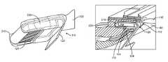
- FIG. 1illustrates a cable assembly according to an embodiment of the present invention. This figure, as with the other included figures, is shown for illustrative purposes and does not limit either the possible embodiments of the present invention or the claims.
- Connector insert portion 110may be configured to be inserted in receptacle 112 and may have a back that is arranged to fit approximately flush with an outside of an enclosure of electronic device 140 .
- Flexible cable 120may include a wider portion 122 .
- a pull tab 130may be included.
- Connector insert portion 110may be removed by pulling on pull tab 130 in a direction approximately orthogonal to a surface of the device enclosure for the electronic device 140 .
- connector insert portion 110may be arranged to be substantially flush with a surface of device enclosure 140 .
- Flexible cable 120may be routed underneath the electronic device and away from connector insert portion 110 .
- Pull tab 130may similarly be folded underneath the electronic device. This may provide a cable assembly that is not visible to a user who is viewing a screen on the electronic device. (In this figure, the screen may be facing downward towards a surface on which the electronic device is resting.)
- Traces or conductors in flexible cable 120may attach to contacts on connector insert portion 110 . These contacts may mate or form electrical connections with contacts in the connector receptacle 112 . In this way, power, data, and other signals may be transferred between the electronic device and one or more other electronic devices.
- flexible cable 120may be a flexible circuit board, though in other embodiments of the present invention it may be a ribbon cable or other type of flexible cable.
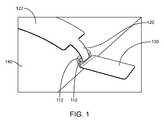
- FIG. 2illustrates a cable assembly according to an embodiment of the present invention.
- flexible cable 120may be wrapped at least partially around a cam or housing 210 .
- Cam or housing 210may include a first recess.
- One or more electronic components 220may be located in this recess. These components may include active devices, passive components, integrated circuits, relays, switches, microelectromechanical devices (MEMs), or other electronic or mechanical components. These components may include circuits for power, identification, authorization, theft-prevention, and other functions.
- MEMsmicroelectromechanical devices
- One or more contacts 124may be printed or otherwise formed on flexible cable 120 . These contacts may be printed on a first side of a first end portion of flexible cable 120 .
- the end portion of flexible cable 120may fit in a second recess in housing 210 .
- the first end portion of flexible cable 120may be glued, attached with adhesive or tape, or otherwise fixed to cam or housing 210 .
- Pull tab 130may be attached to insert portion 110 .
- pull tab 130may be glued, fixed with adhesive or tape, or otherwise attached to a first surface of flexible cable 120 .
- contacts 124may mate with corresponding contacts in a connector receptacle.
- flexible cable 120may be routed away and underneath the electronic device 140 such that the cable assembly is not visible to a user viewing a screen on the electronic device. An example is shown in the following figure.
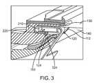
- FIG. 3illustrates a cable assembly inserted into an electronic device in accordance with an embodiment of the present invention.
- connector insert portion 110may include one or more electrical components 220 . These electrical components 220 may be housed in a recess in housing or cam 210 . Flexible cable 120 may be at least partially wrapped around cam or housing 210 . Pull tab 130 may be included to assist in the removal of connector insert portion 110 from electronic device 140 . Again, a rear of housing 210 may be arranged to fit substantially flush with an outside surface of an enclosure for electronic device 140 .
- One or more contacts 124 formed on flexible cable 120may mate with corresponding contacts 324 in the connector receptacle 112 . These connections may convey power, data, startup or configuration information, or other signals between this electronic device 140 and one or more other electronic devices. More specifically, contacts 124 may electrically connect to contacts at a distant end of flexible cable 120 . Contacts 124 and distant contacts (not shown) may electrically connect to each other or to components 220 .
- An example of one flexible cable 120is shown in the following figure.
- FIG. 4illustrates a flexible cable according to an embodiment of the present invention.
- This flexible cable 120may include a number of contacts 124 on an end portion of flexible cable 120 .
- Pull tab 130may also be attached to flexible cable 120 .
- Distant end portion 128may include a number of contacts 410 , 412 , 414 , and 416 . These contacts may convey data and power between electronic device 140 and one or other electronic devices.
- contacts 410may be a D ⁇ contact and contact 412 may be a D+ contact. These contacts may convey a Universal Serial Bus or other differential signal.
- Contact 414may be a VBUS contact, while contact 416 may be a ground contact.
- This second set of contactsmay supply power to electronic device 140 .
- a second side of flexible cable 120may include a contact area 420 , where one or more components may be attached. Traces may connect these components to one or more contacts 124 , as well as one or more contacts on distant end portion 128 .
- Connector assemblies consistent with embodiments of the present inventionmay be manufactured in various ways. An example is shown in the following figure.
- FIG. 5illustrates an intermediate step in the manufacturing of a cable assembly according to an embodiment of the present invention.
- One or more contacts 124may be formed on an end portion of flexible cable 120 .
- Pull tab 130may be attached to the top surface of flexible cable 120 .
- One or more electrical components 220may be attached to a second side of flexible cable 120 .
- a cam or housingmay be placed over electrical components 220 .
- Flexible cable 120may be at least partially wrapped around this cam or housing. An example of such a cam or housing is shown in the following figure.
- FIG. 6illustrates a cam or housing 210 according to an embodiment of the present invention.
- Cam or housing 210may include a first recess 610 .
- One or more electrical components 220may be located in first recess 610 .
- components 220may be sealed in a structure that is arranged to fit in first recess 610 . This may provide improved heat dissipation for components 220 .
- Cam or housing 210may protect electrical components 220 and provide a mechanical support for flexible cable 120 .
- Cam or housing 210may include a second recess 620 .
- An end portion of flexible cable 120 supporting contacts 124may be located in second recess 620 . This end portion may be glued, fixed with adhesive or tape, or otherwise secured to second recess 620 .
- a lip or edge around the recess 620may be used to secure the flexible cable 120 in place.
- Cam or housing 210may further include side indentations 630 , which may be grasped by a user during insertion into electronic device.
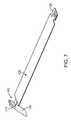
- FIG. 7illustrates a completed cable assembly according to an embodiment of the present invention.
- flexible cable 120may be at least partially wrapped around housing 210 to form connector insert portion 110 .
- Pull tab 130may be attached to connector insert portion 110 to assist in the removal of connector insert portion 110 from an electronic device.
- An end portion of flexible cable 120may support a number of contacts that may be electrically connected to contacts 124 on connector insert portion 110 and to one or more electrical components 220 inside housing 210 .
- FIG. 8illustrates a close-up view of a connector insert portion according to an embodiment of the present invention.
- a number of contacts 124may be located on an end portion of flexible cable 120 .
- Flexible cable 120may include a wider portion 122 .
- Flexible cable 120may be at least partially wrapped around housing 210 .
- a pull tab 130may be included.
- FIG. 9illustrates another close-up view of a connector insert portion according to an embodiment of the present invention.
- connector insert portion 110may include housing 210 .
- Pull tab 130may also be included.
Landscapes
- Engineering & Computer Science (AREA)
- Microelectronics & Electronic Packaging (AREA)
- Manufacturing & Machinery (AREA)
- Details Of Connecting Devices For Male And Female Coupling (AREA)
Abstract
Description
The amount of data transferred between electronic devices has grown tremendously the last several years. Large amounts of audio, streaming video, text, and other types of data content are now regularly transferred among desktop and portable computers, media devices, handheld media devices, displays, storage devices, and other types of electronic devices. Power supply voltages and ground may be transferred with this data.
Power and data may be conveyed over cables that may include wire conductors, fiber optic cables, or some combination of these or other conductors. Cable assemblies may include a connector insert at one or both ends of a cable, though cable assemblies may be connected or tethered to an electronic device in a dedicated manner. The connector inserts may be inserted into receptacles in the communicating electronic devices.
Many of these electronic devices are now being used in retail or other environments where customers and others interact directly with them. These devices may include touch or other types of screens that provide information about various items, products, or services. These screens may also allow users to explore databases to find further information, to request help, to place orders, or to interact in other ways.
Again, conventional cable assemblies include a connector insert at an end of a cable. The connector insert includes an insert portion to fit in a connector receptacle in an electronic device. A housing of the connector insert attaches to the insert portion and does not fit into the connector receptacle, but rather extends orthogonally to an exterior surface of the electronic device. The cable may extend from the housing, also in a direction orthogonal to the exterior surface of the electronic device.
While this housing may be very convenient in that is allows a user to easily insert and remove the connector insert, it may obstruct a user interacting with the electronic device. It may also consume space in a display area and have an undesirable appearance.
Thus, what is needed are cable assemblies including connector inserts that do not obstruct a user, do not consume space in a display area, and do not have an undesirable appearance.
Accordingly, embodiments of the present invention may provide cable assemblies that do not obstruct a user, do not consume space in a display area, and do not have an undesirable appearance. An illustrative embodiment of the present invention may provide a cable assembly including a connector insert to fit in a connector receptacle in an electronic device, where a back surface of the connector insert is substantially flush with an outside of an enclosure for the electronic device. One such illustrative embodiment of the present invention may provide a cable assembly that includes a flexible circuit board at least partially wrapped around a cam or housing. The flexible circuit board may be routed against an underside of the electronic device such that it does not obstruct a user, does not consume space in a display area, and does not have an undesirable appearance.
An illustrative embodiment of the present invention may include flexible cable at least partially wrapped around a cam or other housing. The flexible cable may be a flexible circuit board, ribbon connector, or other flexible cable. The flexible cable may be substantially flat to aid in keeping the cable out of sight of a user. The flexible cable may have an end portion, with a number of contacts printed or otherwise formed on a first side of the end portion of the flexible cable. The contacts may be electrically connected to conductors in the flexible cable.
One or more circuits or components may be attached to a second side of the flexible cable. In this way, the flexible cable may provide part of an enclosure for the circuits or components. These circuits may include active devices, passive components, integrated circuits, relays, switches, microelectromechanical devices (MEMs), or other electronic or mechanical components. These components may include circuits for power, identification, authorization, theft-prevention, and other functions. The components may be electrically connected to one or more conductors in the flexible cable and the contacts.
These components may be enclosed between the flexible cable and a housing, such as a cam or other type of housing. The housing may be metallic, though in various embodiments of the present invention it may be plastic, resin, ceramic, or other material or combination of these and other materials. The housing may have a first recess and the components may be located in the first recess. The housing may have a second recess and the end portion of the flexible cable may be located in the second recess. The housing or cam may help to enclose and protect the components, act as a plug head, and have a rear portion that conforms to an outside of a device enclosure.
The end portion of the flexible cable may be secured to the housing in the second recess. The end portion may be glued, taped, fixed with adhesive, or otherwise secured in place. The flexible cable may be wrapped at least partially around the housing or cam. This may allow contacts to be on a first side of the flexible cable and may allow the flexible cable to contact and enclose the components and exit the electronic device along its underside.
Again, the housing may have a back end arranged to be substantially flush with an outside of an enclosure for the electronic device. This, combined with the use of a flexible cable that may be discreetly routed, may provide a cable assembly that is unobtrusive, does not consume display area, and does not have an undesirable appearance. When a cable insert according to an embodiment of the present invention is inserted in an electronic device, the cable assembly may provide a connector insert and flexible cable that are not readily viewable by a user while that user is looking at a screen of the electronic device.
Contacts on the end portion of the flexible cable may engage or mate with connectors in the receptacle of the electronic device. Specifically, the housing may be arranged such that the contacts on the first side of the end portion of the flexible cable mate with contacts in the connector receptacle on the electronic device. These connections may be used to convey data, power, startup or configuration information, or other types of signals between the electronic device and one or more other electronic devices or networks.
While these cables may be useful in retail environments where they may rarely be disconnected, it may be desirable to disconnect them on occasion. It may be desirable that these cables not be removed by someone simply grabbing the flexible cable, as this may damage the cable assembly. Accordingly, embodiments of the present invention may include a pull tab for use in disconnecting and removing the cable assembly. This pull tab may be fixed using glue, tape, or adhesive, or otherwise attached to the first side of the flexible cable.
An illustrative embodiment of the present invention may provide a method of forming a cable assembly. This method may include forming a plurality of contacts on a first side at a first end portion of a flexible circuit board. A first component may be attached to a second side of a flexible circuit board. A housing may be aligned over the first component such that the first component fits in a first recess of the housing. A flexible circuit board may be at least partially wrapped around the housing. A pull tab may be attached to the first side of the flexible circuit board to enable the removal of the housing when it is inserted in a receptacle of an electronic device.
Embodiments of the present invention may be used in connector inserts and receptacles for cables that may connect to various types of devices, such as portable computing devices, tablets, desktop computers, laptops, all-in-one computers, cell phones, smart phones, media phones, storage devices, portable media players, navigation systems, monitors, power supplies, adapters, and chargers, and other devices. These connector inserts may provide pathways for signals and power compliant with various standards such as Universal Serial Bus (USB), a High-Definition Multimedia Interface (HDMI), Digital Visual Interface (DVI), power, Ethernet, DisplayPort, Thunderbolt, Lightning and other types of standard and non-standard interfaces.
Various embodiments of the present invention may incorporate one or more of these and the other features described herein. A better understanding of the nature and advantages of the present invention may be gained by reference to the following detailed description and the accompanying drawings.
This figure includes a cable assembly includingconnector insert portion 110 andflexible cable 120.Connector insert portion 110 may be configured to be inserted inreceptacle 112 and may have a back that is arranged to fit approximately flush with an outside of an enclosure ofelectronic device 140.Flexible cable 120 may include awider portion 122. To assist in removal ofconnector insert portion 110, apull tab 130 may be included.Connector insert portion 110 may be removed by pulling onpull tab 130 in a direction approximately orthogonal to a surface of the device enclosure for theelectronic device 140.
Again,connector insert portion 110 may be arranged to be substantially flush with a surface ofdevice enclosure 140.Flexible cable 120 may be routed underneath the electronic device and away fromconnector insert portion 110.Pull tab 130 may similarly be folded underneath the electronic device. This may provide a cable assembly that is not visible to a user who is viewing a screen on the electronic device. (In this figure, the screen may be facing downward towards a surface on which the electronic device is resting.)
Traces or conductors inflexible cable 120 may attach to contacts onconnector insert portion 110. These contacts may mate or form electrical connections with contacts in theconnector receptacle 112. In this way, power, data, and other signals may be transferred between the electronic device and one or more other electronic devices.
In this specific example,flexible cable 120 may be a flexible circuit board, though in other embodiments of the present invention it may be a ribbon cable or other type of flexible cable.
One ormore contacts 124 may be printed or otherwise formed onflexible cable 120. These contacts may be printed on a first side of a first end portion offlexible cable 120. The end portion offlexible cable 120 may fit in a second recess inhousing 210. The first end portion offlexible cable 120 may be glued, attached with adhesive or tape, or otherwise fixed to cam orhousing 210.Pull tab 130 may be attached to insertportion 110. For example,pull tab 130 may be glued, fixed with adhesive or tape, or otherwise attached to a first surface offlexible cable 120.
Again, whenconnector insert portion 110 is inserted into a receptacle,contacts 124 may mate with corresponding contacts in a connector receptacle. Also,flexible cable 120 may be routed away and underneath theelectronic device 140 such that the cable assembly is not visible to a user viewing a screen on the electronic device. An example is shown in the following figure.
One ormore contacts 124 formed onflexible cable 120 may mate withcorresponding contacts 324 in theconnector receptacle 112. These connections may convey power, data, startup or configuration information, or other signals between thiselectronic device 140 and one or more other electronic devices. More specifically,contacts 124 may electrically connect to contacts at a distant end offlexible cable 120.Contacts 124 and distant contacts (not shown) may electrically connect to each other or tocomponents 220. An example of oneflexible cable 120 is shown in the following figure.
Connector assemblies consistent with embodiments of the present invention may be manufactured in various ways. An example is shown in the following figure.
The above description of embodiments of the invention has been presented for the purposes of illustration and description. It is not intended to be exhaustive or to limit the invention to the precise form described, and many modifications and variations are possible in light of the teaching above. The embodiments were chosen and described in order to best explain the principles of the invention and its practical applications to thereby enable others skilled in the art to best utilize the invention in various embodiments and with various modifications as are suited to the particular use contemplated. Thus, it will be appreciated that the invention is intended to cover all modifications and equivalents within the scope of the following claims.
Claims (21)
1. A connector insert comprising:
a housing having a first recess;
a flexible circuit board at least partially wrapped around the housing;
an integrated circuit coupled to the flexible circuit board and located in the first recess; and
a plurality of contacts formed on the flexible circuit board and arranged to mate with a plurality of contacts in a receptacle of an electronic device.
2. The connector insert ofclaim 1 wherein the housing is metallic.
3. The connector insert ofclaim 1 wherein the plurality of contacts are located on a first end portion of the flexible circuit board, the housing further has a second recess, and the first end portion of the flexible circuit board is located in the second recess.
4. The connector insert ofclaim 1 further comprising a pull tab attached to the flexible circuit board.
5. The connector insert ofclaim 1 further comprising a pull tab attached to the connector insert.
6. A connector insert comprising:
a housing having a first recess and a second recess;
a flexible circuit board at least partially wrapped around the housing;
a component attached to the flexible circuit board and located in the first recess; and
a plurality of contacts located on a first end portion of the flexible circuit board and arranged to mate with a plurality of contacts in a receptacle of an electronic device, wherein the first end portion of the flexible circuit board is located in the second recess.
7. The connector insert ofclaim 6 wherein the component attached to the flexible circuit board comprises an integrated circuit.
8. The connector insert ofclaim 6 further comprising a pull tab attached to the flexible circuit board.
9. A method of manufacturing a connector insert comprising:
forming a plurality of contacts on a first side at a first end portion of a flexible circuit board, the plurality of contacts arranged to mate with a plurality of contacts in a receptacle of an electronic device;
attaching a first component to a second side of a flexible circuit board;
aligning a housing over the first component such that the first component fits in a first recess of the housing;
at least partially wrapping the flexible circuit board around the housing; and
fitting the first end portion of the flexible circuit board in a second recess in the housing.
10. The method ofclaim 9 further comprising:
attaching a pull tab to the first side of the flexible circuit board.
11. The method ofclaim 9 wherein the housing is metallic.
12. A cable assembly including a connector insert arranged to have a low-profile when inserted into an electronic device, the cable assembly comprising:
a housing having a first recess, the housing formed to fit in a receptacle in the electronic device and having a back surface arranged to be substantially flush with an outside surface of an enclosure for the electronic device;
a flexible cable at least partially wrapped around the housing; and
a plurality of contacts formed on a first end portion of the flexible cable and arranged to mate with a plurality of contacts in the receptacle, the first end portion located in the first receptacle.
13. The cable assembly ofclaim 12 wherein the housing is metallic.
14. The cable assembly ofclaim 12 wherein the housing comprises a second recess, and wherein an integrated circuit is attached to the flexible cable and is located in the first recess.
15. The cable assembly ofclaim 12 further comprising a pull tab attached to the flexible cable.
16. The cable assembly ofclaim 12 further comprising a pull tab attached to the connector insert.
17. The cable assembly ofclaim 12 wherein the flexible cable is a flexible circuit board.
18. A cable assembly including a connector insert arranged to have a low-profile when inserted into an electronic device, the cable assembly comprising:
a housing having a first recess, the housing formed to fit in a receptacle in the electronic device and having a back surface arranged to be substantially flush with an outside surface of an enclosure for the electronic device;
a flexible circuit board at least partially wrapped around the housing;
an integrated circuit attached to the flexible circuit board and located in the first recess; and
a plurality of contacts formed on the flexible circuit board and arranged to mate with a plurality of contacts in the receptacle.
19. The cable assembly ofclaim 18 wherein the plurality of contacts are located on a first end portion of the flexible circuit board.
20. The cable assembly ofclaim 19 wherein the housing includes a second recess and the first end portion of the flexible circuit board is located in the second recess.
21. The cable assembly ofclaim 20 further comprising a pull tab attached to the flexible circuit board.
Priority Applications (1)
| Application Number | Priority Date | Filing Date | Title |
|---|---|---|---|
| US14/195,823US9357654B2 (en) | 2014-03-03 | 2014-03-03 | Low-profile plug with cam and flexible circuit board |
Applications Claiming Priority (1)
| Application Number | Priority Date | Filing Date | Title |
|---|---|---|---|
| US14/195,823US9357654B2 (en) | 2014-03-03 | 2014-03-03 | Low-profile plug with cam and flexible circuit board |
Publications (2)
| Publication Number | Publication Date |
|---|---|
| US20150249297A1 US20150249297A1 (en) | 2015-09-03 |
| US9357654B2true US9357654B2 (en) | 2016-05-31 |
Family
ID=54007188
Family Applications (1)
| Application Number | Title | Priority Date | Filing Date |
|---|---|---|---|
| US14/195,823Expired - Fee RelatedUS9357654B2 (en) | 2014-03-03 | 2014-03-03 | Low-profile plug with cam and flexible circuit board |
Country Status (1)
| Country | Link |
|---|---|
| US (1) | US9357654B2 (en) |
Families Citing this family (3)
| Publication number | Priority date | Publication date | Assignee | Title |
|---|---|---|---|---|
| JP6187776B2 (en)* | 2014-12-12 | 2017-08-30 | カシオ計算機株式会社 | Electronics |
| CN107329446B (en)* | 2017-07-12 | 2020-09-01 | 长江重庆航运工程勘察设计院 | Method for monitoring and processing winding of buoy cable of navigation channel |
| CN210986561U (en)* | 2019-09-16 | 2020-07-10 | 惠州市荣光电子科技有限公司 | Multilayer printed flexible circuit board |
Citations (43)
| Publication number | Priority date | Publication date | Assignee | Title |
|---|---|---|---|---|
| JPS6356563A (en) | 1986-08-22 | 1988-03-11 | ダウ コ−ニング コ−ポレ−シヨン | Organosiloxane suppressor for hydrosilation and polyorganosiloxane composition containing same |
| JPH0395584A (en) | 1989-09-08 | 1991-04-19 | Canon Inc | Fixing roller |
| US20020024794A1 (en) | 2000-07-20 | 2002-02-28 | Yao-Chung Lin | Cradle |
| US20020142647A1 (en)* | 2001-02-22 | 2002-10-03 | Yazaki Corporation | Connector for flat circuit member |
| US6514089B2 (en)* | 2000-05-10 | 2003-02-04 | Sharp Kabushiki Kaisha | Terminal connecting device for flexible substrate |
| US6540559B1 (en) | 2001-09-28 | 2003-04-01 | Tyco Electronics Corporation | Connector with staggered contact pattern |
| US6584336B1 (en) | 1999-01-25 | 2003-06-24 | Masimo Corporation | Universal/upgrading pulse oximeter |
| US6685499B2 (en)* | 2000-09-12 | 2004-02-03 | Kel Corporation | Connector |
| US7125287B1 (en) | 2003-09-11 | 2006-10-24 | Super Talent Electronics, Inc. | Extended USB protocol plug and receptacle |
| US7293122B1 (en) | 2004-04-27 | 2007-11-06 | Apple Inc. | Connector interface system facilitating communication between a media player and accessories |
| US20070295982A1 (en) | 2006-06-27 | 2007-12-27 | Hana Micron Co., Ltd. | Micro universal serial bus memory package and manufacturing method the same |
| US7442057B2 (en) | 2006-10-12 | 2008-10-28 | Hon Hai Precision Ind. Co., Ltd. | MIMO RF connector assembly |
| US20080268711A1 (en) | 2007-04-24 | 2008-10-30 | Matsushita Electric Works, Ltd. | Connector and connector connecting body |
| JP2009048978A (en) | 2007-08-23 | 2009-03-05 | Hirose Electric Co Ltd | Connector with buckling prevention function |
| US20090061678A1 (en) | 2007-09-04 | 2009-03-05 | Apple Inc. | Smart Cables |
| US20090093136A1 (en) | 2003-12-02 | 2009-04-09 | Super Talent Electronics, Inc. | Single Shot Molding Method For COB USB/EUSB Devices With Contact Pad Ribs |
| US7540788B2 (en) | 2007-01-05 | 2009-06-02 | Apple Inc. | Backward compatible connector system |
| US7544066B1 (en) | 2008-03-10 | 2009-06-09 | Apple Inc. | Electrical connector with flexible interconnect |
| US20090179501A1 (en) | 2008-01-04 | 2009-07-16 | Mitch Randall | Device cover with embedded power receiver |
| US20090236140A1 (en) | 2007-10-12 | 2009-09-24 | Mitch Randall | Wireless power receiver module |
| US7594817B2 (en)* | 2008-02-15 | 2009-09-29 | Sony Ericsson Mobile Communications Ab | Electrical flex connector for mounting on a printed circuit board |
| US20090247017A1 (en) | 2008-04-01 | 2009-10-01 | Hon Hai Precision Ind. Co., Ltd. | Electrical connector with dual-interface |
| US7627343B2 (en) | 2003-04-25 | 2009-12-01 | Apple Inc. | Media player system |
| US7684186B2 (en) | 2007-12-28 | 2010-03-23 | Clientron Corp. | Security mechanism of a base |
| US20100081337A1 (en) | 2008-09-26 | 2010-04-01 | Apple Inc. | Adapter |
| USRE41224E1 (en) | 2003-04-30 | 2010-04-13 | Japan Aviation Electronics Industry, Limited | Connector |
| CN101740961A (en) | 2008-11-10 | 2010-06-16 | 富士康(昆山)电脑接插件有限公司 | Electrical Connector Assembly |
| US20100255712A1 (en) | 2009-04-02 | 2010-10-07 | Hon Hai Precision Industry Co., Ltd. | Cable assembly with improved coupling structure |
| US7832645B2 (en) | 2006-04-10 | 2010-11-16 | Kingston Technology Corporation | Flash memory card expander |
| US7909652B2 (en) | 2008-08-11 | 2011-03-22 | Hon Hai Precision Ind. Co., Ltd. | Electrical connector with two grooves dividing contacts |
| US7918689B2 (en) | 2008-09-30 | 2011-04-05 | Apple Inc. | Reduced size multi-pin male plug connector |
| US7963809B2 (en) | 2008-01-06 | 2011-06-21 | Apple Inc. | Microdvi connector |
| US7988496B2 (en) | 2009-09-04 | 2011-08-02 | Hon Hai Precision Ind. Co., Ltd. | Electrical connector with improved elasticity contacts |
| US20110218414A1 (en) | 2003-08-22 | 2011-09-08 | Dexcom, Inc. | Systems and methods for processing analyte sensor data |
| US20110230076A1 (en)* | 2008-12-04 | 2011-09-22 | Chin Hua Lim | Method, system and devices for interconnecting a plurality of devices |
| US8096815B2 (en) | 2009-11-02 | 2012-01-17 | Hon Hai Precision Ind. Co., Ltd. | Reliable electrical connection electrical connector assembly |
| US20120015544A1 (en) | 2010-07-13 | 2012-01-19 | Hon Hai Precision Industry Co., Ltd. | Electrical connector assembly having engaging means for providing holding force |
| US8113865B1 (en) | 2010-08-27 | 2012-02-14 | Cheng Uei Precision Industry Co., Ltd. | Plug connector |
| US8118497B2 (en) | 2008-12-23 | 2012-02-21 | Hon Hai Precision Ind. Co., Ltd. | Connector utilized for different kinds of signal transmition |
| DE102012208328A1 (en) | 2011-05-20 | 2012-11-22 | Apple Inc. | Male connector with low profile |
| US8342890B2 (en) | 2010-03-31 | 2013-01-01 | Hon Hai Precision Ind. Co., Ltd. | Low profile electrical connector with two rows of contacts |
| US8485851B2 (en) | 2009-03-24 | 2013-07-16 | Hosiden Corporation | Connector |
| US8532727B2 (en) | 1999-01-25 | 2013-09-10 | Masimo Corporation | Dual-mode pulse oximeter |
- 2014
- 2014-03-03USUS14/195,823patent/US9357654B2/ennot_activeExpired - Fee Related
Patent Citations (55)
| Publication number | Priority date | Publication date | Assignee | Title |
|---|---|---|---|---|
| JPS6356563A (en) | 1986-08-22 | 1988-03-11 | ダウ コ−ニング コ−ポレ−シヨン | Organosiloxane suppressor for hydrosilation and polyorganosiloxane composition containing same |
| JPH0395584A (en) | 1989-09-08 | 1991-04-19 | Canon Inc | Fixing roller |
| US8532727B2 (en) | 1999-01-25 | 2013-09-10 | Masimo Corporation | Dual-mode pulse oximeter |
| US6584336B1 (en) | 1999-01-25 | 2003-06-24 | Masimo Corporation | Universal/upgrading pulse oximeter |
| US6514089B2 (en)* | 2000-05-10 | 2003-02-04 | Sharp Kabushiki Kaisha | Terminal connecting device for flexible substrate |
| US20020024794A1 (en) | 2000-07-20 | 2002-02-28 | Yao-Chung Lin | Cradle |
| US6685499B2 (en)* | 2000-09-12 | 2004-02-03 | Kel Corporation | Connector |
| US20020142647A1 (en)* | 2001-02-22 | 2002-10-03 | Yazaki Corporation | Connector for flat circuit member |
| US6540559B1 (en) | 2001-09-28 | 2003-04-01 | Tyco Electronics Corporation | Connector with staggered contact pattern |
| US7627343B2 (en) | 2003-04-25 | 2009-12-01 | Apple Inc. | Media player system |
| USRE41224E1 (en) | 2003-04-30 | 2010-04-13 | Japan Aviation Electronics Industry, Limited | Connector |
| US20110218414A1 (en) | 2003-08-22 | 2011-09-08 | Dexcom, Inc. | Systems and methods for processing analyte sensor data |
| US7125287B1 (en) | 2003-09-11 | 2006-10-24 | Super Talent Electronics, Inc. | Extended USB protocol plug and receptacle |
| US20090093136A1 (en) | 2003-12-02 | 2009-04-09 | Super Talent Electronics, Inc. | Single Shot Molding Method For COB USB/EUSB Devices With Contact Pad Ribs |
| US8102657B2 (en) | 2003-12-02 | 2012-01-24 | Super Talent Electronics, Inc. | Single shot molding method for COB USB/EUSB devices with contact pad ribs |
| US7293122B1 (en) | 2004-04-27 | 2007-11-06 | Apple Inc. | Connector interface system facilitating communication between a media player and accessories |
| US7832645B2 (en) | 2006-04-10 | 2010-11-16 | Kingston Technology Corporation | Flash memory card expander |
| US20070295982A1 (en) | 2006-06-27 | 2007-12-27 | Hana Micron Co., Ltd. | Micro universal serial bus memory package and manufacturing method the same |
| US7709946B2 (en) | 2006-06-27 | 2010-05-04 | Hana Micron Co., Ltd. | Micro universal serial bus (USB) memory package |
| US7442057B2 (en) | 2006-10-12 | 2008-10-28 | Hon Hai Precision Ind. Co., Ltd. | MIMO RF connector assembly |
| US7540788B2 (en) | 2007-01-05 | 2009-06-02 | Apple Inc. | Backward compatible connector system |
| US20080268711A1 (en) | 2007-04-24 | 2008-10-30 | Matsushita Electric Works, Ltd. | Connector and connector connecting body |
| JP2009048978A (en) | 2007-08-23 | 2009-03-05 | Hirose Electric Co Ltd | Connector with buckling prevention function |
| US20090061678A1 (en) | 2007-09-04 | 2009-03-05 | Apple Inc. | Smart Cables |
| US20090236140A1 (en) | 2007-10-12 | 2009-09-24 | Mitch Randall | Wireless power receiver module |
| US7684186B2 (en) | 2007-12-28 | 2010-03-23 | Clientron Corp. | Security mechanism of a base |
| US20090179501A1 (en) | 2008-01-04 | 2009-07-16 | Mitch Randall | Device cover with embedded power receiver |
| US7963809B2 (en) | 2008-01-06 | 2011-06-21 | Apple Inc. | Microdvi connector |
| US7594817B2 (en)* | 2008-02-15 | 2009-09-29 | Sony Ericsson Mobile Communications Ab | Electrical flex connector for mounting on a printed circuit board |
| US7544066B1 (en) | 2008-03-10 | 2009-06-09 | Apple Inc. | Electrical connector with flexible interconnect |
| US20090247017A1 (en) | 2008-04-01 | 2009-10-01 | Hon Hai Precision Ind. Co., Ltd. | Electrical connector with dual-interface |
| US7909652B2 (en) | 2008-08-11 | 2011-03-22 | Hon Hai Precision Ind. Co., Ltd. | Electrical connector with two grooves dividing contacts |
| US20100081337A1 (en) | 2008-09-26 | 2010-04-01 | Apple Inc. | Adapter |
| US7918689B2 (en) | 2008-09-30 | 2011-04-05 | Apple Inc. | Reduced size multi-pin male plug connector |
| CN101740961A (en) | 2008-11-10 | 2010-06-16 | 富士康(昆山)电脑接插件有限公司 | Electrical Connector Assembly |
| US20110230076A1 (en)* | 2008-12-04 | 2011-09-22 | Chin Hua Lim | Method, system and devices for interconnecting a plurality of devices |
| US8118497B2 (en) | 2008-12-23 | 2012-02-21 | Hon Hai Precision Ind. Co., Ltd. | Connector utilized for different kinds of signal transmition |
| US8485851B2 (en) | 2009-03-24 | 2013-07-16 | Hosiden Corporation | Connector |
| US20100255712A1 (en) | 2009-04-02 | 2010-10-07 | Hon Hai Precision Industry Co., Ltd. | Cable assembly with improved coupling structure |
| US7988496B2 (en) | 2009-09-04 | 2011-08-02 | Hon Hai Precision Ind. Co., Ltd. | Electrical connector with improved elasticity contacts |
| US8096815B2 (en) | 2009-11-02 | 2012-01-17 | Hon Hai Precision Ind. Co., Ltd. | Reliable electrical connection electrical connector assembly |
| US8342890B2 (en) | 2010-03-31 | 2013-01-01 | Hon Hai Precision Ind. Co., Ltd. | Low profile electrical connector with two rows of contacts |
| US20120015544A1 (en) | 2010-07-13 | 2012-01-19 | Hon Hai Precision Industry Co., Ltd. | Electrical connector assembly having engaging means for providing holding force |
| US8113865B1 (en) | 2010-08-27 | 2012-02-14 | Cheng Uei Precision Industry Co., Ltd. | Plug connector |
| CN102856749A (en) | 2011-05-20 | 2013-01-02 | 苹果公司 | Low profile male connector |
| WO2012162255A1 (en) | 2011-05-20 | 2012-11-29 | Apple Inc. | Low profile male connector |
| JP2012243774A (en) | 2011-05-20 | 2012-12-10 | Apple Inc | Low profile male connector |
| DE102012208328A1 (en) | 2011-05-20 | 2012-11-22 | Apple Inc. | Male connector with low profile |
| US20120295487A1 (en) | 2011-05-20 | 2012-11-22 | Apple Inc. | Low Profile Male Connector |
| US8414337B2 (en) | 2011-05-20 | 2013-04-09 | Apple Inc. | Low profile male connector |
| GB2491243A (en) | 2011-05-20 | 2012-11-28 | Apple Inc | Connector |
| US20130217269A1 (en) | 2011-05-20 | 2013-08-22 | Apple Inc. | Low profile male connector |
| FR2975539A1 (en) | 2011-05-20 | 2012-11-23 | Apple Inc | MALE CONNECTOR WITH LOW PROFILE |
| US8727812B2 (en) | 2011-05-20 | 2014-05-20 | Apple Inc. | Low profile male connector |
| US20140256186A1 (en) | 2011-05-20 | 2014-09-11 | Apple Inc. | Low profile male connector |
Also Published As
| Publication number | Publication date |
|---|---|
| US20150249297A1 (en) | 2015-09-03 |
Similar Documents
| Publication | Publication Date | Title |
|---|---|---|
| US10862248B2 (en) | Durable connector receptacles with reinforced tongue and ground contacts | |
| US10355419B2 (en) | Connector receptacle having a shield | |
| US9660389B2 (en) | Additional ground paths for connectors having reduced pin counts | |
| AU2013205683B2 (en) | USB3 connector | |
| US8920197B2 (en) | Connector receptacle with ground contact having split rear extensions | |
| US7955124B2 (en) | Cable connector assembly with an extra connector to supply power | |
| US20130288537A1 (en) | Usb3 connector | |
| US9843133B2 (en) | Connector retention features for reduced wear | |
| US20170069995A1 (en) | Surface connector with silicone spring member | |
| EP3142198B1 (en) | Adapter | |
| US9357654B2 (en) | Low-profile plug with cam and flexible circuit board | |
| US8435050B2 (en) | USB connector having vertical to horizontal conversion contacts | |
| US9142908B2 (en) | Low profile male connector | |
| US20170070007A1 (en) | Pin alignment and protection in combined connector receptacles | |
| US9118122B2 (en) | Assembly of an electrical connector and a cable unit and electronic device including the assembly | |
| US9917407B1 (en) | High-definition multimedia interface (HDMI) cable integrated with a media device | |
| US11349249B2 (en) | Circular connector in integrated in hinge | |
| US20140162501A1 (en) | Connector | |
| US9077121B2 (en) | Pins for connector alignment | |
| US20250087953A1 (en) | Space-saving rigid-flex structures | |
| US8784135B1 (en) | Compression plug for portable electronics | |
| CN103135668A (en) | Panel personal computer (PPC) |
Legal Events
| Date | Code | Title | Description |
|---|---|---|---|
| AS | Assignment | Owner name:APPLE INC., CALIFORNIA Free format text:ASSIGNMENT OF ASSIGNORS INTEREST;ASSIGNORS:NG, NATHAN;YUAN, PAUL;KIM, MIN CHUL;REEL/FRAME:032386/0081 Effective date:20140303 | |
| ZAAA | Notice of allowance and fees due | Free format text:ORIGINAL CODE: NOA | |
| ZAAB | Notice of allowance mailed | Free format text:ORIGINAL CODE: MN/=. | |
| STCF | Information on status: patent grant | Free format text:PATENTED CASE | |
| MAFP | Maintenance fee payment | Free format text:PAYMENT OF MAINTENANCE FEE, 4TH YEAR, LARGE ENTITY (ORIGINAL EVENT CODE: M1551); ENTITY STATUS OF PATENT OWNER: LARGE ENTITY Year of fee payment:4 | |
| FEPP | Fee payment procedure | Free format text:MAINTENANCE FEE REMINDER MAILED (ORIGINAL EVENT CODE: REM.); ENTITY STATUS OF PATENT OWNER: LARGE ENTITY | |
| STCH | Information on status: patent discontinuation | Free format text:PATENT EXPIRED DUE TO NONPAYMENT OF MAINTENANCE FEES UNDER 37 CFR 1.362 | |
| FP | Lapsed due to failure to pay maintenance fee | Effective date:20240531 |