US9353916B2 - Elongated LED luminaire and associated methods - Google Patents
Elongated LED luminaire and associated methodsDownload PDFInfo
- Publication number
- US9353916B2 US9353916B2US14/844,353US201514844353AUS9353916B2US 9353916 B2US9353916 B2US 9353916B2US 201514844353 AUS201514844353 AUS 201514844353AUS 9353916 B2US9353916 B2US 9353916B2
- Authority
- US
- United States
- Prior art keywords
- light
- light guide
- source
- lamp
- luminaire
- Prior art date
- Legal status (The legal status is an assumption and is not a legal conclusion. Google has not performed a legal analysis and makes no representation as to the accuracy of the status listed.)
- Expired - Fee Related
Links
- 238000000034methodMethods0.000titledescription21
- 238000004891communicationMethods0.000claimsabstractdescription16
- 230000008859changeEffects0.000claimsabstractdescription15
- 239000000463materialSubstances0.000claimsdescription27
- 238000006243chemical reactionMethods0.000claimsdescription11
- 238000009792diffusion processMethods0.000claimsdescription5
- 238000005286illuminationMethods0.000description8
- 238000009434installationMethods0.000description7
- 230000008901benefitEffects0.000description6
- 238000005516engineering processMethods0.000description6
- 238000004519manufacturing processMethods0.000description6
- 238000013461designMethods0.000description5
- 239000000853adhesiveSubstances0.000description4
- 230000001070adhesive effectEffects0.000description4
- 238000009826distributionMethods0.000description4
- 239000011521glassSubstances0.000description4
- 239000003292glueSubstances0.000description4
- 238000003466weldingMethods0.000description4
- 229910052782aluminiumInorganic materials0.000description3
- XAGFODPZIPBFFR-UHFFFAOYSA-NaluminiumChemical compound[Al]XAGFODPZIPBFFR-UHFFFAOYSA-N0.000description3
- 230000000712assemblyEffects0.000description3
- 238000000429assemblyMethods0.000description3
- 238000000576coating methodMethods0.000description3
- 239000004020conductorSubstances0.000description3
- 238000001816coolingMethods0.000description3
- QSHDDOUJBYECFT-UHFFFAOYSA-NmercuryChemical compound[Hg]QSHDDOUJBYECFT-UHFFFAOYSA-N0.000description3
- 238000009420retrofittingMethods0.000description3
- 239000011248coating agentSubstances0.000description2
- 230000003750conditioning effectEffects0.000description2
- 230000003247decreasing effectEffects0.000description2
- 239000006185dispersionSubstances0.000description2
- 238000005265energy consumptionMethods0.000description2
- 238000007726management methodMethods0.000description2
- 229910052753mercuryInorganic materials0.000description2
- 238000012986modificationMethods0.000description2
- 230000004048modificationEffects0.000description2
- NJPPVKZQTLUDBO-UHFFFAOYSA-NnovaluronChemical compoundC1=C(Cl)C(OC(F)(F)C(OC(F)(F)F)F)=CC=C1NC(=O)NC(=O)C1=C(F)C=CC=C1FNJPPVKZQTLUDBO-UHFFFAOYSA-N0.000description2
- 229910000838Al alloyInorganic materials0.000description1
- RYGMFSIKBFXOCR-UHFFFAOYSA-NCopperChemical compound[Cu]RYGMFSIKBFXOCR-UHFFFAOYSA-N0.000description1
- VYPSYNLAJGMNEJ-UHFFFAOYSA-NSilicium dioxideChemical compoundO=[Si]=OVYPSYNLAJGMNEJ-UHFFFAOYSA-N0.000description1
- 230000004075alterationEffects0.000description1
- 229910000323aluminium silicateInorganic materials0.000description1
- 238000003491arrayMethods0.000description1
- 239000005385borate glassSubstances0.000description1
- -1but not limited toSubstances0.000description1
- WUKWITHWXAAZEY-UHFFFAOYSA-Lcalcium difluorideChemical compound[F-].[F-].[Ca+2]WUKWITHWXAAZEY-UHFFFAOYSA-L0.000description1
- 229910021387carbon allotropeInorganic materials0.000description1
- 238000005266castingMethods0.000description1
- 239000000919ceramicSubstances0.000description1
- 239000005387chalcogenide glassSubstances0.000description1
- 239000003086colorantSubstances0.000description1
- 239000002131composite materialSubstances0.000description1
- 239000000470constituentSubstances0.000description1
- 229910052802copperInorganic materials0.000description1
- 239000010949copperSubstances0.000description1
- 230000009977dual effectEffects0.000description1
- 230000000694effectsEffects0.000description1
- 230000005611electricityEffects0.000description1
- 230000002708enhancing effectEffects0.000description1
- 230000007613environmental effectEffects0.000description1
- 239000005308flint glassSubstances0.000description1
- 239000012530fluidSubstances0.000description1
- 239000005383fluoride glassSubstances0.000description1
- 239000010436fluoriteSubstances0.000description1
- 239000005350fused silica glassSubstances0.000description1
- 230000005484gravityEffects0.000description1
- 239000002920hazardous wasteSubstances0.000description1
- 239000005355lead glassSubstances0.000description1
- 238000012423maintenanceMethods0.000description1
- 229910052751metalInorganic materials0.000description1
- 239000002184metalSubstances0.000description1
- 229910001092metal group alloyInorganic materials0.000description1
- 150000002739metalsChemical class0.000description1
- 238000000465mouldingMethods0.000description1
- 239000012811non-conductive materialSubstances0.000description1
- 238000009828non-uniform distributionMethods0.000description1
- 230000003287optical effectEffects0.000description1
- 239000005365phosphate glassSubstances0.000description1
- 229920000515polycarbonatePolymers0.000description1
- 239000004417polycarbonateSubstances0.000description1
- 229920000642polymerPolymers0.000description1
- 229910052573porcelainInorganic materials0.000description1
- 230000008569processEffects0.000description1
- 230000002035prolonged effectEffects0.000description1
- 230000005855radiationEffects0.000description1
- 230000001105regulatory effectEffects0.000description1
- 230000004044responseEffects0.000description1
- 239000005361soda-lime glassSubstances0.000description1
- 229920001169thermoplasticPolymers0.000description1
- 239000004416thermosoftening plasticSubstances0.000description1
- 239000011800void materialSubstances0.000description1
- 239000002699waste materialSubstances0.000description1
Images


Classifications
- F21K9/175—
- F—MECHANICAL ENGINEERING; LIGHTING; HEATING; WEAPONS; BLASTING
- F21—LIGHTING
- F21K—NON-ELECTRIC LIGHT SOURCES USING LUMINESCENCE; LIGHT SOURCES USING ELECTROCHEMILUMINESCENCE; LIGHT SOURCES USING CHARGES OF COMBUSTIBLE MATERIAL; LIGHT SOURCES USING SEMICONDUCTOR DEVICES AS LIGHT-GENERATING ELEMENTS; LIGHT SOURCES NOT OTHERWISE PROVIDED FOR
- F21K9/00—Light sources using semiconductor devices as light-generating elements, e.g. using light-emitting diodes [LED] or lasers
- F21K9/20—Light sources comprising attachment means
- F21K9/27—Retrofit light sources for lighting devices with two fittings for each light source, e.g. for substitution of fluorescent tubes
- F21K9/50—
- F21K9/52—
- F—MECHANICAL ENGINEERING; LIGHTING; HEATING; WEAPONS; BLASTING
- F21—LIGHTING
- F21K—NON-ELECTRIC LIGHT SOURCES USING LUMINESCENCE; LIGHT SOURCES USING ELECTROCHEMILUMINESCENCE; LIGHT SOURCES USING CHARGES OF COMBUSTIBLE MATERIAL; LIGHT SOURCES USING SEMICONDUCTOR DEVICES AS LIGHT-GENERATING ELEMENTS; LIGHT SOURCES NOT OTHERWISE PROVIDED FOR
- F21K9/00—Light sources using semiconductor devices as light-generating elements, e.g. using light-emitting diodes [LED] or lasers
- F21K9/60—Optical arrangements integrated in the light source, e.g. for improving the colour rendering index or the light extraction
- F21K9/61—Optical arrangements integrated in the light source, e.g. for improving the colour rendering index or the light extraction using light guides
- F—MECHANICAL ENGINEERING; LIGHTING; HEATING; WEAPONS; BLASTING
- F21—LIGHTING
- F21V—FUNCTIONAL FEATURES OR DETAILS OF LIGHTING DEVICES OR SYSTEMS THEREOF; STRUCTURAL COMBINATIONS OF LIGHTING DEVICES WITH OTHER ARTICLES, NOT OTHERWISE PROVIDED FOR
- F21V17/00—Fastening of component parts of lighting devices, e.g. shades, globes, refractors, reflectors, filters, screens, grids or protective cages
- F21V17/06—Fastening of component parts of lighting devices, e.g. shades, globes, refractors, reflectors, filters, screens, grids or protective cages the fastening being onto or by the lampholder
- F—MECHANICAL ENGINEERING; LIGHTING; HEATING; WEAPONS; BLASTING
- F21—LIGHTING
- F21V—FUNCTIONAL FEATURES OR DETAILS OF LIGHTING DEVICES OR SYSTEMS THEREOF; STRUCTURAL COMBINATIONS OF LIGHTING DEVICES WITH OTHER ARTICLES, NOT OTHERWISE PROVIDED FOR
- F21V29/00—Protecting lighting devices from thermal damage; Cooling or heating arrangements specially adapted for lighting devices or systems
- F21V29/50—Cooling arrangements
- F21V29/70—Cooling arrangements characterised by passive heat-dissipating elements, e.g. heat-sinks
- F—MECHANICAL ENGINEERING; LIGHTING; HEATING; WEAPONS; BLASTING
- F21—LIGHTING
- F21K—NON-ELECTRIC LIGHT SOURCES USING LUMINESCENCE; LIGHT SOURCES USING ELECTROCHEMILUMINESCENCE; LIGHT SOURCES USING CHARGES OF COMBUSTIBLE MATERIAL; LIGHT SOURCES USING SEMICONDUCTOR DEVICES AS LIGHT-GENERATING ELEMENTS; LIGHT SOURCES NOT OTHERWISE PROVIDED FOR
- F21K9/00—Light sources using semiconductor devices as light-generating elements, e.g. using light-emitting diodes [LED] or lasers
- F21K9/90—Methods of manufacture
- F21Y2101/02—
- F—MECHANICAL ENGINEERING; LIGHTING; HEATING; WEAPONS; BLASTING
- F21—LIGHTING
- F21Y—INDEXING SCHEME ASSOCIATED WITH SUBCLASSES F21K, F21L, F21S and F21V, RELATING TO THE FORM OR THE KIND OF THE LIGHT SOURCES OR OF THE COLOUR OF THE LIGHT EMITTED
- F21Y2115/00—Light-generating elements of semiconductor light sources
- F21Y2115/10—Light-emitting diodes [LED]
- Y—GENERAL TAGGING OF NEW TECHNOLOGICAL DEVELOPMENTS; GENERAL TAGGING OF CROSS-SECTIONAL TECHNOLOGIES SPANNING OVER SEVERAL SECTIONS OF THE IPC; TECHNICAL SUBJECTS COVERED BY FORMER USPC CROSS-REFERENCE ART COLLECTIONS [XRACs] AND DIGESTS
- Y02—TECHNOLOGIES OR APPLICATIONS FOR MITIGATION OR ADAPTATION AGAINST CLIMATE CHANGE
- Y02B—CLIMATE CHANGE MITIGATION TECHNOLOGIES RELATED TO BUILDINGS, e.g. HOUSING, HOUSE APPLIANCES OR RELATED END-USER APPLICATIONS
- Y02B20/00—Energy efficient lighting technologies, e.g. halogen lamps or gas discharge lamps
- Y02B20/30—Semiconductor lamps, e.g. solid state lamps [SSL] light emitting diodes [LED] or organic LED [OLED]
- Y02B20/386—
- Y—GENERAL TAGGING OF NEW TECHNOLOGICAL DEVELOPMENTS; GENERAL TAGGING OF CROSS-SECTIONAL TECHNOLOGIES SPANNING OVER SEVERAL SECTIONS OF THE IPC; TECHNICAL SUBJECTS COVERED BY FORMER USPC CROSS-REFERENCE ART COLLECTIONS [XRACs] AND DIGESTS
- Y10—TECHNICAL SUBJECTS COVERED BY FORMER USPC
- Y10T—TECHNICAL SUBJECTS COVERED BY FORMER US CLASSIFICATION
- Y10T29/00—Metal working
- Y10T29/49—Method of mechanical manufacture
- Y10T29/49002—Electrical device making
- Y10T29/49117—Conductor or circuit manufacturing
Definitions
- the present inventionrelates generally to the field of lighting and, in particular, to luminaires used to replace fluorescent lamps, and associated methods.
- a fluorescent lampalso called a fluorescent tube
- Linear fluorescent lampsare routinely used in commercial or institutional buildings, and are commonly installed in troffer light fixtures (recessed troughs installed in a ceiling) and pendant light fixtures (housings suspended from a ceiling by a chain or pipe).
- Fluorescent lampshave been steadily replacing incandescent lamps in many lighting applications. Compared to an incandescent lamp, a fluorescent lamp converts electrical power into useful light more efficiently, delivers a significantly longer useful life, and presents a more diffuse and physically larger light source.
- fluorescent lamp technologyhas disadvantages.
- a fluorescent lampis typically more expensive to install and operate than an incandescent lamp because the fluorescent lamp requires a ballast to regulate the electrical current.
- Fluorescent light fixturescannot be connected directly to dimmer switches intended for incandescent lamps, but instead require a compatible dimming ballast.
- the performance of fluorescent lampsmay be negatively impacted by environmental conditions such as frequent switching and operating temperatures. Many fluorescent lamps have poor color temperature, resulting in a less aesthetically pleasing light.
- Some fluorescent lampsare characterized by prolonged warm-up times, requiring up to three minutes before maximum light output is achieved. Also, if a fluorescent lamp that uses mercury vapor is broken, a small amount of mercury (classified as hazardous waste) can contaminate the surrounding environment.
- LEDslight-emitting diodes
- Digital lighting technologiessuch as light-emitting diodes (LEDs) offer significant advantages over traditional linear fluorescent lamps. These include, but are not limited to, better lighting quality, longer operating life, and lower energy consumption. Increasingly, LEDs are being designed to have desirable color temperatures. Moreover, LEDs do not contain mercury. Consequently, a market exists for LED-based retrofit alternatives to legacy lighting fixtures that use fluorescent lamps.
- a number of installation challenges and costsare associated with replacing linear fluorescent lamps with LED illumination devices. The challenges, which are understood by those skilled in the art, include light production, thermal management, and installation ease.
- the costswhich are similarly understood by those skilled in the art, typically stem from a need to replace or reconfigure a troffer or pendant fixture that is configured to support fluorescent lamps to instead support LEDs.
- LEDshave a directional light output. Consequently, employing LEDs to produce light distribution properties approximating or equaling the light dispersion properties of traditional lamps may require the costly and labor-intensive replacement or reconfiguration of the host light fixture, and/or the expensive and complexity-introducing design of LED-based solutions that minimize the installation impact to the host light fixture. Often material and manufacturing costs are lost in this trade off.
- Heat sinksare well known in the art and have been effectively used to provide cooling capacity, thus maintaining an LED-based light bulb within a desirable operating temperature. However, heat sinks can sometimes negatively impact the light distribution properties of the light fixture, resulting in non-uniform distribution of light about the fixture. Heat sink designs also may add to the weight and/or profile of an illumination device, thereby complicating installation, and also may limit available space for other components needed for delivering light.
- LED-based lighting solutionsmay be complicated by the need to adapt LED-based devices to meet legacy form standards. For example, in a commercial lighting system retrofit, disposal of a replaced fluorescent lamp's fixture housing often is impractical. Consequently, retrofit lamps often are designed to adapt to a legacy fluorescent fixture, both functionally and aesthetically. Also, power supply requirements of LED-based lighting systems can complicate installation of LEDs as a retrofit to existing light fixtures. LEDs are low-voltage light sources that require constant DC voltage or current to operate optimally, and therefore must be carefully regulated. Too little current and voltage may result in little or no light. Too much current and voltage can damage the light-emitting junction of the LED.
- LEDsare commonly supplemented with individual power adapters to convert AC power to the proper DC voltage, and to regulate the current flowing through during operation to protect the LEDs from line-voltage fluctuations.
- the lighting industryis experiencing advancements in LED applications, some of which may be pertinent to certain aspects of replacing linear fluorescent lamps.
- U.S. Pat. No. 6,739,734 to Hulgandiscloses a method of retrofitting a fluorescent light fixture (e.g., four foot T12or T8 lamps) with LED-based luminaires without requiring removal of the fixture housing. However, rather than maintain existing circuitry, the fixture is stripped not only of its fluorescent lamps but also of its wireway cover and ballast(s).
- U.S. Published Patent Application No. 2010/0033095 by Sadwickdiscloses an apparatus for replacing a fluorescent lamp that includes an electrical connector adapted to maintain the existing circuitry of the fixture, including the fluorescent ballast. A voltage converter, direct current (DC) rectifier, and LED light source included in the apparatus simulate the behavior of a fluorescent lamp in response to signals from the fixture's existing circuitry.
- the referencedefines a lamp housing physically configured as a prosthetic replacement for a fluorescent lamp in the fixture, rather than as a less expensive non-tubular light-directing structure.
- the Cross referencedefines a cylindrical elongated transparent envelope holding at least one serial string of LEDs along its length.
- the Lodhie referencediscloses a substantially transparent hollow cylinder containing multiple LEDs arranged to form two LED arrays, and mounted along opposite sides of a substantially planar printed circuit board (PCB).
- PCBsubstantially planar printed circuit board
- the Farmer referencealso defines a tubular structure, but employs one or more side light LEDs combined with gradient optics to achieve a selected emitted light intensity variation across the surface of the tube.
- all three referencesdefine a lamp housing physically configured as a prosthetic replacement for a fluorescent lamp in the fixture, rather than as a less expensive non-tubular light-directing structure.
- the luminairemay comprise a lamp, the lamp comprising an outer structure, a light source that may be configured to emit a source light and carried by the outer structure, a middle structure connected to the outer structure, and a bi-pin base connected to the middle structure.
- the luminairemay comprise a light guide having an inner surface and an outer surface and a heat dissipating frame having a contact surface in thermal communication with the outer surface of the light guide and comprising a plurality of heat sink rods positioned to abut each other to define the contact surface of the heat dissipating frame.
- the light sourcemay be configured to emit the source light so as to be incident upon the inner surface of the light guide.
- the light guidemay be configured to change the source light into a shaped light that illuminates a space proximate to the luminaire.
- the bi-pin basecomprises a pin lock configured to anchor the lamp to a standard fluorescent socket.
- the outer structure of the lampmay further comprise a shelf and an optic.
- the light sourcemay be disposed on the shelf and oriented such that the source light emitted from the light source passes through the optic.
- the light guidemay further be configured to change the source light into the shaped light using at least one of collimation, concentration, refraction, conversion, reflection, and diffusion.
- the inner surface of the light guidemay comprise an optically transmissive material and a reflective material that are configured, in combination, to change the source light into the shaped light.
- the light guidemay comprise a conversion material configured to convert a wavelength of the source light so that the wavelength of the shaped light is defined as having a converted wavelength range.
- the light guidemay comprise a bi-pin connector configured to mechanically attach to a standard fluorescent socket.
- the light guidemay comprise a mounting aperture positioned opposite the bi-pin connector. The mounting aperture may be sized to fittedly receive at least one of the bi-pin base and the middle structure of the lamp such that a portion of the outer structure of the lamp is positioned adjacent to the light guide.
- the light guidecomprises a substantially elongated-basket shape between the bi-pin connector and the mounting aperture.
- the heat dissipating framecomprises a through-hole positioned on a substantially frustoconical attaching end of the heat dissipating frame.
- embodiments of the present inventionare related to a luminaire comprising a lamp comprising an outer structure, a light source configured to emit a source light and carried by the outer structure, a middle structure connected to the outer structure, and a bi-pin base connected to the middle structure.
- the luminairemay further comprise a light guide having an inner surface and an outer surface and comprising a bi-pin connector configured to mechanically attach to a standard fluorescent socket, and a mounting aperture positioned opposite the bi-pin connector.
- the mounting aperturemay be sized to fittedly receive at least one of the bi-pin base and the middle structure of the lamp such that a portion of the outer structure of the lamp is positioned adjacent to the light guide.
- the luminairemay comprise a heat dissipating frame having a contact surface in thermal communication with the outer surface of the light guide.
- the light sourcemay be configured to emit the source light so as to be incident upon the inner surface of the light guide.
- the light guidemay be configured to change the source light into a shaped light that illuminates a space proximate to the luminaire.
- the bi-pin basemay comprise a pin lock configured to anchor the lamp to a standard fluorescent socket.
- the outer structure of the lampfurther may comprise a shelf and an optic, and the light source may be disposed on the shelf and oriented such that the source light emitted from the light source passes through the optic.
- the light guidemay be further configured to change the source light into the shaped light using at least one of collimation, concentration, refraction, conversion, reflection, and diffusion.
- the inner surface of the light guidemay comprise an optically transmissive material and a reflective material that are configured, in combination, to change the source light into the shaped light.
- the light guidemay comprise a conversion material configured to convert a wavelength of the source light so that the wavelength of the shaped light is defined as having a converted wavelength range.
- the light guidemay comprise a bi-pin connector configured to mechanically attach to a standard fluorescent socket.
- the heat dissipating framemay comprise a through-hole positioned on a substantially frustoconical attaching end of the heat dissipating frame.
- the light guidemay comprise a substantially elongated-basket shape between the bi-pin connector and the mounting aperture.
- the middle structuremay comprise a heat sink section in thermal communication with the light source.
- the heat dissipating framemay comprise a through-hole disposed on an attaching end of the heat dissipating frame and positioned such that a rim of the through-hole is in thermal communication with the heat sink section of the middle structure of the luminaire.
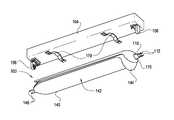
- FIG. 1Ais an assembled, perspective bottom view of an elongate LED luminaire used in connection with a troffer fixture according to an embodiment of the present invention.
- FIG. 1Bis a first exploded perspective view of the elongate LED luminaire illustrated in FIG. 1A .
- FIG. 1Cis a second exploded perspective view of the elongate LED luminaire illustrated in FIG. 1A .
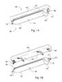
- FIG. 2Ais a side elevation view of a lamp of the elongate LED luminaire illustrated in FIG. 1A .
- FIG. 2Bis a front elevation view of the lamp illustrated in FIG. 2A .
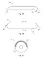
- FIG. 3Ais a side perspective view of a light guide of the elongate LED luminaire illustrated in FIG. 1A .
- FIG. 3Bis a top plan view of the light guide illustrated in FIG. 3A .
- FIG. 3Cis a cross-sectional view of the light guide illustrated in FIG. 3A and taken through line 3 - 3 in FIG. 3B .
- FIG. 4Ais a side elevation view of a heat dissipating frame of the elongate LED luminaire illustrated in FIG. 1A .
- FIG. 4Bis a top plan view of the heat dissipating frame illustrated in FIG. 4A .
- FIG. 4Cis a cross-sectional view of the heat dissipating frame illustrated in FIG. 4A and taken through line 4 - 4 in FIG. 4B .
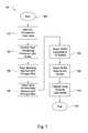
- FIG. 5is a flow chart detailing a method of retrofitting a fluorescent tube lamp with an elongate LED luminaire according to an embodiment of the present invention.
- the present inventionmay be referred to as the luminaire 100 , a lighting system, a digital light, an LED lighting system, a device, a system, a product, and a method.
- the present inventionmay be referred to as relating to replacement of linear fluorescent lamps, fluorescent tube lamps, tube lights, troffer tubes, and fluorescent light bulbs.
- this terminologyis only illustrative and does not affect the scope of the invention.
- the present inventionmay just as easily relate to lasers or other digital lighting technologies, and may operate as a retrofit for non-linear troffer tubes or to other fluorescent light configurations.
- Example devices, systems, and methods for an elongate LED luminaireare described herein below.
- numerous specific detailsare set forth to provide a thorough understanding of example embodiments. It will be evident, however, to one of ordinary skill in the art that the present invention may be practiced without these specific details and/or with different combinations of the details than are given here. Thus, specific embodiments are given for the purpose of simplified explanation and not limitation.
- the luminaire 100 shown as part of a lighting assembly 102 in FIG. 1A and also shown separately as a luminaire 100 in FIGS. 1B and 1Cmay be used alone or together with other similar lighting assemblies in a system of lighting assemblies.
- the luminaire 100may be configured as a retrofit to engage mechanically and operationally with a conventional fluorescent light fixture such as the light fixture 104 illustrated in FIGS. 1A-1C .
- the luminaire 100may be advantageously employed as a fluorescent tube replacement in a variety of applications including, but not limited to, direct-view or indirect-view interior or exterior space (e.g., architectural) lighting and illumination in general.
- the luminaire 100may also be advantageously used in connection with direct or indirect illumination of objects or spaces, theatrical or other entertainment-based/special effects lighting, decorative lighting, safety-oriented lighting, lighting associated with, or illumination of, displays and/or merchandise (e.g. for advertising and/or in retail/consumer environments), combined lighting or illumination and communication systems, as well as for various indication, display and information purposes.
- the luminaire 100may include a lamp 110 , a light guide 140 positioned in optical communication with the lamp 110 , and a heat dissipating frame 170 positioned in thermal communication with at least one of the lamp 110 and the light guide 140 . Additionally, the luminaire 100 may further include one or more mounting brackets 179 adapted to mechanically attach the luminaire 100 to a light fixture 104 . Although luminaire 100 is depicted as having an elongated basket shape in FIGS. 1A-1C , luminaire 100 and its constituent components may have any of a variety of other shapes, including planar and cylindrical.
- the lamp 110may include a bi-pin base 112 , a middle structure 120 connected to the bi-pin base 112 , and an outer structure 130 connected to the middle structure 120 .
- the outer structure 130may be attached to the middle structure 120 which, in turn, may be similarly connected to the bi-pin base 112 by any means known in the art, including, not by limitation, use of one or more of adhesives or glues, welding, and fasteners.
- FIGS. 2, 8, 9A, 9B, and 11and the written description thereof, of U.S. patent application Ser. No. 12/698,829 titled Luminaire With Prismatic Optic filed on May 3, 2012, the entire content of which is incorporated herein by reference.
- the bi-pin base 112may be configured to anchor to a fluorescent socket 106 . More specifically, the bi-pin base 112 may be configured to mechanically and electrically couple the lamp 110 to any standard fluorescent socket of a type that is well known in the art, including, but not limited to, medium bi-pin sockets (T8/T12), mini bi-pin sockets (T5/T5HO), single pin sockets (T12/T8), and U-bend medium bi-pin sockets. Additionally, the lamp 110 may be configured to conform to various sizes and configurations of the aforementioned sockets, including, but not limited to, turn-type sockets, pedestal sockets, and fixed-end sockets.
- the bi-pin base 112may include pin locks 114 designed to engage the fluorescent socket 106 from within the fluorescent socket pin contacts, rather than relying on pressure applied from outside the socket pin contacts to keep the lamp 110 from disengaging from the socket pin contacts due to minimal forces, such as gravity.
- the bi-pin base 112may be formed of an electrically conductive material, such as copper and/or aluminum.
- the middle structure 120 of the lamp 110may be configured to include a housing section 122 and a heat sink section 124 .
- the heat sink section 124may be formed of thermally conductive material and may be positioned in thermal communication with a light source 255 .
- Materials of the heat sink section 124may include, without limitation, thermoplastic, ceramics, porcelain, aluminum, aluminum alloys, metals, metal alloys, carbon allotropes, and composite materials.
- a portion of the heat sink section 124may include a plurality of fins 202 .
- the fins 202may be configured to run the length of the heat sink section 124 and may extend radially outward therefrom such that at least a distal edge of the fins 202 are substantially exposed to an environment external to the luminaire.
- the fins 202may increase the surface area of the heat sink section 124 and may permit fluid flow between adjacent pairs of fins 202 , thereby enhancing the cooling capability of the heat sink section 124 . Additional information directed to the use of heat sinks for dissipating heat in an illumination apparatus is found in U.S. Pat. No. 7,922,356 titled Illumination Apparatus for Conducting and Dissipating Heat from a Light Source, and in U.S. Pat. No. 7,824,075 titled Method and Apparatus for Cooling a Light Bulb, the entire contents of each of which are incorporated herein by reference.
- a proximal side of the substantially-cylindrical heat sink section 124may be positioned adjacent to a distal side of the substantially-cylindrical housing section 122 of the middle structure 120 .
- each of the heat sink section 124 and the housing section 122 of the middle structure 120 shown in FIG. 2Amay include a void such that the two voids cooperate with each other to define a longitudinal cavity (see also 208 in FIG. 2 of U.S. patent application Ser. No. 12/698,829 which is incorporated herein by reference).
- Electrical circuitrymay be configured to be substantially enclosed within the middle structure 120 according to an embodiment of the invention.
- a power source(not shown) may be configured to have a shape and sufficient dimensions to be disposed within the longitudinal cavity 208 of the middle structure 120 .
- the power supplymay be configured to convert and condition AC power to DC power for delivery to the light source 225 .
- the bi-pin base 112may conduct power from a light fixture that may provide 120-volt alternating current (AC) power.
- the light source 225may comprise LEDs 227 requiring direct current (DC) power at, for instance, five (5) volts.
- the power supplymay comprise circuitry for conditioning the 120-volt AC power to 5-volt DC power.
- the characteristics of the power being provided to the power supply and be provided by the power supplyare exemplary only, and a wide range of characteristics of electricity are contemplated included within the scope of the invention.
- the bi-pin base 112may conduct power from a light fixture that may provide power having a voltage within the range of from about 110 votes to about 250 V and a frequency within the range from about 40 Hz to about 70 Hz. Details regarding power supply systems that may be used in connection with the luminaire 100 according to an embodiment of the present invention may be found, for example, in U.S. Provisional Patent Application No. 61/486,322 titled Variable Load Power Supply, the entire content of which is incorporated herein by reference.
- the outer structure 130may include a shelf 210 , an optic 220 , and one or more light sources ( 225 ).
- the outer structure 130may be configured to permit the one or more light sources 225 to be disposed therein and positioned to direct light through the optic 220 .
- the shelf 210may be disposed about a perimeter of the outer structure 130 adjacent the interface between the outer structure 130 and the middle structure 120 .
- Each light source 225 carried by the outer structure 130may be provided as one of any number of embodiments.
- any one of the light sources 225may include light emitting elements 227 .
- the light emitting elements 227 that may be included in the outer structure 130may include one or more light-emitting diodes (LEDs) 227 .
- LEDslight-emitting diodes
- the lock lamp 110 illustrated in FIG. 2Bmay include any number of various types of light sources (e.g., all LED-based light sources, LED-based and non-LED-based light sources in combination, etc.) adapted to generate radiation of a variety of different colors, including essentially white light, as will be discussed further below. More specifically, embodiments of the present invention contemplate that any number of light sources may be provided, in addition to any number of different light sources.
- Each light source 225may be configured to emit a source light, which may be defined as a combination of the emissions of each light source 225 present in the lamp 110 .
- Each light source 225may be configured such that the emitted source light may be incident upon an inner surface 142 of the light guide 140 and subsequently projected generally radially outward from the lamp 110 .
- the light guide 140may be configured to alter the source light to create a shaped light having a uniform illuminance as projected into the environment exterior to the luminaire 100 .
- One or more of the components comprising the luminaire 100may be connected by any means or method known in the art, including, not by limitation, use of adhesives or glues, welding, interference fit, and fasteners.
- one or more components of the luminaire 100may be molded during manufacturing as an integral part of the luminaire 100 .
- the outer structure 130 of the lamp 110also may comprise a shelf 210 and an optic 220 .
- the light source 225may be disposed on the shelf 210 and oriented such that the source light emitted from the light source 225 passes through the optic 220 .
- the optic 220may be configured to direct the source light emitted from a light source 225 to be incident upon the light guide 140 .
- the optic 220may be formed of any transparent, translucent, or substantially translucent material including, but not limited to, glass, fluorite, and polymers, such as polycarbonate. Types of glass include, without limitation, fused quartz, soda-lime glass, lead glass, flint glass, fluoride glass, aluminosilicates, phosphate glass, borate glass, and chalcogenide glass.
- the light guide 140 of the present embodiment of the luminaire 100may include an inner surface 142 , an outer surface 144 , a mounting aperture 146 , and a bi-pin connector 148 .
- the components comprising the light guide 140may be connected by any means known in the art, including, not by limitation, use of adhesives or glues, welding, and fasteners.
- one or more components of the light guide 140may be molded during manufacturing as an integral part of the light guide 140 .
- a portion of the outer structure 130 of the lamp 110may be positioned adjacent to the light guide 140 in the assembled luminaire 100 .
- the light source 225 of the lamp 110may be configured to emit light incident upon the inner surface 142 of the light guide 140 .
- Materials present in the light guide 140may change the source light into a shaped light using at least one of collimation, concentration, refraction, conversion, reflection, and/or diffusion.
- the shaped lightmay illuminate a space proximate to the luminaire in a generally even distribution along the length and/or width of the light guide 140 .
- the light guide 140may have a bi-pin connector 148 configured to mechanically attach to a standard fluorescent socket 106 .
- the bi-pin connector 148may be configured to conform to a standard bi-pin socket 106 for a fluorescent lampholder that is well known in the art.
- the light guide 140may be configured to mechanically attach via the bi-pin connector 148 to any fluorescent socket 106 , including, but not limited to, medium bi-pin sockets (T8/T12), mini bi-pin sockets (T5/T5HO), single pin sockets (T12/T8), and U-bend medium bi-pin sockets.
- the bi-pin connector 148may be configured to conform to various sizes and configurations of the aforementioned sockets, including, but not limited to, turn-type sockets, pedestal sockets, and fixed-end sockets.
- the bi-pin connector 148may be made of a non-conductive material which may support mechanical attachment to the fluorescent socket 106 , but which may not allow electrical current to pass through the light guide 140 .
- the length of the bi-pin connector 148may be long enough to provide mechanical attachment to the fluorescent socket pin contacts, but not long enough to engage the electrical connections within the socket pin contacts.
- the light guide 140may have a substantially elongated-basket shape that defines an inner surface 142 and an outer surface 144 .
- the outer structure 130 of the lamp 110may be positioned adjacent to the inner surface 142 of the light guide 140 when the lamp 110 is received by the mounting aperture 146 of the light guide 140 .
- the one or more light sources 225 in the outer structure 130 of the lamp 110may be arranged such that each points substantially upwards towards a target reflective area on the inner surface 142 of the light guide 140 . This configuration may advantageously enhance light dispersion as light is emitted from the lamp 110 , resulting in an inexpensive way to distribute a light pattern that covers the entire target space proximate to the lighting system 100 .
- the mounting aperture 146may be positioned on a substantially frustoconical single end of the elongate-basket shaped light guide 140 that may be opposite a second end to which the bi-pin connector 148 may be connected.
- the mounting aperture 146may be sized to fittedly receive lamp 110 such that the bi-pin connector 112 and the middle structure 120 may pass through the mounting aperture 146 , but the shelf 210 of the outer structure 130 of the lamp 110 may be too large to pass through the mounting aperture 146 .
- the inner surface 142may include one or more of any type of reflective materials which may be known in the art.
- the inner surface 142may be formed of a material that is inherently reflective of light, and therefore a surface upon which emitted light may be incident inherently would be reflective.
- the inner surface 142may be formed of a material that may be polished to become reflective.
- the inner surface 142may be formed of a material that is permissive of a material being coated, attached, or otherwise disposed thereupon, the disposed material being reflective.
- the light guide 140may comprise layers of transmissive 310 and reflective 320 materials.
- the thickness and the orientation of the transmissive 310 and reflective 320 materialsmay be manipulated to alter the intensity and direction of the shaped light depending on the distance from a given reflective area on the inner surface 142 of the light guide 140 to the one or more light sources 225 in the outer structure 130 of a lamp 110 .
- a coatingmay be placed on the inner surface 142 of the light guide 140 to convert a wavelength of the source light so that the wavelength is defined has having a converted wavelength range.
- coatings used to convert a wavelength of a source lightsee U.S. patent application Ser. No. 13/234/371 titled Color Conversion Occlusion and Associated Methods, and U.S. patent application Ser. No.
- the luminairemay be configured to conform to a U-bend florescent bulb configuration, such that the luminaire may be a legacy retrofit for such a troffer fixture.
- the light guidemay be configured to redirect light such that light is emitted substantially equally throughout the light guide, including those sections of the light guide that are generally distal of the human relative to the light source.
- U-bend luminaire embodiments of the inventionmay be substantially similar or identical to the linear embodiment presented herein, including all necessary and optional features described therewith, with the exception of each feature that must be reconfigured to conform to a U-bend type troffer fixture.
- the heat dissipating frame 170 of the present embodiment of the lighting system 100may include a contact surface 172 , a mounting surface 174 , and a through-hole 176 .
- the contact surface 172 on the heat dissipating frame 170may be positioned in thermal communication with the outer surface 144 of the light guide 140 .
- the components comprising the heat dissipating frame 170may be connected by any means known in the art, including, not by limitation, use of adhesives or glues, welding, and fasteners.
- one or more components of the heat dissipating frame 170may be molded during manufacturing as an integral part of the heat dissipating frame 170 .
- a rim of the through-hole 176may be in thermal communication with the heat sink section 124 of the middle structure 120 of the lamp 110 .
- the heat dissipating frame 170 of the luminaire 100may include one or more heat sink rods 173 that may abut each other to define the contact surface 172 of the heat dissipating frame 170 .
- the heat dissipating frame 170may be made of aluminum or other heat-conducting material by molding, casting, or stamping.
- a through-hole 176may be disposed at a substantially frustoconical attaching end of the heat dissipating frame 170 .
- the through-hole 176may comprise a rim, defined as a perimeter of the through-hole 176 , that may be sized to mechanically and thermally couple the heat dissipating frame 170 to the heat sink section 124 of the middle structure 120 of the luminaire 100 (illustrated in FIG. 2A ).
- the through-hole 176 of the heat dissipating frame 170may be aligned with the mounting aperture 146 of the light guide 140 with the contact surface 172 of the heat dissipating frame 170 substantially adjacent to the outer surface 144 of the light guide 140 .
- the lamp 110may be received simultaneously by both the mounting aperture 146 and the through-hole 176 before mechanically and electrically engaging the fluorescent socket 106 with its bi-pin base 112 .
- the weight of the heat dissipating frame 170may be supported by the outer surface 144 of a light guide 140 that is mechanically attached to opposing fluorescent sockets 106 by the bi-pin connector 148 and by the anchored lamp 110 , respectively.
- the mounting surface 174 of the heat dissipating frame 170may be mechanically attached to a lighting assembly 102 using brackets 179 as illustrated in FIGS. 1B and 1C .
- the luminaire 100may be configured as a retrofit to engage mechanically and operationally with a conventional fluorescent light fixture.
- the luminaire 100 shown in FIGS. 1A, 1B, and 1Cis an advantageously simple and inexpensive retrofit option in terms of manufacturing, installation and maintenance.
- the design of the present inventionavoids the material waste inherent to prosthetic tube retrofit designs.
- the on-board power conditioning for LED-based lightingprovides for operation of the present invention using existing fluorescent light assembly circuitry and without requiring removal of fluorescent ballasts.
- the use of LEDs in connection with the lighting system 100 according to an embodiment of the present inventionalso advantageously provides decreased operating costs with respect to energy consumption.
- LED-based technologysupports tailoring of color temperature in ways not possible with standard fluorescent bulbs (e.g., color temperatures of 3000 Kelvin and below). Additionally, LED-based technology enables the adjustment of color temperature post-installation without requiring replacement of the bulb.
- a method aspect of the present inventionis directed to assembling a luminaire as a retrofit for a fluorescent tube lamp.
- the methodmay comprise the steps of removing the fluorescent tube lamp from a fluorescent light fixture, positioning the heat dissipating frame in thermal contact with the light guide, aligning the through-hole in the heat dissipating frame with a mounting aperture in the light guide, inserting the bi-pin base and the middle structure of the lamp through the mounting aperture in light guide and, in turn, through the through-hole of the heat dissipating frame such that outer structure of the lamp is fixedly attached to the light guide adjacent the mounting aperture.
- the methodalso may include attaching the bi-pin connector of the light guide to the first fluorescent socket, and mechanically and electrically attaching the pin lock of the bi-pin base to the second fluorescent socket.
- the methodalso may include positioning the light guide in relation to the light source such that the emitted source light is incident upon the light guide, and is changed by the light guide into the shaped light that illuminates the space proximate to the luminaire.
- the retrofit method 500may include the step of removing a legacy fluorescent lamp from the light fixture 106 (Block 510 ).
- the heat dissipating frame 170may be positioned to be carried by the light guide 140 .
- the contact surface 172 of the heat dissipating frame 170also may be positioned in thermal communication with the outer surface 144 of the light guide 140 .
- the through-hole 176 of the heat dissipating frame 170may be aligned with the mounting aperture 146 of the light guide 140 such that the lamp 110 may be received simultaneously by both the mounting aperture 146 and the through-hole 176 .
- the bi-pin base 112 and the middle structure 120 of the lamp 100may be inserted through the mounting aperture 146 and the through-hole 176 such that the shelf 210 of the outer structure 130 of the lamp 110 abuts the light guide 140 .
- the bi-pin connector 148 of the light guide 140may be mechanically attached to a first fluorescent socket 106 at Block 550 .
- the bi-pin base 112 of the lamp 110may be mechanically and electrically attached to a second fluorescent socket 106 at Block 560 .
- the weight of the heat dissipating frame 170may be supported by the outer surface 144 of the light guide 140 that is mechanically attached to opposing fluorescent sockets 106 by the bi-pin connector 148 and by the anchored lamp 110 , respectively.
- the light source 225 of the lamp 110may be configured to emit light incident upon the inner surface 142 of the light guide 140 such that the light guide 140 may change the source light into the shaped light that may illuminate the space proximate to the luminaire in a generally even distribution along the length and/or width of the light guide 140 .
- the processends at Block 575 .
Landscapes
- Engineering & Computer Science (AREA)
- General Engineering & Computer Science (AREA)
- Physics & Mathematics (AREA)
- Microelectronics & Electronic Packaging (AREA)
- Optics & Photonics (AREA)
- Non-Portable Lighting Devices Or Systems Thereof (AREA)
- Arrangement Of Elements, Cooling, Sealing, Or The Like Of Lighting Devices (AREA)
- Manufacturing & Machinery (AREA)
Abstract
Description
Claims (20)
Priority Applications (1)
| Application Number | Priority Date | Filing Date | Title |
|---|---|---|---|
| US14/844,353US9353916B2 (en) | 2012-10-03 | 2015-09-03 | Elongated LED luminaire and associated methods |
Applications Claiming Priority (3)
| Application Number | Priority Date | Filing Date | Title |
|---|---|---|---|
| US201261709325P | 2012-10-03 | 2012-10-03 | |
| US14/044,939US9127818B2 (en) | 2012-10-03 | 2013-10-03 | Elongated LED luminaire and associated methods |
| US14/844,353US9353916B2 (en) | 2012-10-03 | 2015-09-03 | Elongated LED luminaire and associated methods |
Related Parent Applications (1)
| Application Number | Title | Priority Date | Filing Date |
|---|---|---|---|
| US14/044,939ContinuationUS9127818B2 (en) | 2012-10-03 | 2013-10-03 | Elongated LED luminaire and associated methods |
Publications (2)
| Publication Number | Publication Date |
|---|---|
| US20150377424A1 US20150377424A1 (en) | 2015-12-31 |
| US9353916B2true US9353916B2 (en) | 2016-05-31 |
Family
ID=50974423
Family Applications (2)
| Application Number | Title | Priority Date | Filing Date |
|---|---|---|---|
| US14/044,939Expired - Fee RelatedUS9127818B2 (en) | 2012-10-03 | 2013-10-03 | Elongated LED luminaire and associated methods |
| US14/844,353Expired - Fee RelatedUS9353916B2 (en) | 2012-10-03 | 2015-09-03 | Elongated LED luminaire and associated methods |
Family Applications Before (1)
| Application Number | Title | Priority Date | Filing Date |
|---|---|---|---|
| US14/044,939Expired - Fee RelatedUS9127818B2 (en) | 2012-10-03 | 2013-10-03 | Elongated LED luminaire and associated methods |
Country Status (1)
| Country | Link |
|---|---|
| US (2) | US9127818B2 (en) |
Cited By (4)
| Publication number | Priority date | Publication date | Assignee | Title |
|---|---|---|---|---|
| US9788387B2 (en) | 2015-09-15 | 2017-10-10 | Biological Innovation & Optimization Systems, LLC | Systems and methods for controlling the spectral content of LED lighting devices |
| US9844116B2 (en) | 2015-09-15 | 2017-12-12 | Biological Innovation & Optimization Systems, LLC | Systems and methods for controlling the spectral content of LED lighting devices |
| US9943042B2 (en) | 2015-05-18 | 2018-04-17 | Biological Innovation & Optimization Systems, LLC | Grow light embodying power delivery and data communications features |
| US10595376B2 (en) | 2016-09-13 | 2020-03-17 | Biological Innovation & Optimization Systems, LLC | Systems and methods for controlling the spectral content of LED lighting devices |
Families Citing this family (7)
| Publication number | Priority date | Publication date | Assignee | Title |
|---|---|---|---|---|
| US9157581B2 (en) | 2009-10-05 | 2015-10-13 | Lighting Science Group Corporation | Low profile luminaire with light guide and associated systems and methods |
| US9581756B2 (en) | 2009-10-05 | 2017-02-28 | Lighting Science Group Corporation | Light guide for low profile luminaire |
| US9127818B2 (en)* | 2012-10-03 | 2015-09-08 | Lighting Science Group Corporation | Elongated LED luminaire and associated methods |
| US9269211B2 (en)* | 2013-04-23 | 2016-02-23 | Lighting Science Group Corporation | Autonomous luminaire assembly and vending system and associated methods |
| CN105829797B (en)* | 2013-12-20 | 2021-01-22 | 昕诺飞控股有限公司 | lighting equipment |
| US10499487B2 (en) | 2015-10-05 | 2019-12-03 | Scalia Lighting Technologies LLC | Light-emitting diode (LED) lighting fixture solutions and methods |
| US11262063B2 (en) | 2019-06-05 | 2022-03-01 | Light Source Engineering Llc | Horticulture light panel assembly |
Citations (205)
| Publication number | Priority date | Publication date | Assignee | Title |
|---|---|---|---|---|
| US4800473A (en) | 1987-07-06 | 1989-01-24 | Denis Tremblay | Venitian blind lamp |
| US4924357A (en) | 1985-12-17 | 1990-05-08 | Japan As Represented By Director General Of Agency Of Industrial Science And Technology | Light source unit for a business machine |
| US5057908A (en) | 1990-07-10 | 1991-10-15 | Iowa State University Research Foundation, Inc. | High power semiconductor device with integral heat sink |
| US5523878A (en) | 1994-06-30 | 1996-06-04 | Texas Instruments Incorporated | Self-assembled monolayer coating for micro-mechanical devices |
| US5704701A (en) | 1992-03-05 | 1998-01-06 | Rank Brimar Limited | Spatial light modulator system |
| EP0851260A2 (en) | 1996-12-16 | 1998-07-01 | Ngk Insulators, Ltd. | Display device |
| US5813753A (en) | 1997-05-27 | 1998-09-29 | Philips Electronics North America Corporation | UV/blue led-phosphor device with efficient conversion of UV/blues light to visible light |
| US5997150A (en) | 1995-10-25 | 1999-12-07 | Texas Instruments Incorporated | Multiple emitter illuminator engine |
| US6140646A (en) | 1998-12-17 | 2000-10-31 | Sarnoff Corporation | Direct view infrared MEMS structure |
| US6290382B1 (en) | 1998-08-17 | 2001-09-18 | Ppt Vision, Inc. | Fiber bundle combiner and led illumination system and method |
| US6341876B1 (en) | 1997-02-19 | 2002-01-29 | Digital Projection Limited | Illumination system |
| US6356700B1 (en) | 1998-06-08 | 2002-03-12 | Karlheinz Strobl | Efficient light engine systems, components and methods of manufacture |
| US6370168B1 (en) | 1999-10-20 | 2002-04-09 | Coherent, Inc. | Intracavity frequency-converted optically-pumped semiconductor laser |
| US20020151941A1 (en) | 2001-04-16 | 2002-10-17 | Shinichi Okawa | Medical illuminator, and medical apparatus having the medical illuminator |
| US6542671B1 (en) | 2001-12-12 | 2003-04-01 | Super Light Wave Corp. | Integrated 3-dimensional multi-layer thin-film optical couplers and attenuators |
| US6561656B1 (en) | 2001-09-17 | 2003-05-13 | Mitsubishi Denki Kabushiki Kaisha | Illumination optical system with reflecting light valve |
| US6594090B2 (en) | 2001-08-27 | 2003-07-15 | Eastman Kodak Company | Laser projection display system |
| US6647199B1 (en) | 1996-12-12 | 2003-11-11 | Teledyne Lighting And Display Products, Inc. | Lighting apparatus having low profile |
| US6707611B2 (en) | 1999-10-08 | 2004-03-16 | 3M Innovative Properties Company | Optical film with variable angle prisms |
| US20040052076A1 (en) | 1997-08-26 | 2004-03-18 | Mueller George G. | Controlled lighting methods and apparatus |
| US6733135B2 (en) | 2002-04-02 | 2004-05-11 | Samsung Electronics Co., Ltd. | Image projection apparatus |
| US6767111B1 (en) | 2003-02-26 | 2004-07-27 | Kuo-Yen Lai | Projection light source from light emitting diodes |
| US6817735B2 (en) | 2001-05-24 | 2004-11-16 | Matsushita Electric Industrial Co., Ltd. | Illumination light source |
| US6870523B1 (en) | 2000-06-07 | 2005-03-22 | Genoa Color Technologies | Device, system and method for electronic true color display |
| US6871982B2 (en) | 2003-01-24 | 2005-03-29 | Digital Optics International Corporation | High-density illumination system |
| US6893140B2 (en) | 2002-12-13 | 2005-05-17 | W. T. Storey, Inc. | Flashlight |
| US6921920B2 (en) | 2001-08-31 | 2005-07-26 | Smith & Nephew, Inc. | Solid-state light source |
| US6945672B2 (en) | 2002-08-30 | 2005-09-20 | Gelcore Llc | LED planar light source and low-profile headlight constructed therewith |
| US20050218780A1 (en) | 2002-09-09 | 2005-10-06 | Hsing Chen | Method for manufacturing a triple wavelengths white LED |
| US6964501B2 (en) | 2002-12-24 | 2005-11-15 | Altman Stage Lighting Co., Ltd. | Peltier-cooled LED lighting assembly |
| US6967761B2 (en) | 2000-10-31 | 2005-11-22 | Microsoft Corporation | Microelectrical mechanical structure (MEMS) optical modulator and optical display system |
| US6974713B2 (en) | 2000-08-11 | 2005-12-13 | Reflectivity, Inc. | Micromirrors with mechanisms for enhancing coupling of the micromirrors with electrostatic fields |
| US20060002110A1 (en) | 2004-03-15 | 2006-01-05 | Color Kinetics Incorporated | Methods and systems for providing lighting systems |
| US20060002108A1 (en) | 2004-06-30 | 2006-01-05 | Ouderkirk Andrew J | Phosphor based illumination system having a short pass reflector and method of making same |
| US7042623B1 (en) | 2004-10-19 | 2006-05-09 | Reflectivity, Inc | Light blocking layers in MEMS packages |
| US20060103777A1 (en) | 2004-11-15 | 2006-05-18 | 3M Innovative Properties Company | Optical film having a structured surface with rectangular based prisms |
| US7070281B2 (en) | 2002-12-04 | 2006-07-04 | Nec Viewtechnology, Ltd. | Light source device and projection display |
| US7072096B2 (en) | 2001-12-14 | 2006-07-04 | Digital Optics International, Corporation | Uniform illumination system |
| US7075707B1 (en) | 1998-11-25 | 2006-07-11 | Research Foundation Of The University Of Central Florida, Incorporated | Substrate design for optimized performance of up-conversion phosphors utilizing proper thermal management |
| US20060164005A1 (en) | 2005-01-25 | 2006-07-27 | Chuan-Sheng Sun | Illumination apparatus having adjustable color temperature and method for adjusting the color temperature |
| US7083304B2 (en) | 2003-08-01 | 2006-08-01 | Illumination Management Solutions, Inc. | Apparatus and method of using light sources of differing wavelengths in an unitized beam |
| US20060232992A1 (en) | 2003-08-12 | 2006-10-19 | Koninklijke Philips Electronics N.V. | Circuit arrangement for ac driving of organic diodes |
| US20060285193A1 (en) | 2005-06-03 | 2006-12-21 | Fuji Photo Film Co., Ltd. | Optical modulation element array |
| US20070013871A1 (en) | 2005-07-15 | 2007-01-18 | Marshall Stephen W | Light-emitting diode (LED) illumination in display systems using spatial light modulators (SLM) |
| US7178941B2 (en) | 2003-05-05 | 2007-02-20 | Color Kinetics Incorporated | Lighting methods and systems |
| US7178946B2 (en) | 2002-09-10 | 2007-02-20 | Honeywell International, Inc. | Luminaire device that restricts light within an angular envelope |
| US20070041167A1 (en) | 2005-08-19 | 2007-02-22 | Dai-Ichi Shomei Co., Ltd. | Medical lighting apparatus |
| US7184201B2 (en) | 2004-11-02 | 2007-02-27 | Texas Instruments Incorporated | Digital micro-mirror device having improved contrast and method for the same |
| US7187484B2 (en) | 2002-12-30 | 2007-03-06 | Texas Instruments Incorporated | Digital micromirror device with simplified drive electronics for use as temporal light modulator |
| US7213926B2 (en) | 2004-11-12 | 2007-05-08 | Hewlett-Packard Development Company, L.P. | Image projection system and method |
| US20070159492A1 (en) | 2006-01-11 | 2007-07-12 | Wintek Corporation | Image processing method and pixel arrangement used in the same |
| US7247874B2 (en) | 2003-05-26 | 2007-07-24 | Agfa-Gevaert Healthcare Gmbh | Device for detecting information contained in a phosphor layer |
| US7246923B2 (en) | 2004-02-11 | 2007-07-24 | 3M Innovative Properties Company | Reshaping light source modules and illumination systems using the same |
| US7255469B2 (en) | 2004-06-30 | 2007-08-14 | 3M Innovative Properties Company | Phosphor based illumination system having a light guide and an interference reflector |
| US20070188847A1 (en) | 2006-02-14 | 2007-08-16 | Texas Instruments Incorporated | MEMS device and method |
| US7261453B2 (en) | 2005-01-25 | 2007-08-28 | Morejon Israel J | LED polarizing optics for color illumination system and method of using same |
| US20070241340A1 (en) | 2006-04-17 | 2007-10-18 | Pan Shaoher X | Micro-mirror based display device having an improved light source |
| US7289090B2 (en) | 2003-12-10 | 2007-10-30 | Texas Instruments Incorporated | Pulsed LED scan-ring array for boosting display system lumens |
| US7300177B2 (en) | 2004-02-11 | 2007-11-27 | 3M Innovative Properties | Illumination system having a plurality of light source modules disposed in an array with a non-radially symmetrical aperture |
| US7303291B2 (en) | 2004-03-31 | 2007-12-04 | Sanyo Electric Co., Ltd. | Illumination apparatus and video projection display system |
| US7306352B2 (en) | 2004-10-19 | 2007-12-11 | Samsung Electronics Co., Ltd. | Illuminator |
| US7325956B2 (en) | 2005-01-25 | 2008-02-05 | Jabil Circuit, Inc. | Light-emitting diode (LED) illumination system for a digital micro-mirror device (DMD) and method of providing same |
| US7342658B2 (en) | 2005-12-28 | 2008-03-11 | Eastman Kodak Company | Programmable spectral imaging system |
| US7344280B2 (en) | 2002-09-30 | 2008-03-18 | Teledyne Lighting And Display Products, Inc. | Illuminator assembly |
| US7344279B2 (en) | 2003-12-11 | 2008-03-18 | Philips Solid-State Lighting Solutions, Inc. | Thermal management methods and apparatus for lighting devices |
| US7349095B2 (en) | 2005-05-19 | 2008-03-25 | Casio Computer Co., Ltd. | Light source apparatus and projection apparatus |
| US7353859B2 (en) | 2004-11-24 | 2008-04-08 | General Electric Company | Heat sink with microchannel cooling for power devices |
| US7382632B2 (en) | 2005-04-06 | 2008-06-03 | International Business Machines Corporation | Computer acoustic baffle and cable management system |
| US7382091B2 (en) | 2005-07-27 | 2008-06-03 | Lung-Chien Chen | White light emitting diode using phosphor excitation |
| US20080143973A1 (en) | 2006-10-12 | 2008-06-19 | Jing Miau Wu | Light source device of laser LED and projector having the same device |
| EP1950491A1 (en) | 2007-01-26 | 2008-07-30 | Piper Lux S.r.l. | LED spotlight |
| US20080198572A1 (en) | 2007-02-21 | 2008-08-21 | Medendorp Nicholas W | LED lighting systems including luminescent layers on remote reflectors |
| US7427146B2 (en) | 2004-02-11 | 2008-09-23 | 3M Innovative Properties Company | Light-collecting illumination system |
| US20080232116A1 (en) | 2007-03-22 | 2008-09-25 | Led Folio Corporation | Lighting device for a recessed light fixture |
| US20080232084A1 (en) | 2007-03-19 | 2008-09-25 | Nec Lighting, Ltd | White light source device |
| US7429983B2 (en) | 2005-11-01 | 2008-09-30 | Cheetah Omni, Llc | Packet-based digital display system |
| US7431489B2 (en) | 2004-11-17 | 2008-10-07 | Fusion Optix Inc. | Enhanced light fixture |
| US7434946B2 (en) | 2005-06-17 | 2008-10-14 | Texas Instruments Incorporated | Illumination system with integrated heat dissipation device for use in display systems employing spatial light modulators |
| US7438443B2 (en) | 2003-09-19 | 2008-10-21 | Ricoh Company, Limited | Lighting device, image-reading device, color-document reading apparatus, image-forming apparatus, projection apparatus |
| US20080258643A1 (en) | 2007-04-21 | 2008-10-23 | Zippy Technology Corp. | Method for driving alternate current of light emitting diode and operating voltage thereof |
| WO2008137732A1 (en) | 2007-05-04 | 2008-11-13 | Koninklijke Philips Electronics N V | Led-based fixtures and related methods for thermal management |
| US20080316432A1 (en) | 2007-06-25 | 2008-12-25 | Spotless, Llc | Digital Image Projection System |
| US20090009102A1 (en) | 2006-02-14 | 2009-01-08 | Koninklijke Philips Electronics N.V. | Lighting device with controllable light intensity |
| US7476016B2 (en) | 2005-06-28 | 2009-01-13 | Seiko Instruments Inc. | Illuminating device and display device including the same |
| US20090059099A1 (en) | 2007-09-05 | 2009-03-05 | Samsung Electronics Co., Ltd. | Illumination device and projection system having the same |
| US20090059585A1 (en) | 2007-08-29 | 2009-03-05 | Young Optics Inc. | Illumination system |
| US7530708B2 (en) | 2004-10-04 | 2009-05-12 | Lg Electronics Inc. | Surface emitting light source and projection display device using the same |
| US20090128781A1 (en) | 2006-06-13 | 2009-05-21 | Kenneth Li | LED multiplexer and recycler and micro-projector incorporating the Same |
| US7537347B2 (en) | 2005-11-29 | 2009-05-26 | Texas Instruments Incorporated | Method of combining dispersed light sources for projection display |
| US7540616B2 (en) | 2005-12-23 | 2009-06-02 | 3M Innovative Properties Company | Polarized, multicolor LED-based illumination source |
| US20090141506A1 (en) | 2007-12-03 | 2009-06-04 | Shih-Chi Lan | Illumination Device for Kitchen Hood |
| US7545569B2 (en) | 2006-01-13 | 2009-06-09 | Avery Dennison Corporation | Optical apparatus with flipped compound prism structures |
| US7556406B2 (en) | 2003-03-31 | 2009-07-07 | Lumination Llc | Led light with active cooling |
| US7591578B2 (en) | 2006-01-21 | 2009-09-22 | Hon Hai Precision Industry Co., Ltd. | Edge type backlight module having a reflective plate |
| US7598686B2 (en) | 1997-12-17 | 2009-10-06 | Philips Solid-State Lighting Solutions, Inc. | Organic light emitting diode methods and apparatus |
| US7605971B2 (en) | 2003-11-01 | 2009-10-20 | Silicon Quest Kabushiki-Kaisha | Plurality of hidden hinges for mircromirror device |
| US20090273931A1 (en) | 2007-01-15 | 2009-11-05 | Alps Electric Co., Ltd. | Illumination device and input unit with illumination device |
| US7626755B2 (en) | 2007-01-31 | 2009-12-01 | Panasonic Corporation | Wavelength converter and two-dimensional image display device |
| US20100006762A1 (en) | 2007-03-27 | 2010-01-14 | Kabushiki Kaisha Toshiba | Scintillator panel and radiation detector |
| US20100039704A1 (en) | 2006-10-27 | 2010-02-18 | Hideki Hayashi | Prism sheet and optical sheet |
| US7670021B2 (en) | 2007-09-27 | 2010-03-02 | Enertron, Inc. | Method and apparatus for thermally effective trim for light fixture |
| US20100051976A1 (en) | 2006-11-15 | 2010-03-04 | Lemnis Lighting Patent Holding B.V. | Led lighting assembly |
| US7677736B2 (en) | 2004-02-27 | 2010-03-16 | Panasonic Corporation | Illumination light source and two-dimensional image display using same |
| US7684007B2 (en) | 2004-08-23 | 2010-03-23 | The Boeing Company | Adaptive and interactive scene illumination |
| US7705810B2 (en) | 2003-05-07 | 2010-04-27 | Samsung Electronics Co., Ltd. | Four-color data processing system |
| US7703943B2 (en) | 2007-05-07 | 2010-04-27 | Intematix Corporation | Color tunable light source |
| US20100103389A1 (en) | 2008-10-28 | 2010-04-29 | Mcvea Kenneth Brian | Multi-MEMS Single Package MEMS Device |
| US7709811B2 (en) | 2007-07-03 | 2010-05-04 | Conner Arlie R | Light emitting diode illumination system |
| US7719766B2 (en) | 2007-06-20 | 2010-05-18 | Texas Instruments Incorporated | Illumination source and method therefor |
| US7728846B2 (en) | 2003-10-21 | 2010-06-01 | Samsung Electronics Co., Ltd. | Method and apparatus for converting from source color space to RGBW target color space |
| US7732825B2 (en) | 2007-03-13 | 2010-06-08 | Seoul Opto Device Co., Ltd. | AC light emitting diode |
| US7766490B2 (en) | 2006-12-13 | 2010-08-03 | Philips Lumileds Lighting Company, Llc | Multi-color primary light generation in a projection system using LEDs |
| US7771085B2 (en) | 2007-01-16 | 2010-08-10 | Steven Kim | Circular LED panel light |
| US20100202129A1 (en) | 2009-01-21 | 2010-08-12 | Abu-Ageel Nayef M | Illumination system utilizing wavelength conversion materials and light recycling |
| US7819556B2 (en) | 2006-12-22 | 2010-10-26 | Nuventix, Inc. | Thermal management system for LED array |
| US20100270942A1 (en) | 2009-04-24 | 2010-10-28 | City University Of Hong Kong | Apparatus and methods of operation of passive led lighting equipment |
| US7824075B2 (en) | 2006-06-08 | 2010-11-02 | Lighting Science Group Corporation | Method and apparatus for cooling a lightbulb |
| US7828453B2 (en) | 2009-03-10 | 2010-11-09 | Nepes Led Corporation | Light emitting device and lamp-cover structure containing luminescent material |
| US7835056B2 (en) | 2005-05-13 | 2010-11-16 | Her Majesty the Queen in Right of Canada, as represented by Institut National d'Optique | Image projector with flexible reflective analog modulator |
| US7834867B2 (en) | 2006-04-11 | 2010-11-16 | Microvision, Inc. | Integrated photonics module and devices using integrated photonics modules |
| US7832878B2 (en) | 2006-03-06 | 2010-11-16 | Innovations In Optics, Inc. | Light emitting diode projection system |
| US7841714B2 (en) | 2008-02-07 | 2010-11-30 | Quantum Modulation Scientific Inc. | Retinal melatonin suppressor |
| US20100321641A1 (en) | 2008-02-08 | 2010-12-23 | Koninklijke Philips Electronics N.V. | Light module device |
| US7871839B2 (en) | 2004-06-30 | 2011-01-18 | Seoul Opto Device Co., Ltd. | Light emitting element with a plurality of cells bonded, method of manufacturing the same, and light emitting device using the same |
| US7874690B2 (en) | 2008-06-24 | 2011-01-25 | Tyco Electronics Corporation | LED lighting fixture for illuminating a cavity |
| US7880400B2 (en) | 2007-09-21 | 2011-02-01 | Exclara, Inc. | Digital driver apparatus, method and system for solid state lighting |
| US7883241B2 (en) | 2008-05-06 | 2011-02-08 | Asustek Computer Inc. | Electronic device and heat dissipation unit thereof |
| US7889430B2 (en) | 2006-05-09 | 2011-02-15 | Ostendo Technologies, Inc. | LED-based high efficiency illumination systems for use in projection systems |
| US7906789B2 (en) | 2008-07-29 | 2011-03-15 | Seoul Semiconductor Co., Ltd. | Warm white light emitting apparatus and back light module comprising the same |
| US7906722B2 (en) | 2005-04-19 | 2011-03-15 | Palo Alto Research Center Incorporated | Concentrating solar collector with solid optical element |
| US20110080635A1 (en) | 2008-06-13 | 2011-04-07 | Katsuyuki Takeuchi | Image display device and image display method |
| US7922356B2 (en) | 2008-07-31 | 2011-04-12 | Lighting Science Group Corporation | Illumination apparatus for conducting and dissipating heat from a light source |
| US7928565B2 (en) | 2004-06-15 | 2011-04-19 | International Business Machines Corporation | Semiconductor device with a high thermal dissipation efficiency |
| US7972030B2 (en) | 2007-03-05 | 2011-07-05 | Intematix Corporation | Light emitting diode (LED) based lighting systems |
| US7976205B2 (en) | 2005-08-31 | 2011-07-12 | Osram Opto Semiconductors Gmbh | Light-emitting module, particularly for use in an optical projection apparatus |
| US8016443B2 (en) | 2008-05-02 | 2011-09-13 | Light Prescriptions Innovators, Llc | Remote-phosphor LED downlight |
| US8040070B2 (en) | 2008-01-23 | 2011-10-18 | Cree, Inc. | Frequency converted dimming signal generation |
| US8038314B2 (en) | 2009-01-21 | 2011-10-18 | Cooper Technologies Company | Light emitting diode troffer |
| US8047660B2 (en) | 2005-09-13 | 2011-11-01 | Texas Instruments Incorporated | Projection system and method including spatial light modulator and compact diffractive optics |
| US8049763B2 (en) | 2007-08-13 | 2011-11-01 | Samsung Electronics Co., Ltd. | RGB to RGBW color decomposition method and system |
| US8061857B2 (en) | 2008-11-21 | 2011-11-22 | Hong Kong Applied Science And Technology Research Institute Co. Ltd. | LED light shaping device and illumination system |
| US8070324B2 (en) | 2008-07-30 | 2011-12-06 | Mp Design Inc. | Thermal control system for a light-emitting diode fixture |
| US8070302B2 (en) | 2005-05-10 | 2011-12-06 | Iwasaki Electric Co., Ltd. | Laminate type light-emitting diode device, and reflection type light-emitting diode unit |
| US8076680B2 (en) | 2005-03-11 | 2011-12-13 | Seoul Semiconductor Co., Ltd. | LED package having an array of light emitting cells coupled in series |
| US8083364B2 (en) | 2008-12-29 | 2011-12-27 | Osram Sylvania Inc. | Remote phosphor LED illumination system |
| US8096668B2 (en) | 2008-01-16 | 2012-01-17 | Abu-Ageel Nayef M | Illumination systems utilizing wavelength conversion materials |
| EP2410240A1 (en) | 2009-03-17 | 2012-01-25 | Fediel System, S. L. | Optical device for an led light bulb |
| US20120051041A1 (en) | 2010-08-31 | 2012-03-01 | Cree, Inc. | Troffer-Style Fixture |
| US8188687B2 (en) | 2005-06-28 | 2012-05-29 | Seoul Opto Device Co., Ltd. | Light emitting device for AC power operation |
| US8201968B2 (en) | 2009-10-05 | 2012-06-19 | Lighting Science Group Corporation | Low profile light |
| US20120201034A1 (en) | 2009-09-25 | 2012-08-09 | Chia-Mao Li | Wide-Range Reflective Structure |
| US8251561B2 (en) | 2009-06-05 | 2012-08-28 | Sharp Kabushiki Kaisha | Light collimating lightguide |
| US20120218774A1 (en) | 2011-02-28 | 2012-08-30 | Livingston Troy W | Led light bulb |
| US8274089B2 (en) | 2006-09-30 | 2012-09-25 | Seoul Opto Device Co., Ltd. | Light emitting diode having light emitting cell with different size and light emitting device thereof |
| US8272763B1 (en) | 2009-10-02 | 2012-09-25 | Genesis LED Solutions | LED luminaire |
| WO2012135173A1 (en) | 2011-03-28 | 2012-10-04 | Lighting Science Group Corporation | Mems wavelength converting lighting device and associated methods |
| US20120262902A1 (en) | 2011-04-18 | 2012-10-18 | Cree, Inc. | Led luminaire including a thin phosphor layer applied to a remote reflector |
| US8297783B2 (en) | 2008-09-10 | 2012-10-30 | Samsung Electronics Co., Ltd. | Light emitting device and system providing white light with various color temperatures |
| US8297798B1 (en) | 2010-04-16 | 2012-10-30 | Cooper Technologies Company | LED lighting fixture |
| US8310171B2 (en) | 2009-03-13 | 2012-11-13 | Led Specialists Inc. | Line voltage dimmable constant current LED driver |
| US8319445B2 (en) | 2008-04-15 | 2012-11-27 | Boca Flasher, Inc. | Modified dimming LED driver |
| US8324840B2 (en) | 2009-06-04 | 2012-12-04 | Point Somee Limited Liability Company | Apparatus, method and system for providing AC line power to lighting devices |
| US8322889B2 (en) | 2006-09-12 | 2012-12-04 | GE Lighting Solutions, LLC | Piezofan and heat sink system for enhanced heat transfer |
| US8324823B2 (en) | 2008-09-05 | 2012-12-04 | Seoul Semiconductor Co., Ltd. | AC LED dimmer and dimming method thereby |
| US8331099B2 (en) | 2006-06-16 | 2012-12-11 | Robert Bosch Gmbh | Method for fixing an electrical or an electronic component, particularly a printed-circuit board, in a housing and fixing element therefor |
| US8328406B2 (en) | 2009-05-13 | 2012-12-11 | Oree, Inc. | Low-profile illumination device |
| US8337063B2 (en) | 2009-08-25 | 2012-12-25 | Stanley Electric Co., Ltd. | Vehicle light |
| US8337029B2 (en) | 2008-01-17 | 2012-12-25 | Intematix Corporation | Light emitting device with phosphor wavelength conversion |
| US20120327650A1 (en) | 2011-06-27 | 2012-12-27 | Cree, Inc. | Direct and back view led lighting system |
| US20130021792A1 (en) | 2011-07-24 | 2013-01-24 | Cree, Inc. | Modular indirect suspended/ceiling mount fixture |
| US8410725B2 (en) | 2007-06-05 | 2013-04-02 | Koninklijke Philips Electronics N.V. | Lighting system for horticultural applications |
| US8410717B2 (en) | 2009-06-04 | 2013-04-02 | Point Somee Limited Liability Company | Apparatus, method and system for providing AC line power to lighting devices |
| US8408725B1 (en) | 2011-09-16 | 2013-04-02 | Lighting Science Group Corporation | Remote light wavelength conversion device and associated methods |
| US8419254B2 (en) | 2010-12-31 | 2013-04-16 | Enlight Corporation | Flat tubularlamp |
| US8419249B2 (en) | 2009-04-15 | 2013-04-16 | Stanley Electric Co., Ltd. | Liquid-cooled LED lighting device |
| US8427590B2 (en) | 2009-05-29 | 2013-04-23 | Soraa, Inc. | Laser based display method and system |
| US8441210B2 (en) | 2006-01-20 | 2013-05-14 | Point Somee Limited Liability Company | Adaptive current regulation for solid state lighting |
| US8459856B2 (en) | 2007-12-19 | 2013-06-11 | Oree, Inc. | Planar white illumination apparatus |
| US8465167B2 (en) | 2011-09-16 | 2013-06-18 | Lighting Science Group Corporation | Color conversion occlusion and associated methods |
| US8531126B2 (en) | 2008-02-13 | 2013-09-10 | Canon Components, Inc. | White light emitting apparatus and line illuminator using the same in image reading apparatus |
| US8545034B2 (en) | 2012-01-24 | 2013-10-01 | Lighting Science Group Corporation | Dual characteristic color conversion enclosure and associated methods |
| US20130294071A1 (en) | 2012-05-03 | 2013-11-07 | Lighting Science Group Corporation | Luminaire with prismatic optic |
| US20130296976A1 (en) | 2012-05-07 | 2013-11-07 | Lighting Science Group Corporation | Dynamic wavelength adapting device to affect physiological response and associated methods |
| US20130294087A1 (en) | 2012-05-03 | 2013-11-07 | Lighting Science Group Corporation | Luminaire with prismatic optic |
| US8585242B2 (en) | 2010-02-04 | 2013-11-19 | Sternberg Lanterns, Inc. | Lighting system with light-emitting diodes and securing structure |
| US8598799B2 (en) | 2007-12-19 | 2013-12-03 | Epistar Corporation | Alternating current light emitting device |
| US8608348B2 (en) | 2011-05-13 | 2013-12-17 | Lighting Science Group Corporation | Sealed electrical device with cooling system and associated methods |
| US8613530B2 (en) | 2010-01-11 | 2013-12-24 | General Electric Company | Compact light-mixing LED light engine and white LED lamp with narrow beam and high CRI using same |
| US8616736B2 (en) | 2008-08-26 | 2013-12-31 | Dingguo Pan | Circular light-reflecting plate with triangular oriented prisms having identical cross section and circular plate lamp made therefrom |
| US20140056026A1 (en) | 2009-10-05 | 2014-02-27 | Lighting Science Group Corporation | Low profile luminaire with light guide and associated systems and methods |
| US8662672B2 (en) | 2007-10-08 | 2014-03-04 | Koninklijke Philips N.V. | Lighting device, array of lighting devices and optical projection device |
| US8672518B2 (en) | 2009-10-05 | 2014-03-18 | Lighting Science Group Corporation | Low profile light and accessory kit for the same |
| US8674613B2 (en) | 2009-06-22 | 2014-03-18 | Richard Landry Gray | Power reforming methods and associated multiphase lights |
| US8678787B2 (en) | 2006-12-09 | 2014-03-25 | Murata Manufacturing Co., Ltd. | Piezoelectric micro-blower |
| US8733949B2 (en) | 2007-12-24 | 2014-05-27 | Columbia Insurance Company | System for representing colors including an integrating light capsule |
| US8740410B2 (en) | 2010-02-25 | 2014-06-03 | Lunera Lighting, Inc. | Troffer-style light fixture with cross-lighting |
| US8770821B2 (en) | 2007-04-16 | 2014-07-08 | Koninklijke Philips N.V. | Optical arrangement with a light transmitting layer arranged to cover a portion of light entry surface of light guide and to transmit light diffusively |
| US8770773B2 (en) | 2007-12-07 | 2014-07-08 | Dexerials Corporation | Light source device and display device |
| US8794811B2 (en) | 2011-03-16 | 2014-08-05 | GE Lighting Solutions, LLC | Edge-illuminated flat panel and light module for same |
| US8803166B2 (en) | 2004-08-31 | 2014-08-12 | Epistar Corporation | Structure of AC light-emitting diode dies |
| US20140268870A1 (en) | 2013-03-12 | 2014-09-18 | Lighting Science Group Corporation | Edge lit lighting device |
| US8864340B2 (en) | 2009-10-05 | 2014-10-21 | Lighting Science Group Corporation | Low profile light having concave reflector and associated methods |
| US8998448B2 (en) | 2010-10-28 | 2015-04-07 | Hon Hai Precision Industry Co., Ltd. | LED tube lamp |
| US9028091B2 (en) | 2009-10-05 | 2015-05-12 | Lighting Science Group Corporation | Low profile light having elongated reflector and associated methods |
| US9127818B2 (en)* | 2012-10-03 | 2015-09-08 | Lighting Science Group Corporation | Elongated LED luminaire and associated methods |
- 2013
- 2013-10-03USUS14/044,939patent/US9127818B2/ennot_activeExpired - Fee Related
- 2015
- 2015-09-03USUS14/844,353patent/US9353916B2/ennot_activeExpired - Fee Related
Patent Citations (215)
| Publication number | Priority date | Publication date | Assignee | Title |
|---|---|---|---|---|
| US4924357A (en) | 1985-12-17 | 1990-05-08 | Japan As Represented By Director General Of Agency Of Industrial Science And Technology | Light source unit for a business machine |
| US4800473A (en) | 1987-07-06 | 1989-01-24 | Denis Tremblay | Venitian blind lamp |
| US5057908A (en) | 1990-07-10 | 1991-10-15 | Iowa State University Research Foundation, Inc. | High power semiconductor device with integral heat sink |
| US5704701A (en) | 1992-03-05 | 1998-01-06 | Rank Brimar Limited | Spatial light modulator system |
| US5523878A (en) | 1994-06-30 | 1996-06-04 | Texas Instruments Incorporated | Self-assembled monolayer coating for micro-mechanical devices |
| US5997150A (en) | 1995-10-25 | 1999-12-07 | Texas Instruments Incorporated | Multiple emitter illuminator engine |
| US6647199B1 (en) | 1996-12-12 | 2003-11-11 | Teledyne Lighting And Display Products, Inc. | Lighting apparatus having low profile |
| EP0851260A2 (en) | 1996-12-16 | 1998-07-01 | Ngk Insulators, Ltd. | Display device |
| US6341876B1 (en) | 1997-02-19 | 2002-01-29 | Digital Projection Limited | Illumination system |
| US5813753A (en) | 1997-05-27 | 1998-09-29 | Philips Electronics North America Corporation | UV/blue led-phosphor device with efficient conversion of UV/blues light to visible light |
| US20040052076A1 (en) | 1997-08-26 | 2004-03-18 | Mueller George G. | Controlled lighting methods and apparatus |
| US7845823B2 (en) | 1997-08-26 | 2010-12-07 | Philips Solid-State Lighting Solutions, Inc. | Controlled lighting methods and apparatus |
| US7598686B2 (en) | 1997-12-17 | 2009-10-06 | Philips Solid-State Lighting Solutions, Inc. | Organic light emitting diode methods and apparatus |
| US6356700B1 (en) | 1998-06-08 | 2002-03-12 | Karlheinz Strobl | Efficient light engine systems, components and methods of manufacture |
| US6290382B1 (en) | 1998-08-17 | 2001-09-18 | Ppt Vision, Inc. | Fiber bundle combiner and led illumination system and method |
| US7075707B1 (en) | 1998-11-25 | 2006-07-11 | Research Foundation Of The University Of Central Florida, Incorporated | Substrate design for optimized performance of up-conversion phosphors utilizing proper thermal management |
| US6140646A (en) | 1998-12-17 | 2000-10-31 | Sarnoff Corporation | Direct view infrared MEMS structure |
| US6707611B2 (en) | 1999-10-08 | 2004-03-16 | 3M Innovative Properties Company | Optical film with variable angle prisms |
| US6370168B1 (en) | 1999-10-20 | 2002-04-09 | Coherent, Inc. | Intracavity frequency-converted optically-pumped semiconductor laser |
| US6870523B1 (en) | 2000-06-07 | 2005-03-22 | Genoa Color Technologies | Device, system and method for electronic true color display |
| US6974713B2 (en) | 2000-08-11 | 2005-12-13 | Reflectivity, Inc. | Micromirrors with mechanisms for enhancing coupling of the micromirrors with electrostatic fields |
| US6967761B2 (en) | 2000-10-31 | 2005-11-22 | Microsoft Corporation | Microelectrical mechanical structure (MEMS) optical modulator and optical display system |
| US20050033119A1 (en) | 2001-04-16 | 2005-02-10 | J. Morita Manufacturing Corporation | Medical illuminator, and medical apparatus having the medical illuminator |
| US20020151941A1 (en) | 2001-04-16 | 2002-10-17 | Shinichi Okawa | Medical illuminator, and medical apparatus having the medical illuminator |
| US6817735B2 (en) | 2001-05-24 | 2004-11-16 | Matsushita Electric Industrial Co., Ltd. | Illumination light source |
| US6594090B2 (en) | 2001-08-27 | 2003-07-15 | Eastman Kodak Company | Laser projection display system |
| US6921920B2 (en) | 2001-08-31 | 2005-07-26 | Smith & Nephew, Inc. | Solid-state light source |
| US6561656B1 (en) | 2001-09-17 | 2003-05-13 | Mitsubishi Denki Kabushiki Kaisha | Illumination optical system with reflecting light valve |
| US6542671B1 (en) | 2001-12-12 | 2003-04-01 | Super Light Wave Corp. | Integrated 3-dimensional multi-layer thin-film optical couplers and attenuators |
| US7400439B2 (en) | 2001-12-14 | 2008-07-15 | Digital Optics International Corporation | Uniform illumination system |
| US7072096B2 (en) | 2001-12-14 | 2006-07-04 | Digital Optics International, Corporation | Uniform illumination system |
| US6733135B2 (en) | 2002-04-02 | 2004-05-11 | Samsung Electronics Co., Ltd. | Image projection apparatus |
| US6945672B2 (en) | 2002-08-30 | 2005-09-20 | Gelcore Llc | LED planar light source and low-profile headlight constructed therewith |
| US20050218780A1 (en) | 2002-09-09 | 2005-10-06 | Hsing Chen | Method for manufacturing a triple wavelengths white LED |
| US7178946B2 (en) | 2002-09-10 | 2007-02-20 | Honeywell International, Inc. | Luminaire device that restricts light within an angular envelope |
| US7344280B2 (en) | 2002-09-30 | 2008-03-18 | Teledyne Lighting And Display Products, Inc. | Illuminator assembly |
| US7070281B2 (en) | 2002-12-04 | 2006-07-04 | Nec Viewtechnology, Ltd. | Light source device and projection display |
| US6893140B2 (en) | 2002-12-13 | 2005-05-17 | W. T. Storey, Inc. | Flashlight |
| US6964501B2 (en) | 2002-12-24 | 2005-11-15 | Altman Stage Lighting Co., Ltd. | Peltier-cooled LED lighting assembly |
| US7187484B2 (en) | 2002-12-30 | 2007-03-06 | Texas Instruments Incorporated | Digital micromirror device with simplified drive electronics for use as temporal light modulator |
| US6871982B2 (en) | 2003-01-24 | 2005-03-29 | Digital Optics International Corporation | High-density illumination system |
| US7520642B2 (en) | 2003-01-24 | 2009-04-21 | Digital Optics International Corporation | High-density illumination system |
| US6767111B1 (en) | 2003-02-26 | 2004-07-27 | Kuo-Yen Lai | Projection light source from light emitting diodes |
| US7556406B2 (en) | 2003-03-31 | 2009-07-07 | Lumination Llc | Led light with active cooling |
| US7178941B2 (en) | 2003-05-05 | 2007-02-20 | Color Kinetics Incorporated | Lighting methods and systems |
| US7705810B2 (en) | 2003-05-07 | 2010-04-27 | Samsung Electronics Co., Ltd. | Four-color data processing system |
| US7247874B2 (en) | 2003-05-26 | 2007-07-24 | Agfa-Gevaert Healthcare Gmbh | Device for detecting information contained in a phosphor layer |
| US7083304B2 (en) | 2003-08-01 | 2006-08-01 | Illumination Management Solutions, Inc. | Apparatus and method of using light sources of differing wavelengths in an unitized beam |
| US20060232992A1 (en) | 2003-08-12 | 2006-10-19 | Koninklijke Philips Electronics N.V. | Circuit arrangement for ac driving of organic diodes |
| US7438443B2 (en) | 2003-09-19 | 2008-10-21 | Ricoh Company, Limited | Lighting device, image-reading device, color-document reading apparatus, image-forming apparatus, projection apparatus |
| US7728846B2 (en) | 2003-10-21 | 2010-06-01 | Samsung Electronics Co., Ltd. | Method and apparatus for converting from source color space to RGBW target color space |
| US7605971B2 (en) | 2003-11-01 | 2009-10-20 | Silicon Quest Kabushiki-Kaisha | Plurality of hidden hinges for mircromirror device |
| US7289090B2 (en) | 2003-12-10 | 2007-10-30 | Texas Instruments Incorporated | Pulsed LED scan-ring array for boosting display system lumens |
| US7344279B2 (en) | 2003-12-11 | 2008-03-18 | Philips Solid-State Lighting Solutions, Inc. | Thermal management methods and apparatus for lighting devices |
| US7427146B2 (en) | 2004-02-11 | 2008-09-23 | 3M Innovative Properties Company | Light-collecting illumination system |
| US7246923B2 (en) | 2004-02-11 | 2007-07-24 | 3M Innovative Properties Company | Reshaping light source modules and illumination systems using the same |
| US7300177B2 (en) | 2004-02-11 | 2007-11-27 | 3M Innovative Properties | Illumination system having a plurality of light source modules disposed in an array with a non-radially symmetrical aperture |
| US7677736B2 (en) | 2004-02-27 | 2010-03-16 | Panasonic Corporation | Illumination light source and two-dimensional image display using same |
| US20060002110A1 (en) | 2004-03-15 | 2006-01-05 | Color Kinetics Incorporated | Methods and systems for providing lighting systems |
| US7303291B2 (en) | 2004-03-31 | 2007-12-04 | Sanyo Electric Co., Ltd. | Illumination apparatus and video projection display system |
| US7928565B2 (en) | 2004-06-15 | 2011-04-19 | International Business Machines Corporation | Semiconductor device with a high thermal dissipation efficiency |
| US20060002108A1 (en) | 2004-06-30 | 2006-01-05 | Ouderkirk Andrew J | Phosphor based illumination system having a short pass reflector and method of making same |
| US7871839B2 (en) | 2004-06-30 | 2011-01-18 | Seoul Opto Device Co., Ltd. | Light emitting element with a plurality of cells bonded, method of manufacturing the same, and light emitting device using the same |
| US7255469B2 (en) | 2004-06-30 | 2007-08-14 | 3M Innovative Properties Company | Phosphor based illumination system having a light guide and an interference reflector |
| US7684007B2 (en) | 2004-08-23 | 2010-03-23 | The Boeing Company | Adaptive and interactive scene illumination |
| US8803166B2 (en) | 2004-08-31 | 2014-08-12 | Epistar Corporation | Structure of AC light-emitting diode dies |
| US7530708B2 (en) | 2004-10-04 | 2009-05-12 | Lg Electronics Inc. | Surface emitting light source and projection display device using the same |
| US7042623B1 (en) | 2004-10-19 | 2006-05-09 | Reflectivity, Inc | Light blocking layers in MEMS packages |
| US7306352B2 (en) | 2004-10-19 | 2007-12-11 | Samsung Electronics Co., Ltd. | Illuminator |
| US7184201B2 (en) | 2004-11-02 | 2007-02-27 | Texas Instruments Incorporated | Digital micro-mirror device having improved contrast and method for the same |
| US7213926B2 (en) | 2004-11-12 | 2007-05-08 | Hewlett-Packard Development Company, L.P. | Image projection system and method |
| US20060103777A1 (en) | 2004-11-15 | 2006-05-18 | 3M Innovative Properties Company | Optical film having a structured surface with rectangular based prisms |
| US7431489B2 (en) | 2004-11-17 | 2008-10-07 | Fusion Optix Inc. | Enhanced light fixture |
| US7353859B2 (en) | 2004-11-24 | 2008-04-08 | General Electric Company | Heat sink with microchannel cooling for power devices |
| US20060164005A1 (en) | 2005-01-25 | 2006-07-27 | Chuan-Sheng Sun | Illumination apparatus having adjustable color temperature and method for adjusting the color temperature |
| US7325956B2 (en) | 2005-01-25 | 2008-02-05 | Jabil Circuit, Inc. | Light-emitting diode (LED) illumination system for a digital micro-mirror device (DMD) and method of providing same |
| US7261453B2 (en) | 2005-01-25 | 2007-08-28 | Morejon Israel J | LED polarizing optics for color illumination system and method of using same |
| US8076680B2 (en) | 2005-03-11 | 2011-12-13 | Seoul Semiconductor Co., Ltd. | LED package having an array of light emitting cells coupled in series |
| US7382632B2 (en) | 2005-04-06 | 2008-06-03 | International Business Machines Corporation | Computer acoustic baffle and cable management system |
| US7906722B2 (en) | 2005-04-19 | 2011-03-15 | Palo Alto Research Center Incorporated | Concentrating solar collector with solid optical element |
| US8070302B2 (en) | 2005-05-10 | 2011-12-06 | Iwasaki Electric Co., Ltd. | Laminate type light-emitting diode device, and reflection type light-emitting diode unit |
| US7835056B2 (en) | 2005-05-13 | 2010-11-16 | Her Majesty the Queen in Right of Canada, as represented by Institut National d'Optique | Image projector with flexible reflective analog modulator |
| US7349095B2 (en) | 2005-05-19 | 2008-03-25 | Casio Computer Co., Ltd. | Light source apparatus and projection apparatus |
| US20060285193A1 (en) | 2005-06-03 | 2006-12-21 | Fuji Photo Film Co., Ltd. | Optical modulation element array |
| US7434946B2 (en) | 2005-06-17 | 2008-10-14 | Texas Instruments Incorporated | Illumination system with integrated heat dissipation device for use in display systems employing spatial light modulators |
| US8188687B2 (en) | 2005-06-28 | 2012-05-29 | Seoul Opto Device Co., Ltd. | Light emitting device for AC power operation |
| US9030110B2 (en) | 2005-06-28 | 2015-05-12 | Seoul Viosys Co., Ltd. | Light emitting device for AC power operation |
| US7476016B2 (en) | 2005-06-28 | 2009-01-13 | Seiko Instruments Inc. | Illuminating device and display device including the same |
| US20070013871A1 (en) | 2005-07-15 | 2007-01-18 | Marshall Stephen W | Light-emitting diode (LED) illumination in display systems using spatial light modulators (SLM) |
| US7382091B2 (en) | 2005-07-27 | 2008-06-03 | Lung-Chien Chen | White light emitting diode using phosphor excitation |
| US20070041167A1 (en) | 2005-08-19 | 2007-02-22 | Dai-Ichi Shomei Co., Ltd. | Medical lighting apparatus |
| US7976205B2 (en) | 2005-08-31 | 2011-07-12 | Osram Opto Semiconductors Gmbh | Light-emitting module, particularly for use in an optical projection apparatus |
| US8047660B2 (en) | 2005-09-13 | 2011-11-01 | Texas Instruments Incorporated | Projection system and method including spatial light modulator and compact diffractive optics |
| US7429983B2 (en) | 2005-11-01 | 2008-09-30 | Cheetah Omni, Llc | Packet-based digital display system |
| US7537347B2 (en) | 2005-11-29 | 2009-05-26 | Texas Instruments Incorporated | Method of combining dispersed light sources for projection display |
| US7540616B2 (en) | 2005-12-23 | 2009-06-02 | 3M Innovative Properties Company | Polarized, multicolor LED-based illumination source |
| US7342658B2 (en) | 2005-12-28 | 2008-03-11 | Eastman Kodak Company | Programmable spectral imaging system |
| US20070159492A1 (en) | 2006-01-11 | 2007-07-12 | Wintek Corporation | Image processing method and pixel arrangement used in the same |
| US7545569B2 (en) | 2006-01-13 | 2009-06-09 | Avery Dennison Corporation | Optical apparatus with flipped compound prism structures |
| US8441210B2 (en) | 2006-01-20 | 2013-05-14 | Point Somee Limited Liability Company | Adaptive current regulation for solid state lighting |
| US7591578B2 (en) | 2006-01-21 | 2009-09-22 | Hon Hai Precision Industry Co., Ltd. | Edge type backlight module having a reflective plate |
| US20070188847A1 (en) | 2006-02-14 | 2007-08-16 | Texas Instruments Incorporated | MEMS device and method |
| US20090009102A1 (en) | 2006-02-14 | 2009-01-08 | Koninklijke Philips Electronics N.V. | Lighting device with controllable light intensity |
| US7832878B2 (en) | 2006-03-06 | 2010-11-16 | Innovations In Optics, Inc. | Light emitting diode projection system |
| US7834867B2 (en) | 2006-04-11 | 2010-11-16 | Microvision, Inc. | Integrated photonics module and devices using integrated photonics modules |
| US20070241340A1 (en) | 2006-04-17 | 2007-10-18 | Pan Shaoher X | Micro-mirror based display device having an improved light source |
| US7889430B2 (en) | 2006-05-09 | 2011-02-15 | Ostendo Technologies, Inc. | LED-based high efficiency illumination systems for use in projection systems |
| US7824075B2 (en) | 2006-06-08 | 2010-11-02 | Lighting Science Group Corporation | Method and apparatus for cooling a lightbulb |
| US20090128781A1 (en) | 2006-06-13 | 2009-05-21 | Kenneth Li | LED multiplexer and recycler and micro-projector incorporating the Same |
| US8331099B2 (en) | 2006-06-16 | 2012-12-11 | Robert Bosch Gmbh | Method for fixing an electrical or an electronic component, particularly a printed-circuit board, in a housing and fixing element therefor |
| US8322889B2 (en) | 2006-09-12 | 2012-12-04 | GE Lighting Solutions, LLC | Piezofan and heat sink system for enhanced heat transfer |
| US8274089B2 (en) | 2006-09-30 | 2012-09-25 | Seoul Opto Device Co., Ltd. | Light emitting diode having light emitting cell with different size and light emitting device thereof |
| US20080143973A1 (en) | 2006-10-12 | 2008-06-19 | Jing Miau Wu | Light source device of laser LED and projector having the same device |
| US20100039704A1 (en) | 2006-10-27 | 2010-02-18 | Hideki Hayashi | Prism sheet and optical sheet |
| US20100051976A1 (en) | 2006-11-15 | 2010-03-04 | Lemnis Lighting Patent Holding B.V. | Led lighting assembly |
| US8678787B2 (en) | 2006-12-09 | 2014-03-25 | Murata Manufacturing Co., Ltd. | Piezoelectric micro-blower |
| US7766490B2 (en) | 2006-12-13 | 2010-08-03 | Philips Lumileds Lighting Company, Llc | Multi-color primary light generation in a projection system using LEDs |
| US7819556B2 (en) | 2006-12-22 | 2010-10-26 | Nuventix, Inc. | Thermal management system for LED array |
| US20090273931A1 (en) | 2007-01-15 | 2009-11-05 | Alps Electric Co., Ltd. | Illumination device and input unit with illumination device |
| US7771085B2 (en) | 2007-01-16 | 2010-08-10 | Steven Kim | Circular LED panel light |
| EP1950491A1 (en) | 2007-01-26 | 2008-07-30 | Piper Lux S.r.l. | LED spotlight |
| US7626755B2 (en) | 2007-01-31 | 2009-12-01 | Panasonic Corporation | Wavelength converter and two-dimensional image display device |
| US20080198572A1 (en) | 2007-02-21 | 2008-08-21 | Medendorp Nicholas W | LED lighting systems including luminescent layers on remote reflectors |
| US7972030B2 (en) | 2007-03-05 | 2011-07-05 | Intematix Corporation | Light emitting diode (LED) based lighting systems |
| US7732825B2 (en) | 2007-03-13 | 2010-06-08 | Seoul Opto Device Co., Ltd. | AC light emitting diode |
| US20080232084A1 (en) | 2007-03-19 | 2008-09-25 | Nec Lighting, Ltd | White light source device |
| US20080232116A1 (en) | 2007-03-22 | 2008-09-25 | Led Folio Corporation | Lighting device for a recessed light fixture |
| US20100006762A1 (en) | 2007-03-27 | 2010-01-14 | Kabushiki Kaisha Toshiba | Scintillator panel and radiation detector |
| US8770821B2 (en) | 2007-04-16 | 2014-07-08 | Koninklijke Philips N.V. | Optical arrangement with a light transmitting layer arranged to cover a portion of light entry surface of light guide and to transmit light diffusively |
| US20080258643A1 (en) | 2007-04-21 | 2008-10-23 | Zippy Technology Corp. | Method for driving alternate current of light emitting diode and operating voltage thereof |
| WO2008137732A1 (en) | 2007-05-04 | 2008-11-13 | Koninklijke Philips Electronics N V | Led-based fixtures and related methods for thermal management |
| US7828465B2 (en) | 2007-05-04 | 2010-11-09 | Koninlijke Philips Electronis N.V. | LED-based fixtures and related methods for thermal management |
| US7703943B2 (en) | 2007-05-07 | 2010-04-27 | Intematix Corporation | Color tunable light source |
| US8410725B2 (en) | 2007-06-05 | 2013-04-02 | Koninklijke Philips Electronics N.V. | Lighting system for horticultural applications |
| US7719766B2 (en) | 2007-06-20 | 2010-05-18 | Texas Instruments Incorporated | Illumination source and method therefor |
| US20080316432A1 (en) | 2007-06-25 | 2008-12-25 | Spotless, Llc | Digital Image Projection System |
| US7709811B2 (en) | 2007-07-03 | 2010-05-04 | Conner Arlie R | Light emitting diode illumination system |
| US8049763B2 (en) | 2007-08-13 | 2011-11-01 | Samsung Electronics Co., Ltd. | RGB to RGBW color decomposition method and system |
| US20090059585A1 (en) | 2007-08-29 | 2009-03-05 | Young Optics Inc. | Illumination system |
| US20090059099A1 (en) | 2007-09-05 | 2009-03-05 | Samsung Electronics Co., Ltd. | Illumination device and projection system having the same |
| US7880400B2 (en) | 2007-09-21 | 2011-02-01 | Exclara, Inc. | Digital driver apparatus, method and system for solid state lighting |
| US7670021B2 (en) | 2007-09-27 | 2010-03-02 | Enertron, Inc. | Method and apparatus for thermally effective trim for light fixture |
| US8662672B2 (en) | 2007-10-08 | 2014-03-04 | Koninklijke Philips N.V. | Lighting device, array of lighting devices and optical projection device |
| US20090141506A1 (en) | 2007-12-03 | 2009-06-04 | Shih-Chi Lan | Illumination Device for Kitchen Hood |
| US8770773B2 (en) | 2007-12-07 | 2014-07-08 | Dexerials Corporation | Light source device and display device |
| US8598799B2 (en) | 2007-12-19 | 2013-12-03 | Epistar Corporation | Alternating current light emitting device |
| US8459856B2 (en) | 2007-12-19 | 2013-06-11 | Oree, Inc. | Planar white illumination apparatus |
| US8733949B2 (en) | 2007-12-24 | 2014-05-27 | Columbia Insurance Company | System for representing colors including an integrating light capsule |
| US8096668B2 (en) | 2008-01-16 | 2012-01-17 | Abu-Ageel Nayef M | Illumination systems utilizing wavelength conversion materials |
| US8337029B2 (en) | 2008-01-17 | 2012-12-25 | Intematix Corporation | Light emitting device with phosphor wavelength conversion |
| US8115419B2 (en) | 2008-01-23 | 2012-02-14 | Cree, Inc. | Lighting control device for controlling dimming, lighting device including a control device, and method of controlling lighting |
| US8040070B2 (en) | 2008-01-23 | 2011-10-18 | Cree, Inc. | Frequency converted dimming signal generation |
| US7841714B2 (en) | 2008-02-07 | 2010-11-30 | Quantum Modulation Scientific Inc. | Retinal melatonin suppressor |
| US20100321641A1 (en) | 2008-02-08 | 2010-12-23 | Koninklijke Philips Electronics N.V. | Light module device |
| US8531126B2 (en) | 2008-02-13 | 2013-09-10 | Canon Components, Inc. | White light emitting apparatus and line illuminator using the same in image reading apparatus |
| US8319445B2 (en) | 2008-04-15 | 2012-11-27 | Boca Flasher, Inc. | Modified dimming LED driver |
| US8016443B2 (en) | 2008-05-02 | 2011-09-13 | Light Prescriptions Innovators, Llc | Remote-phosphor LED downlight |
| US7883241B2 (en) | 2008-05-06 | 2011-02-08 | Asustek Computer Inc. | Electronic device and heat dissipation unit thereof |
| US20110080635A1 (en) | 2008-06-13 | 2011-04-07 | Katsuyuki Takeuchi | Image display device and image display method |
| US7874690B2 (en) | 2008-06-24 | 2011-01-25 | Tyco Electronics Corporation | LED lighting fixture for illuminating a cavity |
| US7906789B2 (en) | 2008-07-29 | 2011-03-15 | Seoul Semiconductor Co., Ltd. | Warm white light emitting apparatus and back light module comprising the same |
| US8070324B2 (en) | 2008-07-30 | 2011-12-06 | Mp Design Inc. | Thermal control system for a light-emitting diode fixture |
| US7922356B2 (en) | 2008-07-31 | 2011-04-12 | Lighting Science Group Corporation | Illumination apparatus for conducting and dissipating heat from a light source |
| US8616736B2 (en) | 2008-08-26 | 2013-12-31 | Dingguo Pan | Circular light-reflecting plate with triangular oriented prisms having identical cross section and circular plate lamp made therefrom |
| US8324823B2 (en) | 2008-09-05 | 2012-12-04 | Seoul Semiconductor Co., Ltd. | AC LED dimmer and dimming method thereby |
| US8297783B2 (en) | 2008-09-10 | 2012-10-30 | Samsung Electronics Co., Ltd. | Light emitting device and system providing white light with various color temperatures |
| US20100103389A1 (en) | 2008-10-28 | 2010-04-29 | Mcvea Kenneth Brian | Multi-MEMS Single Package MEMS Device |
| US8061857B2 (en) | 2008-11-21 | 2011-11-22 | Hong Kong Applied Science And Technology Research Institute Co. Ltd. | LED light shaping device and illumination system |
| US8083364B2 (en) | 2008-12-29 | 2011-12-27 | Osram Sylvania Inc. | Remote phosphor LED illumination system |
| US20120002411A1 (en) | 2009-01-21 | 2012-01-05 | Cooper Technologies Company | Light Emitting Diode Troffer |
| US20100202129A1 (en) | 2009-01-21 | 2010-08-12 | Abu-Ageel Nayef M | Illumination system utilizing wavelength conversion materials and light recycling |
| US8038314B2 (en) | 2009-01-21 | 2011-10-18 | Cooper Technologies Company | Light emitting diode troffer |
| US7828453B2 (en) | 2009-03-10 | 2010-11-09 | Nepes Led Corporation | Light emitting device and lamp-cover structure containing luminescent material |
| US8310171B2 (en) | 2009-03-13 | 2012-11-13 | Led Specialists Inc. | Line voltage dimmable constant current LED driver |
| EP2410240A1 (en) | 2009-03-17 | 2012-01-25 | Fediel System, S. L. | Optical device for an led light bulb |
| US8419249B2 (en) | 2009-04-15 | 2013-04-16 | Stanley Electric Co., Ltd. | Liquid-cooled LED lighting device |
| US20100270942A1 (en) | 2009-04-24 | 2010-10-28 | City University Of Hong Kong | Apparatus and methods of operation of passive led lighting equipment |
| US8328406B2 (en) | 2009-05-13 | 2012-12-11 | Oree, Inc. | Low-profile illumination device |
| US8427590B2 (en) | 2009-05-29 | 2013-04-23 | Soraa, Inc. | Laser based display method and system |
| US8410717B2 (en) | 2009-06-04 | 2013-04-02 | Point Somee Limited Liability Company | Apparatus, method and system for providing AC line power to lighting devices |
| US8324840B2 (en) | 2009-06-04 | 2012-12-04 | Point Somee Limited Liability Company | Apparatus, method and system for providing AC line power to lighting devices |
| US8251561B2 (en) | 2009-06-05 | 2012-08-28 | Sharp Kabushiki Kaisha | Light collimating lightguide |
| US8674613B2 (en) | 2009-06-22 | 2014-03-18 | Richard Landry Gray | Power reforming methods and associated multiphase lights |
| US8337063B2 (en) | 2009-08-25 | 2012-12-25 | Stanley Electric Co., Ltd. | Vehicle light |
| US20120201034A1 (en) | 2009-09-25 | 2012-08-09 | Chia-Mao Li | Wide-Range Reflective Structure |
| US8272763B1 (en) | 2009-10-02 | 2012-09-25 | Genesis LED Solutions | LED luminaire |
| US8864340B2 (en) | 2009-10-05 | 2014-10-21 | Lighting Science Group Corporation | Low profile light having concave reflector and associated methods |
| US8672518B2 (en) | 2009-10-05 | 2014-03-18 | Lighting Science Group Corporation | Low profile light and accessory kit for the same |
| US8201968B2 (en) | 2009-10-05 | 2012-06-19 | Lighting Science Group Corporation | Low profile light |
| US9028091B2 (en) | 2009-10-05 | 2015-05-12 | Lighting Science Group Corporation | Low profile light having elongated reflector and associated methods |
| US20140056026A1 (en) | 2009-10-05 | 2014-02-27 | Lighting Science Group Corporation | Low profile luminaire with light guide and associated systems and methods |
| US8613530B2 (en) | 2010-01-11 | 2013-12-24 | General Electric Company | Compact light-mixing LED light engine and white LED lamp with narrow beam and high CRI using same |
| US8585242B2 (en) | 2010-02-04 | 2013-11-19 | Sternberg Lanterns, Inc. | Lighting system with light-emitting diodes and securing structure |
| US8740410B2 (en) | 2010-02-25 | 2014-06-03 | Lunera Lighting, Inc. | Troffer-style light fixture with cross-lighting |
| US8297798B1 (en) | 2010-04-16 | 2012-10-30 | Cooper Technologies Company | LED lighting fixture |
| US20120051041A1 (en) | 2010-08-31 | 2012-03-01 | Cree, Inc. | Troffer-Style Fixture |
| US8998448B2 (en) | 2010-10-28 | 2015-04-07 | Hon Hai Precision Industry Co., Ltd. | LED tube lamp |
| US8419254B2 (en) | 2010-12-31 | 2013-04-16 | Enlight Corporation | Flat tubularlamp |
| US20120218774A1 (en) | 2011-02-28 | 2012-08-30 | Livingston Troy W | Led light bulb |
| US8794811B2 (en) | 2011-03-16 | 2014-08-05 | GE Lighting Solutions, LLC | Edge-illuminated flat panel and light module for same |
| US8730558B2 (en) | 2011-03-28 | 2014-05-20 | Lighting Science Group Corporation | Wavelength converting lighting device and associated methods |
| US8384984B2 (en) | 2011-03-28 | 2013-02-26 | Lighting Science Group Corporation | MEMS wavelength converting lighting device and associated methods |
| WO2012135173A1 (en) | 2011-03-28 | 2012-10-04 | Lighting Science Group Corporation | Mems wavelength converting lighting device and associated methods |
| US20120262902A1 (en) | 2011-04-18 | 2012-10-18 | Cree, Inc. | Led luminaire including a thin phosphor layer applied to a remote reflector |
| US8608348B2 (en) | 2011-05-13 | 2013-12-17 | Lighting Science Group Corporation | Sealed electrical device with cooling system and associated methods |
| US20120327650A1 (en) | 2011-06-27 | 2012-12-27 | Cree, Inc. | Direct and back view led lighting system |
| US20130021792A1 (en) | 2011-07-24 | 2013-01-24 | Cree, Inc. | Modular indirect suspended/ceiling mount fixture |
| US8408725B1 (en) | 2011-09-16 | 2013-04-02 | Lighting Science Group Corporation | Remote light wavelength conversion device and associated methods |
| US8465167B2 (en) | 2011-09-16 | 2013-06-18 | Lighting Science Group Corporation | Color conversion occlusion and associated methods |
| US8545034B2 (en) | 2012-01-24 | 2013-10-01 | Lighting Science Group Corporation | Dual characteristic color conversion enclosure and associated methods |
| US20130294087A1 (en) | 2012-05-03 | 2013-11-07 | Lighting Science Group Corporation | Luminaire with prismatic optic |
| US20130294071A1 (en) | 2012-05-03 | 2013-11-07 | Lighting Science Group Corporation | Luminaire with prismatic optic |
| US20130296976A1 (en) | 2012-05-07 | 2013-11-07 | Lighting Science Group Corporation | Dynamic wavelength adapting device to affect physiological response and associated methods |
| US9127818B2 (en)* | 2012-10-03 | 2015-09-08 | Lighting Science Group Corporation | Elongated LED luminaire and associated methods |
| US20140268870A1 (en) | 2013-03-12 | 2014-09-18 | Lighting Science Group Corporation | Edge lit lighting device |
Non-Patent Citations (12)
| Title |
|---|
| Arthur P. Fraas, Heat Exchanger Design, 1989, p. 60, John Wiley & Sons, Inc., Canada. |
| EP International Search Report for Application No. 10174449.8; (Dec. 14, 2010). |
| EP International Written Opinion for Application No. 10174449.8; (Dec. 14, 2010). |
| H. A El-Shaikh, S. V. Garimella, "Enhancement of Air Jet Impingement Heat Transfer using Pin-Fin Heat Sinks", D IEEE Transactions on Components and Packaging Technology, Jun. 2000, vol. 23, No. 2. |
| J. Y. San, C. H. Huang, M. H, Shu, "Impingement cooling of a confined circular air jet", In t. J. Heat Mass Transf., 1997. pp. 1355-1364, vol. 40. |
| Jones, Eric D., Light Emitting Diodes (LEDS) for General Lumination, an Optoelectronics Industry Development Association (OIDA) Technology Roadmap, OIDA Report, Mar. 2001, published by OIDA in Washington D.C. |
| N. T. Obot, W. J. Douglas, A S. Mujumdar, "Effect of Semi-confinement on Impingement Heat Transfer", Proc. 7th Int. Heat Transf. Conf., 1982, pp. 1355-1364. vol. 3. |
| Response to Non-Final Office Action dated Apr. 22, 2015 filed in related U.S. Appl. No. 14/044,939 (8 pages). |
| S. A Solovitz, L. D. Stevanovic, R. A Beaupre, "Microchannels Take Heatsinks to the Next Level", Power Electronics Technology, Nov. 2006. |
| Tannith Cattermole, "Smart Energy Class controls light on demand", Gizmag.com, Apr. 18, 2010 accessed Nov. 1, 2011. |
| U.S. Patent and Trademark Office's Non-Final Office Action dated Jan. 22, 2015 cited in related U.S. Appl. No. 14/044,939 (5 pages). |
| Yongmann M. Chung, Kai H. Luo, "Unsteady Heat Transfer Analysis of an Impinging Jet", Journal of Heat Transfer-Transactions of the ASME, Dec. 2002, pp. 1039-1048, vol. 124, No. 6. |
Cited By (7)
| Publication number | Priority date | Publication date | Assignee | Title |
|---|---|---|---|---|
| US9943042B2 (en) | 2015-05-18 | 2018-04-17 | Biological Innovation & Optimization Systems, LLC | Grow light embodying power delivery and data communications features |
| US10517231B2 (en) | 2015-05-18 | 2019-12-31 | Biological Innovation And Optimization Systems, Llc | Vegetation grow light embodying power delivery and data communication features |
| US9788387B2 (en) | 2015-09-15 | 2017-10-10 | Biological Innovation & Optimization Systems, LLC | Systems and methods for controlling the spectral content of LED lighting devices |
| US9844116B2 (en) | 2015-09-15 | 2017-12-12 | Biological Innovation & Optimization Systems, LLC | Systems and methods for controlling the spectral content of LED lighting devices |
| US10595376B2 (en) | 2016-09-13 | 2020-03-17 | Biological Innovation & Optimization Systems, LLC | Systems and methods for controlling the spectral content of LED lighting devices |
| US11426555B2 (en) | 2016-09-13 | 2022-08-30 | Biological Innovation And Optimization Systems, Llc | Luminaires, systems and methods for providing spectrally and spatially modulated illumination |
| US11857732B2 (en) | 2016-09-13 | 2024-01-02 | Biological Innovation And Optimization Systems, Llc | Luminaires, systems and methods for providing spectrally and spatially modulated illumination |
Also Published As
| Publication number | Publication date |
|---|---|
| US9127818B2 (en) | 2015-09-08 |
| US20150377424A1 (en) | 2015-12-31 |
| US20140177214A1 (en) | 2014-06-26 |
Similar Documents
| Publication | Publication Date | Title |
|---|---|---|
| US9353916B2 (en) | Elongated LED luminaire and associated methods | |
| US9518715B2 (en) | Lighting devices that comprise one or more solid state light emitters | |
| CN102844619B (en) | There is the luminaire of radiating piece | |
| US8525395B2 (en) | Multi-component LED lamp | |
| US9551463B2 (en) | Retrofit LED lighting system | |
| US9033545B2 (en) | Retrofit LED lighting system | |
| US8118449B2 (en) | Threaded LED retrofit module | |
| US9644814B2 (en) | Luminaire with prismatic optic | |
| US8896005B2 (en) | Lighting devices that comprise one or more solid state light emitters | |
| US20110140633A1 (en) | Collimated Illumination System Using an Extended Apparent Source Size to Provide a High Quality and Efficient Fixture | |
| US20120155073A1 (en) | Led lighting assembly for fluorescent light fixtures | |
| US20090261706A1 (en) | LED Replacement Light Tube for Fluorescent Light Fixture | |
| CN103299120B (en) | LED light bulb with light-scattering optical structure | |
| US7182496B2 (en) | Multiple LED focused lighting device | |
| US20130027947A1 (en) | Light emitting die (led) lamps, heat sinks and related methods | |
| JP6787906B2 (en) | Lighting module and lighting device with lighting module | |
| US8360622B2 (en) | LED light source in incandescent shaped light bulb | |
| US9255685B2 (en) | Luminaire with prismatic optic | |
| US20120002436A1 (en) | Light distribution using tapered waveguides in LED-based tubular lamps as replacements of linear fluorescent lamps | |
| JP2012199163A (en) | Lighting device and lighting fixture | |
| WO2010055339A2 (en) | Lamp unit, light fitting and method of making an optical lens for a lamp unit | |
| KR100938888B1 (en) | One body type led light apparatus | |
| KR101038098B1 (en) | Integrated LED Fluorescent Lighting Fixture | |
| CN201739858U (en) | LED (light-emitting diode) fluorescent lamp | |
| TWI412690B (en) | Light emitting diode tube |
Legal Events
| Date | Code | Title | Description |
|---|---|---|---|
| AS | Assignment | Owner name:LIGHTING SCIENCE GROUP CORPORATION, FLORIDA Free format text:ASSIGNMENT OF ASSIGNORS INTEREST;ASSIGNORS:MAXIK, FREDRIC S.;BARTINE, DAVID E.;SIGNING DATES FROM 20151029 TO 20151102;REEL/FRAME:037037/0724 | |
| STCF | Information on status: patent grant | Free format text:PATENTED CASE | |
| AS | Assignment | Owner name:ACF FINCO I LP, AS AGENT, NEW YORK Free format text:SECURITY INTEREST;ASSIGNORS:LIGHTING SCIENCE GROUP CORPORATION;BIOLOGICAL ILLUMINATION, LLC;REEL/FRAME:040555/0884 Effective date:20161031 | |
| AS | Assignment | Owner name:BIOLOGICAL ILLUMINATION, LLC, A DELAWARE LIMITED L Free format text:RELEASE BY SECURED PARTY;ASSIGNOR:ACF FINCO I LP, A DELAWARE LIMITED PARTNERSHIP;REEL/FRAME:042340/0309 Effective date:20170425 Owner name:LIGHTING SCIENCE GROUP CORPORATION, A DELAWARE COR Free format text:RELEASE BY SECURED PARTY;ASSIGNOR:ACF FINCO I LP, A DELAWARE LIMITED PARTNERSHIP;REEL/FRAME:042340/0309 Effective date:20170425 | |
| MAFP | Maintenance fee payment | Free format text:PAYMENT OF MAINTENANCE FEE, 4TH YR, SMALL ENTITY (ORIGINAL EVENT CODE: M2551); ENTITY STATUS OF PATENT OWNER: SMALL ENTITY Year of fee payment:4 | |
| FEPP | Fee payment procedure | Free format text:MAINTENANCE FEE REMINDER MAILED (ORIGINAL EVENT CODE: REM.); ENTITY STATUS OF PATENT OWNER: SMALL ENTITY | |
| STCH | Information on status: patent discontinuation | Free format text:PATENT EXPIRED DUE TO NONPAYMENT OF MAINTENANCE FEES UNDER 37 CFR 1.362 | |
| FP | Lapsed due to failure to pay maintenance fee | Effective date:20240531 |