US9353682B2 - Methods, systems and apparatus relating to combustion turbine power plants with exhaust gas recirculation - Google Patents
Methods, systems and apparatus relating to combustion turbine power plants with exhaust gas recirculationDownload PDFInfo
- Publication number
- US9353682B2 US9353682B2US13/445,003US201213445003AUS9353682B2US 9353682 B2US9353682 B2US 9353682B2US 201213445003 AUS201213445003 AUS 201213445003AUS 9353682 B2US9353682 B2US 9353682B2
- Authority
- US
- United States
- Prior art keywords
- working fluid
- extraction point
- combustor
- extraction
- power plant
- Prior art date
- Legal status (The legal status is an assumption and is not a legal conclusion. Google has not performed a legal analysis and makes no representation as to the accuracy of the status listed.)
- Active, expires
Links
Images


Classifications
- F—MECHANICAL ENGINEERING; LIGHTING; HEATING; WEAPONS; BLASTING
- F02—COMBUSTION ENGINES; HOT-GAS OR COMBUSTION-PRODUCT ENGINE PLANTS
- F02C—GAS-TURBINE PLANTS; AIR INTAKES FOR JET-PROPULSION PLANTS; CONTROLLING FUEL SUPPLY IN AIR-BREATHING JET-PROPULSION PLANTS
- F02C3/00—Gas-turbine plants characterised by the use of combustion products as the working fluid
- F02C3/34—Gas-turbine plants characterised by the use of combustion products as the working fluid with recycling of part of the working fluid, i.e. semi-closed cycles with combustion products in the closed part of the cycle
- F—MECHANICAL ENGINEERING; LIGHTING; HEATING; WEAPONS; BLASTING
- F02—COMBUSTION ENGINES; HOT-GAS OR COMBUSTION-PRODUCT ENGINE PLANTS
- F02C—GAS-TURBINE PLANTS; AIR INTAKES FOR JET-PROPULSION PLANTS; CONTROLLING FUEL SUPPLY IN AIR-BREATHING JET-PROPULSION PLANTS
- F02C9/00—Controlling gas-turbine plants; Controlling fuel supply in air- breathing jet-propulsion plants
- F02C9/16—Control of working fluid flow
Definitions
- This present applicationrelates generally to combustion turbine engines and systems related thereto. More specifically, but not by way of limitation, the present application relates to methods, systems and/or apparatus for achieving operation at the stoichiometric point and extracting a working fluid having desired characteristics within various types of combustion turbine systems having exhaust gas recirculation.
- Oxidant-fuel ratiois the mass ratio of oxidant, typically air, to fuel present in an internal combustion engine. As one of ordinary skill in the art will appreciate, if just enough oxidant is provided to completely burn all of the fuel, a stoichiometric ratio of 1 is achieved (which may be referred to herein as “operating at the stoichiometric point” or “stoichiometric point operation”). In combustion turbine systems, it will be appreciated that combustion at the stoichiometric point may be desirable for several reasons, including lowering emissions levels as well as performance tuning reasons.
- stoichiometric point operationmay be used to provide an exhaust (which, in the case of a system that includes exhaust recirculation, may be referred to generally as “working fluid”) that is substantially free of oxygen and unspent fuel. More specifically, when operating at the stoichiometric point, the working fluid flowing through certain sections of the recirculation circuit or loop may consists of significantly high levels of carbon dioxide and nitrogen, which, when fed into an air separation unit, may yield substantially pure streams of these gases.
- the present applicationthus describes a method of controlling a power plant that comprises a working fluid and a recirculation loop, wherein the power plant includes a combustor operably connected to a turbine, the method including the steps of: recirculating at least a portion of the working fluid through the recirculation loop; controlling the power plant such that the combustor at least periodically operates at a preferred stoichiometric ratio; and extracting the working fluid from at least one of a first extraction point and a second extraction point positioned on the recirculation loop during the periods when the combustor operates at the preferred stoichiometric ratio.
- the present applicationfurther describes a power plant configured to include a recirculation loop about which a working fluid is recirculated, the recirculation loop comprising a plurality of components configured to accept an outflow of working fluid from a neighboring upstream component and provide an inflow of working fluid to a neighboring downstream component, wherein the recirculation loop includes: a recirculation compressor; a combustor positioned downstream of the recirculation compressor; a turbine positioned downstream of the combustor; and a recirculation conduit configured to direct the outflow of working fluid from the turbine to the recirculation compressor.
- the power plantmay include: a first extraction means for extracting the working fluid from a first extraction point on the recirculation loop; a second extraction means for extracting the working fluid from a second extraction point on the recirculation loop; means for controlling the power plant such that the combustor at least periodically operates at a preferred stoichiometric ratio; and means for extracting working fluid from at least one of the first extraction means and the second extraction means during the periods when the combustor operates at the preferred stoichiometric ratio.
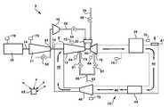
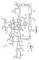
- FIG. 1is a schematic drawing illustrating an exemplary configuration of a power plant employing exhaust gas recirculation and a reheat combustion system
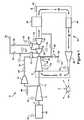
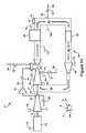
- FIG. 2is a schematic drawing illustrating an alternative configuration of a power plant employing exhaust gas recirculation and a reheat combustion system
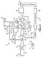
- FIG. 3is a schematic drawing illustrating an alternative configuration of a power plant employing exhaust gas recirculation and a reheat combustion system
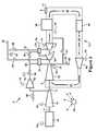
- FIG. 4is a schematic drawing illustrating an alternative configuration of a power plant employing exhaust gas recirculation and a reheat combustion system
- FIG. 5is a schematic drawing illustrating an alternative configuration of a power plant employing exhaust gas recirculation and a reheat combustion system
- FIG. 6is a schematic drawing illustrating an alternative configuration of a power plant employing exhaust gas recirculation and a reheat combustion system
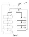
- FIG. 7is a flow diagram illustrating an exemplary method of operation relating to a power plant employing exhaust gas recirculation and a reheat combustion system
- FIG. 8is a schematic drawing illustrating an alternative configuration of a power plant employing exhaust gas recirculation and a reheat combustion system
- FIG. 9is a schematic drawing illustrating an alternative configuration of a power plant employing exhaust gas recirculation and a reheat combustion system
- FIG. 10is a schematic drawing illustrating a configuration of an alternative power plant employing exhaust gas recirculation and a single combustion system
- FIG. 11is a schematic drawing illustrating an alternative configuration of a power plant employing exhaust gas recirculation and a single combustion system
- FIG. 12is a schematic drawing illustrating an alternative configuration of a power plant employing exhaust gas recirculation and a single combustion system.
- FIG. 13is a schematic drawing illustrating an alternative configuration of a power plant employing exhaust gas recirculation and a single combustion system.
- FIGS. 1 through 13provided schematic illustrations of exemplary power plants according to configurations of the present application.
- these power plantsinclude novel system architectures and configurations and/or methods of control that achieve performance advantages given the recirculation of exhaust gases.
- the term “power plant”, as used herein,is not intended to be exclusionary and may refer to any of the configurations described herein, illustrated in the figures, or claimed.
- Such systemsmay include two separate turbines, exhaust gas recirculation, two combustion systems, and/or a heat-recovery steam generator.
- the power plant 9includes a recirculation loop 10 that includes a recirculating flow of working fluid.
- the recirculation loop 10is the means by which exhaust gas from the turbines recirculates, thereby creating a recirculating flow of working fluid.
- recirculation loop 10is configured such that each of the components positioned thereon are configured to accept an outflow of working fluid from a neighboring upstream component and provide an inflow of working fluid to a neighboring downstream component. Note that the several components of the recirculation loop 10 will be described in reference to a designated “start position 8 ” on the loop 10 .
- the start position 8is arbitrary and the function of the system could be described in another manner or in reference to another start position without substantive effect.
- the start position 8is positioned at the intake of an axial compressor 12 .
- the axial compressor 12accepts a flow of recirculated exhaust gases from the turbines; accordingly, the axial compressor 12 is referred to herein as “recirculation compressor 12 ”.
- the recirculation loop 10includes an upstream combustor 22 , which is associated with a high-pressure turbine 30 , and a downstream combustor 24 , which is associated with a low-pressure turbine 32 .
- upstream and downstreamdesignations generally refer to the direction of flow of working fluid through the recirculation loop 10 given the designated start position 8 .
- high-pressure and low-pressuredesignations are meant to refer to the operating pressure levels in each turbine 30 , 32 relative to the other given the position of each turbine on the recirculation loop 10 .
- recirculation conduit 40Downstream of the low-pressure turbine 32 , recirculation conduit 40 channels exhaust gases to the intake of the recirculation compressor 12 , which thereby recirculates the exhaust gases from the turbines (or, at least, a portion thereof).
- Several other componentsmay be positioned on the recirculation conduit 40 . It will be appreciated that these components may function to deliver the exhaust gases to the recirculation compressor 12 in a desired manner (i.e., at a desired temperature, pressure, humidity, etc.). As shown, in various embodiments, a heat recovery steam generator 39 , a cooler 44 , and a blower 46 may be included on the recirculation conduit 40 .
- the recirculation loop 10may include a recirculation vent 41 which provides a way to controllably vent an amount of exhaust from the recirculation conduit 40 such that a desirable flow balance is achieved.
- a recirculation vent 41which provides a way to controllably vent an amount of exhaust from the recirculation conduit 40 such that a desirable flow balance is achieved.
- an amount of exhaustmust be vented through the recirculation vent 41 that approximately equals the amount of compressed oxidant and fuel entering the recirculation loop 10 via the oxidant compressor 11 and fuel supply 20 , respectively.
- achieving a desired balance between oxidant/fuel injected into and exhaust vented from the recirculation loop 10may be done via sensors recording the amount of compressed oxidant and fuel entering the loop 10 and the amount of exhaust exiting, as well as, temperature sensors, valve sensors, pressure sensors within the recirculation loop 10 , and other conventional means and systems.
- the power plant 9may include an oxidant compressor 11 , which, unlike the recirculation compressor 12 , is not fully integrated into the recirculation loop 10 .
- the oxidant compressor 11may be an axial compressor that is configured to inject compressed air or other oxidant at one or more locations within the recirculation loop 10 . In most applications, the oxidant compressor 11 will be configured to compress air. It will be appreciated that, in other embodiments, the oxidant compressor 11 may be configured to supply any type of oxidant which could be pressurized and injected into the combustion system. For example, the oxidant compressor 11 could compress a supply of air doped with oxygen.
- the recirculation compressor 12is configured to compress recirculated exhaust gases from the turbines 30 , 32 .
- a booster compressor 16may be provided to boost the pressure of the discharge of the oxidant compressor 11 before it is injected into the recirculation loop 10 so that a preferable injection pressure is achieved. In this manner, the compressed oxidant may be effectively delivered to one or more combustors.
- the oxidant compressor 11 and the recirculation compressor 12may be mechanically coupled by a single or common shaft 14 that drives both.
- a generator 18may also be included on the common shaft 14 , while the high-pressure turbine 30 and the low-pressure turbine 32 drive the common shaft 14 and the loads attached thereto.
- the present inventionmay be employed in systems having shaft configurations different than the exemplary common shaft configuration 14 illustrated in the figures. For example, multiple shafts may be used, each of which may include one of the turbines and one or more of the load elements (i.e., one of the compressors 11 , 12 or the generator 18 ). Such a configuration may include concentric shafts or otherwise.
- the combustion system of the power plant 9includes an upstream combustor 22 and, downstream of that, a downstream combustor 24 .
- the upstream combustor 22 and the downstream combustor 24may include any type of conventional combustors, combustion systems and/or reheat combustors, and the chosen terminology refers only to relative positioning on the recirculation loop 10 (given the designated start position 8 and direction of flow).
- the chosen terminologyrefers only to relative positioning on the recirculation loop 10 (given the designated start position 8 and direction of flow).
- the upstream combustor 22operates by injecting into the recirculation loop 10 combustion gas resulting from a fuel being combusted in a can combustor or other type of conventional combustor.
- certain combustion systemsoperate by direct fuel injection.
- the injected fuelcombusts within the recirculation loop 10 .
- a fuel supply 20may supply fuel, such as natural gas, to the upstream combustor 22 and the downstream combustor 24 .
- the upstream combustor 22may be configured to accept the flow of compressed oxidant from the oxidant compressor 11 and a fuel from the fuel supply 20 .
- the upstream combustor 22may include one or more cans or combustion chambers within which fuel and oxidant are brought together, mixed, and ignited such that a high energy flow of pressurized combustion gases is created.
- the upstream combustor 22then may direct the combustion gases into the high-pressure turbine 30 , where the gases are expanded and work extracted.
- the downstream combustor 24may be configured to add energy/heat to the working fluid at a point downstream of the high-pressure turbine 30 . As shown in the embodiment of FIG.
- the downstream combustor 24may be positioned just upstream of the low-pressure turbine 32 .
- the downstream combustor 24is so-called because it adds heat/energy to the flow of working fluid at a point downstream of the upstream combustor 22 .
- the power plant 9further includes recirculation conduit 40 .
- the recirculation conduit 40in general, forms the flow path by which exhaust from the turbines is recirculated, thereby completing the recirculation loop 10 . More specifically, the recirculation conduit 40 directs the exhaust from the low pressure turbine 32 on a path that ends at the intake of the recirculation compressor 12 . It will be appreciated that the recirculation conduit 40 may circulate the exhaust through several components along the way, including, as indicated in FIG. 1 , a heat-recovery steam generator 39 , a cooler 44 , and a blower 46 . (Note that, to avoid unnecessary complexity, the heat-recovery steam generator 39 has been represented in a simplified form in FIG. 1 .) Those of ordinary skill in the art will appreciate that the heat-recovery steam generator 39 of the present invention may include any type of system in which combustion exhaust from one or more combustion turbines is used as the heat source for the boiler of a steam turbine.
- the cooler 44may be positioned such that gases flowing through the recirculation conduit 40 flow through it.
- the cooler 44may include a direct contact cooler or other conventional heat exchanger that suffices for this function, and may operate by extracting further heat from the exhaust gases such that the exhaust gases enter the recirculation compressor 12 at a desired or preferred temperature.
- the cooler 44may also provide means by which humidity levels within the recirculated gases is controlled to preferable levels. That is, the cooler 44 may extract water from the flow through cooling it, which thereby lowers the humidity level of the recirculated gases upon the gases being heated to the temperature of the flow before entering the cooler. As illustrated in FIG.
- the blower 46may be located downstream of the cooler 44 ; however, as one of ordinary skill in the art will appreciate, this order may be reversed.
- the blower 46may be of a conventional design.
- the blower 46may function to more efficiently circulate the exhaust gases through the recirculation conduit 40 such that the gases are delivered to the intake of the recirculation compressor 12 in a desired manner.
- the power plant 9may include several types of conduits, pipes, valves, sensors and other systems by which the operation of the power plant 9 is controlled and maintained. It will be appreciated that all valves described herein may be controlled to various settings that affect the amount of fluid passing through the conduit.
- the recirculation conduit 40recirculates exhaust gases from the turbines 30 , 32 to the intake of the recirculation compressor 12 , thereby providing a recirculating flow path for the working fluid.
- a first oxidant conduit 52may be provided that directs the compressed oxidant from the oxidant compressor 11 to the upstream combustor 22 .
- the first oxidant conduit 52may include an oxidant valve 54 that controls the flow of oxidant through this conduit.
- the first oxidant conduit 52further may include the booster compressor 16 , which, as described in more detail below, may be used to boost the pressure of the compressed oxidant within this conduit.
- the first oxidant conduit 52may further include a vent valve 56 .
- the vent valve 56provides means by which a portion of the compressed oxidant moving through the first oxidant conduit 52 is vented to atmosphere.
- certain embodiments of the present inventionoperate by providing a flow of compressed oxidant from the oxidant compressor 11 to the upstream combustor 22 , but not the downstream combustor 24 . In other embodiments, such as those shown in FIGS.
- the present inventionoperates by providing a flow of compressed oxidant from the oxidant compressor 11 to the upstream combustor 22 and the downstream combustor 24 .
- the present inventionoperates by providing a flow of compressed oxidant from the oxidant compressor 11 to the downstream combustor 22 but not the upstream combustor 24 .
- This type of systemfor example, is represented in FIGS. 2 and 4 when the oxidant valve 54 on the first oxidant conduit 52 is completely shut (i.e., set so that no flow from the oxidant compressor 11 is allowed to pass therethrough).
- the fuel supply 20may include two supply conduits that provide fuel to the upstream combustor 22 and/or the downstream combustor 24 .
- a fuel valve 58controls the amount of fuel being delivered to the upstream combustor 22
- another fuel valve 59controls the amount of fuel being delivered to the downstream combustor 24 .
- the fuel types delivered to the upstream combustor 22 and the downstream combustor 24do not have to be the same, and that the use of different fuel types may be advantageous given certain system criteria.
- the fuel valve 58 and the fuel valve 59may be controlled so that fuel is delivered to only one of the two combustors 22 , 24 .
- the fuel valve 58may be completely shut so that fuel is not delivered to the upstream combustor 22 .
- both combustors 22 , 24may operate per the fuel delivered to the downstream combustor 24 .
- the fuel valve 59may be completely shut so that fuel is not delivered to the downstream combustor 22 .
- both combustors 22 , 24may operate per the fuel delivered to the upstream combustor 22 . It will be appreciated that systems described herein as operating with a valve that is shut completely is intended to cover system configurations where the conduit on which the shut valve is positioned is omitted altogether.
- An extraction point 51comprises the point at which gases are extracted from the working fluid.
- the extraction point 51is positioned on the recirculation loop 10 such that carbon dioxide (CO 2 ) and/or nitrogen (N 2 ) may be efficiently extracted.
- CO 2carbon dioxide
- N 2nitrogen
- the system architecture of the present inventionallows for such extraction to occur at a position that, as illustrated in FIG. 1 , is upstream of both the high-pressure turbine 30 and the upstream combustor 22 . More specifically, as shown, the extraction point 51 may be located at a position that is just upstream of the combustion reaction in the upstream combustor 22 .
- the extraction point 51may include conventional extracting means by which a portion of the gases within the working fluid are diverted into a conduit and, thereby, removed from the recirculation loop 10 .
- An extracted gas valve 61may be provided to control the amount of working fluid that is extracted. Downstream of the extracted gas valve 61 , the conduit may deliver an extracted gas supply 62 to one or more downstream components (not shown).
- the extracted gas supply 62may be directed to a separation system (not shown) that separates the carbon dioxide from the nitrogen per conventional means. As stated, after separation, these gases may be used in many types of industrial applications, such as, for example, applications in the food and beverage industry.
- a turbine bypass conduit 63also may be included that provides a pathway that bypasses each of the turbines 30 , 32 .
- the turbine bypass conduit 63is provided for startup situations, and, because it does not meaningfully impact the function of the present invention, will not be discussed further.
- the extraction point 51may be located in different locations within the recirculation loop 10 of FIG. 1 .
- the architecture and control methods provided hereinteach efficient and effective means by which one of the combustors 22 , 24 may be operated at or near the stoichiometric point or a preferred stoichiometric ratio. That is, the fuel and oxidant supply within the power plant 9 may be controlled in such a way that, once the oxidant and fuel have adequately mixed, ignited and combusted within one of the combustors 22 , 24 , an exhaust that is free or substantially free of oxygen and unspent fuel is produced.
- the exhaustconsists of high levels of carbon dioxide and nitrogen, which may be economically extracted for use in other applications.
- “operation at the stoichiometric point” or “stoichiometric point operation”refers to operation at, near or within an acceptable or desired range about the stoichiometric point.
- “stoichiometric point”may also be referred to a stoichiometric ratio of 1, as it is said to include a 1-to-1 ratio of fuel and oxidant. It will further be appreciated that ratios that are greater than 1 are described as containing excess oxidant, while ratios less than 1 are described as containing excess fuel.
- stoichiometric point operationmay refer to stoichiometric operation within a range about the stoichiometric point or, put another way, a stoichiometric ratio of 1. Accordingly, in certain embodiments, “stoichiometric point operation” may refer to operation within the range of stoichiometric ratios defined between 0.75 and to 1.25. In more preferable embodiments, “stoichiometric point operation” may refer to operation within the range of stoichiometric ratios defined between 0.9 and to 1.1.
- “stoichiometric point operation”may refer to operation that is substantially at or very close to a stoichiometric ratio of 1.
- “stoichiometric point operation”may refer to operation within the range of stoichiometric ratios defined between approximately 1.0 and to 1.1.
- the exhaust downstream of the combustoris substantially devoid of unspent fuel and oxygen, and consists substantially of carbon dioxide and nitrogen gas (and/or some other desirable gaseous characteristic), which may be economically extracted.
- the extraction point 51generally may be located at any point on the recirculation loop 10 that is both: 1) downstream of the whichever combustor 22 , 24 is operating at the stoichiometric point and 2) upstream of the other combustor 22 , 24 .
- upstream of the other combustormeans upstream of the point within the combustor at which oxidant and/or fuel actually enters the recirculation loop 51 , and that, because of this, “upstream of the other combustor” may include areas that might be construed as within the “other combustor” but which are also upstream of the position at which oxidant and/or fuel is injected into the flow of working fluid, such as, for example, certain areas within a combustor head-end. In a configuration like FIG.
- the extraction point 51may be located at any point within a range defined between the downstream combustor 24 and, proceeding in a downstream direction, the upstream combustor 22 . In one preferred embodiment, as illustrated in FIG. 1 , the extraction point may be located within this range at the discharge of the recirculation compressor 12 . It will be appreciated that this location provides extracted gas that is highly pressurized, which may be advantageous in certain downstream uses.
- the power plant 9may further include one or more sensors 70 that measure operating parameters, settings, and conditions within the components and various conduits of the system.
- One such sensormay be a sensor for detecting excess oxidant 64 , such as, for example, a conventional oxygen sensor.
- the sensor for detecting excess oxidant 64may be positioned just upstream of the extraction point 51 and may measure at predefined intervals the oxygen content of the exhaust or working fluid flowing through the recirculation loop 10 .
- the sensor for detecting excess oxidant 64may be well situated to test the working fluid for oxidant content, which may provide information as to stoichiometric ratio within the combustor directly upstream of the sensor for detecting excess oxidant 64 and/or whether extraction of the working fluid would yield a gas supply that is suitably free of oxidant and unspent fuel. It will be appreciated that the sensor for detecting excess oxidant 64 may be positioned within a range on the recirculation loop 10 that is defined between the extraction point 51 and, proceeding in the upstream direction, the first combustor 22 , 24 that is encountered.
- the first combustor 22 , 24 encountered in the upstream directionis the combustor 22 , 24 which is being controlled at the preferred stoichiometric ratio.
- the sensor for detecting excess oxidant 64may be used to determine the current desirability of extracting gas from the recirculation loop 10 .
- the systemmay include other sensors 70 that measure a host of process variables that may relate to any of the components of the system. Accordingly, the figures indicate a plurality of sensors 70 at exemplary locations about the power plant 9 .
- conventional systemstypically include many sensors other than just those represented in the several figures, and, further, that those other sensors may be located in other locations within the system than just those indicated. It will be appreciated that these sensors 70 may electronically communicate their readings with the control unit 65 and/or function pursuant to instructions communicated to them by the control unit 65 .
- One such sensor 70 that could be used either together or interchangeably with the sensor for detecting excess oxidant 64is a sensor that detects the presence of unspent fuel in the exhaust.
- an unspent fuel sensor 70could provide measurements from which the stoichiometric ratio in the upstream combustor 22 , 24 could be determined as well as the current suitability of extracting working fluid.
- sensorsmay be used to collect data concerning the stoichiometric properties of the combustion occurring within the combustors. For example, a CO sensor and a humidity sensor may be used.
- the power plant 9may further include a control unit 65 that functions according to certain embodiments described herein.
- the control unit 65may include an electronic or computer implemented device that takes in data from sensors and other sources regarding plant operational parameters, settings, and conditions, and, pursuant to algorithms, stored data, operator preferences, etc., controls the settings of the various mechanical and electrical systems of the power plant 9 such that desired modes of operation are achieved.
- the control unit 65may control the power plant 9 such that stoichiometric operation or operation at a preferred stoichiometric ratio is achieved in one of the combustors 22 , 24 .
- control mechanismmay achieve this objective by balancing the fuel and oxidant injected into the either the upstream or downstream combustor 22 , 24 , as well as taking into account any excess oxidant or unspent fuel from the other of the two combustor 22 , 24 that travels within the recirculating working fluid.
- control unit 65may control the extracted gas valve 61 such that extraction takes place at a desired rate and for a desired period of time or until changing conditions make the extraction no longer suitable.
- the settings of the various valves described above that govern the flow of working fluid, extraction of gases, fuel consumption, etc.may be controlled pursuant to electrical signals, which may be sent via wired or wireless communication connections, received from the control unit 65 .
- the power plant 9may operate as follows.
- the rotation of blades within oxidant compressor 11compresses oxidant that is supplied, via the first oxidant conduit 52 to the upstream combustor 22 .
- the booster compressor 16may be provided in some embodiments.
- the booster compressor 16may be used to increase the pressure of the oxidant being supplied by the oxidant compressor 11 to a level that is adequate or preferable for injection into the upstream combustor 22 .
- the flow of compressed oxidantmay be joined within the upstream combustor 22 with a flow of compressed exhaust gases, which is supplied to the combustor from the recirculation compressor 12 .
- the upstream combustor 22may be configured to combine the flow of compressed oxidant from the oxidant compressor 11 with the flow of compressed exhaust gases from the recirculation compressor 12 and combust a fuel therein, producing a flow of high-energy, pressurized combustion gases.
- the flow of combustion gasesthen is directed over the stages of rotating blade within the high-pressure turbine 30 , which induces rotation about the shaft 14 .
- the shaft 14may couple the high-pressure turbine 30 to the oxidant compressor 11 so that the rotation of the shaft 14 drives the oxidant compressor 11 .
- the shaft 14further may couple the high-pressure turbine 30 to the recirculation compressor 12 so that the rotation of the shaft 14 drives the recirculation compressor 12 .
- the shaft 14also may couple the high-pressure turbine 30 to the generator 18 so that it drives the generator 18 as well. It will be appreciated that the generator 18 converts the mechanical energy of the rotating shaft into electrical energy. Of course, other types of loads may be driven by the high-pressure turbine 30 .
- the working fluidi.e., the exhaust from the high-pressure turbine 30
- the downstream combustor 24adds heat/energy to the working fluid flowing through the recirculation loop 10 , as described above.
- the downstream combustor 24is configured to combust a fuel within the exhaust from the high-pressure turbine 30 .
- the downstream combustor 24may be configured to combine a flow of compressed oxidant from the oxidant compressor with the flow of exhaust gases from the high-pressure turbine 30 and combust a fuel therein, producing a flow of high-energy, pressurized combustion gases.
- the working fluidthen is directed over the stages of rotating blades within the low-pressure turbine 32 , which induces rotation about the shaft 14 , thereby transforming the energy of the combustion gases into the mechanical energy of the rotating shaft 14 .
- the shaft 14may couple the low-pressure turbine 32 to the oxidant compressor 11 , the recirculation compressor 12 , and/or the generator 18 .
- the high-pressure turbine 30 and the low-pressure turbine 32may drive these loads in tandem.
- concentric shaftsmay be used such that the high-pressure turbine 30 drives part of the load on one of the concentric shafts, while the low-pressure turbine 32 drives the remaining load on the other.
- the high-pressure turbine 30 and the low-pressure turbine 32may drive separate, non-concentric shafts (not shown).
- recirculation conduit 40may form a flow path that completes the recirculation loop 10 of the present invention. This flow path, ultimately, delivers the exhaust gases from the turbines 30 , 32 to the intake of the recirculation compressor 12 .
- the exhaust gasesmay be used by the heat-recovery steam generator 39 . That is, the exhaust gases may provide a heat source for the boiler that drives a steam turbine which receives steam from the heat-recovery steam generator 39 . Downstream of that, the exhaust gases may be further cooled by the cooler 44 as well as being passed through a blower 46 .
- the cooler 44may be used to lower the temperature of the exhaust gases so that they are delivered to the intake of the recirculation compressor 12 within a desired temperature range.
- the blower 46may assist in circulating the exhaust gases through the recirculation loop 10 . It will be appreciated that the heat recovery steam generator 39 , the cooler 44 and the blower 46 may include conventional components and be operated pursuant to conventional methods.
- control unit 65may include an electronic or computer implemented device that takes in data regarding plant operational parameters and conditions, and, pursuant to algorithms, stored data, operator preferences, etc., controls the settings of the various mechanical and electrical systems of the power plant 9 such that desired modes of operation are achieved—for example, achieving operation at or substantially at the stoichiometric point.
- the control unit 65may include control logic specifying how the mechanical and electrical systems of the power plant 9 should operate. More specifically, and in accordance with certain embodiments of the present application, the control unit 65 typically includes programmed logic that specifies how certain operating parameters/stored data/operator preferences/etc.
- the control unit 65may control the operation of the various systems and devices automatically in response to the dictates of the control logic, or, in certain instances, may seek operator input before actions are taken.
- a systemmay include multiple sensors, devices, and instruments, some of which are discussed above, that monitor relevant operational parameters. These hardware devices may transmit data and information to the control unit 65 , as well as being controlled and manipulated by the control unit 65 .
- control unit 65may receive and/or acquire data from the systems of the power plant 9 , process the data, consult stored data, communicate with the operators of the power plant 9 , and/or control the various mechanical and electrical devices of the system pursuant to a set of instructions or logic flow diagrams, which, as one of ordinary skill in the art will appreciate, may be made part of a software program that is operated by control unit 65 , and which may include aspects relating to embodiments of the present invention.
- the control unit 65may control operation of the power plant 9 such that it operates at the stoichiometric point and, while operating thusly, extracts a supply of combustion exhaust that is substantially devoid of oxygen and unspent fuel. Discussion below, in relation to FIG. 7 , relates to logic flow diagrams according to the present invention for operating the systems described herein at the stoichiometric point and extraction of desirable exhaust gas. It will be appreciated that these logic flow diagrams may be used by the control unit for such purposes.
- FIGS. 2 through 6provide embodiments of the present invention that include alternative system configurations. It will be appreciated that these configurations present alternative strategies for injecting oxidant from the oxidant compressor 11 into the recirculation loop 10 , delivering fuel to the combustion systems, and the manner in which exhaust gases may be extracted. Each of these alternatives offers certain advantages, including the manner in which stoichiometric operation may be achieved and maintained. It will be appreciated that these alternatives are exemplary and not intended to provide an exhaustive description of all possible system configurations which might fall within the scope of the appended claims. In addition, while FIGS.
- FIG. 2 through 4provide embodiments that include a second oxidant conduit 67 and oxidant valve 68 , which together may be used to supply a controlled compressed oxidant amount (which like the first oxidant conduit 52 is derived from the oxidant compressor 11 ) to the downstream combustor 24 .
- the second oxidant conduit 67may branch from the first oxidant conduit 52 , which means that the compressed oxidant for each is drawn from the same supply point from the oxidant compressor 11 .
- the branchingoccurs such that a connection with the first oxidant conduit 52 occurs upstream of the oxidant valve 54 and booster compressor 16 of the first oxidant conduit 52 .
- the second oxidant conduit 67thereby bypasses the booster compressor 16 .
- Thismay be useful in creating flows of differing pressures levels within the first oxidant conduit 52 , which would have a higher pressure due to the booster compressor 16 than that within the second oxidant conduit 67 .
- the first oxidant conduit 52provides compressed oxidant to a point on the recirculation loop 10 upstream of the second oxidant conduit 67 .
- this configurationallows for an efficient means by which the pressure in each may be controlled to a pressure level that is appropriate for injection at the different locations.
- the branchingoccurs downstream of the oxidant valve 54 of the first oxidant conduit 52 . More specifically, the branching of the second oxidant conduit 52 occurs between the oxidant valve 54 of the first oxidant conduit 52 (which may be positioned downstream of the booster compressor 16 , as shown) and combustor 22 .
- the second oxidant conduit 67may also be independent of the first oxidant conduit 52 .
- the second oxidant conduit 67may extend from an extraction point within the oxidant compressor 11 .
- the extraction point for the second oxidant conduitmay be located at one of the stages that is upstream of the position where the first oxidant conduit 52 derives its flow of compressed oxidant, which, for example, may be located in the compressor discharge casing. More specifically, the extraction point may be configured to bleed compressed oxidant at an intermediate stage within the oxidant compressor 11 .
- this arrangementresults in a higher pressure flow of compressed oxidant through the first oxidant conduit 52 than that in the second oxidant conduit 67 . It again will be appreciated that this configuration allows the first and second oxidant conduits 52 , 67 to have differing pressure levels without the need of including a booster compressor 16 . As before, the pressure differential may be useful in that the pressure of the compressed oxidant may be matched to the pressure at the position on the recirculation loop 10 it is used.
- FIGS. 5 and 6provide differing strategies for locating the extraction point 51 given the fact that both combustors 22 , 24 receive a supply of compressed oxidant from the oxidant compressor 11 .
- configuring the system to have two points at which oxidant/fuel are combustedprovides new alternatives for producing operation at the stoichiometric point (note that, as stated, this refers to operation within a desired range about or near the stoichiometric point), and, thus, differing locations (as provided in FIGS. 5 and 6 ) at which working fluid may be extracted.
- the architecture and control methods provided hereinteach efficient and effective means by which power plants may be operated at the stoichiometric point.
- the fuel and oxidant supply to the power plant 9may be controlled in such way that, once the oxygen (from the injected oxidant) and fuel have adequately mixed, ignited and combusted, an exhaust that is substantially free of oxygen and unspent fuel is produced.
- the extraction point 51may be located at any point on the recirculation loop 10 that has exhaust derived from stoichiometric point operation. As described above in relation to the configuration of FIG.
- FIG. 5illustrates an exemplary configuration having an extraction point 51 that is positioned near the aft end of the high-pressure turbine 30 . It will be appreciated that this extraction point 51 may prove effective when the upstream combustor 22 operates at the stoichiometric point. Given the principles discussed above and assuming this operation, possible extraction points 51 constitute a range defined between the upstream combustor 22 and, proceeding in the downstream direction, the downstream combustor 24 .
- the power plant 9may be controlled such that the combined effect of the oxidant and fuel introduced within the combustors 22 , 24 produces combustion within the upstream combustor 22 at a preferred stoichiometric ratio, which thereby creates a range of positions downstream of the upstream combustor 22 in which extraction of working fluid having desired characteristics may be achieved.
- FIG. 6illustrates an exemplary configuration having an extraction point 51 that is positioned just upstream of the heat recovery steam generator 39 . It will be appreciated that this extraction point 51 may prove effective when the downstream combustor 24 operates at the stoichiometric point. Given the principles discussed above and assuming this operation, possible extraction points 51 constitute a range defined between the downstream combustor 24 and, proceeding in the downstream direction, the upstream combustor 22 .
- the power plant 9may be controlled such that the combined effect of the oxidant and fuel introduced within the combustors 22 , 24 produces combustion within the downstream combustor 24 at a preferred stoichiometric ratio, which thereby creates a range of positions downstream of the downstream combustor 24 in which extraction of the working fluid having desired characteristics may be achieved.
- FIG. 7illustrates a logic flow diagram 100 for a method of operating the power plant 9 according to an exemplary embodiment of the present invention.
- the logic flow diagram 100is exemplary and includes steps which may not be included in the appended claims. Further, any function described above in relationship to the several components of the system is incorporated into the discussion below where necessary or possible to aid in the carrying out of the specified steps.
- the logic flow diagram 100may be implemented and performed by the control unit 65 .
- the control unit 65may comprise any appropriate high-powered solid-state switching device.
- the control unit 65may be a computer; however, this is merely exemplary of an appropriate high-powered control system, which is within the scope of the present application.
- control unit 65may be implemented as a single special purpose integrated circuit, such as ASIC, having a main or central processor section for overall, system-level control, and separate sections dedicated to performing various different specific combinations, functions and other processes under control of the central processor section. It will be appreciated by those skilled in the art that the control unit also may be implemented using a variety of separate dedicated or programmable integrated or other electronic circuits or devices, such as hardwired electronic or logic circuits including discrete element circuits or programmable logic devices.
- the control unit 65also may be implemented using a suitably programmed general-purpose computer, such as a microprocessor or microcontroller, or other processor device, such as a CPU or MPU, either alone or in conjunction with one or more peripheral data and signal processing devices. In general, any device or similar devices on which a finite state machine capable of implementing the logic flow diagram 100 may be used as the control unit 65 .
- control unit 65may include a General Electric SPEEDTRONICTM Gas Turbine Control System, such as is described in Rowen, W. I., “SPEEDTRONICTM Mark V Gas Turbine Control System”, GE-3658D, published by GE Industrial & Power Systems of Schenectady, N.Y.
- the control unit 65may be a computer system having a processor(s) that executes programs to control the operation of the gas turbine using sensor inputs and instructions from human operators.
- the programs executed by the control unit 65may include scheduling algorithms for regulating the components of the power plant 9 .
- the commands generated by the control unit 65may cause actuators within any of the components to, for example, adjust valves between the fuel supply and combustors 22 , 24 that regulate the flow and type of fuel, inlet guide vanes on the compressors 11 , 12 , and other control settings on the turbine 30 , 32 .
- the control unit 65may regulate the power plant 9 based, in part, on algorithms stored in computer memory of the control unit 65 . These algorithms, for example, may enable the control unit 65 to maintain emission levels in exhaust to within certain predefined limits, to maintain the combustor firing temperature to within predefined temperature limits, or another maintain operational parameter within a predefined range.
- flow diagram 100illustrates an example of how a feedback loop may be structured to provide an iterative process for controlling stoichiometry within one of the combustors and/or extraction level of exhaust having desired characteristics. It will be appreciated that the several steps of such a process may be described in many different ways without deviating from the central idea of the process set forth herein.
- the control methods described hereinmay be implemented via a feedback loop that is used in conjunction with control algorithms, such as a PID control algorithm, though other control algorithms also may be used.
- Logic flow diagram 100may begin at a step 102 , which includes monitoring and measuring the operating conditions and process variables (which will be referred to generally as “process variables”) of the power plant 9 .
- Process variablesrepresent the current status of the system or process that is being controlled. In this case, process variables may include any operating parameter that may be measured by any type of sensor.
- the control unit 65pursuant to any of the methods discussed above or any conventional systems (either current or developed in the future), may receive, monitor, and record data relating to the operation of the power plant 9 .
- the operation of the power plant 9 and the several components related theretomay be monitored by several sensors 70 detecting various conditions of the system and environment.
- one or more of the following process variablemay be monitored by the sensors 70 : temperature sensors may monitor ambient temperature surrounding the plant 9 , inlet and discharge temperatures of the compressors 11 , 12 , exhaust temperature and other temperature measurements along the hot-gas path of the turbines 30 , 32 , pressure sensors may monitor ambient pressure, and static and dynamic pressure levels at the inlet and outlet of the compressors 11 , 12 , and exhaust of the turbines 30 , 32 , as well as at other locations in the gas stream.
- Sensors 70further may measure the extraction level at the extraction point 51 , fuel flow to each of the combustors 22 , 24 , gas composition within the recirculated exhaust gas or working fluid (which may include sensor for detecting excess oxidant 64 as well as other sensors that measure levels of unspent fuel or CO or other gases within the exhaust gas), temperature and pressure of the recirculated exhaust gas along the recirculation conduit 10 , including parameters relating to the operation of the heat recovery steam generator 39 , the cooler 44 , and the blower 46 .
- gas composition within the recirculated exhaust gas or working fluidwhich may include sensor for detecting excess oxidant 64 as well as other sensors that measure levels of unspent fuel or CO or other gases within the exhaust gas
- temperature and pressure of the recirculated exhaust gas along the recirculation conduit 10including parameters relating to the operation of the heat recovery steam generator 39 , the cooler 44 , and the blower 46 .
- the sensors 70may also comprise flow sensors, speed sensors, flame detector sensors, valve position sensors, guide vane angle sensors, and the like that sense various parameters pertinent to the operation of power plant 9 , which may include oxidant flow characteristics through the first oxidant conduit 52 and the second oxidant conduit 67 . It will be appreciated that the system may further store and monitor certain “specified set-points” that include operator preferences relating to preferred or efficient modes of operation. It further will be appreciated that the measuring, monitoring, storing and/or recording of process variables and/or specified set-point may occur continuously or at regular intervals, and that updated or current data may be used throughout any of the several steps of logic flow diagram 100 whether or not there is a direct line in FIG. 7 connecting step 102 to the other steps. From step 102 , the process may continue to step 104 .
- the methodmay determine whether whichever combustor 22 , 24 is configured to operate at a preferred stoichiometric ratio (which may include a range of suitable stoichiometric ratios) is, in fact, operating at the preferred stoichiometric ratio. It will be appreciated that this may be accomplished by comparing measured process variables, calculating current conditions, and comparing current conditions to specified set-points. If it is determined that this mode of operation is occurring, the method may proceed to step 106 . If it is determined that this mode of operation is not occurring, the method may proceed to step 114 .
- a preferred stoichiometric ratiowhich may include a range of suitable stoichiometric ratios
- the determination as to whether the relevant combustor 22 , 24 is operating at the preferred stoichiometric ratiomay be achieved in several ways and that, once determined, a feedback loop using one or more control inputs may be used to control the system within this preferred mode or cause the system to operate in this manner.
- One methodmay be to detect or measure the content of the exhaust gases being emitted from the relevant combustor. This may include sensors 70 , such as the sensor for detecting excess oxidant 64 , that measures the gases present in the exhaust and/or other relevant characteristics. It will be appreciated that a sensor 70 that detects the presence of unspent fuel or CO or other gases within the exhaust flow may be used also.
- Measuring the flow characteristics of the inputs (i.e., the oxidant and the fuel) to one of the combustorsalso may be used to determine if combustion within the relevant combustor is occurring at the preferred stoichiometric ratio.
- the oxidant flow into the combustormay be measured
- the fuel flow into the combustormay be measured
- Other relevant operating characteristicssuch as temperature, pressure, etc.
- unspent fuel or CO or other gases and/or oxygenmay be measured downstream of the combustors or other points within the circulating flow of working fluid. From this, a calculation may be made as to the stoichiometric balance of the combustion, which may then be compared with the specified set-point or preferred stoichiometric ratio to determine if it falls within an acceptable range.
- the logic flow diagram 100may determine the current level of extraction at extraction point 51 . This may be done via checking measured process variables which either indicate this flow level directly or may be used to calculate the amount of gas being extracted. The method may further check whether the current level of extraction satisfies a desired level of extraction or specified set-point. This may be done by comparing the actual level of extraction (which may be measured) to operator defined set-points or preference. If it is determined that the desired level of extraction is being satisfied, the method may cycle back to step 102 where the process begins anew. If it is determined that the desired level of extraction is not being satisfied, the method may proceed to step 108 .
- the methoddetermines one or more “control inputs” that may be used to manipulate the function of system components in such a way as to achieve the desired level of extraction or, at least, to achieve an extraction level that decreases the difference between the actual level of extraction and the desired level of extraction.
- a “control input”is one of the many ways by which operation of the power plant 9 or any of its components may be controlled or manipulated. These, for example, may include level of fuel flow to the combustors 22 , 24 , control of oxidant flow to the combustors 22 , 24 , angle of inlet guide vanes within the compressors 11 , 12 , etc.
- a “variance amount”is the extent to which a control input must be manipulated to bring about the desired manner of operation.
- the variance amountmay include the extent to which the fuel flow to the combustors 11 , 12 must be increased or decreased to bring about desired operation.
- one of the control inputs that is particularly relevant at step 108is the setting of the extracted gas valve 61 .
- the variance amountis the extent to which the setting of the valve 61 needs to be manipulated so that a desired extraction level is achieved.
- the methodmay then proceed to step 110 .
- a conventional feedback control mechanism in conjunction with a PID controller or the likemay be used to achieve control as specified herein.
- an iterative process of variations to one or more control inputsmay bring the system toward desired operation.
- the methodmay determine the probable effects to plant operation of each of the available control inputs/variance amounts from step 108 before making the actual change to the control input. It will be appreciated that these types of calculations may be achieved per conventional power plant control programs and modeling software, such as those systems and methods mention herein and others similar to them. It further will be appreciated that these calculations may involve an iterative process that takes into account efficient control measures/counter-measures which may be made in response to the proposed variance of the relevant control input, economic considerations, wear and tear to the power plant, operator preferences, plant operational boundaries, etc. The method then may proceed to Step 112 .
- the process 100may determine which of the available control inputs/variance amounts from the above step is most favorable or preferred. This determination, in large part, may be based upon the effects to system operation that were calculated in step 110 . Then, for whichever control input/variance amount is deemed most favorable, the method may determine if the proposed control input/variance amount should be executed based on whether the associated benefits of meeting extraction demand outweighs the costs associated with executing the variance amount. It will be appreciated that economic considerations and operator preferences may be included in this determination. Based on this calculation, the method then may execute the proposed control input/variance amount or not. The method then may return to step 102 , and an iterative process begun by which a preferred level of extraction is achieved.
- control inputsinclude ways in which operation of the power plant 9 may be altered, manipulated or controlled, and the variance amount is the extent to which a control input must be manipulated to achieve a desired mode of operation. The method may then proceed to step 116 .
- the methodmay determine the probable effects to plant operation of each of the available control inputs/variance amounts from step 114 . It will be appreciated that these types of calculations may be achieved per conventional power plant control programs and modeling software, such as those systems and methods mention herein and others similar to them. It further will be appreciated that these calculations may involve an iterative process that takes into account efficient control measures/counter-measures which may be made in response to the proposed variance of the relevant control input, economic considerations, wear and tear to the power plant, operator preferences, plant operational boundaries, etc. The method then may proceed to Step 118 .
- Plant operation boundariesmay include any prescribed limit that must be followed so that efficient operation is achieved and/or undue wear and tear or more serious damage to systems is avoided.
- operational boundariesmay include maximum allowable temperatures within the turbines 30 , 32 or combustor components. It will be appreciated that exceeding these temperatures may cause damage to turbine components or cause increased emissions levels.
- Another operational boundaryincludes a maximum compressor pressure ratio across each of the oxidant compressor 11 and the recirculation compressor 12 . Exceeding this limitation may cause the unit to surge, which may cause extensive damage to components.
- the turbinemay have a maximum mach number, which indicates the maximum flow rate of the combusted gases at the exit of the turbine. Exceeding this maximum flow rate may damage turbine components.
- relative pressures of the flows delivered at the combustors 22 , 24 by each of the compressors 11 , 12may be another operational boundary. That is, depending on the configuration of the combustor 22 , 24 and the manner in which flows are combined, the pressure of the compressed oxidant delivered by the oxidant compressor 11 must be within a certain range of that supplied by recirculation compressor 12 to avoid aerodynamic losses, backflow, and other potential issues.
- the methodmay determine which of the available control inputs/variance amounts from the above step is most favorable or preferred. This determination, in large part, may be based upon the effects to system operation that were calculated in step 116 as well as the extent to which the control input/variance amount is able to manipulate the power plant system toward the intended mode of operation. Then, for whichever control input/variance amount is deemed most favorable, the method may determine if the proposed control input/variance amount should be executed based on whether the associated benefits of achieving stoichiometric point operation (which may include the benefits of being able to extract working fluid) outweighs the costs associated with executing the variance amount. It will be appreciated that economic considerations and operator preferences may be included in this determination.
- the methodthen may execute the proposed control input/variance amount or not.
- the methodthen may return to step 104 , and an iterative process by which stoichiometric point operation within one of the combustors is ultimately achieved or determined not possible due to some operational constraint.
- control inputs/variance amountsthat affect the stoichiometric ratio in the combustors 22 , 24 .
- one such control inputincludes controllably varying the compressed oxidant amount delivered to the combustors 22 , 24 . It will be appreciated that controllably varying the supply of compressed oxidant may have a significant effect on the stoichiometry ratio within the combustors 22 , 24 .
- the supply of compressed oxidantmay be increased by manipulating inlet guide vanes of the oxidant compressor 11 and/or changing valve settings on the oxidant valves 54 , 68 so that more compressed oxidant is able to pass through the oxidant conduit 52 , 67 associated with the combustor.
- varying fuel supplyis another control input that may be used to achieve operation at a preferred stoichiometric ratio.
- sensors 70may indicate that, given the compressed oxidant amount being delivered to the combustor, more fuel is needed to achieve stoichiometric point operation.
- the fuel amount being delivered to the one or both combustors 22 , 24may be increased by manipulating one or both of the fuel valves 58 , 59 .
- stoichiometric point combustionmay be controlled in one of the combustors by changing settings that are directly related to the other combustor. This is because changed settings within one combustor may create excess oxidant or unspent fuel in the recirculation loop 10 that is ultimately ingested within the other combustor, thereby affecting the combustion stoichiometric ratio therein.
- the fuel/oxidant input into the power plant 9may be set such that there is excess oxidant (i.e., a stoichiometric ratio greater than 1) in whichever of the combustors 22 , 24 is meant to operate at the stoichiometric point. Then, the control process may decrease the excess oxidant by small increments within the relevant combustor 22 , 24 (either by increasing fuel flow to the combustor or by decreasing the oxidant supply) while monitoring the stoichiometric ratio therein by measuring a relevant process variable. In certain embodiments, this may continue until the stoichiometric ratio is within a preferred range, while still being slightly above 1 (i.e., still having excess oxidant).
- excess oxidanti.e., a stoichiometric ratio greater than 1
- Thismay be implemented by slowly increasing oxidant flow, decreasing fuel flow, or both to the particularly combustor 22 , 24 , while monitoring stoichiometric conditions therein. It may also be done indirectly by slowly increasing oxidant flow, decreasing fuel flow, or both to the other combustor 22 , 24 so that excess fuel or oxidant becomes part of the working fluid and ingested into the relevant combustor.
- FIGS. 8 and 9provide schematic illustrations of alternative configurations of exemplary power plants according to the present application. As shown, these power plants also employ exhaust gas recirculation and a reheat combustion system similar to those described above. However, the power plants of FIGS. 8 and 9 provide dual extraction locations on the recirculation loop. It will be appreciated that while the description of components, system configurations, and control methods provided above are applicable to the power plants of FIGS. 8 and 9 (as well as some of the functionality described below being applicable to the components, system configuration, and control methods described above), the dual extraction locations provide a novel application that enables enhanced functionality, which may beneficially employed in certain operating conditions. As before, the power plant 9 may include a recirculation loop 10 about which a working fluid is recirculated.
- the recirculation loop 10may include a plurality of components that are configured to accept an outflow of working fluid from a neighboring upstream component and provide an inflow of working fluid to a neighboring downstream component.
- the components of the recirculation loop 10may include: a recirculation compressor 12 ; an upstream combustor 22 positioned downstream of the recirculation compressor 12 ; a high-pressure turbine 30 positioned downstream of the upstream combustor 22 ; a downstream combustor 24 positioned downstream of the high-pressure turbine 30 ; a low-pressure turbine 32 positioned downstream of the downstream combustor 24 ; and recirculation conduit 40 configured to complete the loop by directing the outflow of working fluid from the low-pressure turbine 32 to the recirculation compressor 12 .
- the power plant 9 of FIGS. 8 and 9may further include systems and components that control and deliver a compressed oxidant amount to each of the upstream combustor and the downstream combustor. As described above in relation to the other exemplary power plants 9 , the power plant 9 of FIGS. 8 and 9 may further include systems and components that control a fuel amount supplied to each of the upstream combustor 22 and the downstream combustor 24 .
- the power plant 9may further include systems and components that extract the working fluid exhausted from the upstream combustor 22 from a first extraction point 75 , and systems and components that extract the working fluid exhausted from the downstream combustor 24 from a second extraction point 76 .
- the power plant 9may include systems and components for controlling operation such that each of the upstream combustor 22 and the downstream combustor 24 periodically operate at a preferred stoichiometric ratio, as well as means for selectively extracting working fluid from the first extraction point 75 and the second extraction point 76 based on which of the upstream combustor 22 and the downstream combustor 24 operates at the preferred stoichiometric ratio.
- the first extraction point 75may include a first controllable extracted gas valve 61 for controlling the amount of gas extracted at that location.
- the first extraction point 75may be disposed on the recirculation loop 10 between the upstream combustor 22 and, proceeding in a downstream direction, the downstream combustor 24 .
- one exemplary location for the first extraction point 75is the aft end of the high-pressure turbine 30 .
- the first controllable extracted gas valve 61may be controllable to at least two settings: a closed setting that prevents the extraction of working fluid and an open setting that allows the extraction of working fluid.
- the second extraction point 76may include a second controllable extracted gas valve 61 for controlling the amount of gas extracted at that location.
- the second extraction point 76may be disposed on the recirculation loop 10 between the downstream combustor 24 and, proceeding in a downstream direction, the upstream combustor 22 .
- one exemplary location for the second extraction point 76is the aft end of the low-pressure turbine 32 .
- another exemplary location for the second extraction point 76is on the recirculation conduit 40 between the cooler 44 and the blower 46 .
- the second controllable extracted gas valve 61may be controllable to at least two settings: a closed setting that prevents the extraction of working fluid and an open setting that allows the extraction of working fluid.
- the systems and components for controlling the compressed oxidant amount supplied to the upstream combustor 22may include an oxidant compressor 11 , a first oxidant conduit 52 that is configured to direct compressed oxidant derived from the oxidant compressor 11 to the upstream combustor 22 , and a first controllable oxidant valve 54 disposed on the first oxidant conduit 52 that is controllable to at least three settings: a closed setting that prevents delivery of the compressed oxidant to the upstream combustor 22 and two open settings that allow delivery of differing compressed oxidant amounts to the upstream combustor 22 .
- the systems and components for controlling the compressed oxidant amount supplied to the downstream combustor 24may include the oxidant compressor 11 , a second oxidant conduit 67 that is configured to direct compressed oxidant derived from the oxidant compressor 11 to the downstream combustor 24 , and a second controllable oxidant valve 68 disposed on the second oxidant conduit 67 that is controllable to at least three settings: a closed setting that prevents delivery of the compressed oxidant to the downstream combustor 24 and two open settings that allow delivery of differing compressed oxidant amounts to the downstream combustor 24 .
- a booster compressor 16may be included that is disposed on at least one of the first oxidant conduit 52 and the second oxidant conduit 67 (an example of which is shown in FIG. 6 ).
- the booster compressor 16may be configured to boost the pressure of the compressed oxidant flowing through at least one of the first 52 and the second oxidant conduit 67 such that the compressed oxidant amount supplied to at least one of the upstream 22 and the downstream combustor 24 comprises a pressure level that corresponds to a preferable injection pressure of whichever of the upstream 22 and downstream combustor 24 .
- the first oxidant conduit 52may include a first oxidant extraction location 81 at which the compressed oxidant is extracted from the oxidant compressor 11 .
- the second oxidant conduit 67may include a second oxidant extraction location 83 at which the compressed oxidant is extracted from the oxidant compressor 11 .
- the first oxidant extraction location 81may include a downstream position relative to the second oxidant extraction location 83 .
- the first oxidant extraction location 81may include a predetermined position within the oxidant compressor 11 that corresponds to a preferable injection pressure at the upstream combustor 22 .
- the second extraction location 83may include a predetermined position within the oxidant compressor 11 that corresponds to a preferable injection pressure at the downstream combustor 24 .
- the systems and components for controlling the fuel amount supplied to the upstream combustor 22may include an upstream combustor fuel supply 78 that may include a controllable upstream combustor fuel valve or first controllable fuel valve 58 .
- the first controllable fuel valve 58may be controllable to at least three settings: a closed setting that prevents delivery of fuel to the upstream combustor 22 and two open settings that allow delivery of differing fuel amounts to the upstream combustor 22 .
- the systems and components for controlling the fuel amount supplied to the downstream combustor 24may include a downstream combustor fuel supply 79 that may include a controllable downstream combustor fuel valve or second controllable fuel valve 59 .
- the second controllable fuel valve 59may be controllable to at least three settings: a closed setting that prevents delivery of fuel to the downstream combustor 24 and two open settings that allow delivery of differing fuel amounts to the downstream combustor 24 .
- the upstream combustor fuel supply 78 and the downstream combustor fuel supply 79may have a common source and, thus, a common fuel type.
- the upstream combustor fuel supply 78 and the downstream combustor fuel supply 79may have difference sources and may supply differing fuel types.
- the power plant 9 of FIGS. 8 and 9may include systems and components for controlling the power plant 9 such that each of the upstream combustor 22 and the downstream combustor 24 periodically operate at the preferred stoichiometric ratio.
- a computerized control unit 65that is configured to control the settings of the first and second controllable oxidant valves 54 and the first and second controllable fuel valves 58 , 59 .
- the power plant 9 of FIGS. 8 and 9may include systems and components for determining a current stoichiometric ratio at which the upstream combustor 22 and the downstream combustor 24 operate.
- the systems and components for determining the current stoichiometric ratio at which the upstream combustor 22 and the downstream combustor 24 operateinclude: systems and components for measuring the compressed oxidant amount being supplied to the upstream and downstream combustors 22 , 24 and systems and components for measuring the fuel amount being supplied to the upstream and downstream combustors 22 , 24 ; and systems and components for calculating the current stoichiometric ratio at which each of the upstream combustor 22 and the downstream combustor 24 operates based on the measured compressed oxidant amounts and the measured fuel amount being supplied to each.
- the systems and components for determining the stoichiometric ratio at which the upstream combustor 22 and the downstream combustor 24 operateinclude: a first testing component for testing the working fluid exhausted from the upstream combustor 22 ; and a second testing component for testing the working fluid exhausted from the downstream combustor 24 .
- the first testing component and the second testing componenteach may include one of a sensor for detecting excess oxidant and a sensor for detecting unspent fuel.
- One or more CO sensors and one or more humidity sensorsmay also be used, as one of ordinary skill in the art will appreciate.
- the first testing locationmay include a location within a range of positions on the recirculation loop 10 .
- the range of positionsmay be defined between the first extraction point 75 and, proceeding in an upstream direction, the upstream combustor 22 .
- the second testing locationmay include a location within a range of positions on the recirculation loop 10 .
- the range of positionsmay be defined between the second extraction point 76 and, proceeding in an upstream direction, the downstream combustor 24 .
- the systems and components for selectively extracting from the first extraction point 75 and the second extraction point 76 based on which of the upstream combustor 22 and the downstream combustor 24 is being operated at the preferred stoichiometric ratioincludes a computerized control unit 65 .
- the control unit 65is configured to: extract working fluid from the first extraction point 75 during periods when the upstream combustor 22 operates at the preferred stoichiometric ratio; and extract working fluid from the second extraction point 76 during periods when the downstream combustor 24 operates at the preferred stoichiometric ratio.
- the power plant of FIGS. 8 and 9may be operated per novel control methods.
- such methodsmay include the steps of: recirculating at least a portion of the working fluid through the recirculation loop 10 ; controlling a compressed oxidant amount supplied to each of the upstream combustor 22 and the downstream combustor 24 ; controlling a fuel amount supplied to each of the upstream combustor 22 and the downstream combustor 24 ; controlling the power plant 9 such that each of the upstream combustor 22 and the downstream combustor 24 periodically operates at a preferred stoichiometric ratio; and selectively extracting the working fluid from a first extraction point 75 associated with the upstream combustor 22 and a second extraction point 76 associated with the downstream combustor 24 based upon which of the upstream 22 and the downstream combustor 24 operates at the preferred stoichiometric ratio.
- the step of selectively extracting the working fluid from the first 75 and the second extraction points 76may include selecting to extract from the first extraction point 75 only during periods when the upstream combustor 22 operates at the preferred stoichiometric ratio, and selecting to extract working fluid from the second extraction point 76 only during periods when the downstream combustor 24 operates at the preferred stoichiometric ratio.
- the upstream combustor 22may be operated at the preferred stoichiometric ratio during low-load operation
- the downstream combustor 24may be operated at the preferred stoichiometric ration during full operation.
- the step of selectively extracting working fluid from the first 75 and second extraction points 76may include controlling the settings of the first 61 and second controllable extracted gas valves 61 .
- the step of controlling the compressed oxidant amount supplied to each of the upstream and downstream combustors 22 , 24may include manipulating the settings of the first and second controllable oxidant valves 54 , 68 .
- the step of controlling the fuel amounts supplied to each of the upstream and downstream combustors 22 , 24may include the steps of manipulating the settings of the first and second controllable fuel valves 58 , 59 .
- the step of controlling the power plant 9 such that each of the upstream combustor 22 and the downstream combustor 24 periodically operate at the preferred stoichiometric ratiomay include using a computerized control unit 65 that is configured to control the settings of the first and second controllable oxidant valves 54 and the first 58 and second controllable fuel values 59 .
- the preferred stoichiometric ratiomay include a stoichiometric ratio of about 1, though the other ranges discussed herein are also possible.
- the methodmay include the steps of: measuring a plurality of process variables of the power plant 9 ; determining an output requirement for the power plant 9 ; based on the measured process variables and the output requirement, determining a desired mode of operation for the power plant 9 ; determining a preferred stoichiometric combustor, the preferred stoichiometric combustor including whichever of the upstream combustor 22 and the downstream combustor 24 is preferred for operation at the preferred stoichiometric ratio given the desired mode of operation for the power plant 9 and a chosen criteria; and controlling the power plant 9 such that the preferred stoichiometric combustor operates at the preferred stoichiometric ratio.
- the desired mode of operationincludes a turndown mode of operation during which only one of the upstream combustor 22 and the downstream combustor 24 operates.
- the preferred stoichiometric combustormay include whichever of the upstream combustor 22 and the downstream combustor 24 operates during the turndown mode of operation.
- the upstream combustor 22is the combustor that operates during the turndown mode of operation.
- the chosen criteria for determining the preferred stoichiometric combustormay be any of several. In certain preferred embodiments, the chosen criteria relates to the efficiency level of the power plant 9 . In this manner, the preferred stoichiometric combustor is the combustor that, when operated at the preferred stoichiometric ratio, promotes efficiency. The chosen criteria also may be related to economic considerations, i.e., the preferred stoichiometric combustor is the one that promotes the profits of the power plant 9 .
- the method of the present applicationmay further include the steps of: determining a current stoichiometric ratio at which the preferred stoichiometric combustor operates; determining whether the current stoichiometric ratio is equal to the preferred stoichiometric ratio; and extracting working fluid from the extraction point associated with the preferred stoichiometric combustor if the current stoichiometric ratio is determined to be equal to the preferred stoichiometric ratio.
- thismay include the steps of: measuring the compressed oxidant amount being supplied to the upstream and downstream combustors 22 , 24 ; measuring the fuel amount being supplied to the upstream and downstream combustors 22 , 24 ; and calculating the current stoichiometric ratio at which the preferred stoichiometric combustor operates based on the measured compressed oxidant amount being supplied to the upstream and downstream combustors 22 , 24 and the measured fuel amounts being supplied to the upstream and downstream combustors 22 , 24 .
- the step of determining the current stoichiometric ratio at which the preferred stoichiometric combustor operatesincludes the steps of: if the upstream combustor 22 may include the preferred stoichiometric combustor, testing the working fluid exhausted from the upstream combustor 22 ; and if the downstream combustor 24 may include the preferred stoichiometric combustor, testing the working fluid exhausted from the downstream combustor 24 .
- the working fluid exhausted from the upstream combustor 22may be tested at a first test location by one of a sensor for detecting excess oxidant and a sensor for detecting unspent fuel.
- the first test locationmay include a location within a range of locations on the recirculation loop defined between the first extraction point 75 and, proceeding in an upstream direction, the upstream combustor 22 .
- the working fluid exhausted from the downstream combustor 24may be tested at a second test location by one of a sensor for detecting excess oxidant and a sensor for detecting unspent fuel.
- the second test locationmay include a location within a range of locations on the recirculation loop defined between the second extraction point 76 and, proceeding in an upstream direction, the downstream combustor 24 . In this manner, the status of the exhaust prior to extraction may be tested to confirm desired properties.
- the step of controlling the power plant 9 such that the preferred stoichiometric combustor operates at the preferred stoichiometric ratioincludes the step of operating a feedback loop control mechanism that includes manipulating a control input of the power plant 9 based on the measured plurality of the process variables.
- the methods of operating a feedback loop control mechanismare discussed in more detail above.
- the step of measuring the plurality of process variablesmay include measuring the compressed oxidant amount and the fuel amount supplied to the preferred stoichiometric combustor and calculating a current stoichiometric ratio in the preferred stoichiometric combustor based on the measured compressed oxidant amount and fuel amount supplied to the preferred stoichiometric combustor.
- the control inputmay include the settings for whichever of the first and second controllable oxidant valves 54 , 68 correspond to the preferred stoichiometric combustor and whichever of the first and second controllable fuel valves 58 , 59 correspond to the preferred stoichiometric combustor.
- the step of measuring the plurality of process variablesmay include measuring the compressed oxidant amounts and the compressed fuel amounts being supplied to each of the upstream and downstream combustors 22 , 24 .
- the step of calculating the current stoichiometric ratio in the preferred stoichiometric combustormay include balancing, in each of the upstream and downstream combustors 22 , 24 , the measured oxygen amount against the measured fuel amount to determine whether the preferred stoichiometric combustor ingests an excess fuel amount or an excess oxidant amount that is present in the working fluid from whichever of the upstream and downstream combustors 22 , 24 is not the preferred stoichiometric combustor.
- the step of measuring the plurality of process variablesmay include testing a working fluid content at a position on the recirculation loop that is both downstream of the preferred stoichiometric combustor and upstream of whichever of the upstream and downstream combustors 22 , 24 is not the preferred stoichiometric combustor.
- the control inputmay include at least one of the fuel amount supplied to the upstream combustor 22 , the fuel amount supplied to the downstream combustor 24 , the compressed oxidant amount supplied to the upstream combustor 22 , and the compressed oxidant amount supplied to the downstream combustor 24 .
- the step of testing the working fluid contentmay include measuring at least one of an oxidant content and an unspent fuel content of the working fluid, which may further include the step of calculating a current stoichiometric ratio in the preferred stoichiometric combustor based on the testing of the working fluid content.
- the method of the present applicationincludes controlling the power plant 9 such that both of the upstream combustor 22 and the downstream combustor 24 periodically operate at the preferred stoichiometric ratio during the same period of time.
- selectively extracting the working fluid from the first extraction point 75 and the second extraction point 76may include extracting working fluid from both the first extraction point 75 and the second extraction point 76 when both combustors 22 , 24 operate at the preferred stoichiometric ratio.
- the two extracted gas flowsmay be combined at a combining point 86 .
- the method of the present applicationmay include the step of combining the working fluid extracted from the first extraction point 75 and the working fluid extracted from the second extraction point 76 .
- the methodmay further include the step of controllably combining the two extracted flows of working fluid such that a combined flow of extracted working fluid includes a desired characteristic. It will be appreciated that this may be done by controlling the settings of the controllable extracted gas valves 61 that are included at each extraction point 75 , 76 .
- the first extraction point 75extracts gas from a region of relative high temperature and high pressure
- the second extraction point 76extracts gas from a region of relatively low temperature and low pressure. It will be appreciated that by mixing the two flows in a controlled manner, desired extracted gas characteristics within the range of characteristics defined by the differing extraction location may be achieved.
- FIGS. 10-13schematic drawings illustrating configurations of alternative power plants that employ exhaust gas recirculation and a single combustion system are provided.
- the power plant 9 of these figuresincludes many of the same components as the power plants described above and that these components may be employed in much the same manner at that described elsewhere in this application.
- any of the descriptions pertaining to any of the power plants that one of ordinary skill in the art would appreciate as not being limited to a specific configurationis applicable to all the configurations, particularly as such alternatives may be described in the claims or any amendments made thereto.
- the power plant 9is configured to include a recirculation loop 10 about which a working fluid is recirculated.
- the recirculation loop 10may include a plurality of components configured to accept an outflow of working fluid from a neighboring upstream component and provide an inflow of working fluid to a neighboring downstream component.
- the recirculation loop 10includes a recirculation compressor 12 ; a combustor 22 positioned downstream of the recirculation compressor 12 ; a turbine 30 positioned downstream of the combustor 22 ; and a recirculation conduit 40 configured to direct the outflow of working fluid from the turbine 30 to the recirculation compressor 12 .
- the power plant 9is configured to have a single combustion system. As such, the recirculation loop 10 may be configured to prevent the input of combustion gases at all locations except for an input related to the combustor 22 .
- the power plant 9may further include a first extraction point 75 and a second extraction point 76 positioned on the recirculation loop 10 .
- the outflow of working fluid from the turbine 30includes exhaust gases, which, via the recirculation conduit 40 , are directed to the recirculation compressor 12 .
- the recirculation compressor 12is configured to compress the exhaust gases such that the outflow of working fluid from the recirculation compressor 12 includes compressed exhaust gases;
- the first extraction point 75may include a controllable extraction valve 61 that is controllable to at least two settings: a closed setting that prevents the extraction of working fluid and an open setting that allows the extraction of working fluid.
- the second extraction point 76may include a controllable extraction valve 61 that is controllable to at least two settings: a closed setting that prevents the extraction of working fluid and an open setting that allows the extraction of working fluid.
- the power plant 9may be operated or controlled such that the combustor 22 at least periodically operates at a preferred stoichiometric ratio.
- the preferred stoichiometric ratiosmay be similar to those ratios discussed above.
- a compressed oxidant amount and a fuel amount supplied the combustor 22may be controlled.
- the compressed oxidant amountmay be controlled by an oxidant compressor 11 , an oxidant conduit 52 that is configured to direct compressed oxidant derived from the oxidant compressor 11 to the combustor 22 , and a controllable oxidant valve 54 disposed on the oxidant conduit that is controllable to at least two open settings that allow delivery of differing compressed oxidant amounts to the combustor 22 .
- the fuel amountmay be controlled by a controllable fuel valve 58 that has at least two open settings that allow delivery of differing fuel amounts to the combustor 22 .
- the power plant 9may be controlled such that the combustor 22 at least periodically operates at the preferred stoichiometric ratio via a computerized control unit 65 that is configured to control the settings of the controllable oxidant valve 54 and the controllable fuel valve 58 , and may include systems for determining a current stoichiometric ratio at which the combustor 22 operates, the various systems for which are discussed in detail above, whether the current stoichiometric ratio is equal to the preferred stoichiometric ratio, as well as a control feedback loop mechanism that achieves the desired modes of operations.
- the computerized control unit 65may be configured to selectively extract working fluid from at least one of the first extraction point 75 and the second extraction point 76 based on whether the current stoichiometric ratio in the combustor 22 is determined to be equal to the preferred stoichiometric ratio, as well as the intended downstream uses of the extracted working fluid.
- the power plant 9includes a recirculation conduit 40 that is configured to collect exhaust gases from the turbine 30 and direct the exhaust gases to an intake of the recirculation compressor 12 .
- the recirculation conduit 40may further include a heat recovery steam generator, the heat recovery steam generator including a boiler, the heat recovery steam generator being configured such that the exhaust gases from the turbine 30 includes a heat source for the boiler.
- the recirculation conduit 40may include a chiller 44 and a blower 46 positioned thereon.
- the chiller 44may be configured to controllably remove an amount of heat from the exhaust gases flowing through the recirculation conduit 40 such that a more desirable temperature is achieved at the intake of the recirculation compressor 12 .
- the blower 46may be configured to controllably circulate the exhaust gases flowing through the recirculation conduit 40 such that a more desirable pressure is achieved at the intake of the recirculation compressor 12 .
- the power plant 9may include instruments, sensors, and systems for determining a property of characteristic of the working fluid at the extraction points 75 , 76 . These may include direct measurement of the characteristic or calculation based on other measured process variables.
- the characteristicmay include any property of the working fluid, such as, pressure and temperature.
- the extracted working fluidhas economic value in certain industrial and other applications. It will be appreciated that if the extracted working fluid may be efficiently delivered with desired characteristics given an intended application, such as at a desired pressure or temperature, the value of it is increased.
- the means for determining the characteristic of the working fluid at the first extraction point 75 and the second extraction point 76may include a pressure sensor and/or a temperature sensor.
- the computerized control unit 65may be configured to selectively extract the working fluid from only or just the first extraction point 75 , just the second extraction point 76 , or both the first and second extraction point 75 , 76 based on the characteristic of the working fluid that is determined to be at each of the extraction points 75 , 76 .
- the computerized control unit 65may do this via controlling the settings of the first and second controllable extraction valves 61 .
- the computerized control unit 65may be configured to determine a preferred value for the characteristic of the working fluid. This may be done via determining an intended downstream application for the extracted working fluid, which could be completed via consulting an operator entered value or otherwise. The system then could determine a preferred value for the characteristic of the working fluid based on what would be a preferred value given the intended downstream application.
- the extraction points 75 , 76may include various locations. While a few preferred embodiments relating to extraction point configuration are provided in FIGS. 10-13 , it will be appreciated that others are possible. As shown in FIG. 10 , the first extraction point 75 may have a location within the recirculation compressor 12 , and the second extraction point 76 may have a location within the turbine 30 . As shown in FIG. 11 , the first extraction point 75 may have a location within the recirculation compressor 12 , and the second extraction point 76 may have a location within the recirculation conduit 40 . As shown in FIG.
- the first extraction point 75may have a first location within the recirculation compressor 12
- the second extraction point 76may have a second location within the recirculation compressor 12
- the first extraction point 75may have a first location within the turbine 30
- the second extraction point 76may have a second location within the turbine 30 .
- the present applicationfurther describes a method of controlling a power plant that includes configurations discussed above in relation to FIGS. 10-13 .
- these methodsmay include the steps of: recirculating at least a portion of the working fluid through the recirculation loop; controlling the power plant such that the combustor 22 at least periodically operates at a preferred stoichiometric ratio; and extracting working fluid from at least one of a first extraction point 75 and a second extraction point 76 positioned on the recirculation loop 10 during the periods when the combustor 22 operates at the preferred stoichiometric ratio.
- the step of controlling the power plant such that the combustor 22 periodically operates at the preferred stoichiometric ratiomay include the steps of controlling a compressed oxidant amount and a fuel amount supplied to the combustor 22 .
- the methodmay further include the steps of: determining a characteristic of the working fluid at the first extraction point 75 ; determining a characteristic of the working fluid at the second extraction point 76 ; and, based on the characteristic of the working fluid at the first and second extraction points 75 , 76 selectively extracting the working fluid from just the first extraction point 75 , just the second extraction point 76 , or both the first and second extraction points 75 , 76 .
- the methodmay determine a preferred value for the characteristic of the working fluid, which may also be used to selectively extract working fluid from the extraction points 75 , 76 . This type of method of operation may result in working fluid being extracted from both the first extraction point 75 and the second extraction point 76 at the same time.
- the methodmay controllably mix the extracted flows of working fluid from both extraction points 75 , 76 so as to create a combined flow of extracted working fluid that has a characteristic consistent with the preferred value for the characteristic.
- the preferred value for the characteristic of the working fluidmay be based on an intended downstream application.
- a computerized control unit 65may be configured to control the settings of the various valves and other components discussed herein so that the desired modes of operation are achieved.
- the step of selectively extracting the working fluid from just the first extraction point 75 , just the second extraction point 76 , or both the first and second extraction points 75 , 76includes the steps of: when the characteristic of the working fluid at the first extraction point 75 is within a predetermined range relative to the preferred value for the characteristic, extracting from just the first extraction point 75 ; when the characteristic of the working fluid at the second extraction point 76 is within a predetermined range relative to the preferred value for the characteristic, extracting from just the second extraction point 76 ; when the preferred value for the characteristic is within a predetermined range nested between the characteristic of the working fluid at the first extraction point 75 and the characteristic of the working fluid at the second extraction point 76 , and extracting from both the first and second extraction points 75 , 76 .
- the methodmay employ just one extraction point when the desired characteristic may be achieved this way, or extract from both extraction points when mixing may be employed to deliver the extracted gases in a more desirable state given a downstream application.
- these stepsmay include the following: when the characteristic of the working fluid at the first extraction point 75 is approximately equal to the preferred value for the characteristic, extracting from the first extraction point 75 ; when the characteristic of the working fluid at the second extraction point 76 is approximately equal to the preferred value for the characteristic, extracting from the second extraction point 76 ; and when the preferred value for the characteristic falls in between the characteristic of the working fluid at the first extraction point 75 and the characteristic of the working fluid at the second extraction point 76 , extracting from both the first and second extraction points 75 , 76 .
- a mixing stepmay be employed to create a combined flow that is more desirable.
- thismay be achieved by controlling the setting of the first controllable extraction valve 61 such that a first predetermined amount of working fluid is extracted from the first extraction point 75 ; controlling the setting of the second controllable extraction valve 61 such that a second predetermined amount of working fluid is extracted from the second extraction point 76 ; and combining the first predetermined amount of working fluid with the second predetermined amount of working fluid at a combining junction such that the combined flow of extracted working fluid is formed.
- the first predetermined amount of working fluid extracted from the first extraction point 75 and the second predetermined amount of working fluid extracted from the second extraction point 76may include predetermined amounts of working fluid that, once mixed, result in the combined flow of extracted working fluid having the preferred value for the characteristic.
- the characteristicmay be one of pressure and temperature, though others are possible.
- the extraction point locationsmay be predetermined to provide desired operation, efficiency, and flexibility in delivering extracted flows having desired characteristics.
- the first extraction point 75may have a predetermined first location within the recirculation loop 10 and the second extraction point 76 may have a predetermined second location within the recirculation loop 10 .
- the first predetermined location within the recirculation loop 10 and the second predetermined location within the recirculation loop 10are selected such that the working fluid at each include a dissimilar first characteristic and a similar second characteristic.
- the working fluid extracted from the first extraction point 75 and the second extraction point 76may be mixed to achieve a wide range of levels for the first characteristic, while the mixing has little effect on the resulting second characteristic, which will remain at about the level of the similar second characteristics of the extracted flows.
- the first predetermined location within the recirculation loop 10 and the second predetermined location within the recirculation loop 10may be selected such that the working fluid at each includes a dissimilar first characteristic and a dissimilar second characteristic. This time, the working fluid extracted from the first extraction point 75 and the second extraction point 76 may be mixed to achieve a wide range of first characteristic values and a wide range of second characteristic values.
- the position within the recirculation compressor 12 for the first extraction point 75 and the location within the turbine 30 for the second extraction point 76may be selected such that the dissimilar first characteristic is pressure and the similar second characteristic is temperature.
- the position within the recirculation compressor 12 for the first extraction point 75 and the location within the recirculation conduit 40 for the second extraction point 76may be selected such that the dissimilar first characteristic is pressure and the similar second characteristic is temperature.
- the location for the second extraction point 76may be varied to produce other results, such as producing a dissimilar temperature characteristic.
- Another possible configurationincludes positioning first extraction point 75 in the turbine 30 and the second extraction point 76 in the recirculation conduit 40 so that dissimilar pressure and dissimilar temperature characteristics at the two extraction locations are achieved. It will be appreciated that this type of arrangement may provide great flexibility in the mixing of extracted flows to achieve a broad range of values for each of the pressure and temperatures characteristics.
- the first extraction point 75may have a first predetermined location within the recirculation compressor 12 , which may be selected to provide a desired pressure or temperature level for the extracted working fluid during an anticipated first mode of operation for the power plant 9 .
- the second extraction point 76may have a second predetermined location within the recirculation compressor 12 , which may be selected to provide the desired pressure or temperature level for extracted working fluid during an anticipated second mode of operation for the power plant 9 . It will be appreciated that this configuration provides the flexibility of extracting working fluid at a consistent pressure or temperature level, i.e., the desired pressure or temperature level, no matter if the power plant 9 is operating in the first or second mode of operation. In a preferred embodiment, the modes coincide with a base load mode of operation and a turndown mode of operation. It will be appreciated that this configuration further provides the advantageous alternative of extracting at different pressure or temperature levels during those times when the operation mode of the power plant 9 remains unchanged.
- the first extraction point 75may have a first predetermined location within the turbine 30 , which may be selected to provide a desired pressure or temperature level for extracted working fluid during an anticipated first mode of operation for the power plant 9 .
- the second extraction point 76may have a second predetermined location within the turbine 30 , which may be selected to provide the desired pressure or temperature level for extracted working fluid during an anticipated second mode of operation for the power plant 9 .
- the configurationprovides the flexibility of extracting working fluid at a consistent pressure or temperature level, i.e., the desired pressure or temperature level, no matter if the power plant 9 is operating in the first or second mode of operation.
- the modescoincide with a base load mode of operation and a turndown mode of operation. It will be appreciated that this configuration further provides the advantageous alternative of extracting at different pressure or temperature levels during those times when the operation mode of the power plant 9 remains unchanged.
Landscapes
- Engineering & Computer Science (AREA)
- Chemical & Material Sciences (AREA)
- Combustion & Propulsion (AREA)
- Mechanical Engineering (AREA)
- General Engineering & Computer Science (AREA)
- Life Sciences & Earth Sciences (AREA)
- Sustainable Development (AREA)
- Physics & Mathematics (AREA)
- Fluid Mechanics (AREA)
- Engine Equipment That Uses Special Cycles (AREA)
Abstract
Description
Claims (37)
Priority Applications (12)
| Application Number | Priority Date | Filing Date | Title |
|---|---|---|---|
| US13/445,003US9353682B2 (en) | 2012-04-12 | 2012-04-12 | Methods, systems and apparatus relating to combustion turbine power plants with exhaust gas recirculation |
| JP2013079049AJP6378469B2 (en) | 2012-04-12 | 2013-04-05 | Method, system and apparatus related to a combustion turbine power plant with exhaust gas recirculation |
| EP13162662.4AEP2650504B1 (en) | 2012-04-12 | 2013-04-08 | Method, system and apparatus relating to combustion turbine power plants with exhaust gas recirculation |
| JP2015505883AJP2015518540A (en) | 2012-04-12 | 2013-04-10 | System and method for stoichiometric EGR gas turbine system |
| PCT/US2013/036020WO2013155214A1 (en) | 2012-04-12 | 2013-04-10 | System and method for a stoichiometric exhaust gas recirculation gas turbine system |
| CA2881606ACA2881606C (en) | 2012-04-12 | 2013-04-10 | System and method for a stoichiometric exhaust gas recirculation gas turbine system |
| CN201380030789.9ACN104769255B (en) | 2012-04-12 | 2013-04-10 | System and method for stoichiometry exhaust gas recirculatioon gas turbine system |
| AU2013245959AAU2013245959B2 (en) | 2012-04-12 | 2013-04-10 | System and method for a stoichiometric exhaust gas recirculation gas turbine system |
| EP13776352.0AEP2836692B1 (en) | 2012-04-12 | 2013-04-10 | System and method for a stoichiometric exhaust gas recirculation gas turbine system |
| US14/391,164US20150040574A1 (en) | 2012-04-12 | 2013-04-10 | System and method for a stoichiometric exhaust gas recirculation gas turbine system |
| RU2013116454ARU2622140C2 (en) | 2012-04-12 | 2013-04-11 | Gas turbine power plant with the exhaust gas recirculation and method for the noted plant control |
| CN201310127240.3ACN103375307B (en) | 2012-04-12 | 2013-04-12 | The system and equipment related to the gas-turbine unit with exhaust gas recirculatioon |
Applications Claiming Priority (1)
| Application Number | Priority Date | Filing Date | Title |
|---|---|---|---|
| US13/445,003US9353682B2 (en) | 2012-04-12 | 2012-04-12 | Methods, systems and apparatus relating to combustion turbine power plants with exhaust gas recirculation |
Related Child Applications (1)
| Application Number | Title | Priority Date | Filing Date |
|---|---|---|---|
| US14/391,164Continuation-In-PartUS20150040574A1 (en) | 2012-04-12 | 2013-04-10 | System and method for a stoichiometric exhaust gas recirculation gas turbine system |
Publications (2)
| Publication Number | Publication Date |
|---|---|
| US20130269362A1 US20130269362A1 (en) | 2013-10-17 |
| US9353682B2true US9353682B2 (en) | 2016-05-31 |
Family
ID=48095597
Family Applications (1)
| Application Number | Title | Priority Date | Filing Date |
|---|---|---|---|
| US13/445,003Active2034-12-25US9353682B2 (en) | 2012-04-12 | 2012-04-12 | Methods, systems and apparatus relating to combustion turbine power plants with exhaust gas recirculation |
Country Status (5)
| Country | Link |
|---|---|
| US (1) | US9353682B2 (en) |
| EP (1) | EP2650504B1 (en) |
| JP (1) | JP6378469B2 (en) |
| CN (1) | CN103375307B (en) |
| RU (1) | RU2622140C2 (en) |
Cited By (7)
| Publication number | Priority date | Publication date | Assignee | Title |
|---|---|---|---|---|
| US20130091854A1 (en)* | 2010-07-02 | 2013-04-18 | Himanshu Gupta | Stoichiometric Combustion of Enriched Air With Exhaust Gas Recirculation |
| US20130104562A1 (en)* | 2010-07-02 | 2013-05-02 | Russell H. Oelfke | Low Emission Tripe-Cycle Power Generation Systems and Methods |
| US20140150445A1 (en)* | 2012-11-02 | 2014-06-05 | Exxonmobil Upstream Research Company | System and method for load control with diffusion combustion in a stoichiometric exhaust gas recirculation gas turbine system |
| US20170175589A1 (en)* | 2015-12-21 | 2017-06-22 | Cockerill Maintenance & Ingenierie S.A | Condensing heat recovery steam generator |
| US10961920B2 (en) | 2018-10-02 | 2021-03-30 | 8 Rivers Capital, Llc | Control systems and methods suitable for use with power production systems and methods |
| US11686258B2 (en) | 2014-11-12 | 2023-06-27 | 8 Rivers Capital, Llc | Control systems and methods suitable for use with power production systems and methods |
| US12110822B2 (en) | 2019-10-22 | 2024-10-08 | 8 Rivers Capital, Llc | Control schemes for thermal management of power production systems and methods |
Families Citing this family (69)
| Publication number | Priority date | Publication date | Assignee | Title |
|---|---|---|---|---|
| WO2009120779A2 (en) | 2008-03-28 | 2009-10-01 | Exxonmobil Upstream Research Company | Low emission power generation and hydrocarbon recovery systems and methods |
| EP2276559A4 (en) | 2008-03-28 | 2017-10-18 | Exxonmobil Upstream Research Company | Low emission power generation and hydrocarbon recovery systems and methods |
| EA026915B1 (en) | 2008-10-14 | 2017-05-31 | Эксонмобил Апстрим Рисерч Компани | Methods and systems for controlling the products of combustion |
| EP2499332B1 (en) | 2009-11-12 | 2017-05-24 | Exxonmobil Upstream Research Company | Integrated system for power generation and method for low emission hydrocarbon recovery with power generation |
| CN102971508B (en) | 2010-07-02 | 2016-06-01 | 埃克森美孚上游研究公司 | CO2 separation system and method for separating CO2 |
| CA2801492C (en) | 2010-07-02 | 2017-09-26 | Exxonmobil Upstream Research Company | Stoichiometric combustion with exhaust gas recirculation and direct contact cooler |
| TWI564475B (en) | 2010-07-02 | 2017-01-01 | 艾克頌美孚上游研究公司 | Low emission triple-cycle power generation systems and methods |
| TWI563165B (en) | 2011-03-22 | 2016-12-21 | Exxonmobil Upstream Res Co | Power generation system and method for generating power |
| TWI564474B (en) | 2011-03-22 | 2017-01-01 | 艾克頌美孚上游研究公司 | Integrated systems for controlling stoichiometric combustion in turbine systems and methods of generating power using the same |
| TWI563166B (en) | 2011-03-22 | 2016-12-21 | Exxonmobil Upstream Res Co | Integrated generation systems and methods for generating power |
| TWI593872B (en) | 2011-03-22 | 2017-08-01 | 艾克頌美孚上游研究公司 | Integrated system and method of generating power |
| EP2581583B1 (en)* | 2011-10-14 | 2016-11-30 | General Electric Technology GmbH | Method for operating a gas turbine and gas turbine |
| US9810050B2 (en) | 2011-12-20 | 2017-11-07 | Exxonmobil Upstream Research Company | Enhanced coal-bed methane production |
| EP2642097A1 (en)* | 2012-03-21 | 2013-09-25 | Alstom Technology Ltd | Method for operating a gas turbine and gas turbine for carrying out the method |
| US9353682B2 (en) | 2012-04-12 | 2016-05-31 | General Electric Company | Methods, systems and apparatus relating to combustion turbine power plants with exhaust gas recirculation |
| US20130269358A1 (en)* | 2012-04-12 | 2013-10-17 | General Electric Company | Methods, systems and apparatus relating to reheat combustion turbine engines with exhaust gas recirculation |
| US10273880B2 (en) | 2012-04-26 | 2019-04-30 | General Electric Company | System and method of recirculating exhaust gas for use in a plurality of flow paths in a gas turbine engine |
| US9784185B2 (en) | 2012-04-26 | 2017-10-10 | General Electric Company | System and method for cooling a gas turbine with an exhaust gas provided by the gas turbine |
| US9708977B2 (en) | 2012-12-28 | 2017-07-18 | General Electric Company | System and method for reheat in gas turbine with exhaust gas recirculation |
| US9869279B2 (en) | 2012-11-02 | 2018-01-16 | General Electric Company | System and method for a multi-wall turbine combustor |
| US9803865B2 (en) | 2012-12-28 | 2017-10-31 | General Electric Company | System and method for a turbine combustor |
| US9631815B2 (en) | 2012-12-28 | 2017-04-25 | General Electric Company | System and method for a turbine combustor |
| US9574496B2 (en) | 2012-12-28 | 2017-02-21 | General Electric Company | System and method for a turbine combustor |
| US9611756B2 (en) | 2012-11-02 | 2017-04-04 | General Electric Company | System and method for protecting components in a gas turbine engine with exhaust gas recirculation |
| US10107495B2 (en) | 2012-11-02 | 2018-10-23 | General Electric Company | Gas turbine combustor control system for stoichiometric combustion in the presence of a diluent |
| US10161312B2 (en) | 2012-11-02 | 2018-12-25 | General Electric Company | System and method for diffusion combustion with fuel-diluent mixing in a stoichiometric exhaust gas recirculation gas turbine system |
| US9599070B2 (en) | 2012-11-02 | 2017-03-21 | General Electric Company | System and method for oxidant compression in a stoichiometric exhaust gas recirculation gas turbine system |
| US10208677B2 (en) | 2012-12-31 | 2019-02-19 | General Electric Company | Gas turbine load control system |
| US9581081B2 (en) | 2013-01-13 | 2017-02-28 | General Electric Company | System and method for protecting components in a gas turbine engine with exhaust gas recirculation |
| US9512759B2 (en) | 2013-02-06 | 2016-12-06 | General Electric Company | System and method for catalyst heat utilization for gas turbine with exhaust gas recirculation |
| TW201502356A (en)* | 2013-02-21 | 2015-01-16 | Exxonmobil Upstream Res Co | Reducing oxygen in a gas turbine exhaust |
| US9938861B2 (en) | 2013-02-21 | 2018-04-10 | Exxonmobil Upstream Research Company | Fuel combusting method |
| WO2014133406A1 (en) | 2013-02-28 | 2014-09-04 | General Electric Company | System and method for a turbine combustor |
| US20140250945A1 (en) | 2013-03-08 | 2014-09-11 | Richard A. Huntington | Carbon Dioxide Recovery |
| US9618261B2 (en) | 2013-03-08 | 2017-04-11 | Exxonmobil Upstream Research Company | Power generation and LNG production |
| CA2902479C (en) | 2013-03-08 | 2017-11-07 | Exxonmobil Upstream Research Company | Power generation and methane recovery from methane hydrates |
| TW201500635A (en) | 2013-03-08 | 2015-01-01 | Exxonmobil Upstream Res Co | Processing exhaust for use in enhanced oil recovery |
| US9835089B2 (en) | 2013-06-28 | 2017-12-05 | General Electric Company | System and method for a fuel nozzle |
| TWI654368B (en)* | 2013-06-28 | 2019-03-21 | 美商艾克頌美孚上游研究公司 | System, method and media for controlling exhaust gas flow in an exhaust gas recirculation gas turbine system |
| US9631542B2 (en) | 2013-06-28 | 2017-04-25 | General Electric Company | System and method for exhausting combustion gases from gas turbine engines |
| US9617914B2 (en) | 2013-06-28 | 2017-04-11 | General Electric Company | Systems and methods for monitoring gas turbine systems having exhaust gas recirculation |
| US9587510B2 (en) | 2013-07-30 | 2017-03-07 | General Electric Company | System and method for a gas turbine engine sensor |
| US9903588B2 (en)* | 2013-07-30 | 2018-02-27 | General Electric Company | System and method for barrier in passage of combustor of gas turbine engine with exhaust gas recirculation |
| US9951658B2 (en) | 2013-07-31 | 2018-04-24 | General Electric Company | System and method for an oxidant heating system |
| US9752458B2 (en) | 2013-12-04 | 2017-09-05 | General Electric Company | System and method for a gas turbine engine |
| US10030588B2 (en) | 2013-12-04 | 2018-07-24 | General Electric Company | Gas turbine combustor diagnostic system and method |
| US10227920B2 (en) | 2014-01-15 | 2019-03-12 | General Electric Company | Gas turbine oxidant separation system |
| US9915200B2 (en) | 2014-01-21 | 2018-03-13 | General Electric Company | System and method for controlling the combustion process in a gas turbine operating with exhaust gas recirculation |
| US9863267B2 (en) | 2014-01-21 | 2018-01-09 | General Electric Company | System and method of control for a gas turbine engine |
| US10079564B2 (en) | 2014-01-27 | 2018-09-18 | General Electric Company | System and method for a stoichiometric exhaust gas recirculation gas turbine system |
| US10047633B2 (en) | 2014-05-16 | 2018-08-14 | General Electric Company | Bearing housing |
| US10655542B2 (en) | 2014-06-30 | 2020-05-19 | General Electric Company | Method and system for startup of gas turbine system drive trains with exhaust gas recirculation |
| US10060359B2 (en) | 2014-06-30 | 2018-08-28 | General Electric Company | Method and system for combustion control for gas turbine system with exhaust gas recirculation |
| US9885290B2 (en) | 2014-06-30 | 2018-02-06 | General Electric Company | Erosion suppression system and method in an exhaust gas recirculation gas turbine system |
| MA40950A (en)* | 2014-11-12 | 2017-09-19 | 8 Rivers Capital Llc | SUITABLE CONTROL SYSTEMS AND PROCEDURES FOR USE WITH POWER GENERATION SYSTEMS AND PROCESSES |
| US9869247B2 (en) | 2014-12-31 | 2018-01-16 | General Electric Company | Systems and methods of estimating a combustion equivalence ratio in a gas turbine with exhaust gas recirculation |
| US9819292B2 (en) | 2014-12-31 | 2017-11-14 | General Electric Company | Systems and methods to respond to grid overfrequency events for a stoichiometric exhaust recirculation gas turbine |
| US10788212B2 (en) | 2015-01-12 | 2020-09-29 | General Electric Company | System and method for an oxidant passageway in a gas turbine system with exhaust gas recirculation |
| US10316746B2 (en) | 2015-02-04 | 2019-06-11 | General Electric Company | Turbine system with exhaust gas recirculation, separation and extraction |
| US10253690B2 (en) | 2015-02-04 | 2019-04-09 | General Electric Company | Turbine system with exhaust gas recirculation, separation and extraction |
| US10094566B2 (en) | 2015-02-04 | 2018-10-09 | General Electric Company | Systems and methods for high volumetric oxidant flow in gas turbine engine with exhaust gas recirculation |
| US10267270B2 (en) | 2015-02-06 | 2019-04-23 | General Electric Company | Systems and methods for carbon black production with a gas turbine engine having exhaust gas recirculation |
| US10145269B2 (en) | 2015-03-04 | 2018-12-04 | General Electric Company | System and method for cooling discharge flow |
| US10480792B2 (en) | 2015-03-06 | 2019-11-19 | General Electric Company | Fuel staging in a gas turbine engine |
| KR102602774B1 (en)* | 2015-06-15 | 2023-11-15 | 8 리버스 캐피탈, 엘엘씨 | System and method for starting up a power production plant |
| CN106382161B (en)* | 2016-11-21 | 2018-01-19 | 西安交通大学 | A kind of multiple level efficient air turbine installation using hydrogen-rich fuel |
| US10920673B2 (en)* | 2017-03-16 | 2021-02-16 | General Electric Company | Gas turbine with extraction-air conditioner |
| EP3578762A1 (en)* | 2018-06-08 | 2019-12-11 | General Electric Technology GmbH | Method for determining an outlet temperature of an upstream combustion stage in a gas turbine engine having at least two serially arranged combustion stages |
| US11193421B2 (en)* | 2019-06-07 | 2021-12-07 | Saudi Arabian Oil Company | Cold recycle process for gas turbine inlet air cooling |
Citations (639)
| Publication number | Priority date | Publication date | Assignee | Title |
|---|---|---|---|---|
| US2488911A (en) | 1946-11-09 | 1949-11-22 | Surface Combustion Corp | Combustion apparatus for use with turbines |
| GB776269A (en) | 1952-11-08 | 1957-06-05 | Licentia Gmbh | A gas turbine plant |
| US2884758A (en) | 1956-09-10 | 1959-05-05 | Bbc Brown Boveri & Cie | Regulating device for burner operating with simultaneous combustion of gaseous and liquid fuel |
| US3631672A (en) | 1969-08-04 | 1972-01-04 | Gen Electric | Eductor cooled gas turbine casing |
| US3643430A (en) | 1970-03-04 | 1972-02-22 | United Aircraft Corp | Smoke reduction combustion chamber |
| US3705492A (en) | 1971-01-11 | 1972-12-12 | Gen Motors Corp | Regenerative gas turbine system |
| US3841382A (en) | 1973-03-16 | 1974-10-15 | Maloney Crawford Tank | Glycol regenerator using controller gas stripping under vacuum |
| US3949548A (en) | 1974-06-13 | 1976-04-13 | Lockwood Jr Hanford N | Gas turbine regeneration system |
| US4018046A (en) | 1975-07-17 | 1977-04-19 | Avco Corporation | Infrared radiation suppressor for gas turbine engine |
| US4043395A (en) | 1975-03-13 | 1977-08-23 | Continental Oil Company | Method for removing methane from coal |
| US4050239A (en) | 1974-09-11 | 1977-09-27 | Motoren- Und Turbinen-Union Munchen Gmbh | Thermodynamic prime mover with heat exchanger |
| US4066214A (en) | 1976-10-14 | 1978-01-03 | The Boeing Company | Gas turbine exhaust nozzle for controlled temperature flow across adjoining airfoils |
| US4077206A (en) | 1976-04-16 | 1978-03-07 | The Boeing Company | Gas turbine mixer apparatus for suppressing engine core noise and engine fan noise |
| US4085578A (en) | 1975-11-24 | 1978-04-25 | General Electric Company | Production of water gas as a load leveling approach for coal gasification power plants |
| US4092095A (en) | 1977-03-18 | 1978-05-30 | Combustion Unlimited Incorporated | Combustor for waste gases |
| US4101294A (en) | 1977-08-15 | 1978-07-18 | General Electric Company | Production of hot, saturated fuel gas |
| US4112676A (en) | 1977-04-05 | 1978-09-12 | Westinghouse Electric Corp. | Hybrid combustor with staged injection of pre-mixed fuel |
| US4117671A (en) | 1976-12-30 | 1978-10-03 | The Boeing Company | Noise suppressing exhaust mixer assembly for ducted-fan, turbojet engine |
| US4160640A (en) | 1977-08-30 | 1979-07-10 | Maev Vladimir A | Method of fuel burning in combustion chambers and annular combustion chamber for carrying same into effect |
| US4165609A (en) | 1977-03-02 | 1979-08-28 | The Boeing Company | Gas turbine mixer apparatus |
| US4171349A (en) | 1977-08-12 | 1979-10-16 | Institutul De Cercetari Si Proiectari Pentru Petrol Si Gaze | Desulfurization process and installation for hydrocarbon reservoir fluids produced by wells |
| US4204401A (en) | 1976-07-19 | 1980-05-27 | The Hydragon Corporation | Turbine engine with exhaust gas recirculation |
| US4222240A (en) | 1978-02-06 | 1980-09-16 | Castellano Thomas P | Turbocharged engine |
| US4224991A (en) | 1978-03-01 | 1980-09-30 | Messerschmitt-Bolkow-Blohm Gmbh | Method and apparatus for extracting crude oil from previously tapped deposits |
| US4236378A (en) | 1978-03-01 | 1980-12-02 | General Electric Company | Sectoral combustor for burning low-BTU fuel gas |
| US4253301A (en) | 1978-10-13 | 1981-03-03 | General Electric Company | Fuel injection staged sectoral combustor for burning low-BTU fuel gas |
| US4271664A (en) | 1977-07-21 | 1981-06-09 | Hydragon Corporation | Turbine engine with exhaust gas recirculation |
| US4313300A (en) | 1980-01-21 | 1982-02-02 | General Electric Company | NOx reduction in a combined gas-steam power plant |
| US4344486A (en) | 1981-02-27 | 1982-08-17 | Standard Oil Company (Indiana) | Method for enhanced oil recovery |
| US4345426A (en) | 1980-03-27 | 1982-08-24 | Egnell Rolf A | Device for burning fuel with air |
| US4352269A (en) | 1980-07-25 | 1982-10-05 | Mechanical Technology Incorporated | Stirling engine combustor |
| US4380895A (en) | 1976-09-09 | 1983-04-26 | Rolls-Royce Limited | Combustion chamber for a gas turbine engine having a variable rate diffuser upstream of air inlet means |
| US4399652A (en) | 1981-03-30 | 1983-08-23 | Curtiss-Wright Corporation | Low BTU gas combustor |
| US4414334A (en) | 1981-08-07 | 1983-11-08 | Phillips Petroleum Company | Oxygen scavenging with enzymes |
| US4434613A (en) | 1981-09-02 | 1984-03-06 | General Electric Company | Closed cycle gas turbine for gaseous production |
| US4435153A (en) | 1980-07-21 | 1984-03-06 | Hitachi, Ltd. | Low Btu gas burner |
| US4442665A (en) | 1980-10-17 | 1984-04-17 | General Electric Company | Coal gasification power generation plant |
| US4445842A (en) | 1981-11-05 | 1984-05-01 | Thermal Systems Engineering, Inc. | Recuperative burner with exhaust gas recirculation means |
| US4479484A (en) | 1980-12-22 | 1984-10-30 | Arkansas Patents, Inc. | Pulsing combustion |
| US4480985A (en) | 1980-12-22 | 1984-11-06 | Arkansas Patents, Inc. | Pulsing combustion |
| US4488865A (en) | 1980-12-22 | 1984-12-18 | Arkansas Patents, Inc. | Pulsing combustion |
| US4498289A (en) | 1982-12-27 | 1985-02-12 | Ian Osgerby | Carbon dioxide power cycle |
| US4498288A (en) | 1978-10-13 | 1985-02-12 | General Electric Company | Fuel injection staged sectoral combustor for burning low-BTU fuel gas |
| GB2117053B (en) | 1982-02-18 | 1985-06-05 | Boc Group Plc | Gas turbines and engines |
| US4528811A (en) | 1983-06-03 | 1985-07-16 | General Electric Co. | Closed-cycle gas turbine chemical processor |
| US4543784A (en) | 1980-08-15 | 1985-10-01 | Rolls-Royce Limited | Exhaust flow mixers and nozzles |
| US4548034A (en) | 1983-05-05 | 1985-10-22 | Rolls-Royce Limited | Bypass gas turbine aeroengines and exhaust mixers therefor |
| US4561245A (en) | 1983-11-14 | 1985-12-31 | Atlantic Richfield Company | Turbine anti-icing system |
| US4577462A (en) | 1983-11-08 | 1986-03-25 | Rolls-Royce Limited | Exhaust mixing in turbofan aeroengines |
| US4602614A (en) | 1983-11-30 | 1986-07-29 | United Stirling, Inc. | Hybrid solar/combustion powered receiver |
| US4606721A (en) | 1984-11-07 | 1986-08-19 | Tifa Limited | Combustion chamber noise suppressor |
| US4613299A (en) | 1984-06-05 | 1986-09-23 | Tommy Backheim | Device for combustion of a fuel and oxygen mixed with a part of the combustion gases formed during the combustion |
| US4637792A (en) | 1980-12-22 | 1987-01-20 | Arkansas Patents, Inc. | Pulsing combustion |
| US4651712A (en) | 1985-10-11 | 1987-03-24 | Arkansas Patents, Inc. | Pulsing combustion |
| US4653278A (en) | 1985-08-23 | 1987-03-31 | General Electric Company | Gas turbine engine carburetor |
| US4681678A (en) | 1986-10-10 | 1987-07-21 | Combustion Engineering, Inc. | Sample dilution system for supercritical fluid chromatography |
| US4684465A (en) | 1986-10-10 | 1987-08-04 | Combustion Engineering, Inc. | Supercritical fluid chromatograph with pneumatically controlled pump |
| US4753666A (en) | 1986-07-24 | 1988-06-28 | Chevron Research Company | Distillative processing of CO2 and hydrocarbons for enhanced oil recovery |
| US4762543A (en) | 1987-03-19 | 1988-08-09 | Amoco Corporation | Carbon dioxide recovery |
| US4817387A (en) | 1986-10-27 | 1989-04-04 | Hamilton C. Forman, Trustee | Turbocharger/supercharger control device |
| US4858428A (en) | 1986-04-24 | 1989-08-22 | Paul Marius A | Advanced integrated propulsion system with total optimized cycle for gas turbines |
| US4895710A (en) | 1986-01-23 | 1990-01-23 | Helge G. Gran | Nitrogen injection |
| US4898001A (en) | 1984-07-10 | 1990-02-06 | Hitachi, Ltd. | Gas turbine combustor |
| US4946597A (en) | 1989-03-24 | 1990-08-07 | Esso Resources Canada Limited | Low temperature bitumen recovery process |
| US4976100A (en) | 1989-06-01 | 1990-12-11 | Westinghouse Electric Corp. | System and method for heat recovery in a combined cycle power plant |
| US5014785A (en) | 1988-09-27 | 1991-05-14 | Amoco Corporation | Methane production from carbonaceous subterranean formations |
| US5044932A (en) | 1989-10-19 | 1991-09-03 | It-Mcgill Pollution Control Systems, Inc. | Nitrogen oxide control using internally recirculated flue gas |
| US5073105A (en) | 1991-05-01 | 1991-12-17 | Callidus Technologies Inc. | Low NOx burner assemblies |
| US5084438A (en) | 1988-03-23 | 1992-01-28 | Nec Corporation | Electronic device substrate using silicon semiconductor substrate |
| US5085274A (en) | 1991-02-11 | 1992-02-04 | Amoco Corporation | Recovery of methane from solid carbonaceous subterranean of formations |
| US5098282A (en) | 1990-09-07 | 1992-03-24 | John Zink Company | Methods and apparatus for burning fuel with low NOx formation |
| US5123248A (en) | 1990-03-28 | 1992-06-23 | General Electric Company | Low emissions combustor |
| US5135387A (en) | 1989-10-19 | 1992-08-04 | It-Mcgill Environmental Systems, Inc. | Nitrogen oxide control using internally recirculated flue gas |
| US5141049A (en) | 1990-08-09 | 1992-08-25 | The Badger Company, Inc. | Treatment of heat exchangers to reduce corrosion and by-product reactions |
| US5142866A (en) | 1990-06-20 | 1992-09-01 | Toyota Jidosha Kabushiki Kaisha | Sequential turbocharger system for an internal combustion engine |
| US5147111A (en) | 1991-08-02 | 1992-09-15 | Atlantic Richfield Company | Cavity induced stimulation method of coal degasification wells |
| US5154596A (en) | 1990-09-07 | 1992-10-13 | John Zink Company, A Division Of Koch Engineering Company, Inc. | Methods and apparatus for burning fuel with low NOx formation |
| US5183232A (en) | 1992-01-31 | 1993-02-02 | Gale John A | Interlocking strain relief shelf bracket |
| US5195884A (en) | 1992-03-27 | 1993-03-23 | John Zink Company, A Division Of Koch Engineering Company, Inc. | Low NOx formation burner apparatus and methods |
| US5197289A (en) | 1990-11-26 | 1993-03-30 | General Electric Company | Double dome combustor |
| US5238395A (en) | 1992-03-27 | 1993-08-24 | John Zink Company | Low nox gas burner apparatus and methods |
| US5255506A (en) | 1991-11-25 | 1993-10-26 | General Motors Corporation | Solid fuel combustion system for gas turbine engine |
| US5265410A (en) | 1990-04-18 | 1993-11-30 | Mitsubishi Jukogyo Kabushiki Kaisha | Power generation system |
| US5271905A (en) | 1990-04-27 | 1993-12-21 | Mobil Oil Corporation | Apparatus for multi-stage fast fluidized bed regeneration of catalyst |
| US5295350A (en) | 1992-06-26 | 1994-03-22 | Texaco Inc. | Combined power cycle with liquefied natural gas (LNG) and synthesis or fuel gas |
| US5304362A (en) | 1989-11-20 | 1994-04-19 | Abb Carbon Ab | Method in cleaning flue gas in a PFBC plant including a gas turbine driven thereby |
| US5325660A (en) | 1989-03-20 | 1994-07-05 | Hitachi, Ltd. | Method of burning a premixed gas in a combustor cap |
| US5332036A (en) | 1992-05-15 | 1994-07-26 | The Boc Group, Inc. | Method of recovery of natural gases from underground coal formations |
| US5345756A (en) | 1993-10-20 | 1994-09-13 | Texaco Inc. | Partial oxidation process with production of power |
| US5355668A (en) | 1993-01-29 | 1994-10-18 | General Electric Company | Catalyst-bearing component of gas turbine engine |
| US5359847A (en) | 1993-06-01 | 1994-11-01 | Westinghouse Electric Corporation | Dual fuel ultra-low NOX combustor |
| US5361586A (en) | 1993-04-15 | 1994-11-08 | Westinghouse Electric Corporation | Gas turbine ultra low NOx combustor |
| US5388395A (en) | 1993-04-27 | 1995-02-14 | Air Products And Chemicals, Inc. | Use of nitrogen from an air separation unit as gas turbine air compressor feed refrigerant to improve power output |
| US5394688A (en) | 1993-10-27 | 1995-03-07 | Westinghouse Electric Corporation | Gas turbine combustor swirl vane arrangement |
| US5402847A (en) | 1994-07-22 | 1995-04-04 | Conoco Inc. | Coal bed methane recovery |
| US5444971A (en) | 1993-04-28 | 1995-08-29 | Holenberger; Charles R. | Method and apparatus for cooling the inlet air of gas turbine and internal combustion engine prime movers |
| US5458481A (en) | 1994-01-26 | 1995-10-17 | Zeeco, Inc. | Burner for combusting gas with low NOx production |
| US5457951A (en) | 1993-12-10 | 1995-10-17 | Cabot Corporation | Improved liquefied natural gas fueled combined cycle power plant |
| US5468270A (en) | 1993-07-08 | 1995-11-21 | Borszynski; Wac Aw | Assembly for wet cleaning of combustion gases derived from combustion processes, especially the combustion of coal, coke and fuel oil |
| US5490378A (en) | 1991-03-30 | 1996-02-13 | Mtu Motoren- Und Turbinen-Union Muenchen Gmbh | Gas turbine combustor |
| US5542840A (en) | 1994-01-26 | 1996-08-06 | Zeeco Inc. | Burner for combusting gas and/or liquid fuel with low NOx production |
| US5566756A (en) | 1994-04-01 | 1996-10-22 | Amoco Corporation | Method for recovering methane from a solid carbonaceous subterranean formation |
| US5572862A (en) | 1993-07-07 | 1996-11-12 | Mowill Rolf Jan | Convectively cooled, single stage, fully premixed fuel/air combustor for gas turbine engine modules |
| US5581998A (en) | 1994-06-22 | 1996-12-10 | Craig; Joe D. | Biomass fuel turbine combuster |
| US5584182A (en) | 1994-04-02 | 1996-12-17 | Abb Management Ag | Combustion chamber with premixing burner and jet propellent exhaust gas recirculation |
| US5590518A (en) | 1993-10-19 | 1997-01-07 | California Energy Commission | Hydrogen-rich fuel, closed-loop cooled, and reheat enhanced gas turbine powerplants |
| EP0770771A1 (en) | 1995-10-26 | 1997-05-02 | Asea Brown Boveri Ag | Compressor with intercooling |
| US5628182A (en) | 1993-07-07 | 1997-05-13 | Mowill; R. Jan | Star combustor with dilution ports in can portions |
| US5634329A (en) | 1992-04-30 | 1997-06-03 | Abb Carbon Ab | Method of maintaining a nominal working temperature of flue gases in a PFBC power plant |
| US5638675A (en) | 1995-09-08 | 1997-06-17 | United Technologies Corporation | Double lobed mixer with major and minor lobes |
| US5640840A (en) | 1994-12-12 | 1997-06-24 | Westinghouse Electric Corporation | Recuperative steam cooled gas turbine method and apparatus |
| US5657631A (en) | 1995-03-13 | 1997-08-19 | B.B.A. Research & Development, Inc. | Injector for turbine engines |
| US5680764A (en) | 1995-06-07 | 1997-10-28 | Clean Energy Systems, Inc. | Clean air engines transportation and other power applications |
| US5685158A (en) | 1995-03-31 | 1997-11-11 | General Electric Company | Compressor rotor cooling system for a gas turbine |
| US5709077A (en) | 1994-08-25 | 1998-01-20 | Clean Energy Systems, Inc. | Reduce pollution hydrocarbon combustion gas generator |
| US5724805A (en) | 1995-08-21 | 1998-03-10 | University Of Massachusetts-Lowell | Power plant with carbon dioxide capture and zero pollutant emissions |
| US5725054A (en) | 1995-08-22 | 1998-03-10 | Board Of Supervisors Of Louisiana State University And Agricultural & Mechanical College | Enhancement of residual oil recovery using a mixture of nitrogen or methane diluted with carbon dioxide in a single-well injection process |
| US5740786A (en) | 1996-05-10 | 1998-04-21 | Mercedes-Benz Ag | Internal combustion engine with an exhaust gas recirculation system |
| US5743079A (en) | 1995-09-30 | 1998-04-28 | Rolls-Royce Plc | Turbine engine control system |
| US5765363A (en) | 1993-07-07 | 1998-06-16 | Mowill; R. Jan | Convectively cooled, single stage, fully premixed controllable fuel/air combustor with tangential admission |
| US5771868A (en) | 1997-07-03 | 1998-06-30 | Turbodyne Systems, Inc. | Turbocharging systems for internal combustion engines |
| US5771867A (en) | 1997-07-03 | 1998-06-30 | Caterpillar Inc. | Control system for exhaust gas recovery system in an internal combustion engine |
| US5794431A (en) | 1993-07-14 | 1998-08-18 | Hitachi, Ltd. | Exhaust recirculation type combined plant |
| CA2231749A1 (en) | 1997-03-19 | 1998-09-19 | Mitsubishi Heavy Industries, Ltd. | Low-nox combustor and gas turbine apparatus employing said combustor |
| US5819540A (en) | 1995-03-24 | 1998-10-13 | Massarani; Madhat | Rich-quench-lean combustor for use with a fuel having a high vanadium content and jet engine or gas turbine system having such combustors |
| US5832712A (en) | 1994-02-15 | 1998-11-10 | Kvaerner Asa | Method for removing carbon dioxide from exhaust gases |
| US5836164A (en) | 1995-01-30 | 1998-11-17 | Hitachi, Ltd. | Gas turbine combustor |
| US5839283A (en) | 1995-12-29 | 1998-11-24 | Abb Research Ltd. | Mixing ducts for a gas-turbine annular combustion chamber |
| US5850732A (en) | 1997-05-13 | 1998-12-22 | Capstone Turbine Corporation | Low emissions combustion system for a gas turbine engine |
| WO1999006674A1 (en) | 1997-07-31 | 1999-02-11 | Nonox Engineering Ab | Environment friendly high efficiency power generation method based on gaseous fuels and a combined cycle with a nitrogen free gas turbine and a conventional steam turbine |
| US5901547A (en) | 1996-06-03 | 1999-05-11 | Air Products And Chemicals, Inc. | Operation method for integrated gasification combined cycle power generation system |
| US5924275A (en) | 1995-08-08 | 1999-07-20 | General Electric Co. | Center burner in a multi-burner combustor |
| US5930990A (en) | 1996-05-14 | 1999-08-03 | The Dow Chemical Company | Method and apparatus for achieving power augmentation in gas turbines via wet compression |
| US5937634A (en) | 1997-05-30 | 1999-08-17 | Solar Turbines Inc | Emission control for a gas turbine engine |
| US5950417A (en) | 1996-07-19 | 1999-09-14 | Foster Wheeler Energy International Inc. | Topping combustor for low oxygen vitiated air streams |
| US5968349A (en) | 1998-11-16 | 1999-10-19 | Bhp Minerals International Inc. | Extraction of bitumen from bitumen froth and biotreatment of bitumen froth tailings generated from tar sands |
| US5974780A (en) | 1993-02-03 | 1999-11-02 | Santos; Rolando R. | Method for reducing the production of NOX in a gas turbine |
| US5992388A (en) | 1995-06-12 | 1999-11-30 | Patentanwalt Hans Rudolf Gachnang | Fuel gas admixing process and device |
| WO1999063210A1 (en) | 1998-06-02 | 1999-12-09 | Aker Engineering | Improved power plant with carbon dioxide capture |
| US6032465A (en) | 1997-12-18 | 2000-03-07 | Alliedsignal Inc. | Integral turbine exhaust gas recirculation control valve |
| US6035641A (en) | 1996-02-29 | 2000-03-14 | Membane Technology And Research, Inc. | Membrane-augmented power generation |
| US6062026A (en) | 1997-05-30 | 2000-05-16 | Turbodyne Systems, Inc. | Turbocharging systems for internal combustion engines |
| US6079974A (en) | 1997-10-14 | 2000-06-27 | Beloit Technologies, Inc. | Combustion chamber to accommodate a split-stream of recycled gases |
| US6082093A (en) | 1998-05-27 | 2000-07-04 | Solar Turbines Inc. | Combustion air control system for a gas turbine engine |
| US6089855A (en) | 1998-07-10 | 2000-07-18 | Thermo Power Corporation | Low NOx multistage combustor |
| US6094916A (en) | 1995-06-05 | 2000-08-01 | Allison Engine Company | Dry low oxides of nitrogen lean premix module for industrial gas turbine engines |
| US6101983A (en) | 1999-08-11 | 2000-08-15 | General Electric Co. | Modified gas turbine system with advanced pressurized fluidized bed combustor cycle |
| US6148602A (en) | 1998-08-12 | 2000-11-21 | Norther Research & Engineering Corporation | Solid-fueled power generation system with carbon dioxide sequestration and method therefor |
| US6170264B1 (en) | 1997-09-22 | 2001-01-09 | Clean Energy Systems, Inc. | Hydrocarbon combustion power generation system with CO2 sequestration |
| US6183241B1 (en) | 1999-02-10 | 2001-02-06 | Midwest Research Institute | Uniform-burning matrix burner |
| US6201029B1 (en) | 1996-02-13 | 2001-03-13 | Marathon Oil Company | Staged combustion of a low heating value fuel gas for driving a gas turbine |
| US6202574B1 (en) | 1999-07-09 | 2001-03-20 | Abb Alstom Power Inc. | Combustion method and apparatus for producing a carbon dioxide end product |
| US6202442B1 (en) | 1999-04-05 | 2001-03-20 | L'air Liquide, Societe Anonyme Pour L'etude Et L'expoitation Des Procedes Georges Claude | Integrated apparatus for generating power and/or oxygen enriched fluid and process for the operation thereof |
| US20010000049A1 (en) | 1997-06-27 | 2001-03-22 | Masaki Kataoka | Exhaust gas recirculation type combined plant |
| US6209325B1 (en) | 1996-03-29 | 2001-04-03 | European Gas Turbines Limited | Combustor for gas- or liquid-fueled turbine |
| US6216459B1 (en) | 1998-12-11 | 2001-04-17 | Daimlerchrysler Ag | Exhaust gas re-circulation arrangement |
| US6216549B1 (en) | 1998-12-11 | 2001-04-17 | The United States Of America As Represented By The Secretary Of The Interior | Collapsible bag sediment/water quality flow-weighted sampler |
| US6230103B1 (en) | 1998-11-18 | 2001-05-08 | Power Tech Associates, Inc. | Method of determining concentration of exhaust components in a gas turbine engine |
| US6237339B1 (en) | 1997-06-06 | 2001-05-29 | Norsk Hydro Asa | Process for generating power and/or heat comprising a mixed conducting membrane reactor |
| US6247316B1 (en) | 2000-03-22 | 2001-06-19 | Clean Energy Systems, Inc. | Clean air engines for transportation and other power applications |
| US6248794B1 (en) | 1999-08-05 | 2001-06-19 | Atlantic Richfield Company | Integrated process for converting hydrocarbon gas to liquids |
| US6247315B1 (en) | 2000-03-08 | 2001-06-19 | American Air Liquids, Inc. | Oxidant control in co-generation installations |
| US6253555B1 (en) | 1998-08-21 | 2001-07-03 | Rolls-Royce Plc | Combustion chamber comprising mixing ducts with fuel injectors varying in number and cross-sectional area |
| US6256994B1 (en) | 1999-06-04 | 2001-07-10 | Air Products And Chemicals, Inc. | Operation of an air separation process with a combustion engine for the production of atmospheric gas products and electric power |
| US6263659B1 (en) | 1999-06-04 | 2001-07-24 | Air Products And Chemicals, Inc. | Air separation process integrated with gas turbine combustion engine driver |
| US6266954B1 (en) | 1999-12-15 | 2001-07-31 | General Electric Co. | Double wall bearing cone |
| US6269624B1 (en)* | 1998-04-28 | 2001-08-07 | Asea Brown Boveri Ag | Method of operating a power plant with recycled CO2 |
| US6269882B1 (en) | 1995-12-27 | 2001-08-07 | Shell Oil Company | Method for ignition of flameless combustor |
| US6276171B1 (en) | 1999-04-05 | 2001-08-21 | L'air Liquide, Societe Anonyme Pour L'etude Et L'exploitation Des Procedes Georges Claude | Integrated apparatus for generating power and/or oxygen enriched fluid, process for the operation thereof |
| US6282901B1 (en) | 2000-07-19 | 2001-09-04 | L'air Liquide, Societe Anonyme Pour L'etude Et L'exploitation Des Procedes Georges Claude | Integrated air separation process |
| US6283087B1 (en) | 1999-06-01 | 2001-09-04 | Kjell Isaksen | Enhanced method of closed vessel combustion |
| US6289677B1 (en) | 1998-05-22 | 2001-09-18 | Pratt & Whitney Canada Corp. | Gas turbine fuel injector |
| US6298654B1 (en) | 1999-09-07 | 2001-10-09 | VERMES GéZA | Ambient pressure gas turbine system |
| US6298652B1 (en) | 1999-12-13 | 2001-10-09 | Exxon Mobil Chemical Patents Inc. | Method for utilizing gas reserves with low methane concentrations and high inert gas concentrations for fueling gas turbines |
| US6298664B1 (en) | 1997-06-06 | 2001-10-09 | Norsk Hydro Asa | Process for generating power including a combustion process |
| US6301888B1 (en) | 1999-07-22 | 2001-10-16 | The United States Of America As Represented By The Administrator Of The Environmental Protection Agency | Low emission, diesel-cycle engine |
| US6301889B1 (en) | 2000-09-21 | 2001-10-16 | Caterpillar Inc. | Turbocharger with exhaust gas recirculation |
| US20010029732A1 (en) | 2000-01-13 | 2001-10-18 | Rolf Bachmann | Process for the recovery of water from the flue gas of a combined cycle power station, and combined cycle power station for performing the process |
| US6305929B1 (en) | 1999-05-24 | 2001-10-23 | Suk Ho Chung | Laser-induced ignition system using a cavity |
| US6314721B1 (en) | 1998-09-04 | 2001-11-13 | United Technologies Corporation | Tabbed nozzle for jet noise suppression |
| US6324867B1 (en) | 1999-06-15 | 2001-12-04 | Exxonmobil Oil Corporation | Process and system for liquefying natural gas |
| US6332313B1 (en) | 1999-05-22 | 2001-12-25 | Rolls-Royce Plc | Combustion chamber with separate, valved air mixing passages for separate combustion zones |
| US6345493B1 (en) | 1999-06-04 | 2002-02-12 | Air Products And Chemicals, Inc. | Air separation process and system with gas turbine drivers |
| US6360528B1 (en) | 1997-10-31 | 2002-03-26 | General Electric Company | Chevron exhaust nozzle for a gas turbine engine |
| US6367258B1 (en) | 1999-07-22 | 2002-04-09 | Bechtel Corporation | Method and apparatus for vaporizing liquid natural gas in a combined cycle power plant |
| US6370870B1 (en) | 1998-10-14 | 2002-04-16 | Nissan Motor Co., Ltd. | Exhaust gas purifying device |
| US6374591B1 (en) | 1995-02-14 | 2002-04-23 | Tractebel Lng North America Llc | Liquified natural gas (LNG) fueled combined cycle power plant and a (LNG) fueled gas turbine plant |
| US6374594B1 (en) | 2000-07-12 | 2002-04-23 | Power Systems Mfg., Llc | Silo/can-annular low emissions combustor |
| US6383461B1 (en) | 1999-10-26 | 2002-05-07 | John Zink Company, Llc | Fuel dilution methods and apparatus for NOx reduction |
| US20020053207A1 (en) | 2000-10-10 | 2002-05-09 | Helmut Finger | Internal combustion engine with exhaust gas turbocharger and compound power turbine |
| US20020069648A1 (en) | 1999-08-09 | 2002-06-13 | Yeshayahou Levy | Novel design of adiabatic combustors |
| US6405536B1 (en) | 2000-03-27 | 2002-06-18 | Wu-Chi Ho | Gas turbine combustor burning LBTU fuel gas |
| US6412559B1 (en) | 2000-11-24 | 2002-07-02 | Alberta Research Council Inc. | Process for recovering methane and/or sequestering fluids |
| US6412302B1 (en) | 2001-03-06 | 2002-07-02 | Abb Lummus Global, Inc. - Randall Division | LNG production using dual independent expander refrigeration cycles |
| US6412278B1 (en) | 2000-11-10 | 2002-07-02 | Borgwarner, Inc. | Hydraulically powered exhaust gas recirculation system |
| US6418725B1 (en) | 1994-02-24 | 2002-07-16 | Kabushiki Kaisha Toshiba | Gas turbine staged control method |
| US6429020B1 (en) | 2000-06-02 | 2002-08-06 | The United States Of America As Represented By The United States Department Of Energy | Flashback detection sensor for lean premix fuel nozzles |
| US6450256B2 (en) | 1998-06-23 | 2002-09-17 | The University Of Wyoming Research Corporation | Enhanced coalbed gas production system |
| US6461147B1 (en) | 1998-10-23 | 2002-10-08 | Leiv Eiriksson Nyfotek As | Gas Burner |
| US6467270B2 (en) | 2001-01-31 | 2002-10-22 | Cummins Inc. | Exhaust gas recirculation air handling system for an internal combustion engine |
| US6477859B2 (en) | 1999-10-29 | 2002-11-12 | Praxair Technology, Inc. | Integrated heat exchanger system for producing carbon dioxide |
| US6484503B1 (en) | 2000-01-12 | 2002-11-26 | Arie Raz | Compression and condensation of turbine exhaust steam |
| US6484507B1 (en) | 2001-06-05 | 2002-11-26 | Louis A. Pradt | Method and apparatus for controlling liquid droplet size and quantity in a stream of gas |
| US6487863B1 (en) | 2001-03-30 | 2002-12-03 | Siemens Westinghouse Power Corporation | Method and apparatus for cooling high temperature components in a gas turbine |
| US20020187449A1 (en) | 2001-06-01 | 2002-12-12 | Klaus Doebbeling | Burner with exhaust gas recirculation |
| US6499990B1 (en) | 2001-03-07 | 2002-12-31 | Zeeco, Inc. | Low NOx burner apparatus and method |
| US6502383B1 (en) | 2000-08-31 | 2003-01-07 | General Electric Company | Stub airfoil exhaust nozzle |
| US20030005698A1 (en) | 2001-05-30 | 2003-01-09 | Conoco Inc. | LNG regassification process and system |
| US6505567B1 (en) | 2001-11-26 | 2003-01-14 | Alstom (Switzerland) Ltd | Oxygen fired circulating fluidized bed steam generator |
| US6505683B2 (en) | 2000-04-27 | 2003-01-14 | Institut Francais Du Petrole | Process for purification by combination of an effluent that contains carbon dioxide and hydrocarbons |
| US6508209B1 (en) | 2000-04-03 | 2003-01-21 | R. Kirk Collier, Jr. | Reformed natural gas for powering an internal combustion engine |
| US6532745B1 (en) | 2002-04-10 | 2003-03-18 | David L. Neary | Partially-open gas turbine cycle providing high thermal efficiencies and ultra-low emissions |
| US6584775B1 (en) | 1999-09-20 | 2003-07-01 | Alstom | Control of primary measures for reducing the formation of thermal nitrogen oxides in gas turbines |
| US20030134241A1 (en) | 2002-01-14 | 2003-07-17 | Ovidiu Marin | Process and apparatus of combustion for reduction of nitrogen oxide emissions |
| US20030131582A1 (en) | 2001-12-03 | 2003-07-17 | Anderson Roger E. | Coal and syngas fueled power generation systems featuring zero atmospheric emissions |
| US6598399B2 (en) | 2000-01-19 | 2003-07-29 | Alstom (Switzerland) Ltd | Integrated power plant and method of operating such an integrated power plant |
| US6606861B2 (en) | 2001-02-26 | 2003-08-19 | United Technologies Corporation | Low emissions combustor for a gas turbine engine |
| US6612291B2 (en) | 2000-06-12 | 2003-09-02 | Nissan Motor Co., Ltd. | Fuel injection controlling system for a diesel engine |
| US6615589B2 (en) | 2000-10-18 | 2003-09-09 | Air Products And Chemicals, Inc. | Process and apparatus for the generation of power |
| US6615576B2 (en) | 2001-03-29 | 2003-09-09 | Honeywell International Inc. | Tortuous path quiet exhaust eductor system |
| US6622470B2 (en) | 2000-05-12 | 2003-09-23 | Clean Energy Systems, Inc. | Semi-closed brayton cycle gas turbine power systems |
| US6622645B2 (en) | 2001-06-15 | 2003-09-23 | Honeywell International Inc. | Combustion optimization with inferential sensor |
| US6644041B1 (en) | 2002-06-03 | 2003-11-11 | Volker Eyermann | System in process for the vaporization of liquefied natural gas |
| US6655150B1 (en) | 1999-02-19 | 2003-12-02 | Norsk Hydro Asa | Method for removing and recovering CO2 from exhaust gas |
| US20030221409A1 (en) | 2002-05-29 | 2003-12-04 | Mcgowan Thomas F. | Pollution reduction fuel efficient combustion turbine |
| US6668541B2 (en) | 1998-08-11 | 2003-12-30 | Allison Advanced Development Company | Method and apparatus for spraying fuel within a gas turbine engine |
| US6675579B1 (en) | 2003-02-06 | 2004-01-13 | Ford Global Technologies, Llc | HCCI engine intake/exhaust systems for fast inlet temperature and pressure control with intake pressure boosting |
| US20040006994A1 (en) | 2002-05-16 | 2004-01-15 | Walsh Philip P. | Gas turbine engine |
| US6684643B2 (en) | 2000-12-22 | 2004-02-03 | Alstom Technology Ltd | Process for the operation of a gas turbine plant |
| US6694735B2 (en) | 2001-10-25 | 2004-02-24 | Daimlerchrysler Ag | Internal combustion engine with an exhaust turbocharger and an exhaust-gas recirculation device |
| US6698412B2 (en) | 2001-01-08 | 2004-03-02 | Catalytica Energy Systems, Inc. | Catalyst placement in combustion cylinder for reduction on NOx and particulate soot |
| US6702570B2 (en) | 2002-06-28 | 2004-03-09 | Praxair Technology Inc. | Firing method for a heat consuming device utilizing oxy-fuel combustion |
| US20040068981A1 (en) | 1999-01-04 | 2004-04-15 | Siefker Robert G. | Exhaust mixer and apparatus using same |
| US6722436B2 (en) | 2002-01-25 | 2004-04-20 | Precision Drilling Technology Services Group Inc. | Apparatus and method for operating an internal combustion engine to reduce free oxygen contained within engine exhaust gas |
| US6725665B2 (en) | 2002-02-04 | 2004-04-27 | Alstom Technology Ltd | Method of operation of gas turbine having multiple burners |
| US6731501B1 (en) | 2003-01-03 | 2004-05-04 | Jian-Roung Cheng | Heat dissipating device for dissipating heat generated by a disk drive module inside a computer housing |
| US6732531B2 (en) | 2001-03-16 | 2004-05-11 | Capstone Turbine Corporation | Combustion system for a gas turbine engine with variable airflow pressure actuated premix injector |
| US6742506B1 (en) | 1999-06-30 | 2004-06-01 | Saab Automobile Ab | Combustion engine having exhaust gas recirculation |
| US6743829B2 (en) | 2002-01-18 | 2004-06-01 | Bp Corporation North America Inc. | Integrated processing of natural gas into liquid products |
| US6748004B2 (en) | 2002-07-25 | 2004-06-08 | Air Liquide America, L.P. | Methods and apparatus for improved energy efficient control of an electric arc furnace fume extraction system |
| US6745624B2 (en) | 2002-02-05 | 2004-06-08 | Ford Global Technologies, Llc | Method and system for calibrating a tire pressure sensing system for an automotive vehicle |
| US6745573B2 (en) | 2001-03-23 | 2004-06-08 | American Air Liquide, Inc. | Integrated air separation and power generation process |
| US6752620B2 (en) | 2002-01-31 | 2004-06-22 | Air Products And Chemicals, Inc. | Large scale vortex devices for improved burner operation |
| US6767527B1 (en) | 1998-12-04 | 2004-07-27 | Norsk Hydro Asa | Method for recovering CO2 |
| US6772583B2 (en) | 2002-09-11 | 2004-08-10 | Siemens Westinghouse Power Corporation | Can combustor for a gas turbine engine |
| US20040166034A1 (en) | 2000-10-04 | 2004-08-26 | Alstom Technology Ltd | Process for the regeneration of a catalyst plant and apparatus for performing the process |
| US20040170559A1 (en) | 2003-02-28 | 2004-09-02 | Frank Hershkowitz | Hydrogen manufacture using pressure swing reforming |
| US6790030B2 (en) | 2001-11-20 | 2004-09-14 | The Regents Of The University Of California | Multi-stage combustion using nitrogen-enriched air |
| US6805483B2 (en) | 2001-02-08 | 2004-10-19 | General Electric Company | System for determining gas turbine firing and combustion reference temperature having correction for water content in combustion air |
| US6813889B2 (en) | 2001-08-29 | 2004-11-09 | Hitachi, Ltd. | Gas turbine combustor and operating method thereof |
| US20040223408A1 (en) | 2003-05-08 | 2004-11-11 | Peter Mathys | Static mixer |
| US6817187B2 (en) | 2001-03-12 | 2004-11-16 | Alstom (Switzerland) Ltd. | Re-fired gas turbine engine |
| US6820428B2 (en) | 2003-01-30 | 2004-11-23 | Wylie Inventions Company, Inc. | Supercritical combined cycle for generating electric power |
| US6821501B2 (en) | 2001-03-05 | 2004-11-23 | Shell Oil Company | Integrated flameless distributed combustion/steam reforming membrane reactor for hydrogen production and use thereof in zero emissions hybrid power system |
| US6823852B2 (en) | 2002-02-19 | 2004-11-30 | Collier Technologies, Llc | Low-emission internal combustion engine |
| US20040238654A1 (en) | 2003-01-22 | 2004-12-02 | Hagen David L. | Thermodynamic cycles using thermal diluent |
| US6826913B2 (en) | 2002-10-31 | 2004-12-07 | Honeywell International Inc. | Airflow modulation technique for low emissions combustors |
| US6838071B1 (en) | 1998-09-16 | 2005-01-04 | Den Norske Stats Oljeselskap A.S. | Process for preparing a H2-rich gas and a CO2-rich gas at high pressure |
| US6851413B1 (en) | 2003-01-10 | 2005-02-08 | Ronnell Company, Inc. | Method and apparatus to increase combustion efficiency and to reduce exhaust gas pollutants from combustion of a fuel |
| US20050028529A1 (en) | 2003-06-02 | 2005-02-10 | Bartlett Michael Adam | Method of generating energy in a power plant comprising a gas turbine, and power plant for carrying out the method |
| US6868677B2 (en) | 2001-05-24 | 2005-03-22 | Clean Energy Systems, Inc. | Combined fuel cell and fuel combustion power generation systems |
| US6886334B2 (en) | 2001-04-27 | 2005-05-03 | Nissan Motor Co., Ltd. | Combustion control of diesel engine |
| US6899859B1 (en) | 1998-09-16 | 2005-05-31 | Den Norske Stats Oljeselskap A.S. | Method for preparing a H2-rich gas and a CO2-rich gas at high pressure |
| US6901760B2 (en) | 2000-10-11 | 2005-06-07 | Alstom Technology Ltd | Process for operation of a burner with controlled axial central air mass flow |
| US6904815B2 (en) | 2003-10-28 | 2005-06-14 | General Electric Company | Configurable multi-point sampling method and system for representative gas composition measurements in a stratified gas flow stream |
| US20050144961A1 (en) | 2003-12-24 | 2005-07-07 | General Electric Company | System and method for cogeneration of hydrogen and electricity |
| US6923915B2 (en) | 2001-08-30 | 2005-08-02 | Tda Research, Inc. | Process for the removal of impurities from combustion fullerenes |
| US6939130B2 (en) | 2003-12-05 | 2005-09-06 | Gas Technology Institute | High-heat transfer low-NOx combustion system |
| US20050197267A1 (en) | 2004-03-02 | 2005-09-08 | Troxler Electronics Laboratories, Inc. | Solvent compositions for removing petroleum residue from a substrate and methods of use thereof |
| US6945029B2 (en) | 2002-11-15 | 2005-09-20 | Clean Energy Systems, Inc. | Low pollution power generation system with ion transfer membrane air separation |
| US6945089B2 (en) | 1999-10-15 | 2005-09-20 | Forschungszentrum Karlsruhe Gmbh | Mass-sensitive sensor |
| US6945052B2 (en) | 2001-10-01 | 2005-09-20 | Alstom Technology Ltd. | Methods and apparatus for starting up emission-free gas-turbine power stations |
| US20050229585A1 (en) | 2001-03-03 | 2005-10-20 | Webster John R | Gas turbine engine exhaust nozzle |
| US6969123B2 (en) | 2001-10-24 | 2005-11-29 | Shell Oil Company | Upgrading and mining of coal |
| US6971242B2 (en) | 2004-03-02 | 2005-12-06 | Caterpillar Inc. | Burner for a gas turbine engine |
| US6981358B2 (en) | 2002-06-26 | 2006-01-03 | Alstom Technology Ltd. | Reheat combustion system for a gas turbine |
| US6988549B1 (en) | 2003-11-14 | 2006-01-24 | John A Babcock | SAGD-plus |
| US6994491B2 (en) | 2003-01-16 | 2006-02-07 | Kittle Paul A | Gas recovery from landfills using aqueous foam |
| US6993916B2 (en) | 2004-06-08 | 2006-02-07 | General Electric Company | Burner tube and method for mixing air and gas in a gas turbine engine |
| US6993901B2 (en) | 2001-09-18 | 2006-02-07 | Nissan Motor Co., Ltd. | Excess air factor control of diesel engine |
| US7007487B2 (en) | 2003-07-31 | 2006-03-07 | Mes International, Inc. | Recuperated gas turbine engine system and method employing catalytic combustion |
| US7010921B2 (en) | 2004-06-01 | 2006-03-14 | General Electric Company | Method and apparatus for cooling combustor liner and transition piece of a gas turbine |
| US7011154B2 (en) | 2000-04-24 | 2006-03-14 | Shell Oil Company | In situ recovery from a kerogen and liquid hydrocarbon containing formation |
| US7015271B2 (en) | 1999-08-19 | 2006-03-21 | Ppg Industries Ohio, Inc. | Hydrophobic particulate inorganic oxides and polymeric compositions containing same |
| US7032388B2 (en) | 2003-11-17 | 2006-04-25 | General Electric Company | Method and system for incorporating an emission sensor into a gas turbine controller |
| US7040400B2 (en) | 2001-04-24 | 2006-05-09 | Shell Oil Company | In situ thermal processing of a relatively impermeable formation using an open wellbore |
| US7045553B2 (en) | 2003-02-28 | 2006-05-16 | Exxonmobil Research And Engineering Company | Hydrocarbon synthesis process using pressure swing reforming |
| US7043898B2 (en) | 2003-06-23 | 2006-05-16 | Pratt & Whitney Canada Corp. | Combined exhaust duct and mixer for a gas turbine engine |
| US7053128B2 (en) | 2003-02-28 | 2006-05-30 | Exxonmobil Research And Engineering Company | Hydrocarbon synthesis process using pressure swing reforming |
| US20060112675A1 (en) | 2004-12-01 | 2006-06-01 | Honeywell International, Inc. | Twisted mixer with open center body |
| US7056482B2 (en) | 2003-06-12 | 2006-06-06 | Cansolv Technologies Inc. | Method for recovery of CO2 from gas streams |
| US7059152B2 (en) | 2002-11-19 | 2006-06-13 | The Boc Group Plc | Nitrogen rejection method and apparatus |
| US7065953B1 (en) | 1999-06-10 | 2006-06-27 | Enhanced Turbine Output Holding | Supercharging system for gas turbines |
| US7065972B2 (en) | 2004-05-21 | 2006-06-27 | Honeywell International, Inc. | Fuel-air mixing apparatus for reducing gas turbine combustor exhaust emissions |
| US7074033B2 (en) | 2003-03-22 | 2006-07-11 | David Lloyd Neary | Partially-open fired heater cycle providing high thermal efficiencies and ultra-low emissions |
| US7077199B2 (en) | 2001-10-24 | 2006-07-18 | Shell Oil Company | In situ thermal processing of an oil reservoir formation |
| US20060158961A1 (en) | 2005-01-17 | 2006-07-20 | Hans Ruscheweyh | Mixing device and mixing method |
| US7089743B2 (en) | 1998-02-25 | 2006-08-15 | Alstom | Method for operating a power plant by means of a CO2 process |
| US20060183009A1 (en) | 2005-02-11 | 2006-08-17 | Berlowitz Paul J | Fuel cell fuel processor with hydrogen buffering |
| US7097925B2 (en) | 2000-10-30 | 2006-08-29 | Questair Technologies Inc. | High temperature fuel cell power plant |
| US7096942B1 (en) | 2001-04-24 | 2006-08-29 | Shell Oil Company | In situ thermal processing of a relatively permeable formation while controlling pressure |
| US20060196812A1 (en) | 2005-03-02 | 2006-09-07 | Beetge Jan H | Zone settling aid and method for producing dry diluted bitumen with reduced losses of asphaltenes |
| US7104319B2 (en) | 2001-10-24 | 2006-09-12 | Shell Oil Company | In situ thermal processing of a heavy oil diatomite formation |
| US7104784B1 (en) | 1999-08-16 | 2006-09-12 | Nippon Furnace Kogyo Kaisha, Ltd. | Device and method for feeding fuel |
| US7124589B2 (en) | 2003-12-22 | 2006-10-24 | David Neary | Power cogeneration system and apparatus means for improved high thermal efficiencies and ultra-low emissions |
| US20060248888A1 (en) | 2005-04-18 | 2006-11-09 | Behr Gmbh & Co. Kg | System for exhaust gas recirculation in a motor vehicle |
| US7137623B2 (en) | 2004-09-17 | 2006-11-21 | Spx Cooling Technologies, Inc. | Heating tower apparatus and method with isolation of outlet and inlet air |
| US7137256B1 (en) | 2005-02-28 | 2006-11-21 | Peter Stuttaford | Method of operating a combustion system for increased turndown capability |
| US7143572B2 (en) | 2001-11-09 | 2006-12-05 | Kawasaki Jukogyo Kabushiki Kaisha | Gas turbine system comprising closed system of fuel and combustion gas using underground coal layer |
| US7143606B2 (en) | 2002-11-01 | 2006-12-05 | L'air Liquide-Societe Anonyme A'directoire Et Conseil De Surveillance Pour L'etide Et L'exploitation Des Procedes Georges Claude | Combined air separation natural gas liquefaction plant |
| US7148261B2 (en) | 2003-12-17 | 2006-12-12 | Exxonmobil Chemical Patents Inc. | Methanol manufacture using pressure swing reforming |
| US7146969B2 (en) | 2001-06-30 | 2006-12-12 | Daimlerchrysler Ag | Motor vehicle comprising an activated carbon filter and method for regenerating an activated carbon filter |
| US7152409B2 (en) | 2003-01-17 | 2006-12-26 | Kawasaki Jukogyo Kabushiki Kaisha | Dynamic control system and method for multi-combustor catalytic gas turbine engine |
| US20070000242A1 (en) | 2005-06-30 | 2007-01-04 | Caterpillar Inc. | Regeneration assembly |
| US7162875B2 (en) | 2003-10-04 | 2007-01-16 | Rolls-Royce Plc | Method and system for controlling fuel supply in a combustion turbine engine |
| US7168265B2 (en) | 2003-03-27 | 2007-01-30 | Bp Corporation North America Inc. | Integrated processing of natural gas into liquid products |
| US7168488B2 (en) | 2001-08-31 | 2007-01-30 | Statoil Asa | Method and plant or increasing oil recovery by gas injection |
| US20070044479A1 (en) | 2005-08-10 | 2007-03-01 | Harry Brandt | Hydrogen production from an oxyfuel combustor |
| US20070044475A1 (en) | 2005-08-23 | 2007-03-01 | Stefan Leser | Exhaust gas guide of a gas turbine and method for mixing the exhaust gas of the gas turbine |
| US7185497B2 (en) | 2004-05-04 | 2007-03-06 | Honeywell International, Inc. | Rich quick mix combustion system |
| US7194869B2 (en) | 2005-03-08 | 2007-03-27 | Siemens Power Generation, Inc. | Turbine exhaust water recovery system |
| US7197880B2 (en) | 2004-06-10 | 2007-04-03 | United States Department Of Energy | Lean blowoff detection sensor |
| US20070089425A1 (en) | 2005-10-24 | 2007-04-26 | General Electric Company | Methods and systems for low emission gas turbine energy generation |
| US7217303B2 (en) | 2003-02-28 | 2007-05-15 | Exxonmobil Research And Engineering Company | Pressure swing reforming for fuel cell systems |
| US20070107430A1 (en) | 2004-02-28 | 2007-05-17 | Wolfram Schmid | Internal combustion engine having two exhaust gas turbocharger |
| US7225623B2 (en) | 2005-08-23 | 2007-06-05 | General Electric Company | Trapped vortex cavity afterburner |
| WO2007068682A1 (en) | 2005-12-12 | 2007-06-21 | Shell Internationale Research Maatschappij B.V. | Enhanced oil recovery process and a process for the sequestration of carbon dioxide |
| US20070144747A1 (en) | 2005-12-02 | 2007-06-28 | Hce, Llc | Coal bed pretreatment for enhanced carbon dioxide sequestration |
| US7237385B2 (en) | 2003-01-31 | 2007-07-03 | Alstom Technology Ltd. | Method of using a combustion chamber for a gas turbine |
| CA2645450A1 (en) | 2006-03-07 | 2007-09-13 | Western Oil Sands Usa, Inc. | Processing asphaltene-containing tailings |
| US20070231233A1 (en) | 2006-03-31 | 2007-10-04 | Ranendra Bose | Methane gas recovery and usage system for coalmines, municipal land fills and oil refinery distillation tower vent stacks |
| US20070234702A1 (en) | 2003-01-22 | 2007-10-11 | Hagen David L | Thermodynamic cycles with thermal diluent |
| US7284362B2 (en) | 2002-02-11 | 2007-10-23 | L'Air Liquide, Société Anonyme à Directoire et Conseil de Surveillance pour l'Étude et l'Exploitation des Procedes Georges Claude | Integrated air separation and oxygen fired power generation system |
| US20070245736A1 (en) | 2006-04-25 | 2007-10-25 | Eastman Chemical Company | Process for superheated steam |
| US20070249738A1 (en) | 2006-04-25 | 2007-10-25 | Haynes Joel M | Premixed partial oxidation syngas generator |
| US7299868B2 (en) | 2001-03-15 | 2007-11-27 | Alexei Zapadinski | Method and system for recovery of hydrocarbons from a hydrocarbon-bearing information |
| US7299619B2 (en) | 2003-12-13 | 2007-11-27 | Siemens Power Generation, Inc. | Vaporization of liquefied natural gas for increased efficiency in power cycles |
| US20070272201A1 (en) | 2004-02-10 | 2007-11-29 | Ebara Corporation | Combustion Apparatus and Combustion Method |
| US7302801B2 (en) | 2004-04-19 | 2007-12-04 | Hamilton Sundstrand Corporation | Lean-staged pyrospin combustor |
| US7305831B2 (en) | 2001-10-26 | 2007-12-11 | Alstom Technology Ltd. | Gas turbine having exhaust recirculation |
| US7305817B2 (en) | 2004-02-09 | 2007-12-11 | General Electric Company | Sinuous chevron exhaust nozzle |
| US7313916B2 (en) | 2002-03-22 | 2008-01-01 | Philip Morris Usa Inc. | Method and apparatus for generating power by combustion of vaporized fuel |
| US20080000229A1 (en) | 2004-08-18 | 2008-01-03 | Alfred Kuspert | Internal combustion engine having an exhaust gas turbocharge and an exhaust gas recirculation system |
| US20080006561A1 (en) | 2006-07-05 | 2008-01-10 | Moran Lyle E | Dearomatized asphalt |
| US20080010967A1 (en) | 2004-08-11 | 2008-01-17 | Timothy Griffin | Method for Generating Energy in an Energy Generating Installation Having a Gas Turbine, and Energy Generating Installation Useful for Carrying Out the Method |
| US20080034727A1 (en) | 2004-05-19 | 2008-02-14 | Fluor Technologies Corporation | Triple Cycle Power Plant |
| US20080047280A1 (en) | 2006-08-24 | 2008-02-28 | Bhp Billiton Limited | Heat recovery system |
| US7343742B2 (en) | 2004-08-24 | 2008-03-18 | Bayerische Motoren Werke Aktiengesellschaft | Exhaust turbocharger |
| US20080066443A1 (en) | 2001-09-24 | 2008-03-20 | Alstom Technology Ltd | Gas turbine plant for a working medium in the form of a carbon dioxide/water mixture |
| US7353655B2 (en) | 2001-12-06 | 2008-04-08 | Alstom Technology Ltd | Method and apparatus for achieving power augmentation in gas turbine using wet compression |
| US7357857B2 (en) | 2004-11-29 | 2008-04-15 | Baker Hughes Incorporated | Process for extracting bitumen |
| US7363764B2 (en) | 2002-11-08 | 2008-04-29 | Alstom Technology Ltd | Gas turbine power plant and method of operating the same |
| US7363756B2 (en) | 2002-12-11 | 2008-04-29 | Alstom Technology Ltd | Method for combustion of a fuel |
| US20080115478A1 (en) | 2006-11-16 | 2008-05-22 | Siemens Power Generation, Inc. | System and method for generation of high pressure air in an integrated gasification combined cycle system |
| US20080118310A1 (en) | 2006-11-20 | 2008-05-22 | Graham Robert G | All-ceramic heat exchangers, systems in which they are used and processes for the use of such systems |
| US7381393B2 (en) | 2004-10-07 | 2008-06-03 | The Regents Of The University Of California | Process for sulfur removal suitable for treating high-pressure gas streams |
| US20080127632A1 (en) | 2006-11-30 | 2008-06-05 | General Electric Company | Carbon dioxide capture systems and methods |
| US20080155984A1 (en) | 2007-01-03 | 2008-07-03 | Ke Liu | Reforming system for combined cycle plant with partial CO2 capture |
| US7401577B2 (en) | 2003-03-19 | 2008-07-22 | American Air Liquide, Inc. | Real time optimization and control of oxygen enhanced boilers |
| US20080178611A1 (en) | 2007-01-30 | 2008-07-31 | Foster Wheeler Usa Corporation | Ecological Liquefied Natural Gas (LNG) Vaporizer System |
| US7410525B1 (en) | 2005-09-12 | 2008-08-12 | Uop Llc | Mixed matrix membranes incorporating microporous polymers as fillers |
| US20080202123A1 (en) | 2007-02-27 | 2008-08-28 | Siemens Power Generation, Inc. | System and method for oxygen separation in an integrated gasification combined cycle system |
| US20080223038A1 (en) | 2005-10-10 | 2008-09-18 | Behr Gmbh & Co. Kg | Arrangement for Recirculating and Cooling Exhaust Gas of an Internal Combustion Engine |
| US7434384B2 (en) | 2004-10-25 | 2008-10-14 | United Technologies Corporation | Fluid mixer with an integral fluid capture ducts forming auxiliary secondary chutes at the discharge end of said ducts |
| US20080250795A1 (en) | 2007-04-16 | 2008-10-16 | Conocophillips Company | Air Vaporizer and Its Use in Base-Load LNG Regasification Plant |
| US20080251234A1 (en) | 2007-04-16 | 2008-10-16 | Wilson Turbopower, Inc. | Regenerator wheel apparatus |
| US7438744B2 (en) | 2004-05-14 | 2008-10-21 | Eco/Technologies, Llc | Method and system for sequestering carbon emissions from a combustor/boiler |
| WO2008142009A1 (en) | 2007-05-23 | 2008-11-27 | L'air Liquide Societe Anonyme Pour L'etude Et L'exploitation Des Procedes Georges Claude | Process for purifying a gas by cpsa having two regeneration stages, and purification unit for implementing this process |
| US20080290719A1 (en) | 2007-05-25 | 2008-11-27 | Kaminsky Robert D | Process for producing Hydrocarbon fluids combining in situ heating, a power plant and a gas plant |
| US20080309087A1 (en) | 2007-06-13 | 2008-12-18 | General Electric Company | Systems and methods for power generation with exhaust gas recirculation |
| US7467942B2 (en) | 2004-03-30 | 2008-12-23 | Alstom Technology Ltd. | Device and method for flame stabilization in a burner |
| US7468173B2 (en) | 2004-02-25 | 2008-12-23 | Sunstone Corporation | Method for producing nitrogen to use in under balanced drilling, secondary recovery production operations and pipeline maintenance |
| US20090000762A1 (en) | 2007-06-29 | 2009-01-01 | Wilson Turbopower, Inc. | Brush-seal and matrix for regenerative heat exchanger, and method of adjusting same |
| US7472550B2 (en) | 2004-06-14 | 2009-01-06 | University Of Florida Research Foundation, Inc. | Combined cooling and power plant with water extraction |
| US7481275B2 (en) | 2002-12-13 | 2009-01-27 | Statoil Asa | Plant and a method for increased oil recovery |
| US7482500B2 (en) | 2003-12-30 | 2009-01-27 | Basf Aktiengesellschaft | Preparation of butadiene |
| US20090025390A1 (en) | 2005-04-05 | 2009-01-29 | Sargas As | Low CO2 Thermal Powerplant |
| US7485761B2 (en) | 2003-10-27 | 2009-02-03 | Basf Aktiengesellschaft | Method for producing 1-butene |
| US7488857B2 (en) | 2003-12-30 | 2009-02-10 | Basf Aktiengesellschaft | Method for the production of butadiene and 1-butene |
| US20090038247A1 (en) | 2007-08-09 | 2009-02-12 | Tapco International Corporation | Exterior trim pieces with weather stripping and colored protective layer |
| US7492054B2 (en) | 2006-10-24 | 2009-02-17 | Catlin Christopher S | River and tidal power harvester |
| US7491250B2 (en) | 2002-06-25 | 2009-02-17 | Exxonmobil Research And Engineering Company | Pressure swing reforming |
| US7490472B2 (en) | 2003-02-11 | 2009-02-17 | Statoil Asa | Efficient combined cycle power plant with CO2 capture and a combustor arrangement with separate flows |
| US7493769B2 (en) | 2005-10-25 | 2009-02-24 | General Electric Company | Assembly and method for cooling rear bearing and exhaust frame of gas turbine |
| US7498009B2 (en) | 2004-08-16 | 2009-03-03 | Dana Uv, Inc. | Controlled spectrum ultraviolet radiation pollution control process |
| US20090056342A1 (en) | 2007-09-04 | 2009-03-05 | General Electric Company | Methods and Systems for Gas Turbine Part-Load Operating Conditions |
| US20090064653A1 (en) | 2003-01-22 | 2009-03-12 | Hagen David L | Partial load combustion cycles |
| US7503948B2 (en) | 2003-05-23 | 2009-03-17 | Exxonmobil Research And Engineering Company | Solid oxide fuel cell systems having temperature swing reforming |
| US7503178B2 (en) | 2003-12-23 | 2009-03-17 | Alstom Technology Ltd | Thermal power plant with sequential combustion and reduced-CO2 emission, and a method for operating a plant of this type |
| US7506501B2 (en) | 2004-12-01 | 2009-03-24 | Honeywell International Inc. | Compact mixer with trimmable open centerbody |
| US7513099B2 (en) | 2003-03-28 | 2009-04-07 | Siemens Aktiengesellschaft | Temperature measuring device and regulation of the temperature of hot gas of a gas turbine |
| US7516626B2 (en) | 2004-12-03 | 2009-04-14 | Linde Aktiengesellschaft | Apparatus for the low-temperature separation of a gas mixture, in particular air |
| US7520134B2 (en) | 2006-09-29 | 2009-04-21 | General Electric Company | Methods and apparatus for injecting fluids into a turbine engine |
| US20090107141A1 (en) | 2007-10-30 | 2009-04-30 | General Electric Company | System for recirculating the exhaust of a turbomachine |
| US20090117024A1 (en) | 2005-03-14 | 2009-05-07 | Geoffrey Gerald Weedon | Process for the Production of Hydrogen with Co-Production and Capture of Carbon Dioxide |
| US20090120087A1 (en) | 2006-04-28 | 2009-05-14 | Siegfried Sumser | Exhaust gas turbocharger in an internal combustion engine |
| US7536252B1 (en) | 2007-12-10 | 2009-05-19 | General Electric Company | Method and system for controlling a flowrate of a recirculated exhaust gas |
| US7536873B2 (en) | 2005-02-11 | 2009-05-26 | Linde Aktiengesellschaft | Process and device for cooling a gas by direct heat exchange with a cooling liquid |
| US20090157230A1 (en) | 2007-12-14 | 2009-06-18 | General Electric Company | Method for controlling a flowrate of a recirculated exhaust gas |
| US7559977B2 (en) | 2003-11-06 | 2009-07-14 | Sargas As | Purification works for thermal power plant |
| US7562519B1 (en) | 2005-09-03 | 2009-07-21 | Florida Turbine Technologies, Inc. | Gas turbine engine with an air cooled bearing |
| US7566394B2 (en) | 2006-10-20 | 2009-07-28 | Saudi Arabian Oil Company | Enhanced solvent deasphalting process for heavy hydrocarbon feedstocks utilizing solid adsorbent |
| US20090193809A1 (en) | 2008-02-04 | 2009-08-06 | Mark Stewart Schroder | Method and system to facilitate combined cycle working fluid modification and combustion thereof |
| US7574856B2 (en) | 2004-07-14 | 2009-08-18 | Fluor Technologies Corporation | Configurations and methods for power generation with integrated LNG regasification |
| US20090205334A1 (en) | 2008-02-19 | 2009-08-20 | General Electric Company | Systems and Methods for Exhaust Gas Recirculation (EGR) for Turbine Engines |
| US20090218821A1 (en) | 2007-09-28 | 2009-09-03 | General Electric Company | Low emission turbine system and method |
| US20090223227A1 (en) | 2008-03-05 | 2009-09-10 | General Electric Company | Combustion cap with crown mixing holes |
| US20090229263A1 (en) | 2008-03-11 | 2009-09-17 | General Electric Company | Method for controlling a flowrate of a recirculated exhaust gas |
| US20090235637A1 (en) | 2008-02-12 | 2009-09-24 | Foret Plasma Labs, Llc | System, method and apparatus for lean combustion with plasma from an electrical arc |
| US7594386B2 (en) | 2004-01-13 | 2009-09-29 | Compressor Controls Corporation | Apparatus for the prevention of critical process variable excursions in one or more turbomachines |
| US20090241506A1 (en) | 2008-04-01 | 2009-10-01 | Siemens Aktiengesellschaft | Gas turbine system and method |
| US20090255242A1 (en) | 2008-04-09 | 2009-10-15 | Woodward Governor Company | Low Pressure Drop Mixer for Radial Mixing of Internal Combustion Engine Exhaust Flows, Combustor Incorporating Same, and Methods of Mixing |
| US20090262599A1 (en) | 2008-04-21 | 2009-10-22 | Heinrich Gillet Gmbh (Tenneco)) | Method for mixing an exhaust gas flow |
| US7610759B2 (en) | 2004-10-06 | 2009-11-03 | Hitachi, Ltd. | Combustor and combustion method for combustor |
| US7610752B2 (en) | 2002-11-15 | 2009-11-03 | Eaton Corporation | Devices and methods for reduction of NOx emissions from lean burn engines |
| US7614352B2 (en) | 2003-04-29 | 2009-11-10 | Her Majesty The Queen In Right Of Canada, As Represented By The Minister Of Natural Resources | In-situ capture of carbon dioxide and sulphur dioxide in a fluidized bed combustor |
| US7618606B2 (en) | 2003-02-06 | 2009-11-17 | The Ohio State University | Separation of carbon dioxide (CO2) from gas mixtures |
| US20090284013A1 (en) | 2008-05-15 | 2009-11-19 | General Electric Company | Dry 3-way catalytic reduction of gas turbine NOx |
| US20090301099A1 (en) | 2006-06-23 | 2009-12-10 | Nello Nigro | Power Generation |
| US20090301054A1 (en) | 2008-06-04 | 2009-12-10 | Simpson Stanley F | Turbine system having exhaust gas recirculation and reheat |
| US7631493B2 (en) | 2004-12-28 | 2009-12-15 | Nissan Motor Co., Ltd. | Exhaust gas purification control of diesel engine |
| US7635408B2 (en) | 2004-01-20 | 2009-12-22 | Fluor Technologies Corporation | Methods and configurations for acid gas enrichment |
| US7634915B2 (en) | 2005-12-13 | 2009-12-22 | General Electric Company | Systems and methods for power generation and hydrogen production with carbon dioxide isolation |
| US7637093B2 (en) | 2003-03-18 | 2009-12-29 | Fluor Technologies Corporation | Humid air turbine cycle with carbon dioxide recovery |
| US20100003123A1 (en) | 2008-07-01 | 2010-01-07 | Smith Craig F | Inlet air heating system for a gas turbine engine |
| US7644573B2 (en) | 2006-04-18 | 2010-01-12 | General Electric Company | Gas turbine inlet conditioning system and method |
| US7650744B2 (en) | 2006-03-24 | 2010-01-26 | General Electric Company | Systems and methods of reducing NOx emissions in gas turbine systems and internal combustion engines |
| US20100018218A1 (en) | 2008-07-25 | 2010-01-28 | Riley Horace E | Power plant with emissions recovery |
| US7654320B2 (en) | 2006-04-07 | 2010-02-02 | Occidental Energy Ventures Corp. | System and method for processing a mixture of hydrocarbon and CO2 gas produced from a hydrocarbon reservoir |
| US7655071B2 (en) | 2005-12-16 | 2010-02-02 | Shell Oil Company | Process for cooling down a hot flue gas stream |
| US7654330B2 (en) | 2007-05-19 | 2010-02-02 | Pioneer Energy, Inc. | Apparatus, methods, and systems for extracting petroleum using a portable coal reformer |
| US7670135B1 (en) | 2005-07-13 | 2010-03-02 | Zeeco, Inc. | Burner and method for induction of flue gas |
| US7674443B1 (en) | 2008-08-18 | 2010-03-09 | Irvin Davis | Zero emission gasification, power generation, carbon oxides management and metallurgical reduction processes, apparatus, systems, and integration thereof |
| US7673454B2 (en) | 2006-03-30 | 2010-03-09 | Mitsubishi Heavy Industries, Ltd. | Combustor of gas turbine and combustion control method for gas turbine |
| US7673685B2 (en) | 2002-12-13 | 2010-03-09 | Statoil Asa | Method for oil recovery from an oil field |
| US20100058732A1 (en) | 2007-01-29 | 2010-03-11 | Peter Kaufmann | Combustion chamber for a gas turbine |
| US7681394B2 (en) | 2005-03-25 | 2010-03-23 | The United States Of America, As Represented By The Administrator Of The U.S. Environmental Protection Agency | Control methods for low emission internal combustion system |
| US7682597B2 (en) | 2003-07-28 | 2010-03-23 | Uhde Gmbh | Method for extracting hydrogen from a gas that contains methane, especially natural gas, and system for carrying out said method |
| US7690204B2 (en) | 2005-10-12 | 2010-04-06 | Praxair Technology, Inc. | Method of maintaining a fuel Wobbe index in an IGCC installation |
| US7691788B2 (en) | 2006-06-26 | 2010-04-06 | Schlumberger Technology Corporation | Compositions and methods of using same in producing heavy oil and bitumen |
| US7695703B2 (en) | 2008-02-01 | 2010-04-13 | Siemens Energy, Inc. | High temperature catalyst and process for selective catalytic reduction of NOx in exhaust gases of fossil fuel combustion |
| US20100115960A1 (en) | 2007-06-19 | 2010-05-13 | Alstom Technology Ltd | Gas Turbine Installation with Flue Gas Recirculation |
| US7717173B2 (en) | 1998-07-06 | 2010-05-18 | Ecycling, LLC | Methods of improving oil or gas production with recycled, increased sodium water |
| US7721543B2 (en) | 2006-10-23 | 2010-05-25 | Southwest Research Institute | System and method for cooling a combustion gas charge |
| US20100126906A1 (en) | 2007-05-03 | 2010-05-27 | Ken Sury | Process For Recovering Solvent From Ashphaltene Containing Tailings Resulting From A Separation Process |
| US20100126176A1 (en) | 2008-11-26 | 2010-05-27 | Ik Soo Kim | Dual swirler |
| US7726114B2 (en) | 2005-12-07 | 2010-06-01 | General Electric Company | Integrated combustor-heat exchanger and systems for power generation using the same |
| US7734408B2 (en) | 2006-09-15 | 2010-06-08 | Toyota Jidosha Kabushiki Kaisha | Electric parking brake system and method for controlling the electric parking brake system |
| US7739864B2 (en) | 2006-11-07 | 2010-06-22 | General Electric Company | Systems and methods for power generation with carbon dioxide isolation |
| US20100162703A1 (en) | 2007-01-25 | 2010-07-01 | Shell Internationale Research Maatschappij B.V. | Process for reducing carbon dioxide emission in a power plant |
| US7749311B2 (en) | 2004-09-29 | 2010-07-06 | Taiheiyo Cement Corporation | System and method for treating dust contained in extracted cement kiln combustion gas |
| US20100170253A1 (en) | 2009-01-07 | 2010-07-08 | General Electric Company | Method and apparatus for fuel injection in a turbine engine |
| US7752848B2 (en) | 2004-03-29 | 2010-07-13 | General Electric Company | System and method for co-production of hydrogen and electrical energy |
| US7753039B2 (en) | 2006-06-08 | 2010-07-13 | Toyota Jidosha Kabushiki Kaisha | Exhaust gas control apparatus of an internal combustion engine |
| US7752850B2 (en) | 2005-07-01 | 2010-07-13 | Siemens Energy, Inc. | Controlled pilot oxidizer for a gas turbine combustor |
| US7753972B2 (en) | 2008-08-17 | 2010-07-13 | Pioneer Energy, Inc | Portable apparatus for extracting low carbon petroleum and for generating low carbon electricity |
| US20100180565A1 (en) | 2009-01-16 | 2010-07-22 | General Electric Company | Methods for increasing carbon dioxide content in gas turbine exhaust and systems for achieving the same |
| US7763163B2 (en) | 2006-10-20 | 2010-07-27 | Saudi Arabian Oil Company | Process for removal of nitrogen and poly-nuclear aromatics from hydrocracker feedstocks |
| US7762084B2 (en) | 2004-11-12 | 2010-07-27 | Rolls-Royce Canada, Ltd. | System and method for controlling the working line position in a gas turbine engine compressor |
| US7763227B2 (en) | 2006-09-18 | 2010-07-27 | Shell Oil Company | Process for the manufacture of carbon disulphide |
| US7765810B2 (en) | 2005-11-15 | 2010-08-03 | Precision Combustion, Inc. | Method for obtaining ultra-low NOx emissions from gas turbines operating at high turbine inlet temperatures |
| US7789159B1 (en) | 2005-05-27 | 2010-09-07 | Bader Mansour S | Methods to de-sulfate saline streams |
| US7789658B2 (en) | 2006-12-14 | 2010-09-07 | Uop Llc | Fired heater |
| US7789944B2 (en) | 2004-09-29 | 2010-09-07 | Taiheiyo Cement Corporation | System and method for treating dust contained in extracted cement kiln combustion gas |
| US7788897B2 (en) | 2004-06-11 | 2010-09-07 | Vast Power Portfolio, Llc | Low emissions combustion apparatus and method |
| US7793494B2 (en) | 2006-03-02 | 2010-09-14 | J. Eberspaecher Gmbh & Co., Kg | Static mixer and exhaust gas treatment device |
| US7802434B2 (en) | 2006-12-18 | 2010-09-28 | General Electric Company | Systems and processes for reducing NOx emissions |
| US7815873B2 (en) | 2006-12-15 | 2010-10-19 | Exxonmobil Research And Engineering Company | Controlled combustion for regenerative reactors with mixer/flow distributor |
| US7815892B2 (en) | 2003-02-28 | 2010-10-19 | Exxonmobil Research And Engineering Company | Integration of hydrogen and power generation using pressure swing reforming |
| US7819951B2 (en) | 2007-01-23 | 2010-10-26 | Air Products And Chemicals, Inc. | Purification of carbon dioxide |
| US7827794B1 (en) | 2005-11-04 | 2010-11-09 | Clean Energy Systems, Inc. | Ultra low emissions fast starting power plant |
| US7827778B2 (en) | 2006-11-07 | 2010-11-09 | General Electric Company | Power plants that utilize gas turbines for power generation and processes for lowering CO2 emissions |
| US7841186B2 (en) | 2007-01-31 | 2010-11-30 | Power Systems Mfg., Llc | Inlet bleed heat and power augmentation for a gas turbine engine |
| US20100300102A1 (en) | 2009-05-28 | 2010-12-02 | General Electric Company | Method and apparatus for air and fuel injection in a turbine |
| US7846401B2 (en) | 2005-12-23 | 2010-12-07 | Exxonmobil Research And Engineering Company | Controlled combustion for regenerative reactors |
| US7845406B2 (en) | 2007-08-30 | 2010-12-07 | George Nitschke | Enhanced oil recovery system for use with a geopressured-geothermal conversion system |
| US20100310439A1 (en) | 2007-08-30 | 2010-12-09 | Theodorus Johannes Brok | Process for removal of hydrogen sulphide and carbon dioxide from an acid gas stream |
| US20100322759A1 (en) | 2008-01-10 | 2010-12-23 | Mitsubishi Heavy Industries, Ltd. | Structure of exhaust section of gas turbine and gas turbine |
| US20100326084A1 (en) | 2009-03-04 | 2010-12-30 | Anderson Roger E | Methods of oxy-combustion power generation using low heating value fuel |
| US20110000671A1 (en) | 2008-03-28 | 2011-01-06 | Frank Hershkowitz | Low Emission Power Generation and Hydrocarbon Recovery Systems and Methods |
| US20110000221A1 (en) | 2008-03-28 | 2011-01-06 | Moses Minta | Low Emission Power Generation and Hydrocarbon Recovery Systems and Methods |
| WO2011003606A1 (en) | 2009-07-08 | 2011-01-13 | Bergen Teknologioverføring As | Method of enhanced oil recovery from geological reservoirs |
| US7874140B2 (en) | 2007-06-08 | 2011-01-25 | Foster Wheeler North America Corp. | Method of and power plant for generating power by oxyfuel combustion |
| US7875402B2 (en) | 2005-02-23 | 2011-01-25 | Exxonmobil Research And Engineering Company | Proton conducting solid oxide fuel cell systems having temperature swing reforming |
| US7874350B2 (en) | 2005-05-23 | 2011-01-25 | Precision Combustion, Inc. | Reducing the energy requirements for the production of heavy oil |
| US7882692B2 (en) | 2004-04-16 | 2011-02-08 | Clean Energy Systems, Inc. | Zero emissions closed rankine cycle power system |
| US7886522B2 (en) | 2006-06-05 | 2011-02-15 | Kammel Refaat | Diesel gas turbine system and related methods |
| US20110036082A1 (en) | 2008-04-29 | 2011-02-17 | Faurecia Systemes D'echappement | Exhaust element comprising a static means for mixing an additive into the exhaust gases |
| US7896105B2 (en) | 2005-11-18 | 2011-03-01 | Exxonmobil Upstream Research Company | Method of drilling and production hydrocarbons from subsurface formations |
| US7895822B2 (en) | 2006-11-07 | 2011-03-01 | General Electric Company | Systems and methods for power generation with carbon dioxide isolation |
| US20110048002A1 (en) | 2009-08-27 | 2011-03-03 | Bha Group, Inc. | turbine exhaust recirculation |
| US20110048010A1 (en) | 2009-09-03 | 2011-03-03 | Alstom Technology Ltd | Apparatus and method for close coupling of heat recovery steam generators with gas turbines |
| US7906304B2 (en) | 2005-04-05 | 2011-03-15 | Geosynfuels, Llc | Method and bioreactor for producing synfuel from carbonaceous material |
| US7909898B2 (en) | 2006-02-01 | 2011-03-22 | Air Products And Chemicals, Inc. | Method of treating a gaseous mixture comprising hydrogen and carbon dioxide |
| US20110068585A1 (en) | 2009-09-24 | 2011-03-24 | Alstom Technology Ltd | Method and system for capturing and utilizing energy generated in a flue gas stream processing system |
| US7914749B2 (en) | 2005-06-27 | 2011-03-29 | Solid Gas Technologies | Clathrate hydrate modular storage, applications and utilization processes |
| US20110072779A1 (en) | 2009-09-30 | 2011-03-31 | General Electric Company | System and method using low emissions gas turbine cycle with partial air separation |
| US7918906B2 (en) | 2007-05-20 | 2011-04-05 | Pioneer Energy Inc. | Compact natural gas steam reformer with linear countercurrent heat exchanger |
| US7922871B2 (en) | 2008-01-18 | 2011-04-12 | Recycled Carbon Fibre Limited | Recycling carbon fibre |
| US7921633B2 (en) | 2006-11-21 | 2011-04-12 | Siemens Energy, Inc. | System and method employing direct gasification for power generation |
| US7926292B2 (en) | 2008-03-19 | 2011-04-19 | Gas Technology Institute | Partial oxidation gas turbine cooling |
| US20110088379A1 (en) | 2009-10-15 | 2011-04-21 | General Electric Company | Exhaust gas diffuser |
| US7931731B2 (en) | 2008-08-21 | 2011-04-26 | Shell Oil Company | Process for production of elemental iron |
| US7931888B2 (en) | 2008-09-22 | 2011-04-26 | Praxair Technology, Inc. | Hydrogen production method |
| US7934926B2 (en) | 2004-05-06 | 2011-05-03 | Deka Products Limited Partnership | Gaseous fuel burner |
| US20110110759A1 (en) | 2009-11-10 | 2011-05-12 | General Electric Company | Method and system for reducing the impact on the performance of a turbomachine operating an extraction system |
| US7942003B2 (en) | 2007-01-23 | 2011-05-17 | Snecma | Dual-injector fuel injector system |
| US7942008B2 (en) | 2006-10-09 | 2011-05-17 | General Electric Company | Method and system for reducing power plant emissions |
| US7943097B2 (en) | 2007-01-09 | 2011-05-17 | Catalytic Solutions, Inc. | Reactor system for reducing NOx emissions from boilers |
| US7950239B2 (en) | 2006-10-16 | 2011-05-31 | Alstom Technology Ltd. | Method for operating a gas turbine plant |
| US7950240B2 (en) | 2006-03-28 | 2011-05-31 | Alstom Technology Ltd. | Gas turbine plant and method of operation |
| US20110126512A1 (en) | 2009-11-30 | 2011-06-02 | Honeywell International Inc. | Turbofan gas turbine engine aerodynamic mixer |
| US7955403B2 (en) | 2008-07-16 | 2011-06-07 | Kellogg Brown & Root Llc | Systems and methods for producing substitute natural gas |
| US20110138766A1 (en) | 2009-12-15 | 2011-06-16 | General Electric Company | System and method of improving emission performance of a gas turbine |
| US7966822B2 (en) | 2005-06-30 | 2011-06-28 | General Electric Company | Reverse-flow gas turbine combustion system |
| US20110162353A1 (en) | 2008-09-19 | 2011-07-07 | Renault Trucks | Mixing device in an exhaust gas pipe |
| US7976803B2 (en) | 2005-08-16 | 2011-07-12 | Co2Crc Technologies Pty Ltd. | Plant and process for removing carbon dioxide from gas streams |
| US7980312B1 (en) | 2005-06-20 | 2011-07-19 | Hill Gilman A | Integrated in situ retorting and refining of oil shale |
| US7985399B2 (en) | 2008-03-27 | 2011-07-26 | Praxair Technology, Inc. | Hydrogen production method and facility |
| US7988750B2 (en) | 2006-07-31 | 2011-08-02 | Korea Advanced Institute Of Science And Technology | Method for recovering methane gas from natural gas hydrate |
| US8001789B2 (en) | 2008-03-26 | 2011-08-23 | Alstom Technologies Ltd., Llc | Utilizing inlet bleed heat to improve mixing and engine turndown |
| US20110205837A1 (en) | 2010-02-23 | 2011-08-25 | Iav Gmbh Ingenieurgesellschaft Auto Und Verkehr | Static mixer for an exhaust gas system of an internal combustion engine |
| US20110226010A1 (en) | 2007-11-28 | 2011-09-22 | Brigham Young University | Carbon dioxide capture from flue gas |
| US20110227346A1 (en) | 2008-11-24 | 2011-09-22 | Ares Turbine As | Gas turbine with external combustion, applying a rotating regenerating heat exchanger |
| US20110232545A1 (en) | 2008-12-10 | 2011-09-29 | Her Majesty The Queen In Right Of Canada As Represented By The Minister Of Natural Resources | High Pressure Direct Contact Oxy-Fired Steam Generator |
| US8029273B2 (en) | 2004-03-31 | 2011-10-04 | Alstom Technology Ltd | Burner |
| US20110239653A1 (en) | 2010-04-06 | 2011-10-06 | General Electric Company | Annular ring-manifold quaternary fuel distributor |
| US8036813B2 (en) | 2008-02-19 | 2011-10-11 | C.R.F. Societa Consortile Per Azioni | EGR control system |
| US8038746B2 (en) | 2007-05-04 | 2011-10-18 | Clark Steve L | Reduced-emission gasification and oxidation of hydrocarbon materials for liquid fuel production |
| US8038773B2 (en) | 2005-12-28 | 2011-10-18 | Jupiter Oxygen Corporation | Integrated capture of fossil fuel gas pollutants including CO2 with energy recovery |
| US8038416B2 (en) | 2007-02-13 | 2011-10-18 | Yamada Manufacturing Co., Ltd. | Oil pump pressure control device |
| US8047007B2 (en) | 2009-09-23 | 2011-11-01 | Pioneer Energy Inc. | Methods for generating electricity from carbonaceous material with substantially no carbon dioxide emissions |
| US8046986B2 (en) | 2007-12-10 | 2011-11-01 | General Electric Company | Method and system for controlling an exhaust gas recirculation system |
| US20110265447A1 (en) | 2010-04-29 | 2011-11-03 | Cunningham Mark Huzzard | Gas turbine engine exhaust mixer |
| US8061120B2 (en) | 2007-07-30 | 2011-11-22 | Herng Shinn Hwang | Catalytic EGR oxidizer for IC engines and gas turbines |
| US8062617B2 (en) | 2009-09-24 | 2011-11-22 | Haldor Topsøe A/S | Process and catalyst system for SCR of NOx |
| US8065870B2 (en) | 2000-05-02 | 2011-11-29 | Volvo Technology Corporation | Device and method for reduction of a gas component in an exhaust gas flow of a combustion engine |
| US8065874B2 (en) | 2009-06-29 | 2011-11-29 | Lightsale Energy, Inc. | Compressed air energy storage system utilizing two-phase flow to facilitate heat exchange |
| US20110300493A1 (en) | 2008-10-14 | 2011-12-08 | Franklin F Mittricker | Methods and Systems For Controlling The Products of Combustion |
| US8080225B2 (en) | 2005-11-07 | 2011-12-20 | Specialist Process Technologies Limited | Functional fluid and a process for the preparation of the functional fluid |
| US8083474B2 (en) | 2006-10-06 | 2011-12-27 | Tofuji E.M.I.Co., Ltd. | Turbocharger |
| WO2012003489A2 (en) | 2010-07-02 | 2012-01-05 | Exxonmobil Upstream Research Company | Systems and methods for controlling combustion of a fuel |
| WO2012003079A1 (en) | 2010-07-02 | 2012-01-05 | Exxonmobil Upstream Research Company | Stoichiometric combustion of enriched air with exhaust gas recirculation |
| WO2012003078A1 (en) | 2010-07-02 | 2012-01-05 | Exxonmobil Upstream Research Company | Stoichiometric combustion with exhaust gas recirculation and direct contact cooler |
| US8097230B2 (en) | 2006-07-07 | 2012-01-17 | Shell Oil Company | Process for the manufacture of carbon disulphide and use of a liquid stream comprising carbon disulphide for enhanced oil recovery |
| US8101146B2 (en) | 2011-04-08 | 2012-01-24 | Johnson Matthey Public Limited Company | Catalysts for the reduction of ammonia emission from rich-burn exhaust |
| US8105559B2 (en) | 2006-10-20 | 2012-01-31 | Johnson Matthey Public Limited Company | Thermally regenerable nitric oxide adsorbent |
| US20120023956A1 (en) | 2011-08-25 | 2012-02-02 | General Electric Company | Power plant and method of operation |
| US20120023960A1 (en) | 2011-08-25 | 2012-02-02 | General Electric Company | Power plant and control method |
| US20120023966A1 (en) | 2011-08-25 | 2012-02-02 | General Electric Company | Power plant start-up method |
| US20120023962A1 (en) | 2011-08-25 | 2012-02-02 | General Electric Company | Power plant and method of operation |
| US20120023958A1 (en) | 2011-08-25 | 2012-02-02 | General Electric Company | Power plant and control method |
| US20120023955A1 (en) | 2011-08-25 | 2012-02-02 | General Electric Company | Power plant and method of operation |
| US20120023957A1 (en) | 2011-08-25 | 2012-02-02 | General Electric Company | Power plant and method of operation |
| US20120023963A1 (en) | 2011-08-25 | 2012-02-02 | General Electric Company | Power plant and method of operation |
| US20120023954A1 (en) | 2011-08-25 | 2012-02-02 | General Electric Company | Power plant and method of operation |
| US8110012B2 (en) | 2008-07-31 | 2012-02-07 | Alstom Technology Ltd | System for hot solids combustion and gasification |
| WO2012018457A1 (en) | 2010-08-06 | 2012-02-09 | Exxonmobil Upstream Research Company | Systems and methods for optimizing stoichiometric combustion |
| US20120032810A1 (en) | 2010-08-05 | 2012-02-09 | General Electric Company | Thermal measurement system for fault detection within a power generation system |
| US20120031581A1 (en) | 2010-08-05 | 2012-02-09 | General Electric Company | Thermal control system for fault detection and mitigation within a power generation system |
| US8117846B2 (en) | 2006-02-15 | 2012-02-21 | Siemens Aktiengesellschaft | Gas turbine burner and method of mixing fuel and air in a swirling area of a gas turbine burner |
| US8117825B2 (en) | 2005-03-31 | 2012-02-21 | Alstom Technology Ltd. | Gas turbine installation |
| US8127936B2 (en) | 2009-03-27 | 2012-03-06 | Uop Llc | High performance cross-linked polybenzoxazole and polybenzothiazole polymer membranes |
| US8127558B2 (en) | 2007-08-31 | 2012-03-06 | Siemens Energy, Inc. | Gas turbine engine adapted for use in combination with an apparatus for separating a portion of oxygen from compressed air |
| US8127937B2 (en) | 2009-03-27 | 2012-03-06 | Uop Llc | High performance cross-linked polybenzoxazole and polybenzothiazole polymer membranes |
| US8133298B2 (en) | 2007-12-06 | 2012-03-13 | Air Products And Chemicals, Inc. | Blast furnace iron production with integrated power generation |
| US20120085100A1 (en) | 2010-10-11 | 2012-04-12 | General Electric Company | Combustor with a Lean Pre-Nozzle Fuel Injection System |
| US20120096870A1 (en) | 2010-10-22 | 2012-04-26 | General Electric Company | Combined cycle power plant including a carbon dioxide collection system |
| US8166766B2 (en) | 2010-09-23 | 2012-05-01 | General Electric Company | System and method to generate electricity |
| US8167960B2 (en) | 2007-10-22 | 2012-05-01 | Osum Oil Sands Corp. | Method of removing carbon dioxide emissions from in-situ recovery of bitumen and heavy oil |
| US8176982B2 (en) | 2008-02-06 | 2012-05-15 | Osum Oil Sands Corp. | Method of controlling a recovery and upgrading operation in a reservoir |
| US20120119512A1 (en) | 2011-08-25 | 2012-05-17 | General Electric Company | Power plant and method of operation |
| US20120131925A1 (en) | 2009-06-05 | 2012-05-31 | Exxonmobil Upstream Research Company | Combustor systems and methods for using same |
| US8196413B2 (en) | 2005-03-30 | 2012-06-12 | Fluor Technologies Corporation | Configurations and methods for thermal integration of LNG regasification and power plants |
| US8196387B2 (en) | 2006-12-15 | 2012-06-12 | Praxair Technology, Inc. | Electrical power generation apparatus |
| US20120144837A1 (en) | 2009-09-01 | 2012-06-14 | Chad Rasmussen | Low Emission Power Generation and Hydrocarbon Recovery Systems and Methods |
| US8209192B2 (en) | 2008-05-20 | 2012-06-26 | Osum Oil Sands Corp. | Method of managing carbon reduction for hydrocarbon producers |
| US8206669B2 (en) | 2010-07-27 | 2012-06-26 | Air Products And Chemicals, Inc. | Method and apparatus for treating a sour gas |
| US8220268B2 (en) | 2007-11-28 | 2012-07-17 | Caterpillar Inc. | Turbine engine having fuel-cooled air intercooling |
| US8220247B2 (en) | 2010-09-13 | 2012-07-17 | Membrane Technology And Research, Inc. | Power generation process with partial recycle of carbon dioxide |
| US8220248B2 (en) | 2010-09-13 | 2012-07-17 | Membrane Technology And Research, Inc | Power generation process with partial recycle of carbon dioxide |
| US20120185144A1 (en) | 2011-01-13 | 2012-07-19 | Samuel David Draper | Stoichiometric exhaust gas recirculation and related combustion control |
| US8225600B2 (en) | 2005-05-19 | 2012-07-24 | Theis Joseph R | Method for remediating emissions |
| US8226912B2 (en) | 2010-07-13 | 2012-07-24 | Air Products And Chemicals, Inc. | Method of treating a gaseous mixture comprising hydrogen, carbon dioxide and hydrogen sulphide |
| US20120192565A1 (en) | 2011-01-31 | 2012-08-02 | General Electric Company | System for premixing air and fuel in a fuel nozzle |
| US8240153B2 (en) | 2008-05-14 | 2012-08-14 | General Electric Company | Method and system for controlling a set point for extracting air from a compressor to provide turbine cooling air in a gas turbine |
| US8247462B2 (en) | 2007-02-12 | 2012-08-21 | Sasol Technology (Proprietary) Limited | Co-production of power and hydrocarbons |
| US8262343B2 (en) | 2005-05-02 | 2012-09-11 | Vast Power Portfolio, Llc | Wet compression apparatus and method |
| US8266913B2 (en) | 2011-08-25 | 2012-09-18 | General Electric Company | Power plant and method of use |
| US8268044B2 (en) | 2010-07-13 | 2012-09-18 | Air Products And Chemicals, Inc. | Separation of a sour syngas stream |
| WO2012128928A1 (en) | 2011-03-22 | 2012-09-27 | Exxonmobile Upstream Research Company | Systems and methods for carbon dioxide capture in low emission combined turbine systems |
| US20120247105A1 (en) | 2008-03-28 | 2012-10-04 | Exxonmobile Upstream Research Company | Low Emission Power Generation and Hydrocarbon Recovery Systems and Methods |
| US8281596B1 (en) | 2011-05-16 | 2012-10-09 | General Electric Company | Combustor assembly for a turbomachine |
| US20120260660A1 (en) | 2011-04-15 | 2012-10-18 | General Electric Company | Stoichiometric Exhaust Gas Recirculation Combustor |
| US8316784B2 (en) | 2008-09-26 | 2012-11-27 | Air Products And Chemicals, Inc. | Oxy/fuel combustion system with minimized flue gas recirculation |
| US8316665B2 (en) | 2005-03-30 | 2012-11-27 | Fluor Technologies Corporation | Integration of LNG regasification with refinery and power generation |
| WO2012170114A1 (en) | 2011-06-10 | 2012-12-13 | Exxonmobil Upstream Research Company | Methods and systems for providing steam |
| US8337613B2 (en) | 2010-01-11 | 2012-12-25 | Bert Zauderer | Slagging coal combustor for cementitious slag production, metal oxide reduction, shale gas and oil recovery, enviromental remediation, emission control and CO2 sequestration |
| US8348551B2 (en) | 2009-07-29 | 2013-01-08 | Terratherm, Inc. | Method and system for treating contaminated materials |
| US8372251B2 (en) | 2010-05-21 | 2013-02-12 | General Electric Company | System for protecting gasifier surfaces from corrosion |
| US8377401B2 (en) | 2007-07-11 | 2013-02-19 | Air Liquid Process & Construction, Inc. | Process and apparatus for the separation of a gaseous mixture |
| US8377184B2 (en) | 2009-02-27 | 2013-02-19 | Mitsubishi Heavy Industries, Ltd. | CO2 recovery apparatus and CO2 recovery method |
| US8398757B2 (en) | 2009-06-04 | 2013-03-19 | Mitsubishi Heavy Industries, Ltd. | CO2 recovering apparatus |
| US8409307B2 (en) | 2006-08-23 | 2013-04-02 | Praxair Technology, Inc. | Gasification and steam methane reforming integrated polygeneration method and system |
| US8414694B2 (en) | 2009-06-17 | 2013-04-09 | Mitsubishi Heavy Industries, Ltd. | CO2 recovery apparatus and CO2 recovery method |
| US20130086917A1 (en) | 2011-10-06 | 2013-04-11 | Ilya Aleksandrovich Slobodyanskiy | Apparatus for head end direct air injection with enhanced mixing capabilities |
| US20130086916A1 (en) | 2010-07-02 | 2013-04-11 | Russell H. Oelfke | Low Emission Power Generation Systems and Methods |
| US8424282B2 (en) | 2007-12-06 | 2013-04-23 | Alstom Technology Ltd. | Combined-cycle power plant with exhaust gas recycling and CO2 separation, and method for operating a combined cycle power plant |
| US8424601B2 (en) | 2008-12-12 | 2013-04-23 | Ex-Tar Technologies Inc. | System and method for minimizing the negative enviromental impact of the oilsands industry |
| US20130104562A1 (en) | 2010-07-02 | 2013-05-02 | Russell H. Oelfke | Low Emission Tripe-Cycle Power Generation Systems and Methods |
| US20130104563A1 (en) | 2010-07-02 | 2013-05-02 | Russell H. Oelfke | Low Emission Triple-Cycle Power Generation Systems and Methods |
| US8436489B2 (en) | 2009-06-29 | 2013-05-07 | Lightsail Energy, Inc. | Compressed air energy storage system utilizing two-phase flow to facilitate heat exchange |
| US20130125554A1 (en) | 2010-08-06 | 2013-05-23 | Franklin F. Mittricker | Systems and Methods For Exhaust Gas Extraction |
| US8454350B2 (en) | 2008-10-29 | 2013-06-04 | General Electric Company | Diluent shroud for combustor |
| US8453583B2 (en) | 2004-05-11 | 2013-06-04 | Itea S.P.A. | High-efficiency combustors with reduced environmental impact and processes for power generation derivable therefrom |
| US20130232980A1 (en) | 2012-03-12 | 2013-09-12 | General Electric Company | System for supplying a working fluid to a combustor |
| US8539749B1 (en) | 2012-04-12 | 2013-09-24 | General Electric Company | Systems and apparatus relating to reheat combustion turbine engines with exhaust gas recirculation |
| WO2013147632A1 (en) | 2012-03-29 | 2013-10-03 | General Electric Company | Bi-directional end cover with extraction capability for gas turbine combustor |
| US20130269362A1 (en) | 2012-04-12 | 2013-10-17 | General Electric Company | Methods, systems and apparatus relating to combustion turbine power plants with exhaust gas recirculation |
| US20130269355A1 (en) | 2012-04-12 | 2013-10-17 | General Electric Company | Method and system for controlling an extraction pressure and temperature of a stoichiometric egr system |
| US20130269356A1 (en) | 2012-04-12 | 2013-10-17 | General Electric Company | Method and system for controlling a stoichiometric egr system on a regenerative reheat system |
| US20130269361A1 (en) | 2012-04-12 | 2013-10-17 | General Electric Company | Methods relating to reheat combustion turbine engines with exhaust gas recirculation |
| US20130269360A1 (en) | 2012-04-12 | 2013-10-17 | General Electric Company | Method and system for controlling a powerplant during low-load operations |
| WO2013155214A1 (en) | 2012-04-12 | 2013-10-17 | General Electric Company | System and method for a stoichiometric exhaust gas recirculation gas turbine system |
| US20130269357A1 (en) | 2012-04-12 | 2013-10-17 | General Electric Company | Method and system for controlling a secondary flow system |
| US20130269310A1 (en) | 2012-04-12 | 2013-10-17 | General Electric Company | Systems and apparatus relating to reheat combustion turbine engines with exhaust gas recirculation |
| US20130269358A1 (en) | 2012-04-12 | 2013-10-17 | General Electric Company | Methods, systems and apparatus relating to reheat combustion turbine engines with exhaust gas recirculation |
| US8567200B2 (en) | 2006-12-18 | 2013-10-29 | Peter Holroyd Brook | Process |
| WO2013163045A1 (en) | 2012-04-26 | 2013-10-31 | General Electric Company | System and method of recirculating exhaust gas for use in a plurality of flow paths in a gas turbine engine |
| US20130283808A1 (en) | 2012-04-26 | 2013-10-31 | General Electric Company | System and method for cooling a gas turbine with an exhaust gas provided by the gas turbine |
| US8616294B2 (en) | 2007-05-20 | 2013-12-31 | Pioneer Energy, Inc. | Systems and methods for generating in-situ carbon dioxide driver gas for use in enhanced oil recovery |
| US20140000273A1 (en) | 2011-03-22 | 2014-01-02 | Franklin F. Mittricker | Low Emission Turbine Systems Incorporating Inlet Compressor Oxidant Control Apparatus And Methods Related Thereto |
| US20140000271A1 (en) | 2011-03-22 | 2014-01-02 | Franklin F. Mittricker | Systems and Methods For Controlling Stoichiometric Combustion In Low Emission Turbine Systems |
| US20140007590A1 (en) | 2011-03-22 | 2014-01-09 | Richard A. Huntington | Systems and Methods For Carbon Dioxide Capture In Low Emission Turbine Systems |
| US8627643B2 (en) | 2010-08-05 | 2014-01-14 | General Electric Company | System and method for measuring temperature within a turbine system |
| US20140013766A1 (en) | 2011-03-22 | 2014-01-16 | Franklin F. Mittricker | Systems and Methods For Carbon Dioxide Captrue and Power Generation In Low Emission Turbine Systems |
| US20140020398A1 (en) | 2011-03-22 | 2014-01-23 | Franklin F. Mittricker | Methods of Varying Low Emission Turbine Gas Recycle Circuits and Systems and Apparatus Related Thereto |
| WO2012128929A3 (en) | 2011-03-22 | 2014-04-17 | Exxonmobil Upstream Research Company | Low emission power generation systems and methods incorporating carbon dioxide separation |
| WO2013147633A8 (en) | 2012-03-29 | 2014-10-16 | Exxonmobil Upstream Research Company | Turbomachine combustor assembly |
Family Cites Families (9)
| Publication number | Priority date | Publication date | Assignee | Title |
|---|---|---|---|---|
| DE942954C (en)* | 1952-03-09 | 1956-05-09 | Hans Schmalfeldt | Process for the utilization of solid and liquid fuels in gas turbines |
| US3703807A (en)* | 1971-01-15 | 1972-11-28 | Laval Turbine | Combined gas-steam turbine power plant |
| SU1744290A1 (en)* | 1990-07-09 | 1992-06-30 | Казанский Авиационный Институт Им.А.Н.Туполева | Method of gas turbine plant operation |
| RU2034192C1 (en)* | 1991-04-04 | 1995-04-30 | Девочкин Михаил Алексеевич | Steam-gas plant |
| US5628183A (en)* | 1994-10-12 | 1997-05-13 | Rice; Ivan G. | Split stream boiler for combined cycle power plants |
| JP2000337109A (en)* | 1999-05-27 | 2000-12-05 | Mitsubishi Heavy Ind Ltd | Compressor surge preventing system of carbon dioxide recovery type power generating plant |
| JP2005243907A (en)* | 2004-02-26 | 2005-09-08 | Renesas Technology Corp | Semiconductor device |
| US20100310356A1 (en)* | 2009-06-04 | 2010-12-09 | General Electric Company | Clutched steam turbine low pressure sections and methods therefore |
| EP2287456A1 (en)* | 2009-08-17 | 2011-02-23 | Alstom Technology Ltd | Gas turbine and method for operating a gas turbine |
- 2012
- 2012-04-12USUS13/445,003patent/US9353682B2/enactiveActive
- 2013
- 2013-04-05JPJP2013079049Apatent/JP6378469B2/enactiveActive
- 2013-04-08EPEP13162662.4Apatent/EP2650504B1/enactiveActive
- 2013-04-11RURU2013116454Apatent/RU2622140C2/enactive
- 2013-04-12CNCN201310127240.3Apatent/CN103375307B/enactiveActive
Patent Citations (715)
| Publication number | Priority date | Publication date | Assignee | Title |
|---|---|---|---|---|
| US2488911A (en) | 1946-11-09 | 1949-11-22 | Surface Combustion Corp | Combustion apparatus for use with turbines |
| GB776269A (en) | 1952-11-08 | 1957-06-05 | Licentia Gmbh | A gas turbine plant |
| US2884758A (en) | 1956-09-10 | 1959-05-05 | Bbc Brown Boveri & Cie | Regulating device for burner operating with simultaneous combustion of gaseous and liquid fuel |
| US3631672A (en) | 1969-08-04 | 1972-01-04 | Gen Electric | Eductor cooled gas turbine casing |
| US3643430A (en) | 1970-03-04 | 1972-02-22 | United Aircraft Corp | Smoke reduction combustion chamber |
| US3705492A (en) | 1971-01-11 | 1972-12-12 | Gen Motors Corp | Regenerative gas turbine system |
| US3841382A (en) | 1973-03-16 | 1974-10-15 | Maloney Crawford Tank | Glycol regenerator using controller gas stripping under vacuum |
| US3949548A (en) | 1974-06-13 | 1976-04-13 | Lockwood Jr Hanford N | Gas turbine regeneration system |
| US4050239A (en) | 1974-09-11 | 1977-09-27 | Motoren- Und Turbinen-Union Munchen Gmbh | Thermodynamic prime mover with heat exchanger |
| US4043395A (en) | 1975-03-13 | 1977-08-23 | Continental Oil Company | Method for removing methane from coal |
| US4018046A (en) | 1975-07-17 | 1977-04-19 | Avco Corporation | Infrared radiation suppressor for gas turbine engine |
| US4085578A (en) | 1975-11-24 | 1978-04-25 | General Electric Company | Production of water gas as a load leveling approach for coal gasification power plants |
| US4077206A (en) | 1976-04-16 | 1978-03-07 | The Boeing Company | Gas turbine mixer apparatus for suppressing engine core noise and engine fan noise |
| US4204401A (en) | 1976-07-19 | 1980-05-27 | The Hydragon Corporation | Turbine engine with exhaust gas recirculation |
| US4380895A (en) | 1976-09-09 | 1983-04-26 | Rolls-Royce Limited | Combustion chamber for a gas turbine engine having a variable rate diffuser upstream of air inlet means |
| US4066214A (en) | 1976-10-14 | 1978-01-03 | The Boeing Company | Gas turbine exhaust nozzle for controlled temperature flow across adjoining airfoils |
| US4117671A (en) | 1976-12-30 | 1978-10-03 | The Boeing Company | Noise suppressing exhaust mixer assembly for ducted-fan, turbojet engine |
| US4165609A (en) | 1977-03-02 | 1979-08-28 | The Boeing Company | Gas turbine mixer apparatus |
| US4092095A (en) | 1977-03-18 | 1978-05-30 | Combustion Unlimited Incorporated | Combustor for waste gases |
| US4112676A (en) | 1977-04-05 | 1978-09-12 | Westinghouse Electric Corp. | Hybrid combustor with staged injection of pre-mixed fuel |
| US4271664A (en) | 1977-07-21 | 1981-06-09 | Hydragon Corporation | Turbine engine with exhaust gas recirculation |
| US4171349A (en) | 1977-08-12 | 1979-10-16 | Institutul De Cercetari Si Proiectari Pentru Petrol Si Gaze | Desulfurization process and installation for hydrocarbon reservoir fluids produced by wells |
| US4101294A (en) | 1977-08-15 | 1978-07-18 | General Electric Company | Production of hot, saturated fuel gas |
| US4160640A (en) | 1977-08-30 | 1979-07-10 | Maev Vladimir A | Method of fuel burning in combustion chambers and annular combustion chamber for carrying same into effect |
| US4222240A (en) | 1978-02-06 | 1980-09-16 | Castellano Thomas P | Turbocharged engine |
| US4236378A (en) | 1978-03-01 | 1980-12-02 | General Electric Company | Sectoral combustor for burning low-BTU fuel gas |
| US4224991A (en) | 1978-03-01 | 1980-09-30 | Messerschmitt-Bolkow-Blohm Gmbh | Method and apparatus for extracting crude oil from previously tapped deposits |
| US4498288A (en) | 1978-10-13 | 1985-02-12 | General Electric Company | Fuel injection staged sectoral combustor for burning low-BTU fuel gas |
| US4253301A (en) | 1978-10-13 | 1981-03-03 | General Electric Company | Fuel injection staged sectoral combustor for burning low-BTU fuel gas |
| US4313300A (en) | 1980-01-21 | 1982-02-02 | General Electric Company | NOx reduction in a combined gas-steam power plant |
| US4345426A (en) | 1980-03-27 | 1982-08-24 | Egnell Rolf A | Device for burning fuel with air |
| US4435153A (en) | 1980-07-21 | 1984-03-06 | Hitachi, Ltd. | Low Btu gas burner |
| US4352269A (en) | 1980-07-25 | 1982-10-05 | Mechanical Technology Incorporated | Stirling engine combustor |
| US4543784A (en) | 1980-08-15 | 1985-10-01 | Rolls-Royce Limited | Exhaust flow mixers and nozzles |
| US4442665A (en) | 1980-10-17 | 1984-04-17 | General Electric Company | Coal gasification power generation plant |
| US4479484A (en) | 1980-12-22 | 1984-10-30 | Arkansas Patents, Inc. | Pulsing combustion |
| US4480985A (en) | 1980-12-22 | 1984-11-06 | Arkansas Patents, Inc. | Pulsing combustion |
| US4488865A (en) | 1980-12-22 | 1984-12-18 | Arkansas Patents, Inc. | Pulsing combustion |
| US4637792A (en) | 1980-12-22 | 1987-01-20 | Arkansas Patents, Inc. | Pulsing combustion |
| US4569310A (en) | 1980-12-22 | 1986-02-11 | Arkansas Patents, Inc. | Pulsing combustion |
| US4344486A (en) | 1981-02-27 | 1982-08-17 | Standard Oil Company (Indiana) | Method for enhanced oil recovery |
| US4399652A (en) | 1981-03-30 | 1983-08-23 | Curtiss-Wright Corporation | Low BTU gas combustor |
| US4414334A (en) | 1981-08-07 | 1983-11-08 | Phillips Petroleum Company | Oxygen scavenging with enzymes |
| US4434613A (en) | 1981-09-02 | 1984-03-06 | General Electric Company | Closed cycle gas turbine for gaseous production |
| US4445842A (en) | 1981-11-05 | 1984-05-01 | Thermal Systems Engineering, Inc. | Recuperative burner with exhaust gas recirculation means |
| GB2117053B (en) | 1982-02-18 | 1985-06-05 | Boc Group Plc | Gas turbines and engines |
| US4498289A (en) | 1982-12-27 | 1985-02-12 | Ian Osgerby | Carbon dioxide power cycle |
| US4548034A (en) | 1983-05-05 | 1985-10-22 | Rolls-Royce Limited | Bypass gas turbine aeroengines and exhaust mixers therefor |
| US4528811A (en) | 1983-06-03 | 1985-07-16 | General Electric Co. | Closed-cycle gas turbine chemical processor |
| US4577462A (en) | 1983-11-08 | 1986-03-25 | Rolls-Royce Limited | Exhaust mixing in turbofan aeroengines |
| US4561245A (en) | 1983-11-14 | 1985-12-31 | Atlantic Richfield Company | Turbine anti-icing system |
| US4602614A (en) | 1983-11-30 | 1986-07-29 | United Stirling, Inc. | Hybrid solar/combustion powered receiver |
| US4613299A (en) | 1984-06-05 | 1986-09-23 | Tommy Backheim | Device for combustion of a fuel and oxygen mixed with a part of the combustion gases formed during the combustion |
| US4898001A (en) | 1984-07-10 | 1990-02-06 | Hitachi, Ltd. | Gas turbine combustor |
| US4606721A (en) | 1984-11-07 | 1986-08-19 | Tifa Limited | Combustion chamber noise suppressor |
| US4653278A (en) | 1985-08-23 | 1987-03-31 | General Electric Company | Gas turbine engine carburetor |
| US4651712A (en) | 1985-10-11 | 1987-03-24 | Arkansas Patents, Inc. | Pulsing combustion |
| US4895710A (en) | 1986-01-23 | 1990-01-23 | Helge G. Gran | Nitrogen injection |
| US4858428A (en) | 1986-04-24 | 1989-08-22 | Paul Marius A | Advanced integrated propulsion system with total optimized cycle for gas turbines |
| US4753666A (en) | 1986-07-24 | 1988-06-28 | Chevron Research Company | Distillative processing of CO2 and hydrocarbons for enhanced oil recovery |
| US4684465A (en) | 1986-10-10 | 1987-08-04 | Combustion Engineering, Inc. | Supercritical fluid chromatograph with pneumatically controlled pump |
| US4681678A (en) | 1986-10-10 | 1987-07-21 | Combustion Engineering, Inc. | Sample dilution system for supercritical fluid chromatography |
| US4817387A (en) | 1986-10-27 | 1989-04-04 | Hamilton C. Forman, Trustee | Turbocharger/supercharger control device |
| US4762543A (en) | 1987-03-19 | 1988-08-09 | Amoco Corporation | Carbon dioxide recovery |
| US5084438A (en) | 1988-03-23 | 1992-01-28 | Nec Corporation | Electronic device substrate using silicon semiconductor substrate |
| US5014785A (en) | 1988-09-27 | 1991-05-14 | Amoco Corporation | Methane production from carbonaceous subterranean formations |
| US5325660A (en) | 1989-03-20 | 1994-07-05 | Hitachi, Ltd. | Method of burning a premixed gas in a combustor cap |
| US4946597A (en) | 1989-03-24 | 1990-08-07 | Esso Resources Canada Limited | Low temperature bitumen recovery process |
| US4976100A (en) | 1989-06-01 | 1990-12-11 | Westinghouse Electric Corp. | System and method for heat recovery in a combined cycle power plant |
| US5044932A (en) | 1989-10-19 | 1991-09-03 | It-Mcgill Pollution Control Systems, Inc. | Nitrogen oxide control using internally recirculated flue gas |
| US5135387A (en) | 1989-10-19 | 1992-08-04 | It-Mcgill Environmental Systems, Inc. | Nitrogen oxide control using internally recirculated flue gas |
| US5304362A (en) | 1989-11-20 | 1994-04-19 | Abb Carbon Ab | Method in cleaning flue gas in a PFBC plant including a gas turbine driven thereby |
| US5123248A (en) | 1990-03-28 | 1992-06-23 | General Electric Company | Low emissions combustor |
| US5265410A (en) | 1990-04-18 | 1993-11-30 | Mitsubishi Jukogyo Kabushiki Kaisha | Power generation system |
| US5271905A (en) | 1990-04-27 | 1993-12-21 | Mobil Oil Corporation | Apparatus for multi-stage fast fluidized bed regeneration of catalyst |
| US5142866A (en) | 1990-06-20 | 1992-09-01 | Toyota Jidosha Kabushiki Kaisha | Sequential turbocharger system for an internal combustion engine |
| US5141049A (en) | 1990-08-09 | 1992-08-25 | The Badger Company, Inc. | Treatment of heat exchangers to reduce corrosion and by-product reactions |
| US5344307A (en) | 1990-09-07 | 1994-09-06 | Koch Engineering Company, Inc. | Methods and apparatus for burning fuel with low Nox formation |
| US5154596A (en) | 1990-09-07 | 1992-10-13 | John Zink Company, A Division Of Koch Engineering Company, Inc. | Methods and apparatus for burning fuel with low NOx formation |
| US5098282A (en) | 1990-09-07 | 1992-03-24 | John Zink Company | Methods and apparatus for burning fuel with low NOx formation |
| US5197289A (en) | 1990-11-26 | 1993-03-30 | General Electric Company | Double dome combustor |
| US5085274A (en) | 1991-02-11 | 1992-02-04 | Amoco Corporation | Recovery of methane from solid carbonaceous subterranean of formations |
| US5490378A (en) | 1991-03-30 | 1996-02-13 | Mtu Motoren- Und Turbinen-Union Muenchen Gmbh | Gas turbine combustor |
| US5073105A (en) | 1991-05-01 | 1991-12-17 | Callidus Technologies Inc. | Low NOx burner assemblies |
| US5147111A (en) | 1991-08-02 | 1992-09-15 | Atlantic Richfield Company | Cavity induced stimulation method of coal degasification wells |
| US5255506A (en) | 1991-11-25 | 1993-10-26 | General Motors Corporation | Solid fuel combustion system for gas turbine engine |
| US5183232A (en) | 1992-01-31 | 1993-02-02 | Gale John A | Interlocking strain relief shelf bracket |
| US5195884A (en) | 1992-03-27 | 1993-03-23 | John Zink Company, A Division Of Koch Engineering Company, Inc. | Low NOx formation burner apparatus and methods |
| US5275552A (en) | 1992-03-27 | 1994-01-04 | John Zink Company, A Division Of Koch Engineering Co. Inc. | Low NOx gas burner apparatus and methods |
| US5238395A (en) | 1992-03-27 | 1993-08-24 | John Zink Company | Low nox gas burner apparatus and methods |
| US5634329A (en) | 1992-04-30 | 1997-06-03 | Abb Carbon Ab | Method of maintaining a nominal working temperature of flue gases in a PFBC power plant |
| US5332036A (en) | 1992-05-15 | 1994-07-26 | The Boc Group, Inc. | Method of recovery of natural gases from underground coal formations |
| US5295350A (en) | 1992-06-26 | 1994-03-22 | Texaco Inc. | Combined power cycle with liquefied natural gas (LNG) and synthesis or fuel gas |
| US5355668A (en) | 1993-01-29 | 1994-10-18 | General Electric Company | Catalyst-bearing component of gas turbine engine |
| US5974780A (en) | 1993-02-03 | 1999-11-02 | Santos; Rolando R. | Method for reducing the production of NOX in a gas turbine |
| US5361586A (en) | 1993-04-15 | 1994-11-08 | Westinghouse Electric Corporation | Gas turbine ultra low NOx combustor |
| US5713206A (en) | 1993-04-15 | 1998-02-03 | Westinghouse Electric Corporation | Gas turbine ultra low NOx combustor |
| US5388395A (en) | 1993-04-27 | 1995-02-14 | Air Products And Chemicals, Inc. | Use of nitrogen from an air separation unit as gas turbine air compressor feed refrigerant to improve power output |
| US5444971A (en) | 1993-04-28 | 1995-08-29 | Holenberger; Charles R. | Method and apparatus for cooling the inlet air of gas turbine and internal combustion engine prime movers |
| US5359847A (en) | 1993-06-01 | 1994-11-01 | Westinghouse Electric Corporation | Dual fuel ultra-low NOX combustor |
| US5359847B1 (en) | 1993-06-01 | 1996-04-09 | Westinghouse Electric Corp | Dual fuel ultra-flow nox combustor |
| US5765363A (en) | 1993-07-07 | 1998-06-16 | Mowill; R. Jan | Convectively cooled, single stage, fully premixed controllable fuel/air combustor with tangential admission |
| US5572862A (en) | 1993-07-07 | 1996-11-12 | Mowill Rolf Jan | Convectively cooled, single stage, fully premixed fuel/air combustor for gas turbine engine modules |
| US5628182A (en) | 1993-07-07 | 1997-05-13 | Mowill; R. Jan | Star combustor with dilution ports in can portions |
| US5468270A (en) | 1993-07-08 | 1995-11-21 | Borszynski; Wac Aw | Assembly for wet cleaning of combustion gases derived from combustion processes, especially the combustion of coal, coke and fuel oil |
| US6173562B1 (en) | 1993-07-14 | 2001-01-16 | Hitachi, Ltd. | Exhaust recirculation type combined plant |
| US5794431A (en) | 1993-07-14 | 1998-08-18 | Hitachi, Ltd. | Exhaust recirculation type combined plant |
| US6202400B1 (en) | 1993-07-14 | 2001-03-20 | Hitachi, Ltd. | Gas turbine exhaust recirculation method and apparatus |
| US5590518A (en) | 1993-10-19 | 1997-01-07 | California Energy Commission | Hydrogen-rich fuel, closed-loop cooled, and reheat enhanced gas turbine powerplants |
| US5345756A (en) | 1993-10-20 | 1994-09-13 | Texaco Inc. | Partial oxidation process with production of power |
| US5394688A (en) | 1993-10-27 | 1995-03-07 | Westinghouse Electric Corporation | Gas turbine combustor swirl vane arrangement |
| US5457951A (en) | 1993-12-10 | 1995-10-17 | Cabot Corporation | Improved liquefied natural gas fueled combined cycle power plant |
| US5458481A (en) | 1994-01-26 | 1995-10-17 | Zeeco, Inc. | Burner for combusting gas with low NOx production |
| US5542840A (en) | 1994-01-26 | 1996-08-06 | Zeeco Inc. | Burner for combusting gas and/or liquid fuel with low NOx production |
| US5832712A (en) | 1994-02-15 | 1998-11-10 | Kvaerner Asa | Method for removing carbon dioxide from exhaust gases |
| US6418725B1 (en) | 1994-02-24 | 2002-07-16 | Kabushiki Kaisha Toshiba | Gas turbine staged control method |
| US5566756A (en) | 1994-04-01 | 1996-10-22 | Amoco Corporation | Method for recovering methane from a solid carbonaceous subterranean formation |
| US5584182A (en) | 1994-04-02 | 1996-12-17 | Abb Management Ag | Combustion chamber with premixing burner and jet propellent exhaust gas recirculation |
| US5581998A (en) | 1994-06-22 | 1996-12-10 | Craig; Joe D. | Biomass fuel turbine combuster |
| US5402847A (en) | 1994-07-22 | 1995-04-04 | Conoco Inc. | Coal bed methane recovery |
| US5709077A (en) | 1994-08-25 | 1998-01-20 | Clean Energy Systems, Inc. | Reduce pollution hydrocarbon combustion gas generator |
| US5715673A (en) | 1994-08-25 | 1998-02-10 | Clean Energy Systems, Inc. | Reduced pollution power generation system |
| US5956937A (en) | 1994-08-25 | 1999-09-28 | Clean Energy Systems, Inc. | Reduced pollution power generation system having multiple turbines and reheater |
| US5640840A (en) | 1994-12-12 | 1997-06-24 | Westinghouse Electric Corporation | Recuperative steam cooled gas turbine method and apparatus |
| US5836164A (en) | 1995-01-30 | 1998-11-17 | Hitachi, Ltd. | Gas turbine combustor |
| US6374591B1 (en) | 1995-02-14 | 2002-04-23 | Tractebel Lng North America Llc | Liquified natural gas (LNG) fueled combined cycle power plant and a (LNG) fueled gas turbine plant |
| US5657631A (en) | 1995-03-13 | 1997-08-19 | B.B.A. Research & Development, Inc. | Injector for turbine engines |
| US5819540A (en) | 1995-03-24 | 1998-10-13 | Massarani; Madhat | Rich-quench-lean combustor for use with a fuel having a high vanadium content and jet engine or gas turbine system having such combustors |
| US5685158A (en) | 1995-03-31 | 1997-11-11 | General Electric Company | Compressor rotor cooling system for a gas turbine |
| US6094916A (en) | 1995-06-05 | 2000-08-01 | Allison Engine Company | Dry low oxides of nitrogen lean premix module for industrial gas turbine engines |
| US6389814B2 (en) | 1995-06-07 | 2002-05-21 | Clean Energy Systems, Inc. | Hydrocarbon combustion power generation system with CO2 sequestration |
| US7043920B2 (en) | 1995-06-07 | 2006-05-16 | Clean Energy Systems, Inc. | Hydrocarbon combustion power generation system with CO2 sequestration |
| US5680764A (en) | 1995-06-07 | 1997-10-28 | Clean Energy Systems, Inc. | Clean air engines transportation and other power applications |
| US6598398B2 (en) | 1995-06-07 | 2003-07-29 | Clean Energy Systems, Inc. | Hydrocarbon combustion power generation system with CO2 sequestration |
| US5992388A (en) | 1995-06-12 | 1999-11-30 | Patentanwalt Hans Rudolf Gachnang | Fuel gas admixing process and device |
| US5924275A (en) | 1995-08-08 | 1999-07-20 | General Electric Co. | Center burner in a multi-burner combustor |
| US5724805A (en) | 1995-08-21 | 1998-03-10 | University Of Massachusetts-Lowell | Power plant with carbon dioxide capture and zero pollutant emissions |
| US5725054A (en) | 1995-08-22 | 1998-03-10 | Board Of Supervisors Of Louisiana State University And Agricultural & Mechanical College | Enhancement of residual oil recovery using a mixture of nitrogen or methane diluted with carbon dioxide in a single-well injection process |
| US5638675A (en) | 1995-09-08 | 1997-06-17 | United Technologies Corporation | Double lobed mixer with major and minor lobes |
| US5743079A (en) | 1995-09-30 | 1998-04-28 | Rolls-Royce Plc | Turbine engine control system |
| EP0770771A1 (en) | 1995-10-26 | 1997-05-02 | Asea Brown Boveri Ag | Compressor with intercooling |
| US6269882B1 (en) | 1995-12-27 | 2001-08-07 | Shell Oil Company | Method for ignition of flameless combustor |
| US5839283A (en) | 1995-12-29 | 1998-11-24 | Abb Research Ltd. | Mixing ducts for a gas-turbine annular combustion chamber |
| US6201029B1 (en) | 1996-02-13 | 2001-03-13 | Marathon Oil Company | Staged combustion of a low heating value fuel gas for driving a gas turbine |
| US6035641A (en) | 1996-02-29 | 2000-03-14 | Membane Technology And Research, Inc. | Membrane-augmented power generation |
| US6209325B1 (en) | 1996-03-29 | 2001-04-03 | European Gas Turbines Limited | Combustor for gas- or liquid-fueled turbine |
| US5740786A (en) | 1996-05-10 | 1998-04-21 | Mercedes-Benz Ag | Internal combustion engine with an exhaust gas recirculation system |
| US5930990A (en) | 1996-05-14 | 1999-08-03 | The Dow Chemical Company | Method and apparatus for achieving power augmentation in gas turbines via wet compression |
| US5901547A (en) | 1996-06-03 | 1999-05-11 | Air Products And Chemicals, Inc. | Operation method for integrated gasification combined cycle power generation system |
| US5950417A (en) | 1996-07-19 | 1999-09-14 | Foster Wheeler Energy International Inc. | Topping combustor for low oxygen vitiated air streams |
| CA2231749A1 (en) | 1997-03-19 | 1998-09-19 | Mitsubishi Heavy Industries, Ltd. | Low-nox combustor and gas turbine apparatus employing said combustor |
| US5850732A (en) | 1997-05-13 | 1998-12-22 | Capstone Turbine Corporation | Low emissions combustion system for a gas turbine engine |
| US6016658A (en) | 1997-05-13 | 2000-01-25 | Capstone Turbine Corporation | Low emissions combustion system for a gas turbine engine |
| US5894720A (en) | 1997-05-13 | 1999-04-20 | Capstone Turbine Corporation | Low emissions combustion system for a gas turbine engine employing flame stabilization within the injector tube |
| US6062026A (en) | 1997-05-30 | 2000-05-16 | Turbodyne Systems, Inc. | Turbocharging systems for internal combustion engines |
| US5937634A (en) | 1997-05-30 | 1999-08-17 | Solar Turbines Inc | Emission control for a gas turbine engine |
| US6298664B1 (en) | 1997-06-06 | 2001-10-09 | Norsk Hydro Asa | Process for generating power including a combustion process |
| US6237339B1 (en) | 1997-06-06 | 2001-05-29 | Norsk Hydro Asa | Process for generating power and/or heat comprising a mixed conducting membrane reactor |
| US20020043063A1 (en) | 1997-06-27 | 2002-04-18 | Masaki Kataoka | Exhaust gas recirculation type combined plant |
| US20010000049A1 (en) | 1997-06-27 | 2001-03-22 | Masaki Kataoka | Exhaust gas recirculation type combined plant |
| US6363709B2 (en) | 1997-06-27 | 2002-04-02 | Hitachi, Ltd. | Exhaust gas recirculation type combined plant |
| US6256976B1 (en) | 1997-06-27 | 2001-07-10 | Hitachi, Ltd. | Exhaust gas recirculation type combined plant |
| US6598402B2 (en) | 1997-06-27 | 2003-07-29 | Hitachi, Ltd. | Exhaust gas recirculation type combined plant |
| US5771867A (en) | 1997-07-03 | 1998-06-30 | Caterpillar Inc. | Control system for exhaust gas recovery system in an internal combustion engine |
| US5771868A (en) | 1997-07-03 | 1998-06-30 | Turbodyne Systems, Inc. | Turbocharging systems for internal combustion engines |
| WO1999006674A1 (en) | 1997-07-31 | 1999-02-11 | Nonox Engineering Ab | Environment friendly high efficiency power generation method based on gaseous fuels and a combined cycle with a nitrogen free gas turbine and a conventional steam turbine |
| US6170264B1 (en) | 1997-09-22 | 2001-01-09 | Clean Energy Systems, Inc. | Hydrocarbon combustion power generation system with CO2 sequestration |
| US6079974A (en) | 1997-10-14 | 2000-06-27 | Beloit Technologies, Inc. | Combustion chamber to accommodate a split-stream of recycled gases |
| US6360528B1 (en) | 1997-10-31 | 2002-03-26 | General Electric Company | Chevron exhaust nozzle for a gas turbine engine |
| US6032465A (en) | 1997-12-18 | 2000-03-07 | Alliedsignal Inc. | Integral turbine exhaust gas recirculation control valve |
| US7089743B2 (en) | 1998-02-25 | 2006-08-15 | Alstom | Method for operating a power plant by means of a CO2 process |
| US6269624B1 (en)* | 1998-04-28 | 2001-08-07 | Asea Brown Boveri Ag | Method of operating a power plant with recycled CO2 |
| US6289677B1 (en) | 1998-05-22 | 2001-09-18 | Pratt & Whitney Canada Corp. | Gas turbine fuel injector |
| US6082093A (en) | 1998-05-27 | 2000-07-04 | Solar Turbines Inc. | Combustion air control system for a gas turbine engine |
| WO1999063210A1 (en) | 1998-06-02 | 1999-12-09 | Aker Engineering | Improved power plant with carbon dioxide capture |
| US6450256B2 (en) | 1998-06-23 | 2002-09-17 | The University Of Wyoming Research Corporation | Enhanced coalbed gas production system |
| US7717173B2 (en) | 1998-07-06 | 2010-05-18 | Ecycling, LLC | Methods of improving oil or gas production with recycled, increased sodium water |
| US6089855A (en) | 1998-07-10 | 2000-07-18 | Thermo Power Corporation | Low NOx multistage combustor |
| US6668541B2 (en) | 1998-08-11 | 2003-12-30 | Allison Advanced Development Company | Method and apparatus for spraying fuel within a gas turbine engine |
| US6148602A (en) | 1998-08-12 | 2000-11-21 | Norther Research & Engineering Corporation | Solid-fueled power generation system with carbon dioxide sequestration and method therefor |
| US6253555B1 (en) | 1998-08-21 | 2001-07-03 | Rolls-Royce Plc | Combustion chamber comprising mixing ducts with fuel injectors varying in number and cross-sectional area |
| US6314721B1 (en) | 1998-09-04 | 2001-11-13 | United Technologies Corporation | Tabbed nozzle for jet noise suppression |
| US6838071B1 (en) | 1998-09-16 | 2005-01-04 | Den Norske Stats Oljeselskap A.S. | Process for preparing a H2-rich gas and a CO2-rich gas at high pressure |
| US6899859B1 (en) | 1998-09-16 | 2005-05-31 | Den Norske Stats Oljeselskap A.S. | Method for preparing a H2-rich gas and a CO2-rich gas at high pressure |
| US6370870B1 (en) | 1998-10-14 | 2002-04-16 | Nissan Motor Co., Ltd. | Exhaust gas purifying device |
| US6461147B1 (en) | 1998-10-23 | 2002-10-08 | Leiv Eiriksson Nyfotek As | Gas Burner |
| US5968349A (en) | 1998-11-16 | 1999-10-19 | Bhp Minerals International Inc. | Extraction of bitumen from bitumen froth and biotreatment of bitumen froth tailings generated from tar sands |
| US6230103B1 (en) | 1998-11-18 | 2001-05-08 | Power Tech Associates, Inc. | Method of determining concentration of exhaust components in a gas turbine engine |
| US6767527B1 (en) | 1998-12-04 | 2004-07-27 | Norsk Hydro Asa | Method for recovering CO2 |
| US6216549B1 (en) | 1998-12-11 | 2001-04-17 | The United States Of America As Represented By The Secretary Of The Interior | Collapsible bag sediment/water quality flow-weighted sampler |
| US6216459B1 (en) | 1998-12-11 | 2001-04-17 | Daimlerchrysler Ag | Exhaust gas re-circulation arrangement |
| US20040068981A1 (en) | 1999-01-04 | 2004-04-15 | Siefker Robert G. | Exhaust mixer and apparatus using same |
| US6183241B1 (en) | 1999-02-10 | 2001-02-06 | Midwest Research Institute | Uniform-burning matrix burner |
| US6655150B1 (en) | 1999-02-19 | 2003-12-02 | Norsk Hydro Asa | Method for removing and recovering CO2 from exhaust gas |
| US6276171B1 (en) | 1999-04-05 | 2001-08-21 | L'air Liquide, Societe Anonyme Pour L'etude Et L'exploitation Des Procedes Georges Claude | Integrated apparatus for generating power and/or oxygen enriched fluid, process for the operation thereof |
| US6202442B1 (en) | 1999-04-05 | 2001-03-20 | L'air Liquide, Societe Anonyme Pour L'etude Et L'expoitation Des Procedes Georges Claude | Integrated apparatus for generating power and/or oxygen enriched fluid and process for the operation thereof |
| US6332313B1 (en) | 1999-05-22 | 2001-12-25 | Rolls-Royce Plc | Combustion chamber with separate, valved air mixing passages for separate combustion zones |
| US6305929B1 (en) | 1999-05-24 | 2001-10-23 | Suk Ho Chung | Laser-induced ignition system using a cavity |
| US6283087B1 (en) | 1999-06-01 | 2001-09-04 | Kjell Isaksen | Enhanced method of closed vessel combustion |
| US6345493B1 (en) | 1999-06-04 | 2002-02-12 | Air Products And Chemicals, Inc. | Air separation process and system with gas turbine drivers |
| US6263659B1 (en) | 1999-06-04 | 2001-07-24 | Air Products And Chemicals, Inc. | Air separation process integrated with gas turbine combustion engine driver |
| US6256994B1 (en) | 1999-06-04 | 2001-07-10 | Air Products And Chemicals, Inc. | Operation of an air separation process with a combustion engine for the production of atmospheric gas products and electric power |
| US7065953B1 (en) | 1999-06-10 | 2006-06-27 | Enhanced Turbine Output Holding | Supercharging system for gas turbines |
| US6324867B1 (en) | 1999-06-15 | 2001-12-04 | Exxonmobil Oil Corporation | Process and system for liquefying natural gas |
| US6742506B1 (en) | 1999-06-30 | 2004-06-01 | Saab Automobile Ab | Combustion engine having exhaust gas recirculation |
| US6202574B1 (en) | 1999-07-09 | 2001-03-20 | Abb Alstom Power Inc. | Combustion method and apparatus for producing a carbon dioxide end product |
| US20010045090A1 (en) | 1999-07-22 | 2001-11-29 | Gray Charles L. | Low emission, diesel-cycle engine |
| US6301888B1 (en) | 1999-07-22 | 2001-10-16 | The United States Of America As Represented By The Administrator Of The Environmental Protection Agency | Low emission, diesel-cycle engine |
| US6470682B2 (en) | 1999-07-22 | 2002-10-29 | The United States Of America As Represented By The Administrator Of The United States Environmental Protection Agency | Low emission, diesel-cycle engine |
| US6367258B1 (en) | 1999-07-22 | 2002-04-09 | Bechtel Corporation | Method and apparatus for vaporizing liquid natural gas in a combined cycle power plant |
| US6248794B1 (en) | 1999-08-05 | 2001-06-19 | Atlantic Richfield Company | Integrated process for converting hydrocarbon gas to liquids |
| US20020069648A1 (en) | 1999-08-09 | 2002-06-13 | Yeshayahou Levy | Novel design of adiabatic combustors |
| US6826912B2 (en) | 1999-08-09 | 2004-12-07 | Yeshayahou Levy | Design of adiabatic combustors |
| US6101983A (en) | 1999-08-11 | 2000-08-15 | General Electric Co. | Modified gas turbine system with advanced pressurized fluidized bed combustor cycle |
| US7824179B2 (en) | 1999-08-16 | 2010-11-02 | Nfk Holdings Co. | Device and method for feeding fuel |
| US7104784B1 (en) | 1999-08-16 | 2006-09-12 | Nippon Furnace Kogyo Kaisha, Ltd. | Device and method for feeding fuel |
| US7015271B2 (en) | 1999-08-19 | 2006-03-21 | Ppg Industries Ohio, Inc. | Hydrophobic particulate inorganic oxides and polymeric compositions containing same |
| US6298654B1 (en) | 1999-09-07 | 2001-10-09 | VERMES GéZA | Ambient pressure gas turbine system |
| US6584775B1 (en) | 1999-09-20 | 2003-07-01 | Alstom | Control of primary measures for reducing the formation of thermal nitrogen oxides in gas turbines |
| US6945089B2 (en) | 1999-10-15 | 2005-09-20 | Forschungszentrum Karlsruhe Gmbh | Mass-sensitive sensor |
| US6383461B1 (en) | 1999-10-26 | 2002-05-07 | John Zink Company, Llc | Fuel dilution methods and apparatus for NOx reduction |
| US6477859B2 (en) | 1999-10-29 | 2002-11-12 | Praxair Technology, Inc. | Integrated heat exchanger system for producing carbon dioxide |
| US6907737B2 (en) | 1999-12-13 | 2005-06-21 | Exxon Mobil Upstream Research Company | Method for utilizing gas reserves with low methane concentrations and high inert gas concentrations for fueling gas turbines |
| US6298652B1 (en) | 1999-12-13 | 2001-10-09 | Exxon Mobil Chemical Patents Inc. | Method for utilizing gas reserves with low methane concentrations and high inert gas concentrations for fueling gas turbines |
| US6266954B1 (en) | 1999-12-15 | 2001-07-31 | General Electric Co. | Double wall bearing cone |
| US6484503B1 (en) | 2000-01-12 | 2002-11-26 | Arie Raz | Compression and condensation of turbine exhaust steam |
| US6449954B2 (en) | 2000-01-13 | 2002-09-17 | Alstom (Switzerland) Ltd | Process and apparatus for the recovery of water from the flue gas of a combined cycle power station |
| US20010029732A1 (en) | 2000-01-13 | 2001-10-18 | Rolf Bachmann | Process for the recovery of water from the flue gas of a combined cycle power station, and combined cycle power station for performing the process |
| US6598399B2 (en) | 2000-01-19 | 2003-07-29 | Alstom (Switzerland) Ltd | Integrated power plant and method of operating such an integrated power plant |
| US6247315B1 (en) | 2000-03-08 | 2001-06-19 | American Air Liquids, Inc. | Oxidant control in co-generation installations |
| US6247316B1 (en) | 2000-03-22 | 2001-06-19 | Clean Energy Systems, Inc. | Clean air engines for transportation and other power applications |
| US6523349B2 (en) | 2000-03-22 | 2003-02-25 | Clean Energy Systems, Inc. | Clean air engines for transportation and other power applications |
| US6405536B1 (en) | 2000-03-27 | 2002-06-18 | Wu-Chi Ho | Gas turbine combustor burning LBTU fuel gas |
| US6508209B1 (en) | 2000-04-03 | 2003-01-21 | R. Kirk Collier, Jr. | Reformed natural gas for powering an internal combustion engine |
| US7011154B2 (en) | 2000-04-24 | 2006-03-14 | Shell Oil Company | In situ recovery from a kerogen and liquid hydrocarbon containing formation |
| US6505683B2 (en) | 2000-04-27 | 2003-01-14 | Institut Francais Du Petrole | Process for purification by combination of an effluent that contains carbon dioxide and hydrocarbons |
| US8065870B2 (en) | 2000-05-02 | 2011-11-29 | Volvo Technology Corporation | Device and method for reduction of a gas component in an exhaust gas flow of a combustion engine |
| US6824710B2 (en) | 2000-05-12 | 2004-11-30 | Clean Energy Systems, Inc. | Working fluid compositions for use in semi-closed brayton cycle gas turbine power systems |
| US6622470B2 (en) | 2000-05-12 | 2003-09-23 | Clean Energy Systems, Inc. | Semi-closed brayton cycle gas turbine power systems |
| US6910335B2 (en) | 2000-05-12 | 2005-06-28 | Clean Energy Systems, Inc. | Semi-closed Brayton cycle gas turbine power systems |
| US6637183B2 (en) | 2000-05-12 | 2003-10-28 | Clean Energy Systems, Inc. | Semi-closed brayton cycle gas turbine power systems |
| US20050236602A1 (en) | 2000-05-12 | 2005-10-27 | Fermin Viteri | Working fluid compositions for use in semi-closed Brayton cycle gas turbine power systems |
| US6887069B1 (en) | 2000-06-02 | 2005-05-03 | The United States Of America As Represented By The United States Department Of Energy | Real-time combustion controls and diagnostics sensors (CCADS) |
| US6429020B1 (en) | 2000-06-02 | 2002-08-06 | The United States Of America As Represented By The United States Department Of Energy | Flashback detection sensor for lean premix fuel nozzles |
| US6612291B2 (en) | 2000-06-12 | 2003-09-02 | Nissan Motor Co., Ltd. | Fuel injection controlling system for a diesel engine |
| US6374594B1 (en) | 2000-07-12 | 2002-04-23 | Power Systems Mfg., Llc | Silo/can-annular low emissions combustor |
| US6282901B1 (en) | 2000-07-19 | 2001-09-04 | L'air Liquide, Societe Anonyme Pour L'etude Et L'exploitation Des Procedes Georges Claude | Integrated air separation process |
| US6502383B1 (en) | 2000-08-31 | 2003-01-07 | General Electric Company | Stub airfoil exhaust nozzle |
| US6301889B1 (en) | 2000-09-21 | 2001-10-16 | Caterpillar Inc. | Turbocharger with exhaust gas recirculation |
| US7611681B2 (en) | 2000-10-04 | 2009-11-03 | Alstom Technology Ltd | Process for the regeneration of a catalyst plant and apparatus for performing the process |
| US20040166034A1 (en) | 2000-10-04 | 2004-08-26 | Alstom Technology Ltd | Process for the regeneration of a catalyst plant and apparatus for performing the process |
| US6946419B2 (en) | 2000-10-04 | 2005-09-20 | Alstom Technology Ltd | Process for the regeneration of a catalyst plant and apparatus for performing the process |
| US20020053207A1 (en) | 2000-10-10 | 2002-05-09 | Helmut Finger | Internal combustion engine with exhaust gas turbocharger and compound power turbine |
| US6539716B2 (en) | 2000-10-10 | 2003-04-01 | Daimlerchrysler Ag | Internal combustion engine with exhaust gas turbocharger and compound power turbine |
| US6901760B2 (en) | 2000-10-11 | 2005-06-07 | Alstom Technology Ltd | Process for operation of a burner with controlled axial central air mass flow |
| US6615589B2 (en) | 2000-10-18 | 2003-09-09 | Air Products And Chemicals, Inc. | Process and apparatus for the generation of power |
| US7097925B2 (en) | 2000-10-30 | 2006-08-29 | Questair Technologies Inc. | High temperature fuel cell power plant |
| US6412278B1 (en) | 2000-11-10 | 2002-07-02 | Borgwarner, Inc. | Hydraulically powered exhaust gas recirculation system |
| US6412559B1 (en) | 2000-11-24 | 2002-07-02 | Alberta Research Council Inc. | Process for recovering methane and/or sequestering fluids |
| US6684643B2 (en) | 2000-12-22 | 2004-02-03 | Alstom Technology Ltd | Process for the operation of a gas turbine plant |
| US6698412B2 (en) | 2001-01-08 | 2004-03-02 | Catalytica Energy Systems, Inc. | Catalyst placement in combustion cylinder for reduction on NOx and particulate soot |
| US6467270B2 (en) | 2001-01-31 | 2002-10-22 | Cummins Inc. | Exhaust gas recirculation air handling system for an internal combustion engine |
| US6805483B2 (en) | 2001-02-08 | 2004-10-19 | General Electric Company | System for determining gas turbine firing and combustion reference temperature having correction for water content in combustion air |
| US6810673B2 (en) | 2001-02-26 | 2004-11-02 | United Technologies Corporation | Low emissions combustor for a gas turbine engine |
| US6606861B2 (en) | 2001-02-26 | 2003-08-19 | United Technologies Corporation | Low emissions combustor for a gas turbine engine |
| US20050229585A1 (en) | 2001-03-03 | 2005-10-20 | Webster John R | Gas turbine engine exhaust nozzle |
| US6821501B2 (en) | 2001-03-05 | 2004-11-23 | Shell Oil Company | Integrated flameless distributed combustion/steam reforming membrane reactor for hydrogen production and use thereof in zero emissions hybrid power system |
| US6412302B1 (en) | 2001-03-06 | 2002-07-02 | Abb Lummus Global, Inc. - Randall Division | LNG production using dual independent expander refrigeration cycles |
| US6499990B1 (en) | 2001-03-07 | 2002-12-31 | Zeeco, Inc. | Low NOx burner apparatus and method |
| US6817187B2 (en) | 2001-03-12 | 2004-11-16 | Alstom (Switzerland) Ltd. | Re-fired gas turbine engine |
| US7299868B2 (en) | 2001-03-15 | 2007-11-27 | Alexei Zapadinski | Method and system for recovery of hydrocarbons from a hydrocarbon-bearing information |
| US6732531B2 (en) | 2001-03-16 | 2004-05-11 | Capstone Turbine Corporation | Combustion system for a gas turbine engine with variable airflow pressure actuated premix injector |
| US6745573B2 (en) | 2001-03-23 | 2004-06-08 | American Air Liquide, Inc. | Integrated air separation and power generation process |
| US6615576B2 (en) | 2001-03-29 | 2003-09-09 | Honeywell International Inc. | Tortuous path quiet exhaust eductor system |
| US6487863B1 (en) | 2001-03-30 | 2002-12-03 | Siemens Westinghouse Power Corporation | Method and apparatus for cooling high temperature components in a gas turbine |
| US7040400B2 (en) | 2001-04-24 | 2006-05-09 | Shell Oil Company | In situ thermal processing of a relatively impermeable formation using an open wellbore |
| US7096942B1 (en) | 2001-04-24 | 2006-08-29 | Shell Oil Company | In situ thermal processing of a relatively permeable formation while controlling pressure |
| US6886334B2 (en) | 2001-04-27 | 2005-05-03 | Nissan Motor Co., Ltd. | Combustion control of diesel engine |
| US6868677B2 (en) | 2001-05-24 | 2005-03-22 | Clean Energy Systems, Inc. | Combined fuel cell and fuel combustion power generation systems |
| US20030005698A1 (en) | 2001-05-30 | 2003-01-09 | Conoco Inc. | LNG regassification process and system |
| US6672863B2 (en) | 2001-06-01 | 2004-01-06 | Alstom Technology Ltd | Burner with exhaust gas recirculation |
| US20020187449A1 (en) | 2001-06-01 | 2002-12-12 | Klaus Doebbeling | Burner with exhaust gas recirculation |
| US6484507B1 (en) | 2001-06-05 | 2002-11-26 | Louis A. Pradt | Method and apparatus for controlling liquid droplet size and quantity in a stream of gas |
| US6622645B2 (en) | 2001-06-15 | 2003-09-23 | Honeywell International Inc. | Combustion optimization with inferential sensor |
| US7146969B2 (en) | 2001-06-30 | 2006-12-12 | Daimlerchrysler Ag | Motor vehicle comprising an activated carbon filter and method for regenerating an activated carbon filter |
| US6813889B2 (en) | 2001-08-29 | 2004-11-09 | Hitachi, Ltd. | Gas turbine combustor and operating method thereof |
| US6923915B2 (en) | 2001-08-30 | 2005-08-02 | Tda Research, Inc. | Process for the removal of impurities from combustion fullerenes |
| US7168488B2 (en) | 2001-08-31 | 2007-01-30 | Statoil Asa | Method and plant or increasing oil recovery by gas injection |
| US6993901B2 (en) | 2001-09-18 | 2006-02-07 | Nissan Motor Co., Ltd. | Excess air factor control of diesel engine |
| US20080066443A1 (en) | 2001-09-24 | 2008-03-20 | Alstom Technology Ltd | Gas turbine plant for a working medium in the form of a carbon dioxide/water mixture |
| US6945052B2 (en) | 2001-10-01 | 2005-09-20 | Alstom Technology Ltd. | Methods and apparatus for starting up emission-free gas-turbine power stations |
| US7077199B2 (en) | 2001-10-24 | 2006-07-18 | Shell Oil Company | In situ thermal processing of an oil reservoir formation |
| US6969123B2 (en) | 2001-10-24 | 2005-11-29 | Shell Oil Company | Upgrading and mining of coal |
| US7104319B2 (en) | 2001-10-24 | 2006-09-12 | Shell Oil Company | In situ thermal processing of a heavy oil diatomite formation |
| US6694735B2 (en) | 2001-10-25 | 2004-02-24 | Daimlerchrysler Ag | Internal combustion engine with an exhaust turbocharger and an exhaust-gas recirculation device |
| US7305831B2 (en) | 2001-10-26 | 2007-12-11 | Alstom Technology Ltd. | Gas turbine having exhaust recirculation |
| US7143572B2 (en) | 2001-11-09 | 2006-12-05 | Kawasaki Jukogyo Kabushiki Kaisha | Gas turbine system comprising closed system of fuel and combustion gas using underground coal layer |
| US6790030B2 (en) | 2001-11-20 | 2004-09-14 | The Regents Of The University Of California | Multi-stage combustion using nitrogen-enriched air |
| US6505567B1 (en) | 2001-11-26 | 2003-01-14 | Alstom (Switzerland) Ltd | Oxygen fired circulating fluidized bed steam generator |
| US20030131582A1 (en) | 2001-12-03 | 2003-07-17 | Anderson Roger E. | Coal and syngas fueled power generation systems featuring zero atmospheric emissions |
| US7353655B2 (en) | 2001-12-06 | 2008-04-08 | Alstom Technology Ltd | Method and apparatus for achieving power augmentation in gas turbine using wet compression |
| US20030134241A1 (en) | 2002-01-14 | 2003-07-17 | Ovidiu Marin | Process and apparatus of combustion for reduction of nitrogen oxide emissions |
| US6743829B2 (en) | 2002-01-18 | 2004-06-01 | Bp Corporation North America Inc. | Integrated processing of natural gas into liquid products |
| US6722436B2 (en) | 2002-01-25 | 2004-04-20 | Precision Drilling Technology Services Group Inc. | Apparatus and method for operating an internal combustion engine to reduce free oxygen contained within engine exhaust gas |
| US6752620B2 (en) | 2002-01-31 | 2004-06-22 | Air Products And Chemicals, Inc. | Large scale vortex devices for improved burner operation |
| US6725665B2 (en) | 2002-02-04 | 2004-04-27 | Alstom Technology Ltd | Method of operation of gas turbine having multiple burners |
| US6945087B2 (en) | 2002-02-05 | 2005-09-20 | Ford Global Technologies, Llc | Method and system for calibrating a tire pressure sensing system for an automotive vehicle |
| US6745624B2 (en) | 2002-02-05 | 2004-06-08 | Ford Global Technologies, Llc | Method and system for calibrating a tire pressure sensing system for an automotive vehicle |
| US7284362B2 (en) | 2002-02-11 | 2007-10-23 | L'Air Liquide, Société Anonyme à Directoire et Conseil de Surveillance pour l'Étude et l'Exploitation des Procedes Georges Claude | Integrated air separation and oxygen fired power generation system |
| US6823852B2 (en) | 2002-02-19 | 2004-11-30 | Collier Technologies, Llc | Low-emission internal combustion engine |
| US7313916B2 (en) | 2002-03-22 | 2008-01-01 | Philip Morris Usa Inc. | Method and apparatus for generating power by combustion of vaporized fuel |
| US6532745B1 (en) | 2002-04-10 | 2003-03-18 | David L. Neary | Partially-open gas turbine cycle providing high thermal efficiencies and ultra-low emissions |
| US20040006994A1 (en) | 2002-05-16 | 2004-01-15 | Walsh Philip P. | Gas turbine engine |
| US20030221409A1 (en) | 2002-05-29 | 2003-12-04 | Mcgowan Thomas F. | Pollution reduction fuel efficient combustion turbine |
| US6644041B1 (en) | 2002-06-03 | 2003-11-11 | Volker Eyermann | System in process for the vaporization of liquefied natural gas |
| US7491250B2 (en) | 2002-06-25 | 2009-02-17 | Exxonmobil Research And Engineering Company | Pressure swing reforming |
| US6981358B2 (en) | 2002-06-26 | 2006-01-03 | Alstom Technology Ltd. | Reheat combustion system for a gas turbine |
| US6702570B2 (en) | 2002-06-28 | 2004-03-09 | Praxair Technology Inc. | Firing method for a heat consuming device utilizing oxy-fuel combustion |
| US6748004B2 (en) | 2002-07-25 | 2004-06-08 | Air Liquide America, L.P. | Methods and apparatus for improved energy efficient control of an electric arc furnace fume extraction system |
| US6772583B2 (en) | 2002-09-11 | 2004-08-10 | Siemens Westinghouse Power Corporation | Can combustor for a gas turbine engine |
| US6826913B2 (en) | 2002-10-31 | 2004-12-07 | Honeywell International Inc. | Airflow modulation technique for low emissions combustors |
| US7143606B2 (en) | 2002-11-01 | 2006-12-05 | L'air Liquide-Societe Anonyme A'directoire Et Conseil De Surveillance Pour L'etide Et L'exploitation Des Procedes Georges Claude | Combined air separation natural gas liquefaction plant |
| US7363764B2 (en) | 2002-11-08 | 2008-04-29 | Alstom Technology Ltd | Gas turbine power plant and method of operating the same |
| US6945029B2 (en) | 2002-11-15 | 2005-09-20 | Clean Energy Systems, Inc. | Low pollution power generation system with ion transfer membrane air separation |
| US7610752B2 (en) | 2002-11-15 | 2009-11-03 | Eaton Corporation | Devices and methods for reduction of NOx emissions from lean burn engines |
| US7059152B2 (en) | 2002-11-19 | 2006-06-13 | The Boc Group Plc | Nitrogen rejection method and apparatus |
| US7363756B2 (en) | 2002-12-11 | 2008-04-29 | Alstom Technology Ltd | Method for combustion of a fuel |
| US7673685B2 (en) | 2002-12-13 | 2010-03-09 | Statoil Asa | Method for oil recovery from an oil field |
| US7677309B2 (en) | 2002-12-13 | 2010-03-16 | Statoil Asa | Method for increased oil recovery from an oil field |
| US7481275B2 (en) | 2002-12-13 | 2009-01-27 | Statoil Asa | Plant and a method for increased oil recovery |
| US6731501B1 (en) | 2003-01-03 | 2004-05-04 | Jian-Roung Cheng | Heat dissipating device for dissipating heat generated by a disk drive module inside a computer housing |
| US6851413B1 (en) | 2003-01-10 | 2005-02-08 | Ronnell Company, Inc. | Method and apparatus to increase combustion efficiency and to reduce exhaust gas pollutants from combustion of a fuel |
| US6994491B2 (en) | 2003-01-16 | 2006-02-07 | Kittle Paul A | Gas recovery from landfills using aqueous foam |
| US7152409B2 (en) | 2003-01-17 | 2006-12-26 | Kawasaki Jukogyo Kabushiki Kaisha | Dynamic control system and method for multi-combustor catalytic gas turbine engine |
| US7523603B2 (en) | 2003-01-22 | 2009-04-28 | Vast Power Portfolio, Llc | Trifluid reactor |
| US7416137B2 (en) | 2003-01-22 | 2008-08-26 | Vast Power Systems, Inc. | Thermodynamic cycles using thermal diluent |
| US20070234702A1 (en) | 2003-01-22 | 2007-10-11 | Hagen David L | Thermodynamic cycles with thermal diluent |
| US20090071166A1 (en) | 2003-01-22 | 2009-03-19 | Hagen David L | Thermodynamic cycles using thermal diluent |
| US20090064653A1 (en) | 2003-01-22 | 2009-03-12 | Hagen David L | Partial load combustion cycles |
| US20040238654A1 (en) | 2003-01-22 | 2004-12-02 | Hagen David L. | Thermodynamic cycles using thermal diluent |
| US6820428B2 (en) | 2003-01-30 | 2004-11-23 | Wylie Inventions Company, Inc. | Supercritical combined cycle for generating electric power |
| US7318317B2 (en) | 2003-01-31 | 2008-01-15 | Alstom Technology Ltd. | Combustion chamber for a gas turbine |
| US7237385B2 (en) | 2003-01-31 | 2007-07-03 | Alstom Technology Ltd. | Method of using a combustion chamber for a gas turbine |
| US7618606B2 (en) | 2003-02-06 | 2009-11-17 | The Ohio State University | Separation of carbon dioxide (CO2) from gas mixtures |
| US6675579B1 (en) | 2003-02-06 | 2004-01-13 | Ford Global Technologies, Llc | HCCI engine intake/exhaust systems for fast inlet temperature and pressure control with intake pressure boosting |
| US7490472B2 (en) | 2003-02-11 | 2009-02-17 | Statoil Asa | Efficient combined cycle power plant with CO2 capture and a combustor arrangement with separate flows |
| US20040170559A1 (en) | 2003-02-28 | 2004-09-02 | Frank Hershkowitz | Hydrogen manufacture using pressure swing reforming |
| US7045553B2 (en) | 2003-02-28 | 2006-05-16 | Exxonmobil Research And Engineering Company | Hydrocarbon synthesis process using pressure swing reforming |
| US7815892B2 (en) | 2003-02-28 | 2010-10-19 | Exxonmobil Research And Engineering Company | Integration of hydrogen and power generation using pressure swing reforming |
| US7217303B2 (en) | 2003-02-28 | 2007-05-15 | Exxonmobil Research And Engineering Company | Pressure swing reforming for fuel cell systems |
| US7914764B2 (en) | 2003-02-28 | 2011-03-29 | Exxonmobil Research And Engineering Company | Hydrogen manufacture using pressure swing reforming |
| US7053128B2 (en) | 2003-02-28 | 2006-05-30 | Exxonmobil Research And Engineering Company | Hydrocarbon synthesis process using pressure swing reforming |
| US7637093B2 (en) | 2003-03-18 | 2009-12-29 | Fluor Technologies Corporation | Humid air turbine cycle with carbon dioxide recovery |
| US7401577B2 (en) | 2003-03-19 | 2008-07-22 | American Air Liquide, Inc. | Real time optimization and control of oxygen enhanced boilers |
| US7074033B2 (en) | 2003-03-22 | 2006-07-11 | David Lloyd Neary | Partially-open fired heater cycle providing high thermal efficiencies and ultra-low emissions |
| US7147461B2 (en) | 2003-03-22 | 2006-12-12 | David Lloyd Neary | Partially-open fired heater cycle providing high thermal efficiencies and ultra-low emissions |
| US7168265B2 (en) | 2003-03-27 | 2007-01-30 | Bp Corporation North America Inc. | Integrated processing of natural gas into liquid products |
| US7513099B2 (en) | 2003-03-28 | 2009-04-07 | Siemens Aktiengesellschaft | Temperature measuring device and regulation of the temperature of hot gas of a gas turbine |
| US7614352B2 (en) | 2003-04-29 | 2009-11-10 | Her Majesty The Queen In Right Of Canada, As Represented By The Minister Of Natural Resources | In-situ capture of carbon dioxide and sulphur dioxide in a fluidized bed combustor |
| US20040223408A1 (en) | 2003-05-08 | 2004-11-11 | Peter Mathys | Static mixer |
| US7503948B2 (en) | 2003-05-23 | 2009-03-17 | Exxonmobil Research And Engineering Company | Solid oxide fuel cell systems having temperature swing reforming |
| US20050028529A1 (en) | 2003-06-02 | 2005-02-10 | Bartlett Michael Adam | Method of generating energy in a power plant comprising a gas turbine, and power plant for carrying out the method |
| US7056482B2 (en) | 2003-06-12 | 2006-06-06 | Cansolv Technologies Inc. | Method for recovery of CO2 from gas streams |
| US7043898B2 (en) | 2003-06-23 | 2006-05-16 | Pratt & Whitney Canada Corp. | Combined exhaust duct and mixer for a gas turbine engine |
| US7682597B2 (en) | 2003-07-28 | 2010-03-23 | Uhde Gmbh | Method for extracting hydrogen from a gas that contains methane, especially natural gas, and system for carrying out said method |
| US7007487B2 (en) | 2003-07-31 | 2006-03-07 | Mes International, Inc. | Recuperated gas turbine engine system and method employing catalytic combustion |
| US7162875B2 (en) | 2003-10-04 | 2007-01-16 | Rolls-Royce Plc | Method and system for controlling fuel supply in a combustion turbine engine |
| US7485761B2 (en) | 2003-10-27 | 2009-02-03 | Basf Aktiengesellschaft | Method for producing 1-butene |
| US6904815B2 (en) | 2003-10-28 | 2005-06-14 | General Electric Company | Configurable multi-point sampling method and system for representative gas composition measurements in a stratified gas flow stream |
| US7559977B2 (en) | 2003-11-06 | 2009-07-14 | Sargas As | Purification works for thermal power plant |
| US6988549B1 (en) | 2003-11-14 | 2006-01-24 | John A Babcock | SAGD-plus |
| US7032388B2 (en) | 2003-11-17 | 2006-04-25 | General Electric Company | Method and system for incorporating an emission sensor into a gas turbine controller |
| US6939130B2 (en) | 2003-12-05 | 2005-09-06 | Gas Technology Institute | High-heat transfer low-NOx combustion system |
| US7299619B2 (en) | 2003-12-13 | 2007-11-27 | Siemens Power Generation, Inc. | Vaporization of liquefied natural gas for increased efficiency in power cycles |
| US7183328B2 (en) | 2003-12-17 | 2007-02-27 | Exxonmobil Chemical Patents Inc. | Methanol manufacture using pressure swing reforming |
| US7148261B2 (en) | 2003-12-17 | 2006-12-12 | Exxonmobil Chemical Patents Inc. | Methanol manufacture using pressure swing reforming |
| US7124589B2 (en) | 2003-12-22 | 2006-10-24 | David Neary | Power cogeneration system and apparatus means for improved high thermal efficiencies and ultra-low emissions |
| US7503178B2 (en) | 2003-12-23 | 2009-03-17 | Alstom Technology Ltd | Thermal power plant with sequential combustion and reduced-CO2 emission, and a method for operating a plant of this type |
| US20050144961A1 (en) | 2003-12-24 | 2005-07-07 | General Electric Company | System and method for cogeneration of hydrogen and electricity |
| US7482500B2 (en) | 2003-12-30 | 2009-01-27 | Basf Aktiengesellschaft | Preparation of butadiene |
| US7488857B2 (en) | 2003-12-30 | 2009-02-10 | Basf Aktiengesellschaft | Method for the production of butadiene and 1-butene |
| US7594386B2 (en) | 2004-01-13 | 2009-09-29 | Compressor Controls Corporation | Apparatus for the prevention of critical process variable excursions in one or more turbomachines |
| US7635408B2 (en) | 2004-01-20 | 2009-12-22 | Fluor Technologies Corporation | Methods and configurations for acid gas enrichment |
| US7305817B2 (en) | 2004-02-09 | 2007-12-11 | General Electric Company | Sinuous chevron exhaust nozzle |
| US20070272201A1 (en) | 2004-02-10 | 2007-11-29 | Ebara Corporation | Combustion Apparatus and Combustion Method |
| US7468173B2 (en) | 2004-02-25 | 2008-12-23 | Sunstone Corporation | Method for producing nitrogen to use in under balanced drilling, secondary recovery production operations and pipeline maintenance |
| US20070107430A1 (en) | 2004-02-28 | 2007-05-17 | Wolfram Schmid | Internal combustion engine having two exhaust gas turbocharger |
| US7540150B2 (en) | 2004-02-28 | 2009-06-02 | Daimler Ag | Internal combustion engine having two exhaust gas turbocharger |
| US6971242B2 (en) | 2004-03-02 | 2005-12-06 | Caterpillar Inc. | Burner for a gas turbine engine |
| US20050197267A1 (en) | 2004-03-02 | 2005-09-08 | Troxler Electronics Laboratories, Inc. | Solvent compositions for removing petroleum residue from a substrate and methods of use thereof |
| US7752848B2 (en) | 2004-03-29 | 2010-07-13 | General Electric Company | System and method for co-production of hydrogen and electrical energy |
| US7467942B2 (en) | 2004-03-30 | 2008-12-23 | Alstom Technology Ltd. | Device and method for flame stabilization in a burner |
| US8029273B2 (en) | 2004-03-31 | 2011-10-04 | Alstom Technology Ltd | Burner |
| US7882692B2 (en) | 2004-04-16 | 2011-02-08 | Clean Energy Systems, Inc. | Zero emissions closed rankine cycle power system |
| US7302801B2 (en) | 2004-04-19 | 2007-12-04 | Hamilton Sundstrand Corporation | Lean-staged pyrospin combustor |
| US7185497B2 (en) | 2004-05-04 | 2007-03-06 | Honeywell International, Inc. | Rich quick mix combustion system |
| US7934926B2 (en) | 2004-05-06 | 2011-05-03 | Deka Products Limited Partnership | Gaseous fuel burner |
| US8453583B2 (en) | 2004-05-11 | 2013-06-04 | Itea S.P.A. | High-efficiency combustors with reduced environmental impact and processes for power generation derivable therefrom |
| US7438744B2 (en) | 2004-05-14 | 2008-10-21 | Eco/Technologies, Llc | Method and system for sequestering carbon emissions from a combustor/boiler |
| US20080034727A1 (en) | 2004-05-19 | 2008-02-14 | Fluor Technologies Corporation | Triple Cycle Power Plant |
| US7065972B2 (en) | 2004-05-21 | 2006-06-27 | Honeywell International, Inc. | Fuel-air mixing apparatus for reducing gas turbine combustor exhaust emissions |
| US7010921B2 (en) | 2004-06-01 | 2006-03-14 | General Electric Company | Method and apparatus for cooling combustor liner and transition piece of a gas turbine |
| US6993916B2 (en) | 2004-06-08 | 2006-02-07 | General Electric Company | Burner tube and method for mixing air and gas in a gas turbine engine |
| US7197880B2 (en) | 2004-06-10 | 2007-04-03 | United States Department Of Energy | Lean blowoff detection sensor |
| US7788897B2 (en) | 2004-06-11 | 2010-09-07 | Vast Power Portfolio, Llc | Low emissions combustion apparatus and method |
| US8475160B2 (en) | 2004-06-11 | 2013-07-02 | Vast Power Portfolio, Llc | Low emissions combustion apparatus and method |
| US7472550B2 (en) | 2004-06-14 | 2009-01-06 | University Of Florida Research Foundation, Inc. | Combined cooling and power plant with water extraction |
| US7574856B2 (en) | 2004-07-14 | 2009-08-18 | Fluor Technologies Corporation | Configurations and methods for power generation with integrated LNG regasification |
| US20080010967A1 (en) | 2004-08-11 | 2008-01-17 | Timothy Griffin | Method for Generating Energy in an Energy Generating Installation Having a Gas Turbine, and Energy Generating Installation Useful for Carrying Out the Method |
| US7498009B2 (en) | 2004-08-16 | 2009-03-03 | Dana Uv, Inc. | Controlled spectrum ultraviolet radiation pollution control process |
| US20080000229A1 (en) | 2004-08-18 | 2008-01-03 | Alfred Kuspert | Internal combustion engine having an exhaust gas turbocharge and an exhaust gas recirculation system |
| US7562529B2 (en) | 2004-08-18 | 2009-07-21 | Daimler Ag | Internal combustion engine having an exhaust gas turbocharger and an exhaust gas recirculation system |
| US7343742B2 (en) | 2004-08-24 | 2008-03-18 | Bayerische Motoren Werke Aktiengesellschaft | Exhaust turbocharger |
| US7137623B2 (en) | 2004-09-17 | 2006-11-21 | Spx Cooling Technologies, Inc. | Heating tower apparatus and method with isolation of outlet and inlet air |
| US7789944B2 (en) | 2004-09-29 | 2010-09-07 | Taiheiyo Cement Corporation | System and method for treating dust contained in extracted cement kiln combustion gas |
| US7749311B2 (en) | 2004-09-29 | 2010-07-06 | Taiheiyo Cement Corporation | System and method for treating dust contained in extracted cement kiln combustion gas |
| US7610759B2 (en) | 2004-10-06 | 2009-11-03 | Hitachi, Ltd. | Combustor and combustion method for combustor |
| US7381393B2 (en) | 2004-10-07 | 2008-06-03 | The Regents Of The University Of California | Process for sulfur removal suitable for treating high-pressure gas streams |
| US7434384B2 (en) | 2004-10-25 | 2008-10-14 | United Technologies Corporation | Fluid mixer with an integral fluid capture ducts forming auxiliary secondary chutes at the discharge end of said ducts |
| US7762084B2 (en) | 2004-11-12 | 2010-07-27 | Rolls-Royce Canada, Ltd. | System and method for controlling the working line position in a gas turbine engine compressor |
| US7357857B2 (en) | 2004-11-29 | 2008-04-15 | Baker Hughes Incorporated | Process for extracting bitumen |
| US7506501B2 (en) | 2004-12-01 | 2009-03-24 | Honeywell International Inc. | Compact mixer with trimmable open centerbody |
| US20060112675A1 (en) | 2004-12-01 | 2006-06-01 | Honeywell International, Inc. | Twisted mixer with open center body |
| US7516626B2 (en) | 2004-12-03 | 2009-04-14 | Linde Aktiengesellschaft | Apparatus for the low-temperature separation of a gas mixture, in particular air |
| US7631493B2 (en) | 2004-12-28 | 2009-12-15 | Nissan Motor Co., Ltd. | Exhaust gas purification control of diesel engine |
| US20060158961A1 (en) | 2005-01-17 | 2006-07-20 | Hans Ruscheweyh | Mixing device and mixing method |
| US20060183009A1 (en) | 2005-02-11 | 2006-08-17 | Berlowitz Paul J | Fuel cell fuel processor with hydrogen buffering |
| US20080038598A1 (en) | 2005-02-11 | 2008-02-14 | Berlowitz Paul J | Fuel cell fuel processor with hydrogen buffering and staged membrane |
| US7536873B2 (en) | 2005-02-11 | 2009-05-26 | Linde Aktiengesellschaft | Process and device for cooling a gas by direct heat exchange with a cooling liquid |
| US7875402B2 (en) | 2005-02-23 | 2011-01-25 | Exxonmobil Research And Engineering Company | Proton conducting solid oxide fuel cell systems having temperature swing reforming |
| US7137256B1 (en) | 2005-02-28 | 2006-11-21 | Peter Stuttaford | Method of operating a combustion system for increased turndown capability |
| US20060196812A1 (en) | 2005-03-02 | 2006-09-07 | Beetge Jan H | Zone settling aid and method for producing dry diluted bitumen with reduced losses of asphaltenes |
| US7194869B2 (en) | 2005-03-08 | 2007-03-27 | Siemens Power Generation, Inc. | Turbine exhaust water recovery system |
| US20090117024A1 (en) | 2005-03-14 | 2009-05-07 | Geoffrey Gerald Weedon | Process for the Production of Hydrogen with Co-Production and Capture of Carbon Dioxide |
| US7681394B2 (en) | 2005-03-25 | 2010-03-23 | The United States Of America, As Represented By The Administrator Of The U.S. Environmental Protection Agency | Control methods for low emission internal combustion system |
| US8196413B2 (en) | 2005-03-30 | 2012-06-12 | Fluor Technologies Corporation | Configurations and methods for thermal integration of LNG regasification and power plants |
| US8316665B2 (en) | 2005-03-30 | 2012-11-27 | Fluor Technologies Corporation | Integration of LNG regasification with refinery and power generation |
| US8117825B2 (en) | 2005-03-31 | 2012-02-21 | Alstom Technology Ltd. | Gas turbine installation |
| US20090025390A1 (en) | 2005-04-05 | 2009-01-29 | Sargas As | Low CO2 Thermal Powerplant |
| US7906304B2 (en) | 2005-04-05 | 2011-03-15 | Geosynfuels, Llc | Method and bioreactor for producing synfuel from carbonaceous material |
| US20060248888A1 (en) | 2005-04-18 | 2006-11-09 | Behr Gmbh & Co. Kg | System for exhaust gas recirculation in a motor vehicle |
| US8262343B2 (en) | 2005-05-02 | 2012-09-11 | Vast Power Portfolio, Llc | Wet compression apparatus and method |
| US8225600B2 (en) | 2005-05-19 | 2012-07-24 | Theis Joseph R | Method for remediating emissions |
| US7874350B2 (en) | 2005-05-23 | 2011-01-25 | Precision Combustion, Inc. | Reducing the energy requirements for the production of heavy oil |
| US7789159B1 (en) | 2005-05-27 | 2010-09-07 | Bader Mansour S | Methods to de-sulfate saline streams |
| US8261823B1 (en) | 2005-06-20 | 2012-09-11 | Hill Gilman A | Integrated in situ retorting and refining of oil shale |
| US7980312B1 (en) | 2005-06-20 | 2011-07-19 | Hill Gilman A | Integrated in situ retorting and refining of oil shale |
| US7914749B2 (en) | 2005-06-27 | 2011-03-29 | Solid Gas Technologies | Clathrate hydrate modular storage, applications and utilization processes |
| US7966822B2 (en) | 2005-06-30 | 2011-06-28 | General Electric Company | Reverse-flow gas turbine combustion system |
| US7481048B2 (en) | 2005-06-30 | 2009-01-27 | Caterpillar Inc. | Regeneration assembly |
| US20070000242A1 (en) | 2005-06-30 | 2007-01-04 | Caterpillar Inc. | Regeneration assembly |
| US7752850B2 (en) | 2005-07-01 | 2010-07-13 | Siemens Energy, Inc. | Controlled pilot oxidizer for a gas turbine combustor |
| US7670135B1 (en) | 2005-07-13 | 2010-03-02 | Zeeco, Inc. | Burner and method for induction of flue gas |
| US20070044479A1 (en) | 2005-08-10 | 2007-03-01 | Harry Brandt | Hydrogen production from an oxyfuel combustor |
| US7976803B2 (en) | 2005-08-16 | 2011-07-12 | Co2Crc Technologies Pty Ltd. | Plant and process for removing carbon dioxide from gas streams |
| US8388919B2 (en) | 2005-08-16 | 2013-03-05 | Co2Crc Technologies Pty Ltd | Plant and process for removing carbon dioxide from gas streams |
| US7225623B2 (en) | 2005-08-23 | 2007-06-05 | General Electric Company | Trapped vortex cavity afterburner |
| US20070044475A1 (en) | 2005-08-23 | 2007-03-01 | Stefan Leser | Exhaust gas guide of a gas turbine and method for mixing the exhaust gas of the gas turbine |
| US7562519B1 (en) | 2005-09-03 | 2009-07-21 | Florida Turbine Technologies, Inc. | Gas turbine engine with an air cooled bearing |
| US7410525B1 (en) | 2005-09-12 | 2008-08-12 | Uop Llc | Mixed matrix membranes incorporating microporous polymers as fillers |
| US20080223038A1 (en) | 2005-10-10 | 2008-09-18 | Behr Gmbh & Co. Kg | Arrangement for Recirculating and Cooling Exhaust Gas of an Internal Combustion Engine |
| US7690204B2 (en) | 2005-10-12 | 2010-04-06 | Praxair Technology, Inc. | Method of maintaining a fuel Wobbe index in an IGCC installation |
| US20070089425A1 (en) | 2005-10-24 | 2007-04-26 | General Electric Company | Methods and systems for low emission gas turbine energy generation |
| US7513100B2 (en) | 2005-10-24 | 2009-04-07 | General Electric Company | Systems for low emission gas turbine energy generation |
| US7493769B2 (en) | 2005-10-25 | 2009-02-24 | General Electric Company | Assembly and method for cooling rear bearing and exhaust frame of gas turbine |
| US7827794B1 (en) | 2005-11-04 | 2010-11-09 | Clean Energy Systems, Inc. | Ultra low emissions fast starting power plant |
| US8080225B2 (en) | 2005-11-07 | 2011-12-20 | Specialist Process Technologies Limited | Functional fluid and a process for the preparation of the functional fluid |
| US7765810B2 (en) | 2005-11-15 | 2010-08-03 | Precision Combustion, Inc. | Method for obtaining ultra-low NOx emissions from gas turbines operating at high turbine inlet temperatures |
| US7896105B2 (en) | 2005-11-18 | 2011-03-01 | Exxonmobil Upstream Research Company | Method of drilling and production hydrocarbons from subsurface formations |
| US20070144747A1 (en) | 2005-12-02 | 2007-06-28 | Hce, Llc | Coal bed pretreatment for enhanced carbon dioxide sequestration |
| US7726114B2 (en) | 2005-12-07 | 2010-06-01 | General Electric Company | Integrated combustor-heat exchanger and systems for power generation using the same |
| WO2007068682A1 (en) | 2005-12-12 | 2007-06-21 | Shell Internationale Research Maatschappij B.V. | Enhanced oil recovery process and a process for the sequestration of carbon dioxide |
| US7634915B2 (en) | 2005-12-13 | 2009-12-22 | General Electric Company | Systems and methods for power generation and hydrogen production with carbon dioxide isolation |
| US7655071B2 (en) | 2005-12-16 | 2010-02-02 | Shell Oil Company | Process for cooling down a hot flue gas stream |
| US7846401B2 (en) | 2005-12-23 | 2010-12-07 | Exxonmobil Research And Engineering Company | Controlled combustion for regenerative reactors |
| US8038773B2 (en) | 2005-12-28 | 2011-10-18 | Jupiter Oxygen Corporation | Integrated capture of fossil fuel gas pollutants including CO2 with energy recovery |
| US7909898B2 (en) | 2006-02-01 | 2011-03-22 | Air Products And Chemicals, Inc. | Method of treating a gaseous mixture comprising hydrogen and carbon dioxide |
| US8117846B2 (en) | 2006-02-15 | 2012-02-21 | Siemens Aktiengesellschaft | Gas turbine burner and method of mixing fuel and air in a swirling area of a gas turbine burner |
| US7793494B2 (en) | 2006-03-02 | 2010-09-14 | J. Eberspaecher Gmbh & Co., Kg | Static mixer and exhaust gas treatment device |
| CA2645450A1 (en) | 2006-03-07 | 2007-09-13 | Western Oil Sands Usa, Inc. | Processing asphaltene-containing tailings |
| US7650744B2 (en) | 2006-03-24 | 2010-01-26 | General Electric Company | Systems and methods of reducing NOx emissions in gas turbine systems and internal combustion engines |
| US7950240B2 (en) | 2006-03-28 | 2011-05-31 | Alstom Technology Ltd. | Gas turbine plant and method of operation |
| US7673454B2 (en) | 2006-03-30 | 2010-03-09 | Mitsubishi Heavy Industries, Ltd. | Combustor of gas turbine and combustion control method for gas turbine |
| US7591866B2 (en) | 2006-03-31 | 2009-09-22 | Ranendra Bose | Methane gas recovery and usage system for coalmines, municipal land fills and oil refinery distillation tower vent stacks |
| US20070231233A1 (en) | 2006-03-31 | 2007-10-04 | Ranendra Bose | Methane gas recovery and usage system for coalmines, municipal land fills and oil refinery distillation tower vent stacks |
| US7654320B2 (en) | 2006-04-07 | 2010-02-02 | Occidental Energy Ventures Corp. | System and method for processing a mixture of hydrocarbon and CO2 gas produced from a hydrocarbon reservoir |
| US7644573B2 (en) | 2006-04-18 | 2010-01-12 | General Electric Company | Gas turbine inlet conditioning system and method |
| US20070249738A1 (en) | 2006-04-25 | 2007-10-25 | Haynes Joel M | Premixed partial oxidation syngas generator |
| US20070245736A1 (en) | 2006-04-25 | 2007-10-25 | Eastman Chemical Company | Process for superheated steam |
| US20090120087A1 (en) | 2006-04-28 | 2009-05-14 | Siegfried Sumser | Exhaust gas turbocharger in an internal combustion engine |
| US7886522B2 (en) | 2006-06-05 | 2011-02-15 | Kammel Refaat | Diesel gas turbine system and related methods |
| US7753039B2 (en) | 2006-06-08 | 2010-07-13 | Toyota Jidosha Kabushiki Kaisha | Exhaust gas control apparatus of an internal combustion engine |
| US20090301099A1 (en) | 2006-06-23 | 2009-12-10 | Nello Nigro | Power Generation |
| US7691788B2 (en) | 2006-06-26 | 2010-04-06 | Schlumberger Technology Corporation | Compositions and methods of using same in producing heavy oil and bitumen |
| US20080006561A1 (en) | 2006-07-05 | 2008-01-10 | Moran Lyle E | Dearomatized asphalt |
| US8097230B2 (en) | 2006-07-07 | 2012-01-17 | Shell Oil Company | Process for the manufacture of carbon disulphide and use of a liquid stream comprising carbon disulphide for enhanced oil recovery |
| US7988750B2 (en) | 2006-07-31 | 2011-08-02 | Korea Advanced Institute Of Science And Technology | Method for recovering methane gas from natural gas hydrate |
| US8409307B2 (en) | 2006-08-23 | 2013-04-02 | Praxair Technology, Inc. | Gasification and steam methane reforming integrated polygeneration method and system |
| US20080047280A1 (en) | 2006-08-24 | 2008-02-28 | Bhp Billiton Limited | Heat recovery system |
| US7734408B2 (en) | 2006-09-15 | 2010-06-08 | Toyota Jidosha Kabushiki Kaisha | Electric parking brake system and method for controlling the electric parking brake system |
| US7763227B2 (en) | 2006-09-18 | 2010-07-27 | Shell Oil Company | Process for the manufacture of carbon disulphide |
| US7520134B2 (en) | 2006-09-29 | 2009-04-21 | General Electric Company | Methods and apparatus for injecting fluids into a turbine engine |
| US8083474B2 (en) | 2006-10-06 | 2011-12-27 | Tofuji E.M.I.Co., Ltd. | Turbocharger |
| US7942008B2 (en) | 2006-10-09 | 2011-05-17 | General Electric Company | Method and system for reducing power plant emissions |
| US7950239B2 (en) | 2006-10-16 | 2011-05-31 | Alstom Technology Ltd. | Method for operating a gas turbine plant |
| US8105559B2 (en) | 2006-10-20 | 2012-01-31 | Johnson Matthey Public Limited Company | Thermally regenerable nitric oxide adsorbent |
| US7763163B2 (en) | 2006-10-20 | 2010-07-27 | Saudi Arabian Oil Company | Process for removal of nitrogen and poly-nuclear aromatics from hydrocracker feedstocks |
| US7566394B2 (en) | 2006-10-20 | 2009-07-28 | Saudi Arabian Oil Company | Enhanced solvent deasphalting process for heavy hydrocarbon feedstocks utilizing solid adsorbent |
| US7721543B2 (en) | 2006-10-23 | 2010-05-25 | Southwest Research Institute | System and method for cooling a combustion gas charge |
| US7492054B2 (en) | 2006-10-24 | 2009-02-17 | Catlin Christopher S | River and tidal power harvester |
| US7895822B2 (en) | 2006-11-07 | 2011-03-01 | General Electric Company | Systems and methods for power generation with carbon dioxide isolation |
| US7739864B2 (en) | 2006-11-07 | 2010-06-22 | General Electric Company | Systems and methods for power generation with carbon dioxide isolation |
| US7827778B2 (en) | 2006-11-07 | 2010-11-09 | General Electric Company | Power plants that utilize gas turbines for power generation and processes for lowering CO2 emissions |
| US20080115478A1 (en) | 2006-11-16 | 2008-05-22 | Siemens Power Generation, Inc. | System and method for generation of high pressure air in an integrated gasification combined cycle system |
| US20080118310A1 (en) | 2006-11-20 | 2008-05-22 | Graham Robert G | All-ceramic heat exchangers, systems in which they are used and processes for the use of such systems |
| US7921633B2 (en) | 2006-11-21 | 2011-04-12 | Siemens Energy, Inc. | System and method employing direct gasification for power generation |
| US20080127632A1 (en) | 2006-11-30 | 2008-06-05 | General Electric Company | Carbon dioxide capture systems and methods |
| US7789658B2 (en) | 2006-12-14 | 2010-09-07 | Uop Llc | Fired heater |
| US7815873B2 (en) | 2006-12-15 | 2010-10-19 | Exxonmobil Research And Engineering Company | Controlled combustion for regenerative reactors with mixer/flow distributor |
| US8196387B2 (en) | 2006-12-15 | 2012-06-12 | Praxair Technology, Inc. | Electrical power generation apparatus |
| US7802434B2 (en) | 2006-12-18 | 2010-09-28 | General Electric Company | Systems and processes for reducing NOx emissions |
| US8567200B2 (en) | 2006-12-18 | 2013-10-29 | Peter Holroyd Brook | Process |
| US20080155984A1 (en) | 2007-01-03 | 2008-07-03 | Ke Liu | Reforming system for combined cycle plant with partial CO2 capture |
| US7943097B2 (en) | 2007-01-09 | 2011-05-17 | Catalytic Solutions, Inc. | Reactor system for reducing NOx emissions from boilers |
| US7942003B2 (en) | 2007-01-23 | 2011-05-17 | Snecma | Dual-injector fuel injector system |
| US8257476B2 (en) | 2007-01-23 | 2012-09-04 | Air Products And Chemicals, Inc. | Purification of carbon dioxide |
| US7819951B2 (en) | 2007-01-23 | 2010-10-26 | Air Products And Chemicals, Inc. | Purification of carbon dioxide |
| US20100162703A1 (en) | 2007-01-25 | 2010-07-01 | Shell Internationale Research Maatschappij B.V. | Process for reducing carbon dioxide emission in a power plant |
| US20100058732A1 (en) | 2007-01-29 | 2010-03-11 | Peter Kaufmann | Combustion chamber for a gas turbine |
| US20080178611A1 (en) | 2007-01-30 | 2008-07-31 | Foster Wheeler Usa Corporation | Ecological Liquefied Natural Gas (LNG) Vaporizer System |
| US7841186B2 (en) | 2007-01-31 | 2010-11-30 | Power Systems Mfg., Llc | Inlet bleed heat and power augmentation for a gas turbine engine |
| US8247462B2 (en) | 2007-02-12 | 2012-08-21 | Sasol Technology (Proprietary) Limited | Co-production of power and hydrocarbons |
| US8038416B2 (en) | 2007-02-13 | 2011-10-18 | Yamada Manufacturing Co., Ltd. | Oil pump pressure control device |
| US20080202123A1 (en) | 2007-02-27 | 2008-08-28 | Siemens Power Generation, Inc. | System and method for oxygen separation in an integrated gasification combined cycle system |
| US20080251234A1 (en) | 2007-04-16 | 2008-10-16 | Wilson Turbopower, Inc. | Regenerator wheel apparatus |
| US20080250795A1 (en) | 2007-04-16 | 2008-10-16 | Conocophillips Company | Air Vaporizer and Its Use in Base-Load LNG Regasification Plant |
| US20100126906A1 (en) | 2007-05-03 | 2010-05-27 | Ken Sury | Process For Recovering Solvent From Ashphaltene Containing Tailings Resulting From A Separation Process |
| US8038746B2 (en) | 2007-05-04 | 2011-10-18 | Clark Steve L | Reduced-emission gasification and oxidation of hydrocarbon materials for liquid fuel production |
| US7654330B2 (en) | 2007-05-19 | 2010-02-02 | Pioneer Energy, Inc. | Apparatus, methods, and systems for extracting petroleum using a portable coal reformer |
| US7931712B2 (en) | 2007-05-20 | 2011-04-26 | Pioneer Energy Inc. | Natural gas steam reforming method with linear countercurrent heat exchanger |
| US8616294B2 (en) | 2007-05-20 | 2013-12-31 | Pioneer Energy, Inc. | Systems and methods for generating in-situ carbon dioxide driver gas for use in enhanced oil recovery |
| US7918906B2 (en) | 2007-05-20 | 2011-04-05 | Pioneer Energy Inc. | Compact natural gas steam reformer with linear countercurrent heat exchanger |
| WO2008142009A1 (en) | 2007-05-23 | 2008-11-27 | L'air Liquide Societe Anonyme Pour L'etude Et L'exploitation Des Procedes Georges Claude | Process for purifying a gas by cpsa having two regeneration stages, and purification unit for implementing this process |
| US20080290719A1 (en) | 2007-05-25 | 2008-11-27 | Kaminsky Robert D | Process for producing Hydrocarbon fluids combining in situ heating, a power plant and a gas plant |
| US7874140B2 (en) | 2007-06-08 | 2011-01-25 | Foster Wheeler North America Corp. | Method of and power plant for generating power by oxyfuel combustion |
| US20080309087A1 (en) | 2007-06-13 | 2008-12-18 | General Electric Company | Systems and methods for power generation with exhaust gas recirculation |
| US20100115960A1 (en) | 2007-06-19 | 2010-05-13 | Alstom Technology Ltd | Gas Turbine Installation with Flue Gas Recirculation |
| US20090000762A1 (en) | 2007-06-29 | 2009-01-01 | Wilson Turbopower, Inc. | Brush-seal and matrix for regenerative heat exchanger, and method of adjusting same |
| US8377401B2 (en) | 2007-07-11 | 2013-02-19 | Air Liquid Process & Construction, Inc. | Process and apparatus for the separation of a gaseous mixture |
| US8061120B2 (en) | 2007-07-30 | 2011-11-22 | Herng Shinn Hwang | Catalytic EGR oxidizer for IC engines and gas turbines |
| US20090038247A1 (en) | 2007-08-09 | 2009-02-12 | Tapco International Corporation | Exterior trim pieces with weather stripping and colored protective layer |
| US20100310439A1 (en) | 2007-08-30 | 2010-12-09 | Theodorus Johannes Brok | Process for removal of hydrogen sulphide and carbon dioxide from an acid gas stream |
| US7845406B2 (en) | 2007-08-30 | 2010-12-07 | George Nitschke | Enhanced oil recovery system for use with a geopressured-geothermal conversion system |
| US8127558B2 (en) | 2007-08-31 | 2012-03-06 | Siemens Energy, Inc. | Gas turbine engine adapted for use in combination with an apparatus for separating a portion of oxygen from compressed air |
| US20090056342A1 (en) | 2007-09-04 | 2009-03-05 | General Electric Company | Methods and Systems for Gas Turbine Part-Load Operating Conditions |
| US20090218821A1 (en) | 2007-09-28 | 2009-09-03 | General Electric Company | Low emission turbine system and method |
| US8167960B2 (en) | 2007-10-22 | 2012-05-01 | Osum Oil Sands Corp. | Method of removing carbon dioxide emissions from in-situ recovery of bitumen and heavy oil |
| US20090107141A1 (en) | 2007-10-30 | 2009-04-30 | General Electric Company | System for recirculating the exhaust of a turbomachine |
| US7861511B2 (en) | 2007-10-30 | 2011-01-04 | General Electric Company | System for recirculating the exhaust of a turbomachine |
| US20110226010A1 (en) | 2007-11-28 | 2011-09-22 | Brigham Young University | Carbon dioxide capture from flue gas |
| US8220268B2 (en) | 2007-11-28 | 2012-07-17 | Caterpillar Inc. | Turbine engine having fuel-cooled air intercooling |
| US8133298B2 (en) | 2007-12-06 | 2012-03-13 | Air Products And Chemicals, Inc. | Blast furnace iron production with integrated power generation |
| US8424282B2 (en) | 2007-12-06 | 2013-04-23 | Alstom Technology Ltd. | Combined-cycle power plant with exhaust gas recycling and CO2 separation, and method for operating a combined cycle power plant |
| US7536252B1 (en) | 2007-12-10 | 2009-05-19 | General Electric Company | Method and system for controlling a flowrate of a recirculated exhaust gas |
| US8046986B2 (en) | 2007-12-10 | 2011-11-01 | General Electric Company | Method and system for controlling an exhaust gas recirculation system |
| US20090157230A1 (en) | 2007-12-14 | 2009-06-18 | General Electric Company | Method for controlling a flowrate of a recirculated exhaust gas |
| US20100322759A1 (en) | 2008-01-10 | 2010-12-23 | Mitsubishi Heavy Industries, Ltd. | Structure of exhaust section of gas turbine and gas turbine |
| US7922871B2 (en) | 2008-01-18 | 2011-04-12 | Recycled Carbon Fibre Limited | Recycling carbon fibre |
| US7695703B2 (en) | 2008-02-01 | 2010-04-13 | Siemens Energy, Inc. | High temperature catalyst and process for selective catalytic reduction of NOx in exhaust gases of fossil fuel combustion |
| US20090193809A1 (en) | 2008-02-04 | 2009-08-06 | Mark Stewart Schroder | Method and system to facilitate combined cycle working fluid modification and combustion thereof |
| US8176982B2 (en) | 2008-02-06 | 2012-05-15 | Osum Oil Sands Corp. | Method of controlling a recovery and upgrading operation in a reservoir |
| US8074439B2 (en) | 2008-02-12 | 2011-12-13 | Foret Plasma Labs, Llc | System, method and apparatus for lean combustion with plasma from an electrical arc |
| US20090235637A1 (en) | 2008-02-12 | 2009-09-24 | Foret Plasma Labs, Llc | System, method and apparatus for lean combustion with plasma from an electrical arc |
| US8036813B2 (en) | 2008-02-19 | 2011-10-11 | C.R.F. Societa Consortile Per Azioni | EGR control system |
| US8051638B2 (en) | 2008-02-19 | 2011-11-08 | General Electric Company | Systems and methods for exhaust gas recirculation (EGR) for turbine engines |
| US20090205334A1 (en) | 2008-02-19 | 2009-08-20 | General Electric Company | Systems and Methods for Exhaust Gas Recirculation (EGR) for Turbine Engines |
| US20090223227A1 (en) | 2008-03-05 | 2009-09-10 | General Electric Company | Combustion cap with crown mixing holes |
| US20090229263A1 (en) | 2008-03-11 | 2009-09-17 | General Electric Company | Method for controlling a flowrate of a recirculated exhaust gas |
| US7926292B2 (en) | 2008-03-19 | 2011-04-19 | Gas Technology Institute | Partial oxidation gas turbine cooling |
| US8001789B2 (en) | 2008-03-26 | 2011-08-23 | Alstom Technologies Ltd., Llc | Utilizing inlet bleed heat to improve mixing and engine turndown |
| US7985399B2 (en) | 2008-03-27 | 2011-07-26 | Praxair Technology, Inc. | Hydrogen production method and facility |
| US20120247105A1 (en) | 2008-03-28 | 2012-10-04 | Exxonmobile Upstream Research Company | Low Emission Power Generation and Hydrocarbon Recovery Systems and Methods |
| US20110000221A1 (en) | 2008-03-28 | 2011-01-06 | Moses Minta | Low Emission Power Generation and Hydrocarbon Recovery Systems and Methods |
| US20110000671A1 (en) | 2008-03-28 | 2011-01-06 | Frank Hershkowitz | Low Emission Power Generation and Hydrocarbon Recovery Systems and Methods |
| US20090241506A1 (en) | 2008-04-01 | 2009-10-01 | Siemens Aktiengesellschaft | Gas turbine system and method |
| US20090255242A1 (en) | 2008-04-09 | 2009-10-15 | Woodward Governor Company | Low Pressure Drop Mixer for Radial Mixing of Internal Combustion Engine Exhaust Flows, Combustor Incorporating Same, and Methods of Mixing |
| US20090262599A1 (en) | 2008-04-21 | 2009-10-22 | Heinrich Gillet Gmbh (Tenneco)) | Method for mixing an exhaust gas flow |
| US20110036082A1 (en) | 2008-04-29 | 2011-02-17 | Faurecia Systemes D'echappement | Exhaust element comprising a static means for mixing an additive into the exhaust gases |
| US8240153B2 (en) | 2008-05-14 | 2012-08-14 | General Electric Company | Method and system for controlling a set point for extracting air from a compressor to provide turbine cooling air in a gas turbine |
| US20090284013A1 (en) | 2008-05-15 | 2009-11-19 | General Electric Company | Dry 3-way catalytic reduction of gas turbine NOx |
| US8397482B2 (en) | 2008-05-15 | 2013-03-19 | General Electric Company | Dry 3-way catalytic reduction of gas turbine NOx |
| US8209192B2 (en) | 2008-05-20 | 2012-06-26 | Osum Oil Sands Corp. | Method of managing carbon reduction for hydrocarbon producers |
| US20090301054A1 (en) | 2008-06-04 | 2009-12-10 | Simpson Stanley F | Turbine system having exhaust gas recirculation and reheat |
| US20100003123A1 (en) | 2008-07-01 | 2010-01-07 | Smith Craig F | Inlet air heating system for a gas turbine engine |
| US7955403B2 (en) | 2008-07-16 | 2011-06-07 | Kellogg Brown & Root Llc | Systems and methods for producing substitute natural gas |
| US20100018218A1 (en) | 2008-07-25 | 2010-01-28 | Riley Horace E | Power plant with emissions recovery |
| US8110012B2 (en) | 2008-07-31 | 2012-02-07 | Alstom Technology Ltd | System for hot solids combustion and gasification |
| US7753972B2 (en) | 2008-08-17 | 2010-07-13 | Pioneer Energy, Inc | Portable apparatus for extracting low carbon petroleum and for generating low carbon electricity |
| US7674443B1 (en) | 2008-08-18 | 2010-03-09 | Irvin Davis | Zero emission gasification, power generation, carbon oxides management and metallurgical reduction processes, apparatus, systems, and integration thereof |
| US7931731B2 (en) | 2008-08-21 | 2011-04-26 | Shell Oil Company | Process for production of elemental iron |
| US20110162353A1 (en) | 2008-09-19 | 2011-07-07 | Renault Trucks | Mixing device in an exhaust gas pipe |
| US7931888B2 (en) | 2008-09-22 | 2011-04-26 | Praxair Technology, Inc. | Hydrogen production method |
| US8316784B2 (en) | 2008-09-26 | 2012-11-27 | Air Products And Chemicals, Inc. | Oxy/fuel combustion system with minimized flue gas recirculation |
| US20110300493A1 (en) | 2008-10-14 | 2011-12-08 | Franklin F Mittricker | Methods and Systems For Controlling The Products of Combustion |
| US8454350B2 (en) | 2008-10-29 | 2013-06-04 | General Electric Company | Diluent shroud for combustor |
| US20110227346A1 (en) | 2008-11-24 | 2011-09-22 | Ares Turbine As | Gas turbine with external combustion, applying a rotating regenerating heat exchanger |
| US20100126176A1 (en) | 2008-11-26 | 2010-05-27 | Ik Soo Kim | Dual swirler |
| US20110232545A1 (en) | 2008-12-10 | 2011-09-29 | Her Majesty The Queen In Right Of Canada As Represented By The Minister Of Natural Resources | High Pressure Direct Contact Oxy-Fired Steam Generator |
| US8424601B2 (en) | 2008-12-12 | 2013-04-23 | Ex-Tar Technologies Inc. | System and method for minimizing the negative enviromental impact of the oilsands industry |
| US20100170253A1 (en) | 2009-01-07 | 2010-07-08 | General Electric Company | Method and apparatus for fuel injection in a turbine engine |
| US20100180565A1 (en) | 2009-01-16 | 2010-07-22 | General Electric Company | Methods for increasing carbon dioxide content in gas turbine exhaust and systems for achieving the same |
| US8377184B2 (en) | 2009-02-27 | 2013-02-19 | Mitsubishi Heavy Industries, Ltd. | CO2 recovery apparatus and CO2 recovery method |
| US20100326084A1 (en) | 2009-03-04 | 2010-12-30 | Anderson Roger E | Methods of oxy-combustion power generation using low heating value fuel |
| US8127937B2 (en) | 2009-03-27 | 2012-03-06 | Uop Llc | High performance cross-linked polybenzoxazole and polybenzothiazole polymer membranes |
| US8127936B2 (en) | 2009-03-27 | 2012-03-06 | Uop Llc | High performance cross-linked polybenzoxazole and polybenzothiazole polymer membranes |
| US20100300102A1 (en) | 2009-05-28 | 2010-12-02 | General Electric Company | Method and apparatus for air and fuel injection in a turbine |
| US8398757B2 (en) | 2009-06-04 | 2013-03-19 | Mitsubishi Heavy Industries, Ltd. | CO2 recovering apparatus |
| US20120131925A1 (en) | 2009-06-05 | 2012-05-31 | Exxonmobil Upstream Research Company | Combustor systems and methods for using same |
| US8414694B2 (en) | 2009-06-17 | 2013-04-09 | Mitsubishi Heavy Industries, Ltd. | CO2 recovery apparatus and CO2 recovery method |
| US8191361B2 (en) | 2009-06-29 | 2012-06-05 | Lightsail Energy, Inc. | Compressed air energy storage system utilizing two-phase flow to facilitate heat exchange |
| US8240142B2 (en) | 2009-06-29 | 2012-08-14 | Lightsail Energy Inc. | Compressed air energy storage system utilizing two-phase flow to facilitate heat exchange |
| US8065874B2 (en) | 2009-06-29 | 2011-11-29 | Lightsale Energy, Inc. | Compressed air energy storage system utilizing two-phase flow to facilitate heat exchange |
| US8215105B2 (en) | 2009-06-29 | 2012-07-10 | Lightsail Energy Inc. | Compressed air energy storage system utilizing two-phase flow to facilitate heat exchange |
| US8201402B2 (en) | 2009-06-29 | 2012-06-19 | Lightsail Energy, Inc. | Compressed air energy storage system utilizing two-phase flow to facilitate heat exchange |
| US8436489B2 (en) | 2009-06-29 | 2013-05-07 | Lightsail Energy, Inc. | Compressed air energy storage system utilizing two-phase flow to facilitate heat exchange |
| US8191360B2 (en) | 2009-06-29 | 2012-06-05 | Lightsail Energy, Inc. | Compressed air energy storage system utilizing two-phase flow to facilitate heat exchange |
| WO2011003606A1 (en) | 2009-07-08 | 2011-01-13 | Bergen Teknologioverføring As | Method of enhanced oil recovery from geological reservoirs |
| US8348551B2 (en) | 2009-07-29 | 2013-01-08 | Terratherm, Inc. | Method and system for treating contaminated materials |
| US20110048002A1 (en) | 2009-08-27 | 2011-03-03 | Bha Group, Inc. | turbine exhaust recirculation |
| US20120144837A1 (en) | 2009-09-01 | 2012-06-14 | Chad Rasmussen | Low Emission Power Generation and Hydrocarbon Recovery Systems and Methods |
| US20110048010A1 (en) | 2009-09-03 | 2011-03-03 | Alstom Technology Ltd | Apparatus and method for close coupling of heat recovery steam generators with gas turbines |
| US8047007B2 (en) | 2009-09-23 | 2011-11-01 | Pioneer Energy Inc. | Methods for generating electricity from carbonaceous material with substantially no carbon dioxide emissions |
| US8062617B2 (en) | 2009-09-24 | 2011-11-22 | Haldor Topsøe A/S | Process and catalyst system for SCR of NOx |
| US20110068585A1 (en) | 2009-09-24 | 2011-03-24 | Alstom Technology Ltd | Method and system for capturing and utilizing energy generated in a flue gas stream processing system |
| US20110072779A1 (en) | 2009-09-30 | 2011-03-31 | General Electric Company | System and method using low emissions gas turbine cycle with partial air separation |
| US20110088379A1 (en) | 2009-10-15 | 2011-04-21 | General Electric Company | Exhaust gas diffuser |
| US20110110759A1 (en) | 2009-11-10 | 2011-05-12 | General Electric Company | Method and system for reducing the impact on the performance of a turbomachine operating an extraction system |
| US20110126512A1 (en) | 2009-11-30 | 2011-06-02 | Honeywell International Inc. | Turbofan gas turbine engine aerodynamic mixer |
| US20110138766A1 (en) | 2009-12-15 | 2011-06-16 | General Electric Company | System and method of improving emission performance of a gas turbine |
| US8337613B2 (en) | 2010-01-11 | 2012-12-25 | Bert Zauderer | Slagging coal combustor for cementitious slag production, metal oxide reduction, shale gas and oil recovery, enviromental remediation, emission control and CO2 sequestration |
| US20110205837A1 (en) | 2010-02-23 | 2011-08-25 | Iav Gmbh Ingenieurgesellschaft Auto Und Verkehr | Static mixer for an exhaust gas system of an internal combustion engine |
| US20110239653A1 (en) | 2010-04-06 | 2011-10-06 | General Electric Company | Annular ring-manifold quaternary fuel distributor |
| US20110265447A1 (en) | 2010-04-29 | 2011-11-03 | Cunningham Mark Huzzard | Gas turbine engine exhaust mixer |
| US8372251B2 (en) | 2010-05-21 | 2013-02-12 | General Electric Company | System for protecting gasifier surfaces from corrosion |
| WO2012003078A1 (en) | 2010-07-02 | 2012-01-05 | Exxonmobil Upstream Research Company | Stoichiometric combustion with exhaust gas recirculation and direct contact cooler |
| US20130104562A1 (en) | 2010-07-02 | 2013-05-02 | Russell H. Oelfke | Low Emission Tripe-Cycle Power Generation Systems and Methods |
| US20130086916A1 (en) | 2010-07-02 | 2013-04-11 | Russell H. Oelfke | Low Emission Power Generation Systems and Methods |
| US20130091854A1 (en) | 2010-07-02 | 2013-04-18 | Himanshu Gupta | Stoichiometric Combustion of Enriched Air With Exhaust Gas Recirculation |
| US20130104563A1 (en) | 2010-07-02 | 2013-05-02 | Russell H. Oelfke | Low Emission Triple-Cycle Power Generation Systems and Methods |
| WO2012003079A1 (en) | 2010-07-02 | 2012-01-05 | Exxonmobil Upstream Research Company | Stoichiometric combustion of enriched air with exhaust gas recirculation |
| WO2012003489A2 (en) | 2010-07-02 | 2012-01-05 | Exxonmobil Upstream Research Company | Systems and methods for controlling combustion of a fuel |
| US20130091853A1 (en)* | 2010-07-02 | 2013-04-18 | Robert D. Denton | Stoichiometric Combustion With Exhaust Gas Recirculation and Direct Contact Cooler |
| US8268044B2 (en) | 2010-07-13 | 2012-09-18 | Air Products And Chemicals, Inc. | Separation of a sour syngas stream |
| US8226912B2 (en) | 2010-07-13 | 2012-07-24 | Air Products And Chemicals, Inc. | Method of treating a gaseous mixture comprising hydrogen, carbon dioxide and hydrogen sulphide |
| US8206669B2 (en) | 2010-07-27 | 2012-06-26 | Air Products And Chemicals, Inc. | Method and apparatus for treating a sour gas |
| US20120031581A1 (en) | 2010-08-05 | 2012-02-09 | General Electric Company | Thermal control system for fault detection and mitigation within a power generation system |
| US8627643B2 (en) | 2010-08-05 | 2014-01-14 | General Electric Company | System and method for measuring temperature within a turbine system |
| US20120032810A1 (en) | 2010-08-05 | 2012-02-09 | General Electric Company | Thermal measurement system for fault detection within a power generation system |
| US20130125554A1 (en) | 2010-08-06 | 2013-05-23 | Franklin F. Mittricker | Systems and Methods For Exhaust Gas Extraction |
| US20130125555A1 (en) | 2010-08-06 | 2013-05-23 | Franklin F. Mittricker | Systems and Methods For Optimizing Stoichiometric Combustion |
| WO2012018457A1 (en) | 2010-08-06 | 2012-02-09 | Exxonmobil Upstream Research Company | Systems and methods for optimizing stoichiometric combustion |
| US8220248B2 (en) | 2010-09-13 | 2012-07-17 | Membrane Technology And Research, Inc | Power generation process with partial recycle of carbon dioxide |
| US8220247B2 (en) | 2010-09-13 | 2012-07-17 | Membrane Technology And Research, Inc. | Power generation process with partial recycle of carbon dioxide |
| US8371100B2 (en) | 2010-09-23 | 2013-02-12 | General Electric Company | System and method to generate electricity |
| US8166766B2 (en) | 2010-09-23 | 2012-05-01 | General Electric Company | System and method to generate electricity |
| US20120085100A1 (en) | 2010-10-11 | 2012-04-12 | General Electric Company | Combustor with a Lean Pre-Nozzle Fuel Injection System |
| US20120096870A1 (en) | 2010-10-22 | 2012-04-26 | General Electric Company | Combined cycle power plant including a carbon dioxide collection system |
| US20120185144A1 (en) | 2011-01-13 | 2012-07-19 | Samuel David Draper | Stoichiometric exhaust gas recirculation and related combustion control |
| US20120192565A1 (en) | 2011-01-31 | 2012-08-02 | General Electric Company | System for premixing air and fuel in a fuel nozzle |
| US20140000273A1 (en) | 2011-03-22 | 2014-01-02 | Franklin F. Mittricker | Low Emission Turbine Systems Incorporating Inlet Compressor Oxidant Control Apparatus And Methods Related Thereto |
| US20140007590A1 (en) | 2011-03-22 | 2014-01-09 | Richard A. Huntington | Systems and Methods For Carbon Dioxide Capture In Low Emission Turbine Systems |
| US20140000271A1 (en) | 2011-03-22 | 2014-01-02 | Franklin F. Mittricker | Systems and Methods For Controlling Stoichiometric Combustion In Low Emission Turbine Systems |
| US20140013766A1 (en) | 2011-03-22 | 2014-01-16 | Franklin F. Mittricker | Systems and Methods For Carbon Dioxide Captrue and Power Generation In Low Emission Turbine Systems |
| US20140020398A1 (en) | 2011-03-22 | 2014-01-23 | Franklin F. Mittricker | Methods of Varying Low Emission Turbine Gas Recycle Circuits and Systems and Apparatus Related Thereto |
| WO2012128928A1 (en) | 2011-03-22 | 2012-09-27 | Exxonmobile Upstream Research Company | Systems and methods for carbon dioxide capture in low emission combined turbine systems |
| WO2012128929A3 (en) | 2011-03-22 | 2014-04-17 | Exxonmobil Upstream Research Company | Low emission power generation systems and methods incorporating carbon dioxide separation |
| US8101146B2 (en) | 2011-04-08 | 2012-01-24 | Johnson Matthey Public Limited Company | Catalysts for the reduction of ammonia emission from rich-burn exhaust |
| US20120260660A1 (en) | 2011-04-15 | 2012-10-18 | General Electric Company | Stoichiometric Exhaust Gas Recirculation Combustor |
| US8281596B1 (en) | 2011-05-16 | 2012-10-09 | General Electric Company | Combustor assembly for a turbomachine |
| WO2012170114A1 (en) | 2011-06-10 | 2012-12-13 | Exxonmobil Upstream Research Company | Methods and systems for providing steam |
| US20120023956A1 (en) | 2011-08-25 | 2012-02-02 | General Electric Company | Power plant and method of operation |
| US20120023954A1 (en) | 2011-08-25 | 2012-02-02 | General Electric Company | Power plant and method of operation |
| US20120023958A1 (en) | 2011-08-25 | 2012-02-02 | General Electric Company | Power plant and control method |
| US20120119512A1 (en) | 2011-08-25 | 2012-05-17 | General Electric Company | Power plant and method of operation |
| US20120023955A1 (en) | 2011-08-25 | 2012-02-02 | General Electric Company | Power plant and method of operation |
| US8453461B2 (en) | 2011-08-25 | 2013-06-04 | General Electric Company | Power plant and method of operation |
| US8453462B2 (en) | 2011-08-25 | 2013-06-04 | General Electric Company | Method of operating a stoichiometric exhaust gas recirculation power plant |
| US20120023957A1 (en) | 2011-08-25 | 2012-02-02 | General Electric Company | Power plant and method of operation |
| US20120023966A1 (en) | 2011-08-25 | 2012-02-02 | General Electric Company | Power plant start-up method |
| US8205455B2 (en) | 2011-08-25 | 2012-06-26 | General Electric Company | Power plant and method of operation |
| US20120023963A1 (en) | 2011-08-25 | 2012-02-02 | General Electric Company | Power plant and method of operation |
| US8245492B2 (en) | 2011-08-25 | 2012-08-21 | General Electric Company | Power plant and method of operation |
| US8245493B2 (en) | 2011-08-25 | 2012-08-21 | General Electric Company | Power plant and control method |
| US8347600B2 (en) | 2011-08-25 | 2013-01-08 | General Electric Company | Power plant and method of operation |
| US8266883B2 (en) | 2011-08-25 | 2012-09-18 | General Electric Company | Power plant start-up method and method of venting the power plant |
| US8266913B2 (en) | 2011-08-25 | 2012-09-18 | General Electric Company | Power plant and method of use |
| US20120023960A1 (en) | 2011-08-25 | 2012-02-02 | General Electric Company | Power plant and control method |
| US20120023962A1 (en) | 2011-08-25 | 2012-02-02 | General Electric Company | Power plant and method of operation |
| US20130086917A1 (en) | 2011-10-06 | 2013-04-11 | Ilya Aleksandrovich Slobodyanskiy | Apparatus for head end direct air injection with enhanced mixing capabilities |
| US20130232980A1 (en) | 2012-03-12 | 2013-09-12 | General Electric Company | System for supplying a working fluid to a combustor |
| WO2013147632A1 (en) | 2012-03-29 | 2013-10-03 | General Electric Company | Bi-directional end cover with extraction capability for gas turbine combustor |
| WO2013147633A8 (en) | 2012-03-29 | 2014-10-16 | Exxonmobil Upstream Research Company | Turbomachine combustor assembly |
| US20130269311A1 (en) | 2012-04-12 | 2013-10-17 | General Electric Company | Systems and apparatus relating to reheat combustion turbine engines with exhaust gas recirculation |
| US20130269358A1 (en) | 2012-04-12 | 2013-10-17 | General Electric Company | Methods, systems and apparatus relating to reheat combustion turbine engines with exhaust gas recirculation |
| US20130269310A1 (en) | 2012-04-12 | 2013-10-17 | General Electric Company | Systems and apparatus relating to reheat combustion turbine engines with exhaust gas recirculation |
| US20130269357A1 (en) | 2012-04-12 | 2013-10-17 | General Electric Company | Method and system for controlling a secondary flow system |
| WO2013155214A1 (en) | 2012-04-12 | 2013-10-17 | General Electric Company | System and method for a stoichiometric exhaust gas recirculation gas turbine system |
| US20130269360A1 (en) | 2012-04-12 | 2013-10-17 | General Electric Company | Method and system for controlling a powerplant during low-load operations |
| US20130269361A1 (en) | 2012-04-12 | 2013-10-17 | General Electric Company | Methods relating to reheat combustion turbine engines with exhaust gas recirculation |
| US20130269356A1 (en) | 2012-04-12 | 2013-10-17 | General Electric Company | Method and system for controlling a stoichiometric egr system on a regenerative reheat system |
| US20130269355A1 (en) | 2012-04-12 | 2013-10-17 | General Electric Company | Method and system for controlling an extraction pressure and temperature of a stoichiometric egr system |
| US20130269362A1 (en) | 2012-04-12 | 2013-10-17 | General Electric Company | Methods, systems and apparatus relating to combustion turbine power plants with exhaust gas recirculation |
| US8539749B1 (en) | 2012-04-12 | 2013-09-24 | General Electric Company | Systems and apparatus relating to reheat combustion turbine engines with exhaust gas recirculation |
| WO2013163045A1 (en) | 2012-04-26 | 2013-10-31 | General Electric Company | System and method of recirculating exhaust gas for use in a plurality of flow paths in a gas turbine engine |
| US20130283808A1 (en) | 2012-04-26 | 2013-10-31 | General Electric Company | System and method for cooling a gas turbine with an exhaust gas provided by the gas turbine |
Non-Patent Citations (53)
| Title |
|---|
| Ahmed, S. et al. (1998) "Catalytic Partial Oxidation Reforming of Hydrocarbon Fuels," 1998 Fuel Cell Seminar, Nov. 16-19, 1998, 7 pgs. |
| Air Separation Technology Ion Transport Membrane-Air Products 2008. |
| Air Separation Technology Ion Transport Membrane-Air Products 2011. |
| Anderson, R. E. (2006) "Durability and Reliability Demonstration of a Near-Zero-Emission Gas-Fired Power Plant," California Energy Comm., CEC 500-2006-074, 80 pgs. |
| Baxter, E. et al. (2003) "Fabricate and Test an Advanced Non-Polluting Turbine Drive Gas Generator," U. S. Dept. of Energy, Nat'l Energy Tech. Lab., DE-FC26-00NT 40804, 51 pgs. |
| Bolland, O. et al. (1998) "Removal of CO2 From Gas Turbine Power Plants Evaluation of Pre- and Postcombustion Methods," SINTEF Group, 1998, www.energy.sintef.no/publ/xergi/98/3/art-8engelsk.htm, 11 pgs. |
| BP Press Release (2006) "BP and Edison Mission Group Plan Major Hydrogen Power Project for California," Feb. 10, 2006, www.bp.com/hydrogenpower, 2 pgs. |
| Bryngelsson, M. et al. (2005) "Feasibility Study of CO2 Removal From Pressurized Flue Gas in a Fully Fired Combined Cycle-The Sargas Project," KTH-Royal Institute of Technology, Dept. of Chemical Engineering and Technology, 9 pgs. |
| Cho, J. H. et al. (2005) "Marrying LNG and Power Generation," Energy Markets; 10, 8; ABI/INFORM Trade & Industry, 5 pgs. |
| Ciulia, Vincent. About.com. Auto Repair. How the Engine Works. 2001-2003. |
| Clark, Hal (2002) "Development of a Unique Gas Generator for a Non-Polluting Power Plant," California Energy Commission Feasibility Analysis, P500-02-011F, Mar. 2002, 42 pgs. |
| Comparison of Ion Transport Membranes-Fourth Annual Conference on Carbon Capture and Sequestration DOE/NETL; May 2005. |
| Corti, A. et al. (1988) "Athabasca Mineable Oil Sands: The RTR/Gulf Extraction Process Theoretical Model of Bitumen Detachment," 4th UNITAR/UNDP Int'l Conf. on Heavy Crude and Tar Sands Proceedings, v.5, paper No. 81, Edmonton, AB, Canada, 4 pgs. |
| Cryogenics. Science Clarified. 2012. http://www.scienceclarified.com/Co-Di/Cryogenics.html. |
| Defrate, L. A. et al. (1959) "Optimum Design of Ejector Using Digital Computers" Chem. Eng. Prog. Symp. Ser., 55 ( 21) pp. 46. |
| Ditaranto, M. et al. (2006) "Combustion Instabilities in Sudden Expansion Oxy-Fuel Flames," ScienceDirect, Combustion and Flame, v.146, Jun. 30, 2006, pp. 493-451. |
| Elwell, L. C. et al. (2005) "Technical Overview of Carbon Dioxide Capture Technologies for Coal-Fired Power Plants," MPR Associates, Inc., Jun. 22, 2005, 15 pgs. |
| Eriksson, Sara. Licentiate Thesis 2005, p. 22. KTH-"Development of Methane Oxidation Catalysts for Different Gas Turbine Combustor Concepts." The Royal Institute of Technology, Department of Chemical Engineering and Technology, Chemical Technology, Stockholm Sweden. |
| Ertesvag, I. S. et al. (2005) "Exergy Analysis of a Gas-Turbin Combined-Cycle Power Plant With Precombustion CO2 Capture," Elsivier, 2004, pp. 5-39. |
| Evulet, Andrei T. et al. "Application of Exhaust Gas Recirculation in a DLN F-Class Combustion System for Postcombustion Carbon Capture" ASME J. Engineering for Gas Turbines and Power, vol. 131, May 2009. |
| Evulet, Andrei T. et al. "On the Performance and Operability of GE's Dry Low Nox Combustors utilizing Exhaust Gas Recirculation for Post-Combustion Carbon Capture" Energy Procedia I 2009, 3809-3816. |
| http://www.turbineinletcooling.org/resources/papers/CTIC-WetCompression-Shepherd-ASMETurboExpo2011.pdf Jun. 2011. |
| Luby, P. et al. (2003) "Zero Carbon Power Generation: IGCC as the Premium Option," Powergen International, 19 pgs. |
| MacAdam, S. et al. (2008) "Coal-Based Oxy-Fuel System Evaluation and Combustor Development," Clean Energy Systems, Inc. 6 pgs. |
| Morehead, H. (2007) "Siemens Global Gasification and IGCC Update," Siemens, Coal-Gen, Aug. 3, 2007, 17 pgs. |
| Nanda, R. et al. (2007) "Utilizing Air Based Technologies as Heat Source for LNG Vaporization," presented at the 86th Annual convention of the Gas Processors of America (GPA 2007), , San Antonio, TX; 13 pgs. |
| PCT International Search Report & Written Opinion for PCT Application No. PCT/US2013/036020; dated Jul. 11, 2013. |
| Reeves, S. R. (2001) "Geological Sequestration of CO2 in Deep, Unmineable Coalbeds: An Integrated Research and Commercial-Scale Field Demonstration Project," SPE 71749, 10 pgs. |
| Reeves, S. R. (2003) "Enhanced Coalbed Methane Recovery," SPE 101466-DL, 8 pgs. |
| Richards, G. A. et al. (2001) "Advanced Steam Generators," National Energy Technology Laboratory, 7 pgs. |
| Rosetta, M. J. et al. (2005) "Integrating Ambient Air Vaporization Technology with Waste Heat Recovery-A Fresh Approach to LNG Vaporization," presented at the 85th annual convention of the Gas Processors of America (GPA 2006), Grapevine, Texas, 22 pgs. |
| Snarheim, D. et al. (2006) "Control Design for a Gas Turbine Cycle With CO2 Capture Capabilities," Modeling, Identification and Control, vol. 00, 10 pgs. |
| U.S. Appl. No. 13/596,684, filed Aug. 28, 2012, Slobodyanskiy et al. |
| U.S. Appl. No. 14/066,488, filed Oct. 29, 2013, Pramod K. Biyani et al. |
| U.S. Appl. No. 14/066,551, filed Oct. 29, 2013, Minto. |
| U.S. Appl. No. 14/066,579, filed Oct. 29, 2013, Huntington et al. |
| U.S. Appl. No. 14/067,486, filed Oct. 30, 2013, Huntington et al. |
| U.S. Appl. No. 14/067,537, filed Oct. 30, 2013, Huntington et al. |
| U.S. Appl. No. 14/067,552, filed Oct. 30, 2013, Huntington et al. |
| U.S. Appl. No. 14/067,559, filed Oct. 30, 2013, Lucas John Stoia et al. |
| U.S. Appl. No. 14/067,563, filed Oct. 30, 2013, Huntington et al. |
| U.S. Appl. No. 14/067,679, filed Oct. 30, 2013, Elizabeth Angelyn Fadde et al. |
| U.S. Appl. No. 14/067,714, filed Oct. 30, 2013, Carolyn Ashley Antoniono et al. |
| U.S. Appl. No. 14/067,726, filed Oct. 30, 2013, Carolyn Ashley Antoniono et al. |
| U.S. Appl. No. 14/067,731, filed Oct. 30, 2013, Carolyn Ashley Antoniono et al. |
| U.S. Appl. No. 14/067,739, filed Oct. 30, 2013, Carolyn Ashley Antoniono et al. |
| U.S. Appl. No. 14/067,797, filed Oct. 31, 2013, Anthony Wayne Krull et al. |
| U.S. Appl. No. 14/067,844, filed Oct. 30, 2013, John Farrior Woodall et al. |
| U.S. Appl. No. 14/135,055, filed Dec. 19, 2013, Pramod K. Biyani et al. |
| U.S. Appl. No. 14/144,511, filed Dec. 30, 2013, Thatcher et al. |
| Ulfsnes, R. E. et al. (2003) "Investigation of Physical Properties for CO2/H2O Mixtures for use in Semi-Closed O2/CO2 Gas Turbine Cycle With CO2-Capture," Department of Energy and Process Eng., Norwegian Univ. of Science and Technology, 9 pgs. |
| vanHemert, P. et al. (2006) "Adsorption of Carbon Dioxide and a Hydrogen-Carbon Dioxide Mixture," Intn'l Coalbed Methane Symposium (Tuscaloosa, AL) Paper 0615, 9 pgs. |
| Zhu, J. et al. (2002) "Recovery of Coalbed Methane by Gas Injection," SPE 75255, 15 pgs. |
Cited By (12)
| Publication number | Priority date | Publication date | Assignee | Title |
|---|---|---|---|---|
| US20130091854A1 (en)* | 2010-07-02 | 2013-04-18 | Himanshu Gupta | Stoichiometric Combustion of Enriched Air With Exhaust Gas Recirculation |
| US20130104562A1 (en)* | 2010-07-02 | 2013-05-02 | Russell H. Oelfke | Low Emission Tripe-Cycle Power Generation Systems and Methods |
| US9903316B2 (en)* | 2010-07-02 | 2018-02-27 | Exxonmobil Upstream Research Company | Stoichiometric combustion of enriched air with exhaust gas recirculation |
| US20140150445A1 (en)* | 2012-11-02 | 2014-06-05 | Exxonmobil Upstream Research Company | System and method for load control with diffusion combustion in a stoichiometric exhaust gas recirculation gas turbine system |
| US10215412B2 (en)* | 2012-11-02 | 2019-02-26 | General Electric Company | System and method for load control with diffusion combustion in a stoichiometric exhaust gas recirculation gas turbine system |
| US11473509B2 (en) | 2014-11-12 | 2022-10-18 | 8 Rivers Capital, Llc | Control systems and methods suitable for use with power production systems and methods |
| US11686258B2 (en) | 2014-11-12 | 2023-06-27 | 8 Rivers Capital, Llc | Control systems and methods suitable for use with power production systems and methods |
| US12012904B2 (en) | 2014-11-12 | 2024-06-18 | 8 Rivers Capital, Llc | Control systems and methods suitable for use with power production systems and methods |
| US20170175589A1 (en)* | 2015-12-21 | 2017-06-22 | Cockerill Maintenance & Ingenierie S.A | Condensing heat recovery steam generator |
| US10221726B2 (en)* | 2015-12-21 | 2019-03-05 | Cockerill Maintenance & Ingenierie S.A. | Condensing heat recovery steam generator |
| US10961920B2 (en) | 2018-10-02 | 2021-03-30 | 8 Rivers Capital, Llc | Control systems and methods suitable for use with power production systems and methods |
| US12110822B2 (en) | 2019-10-22 | 2024-10-08 | 8 Rivers Capital, Llc | Control schemes for thermal management of power production systems and methods |
Also Published As
| Publication number | Publication date |
|---|---|
| EP2650504A2 (en) | 2013-10-16 |
| RU2622140C2 (en) | 2017-06-13 |
| CN103375307B (en) | 2017-10-13 |
| CN103375307A (en) | 2013-10-30 |
| RU2013116454A (en) | 2014-10-20 |
| US20130269362A1 (en) | 2013-10-17 |
| JP6378469B2 (en) | 2018-08-22 |
| EP2650504B1 (en) | 2018-11-21 |
| EP2650504A3 (en) | 2017-09-06 |
| JP2013221503A (en) | 2013-10-28 |
Similar Documents
| Publication | Publication Date | Title |
|---|---|---|
| US9353682B2 (en) | Methods, systems and apparatus relating to combustion turbine power plants with exhaust gas recirculation | |
| US8539749B1 (en) | Systems and apparatus relating to reheat combustion turbine engines with exhaust gas recirculation | |
| US20130269358A1 (en) | Methods, systems and apparatus relating to reheat combustion turbine engines with exhaust gas recirculation | |
| US20130269361A1 (en) | Methods relating to reheat combustion turbine engines with exhaust gas recirculation | |
| US20130269310A1 (en) | Systems and apparatus relating to reheat combustion turbine engines with exhaust gas recirculation | |
| US6226974B1 (en) | Method of operation of industrial gas turbine for optimal performance | |
| US9822703B2 (en) | Fuel supply system | |
| US20190195121A1 (en) | Systems and method for a waste heat-driven turbocharger system | |
| US7617687B2 (en) | Methods and systems of variable extraction for gas turbine control | |
| US20140150438A1 (en) | System and method for operating a gas turbine in a turndown mode | |
| US11208959B2 (en) | System and method for flexible fuel usage for gas turbines | |
| US20160153365A1 (en) | Method of Operation of a Gas Turbine Engine | |
| US20160053721A1 (en) | Gas turbine engine and method of operation | |
| CN105888848A (en) | Systems and methods for controlling an inlet air temperature of an intercooleld gas turbine engine | |
| US20170058784A1 (en) | System and method for maintaining emissions compliance while operating a gas turbine at turndown condition | |
| US11506389B2 (en) | Gas turbine load/unload path control | |
| US20180283287A1 (en) | Ultra-low nox emission gas turbine engine in mechanical drive applications |
Legal Events
| Date | Code | Title | Description |
|---|---|---|---|
| AS | Assignment | Owner name:GENERAL ELECTRIC COMPANY, NEW YORK Free format text:ASSIGNMENT OF ASSIGNORS INTEREST;ASSIGNORS:WICHMANN, LISA ANNE;SIMPSON, STANLEY FRANK;REEL/FRAME:028033/0137 Effective date:20120208 | |
| AS | Assignment | Owner name:EXXONMOBIL UPSTREAM RESEARCH COMPANY, TEXAS Free format text:PARTIAL ASSIGNMENT;ASSIGNOR:GENERAL ELECTRIC COMPANY;REEL/FRAME:038595/0478 Effective date:20160429 | |
| STCF | Information on status: patent grant | Free format text:PATENTED CASE | |
| FEPP | Fee payment procedure | Free format text:MAINTENANCE FEE REMINDER MAILED (ORIGINAL EVENT CODE: REM.); ENTITY STATUS OF PATENT OWNER: LARGE ENTITY | |
| FEPP | Fee payment procedure | Free format text:SURCHARGE FOR LATE PAYMENT, LARGE ENTITY (ORIGINAL EVENT CODE: M1554); ENTITY STATUS OF PATENT OWNER: LARGE ENTITY | |
| MAFP | Maintenance fee payment | Free format text:PAYMENT OF MAINTENANCE FEE, 4TH YEAR, LARGE ENTITY (ORIGINAL EVENT CODE: M1551); ENTITY STATUS OF PATENT OWNER: LARGE ENTITY Year of fee payment:4 | |
| MAFP | Maintenance fee payment | Free format text:PAYMENT OF MAINTENANCE FEE, 8TH YEAR, LARGE ENTITY (ORIGINAL EVENT CODE: M1552); ENTITY STATUS OF PATENT OWNER: LARGE ENTITY Year of fee payment:8 | |
| AS | Assignment | Owner name:GE INFRASTRUCTURE TECHNOLOGY LLC, SOUTH CAROLINA Free format text:ASSIGNMENT OF ASSIGNORS INTEREST;ASSIGNOR:GENERAL ELECTRIC COMPANY;REEL/FRAME:065727/0001 Effective date:20231110 |