US9351739B2 - Tunneling device - Google Patents
Tunneling deviceDownload PDFInfo
- Publication number
- US9351739B2 US9351739B2US14/145,532US201314145532AUS9351739B2US 9351739 B2US9351739 B2US 9351739B2US 201314145532 AUS201314145532 AUS 201314145532AUS 9351739 B2US9351739 B2US 9351739B2
- Authority
- US
- United States
- Prior art keywords
- tunneling device
- curvature
- tunneling
- guide
- rod
- Prior art date
- Legal status (The legal status is an assumption and is not a legal conclusion. Google has not performed a legal analysis and makes no representation as to the accuracy of the status listed.)
- Expired - Fee Related, expires
Links
- 230000005641tunnelingEffects0.000titleclaimsabstractdescription66
- 238000005452bendingMethods0.000claimsabstractdescription6
- 229910001000nickel titaniumInorganic materials0.000claimsdescription9
- 239000012781shape memory materialSubstances0.000claimsdescription9
- 229910001092metal group alloyInorganic materials0.000claimsdescription6
- HLXZNVUGXRDIFK-UHFFFAOYSA-Nnickel titaniumChemical group[Ti].[Ti].[Ti].[Ti].[Ti].[Ti].[Ti].[Ti].[Ti].[Ti].[Ti].[Ni].[Ni].[Ni].[Ni].[Ni].[Ni].[Ni].[Ni].[Ni].[Ni].[Ni].[Ni].[Ni].[Ni]HLXZNVUGXRDIFK-UHFFFAOYSA-N0.000claimsdescription5
- HZEWFHLRYVTOIW-UHFFFAOYSA-N[Ti].[Ni]Chemical compound[Ti].[Ni]HZEWFHLRYVTOIW-UHFFFAOYSA-N0.000claimsdescription4
- 230000005291magnetic effectEffects0.000claimsdescription3
- 229910052751metalInorganic materials0.000claimsdescription3
- 239000002184metalSubstances0.000claimsdescription3
- 229920000642polymerPolymers0.000claimsdescription3
- 230000005294ferromagnetic effectEffects0.000claimsdescription2
- 229910001285shape-memory alloyInorganic materials0.000claims1
- 239000000463materialSubstances0.000description36
- 238000000034methodMethods0.000description24
- 210000000988bone and boneAnatomy0.000description22
- 210000001519tissueAnatomy0.000description9
- 238000003780insertionMethods0.000description6
- 230000037431insertionEffects0.000description6
- 230000001054cortical effectEffects0.000description4
- 206010010214Compression fractureDiseases0.000description3
- 239000012530fluidSubstances0.000description3
- 238000002347injectionMethods0.000description3
- 239000007924injectionSubstances0.000description3
- 229920003229poly(methyl methacrylate)Polymers0.000description3
- 239000004926polymethyl methacrylateSubstances0.000description3
- 210000004872soft tissueAnatomy0.000description3
- 239000007787solidSubstances0.000description3
- 239000000243solutionSubstances0.000description3
- 230000008901benefitEffects0.000description2
- 239000002639bone cementSubstances0.000description2
- 230000037182bone densityEffects0.000description2
- 239000004568cementSubstances0.000description2
- 230000008859changeEffects0.000description2
- 230000006835compressionEffects0.000description2
- 238000007906compressionMethods0.000description2
- 238000010276constructionMethods0.000description2
- 230000001419dependent effectEffects0.000description2
- 239000000945fillerSubstances0.000description2
- 230000009969flowable effectEffects0.000description2
- 230000007246mechanismEffects0.000description2
- 239000000203mixtureSubstances0.000description2
- 230000004048modificationEffects0.000description2
- 238000012986modificationMethods0.000description2
- 230000008439repair processEffects0.000description2
- 208000010392Bone FracturesDiseases0.000description1
- 102000008186CollagenHuman genes0.000description1
- 108010035532CollagenProteins0.000description1
- 208000032767Device breakageDiseases0.000description1
- 206010017076FractureDiseases0.000description1
- 208000001132OsteoporosisDiseases0.000description1
- 206010041541Spinal compression fractureDiseases0.000description1
- 230000009471actionEffects0.000description1
- 230000001154acute effectEffects0.000description1
- 210000003484anatomyAnatomy0.000description1
- 239000011324beadSubstances0.000description1
- 239000012867bioactive agentSubstances0.000description1
- 229920001436collagenPolymers0.000description1
- 239000002131composite materialSubstances0.000description1
- 238000013461designMethods0.000description1
- 239000003814drugSubstances0.000description1
- 230000000694effectsEffects0.000description1
- 239000013013elastic materialSubstances0.000description1
- 229920001971elastomerPolymers0.000description1
- 239000000806elastomerSubstances0.000description1
- 238000000605extractionMethods0.000description1
- 239000003302ferromagnetic materialSubstances0.000description1
- 230000006870functionEffects0.000description1
- 230000035876healingEffects0.000description1
- 230000006872improvementEffects0.000description1
- 238000011065in-situ storageMethods0.000description1
- 208000014674injuryDiseases0.000description1
- 239000007788liquidSubstances0.000description1
- 150000002739metalsChemical class0.000description1
- 239000004005microsphereSubstances0.000description1
- 239000002245particleSubstances0.000description1
- 230000007170pathologyEffects0.000description1
- 239000002831pharmacologic agentSubstances0.000description1
- 239000000843powderSubstances0.000description1
- 230000001172regenerating effectEffects0.000description1
- 230000000087stabilizing effectEffects0.000description1
- 239000010935stainless steelSubstances0.000description1
- 229910001220stainless steelInorganic materials0.000description1
- 230000003068static effectEffects0.000description1
- 210000000130stem cellAnatomy0.000description1
- 239000000126substanceSubstances0.000description1
- 238000010408sweepingMethods0.000description1
- -1syntheticsSubstances0.000description1
- 238000012360testing methodMethods0.000description1
- 230000017423tissue regenerationEffects0.000description1
- 230000007704transitionEffects0.000description1
- 230000008733traumaEffects0.000description1
- 210000005239tubuleAnatomy0.000description1
- 239000011800void materialSubstances0.000description1
Images


Classifications
- A—HUMAN NECESSITIES
- A61—MEDICAL OR VETERINARY SCIENCE; HYGIENE
- A61B—DIAGNOSIS; SURGERY; IDENTIFICATION
- A61B17/00—Surgical instruments, devices or methods
- A61B17/16—Instruments for performing osteoclasis; Drills or chisels for bones; Trepans
- A61B17/1642—Instruments for performing osteoclasis; Drills or chisels for bones; Trepans for producing a curved bore
- A—HUMAN NECESSITIES
- A61—MEDICAL OR VETERINARY SCIENCE; HYGIENE
- A61B—DIAGNOSIS; SURGERY; IDENTIFICATION
- A61B17/00—Surgical instruments, devices or methods
- A61B17/16—Instruments for performing osteoclasis; Drills or chisels for bones; Trepans
- A61B17/1662—Instruments for performing osteoclasis; Drills or chisels for bones; Trepans for particular parts of the body
- A61B17/1671—Instruments for performing osteoclasis; Drills or chisels for bones; Trepans for particular parts of the body for the spine
Definitions
- the present inventionrelates to a device for use in treatment of acute vertebral compression fractures for introduction into a vertebral body through a single straight passage formed through cortical bone into the cancellous bone via a straight conduit or sleeve wherein the device when entering past the cancellous conduit or sleeve into the bone cavity transitions from straight to curved.
- Vertebroplastyemploys a percutaneous injection of PMMA (polymethylmethacrylate) in a fractured vertebral body via a trocar and cannula.
- PMMApolymethylmethacrylate
- Kyphoplastyis a modification of percutaneous vertebroplasty. Kyphoplasty involves a preliminary step consisting of the percutaneous placement of an inflatable balloon tamp in the vertebral body. Inflation of the balloon creates a cavity in the bone prior to cement injection. The proponents of percutaneous kyphoplasty have suggested that high pressure balloon-tamp inflation can at least partially restore vertebral body height. In kyphoplasty, some physicians state that PMMA can be injected at higher viscosities and lower pressures into the collapsed vertebra since a cavity exists, when compared to conventional vertebroplasty.
- the balloon tampis inflated to lift both sides of the compressed vertebrae.
- the procedureshould position the inflatable balloon tamp so it is centered crossing the midline.
- the tunneling devicemust be manipulated in some way to create a path that crosses the midline.
- steerable devicethese devices are made of stainless steel and have an internal tensile member that collapses a hinged portion of the outer shaft causing the tip to deflect. This results in a wide windshield wiper motion or sweeping path that does not form a precise tunnel that a balloon tamp can follow to a desirable known position.
- Steerable devicestypically are made as multi-piece structures which are limited in strength running the risk of breakage and leaving portions of a broken device in the patient. These steerable devices all require a physical external manipulation or load to steer the tunnel device.
- An alternativeis a tunnel device having slots cut in a shaft or cannula to create an effective hinge that collapses under a load or resistance as the device advances in the soft cancellous bone tissue. These slots are cut such that the device bends along a curvature compressing the slots to close along the inside of the radius of curvature, preferably completely collapsing the slot that is to abut the side wall of the adjacent cut out wall. This abutting relationship strengthens the device as it tunnels through the tissue.
- the desired curvaturecan only be achieved by the slots or cuts collapsing under the load created by the patient's tissue resisting the tunnel movement, accordingly, dependent of the patient's anatomy and the force required to close the slots, the device may have an indeterminate tunnel path.
- the devicemay only turn or bend when it upon contact with the hard cortical bone on the opposite side of the vertebrae.
- the functionality of these devicesis dependent on the patient's bone density.
- These type devicesmay deflect prematurely, effectively creating a “wind-shield wiper” type cavity in comparatively dense bone, e.g. partially healed fracture, or the device may not deflect at all due to various pathologies that decrease bone density, e.g. osteoporosis.
- the tunnel devicemust be capable of achieving a consistent and predictable path that, in the case of vertebrae compression fracture repair, cross the midline to create a balloon tamp path that forms a cavity in the optimal location so the procedure can be accomplished with a single, preferably, small opening.
- tunnel device of the present inventionaddresses these issues, it has further applications in any procedure where a single surgical entry requires curvature or bend in a path after entry into a body. This is made possible by the invention as disclosed herein as follows.
- a tunneling device for introduction into a body via a linearly extending guideis formed as an elongated tunneling device having an end portion bent to a predefined curvature.
- the elongated tunneling devicewhen confined in the linearly extending guide is confined lengthwise in the guide.
- the end portion of the tunneling deviceUpon movement of the tunneling device, advancing past the guide into the body, the end portion of the tunneling device returns to the predefined curvature without requiring any external physical resistance of load forces to initiate the bending.
- the tunneling deviceis an elongated rod.
- the rodcan be a solid or non-hollow structure or optionally a hollow tube.
- the entry end portioncan have a predefined curvature having one or more predetermined radii of curvature. In one embodiment, the curvature is defined by a single constant radius.
- the deviceis curved such that a tangent to the maximum curvature at the end or tip of the entry end portion is offset from the straight projected path of the guide, inclined at a positive angle greater than 0 degrees, preferably at least 30 degrees, more preferably 45 degrees or more relative to the guide.
- tunneling deviceis sufficiently curved at the entry end portion when entering a vertebral body to cross a midline of the vertebrae for creating a path to properly center position a single balloon tamp as a functional example.
- Other examples requiring a curved tunnel device pathinclude, but are not limited to positioning the device in a damaged soft tissue disk between adjacent vertebrae to facilitate delivery of biological tissue regeneration compositions including, but not limited to stem cells, collagen and additional dish tissue, beads or allograft particles or combinations thereof.
- the entry end portion of the tunneling deviceif not the entire tunneling device is made from a shape memory material.
- the shape memory material of the devicecan be in a rod shape having a pre-set memory pre-set by heat to the predefined curvature.
- the shape memory materialcan be a metal or a polymer or a metal alloy.
- the metal alloycan be nickel titanium (NiTi) preferably nitinol (Nickel Titanium Naval Ordinance Laboratory).
- the shape memory materialcan be a ferromagnetic material that changes shape when exposed to a magnetic field to a predefined curvature to a pre-set defined curvature.
- the tunnel devicewhen formed from a rod includes a plurality of cut slots spaced on the rod along the entry portion.
- the slotsare cut on an exterior side of the rod opposite the one or more radii of curvature.
- the inside surface of the rodis preferably uncut or smooth on the side adjacent the radius of curvature so the opposite outside surface having the cut slots align with the curvature.
- the cut slotsopen wider upon bending to the defined curvature.
- the cut slotsare cut deep enough to provide sufficient flexibility in the curved entry end to allow it to easily straighten when confined in the guide, but by being on the opposite side of the radius of curvature insures the device is stiff in the tunneling direction to form the curved path in the soft tissue.
- the guidepreferably is a cannula device and due to the construction of the tunnel device, the cannula can be of an extremely small diameter, in one embodiment only 2 or 3 mm in diameter and the rod being smaller in size, about the size of a 10 to 13 gauge wire, slips easily in said guide cannula. This insures this is one of the smallest and most minimally invasive devices available for these types of procedures and it can further accomplish its task with only one single point of entry.
- “Bone fill, fill material, or infill material or composition”includes its ordinary meaning and is defined as any material for infilling a bone that includes an in-situ hardenable material or that can be infused with a hardenable material.
- the fill materialalso can include other “fillers” such as filaments, microspheres, powders, granular elements, flakes, chips, tubules and the like, autograft or allograft materials, as well as other chemicals, synthetics, pharmacological agents or other bioactive agents.
- Flowable materialincludes its ordinary meaning and is defined as a material continuum that is unable to withstand a static shear stress and responds with an irrecoverable flow (a fluid)—unlike an elastic material or elastomer that responds to shear stress with a recoverable deformation.
- Flowable materialincludes fill material or composites that include a fluid (first) component and an elastic or inelastic material (second) component that responds to stress with a flow, no matter the proportions of the first and second component, and wherein the above shear test does not apply to the second component alone.
- Ostoplastyincludes its ordinary meaning and means any procedure wherein fill material is delivered into the interior of a bone.
- Vertebroplastyincludes its ordinary meaning and means any procedure wherein fill material is delivered into the interior of a vertebra.
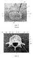
- FIG. 1is an image of a conventional straight insertion of a balloon tamp showing the offset relative to the midline of the vertebrae.
- FIG. 2is a photograph of a single entry into a vertebral model showing how the tunneling device curves to form a path crossing the midline.
- FIG. 3is a perspective view of the end portion of the tunneling device of the present invention.
- FIG. 3Ais a side view of the tunneling device of the present invention.
- FIG. 3Bis an enlarged view of the cut slots on the backside of the present invention.
- FIG. 4is an exploded view of the tunneling device of the present invention with an exemplary handle assembly.
- a balloon tamp 200is shown extending through a guide sleeve or cannula 100 .
- the balloon tamp 200is shown in an inflated condition.
- the balloon tamp 200when expanded, compresses the soft tissue or cancellous bone 4 such that a void cavity 5 is created.
- the straight line incision or opening 3is created for the guide sleeve 100 , it is known that the balloon tamp 200 when projecting inwardly on a straight line path is off center of the vertebrae.
- the cavity 5 createdis biased to the left or right side of the midline ML.
- various deviceshave been employed to try to provide a curved or angled path into the vertebral body 2 to form a cavity 5 in such a way to cross the rim of cortical bone so that it intersects the midline.
- hinged deviceshave been provided that upon insertion meet the cancellous tissue and collapse along hinges closing the device in such a fashion that it can create a curved path crossing the midline.
- steerable deviceshave been provided wherein some mechanical mechanism and or external forces are used to manipulate the device which is inserted straight and then bent or maneuvered over; this creates a windshield wiping effect.
- both of theseare inferior procedures for creating a good path tunnel for the balloon tamp 200 to follow.
- the tunneling devicesare primarily designed to create a path or passageway that the balloon tamp 200 can easily follow upon being inserted into the vertebral body 2 . If a swiping action or wide path is generated, it is uncertain where the balloon tamp 200 will end up as it is not effectively being guided by the passageway that was previously created. Accordingly, there is a need for an improved tunneling device in kyphoplasty procedures.
- the improved tunneling device 10 of the present inventionis illustrated.
- the guide sleeve 100passes through the pedicle, through the cortical bone 6 creating an opening 3 through which the tunneling device 10 can then extend.
- the guide sleeve 100is positioned off at an angle on the lower right hand side of FIG. 2 and the tunneling device 10 extends up into the cancellous bone 4 and as the tunneling device 10 leaves the guide sleeve 100 , the device 10 at the end 10 E initiates a predefined curvature having a curvilinear path 10 P as illustrated.
- a straight line 110 projecting from the guide sleeve 100which illustrates that the balloon tamp 200 as visualized by the circle would be centered on the midline, but if it followed the straight line 101 would have not intersected the midline ML or at least been offset.
- the center of the balloon tamp 200would have been greatly offset relative to the midline ML of the vertebral body 2 .
- the balloon tamp 200can be easily positioned right over the midline as shown by the line 110 extending tangent to the curved path and intersecting the center midline ML where the bone tamp 200 will be positioned.
- the balloon tamp 200can be positioned even further inwardly towards the center of the cancellous bone 4 such that the balloon tamp 200 can be maneuvered along a path centered along the guide path 10 P depending on the radius of curvature provided in the tunneling device 10 of the present invention.
- the tunneling device 10 of the present inventionachieves its predefined curvature having a curvilinear path 10 P without steering or any hingeable parts that collapse upon themselves due to any external resistance or forces.
- the tunneling device 10 of the present inventionis pre-set with a predefined curvature 10 P.
- This curvature 10 Pis set in the material in such a fashion that the device 10 has a curved path in its normal state, in other words once the tunneling device 10 leaves the cannula or guide sleeve 100 , the device 10 at the curved end 10 E will automatically return to its unrestrained curved shape.
- the device 10provides a curvilinear path 10 P as illustrated in FIG. 3 .
- An important feature of the device 10is unlike hinged devices wherein collapsible slots are provided, the slots 20 are provided on an opposite side relative to the radius of curvature R. Hinged devices have the slots on the same side as the radius of curvature R, this allows the hinges to close upon resistance of the soft cancellous tissue as the device is driving into the vertebrae.
- the present inventionhas the slots 20 on the opposite side as shown, these slots 20 actually open and are provided to allow the end portion 10 E of the tunneling device 10 to flex sufficiently that it can be straightened inside the guide sleeve 100 .
- the guide sleeve 100can be a cannula having a generally straight profile such that the tunneling device 10 contained therein will similarly initially be in a straight orientation prior to insertion.
- the device 10will initiate its natural curvature 10 P that has been predefined and pre-set. As shown in FIG.
- the device 10is made preferably of a rod of material, the rod can be solid or hollow, and preferably as illustrated it is a solid rod of material.
- the length L of the device 10 including the curved end portion 10 E extending from one end 21 to the opposite end 24is sufficient to allow the device 10 to extend outward of the cannula or guide sleeve 100 when in the fully inserted position.
- the end 24 of the devicecan be provided with a handle fixed by the flats 23 for an over-molded threaded portion 51 that is housed inside of the handle assembly of the device that prevent rotation in the handle such that the physician can easily push the device in.
- the handlewould indicate the orientation of the curve of the device 10 so that the physician can have an appreciation of the path that the predefined curvature 10 P will take when inserted into the guide sleeve 100 . This is important because as the device 10 is inserted, the physician wants the curvature to be such that the end portion 10 E of the device 10 as it curves crosses the midline of the vertebra 2 .
- an exemplary device 10 of the present inventionhas a diameter of 0.0905 inches 2.3 mm and a total straightened length of approximately 8.50 inches, 216 mm and a tangent angle at the maximum point of curvature of 0, 0 being greater than 0 degrees, preferably greater than 30 degrees, more preferably greater than 45 degrees; as shown 50 degrees relative to the straight line of the device 10 itself or the guide sleeve 100 when positioned in the vertebra 2 .
- the radius of curvature Ris shown as a single radius of curvature R, however, multiple radii of curvature R can be used if so desired and these multiple radii of curvature R can be pre-set into the device 10 similar to a single radius of curvature R.
- the rod materialthat has been rounded to facilitate insertion into the cancellous tissue material 4 .
- the slots 20 created in the back side or opposite side 13 relative to the side 11 of the radius of curvature Rare spaced generally uniformly along the curvature R. These slots extend inwardly at or slightly past the midline of the rod, however, leave a sufficient amount of material along the same surface 11 as the radius of curvature R such that the rod when in the straight position inside the guide sleeve 100 has sufficient strength so that it can resist forces that would tend to want to close or work in an opposite direction relative to the pre-set and predefined curvature 10 P to the radius of curvature R. This flexibility in the rod enables it to easily slide inside and be easily withdrawn from the cannula.
- the plurality of slots created along the surfaceare primarily for flexibility and during insertion it is further noted that the slots when straightened in the guide tube tend to close upon themselves. However, as soon as the rod is free, they return to their natural pre-set and predefined curvature 10 P tending to open the slots 20 . This is opposite the hinged devices which require the slots to close upon insertion.
- the tunnel device 10 with the predefined curvature at end portion 10 Ecan have a handle assembly 50 .
- the exemplary handle assembly 50has a threaded portion 51 secured in a fixed way on the device 10 rod at the distal end opposite the end portion 10 E; preferably, it is insert molded over the flats 23 so as to prevent rotation.
- a handle portion 52fits onto threaded portion 51 and is fixed so the surgeon can know the orientation of the curved end 10 E.
- the third handle piece 53possessing internal threads matching the external threads of the threaded portion 51 , threaded onto the threaded portion 51 and is fitted into the handle portion 52 round or circular opening 60 .
- the second and third portionsfit together on assembly.
- the third portion 53can be rotated clockwise to retract the threaded portion 51 further into the handle 52 and retracting shaft 10 and a portion of the curved end 10 E back into the guide sleeve 100 to facilitate extraction from the body.
- the slots 20are provided on that portion of the rod that would normally be under tensile stresses when bent in the direction as illustrated and the smooth portion of the rod adjacent the radius of curvature R would effectively be in compression.
- these materialsare generally set at this curvature and therefore the stresses of tensile and compression are not created by the curvature R, but rather there are no compressive or tensile stresses on the device as a result of the pre-set curvature because the device 10 has been made to take this precise shape.
- a shape memory tunnel device 10creates an optimal solution for creation of a curved path 10 P to cross the midline ML that can be used in this procedure.
- the path 10 P createdcan be a constant curvature R.
- the predefined curvature Ris set to optimize the ability of the surgeon to insert the tunneling device 10 into the cancellous material 4 and to be assured that the path 10 P created will follow that curvature such that the balloon tamp 200 when inserted will follow the path 10 P created and always be centered and crossing the midline ML of the vertebra 2 .
- the advantages of the present device 10are that the use of shape set materials means no additional forces such as the bone resistance or mechanisms such as separate tensile members to induce a curvature are needed.
- the curvatureis predefined and already in the device 10 as it is leaving the guide sleeve 100 , it returns to its pre-set curvature automatically in the absence of any external resistance or force.
- the bone cavitycould be filled with air or liquid and the device would simply return to its curved path 10 P without any influence or force required.
- the curved path 10 Pcan be formed as a constant profile and tangent to the working cannula or guide sleeve 100 it is introduced through.
- the designhas the advantage of being constructed from one piece of material and greatly reduces the possibility of device failure or breakage during the procedure.
- the shape set materialcan be nitinol, generally a nickel titanium material. However, other materials having shape set capability are known and similarly can be used. These materials can include other metal alloys, metals and polymers that have shape set properties.
- the shape set materialmay be induced by using a ferromagnetic shape set material that is responsive to magnetic fields. Or alternatively, can be a temperature set or current set curvature induced device. However, it is important to note that regardless of the type of device used, that it must have the predefined curvature already pre-set when it is positioned in the guide sleeve 100 .
- the present deviceallows the following method to be employed where one would access the vertebral body placing a cannula slightly into a vertebral body just anterior to the posterior wall and keeping the cannula in place creating the passageway with the trocar, removing the trocar and then to insert the tunneling device 10 distal end 10 E into the cannula 100 , this will straighten the device 10 so that it fits into the cannula 100 relatively easily with minor resistance.
- the surgeonwill align the curvature portion or path 10 P in the desired orientation so that the slots 20 are facing to the outside of the path 10 P to be created to ensure that the curvature follows a path that will cross the midline ML of the vertebra 2 .
- the surgeonwill then slowly advance the device 10 until the desired midline ML position is achieved. He can observe this using fluoroscope, x ray if so desired. Then without rotating, he will remove the device 10 to leave a midline crossing tunnel for kyphoplasty balloon tamp 200 to follow.
- the balloon tamp 200will then be inserted into the cannula or guide sleeve 100 and slowly introduced into the path created by the tunneling device 10 so that the balloon tamp 200 follows the curvature precisely crossing the midline ML of the vertebra 2 .
- the overall diameter (D) of the device 10can be greatly reduced from what is commonly used. While the device can be of the same size as currently used, it need not be, it can be minimized further if so desired. As a result, a smaller cannula can be used with this procedure.
- an 11 gauge rod of nitinol materialwas used.
- This 11 gauge rodhas a diameter of 2.3 mm as a result a cannula of only 2 to 3 mm can be used for this procedure.
- the limiting factor on using such a small diameter cannulais the ability to provide a balloon tamp 200 sufficiently small to be able to be inflated to the high pressures of 400 psi or more to create the balloon tamp cavity 5 .
- the ballooncan mounted on such a small diameter this would reduce the size from the prior art from approximately 11 to 12 mm by a factor of 5 if not 6 times smaller. This greatly reduces the size of the opening 3 which will further accelerate the healing of the patient. It is believed to be the most non-invasive procedure known for kyphoplasty.
- the device 10 of the present inventionwhile being described is a vast improvement over the current techniques of kyphoplasty, this device 10 can also be used in other procedures and any procedure where a tunneling device is needed to create a curved path 10 P.
- the tunnels in these casescan be used to clear a path into which medicants or tissue regenerating materials can be injected once a curvilinear path 10 P has been created into the disc area. In such a procedure, once the tunneling device 10 is removed a cannula made of a similar curvature would be provided.
- the cannulawill be a thin walled material of nitinol with a hollow center such that medicants can be injected through the cannula directly into the path inside the disc.
- a single entry guide sleeve 100through which a curved component with a pre-set curvature can be provided both for tunneling and for injecting materials into the final location where the surgeon needs to deliver either medicine or bone cement or any other fluid that can be injected into a particular location.
- the guide sleeve 100has been provided in a straight or generally straight configuration.
- the guide sleeve 100could alternatively have a slight curvature, however it is important to note that this is considered an alternative to straight, however in any event the optimal solution of the present invention is that the tunneling device 10 or cannula 100 depending on the procedure will have a pre-set and predefined curvature that is different and much smaller than any bowed curvature in the guide sleeve 100 and that upon leaving the entry opening 3 into the bone structure the tunneling device 10 or cannula will automatically go back to its pre-set curvature that is different from the path of the guide sleeve 100 .
- This change in pathis important in that it creates the ability to increase the curvature of the path created by the tunneling device 10 and/or the path created by the cannula or for later injection of materials.
- substantiallymeans approximately or very close to the, in the case of a straight line, a straight line.
Landscapes
- Health & Medical Sciences (AREA)
- Surgery (AREA)
- Life Sciences & Earth Sciences (AREA)
- Orthopedic Medicine & Surgery (AREA)
- Biomedical Technology (AREA)
- Public Health (AREA)
- Veterinary Medicine (AREA)
- Engineering & Computer Science (AREA)
- Nuclear Medicine, Radiotherapy & Molecular Imaging (AREA)
- Heart & Thoracic Surgery (AREA)
- Medical Informatics (AREA)
- Molecular Biology (AREA)
- Animal Behavior & Ethology (AREA)
- General Health & Medical Sciences (AREA)
- Dentistry (AREA)
- Oral & Maxillofacial Surgery (AREA)
- Neurology (AREA)
- Prostheses (AREA)
- Surgical Instruments (AREA)
Abstract
Description
Claims (13)
Priority Applications (1)
| Application Number | Priority Date | Filing Date | Title |
|---|---|---|---|
| US14/145,532US9351739B2 (en) | 2013-12-31 | 2013-12-31 | Tunneling device |
Applications Claiming Priority (1)
| Application Number | Priority Date | Filing Date | Title |
|---|---|---|---|
| US14/145,532US9351739B2 (en) | 2013-12-31 | 2013-12-31 | Tunneling device |
Publications (2)
| Publication Number | Publication Date |
|---|---|
| US20150182234A1 US20150182234A1 (en) | 2015-07-02 |
| US9351739B2true US9351739B2 (en) | 2016-05-31 |
Family
ID=53480496
Family Applications (1)
| Application Number | Title | Priority Date | Filing Date |
|---|---|---|---|
| US14/145,532Expired - Fee RelatedUS9351739B2 (en) | 2013-12-31 | 2013-12-31 | Tunneling device |
Country Status (1)
| Country | Link |
|---|---|
| US (1) | US9351739B2 (en) |
Cited By (17)
| Publication number | Priority date | Publication date | Assignee | Title |
|---|---|---|---|---|
| US9775627B2 (en) | 2012-11-05 | 2017-10-03 | Relievant Medsystems, Inc. | Systems and methods for creating curved paths through bone and modulating nerves within the bone |
| US10028753B2 (en) | 2008-09-26 | 2018-07-24 | Relievant Medsystems, Inc. | Spine treatment kits |
| US10111704B2 (en) | 2002-09-30 | 2018-10-30 | Relievant Medsystems, Inc. | Intraosseous nerve treatment |
| US10265099B2 (en) | 2008-09-26 | 2019-04-23 | Relievant Medsystems, Inc. | Systems for accessing nerves within bone |
| US10390877B2 (en) | 2011-12-30 | 2019-08-27 | Relievant Medsystems, Inc. | Systems and methods for treating back pain |
| US10456187B2 (en) | 2013-08-08 | 2019-10-29 | Relievant Medsystems, Inc. | Modulating nerves within bone using bone fasteners |
| US10463423B2 (en) | 2003-03-28 | 2019-11-05 | Relievant Medsystems, Inc. | Thermal denervation devices and methods |
| US10588691B2 (en) | 2012-09-12 | 2020-03-17 | Relievant Medsystems, Inc. | Radiofrequency ablation of tissue within a vertebral body |
| USRE48460E1 (en) | 2002-09-30 | 2021-03-09 | Relievant Medsystems, Inc. | Method of treating an intraosseous nerve |
| US11007010B2 (en) | 2019-09-12 | 2021-05-18 | Relevant Medsysterns, Inc. | Curved bone access systems |
| WO2021146015A1 (en)* | 2020-01-17 | 2021-07-22 | Wright Medical Technology, Inc. | Guidance tools, systems, and methods |
| US11298242B2 (en) | 2019-06-14 | 2022-04-12 | Medos International Sarl | Biomaterial delivery device, and related systems and methods |
| US12039731B2 (en) | 2020-12-22 | 2024-07-16 | Relievant Medsystems, Inc. | Prediction of candidates for spinal neuromodulation |
| US12082876B1 (en) | 2020-09-28 | 2024-09-10 | Relievant Medsystems, Inc. | Introducer drill |
| US12102348B2 (en) | 2016-09-07 | 2024-10-01 | Vertos Medical, Inc. | Percutaneous lateral recess resection methods and instruments |
| US12324572B2 (en) | 2022-06-16 | 2025-06-10 | Vertos Medical, Inc. | Integrated instrument assembly |
| US12433668B1 (en) | 2021-11-08 | 2025-10-07 | Relievant Medsystems, Inc. | Impedance stoppage mitigation during radiofrequency tissue ablation procedures |
Families Citing this family (11)
| Publication number | Priority date | Publication date | Assignee | Title |
|---|---|---|---|---|
| US8518087B2 (en) | 2011-03-10 | 2013-08-27 | Interventional Spine, Inc. | Method and apparatus for minimally invasive insertion of intervertebral implants |
| US8394129B2 (en) | 2011-03-10 | 2013-03-12 | Interventional Spine, Inc. | Method and apparatus for minimally invasive insertion of intervertebral implants |
| US9277928B2 (en) | 2013-03-11 | 2016-03-08 | Interventional Spine, Inc. | Method and apparatus for minimally invasive insertion of intervertebral implants |
| US9993353B2 (en) | 2013-03-14 | 2018-06-12 | DePuy Synthes Products, Inc. | Method and apparatus for minimally invasive insertion of intervertebral implants |
| FR3040869B1 (en)* | 2015-09-16 | 2017-10-20 | Vexim | CONTROLLED ROD CONTROL MECHANISM |
| JP7221194B2 (en)* | 2019-11-12 | 2023-02-13 | 美穂子 加藤 | tunneler for catheter implantation |
| CN111544163B (en)* | 2019-12-19 | 2025-01-28 | 广州爱锘德医疗器械有限公司 | Filler Syringes |
| KR102538277B1 (en)* | 2020-12-08 | 2023-05-30 | 가톨릭대학교 산학협력단 | endplate preparation tool for anterior cervical interbody fusion |
| US12329445B2 (en) | 2020-12-28 | 2025-06-17 | Boston Scientific Neuromodulation Corporation | RF ablation systems and methods using an integrated cannula and electrode |
| EP4572685A1 (en)* | 2022-10-04 | 2025-06-25 | Boston Scientific Neuromodulation Corporation | Tools for creating a vertebral tunnel for use in rf ablation and methods of making and using |
| US12433646B2 (en) | 2023-02-21 | 2025-10-07 | Boston Scientific Neuromodulation Corporation | Interspinous spacer with actuator locking arrangements and methods and systems |
Citations (22)
| Publication number | Priority date | Publication date | Assignee | Title |
|---|---|---|---|---|
| US5285795A (en) | 1991-09-12 | 1994-02-15 | Surgical Dynamics, Inc. | Percutaneous discectomy system having a bendable discectomy probe and a steerable cannula |
| US5322505A (en) | 1990-02-07 | 1994-06-21 | Smith & Nephew Dyonics, Inc. | Surgical instrument |
| US5695513A (en) | 1996-03-01 | 1997-12-09 | Metagen, Llc | Flexible cutting tool and methods for its use |
| US6719761B1 (en) | 1997-08-13 | 2004-04-13 | Kyphon Inc. | System and methods for injecting flowable materials into bones |
| US6875219B2 (en) | 2003-02-14 | 2005-04-05 | Yves P. Arramon | Bone access system |
| US20060247600A1 (en) | 2003-05-07 | 2006-11-02 | Yeung Jeffrey E | Device for treating back pain by re-establishing the exchage of nutrient & waste |
| US7318823B2 (en) | 1995-04-13 | 2008-01-15 | Arthrocare Corporation | Methods for repairing damaged intervertebral discs |
| US20080234827A1 (en) | 2005-08-16 | 2008-09-25 | Laurent Schaller | Devices for treating the spine |
| US7503920B2 (en) | 2004-08-11 | 2009-03-17 | Tzony Siegal | Spinal surgery system and method |
| US20090149878A1 (en) | 2007-12-07 | 2009-06-11 | Csaba Truckai | Bone treatment systems and methods |
| US20100298832A1 (en)* | 2009-05-20 | 2010-11-25 | Osseon Therapeutics, Inc. | Steerable curvable vertebroplasty drill |
| US7842041B2 (en) | 2007-11-16 | 2010-11-30 | Osseon Therapeutics, Inc. | Steerable vertebroplasty system |
| US20110015574A1 (en) | 2008-03-28 | 2011-01-20 | Jean-Charles Persat | Device for injecting a viscous fluid into the body |
| US7959634B2 (en) | 2004-03-29 | 2011-06-14 | Soteira Inc. | Orthopedic surgery access devices |
| US8048030B2 (en) | 1998-12-09 | 2011-11-01 | Cook Medical Technologies Llc | Hollow curved superelastic medical needle and method |
| US20110265789A1 (en) | 2010-04-28 | 2011-11-03 | Sabry Gabriel | Endo-tracheal intubation device with adjustably bendable stylet |
| US8096985B2 (en) | 2008-05-07 | 2012-01-17 | Guided Delivery Systems Inc. | Deflectable guide |
| US8128633B2 (en) | 2005-11-18 | 2012-03-06 | Carefusion 2200, Inc. | Device, system, and method for forming a cavity in and delivering a curable material into bone |
| US8157806B2 (en) | 2005-10-12 | 2012-04-17 | Synthes Usa, Llc | Apparatus and methods for vertebral augmentation |
| US8277506B2 (en) | 2008-06-24 | 2012-10-02 | Carefusion 2200, Inc. | Method and structure for stabilizing a vertebral body |
| US20130012951A1 (en) | 2011-07-08 | 2013-01-10 | Carefusion 207, Inc. | Systems and methods for treating a spine through a single vertebral body insertion point |
| US8414571B2 (en) | 2010-01-07 | 2013-04-09 | Relievant Medsystems, Inc. | Vertebral bone navigation systems |
- 2013
- 2013-12-31USUS14/145,532patent/US9351739B2/ennot_activeExpired - Fee Related
Patent Citations (23)
| Publication number | Priority date | Publication date | Assignee | Title |
|---|---|---|---|---|
| US5322505A (en) | 1990-02-07 | 1994-06-21 | Smith & Nephew Dyonics, Inc. | Surgical instrument |
| US5285795A (en) | 1991-09-12 | 1994-02-15 | Surgical Dynamics, Inc. | Percutaneous discectomy system having a bendable discectomy probe and a steerable cannula |
| US7318823B2 (en) | 1995-04-13 | 2008-01-15 | Arthrocare Corporation | Methods for repairing damaged intervertebral discs |
| US5695513A (en) | 1996-03-01 | 1997-12-09 | Metagen, Llc | Flexible cutting tool and methods for its use |
| US6719761B1 (en) | 1997-08-13 | 2004-04-13 | Kyphon Inc. | System and methods for injecting flowable materials into bones |
| US8048030B2 (en) | 1998-12-09 | 2011-11-01 | Cook Medical Technologies Llc | Hollow curved superelastic medical needle and method |
| US6875219B2 (en) | 2003-02-14 | 2005-04-05 | Yves P. Arramon | Bone access system |
| US20060247600A1 (en) | 2003-05-07 | 2006-11-02 | Yeung Jeffrey E | Device for treating back pain by re-establishing the exchage of nutrient & waste |
| US7959634B2 (en) | 2004-03-29 | 2011-06-14 | Soteira Inc. | Orthopedic surgery access devices |
| US7503920B2 (en) | 2004-08-11 | 2009-03-17 | Tzony Siegal | Spinal surgery system and method |
| US7918874B2 (en) | 2004-08-11 | 2011-04-05 | Nonlinear Technologies Ltd. | Devices for introduction into a body along a substantially straight guide to form a predefined curved configuration, and methods employing same |
| US20080234827A1 (en) | 2005-08-16 | 2008-09-25 | Laurent Schaller | Devices for treating the spine |
| US8157806B2 (en) | 2005-10-12 | 2012-04-17 | Synthes Usa, Llc | Apparatus and methods for vertebral augmentation |
| US8128633B2 (en) | 2005-11-18 | 2012-03-06 | Carefusion 2200, Inc. | Device, system, and method for forming a cavity in and delivering a curable material into bone |
| US7842041B2 (en) | 2007-11-16 | 2010-11-30 | Osseon Therapeutics, Inc. | Steerable vertebroplasty system |
| US20090149878A1 (en) | 2007-12-07 | 2009-06-11 | Csaba Truckai | Bone treatment systems and methods |
| US20110015574A1 (en) | 2008-03-28 | 2011-01-20 | Jean-Charles Persat | Device for injecting a viscous fluid into the body |
| US8096985B2 (en) | 2008-05-07 | 2012-01-17 | Guided Delivery Systems Inc. | Deflectable guide |
| US8277506B2 (en) | 2008-06-24 | 2012-10-02 | Carefusion 2200, Inc. | Method and structure for stabilizing a vertebral body |
| US20100298832A1 (en)* | 2009-05-20 | 2010-11-25 | Osseon Therapeutics, Inc. | Steerable curvable vertebroplasty drill |
| US8414571B2 (en) | 2010-01-07 | 2013-04-09 | Relievant Medsystems, Inc. | Vertebral bone navigation systems |
| US20110265789A1 (en) | 2010-04-28 | 2011-11-03 | Sabry Gabriel | Endo-tracheal intubation device with adjustably bendable stylet |
| US20130012951A1 (en) | 2011-07-08 | 2013-01-10 | Carefusion 207, Inc. | Systems and methods for treating a spine through a single vertebral body insertion point |
Cited By (44)
| Publication number | Priority date | Publication date | Assignee | Title |
|---|---|---|---|---|
| USRE48460E1 (en) | 2002-09-30 | 2021-03-09 | Relievant Medsystems, Inc. | Method of treating an intraosseous nerve |
| US10111704B2 (en) | 2002-09-30 | 2018-10-30 | Relievant Medsystems, Inc. | Intraosseous nerve treatment |
| US10478246B2 (en) | 2002-09-30 | 2019-11-19 | Relievant Medsystems, Inc. | Ablation of tissue within vertebral body involving internal cooling |
| US11596468B2 (en) | 2002-09-30 | 2023-03-07 | Relievant Medsystems, Inc. | Intraosseous nerve treatment |
| US10463423B2 (en) | 2003-03-28 | 2019-11-05 | Relievant Medsystems, Inc. | Thermal denervation devices and methods |
| US12329412B2 (en) | 2008-09-26 | 2025-06-17 | Relievant Medsystems, Inc. | Systems for accessing nerves within bone |
| US12161350B2 (en) | 2008-09-26 | 2024-12-10 | Relievant Medsystems, Inc. | Systems for treating nerves within bone using steam |
| US11471171B2 (en) | 2008-09-26 | 2022-10-18 | Relievant Medsystems, Inc. | Bipolar radiofrequency ablation systems for treatment within bone |
| US12303166B2 (en) | 2008-09-26 | 2025-05-20 | Relievant Medsystems, Inc. | Methods for accessing nerves within bone |
| US10028753B2 (en) | 2008-09-26 | 2018-07-24 | Relievant Medsystems, Inc. | Spine treatment kits |
| US10265099B2 (en) | 2008-09-26 | 2019-04-23 | Relievant Medsystems, Inc. | Systems for accessing nerves within bone |
| US10905440B2 (en) | 2008-09-26 | 2021-02-02 | Relievant Medsystems, Inc. | Nerve modulation systems |
| US10390877B2 (en) | 2011-12-30 | 2019-08-27 | Relievant Medsystems, Inc. | Systems and methods for treating back pain |
| US12059193B2 (en) | 2011-12-30 | 2024-08-13 | Relievant Medsystems, Inc. | Methods of denervating vertebral body using external energy source |
| US11471210B2 (en) | 2011-12-30 | 2022-10-18 | Relievant Medsystems, Inc. | Methods of denervating vertebral body using external energy source |
| US10588691B2 (en) | 2012-09-12 | 2020-03-17 | Relievant Medsystems, Inc. | Radiofrequency ablation of tissue within a vertebral body |
| US11701168B2 (en) | 2012-09-12 | 2023-07-18 | Relievant Medsystems, Inc. | Radiofrequency ablation of tissue within a vertebral body |
| US11737814B2 (en) | 2012-09-12 | 2023-08-29 | Relievant Medsystems, Inc. | Cryotherapy treatment for back pain |
| US11690667B2 (en) | 2012-09-12 | 2023-07-04 | Relievant Medsystems, Inc. | Radiofrequency ablation of tissue within a vertebral body |
| US11291502B2 (en) | 2012-11-05 | 2022-04-05 | Relievant Medsystems, Inc. | Methods of navigation and treatment within a vertebral body |
| US11234764B1 (en) | 2012-11-05 | 2022-02-01 | Relievant Medsystems, Inc. | Systems for navigation and treatment within a vertebral body |
| US11974759B2 (en) | 2012-11-05 | 2024-05-07 | Relievant Medsystems, Inc. | Methods of navigation and treatment within a vertebral body |
| US9775627B2 (en) | 2012-11-05 | 2017-10-03 | Relievant Medsystems, Inc. | Systems and methods for creating curved paths through bone and modulating nerves within the bone |
| US11160563B2 (en) | 2012-11-05 | 2021-11-02 | Relievant Medsystems, Inc. | Systems for navigation and treatment within a vertebral body |
| US10517611B2 (en) | 2012-11-05 | 2019-12-31 | Relievant Medsystems, Inc. | Systems for navigation and treatment within a vertebral body |
| US10357258B2 (en) | 2012-11-05 | 2019-07-23 | Relievant Medsystems, Inc. | Systems and methods for creating curved paths through bone |
| US12193719B2 (en) | 2013-08-08 | 2025-01-14 | Relievant Medsystems, Inc. | Modulating nerves within bone |
| US11065046B2 (en) | 2013-08-08 | 2021-07-20 | Relievant Medsystems, Inc. | Modulating nerves within bone |
| US10456187B2 (en) | 2013-08-08 | 2019-10-29 | Relievant Medsystems, Inc. | Modulating nerves within bone using bone fasteners |
| US12102348B2 (en) | 2016-09-07 | 2024-10-01 | Vertos Medical, Inc. | Percutaneous lateral recess resection methods and instruments |
| US11298242B2 (en) | 2019-06-14 | 2022-04-12 | Medos International Sarl | Biomaterial delivery device, and related systems and methods |
| US12433766B2 (en) | 2019-06-14 | 2025-10-07 | Medos International Sarl | Biomaterial delivery device, and related systems and methods |
| US11007010B2 (en) | 2019-09-12 | 2021-05-18 | Relevant Medsysterns, Inc. | Curved bone access systems |
| US11426199B2 (en) | 2019-09-12 | 2022-08-30 | Relievant Medsystems, Inc. | Methods of treating a vertebral body |
| US11207100B2 (en) | 2019-09-12 | 2021-12-28 | Relievant Medsystems, Inc. | Methods of detecting and treating back pain |
| US11202655B2 (en) | 2019-09-12 | 2021-12-21 | Relievant Medsystems, Inc. | Accessing and treating tissue within a vertebral body |
| US11123103B2 (en) | 2019-09-12 | 2021-09-21 | Relievant Medsystems, Inc. | Introducer systems for bone access |
| WO2021146015A1 (en)* | 2020-01-17 | 2021-07-22 | Wright Medical Technology, Inc. | Guidance tools, systems, and methods |
| US12396739B2 (en) | 2020-01-17 | 2025-08-26 | Wright Medical Technology, Inc. | Guidance tools, systems, and methods |
| US12082876B1 (en) | 2020-09-28 | 2024-09-10 | Relievant Medsystems, Inc. | Introducer drill |
| US12039731B2 (en) | 2020-12-22 | 2024-07-16 | Relievant Medsystems, Inc. | Prediction of candidates for spinal neuromodulation |
| US12433668B1 (en) | 2021-11-08 | 2025-10-07 | Relievant Medsystems, Inc. | Impedance stoppage mitigation during radiofrequency tissue ablation procedures |
| US12324572B2 (en) | 2022-06-16 | 2025-06-10 | Vertos Medical, Inc. | Integrated instrument assembly |
| US12342999B2 (en) | 2022-06-16 | 2025-07-01 | Vertos Medical, Inc. | Integrated instrument assembly |
Also Published As
| Publication number | Publication date |
|---|---|
| US20150182234A1 (en) | 2015-07-02 |
Similar Documents
| Publication | Publication Date | Title |
|---|---|---|
| US9351739B2 (en) | Tunneling device | |
| US10278755B2 (en) | Double threaded guidance or stiffening wire for multiple use vertebral augmentation (VA) balloon | |
| US9610083B2 (en) | Articulated cavity creator | |
| CA2766506C (en) | Surgical instruments for cutting cavities in intramedullary canals | |
| AU2009239515B2 (en) | Posterior spinal fastener | |
| US8556949B2 (en) | Hybrid bone fixation element and methods of using the same | |
| US9439693B2 (en) | Steerable needle assembly for use in vertebral body augmentation | |
| EP2730246B1 (en) | Apparatus for reinforcing bone and tools for mounting the same | |
| US20090198243A1 (en) | Device and method for stabilizing a damaged bone with a bone cement mixture | |
| JP5913331B2 (en) | Double-threaded guidewire or reinforcement wire for multi-use vertebral augmentation (VA) balloons | |
| US11389181B2 (en) | Steerable systems and methods for accessing bone | |
| BRPI0617335A2 (en) | apparatus for repositioning vertebrae | |
| US11399964B2 (en) | Operating instrument and method for spinal implant | |
| CN119630356A (en) | Treatment devices and screws | |
| JP2009119262A (en) | Removable closure unit for axial bone consolidation implant |
Legal Events
| Date | Code | Title | Description |
|---|---|---|---|
| AS | Assignment | Owner name:AMENDIA INC., GEORGIA Free format text:ASSIGNMENT OF ASSIGNORS INTEREST;ASSIGNORS:MAHONEY, JOHN;STAUBLY, CHRIS;DICKERSON, CHASE;REEL/FRAME:031876/0834 Effective date:20131231 | |
| AS | Assignment | Owner name:SILICON VALLEY BANK, AS ADMINISTRATIVE AGENT, GEOR Free format text:PATENT SECURITY AGREEMENT;ASSIGNORS:AMENDIA, INC.;OMNI ACQUISITION, INC.;REEL/FRAME:033696/0940 Effective date:20140905 | |
| ZAAA | Notice of allowance and fees due | Free format text:ORIGINAL CODE: NOA | |
| ZAAB | Notice of allowance mailed | Free format text:ORIGINAL CODE: MN/=. | |
| AS | Assignment | Owner name:OMNI ACQUISITION INC., GEORGIA Free format text:RELEASE BY SECURED PARTY;ASSIGNOR:SILICON VALLEY BANK, AS ADMINISTRATIVE AGENT;REEL/FRAME:038578/0828 Effective date:20160429 Owner name:AMENDIA, INC., GEORGIA Free format text:RELEASE BY SECURED PARTY;ASSIGNOR:SILICON VALLEY BANK, AS ADMINISTRATIVE AGENT;REEL/FRAME:038578/0828 Effective date:20160429 | |
| AS | Assignment | Owner name:ANTARES CAPITAL LP, AS AGENT, ILLINOIS Free format text:SECURITY INTEREST;ASSIGNOR:AMENDIA, INC.;REEL/FRAME:038587/0753 Effective date:20160429 | |
| AS | Assignment | Owner name:CORTLAND CAPITAL MARKET SERVICES LLC, AS AGENT, IL Free format text:SECURITY INTEREST;ASSIGNOR:AMENDIA, INC.;REEL/FRAME:038606/0520 Effective date:20160429 | |
| STCF | Information on status: patent grant | Free format text:PATENTED CASE | |
| FEPP | Fee payment procedure | Free format text:MAINTENANCE FEE REMINDER MAILED (ORIGINAL EVENT CODE: REM.); ENTITY STATUS OF PATENT OWNER: SMALL ENTITY | |
| AS | Assignment | Owner name:SPINAL ELEMENTS, INC., CALIFORNIA Free format text:MERGER AND CHANGE OF NAME;ASSIGNORS:SPINAL ELEMENTS, INC.;AMENDIA, INC.;REEL/FRAME:052024/0805 Effective date:20191231 | |
| FEPP | Fee payment procedure | Free format text:SURCHARGE FOR LATE PAYMENT, SMALL ENTITY (ORIGINAL EVENT CODE: M2554); ENTITY STATUS OF PATENT OWNER: SMALL ENTITY | |
| MAFP | Maintenance fee payment | Free format text:PAYMENT OF MAINTENANCE FEE, 4TH YR, SMALL ENTITY (ORIGINAL EVENT CODE: M2551); ENTITY STATUS OF PATENT OWNER: SMALL ENTITY Year of fee payment:4 | |
| FEPP | Fee payment procedure | Free format text:MAINTENANCE FEE REMINDER MAILED (ORIGINAL EVENT CODE: REM.); ENTITY STATUS OF PATENT OWNER: SMALL ENTITY | |
| AS | Assignment | Owner name:PERCEPTIVE CREDIT HOLDINGS IV, LP, NEW YORK Free format text:SECURITY INTEREST;ASSIGNORS:SPINAL ELEMENTS, INC.;CUSTOM SPINE ACQUISITION, INC.;OMNI ACQUISITION INC.;REEL/FRAME:067596/0295 Effective date:20240531 | |
| AS | Assignment | Owner name:SPINAL ELEMENTS, INC. (F.K.A. AMENDIA, INC.), CALIFORNIA Free format text:RELEASE BY SECURED PARTY;ASSIGNOR:CORTLAND CAPITAL MARKET SERVICES LLC, AS AGENT;REEL/FRAME:067605/0676 Effective date:20240531 Owner name:SPINAL ELEMENTS, INC. (F.K.A. AMENDIA, INC.), CALIFORNIA Free format text:RELEASE BY SECURED PARTY;ASSIGNOR:ANTARES CAPITAL LP, AS ADMINISTRATIVE AGENT;REEL/FRAME:067605/0599 Effective date:20240531 | |
| STCH | Information on status: patent discontinuation | Free format text:PATENT EXPIRED DUE TO NONPAYMENT OF MAINTENANCE FEES UNDER 37 CFR 1.362 | |
| FP | Lapsed due to failure to pay maintenance fee | Effective date:20240531 |