US9350163B2 - Inter-area oscillation detection - Google Patents
Inter-area oscillation detectionDownload PDFInfo
- Publication number
- US9350163B2 US9350163B2US13/277,071US201113277071AUS9350163B2US 9350163 B2US9350163 B2US 9350163B2US 201113277071 AUS201113277071 AUS 201113277071AUS 9350163 B2US9350163 B2US 9350163B2
- Authority
- US
- United States
- Prior art keywords
- frequency
- data
- oscillation
- processor
- power
- Prior art date
- Legal status (The legal status is an assumption and is not a legal conclusion. Google has not performed a legal analysis and makes no representation as to the accuracy of the status listed.)
- Active, expires
Links
- 230000010355oscillationEffects0.000titleclaimsabstractdescription79
- 238000001514detection methodMethods0.000titledescription4
- 238000005259measurementMethods0.000claimsabstractdescription17
- 230000005611electricityEffects0.000claimsabstractdescription15
- 238000001914filtrationMethods0.000claimsabstractdescription13
- 238000000034methodMethods0.000claimsabstractdescription12
- 238000010200validation analysisMethods0.000claimsdescription14
- 230000005540biological transmissionEffects0.000claimsdescription9
- 230000003534oscillatory effectEffects0.000claimsdescription2
- 230000004044responseEffects0.000claims2
- 238000010248power generationMethods0.000description14
- 238000004891communicationMethods0.000description9
- 238000003860storageMethods0.000description9
- 238000006243chemical reactionMethods0.000description4
- 238000010586diagramMethods0.000description4
- 230000008901benefitEffects0.000description3
- 230000006870functionEffects0.000description3
- 230000001360synchronised effectEffects0.000description3
- 238000004364calculation methodMethods0.000description2
- 238000007596consolidation processMethods0.000description2
- 238000013016dampingMethods0.000description2
- 238000013461designMethods0.000description2
- 238000011161developmentMethods0.000description2
- 238000004519manufacturing processMethods0.000description2
- VNWKTOKETHGBQD-UHFFFAOYSA-NmethaneChemical compoundCVNWKTOKETHGBQD-UHFFFAOYSA-N0.000description2
- 230000002085persistent effectEffects0.000description2
- 230000008569processEffects0.000description2
- 238000012545processingMethods0.000description2
- 241001061225ArcosSpecies0.000description1
- 230000003044adaptive effectEffects0.000description1
- 230000008859changeEffects0.000description1
- 239000003034coal gasSubstances0.000description1
- 230000003247decreasing effectEffects0.000description1
- 230000001934delayEffects0.000description1
- 238000009826distributionMethods0.000description1
- 230000004992fissionEffects0.000description1
- 239000002803fossil fuelSubstances0.000description1
- 238000012544monitoring processMethods0.000description1
- 239000003345natural gasSubstances0.000description1
- 230000008439repair processEffects0.000description1
- 238000005070samplingMethods0.000description1
- 238000000926separation methodMethods0.000description1
- 238000009987spinningMethods0.000description1
- 238000012546transferMethods0.000description1
Images


Classifications
- H—ELECTRICITY
- H02—GENERATION; CONVERSION OR DISTRIBUTION OF ELECTRIC POWER
- H02H—EMERGENCY PROTECTIVE CIRCUIT ARRANGEMENTS
- H02H7/00—Emergency protective circuit arrangements specially adapted for specific types of electric machines or apparatus or for sectionalised protection of cable or line systems, and effecting automatic switching in the event of an undesired change from normal working conditions
- H02H7/26—Sectionalised protection of cable or line systems, e.g. for disconnecting a section on which a short-circuit, earth fault, or arc discharge has occured
- H02H7/28—Sectionalised protection of cable or line systems, e.g. for disconnecting a section on which a short-circuit, earth fault, or arc discharge has occured for meshed systems
- H—ELECTRICITY
- H02—GENERATION; CONVERSION OR DISTRIBUTION OF ELECTRIC POWER
- H02H—EMERGENCY PROTECTIVE CIRCUIT ARRANGEMENTS
- H02H3/00—Emergency protective circuit arrangements for automatic disconnection directly responsive to an undesired change from normal electric working condition with or without subsequent reconnection ; integrated protection
- H02H3/02—Details
- H02H3/04—Details with warning or supervision in addition to disconnection, e.g. for indicating that protective apparatus has functioned
- H02H3/046—Signalling the blowing of a fuse
- H—ELECTRICITY
- H02—GENERATION; CONVERSION OR DISTRIBUTION OF ELECTRIC POWER
- H02H—EMERGENCY PROTECTIVE CIRCUIT ARRANGEMENTS
- H02H3/00—Emergency protective circuit arrangements for automatic disconnection directly responsive to an undesired change from normal electric working condition with or without subsequent reconnection ; integrated protection
- H02H3/02—Details
- H02H3/04—Details with warning or supervision in addition to disconnection, e.g. for indicating that protective apparatus has functioned
- H02H3/048—Checking overvoltage diverters
Definitions
- the subject matter disclosed hereinrelates to detection of inter-area low frequency oscillations in power lines.
- Inter-area low frequency oscillationshave become one of the major threats to reliable operations of large-scale power systems. Inter-area oscillations may occur when large synchronously interconnected power systems have rotor angle/frequency/power/voltage/current swings between the synchronous generators of a first subsystem (or of large power plant) and another subsystem (or other subsystems).
- Inter-area oscillationsnot only limit the amount of power transfer, but also threaten the system security, because they may lead to system instability, which may result in cascading outages in the system. Therefore, it is desirable to identify the characteristics of the inter-area oscillations, including oscillation frequency and damping ratio, so that proper actions can be taken based on the identification results to improve system damping and maintain system stability.
- a systemincludes a master relay configured to sample input signals related to measurements of characteristics of electricity passing through a power line, estimate an oscillation frequency of the sample input signals via a time-domain frequency estimation method, and estimate an oscillation magnitude of the sample input signals via an adjusted window Fourier transform calculation based on the estimated oscillation frequency.
- a non-transitory computer readable mediumincludes computer-readable instructions to receive input signals related to measurements of characteristics of electricity passing through a power line, validate the input signals, and estimate an oscillation frequency of the input signals via a time-domain frequency estimation method.
- a devicein a third embodiment, includes interface circuitry configured to receive first input signals related to measurements of characteristics of electricity passing through a first power line, filtering circuitry configured to filter the first input signals to generate filtered data, and a processor configured to estimate an oscillation frequency of the filtered data via a time-domain frequency estimation method.
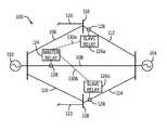
- FIG. 1is a block diagram of a power transmission system, in accordance with an embodiment
- FIG. 2is a is a block diagram of a master relay of the power transmission system of FIG. 1 , in accordance with an embodiment
- FIG. 3is flow diagram illustrating steps undertaken by the master relay of FIG. 2 to determine inter-area low frequency oscillations in power lines of the power transmission system of FIG. 1 .
- SSODsmall signal oscillation detector
- This SSODmay be implemented, for example, in one or more relays positioned in a power transmission system.
- the relaysutilizing the SSOD, may estimate an oscillation frequency and an oscillation magnitude on a given power line.
- Any SSODmay operate to provide alert to system operators or to cause a separation in the interconnected system (e.g., trip or interrupt the system) when a persistent or an unstable oscillation occurs.
- the SSODmay utilize real time measured analog quantities, for example frequency or real power on the power lines between different power systems to make determination if an alarm or trip signal should be issued.
- the measured datamay come from a local relay alone, or from one or more remote relays.
- FIG. 1represents a power transmission system 100 .
- the system 100may include a first power generation system 102 and a second power generation system 104 .
- Each of the power generation systems 102 and 104may represent one or more power plants powered by, for example, nuclear fission, burning of fossil fuels (such as coal or natural gas), wind, solar energy, or the like.
- the power generation systems 102 and 104may be separated by, for example, 50 miles, 100 miles, 200 miles, or more.
- each of the power generation systems 102 and 104may reside in differing regions such as different states, provinces, countries, or the like.
- power generation system 102may generate electricity that includes differing characteristics (voltage, current, etc.) than the electricity generated at power generation system 104 , based on, for example, the requirements and/or regulations of a particular region in which the power generation systems 102 and 104 are located.
- Power generation systems 102 and 104may each generate electricity to be transmitted across power lines 106 , 108 , 110 , 112 , and 114 (e.g., high voltage power lines). These power lines 106 , 108 , 110 , 112 , and 114 may transmit electricity at voltages, for example, of 110 kV or greater to substations 116 and 118 , which, for example, may include step-down transformers, to reduce the voltage of the electricity received. This stepped-down voltage may then be distributed to customers, for example, along distribution lines 120 and 122 .
- power lines 106 , 108 , 110 , 112 , and 114may transmit electricity at voltages, for example, of 110 kV or greater to substations 116 and 118 , which, for example, may include step-down transformers, to reduce the voltage of the electricity received. This stepped-down voltage may then be distributed to customers, for example, along distribution lines 120 and 122 .
- the power transmission system 100may include relays, such as master relay 124 and slave relays 126 a and 126 b .
- Each of the master relay 124 and the slave relays 126 a and 126 bmay operate to monitor a particular power line, power line 108 , 112 , and 114 , respectively, to detect inter-area low frequency oscillations caused by, for example, power generation systems 102 and 104 transmitting power in a non-synchronous manner. This monitoring may occur via interface circuitry 128 that may be coupled (externally or internally) to each of the master relay 124 and the slave relays 126 a and 126 b .
- the interface circuitry 128may detect disturbances in the electricity passing through the power lines, for example, power lines 108 , 112 , and 114 , that may then be utilized by the master relay 124 and the slave relays 126 a and 126 b to detect inter-area low frequency oscillations.
- a single master relay 124may receive measurements relating to inter-area low frequency oscillations from a single one of the slave relays 126 a and 126 b .
- the master relay 124may receive measurements relating to inter-area low frequency oscillations from more than one of the slave relays 126 a and 126 b , for example, two, three, four, five, or more slave relays.
- each of the master relay 124 and the slave relays 126 a and 126 bmay independently determine if inter-area low frequency oscillations are occurring on its monitored power line (e.g., power lines 108 , 112 , and 114 , respectively) independently from any other relays.
- communication channels 130 a and 130 bmay be an International Electrotechnical Commission's (IEC) 61850 standard communication link.
- IECInternational Electrotechnical Commission's
- the communication channels 130 a and 130 bmay utilize a known wired communication channel, such as an Ethernet connection, or may utilize a known wireless communication channel, such as a wide area network or a local area network, to transmit information between, for example, slave relay 126 a and master relay 124 .
- a known wired communication channelsuch as an Ethernet connection
- a known wireless communication channelsuch as a wide area network or a local area network
- FIG. 2illustrates an embodiment of the master relay 124 .
- each of the slave relays 126 a and 126 bmay include substantially all of the same components as will be discussed below with respect to master relay 124 .
- Master relay 124may include one or more processors 132 and/or other data processing circuitry that may be operably coupled to a memory 134 and storage 136 to execute instructions for carrying out the presently disclosed techniques. These instructions may be encoded in programs that may be executed by the one or more processors 132 .
- the instructionsmay be stored in any suitable article of manufacturer that includes at least one tangible non-transitory, computer-readable medium that at least collectively stores these instructions or routines, such as the memory 134 or the storage 136 .
- the processor(s) 132may provide the processing capability to execute an operating system, programs, and/or any other functions of the master relay 124 .
- the processor(s) 132may operate to run a small signal oscillation detector (SSOD).
- the SSODmay be an algorithm, stored on a tangible machine readable medium such as memory 134 and or storage 136 , that may include steps or functions performed by the processor(s) 132 . These steps or functions may allow for estimation of an oscillation frequency and an oscillation magnitude on one or more given power lines (e.g., power line 108 ) to aid in preventing inter-area low frequency oscillations.
- the processor(s) 132may include one or more microprocessors, such as one or more “general-purpose” microprocessors, one or more special-purpose microprocessors and/or ASICS, or some combination thereof. Furthermore, as noted above, instructions or data to be processed by the processor(s) 132 may be stored in a computer-readable medium, such as a memory 134 .
- Memory 134may include volatile memory, such as random access memory (RAM), and/or as a non-volatile memory, such as read-only memory (ROM).
- Memory 134may, for example, store firmware for the master relay 124 (such as a basic input/output instructions or operating system instructions), as well as various programs, applications, or routines executable by the processor(s) 132 in the master relay 124 (e.g., the SSOD).
- firmware for the master relay 124such as a basic input/output instructions or operating system instructions
- various programs, applications, or routines executable by the processor(s) 132 in the master relay 124e.g., the SSOD.
- master relay 124may also include computer-readable media, such as storage 136 .
- Storage 136may include non-volatile storage for persistent storage of data and/or instructions.
- the storage 136may include flash memory, a hard drive, solid-state storage media, or any other known non-volatile media.
- the master relay 124may also include input/output (I/O) ports 138 for connection to external devices (e.g., a portable computer, etc.) so that on site diagnostics and/or repairs of the master relay 124 may be accomplished.
- I/Oinput/output
- the master relay 124may include a network interface 140 .
- the network interface 140may provide communication via a wireless network, such as a local area network (LAN) (e.g., Wi-Fi), a wide area network (WAN) (e.g., 3G or 4G), or a physical connection, such as an Ethernet connection, an IEC 61850 standard communication link, and/or the like.
- LANlocal area network
- WANwide area network
- 4G3G or 4G
- the network interface 140may receive signals from one or more of the slave relays 126 a and 126 b relating to measurements for determination of inter-area low frequency oscillations on the power lines (e.g., power lines 112 and 114 ) that the slave relays 126 a and 126 b monitor.
- the master relay 124may include conversion circuitry 142 .
- This conversion circuitry 142may be utilized to receive measurements relating to oscillations in the power passing through a power line, for example, power line 108 .
- conversion circuitry 142may include the interface circuitry 128 from FIG. 1 or the interface circuitry 128 may be coupled thereto.
- the conversion circuitry 142may include one or more filtering circuits 144 and an analog to digital (A/D) converter circuit 146 .
- the one or more filtering circuits 144may filter signals received from the interface circuitry 128 , for example, to operate as an anti-aliasing filter, a band pass filter, or the like.
- the A/D converter circuit 146may operate on the filtered signals, for example, to produce digital signals that may be utilized by the processor(s) 132 in conjunction with the SSOD program to allow for estimation of an oscillation frequency and/or an oscillation magnitude on one or more given power lines.
- FIG. 3illustrates steps that are undertaken to estimate inter-area low frequency oscillations utilizing, for example, the SSOD program as executed in the master relay 124 of FIG. 2 .
- FIG. 3is a flow diagram 148 illustrating the steps undertaken to detect and alert of the presence of inter-area low frequency oscillations in real time.
- step 150data may be received, for example, at the master relay 124 from the slave relays 126 a and 126 b . As previously noted, this data may be received through the network interface 140 of the master relay 124 from communication channels 130 a and 130 b . Additionally or alternatively, the data may be received in step 150 from the interface circuitry 128 of the master relay 124 .
- Step 152the data received in step 150 may be aligned and consolidated.
- Step 152may include, for example, alignment and configuration of real power data and/or frequency data that are to be used as input signals (data values) to the SSOD program.
- other signalsmay be used, such as voltage, current, reactive power, angle differences, etc.
- utilization of frequency signalsmay allow for measurement to be undertaken locally (e.g., at the master relay 124 ) without requiring data from the slave relays 126 a and 126 b . This may lead to computational efficiencies, as less overall data is utilized by the SSOD.
- data from the slave relays 126 a and 126 bmay be utilized in conjunction with data from the master relay.
- datamay be captured at a fixed sample rate, for example, every 10 ms, 20 ms, 50 ms, 100 ms, or at another rate.
- Data synchronizationmay be performed on the sampled data via, for example, the processor(s) 132 using linear interpolation based on a timestamp, with the synchronized data being subsequently stored in an alignment buffer, for example, in memory 134 .
- data that is received outside of a particular timeslotfor example, past 1 ⁇ 3 of the interval selected (e.g., 33 ms for a 100 ms interval) is discarded as invalid as part of the synchronization process.
- if two consecutive measurements are invalide.g., if the data is received outside of a particular timeslot
- data stored to that pointis reset and the SSOD element is blocked until a set of consecutive valid measurements (e.g. data) are received (e.g., valid data received for 5 seconds, 10 seconds, 20 seconds, etc.).
- a set of consecutive valid measurementse.g. data
- the datais aligned (via the time it is received) and consolidated (by grouping any received data from a given time into a particular set) during step 152 .
- the alignment and consolidation step 152may be performed by the SSOD program being run on the processor(s) 132 .
- the datamay be filtered and validated in step 154 .
- filteringmay be accomplished by the filtering circuits 144 .
- This filtering in step 154may include removing a direct current (DC) component from the data signals (as the subsequent oscillation detection and validation checks may be based on alternating current (AC) components of the signals).
- the filtering in step 154may also include passing the data through a low pass filter in the filtering circuits 144 to eliminate high frequency noise elements in the data.
- the filtered datamay also be validated in step 154 .
- the in-band frequencye.g., the possible inter-area oscillation frequency range
- a time domain validation checkmay be utilized that determines whether the low pass filtered data signals lie within the correct in-band frequencies. Additional validations such as dead band checking, to determine whether consecutive positive AC samples exceed an upper dead band threshold and consecutive negative AC samples exceed a lower dead band threshold may be performed.
- the dead band thresholdsmay include tolerance levels for the steady state operation of the sample signals (e.g., whether the samples are within a preset tolerance). This dead band checking may prevent the SSOD algorithm from proceeding when low magnitude noises (oscillations in the sample data) are present.
- a past period validationmay be undertaken by the SSOD program in step 154 .
- This past period validationmay include determining whether samples for a previous period have been oscillatory in nature, e.g., that the input signal in the past period has included positive samples followed by consecutive negative samples followed by consecutive positive samples. Also verified is that the number of consecutive positive samples and the number of consecutive negative samples are within the expected limit. If each of these validations are confirmed by the SSOD, step 156 is undertaken.
- a frequency estimation for a inter-area low frequency oscillationis undertaken.
- Nminteger( fs/f avg( n ))
- uis the input signal after the process of alignment, consolidation, filtering and validation
- fis the estimated raw frequency of the oscillation
- favgis the N point average of f
- nis the sample index
- Tsis the sampling interval
- Nis the total number of samples in one oscillation period
- kis a number of sample delays.
- both N and kmay vary in run time such that, for example, in each loop of running the SSOD program, if N ⁇ Nm, the N is increased by 1 whereas if N>Nm, N is decreased by 1, and k is set to the maximum value between N/12 and 3.
- Ni.e. the total number of samples in one oscillation period
- the oscillation magnitudemay then be calculated in step 158 by using an adaptive window length full cycle Fourier transform, i.e. a Fourier transform window length will follow the change of number N.
- the window lengthe.g., amount of data to be operated on
- the Fourier transformmay be adjusted based on the estimated oscillation frequency that has been determined.
- the estimated oscillation magnitudemay be realized by the SSOD program. Moreover, based on the estimated oscillation magnitude determined in step 158 , an alarm and/or trip decision may be made by the SSOD program in step 160 .
- the SSOD programmay determine if the estimated oscillation magnitude determined in step 158 , for example, exceeds a predetermined alarm threshold value. If the predetermined alarm threshold is exceeded, the SSOD program may trigger an alarm signal to be sent in step 160 , for example, to one or both of the power generation systems 102 and 104 . In one embodiment, this alarm may be transmitted via the network interface 140 of the master relay 124 . This alarm may indicate that inter-area low frequency oscillations have been detected and may signal the power generation systems 102 and 104 that problems due to inter-area low frequency oscillations are impending.
- the SSOD programmay determine if the estimated oscillation magnitude determined in step 158 , for example, exceeds a predetermined trip threshold value.
- This trip threshold valuemay be the same value as or may differ from the value of the predetermined alarm threshold. If the predetermined trip threshold is exceeded, the SSOD program may trigger a trip signal to be sent in step 160 , for example, to one or both of the power generation systems 102 and 104 . In one embodiment, this trip signal may be transmitted via the network interface 140 of the master relay 124 .
- This trip signalmay indicate that inter-area low frequency oscillations have been detected and may signal the power generation systems 102 and 104 that problems are impending and that at least one of the power lines (e.g., power line 108 ) should be tripped (e.g., reset).
- the master relay 124may itself trip the power line (e.g., power line 108 ) via, for example, the interface circuitry 128 .
Landscapes
- Remote Monitoring And Control Of Power-Distribution Networks (AREA)
Abstract
Description
f(n)=1/(2πkTs)*arcos {0.5*[u(n−2k)*u(n−k)−u(n)*u(n−3k)]/[u(n−k)*u(n−k)−u(n)*u(n−2k)]}
favg(n)=(1/N)*(f(n)+f(n−1)+ . . . +f(n−N+1))
Nm=integer(fs/favg(n))
Cp=cos(2πp/N)
Sp=−sin(2πp/N)
UC(n)=(2/N)*SUM(u(n−p+N+1)*Cp)
US(n)=(2/N)*SUM(u(n−p+N+1)*Sp)
Umag(n)=sqrt(UC(n)^2+US(n)^2)
Claims (19)
Priority Applications (1)
| Application Number | Priority Date | Filing Date | Title |
|---|---|---|---|
| US13/277,071US9350163B2 (en) | 2011-10-19 | 2011-10-19 | Inter-area oscillation detection |
Applications Claiming Priority (1)
| Application Number | Priority Date | Filing Date | Title |
|---|---|---|---|
| US13/277,071US9350163B2 (en) | 2011-10-19 | 2011-10-19 | Inter-area oscillation detection |
Publications (2)
| Publication Number | Publication Date |
|---|---|
| US20130100564A1 US20130100564A1 (en) | 2013-04-25 |
| US9350163B2true US9350163B2 (en) | 2016-05-24 |
Family
ID=48135788
Family Applications (1)
| Application Number | Title | Priority Date | Filing Date |
|---|---|---|---|
| US13/277,071Active2033-05-03US9350163B2 (en) | 2011-10-19 | 2011-10-19 | Inter-area oscillation detection |
Country Status (1)
| Country | Link |
|---|---|
| US (1) | US9350163B2 (en) |
Families Citing this family (28)
| Publication number | Priority date | Publication date | Assignee | Title |
|---|---|---|---|---|
| US9075545B2 (en)* | 2012-08-01 | 2015-07-07 | Hewlett-Packard Development Company, L.P. | Synchronizing sensor data using timestamps and signal interpolation |
| US20150035542A1 (en)* | 2013-08-02 | 2015-02-05 | Battelle Memorial Institute | Method of detecting oscillations using coherence |
| US8990036B1 (en)* | 2013-09-16 | 2015-03-24 | Schweitzer Engineering Laboratories, Inc. | Power line parameter adjustment and fault location using traveling waves |
| US9588168B2 (en) | 2013-09-16 | 2017-03-07 | Schweitzer Engineering Laboratories, Inc. | Fault location using traveling waves |
| US9594112B2 (en) | 2014-09-16 | 2017-03-14 | Schweitzer Engineering Laboratories, Inc. | Fault detection in electric power delivery systems using underreach, directional, and traveling wave elements |
| US10291025B2 (en) | 2015-04-22 | 2019-05-14 | General Electric Company | Systems and methods for improved stability of power systems |
| US10090664B2 (en) | 2015-09-18 | 2018-10-02 | Schweitzer Engineering Laboratories, Inc. | Time-domain directional line protection of electric power delivery systems |
| US10310004B2 (en) | 2015-09-18 | 2019-06-04 | Schweitzer Engineering Laboratories, Inc. | Time-domain differential line protection of electric power delivery systems |
| EP3363095A4 (en) | 2015-10-12 | 2019-08-14 | Schweitzer Engineering Laboratories, Inc. | Traveling wave directional element |
| EP3362805A4 (en) | 2015-10-13 | 2019-06-19 | Schweitzer Engineering Laboratories, Inc. | Electric power system monitoring using high-frequency signals |
| US10564246B2 (en) | 2015-10-13 | 2020-02-18 | Schweitzer Engineering Laboratories, Inc. | Testing system for traveling wave fault detectors |
| US10564247B2 (en) | 2015-10-13 | 2020-02-18 | Schweitzer Engineering Laboratories, Inc. | Testing system for traveling wave fault detectors |
| EP3362807A4 (en) | 2015-10-14 | 2019-06-26 | Schweitzer Engineering Laboratories, Inc. | High-frequency electric power system signal processing system |
| EP3469385A1 (en) | 2016-06-13 | 2019-04-17 | Schweitzer Engineering Laboratories, Inc. | Overcurrent element in time domain |
| WO2017218558A1 (en) | 2016-06-14 | 2017-12-21 | Schweitzer Engineering Laboratories, Inc. | Phase selection for traveling wave fault detection systems |
| US10236675B2 (en) | 2016-07-26 | 2019-03-19 | Schweitzer Engineering Laboratories, Inc. | Fault detection and protection during steady state using traveling waves |
| US10585133B2 (en) | 2016-11-11 | 2020-03-10 | Schweitzer Engineering Laboratories, Inc. | Electric power fault protection device using single-ended traveling wave fault location estimation |
| US10295585B2 (en) | 2016-11-11 | 2019-05-21 | Schweitzer Engineering Laboratories, Inc. | Traveling wave based single end fault location |
| US10983150B2 (en)* | 2017-08-28 | 2021-04-20 | General Electric Technology Gmbh | Systems and methods for detecting and evaluating oscillations in an electrical power grid |
| US11280834B2 (en) | 2018-08-30 | 2022-03-22 | Schweitzer Engineering Laboratories, Inc. | Detection of low-energy events in an electric power system |
| US10677834B2 (en) | 2018-09-14 | 2020-06-09 | Schweitzer Engineering Laboratories, Inc. | Distance protection of electric power delivery systems using time domain and frequency domain |
| US10641815B2 (en) | 2018-09-27 | 2020-05-05 | Schweitzer Engineering Laboratories, Inc. | Secure distance protection of electric power delivery systems under transient conditions |
| US11067617B2 (en) | 2018-10-08 | 2021-07-20 | Schweitzer Engineering Laboratories, Inc. | Single-end traveling wave fault location using line-mounted device |
| US11592498B2 (en) | 2020-10-02 | 2023-02-28 | Schweitzer Engineering Laboratories, Inc. | Multi-phase fault identification in capacitor banks |
| US11735907B2 (en) | 2021-02-03 | 2023-08-22 | Schweitzer Engineering Laboratories, Inc. | Traveling wave overcurrent protection for electric power delivery systems |
| US11808824B2 (en) | 2021-03-17 | 2023-11-07 | Schweitzer Engineering Laboratories, Inc. | Systems and methods to identify open phases of a capacitor bank |
| US12313701B2 (en) | 2021-03-17 | 2025-05-27 | Schweitzer Engineering Laboratories, Inc. | Capacitor bank fault detection and identification |
| US12130322B2 (en) | 2022-12-02 | 2024-10-29 | Schweitzer Engineering Laboratories, Inc. | Traveling wave analysis and fault locating for electric power systems |
Citations (11)
| Publication number | Priority date | Publication date | Assignee | Title |
|---|---|---|---|---|
| US4788653A (en)* | 1986-12-23 | 1988-11-29 | General Electric Company | Digital filter for power system stabilizer |
| US4855861A (en)* | 1987-11-12 | 1989-08-08 | Asea Brown Boveri Ab | Longitudinal differential protection |
| US6476521B1 (en)* | 2000-05-31 | 2002-11-05 | Abb Ab | Power oscillation protection |
| US6662124B2 (en)* | 2002-04-17 | 2003-12-09 | Schweitzer Engineering Laboratories, Inc. | Protective relay with synchronized phasor measurement capability for use in electric power systems |
| US20050187726A1 (en) | 2003-06-21 | 2005-08-25 | Abb Research Ltd. | Detecting electromechanical oscillations in power systems |
| US20050231871A1 (en)* | 2004-04-05 | 2005-10-20 | Karimi Ghartemani Masoud M K | Three-phase power signal processor |
| US20090088990A1 (en)* | 2007-09-30 | 2009-04-02 | Schweitzer Iii Edmund O | Synchronized phasor processor for a power system |
| US20090099798A1 (en) | 2007-10-09 | 2009-04-16 | Yanfeng Gong | Real-Time Power System Oscillation Detection Using Modal Analysis |
| US20130096854A1 (en)* | 2011-10-12 | 2013-04-18 | Schweitzer Engineering Laboratories, Inc. | Fault Location Using Traveling Waves |
| US8494795B2 (en)* | 2008-05-05 | 2013-07-23 | Schweitzer Engineering Laboratories Inc | Apparatus and method for estimating synchronized phasors at predetermined times referenced to a common time standard in an electrical system |
| US20140361537A1 (en)* | 2010-09-28 | 2014-12-11 | Björn Andresen | Power oscillation damping by a converter-based power generation device |
- 2011
- 2011-10-19USUS13/277,071patent/US9350163B2/enactiveActive
Patent Citations (12)
| Publication number | Priority date | Publication date | Assignee | Title |
|---|---|---|---|---|
| US4788653A (en)* | 1986-12-23 | 1988-11-29 | General Electric Company | Digital filter for power system stabilizer |
| US4855861A (en)* | 1987-11-12 | 1989-08-08 | Asea Brown Boveri Ab | Longitudinal differential protection |
| US6476521B1 (en)* | 2000-05-31 | 2002-11-05 | Abb Ab | Power oscillation protection |
| US6662124B2 (en)* | 2002-04-17 | 2003-12-09 | Schweitzer Engineering Laboratories, Inc. | Protective relay with synchronized phasor measurement capability for use in electric power systems |
| US20050187726A1 (en) | 2003-06-21 | 2005-08-25 | Abb Research Ltd. | Detecting electromechanical oscillations in power systems |
| US7149637B2 (en) | 2003-06-21 | 2006-12-12 | Abb Research Ltd | Detecting electromechanical oscillations in power systems |
| US20050231871A1 (en)* | 2004-04-05 | 2005-10-20 | Karimi Ghartemani Masoud M K | Three-phase power signal processor |
| US20090088990A1 (en)* | 2007-09-30 | 2009-04-02 | Schweitzer Iii Edmund O | Synchronized phasor processor for a power system |
| US20090099798A1 (en) | 2007-10-09 | 2009-04-16 | Yanfeng Gong | Real-Time Power System Oscillation Detection Using Modal Analysis |
| US8494795B2 (en)* | 2008-05-05 | 2013-07-23 | Schweitzer Engineering Laboratories Inc | Apparatus and method for estimating synchronized phasors at predetermined times referenced to a common time standard in an electrical system |
| US20140361537A1 (en)* | 2010-09-28 | 2014-12-11 | Björn Andresen | Power oscillation damping by a converter-based power generation device |
| US20130096854A1 (en)* | 2011-10-12 | 2013-04-18 | Schweitzer Engineering Laboratories, Inc. | Fault Location Using Traveling Waves |
Non-Patent Citations (5)
| Title |
|---|
| A. R. Messina, Vijay Vittal, Nonlinear, Non-Stationary Analysis of Interarea Oscillations via Hilbert Spectral Analysis, IEEE Transactions on Power Systems, vol. 21, No. 3, August 2006, 1234-1241.* |
| B. B Kasztcnny, w. Premerlanit, M. Adamiak, Synchrophasor Algorithm Allowing Seamless Integration with Today's Relays, General Electric Company, Mar. 17-20, 2008, 724-729.* |
| Casper Labuschagnc and Nonnann Fischer, Transformer Fault Analysis Using Event Osci Ilography, Schweitzer Engineering Laboratories, Inc., IEEE, 2007, 467-482.* |
| O. Faucon' and Laurent Dousser, Coordinated Defense Plan Protects Against Transient Instabilities, IEEE, 1997, 22-26.* |
| Zhang et al., "Inter-Area Oscillation Detection by Modern Digital Relay," 37th Western Protective Relay Conference, Oct. 19-21, 2010, pp. 1-22, Spokane, WA. |
Also Published As
| Publication number | Publication date |
|---|---|
| US20130100564A1 (en) | 2013-04-25 |
Similar Documents
| Publication | Publication Date | Title |
|---|---|---|
| US9350163B2 (en) | Inter-area oscillation detection | |
| Liu et al. | Dynamic state estimation for power system control and protection | |
| CN103688434B (en) | Fault identification and location in a power supply line which is fed from one side | |
| CN103529321B (en) | CT saturation detection method | |
| Alinezhad et al. | Out-of-step protection based on equal area criterion | |
| CN105119286B (en) | Subsynchronous oscillation source location method and apparatus | |
| CN104242267B (en) | A kind of wind-power electricity generation sends out transmission line distance protecting method | |
| US11162994B2 (en) | Fault current calculation during transformer saturation using the waveform unsaturated region | |
| KR101778772B1 (en) | The System and Method of Detecting Events by Checking Frequency in Microgrid | |
| CN103490511A (en) | Power distribution network communication terminal detection system and method | |
| CN105138843A (en) | Electric system sampling flying spot detection and repair method thereof | |
| CN110031703A (en) | A kind of the unusual service condition method of discrimination and system of super extra-high voltage transformer | |
| CN116125174A (en) | A High Impedance Fault Detection Method Based on Pearson Correlation Coefficient Algorithm | |
| JP2023502659A (en) | Machine Learning Based Method and Apparatus for Transmission Line Disturbance Classification | |
| KR101323999B1 (en) | Apparatus and method for correcting of acquired data | |
| CN106154025B (en) | A Method of Merging Units to Eliminate Single-point Abnormal Data | |
| CN118983947A (en) | A substation monitoring system with feedback response terminal | |
| US10983150B2 (en) | Systems and methods for detecting and evaluating oscillations in an electrical power grid | |
| CN105067960B (en) | A kind of Distribution Fault Location System and its method based on big data | |
| US20230069041A1 (en) | Detection of incipient failures in instrument transformers | |
| Tholomier et al. | Phasor measurement units: Functionality and applications | |
| Zweigle et al. | Adding shaft angle measurement to generator protection and monitoring | |
| CN101242093A (en) | Integrated relay protection system based on multi-channel transient polarity direction comparison algorithm | |
| CN103701154B (en) | The machine unit automatic generation control target instruction target word receiving system of generating electricity by way of merging two or more grid systems | |
| CN109387724A (en) | Based on the lateral modified synchronous capacitor method for diagnosing faults of vertical analysis |
Legal Events
| Date | Code | Title | Description |
|---|---|---|---|
| AS | Assignment | Owner name:GENERAL ELECTRIC COMPANY, NEW YORK Free format text:ASSIGNMENT OF ASSIGNORS INTEREST;ASSIGNORS:ZHANG, ZHIYING;VOLOH, ILIA;CARDENAS MEDINA, JORGE EDUARDO;SIGNING DATES FROM 20111222 TO 20111223;REEL/FRAME:027487/0306 | |
| STCF | Information on status: patent grant | Free format text:PATENTED CASE | |
| FEPP | Fee payment procedure | Free format text:MAINTENANCE FEE REMINDER MAILED (ORIGINAL EVENT CODE: REM.); ENTITY STATUS OF PATENT OWNER: LARGE ENTITY | |
| FEPP | Fee payment procedure | Free format text:SURCHARGE FOR LATE PAYMENT, LARGE ENTITY (ORIGINAL EVENT CODE: M1554); ENTITY STATUS OF PATENT OWNER: LARGE ENTITY | |
| MAFP | Maintenance fee payment | Free format text:PAYMENT OF MAINTENANCE FEE, 4TH YEAR, LARGE ENTITY (ORIGINAL EVENT CODE: M1551); ENTITY STATUS OF PATENT OWNER: LARGE ENTITY Year of fee payment:4 | |
| MAFP | Maintenance fee payment | Free format text:PAYMENT OF MAINTENANCE FEE, 8TH YEAR, LARGE ENTITY (ORIGINAL EVENT CODE: M1552); ENTITY STATUS OF PATENT OWNER: LARGE ENTITY Year of fee payment:8 | |
| AS | Assignment | Owner name:GE INFRASTRUCTURE TECHNOLOGY LLC, SOUTH CAROLINA Free format text:ASSIGNMENT OF ASSIGNORS INTEREST;ASSIGNOR:GENERAL ELECTRIC COMPANY;REEL/FRAME:065727/0001 Effective date:20231110 |