US9350081B2 - Switchable multi-radiator high band antenna apparatus - Google Patents
Switchable multi-radiator high band antenna apparatusDownload PDFInfo
- Publication number
- US9350081B2 US9350081B2US14/155,000US201414155000AUS9350081B2US 9350081 B2US9350081 B2US 9350081B2US 201414155000 AUS201414155000 AUS 201414155000AUS 9350081 B2US9350081 B2US 9350081B2
- Authority
- US
- United States
- Prior art keywords
- mhz
- feed
- antenna
- radio frequency
- frequency band
- Prior art date
- Legal status (The legal status is an assumption and is not a legal conclusion. Google has not performed a legal analysis and makes no representation as to the accuracy of the status listed.)
- Active, expires
Links
- 238000004891communicationMethods0.000claimsabstractdescription56
- 229910052751metalInorganic materials0.000claimsabstractdescription23
- 239000002184metalSubstances0.000claimsabstractdescription22
- 238000010168coupling processMethods0.000claimsdescription6
- 238000005859coupling reactionMethods0.000claimsdescription6
- 230000008878couplingEffects0.000claimsdescription5
- 230000003068static effectEffects0.000claimsdescription2
- 238000000034methodMethods0.000abstractdescription32
- 230000001413cellular effectEffects0.000abstractdescription5
- 239000003550markerSubstances0.000description25
- 230000009977dual effectEffects0.000description17
- 238000010295mobile communicationMethods0.000description17
- 239000007787solidSubstances0.000description15
- 230000009467reductionEffects0.000description9
- 238000012545processingMethods0.000description8
- 230000000903blocking effectEffects0.000description4
- 238000010586diagramMethods0.000description4
- 238000005259measurementMethods0.000description4
- 239000004020conductorSubstances0.000description3
- 230000003071parasitic effectEffects0.000description3
- 230000008569processEffects0.000description3
- 230000005670electromagnetic radiationEffects0.000description2
- 230000007774longtermEffects0.000description2
- 239000000463materialSubstances0.000description2
- 230000007246mechanismEffects0.000description2
- 230000000116mitigating effectEffects0.000description2
- 230000037361pathwayEffects0.000description2
- 230000005855radiationEffects0.000description2
- 238000004088simulationMethods0.000description2
- 239000000758substrateSubstances0.000description2
- 238000012360testing methodMethods0.000description2
- ZCJJIQHVZCFSGZ-UHFFFAOYSA-N2,8-bis(diphenylphosphoryl)dibenzothiopheneChemical compoundC=1C=CC=CC=1P(C=1C=C2C3=CC(=CC=C3SC2=CC=1)P(=O)(C=1C=CC=CC=1)C=1C=CC=CC=1)(=O)C1=CC=CC=C1ZCJJIQHVZCFSGZ-UHFFFAOYSA-N0.000description1
- 238000012935AveragingMethods0.000description1
- 208000015976Corneal dystrophy-perceptive deafness syndromeDiseases0.000description1
- 229910045601alloyInorganic materials0.000description1
- 239000000956alloySubstances0.000description1
- 210000003484anatomyAnatomy0.000description1
- 238000013459approachMethods0.000description1
- 238000003491arrayMethods0.000description1
- 230000005540biological transmissionEffects0.000description1
- 238000004590computer programMethods0.000description1
- 238000001514detection methodMethods0.000description1
- 238000005516engineering processMethods0.000description1
- 230000002708enhancing effectEffects0.000description1
- 150000002739metalsChemical class0.000description1
- 239000000203mixtureSubstances0.000description1
- ORQBXQOJMQIAOY-UHFFFAOYSA-NnobeliumChemical compound[No]ORQBXQOJMQIAOY-UHFFFAOYSA-N0.000description1
- 230000003287optical effectEffects0.000description1
- 230000004044responseEffects0.000description1
- 238000006467substitution reactionMethods0.000description1
- 230000002459sustained effectEffects0.000description1
- 230000002123temporal effectEffects0.000description1
- 238000012546transferMethods0.000description1
Images


Classifications
- H—ELECTRICITY
- H01—ELECTRIC ELEMENTS
- H01Q—ANTENNAS, i.e. RADIO AERIALS
- H01Q9/00—Electrically-short antennas having dimensions not more than twice the operating wavelength and consisting of conductive active radiating elements
- H01Q9/04—Resonant antennas
- H01Q9/0407—Substantially flat resonant element parallel to ground plane, e.g. patch antenna
- H01Q9/0442—Substantially flat resonant element parallel to ground plane, e.g. patch antenna with particular tuning means
- H—ELECTRICITY
- H01—ELECTRIC ELEMENTS
- H01Q—ANTENNAS, i.e. RADIO AERIALS
- H01Q1/00—Details of, or arrangements associated with, antennas
- H01Q1/12—Supports; Mounting means
- H01Q1/22—Supports; Mounting means by structural association with other equipment or articles
- H01Q1/24—Supports; Mounting means by structural association with other equipment or articles with receiving set
- H01Q1/241—Supports; Mounting means by structural association with other equipment or articles with receiving set used in mobile communications, e.g. GSM
- H01Q1/242—Supports; Mounting means by structural association with other equipment or articles with receiving set used in mobile communications, e.g. GSM specially adapted for hand-held use
- H01Q1/243—Supports; Mounting means by structural association with other equipment or articles with receiving set used in mobile communications, e.g. GSM specially adapted for hand-held use with built-in antennas
- H—ELECTRICITY
- H01—ELECTRIC ELEMENTS
- H01Q—ANTENNAS, i.e. RADIO AERIALS
- H01Q1/00—Details of, or arrangements associated with, antennas
- H01Q1/12—Supports; Mounting means
- H01Q1/22—Supports; Mounting means by structural association with other equipment or articles
- H01Q1/24—Supports; Mounting means by structural association with other equipment or articles with receiving set
- H01Q1/241—Supports; Mounting means by structural association with other equipment or articles with receiving set used in mobile communications, e.g. GSM
- H01Q1/242—Supports; Mounting means by structural association with other equipment or articles with receiving set used in mobile communications, e.g. GSM specially adapted for hand-held use
- H01Q1/245—Supports; Mounting means by structural association with other equipment or articles with receiving set used in mobile communications, e.g. GSM specially adapted for hand-held use with means for shaping the antenna pattern, e.g. in order to protect user against rf exposure
- H—ELECTRICITY
- H01—ELECTRIC ELEMENTS
- H01Q—ANTENNAS, i.e. RADIO AERIALS
- H01Q5/00—Arrangements for simultaneous operation of antennas on two or more different wavebands, e.g. dual-band or multi-band arrangements
- H01Q5/30—Arrangements for providing operation on different wavebands
- H01Q5/307—Individual or coupled radiating elements, each element being fed in an unspecified way
- H01Q5/342—Individual or coupled radiating elements, each element being fed in an unspecified way for different propagation modes
- H01Q5/35—Individual or coupled radiating elements, each element being fed in an unspecified way for different propagation modes using two or more simultaneously fed points
- H—ELECTRICITY
- H01—ELECTRIC ELEMENTS
- H01Q—ANTENNAS, i.e. RADIO AERIALS
- H01Q9/00—Electrically-short antennas having dimensions not more than twice the operating wavelength and consisting of conductive active radiating elements
- H01Q9/04—Resonant antennas
- H01Q9/0407—Substantially flat resonant element parallel to ground plane, e.g. patch antenna
- H01Q9/0421—Substantially flat resonant element parallel to ground plane, e.g. patch antenna with a shorting wall or a shorting pin at one end of the element
- H—ELECTRICITY
- H04—ELECTRIC COMMUNICATION TECHNIQUE
- H04B—TRANSMISSION
- H04B1/00—Details of transmission systems, not covered by a single one of groups H04B3/00 - H04B13/00; Details of transmission systems not characterised by the medium used for transmission
- H04B1/005—Details of transmission systems, not covered by a single one of groups H04B3/00 - H04B13/00; Details of transmission systems not characterised by the medium used for transmission adapting radio receivers, transmitters andtransceivers for operation on two or more bands, i.e. frequency ranges
- H04B1/0053—Details of transmission systems, not covered by a single one of groups H04B3/00 - H04B13/00; Details of transmission systems not characterised by the medium used for transmission adapting radio receivers, transmitters andtransceivers for operation on two or more bands, i.e. frequency ranges with common antenna for more than one band
- H04B1/006—Details of transmission systems, not covered by a single one of groups H04B3/00 - H04B13/00; Details of transmission systems not characterised by the medium used for transmission adapting radio receivers, transmitters andtransceivers for operation on two or more bands, i.e. frequency ranges with common antenna for more than one band using switches for selecting the desired band
- H—ELECTRICITY
- H04—ELECTRIC COMMUNICATION TECHNIQUE
- H04B—TRANSMISSION
- H04B1/00—Details of transmission systems, not covered by a single one of groups H04B3/00 - H04B13/00; Details of transmission systems not characterised by the medium used for transmission
- H04B1/02—Transmitters
- H04B1/04—Circuits
- H04B1/0458—Arrangements for matching and coupling between power amplifier and antenna or between amplifying stages
- H—ELECTRICITY
- H04—ELECTRIC COMMUNICATION TECHNIQUE
- H04B—TRANSMISSION
- H04B1/00—Details of transmission systems, not covered by a single one of groups H04B3/00 - H04B13/00; Details of transmission systems not characterised by the medium used for transmission
- H04B1/06—Receivers
- H04B1/16—Circuits
- H04B1/18—Input circuits, e.g. for coupling to an antenna or a transmission line
- H—ELECTRICITY
- H04—ELECTRIC COMMUNICATION TECHNIQUE
- H04B—TRANSMISSION
- H04B1/00—Details of transmission systems, not covered by a single one of groups H04B3/00 - H04B13/00; Details of transmission systems not characterised by the medium used for transmission
- H04B1/38—Transceivers, i.e. devices in which transmitter and receiver form a structural unit and in which at least one part is used for functions of transmitting and receiving
- H04B1/40—Circuits
- H—ELECTRICITY
- H04—ELECTRIC COMMUNICATION TECHNIQUE
- H04B—TRANSMISSION
- H04B1/00—Details of transmission systems, not covered by a single one of groups H04B3/00 - H04B13/00; Details of transmission systems not characterised by the medium used for transmission
- H04B1/06—Receivers
- H04B1/10—Means associated with receiver for limiting or suppressing noise or interference
- H04B1/1009—Placing the antenna at a place where the noise level is low and using a noise-free transmission line between the antenna and the receivers
Definitions
- the present disclosurerelates generally to antenna apparatus for use in electronic devices such as for example wireless or portable radio devices, and more particularly in one exemplary aspect to a switchable multi-radiator high band antenna apparatus, and methods of producing, tuning and utilizing the same.
- Internal antennasare an element found in most modern radio devices, such as mobile computers, mobile phones, Blackberry® devices, smartphones, tablet computers, personal digital assistants (PDAs), “smart” watches, or other personal communication devices (PCDs).
- PDAspersonal digital assistants
- PCDspersonal communication devices
- these antennascomprise one or more radiating elements disposed within the device enclosure. It is a common requirement that the antenna operate in more than one frequency band; e.g., both lower (such as for instance LTE12, LTE13, LTE17, LTE14, LTE20, GSM850, E-GSM900) and an upper band (such as DCS1800, PCS1900, WCDMA-1) frequencies.
- lowersuch as for instance LTE12, LTE13, LTE17, LTE14, LTE20, GSM850, E-GSM900
- an upper bandsuch as DCS1800, PCS1900, WCDMA-1 frequencies.
- Portable mobile devicesoften comprise enclosures that are, at least partly, fabricated from an electrically conductive material (e.g., metals or alloys).
- an electrically conductive materiale.g., metals or alloys.
- the antenna operating at upper band frequenciesmay be detuned due to interference from the user's hand and/or head.
- the antenna detuningmay lead to reduced performance of the communication device, e.g., reduced range, reduced data rate, increased directionality, and/or link drop.
- an improved internal antenna apparatuscapable of supporting operation at the lower and the upper frequencies while operating inside a metal enclosure that may be placed in a user's hand and/or near their head.
- the present disclosuresatisfies the foregoing needs by providing, inter alia, improved multiband antenna apparatus and methods useful in, e.g., mobile wireless devices.
- a multiband antenna apparatusis disclosed.
- the apparatusis for use in a radio communications device, and includes: a radiator structure disposed to substantially envelop one lateral end of the device, and configured to be electrically connected to a ground plane of the device; a first and a second feed structure configured to be selectively connected to a radio frequency feed port; and a ground structure, configured to be electrically connected to the ground plane.
- the first feed structureis configured to effectuate radio frequency communications within at least one upper frequency band and at least one lower frequency band; and the second feed structure is configured to effectuate radio frequency communications within the at least one upper frequency band.
- the apparatusfurther includes a selector apparatus configured to selectively electrically connect one of (i) the first feed structure, or (ii) the second feed structure, to the feed port.
- the ground planeis connected via first and second ground elements, the second ground element configured to be connected to the ground plane via a switching circuit comprising two or more alternate electrical signal paths each comprising a reactive circuit characterized by a respective impedance value that enables selective tuning of an operational band of the radiator structure.
- the first ground elementcomprises a static ground element characterized by a single connection state
- the first feed structurecomprises a first matching circuit configured to be coupled to the feed port, and to tune the antenna operation to the at least one upper frequency band
- the second feed structurecomprises a second matching circuit configured to be coupled to the feed port, and to tune the antenna operation to the at least one upper frequency band.
- a method of mitigating effects of user interference on a radio signal emitting and receiving mobile deviceis disclosed.
- the mobile deviceis characterized by first and second user grasping locations, and the method includes: energizing a first antenna feed structure with a radio signal comprising at least a first frequency component, the first antenna feed structure being encompassed by a radiating element disposed proximate one end of the device; and determining a performance measure associated with a received signal at the first frequency by the radiating element.
- the methodfurther includes, based at least on the performance measure not meeting one or more prescribed criteria: de-energizing the first antenna feed structure; and energizing a second antenna feed structure with a radio signal comprising at the least first frequency component; the second antenna feed structure being encompassed by the radiating element.
- the first grasping locationcorresponds to a user's hand covering at least partly the radiating element proximate the antenna feed structure; and the energizing the second antenna feed structure and de-energizing the first antenna feed structure cooperate to effectuate the mitigation of the user interference.
- the determining the performance measurecomprises: causing radiation of a first signal magnitude via the first feed structure; and evaluating a threshold and a second signal magnitude received via the first feed structure.
- a multi-band antenna apparatusin another aspect, includes: a first radiating element in communication with a first feed structure; a second radiating element in communication with a second feed structure; and logic, in operative communication with the first and second feed structures, to selectively cause feeding of one of the first and second radiating elements based on detection of a reduction in performance of the other of the first and second radiating elements due to proximity to part of a user's anatomy.
- a mobile radio frequency communication devicein one embodiment, includes: an enclosure and an electronics assembly contained substantially therein, said electronics assembly comprising a ground plane and a first and a second feed port; and a multiband antenna apparatus.
- the antenna apparatusincludes: a metal cup structure disposed proximate one end of the enclosure and configured to be electrically connected to the ground plane via a first and a second ground element; a first and a second feed structure; a ground structure configured to be electrically connected to the ground plane; and a selector apparatus configured to selectively electrically connect one of (i) the first feed structure to the first feed port or (ii) the second feed structure to the second feed port.
- the first feed structureis configured to effectuate the radio frequency communications within at least one high frequency band and at least one low frequency band;
- the second feed structureis configured to effectuate the radio frequency communications within the at least one high frequency band;
- the enclosurecomprises a chassis and the cup, the cup being electrically separated from the chassis by a non-conductive slot thereby forming an operational antenna portion, the operational portion configured to form a first electromagnetic resonance in at least a second high frequency band;
- the second ground elementis configured to be connected to the ground plane via a switching circuit comprising two or more alternate electrical signal paths; and
- the metal cup structureis configured to form a second electromagnetic resonance in at least a fourth and a third frequency bands.
- a method of tuning the antenna apparatusis disclosed.
- a method of operating the antenna apparatusis disclosed.
- a tuning circuitis disclosed.
- the tuning circuitis configured for use with a multi-band antenna in a mobile wireless device.
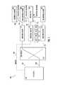
- FIG. 1is a functional block diagram illustrating a switched dual radiator antenna apparatus, in accordance with one exemplary implementation of the present disclosure.
- FIG. 2Ais a perspective view of the backside of a mobile communications device comprising the switched dual radiator antenna apparatus, in accordance with one exemplary implementation.
- FIG. 2Bis a detailed view of an exemplary metal cup radiator element for use with the mobile communications device of FIG. 2A .
- FIG. 2Cis a bottom view of the exemplary metal cup radiator element shown in FIG. 2B .
- FIG. 2Dis a detailed perspective view of the exemplary metal cup radiator element shown in FIGS. 2B and 2C .
- FIG. 2Eis a detailed perspective view of an exemplary feed configuration for the switched dual radiator antenna apparatus of FIG. 2A .
- FIG. 2Fis a detailed perspective view of an exemplary ground configuration for the switched dual radiator antenna apparatus of FIG. 2A .
- FIG. 3is an electrical schematic diagram illustrating tuning of the switched dual radiator antenna apparatus (e.g., of FIG. 1 ), in accordance with one implementation.
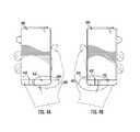
- FIG. 4Ais a graphical illustration depicting operational placement of the mobile communications device of, e.g., FIG. 2A , in the user right hand, in accordance with one implementation.
- FIG. 4Bis a graphical illustration depicting operational placement of the mobile communications device of, e.g., FIG. 2A in the user left hand, in accordance with one implementation.
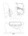
- FIG. 5is a graphical illustration depicting operational placement of the mobile communications device of, e.g., FIG. 2A in the user right hand and near the head, in accordance with one implementation.
- FIG. 6is a graphical illustration depicting operational placement of the mobile communications device of, e.g., FIG. 2A in the user left hand and near the head, in accordance with one implementation.
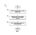
- FIG. 7is a logical flow diagram illustrating exemplary operation of the switched dual radiator antenna apparatus, in accordance with one or more implementations.
- FIG. 8is a logical flow diagram illustrating one embodiment of a radiator switching method for use with of the mobile communications apparatus of e.g., FIGS. 2A-2F .
- FIG. 9Adepicts free-space return loss (in dB) as a function of frequency for exemplary LTE 17 and LTE 12 bands, obtained using the exemplary antenna apparatus of FIG. 1 .
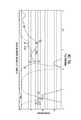
- FIG. 9Bdepicts free-space return loss (in dB) as a function of frequency for exemplary LTE 14, LTE 13, DCS1800, PCS1900 and WCDMA1 bands, obtained using the exemplary antenna apparatus of FIG. 1 .
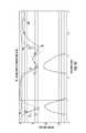
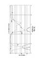
- FIG. 9Cdepicts free-space return loss (in dB) as a function of frequency for an exemplary LTE 20 band, obtained using the exemplary antenna apparatus of FIG. 1 .
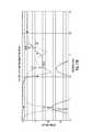
- FIG. 9Ddepicts free-space return loss (in dB) as a function of frequency for exemplary GSM 850 and GSM 900 bands, obtained using the exemplary antenna apparatus of FIG. 1 .
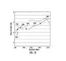
- FIG. 10is a plot of total free space efficiency as a function of frequency, obtained using the exemplary antenna apparatus of FIG. 1 .
- FIG. 11is a plot of total envelope correlation coefficient as a function of frequency obtained using the exemplary antenna apparatus of FIG. 1 .
- FIG. 12Adepicts loss (in dB) as a function of frequency for the LTE 17 and LTE 12 operating bands, obtained using the mobile device configuration shown in FIG. 6 ; i.e., head with hand, left cheek (BHHL).
- FIG. 12Bdepicts loss (in dB) as a function of frequency for the LTE 14, LTE 13, DCS 1800, PCS 1900 and WCDMA1 operating bands, obtained using the mobile device configuration shown in FIG. 6 ; i.e., head with hand, left cheek (BHHL).
- FIG. 12Cdepicts loss (in dB) as a function of frequency for the LTE 20 operating band, obtained using the mobile device configuration shown in FIG. 6 ; i.e., head with hand, left cheek (BHHL).
- FIG. 12Ddepicts loss (in dB) as a function of frequency for the GSM 850 and GSM 900 operating bands, obtained using the mobile device configuration shown in FIG. 6 ; i.e., head with hand, left cheek (BHHL).
- FIG. 13Adepicts loss (in dB) as a function of frequency for the LTE 17 and LTE 12 operating bands, obtained using the mobile device configuration shown in FIG. 5 ; i.e., head with hand, right cheek (BHHR).
- BHHRright cheek
- FIG. 13Bdepicts loss (in dB) as a function of frequency for the LTE 14, LTE 13, DCS 1800, PCS 1900 and WCDMA1 operating bands, obtained using the mobile device configuration shown in FIG. 5 ; i.e., head with hand, right cheek (BHHR).
- LTE 14, LTE 13, DCS 1800, PCS 1900 and WCDMA1 operating bandsobtained using the mobile device configuration shown in FIG. 5 ; i.e., head with hand, right cheek (BHHR).
- FIG. 13Cdepicts loss (in dB) as a function of frequency for the LTE 20 operating band, obtained using the mobile device configuration shown in FIG. 5 ; i.e., head with hand, right cheek (BHHR).
- BHHRright cheek
- FIG. 13Ddepicts loss (in dB) as a function of frequency for the GSM 850 and GSM 900 operating bands, obtained using the mobile device configuration shown in FIG. 5 ; i.e., head with hand, right cheek (BHHR).
- FIG. 14Aantenna efficiency (in dB) as a function of frequency obtained using the mobile device configuration shown in FIG. 6 ; i.e., head with hand, left cheek (BHHL).
- FIG. 14Bantenna efficiency (in dB) as a function of frequency obtained using the mobile device configuration shown in FIG. 5 ; i.e., head with hand, right check (BHHR).
- BHHRright check
- the terms “antenna,” “antenna element”, and “antenna system,”refer without limitation to any apparatus that incorporates a single element, multiple elements, or one or more arrays of elements that receive/transmit and/or propagate one or more frequency bands of electromagnetic radiation.
- the radiationmay be of numerous types, e.g., microwave, millimeter wave, radio frequency, digital modulated, analog, analog/digital encoded, digitally encoded millimeter wave energy, or the like.
- the energymay be transmitted from location to another location, using, one or more repeater links, and one or more locations may be mobile, stationary, or fixed to a location on earth such as a base station.
- a substraterefer generally and without limitation to any substantially planar or curved surface or component upon which other material and/or components can be disposed.
- a substratemay comprise a single or multi-layered printed circuit board (e.g., FR4), a semi-conductive die or wafer, or even a surface of a housing or other device component, and may be substantially rigid or alternatively at least somewhat flexible.
- frequency rangeAs used herein, the terms “frequency range”, “frequency band”, and “frequency domain” refer without limitation to any frequency range for communicating signals. Such signals may be communicated pursuant to one or more standards or wireless air interfaces.
- the terms “portable device”, “mobile device”, “client device”, “portable wireless device”, and “host device”include, but are not limited to, personal computers (PCs) and minicomputers, whether desktop, laptop, or otherwise, set-top boxes, personal digital assistants (PDAs), handheld computers, tablets, “smart” watches, personal communicators, tablet computers, portable navigation aids, J2ME equipped devices, cellular telephones, smartphones, personal integrated communication or entertainment devices, or literally any other device capable of interchanging data with a network or another device.
- PCspersonal computers
- PDAspersonal digital assistants
- handheld computerstablets
- “smart” watchespersonal communicators
- tablet computersportable navigation aids
- J2ME equipped devicesJ2ME equipped devices
- cellular telephonessmartphones
- personal integrated communication or entertainment devicesor literally any other device capable of interchanging data with a network or another device.
- the terms “radiator,” and “radiating element”refer without limitation to an element that can function as part of a system that receives and/or transmits radio-frequency electromagnetic radiation; e.g., an antenna.
- RF feedrefers without limitation to any energy conductor and coupling element(s) that can transfer energy, transform impedance, enhance performance characteristics, and conform impedance properties between incoming/outgoing RF energy signals to that of one or more connective elements, such as for example a radiator.
- topAs used herein, the terms “top”, “bottom”, “side”, “up”, “down”, “left”, “right”, “back”, “front”, and the like merely connote a relative position or geometry of one component to another, and in no way connote an absolute frame of reference or any required orientation. For example, a “top” portion of a component may actually reside below a “bottom” portion when the component is mounted to another device (e.g., to the underside of a PCB).
- wirelessmeans any wireless signal, data, communication, or other interface including without limitation Wi-Fi, Bluetooth, 3G (e.g., 3GPP, 3GPP2, and UMTS), HSDPA/HSUPA, TDMA, CDMA (e.g., IS-95A, WCDMA, etc.), FHSS, DSSS, GSM, PAN/802.15, WiMAX (802.16), 802.20, narrowband/FDMA, OFDM, PCS/DCS, Long Term Evolution (LTE) or LTE-Advanced (LTE-A), analog cellular, NFC/RFID, CDPD, satellite systems such as GPS, millimeter wave or microwave systems, optical, acoustic, and infrared (i.e., IrDA).
- 3Ge.g., 3GPP, 3GPP2, and UMTS
- HSDPA/HSUPAe.g., TDMA
- CDMAe.g., IS-95A, WCDMA, etc.
- the present disclosureprovides, inter alia, a switchable multi-radiator high-band antenna apparatus, and methods of tuning and utilizing the same.
- An exemplary embodiment of the antenna apparatusmay be configured to operate in dual (i.e., lower and upper) frequency bands, so as to facilitate use within a handheld mobile communications device (e.g., cellular telephone or smartphone).
- the mobile communications devicemay comprise at least partly, a metal enclosure configured to house the antenna and the radio frequency (RF) electronics “engine” (e.g., transceiver).
- the antenna apparatusin one embodiment includes a metal cup, two feeding structures, a switching element, and a ground element.
- One feeding structuremay be used to tune the antenna in both the lower (e.g., GSM850, E-GSM900, LTE12, LTE 17, and/or other) and the upper band frequencies (e.g., DCS1800, WCDMA1, LTE7, and/or other).
- the other feed structuremay be used to tune the antenna in the upper band.
- Frequency tuning of the antenna feed structuresmay be effectuated via respective impedance matching circuits.
- the switching elementis in one variant configured to direct signal routing from the RF engine to one of the two feed structures (such as e.g., 700 MHz to 2170 MHz via the main feed, and 1710-2170 MHz for the alternate or high-band (HB) feed).
- a user's handmay cover one of the antenna elements (e.g., radiators that are proximate the first feeding structure). Responsive to a determination by the device electronics of reduced performance associated with the partially covered antenna element, the RF engine may direct the switching element to alter the feed signal route to the second feed structure.
- the automatic switching of the antenna active radiatoradvantageously mitigates antenna detuning due to proximity to the user's body (e.g., hand, and/or head) thereby user improving robustness of the mobile device communications and enhancing user experience.
- the antenna apparatus 100comprises an element 120 , first 130 and second 132 feeding structures (e.g., main and high band (HB) feed structures), and first and second ground elements 122 , 126 (see e.g., elements 218 and 222 , respectively, in FIG. 2F herein).
- first 130 and second 132 feeding structurese.g., main and high band (HB) feed structures
- first and second ground elements 122 , 126see e.g., elements 218 and 222 , respectively, in FIG. 2F herein.
- the first feed structure 130(also referred to as the main feed structure in this embodiment) may be utilized to tune the antenna 100 in both lower and upper band frequencies, and the second feed structure 132 only to high band. Impedance matching in this embodiment is made with matching circuits. Frequency tuning of the antenna feed structures 130 , 132 may be effectuated via impedance matching circuits 114 , 116 , respectively. One exemplary embodiment of the matching circuits 114 , 116 is shown and described with respect to FIG. 3 , below. Individual ones of the feed structures 130 , 132 are configured to cause an electromagnetic resonance in at least one band, e.g., W-CDMA 1 .
- the resonance from the exemplary feed structures 130 and 132can be seen in high band frequencies in the vicinity of 2000 MHz (PCS1900 and WCDMA1), with the same band for both feeds.
- the main antenna feedinguses all the possible frequencies from 700 MHz to 2170 MHz, while the HB antenna feed is used as an alternative signal path for frequencies from 1710-2170 MHz (such as when the main antenna is covered by the user's hand in the upper frequencies).
- the lower and/or the upper frequency bandsmay comprise one or more individual bands configured to support one or more communications standards (e.g., Global System for Mobile Communications (GSM), Long Term Evolution (LTE), Wideband Code Division Multiple Access (W-CDMA), Code Division Multiple Access (CDMA), and/or other standards.
- GSMGlobal System for Mobile Communications
- LTELong Term Evolution
- W-CDMAWideband Code Division Multiple Access
- CDMACode Division Multiple Access
- the lower frequency bandincludes one or more of the following: LTE 12 (698-746 MHz), LTE 17 (704 MHz to 746 MHz), LTE 13 (746 MHz to 787 MHz), LTE 14 (758 MHz to 798 MHz), LTE 20 (791 to 862 MHz), GSM850 (824 MHz to 894 MHz), E-GSM-900 (880 MHz to 960), and/or other bands
- the upper frequency bandincludes one or more of the following: DCS1800 (1710 MHz to 1880 MHz), PCS1900 (1850 MHz to 1990 MHz), WCDMA1 (1920 MHz to 2170 MHz), LTE 7 (2500 MHz to 2690 MHz) and/or other bands.
- the element 120may comprise a metal structure and/or plastic structure with one or more metallic (conductive) layers.
- the element 120includes a metallic “cup” forming a portion of the mobile device enclosure and configured to cover one lateral (e.g., the bottom) end of the mobile device.
- the element 120can be capacitively coupled to the feed structures 130 , 132 .
- the electromagnetic coupling 134 , 138 of the element 120is in the illustrated embodiment configured to cause at least two resonances, thereby effectuating radio communications in the respective frequency bands, e.g., LTE12/LTE17 lower bands, LTE 13/LTE14 upper bands, GSM 850/GSM 900 lower bands and/or other bands.
- the element 120may be isolated from the device metal enclosure and/or chassis (e.g., 210 in FIG. 2A ) by a slot (e.g., 204 in FIG. 2A ) or other approach.
- the slot 204is in the illustrated embodiment configured to cause at least one upper band resonance, thereby effectuating radio communications in the respective frequency band, e.g., DCS1800/PCS1900, and/or other bands.
- the exemplary mobile devicefurther includes a ground plane, e.g., disposed on a printed circuit board of the device.
- the cup element 120is coupled to the ground plane via first 118 and second ground 122 structures.
- the ground structure 122may comprise a solid or fixed ground characterized by a single connection state (e.g., always connected to ground via the same circuit).
- the solid ground structure 122comprises a metal strip 218 .
- the position of the solid ground 218may be used to select the antenna resonant frequency, and the width of the solid ground used to select the bandwidth of the antenna.
- a switched ground 202(see FIGS. 2A-2E ) is provided, and the structure 222 is tuned for WCDMA1-Rx (but can also be used to cover other frequencies, such as e.g., LTE7 frequencies).
- the exemplary ground structure 118includes a switched ground characterized by two or more connection states.
- the switched ground structure 118may comprise a switching circuit 128 configured to couple the element 120 to ground via one of four circuits 142 , 144 , 146 , 148 .
- the individual circuits 142 , 144 , 146 , 148are in one variant characterized by respective impedances configured to tune the element 120 to a given operating frequency band (e.g., LTE 12, LTE 17, LTE 13, LTE14, GSM850, GSM900, LTE 20, and/or other).
- the switching element 128may comprise for instance a single pole four throw switch (SP4T) controlled by the RF engine of the antenna apparatus (e.g., the RF chipset 102 ).
- the SP4T switch 128may be used to present different impedance values from antenna to ground. It will be appreciated by those skilled in the art given the present disclosure that the foregoing switching configuration (e.g., the switch type, number of input and/or output contacts, and/or frequency band composition) is exemplary, and various other switched ground implementations may be utilized consistent with the antenna application specifications.
- the ground element 126is in the exemplary embodiment configured to capacitively (electromagnetically) couple to the main feed structure 130 (shown by the arrow 136 in FIG. 1 ), and/or the high band (HB) feed structure 132 .
- the ground element 126may be tuned to comprise a parasitic element (e.g., passive radiator) at one or more upper band frequencies.
- the parasitic resonanceis tuned to WCDMA1-Rx frequencies.
- the antenna apparatus 100further comprises a switch 110 which in some implementations, is embodied as a two pole dual throw (DPDT) switch configured to be controlled by the RF engine 102 via a control line 104 .
- the RF enginemay direct the switching element 110 to alter the feed signal path from the path 112 to the signal path 108 as described in greater detail below.
- DPDTtwo pole dual throw
- FIGS. 2A through 2Fdepict an exemplary mobile communications device comprising the switched dual radiator antenna apparatus (e.g., the apparatus 100 described with respect to FIG. 1 , supra).
- the exemplary mobile communications device 200 of FIG. 2Aincludes a metal or partly metallic enclosure and/or chassis 210 .
- the antenna apparatusincludes a metallic element 220 (e.g., 120 in FIG. 1A ).
- the apparatus element 220is isolated from the enclosure 210 by e.g., a slot 204 or other mechanism.
- One resonancein the upper frequency band frequencies
- the slot widthhas been selected at 1 mm, thereby causing an upper band resonance at frequency bands associated with the exemplary DCS1800/PCS1900 standards.
- the foregoing slot configurationmay be adjusted in accordance with the antenna specification (e.g., the slot width may be selected between e.g., 0.1 mm and 5 mm) in order to tune the antenna as desired or required by a given application.
- the location denoted by arrow 202 in FIGS. 2A-2Ddenotes the switched ground location of the antenna apparatus (e.g., 118 in FIG. 1 ).
- FIGS. 2B-2Cillustrate dimensions and configuration of the exemplary metal cup radiator element 220 .
- the width 208 and height 214 of the element 220are in this implementation configured at 69.8 mm and 5 mm, respectively, e.g., commensurate with the device 200 enclosure 210 dimensions, although it will be appreciated that these values (and this radiator/enclosure relationship) are not a requirement.
- the element 220 depth 206 in the illustrated implementationis configured at 11 mm, although other values may be used as well.
- the cup element 220includes in this implementation an opening configured to accept a power and/or communications connector 212 (e.g., a micro USB connector).
- FIG. 2Eillustrates an exemplary feed configuration of a switched dual radiator antenna disposed in the portable communications device.
- the cup element 220is not shown in the isometric view depicted in FIG. 2E for clarity.
- the illustrated structures 230 , 232correspond to the main and the high-band (HB) antenna feed structures (e.g., the structures 130 , 132 described with respect to FIG. 1 above).
- the structures 230 , 232comprise metal strips of about 1.4 mm in width and 10.6 mm in length, although other values may be readily substituted.
- the feed structures 230 , 232may be spaced from one another by about 32 mm in the exemplary embodiment.
- the antenna feeding pointis typically placed at a location corresponding to about one-third (1 ⁇ 3) of the device total width.
- the middle point of the feed structureis 16.9 mm from the device edge, which is about one-fourth (1 ⁇ 4) of the device width, although other placements and positions are readily employed consistent with the present disclosure, the foregoing being merely
- FIG. 2Fillustrates an exemplary ground configuration of a switched dual radiator antenna disposed in the portable communications device.
- the cup element 220is not shown in the isometric view depicted in FIG. 2F for clarity.
- the elements 218 , 222are used for various functions. Specifically, in the exemplary embodiment, the position of the element 218 may be used to select the antenna resonant frequency, while the width of the element 218 may be used to select the bandwidth of the antenna (in the low band). Additionally, the solid ground 222 behaves as a parasitic resonator tuned to e.g., WCDMA1-Rx frequencies.
- FIG. 3illustrates an exemplary implementation of a tuning circuit for the switched multi-radiator antenna apparatus (e.g., the dual radiator apparatus of FIG. 1 ).
- the illustrated circuit 300includes tuning circuits 310 , 320 configured to tune the main and the HB antenna feed structures (e.g., 130 , 132 in FIG. 1 ), respectively.
- the circuit 310also includes a reactive circuit configured to adjust the impedance of a signal path between the RF engine (e.g., the block 102 in FIG. 1 ) main antenna feed port 312 and the antenna main antenna feed port 314 .
- the circuit 320 in this implementationincludes a reactive circuit configured to adjust impedance of a signal path between the RF engine HB antenna feed port 322 and the antenna HB antenna feed port 324 .
- the exemplary circuit 300comprises a switched ground block 340 configured to selectively couple the element 120 in FIG. 1 to the ground plane.
- the block 340in one embodiment includes a single pole four throw switch 330 controlled by the RF engine of the antenna apparatus (e.g., the RF chipset 102 ) via control line 356 .
- the switch 330is characterized by four states 332 , 334 , 336 , 338 that may be used to present different impedance values from the antenna port 350 to ground.
- the block 340may also comprise two or more reactive circuits 342 , 344 , 346 , 348 configured to adjust impedance of a signal path between the antenna port 350 and ground.
- FIG. 4Aillustrates an exemplary operational placement of a mobile communications device (e.g., the device 200 of FIG. 2A ), in the user's right hand.
- a mobile communications devicee.g., the device 200 of FIG. 2A
- the antenna radiator portion 402 proximate to the HB feed structure 432e.g., the structure 132 in FIG. 1 and/or the structure 232 in FIG. 2E
- This HB feed structure blockingmay cause detuning of the antenna in one or more upper frequency bands.
- the antenna detuningmay cause, inter alia, an increase signal return loss and/or a reduction in total antenna efficiency when communicating using the one or more upper frequency band.
- the device processing electronicsis configured in the exemplary implementation to detect the reduced antenna performance, and switch over the communication signal path from the HB feed structure 432 to the main antenna feed structure 430 . This signal path adjustment corresponds to the RF engine 102 directing the switching element 110 over the control line 104 to switch feed signal from the signal path 112 to the signal path 108 , shown in FIG. 1 .
- FIG. 4Billustrates an exemplary operational placement of a mobile communications device (e.g., the device 200 of FIG. 2A ), in the user's left hand.
- a mobile communications devicee.g., the device 200 of FIG. 2A
- the antenna radiator portion 422 proximate to the main feed structure 430e.g., the structure 130 in FIG. 1 and/or the structure 230 in FIG. 2E
- the user hand 424in contrast to the right-handed grasp of FIG. 4A , wherein the HB structure is partly blocked.
- the main feed structure blockingmay cause, inter alia, detuning of the antenna in one or more upper frequency bands.
- the antenna detuningmay cause an increase signal return loss and/or a reduction in total antenna efficiency when communicating using the one or more upper frequency bands.
- the device processing electronicsare in one implementation configured to detect the reduced antenna performance, and switch over the communication signal path from the main feed structure 430 to the HB antenna feed structure 432 . This signal path adjustment corresponds to the RF engine 102 directing the switching element 110 over the control line 104 to switch feed signal from the signal path 108 to the signal path 112 , shown in FIG. 1 .
- FIGS. 5-6illustrate exemplary scenarios of operational placement of a mobile communications device (e.g., the device 400 of FIGS. 4A-4B ), near the user's head, and in the user right or left hand, respectively.
- a mobile communications devicee.g., the device 400 of FIGS. 4A-4B
- the HB antenna radiator portionmay become at least partly blocked.
- the device 400 processing electronicsis configured to mitigate the partial antenna blocking by switching over the feed signal from the HB feed 432 to the main feed 430 .
- the main antenna radiator portionWhen the device 400 is placed in the user's left hand and near the user's head, the main antenna radiator portion may become at least partly blocked.
- the device 400 processing electronicsmitigates the partial antenna blocking by switching over the feed signal from the main feed 430 to the HB feed 432 .
- FIGS. 4A-6The operational configurations of the device 400 illustrated in FIGS. 4A-6 have been used by the Assignee hereof during simulation and testing of an exemplary antenna apparatus constructed according to one embodiment of the disclosure, as described in detail below with respect to FIGS. 9A-13 .
- FIGS. 7-8illustrate methods of operating an exemplary embodiment of the switched antenna apparatus of the disclosure, in accordance with one or more implementations.
- the operations of methods 700 , 800 presented beloware intended to be illustrative. In some implementations, methods 700 , 800 , may be accomplished with one or more additional operations not described, and/or without one or more of the operations discussed. Additionally, the order in which the operations of methods 700 , 800 are illustrated in FIGS. 7-8 described below is not intended to be limiting.
- methods 700 , 800may be implemented in one or more processing devices (e.g., a digital processor, an analog processor, a digital circuit designed to process information, an analog circuit designed to process information, a state machine, and/or other mechanisms for electronically processing information and/or execute computer program modules).
- the one or more processing devicesmay include one or more devices executing some or all of the operations of methods 700 , 800 in response to instructions stored electronically on an electronic storage medium.
- the one or more processing devicesmay include one or more devices configured through hardware, firmware, and/or software to be specifically designed for execution of one or more of the operations of methods 700 , 800 .
- FIG. 7illustrates operation of the exemplary switched dual radiator antenna apparatus.
- the steps of the method 700may be performed for example by a mobile communications device, such as that described above with respect to FIGS. 2A-2F , or by another entity, or by combinations thereof.
- a first antenna elementmay be operated in one or more upper frequency bands.
- the first antenna element operationcomprises energizing one of the feed structures 130 or 132 via the respective pathway 108 or 112 .
- the one or more upper frequency bandsmay include for example one or more of the following: DCS1800, PCS1900, WCDMA1, LTE 7, and/or other bands.
- a reduction in performance associated with the first antenna operationis determined.
- the antenna performance reductionmay be due to antenna radiator detuning caused by a user placing the device in their right/left hand and/or proximate their head, e.g., as described above with respect to FIGS. 4A-6 .
- a second antenna elementis operated in the one or more upper frequency bands.
- the second antenna element operationcomprises energizing the other one of the two feed structures 132 or 130 via the respective pathway 112 or 108 .
- the two feedsmay be operated simultaneously, such as e.g., in the case of a MIMO or other implementation with multiple transmission/receiving elements.
- FIG. 8illustrates an exemplary embodiment of a radiator switching method for use with of the mobile communications apparatus of e.g., FIG. 2 , in accordance with the present disclosure.
- a performance measure associated with the operation of a first antennamay be determined.
- the performance measuremay comprise antenna efficiency (e.g., of Eqn. 1) and/or a return loss.
- a determinationmay be made as to whether the antenna performance breached a threshold or acceptability criterion.
- the thresholdmay comprise minimum target efficiency, selected, for example at 15% (about ⁇ 8 dB). This exemplary value is selected based on the simulated BHH performances, although it will be appreciated that other values and/or selection criteria may be utilized.
- the performance of step 802may be determined instantaneously, or over a time interval such as one selected from the range between a first value and a second value (e.g., temporal averaging performed to identify sustained low performance), in some embodiments, or in other cases, over multiple different time intervals (and e.g., averaged).
- a time intervalsuch as one selected from the range between a first value and a second value (e.g., temporal averaging performed to identify sustained low performance), in some embodiments, or in other cases, over multiple different time intervals (and e.g., averaged).
- the methodproceeds to step 806 , wherein the first antenna element may be decoupled from the RF engine (e.g., element 102 in FIG. 1 ).
- a second antenna elementis coupled to the feed engine.
- the de-coupling/coupling operations of steps 806 / 808may be effectuated by the RF engine 102 directing the switching element 110 to alter the feed signal path from one of the paths (e.g., 108 or 112 ) to the other path (e.g., 112 or 108 ). This may occur substantially simultaneously if desired, or in a “break before make” type sequence so as to decouple the first element before the second element is coupled.
- FIGS. 9A through 14Bpresent performance results obtained during simulation and testing by the Assignee hereof of an exemplary antenna apparatus configured according to one or more embodiments described above with respect to FIGS. 1 and 2A-2F .
- FIGS. 9A-9Ddepict free-space return loss (in dB) as a function of frequency for the main S 11 (solid unmarked curves) and HB S 22 (solid curves marked with ‘x’) antenna radiators (e.g., comprising the feed structures 130 , 132 in FIG. 1 or 430, 432 in FIG. 4A ).
- the data in FIG. 9Acorrespond to antenna radiators operating in exemplary LTE 17 and LTE 12 bands.
- Data in FIG. 9Bcorrespond to antenna radiators operating in exemplary LTE 14, LTE 13, DCS1800, PCS1900, and WCDMA1 bands.
- the data in FIG. 9Ccorrespond to antenna radiators operating in an exemplary LTE 20 band.
- FIGS. 9Dcorrespond to antenna radiators operating in exemplary GSM 850 and GSM900 bands.
- the curves marked with designators 900 , 910 , 920 , 930 in FIGS. 9A-9Ddenote the performance of the main antenna radiator (e.g., 130 in FIG. 1 ), while the curves marked with designators 902 , 912 , 922 , 932 in FIGS. 9A-9D denote the performance of the HB antenna radiator (e.g., 132 in FIG. 1 ).
- FIG. 10presents data regarding free-space efficiency obtained for the same antenna apparatus as described above with respect to FIGS. 9A-9D (e.g., the antenna 100 of FIG. 1 ).
- Efficiency of an antennais may be defined decimal logarithm of a ratio of radiated to input power:
- AntennaEfficiency10 ⁇ ⁇ log 10 ⁇ ( Radiated ⁇ ⁇ Power Input ⁇ ⁇ Power ) ( Eqn . ⁇ 1 )
- An efficiency of zero (0) dBcorresponds to an ideal theoretical radiator, wherein all of the input power is radiated in the form of electromagnetic energy.
- the curve marked with designator 1000 in FIG. 10corresponds to operating the main antenna feed (e.g., 130 in FIG. 1 ) in the upper frequency bands (e.g., DCS1800, PCS1900, WCDMA-1 bands).
- the curve marked with designator 1002 and a solid square marker in FIG. 10corresponds to operating the main antenna feed in the lower frequency (e.g., LTE 14, LTE 13) bands.
- the curve marked with designator 1004 and marker X in FIG. 10corresponds to operating the HB antenna feed (e.g., 132 in FIG.
- FIG. 11presents data regarding free-space envelope correlation coefficient efficiency for the same antenna apparatus as described above with respect to FIGS. 9A-9D (e.g., the antenna 100 of FIG. 1 ).
- the data presented in FIG. 11were obtained in upper frequency band between 1710 MHz and 2170 MHz.
- FIGS. 9A-10may be used as a reference when evaluating performance of the exemplary antenna operable in-hand and/or near the user's head, as described below with respect to FIGS. 12A-14B .
- FIGS. 12A-12Ddepict return loss (in dB) as a function of frequency obtained according to a CTIA v3.1 “beside head with hand, left cheek (BHHL)” measurement configuration.
- the data in FIG. 12Acorrespond to antenna radiators operating in LTE 17 and LTE 12 bands.
- the data in FIG. 12Bcorrespond to antenna radiators operating in LTE 14, LTE 13, DCS1800, PCS1900, and WCDMA1 bands.
- the data in FIG. 12Ccorrespond to antenna radiators operating in LTE 20 band.
- the data in FIG. 12Dcorrespond to antenna radiators operating in GSM 850 and GSM900 bands.
- 12A-12Ddenote the performance of the main antenna radiator (e.g., 430 in FIG. 6 ), while the curves marked with designators 1202 , 1212 , 1222 , 1232 in FIGS. 12A-12D denote the performance of the HB antenna radiator (e.g., 432 in FIG. 6 ).
- FIGS. 13A-13Ddepict return loss (in dB) as a function of frequency obtained according to CTIA v3.1 “beside head with hand, left cheek (BHHL)” measurement configuration.
- the data in FIG. 13Acorrespond to antenna radiators operating in LTE 17 and LTE 12 bands.
- the data in FIG. 13Bcorrespond to antenna radiators operating in LTE 14, LTE 13, DCS1800, PCS1900, and WCDMA1 bands.
- the data in FIG. 13Ccorrespond to antenna radiators operating in LTE 20 band.
- the data in FIG. 13Dcorrespond to antenna radiators operating in GSM 850 and GSM900 bands.
- 13A-13Ddenote the performance of the main antenna radiator (e.g., 430 in FIG. 5 ), while the curves marked with designators 1302 , 1313 , 1322 , 1332 in FIGS. 13A-13D denote the performance of the HB antenna radiator (e.g., 432 in FIG. 5 ).
- FIG. 14Apresents a comparison of data regarding antenna efficiency obtained in free space versus data obtained according to CTIA v3.1BHHL measurement configuration using the dual radiator antenna of, e.g., FIG. 1 (i.e., comprising main and HB radiators).
- the curves marked with designators 1400 through 1410 in FIG. 14Adepict antenna efficiency in free space.
- the curves marked with designators 1420 through 1430 in FIG. 14Adepict antenna efficiency for BHHL.
- the curves marked with designators 1400 and 1420present data obtained when operating the main antenna feed (e.g., 130 in FIG. 1 ) in upper frequency bands (e.g., DCS1800, PCS1900, WCDMA-1 bands).
- the curves marked with designator 1402 and a solid square marker and 1422 and an open square markercorresponds to operating the main antenna feed in lower frequency (e.g., LTE 14, LTE 13) bands.
- the curves marked with designator 1404 and marker X and designator 1414 and marker ‘ ⁇ X’correspond to operating the HB antenna feed (e.g., 132 in FIG. 1 ) in upper frequency (e.g., DCS1800, PCS1900, WCDMA-1) bands.
- the curves marked with designator 1406 and marker + and designator 1406 and marker ‘ ⁇ +’correspond to operating the main antenna feed in LTE 20 band.
- the curves marked with designator 1408 and solid circle marker and designator 1428 and open circle markercorrespond to operating the main antenna feed in GSM 850/GSM900 bands.
- the curves marked with designator 1410 and solid triangle marker and designator 1430 and open triangle markercorrespond to operating the main antenna feed in LTE 17/LTE 12 bands.
- FIG. 14Bpresents a comparison of data regarding antenna efficiency obtained in free space versus data obtained according to CTIA v3.BHHR measurement configuration using the dual radiator antenna of, e.g., FIG. 1 (i.e., comprising main and HB radiators).
- the curves marked with designators 1440 and 1460present data obtained when operating the main antenna feed (e.g., 130 in FIG. 1 ) in upper frequency bands (e.g., DCS1800, PCS1900, WCDMA-1 bands).
- the curves marked with designator 1442 and a solid square marker and 1462 and an open square markercorresponds to operating the main antenna feed in lower frequency (e.g., LTE 14, LTE 13) bands.
- the curves marked with designator 1444 and marker X and designator 1454 and marker ‘ ⁇ X’correspond to operating the HB antenna feed (e.g., 132 in FIG. 1 ) in upper frequency (e.g., DCS1800, PCS1900, WCDMA-1) bands.
- the curves marked with designator 1446 and marker + and designator 1466 and marker ‘ ⁇ +’correspond to operating the main antenna feed in LTE 20 band.
- the curves marked with designator 1448 and solid circle marker and designator 1468 and open circle markercorrespond to operating the main antenna feed in GSM 850/GSM900 bands.
- the curves marked with designator 1450 and solid triangle marker and designator 1470 and open triangle markercorrespond to operating the main antenna feed in LTE 17/LTE 12 bands.
- the lower band and upper band of the dedicated HB antenna(e.g., 432 in FIG. 5 ) become de-tuned when the antenna apparatus is placed in the user's right hand besides head, while the main antenna radiator (e.g., 430 in FIG. 5 ) HB radiator remains in-band.
- the HB antenna radiator BHHR performance reduction in the lower bandis between about 6 dB and about 9 dB, while in the upper frequency band, the reduction is between about 3 dB and 6 dB.
- the main antenna BHHL performance reduction in the lower bandis between about 6 dB and about 9 dB, while in the upper frequency band, the reduction is between about 3.5 dB and 5 dB.
- the present disclosureprovides for an antenna apparatus comprising multiple (e.g., dual) upper band radiators.
- the two radiatorsmay be configured to operate within one or more upper frequency bands (e.g., DCS1800, PCS1900, WCDMA1, LTE 7, and/or other) while being disposed within the same metal enclosure of a handheld communications device.
- the upper band radiator switching methodology described hereinenables inter alia, automatic switchover of a detuned antenna radiator to another radiator in order to maintain antenna performance when the device in placed in a user's hand and/or near a user's head. Placement of the two radiators within the same enclosure provides for a smaller and/or a lower cost device.
- the antenna switchover capability described hereinimproves antenna operational robustness, and enables the communications device to maintain uninterrupted communications while in-hand and/or beside the user's head.
Landscapes
- Engineering & Computer Science (AREA)
- Computer Networks & Wireless Communication (AREA)
- Signal Processing (AREA)
- Support Of Aerials (AREA)
- Variable-Direction Aerials And Aerial Arrays (AREA)
- Waveguide Aerials (AREA)
Abstract
Description
A portion of the disclosure of this patent document contains material that is subject to copyright protection. The copyright owner has no objection to the facsimile reproduction by anyone of the patent document or the patent disclosure, as it appears in the Patent and Trademark Office patent files or records, but otherwise reserves all copyright rights whatsoever.
The present disclosure relates generally to antenna apparatus for use in electronic devices such as for example wireless or portable radio devices, and more particularly in one exemplary aspect to a switchable multi-radiator high band antenna apparatus, and methods of producing, tuning and utilizing the same.
Internal antennas are an element found in most modern radio devices, such as mobile computers, mobile phones, Blackberry® devices, smartphones, tablet computers, personal digital assistants (PDAs), “smart” watches, or other personal communication devices (PCDs).
Typically, these antennas comprise one or more radiating elements disposed within the device enclosure. It is a common requirement that the antenna operate in more than one frequency band; e.g., both lower (such as for instance LTE12, LTE13, LTE17, LTE14, LTE20, GSM850, E-GSM900) and an upper band (such as DCS1800, PCS1900, WCDMA-1) frequencies.
Portable mobile devices often comprise enclosures that are, at least partly, fabricated from an electrically conductive material (e.g., metals or alloys). During handheld operation of the mobile device by a user, the antenna operating at upper band frequencies may be detuned due to interference from the user's hand and/or head. The antenna detuning may lead to reduced performance of the communication device, e.g., reduced range, reduced data rate, increased directionality, and/or link drop.
Accordingly, there is a salient need for an improved internal antenna apparatus capable of supporting operation at the lower and the upper frequencies while operating inside a metal enclosure that may be placed in a user's hand and/or near their head.
The present disclosure satisfies the foregoing needs by providing, inter alia, improved multiband antenna apparatus and methods useful in, e.g., mobile wireless devices.
In a first aspect, a multiband antenna apparatus is disclosed. In one embodiment, the apparatus is for use in a radio communications device, and includes: a radiator structure disposed to substantially envelop one lateral end of the device, and configured to be electrically connected to a ground plane of the device; a first and a second feed structure configured to be selectively connected to a radio frequency feed port; and a ground structure, configured to be electrically connected to the ground plane.
In one variant, the first feed structure is configured to effectuate radio frequency communications within at least one upper frequency band and at least one lower frequency band; and the second feed structure is configured to effectuate radio frequency communications within the at least one upper frequency band.
In another variant, the apparatus further includes a selector apparatus configured to selectively electrically connect one of (i) the first feed structure, or (ii) the second feed structure, to the feed port.
In another variant, the ground plane is connected via first and second ground elements, the second ground element configured to be connected to the ground plane via a switching circuit comprising two or more alternate electrical signal paths each comprising a reactive circuit characterized by a respective impedance value that enables selective tuning of an operational band of the radiator structure.
In a further variant, the first ground element comprises a static ground element characterized by a single connection state; the first feed structure comprises a first matching circuit configured to be coupled to the feed port, and to tune the antenna operation to the at least one upper frequency band; and the second feed structure comprises a second matching circuit configured to be coupled to the feed port, and to tune the antenna operation to the at least one upper frequency band.
In another aspect of the disclosure, a method of mitigating effects of user interference on a radio signal emitting and receiving mobile device is disclosed. In one embodiment, the mobile device is characterized by first and second user grasping locations, and the method includes: energizing a first antenna feed structure with a radio signal comprising at least a first frequency component, the first antenna feed structure being encompassed by a radiating element disposed proximate one end of the device; and determining a performance measure associated with a received signal at the first frequency by the radiating element. In one variant, the method further includes, based at least on the performance measure not meeting one or more prescribed criteria: de-energizing the first antenna feed structure; and energizing a second antenna feed structure with a radio signal comprising at the least first frequency component; the second antenna feed structure being encompassed by the radiating element.
In another variant, the first grasping location corresponds to a user's hand covering at least partly the radiating element proximate the antenna feed structure; and the energizing the second antenna feed structure and de-energizing the first antenna feed structure cooperate to effectuate the mitigation of the user interference.
In a further variant, the determining the performance measure comprises: causing radiation of a first signal magnitude via the first feed structure; and evaluating a threshold and a second signal magnitude received via the first feed structure.
In another aspect, a multi-band antenna apparatus is disclosed. In one embodiment, the apparatus includes: a first radiating element in communication with a first feed structure; a second radiating element in communication with a second feed structure; and logic, in operative communication with the first and second feed structures, to selectively cause feeding of one of the first and second radiating elements based on detection of a reduction in performance of the other of the first and second radiating elements due to proximity to part of a user's anatomy.
In a further aspect, a mobile radio frequency communication device is disclosed. In one embodiment, the device includes: an enclosure and an electronics assembly contained substantially therein, said electronics assembly comprising a ground plane and a first and a second feed port; and a multiband antenna apparatus. In one variant, the antenna apparatus includes: a metal cup structure disposed proximate one end of the enclosure and configured to be electrically connected to the ground plane via a first and a second ground element; a first and a second feed structure; a ground structure configured to be electrically connected to the ground plane; and a selector apparatus configured to selectively electrically connect one of (i) the first feed structure to the first feed port or (ii) the second feed structure to the second feed port.
In another variant, the first feed structure is configured to effectuate the radio frequency communications within at least one high frequency band and at least one low frequency band; the second feed structure is configured to effectuate the radio frequency communications within the at least one high frequency band; the enclosure comprises a chassis and the cup, the cup being electrically separated from the chassis by a non-conductive slot thereby forming an operational antenna portion, the operational portion configured to form a first electromagnetic resonance in at least a second high frequency band; the second ground element is configured to be connected to the ground plane via a switching circuit comprising two or more alternate electrical signal paths; and the metal cup structure is configured to form a second electromagnetic resonance in at least a fourth and a third frequency bands.
In another aspect of the disclosure, a method of tuning the antenna apparatus is disclosed.
In yet a further aspect, a method of operating the antenna apparatus is disclosed.
In yet another aspect, a tuning circuit is disclosed. In one embodiment, the tuning circuit is configured for use with a multi-band antenna in a mobile wireless device.
Further features of the present disclosure, its nature and various advantages will be more apparent from the accompanying drawings and the following detailed description.
The features, objectives, and advantages of the disclosure will become more apparent from the detailed description set forth below when taken in conjunction with the drawings, wherein:
All Figures disclosed herein are © Copyright 2013 Pulse Finland Oy. All rights reserved.
Reference is now made to the drawings wherein like numerals refer to like parts throughout.
As used herein, the terms “antenna,” “antenna element”, and “antenna system,” refer without limitation to any apparatus that incorporates a single element, multiple elements, or one or more arrays of elements that receive/transmit and/or propagate one or more frequency bands of electromagnetic radiation. The radiation may be of numerous types, e.g., microwave, millimeter wave, radio frequency, digital modulated, analog, analog/digital encoded, digitally encoded millimeter wave energy, or the like. The energy may be transmitted from location to another location, using, one or more repeater links, and one or more locations may be mobile, stationary, or fixed to a location on earth such as a base station.
As used herein, the terms “board” and “substrate” refer generally and without limitation to any substantially planar or curved surface or component upon which other material and/or components can be disposed. For example, a substrate may comprise a single or multi-layered printed circuit board (e.g., FR4), a semi-conductive die or wafer, or even a surface of a housing or other device component, and may be substantially rigid or alternatively at least somewhat flexible.
As used herein, the terms “frequency range”, “frequency band”, and “frequency domain” refer without limitation to any frequency range for communicating signals. Such signals may be communicated pursuant to one or more standards or wireless air interfaces.
As used herein, the terms “portable device”, “mobile device”, “client device”, “portable wireless device”, and “host device” include, but are not limited to, personal computers (PCs) and minicomputers, whether desktop, laptop, or otherwise, set-top boxes, personal digital assistants (PDAs), handheld computers, tablets, “smart” watches, personal communicators, tablet computers, portable navigation aids, J2ME equipped devices, cellular telephones, smartphones, personal integrated communication or entertainment devices, or literally any other device capable of interchanging data with a network or another device.
As used herein, the terms “radiator,” and “radiating element” refer without limitation to an element that can function as part of a system that receives and/or transmits radio-frequency electromagnetic radiation; e.g., an antenna.
As used herein, the terms “RF feed”, “feed” and “feed conductor” refer without limitation to any energy conductor and coupling element(s) that can transfer energy, transform impedance, enhance performance characteristics, and conform impedance properties between incoming/outgoing RF energy signals to that of one or more connective elements, such as for example a radiator.
As used herein, the terms “top”, “bottom”, “side”, “up”, “down”, “left”, “right”, “back”, “front”, and the like merely connote a relative position or geometry of one component to another, and in no way connote an absolute frame of reference or any required orientation. For example, a “top” portion of a component may actually reside below a “bottom” portion when the component is mounted to another device (e.g., to the underside of a PCB).
As used herein, the term “wireless” means any wireless signal, data, communication, or other interface including without limitation Wi-Fi, Bluetooth, 3G (e.g., 3GPP, 3GPP2, and UMTS), HSDPA/HSUPA, TDMA, CDMA (e.g., IS-95A, WCDMA, etc.), FHSS, DSSS, GSM, PAN/802.15, WiMAX (802.16), 802.20, narrowband/FDMA, OFDM, PCS/DCS, Long Term Evolution (LTE) or LTE-Advanced (LTE-A), analog cellular, NFC/RFID, CDPD, satellite systems such as GPS, millimeter wave or microwave systems, optical, acoustic, and infrared (i.e., IrDA).
Overview
The present disclosure provides, inter alia, a switchable multi-radiator high-band antenna apparatus, and methods of tuning and utilizing the same. An exemplary embodiment of the antenna apparatus may be configured to operate in dual (i.e., lower and upper) frequency bands, so as to facilitate use within a handheld mobile communications device (e.g., cellular telephone or smartphone). The mobile communications device may comprise at least partly, a metal enclosure configured to house the antenna and the radio frequency (RF) electronics “engine” (e.g., transceiver). The antenna apparatus in one embodiment includes a metal cup, two feeding structures, a switching element, and a ground element. One feeding structure may be used to tune the antenna in both the lower (e.g., GSM850, E-GSM900, LTE12,LTE 17, and/or other) and the upper band frequencies (e.g., DCS1800, WCDMA1, LTE7, and/or other). The other feed structure may be used to tune the antenna in the upper band. Frequency tuning of the antenna feed structures may be effectuated via respective impedance matching circuits. The switching element is in one variant configured to direct signal routing from the RF engine to one of the two feed structures (such as e.g., 700 MHz to 2170 MHz via the main feed, and 1710-2170 MHz for the alternate or high-band (HB) feed).
During device operation, a user's hand may cover one of the antenna elements (e.g., radiators that are proximate the first feeding structure). Responsive to a determination by the device electronics of reduced performance associated with the partially covered antenna element, the RF engine may direct the switching element to alter the feed signal route to the second feed structure. The automatic switching of the antenna active radiator advantageously mitigates antenna detuning due to proximity to the user's body (e.g., hand, and/or head) thereby user improving robustness of the mobile device communications and enhancing user experience.
Detailed descriptions of the various embodiments and variants of the apparatus and methods of the disclosure are now provided. While primarily discussed in the context of mobile devices, the various apparatus and methodologies discussed herein are not so limited. In fact, many of the apparatus and methodologies described herein are useful in any number of other antenna applications, whether associated with mobile or fixed devices, cellular or otherwise.
Moreover, while primarily described in the exemplary context of a dual (two) radiator apparatus, the various principles of the disclosure can be readily extended and applied to implementations having three or more radiators. e.g., tri-band, quad-band, etc.
Exemplary Antenna Element Apparatus and Methods
Referring now toFIGS. 1 through 2 , exemplary embodiments of the switched multi-radiator radio antenna apparatus of the disclosure are described in detail. One exemplary implementation of the switched antenna apparatus for use in a mobile radio device is presented inFIG. 1 . As shown, theantenna apparatus 100 comprises anelement 120, first130 and second132 feeding structures (e.g., main and high band (HB) feed structures), and first andsecond ground elements 122,126 (see e.g.,elements FIG. 2F herein).
The first feed structure130 (also referred to as the main feed structure in this embodiment) may be utilized to tune theantenna 100 in both lower and upper band frequencies, and thesecond feed structure 132 only to high band. Impedance matching in this embodiment is made with matching circuits. Frequency tuning of theantenna feed structures impedance matching circuits circuits FIG. 3 , below. Individual ones of thefeed structures CDMA 1. For example, the resonance from theexemplary feed structures
The lower and/or the upper frequency bands may comprise one or more individual bands configured to support one or more communications standards (e.g., Global System for Mobile Communications (GSM), Long Term Evolution (LTE), Wideband Code Division Multiple Access (W-CDMA), Code Division Multiple Access (CDMA), and/or other standards. In some implementations, the lower frequency band includes one or more of the following: LTE 12 (698-746 MHz), LTE 17 (704 MHz to 746 MHz), LTE 13 (746 MHz to 787 MHz), LTE 14 (758 MHz to 798 MHz), LTE 20 (791 to 862 MHz), GSM850 (824 MHz to 894 MHz), E-GSM-900 (880 MHz to 960), and/or other bands, and the upper frequency band includes one or more of the following: DCS1800 (1710 MHz to 1880 MHz), PCS1900 (1850 MHz to 1990 MHz), WCDMA1 (1920 MHz to 2170 MHz), LTE 7 (2500 MHz to 2690 MHz) and/or other bands. Various other combinations or permutations of the foregoing (and in fact others) will be recognized by those of ordinary skill given the present disclosure.
Theelement 120 may comprise a metal structure and/or plastic structure with one or more metallic (conductive) layers. In some implementations, e.g., such as those illustrated and described with respect toFIGS. 2A-2B , theelement 120 includes a metallic “cup” forming a portion of the mobile device enclosure and configured to cover one lateral (e.g., the bottom) end of the mobile device. Theelement 120 can be capacitively coupled to thefeed structures electromagnetic coupling element 120 is in the illustrated embodiment configured to cause at least two resonances, thereby effectuating radio communications in the respective frequency bands, e.g., LTE12/LTE17 lower bands,LTE 13/LTE14 upper bands,GSM 850/GSM 900 lower bands and/or other bands.
Theelement 120 may be isolated from the device metal enclosure and/or chassis (e.g.,210 inFIG. 2A ) by a slot (e.g.,204 inFIG. 2A ) or other approach. Theslot 204 is in the illustrated embodiment configured to cause at least one upper band resonance, thereby effectuating radio communications in the respective frequency band, e.g., DCS1800/PCS1900, and/or other bands.
The exemplary mobile device further includes a ground plane, e.g., disposed on a printed circuit board of the device. Thecup element 120 is coupled to the ground plane via first118 andsecond ground 122 structures. Theground structure 122 may comprise a solid or fixed ground characterized by a single connection state (e.g., always connected to ground via the same circuit). In some implementations, e.g., as shown inFIG. 2F , thesolid ground structure 122 comprises ametal strip 218. The position of thesolid ground 218 may be used to select the antenna resonant frequency, and the width of the solid ground used to select the bandwidth of the antenna. In the illustrated embodiment, a switched ground202 (seeFIGS. 2A-2E ) is provided, and thestructure 222 is tuned for WCDMA1-Rx (but can also be used to cover other frequencies, such as e.g., LTE7 frequencies).
Theexemplary ground structure 118 includes a switched ground characterized by two or more connection states. In some implementations, e.g., such as shown inFIG. 1 , the switchedground structure 118 may comprise aswitching circuit 128 configured to couple theelement 120 to ground via one of fourcircuits individual circuits element 120 to a given operating frequency band (e.g.,LTE 12,LTE 17,LTE 13, LTE14, GSM850, GSM900,LTE 20, and/or other). The switchingelement 128 may comprise for instance a single pole four throw switch (SP4T) controlled by the RF engine of the antenna apparatus (e.g., the RF chipset102). TheSP4T switch 128 may be used to present different impedance values from antenna to ground. It will be appreciated by those skilled in the art given the present disclosure that the foregoing switching configuration (e.g., the switch type, number of input and/or output contacts, and/or frequency band composition) is exemplary, and various other switched ground implementations may be utilized consistent with the antenna application specifications.
Theground element 126 is in the exemplary embodiment configured to capacitively (electromagnetically) couple to the main feed structure130 (shown by thearrow 136 inFIG. 1 ), and/or the high band (HB)feed structure 132. Theground element 126 may be tuned to comprise a parasitic element (e.g., passive radiator) at one or more upper band frequencies. In the antenna embodiment described with respect toFIGS. 1, 2A-2F , the parasitic resonance is tuned to WCDMA1-Rx frequencies.
Theantenna apparatus 100 further comprises aswitch 110 which in some implementations, is embodied as a two pole dual throw (DPDT) switch configured to be controlled by theRF engine 102 via acontrol line 104. The RF engine may direct theswitching element 110 to alter the feed signal path from thepath 112 to thesignal path 108 as described in greater detail below.
The exemplarymobile communications device 200 ofFIG. 2A includes a metal or partly metallic enclosure and/orchassis 210. The antenna apparatus includes a metallic element220 (e.g.,120 inFIG. 1A ). Theapparatus element 220 is isolated from theenclosure 210 by e.g., aslot 204 or other mechanism. One resonance (in the upper frequency band frequencies) may be excited from theslot 204. In the implementation illustrated inFIGS. 2A-2B, 2D , the slot width has been selected at 1 mm, thereby causing an upper band resonance at frequency bands associated with the exemplary DCS1800/PCS1900 standards. It will be appreciated by those skilled in the art that the foregoing slot configuration may be adjusted in accordance with the antenna specification (e.g., the slot width may be selected between e.g., 0.1 mm and 5 mm) in order to tune the antenna as desired or required by a given application.
The location denoted byarrow 202 inFIGS. 2A-2D denotes the switched ground location of the antenna apparatus (e.g.,118 inFIG. 1 ).
Theexemplary circuit 300 comprises a switchedground block 340 configured to selectively couple theelement 120 inFIG. 1 to the ground plane. Theblock 340 in one embodiment includes a single pole four throw switch330 controlled by the RF engine of the antenna apparatus (e.g., the RF chipset102) viacontrol line 356. The switch330 is characterized by fourstates antenna port 350 to ground. Theblock 340 may also comprise two or morereactive circuits antenna port 350 and ground.
When thedevice 400 is placed in the user's left hand and near the user's head, the main antenna radiator portion may become at least partly blocked. Thedevice 400 processing electronics mitigates the partial antenna blocking by switching over the feed signal from themain feed 430 to theHB feed 432.
The operational configurations of thedevice 400 illustrated inFIGS. 4A-6 have been used by the Assignee hereof during simulation and testing of an exemplary antenna apparatus constructed according to one embodiment of the disclosure, as described in detail below with respect toFIGS. 9A-13 .
In some implementations,methods methods methods
Atstep 702 of method700 a first antenna element may be operated in one or more upper frequency bands. In some implementations, the first antenna element operation comprises energizing one of thefeed structures respective pathway
Atstep 704, a reduction in performance associated with the first antenna operation is determined. In certain cases, the antenna performance reduction may be due to antenna radiator detuning caused by a user placing the device in their right/left hand and/or proximate their head, e.g., as described above with respect toFIGS. 4A-6 .
Atstep 706, a second antenna element is operated in the one or more upper frequency bands. In certain implementations, the second antenna element operation comprises energizing the other one of the twofeed structures respective pathway
It will also be appreciated that in certain implementations, the two feeds may be operated simultaneously, such as e.g., in the case of a MIMO or other implementation with multiple transmission/receiving elements.
Atstep 802 of themethod 800, a performance measure associated with the operation of a first antenna may be determined. In one or more implementations, the performance measure may comprise antenna efficiency (e.g., of Eqn. 1) and/or a return loss.
Atstep 804, a determination may be made as to whether the antenna performance breached a threshold or acceptability criterion. In one or more implementations, the threshold may comprise minimum target efficiency, selected, for example at 15% (about −8 dB). This exemplary value is selected based on the simulated BHH performances, although it will be appreciated that other values and/or selection criteria may be utilized.
The performance ofstep 802 may be determined instantaneously, or over a time interval such as one selected from the range between a first value and a second value (e.g., temporal averaging performed to identify sustained low performance), in some embodiments, or in other cases, over multiple different time intervals (and e.g., averaged).
Responsive to a determination that the performance has breached the threshold/criterion, the method proceeds to step806, wherein the first antenna element may be decoupled from the RF engine (e.g.,element 102 inFIG. 1 ).
Atstep 808, a second antenna element is coupled to the feed engine. In some embodiments, the de-coupling/coupling operations ofsteps 806/808 may be effectuated by theRF engine 102 directing theswitching element 110 to alter the feed signal path from one of the paths (e.g.,108 or112) to the other path (e.g.,112 or108). This may occur substantially simultaneously if desired, or in a “break before make” type sequence so as to decouple the first element before the second element is coupled.
Performance
The data presented inFIGS. 9A-9D depict free-space return loss (in dB) as a function of frequency for the main S11 (solid unmarked curves) and HB S22 (solid curves marked with ‘x’) antenna radiators (e.g., comprising thefeed structures FIG. 1 or 430, 432 inFIG. 4A ). The data inFIG. 9A correspond to antenna radiators operating inexemplary LTE 17 andLTE 12 bands. Data inFIG. 9B correspond to antenna radiators operating inexemplary LTE 14,LTE 13, DCS1800, PCS1900, and WCDMA1 bands. The data inFIG. 9C correspond to antenna radiators operating in anexemplary LTE 20 band. The data inFIG. 9D correspond to antenna radiators operating inexemplary GSM 850 and GSM900 bands. The curves marked withdesignators FIGS. 9A-9D denote the performance of the main antenna radiator (e.g.,130 inFIG. 1 ), while the curves marked withdesignators FIGS. 9A-9D denote the performance of the HB antenna radiator (e.g.,132 inFIG. 1 ).
An efficiency of zero (0) dB corresponds to an ideal theoretical radiator, wherein all of the input power is radiated in the form of electromagnetic energy.
The curve marked with designator1000 inFIG. 10 corresponds to operating the main antenna feed (e.g.,130 inFIG. 1 ) in the upper frequency bands (e.g., DCS1800, PCS1900, WCDMA-1 bands). The curve marked withdesignator 1002 and a solid square marker inFIG. 10 corresponds to operating the main antenna feed in the lower frequency (e.g.,LTE 14, LTE 13) bands. The curve marked withdesignator 1004 and marker X inFIG. 10 corresponds to operating the HB antenna feed (e.g.,132 inFIG. 1 ) in the upper frequency (e.g., DCS1800, PCS1900, WCDMA-1) bands, while the curves marked withdesignators 1006 and marker +,designator 1008 and marker O, anddesignator 1010 and solid triangle marker correspond to operating the main antenna feed in the (i)LTE 20, (ii)GSM 850/GSM900 and (iii) LTE17/LTE12 lower frequency bands, respectively.
The data presented inFIGS. 9A-10 may be used as a reference when evaluating performance of the exemplary antenna operable in-hand and/or near the user's head, as described below with respect toFIGS. 12A-14B .
The curves marked with designators1400 through1410 inFIG. 14A depict antenna efficiency in free space. The curves marked withdesignators 1420 through1430 inFIG. 14A depict antenna efficiency for BHHL. The curves marked withdesignators 1400 and1420 present data obtained when operating the main antenna feed (e.g.,130 inFIG. 1 ) in upper frequency bands (e.g., DCS1800, PCS1900, WCDMA-1 bands). The curves marked withdesignator 1402 and a solid square marker and1422 and an open square marker corresponds to operating the main antenna feed in lower frequency (e.g.,LTE 14, LTE 13) bands. The curves marked withdesignator 1404 and marker X anddesignator 1414 and marker ‘−X’ correspond to operating the HB antenna feed (e.g.,132 inFIG. 1 ) in upper frequency (e.g., DCS1800, PCS1900, WCDMA-1) bands. The curves marked withdesignator 1406 and marker + anddesignator 1406 and marker ‘−+’ correspond to operating the main antenna feed inLTE 20 band. The curves marked with designator1408 and solid circle marker and designator1428 and open circle marker correspond to operating the main antenna feed inGSM 850/GSM900 bands. The curves marked with designator1410 and solid triangle marker anddesignator 1430 and open triangle marker correspond to operating the main antenna feed inLTE 17/LTE 12 bands.
As may be seen from the data presented inFIGS. 12A-14B , the lower band and upper band of the dedicated HB antenna (e.g.,432 inFIG. 5 ) become de-tuned when the antenna apparatus is placed in the user's right hand besides head, while the main antenna radiator (e.g.,430 inFIG. 5 ) HB radiator remains in-band. The HB antenna radiator BHHR performance reduction in the lower band is between about 6 dB and about 9 dB, while in the upper frequency band, the reduction is between about 3 dB and 6 dB.
When the antenna apparatus is placed in the left hand besides left cheek (BHHL), the lower band and upper band of the main antenna radiator (e.g.,430 inFIG. 6 ) become de-tuned, while the HB radiator remains in band. The main antenna BHHL performance reduction in the lower band is between about 6 dB and about 9 dB, while in the upper frequency band, the reduction is between about 3.5 dB and 5 dB.
The present disclosure provides for an antenna apparatus comprising multiple (e.g., dual) upper band radiators. The two radiators may be configured to operate within one or more upper frequency bands (e.g., DCS1800, PCS1900, WCDMA1, LTE 7, and/or other) while being disposed within the same metal enclosure of a handheld communications device. The upper band radiator switching methodology described herein enables inter alia, automatic switchover of a detuned antenna radiator to another radiator in order to maintain antenna performance when the device in placed in a user's hand and/or near a user's head. Placement of the two radiators within the same enclosure provides for a smaller and/or a lower cost device. Furthermore, the antenna switchover capability described herein improves antenna operational robustness, and enables the communications device to maintain uninterrupted communications while in-hand and/or beside the user's head.
It will be recognized that while certain aspects of the disclosure are described in terms of a specific sequence of steps of a method, these descriptions are only illustrative of the broader methods, and may be modified as required by the particular application. Certain steps may be rendered unnecessary or optional under certain circumstances. Additionally, certain steps or functionality may be added to the disclosed embodiments, or the order of performance of two or more steps permuted. All such variations are considered to be encompassed within the disclosure and claims provided herein.
While the above detailed description has shown, described, and pointed out novel features as applied to various embodiments, it will be understood that various omissions, substitutions, and changes in the form and details of the device or process illustrated may be made by those skilled in the art. The foregoing description is of the best mode presently contemplated. This description is in no way meant to be limiting, but rather should be taken as illustrative of the general principles of the disclosure.
Claims (21)
1. A mobile radio frequency communication device, comprising:
an enclosure and an electronics assembly contained substantially therein, said electronics assembly comprising a ground plane and a first and a second feed port; and
a multiband antenna apparatus, comprising:
a metal cup structure disposed proximate one end of the enclosure and configured to be electrically connected to the ground plane via a first and a second ground element;
a first and a second feed structure;
a ground structure configured to be electrically connected to the ground plane; and
a selector apparatus configured to selectively electrically connect one of (i) the first feed structure to the first feed port or (ii) the second feed structure to the second feed port;
wherein:
the first feed structure is configured to effectuate radio frequency communications within at least one high frequency band and at least one low frequency band;
the second feed structure is configured to effectuate the radio frequency communications within the at least one high frequency band;
the enclosure comprises a chassis and the cup, the cup being electrically separated from the chassis by a non-conductive slot thereby forming an operational antenna portion, the operational portion configured to form a first electromagnetic resonance in at least a second high frequency band;
the second ground element is configured to be connected to the ground plane via a switching circuit comprising two or more alternate electrical signal paths; and
the metal cup structure is configured to form a second electromagnetic resonance in at least a fourth and a third frequency bands.
2. The mobile radio frequency communication device ofclaim 1 , further comprising a radiator structure disposed to substantially envelop one lateral end of the multiband antenna apparatus, and configured to be electrically connected to the ground plane.
3. The mobile radio frequency communication device ofclaim 2 , wherein the two or more alternate electrical signal paths each comprise a reactive circuit characterized by a respective impedance value configured to enable selective tuning of an operational band of the radiator structure.
4. The mobile radio frequency communication device ofclaim 3 , wherein:
the at least one low frequency band comprises two or more low frequency bands; and
the operational band is selected from the two or more low frequency bands.
5. The mobile radio frequency communication device ofclaim 1 , wherein:
the first ground element comprises a static ground element characterized by a single connection state;
the first feed structure comprises a first matching circuit configured to be coupled to the first feed port, and to tune an antenna operation to the at least one high frequency band; and
the second feed structure comprises a second matching circuit configured to be coupled to the second feed port, and to tune the antenna operation to the at least one high frequency band.
6. The mobile radio frequency communication device ofclaim 5 , wherein:
individual ones of the first and the second matching circuits comprise a reactive circuit; and
the selective electrical connection of the first or the second feed structure to the first or second feed port, respectively, is effectuated by the switching circuit based at least on a determination of a performance measure associated with operation of the antenna in at least the at least one high frequency band.
7. The mobile radio frequency communication device ofclaim 1 , wherein:
the at least one high frequency band comprises a first and the second high frequency band;
the ground structure is configured to effectuate radio frequency communications within the second high frequency band;
individual ones of the first feed structure and the second feed structure are configured to effectuate the radio frequency communications within the first high frequency band; and
the radio frequency communications via the first feed structure and the second feed structure are configured to occur in alternate time intervals with one another.
8. The mobile radio frequency communication device ofclaim 1 , wherein the low frequency band comprises a GSM band, and the first and the second high frequency bands are selected from a group consisting of DCS1800 (1710 MHz to 1880 MHz), PCS1900 (1850 MHz to 1990 MHz), WCDMA1 (1920 MHz to 2170 MHz), and LTE 7 (2500 MHz to 2690 MHz) bands.
9. The mobile radio frequency communication device ofclaim 2 , wherein the enclosure comprises a metallic enclosure.
10. The mobile radio frequency communication device ofclaim 9 , wherein:
the mobile radio frequency communication device comprises top and bottom plane sides;
the enclosure comprises a first electrically conductive surface; and
the radiator structure comprises the cup structure, the cup structure having a second electrically conductive surface; and
wherein the non-conductive slot is configured to electrically isolate the first electrically conductive surface from the second electrically conductive surface along at least one of the top and the bottom plane sides.
11. The mobile radio frequency communication device ofclaim 10 , wherein:
the radiator structure is characterized by width, depth and length dimensions; and
the non-conductive slot is characterized by a width dimension smaller than individual ones of the width, depth and length dimensions.
12. The mobile radio frequency communication device ofclaim 11 , wherein the first and the second feed structures are spaced from one another laterally by a distance that is greater than at least one of: (i) five times a width of individual feed elements; or (ii) twice the depth of the radiator structure.
13. The mobile radio frequency communication device ofclaim 1 , wherein:
the at least one high frequency band comprises the third and the fourth upper frequency bands;
the radiator structure is configured to form the second electromagnetic resonance in at least the third and the fourth upper frequency bands; and
individual ones of the first, the second, the third and the fourth upper frequency bands are characterized by a center frequency and a bandwidth, the individual center frequencies being separated by at least one-half (½) of the respective bandwidth.
14. The mobile radio frequency communication device ofclaim 1 , wherein individual ones of the first and the second feed structures are configured to electromagnetically couple to the radiator structure, the electromagnetic coupling being characterized by an absence of a galvanic path from the radiator structure to any of the first or the second feed structure.
15. The mobile radio frequency communication device ofclaim 1 , wherein individual ones of the first and the second feed structures are configured to electromagnetically couple to the ground structure, the electromagnetic coupling being characterized by an absence of a galvanic path from the ground structure to any of the first or the second feed structure.
16. The mobile radio frequency communication device ofclaim 1 , wherein the low frequency band comprises two or more bands selected from the group consisting of LTE 12 (698 MHz to 746 MHz), LTE 17 (704 MHz to 746 MHz), LTE 13 (746 MHz to 787 MHz), LTE 14 (758 MHz to 798 MHz), LTE 20 (791 MHz to 862 MHz), GSM850 (824 MHz to 894 MHz), and E-GSM-900 (880 MHz to 960 MHz) bands; and
the high frequency band comprises two or more bands selected from the group consisting of DCS1800 (1710 MHz to 1880 MHz), PCS1900 (1850 MHz to 1990 MHz), WCDMA1 (1920 MHz to 2170 MHz), and LTE7 (2500 MHz to 2690 MHz) bands.
17. A multiband antenna apparatus for use in a radio communications device, the antenna apparatus comprising:
a radiator structure disposed so as to substantially envelop one lateral end of the device, and configured to be electrically connected to a ground plane of the device;
a first and a second feed structure configured to be selectively connected to a radio frequency feed port;
a ground structure, configured to be electrically connected to the ground plane; and
a metal cup structure disposed proximate one end of the radio communications device and configured to be electrically connected to the ground plane via a first ground element and a second ground element;
wherein:
the first feed structure is configured to effectuate radio frequency communications within at least one upper frequency band and at least one lower frequency band; and
the second feed structure is configured to effectuate radio frequency communications within the at least one upper frequency band; and
the metal cup structure is configured to form an electromagnetic resonance in at least a third frequency band and a fourth frequency band.
18. The multiband antenna apparatus ofclaim 17 , further comprising a selector apparatus configured to selectively electrically connect one of (i) the first feed structure, or (ii) the second feed structure, to the radio frequency feed port.
19. The multiband antenna apparatus ofclaim 17 , wherein:
the ground plane is connected via first and second ground elements, the second ground element being configured to be connected to the ground plane via a switching circuit comprising two or more alternate electrical signal paths each comprising a reactive circuit characterized by a respective impedance value configured to enable selective tuning of an operational band of the radiator structure;
the at least one lower frequency band comprises two or more lower frequency bands; and
the operational band is selected from the two or more lower frequency bands.
20. The multiband antenna apparatus ofclaim 17 , wherein:
the at least one upper frequency band comprises a first and a second upper frequency band;
the ground structure is configured to effectuate radio frequency communications within the second upper frequency band;
individual ones of the first feed structure and the second feed structure are configured to effectuate radio frequency communications within the first upper frequency band; and
the radio frequency communications via the first feed structure and the second feed structure are configured to occur in alternate time intervals with one another.
21. The multiband antenna apparatus ofclaim 17 , wherein the metal cup structure is configured to cover one end of the radio communications device, and comprises an opening configured to accept an external connector.
Priority Applications (1)
| Application Number | Priority Date | Filing Date | Title |
|---|---|---|---|
| US14/155,000US9350081B2 (en) | 2014-01-14 | 2014-01-14 | Switchable multi-radiator high band antenna apparatus |
Applications Claiming Priority (1)
| Application Number | Priority Date | Filing Date | Title |
|---|---|---|---|
| US14/155,000US9350081B2 (en) | 2014-01-14 | 2014-01-14 | Switchable multi-radiator high band antenna apparatus |
Publications (2)
| Publication Number | Publication Date |
|---|---|
| US20150200463A1 US20150200463A1 (en) | 2015-07-16 |
| US9350081B2true US9350081B2 (en) | 2016-05-24 |
Family
ID=53522121
Family Applications (1)
| Application Number | Title | Priority Date | Filing Date |
|---|---|---|---|
| US14/155,000Active2034-04-02US9350081B2 (en) | 2014-01-14 | 2014-01-14 | Switchable multi-radiator high band antenna apparatus |
Country Status (1)
| Country | Link |
|---|---|
| US (1) | US9350081B2 (en) |
Cited By (5)
| Publication number | Priority date | Publication date | Assignee | Title |
|---|---|---|---|---|
| CN109841947A (en)* | 2017-11-27 | 2019-06-04 | 华为终端有限公司 | Antenna assembly and mobile terminal |
| US10658733B2 (en)* | 2017-05-02 | 2020-05-19 | Lg Electronics Inc. | Mobile terminal |
| WO2021017625A1 (en)* | 2019-07-26 | 2021-02-04 | 深圳市万普拉斯科技有限公司 | Antenna module and mobile terminal |
| WO2022156015A1 (en)* | 2021-01-22 | 2022-07-28 | 惠州Tcl移动通信有限公司 | Millimeter wave antenna configuration assembly and mobile terminal |
| US11962069B2 (en) | 2021-03-03 | 2024-04-16 | Samsung Electronics Co., Ltd. | Electronic device including grip sensing pad |
Families Citing this family (20)
| Publication number | Priority date | Publication date | Assignee | Title |
|---|---|---|---|---|
| CN104584322B (en)* | 2012-08-20 | 2017-09-08 | 诺基亚技术有限公司 | Antenna assembly and preparation method thereof |
| US9756544B2 (en)* | 2014-10-31 | 2017-09-05 | Amazon Technologies, Inc. | Reconfigurable antenna system |
| CN105098369B (en)* | 2015-08-31 | 2016-12-07 | 努比亚技术有限公司 | A slot antenna and terminal |
| KR102511051B1 (en)* | 2015-12-10 | 2023-03-16 | 삼성전자주식회사 | Apparatus comprising antenna |
| US10381710B1 (en)* | 2015-12-14 | 2019-08-13 | Amazon Technologies, Inc. | Single feed passive antenna for a metal back cover |
| US10411326B1 (en) | 2015-12-14 | 2019-09-10 | Amazon Technologies, Inc. | Single feed passive antenna for a metal back cover |
| CN106921034B (en)* | 2015-12-26 | 2019-03-08 | 小米科技有限责任公司 | Antenna module and electronic equipment |
| US10186910B2 (en) | 2016-07-15 | 2019-01-22 | The United States Of America, As Represented By The Secretary Of The Army | Signal comparison and direction |
| US10998622B2 (en) | 2016-07-21 | 2021-05-04 | Samsung Electronics Co., Ltd | Antenna for wireless communication and electronic device including the same |
| KR102332117B1 (en)* | 2016-07-21 | 2021-11-30 | 삼성전자주식회사 | the Antenna for Wireless Communication and the Electronic Device including the same |
| CN106450680B (en)* | 2016-11-04 | 2019-03-01 | 珠海市魅族科技有限公司 | A kind of terminal |
| CN106992359B (en)* | 2017-01-13 | 2021-02-23 | 瑞声科技(新加坡)有限公司 | Antenna system |
| CN106972255A (en)* | 2017-01-19 | 2017-07-21 | 瑞声科技(新加坡)有限公司 | Antenna and mobile terminal |
| CN106887698A (en)* | 2017-03-30 | 2017-06-23 | 努比亚技术有限公司 | A kind of antenna structure and the mobile terminal with the antenna structure |
| CN106887697A (en)* | 2017-03-30 | 2017-06-23 | 努比亚技术有限公司 | A kind of antenna structure and the mobile terminal with the antenna structure |
| US10236559B2 (en) | 2017-04-14 | 2019-03-19 | Futurewei Technologies, Inc. | Three-slotted antenna apparatus and method |
| US10630325B2 (en)* | 2017-06-09 | 2020-04-21 | T-Mobile Usa, Inc. | Systems and methods for detecting and deterring signal attenuation from phased-array antenna systems |
| CN109586031B (en)* | 2018-12-28 | 2021-04-27 | 维沃移动通信有限公司 | Wireless electronic communication equipment |
| US11296670B2 (en)* | 2020-01-23 | 2022-04-05 | Qualcomm Incorporated | Impedance matching transceiver |
| CN113410623B (en)* | 2021-07-02 | 2023-02-28 | 深圳市锐尔觅移动通信有限公司 | Antenna device and electronic apparatus |
Citations (528)
| Publication number | Priority date | Publication date | Assignee | Title |
|---|---|---|---|---|
| US2745102A (en) | 1945-12-14 | 1956-05-08 | Norgorden Oscar | Antenna |
| US3938161A (en) | 1974-10-03 | 1976-02-10 | Ball Brothers Research Corporation | Microstrip antenna structure |
| US4004228A (en) | 1974-04-29 | 1977-01-18 | Integrated Electronics, Ltd. | Portable transmitter |
| US4028652A (en) | 1974-09-06 | 1977-06-07 | Murata Manufacturing Co., Ltd. | Dielectric resonator and microwave filter using the same |
| US4031468A (en) | 1976-05-04 | 1977-06-21 | Reach Electronics, Inc. | Receiver mount |
| US4054874A (en) | 1975-06-11 | 1977-10-18 | Hughes Aircraft Company | Microstrip-dipole antenna elements and arrays thereof |
| US4069483A (en) | 1976-11-10 | 1978-01-17 | The United States Of America As Represented By The Secretary Of The Navy | Coupled fed magnetic microstrip dipole antenna |
| US4123758A (en) | 1976-02-27 | 1978-10-31 | Sumitomo Electric Industries, Ltd. | Disc antenna |
| US4123756A (en) | 1976-09-24 | 1978-10-31 | Nippon Electric Co., Ltd. | Built-in miniature radio antenna |
| US4131893A (en) | 1977-04-01 | 1978-12-26 | Ball Corporation | Microstrip radiator with folded resonant cavity |
| US4201960A (en) | 1978-05-24 | 1980-05-06 | Motorola, Inc. | Method for automatically matching a radio frequency transmitter to an antenna |
| US4255729A (en) | 1978-05-13 | 1981-03-10 | Oki Electric Industry Co., Ltd. | High frequency filter |
| US4313121A (en) | 1980-03-13 | 1982-01-26 | The United States Of America As Represented By The Secretary Of The Army | Compact monopole antenna with structured top load |
| US4356492A (en) | 1981-01-26 | 1982-10-26 | The United States Of America As Represented By The Secretary Of The Navy | Multi-band single-feed microstrip antenna system |
| US4370657A (en) | 1981-03-09 | 1983-01-25 | The United States Of America As Represented By The Secretary Of The Navy | Electrically end coupled parasitic microstrip antennas |
| US4423396A (en) | 1980-09-30 | 1983-12-27 | Matsushita Electric Industrial Company, Limited | Bandpass filter for UHF band |
| US4431977A (en) | 1982-02-16 | 1984-02-14 | Motorola, Inc. | Ceramic bandpass filter |
| JPS59202831A (en) | 1983-05-06 | 1984-11-16 | Yoshida Kogyo Kk <Ykk> | Manufacture of foil decorated molded product, its product and transfer foil |
| US4546357A (en) | 1983-04-11 | 1985-10-08 | The Singer Company | Furniture antenna system |
| JPS60206304A (en) | 1984-03-30 | 1985-10-17 | Nissha Printing Co Ltd | Production of parabolic antenna reflector |
| US4559508A (en) | 1983-02-10 | 1985-12-17 | Murata Manufacturing Co., Ltd. | Distribution constant filter with suppression of TE11 resonance mode |
| FR2553584B1 (en) | 1983-10-13 | 1986-04-04 | Applic Rech Electronique | HALF-LOOP ANTENNA FOR LAND VEHICLE |
| JPS61245704A (en) | 1985-04-24 | 1986-11-01 | Matsushita Electric Works Ltd | Flat antenna |
| US4625212A (en) | 1983-03-19 | 1986-11-25 | Nec Corporation | Double loop antenna for use in connection to a miniature radio receiver |
| EP0208424A1 (en) | 1985-06-11 | 1987-01-14 | Matsushita Electric Industrial Co., Ltd. | Dielectric filter with a quarter wavelength coaxial resonator |
| US4652889A (en) | 1983-12-13 | 1987-03-24 | Thomson-Csf | Plane periodic antenna |
| US4661992A (en) | 1985-07-31 | 1987-04-28 | Motorola Inc. | Switchless external antenna connector for portable radios |
| US4692726A (en) | 1986-07-25 | 1987-09-08 | Motorola, Inc. | Multiple resonator dielectric filter |
| US4703291A (en) | 1985-03-13 | 1987-10-27 | Murata Manufacturing Co., Ltd. | Dielectric filter for use in a microwave integrated circuit |
| US4706050A (en) | 1984-09-22 | 1987-11-10 | Smiths Industries Public Limited Company | Microstrip devices |
| US4716391A (en) | 1986-07-25 | 1987-12-29 | Motorola, Inc. | Multiple resonator component-mountable filter |
| US4740765A (en) | 1985-09-30 | 1988-04-26 | Murata Manufacturing Co., Ltd. | Dielectric filter |
| US4742562A (en) | 1984-09-27 | 1988-05-03 | Motorola, Inc. | Single-block dual-passband ceramic filter useable with a transceiver |
| US4761624A (en) | 1986-08-08 | 1988-08-02 | Alps Electric Co., Ltd. | Microwave band-pass filter |
| US4800392A (en) | 1987-01-08 | 1989-01-24 | Motorola, Inc. | Integral laminar antenna and radio housing |
| US4800348A (en) | 1987-08-03 | 1989-01-24 | Motorola, Inc. | Adjustable electronic filter and method of tuning same |
| US4821006A (en) | 1987-01-17 | 1989-04-11 | Murata Manufacturing Co., Ltd. | Dielectric resonator apparatus |
| US4823098A (en) | 1988-06-14 | 1989-04-18 | Motorola, Inc. | Monolithic ceramic filter with bandstop function |
| US4827266A (en) | 1985-02-26 | 1989-05-02 | Mitsubishi Denki Kabushiki Kaisha | Antenna with lumped reactive matching elements between radiator and groundplate |
| US4835541A (en) | 1986-12-29 | 1989-05-30 | Ball Corporation | Near-isotropic low-profile microstrip radiator especially suited for use as a mobile vehicle antenna |
| US4835538A (en) | 1987-01-15 | 1989-05-30 | Ball Corporation | Three resonator parasitically coupled microstrip antenna array element |
| US4862181A (en) | 1986-10-31 | 1989-08-29 | Motorola, Inc. | Miniature integral antenna-radio apparatus |
| US4879533A (en) | 1988-04-01 | 1989-11-07 | Motorola, Inc. | Surface mount filter with integral transmission line connection |
| US4896124A (en) | 1988-10-31 | 1990-01-23 | Motorola, Inc. | Ceramic filter having integral phase shifting network |
| US4907006A (en) | 1988-03-10 | 1990-03-06 | Kabushiki Kaisha Toyota Chuo Kenkyusho | Wide band antenna for mobile communications |
| US4954796A (en) | 1986-07-25 | 1990-09-04 | Motorola, Inc. | Multiple resonator dielectric filter |
| US4965537A (en) | 1988-06-06 | 1990-10-23 | Motorola Inc. | Tuneless monolithic ceramic filter manufactured by using an art-work mask process |
| US4977383A (en) | 1988-10-27 | 1990-12-11 | Lk-Products Oy | Resonator structure |
| US4980694A (en) | 1989-04-14 | 1990-12-25 | Goldstar Products Company, Limited | Portable communication apparatus with folded-slot edge-congruent antenna |
| US5016020A (en) | 1988-04-25 | 1991-05-14 | The Marconi Company Limited | Transceiver testing apparatus |
| US5017932A (en) | 1988-11-04 | 1991-05-21 | Kokusai Electric Co., Ltd. | Miniature antenna |
| US5043738A (en) | 1990-03-15 | 1991-08-27 | Hughes Aircraft Company | Plural frequency patch antenna assembly |
| US5047739A (en) | 1987-11-20 | 1991-09-10 | Lk-Products Oy | Transmission line resonator |
| US5053786A (en) | 1982-01-28 | 1991-10-01 | General Instrument Corporation | Broadband directional antenna |
| US5057847A (en) | 1989-05-22 | 1991-10-15 | Nokia Mobile Phones Ltd. | Rf connector for connecting a mobile radiotelephone to a rack |
| US5061939A (en) | 1989-05-23 | 1991-10-29 | Harada Kogyo Kabushiki Kaisha | Flat-plate antenna for use in mobile communications |
| WO1992000635A1 (en) | 1990-06-26 | 1992-01-09 | Identification Systems Oy Idesco | A data transmission equipment |
| US5097236A (en) | 1989-05-02 | 1992-03-17 | Murata Manufacturing Co., Ltd. | Parallel connection multi-stage band-pass filter |
| US5103197A (en) | 1989-06-09 | 1992-04-07 | Lk-Products Oy | Ceramic band-pass filter |
| US5109536A (en) | 1989-10-27 | 1992-04-28 | Motorola, Inc. | Single-block filter for antenna duplexing and antenna-summed diversity |
| US5155493A (en) | 1990-08-28 | 1992-10-13 | The United States Of America As Represented By The Secretary Of The Air Force | Tape type microstrip patch antenna |
| US5157363A (en) | 1990-02-07 | 1992-10-20 | Lk Products | Helical resonator filter with adjustable couplings |
| US5159303A (en) | 1990-05-04 | 1992-10-27 | Lk-Products | Temperature compensation in a helix resonator |
| US5166697A (en) | 1991-01-28 | 1992-11-24 | Lockheed Corporation | Complementary bowtie dipole-slot antenna |
| US5170173A (en) | 1992-04-27 | 1992-12-08 | Motorola, Inc. | Antenna coupling apparatus for cordless telephone |
| US5203021A (en) | 1990-10-22 | 1993-04-13 | Motorola Inc. | Transportable support assembly for transceiver |
| US5210542A (en) | 1991-07-03 | 1993-05-11 | Ball Corporation | Microstrip patch antenna structure |
| US5210510A (en) | 1990-02-07 | 1993-05-11 | Lk-Products Oy | Tunable helical resonator |
| US5220335A (en) | 1990-03-30 | 1993-06-15 | The United States Of America As Represented By The Administrator Of The National Aeronautics And Space Administration | Planar microstrip Yagi antenna array |
| US5229777A (en) | 1991-11-04 | 1993-07-20 | Doyle David W | Microstrap antenna |
| US5239279A (en) | 1991-04-12 | 1993-08-24 | Lk-Products Oy | Ceramic duplex filter |
| GB2266997A (en) | 1992-05-07 | 1993-11-17 | Wallen Manufacturing Limited | Radio antenna. |
| US5278528A (en) | 1991-04-12 | 1994-01-11 | Lk-Products Oy | Air insulated high frequency filter with resonating rods |
| US5281326A (en) | 1990-09-19 | 1994-01-25 | Lk-Products Oy | Method for coating a dielectric ceramic piece |
| EP0376643B1 (en) | 1988-12-27 | 1994-02-16 | Harada Industry Co., Ltd. | Flat-plate antenna for use in mobile communications |
| US5298873A (en) | 1991-06-25 | 1994-03-29 | Lk-Products Oy | Adjustable resonator arrangement |
| US5302924A (en) | 1991-06-25 | 1994-04-12 | Lk-Products Oy | Temperature compensated dielectric filter |
| US5304968A (en) | 1991-10-31 | 1994-04-19 | Lk-Products Oy | Temperature compensated resonator |
| US5307036A (en) | 1989-06-09 | 1994-04-26 | Lk-Products Oy | Ceramic band-stop filter |
| JPH06152463A (en) | 1992-11-06 | 1994-05-31 | Fujitsu Ltd | Portable radio terminal equipment |
| US5319328A (en) | 1991-06-25 | 1994-06-07 | Lk-Products Oy | Dielectric filter |
| US5349315A (en) | 1991-06-25 | 1994-09-20 | Lk-Products Oy | Dielectric filter |
| US5349700A (en) | 1991-10-28 | 1994-09-20 | Bose Corporation | Antenna tuning system for operation over a predetermined frequency range |
| US5351023A (en) | 1992-04-21 | 1994-09-27 | Lk-Products Oy | Helix resonator |
| US5355142A (en) | 1991-10-15 | 1994-10-11 | Ball Corporation | Microstrip antenna structure suitable for use in mobile radio communications and method for making same |
| US5354463A (en) | 1991-06-25 | 1994-10-11 | Lk Products Oy | Dielectric filter |
| US5357262A (en) | 1991-12-10 | 1994-10-18 | Blaese Herbert R | Auxiliary antenna connector |
| US5363114A (en) | 1990-01-29 | 1994-11-08 | Shoemaker Kevin O | Planar serpentine antennas |
| US5369782A (en) | 1990-08-22 | 1994-11-29 | Mitsubishi Denki Kabushiki Kaisha | Radio relay system, including interference signal cancellation |
| US5382959A (en) | 1991-04-05 | 1995-01-17 | Ball Corporation | Broadband circular polarization antenna |
| US5386214A (en) | 1989-02-14 | 1995-01-31 | Fujitsu Limited | Electronic circuit device |
| US5387886A (en) | 1992-05-14 | 1995-02-07 | Lk-Products Oy | Duplex filter operating as a change-over switch |
| US5394162A (en) | 1993-03-18 | 1995-02-28 | Ford Motor Company | Low-loss RF coupler for testing a cellular telephone |
| US5408206A (en) | 1992-05-08 | 1995-04-18 | Lk-Products Oy | Resonator structure having a strip and groove serving as transmission line resonators |
| JPH07131234A (en) | 1993-11-02 | 1995-05-19 | Nippon Mektron Ltd | Biresonance antenna |
| US5418508A (en) | 1992-11-23 | 1995-05-23 | Lk-Products Oy | Helix resonator filter |
| US5432489A (en) | 1992-03-09 | 1995-07-11 | Lk-Products Oy | Filter with strip lines |
| US5438697A (en) | 1992-04-23 | 1995-08-01 | M/A-Com, Inc. | Microstrip circuit assembly and components therefor |
| US5440315A (en) | 1994-01-24 | 1995-08-08 | Intermec Corporation | Antenna apparatus for capacitively coupling an antenna ground plane to a moveable antenna |
| US5442366A (en) | 1993-07-13 | 1995-08-15 | Ball Corporation | Raised patch antenna |
| JPH07221536A (en) | 1994-02-08 | 1995-08-18 | Japan Radio Co Ltd | Small antenna |
| US5444453A (en) | 1993-02-02 | 1995-08-22 | Ball Corporation | Microstrip antenna structure having an air gap and method of constructing same |
| JPH07249923A (en) | 1994-03-09 | 1995-09-26 | Murata Mfg Co Ltd | Surface mounting type antenna |
| US5467065A (en) | 1993-03-03 | 1995-11-14 | Lk-Products Oy | Filter having resonators coupled by a saw filter and a duplex filter formed therefrom |
| JPH07307612A (en) | 1994-05-11 | 1995-11-21 | Sony Corp | Plane antenna |
| US5473295A (en) | 1990-07-06 | 1995-12-05 | Lk-Products Oy | Saw notch filter for improving stop-band attenuation of a duplex filter |
| US5506554A (en) | 1993-07-02 | 1996-04-09 | Lk-Products Oy | Dielectric filter with inductive coupling electrodes formed on an adjacent insulating layer |
| US5508668A (en) | 1993-04-08 | 1996-04-16 | Lk-Products Oy | Helix resonator filter with a coupling aperture extending from a side wall |
| US5510802A (en) | 1993-04-23 | 1996-04-23 | Murata Manufacturing Co., Ltd. | Surface-mountable antenna unit |
| US5517683A (en) | 1995-01-18 | 1996-05-14 | Cycomm Corporation | Conformant compact portable cellular phone case system and connector |
| US5521561A (en) | 1994-02-09 | 1996-05-28 | Lk Products Oy | Arrangement for separating transmission and reception |
| US5526003A (en) | 1993-07-30 | 1996-06-11 | Matsushita Electric Industrial Co., Ltd. | Antenna for mobile communication |
| US5532703A (en) | 1993-04-22 | 1996-07-02 | Valor Enterprises, Inc. | Antenna coupler for portable cellular telephones |
| US5541560A (en) | 1993-03-03 | 1996-07-30 | Lk-Products Oy | Selectable bandstop/bandpass filter with switches selecting the resonator coupling |
| US5541617A (en) | 1991-10-21 | 1996-07-30 | Connolly; Peter J. | Monolithic quadrifilar helix antenna |
| US5543764A (en) | 1993-03-03 | 1996-08-06 | Lk-Products Oy | Filter having an electromagnetically tunable transmission zero |
| US5550519A (en) | 1994-01-18 | 1996-08-27 | Lk-Products Oy | Dielectric resonator having a frequency tuning element extending into the resonator hole |
| JPH08216571A (en) | 1995-02-09 | 1996-08-27 | Hitachi Chem Co Ltd | Ic card |
| WO1996027219A1 (en) | 1995-02-27 | 1996-09-06 | The Chinese University Of Hong Kong | Meandering inverted-f antenna |
| US5557287A (en) | 1995-03-06 | 1996-09-17 | Motorola, Inc. | Self-latching antenna field coupler |
| US5557292A (en) | 1994-06-22 | 1996-09-17 | Space Systems/Loral, Inc. | Multiple band folding antenna |
| US5566441A (en) | 1993-03-11 | 1996-10-22 | British Technology Group Limited | Attaching an electronic circuit to a substrate |
| US5570071A (en) | 1990-05-04 | 1996-10-29 | Lk-Products Oy | Supporting of a helix resonator |
| FR2724274B1 (en) | 1994-09-07 | 1996-11-08 | Telediffusion Fse | FRAME ANTENNA, INSENSITIVE TO CAPACITIVE EFFECT, AND TRANSCEIVER DEVICE COMPRISING SUCH ANTENNA |
| US5585810A (en) | 1994-05-05 | 1996-12-17 | Murata Manufacturing Co., Ltd. | Antenna unit |
| US5585771A (en) | 1993-12-23 | 1996-12-17 | Lk-Products Oy | Helical resonator filter including short circuit stub tuning |
| US5589844A (en) | 1995-06-06 | 1996-12-31 | Flash Comm, Inc. | Automatic antenna tuner for low-cost mobile radio |
| US5594395A (en) | 1993-09-10 | 1997-01-14 | Lk-Products Oy | Diode tuned resonator filter |
| US5604471A (en) | 1994-03-15 | 1997-02-18 | Lk Products Oy | Resonator device including U-shaped coupling support element |
| JPH0983242A (en) | 1995-09-13 | 1997-03-28 | Sharp Corp | In-vehicle front end for small antennas, optical beacons, and radio beacons |
| US5627502A (en) | 1994-01-26 | 1997-05-06 | Lk Products Oy | Resonator filter with variable tuning |
| US5649316A (en) | 1995-03-17 | 1997-07-15 | Elden, Inc. | In-vehicle antenna |
| US5668561A (en) | 1995-11-13 | 1997-09-16 | Motorola, Inc. | Antenna coupler |
| JPH09260934A (en) | 1996-03-26 | 1997-10-03 | Matsushita Electric Works Ltd | Microstrip antenna |
| US5675301A (en) | 1994-05-26 | 1997-10-07 | Lk Products Oy | Dielectric filter having resonators aligned to effect zeros of the frequency response |
| US5689221A (en) | 1994-10-07 | 1997-11-18 | Lk Products Oy | Radio frequency filter comprising helix resonators |
| JPH09307344A (en) | 1996-05-13 | 1997-11-28 | Matsushita Electric Ind Co Ltd | Planar antenna |
| US5694135A (en) | 1995-12-18 | 1997-12-02 | Motorola, Inc. | Molded patch antenna having an embedded connector and method therefor |
| US5696517A (en) | 1995-09-28 | 1997-12-09 | Murata Manufacturing Co., Ltd. | Surface mounting antenna and communication apparatus using the same |
| US5703600A (en) | 1996-05-08 | 1997-12-30 | Motorola, Inc. | Microstrip antenna with a parasitically coupled ground plane |
| US5711014A (en) | 1993-04-05 | 1998-01-20 | Crowley; Robert J. | Antenna transmission coupling arrangement |
| US5709823A (en) | 1992-12-12 | 1998-01-20 | Thera Patent Gmbh & Co. Kg Gesellschaft Fur Industrielle Schutzrechte | Method for producing sonotrodes |
| JPH1028013A (en) | 1996-07-11 | 1998-01-27 | Matsushita Electric Ind Co Ltd | Planar antenna |
| US5717368A (en) | 1993-09-10 | 1998-02-10 | Lk-Products Oy | Varactor tuned helical resonator for use with duplex filter |
| WO1998001919A3 (en) | 1996-07-05 | 1998-03-05 | Dancall Telecom As | A handheld apparatus having antenna means for emitting a radio signal, a holder therefor, and a method of transferring signals between said apparatus and holder |
| US5731749A (en) | 1995-05-03 | 1998-03-24 | Lk-Products Oy | Transmission line resonator filter with variable slot coupling and link coupling #10 |
| US5734350A (en) | 1996-04-08 | 1998-03-31 | Xertex Technologies, Inc. | Microstrip wide band antenna |
| US5734305A (en) | 1995-03-22 | 1998-03-31 | Lk-Products Oy | Stepwise switched filter |
| US5734351A (en) | 1995-06-05 | 1998-03-31 | Lk-Products Oy | Double-action antenna |
| US5739735A (en) | 1995-03-22 | 1998-04-14 | Lk Products Oy | Filter with improved stop/pass ratio |
| US5742259A (en) | 1995-04-07 | 1998-04-21 | Lk-Products Oy | Resilient antenna structure and a method to manufacture it |
| JPH10107671A (en) | 1996-09-26 | 1998-04-24 | Kokusai Electric Co Ltd | Antenna for portable wireless terminal |
| US5757327A (en) | 1994-07-29 | 1998-05-26 | Mitsumi Electric Co., Ltd. | Antenna unit for use in navigation system |
| US5760746A (en) | 1995-09-29 | 1998-06-02 | Murata Manufacturing Co., Ltd. | Surface mounting antenna and communication apparatus using the same antenna |
| US5764190A (en) | 1996-07-15 | 1998-06-09 | The Hong Kong University Of Science & Technology | Capacitively loaded PIFA |
| US5768217A (en) | 1996-05-14 | 1998-06-16 | Casio Computer Co., Ltd. | Antennas and their making methods and electronic devices or timepieces with the antennas |
| US5767809A (en) | 1996-03-07 | 1998-06-16 | Industrial Technology Research Institute | OMNI-directional horizontally polarized Alford loop strip antenna |
| JPH10173423A (en) | 1996-12-13 | 1998-06-26 | Kiyoumei:Kk | Antenna element for mobile telephone |
| US5777585A (en) | 1995-04-08 | 1998-07-07 | Sony Corporation | Antenna coupling apparatus, external-antenna connecting apparatus, and onboard external-antenna connecting apparatus |
| US5777581A (en) | 1995-12-07 | 1998-07-07 | Atlantic Aerospace Electronics Corporation | Tunable microstrip patch antennas |
| JPH10209733A (en) | 1996-11-21 | 1998-08-07 | Murata Mfg Co Ltd | Surface-mounted type antenna and antenna system using the same |
| US5793269A (en) | 1995-08-23 | 1998-08-11 | Lk-Products Oy | Stepwise regulated filter having a multiple-step switch |
| US5797084A (en) | 1995-06-15 | 1998-08-18 | Murata Manufacturing Co. Ltd | Radio communication equipment |
| JPH10224142A (en) | 1997-02-04 | 1998-08-21 | Kenwood Corp | Resonance frequency switchable inverse f-type antenna |
| US5812094A (en) | 1996-04-02 | 1998-09-22 | Qualcomm Incorporated | Antenna coupler for a portable radiotelephone |
| US5815048A (en) | 1995-11-23 | 1998-09-29 | Lk-Products Oy | Switchable duplex filter |
| US5822705A (en) | 1995-09-26 | 1998-10-13 | Nokia Mobile Phones, Ltd. | Apparatus for connecting a radiotelephone to an external antenna |
| JPH10322124A (en) | 1997-05-20 | 1998-12-04 | Nippon Antenna Co Ltd | Broadband plate antenna |
| JPH10327011A (en) | 1997-05-23 | 1998-12-08 | Yamakoshi Tsushin Seisakusho:Kk | Receiving antenna |
| US5852421A (en) | 1996-04-02 | 1998-12-22 | Qualcomm Incorporated | Dual-band antenna coupler for a portable radiotelephone |
| JPH114117A (en) | 1997-04-18 | 1999-01-06 | Murata Mfg Co Ltd | Antenna device and communication apparatus using the same |
| JPH114113A (en) | 1997-04-18 | 1999-01-06 | Murata Mfg Co Ltd | Surface mount antenna and communication apparatus using the same |
| US5861854A (en) | 1996-06-19 | 1999-01-19 | Murata Mfg. Co. Ltd. | Surface-mount antenna and a communication apparatus using the same |
| EP0751043B1 (en) | 1995-06-30 | 1999-01-20 | Nokia Mobile Phones Ltd. | Rack |
| US5874926A (en) | 1996-03-11 | 1999-02-23 | Murata Mfg Co. Ltd | Matching circuit and antenna apparatus |
| US5880697A (en) | 1996-09-25 | 1999-03-09 | Torrey Science Corporation | Low-profile multi-band antenna |
| JPH1168456A (en) | 1997-08-19 | 1999-03-09 | Murata Mfg Co Ltd | Surface mounting antenna |
| US5886668A (en) | 1994-03-08 | 1999-03-23 | Hagenuk Telecom Gmbh | Hand-held transmitting and/or receiving apparatus |
| US5892490A (en) | 1996-11-07 | 1999-04-06 | Murata Manufacturing Co., Ltd. | Meander line antenna |
| US5903820A (en) | 1995-04-07 | 1999-05-11 | Lk-Products Oy | Radio communications transceiver with integrated filter, antenna switch, directional coupler and active components |
| JPH11127010A (en) | 1997-10-22 | 1999-05-11 | Sony Corp | Antenna system and portable radio equipment |
| JPH11127014A (en) | 1997-10-23 | 1999-05-11 | Mitsubishi Materials Corp | Antenna system |
| US5905475A (en) | 1995-04-05 | 1999-05-18 | Lk Products Oy | Antenna, particularly a mobile phone antenna, and a method to manufacture the antenna |
| JPH11136025A (en) | 1997-08-26 | 1999-05-21 | Murata Mfg Co Ltd | Frequency switching type surface mounting antenna, antenna device using the antenna and communication unit using the antenna device |
| WO1999030479A1 (en) | 1997-12-11 | 1999-06-17 | Ericsson Inc. | System and method for cellular network selection based on roaming charges |
| US5920290A (en) | 1994-03-04 | 1999-07-06 | Flexcon Company Inc. | Resonant tag labels and method of making the same |
| US5926139A (en) | 1997-07-02 | 1999-07-20 | Lucent Technologies Inc. | Planar dual frequency band antenna |
| US5929813A (en) | 1998-01-09 | 1999-07-27 | Nokia Mobile Phones Limited | Antenna for mobile communications device |
| US5936583A (en) | 1992-09-30 | 1999-08-10 | Kabushiki Kaisha Toshiba | Portable radio communication device with wide bandwidth and improved antenna radiation efficiency |
| US5943016A (en) | 1995-12-07 | 1999-08-24 | Atlantic Aerospace Electronics, Corp. | Tunable microstrip patch antenna and feed network therefor |
| US5959583A (en) | 1995-12-27 | 1999-09-28 | Qualcomm Incorporated | Antenna adapter |
| US5963180A (en) | 1996-03-29 | 1999-10-05 | Symmetricom, Inc. | Antenna system for radio signals in at least two spaced-apart frequency bands |
| US5966097A (en) | 1996-06-03 | 1999-10-12 | Mitsubishi Denki Kabushiki Kaisha | Antenna apparatus |
| US5970393A (en) | 1997-02-25 | 1999-10-19 | Polytechnic University | Integrated micro-strip antenna apparatus and a system utilizing the same for wireless communications for sensing and actuation purposes |
| US5977710A (en) | 1996-03-11 | 1999-11-02 | Nec Corporation | Patch antenna and method for making the same |
| US5986606A (en) | 1996-08-21 | 1999-11-16 | France Telecom | Planar printed-circuit antenna with short-circuited superimposed elements |
| US5986608A (en) | 1998-04-02 | 1999-11-16 | Lucent Technologies Inc. | Antenna coupler for portable telephone |
| US5990848A (en) | 1996-02-16 | 1999-11-23 | Lk-Products Oy | Combined structure of a helical antenna and a dielectric plate |
| US5999132A (en) | 1996-10-02 | 1999-12-07 | Northern Telecom Limited | Multi-resonant antenna |
| US6005529A (en) | 1996-12-04 | 1999-12-21 | Ico Services Ltd. | Antenna assembly with relocatable antenna for mobile transceiver |
| JPH11355033A (en) | 1998-06-03 | 1999-12-24 | Kokusai Electric Co Ltd | Antenna device |
| US6006419A (en) | 1998-09-01 | 1999-12-28 | Millitech Corporation | Synthetic resin transreflector and method of making same |
| US6009311A (en) | 1996-02-21 | 1999-12-28 | Etymotic Research | Method and apparatus for reducing audio interference from cellular telephone transmissions |
| US6008764A (en) | 1997-03-25 | 1999-12-28 | Nokia Mobile Phones Limited | Broadband antenna realized with shorted microstrips |
| US6014106A (en) | 1996-11-14 | 2000-01-11 | Lk-Products Oy | Simple antenna structure |
| US6016130A (en) | 1996-08-22 | 2000-01-18 | Lk-Products Oy | Dual-frequency antenna |
| US6023608A (en) | 1996-04-26 | 2000-02-08 | Lk-Products Oy | Integrated filter construction |
| US6031496A (en) | 1996-08-06 | 2000-02-29 | Ik-Products Oy | Combination antenna |
| US6034637A (en) | 1997-12-23 | 2000-03-07 | Motorola, Inc. | Double resonant wideband patch antenna and method of forming same |
| US6037848A (en) | 1996-09-26 | 2000-03-14 | Lk-Products Oy | Electrically regulated filter having a selectable stop band |
| US6043780A (en) | 1995-12-27 | 2000-03-28 | Funk; Thomas J. | Antenna adapter |
| US6052096A (en) | 1995-08-07 | 2000-04-18 | Murata Manufacturing Co., Ltd. | Chip antenna |
| US6072434A (en) | 1997-02-04 | 2000-06-06 | Lucent Technologies Inc. | Aperture-coupled planar inverted-F antenna |
| US6078231A (en) | 1997-02-07 | 2000-06-20 | Lk-Products Oy | High frequency filter with a dielectric board element to provide electromagnetic couplings |
| EP1014487A1 (en) | 1998-12-23 | 2000-06-28 | Sony International (Europe) GmbH | Patch antenna and method for tuning a patch antenna |
| US6091363A (en) | 1995-03-23 | 2000-07-18 | Honda Giken Kogyo Kabushiki Kaisha | Radar module and antenna device |
| US6091365A (en) | 1997-02-24 | 2000-07-18 | Telefonaktiebolaget Lm Ericsson | Antenna arrangements having radiating elements radiating at different frequencies |
| EP0851530A3 (en) | 1996-12-28 | 2000-07-26 | Lucent Technologies Inc. | Antenna apparatus in wireless terminals |
| US6097345A (en) | 1998-11-03 | 2000-08-01 | The Ohio State University | Dual band antenna for vehicles |
| EP1024553A1 (en) | 1999-01-26 | 2000-08-02 | Société Anonyme SYLEA | Electrical connector for flat cable |
| US6100849A (en) | 1998-11-17 | 2000-08-08 | Murata Manufacturing Co., Ltd. | Surface mount antenna and communication apparatus using the same |
| US6121931A (en) | 1996-07-04 | 2000-09-19 | Skygate International Technology Nv | Planar dual-frequency array antenna |
| JP2000278028A (en) | 1999-03-26 | 2000-10-06 | Murata Mfg Co Ltd | Chip antenna, antenna system and radio unit |
| US6133879A (en) | 1997-12-11 | 2000-10-17 | Alcatel | Multifrequency microstrip antenna and a device including said antenna |
| US6134421A (en) | 1997-09-10 | 2000-10-17 | Qualcomm Incorporated | RF coupler for wireless telephone cradle |
| US6140973A (en) | 1997-01-24 | 2000-10-31 | Lk-Products Oy | Simple dual-frequency antenna |
| US6140966A (en) | 1997-07-08 | 2000-10-31 | Nokia Mobile Phones Limited | Double resonance antenna structure for several frequency ranges |
| US6147650A (en) | 1998-02-24 | 2000-11-14 | Murata Manufacturing Co., Ltd. | Antenna device and radio device comprising the same |
| US6157819A (en) | 1996-05-14 | 2000-12-05 | Lk-Products Oy | Coupling element for realizing electromagnetic coupling and apparatus for coupling a radio telephone to an external antenna |
| US6177908B1 (en) | 1998-04-28 | 2001-01-23 | Murata Manufacturing Co., Ltd. | Surface-mounting type antenna, antenna device, and communication device including the antenna device |
| US6185434B1 (en) | 1996-09-11 | 2001-02-06 | Lk-Products Oy | Antenna filtering arrangement for a dual mode radio communication device |
| US6190942B1 (en) | 1996-10-09 | 2001-02-20 | Pav Card Gmbh | Method and connection arrangement for producing a smart card |
| JP2001053543A (en) | 1999-08-12 | 2001-02-23 | Sony Corp | Antenna device |
| US6195049B1 (en) | 1998-09-11 | 2001-02-27 | Samsung Electronics Co., Ltd. | Micro-strip patch antenna for transceiver |
| US6204826B1 (en) | 1999-07-22 | 2001-03-20 | Ericsson Inc. | Flat dual frequency band antennas for wireless communicators |
| WO2001020718A1 (en) | 1999-09-10 | 2001-03-22 | Avantego Ab | Antenna arrangement |
| US6215376B1 (en) | 1998-05-08 | 2001-04-10 | Lk-Products Oy | Filter construction and oscillator for frequencies of several gigahertz |
| US6218989B1 (en) | 1994-12-28 | 2001-04-17 | Lucent Technologies, Inc. | Miniature multi-branch patch antenna |
| WO2001029927A1 (en) | 1999-10-15 | 2001-04-26 | Siemens Aktiengesellschaft | Switchable antenna |
| WO2001033665A1 (en) | 1999-11-04 | 2001-05-10 | Rangestar Wireless, Inc. | Single or dual band parasitic antenna assembly |
| US6252552B1 (en) | 1999-01-05 | 2001-06-26 | Filtronic Lk Oy | Planar dual-frequency antenna and radio apparatus employing a planar antenna |
| US6252554B1 (en) | 1999-06-14 | 2001-06-26 | Lk-Products Oy | Antenna structure |
| US6255994B1 (en) | 1998-09-30 | 2001-07-03 | Nec Corporation | Inverted-F antenna and radio communication system equipped therewith |
| US6268831B1 (en) | 2000-04-04 | 2001-07-31 | Ericsson Inc. | Inverted-f antennas with multiple planar radiating elements and wireless communicators incorporating same |
| JP2001217631A (en) | 2000-02-04 | 2001-08-10 | Murata Mfg Co Ltd | Surface-mounted antenna and its adjusting method, and communication device equipped with surface-mounted type antenna |
| WO2001061781A1 (en) | 2000-02-15 | 2001-08-23 | Siemens Aktiengesellschaft | Antenna spring for electrical connection of a circuit board with an antenna |
| US6281848B1 (en) | 1999-06-25 | 2001-08-28 | Murata Manufacturing Co., Ltd. | Antenna device and communication apparatus using the same |
| US6295029B1 (en) | 2000-09-27 | 2001-09-25 | Auden Techno Corp. | Miniature microstrip antenna |
| JP2001267833A (en) | 2000-03-16 | 2001-09-28 | Mitsubishi Electric Corp | Microstrip antenna |
| US6297776B1 (en) | 1999-05-10 | 2001-10-02 | Nokia Mobile Phones Ltd. | Antenna construction including a ground plane and radiator |
| US6304220B1 (en) | 1999-08-05 | 2001-10-16 | Alcatel | Antenna with stacked resonant structures and a multi-frequency radiocommunications system including it |
| US6308720B1 (en) | 1998-04-08 | 2001-10-30 | Lockheed Martin Corporation | Method for precision-cleaning propellant tanks |
| EP0807988B1 (en) | 1996-05-14 | 2001-11-07 | Filtronic LK Oy | Coupling element for a radio telephone antenna |
| US6316975B1 (en) | 1996-05-13 | 2001-11-13 | Micron Technology, Inc. | Radio frequency data communications device |
| JP2001326513A (en) | 2000-05-15 | 2001-11-22 | Sharp Corp | Mobile phone |
| US6323811B1 (en) | 1999-09-30 | 2001-11-27 | Murata Manufacturing Co., Ltd. | Surface-mount antenna and communication device with surface-mount antenna |
| US6326921B1 (en) | 2000-03-14 | 2001-12-04 | Telefonaktiebolaget Lm Ericsson (Publ) | Low profile built-in multi-band antenna |
| US20010050636A1 (en) | 1999-01-26 | 2001-12-13 | Martin Weinberger | Antenna for radio-operated communication terminal equipment |
| US6337663B1 (en) | 2001-01-02 | 2002-01-08 | Auden Techno Corp. | Built-in dual frequency antenna |
| US6340954B1 (en) | 1997-12-16 | 2002-01-22 | Filtronic Lk Oy | Dual-frequency helix antenna |
| US6342859B1 (en) | 1998-04-20 | 2002-01-29 | Allgon Ab | Ground extension arrangement for coupling to ground means in an antenna system, and an antenna system and a mobile radio device having such ground arrangement |
| US6343208B1 (en) | 1998-12-16 | 2002-01-29 | Telefonaktiebolaget Lm Ericsson (Publ) | Printed multi-band patch antenna |
| US6346914B1 (en) | 1999-08-25 | 2002-02-12 | Filtronic Lk Oy | Planar antenna structure |
| US6348892B1 (en) | 1999-10-20 | 2002-02-19 | Filtronic Lk Oy | Internal antenna for an apparatus |
| US6353443B1 (en) | 1998-07-09 | 2002-03-05 | Telefonaktiebolaget Lm Ericsson (Publ) | Miniature printed spiral antenna for mobile terminals |
| US6366243B1 (en) | 1998-10-30 | 2002-04-02 | Filtronic Lk Oy | Planar antenna with two resonating frequencies |
| US6377827B1 (en) | 1998-09-25 | 2002-04-23 | Ericsson Inc. | Mobile telephone having a folding antenna |
| US6380905B1 (en) | 1999-09-10 | 2002-04-30 | Filtronic Lk Oy | Planar antenna structure |
| SE511900E (en) | 1998-04-01 | 2002-05-21 | Allgon Ab | Antenna device, a method for its preparation and a handheld radio communication device |
| US6396444B1 (en) | 1998-12-23 | 2002-05-28 | Nokia Mobile Phones Limited | Antenna and method of production |
| US6404394B1 (en) | 1999-12-23 | 2002-06-11 | Tyco Electronics Logistics Ag | Dual polarization slot antenna assembly |
| US6417813B1 (en) | 2000-10-31 | 2002-07-09 | Harris Corporation | Feedthrough lens antenna and associated methods |
| US6421014B1 (en) | 1999-10-12 | 2002-07-16 | Mohamed Sanad | Compact dual narrow band microstrip antenna |
| US6423915B1 (en) | 2001-07-26 | 2002-07-23 | Centurion Wireless Technologies, Inc. | Switch contact for a planar inverted F antenna |
| US6429818B1 (en) | 1998-01-16 | 2002-08-06 | Tyco Electronics Logistics Ag | Single or dual band parasitic antenna assembly |
| DE10104862A1 (en) | 2001-02-03 | 2002-08-08 | Bosch Gmbh Robert | Junction conductor for connecting circuit board track to separate circuit section e.g. patch of patch antenna, comprises pins on arm which are inserted into holes on circuit board |
| US6452558B1 (en) | 2000-08-23 | 2002-09-17 | Matsushita Electric Industrial Co., Ltd. | Antenna apparatus and a portable wireless communication apparatus |
| US6452551B1 (en) | 2001-08-02 | 2002-09-17 | Auden Techno Corp. | Capacitor-loaded type single-pole planar antenna |
| US6456249B1 (en) | 1999-08-16 | 2002-09-24 | Tyco Electronics Logistics A.G. | Single or dual band parasitic antenna assembly |
| US6459413B1 (en) | 2001-01-10 | 2002-10-01 | Industrial Technology Research Institute | Multi-frequency band antenna |
| US6462716B1 (en) | 2000-08-24 | 2002-10-08 | Murata Manufacturing Co., Ltd. | Antenna device and radio equipment having the same |
| US6469673B2 (en) | 2000-06-30 | 2002-10-22 | Nokia Mobile Phones Ltd. | Antenna circuit arrangement and testing method |
| US6473056B2 (en) | 2000-06-12 | 2002-10-29 | Filtronic Lk Oy | Multiband antenna |
| JP2002319811A (en) | 2001-04-19 | 2002-10-31 | Murata Mfg Co Ltd | Plural resonance antenna |
| US6476767B2 (en) | 2000-04-14 | 2002-11-05 | Hitachi Metals, Ltd. | Chip antenna element, antenna apparatus and communications apparatus comprising same |
| US6476769B1 (en) | 2001-09-19 | 2002-11-05 | Nokia Corporation | Internal multi-band antenna |
| EP0831547B1 (en) | 1996-09-20 | 2002-11-06 | Murata Manufacturing Co., Ltd. | Microstrip antenna |
| US6480155B1 (en) | 1999-12-28 | 2002-11-12 | Nokia Corporation | Antenna assembly, and associated method, having an active antenna element and counter antenna element |
| JP2002329541A (en) | 2001-05-01 | 2002-11-15 | Kojima Press Co Ltd | Contact for antenna signal |
| US6483462B2 (en) | 1999-01-26 | 2002-11-19 | Siemens Aktiengesellschaft | Antenna for radio-operated communication terminal equipment |
| JP2002335117A (en) | 2001-05-08 | 2002-11-22 | Murata Mfg Co Ltd | Antenna structure and communication device equipped therewith |
| US20020183013A1 (en) | 2001-05-25 | 2002-12-05 | Auckland David T. | Programmable radio frequency sub-system with integrated antennas and filters and wireless communication device using same |
| US6498586B2 (en) | 1999-12-30 | 2002-12-24 | Nokia Mobile Phones Ltd. | Method for coupling a signal and an antenna structure |
| US20020196192A1 (en) | 2001-06-20 | 2002-12-26 | Murata Manufacturing Co., Ltd. | Surface mount type antenna and radio transmitter and receiver using the same |
| KR20020096016A (en) | 2001-06-15 | 2002-12-28 | 히타치 긴조쿠 가부시키가이샤 | Surface-mounted antenna and communications apparatus comprising same |
| US6501425B1 (en) | 1999-09-09 | 2002-12-31 | Murrata Manufacturing Co., Ltd. | Surface-mounted type antenna and communication device including the same |
| US6515625B1 (en) | 1999-05-11 | 2003-02-04 | Nokia Mobile Phones Ltd. | Antenna |
| US6518925B1 (en) | 1999-07-08 | 2003-02-11 | Filtronic Lk Oy | Multifrequency antenna |
| JP2003060417A (en) | 2001-08-08 | 2003-02-28 | Matsushita Electric Ind Co Ltd | Radio antenna device |
| US6529749B1 (en) | 2000-05-22 | 2003-03-04 | Ericsson Inc. | Convertible dipole/inverted-F antennas and wireless communicators incorporating the same |
| US6529168B2 (en) | 2000-10-27 | 2003-03-04 | Filtronic Lk Oy | Double-action antenna |
| US6535170B2 (en) | 2000-12-11 | 2003-03-18 | Sony Corporation | Dual band built-in antenna device and mobile wireless terminal equipped therewith |
| EP1294048A2 (en) | 2001-09-13 | 2003-03-19 | Kabushiki Kaisha Toshiba | Information device incorporating an integrated antenna for wireless communication |
| US6538607B2 (en) | 2000-07-07 | 2003-03-25 | Smarteq Wireless Ab | Adapter antenna |
| US6538604B1 (en) | 1999-11-01 | 2003-03-25 | Filtronic Lk Oy | Planar antenna |
| US6542050B1 (en) | 1999-03-30 | 2003-04-01 | Ngk Insulators, Ltd. | Transmitter-receiver |
| US6549167B1 (en) | 2001-09-25 | 2003-04-15 | Samsung Electro-Mechanics Co., Ltd. | Patch antenna for generating circular polarization |
| DE10150149A1 (en) | 2001-10-11 | 2003-04-17 | Receptec Gmbh | Antenna module for automobile mobile radio antenna has antenna element spaced above conductive base plate and coupled to latter via short-circuit path |
| US6552686B2 (en) | 2001-09-14 | 2003-04-22 | Nokia Corporation | Internal multi-band antenna with improved radiation efficiency |
| US6556812B1 (en) | 1998-11-04 | 2003-04-29 | Nokia Mobile Phones Limited | Antenna coupler and arrangement for coupling a radio telecommunication device to external apparatuses |
| US6566944B1 (en) | 2002-02-21 | 2003-05-20 | Ericsson Inc. | Current modulator with dynamic amplifier impedance compensation |
| US6580397B2 (en) | 2000-10-27 | 2003-06-17 | Telefonaktiebolaget L M Ericsson (Publ) | Arrangement for a mobile terminal |
| US6580396B2 (en) | 2001-05-25 | 2003-06-17 | Chi Mei Communication Systems, Inc. | Dual-band antenna with three resonators |
| JP2003179426A (en) | 2001-12-13 | 2003-06-27 | Matsushita Electric Ind Co Ltd | Antenna device and portable wireless device |
| US6600449B2 (en) | 2001-04-10 | 2003-07-29 | Murata Manufacturing Co., Ltd. | Antenna apparatus |
| US6603430B1 (en) | 2000-03-09 | 2003-08-05 | Tyco Electronics Logistics Ag | Handheld wireless communication devices with antenna having parasitic element |
| US20030146873A1 (en) | 2000-08-01 | 2003-08-07 | Francois Blancho | Planar radiating surface antenna and portable telephone comprising same |
| US6606016B2 (en) | 2000-03-10 | 2003-08-12 | Murata Manufacturing Co., Ltd. | Surface acoustic wave device using two parallel connected filters with different passbands |
| US6611235B2 (en) | 2001-03-07 | 2003-08-26 | Smarteq Wireless Ab | Antenna coupling device |
| US6614400B2 (en) | 2000-08-07 | 2003-09-02 | Telefonaktiebolaget Lm Ericsson (Publ) | Antenna |
| US6614405B1 (en) | 1997-11-25 | 2003-09-02 | Filtronic Lk Oy | Frame structure |
| US6614401B2 (en) | 2001-04-02 | 2003-09-02 | Murata Manufacturing Co., Ltd. | Antenna-electrode structure and communication apparatus having the same |
| US6634564B2 (en) | 2000-10-24 | 2003-10-21 | Dai Nippon Printing Co., Ltd. | Contact/noncontact type data carrier module |
| US6636181B2 (en) | 2000-12-26 | 2003-10-21 | International Business Machines Corporation | Transmitter, computer system, and opening/closing structure |
| US6639564B2 (en) | 2002-02-13 | 2003-10-28 | Gregory F. Johnson | Device and method of use for reducing hearing aid RF interference |
| US6646606B2 (en) | 2000-10-18 | 2003-11-11 | Filtronic Lk Oy | Double-action antenna |
| US6650295B2 (en) | 2002-01-28 | 2003-11-18 | Nokia Corporation | Tunable antenna for wireless communication terminals |
| US6657595B1 (en) | 2002-05-09 | 2003-12-02 | Motorola, Inc. | Sensor-driven adaptive counterpoise antenna system |
| US6670926B2 (en) | 2001-10-31 | 2003-12-30 | Kabushiki Kaisha Toshiba | Wireless communication device and information-processing apparatus which can hold the device |
| US6677903B2 (en) | 2000-12-04 | 2004-01-13 | Arima Optoelectronics Corp. | Mobile communication device having multiple frequency band antenna |
| US6680705B2 (en) | 2002-04-05 | 2004-01-20 | Hewlett-Packard Development Company, L.P. | Capacitive feed integrated multi-band antenna |
| US6683573B2 (en) | 2002-04-16 | 2004-01-27 | Samsung Electro-Mechanics Co., Ltd. | Multi band chip antenna with dual feeding ports, and mobile communication apparatus using the same |
| US6693594B2 (en) | 2001-04-02 | 2004-02-17 | Nokia Corporation | Optimal use of an electrically tunable multiband planar antenna |
| WO2004017462A1 (en) | 2002-08-15 | 2004-02-26 | Antenova Limited | Improvements relating to antenna isolation and diversity in relation to dielectric antennas |
| US6717551B1 (en) | 2002-11-12 | 2004-04-06 | Ethertronics, Inc. | Low-profile, multi-frequency, multi-band, magnetic dipole antenna |
| GB2360422B (en) | 2000-03-15 | 2004-04-07 | Texas Instruments Ltd | Improvements in or relating to radio ID device readers |
| JP2004112028A (en) | 2002-09-13 | 2004-04-08 | Hitachi Metals Ltd | Antenna device and communication apparatus using the same |
| US6727857B2 (en) | 2001-05-17 | 2004-04-27 | Filtronic Lk Oy | Multiband antenna |
| EP1329980A4 (en) | 2000-09-26 | 2004-04-28 | Matsushita Electric Industrial Co Ltd | PORTABLE RADIO DEVICE ANTENNA |
| US6734826B1 (en) | 2002-11-08 | 2004-05-11 | Hon Hai Precisionind. Co., Ltd. | Multi-band antenna |
| US6734825B1 (en) | 2002-10-28 | 2004-05-11 | The National University Of Singapore | Miniature built-in multiple frequency band antenna |
| US20040090378A1 (en) | 2002-11-08 | 2004-05-13 | Hsin Kuo Dai | Multi-band antenna structure |
| US6738022B2 (en) | 2001-04-18 | 2004-05-18 | Filtronic Lk Oy | Method for tuning an antenna and an antenna |
| US6741214B1 (en) | 2002-11-06 | 2004-05-25 | Centurion Wireless Technologies, Inc. | Planar Inverted-F-Antenna (PIFA) having a slotted radiating element providing global cellular and GPS-bluetooth frequency response |
| EP0923158B1 (en) | 1997-12-10 | 2004-06-02 | Nokia Corporation | Antenna |
| US6753813B2 (en) | 2001-07-25 | 2004-06-22 | Murata Manufacturing Co., Ltd. | Surface mount antenna, method of manufacturing the surface mount antenna, and radio communication apparatus equipped with the surface mount antenna |
| US6759989B2 (en) | 2001-10-22 | 2004-07-06 | Filtronic Lk Oy | Internal multiband antenna |
| US20040137950A1 (en) | 2001-03-23 | 2004-07-15 | Thomas Bolin | Built-in, multi band, multi antenna system |
| US6765536B2 (en) | 2002-05-09 | 2004-07-20 | Motorola, Inc. | Antenna with variably tuned parasitic element |
| US20040145525A1 (en) | 2001-06-01 | 2004-07-29 | Ayoub Annabi | Plate antenna |
| US6774853B2 (en) | 2002-11-07 | 2004-08-10 | Accton Technology Corporation | Dual-band planar monopole antenna with a U-shaped slot |
| US6781545B2 (en) | 2002-05-31 | 2004-08-24 | Samsung Electro-Mechanics Co., Ltd. | Broadband chip antenna |
| US20040171403A1 (en) | 2001-06-29 | 2004-09-02 | Filtronic Lk Oy | Integrated radio telephone structure |
| WO2004057697A3 (en) | 2002-12-19 | 2004-09-10 | Xellant Mop Israel Ltd | Antenna with rapid frequency switching |
| US6801166B2 (en) | 2002-02-01 | 2004-10-05 | Filtronic Lx Oy | Planar antenna |
| US6801169B1 (en) | 2003-03-14 | 2004-10-05 | Hon Hai Precision Ind. Co., Ltd. | Multi-band printed monopole antenna |
| US6806835B2 (en) | 2001-10-24 | 2004-10-19 | Matsushita Electric Industrial Co., Ltd. | Antenna structure, method of using antenna structure and communication device |
| EP1220456A3 (en) | 2000-12-29 | 2004-10-20 | Nokia Corporation | Arrangement for antenna matching |
| US6819287B2 (en) | 2002-03-15 | 2004-11-16 | Centurion Wireless Technologies, Inc. | Planar inverted-F antenna including a matching network having transmission line stubs and capacitor/inductor tank circuits |
| US6819293B2 (en) | 2001-02-13 | 2004-11-16 | Koninklijke Philips Electronics N.V. | Patch antenna with switchable reactive components for multiple frequency use in mobile communications |
| WO2004100313A1 (en) | 2003-05-12 | 2004-11-18 | Nokia Corporation | Open-ended slotted pifa antenna and tuning method |
| US6825818B2 (en) | 2001-04-11 | 2004-11-30 | Kyocera Wireless Corp. | Tunable matching circuit |
| WO2004112189A1 (en) | 2003-06-17 | 2004-12-23 | Perlos Ab | A multiband antenna for a portable terminal apparatus |
| JP2004363859A (en) | 2003-06-04 | 2004-12-24 | Hitachi Metals Ltd | Antenna system, and electronic equipment using the same |
| US6836249B2 (en) | 2002-10-22 | 2004-12-28 | Motorola, Inc. | Reconfigurable antenna for multiband operation |
| JP2005005985A (en) | 2003-06-11 | 2005-01-06 | Sony Chem Corp | Antenna element and antenna mounting substrate |
| US6847329B2 (en) | 2002-07-09 | 2005-01-25 | Hitachi Cable, Ltd. | Plate-like multiple antenna and electrical equipment provided therewith |
| EP1453137A4 (en) | 2002-06-25 | 2005-02-02 | Matsushita Electric Industrial Co Ltd | ANTENNA FOR PORTABLE RADIO |
| US6856293B2 (en) | 2001-03-15 | 2005-02-15 | Filtronic Lk Oy | Adjustable antenna |
| US6862441B2 (en) | 2003-06-09 | 2005-03-01 | Nokia Corporation | Transmitter filter arrangement for multiband mobile phone |
| US6862437B1 (en) | 1999-06-03 | 2005-03-01 | Tyco Electronics Corporation | Dual band tuning |
| US20050055164A1 (en) | 2003-09-08 | 2005-03-10 | Neff Dennis B. | Concurrent phase angle graphic analysis |
| US20050057401A1 (en) | 2003-09-01 | 2005-03-17 | Alps Electric Co., Ltd. | Small-size, low-height antenna device capable of easily ensuring predetermined bandwidth |
| US6876329B2 (en) | 2002-08-30 | 2005-04-05 | Filtronic Lk Oy | Adjustable planar antenna |
| US6882317B2 (en) | 2001-11-27 | 2005-04-19 | Filtronic Lk Oy | Dual antenna and radio device |
| US6891507B2 (en) | 2002-11-13 | 2005-05-10 | Murata Manufacturing Co., Ltd. | Surface mount antenna, method of manufacturing same, and communication device |
| US6897810B2 (en) | 2002-11-13 | 2005-05-24 | Hon Hai Precision Ind. Co., Ltd | Multi-band antenna |
| US6900768B2 (en) | 2001-09-25 | 2005-05-31 | Matsushita Electric Industrial Co., Ltd. | Antenna device and communication equipment using the device |
| US6903692B2 (en) | 2001-06-01 | 2005-06-07 | Filtronic Lk Oy | Dielectric antenna |
| US6911945B2 (en) | 2003-02-27 | 2005-06-28 | Filtronic Lk Oy | Multi-band planar antenna |
| WO2005062416A1 (en) | 2003-12-18 | 2005-07-07 | Mitsubishi Denki Kabushiki Kaisha | Portable radio machine |
| US20050159131A1 (en) | 2004-01-21 | 2005-07-21 | Kabushiki Kaisha Tokai Rika Denki Seisakusho | Communicator and vehicle controller |
| US6922171B2 (en) | 2000-02-24 | 2005-07-26 | Filtronic Lk Oy | Planar antenna structure |
| GB2389246B (en) | 2002-05-27 | 2005-08-03 | Sendo Int Ltd | Mechanism for connecting an antenna to a PCB and connector there for |
| US6927729B2 (en) | 2002-07-31 | 2005-08-09 | Alcatel | Multisource antenna, in particular for systems with a reflector |
| US6925689B2 (en) | 2003-07-15 | 2005-08-09 | Jan Folkmar | Spring clip |
| US20050176481A1 (en) | 2004-02-06 | 2005-08-11 | Samsung Electronics Co., Ltd. | Antenna device for portable wireless terminal |
| EP1361623B1 (en) | 2002-05-08 | 2005-08-24 | Sony Ericsson Mobile Communications AB | Multiple frequency bands switchable antenna for portable terminals |
| US6937196B2 (en) | 2003-01-15 | 2005-08-30 | Filtronic Lk Oy | Internal multiband antenna |
| JP2005252661A (en) | 2004-03-04 | 2005-09-15 | Matsushita Electric Ind Co Ltd | Antenna module |
| US6950066B2 (en) | 2002-08-22 | 2005-09-27 | Skycross, Inc. | Apparatus and method for forming a monolithic surface-mountable antenna |
| US6950072B2 (en) | 2002-10-23 | 2005-09-27 | Murata Manufacturing Co., Ltd. | Surface mount antenna, antenna device using the same, and communication device |
| US6950068B2 (en) | 2001-11-15 | 2005-09-27 | Filtronic Lk Oy | Method of manufacturing an internal antenna, and antenna element |
| US6950065B2 (en) | 2001-03-22 | 2005-09-27 | Telefonaktiebolaget L M Ericsson (Publ) | Mobile communication device |
| US6952187B2 (en) | 2002-12-31 | 2005-10-04 | Filtronic Lk Oy | Antenna for foldable radio device |
| US6952144B2 (en) | 2003-06-16 | 2005-10-04 | Intel Corporation | Apparatus and method to provide power amplification |
| US6958730B2 (en) | 2001-05-02 | 2005-10-25 | Murata Manufacturing Co., Ltd. | Antenna device and radio communication equipment including the same |
| US6961544B1 (en) | 1999-07-14 | 2005-11-01 | Filtronic Lk Oy | Structure of a radio-frequency front end |
| US6963308B2 (en) | 2003-01-15 | 2005-11-08 | Filtronic Lk Oy | Multiband antenna |
| US6963310B2 (en) | 2002-09-09 | 2005-11-08 | Hitachi Cable, Ltd. | Mobile phone antenna |
| US6967618B2 (en) | 2002-04-09 | 2005-11-22 | Filtronic Lk Oy | Antenna with variable directional pattern |
| US6975278B2 (en) | 2003-02-28 | 2005-12-13 | Hong Kong Applied Science and Technology Research Institute, Co., Ltd. | Multiband branch radiator antenna element |
| US6980158B2 (en) | 1999-05-21 | 2005-12-27 | Matsushita Electric Industrial Co., Ltd. | Mobile telecommunication antenna and mobile telecommunication apparatus using the same |
| US6985108B2 (en) | 2002-09-19 | 2006-01-10 | Filtronic Lk Oy | Internal antenna |
| US6992543B2 (en) | 2002-11-22 | 2006-01-31 | Raytheon Company | Mems-tuned high power, high efficiency, wide bandwidth power amplifier |
| US6995710B2 (en) | 2001-10-09 | 2006-02-07 | Ngk Spark Plug Co., Ltd. | Dielectric antenna for high frequency wireless communication apparatus |
| US7023341B2 (en) | 2003-02-03 | 2006-04-04 | Ingrid, Inc. | RFID reader for a security network |
| US20060071857A1 (en) | 2003-02-04 | 2006-04-06 | Heiko Pelzer | Planar high-frequency or microwave antenna |
| US7031744B2 (en) | 2000-12-01 | 2006-04-18 | Nec Corporation | Compact cellular phone |
| US7034752B2 (en) | 2003-05-29 | 2006-04-25 | Sony Corporation | Surface mount antenna, and an antenna element mounting method |
| EP1406345B1 (en) | 2002-07-18 | 2006-04-26 | BenQ Corporation | PIFA-antenna with additional inductance |
| US7042403B2 (en) | 2004-01-23 | 2006-05-09 | General Motors Corporation | Dual band, low profile omnidirectional antenna |
| US7053841B2 (en) | 2003-07-31 | 2006-05-30 | Motorola, Inc. | Parasitic element and PIFA antenna structure |
| US7054671B2 (en) | 2000-09-27 | 2006-05-30 | Nokia Mobile Phones, Ltd. | Antenna arrangement in a mobile station |
| US7057560B2 (en) | 2003-05-07 | 2006-06-06 | Agere Systems Inc. | Dual-band antenna for a wireless local area network device |
| US7061430B2 (en) | 2001-06-29 | 2006-06-13 | Nokia Corporation | Antenna |
| US7081857B2 (en) | 2002-12-02 | 2006-07-25 | Lk Products Oy | Arrangement for connecting additional antenna to radio device |
| US7084831B2 (en) | 2004-02-26 | 2006-08-01 | Matsushita Electric Industrial Co., Ltd. | Wireless device having antenna |
| US7099690B2 (en) | 2003-04-15 | 2006-08-29 | Lk Products Oy | Adjustable multi-band antenna |
| US20060192723A1 (en) | 2003-06-30 | 2006-08-31 | Setsuo Harada | Data communication apparatus |
| US7113133B2 (en) | 2004-12-31 | 2006-09-26 | Advanced Connectek Inc. | Dual-band inverted-F antenna with a branch line shorting strip |
| US7119749B2 (en) | 2004-04-28 | 2006-10-10 | Murata Manufacturing Co., Ltd. | Antenna and radio communication apparatus |
| US7126546B2 (en) | 2001-06-29 | 2006-10-24 | Lk Products Oy | Arrangement for integrating a radio phone structure |
| US7129893B2 (en) | 2003-02-07 | 2006-10-31 | Ngk Spark Plug Co., Ltd. | High frequency antenna module |
| US7136019B2 (en) | 2002-12-16 | 2006-11-14 | Lk Products Oy | Antenna for flat radio device |
| US7136020B2 (en) | 2003-11-12 | 2006-11-14 | Murata Manufacturing Co., Ltd. | Antenna structure and communication device using the same |
| US7142824B2 (en) | 2002-10-07 | 2006-11-28 | Matsushita Electric Industrial Co., Ltd. | Antenna device with a first and second antenna |
| US7148847B2 (en) | 2003-09-01 | 2006-12-12 | Alps Electric Co., Ltd. | Small-size, low-height antenna device capable of easily ensuring predetermined bandwidth |
| US7148851B2 (en) | 2003-08-08 | 2006-12-12 | Hitachi Metals, Ltd. | Antenna device and communications apparatus comprising same |
| US7148849B2 (en) | 2003-12-23 | 2006-12-12 | Quanta Computer, Inc. | Multi-band antenna |
| US7170464B2 (en) | 2004-09-21 | 2007-01-30 | Industrial Technology Research Institute | Integrated mobile communication antenna |
| WO2007012697A1 (en) | 2005-07-25 | 2007-02-01 | Pulse Finland Oy | Adjustable multiband antenna |
| US7176838B1 (en) | 2005-08-22 | 2007-02-13 | Motorola, Inc. | Multi-band antenna |
| US7180455B2 (en) | 2004-10-13 | 2007-02-20 | Samsung Electro-Mechanics Co., Ltd. | Broadband internal antenna |
| US20070042615A1 (en) | 2005-08-22 | 2007-02-22 | Hon Hai Precision Ind. Co., Ltd. | Land grid array socket |
| US7193574B2 (en) | 2004-10-18 | 2007-03-20 | Interdigital Technology Corporation | Antenna for controlling a beam direction both in azimuth and elevation |
| US20070082789A1 (en) | 2005-10-07 | 2007-04-12 | Polar Electro Oy | Method, performance monitor and computer program for determining performance |
| US7205942B2 (en) | 2005-07-06 | 2007-04-17 | Nokia Corporation | Multi-band antenna arrangement |
| US7215283B2 (en) | 2002-04-30 | 2007-05-08 | Nxp B.V. | Antenna arrangement |
| US7218280B2 (en) | 2004-04-26 | 2007-05-15 | Pulse Finland Oy | Antenna element and a method for manufacturing the same |
| US7218282B2 (en) | 2003-04-28 | 2007-05-15 | Fraunhofer-Gesellschaft Zur Foerderung Der Angewandten Forschung E.V. | Antenna device |
| CN1316797C (en) | 2001-11-09 | 2007-05-16 | 艾利森公司 | Method and apparatus for creating packets using a digital signal processor |
| US7224313B2 (en) | 2003-05-09 | 2007-05-29 | Actiontec Electronics, Inc. | Multiband antenna with parasitically-coupled resonators |
| US7230574B2 (en) | 2002-02-13 | 2007-06-12 | Greg Johnson | Oriented PIFA-type device and method of use for reducing RF interference |
| US7233775B2 (en) | 2002-10-14 | 2007-06-19 | Nxp B.V. | Transmit and receive antenna switch |
| US7237318B2 (en) | 2003-03-31 | 2007-07-03 | Pulse Finland Oy | Method for producing antenna components |
| US20070152881A1 (en) | 2005-12-29 | 2007-07-05 | Chan Yiu K | Multi-band antenna system |
| US7256743B2 (en) | 2003-10-20 | 2007-08-14 | Pulse Finland Oy | Internal multiband antenna |
| US20070188388A1 (en) | 2005-12-14 | 2007-08-16 | Sanyo Electric Co., Ltd. | Multiband antenna and multiband antenna system |
| US7274334B2 (en) | 2005-03-24 | 2007-09-25 | Tdk Corporation | Stacked multi-resonator antenna |
| US7283097B2 (en) | 2002-11-28 | 2007-10-16 | Research In Motion Limited | Multi-band antenna with patch and slot structures |
| US7289064B2 (en) | 2005-08-23 | 2007-10-30 | Intel Corporation | Compact multi-band, multi-port antenna |
| EP1753079A4 (en) | 2004-05-12 | 2007-10-31 | Yokowo Seisakusho Kk | Multi-band antenna, circuit substrate and communication device |
| US7292200B2 (en) | 2004-09-23 | 2007-11-06 | Mobile Mark, Inc. | Parasitically coupled folded dipole multi-band antenna |
| US7319432B2 (en) | 2002-03-14 | 2008-01-15 | Sony Ericsson Mobile Communications Ab | Multiband planar built-in radio antenna with inverted-L main and parasitic radiators |
| US7330153B2 (en) | 2006-04-10 | 2008-02-12 | Navcom Technology, Inc. | Multi-band inverted-L antenna |
| US7333067B2 (en) | 2004-05-24 | 2008-02-19 | Hon Hai Precision Ind. Co., Ltd. | Multi-band antenna with wide bandwidth |
| US7340286B2 (en) | 2003-10-09 | 2008-03-04 | Lk Products Oy | Cover structure for a radio device |
| US7339528B2 (en) | 2003-12-24 | 2008-03-04 | Nokia Corporation | Antenna for mobile communication terminals |
| US20080059106A1 (en) | 2006-09-01 | 2008-03-06 | Wight Alan N | Diagnostic applications for electronic equipment providing embedded and remote operation and reporting |
| FR2873247B1 (en) | 2004-07-15 | 2008-03-07 | Nortel Networks Ltd | RADIO TRANSMITTER WITH VARIABLE IMPEDANCE ADAPTATION |
| FI118782B (en) | 2005-10-14 | 2008-03-14 | Pulse Finland Oy | Adjustable antenna |
| US7345634B2 (en) | 2004-08-20 | 2008-03-18 | Kyocera Corporation | Planar inverted “F” antenna and method of tuning same |
| US7355270B2 (en) | 2004-02-10 | 2008-04-08 | Hitachi, Ltd. | Semiconductor chip with coil antenna and communication system |
| US20080088511A1 (en) | 2005-03-16 | 2008-04-17 | Juha Sorvala | Antenna component and methods |
| US7362326B2 (en) | 2003-05-14 | 2008-04-22 | Microsoft Corporation | Determining the convex hull of convex polygons with congruent corresponding angles |
| US7375695B2 (en) | 2005-01-27 | 2008-05-20 | Murata Manufacturing Co., Ltd. | Antenna and wireless communication device |
| US7381774B2 (en) | 2005-10-25 | 2008-06-03 | Dupont Performance Elastomers, Llc | Perfluoroelastomer compositions for low temperature applications |
| US7382319B2 (en) | 2003-12-02 | 2008-06-03 | Murata Manufacturing Co., Ltd. | Antenna structure and communication apparatus including the same |
| US7385556B2 (en) | 2006-11-03 | 2008-06-10 | Hon Hai Precision Industry Co., Ltd. | Planar antenna |
| US7388543B2 (en) | 2005-11-15 | 2008-06-17 | Sony Ericsson Mobile Communications Ab | Multi-frequency band antenna device for radio communication terminal having wide high-band bandwidth |
| US7391378B2 (en) | 2003-01-15 | 2008-06-24 | Filtronic Lk Oy | Antenna element for a radio device |
| US7405702B2 (en) | 2003-07-24 | 2008-07-29 | Pulse Finland Oy | Antenna arrangement for connecting an external device to a radio device |
| US7417588B2 (en) | 2004-01-30 | 2008-08-26 | Fractus, S.A. | Multi-band monopole antennas for mobile network communications devices |
| US7423592B2 (en) | 2004-01-30 | 2008-09-09 | Fractus, S.A. | Multi-band monopole antennas for mobile communications devices |
| US7432860B2 (en) | 2006-05-17 | 2008-10-07 | Sony Ericsson Mobile Communications Ab | Multi-band antenna for GSM, UMTS, and WiFi applications |
| US7439929B2 (en) | 2005-12-09 | 2008-10-21 | Sony Ericsson Mobile Communications Ab | Tuning antennas with finite ground plane |
| US7443344B2 (en) | 2003-08-15 | 2008-10-28 | Nxp B.V. | Antenna arrangement and a module and a radio communications apparatus having such an arrangement |
| US7468700B2 (en) | 2003-12-15 | 2008-12-23 | Pulse Finland Oy | Adjustable multi-band antenna |
| US7468709B2 (en) | 2003-09-11 | 2008-12-23 | Pulse Finland Oy | Method for mounting a radiator in a radio device and a radio device |
| US20090009415A1 (en) | 2006-01-09 | 2009-01-08 | Mika Tanska | RFID antenna and methods |
| US7498990B2 (en) | 2005-07-15 | 2009-03-03 | Samsung Electro-Mechanics Co., Ltd. | Internal antenna having perpendicular arrangement |
| US7502598B2 (en) | 2004-05-28 | 2009-03-10 | Infineon Technologies Ag | Transmitting arrangement, receiving arrangement, transceiver and method for operation of a transmitting arrangement |
| US7501983B2 (en) | 2003-01-15 | 2009-03-10 | Lk Products Oy | Planar antenna structure and radio device |
| US20090135066A1 (en) | 2005-02-08 | 2009-05-28 | Ari Raappana | Internal Monopole Antenna |
| US20090153412A1 (en) | 2007-12-18 | 2009-06-18 | Bing Chiang | Antenna slot windows for electronic device |
| EP1067627B1 (en) | 1999-07-09 | 2009-06-24 | IPCom GmbH & Co. KG | Dual band radio apparatus |
| US20090174604A1 (en) | 2005-06-28 | 2009-07-09 | Pasi Keskitalo | Internal Multiband Antenna and Methods |
| US7564413B2 (en) | 2007-02-28 | 2009-07-21 | Samsung Electro-Mechanics Co., Ltd. | Multi-band antenna and mobile communication terminal having the same |
| US20090197654A1 (en) | 2008-01-31 | 2009-08-06 | Kabushiki Kaisha Toshiba | Mobile apparatus and mobile phone |
| US20090196160A1 (en) | 2005-10-17 | 2009-08-06 | Berend Crombach | Coating for Optical Discs |
| US7589678B2 (en) | 2005-10-03 | 2009-09-15 | Pulse Finland Oy | Multi-band antenna with a common resonant feed structure and methods |
| US20090231213A1 (en) | 2005-10-25 | 2009-09-17 | Sony Ericsson Mobile Communications Japjan, Inc. | Multiband antenna device and communication terminal device |
| US7616158B2 (en) | 2006-05-26 | 2009-11-10 | Hong Kong Applied Science And Technology Research Institute Co., Ltd. | Multi mode antenna system |
| US7633449B2 (en) | 2008-02-29 | 2009-12-15 | Motorola, Inc. | Wireless handset with improved hearing aid compatibility |
| US7663551B2 (en) | 2005-11-24 | 2010-02-16 | Pulse Finald Oy | Multiband antenna apparatus and methods |
| US7679565B2 (en) | 2004-06-28 | 2010-03-16 | Pulse Finland Oy | Chip antenna apparatus and methods |
| US7692543B2 (en) | 2004-11-02 | 2010-04-06 | Sensormatic Electronics, LLC | Antenna for a combination EAS/RFID tag with a detacher |
| US7710325B2 (en) | 2006-08-15 | 2010-05-04 | Intel Corporation | Multi-band dielectric resonator antenna |
| US7724204B2 (en) | 2006-10-02 | 2010-05-25 | Pulse Engineering, Inc. | Connector antenna apparatus and methods |
| US7760146B2 (en) | 2005-03-24 | 2010-07-20 | Nokia Corporation | Internal digital TV antennas for hand-held telecommunications device |
| US7764245B2 (en) | 2006-06-16 | 2010-07-27 | Cingular Wireless Ii, Llc | Multi-band antenna |
| US7786938B2 (en) | 2004-06-28 | 2010-08-31 | Pulse Finland Oy | Antenna, component and methods |
| US7800544B2 (en) | 2003-11-12 | 2010-09-21 | Laird Technologies Ab | Controllable multi-band antenna device and portable radio communication device comprising such an antenna device |
| US20100244978A1 (en) | 2007-04-19 | 2010-09-30 | Zlatoljub Milosavljevic | Methods and apparatus for matching an antenna |
| WO2010122220A1 (en) | 2009-04-22 | 2010-10-28 | Pulse Finland Oy | Internal monopole antenna |
| US7830327B2 (en) | 2007-05-18 | 2010-11-09 | Powerwave Technologies, Inc. | Low cost antenna design for wireless communications |
| US7843397B2 (en) | 2003-07-24 | 2010-11-30 | Epcos Ag | Tuning improvements in “inverted-L” planar antennas |
| US20100309092A1 (en) | 2008-01-29 | 2010-12-09 | Riku Lambacka | Contact spring for planar antenna, antenna and methods |
| US7889139B2 (en) | 2007-06-21 | 2011-02-15 | Apple Inc. | Handheld electronic device with cable grounding |
| US7889143B2 (en) | 2005-10-03 | 2011-02-15 | Pulse Finland Oy | Multiband antenna system and methods |
| US7903035B2 (en) | 2005-10-10 | 2011-03-08 | Pulse Finland Oy | Internal antenna and methods |
| US7901617B2 (en) | 2004-05-18 | 2011-03-08 | Auckland Uniservices Limited | Heat exchanger |
| EP1467456B1 (en) | 2003-04-07 | 2011-03-09 | VERDA s.r.l. | Cable-retainer apparatus |
| US7916086B2 (en) | 2004-11-11 | 2011-03-29 | Pulse Finland Oy | Antenna component and methods |
| US20110128190A1 (en)* | 2009-12-02 | 2011-06-02 | Sony Ericsson Mobile Communications Ab | Wireless communication terminal with a split multi-band antenna having a single rf feed node |
| US20110133994A1 (en) | 2006-11-15 | 2011-06-09 | Heikki Korva | Internal multi-band antenna and methods |
| US7963347B2 (en) | 2007-10-16 | 2011-06-21 | Schlumberger Technology Corporation | Systems and methods for reducing backward whirling while drilling |
| US20110241950A1 (en)* | 2008-09-25 | 2011-10-06 | Zlatoljub Milosavljevic | Combination antenna and methods |
| US8049670B2 (en) | 2008-03-25 | 2011-11-01 | Lg Electronics Inc. | Portable terminal |
| US8054232B2 (en) | 2008-04-16 | 2011-11-08 | Apple Inc. | Antennas for wireless electronic devices |
| US8098202B2 (en) | 2006-05-26 | 2012-01-17 | Pulse Finland Oy | Dual antenna and methods |
| US8179322B2 (en) | 2007-09-28 | 2012-05-15 | Pulse Finland Oy | Dual antenna apparatus and methods |
| US20120119955A1 (en) | 2008-02-28 | 2012-05-17 | Zlatoljub Milosavljevic | Adjustable multiband antenna and methods |
| US8193998B2 (en) | 2005-04-14 | 2012-06-05 | Fractus, S.A. | Antenna contacting assembly |
| US20120280888A1 (en)* | 2009-10-02 | 2012-11-08 | Laird Technologies, Inc. | Low profile antenna assemblies |
| US8629813B2 (en) | 2007-08-30 | 2014-01-14 | Pusle Finland Oy | Adjustable multi-band antenna and methods |
| US20140320358A1 (en)* | 2013-04-24 | 2014-10-30 | Acer Incorporated | Communication device and antenna element therein |
- 2014
- 2014-01-14USUS14/155,000patent/US9350081B2/enactiveActive
Patent Citations (544)
| Publication number | Priority date | Publication date | Assignee | Title |
|---|---|---|---|---|
| US2745102A (en) | 1945-12-14 | 1956-05-08 | Norgorden Oscar | Antenna |
| US4004228A (en) | 1974-04-29 | 1977-01-18 | Integrated Electronics, Ltd. | Portable transmitter |
| US4028652A (en) | 1974-09-06 | 1977-06-07 | Murata Manufacturing Co., Ltd. | Dielectric resonator and microwave filter using the same |
| US3938161A (en) | 1974-10-03 | 1976-02-10 | Ball Brothers Research Corporation | Microstrip antenna structure |
| US4054874A (en) | 1975-06-11 | 1977-10-18 | Hughes Aircraft Company | Microstrip-dipole antenna elements and arrays thereof |
| US4123758A (en) | 1976-02-27 | 1978-10-31 | Sumitomo Electric Industries, Ltd. | Disc antenna |
| US4031468A (en) | 1976-05-04 | 1977-06-21 | Reach Electronics, Inc. | Receiver mount |
| US4123756A (en) | 1976-09-24 | 1978-10-31 | Nippon Electric Co., Ltd. | Built-in miniature radio antenna |
| US4069483A (en) | 1976-11-10 | 1978-01-17 | The United States Of America As Represented By The Secretary Of The Navy | Coupled fed magnetic microstrip dipole antenna |
| US4131893A (en) | 1977-04-01 | 1978-12-26 | Ball Corporation | Microstrip radiator with folded resonant cavity |
| US4255729A (en) | 1978-05-13 | 1981-03-10 | Oki Electric Industry Co., Ltd. | High frequency filter |
| US4201960A (en) | 1978-05-24 | 1980-05-06 | Motorola, Inc. | Method for automatically matching a radio frequency transmitter to an antenna |
| US4313121A (en) | 1980-03-13 | 1982-01-26 | The United States Of America As Represented By The Secretary Of The Army | Compact monopole antenna with structured top load |
| US4423396A (en) | 1980-09-30 | 1983-12-27 | Matsushita Electric Industrial Company, Limited | Bandpass filter for UHF band |
| US4356492A (en) | 1981-01-26 | 1982-10-26 | The United States Of America As Represented By The Secretary Of The Navy | Multi-band single-feed microstrip antenna system |
| US4370657A (en) | 1981-03-09 | 1983-01-25 | The United States Of America As Represented By The Secretary Of The Navy | Electrically end coupled parasitic microstrip antennas |
| US5053786A (en) | 1982-01-28 | 1991-10-01 | General Instrument Corporation | Broadband directional antenna |
| US4431977A (en) | 1982-02-16 | 1984-02-14 | Motorola, Inc. | Ceramic bandpass filter |
| US4559508A (en) | 1983-02-10 | 1985-12-17 | Murata Manufacturing Co., Ltd. | Distribution constant filter with suppression of TE11 resonance mode |
| US4625212A (en) | 1983-03-19 | 1986-11-25 | Nec Corporation | Double loop antenna for use in connection to a miniature radio receiver |
| US4546357A (en) | 1983-04-11 | 1985-10-08 | The Singer Company | Furniture antenna system |
| JPS59202831A (en) | 1983-05-06 | 1984-11-16 | Yoshida Kogyo Kk <Ykk> | Manufacture of foil decorated molded product, its product and transfer foil |
| FR2553584B1 (en) | 1983-10-13 | 1986-04-04 | Applic Rech Electronique | HALF-LOOP ANTENNA FOR LAND VEHICLE |
| US4652889A (en) | 1983-12-13 | 1987-03-24 | Thomson-Csf | Plane periodic antenna |
| JPS60206304A (en) | 1984-03-30 | 1985-10-17 | Nissha Printing Co Ltd | Production of parabolic antenna reflector |
| US4706050A (en) | 1984-09-22 | 1987-11-10 | Smiths Industries Public Limited Company | Microstrip devices |
| US4742562A (en) | 1984-09-27 | 1988-05-03 | Motorola, Inc. | Single-block dual-passband ceramic filter useable with a transceiver |
| US4827266A (en) | 1985-02-26 | 1989-05-02 | Mitsubishi Denki Kabushiki Kaisha | Antenna with lumped reactive matching elements between radiator and groundplate |
| US4703291A (en) | 1985-03-13 | 1987-10-27 | Murata Manufacturing Co., Ltd. | Dielectric filter for use in a microwave integrated circuit |
| JPS61245704A (en) | 1985-04-24 | 1986-11-01 | Matsushita Electric Works Ltd | Flat antenna |
| EP0208424A1 (en) | 1985-06-11 | 1987-01-14 | Matsushita Electric Industrial Co., Ltd. | Dielectric filter with a quarter wavelength coaxial resonator |
| US4661992A (en) | 1985-07-31 | 1987-04-28 | Motorola Inc. | Switchless external antenna connector for portable radios |
| US4740765A (en) | 1985-09-30 | 1988-04-26 | Murata Manufacturing Co., Ltd. | Dielectric filter |
| US4716391A (en) | 1986-07-25 | 1987-12-29 | Motorola, Inc. | Multiple resonator component-mountable filter |
| US4692726A (en) | 1986-07-25 | 1987-09-08 | Motorola, Inc. | Multiple resonator dielectric filter |
| US4954796A (en) | 1986-07-25 | 1990-09-04 | Motorola, Inc. | Multiple resonator dielectric filter |
| US4829274A (en) | 1986-07-25 | 1989-05-09 | Motorola, Inc. | Multiple resonator dielectric filter |
| US4761624A (en) | 1986-08-08 | 1988-08-02 | Alps Electric Co., Ltd. | Microwave band-pass filter |
| US4862181A (en) | 1986-10-31 | 1989-08-29 | Motorola, Inc. | Miniature integral antenna-radio apparatus |
| US4835541A (en) | 1986-12-29 | 1989-05-30 | Ball Corporation | Near-isotropic low-profile microstrip radiator especially suited for use as a mobile vehicle antenna |
| US4800392A (en) | 1987-01-08 | 1989-01-24 | Motorola, Inc. | Integral laminar antenna and radio housing |
| US4835538A (en) | 1987-01-15 | 1989-05-30 | Ball Corporation | Three resonator parasitically coupled microstrip antenna array element |
| US4821006A (en) | 1987-01-17 | 1989-04-11 | Murata Manufacturing Co., Ltd. | Dielectric resonator apparatus |
| US4800348A (en) | 1987-08-03 | 1989-01-24 | Motorola, Inc. | Adjustable electronic filter and method of tuning same |
| US5047739A (en) | 1987-11-20 | 1991-09-10 | Lk-Products Oy | Transmission line resonator |
| US4907006A (en) | 1988-03-10 | 1990-03-06 | Kabushiki Kaisha Toyota Chuo Kenkyusho | Wide band antenna for mobile communications |
| US4879533A (en) | 1988-04-01 | 1989-11-07 | Motorola, Inc. | Surface mount filter with integral transmission line connection |
| US5016020A (en) | 1988-04-25 | 1991-05-14 | The Marconi Company Limited | Transceiver testing apparatus |
| US4965537A (en) | 1988-06-06 | 1990-10-23 | Motorola Inc. | Tuneless monolithic ceramic filter manufactured by using an art-work mask process |
| US4823098A (en) | 1988-06-14 | 1989-04-18 | Motorola, Inc. | Monolithic ceramic filter with bandstop function |
| US4977383A (en) | 1988-10-27 | 1990-12-11 | Lk-Products Oy | Resonator structure |
| US4896124A (en) | 1988-10-31 | 1990-01-23 | Motorola, Inc. | Ceramic filter having integral phase shifting network |
| US5017932A (en) | 1988-11-04 | 1991-05-21 | Kokusai Electric Co., Ltd. | Miniature antenna |
| EP0376643B1 (en) | 1988-12-27 | 1994-02-16 | Harada Industry Co., Ltd. | Flat-plate antenna for use in mobile communications |
| US5386214A (en) | 1989-02-14 | 1995-01-31 | Fujitsu Limited | Electronic circuit device |
| US4980694A (en) | 1989-04-14 | 1990-12-25 | Goldstar Products Company, Limited | Portable communication apparatus with folded-slot edge-congruent antenna |
| US5097236A (en) | 1989-05-02 | 1992-03-17 | Murata Manufacturing Co., Ltd. | Parallel connection multi-stage band-pass filter |
| US5057847A (en) | 1989-05-22 | 1991-10-15 | Nokia Mobile Phones Ltd. | Rf connector for connecting a mobile radiotelephone to a rack |
| US5061939A (en) | 1989-05-23 | 1991-10-29 | Harada Kogyo Kabushiki Kaisha | Flat-plate antenna for use in mobile communications |
| US5307036A (en) | 1989-06-09 | 1994-04-26 | Lk-Products Oy | Ceramic band-stop filter |
| US5103197A (en) | 1989-06-09 | 1992-04-07 | Lk-Products Oy | Ceramic band-pass filter |
| USRE34898E (en) | 1989-06-09 | 1995-04-11 | Lk-Products Oy | Ceramic band-pass filter |
| US5109536A (en) | 1989-10-27 | 1992-04-28 | Motorola, Inc. | Single-block filter for antenna duplexing and antenna-summed diversity |
| US5363114A (en) | 1990-01-29 | 1994-11-08 | Shoemaker Kevin O | Planar serpentine antennas |
| US5157363A (en) | 1990-02-07 | 1992-10-20 | Lk Products | Helical resonator filter with adjustable couplings |
| US5210510A (en) | 1990-02-07 | 1993-05-11 | Lk-Products Oy | Tunable helical resonator |
| US5043738A (en) | 1990-03-15 | 1991-08-27 | Hughes Aircraft Company | Plural frequency patch antenna assembly |
| US5220335A (en) | 1990-03-30 | 1993-06-15 | The United States Of America As Represented By The Administrator Of The National Aeronautics And Space Administration | Planar microstrip Yagi antenna array |
| US5159303A (en) | 1990-05-04 | 1992-10-27 | Lk-Products | Temperature compensation in a helix resonator |
| US5570071A (en) | 1990-05-04 | 1996-10-29 | Lk-Products Oy | Supporting of a helix resonator |
| WO1992000635A1 (en) | 1990-06-26 | 1992-01-09 | Identification Systems Oy Idesco | A data transmission equipment |
| US5473295A (en) | 1990-07-06 | 1995-12-05 | Lk-Products Oy | Saw notch filter for improving stop-band attenuation of a duplex filter |
| US5369782A (en) | 1990-08-22 | 1994-11-29 | Mitsubishi Denki Kabushiki Kaisha | Radio relay system, including interference signal cancellation |
| US5155493A (en) | 1990-08-28 | 1992-10-13 | The United States Of America As Represented By The Secretary Of The Air Force | Tape type microstrip patch antenna |
| US5281326A (en) | 1990-09-19 | 1994-01-25 | Lk-Products Oy | Method for coating a dielectric ceramic piece |
| US5203021A (en) | 1990-10-22 | 1993-04-13 | Motorola Inc. | Transportable support assembly for transceiver |
| US5166697A (en) | 1991-01-28 | 1992-11-24 | Lockheed Corporation | Complementary bowtie dipole-slot antenna |
| US5382959A (en) | 1991-04-05 | 1995-01-17 | Ball Corporation | Broadband circular polarization antenna |
| US5278528A (en) | 1991-04-12 | 1994-01-11 | Lk-Products Oy | Air insulated high frequency filter with resonating rods |
| US5239279A (en) | 1991-04-12 | 1993-08-24 | Lk-Products Oy | Ceramic duplex filter |
| US5302924A (en) | 1991-06-25 | 1994-04-12 | Lk-Products Oy | Temperature compensated dielectric filter |
| US5298873A (en) | 1991-06-25 | 1994-03-29 | Lk-Products Oy | Adjustable resonator arrangement |
| US5354463A (en) | 1991-06-25 | 1994-10-11 | Lk Products Oy | Dielectric filter |
| US5319328A (en) | 1991-06-25 | 1994-06-07 | Lk-Products Oy | Dielectric filter |
| US5349315A (en) | 1991-06-25 | 1994-09-20 | Lk-Products Oy | Dielectric filter |
| US5210542A (en) | 1991-07-03 | 1993-05-11 | Ball Corporation | Microstrip patch antenna structure |
| US5355142A (en) | 1991-10-15 | 1994-10-11 | Ball Corporation | Microstrip antenna structure suitable for use in mobile radio communications and method for making same |
| US5541617A (en) | 1991-10-21 | 1996-07-30 | Connolly; Peter J. | Monolithic quadrifilar helix antenna |
| US5349700A (en) | 1991-10-28 | 1994-09-20 | Bose Corporation | Antenna tuning system for operation over a predetermined frequency range |
| US5304968A (en) | 1991-10-31 | 1994-04-19 | Lk-Products Oy | Temperature compensated resonator |
| US5229777A (en) | 1991-11-04 | 1993-07-20 | Doyle David W | Microstrap antenna |
| US5357262A (en) | 1991-12-10 | 1994-10-18 | Blaese Herbert R | Auxiliary antenna connector |
| US5432489A (en) | 1992-03-09 | 1995-07-11 | Lk-Products Oy | Filter with strip lines |
| US5351023A (en) | 1992-04-21 | 1994-09-27 | Lk-Products Oy | Helix resonator |
| US5438697A (en) | 1992-04-23 | 1995-08-01 | M/A-Com, Inc. | Microstrip circuit assembly and components therefor |
| US5170173A (en) | 1992-04-27 | 1992-12-08 | Motorola, Inc. | Antenna coupling apparatus for cordless telephone |
| GB2266997A (en) | 1992-05-07 | 1993-11-17 | Wallen Manufacturing Limited | Radio antenna. |
| US5408206A (en) | 1992-05-08 | 1995-04-18 | Lk-Products Oy | Resonator structure having a strip and groove serving as transmission line resonators |
| US5387886A (en) | 1992-05-14 | 1995-02-07 | Lk-Products Oy | Duplex filter operating as a change-over switch |
| US5936583A (en) | 1992-09-30 | 1999-08-10 | Kabushiki Kaisha Toshiba | Portable radio communication device with wide bandwidth and improved antenna radiation efficiency |
| JPH06152463A (en) | 1992-11-06 | 1994-05-31 | Fujitsu Ltd | Portable radio terminal equipment |
| US5418508A (en) | 1992-11-23 | 1995-05-23 | Lk-Products Oy | Helix resonator filter |
| US5709823A (en) | 1992-12-12 | 1998-01-20 | Thera Patent Gmbh & Co. Kg Gesellschaft Fur Industrielle Schutzrechte | Method for producing sonotrodes |
| US5444453A (en) | 1993-02-02 | 1995-08-22 | Ball Corporation | Microstrip antenna structure having an air gap and method of constructing same |
| US5543764A (en) | 1993-03-03 | 1996-08-06 | Lk-Products Oy | Filter having an electromagnetically tunable transmission zero |
| US5467065A (en) | 1993-03-03 | 1995-11-14 | Lk-Products Oy | Filter having resonators coupled by a saw filter and a duplex filter formed therefrom |
| US5541560A (en) | 1993-03-03 | 1996-07-30 | Lk-Products Oy | Selectable bandstop/bandpass filter with switches selecting the resonator coupling |
| US5566441A (en) | 1993-03-11 | 1996-10-22 | British Technology Group Limited | Attaching an electronic circuit to a substrate |
| US5394162A (en) | 1993-03-18 | 1995-02-28 | Ford Motor Company | Low-loss RF coupler for testing a cellular telephone |
| US6112106A (en) | 1993-04-05 | 2000-08-29 | Crowley; Robert J. | Antenna transmission coupling arrangement |
| US5711014A (en) | 1993-04-05 | 1998-01-20 | Crowley; Robert J. | Antenna transmission coupling arrangement |
| US5508668A (en) | 1993-04-08 | 1996-04-16 | Lk-Products Oy | Helix resonator filter with a coupling aperture extending from a side wall |
| US5532703A (en) | 1993-04-22 | 1996-07-02 | Valor Enterprises, Inc. | Antenna coupler for portable cellular telephones |
| US5510802A (en) | 1993-04-23 | 1996-04-23 | Murata Manufacturing Co., Ltd. | Surface-mountable antenna unit |
| US5506554A (en) | 1993-07-02 | 1996-04-09 | Lk-Products Oy | Dielectric filter with inductive coupling electrodes formed on an adjacent insulating layer |
| US5442366A (en) | 1993-07-13 | 1995-08-15 | Ball Corporation | Raised patch antenna |
| US5526003A (en) | 1993-07-30 | 1996-06-11 | Matsushita Electric Industrial Co., Ltd. | Antenna for mobile communication |
| US5594395A (en) | 1993-09-10 | 1997-01-14 | Lk-Products Oy | Diode tuned resonator filter |
| US5717368A (en) | 1993-09-10 | 1998-02-10 | Lk-Products Oy | Varactor tuned helical resonator for use with duplex filter |
| JPH07131234A (en) | 1993-11-02 | 1995-05-19 | Nippon Mektron Ltd | Biresonance antenna |
| US5585771A (en) | 1993-12-23 | 1996-12-17 | Lk-Products Oy | Helical resonator filter including short circuit stub tuning |
| US5550519A (en) | 1994-01-18 | 1996-08-27 | Lk-Products Oy | Dielectric resonator having a frequency tuning element extending into the resonator hole |
| US5440315A (en) | 1994-01-24 | 1995-08-08 | Intermec Corporation | Antenna apparatus for capacitively coupling an antenna ground plane to a moveable antenna |
| US5627502A (en) | 1994-01-26 | 1997-05-06 | Lk Products Oy | Resonator filter with variable tuning |
| JPH07221536A (en) | 1994-02-08 | 1995-08-18 | Japan Radio Co Ltd | Small antenna |
| US5521561A (en) | 1994-02-09 | 1996-05-28 | Lk Products Oy | Arrangement for separating transmission and reception |
| US5920290A (en) | 1994-03-04 | 1999-07-06 | Flexcon Company Inc. | Resonant tag labels and method of making the same |
| US5952975A (en) | 1994-03-08 | 1999-09-14 | Telital R&D Denmark A/S | Hand-held transmitting and/or receiving apparatus |
| US5886668A (en) | 1994-03-08 | 1999-03-23 | Hagenuk Telecom Gmbh | Hand-held transmitting and/or receiving apparatus |
| JPH07249923A (en) | 1994-03-09 | 1995-09-26 | Murata Mfg Co Ltd | Surface mounting type antenna |
| US5604471A (en) | 1994-03-15 | 1997-02-18 | Lk Products Oy | Resonator device including U-shaped coupling support element |
| US5585810A (en) | 1994-05-05 | 1996-12-17 | Murata Manufacturing Co., Ltd. | Antenna unit |
| JPH07307612A (en) | 1994-05-11 | 1995-11-21 | Sony Corp | Plane antenna |
| US5675301A (en) | 1994-05-26 | 1997-10-07 | Lk Products Oy | Dielectric filter having resonators aligned to effect zeros of the frequency response |
| US5557292A (en) | 1994-06-22 | 1996-09-17 | Space Systems/Loral, Inc. | Multiple band folding antenna |
| US5757327A (en) | 1994-07-29 | 1998-05-26 | Mitsumi Electric Co., Ltd. | Antenna unit for use in navigation system |
| FR2724274B1 (en) | 1994-09-07 | 1996-11-08 | Telediffusion Fse | FRAME ANTENNA, INSENSITIVE TO CAPACITIVE EFFECT, AND TRANSCEIVER DEVICE COMPRISING SUCH ANTENNA |
| US5689221A (en) | 1994-10-07 | 1997-11-18 | Lk Products Oy | Radio frequency filter comprising helix resonators |
| US6218989B1 (en) | 1994-12-28 | 2001-04-17 | Lucent Technologies, Inc. | Miniature multi-branch patch antenna |
| US5517683A (en) | 1995-01-18 | 1996-05-14 | Cycomm Corporation | Conformant compact portable cellular phone case system and connector |
| JPH08216571A (en) | 1995-02-09 | 1996-08-27 | Hitachi Chem Co Ltd | Ic card |
| WO1996027219A1 (en) | 1995-02-27 | 1996-09-06 | The Chinese University Of Hong Kong | Meandering inverted-f antenna |
| US5557287A (en) | 1995-03-06 | 1996-09-17 | Motorola, Inc. | Self-latching antenna field coupler |
| US5649316A (en) | 1995-03-17 | 1997-07-15 | Elden, Inc. | In-vehicle antenna |
| US5734305A (en) | 1995-03-22 | 1998-03-31 | Lk-Products Oy | Stepwise switched filter |
| US5739735A (en) | 1995-03-22 | 1998-04-14 | Lk Products Oy | Filter with improved stop/pass ratio |
| US6091363A (en) | 1995-03-23 | 2000-07-18 | Honda Giken Kogyo Kabushiki Kaisha | Radar module and antenna device |
| US5905475A (en) | 1995-04-05 | 1999-05-18 | Lk Products Oy | Antenna, particularly a mobile phone antenna, and a method to manufacture the antenna |
| US5742259A (en) | 1995-04-07 | 1998-04-21 | Lk-Products Oy | Resilient antenna structure and a method to manufacture it |
| US5903820A (en) | 1995-04-07 | 1999-05-11 | Lk-Products Oy | Radio communications transceiver with integrated filter, antenna switch, directional coupler and active components |
| US5777585A (en) | 1995-04-08 | 1998-07-07 | Sony Corporation | Antenna coupling apparatus, external-antenna connecting apparatus, and onboard external-antenna connecting apparatus |
| US5731749A (en) | 1995-05-03 | 1998-03-24 | Lk-Products Oy | Transmission line resonator filter with variable slot coupling and link coupling #10 |
| US5734351A (en) | 1995-06-05 | 1998-03-31 | Lk-Products Oy | Double-action antenna |
| US5589844A (en) | 1995-06-06 | 1996-12-31 | Flash Comm, Inc. | Automatic antenna tuner for low-cost mobile radio |
| US5797084A (en) | 1995-06-15 | 1998-08-18 | Murata Manufacturing Co. Ltd | Radio communication equipment |
| EP0751043B1 (en) | 1995-06-30 | 1999-01-20 | Nokia Mobile Phones Ltd. | Rack |
| US6052096A (en) | 1995-08-07 | 2000-04-18 | Murata Manufacturing Co., Ltd. | Chip antenna |
| US5793269A (en) | 1995-08-23 | 1998-08-11 | Lk-Products Oy | Stepwise regulated filter having a multiple-step switch |
| JPH0983242A (en) | 1995-09-13 | 1997-03-28 | Sharp Corp | In-vehicle front end for small antennas, optical beacons, and radio beacons |
| US5822705A (en) | 1995-09-26 | 1998-10-13 | Nokia Mobile Phones, Ltd. | Apparatus for connecting a radiotelephone to an external antenna |
| US5696517A (en) | 1995-09-28 | 1997-12-09 | Murata Manufacturing Co., Ltd. | Surface mounting antenna and communication apparatus using the same |
| US5760746A (en) | 1995-09-29 | 1998-06-02 | Murata Manufacturing Co., Ltd. | Surface mounting antenna and communication apparatus using the same antenna |
| US5668561A (en) | 1995-11-13 | 1997-09-16 | Motorola, Inc. | Antenna coupler |
| US5815048A (en) | 1995-11-23 | 1998-09-29 | Lk-Products Oy | Switchable duplex filter |
| US5943016A (en) | 1995-12-07 | 1999-08-24 | Atlantic Aerospace Electronics, Corp. | Tunable microstrip patch antenna and feed network therefor |
| US5777581A (en) | 1995-12-07 | 1998-07-07 | Atlantic Aerospace Electronics Corporation | Tunable microstrip patch antennas |
| US5694135A (en) | 1995-12-18 | 1997-12-02 | Motorola, Inc. | Molded patch antenna having an embedded connector and method therefor |
| US5959583A (en) | 1995-12-27 | 1999-09-28 | Qualcomm Incorporated | Antenna adapter |
| US6043780A (en) | 1995-12-27 | 2000-03-28 | Funk; Thomas J. | Antenna adapter |
| US5990848A (en) | 1996-02-16 | 1999-11-23 | Lk-Products Oy | Combined structure of a helical antenna and a dielectric plate |
| US6009311A (en) | 1996-02-21 | 1999-12-28 | Etymotic Research | Method and apparatus for reducing audio interference from cellular telephone transmissions |
| US5767809A (en) | 1996-03-07 | 1998-06-16 | Industrial Technology Research Institute | OMNI-directional horizontally polarized Alford loop strip antenna |
| US5874926A (en) | 1996-03-11 | 1999-02-23 | Murata Mfg Co. Ltd | Matching circuit and antenna apparatus |
| US5977710A (en) | 1996-03-11 | 1999-11-02 | Nec Corporation | Patch antenna and method for making the same |
| JPH09260934A (en) | 1996-03-26 | 1997-10-03 | Matsushita Electric Works Ltd | Microstrip antenna |
| US5963180A (en) | 1996-03-29 | 1999-10-05 | Symmetricom, Inc. | Antenna system for radio signals in at least two spaced-apart frequency bands |
| US5852421A (en) | 1996-04-02 | 1998-12-22 | Qualcomm Incorporated | Dual-band antenna coupler for a portable radiotelephone |
| US5812094A (en) | 1996-04-02 | 1998-09-22 | Qualcomm Incorporated | Antenna coupler for a portable radiotelephone |
| US6246368B1 (en) | 1996-04-08 | 2001-06-12 | Centurion Wireless Technologies, Inc. | Microstrip wide band antenna and radome |
| US5734350A (en) | 1996-04-08 | 1998-03-31 | Xertex Technologies, Inc. | Microstrip wide band antenna |
| US6023608A (en) | 1996-04-26 | 2000-02-08 | Lk-Products Oy | Integrated filter construction |
| US5703600A (en) | 1996-05-08 | 1997-12-30 | Motorola, Inc. | Microstrip antenna with a parasitically coupled ground plane |
| JPH09307344A (en) | 1996-05-13 | 1997-11-28 | Matsushita Electric Ind Co Ltd | Planar antenna |
| US6316975B1 (en) | 1996-05-13 | 2001-11-13 | Micron Technology, Inc. | Radio frequency data communications device |
| US5768217A (en) | 1996-05-14 | 1998-06-16 | Casio Computer Co., Ltd. | Antennas and their making methods and electronic devices or timepieces with the antennas |
| US6157819A (en) | 1996-05-14 | 2000-12-05 | Lk-Products Oy | Coupling element for realizing electromagnetic coupling and apparatus for coupling a radio telephone to an external antenna |
| EP0807988B1 (en) | 1996-05-14 | 2001-11-07 | Filtronic LK Oy | Coupling element for a radio telephone antenna |
| US5966097A (en) | 1996-06-03 | 1999-10-12 | Mitsubishi Denki Kabushiki Kaisha | Antenna apparatus |
| US5861854A (en) | 1996-06-19 | 1999-01-19 | Murata Mfg. Co. Ltd. | Surface-mount antenna and a communication apparatus using the same |
| US6121931A (en) | 1996-07-04 | 2000-09-19 | Skygate International Technology Nv | Planar dual-frequency array antenna |
| WO1998001919A3 (en) | 1996-07-05 | 1998-03-05 | Dancall Telecom As | A handheld apparatus having antenna means for emitting a radio signal, a holder therefor, and a method of transferring signals between said apparatus and holder |
| JPH1028013A (en) | 1996-07-11 | 1998-01-27 | Matsushita Electric Ind Co Ltd | Planar antenna |
| US5764190A (en) | 1996-07-15 | 1998-06-09 | The Hong Kong University Of Science & Technology | Capacitively loaded PIFA |
| US6031496A (en) | 1996-08-06 | 2000-02-29 | Ik-Products Oy | Combination antenna |
| US5986606A (en) | 1996-08-21 | 1999-11-16 | France Telecom | Planar printed-circuit antenna with short-circuited superimposed elements |
| US6016130A (en) | 1996-08-22 | 2000-01-18 | Lk-Products Oy | Dual-frequency antenna |
| US6185434B1 (en) | 1996-09-11 | 2001-02-06 | Lk-Products Oy | Antenna filtering arrangement for a dual mode radio communication device |
| EP0831547B1 (en) | 1996-09-20 | 2002-11-06 | Murata Manufacturing Co., Ltd. | Microstrip antenna |
| US5880697A (en) | 1996-09-25 | 1999-03-09 | Torrey Science Corporation | Low-profile multi-band antenna |
| JPH10107671A (en) | 1996-09-26 | 1998-04-24 | Kokusai Electric Co Ltd | Antenna for portable wireless terminal |
| US6037848A (en) | 1996-09-26 | 2000-03-14 | Lk-Products Oy | Electrically regulated filter having a selectable stop band |
| US5999132A (en) | 1996-10-02 | 1999-12-07 | Northern Telecom Limited | Multi-resonant antenna |
| US6190942B1 (en) | 1996-10-09 | 2001-02-20 | Pav Card Gmbh | Method and connection arrangement for producing a smart card |
| US5892490A (en) | 1996-11-07 | 1999-04-06 | Murata Manufacturing Co., Ltd. | Meander line antenna |
| US6014106A (en) | 1996-11-14 | 2000-01-11 | Lk-Products Oy | Simple antenna structure |
| JPH10209733A (en) | 1996-11-21 | 1998-08-07 | Murata Mfg Co Ltd | Surface-mounted type antenna and antenna system using the same |
| US6005529A (en) | 1996-12-04 | 1999-12-21 | Ico Services Ltd. | Antenna assembly with relocatable antenna for mobile transceiver |
| JPH10173423A (en) | 1996-12-13 | 1998-06-26 | Kiyoumei:Kk | Antenna element for mobile telephone |
| EP0851530A3 (en) | 1996-12-28 | 2000-07-26 | Lucent Technologies Inc. | Antenna apparatus in wireless terminals |
| US6140973A (en) | 1997-01-24 | 2000-10-31 | Lk-Products Oy | Simple dual-frequency antenna |
| US6072434A (en) | 1997-02-04 | 2000-06-06 | Lucent Technologies Inc. | Aperture-coupled planar inverted-F antenna |
| JPH10224142A (en) | 1997-02-04 | 1998-08-21 | Kenwood Corp | Resonance frequency switchable inverse f-type antenna |
| US6078231A (en) | 1997-02-07 | 2000-06-20 | Lk-Products Oy | High frequency filter with a dielectric board element to provide electromagnetic couplings |
| US6091365A (en) | 1997-02-24 | 2000-07-18 | Telefonaktiebolaget Lm Ericsson | Antenna arrangements having radiating elements radiating at different frequencies |
| US5970393A (en) | 1997-02-25 | 1999-10-19 | Polytechnic University | Integrated micro-strip antenna apparatus and a system utilizing the same for wireless communications for sensing and actuation purposes |
| US6008764A (en) | 1997-03-25 | 1999-12-28 | Nokia Mobile Phones Limited | Broadband antenna realized with shorted microstrips |
| JPH114113A (en) | 1997-04-18 | 1999-01-06 | Murata Mfg Co Ltd | Surface mount antenna and communication apparatus using the same |
| JPH114117A (en) | 1997-04-18 | 1999-01-06 | Murata Mfg Co Ltd | Antenna device and communication apparatus using the same |
| JPH10322124A (en) | 1997-05-20 | 1998-12-04 | Nippon Antenna Co Ltd | Broadband plate antenna |
| JPH10327011A (en) | 1997-05-23 | 1998-12-08 | Yamakoshi Tsushin Seisakusho:Kk | Receiving antenna |
| US5926139A (en) | 1997-07-02 | 1999-07-20 | Lucent Technologies Inc. | Planar dual frequency band antenna |
| US6140966A (en) | 1997-07-08 | 2000-10-31 | Nokia Mobile Phones Limited | Double resonance antenna structure for several frequency ranges |
| JPH1168456A (en) | 1997-08-19 | 1999-03-09 | Murata Mfg Co Ltd | Surface mounting antenna |
| JPH11136025A (en) | 1997-08-26 | 1999-05-21 | Murata Mfg Co Ltd | Frequency switching type surface mounting antenna, antenna device using the antenna and communication unit using the antenna device |
| US6134421A (en) | 1997-09-10 | 2000-10-17 | Qualcomm Incorporated | RF coupler for wireless telephone cradle |
| JPH11127010A (en) | 1997-10-22 | 1999-05-11 | Sony Corp | Antenna system and portable radio equipment |
| JPH11127014A (en) | 1997-10-23 | 1999-05-11 | Mitsubishi Materials Corp | Antenna system |
| US6614405B1 (en) | 1997-11-25 | 2003-09-02 | Filtronic Lk Oy | Frame structure |
| EP0923158B1 (en) | 1997-12-10 | 2004-06-02 | Nokia Corporation | Antenna |
| WO1999030479A1 (en) | 1997-12-11 | 1999-06-17 | Ericsson Inc. | System and method for cellular network selection based on roaming charges |
| US6133879A (en) | 1997-12-11 | 2000-10-17 | Alcatel | Multifrequency microstrip antenna and a device including said antenna |
| US6340954B1 (en) | 1997-12-16 | 2002-01-22 | Filtronic Lk Oy | Dual-frequency helix antenna |
| US6034637A (en) | 1997-12-23 | 2000-03-07 | Motorola, Inc. | Double resonant wideband patch antenna and method of forming same |
| US5929813A (en) | 1998-01-09 | 1999-07-27 | Nokia Mobile Phones Limited | Antenna for mobile communications device |
| US6429818B1 (en) | 1998-01-16 | 2002-08-06 | Tyco Electronics Logistics Ag | Single or dual band parasitic antenna assembly |
| US6147650A (en) | 1998-02-24 | 2000-11-14 | Murata Manufacturing Co., Ltd. | Antenna device and radio device comprising the same |
| SE511900E (en) | 1998-04-01 | 2002-05-21 | Allgon Ab | Antenna device, a method for its preparation and a handheld radio communication device |
| US5986608A (en) | 1998-04-02 | 1999-11-16 | Lucent Technologies Inc. | Antenna coupler for portable telephone |
| US6308720B1 (en) | 1998-04-08 | 2001-10-30 | Lockheed Martin Corporation | Method for precision-cleaning propellant tanks |
| US6342859B1 (en) | 1998-04-20 | 2002-01-29 | Allgon Ab | Ground extension arrangement for coupling to ground means in an antenna system, and an antenna system and a mobile radio device having such ground arrangement |
| US6177908B1 (en) | 1998-04-28 | 2001-01-23 | Murata Manufacturing Co., Ltd. | Surface-mounting type antenna, antenna device, and communication device including the antenna device |
| US6215376B1 (en) | 1998-05-08 | 2001-04-10 | Lk-Products Oy | Filter construction and oscillator for frequencies of several gigahertz |
| JPH11355033A (en) | 1998-06-03 | 1999-12-24 | Kokusai Electric Co Ltd | Antenna device |
| US6353443B1 (en) | 1998-07-09 | 2002-03-05 | Telefonaktiebolaget Lm Ericsson (Publ) | Miniature printed spiral antenna for mobile terminals |
| US6006419A (en) | 1998-09-01 | 1999-12-28 | Millitech Corporation | Synthetic resin transreflector and method of making same |
| US6195049B1 (en) | 1998-09-11 | 2001-02-27 | Samsung Electronics Co., Ltd. | Micro-strip patch antenna for transceiver |
| US6377827B1 (en) | 1998-09-25 | 2002-04-23 | Ericsson Inc. | Mobile telephone having a folding antenna |
| US6255994B1 (en) | 1998-09-30 | 2001-07-03 | Nec Corporation | Inverted-F antenna and radio communication system equipped therewith |
| US6366243B1 (en) | 1998-10-30 | 2002-04-02 | Filtronic Lk Oy | Planar antenna with two resonating frequencies |
| US6097345A (en) | 1998-11-03 | 2000-08-01 | The Ohio State University | Dual band antenna for vehicles |
| US6556812B1 (en) | 1998-11-04 | 2003-04-29 | Nokia Mobile Phones Limited | Antenna coupler and arrangement for coupling a radio telecommunication device to external apparatuses |
| US6100849A (en) | 1998-11-17 | 2000-08-08 | Murata Manufacturing Co., Ltd. | Surface mount antenna and communication apparatus using the same |
| US6343208B1 (en) | 1998-12-16 | 2002-01-29 | Telefonaktiebolaget Lm Ericsson (Publ) | Printed multi-band patch antenna |
| EP1014487A1 (en) | 1998-12-23 | 2000-06-28 | Sony International (Europe) GmbH | Patch antenna and method for tuning a patch antenna |
| US6396444B1 (en) | 1998-12-23 | 2002-05-28 | Nokia Mobile Phones Limited | Antenna and method of production |
| US6252552B1 (en) | 1999-01-05 | 2001-06-26 | Filtronic Lk Oy | Planar dual-frequency antenna and radio apparatus employing a planar antenna |
| US6483462B2 (en) | 1999-01-26 | 2002-11-19 | Siemens Aktiengesellschaft | Antenna for radio-operated communication terminal equipment |
| EP1024553A1 (en) | 1999-01-26 | 2000-08-02 | Société Anonyme SYLEA | Electrical connector for flat cable |
| US20010050636A1 (en) | 1999-01-26 | 2001-12-13 | Martin Weinberger | Antenna for radio-operated communication terminal equipment |
| JP2000278028A (en) | 1999-03-26 | 2000-10-06 | Murata Mfg Co Ltd | Chip antenna, antenna system and radio unit |
| US6542050B1 (en) | 1999-03-30 | 2003-04-01 | Ngk Insulators, Ltd. | Transmitter-receiver |
| US6297776B1 (en) | 1999-05-10 | 2001-10-02 | Nokia Mobile Phones Ltd. | Antenna construction including a ground plane and radiator |
| US6515625B1 (en) | 1999-05-11 | 2003-02-04 | Nokia Mobile Phones Ltd. | Antenna |
| US6980158B2 (en) | 1999-05-21 | 2005-12-27 | Matsushita Electric Industrial Co., Ltd. | Mobile telecommunication antenna and mobile telecommunication apparatus using the same |
| US6862437B1 (en) | 1999-06-03 | 2005-03-01 | Tyco Electronics Corporation | Dual band tuning |
| US6252554B1 (en) | 1999-06-14 | 2001-06-26 | Lk-Products Oy | Antenna structure |
| US6281848B1 (en) | 1999-06-25 | 2001-08-28 | Murata Manufacturing Co., Ltd. | Antenna device and communication apparatus using the same |
| US6518925B1 (en) | 1999-07-08 | 2003-02-11 | Filtronic Lk Oy | Multifrequency antenna |
| EP1067627B1 (en) | 1999-07-09 | 2009-06-24 | IPCom GmbH & Co. KG | Dual band radio apparatus |
| US6961544B1 (en) | 1999-07-14 | 2005-11-01 | Filtronic Lk Oy | Structure of a radio-frequency front end |
| US6204826B1 (en) | 1999-07-22 | 2001-03-20 | Ericsson Inc. | Flat dual frequency band antennas for wireless communicators |
| US6304220B1 (en) | 1999-08-05 | 2001-10-16 | Alcatel | Antenna with stacked resonant structures and a multi-frequency radiocommunications system including it |
| JP2001053543A (en) | 1999-08-12 | 2001-02-23 | Sony Corp | Antenna device |
| US6456249B1 (en) | 1999-08-16 | 2002-09-24 | Tyco Electronics Logistics A.G. | Single or dual band parasitic antenna assembly |
| US6346914B1 (en) | 1999-08-25 | 2002-02-12 | Filtronic Lk Oy | Planar antenna structure |
| US6501425B1 (en) | 1999-09-09 | 2002-12-31 | Murrata Manufacturing Co., Ltd. | Surface-mounted type antenna and communication device including the same |
| US6380905B1 (en) | 1999-09-10 | 2002-04-30 | Filtronic Lk Oy | Planar antenna structure |
| WO2001020718A1 (en) | 1999-09-10 | 2001-03-22 | Avantego Ab | Antenna arrangement |
| US6323811B1 (en) | 1999-09-30 | 2001-11-27 | Murata Manufacturing Co., Ltd. | Surface-mount antenna and communication device with surface-mount antenna |
| US6421014B1 (en) | 1999-10-12 | 2002-07-16 | Mohamed Sanad | Compact dual narrow band microstrip antenna |
| WO2001029927A1 (en) | 1999-10-15 | 2001-04-26 | Siemens Aktiengesellschaft | Switchable antenna |
| US6348892B1 (en) | 1999-10-20 | 2002-02-19 | Filtronic Lk Oy | Internal antenna for an apparatus |
| US6538604B1 (en) | 1999-11-01 | 2003-03-25 | Filtronic Lk Oy | Planar antenna |
| WO2001033665A1 (en) | 1999-11-04 | 2001-05-10 | Rangestar Wireless, Inc. | Single or dual band parasitic antenna assembly |
| US6404394B1 (en) | 1999-12-23 | 2002-06-11 | Tyco Electronics Logistics Ag | Dual polarization slot antenna assembly |
| US6480155B1 (en) | 1999-12-28 | 2002-11-12 | Nokia Corporation | Antenna assembly, and associated method, having an active antenna element and counter antenna element |
| US6498586B2 (en) | 1999-12-30 | 2002-12-24 | Nokia Mobile Phones Ltd. | Method for coupling a signal and an antenna structure |
| JP2001217631A (en) | 2000-02-04 | 2001-08-10 | Murata Mfg Co Ltd | Surface-mounted antenna and its adjusting method, and communication device equipped with surface-mounted type antenna |
| WO2001061781A1 (en) | 2000-02-15 | 2001-08-23 | Siemens Aktiengesellschaft | Antenna spring for electrical connection of a circuit board with an antenna |
| US6922171B2 (en) | 2000-02-24 | 2005-07-26 | Filtronic Lk Oy | Planar antenna structure |
| US6603430B1 (en) | 2000-03-09 | 2003-08-05 | Tyco Electronics Logistics Ag | Handheld wireless communication devices with antenna having parasitic element |
| US6606016B2 (en) | 2000-03-10 | 2003-08-12 | Murata Manufacturing Co., Ltd. | Surface acoustic wave device using two parallel connected filters with different passbands |
| US6326921B1 (en) | 2000-03-14 | 2001-12-04 | Telefonaktiebolaget Lm Ericsson (Publ) | Low profile built-in multi-band antenna |
| GB2360422B (en) | 2000-03-15 | 2004-04-07 | Texas Instruments Ltd | Improvements in or relating to radio ID device readers |
| JP2001267833A (en) | 2000-03-16 | 2001-09-28 | Mitsubishi Electric Corp | Microstrip antenna |
| US6268831B1 (en) | 2000-04-04 | 2001-07-31 | Ericsson Inc. | Inverted-f antennas with multiple planar radiating elements and wireless communicators incorporating same |
| US6476767B2 (en) | 2000-04-14 | 2002-11-05 | Hitachi Metals, Ltd. | Chip antenna element, antenna apparatus and communications apparatus comprising same |
| JP2001326513A (en) | 2000-05-15 | 2001-11-22 | Sharp Corp | Mobile phone |
| US6529749B1 (en) | 2000-05-22 | 2003-03-04 | Ericsson Inc. | Convertible dipole/inverted-F antennas and wireless communicators incorporating the same |
| US6473056B2 (en) | 2000-06-12 | 2002-10-29 | Filtronic Lk Oy | Multiband antenna |
| US6469673B2 (en) | 2000-06-30 | 2002-10-22 | Nokia Mobile Phones Ltd. | Antenna circuit arrangement and testing method |
| US6538607B2 (en) | 2000-07-07 | 2003-03-25 | Smarteq Wireless Ab | Adapter antenna |
| US20030146873A1 (en) | 2000-08-01 | 2003-08-07 | Francois Blancho | Planar radiating surface antenna and portable telephone comprising same |
| US6614400B2 (en) | 2000-08-07 | 2003-09-02 | Telefonaktiebolaget Lm Ericsson (Publ) | Antenna |
| US6452558B1 (en) | 2000-08-23 | 2002-09-17 | Matsushita Electric Industrial Co., Ltd. | Antenna apparatus and a portable wireless communication apparatus |
| US6462716B1 (en) | 2000-08-24 | 2002-10-08 | Murata Manufacturing Co., Ltd. | Antenna device and radio equipment having the same |
| EP1329980A4 (en) | 2000-09-26 | 2004-04-28 | Matsushita Electric Industrial Co Ltd | PORTABLE RADIO DEVICE ANTENNA |
| US7054671B2 (en) | 2000-09-27 | 2006-05-30 | Nokia Mobile Phones, Ltd. | Antenna arrangement in a mobile station |
| US6295029B1 (en) | 2000-09-27 | 2001-09-25 | Auden Techno Corp. | Miniature microstrip antenna |
| US6646606B2 (en) | 2000-10-18 | 2003-11-11 | Filtronic Lk Oy | Double-action antenna |
| US6634564B2 (en) | 2000-10-24 | 2003-10-21 | Dai Nippon Printing Co., Ltd. | Contact/noncontact type data carrier module |
| US6529168B2 (en) | 2000-10-27 | 2003-03-04 | Filtronic Lk Oy | Double-action antenna |
| US6580397B2 (en) | 2000-10-27 | 2003-06-17 | Telefonaktiebolaget L M Ericsson (Publ) | Arrangement for a mobile terminal |
| US6417813B1 (en) | 2000-10-31 | 2002-07-09 | Harris Corporation | Feedthrough lens antenna and associated methods |
| US7031744B2 (en) | 2000-12-01 | 2006-04-18 | Nec Corporation | Compact cellular phone |
| US6677903B2 (en) | 2000-12-04 | 2004-01-13 | Arima Optoelectronics Corp. | Mobile communication device having multiple frequency band antenna |
| US6535170B2 (en) | 2000-12-11 | 2003-03-18 | Sony Corporation | Dual band built-in antenna device and mobile wireless terminal equipped therewith |
| US6636181B2 (en) | 2000-12-26 | 2003-10-21 | International Business Machines Corporation | Transmitter, computer system, and opening/closing structure |
| EP1220456A3 (en) | 2000-12-29 | 2004-10-20 | Nokia Corporation | Arrangement for antenna matching |
| US6337663B1 (en) | 2001-01-02 | 2002-01-08 | Auden Techno Corp. | Built-in dual frequency antenna |
| US6459413B1 (en) | 2001-01-10 | 2002-10-01 | Industrial Technology Research Institute | Multi-frequency band antenna |
| DE10104862A1 (en) | 2001-02-03 | 2002-08-08 | Bosch Gmbh Robert | Junction conductor for connecting circuit board track to separate circuit section e.g. patch of patch antenna, comprises pins on arm which are inserted into holes on circuit board |
| US6819293B2 (en) | 2001-02-13 | 2004-11-16 | Koninklijke Philips Electronics N.V. | Patch antenna with switchable reactive components for multiple frequency use in mobile communications |
| US6611235B2 (en) | 2001-03-07 | 2003-08-26 | Smarteq Wireless Ab | Antenna coupling device |
| US6856293B2 (en) | 2001-03-15 | 2005-02-15 | Filtronic Lk Oy | Adjustable antenna |
| US6950065B2 (en) | 2001-03-22 | 2005-09-27 | Telefonaktiebolaget L M Ericsson (Publ) | Mobile communication device |
| US20040137950A1 (en) | 2001-03-23 | 2004-07-15 | Thomas Bolin | Built-in, multi band, multi antenna system |
| US6614401B2 (en) | 2001-04-02 | 2003-09-02 | Murata Manufacturing Co., Ltd. | Antenna-electrode structure and communication apparatus having the same |
| US6693594B2 (en) | 2001-04-02 | 2004-02-17 | Nokia Corporation | Optimal use of an electrically tunable multiband planar antenna |
| US6600449B2 (en) | 2001-04-10 | 2003-07-29 | Murata Manufacturing Co., Ltd. | Antenna apparatus |
| US6825818B2 (en) | 2001-04-11 | 2004-11-30 | Kyocera Wireless Corp. | Tunable matching circuit |
| US6738022B2 (en) | 2001-04-18 | 2004-05-18 | Filtronic Lk Oy | Method for tuning an antenna and an antenna |
| JP2002319811A (en) | 2001-04-19 | 2002-10-31 | Murata Mfg Co Ltd | Plural resonance antenna |
| JP2002329541A (en) | 2001-05-01 | 2002-11-15 | Kojima Press Co Ltd | Contact for antenna signal |
| US6958730B2 (en) | 2001-05-02 | 2005-10-25 | Murata Manufacturing Co., Ltd. | Antenna device and radio communication equipment including the same |
| JP2002335117A (en) | 2001-05-08 | 2002-11-22 | Murata Mfg Co Ltd | Antenna structure and communication device equipped therewith |
| US6727857B2 (en) | 2001-05-17 | 2004-04-27 | Filtronic Lk Oy | Multiband antenna |
| US20020183013A1 (en) | 2001-05-25 | 2002-12-05 | Auckland David T. | Programmable radio frequency sub-system with integrated antennas and filters and wireless communication device using same |
| US6580396B2 (en) | 2001-05-25 | 2003-06-17 | Chi Mei Communication Systems, Inc. | Dual-band antenna with three resonators |
| US20040145525A1 (en) | 2001-06-01 | 2004-07-29 | Ayoub Annabi | Plate antenna |
| US6903692B2 (en) | 2001-06-01 | 2005-06-07 | Filtronic Lk Oy | Dielectric antenna |
| KR20020096016A (en) | 2001-06-15 | 2002-12-28 | 히타치 긴조쿠 가부시키가이샤 | Surface-mounted antenna and communications apparatus comprising same |
| US6873291B2 (en) | 2001-06-15 | 2005-03-29 | Hitachi Metals, Ltd. | Surface-mounted antenna and communications apparatus comprising same |
| US20020196192A1 (en) | 2001-06-20 | 2002-12-26 | Murata Manufacturing Co., Ltd. | Surface mount type antenna and radio transmitter and receiver using the same |
| US6657593B2 (en) | 2001-06-20 | 2003-12-02 | Murata Manufacturing Co., Ltd. | Surface mount type antenna and radio transmitter and receiver using the same |
| US7061430B2 (en) | 2001-06-29 | 2006-06-13 | Nokia Corporation | Antenna |
| US7126546B2 (en) | 2001-06-29 | 2006-10-24 | Lk Products Oy | Arrangement for integrating a radio phone structure |
| US20040171403A1 (en) | 2001-06-29 | 2004-09-02 | Filtronic Lk Oy | Integrated radio telephone structure |
| US6753813B2 (en) | 2001-07-25 | 2004-06-22 | Murata Manufacturing Co., Ltd. | Surface mount antenna, method of manufacturing the surface mount antenna, and radio communication apparatus equipped with the surface mount antenna |
| US6423915B1 (en) | 2001-07-26 | 2002-07-23 | Centurion Wireless Technologies, Inc. | Switch contact for a planar inverted F antenna |
| US6452551B1 (en) | 2001-08-02 | 2002-09-17 | Auden Techno Corp. | Capacitor-loaded type single-pole planar antenna |
| JP2003060417A (en) | 2001-08-08 | 2003-02-28 | Matsushita Electric Ind Co Ltd | Radio antenna device |
| EP1294048A2 (en) | 2001-09-13 | 2003-03-19 | Kabushiki Kaisha Toshiba | Information device incorporating an integrated antenna for wireless communication |
| US6552686B2 (en) | 2001-09-14 | 2003-04-22 | Nokia Corporation | Internal multi-band antenna with improved radiation efficiency |
| US6476769B1 (en) | 2001-09-19 | 2002-11-05 | Nokia Corporation | Internal multi-band antenna |
| JP2003124730A (en) | 2001-09-19 | 2003-04-25 | Nokia Corp | Internal multi-band antenna |
| US6900768B2 (en) | 2001-09-25 | 2005-05-31 | Matsushita Electric Industrial Co., Ltd. | Antenna device and communication equipment using the device |
| US6549167B1 (en) | 2001-09-25 | 2003-04-15 | Samsung Electro-Mechanics Co., Ltd. | Patch antenna for generating circular polarization |
| US6995710B2 (en) | 2001-10-09 | 2006-02-07 | Ngk Spark Plug Co., Ltd. | Dielectric antenna for high frequency wireless communication apparatus |
| DE10150149A1 (en) | 2001-10-11 | 2003-04-17 | Receptec Gmbh | Antenna module for automobile mobile radio antenna has antenna element spaced above conductive base plate and coupled to latter via short-circuit path |
| US6759989B2 (en) | 2001-10-22 | 2004-07-06 | Filtronic Lk Oy | Internal multiband antenna |
| US6806835B2 (en) | 2001-10-24 | 2004-10-19 | Matsushita Electric Industrial Co., Ltd. | Antenna structure, method of using antenna structure and communication device |
| US6670926B2 (en) | 2001-10-31 | 2003-12-30 | Kabushiki Kaisha Toshiba | Wireless communication device and information-processing apparatus which can hold the device |
| CN1316797C (en) | 2001-11-09 | 2007-05-16 | 艾利森公司 | Method and apparatus for creating packets using a digital signal processor |
| US6950068B2 (en) | 2001-11-15 | 2005-09-27 | Filtronic Lk Oy | Method of manufacturing an internal antenna, and antenna element |
| US6882317B2 (en) | 2001-11-27 | 2005-04-19 | Filtronic Lk Oy | Dual antenna and radio device |
| JP2003179426A (en) | 2001-12-13 | 2003-06-27 | Matsushita Electric Ind Co Ltd | Antenna device and portable wireless device |
| US6650295B2 (en) | 2002-01-28 | 2003-11-18 | Nokia Corporation | Tunable antenna for wireless communication terminals |
| US6801166B2 (en) | 2002-02-01 | 2004-10-05 | Filtronic Lx Oy | Planar antenna |
| US7230574B2 (en) | 2002-02-13 | 2007-06-12 | Greg Johnson | Oriented PIFA-type device and method of use for reducing RF interference |
| US6639564B2 (en) | 2002-02-13 | 2003-10-28 | Gregory F. Johnson | Device and method of use for reducing hearing aid RF interference |
| US6566944B1 (en) | 2002-02-21 | 2003-05-20 | Ericsson Inc. | Current modulator with dynamic amplifier impedance compensation |
| US7319432B2 (en) | 2002-03-14 | 2008-01-15 | Sony Ericsson Mobile Communications Ab | Multiband planar built-in radio antenna with inverted-L main and parasitic radiators |
| US6819287B2 (en) | 2002-03-15 | 2004-11-16 | Centurion Wireless Technologies, Inc. | Planar inverted-F antenna including a matching network having transmission line stubs and capacitor/inductor tank circuits |
| US6680705B2 (en) | 2002-04-05 | 2004-01-20 | Hewlett-Packard Development Company, L.P. | Capacitive feed integrated multi-band antenna |
| US6967618B2 (en) | 2002-04-09 | 2005-11-22 | Filtronic Lk Oy | Antenna with variable directional pattern |
| US6683573B2 (en) | 2002-04-16 | 2004-01-27 | Samsung Electro-Mechanics Co., Ltd. | Multi band chip antenna with dual feeding ports, and mobile communication apparatus using the same |
| US7215283B2 (en) | 2002-04-30 | 2007-05-08 | Nxp B.V. | Antenna arrangement |
| EP1361623B1 (en) | 2002-05-08 | 2005-08-24 | Sony Ericsson Mobile Communications AB | Multiple frequency bands switchable antenna for portable terminals |
| US6765536B2 (en) | 2002-05-09 | 2004-07-20 | Motorola, Inc. | Antenna with variably tuned parasitic element |
| US6657595B1 (en) | 2002-05-09 | 2003-12-02 | Motorola, Inc. | Sensor-driven adaptive counterpoise antenna system |
| GB2389246B (en) | 2002-05-27 | 2005-08-03 | Sendo Int Ltd | Mechanism for connecting an antenna to a PCB and connector there for |
| US6781545B2 (en) | 2002-05-31 | 2004-08-24 | Samsung Electro-Mechanics Co., Ltd. | Broadband chip antenna |
| EP1453137A4 (en) | 2002-06-25 | 2005-02-02 | Matsushita Electric Industrial Co Ltd | ANTENNA FOR PORTABLE RADIO |
| US6847329B2 (en) | 2002-07-09 | 2005-01-25 | Hitachi Cable, Ltd. | Plate-like multiple antenna and electrical equipment provided therewith |
| EP1406345B1 (en) | 2002-07-18 | 2006-04-26 | BenQ Corporation | PIFA-antenna with additional inductance |
| US6927729B2 (en) | 2002-07-31 | 2005-08-09 | Alcatel | Multisource antenna, in particular for systems with a reflector |
| WO2004017462A1 (en) | 2002-08-15 | 2004-02-26 | Antenova Limited | Improvements relating to antenna isolation and diversity in relation to dielectric antennas |
| US6950066B2 (en) | 2002-08-22 | 2005-09-27 | Skycross, Inc. | Apparatus and method for forming a monolithic surface-mountable antenna |
| US6876329B2 (en) | 2002-08-30 | 2005-04-05 | Filtronic Lk Oy | Adjustable planar antenna |
| US6963310B2 (en) | 2002-09-09 | 2005-11-08 | Hitachi Cable, Ltd. | Mobile phone antenna |
| JP2004112028A (en) | 2002-09-13 | 2004-04-08 | Hitachi Metals Ltd | Antenna device and communication apparatus using the same |
| US6985108B2 (en) | 2002-09-19 | 2006-01-10 | Filtronic Lk Oy | Internal antenna |
| US7142824B2 (en) | 2002-10-07 | 2006-11-28 | Matsushita Electric Industrial Co., Ltd. | Antenna device with a first and second antenna |
| US7233775B2 (en) | 2002-10-14 | 2007-06-19 | Nxp B.V. | Transmit and receive antenna switch |
| US6836249B2 (en) | 2002-10-22 | 2004-12-28 | Motorola, Inc. | Reconfigurable antenna for multiband operation |
| US6950072B2 (en) | 2002-10-23 | 2005-09-27 | Murata Manufacturing Co., Ltd. | Surface mount antenna, antenna device using the same, and communication device |
| US6734825B1 (en) | 2002-10-28 | 2004-05-11 | The National University Of Singapore | Miniature built-in multiple frequency band antenna |
| US6741214B1 (en) | 2002-11-06 | 2004-05-25 | Centurion Wireless Technologies, Inc. | Planar Inverted-F-Antenna (PIFA) having a slotted radiating element providing global cellular and GPS-bluetooth frequency response |
| US6774853B2 (en) | 2002-11-07 | 2004-08-10 | Accton Technology Corporation | Dual-band planar monopole antenna with a U-shaped slot |
| US20040090378A1 (en) | 2002-11-08 | 2004-05-13 | Hsin Kuo Dai | Multi-band antenna structure |
| US6734826B1 (en) | 2002-11-08 | 2004-05-11 | Hon Hai Precisionind. Co., Ltd. | Multi-band antenna |
| US6717551B1 (en) | 2002-11-12 | 2004-04-06 | Ethertronics, Inc. | Low-profile, multi-frequency, multi-band, magnetic dipole antenna |
| US6897810B2 (en) | 2002-11-13 | 2005-05-24 | Hon Hai Precision Ind. Co., Ltd | Multi-band antenna |
| US6891507B2 (en) | 2002-11-13 | 2005-05-10 | Murata Manufacturing Co., Ltd. | Surface mount antenna, method of manufacturing same, and communication device |
| US6992543B2 (en) | 2002-11-22 | 2006-01-31 | Raytheon Company | Mems-tuned high power, high efficiency, wide bandwidth power amplifier |
| US7283097B2 (en) | 2002-11-28 | 2007-10-16 | Research In Motion Limited | Multi-band antenna with patch and slot structures |
| US7081857B2 (en) | 2002-12-02 | 2006-07-25 | Lk Products Oy | Arrangement for connecting additional antenna to radio device |
| US7136019B2 (en) | 2002-12-16 | 2006-11-14 | Lk Products Oy | Antenna for flat radio device |
| WO2004057697A3 (en) | 2002-12-19 | 2004-09-10 | Xellant Mop Israel Ltd | Antenna with rapid frequency switching |
| US6952187B2 (en) | 2002-12-31 | 2005-10-04 | Filtronic Lk Oy | Antenna for foldable radio device |
| US6937196B2 (en) | 2003-01-15 | 2005-08-30 | Filtronic Lk Oy | Internal multiband antenna |
| US6963308B2 (en) | 2003-01-15 | 2005-11-08 | Filtronic Lk Oy | Multiband antenna |
| US7501983B2 (en) | 2003-01-15 | 2009-03-10 | Lk Products Oy | Planar antenna structure and radio device |
| US7391378B2 (en) | 2003-01-15 | 2008-06-24 | Filtronic Lk Oy | Antenna element for a radio device |
| US7023341B2 (en) | 2003-02-03 | 2006-04-04 | Ingrid, Inc. | RFID reader for a security network |
| US20060071857A1 (en) | 2003-02-04 | 2006-04-06 | Heiko Pelzer | Planar high-frequency or microwave antenna |
| US7129893B2 (en) | 2003-02-07 | 2006-10-31 | Ngk Spark Plug Co., Ltd. | High frequency antenna module |
| US6911945B2 (en) | 2003-02-27 | 2005-06-28 | Filtronic Lk Oy | Multi-band planar antenna |
| US6975278B2 (en) | 2003-02-28 | 2005-12-13 | Hong Kong Applied Science and Technology Research Institute, Co., Ltd. | Multiband branch radiator antenna element |
| US6801169B1 (en) | 2003-03-14 | 2004-10-05 | Hon Hai Precision Ind. Co., Ltd. | Multi-band printed monopole antenna |
| US7237318B2 (en) | 2003-03-31 | 2007-07-03 | Pulse Finland Oy | Method for producing antenna components |
| EP1467456B1 (en) | 2003-04-07 | 2011-03-09 | VERDA s.r.l. | Cable-retainer apparatus |
| US7099690B2 (en) | 2003-04-15 | 2006-08-29 | Lk Products Oy | Adjustable multi-band antenna |
| US7218282B2 (en) | 2003-04-28 | 2007-05-15 | Fraunhofer-Gesellschaft Zur Foerderung Der Angewandten Forschung E.V. | Antenna device |
| US7057560B2 (en) | 2003-05-07 | 2006-06-06 | Agere Systems Inc. | Dual-band antenna for a wireless local area network device |
| US7358902B2 (en) | 2003-05-07 | 2008-04-15 | Agere Systems Inc. | Dual-band antenna for a wireless local area network device |
| US7224313B2 (en) | 2003-05-09 | 2007-05-29 | Actiontec Electronics, Inc. | Multiband antenna with parasitically-coupled resonators |
| WO2004100313A1 (en) | 2003-05-12 | 2004-11-18 | Nokia Corporation | Open-ended slotted pifa antenna and tuning method |
| US7362326B2 (en) | 2003-05-14 | 2008-04-22 | Microsoft Corporation | Determining the convex hull of convex polygons with congruent corresponding angles |
| US7034752B2 (en) | 2003-05-29 | 2006-04-25 | Sony Corporation | Surface mount antenna, and an antenna element mounting method |
| JP2004363859A (en) | 2003-06-04 | 2004-12-24 | Hitachi Metals Ltd | Antenna system, and electronic equipment using the same |
| US6862441B2 (en) | 2003-06-09 | 2005-03-01 | Nokia Corporation | Transmitter filter arrangement for multiband mobile phone |
| JP2005005985A (en) | 2003-06-11 | 2005-01-06 | Sony Chem Corp | Antenna element and antenna mounting substrate |
| US6952144B2 (en) | 2003-06-16 | 2005-10-04 | Intel Corporation | Apparatus and method to provide power amplification |
| WO2004112189A1 (en) | 2003-06-17 | 2004-12-23 | Perlos Ab | A multiband antenna for a portable terminal apparatus |
| US20060192723A1 (en) | 2003-06-30 | 2006-08-31 | Setsuo Harada | Data communication apparatus |
| US6925689B2 (en) | 2003-07-15 | 2005-08-09 | Jan Folkmar | Spring clip |
| US7843397B2 (en) | 2003-07-24 | 2010-11-30 | Epcos Ag | Tuning improvements in “inverted-L” planar antennas |
| US7405702B2 (en) | 2003-07-24 | 2008-07-29 | Pulse Finland Oy | Antenna arrangement for connecting an external device to a radio device |
| US7053841B2 (en) | 2003-07-31 | 2006-05-30 | Motorola, Inc. | Parasitic element and PIFA antenna structure |
| US7148851B2 (en) | 2003-08-08 | 2006-12-12 | Hitachi Metals, Ltd. | Antenna device and communications apparatus comprising same |
| US7443344B2 (en) | 2003-08-15 | 2008-10-28 | Nxp B.V. | Antenna arrangement and a module and a radio communications apparatus having such an arrangement |
| US7148847B2 (en) | 2003-09-01 | 2006-12-12 | Alps Electric Co., Ltd. | Small-size, low-height antenna device capable of easily ensuring predetermined bandwidth |
| US20050057401A1 (en) | 2003-09-01 | 2005-03-17 | Alps Electric Co., Ltd. | Small-size, low-height antenna device capable of easily ensuring predetermined bandwidth |
| US20050055164A1 (en) | 2003-09-08 | 2005-03-10 | Neff Dennis B. | Concurrent phase angle graphic analysis |
| US7468709B2 (en) | 2003-09-11 | 2008-12-23 | Pulse Finland Oy | Method for mounting a radiator in a radio device and a radio device |
| US7340286B2 (en) | 2003-10-09 | 2008-03-04 | Lk Products Oy | Cover structure for a radio device |
| US7256743B2 (en) | 2003-10-20 | 2007-08-14 | Pulse Finland Oy | Internal multiband antenna |
| US7800544B2 (en) | 2003-11-12 | 2010-09-21 | Laird Technologies Ab | Controllable multi-band antenna device and portable radio communication device comprising such an antenna device |
| US7136020B2 (en) | 2003-11-12 | 2006-11-14 | Murata Manufacturing Co., Ltd. | Antenna structure and communication device using the same |
| US7382319B2 (en) | 2003-12-02 | 2008-06-03 | Murata Manufacturing Co., Ltd. | Antenna structure and communication apparatus including the same |
| US7468700B2 (en) | 2003-12-15 | 2008-12-23 | Pulse Finland Oy | Adjustable multi-band antenna |
| WO2005062416A1 (en) | 2003-12-18 | 2005-07-07 | Mitsubishi Denki Kabushiki Kaisha | Portable radio machine |
| US7148849B2 (en) | 2003-12-23 | 2006-12-12 | Quanta Computer, Inc. | Multi-band antenna |
| US7339528B2 (en) | 2003-12-24 | 2008-03-04 | Nokia Corporation | Antenna for mobile communication terminals |
| US20050159131A1 (en) | 2004-01-21 | 2005-07-21 | Kabushiki Kaisha Tokai Rika Denki Seisakusho | Communicator and vehicle controller |
| US7042403B2 (en) | 2004-01-23 | 2006-05-09 | General Motors Corporation | Dual band, low profile omnidirectional antenna |
| US7423592B2 (en) | 2004-01-30 | 2008-09-09 | Fractus, S.A. | Multi-band monopole antennas for mobile communications devices |
| US7417588B2 (en) | 2004-01-30 | 2008-08-26 | Fractus, S.A. | Multi-band monopole antennas for mobile network communications devices |
| US20050176481A1 (en) | 2004-02-06 | 2005-08-11 | Samsung Electronics Co., Ltd. | Antenna device for portable wireless terminal |
| US7355270B2 (en) | 2004-02-10 | 2008-04-08 | Hitachi, Ltd. | Semiconductor chip with coil antenna and communication system |
| US7084831B2 (en) | 2004-02-26 | 2006-08-01 | Matsushita Electric Industrial Co., Ltd. | Wireless device having antenna |
| JP2005252661A (en) | 2004-03-04 | 2005-09-15 | Matsushita Electric Ind Co Ltd | Antenna module |
| US7218280B2 (en) | 2004-04-26 | 2007-05-15 | Pulse Finland Oy | Antenna element and a method for manufacturing the same |
| US7119749B2 (en) | 2004-04-28 | 2006-10-10 | Murata Manufacturing Co., Ltd. | Antenna and radio communication apparatus |
| EP1753079A4 (en) | 2004-05-12 | 2007-10-31 | Yokowo Seisakusho Kk | Multi-band antenna, circuit substrate and communication device |
| US7901617B2 (en) | 2004-05-18 | 2011-03-08 | Auckland Uniservices Limited | Heat exchanger |
| US7333067B2 (en) | 2004-05-24 | 2008-02-19 | Hon Hai Precision Ind. Co., Ltd. | Multi-band antenna with wide bandwidth |
| US7502598B2 (en) | 2004-05-28 | 2009-03-10 | Infineon Technologies Ag | Transmitting arrangement, receiving arrangement, transceiver and method for operation of a transmitting arrangement |
| US7786938B2 (en) | 2004-06-28 | 2010-08-31 | Pulse Finland Oy | Antenna, component and methods |
| US7973720B2 (en) | 2004-06-28 | 2011-07-05 | LKP Pulse Finland OY | Chip antenna apparatus and methods |
| US7679565B2 (en) | 2004-06-28 | 2010-03-16 | Pulse Finland Oy | Chip antenna apparatus and methods |
| FR2873247B1 (en) | 2004-07-15 | 2008-03-07 | Nortel Networks Ltd | RADIO TRANSMITTER WITH VARIABLE IMPEDANCE ADAPTATION |
| US7345634B2 (en) | 2004-08-20 | 2008-03-18 | Kyocera Corporation | Planar inverted “F” antenna and method of tuning same |
| US7170464B2 (en) | 2004-09-21 | 2007-01-30 | Industrial Technology Research Institute | Integrated mobile communication antenna |
| US7292200B2 (en) | 2004-09-23 | 2007-11-06 | Mobile Mark, Inc. | Parasitically coupled folded dipole multi-band antenna |
| US7180455B2 (en) | 2004-10-13 | 2007-02-20 | Samsung Electro-Mechanics Co., Ltd. | Broadband internal antenna |
| US7193574B2 (en) | 2004-10-18 | 2007-03-20 | Interdigital Technology Corporation | Antenna for controlling a beam direction both in azimuth and elevation |
| US7692543B2 (en) | 2004-11-02 | 2010-04-06 | Sensormatic Electronics, LLC | Antenna for a combination EAS/RFID tag with a detacher |
| US7916086B2 (en) | 2004-11-11 | 2011-03-29 | Pulse Finland Oy | Antenna component and methods |
| US7113133B2 (en) | 2004-12-31 | 2006-09-26 | Advanced Connectek Inc. | Dual-band inverted-F antenna with a branch line shorting strip |
| US7375695B2 (en) | 2005-01-27 | 2008-05-20 | Murata Manufacturing Co., Ltd. | Antenna and wireless communication device |
| US20090135066A1 (en) | 2005-02-08 | 2009-05-28 | Ari Raappana | Internal Monopole Antenna |
| US20080088511A1 (en) | 2005-03-16 | 2008-04-17 | Juha Sorvala | Antenna component and methods |
| US8378892B2 (en) | 2005-03-16 | 2013-02-19 | Pulse Finland Oy | Antenna component and methods |
| US7274334B2 (en) | 2005-03-24 | 2007-09-25 | Tdk Corporation | Stacked multi-resonator antenna |
| US7760146B2 (en) | 2005-03-24 | 2010-07-20 | Nokia Corporation | Internal digital TV antennas for hand-held telecommunications device |
| US8193998B2 (en) | 2005-04-14 | 2012-06-05 | Fractus, S.A. | Antenna contacting assembly |
| US20090174604A1 (en) | 2005-06-28 | 2009-07-09 | Pasi Keskitalo | Internal Multiband Antenna and Methods |
| US7205942B2 (en) | 2005-07-06 | 2007-04-17 | Nokia Corporation | Multi-band antenna arrangement |
| US7498990B2 (en) | 2005-07-15 | 2009-03-03 | Samsung Electro-Mechanics Co., Ltd. | Internal antenna having perpendicular arrangement |
| WO2007012697A1 (en) | 2005-07-25 | 2007-02-01 | Pulse Finland Oy | Adjustable multiband antenna |
| US8564485B2 (en) | 2005-07-25 | 2013-10-22 | Pulse Finland Oy | Adjustable multiband antenna and methods |
| US7176838B1 (en) | 2005-08-22 | 2007-02-13 | Motorola, Inc. | Multi-band antenna |
| US20070042615A1 (en) | 2005-08-22 | 2007-02-22 | Hon Hai Precision Ind. Co., Ltd. | Land grid array socket |
| US7289064B2 (en) | 2005-08-23 | 2007-10-30 | Intel Corporation | Compact multi-band, multi-port antenna |
| US7889143B2 (en) | 2005-10-03 | 2011-02-15 | Pulse Finland Oy | Multiband antenna system and methods |
| US7589678B2 (en) | 2005-10-03 | 2009-09-15 | Pulse Finland Oy | Multi-band antenna with a common resonant feed structure and methods |
| US20100220016A1 (en) | 2005-10-03 | 2010-09-02 | Pertti Nissinen | Multiband Antenna System And Methods |
| US20070082789A1 (en) | 2005-10-07 | 2007-04-12 | Polar Electro Oy | Method, performance monitor and computer program for determining performance |
| US7903035B2 (en) | 2005-10-10 | 2011-03-08 | Pulse Finland Oy | Internal antenna and methods |
| FI118782B (en) | 2005-10-14 | 2008-03-14 | Pulse Finland Oy | Adjustable antenna |
| US8473017B2 (en) | 2005-10-14 | 2013-06-25 | Pulse Finland Oy | Adjustable antenna and methods |
| US20080266199A1 (en) | 2005-10-14 | 2008-10-30 | Zlatoljub Milosavljevic | Adjustable antenna and methods |
| US20090196160A1 (en) | 2005-10-17 | 2009-08-06 | Berend Crombach | Coating for Optical Discs |
| US20090231213A1 (en) | 2005-10-25 | 2009-09-17 | Sony Ericsson Mobile Communications Japjan, Inc. | Multiband antenna device and communication terminal device |
| US7381774B2 (en) | 2005-10-25 | 2008-06-03 | Dupont Performance Elastomers, Llc | Perfluoroelastomer compositions for low temperature applications |
| US7388543B2 (en) | 2005-11-15 | 2008-06-17 | Sony Ericsson Mobile Communications Ab | Multi-frequency band antenna device for radio communication terminal having wide high-band bandwidth |
| US7663551B2 (en) | 2005-11-24 | 2010-02-16 | Pulse Finald Oy | Multiband antenna apparatus and methods |
| US7439929B2 (en) | 2005-12-09 | 2008-10-21 | Sony Ericsson Mobile Communications Ab | Tuning antennas with finite ground plane |
| US20070188388A1 (en) | 2005-12-14 | 2007-08-16 | Sanyo Electric Co., Ltd. | Multiband antenna and multiband antenna system |
| US20070152881A1 (en) | 2005-12-29 | 2007-07-05 | Chan Yiu K | Multi-band antenna system |
| US20090009415A1 (en) | 2006-01-09 | 2009-01-08 | Mika Tanska | RFID antenna and methods |
| US7330153B2 (en) | 2006-04-10 | 2008-02-12 | Navcom Technology, Inc. | Multi-band inverted-L antenna |
| US7432860B2 (en) | 2006-05-17 | 2008-10-07 | Sony Ericsson Mobile Communications Ab | Multi-band antenna for GSM, UMTS, and WiFi applications |
| US7616158B2 (en) | 2006-05-26 | 2009-11-10 | Hong Kong Applied Science And Technology Research Institute Co., Ltd. | Multi mode antenna system |
| US8098202B2 (en) | 2006-05-26 | 2012-01-17 | Pulse Finland Oy | Dual antenna and methods |
| US7764245B2 (en) | 2006-06-16 | 2010-07-27 | Cingular Wireless Ii, Llc | Multi-band antenna |
| US7710325B2 (en) | 2006-08-15 | 2010-05-04 | Intel Corporation | Multi-band dielectric resonator antenna |
| US20080059106A1 (en) | 2006-09-01 | 2008-03-06 | Wight Alan N | Diagnostic applications for electronic equipment providing embedded and remote operation and reporting |
| US7724204B2 (en) | 2006-10-02 | 2010-05-25 | Pulse Engineering, Inc. | Connector antenna apparatus and methods |
| US7385556B2 (en) | 2006-11-03 | 2008-06-10 | Hon Hai Precision Industry Co., Ltd. | Planar antenna |
| US20110133994A1 (en) | 2006-11-15 | 2011-06-09 | Heikki Korva | Internal multi-band antenna and methods |
| US7564413B2 (en) | 2007-02-28 | 2009-07-21 | Samsung Electro-Mechanics Co., Ltd. | Multi-band antenna and mobile communication terminal having the same |
| US20100244978A1 (en) | 2007-04-19 | 2010-09-30 | Zlatoljub Milosavljevic | Methods and apparatus for matching an antenna |
| US8466756B2 (en) | 2007-04-19 | 2013-06-18 | Pulse Finland Oy | Methods and apparatus for matching an antenna |
| US7830327B2 (en) | 2007-05-18 | 2010-11-09 | Powerwave Technologies, Inc. | Low cost antenna design for wireless communications |
| US7889139B2 (en) | 2007-06-21 | 2011-02-15 | Apple Inc. | Handheld electronic device with cable grounding |
| US8629813B2 (en) | 2007-08-30 | 2014-01-14 | Pusle Finland Oy | Adjustable multi-band antenna and methods |
| US8179322B2 (en) | 2007-09-28 | 2012-05-15 | Pulse Finland Oy | Dual antenna apparatus and methods |
| US7963347B2 (en) | 2007-10-16 | 2011-06-21 | Schlumberger Technology Corporation | Systems and methods for reducing backward whirling while drilling |
| US20090153412A1 (en) | 2007-12-18 | 2009-06-18 | Bing Chiang | Antenna slot windows for electronic device |
| US20100309092A1 (en) | 2008-01-29 | 2010-12-09 | Riku Lambacka | Contact spring for planar antenna, antenna and methods |
| US20090197654A1 (en) | 2008-01-31 | 2009-08-06 | Kabushiki Kaisha Toshiba | Mobile apparatus and mobile phone |
| US20120119955A1 (en) | 2008-02-28 | 2012-05-17 | Zlatoljub Milosavljevic | Adjustable multiband antenna and methods |
| US7633449B2 (en) | 2008-02-29 | 2009-12-15 | Motorola, Inc. | Wireless handset with improved hearing aid compatibility |
| US8049670B2 (en) | 2008-03-25 | 2011-11-01 | Lg Electronics Inc. | Portable terminal |
| US8054232B2 (en) | 2008-04-16 | 2011-11-08 | Apple Inc. | Antennas for wireless electronic devices |
| US20110241950A1 (en)* | 2008-09-25 | 2011-10-06 | Zlatoljub Milosavljevic | Combination antenna and methods |
| WO2010122220A1 (en) | 2009-04-22 | 2010-10-28 | Pulse Finland Oy | Internal monopole antenna |
| US20120280888A1 (en)* | 2009-10-02 | 2012-11-08 | Laird Technologies, Inc. | Low profile antenna assemblies |
| US20110128190A1 (en)* | 2009-12-02 | 2011-06-02 | Sony Ericsson Mobile Communications Ab | Wireless communication terminal with a split multi-band antenna having a single rf feed node |
| US20140320358A1 (en)* | 2013-04-24 | 2014-10-30 | Acer Incorporated | Communication device and antenna element therein |
Non-Patent Citations (54)
| Title |
|---|
| "A 13.56MHz RFID Device and Software for Mobile Systems", by H. Ryoson, et al., Micro Systems Network Co., 2004 IEEE, pp. 241-244. |
| "A Novel Approach of a Planar Multi-Band Hybrid Series Feed Network for Use in Antenna Systems Operating at Millimeter Wave Frequencies," by M.W. Elsallal and B.L. Hauck, Rockwell Collins, Inc., 2003 pp. 15-24, waelsall@rockwellcollins.com and blhauck@rockwellcollins.com. |
| "An Adaptive Microstrip Patch Antenna for Use in Portable Transceivers", Rostbakken et al., Vehicular Technology Conference, 1996, Mobile Technology for the Human Race, pp. 339-343. |
| "Dual Band Antenna for Hand Held Portable Telephones", Liu et al., Electronics Letters, vol. 32, No. 7, 1996, pp. 609-610. |
| "Improved Bandwidth of Microstrip Antennas using Parasitic Elements," IEE Proc. vol. 127, Pt. H. No. 4, Aug. 1980. |
| "lambda/4 printed monopole antenna for 2.45GHz," Nordic Semiconductor, White Paper, 2005, pp. 1-6. |
| "LTE-an introduction," Ericsson White Paper, Jun. 2009, pp. 1-16. |
| "Spectrum Analysis for Future LTE Deployments," Motorola White Paper, 2007, pp. 1-8. |
| "λ/4 printed monopole antenna for 2.45GHz," Nordic Semiconductor, White Paper, 2005, pp. 1-6. |
| Abedin, M. F. and M. Ali, "Modifying the ground plane and its erect on planar inverted-F antennas (PIFAs) for mobile handsets," IEEE Antennas and Wireless Propagation Letters, vol. 2, 226-229, 2003. |
| C. R. Rowell and R. D. Murch, "A compact PIFA suitable for dual frequency 900/1800-MHz operation," IEEE Trans. Antennas Propag., vol. 46, No. 4, pp. 596-598, Apr. 1998. |
| Chen, Jin-Sen, et al., "CPW-fed Ring Slot Antenna with Small Ground Plane," Department of Electronic Engineering, Cheng Shiu University. |
| Cheng-Nan Hu, Willey Chen, and Book Tai, "A Compact Multi-Band Antenna Design for Mobile Handsets", APMC 2005 Proceedings. |
| Chi, Yun-Wen, et al. "Quarter-Wavelength Printed Loop Antenna With an Internal Printed Matching Circuit for GSM/DCS/PCS/UMTS Operation in the Mobile Phone," IEEE Transactions on Antennas and Propagation, vol. 57, No. 9m Sep. 2009, pp. 2541-2547. |
| Chiu, C.-W., et al., "A Meandered Loop Antenna for LTE/WWAN Operations in a Smartphone," Progress in Electromagnetics Research C, vol. 16, pp. 147-160, 2010. |
| Endo, T., Y. Sunahara, S. Satoh and T. Katagi, "Resonant Frequency and Radiation Efficiency of Meander Line Antennas," Electronics and Commu-nications in Japan, Part 2, vol. 83, No. 1, 52-58, 2000. |
| European Office Action, May 30, 2005 issued during prosecution of EP 04 396 001.2-1248. |
| Examination Report dated May 3, 2006 issued by the EPO for European Patent Application No. 04 396 079.8. |
| Extended European Search Report dated Jan. 30, 2013, issued by the EPO for EP Patent Application No. 12177740.3. |
| F.R. Hsiao, et al. "A dual-band planar inverted-F patch antenna with a branch-line slit," Microwave Opt. Technol. Lett., vol. 32, Feb. 20, 2002. |
| Gobien, Andrew, T. "Investigation of Low Profile Antenna Designs for Use in Hand-Held Radios," Ch.3, The Inverted-L Antenna and Variations; Aug. 1997, pp. 42-76. |
| Griffin, Donald W. et al., "Electromagnetic Design Aspects of Packages for Monolithic Microwave Integrated Circuit-Based Arrays with Integrated Antenna Elements", IEEE Transactions on Antennas and Propagation, vol. 43, No. 9, pp. 927-931, Sep. 1995. |
| Guo, Y. X. and H. S. Tan, "New compact six-band internal antenna," IEEE Antennas and Wireless Propagation Letters, vol. 3, 295-297, 2004. |
| Guo, Y. X. and Y.W. Chia and Z. N. Chen, "Miniature built-in quadband antennas for mobile handsets", IEEE Antennas Wireless Propag. Lett., vol. 2, pp. 30-32, 2004. |
| Hoon Park, et al. "Design of an Internal antenna with wide and multiband characteristics for a mobile handset", IEEE Microw. & Opt. Tech. Lett. vol. 48, No. 5, May 2006. |
| Hoon Park, et al. "Design of Planar Inverted-F Antenna With Very Wide Impedance Bandwidth", IEEE Microw. & Wireless Comp., Lett., vol. 16, No. 3, pp. 113-115, Mar. 2006. |
| Hossa, R., A. Byndas, and M. E. Bialkowski, "Improvement of compact terminal antenna performance by incorporating open-end slots in ground plane," IEEE Microwave and Wireless Components Letters, vol. 14, 283-285, 2004. |
| I. Ang, Y. X. Guo, and Y. W. Chia, "Compact internal quad-band antenna for mobile phones" Micro. Opt. Technol. Lett., vol. 38, No. 3 pp. 217-223 Aug. 2003. |
| International Preliminary Report on Patentability for International Application No. PCT/FI2004/000554, date of issuance of report May 1, 2006. |
| Jing, X., et al.; "Compact Planar Monopole Antenna for Multi-Band Mobile Phones"; Microwave Conference Proceedings, 4.-7.12.2005.APMC 2005, Asia-Pacific Conference Proceedings, vol. 4. |
| Joshi, Ravi K., et al., "Broadband Concentric Rings Fractal Slot Antenna", XXVIIIth General Assembly of International Union of Radio Science (URSI). (Oct. 23-29, 2005), 4 Pgs. |
| Kim, B. C., J. H. Yun, and H. D. Choi, "Small wideband PIFA for mobile phones at 1800 MHz," IEEE International Conference on Vehicular Technology, 27{29, Daejeon, South Korea, May 2004. |
| Kim, Kihong et at, "Integrated Dipole Antennas on Silicon Substrates for Intra-Chip Communication", IEEE, pp. 1582-1585, 1999. |
| Kivekas., O., J. Ollikainen, T. Lehtiniemi, and P. Vainikainen, "Bandwidth, SAR, and eciency of internal mobile phone antennas," IEEE Transactions on Electromagnetic Compatibility, vol. 46, 71{86, 2004. |
| K-L Wong, Planar Antennas for Wireless Communications, Hoboken, NJ: Willey, 2003, ch. 2. |
| Lin, Sheng-Yu; Liu, Hsien-Wen; Weng, Chung-Hsun; and Yang, Chang-Fa, "A miniature Coupled loop Antenna to be Embedded in a Mobile Phone for Penta-band Applications," Progress in Electromagnetics Research Symposium Proceedings, Xi'an, China, Mar. 22-26, 2010, pp. 721-724. |
| Lindberg., P. and E. Ojefors, "A bandwidth enhancement technique for mobile handset antennas using wavetraps," IEEE Transactions on Antennas and Propagation, vol. 54, 2226{2232, 2006. |
| Marta Martinez-Vazquez, et al., "Integrated Planar Multiband Antennas for Personal Communication Handsets", IEEE Trasactions on Antennas and propagation, vol. 54, No. 2, Feb. 2006. |
| P. Ciais, et al., "Compact Internal Multiband Antennas for Mobile and WLAN Standards", Electronic Letters, vol. 40, No. 15, pp. 920-921, Jul. 2004. |
| P. Ciais, R. Staraj, G. Kossiavas, and C. Luxey, "Design of an internal quadband antenna for mobile phones", IEEE Microwave Wireless Comp. Lett., vol. 14, No. 4, pp. 148-150, Apr. 2004. |
| P. Salonen, et al. "New slot configurations for dual-band planar inverted-F antenna," Microwave Opt. Technol., vol. 28, pp. 293-298, 2001. |
| Papapolymerou, Ioannis et al., "Micromachined Patch Antennas", IEEE Transactions on Antennas and Propagation, vol. 46, No. 2, pp. 275-283, Feb. 1998. |
| Product of the Month, RFDesign, "GSM/GPRS Quad Band Power Amp Includes Antenna Switch,"1 page, reprinted Nov. 2004 issue of RF Design (www.rfdesign.com), Copyright 2004, Freescale Semiconductor, RFD-24-EK. |
| S. Tarvas, et al. "An internal dual-band mobile phone antenna," in 2000 IEEE Antennas Propagat. Soc. Int. Symp. Dig., pp. 266-269, Salt Lake City, UT, USA. |
| See, C.H., et al., "Design of Planar Metal-Plate Monopole Antenna for Third Generation Mobile Handsets," Telecommunications Research Centre, Bradford University, 2005, pp. 27-30. |
| Singh, Rajender, "Broadband Planar Monopole Antennas," M.Tech credit seminar report, Electronic Systems group, EE Dept, IIT Bombay, Nov. 2003, pp. 1-24. |
| Wang, F., Z. Du, Q. Wang, and K. Gong, "Enhanced-bandwidth PIFA with T-shaped ground plane," Electronics Letters, vol. 40, 1504-1505, 2004. |
| Wang, H.; "Dual-Resonance Monopole Antenna with Tuning Stubs"; IEEE Proceedings, Microwaves, Antennas & Propagation, vol. 153, No. 4, Aug. 2006; pp. 395-399. |
| White, Carson, R., "Single- and Dual-Polarized Slot and Patch Antennas with Wide Tuning Ranges," The University of Michigan, 2008. |
| Wong, K., et al.; "A Low-Profile Planar Monopole Antenna for Multiband Operation of Mobile Handsets"; IEEE Transactions on Antennas and Propagation, Jan. 2003, vol. 51, No. 1. |
| Wong, Kin-Lu, et al. "Planar Antennas for WLAN Applications," Dept. of Electrical Engineering, National Sun Yat-Sen University, Sep. 2002 Ansoft Workshop, pp. 1-45. |
| X.-D. Cai and J.-Y. Li, Analysis of asymmetric TEM cell and its optimum design of electric field distribution, IEE Proc 136 (1989), 191-194. |
| X.-Q. Yang and K.-M. Huang, Study on the key problems of interaction between microwave and chemical reaction, Chin Jof Radio Sci 21 (2006), 802-809. |
| Zhang, Y.Q., et al. "Band-Notched UWB Crossed Semi-Ring Monopole Antenna," Progress in Electronics Research C, vol. 19, 107-118, 2011, pp. 107-118. |
Cited By (5)
| Publication number | Priority date | Publication date | Assignee | Title |
|---|---|---|---|---|
| US10658733B2 (en)* | 2017-05-02 | 2020-05-19 | Lg Electronics Inc. | Mobile terminal |
| CN109841947A (en)* | 2017-11-27 | 2019-06-04 | 华为终端有限公司 | Antenna assembly and mobile terminal |
| WO2021017625A1 (en)* | 2019-07-26 | 2021-02-04 | 深圳市万普拉斯科技有限公司 | Antenna module and mobile terminal |
| WO2022156015A1 (en)* | 2021-01-22 | 2022-07-28 | 惠州Tcl移动通信有限公司 | Millimeter wave antenna configuration assembly and mobile terminal |
| US11962069B2 (en) | 2021-03-03 | 2024-04-16 | Samsung Electronics Co., Ltd. | Electronic device including grip sensing pad |
Also Published As
| Publication number | Publication date |
|---|---|
| US20150200463A1 (en) | 2015-07-16 |
Similar Documents
| Publication | Publication Date | Title |
|---|---|---|
| US9350081B2 (en) | Switchable multi-radiator high band antenna apparatus | |
| US7848771B2 (en) | Wireless terminals | |
| US9484619B2 (en) | Switchable diversity antenna apparatus and methods | |
| CN101512835B (en) | Multiband antenna arrangement | |
| CN103907289B (en) | Switching circuit protection micro electromechanical system switch is used to make it from the system and method for radiofrequency signal impact | |
| US9496617B2 (en) | Surface wave launched dielectric resonator antenna | |
| US7525502B2 (en) | Isolation between antennas using floating parasitic elements | |
| TWI544682B (en) | Wideband antenna and methods | |
| EP2304843B1 (en) | An apparatus, method and computer program for wireless communication | |
| EP2575208B1 (en) | Multi-band wireless terminal | |
| EP2923411B1 (en) | Antenna arrangement to enable thin narrow bordered display phones | |
| US9973228B2 (en) | Antenna apparatus with an integrated proximity sensor and methods | |
| KR101054713B1 (en) | Multiband Multimode Compact Antenna System | |
| EP2667515B1 (en) | Electronic devices, methods, and computer program products for making a change to an antenna element based on a power level of a transmission power amplifier | |
| US20170005393A1 (en) | Antenna module and mobile device using same | |
| Ilvonen et al. | Multiband frequency reconfigurable 4G handset antenna with MIMO capability | |
| CN105406205A (en) | Antenna apparatus with an integrated proximity sensor and methods | |
| US20160276748A1 (en) | Antenna apparatus and methods for providing mimo and carrier aggregation for mobile devices | |
| CN104283576A (en) | Wireless electronic devices including a variable tuning component | |
| JP2007533193A (en) | Planar antenna assembly with two MEMS switch switching PIFAs | |
| US20110128190A1 (en) | Wireless communication terminal with a split multi-band antenna having a single rf feed node | |
| KR101687780B1 (en) | Auxiliary slot MIMO(multiple input multiple output) antenna for the metal phone and communication method for using the same | |
| US9455492B2 (en) | Multiband antenna arrangement | |
| WO2014032040A1 (en) | Compact antenna system | |
| CN103620867A (en) | Multi-band wireless terminals with metal backplates and coupling feed elements, and related multi-band antenna systems |
Legal Events
| Date | Code | Title | Description |
|---|---|---|---|
| AS | Assignment | Owner name:PULSE FINLAND OY, FINLAND Free format text:ASSIGNMENT OF ASSIGNORS INTEREST;ASSIGNORS:HEIKURA, ILKKA;ANNAMAA, PETTERI;REEL/FRAME:034010/0874 Effective date:20141021 | |
| STCF | Information on status: patent grant | Free format text:PATENTED CASE | |
| MAFP | Maintenance fee payment | Free format text:PAYMENT OF MAINTENANCE FEE, 4TH YEAR, LARGE ENTITY (ORIGINAL EVENT CODE: M1551); ENTITY STATUS OF PATENT OWNER: LARGE ENTITY Year of fee payment:4 | |
| MAFP | Maintenance fee payment | Free format text:PAYMENT OF MAINTENANCE FEE, 8TH YEAR, LARGE ENTITY (ORIGINAL EVENT CODE: M1552); ENTITY STATUS OF PATENT OWNER: LARGE ENTITY Year of fee payment:8 |