US9349183B1 - Method and apparatus for three dimensional viewing of images - Google Patents
Method and apparatus for three dimensional viewing of imagesDownload PDFInfo
- Publication number
- US9349183B1 US9349183B1US12/176,569US17656908AUS9349183B1US 9349183 B1US9349183 B1US 9349183B1US 17656908 AUS17656908 AUS 17656908AUS 9349183 B1US9349183 B1US 9349183B1
- Authority
- US
- United States
- Prior art keywords
- image
- interest
- volume
- right eye
- left eye
- Prior art date
- Legal status (The legal status is an assumption and is not a legal conclusion. Google has not performed a legal analysis and makes no representation as to the accuracy of the status listed.)
- Active, expires
Links
Images


Classifications
- G06T7/0075—
- A—HUMAN NECESSITIES
- A61—MEDICAL OR VETERINARY SCIENCE; HYGIENE
- A61B—DIAGNOSIS; SURGERY; IDENTIFICATION
- A61B1/00—Instruments for performing medical examinations of the interior of cavities or tubes of the body by visual or photographical inspection, e.g. endoscopes; Illuminating arrangements therefor
- A61B1/00163—Optical arrangements
- A61B1/00194—Optical arrangements adapted for three-dimensional imaging
- G—PHYSICS
- G06—COMPUTING OR CALCULATING; COUNTING
- G06T—IMAGE DATA PROCESSING OR GENERATION, IN GENERAL
- G06T7/00—Image analysis
- G06T7/50—Depth or shape recovery
- G06T7/55—Depth or shape recovery from multiple images
- G06T7/593—Depth or shape recovery from multiple images from stereo images
- G—PHYSICS
- G02—OPTICS
- G02B—OPTICAL ELEMENTS, SYSTEMS OR APPARATUS
- G02B27/00—Optical systems or apparatus not provided for by any of the groups G02B1/00 - G02B26/00, G02B30/00
- G02B27/01—Head-up displays
- G02B27/017—Head mounted
- G—PHYSICS
- G02—OPTICS
- G02B—OPTICAL ELEMENTS, SYSTEMS OR APPARATUS
- G02B27/00—Optical systems or apparatus not provided for by any of the groups G02B1/00 - G02B26/00, G02B30/00
- G02B27/01—Head-up displays
- G02B27/017—Head mounted
- G02B27/0172—Head mounted characterised by optical features
- H—ELECTRICITY
- H04—ELECTRIC COMMUNICATION TECHNIQUE
- H04N—PICTORIAL COMMUNICATION, e.g. TELEVISION
- H04N13/00—Stereoscopic video systems; Multi-view video systems; Details thereof
- H04N13/10—Processing, recording or transmission of stereoscopic or multi-view image signals
- H04N13/106—Processing image signals
- H04N13/111—Transformation of image signals corresponding to virtual viewpoints, e.g. spatial image interpolation
- H04N13/117—Transformation of image signals corresponding to virtual viewpoints, e.g. spatial image interpolation the virtual viewpoint locations being selected by the viewers or determined by viewer tracking
- H—ELECTRICITY
- H04—ELECTRIC COMMUNICATION TECHNIQUE
- H04N—PICTORIAL COMMUNICATION, e.g. TELEVISION
- H04N13/00—Stereoscopic video systems; Multi-view video systems; Details thereof
- H04N13/20—Image signal generators
- H04N13/204—Image signal generators using stereoscopic image cameras
- H04N13/207—Image signal generators using stereoscopic image cameras using a single 2D image sensor
- H04N13/221—Image signal generators using stereoscopic image cameras using a single 2D image sensor using the relative movement between cameras and objects
- H—ELECTRICITY
- H04—ELECTRIC COMMUNICATION TECHNIQUE
- H04N—PICTORIAL COMMUNICATION, e.g. TELEVISION
- H04N13/00—Stereoscopic video systems; Multi-view video systems; Details thereof
- H04N13/20—Image signal generators
- H04N13/275—Image signal generators from 3D object models, e.g. computer-generated stereoscopic image signals
- H—ELECTRICITY
- H04—ELECTRIC COMMUNICATION TECHNIQUE
- H04N—PICTORIAL COMMUNICATION, e.g. TELEVISION
- H04N13/00—Stereoscopic video systems; Multi-view video systems; Details thereof
- H04N13/30—Image reproducers
- H04N13/332—Displays for viewing with the aid of special glasses or head-mounted displays [HMD]
- H04N13/344—Displays for viewing with the aid of special glasses or head-mounted displays [HMD] with head-mounted left-right displays
- G—PHYSICS
- G02—OPTICS
- G02B—OPTICAL ELEMENTS, SYSTEMS OR APPARATUS
- G02B27/00—Optical systems or apparatus not provided for by any of the groups G02B1/00 - G02B26/00, G02B30/00
- G02B27/01—Head-up displays
- G02B27/0101—Head-up displays characterised by optical features
- G02B2027/0127—Head-up displays characterised by optical features comprising devices increasing the depth of field
- G—PHYSICS
- G02—OPTICS
- G02B—OPTICAL ELEMENTS, SYSTEMS OR APPARATUS
- G02B27/00—Optical systems or apparatus not provided for by any of the groups G02B1/00 - G02B26/00, G02B30/00
- G02B27/01—Head-up displays
- G02B27/0101—Head-up displays characterised by optical features
- G02B2027/0132—Head-up displays characterised by optical features comprising binocular systems
- G02B2027/0134—Head-up displays characterised by optical features comprising binocular systems of stereoscopic type
- G—PHYSICS
- G02—OPTICS
- G02B—OPTICAL ELEMENTS, SYSTEMS OR APPARATUS
- G02B27/00—Optical systems or apparatus not provided for by any of the groups G02B1/00 - G02B26/00, G02B30/00
- G02B27/01—Head-up displays
- G02B27/0101—Head-up displays characterised by optical features
- G02B2027/014—Head-up displays characterised by optical features comprising information/image processing systems
- G—PHYSICS
- G02—OPTICS
- G02B—OPTICAL ELEMENTS, SYSTEMS OR APPARATUS
- G02B27/00—Optical systems or apparatus not provided for by any of the groups G02B1/00 - G02B26/00, G02B30/00
- G02B27/01—Head-up displays
- G02B27/017—Head mounted
- G02B2027/0178—Eyeglass type
- G—PHYSICS
- G02—OPTICS
- G02B—OPTICAL ELEMENTS, SYSTEMS OR APPARATUS
- G02B30/00—Optical systems or apparatus for producing three-dimensional [3D] effects, e.g. stereoscopic images
- G02B30/20—Optical systems or apparatus for producing three-dimensional [3D] effects, e.g. stereoscopic images by providing first and second parallax images to an observer's left and right eyes
- G02B30/34—Stereoscopes providing a stereoscopic pair of separated images corresponding to parallactically displaced views of the same object, e.g. 3D slide viewers
Definitions
- MRMagnetic Resonance
- Computed Tomography (CT) imagingalso called CAT scanning for Computed Axial Tomography
- CTComputed Tomography
- Both gamma rays and x-rayswere used in conjunction with a detector mounted on a special rotating frame to generate the image slices.
- a digital computergenerates detailed cross sectional images.
- the original CT scantook hours to acquire a single slice of image data and more than 24 hours to reconstruct this data into a single image.
- Today's state-of-the-art CT systemscan acquire a single image in less than a second and reconstruct the image instantly.
- PETPositron Emission Tomography
- SPECTSingle Photon Emission Computed Tomography
- f-MRIfunctional MRI
- PETis a nuclear medicine medical imaging technique which produces a three-dimensional image or map of functional processes in the body.
- SPECTis a nuclear medicine tomographic imaging technique using gamma rays. It is very similar to conventional nuclear medicine planar imaging using a gamma camera. However, it is not able to provide true three-dimensional information. This information is typically presented as cross-sectional slices through the patient, but can be freely reformatted or manipulated as required.
- Functional magnetic resonance imagingf-MRI is the use of MRI to measure the hemodynamic response related to neural activity in the brain or spinal cord of humans or other animals. It is one of the most recently developed forms of neuroimaging.
- the current process of viewing cross-sectionsrelies on the radiologist being able to mentally construct a holistic view.
- the radiologistmust be able to piece together multiple slices, and rotate them in order to gain a representation of a portion of the image.
- several programshave been able to construct a three-dimensional representation within the database, the user cannot see this representation in three-dimensional.
- Several current programscan layer images from different slices onto the same 2D screen. Thus there is a component of an x, y, and z axis in the viewing field. However, the user cannot distinguish the distance in the y-axis (in the dimension projecting into and out of the image). Thus, the user does not have depth perception when viewing an image.
- Embodiments of the inventionsignificantly overcome such deficiencies and provide mechanisms and techniques that provide a process for combining slices generated by medical imaging devices to create a volume of interest and then presenting this volume in a three-dimensional representation to a Head Display Unit (HDU) so that the Radiologist/Medical Professional (R/MP, also referred to herein as a user) can obtain a holistic view of the patient.
- HDUHead Display Unit
- R/MPRadiologist/Medical Professional
- Key image processing techniquesare applied which enable the user: to rotate and view the volume of interest from alternative viewpoints; to enable tissue subtraction to facilitate unobstructed viewing of a region of interest; to identify differing tissues with color schematics; and to zoom in for optimal viewing.
- the methodincludes selecting a volume of interest from a collection of image slices and arranging the slices corresponding to the volume of interest.
- the methodalso includes selecting an initial viewing angle of the slices, selecting a viewpoint for a left eye and selecting a viewpoint for a right eye.
- the methodincludes displaying, in a head display unit (HDU), an image for the left eye based on the initial viewing angle, the view point for the left eye and the volume of interest; and displaying, in the HDU, an image for the right eye based on the initial viewing angle, the view point for the right eye, and the volume of interest and wherein the image for the left eye and the image for the right eye produce a three-dimensional image to the user.
- HDUhead display unit
- FIG. 1Other embodiments include a computer readable medium having computer readable code thereon for providing three-dimensional viewing of images by a user.
- the computer readable mediumincludes instructions for selecting a volume of interest from a collection of image slices and instructions for arranging the slices corresponding to the volume of interest.
- the computer readable mediumalso includes instructions for selecting an initial viewing angle of the slices, instructions for selecting a viewpoint for a left eye and instructions for selecting a viewpoint for a right eye.
- the computer readable mediumincludes instructions for displaying, in a head display unit (HDU), an image for the left eye based on the initial viewing angle, the view point for the left eye and the volume of interest; and instructions for displaying, in the HDU, an image for the right eye based on the initial viewing angle, the view point for the right eye, and the volume of interest and wherein the image for the left eye and the image for the right eye produce a three-dimensional image to the user
- HDUhead display unit
- Still other embodimentsinclude a computerized device, configured to process all the method operations disclosed herein as embodiments of the invention.
- the computerized deviceincludes a memory system, a processor, communications interface in an interconnection mechanism connecting these components.
- the memory systemis encoded with a process that provides three-dimensional viewing of images by a user as explained herein that when performed (e.g. when executing) on the processor, operates as explained herein within the computerized device to perform all of the method embodiments and operations explained herein as embodiments of the invention.
- any computerized devicethat performs or is programmed to perform processing explained herein is an embodiment of the invention.
- a computer program productis one embodiment that has a computer-readable medium including computer program logic encoded thereon that when performed in a computerized device provides associated operations providing three-dimensional viewing of images by a user as explained herein.
- the computer program logicwhen executed on at least one processor with a computing system, causes the processor to perform the operations (e.g., the methods) indicated herein as embodiments of the invention.
- Such arrangements of the inventionare typically provided as software, code and/or other data structures arranged or encoded on a computer readable medium such as an optical medium (e.g., CD-ROM), floppy or hard disk or other a medium such as firmware or microcode in one or more ROM or RAM or PROM chips or as an Application Specific Integrated Circuit (ASIC) or as downloadable software images in one or more modules, shared libraries, etc.
- the software or firmware or other such configurationscan be installed onto a computerized device to cause one or more processors in the computerized device to perform the techniques explained herein as embodiments of the invention.
- Software processes that operate in a collection of computerized devices, such as in a group of data communications devices or other entitiescan also provide the system of the invention.
- the system of the inventioncan be distributed between many software processes on several data communications devices, or all processes could run on a small set of dedicated computers, or on one computer alone.
- FIG. 1is a block diagram a computer system that performs three-dimensional viewing of images in accordance with embodiments of the invention
- FIG. 2is a block diagram of the system indicating flow of data and the like
- FIG. 3Ais a diagram showing left and right eye viewing angles
- FIG. 3Bis a diagram showing a user-selectable convergence point
- FIG. 4shows a volume of interest comprised of a series of slices selected by a user
- FIG. 5is a diagram showing a bird's eye view demonstrating angle theta
- FIG. 6is a diagram demonstrating the volumetric data in the grey cylinder
- FIG. 7is a diagram demonstrates the hypotenuses hyp 1 and hyp 2 ;
- FIG. 8depicts a flow diagram of a particular embodiment of a method of providing three-dimensional viewing of images in accordance with embodiments of the invention
- FIG. 9depicts a flow diagram of a particular embodiment of a method of viewing an alternative viewing angle
- FIG. 10depicts a flow diagram of a particular embodiment of a method of filtering an image
- FIG. 11depicts a flow diagram of a particular embodiment of a method of applying colors to an image
- FIG. 12depicts a flow diagram of a particular embodiment of a method of zooming in on an image
- FIG. 13depicts a flow diagram of a particular embodiment of a method of providing a moving image of a volume of interest.
- Mechanisms and techniques that provide a process for combining slices generated by medical imaging devices to create a volume of interest and then presenting this volume in a three-dimensional representation to a Head Display Unit (HDU) so that the Radiologist/Medical Professional (R/MP, also referred to herein as a user) can obtain a holistic viewis described.
- Key image processing techniquesare applied which enable the user to rotate and view the volume of interest from alternative viewpoints; to enable tissue subtraction to facilitate unobstructed viewing of a region of interest; to identify differing tissues with color schematics; to zoom in for optimal viewing; and to provide a moving image of a volume of interest.
- System 10includes an imaging device 12 such as a Computed Tomography scan.
- the equipmentcould be an MRI, f-MRI, or PET, etc.
- the imaging device 12is in communication with a digital recording device 14 .
- the digital recording devicerecords each slice of imagery together with the meta data such as subject, time, position of the gurney and position of the Electromagnetic (EM) transmitter and receiver arrays.
- EMElectromagnetic
- a general purpose processor 16interacts with the digital recording device 14 based on inputs it receives from the user. Also in communication with general purpose processor 16 is printer/film developer 26 . Printer/film developer 26 enables a hard copy of the viewed image to be captured and printed.
- the general purpose processor 16generates an image for the right eye 18 and an image for the left eye 20 .
- the image to right eye 18is based on the parameters set by the user, and the computed image is sent to the right eye.
- the image to left eye 20is based on the parameters set by the user, the computed image 20 is sent to the left eye. It should be noted that this viewpoint position is offset from the position used for the right eye image.
- the imagesare sent to a head display unit (HDU) 22 worn by the user 24 .
- HDUhead display unit
- a head display unitis shown and described, it should be appreciated that the present invention could also be utilized with other display units, including but not limited to, a display unit incorporating polarized lenses, a display unit wherein multiplexed images are viewed via shuttered lenses, virtual reality displays having a display unit with unique left and right eye pixel displays, and other types of three-dimensional (3D) displays as would be known to one of reasonable skill in the art.
- the head display unit 22displays image 18 to the right eye. Note that multiple slices have been stacked, creating a volumetric mass so that the image seen by the right eye is the volume of interest selected by the user.
- the head display unit 22also displays image 20 to the left eye similar to the manner of which the right image was displayed. This produces a three-dimensional image to the user 24 .
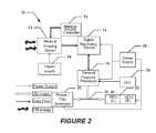
- FIG. 2a block diagram of the system 50 comprising one particular embodiment of the invention is shown.
- the diagramindicates flow of data, imagery, and the like according to the legend.
- Medical imaging device 12utilizes EM energy that emanates from the device 12 and is also received by the device 12 .
- the medical imaging device 12receives imaging commands from the controller 52 and provides imagery data to the data recording.
- the Medical device controller 52provides control commands to the medical imaging device 12 .
- a power supply 54provides power to the medical imaging device 12 .
- Digital recording device 14records each of the slices of data collected by the medical imaging device 12 , and may also be used to record medical records meta data. Digital recording device 14 interacts/exchanges data with the General purpose processor 16 .
- General purpose processor 16interacts with the digital recording device 14 based on inputs it receives from the user through the Graphical User Interface (GUI) 58 .
- GUIGraphical User Interface
- the GUI 58allows interaction between the user with the general purpose processor 16 to initiate functions such as zoom, rotate, filter tissue, and apply color schematics.
- the head display unit 22includes a left head display unit which receives an image from general purpose processor 16 and displays an image of the volume of interest as it would be seen from a left eye perspective of the user.
- the head display unitincludes a right head display unit which receives an image from general purpose processor 16 and displays image of the volume of interest as it would be seen from a right eye perspective of the user. This produces a three-dimensional image to the user 24 .
- Power supply 56supplies power to the various electronic equipment such as digital recording device 14 , general purpose processor 16 , head display unit 22 and printer/film developer 26 .
- circle 102represents a slice of image data.
- Triangles 106 and 108 extending from Left Eye Viewing Perspective (LEVP) 104represent the angles (in the X-Y plane; theta M and theta R ) from the viewpoint to the voxels within the field of view.
- Triangles 112 and 114 extending from Right Eye Viewing Perspective (REVP) 110represents the angles (in the X-Y plane; theta N and theta S ) from the viewpoint to the voxels within the field of view (FOV).
- LVPLeft Eye Viewing Perspective
- REVPRight Eye Viewing Perspective
- the viewpointsreceive light from theta (horizontal) and alpha (vertical) angles within the field of view.
- the field of viewhas a limit of 40 degrees spanning the horizontal and 30 degrees spanning the vertical.
- This bird's eye view of the diagramshows the cones as triangles. These triangles represent geometric shapes from which to gather the volumetric data and present the data in stereoscopic fashion to the head display unit (HDU).
- the circledemonstrates an axial slice through the data. Note that standard reformatted slices (i.e., coronal vs. saggital vs. oblique) may be used as the slices for the process described above.
- FIG. 3Ademonstrates the cross-section in the x-y plane at the slice at the same z-value for the LEVP and REVP. It should be noted that from the viewpoints, other viewing angles will pass through multiple slices. It should also be noted that the viewing points may be altered so that three-dimensional stereoscopic presentation may be obtained from any position and at any angle at the volumetric data.
- FIG. 3Bdepicts an embodiment wherein a user is able to adjust the convergence.
- the convergence pointis where the center theta-alpha ray from each LEVP and REVP intersect.
- the theta-alpha ray which represents the center point on the DUwill no longer be looking straight ahead (i.e., in the y-direction) and will no longer have a theta and alpha of zero degrees.
- the center pixelwill represent the theta-alpha ray from the viewing perspectives to the “C” point or convergence point as illustrated.
- This convergence pointmay be shifted to any point within (x, y, z) space at the user(s) discretion to give a different perspective of the volumetric data to the user.
- the point at which the center theta-alpha rays convergeis labeled “C.”
- Point “C”may be altered in (x, y, z) space to determine the direction of each of the alpha-theta rays. An analogy of this would be to converge your eyes to focus on an object, such as a pencil in front of you. Then the pencil is moved to a different location in (x, y, z) space. The eye muscles alter the convergence angle to view the object at the varying locations.
- a volume of interestwhich is comprised of a series of slices.
- These slicesmay be obtained from any medical imaging device view of the patient. For example, they may be obtained from an axial, saggital, coronal or any oblique view. These slices are then stacked one upon another in the sequence in which they were generated.
- the pixels in the L HDU 26 b and R HDU 26 aare shown as 152 and 154 respectively. Each pixel in the display comes form a particular theta-alpha ray (shown in FIG. 3 ).
- the span of pixels in the horizontal directionrepresents pixels from ⁇ 20 degrees (left limit in FOV) to +20 degrees (right limit in FOV). Since alpha in this example is the vertical dimension and a FOV of 30 degrees is used in this example, the span of pixels in the vertical direction represents pixels from ⁇ 15 degrees (downward limit in FOV) to +15 degrees (upper limit FOV).
- Thetais the angle from the Left Eye Viewing Perspective (LEVP) 104 to the various voxels 102 in the volumetric data set.
- the angle thetais angle in the x-y plane from the line extending exactly along the anterior-posterior direction to the LEVP to the voxels of interest in this slice. This will be the theta component for plotting a pixel based on the alpha-theta combination.
- Theta to the ‘LEVP-Left-Most-Visible-Point’is 0 degrees.
- Theta to the ‘LEVP-Right-Most-Visible-Point’is 18.4 degrees; thus, assuming the half width display of 20 deg and 612 pixels, the ‘LEVP-Right-Most-Visible-Point’ will be plotted at 559 (or 53 pixels from the right most edge of the L HDU).
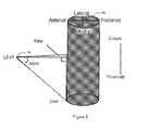
- FIG. 6shows the volumetric data in the grey cylinder.
- the angles theta and alphaare shown extending from the LEVP 104 to the voxels of interest.
- Theta and alphaare angles from the LEVP to the voxel of interest.
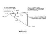
- FIG. 7illustrates hypotenuse 1 (hyp 1 ) and hypotenuse 2 (hyp 2 ).
- Hyp 2is the distance from the LEVP 104 to the voxel of interest.
- a CT scanis assumed and having a file of theta-alpha rays with associated hyp 2 s and associated Hounsfeld units for each voxel in the theta-alpha ray is helpful for generating plots such as representing the surface voxels or interior voxels in the correct pixel locations and pixel intensity on the HDU.
- a useris able to create a moving image of a volume of interest.
- Some scanstake multiple slices at the same level in sequence (i.e. cardiac-gated MRI). These type images may be viewed in true 3D stereoscopic imagery as well.
- the volumesare displayed in a 3D stereoscopic manner (as discussed in detail herein) in a consecutive manner to represent the volume of interest and how the volume of interest changes over the time sequence.
- image loopsmay be formed so when the last volume in the time interval is displayed, the process may return to the first volume displayed, then the second and so on et seq.
- the sequencemay be fast forwarded, rewound, stopped, played in slow motion, etc.
- all of the other options discussed abovemay be utilized here including rotation, zoom, convergence, etc.
- FIGS. 8-13Flow charts of the presently disclosed methods are depicted in FIGS. 8-13 .
- the rectangular elementsare herein denoted “processing blocks” and represent computer software instructions or groups of instructions.
- the processing blocksrepresent steps performed by functionally equivalent circuits such as a digital signal processor circuit or an application specific integrated circuit (ASIC).
- ASICapplication specific integrated circuit
- the flow diagramsdo not depict the syntax of any particular programming language. Rather, the flow diagrams illustrate the functional information one of ordinary skill in the art requires to fabricate circuits or to generate computer software to perform the processing required in accordance with the present invention. It should be noted that many routine program elements, such as initialization of loops and variables and the use of temporary variables are not shown.
- FIG. 8a particular embodiment of a method 400 for providing three-dimensional viewing of images by a user is shown.
- Any imaging system which can generate cross-sectionsmay be used in this process (for example, CT scans, MRIs, PETs, etc.).
- CT scansfor example, CT scans, MRIs, PETs, etc.
- embodiments of the present inventionmay be used for non-medical purposes.
- the useris afforded an opportunity to interact and direct the flow of the process. This will be done through use of a GUI.
- One optionwould be to provide pull down menus, which would ease the direction of this process.
- Method 400begins with processing block 402 which discloses selecting a volume of interest from a collection of image slices.
- viewing parameter(s)from, for example, a pull down menu.
- the userselects the zone or volume which is to be investigated.
- a sequential set of images and meta datais selected and passed to the processor.
- Meta datacould include image sequence, time, dimensions, data on imaging parameters, data on the subject and attending physician(s).
- Processing block 404states arranging the slices corresponding to the volume of interest.
- the softwarestacks slices corresponding to the area of interest.
- the processorinteracts with the stored sequential file of image slices and selects the slices which correspond to the user directed area of interest.
- the resultis a volume of interest.
- the slices stackedmay be reformatted slices in axial, saggital, coronal or oblique planes.
- the processorforms a stack of the image slices in a sequential order, which then represents the volume of interest.
- the image sliceis of a thickness that the composite stack is a contiguous volume. In the event that this is not the case, the software will interpolate between like elements (e.g., tissues) from slice to slice to create a contiguous volume.
- Processing block 406recites selecting an initial viewing angle of the slices.
- the softwarerotates the volume of interest so that the viewing angle is aligned with that directed by the user.
- the userinteracts with the GUI to indicate the initial desired viewing angle.
- the default valuewould be the front/anterior of the subject.
- One option to facilitate the processwould be for the pull down menu to illustrate a slice with an arrow depicting the viewing angle.
- Processing block 408discloses selecting a view point for a left eye
- processing block 410discloses selecting a view point for a right eye.
- the softwareselects an initial view points for left and right eyes, respectively. There would be a default value, which could be adjusted during the continuation of this process.
- the userhas the control over proximity of the viewpoints to the volume of interest.
- the pixels that make up the rows/columns in the HDUwill be assigned at this step in the process. Several methods for assignment of these pixels are feasible, one sample method for assignment is demonstrated in the detailed description.
- the presentation of these pixelsmay be in the form of transparent surfaces/volumes and non-transparent surfaces/volumes that correspond to different parts of the anatomy.
- the softwareselects the viewpoint for the left and right eyes, respectively.
- the left and the right eye viewpointswould be separated by the user interocular distance. This would provide the user with the same perspective that his/her eye-brain combination was accustomed to.
- the viewpointswould be selected at a distance from the near surface of the volume where a forty degree field of view would encompass the entire width of the volume. This would permit the user to view the entire width of the volume within the primary visual zone of the eye.
- Processingcontinues with processing block 412 which discloses displaying, in a head display unit (HDU), an image for the left eye based on the initial viewing angle, the view point for the left eye and the volume of interest and processing block 414 which states displaying, in the HDU, an image for the right eye based on the initial viewing angle, the view point for the right eye, and the volume of interest.
- the image for the left eye and the image for the right eyeproduce a three-dimensional image to the user.
- the intensity of the pixelcould be calculated.
- This pixelwould represent a cone through the volume of interest and be based on the viewing angle (theta, alpha) of that particular pixel.
- Each conewould be composed of voxels passing from each eye's respective viewpoint and tracking through the volumetric data as illustrated in the fan-shaped array in FIG. 3 .
- the number of cones in the alpha directionwill correspond to the number of pixels in the alpha direction.
- the number of cones in the theta directionwill correspond to the number of cones in the theta direction.
- a sample cone in the horizontal directionmay pass from anterior to posterior in a cross-section covering a distance of, for example, 375 mm. If each voxel were 1.25 mm in dimension, the horizontal solid consists of a line through 300 voxels. Thus, the pixel may be assigned from any single voxel or combination of the voxels's properties from which this cone passes. This particular horizontal solid would typically fall through several tissue types of varying dimensions and differing properties. Consider that each of these tissue volumes of varying types were transparent, but of different grayscales.
- An analogy at this pointwould be a cylindrical glass container filled with a clear liquid with transparent light gray spheres suspended in the liquid. Depending on which set of light gray transparent spheres one was looking through, one would get a corresponding grayscale for a pixel (theta, alpha). In a similar manner, depending on which types of tissue were contained in this horizontal volume, a corresponding grayscale would be selected. The user would see these spheres arrayed in three dimensions and thus obtain a clear understanding of the anatomy of the subject.
- Processing block 416discloses selecting images for future reference.
- the image slices generated through the imaging processare stored in a sequential file in the digital recording unit together with associated meta data.
- the methodincludes performing imaging to obtain image slices and storing the image slices as a collection of image slices. This would be done prior to the step of selecting a volume of interest from a collection of image slices.
- the processutilizes previously stored images from any variety of sources, whereas in an alternate embodiment the process includes performing the imaging and storing the images prior to the step of selecting a volume of interest.
- the useris afforded control over options designed to enhance the viewing process.
- optionsresult from a combination and sequencing of steps to include: rotating the image, selectively filtering out items (e.g., tissues), adding a color schematic, and zooming in or out.
- Method 450begins with processing block 452 which discloses the user selecting an alternative viewing angle. This step allows the user the flexibility to view the volume of interest from different angles including from any viewpoints in (x, y, z) space.
- One option for the usercould include an automatic rotation of the volume of interest with the freeze option at viewer discretion.
- Processing block 454states reorienting the volume of interest in accordance with the alternate viewing angle.
- Softwarerotates the volume to the desired viewing angle.
- the new left and right viewpointsare calculated in the manner as described above. After viewing the volume of interest from this new viewing angle, the user could select subsequent viewing angles and iterate this viewing process multiple times. For any of the particular left or right images that are of interest, the user could save the viewing perspectives for future reference.
- Processing block 456recites displaying, in the HDU, an image for the left eye based on the alternate viewing angle, the view point for the left eye and the volume of interest.
- Processing block 458discloses displaying, in the HDU, an image for the right eye based on the alternate viewing angle, the view point for the right eye, and the volume of interest and wherein the image for the left eye and the image for the right eye produce an alternate three-dimensional image to the user.
- Method 500begins with processing block 502 which recites selecting items of the image to be subtracted from the image to produce a filtered image.
- the userselects the tissues to be filtered.
- Several filtering processesare possible, including by composition (e.g. Houndsfeld unit or signal intensity) or position (x, y, z) of the tissue.
- Processing block 504discloses displaying, in the HDU, a filtered image for the left eye based on the initial viewing angle, the view point for the left eye and the volume of interest.
- Processing block 506states displaying, in the HDU, a filtered image for the right eye based on the initial viewing angle, the view point for the right eye, and the volume of interest and wherein the filtered image for the left eye and the filtered image for the right eye produce a filtered three-dimensional image to the user.
- the usercould select additional tissues for removal (or to be re-added) and iterate this process multiple times. For any of the particular left or right images that are of interest, the user could save the images for future reference.
- FIG. 11depicts a flow diagram of a particular embodiment of a method 550 for selecting items of the image to be colored.
- Method 550begins with processing block 552 which discloses sorting voxels of the items by a property of the voxel.
- processing block 552discloses sorting voxels of the items by a property of the voxel.
- An examplecould be that cortical bone would be white, blood vessels red, and brain matter gray to align with normal anatomical colors. This may be performed based on Houndsfeld units for CT, signal intensity for MRI, echogenicity of Ultrasound, etc.
- Processing block 554states applying colors to groups of sorted voxels to obtain a colored image. This would nominally be done based on the properties of the various types of tissue and the type of imaging being performed.
- Processing block 556recites displaying, in the HDU, a colored image for the left eye based on the initial viewing angle, the view point for the left eye and the volume of interest.
- Processing block 558discloses displaying, in the HDU, a colored image for the right eye based on the initial viewing angle, the view point for the right eye, and the volume of interest and wherein the colored image for the left eye and the colored image for the right eye produce a colored three-dimensional image to the user.
- the usermay choose a color schematic to help visualize the anatomy.
- Each voxelis assigned a grayscale and a subsequent histogram summation operation performed.
- the usercould again look at an image slice and click on a portion of interest and relate that to a particular bar in the histogram. This process could be repeated multiple times.
- the usercould assign the color schematic with particular colors being associated with particular bars in the histogram/tissue types within the volume.
- the softwareassigns colors as designated by the user to the voxels within the volume.
- the resultant left and right imageswould then be presented on the respective HDU.
- the pixel colorwould be again analogous to the transparent spheres immersed in the liquid as described above. Small tissue anomalies would tend to stand out depending on the color schemes chosen, thus facilitating the user's rapid detection of these anomalies.
- the usercould modify his selection and then iterate this process multiple times. For any of the particular left or right images that are of interest, the user could save the images for future reference.
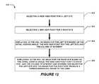
- Method 600begins with processing block 602 which recites selecting a new viewpoint for a left eye and processing block 604 which recites selecting a new viewpoint for a right eye.
- processing block 602which recites selecting a new viewpoint for a left eye
- processing block 604which recites selecting a new viewpoint for a right eye.
- the usercan alter the distance between the left and right viewing angles as well as the distance between the viewpoints and the volumetric data being viewed.
- electronic enlargement of a particular portion of the volume of interestis possible.
- Processing block 606discloses displaying, in the HDU, an image for the left eye based on the initial viewing angle, the new viewpoint for the left eye and the volume of interest.
- Processing block 608states displaying, in the HDU, an image for the right eye based on the initial viewing angle, the new view point for the right eye, and the volume of interest and wherein the image for the left eye and the image for the right eye produce a three-dimensional image to the user.
- the usermay choose to zoom into the image for an enlarged view of a particular zone of interest. There are multiple ways that this can be indicated. For example, the user could click on the pull down menu and indicate a 2 X zoom and then move the cursor to the region of interest and click on that portion which would be the area to be zoomed on.
- zoom functioncan be accomplished.
- One wayis a straightforward electronic zoom in which pixels are replicated in both the x and y directions. The net effect is that the area of interest is proportionally larger but some of the volume may no longer visible on the HDU. New information content is not available to the user with this type of zoom, however, the area of interest is enlarged which can be of some utility to the user.
- Another type of zoomwould be associated with providing greater resolution surrounding the identified zone of interest. This type of condition might prevail where the image sent to the display under samples the data that is available through the particular imaging modality.
- a novel way to zoomwould be to move the viewpoints closer to the volume of interest, thus reducing the totality of the volume observed, but enlarging the area that is actually being observed. This method would be accomplished by altering the absolute distance and points in x, y, z space between where the left eye viewpoint pixels and right eye viewpoint pixels are assigned.
- the resultant left and right imageswould then be presented on the respective HDU.
- the usercould modify his zooming selection and then iterate this process multiple times. For any of the particular left or right images that are of interest, the user could save the images for future reference.
- the usercould review which of the saved images that after completion of this process, feels worthy to flag for consultation with other members of the medical staff. This could be facilitated with the addition of additional HDUs so that all person(s) could be viewing the same image at the same time. This could, in fact, be extended via a wireless link to the HDU. These images would then be stored in the digital recording device and meta data would be available regarding these images.
- Method 650starts with processing block 652 which discloses stacking a set of images taken within a given time interval to form a volume of interest. Some scans take multiple slices at the same level in sequence (i.e. cardiac-gated MRI). For each time interval, a unique volume is generated.
- Processing block 654states displaying, in a three dimensional stereoscopic manner, said set of images of said volume of interest in a consecutive manner to represent said volume of interest and how said volume of interest changes over time.
- Processing block 656recites forming a loop of said images such that after a last image of set of images is displayed, the set of images are displayed again from the beginning image to the last image.
- the sequencemay be fast forwarded, rewound, stopped, played in slow motion, etc. Meanwhile, all of the other options discussed above may be utilized here including rotation, zoom, convergence, etc.
- H. unitsHounsfeld units
- a first stepis to establish the axes for the volumetric data.
- CT data axesmay be defined wherein in the X-direction (positive) is lateral to medial (i.e. left to right), the Y-direction (positive) is anterior to posterior (i.e. front to back), and the Z-direction (positive) is proximal to distal (i.e. elbow-end to finger-end).
- multiple coordinate systemsmay be used.
- the Cartesian coordinate system (x, y, z)is used in this example. Alternatively, spherical systems, cylindrical coordinate systems of other coordinate systems may be used for this process.
- HUD axeswherein height (positive) is bottom to top and width (positive) is left to right.
- x, y, z coordinate with associated H. uniti.e. for the data in this example, it is of the left wrist
- zthe max number of cross-sections.
- xthe max pixels in that direction.
- ythe anterior most aspect of the data (i.e. side nearest to the face)
- ythe posterior most aspect of the data (i.e.
- x-direction voxel sizeis 0.25 mm/voxel (200 pixels over 50 mm)
- y-direction voxel sizeis 0.25 mm/voxel (100 pixels over 25 mm)
- z-direction voxel sizeis 0.5 mm/voxel (150 slices over 75 mm).
- a volume with every point in the data representing a small volume (i.e. a voxel) with an associated H. unithas been produced.
- the original datais z-slices with pixels in the x, y plane
- the new datais volumetric data voxels each with inherent size and (x, y, z) coordinate with the associated Hounsfeld unit.
- the next stepinvolves establishing the Left Eye Viewing Point (LEVP) and the Right Eye Viewing Point (REVP).
- the midpoint between the user's eyesis approximately 15 cm in front of the midpoint of the anterior aspect of the wrist (with half of the data distally towards the user's fingers and half of the data proximally towards the user's elbow).
- the LEVP (x, y, z)is (0, ⁇ 150, Zmax/2) and, the REVP (x, y, z) is (50, ⁇ 150, Zmax/2).
- the portion being viewedwould not equal the interocular distance, so there would be a variation of the x-coordinates for the LEVP and REVP.
- the ‘L-HDU-Left-Most-Visible-Pt’is at the exact midpoint of the L HDU (note that this is not usually the case, but happened only because the measurement of the wrist in this orientation equaled the interocular distance).
- the right most portion of the wrist that is visible at half way up on the Z-axisis (Xmax, Ymax/2, Zmax/2) (aka L-HDU-Right-Most-Visible-pt′).
- the angle between ‘L-HDU-Left-Most-Visible-Pt’ and ‘L-HDU-Right-Most-Visible-pt’is theta.
- FOVthe display instantaneous FOV
- angle from the ‘L-HDU-Left-Most-Visible-pt’ to the right side of the HDUwould be 20 degrees.
- thetaequals 18.4 degrees
- the right most pointwould fit in the HDU (assuming a half display width of 20 degrees).
- the ‘L-HDU-Left-Most-Visible-Pt’is at (Width/2, height/2) because theta and alpha are equal to 0.
- the surface pixels of the bonesare to be displayed.
- one methodwould be to ignore all voxels with H. units less than 500 and display all voxels with H. unit of greater than 500.
- Xminis 5 mm and Xmax is 20 mm.
- xminis 30 mm and xmax is 45 mm.
- a series of thetasare computed. The first theta represents the angle off the center to the left edge of the radius.
- tan(theta)5/150. Based on that angle, one could plot the left most point of the radius bone at Zmax/2 on the L HDU at an angle calculated as theta in the above steps. This process is continued for the right most portion of the radial bone and the left and right most portion of the ulna. If assuming contiguous bone in between these points, all H.units between these points should be greater than the 500 cut-off and the result would be two contiguous white horizontal lines on the center of the L HDU.
- the next step in this exampleis it to figure out how to plot the front center point of the radius bone at Zmin.
- the LEVPis (0, ⁇ 150, Zmax/2).
- tan (theta)13/150.
- a coordinate system(may be spherical, cylindrical, Cartesian, etc.) is established.
- coordinate systemsare converted to voxels with units in volume with assoc H. unit.
- LEVP and REVPare established.
- theta and alphaare calculated and translated to respective HDUs. May use hyp 2 's (or angle to voxel of interest on other coordinate systems with distance from LEVP to voxel of interest) to determine which voxel's intensity to place in pixel alpha-theta in the HDU.
- This process for generating LEVP and REVP to attain stereoscopic visionmay be applied to cross-sectional imagery which is gathered over a cardiac cycle. In these types of imagery, multiple slices of the same level are gathered during a single cardiac cycle. This process of generating the LEVP and REVP could be applied to these types of data to generate stereoscopic perspective on the image data as it varies over the cardiac cycle.
- the first methodis referred to as the histogram method.
- a grayscalemay use Hounsfeld units in CT, signal intensity in MRI, echogenicity in ultrasound . . . etc
- Thisis an intrinsic property based on the particular tissue and interaction with the imaging device being used.
- a histogrammay be formed for all like grayscales within the total volume. The histogram results would be presented to the user and the user could summon individual slice imagery.
- the usercould select on a particular portion of the slice to ascertain which of the grayscales and which of the bars of the histogram were represented by the small volume that the user has chosen. This could be repeated multiple times so that the user understood which bars of the histogram represented which tissue types. Based on this understanding, the user could select which tissues to eliminate from the observed volume.
- a second methodis referred to as the Geometric Boundary method.
- the tissue on one side of the boundarycould be selected for removal.
- Complex boundariescould be created to eliminate particular shapes at direction of the user.
- An example algorithm to determine the method to create a surface representationis shown below:
- the grayscale usedcould be either black or white (i.e. for Hounfeld unit ⁇ 500, use 0 (black) and for H. unit>500, use 1 (white)).
- the min hyp 2 swould be used to represent the surface of the bone.
- Embodiments of the inventionprovide a process for combining slices generated by medical imaging devices to create a volume of interest and then present this volume in a three-dimensional representation to a Head Display Unit (HDU) so that the Radiologist/Medical Professional (R/MP, also referred to herein as a User) can obtain a holistic view of the patient.
- HDUHead Display Unit
- R/MPRadiologist/Medical Professional
- Key image processing techniquesare applied which enable the user: to rotate and view the volume of interest from alternative viewpoints; to enable tissue subtraction to facilitate unobstructed viewing of a region of interest; to identify differing tissues with color schematics; to zoom in for optimal viewing; and to provide a moving image of a volume of interest.
- the device(s) or computer systems that integrate with the processor(s)may include, for example, a personal computer(s), workstation(s) (e.g., Sun, HP), personal digital assistant(s) (PDA(s)), handheld device(s) such as cellular telephone(s), laptop(s), handheld computer(s), or another device(s) capable of being integrated with a processor(s) that may operate as provided herein. Accordingly, the devices provided herein are not exhaustive and are provided for illustration and not limitation.
- references to “a microprocessor” and “a processor”, or “the microprocessor” and “the processor,”may be understood to include one or more microprocessors that may communicate in a stand-alone and/or a distributed environment(s), and may thus be configured to communicate via wired or wireless communications with other processors, where such one or more processor may be configured to operate on one or more processor-controlled devices that may be similar or different devices.
- Use of such “microprocessor” or “processor” terminologymay thus also be understood to include a central processing unit, an arithmetic logic unit, an application-specific integrated circuit (IC), and/or a task engine, with such examples provided for illustration and not limitation.
- references to memorymay include one or more processor-readable and accessible memory elements and/or components that may be internal to the processor-controlled device, external to the processor-controlled device, and/or may be accessed via a wired or wireless network using a variety of communications protocols, and unless otherwise specified, may be arranged to include a combination of external and internal memory devices, where such memory may be contiguous and/or partitioned based on the application.
- references to a databasemay be understood to include one or more memory associations, where such references may include commercially available database products (e.g., SQL, Informix, Oracle) and also include proprietary databases, and may also include other structures for associating memory such as links, queues, graphs, trees, with such structures provided for illustration and not limitation.
- References to a networkmay include one or more intranets and/or the Internet, as well as a virtual network. References herein to microprocessor instructions or microprocessor-executable instructions, in accordance with the above, may be understood to include programmable hardware.
- a computer usable mediumcan include a readable memory device, such as a hard drive device, a CD-ROM, a DVD-ROM, or a computer diskette, having computer readable program code segments stored thereon.
- the computer readable mediumcan also include a communications link, either optical, wired, or wireless, having program code segments carried thereon as digital or analog signals.
Landscapes
- Engineering & Computer Science (AREA)
- Physics & Mathematics (AREA)
- Multimedia (AREA)
- Signal Processing (AREA)
- General Physics & Mathematics (AREA)
- Optics & Photonics (AREA)
- Health & Medical Sciences (AREA)
- Life Sciences & Earth Sciences (AREA)
- Computer Vision & Pattern Recognition (AREA)
- Theoretical Computer Science (AREA)
- Surgery (AREA)
- Pathology (AREA)
- Molecular Biology (AREA)
- Radiology & Medical Imaging (AREA)
- Biophysics (AREA)
- Biomedical Technology (AREA)
- Heart & Thoracic Surgery (AREA)
- Medical Informatics (AREA)
- Nuclear Medicine, Radiotherapy & Molecular Imaging (AREA)
- Animal Behavior & Ethology (AREA)
- General Health & Medical Sciences (AREA)
- Public Health (AREA)
- Veterinary Medicine (AREA)
- Image Generation (AREA)
- Image Processing (AREA)
- Apparatus For Radiation Diagnosis (AREA)
Abstract
Description
Claims (18)
Priority Applications (15)
| Application Number | Priority Date | Filing Date | Title |
|---|---|---|---|
| US12/176,569US9349183B1 (en) | 2006-12-28 | 2008-07-21 | Method and apparatus for three dimensional viewing of images |
| US14/313,398US9473766B2 (en) | 2006-12-28 | 2014-06-24 | Method and apparatus for three dimensional viewing of images |
| US14/877,442US9980691B2 (en) | 2006-12-28 | 2015-10-07 | Method and apparatus for three dimensional viewing of images |
| US15/878,463US10795457B2 (en) | 2006-12-28 | 2018-01-24 | Interactive 3D cursor |
| US16/506,073US11202061B1 (en) | 2006-12-28 | 2019-07-09 | Illustrating direction of blood flow via pointers |
| US17/021,548US10936090B2 (en) | 2006-12-28 | 2020-09-15 | Interactive 3D cursor for use in medical imaging |
| US17/095,411US10942586B1 (en) | 2006-12-28 | 2020-11-11 | Interactive 3D cursor for use in medical imaging |
| US17/122,518US11036311B2 (en) | 2006-12-28 | 2020-12-15 | Method and apparatus for 3D viewing of images on a head display unit |
| US17/122,549US11016579B2 (en) | 2006-12-28 | 2020-12-15 | Method and apparatus for 3D viewing of images on a head display unit |
| US17/339,341US11520415B2 (en) | 2006-12-28 | 2021-06-04 | Interactive 3D cursor for use in medical imaging |
| US17/410,403US11228753B1 (en) | 2006-12-28 | 2021-09-26 | Method and apparatus for performing stereoscopic zooming on a head display unit |
| US17/459,939US11315307B1 (en) | 2006-12-28 | 2021-09-26 | Method and apparatus for performing rotating viewpoints using a head display unit |
| US17/459,011US11275242B1 (en) | 2006-12-28 | 2021-09-26 | Method and apparatus for performing stereoscopic rotation of a volume on a head display unit |
| US17/728,903US12380628B1 (en) | 2006-12-28 | 2022-04-25 | Method and apparatus for generating a colored three dimensional volume via voxel elimination and color assignment to voxel groups |
| US18/047,256US12333087B2 (en) | 2006-12-28 | 2022-10-17 | Interactive 3D cursor |
Applications Claiming Priority (3)
| Application Number | Priority Date | Filing Date | Title |
|---|---|---|---|
| US87793106P | 2006-12-28 | 2006-12-28 | |
| US11/941,578US8384771B1 (en) | 2006-12-28 | 2007-11-16 | Method and apparatus for three dimensional viewing of images |
| US12/176,569US9349183B1 (en) | 2006-12-28 | 2008-07-21 | Method and apparatus for three dimensional viewing of images |
Related Parent Applications (1)
| Application Number | Title | Priority Date | Filing Date |
|---|---|---|---|
| US11/941,578Continuation-In-PartUS8384771B1 (en) | 2006-12-28 | 2007-11-16 | Method and apparatus for three dimensional viewing of images |
Related Child Applications (2)
| Application Number | Title | Priority Date | Filing Date |
|---|---|---|---|
| US14/313,398Continuation-In-PartUS9473766B2 (en) | 2006-12-28 | 2014-06-24 | Method and apparatus for three dimensional viewing of images |
| US14/877,442Continuation-In-PartUS9980691B2 (en) | 2006-12-28 | 2015-10-07 | Method and apparatus for three dimensional viewing of images |
Publications (1)
| Publication Number | Publication Date |
|---|---|
| US9349183B1true US9349183B1 (en) | 2016-05-24 |
Family
ID=55969749
Family Applications (1)
| Application Number | Title | Priority Date | Filing Date |
|---|---|---|---|
| US12/176,569Active2031-07-13US9349183B1 (en) | 2006-12-28 | 2008-07-21 | Method and apparatus for three dimensional viewing of images |
Country Status (1)
| Country | Link |
|---|---|
| US (1) | US9349183B1 (en) |
Cited By (16)
| Publication number | Priority date | Publication date | Assignee | Title |
|---|---|---|---|---|
| US20160150226A1 (en)* | 2013-06-28 | 2016-05-26 | Thomson Licensing | Multi-view three-dimensional display system and method with position sensing and adaptive number of views |
| CN107505713A (en)* | 2017-08-14 | 2017-12-22 | 友达光电股份有限公司 | Display apparatus and display method |
| US20190066390A1 (en)* | 2017-08-30 | 2019-02-28 | Dermagenesis Llc | Methods of Using an Imaging Apparatus in Augmented Reality, in Medical Imaging and Nonmedical Imaging |
| US10431004B2 (en)* | 2014-01-06 | 2019-10-01 | Samsung Electronics Co., Ltd. | Electronic device and method for displaying event in virtual reality mode |
| US10795457B2 (en) | 2006-12-28 | 2020-10-06 | D3D Technologies, Inc. | Interactive 3D cursor |
| US10846911B1 (en)* | 2019-07-09 | 2020-11-24 | Robert Edwin Douglas | 3D imaging of virtual fluids and virtual sounds |
| US10893844B1 (en)* | 2018-10-10 | 2021-01-19 | David Byron Douglas | Method and apparatus for performing 3D imaging examinations of a structure under differing configurations and analyzing morphologic changes |
| US11090873B1 (en)* | 2020-02-02 | 2021-08-17 | Robert Edwin Douglas | Optimizing analysis of a 3D printed object through integration of geo-registered virtual objects |
| US11158045B2 (en) | 2018-10-10 | 2021-10-26 | David Byron Douglas | Method and apparatus for performing 3D imaging examinations of a structure under differing configurations and analyzing morphologic changes |
| US11183296B1 (en) | 2018-02-09 | 2021-11-23 | Robert Edwin Douglas | Method and apparatus for simulated contrast for CT and MRI examinations |
| US11228753B1 (en)* | 2006-12-28 | 2022-01-18 | Robert Edwin Douglas | Method and apparatus for performing stereoscopic zooming on a head display unit |
| US11275242B1 (en)* | 2006-12-28 | 2022-03-15 | Tipping Point Medical Images, Llc | Method and apparatus for performing stereoscopic rotation of a volume on a head display unit |
| US11315307B1 (en) | 2006-12-28 | 2022-04-26 | Tipping Point Medical Images, Llc | Method and apparatus for performing rotating viewpoints using a head display unit |
| US11417071B1 (en) | 2018-02-23 | 2022-08-16 | Red Pacs, Llc | Virtual toolkit for radiologists |
| US11442534B1 (en) | 2018-04-10 | 2022-09-13 | Red Pacs, Llc | Smart glasses system |
| US11903650B2 (en) | 2019-09-11 | 2024-02-20 | Ardeshir Rastinehad | Method for providing clinical support for surgical guidance during robotic surgery |
Citations (65)
| Publication number | Priority date | Publication date | Assignee | Title |
|---|---|---|---|---|
| US4472737A (en)* | 1982-08-31 | 1984-09-18 | Tokyo Shibaura Denki Kabushiki Kaisha | Stereographic tomogram observing apparatus |
| US5049987A (en)* | 1989-10-11 | 1991-09-17 | Reuben Hoppenstein | Method and apparatus for creating three-dimensional television or other multi-dimensional images |
| US5233458A (en)* | 1991-07-01 | 1993-08-03 | Kaiser Aerospace And Electronics Corporation | Method and apparatus to reduce binocular rivalry in a partial overlap binocular display |
| US5682437A (en)* | 1994-09-22 | 1997-10-28 | Sanyo Electric Co., Ltd. | Method of converting two-dimensional images into three-dimensional images |
| US6034716A (en)* | 1997-12-18 | 2000-03-07 | Whiting; Joshua B. | Panoramic digital camera system |
| US6108005A (en)* | 1996-08-30 | 2000-08-22 | Space Corporation | Method for producing a synthesized stereoscopic image |
| US6115449A (en)* | 1998-10-10 | 2000-09-05 | Nanotek Instruments, Inc. | Apparatus for quantitative stereoscopic radiography |
| US6124977A (en)* | 1997-11-12 | 2000-09-26 | Olympus Optical Co., Ltd. | Image display apparatus |
| US20020101658A1 (en)* | 2001-01-29 | 2002-08-01 | Reuben Hoppenstein | Electronic virtual lens for observing 3-D or 4-D images |
| US6476607B1 (en)* | 2000-12-08 | 2002-11-05 | Koninklijke Philips Electronics N.V. | MRI method and apparatus for rapid acquisition of multiple views through a volume |
| US20030026474A1 (en)* | 2001-07-31 | 2003-02-06 | Kotaro Yano | Stereoscopic image forming apparatus, stereoscopic image forming method, stereoscopic image forming system and stereoscopic image forming program |
| US6532008B1 (en)* | 2000-03-13 | 2003-03-11 | Recherches Point Lab Inc. | Method and apparatus for eliminating steroscopic cross images |
| US20030107644A1 (en)* | 2000-05-09 | 2003-06-12 | Boo-Jin Choi | Movie camera and photographing method for obtaining three-dimenstional image |
| US20030194119A1 (en)* | 2002-04-15 | 2003-10-16 | General Electric Company | Semi-automatic segmentation algorithm for pet oncology images |
| US20030218720A1 (en)* | 2002-02-07 | 2003-11-27 | Olympus Optical Co., Ltd. | Three-dimensional observation apparatus and method of three-dimensional observation |
| US20040223636A1 (en)* | 1999-11-19 | 2004-11-11 | Edic Peter Michael | Feature quantification from multidimensional image data |
| US20040254454A1 (en)* | 2001-06-13 | 2004-12-16 | Kockro Ralf Alfons | Guide system and a probe therefor |
| US6862364B1 (en)* | 1999-10-27 | 2005-03-01 | Canon Kabushiki Kaisha | Stereo image processing for radiography |
| US20050096530A1 (en)* | 2003-10-29 | 2005-05-05 | Confirma, Inc. | Apparatus and method for customized report viewer |
| US20050148848A1 (en)* | 2003-11-03 | 2005-07-07 | Bracco Imaging, S.P.A. | Stereo display of tube-like structures and improved techniques therefor ("stereo display") |
| US20050244050A1 (en)* | 2002-04-25 | 2005-11-03 | Toshio Nomura | Image data creation device, image data reproduction device, and image data recording medium |
| US20050278408A1 (en)* | 2004-05-25 | 2005-12-15 | Ziosoft, Inc. | Image processing system for volume rendering |
| US20060013472A1 (en)* | 2003-10-02 | 2006-01-19 | Kenji Kagitani | Image processing apparatus and image processing method |
| US20060077204A1 (en)* | 2004-10-08 | 2006-04-13 | Hanspeter Pfister | Sample rate adaptive filtering for volume rendering |
| US20060171028A1 (en)* | 2005-01-28 | 2006-08-03 | Hitachi Displays, Ltd. | Device and method for display capable of stereoscopic vision |
| US20060177133A1 (en)* | 2004-11-27 | 2006-08-10 | Bracco Imaging, S.P.A. | Systems and methods for segmentation of volumetric objects by contour definition using a 2D interface integrated within a 3D virtual environment ("integrated contour editor") |
| US20060210111A1 (en)* | 2005-03-16 | 2006-09-21 | Dixon Cleveland | Systems and methods for eye-operated three-dimensional object location |
| US20060268104A1 (en)* | 2005-05-26 | 2006-11-30 | Real D | Ghost-compensation for improved stereoscopic projection |
| US20070058249A1 (en)* | 2005-09-09 | 2007-03-15 | Kenji Hirose | Medical stereo observation system |
| US20070147671A1 (en)* | 2005-12-22 | 2007-06-28 | Eastman Kodak Company | Analyzing radiological image using 3D stereo pairs |
| EP1843296A1 (en)* | 2006-04-06 | 2007-10-10 | Siemens Aktiengesellschaft | Method for reproducible creation of views of tomographic image data |
| US20080025584A1 (en)* | 2006-07-28 | 2008-01-31 | Varian Medical Systems Technologies, Inc. | Anatomic orientation in medical images |
| US20080055305A1 (en)* | 2006-08-31 | 2008-03-06 | Kent State University | System and methods for multi-dimensional rendering and display of full volumetric data sets |
| US20080117233A1 (en)* | 2005-01-26 | 2008-05-22 | Jonathan Mather | Multiple-Viewer Multiple-View Display And Display Controller |
| US20090034684A1 (en)* | 2007-08-02 | 2009-02-05 | Sylvain Bernard | Method and system for displaying tomosynthesis images |
| US20090051685A1 (en)* | 2007-08-21 | 2009-02-26 | Ayako Takagi | Stereoscopic image display apparatus |
| US20090219283A1 (en)* | 2008-02-29 | 2009-09-03 | Disney Enterprises, Inc. | Non-linear depth rendering of stereoscopic animated images |
| US20090232275A1 (en)* | 2008-03-13 | 2009-09-17 | Oy Ajat, Ltd. | Single sensor multi-functional dental extra-oral x-ray imaging system and method |
| US20100194861A1 (en)* | 2009-01-30 | 2010-08-05 | Reuben Hoppenstein | Advance in Transmission and Display of Multi-Dimensional Images for Digital Monitors and Television Receivers using a virtual lens |
| US20100201785A1 (en)* | 2001-11-07 | 2010-08-12 | Maria Lantin | Method and system for displaying stereoscopic detail-in-context presentations |
| US20100246911A1 (en)* | 2009-03-31 | 2010-09-30 | General Electric Company | Methods and systems for displaying quantitative segmental data in 4d rendering |
| US7822265B2 (en)* | 2004-04-14 | 2010-10-26 | Koninklijke Philips Electronics N.V. | Ghost artifact reduction for rendering 2.5D graphics |
| US7840047B2 (en)* | 2006-04-06 | 2010-11-23 | Siemens Aktiengesellschaft | Method for reproducibly generating views of tomographic image data |
| US20110026808A1 (en)* | 2009-07-06 | 2011-02-03 | Samsung Electronics Co., Ltd. | Apparatus, method and computer-readable medium generating depth map |
| US20110107270A1 (en)* | 2009-10-30 | 2011-05-05 | Bai Wang | Treatment planning in a virtual environment |
| US20110109620A1 (en)* | 2009-11-12 | 2011-05-12 | Samsung Electronics Co., Ltd. | Image processing apparatus and method for enhancing depth perception |
| US20110194728A1 (en)* | 2010-02-08 | 2011-08-11 | Chris Scott Kutcka | Method and system for forensic marking of stereoscopic 3D content media |
| US20110273543A1 (en)* | 2009-01-21 | 2011-11-10 | Nikon Corporation | Image processing apparatus, image processing method, recording method, and recording medium |
| US20120008734A1 (en)* | 2010-06-08 | 2012-01-12 | Accuray, Inc. | Target Tracking for Image-Guided Radiation Treatment |
| US20120038631A1 (en)* | 2009-01-21 | 2012-02-16 | Christopher A Mayhew | System and method for three-dimensional visualization of geographical data |
| US20120056998A1 (en)* | 2010-09-08 | 2012-03-08 | Lg Electronics Inc. | Mobile terminal and controlling method thereof |
| US20120120207A1 (en)* | 2009-12-28 | 2012-05-17 | Hiroaki Shimazaki | Image playback device and display device |
| US20120162219A1 (en)* | 2010-12-27 | 2012-06-28 | Takahiro Kobayashi | Display device and video viewing system |
| US20120190967A1 (en)* | 2010-12-23 | 2012-07-26 | Werner Nahm | Arrangement and method for quantitatively determining the blood flow within blood vessels |
| US20120215218A1 (en)* | 2011-02-23 | 2012-08-23 | Lipani John D | System and Method for Electrical Stimulation of the Lumbar Vertebral Column |
| US20120224755A1 (en)* | 2011-03-02 | 2012-09-06 | Andy Wu | Single-Action Three-Dimensional Model Printing Methods |
| US20120229595A1 (en)* | 2011-03-11 | 2012-09-13 | Miller Michael L | Synthesized spatial panoramic multi-view imaging |
| US20120242569A1 (en)* | 2011-03-25 | 2012-09-27 | Sony Corporation | Display |
| US20120269424A1 (en)* | 2011-04-21 | 2012-10-25 | Masaru Ebata | Stereoscopic image generation method and stereoscopic image generation system |
| US20130003020A1 (en)* | 2011-06-30 | 2013-01-03 | Disney Enterprises, Inc. | 3d display system with rear projection screens formed of water mist or spray |
| US20130141552A1 (en)* | 2011-12-02 | 2013-06-06 | Lg Display Co., Ltd. | Polarized glasses type stereoscopic image display device and fabrication method thereof |
| US20130182085A1 (en)* | 2011-12-31 | 2013-07-18 | Resonance Technology, Inc. | Mri-compatible 3d television and display system |
| US20140065663A1 (en)* | 2012-09-06 | 2014-03-06 | Numira Biosciences, Inc. | Methods for evaluating quantifying fibrosis in lung tissue |
| US20140176685A1 (en)* | 2011-06-28 | 2014-06-26 | Hitachi Medical Corporation | Image processing method and image processing apparatus |
| US20140253698A1 (en)* | 2013-03-11 | 2014-09-11 | Allan Thomas Evans | System, apparatus, and method for enhancing stereoscopic images |
- 2008
- 2008-07-21USUS12/176,569patent/US9349183B1/enactiveActive
Patent Citations (70)
| Publication number | Priority date | Publication date | Assignee | Title |
|---|---|---|---|---|
| US4472737A (en)* | 1982-08-31 | 1984-09-18 | Tokyo Shibaura Denki Kabushiki Kaisha | Stereographic tomogram observing apparatus |
| US5049987A (en)* | 1989-10-11 | 1991-09-17 | Reuben Hoppenstein | Method and apparatus for creating three-dimensional television or other multi-dimensional images |
| US5233458A (en)* | 1991-07-01 | 1993-08-03 | Kaiser Aerospace And Electronics Corporation | Method and apparatus to reduce binocular rivalry in a partial overlap binocular display |
| US5682437A (en)* | 1994-09-22 | 1997-10-28 | Sanyo Electric Co., Ltd. | Method of converting two-dimensional images into three-dimensional images |
| US6108005A (en)* | 1996-08-30 | 2000-08-22 | Space Corporation | Method for producing a synthesized stereoscopic image |
| US6124977A (en)* | 1997-11-12 | 2000-09-26 | Olympus Optical Co., Ltd. | Image display apparatus |
| US6034716A (en)* | 1997-12-18 | 2000-03-07 | Whiting; Joshua B. | Panoramic digital camera system |
| US6115449A (en)* | 1998-10-10 | 2000-09-05 | Nanotek Instruments, Inc. | Apparatus for quantitative stereoscopic radiography |
| US6862364B1 (en)* | 1999-10-27 | 2005-03-01 | Canon Kabushiki Kaisha | Stereo image processing for radiography |
| US20040223636A1 (en)* | 1999-11-19 | 2004-11-11 | Edic Peter Michael | Feature quantification from multidimensional image data |
| US6532008B1 (en)* | 2000-03-13 | 2003-03-11 | Recherches Point Lab Inc. | Method and apparatus for eliminating steroscopic cross images |
| US20030107644A1 (en)* | 2000-05-09 | 2003-06-12 | Boo-Jin Choi | Movie camera and photographing method for obtaining three-dimenstional image |
| US6476607B1 (en)* | 2000-12-08 | 2002-11-05 | Koninklijke Philips Electronics N.V. | MRI method and apparatus for rapid acquisition of multiple views through a volume |
| US20020101658A1 (en)* | 2001-01-29 | 2002-08-01 | Reuben Hoppenstein | Electronic virtual lens for observing 3-D or 4-D images |
| US20040254454A1 (en)* | 2001-06-13 | 2004-12-16 | Kockro Ralf Alfons | Guide system and a probe therefor |
| US20030026474A1 (en)* | 2001-07-31 | 2003-02-06 | Kotaro Yano | Stereoscopic image forming apparatus, stereoscopic image forming method, stereoscopic image forming system and stereoscopic image forming program |
| US20100201785A1 (en)* | 2001-11-07 | 2010-08-12 | Maria Lantin | Method and system for displaying stereoscopic detail-in-context presentations |
| US20030218720A1 (en)* | 2002-02-07 | 2003-11-27 | Olympus Optical Co., Ltd. | Three-dimensional observation apparatus and method of three-dimensional observation |
| US20030194119A1 (en)* | 2002-04-15 | 2003-10-16 | General Electric Company | Semi-automatic segmentation algorithm for pet oncology images |
| US20050244050A1 (en)* | 2002-04-25 | 2005-11-03 | Toshio Nomura | Image data creation device, image data reproduction device, and image data recording medium |
| US20060013472A1 (en)* | 2003-10-02 | 2006-01-19 | Kenji Kagitani | Image processing apparatus and image processing method |
| US20050096530A1 (en)* | 2003-10-29 | 2005-05-05 | Confirma, Inc. | Apparatus and method for customized report viewer |
| US20050148848A1 (en)* | 2003-11-03 | 2005-07-07 | Bracco Imaging, S.P.A. | Stereo display of tube-like structures and improved techniques therefor ("stereo display") |
| US7822265B2 (en)* | 2004-04-14 | 2010-10-26 | Koninklijke Philips Electronics N.V. | Ghost artifact reduction for rendering 2.5D graphics |
| US20050278408A1 (en)* | 2004-05-25 | 2005-12-15 | Ziosoft, Inc. | Image processing system for volume rendering |
| US7647593B2 (en)* | 2004-05-25 | 2010-01-12 | Ziosoft, Inc. | Image processing system for volume rendering |
| US7298372B2 (en)* | 2004-10-08 | 2007-11-20 | Mitsubishi Electric Research Laboratories, Inc. | Sample rate adaptive filtering for volume rendering |
| US20060077204A1 (en)* | 2004-10-08 | 2006-04-13 | Hanspeter Pfister | Sample rate adaptive filtering for volume rendering |
| US20060177133A1 (en)* | 2004-11-27 | 2006-08-10 | Bracco Imaging, S.P.A. | Systems and methods for segmentation of volumetric objects by contour definition using a 2D interface integrated within a 3D virtual environment ("integrated contour editor") |
| US20080117233A1 (en)* | 2005-01-26 | 2008-05-22 | Jonathan Mather | Multiple-Viewer Multiple-View Display And Display Controller |
| US20060171028A1 (en)* | 2005-01-28 | 2006-08-03 | Hitachi Displays, Ltd. | Device and method for display capable of stereoscopic vision |
| US20060210111A1 (en)* | 2005-03-16 | 2006-09-21 | Dixon Cleveland | Systems and methods for eye-operated three-dimensional object location |
| US20060268104A1 (en)* | 2005-05-26 | 2006-11-30 | Real D | Ghost-compensation for improved stereoscopic projection |
| US20070058249A1 (en)* | 2005-09-09 | 2007-03-15 | Kenji Hirose | Medical stereo observation system |
| US20070147671A1 (en)* | 2005-12-22 | 2007-06-28 | Eastman Kodak Company | Analyzing radiological image using 3D stereo pairs |
| EP1843296A1 (en)* | 2006-04-06 | 2007-10-10 | Siemens Aktiengesellschaft | Method for reproducible creation of views of tomographic image data |
| US7840047B2 (en)* | 2006-04-06 | 2010-11-23 | Siemens Aktiengesellschaft | Method for reproducibly generating views of tomographic image data |
| US20080025584A1 (en)* | 2006-07-28 | 2008-01-31 | Varian Medical Systems Technologies, Inc. | Anatomic orientation in medical images |
| US20080055305A1 (en)* | 2006-08-31 | 2008-03-06 | Kent State University | System and methods for multi-dimensional rendering and display of full volumetric data sets |
| US20090034684A1 (en)* | 2007-08-02 | 2009-02-05 | Sylvain Bernard | Method and system for displaying tomosynthesis images |
| US20090051685A1 (en)* | 2007-08-21 | 2009-02-26 | Ayako Takagi | Stereoscopic image display apparatus |
| US20090219283A1 (en)* | 2008-02-29 | 2009-09-03 | Disney Enterprises, Inc. | Non-linear depth rendering of stereoscopic animated images |
| US8228327B2 (en)* | 2008-02-29 | 2012-07-24 | Disney Enterprises, Inc. | Non-linear depth rendering of stereoscopic animated images |
| US20090232275A1 (en)* | 2008-03-13 | 2009-09-17 | Oy Ajat, Ltd. | Single sensor multi-functional dental extra-oral x-ray imaging system and method |
| US20120038631A1 (en)* | 2009-01-21 | 2012-02-16 | Christopher A Mayhew | System and method for three-dimensional visualization of geographical data |
| US20110273543A1 (en)* | 2009-01-21 | 2011-11-10 | Nikon Corporation | Image processing apparatus, image processing method, recording method, and recording medium |
| US20100194861A1 (en)* | 2009-01-30 | 2010-08-05 | Reuben Hoppenstein | Advance in Transmission and Display of Multi-Dimensional Images for Digital Monitors and Television Receivers using a virtual lens |
| US20100246911A1 (en)* | 2009-03-31 | 2010-09-30 | General Electric Company | Methods and systems for displaying quantitative segmental data in 4d rendering |
| US20110026808A1 (en)* | 2009-07-06 | 2011-02-03 | Samsung Electronics Co., Ltd. | Apparatus, method and computer-readable medium generating depth map |
| US20110107270A1 (en)* | 2009-10-30 | 2011-05-05 | Bai Wang | Treatment planning in a virtual environment |
| US20110109620A1 (en)* | 2009-11-12 | 2011-05-12 | Samsung Electronics Co., Ltd. | Image processing apparatus and method for enhancing depth perception |
| US20120120207A1 (en)* | 2009-12-28 | 2012-05-17 | Hiroaki Shimazaki | Image playback device and display device |
| US20110194728A1 (en)* | 2010-02-08 | 2011-08-11 | Chris Scott Kutcka | Method and system for forensic marking of stereoscopic 3D content media |
| US20120008735A1 (en)* | 2010-06-08 | 2012-01-12 | Accuray, Inc. | Imaging Methods for Image-Guided Radiation Treatment |
| US20120008734A1 (en)* | 2010-06-08 | 2012-01-12 | Accuray, Inc. | Target Tracking for Image-Guided Radiation Treatment |
| US20120056998A1 (en)* | 2010-09-08 | 2012-03-08 | Lg Electronics Inc. | Mobile terminal and controlling method thereof |
| US20120190967A1 (en)* | 2010-12-23 | 2012-07-26 | Werner Nahm | Arrangement and method for quantitatively determining the blood flow within blood vessels |
| US20120162219A1 (en)* | 2010-12-27 | 2012-06-28 | Takahiro Kobayashi | Display device and video viewing system |
| US20120215218A1 (en)* | 2011-02-23 | 2012-08-23 | Lipani John D | System and Method for Electrical Stimulation of the Lumbar Vertebral Column |
| US20120224755A1 (en)* | 2011-03-02 | 2012-09-06 | Andy Wu | Single-Action Three-Dimensional Model Printing Methods |
| US20120229595A1 (en)* | 2011-03-11 | 2012-09-13 | Miller Michael L | Synthesized spatial panoramic multi-view imaging |
| US20120242569A1 (en)* | 2011-03-25 | 2012-09-27 | Sony Corporation | Display |
| US20120269424A1 (en)* | 2011-04-21 | 2012-10-25 | Masaru Ebata | Stereoscopic image generation method and stereoscopic image generation system |
| US20140176685A1 (en)* | 2011-06-28 | 2014-06-26 | Hitachi Medical Corporation | Image processing method and image processing apparatus |
| US20130003020A1 (en)* | 2011-06-30 | 2013-01-03 | Disney Enterprises, Inc. | 3d display system with rear projection screens formed of water mist or spray |
| US8567954B2 (en)* | 2011-06-30 | 2013-10-29 | Disney Enterprises, Inc. | 3D display system with rear projection screens formed of water mist or spray |
| US20130141552A1 (en)* | 2011-12-02 | 2013-06-06 | Lg Display Co., Ltd. | Polarized glasses type stereoscopic image display device and fabrication method thereof |
| US20130182085A1 (en)* | 2011-12-31 | 2013-07-18 | Resonance Technology, Inc. | Mri-compatible 3d television and display system |
| US20140065663A1 (en)* | 2012-09-06 | 2014-03-06 | Numira Biosciences, Inc. | Methods for evaluating quantifying fibrosis in lung tissue |
| US20140253698A1 (en)* | 2013-03-11 | 2014-09-11 | Allan Thomas Evans | System, apparatus, and method for enhancing stereoscopic images |
Non-Patent Citations (4)
| Title |
|---|
| Haker et al. "Nondistorting Falttening Maps and the 3D Visualization of Colon CT Images" IEEE Transactions on Medical Imaging vol. 19, No. 7, Jul. 2000 pp. 1-6.* |
| Interrante et al. "Strategies for Effectively Visualizing 3D Flow with Volume LIC" IEEE Visualization Conference (1997) pp. 1-4.* |
| Martin et al. "Stereographic Viewing of 3D Ultrasound Images: A Novelty or a Tool?" IEEE Ultrasonics Symposium (1995) pp. 1-4.* |
| Peterson et al. "Volvulus of Gastrointestinal Tract" Radiographics 209; 29 pp. 1281-1293.* |
Cited By (27)
| Publication number | Priority date | Publication date | Assignee | Title |
|---|---|---|---|---|
| US11036311B2 (en) | 2006-12-28 | 2021-06-15 | D3D Technologies, Inc. | Method and apparatus for 3D viewing of images on a head display unit |
| US11202061B1 (en)* | 2006-12-28 | 2021-12-14 | Robert Douglas | Illustrating direction of blood flow via pointers |
| US11520415B2 (en) | 2006-12-28 | 2022-12-06 | D3D Technologies, Inc. | Interactive 3D cursor for use in medical imaging |
| US11315307B1 (en) | 2006-12-28 | 2022-04-26 | Tipping Point Medical Images, Llc | Method and apparatus for performing rotating viewpoints using a head display unit |
| US12380628B1 (en)* | 2006-12-28 | 2025-08-05 | D3D Technologies, Inc. | Method and apparatus for generating a colored three dimensional volume via voxel elimination and color assignment to voxel groups |
| US11275242B1 (en)* | 2006-12-28 | 2022-03-15 | Tipping Point Medical Images, Llc | Method and apparatus for performing stereoscopic rotation of a volume on a head display unit |
| US10795457B2 (en) | 2006-12-28 | 2020-10-06 | D3D Technologies, Inc. | Interactive 3D cursor |
| US11228753B1 (en)* | 2006-12-28 | 2022-01-18 | Robert Edwin Douglas | Method and apparatus for performing stereoscopic zooming on a head display unit |
| US11016579B2 (en) | 2006-12-28 | 2021-05-25 | D3D Technologies, Inc. | Method and apparatus for 3D viewing of images on a head display unit |
| US10936090B2 (en) | 2006-12-28 | 2021-03-02 | D3D Technologies, Inc. | Interactive 3D cursor for use in medical imaging |
| US10942586B1 (en) | 2006-12-28 | 2021-03-09 | D3D Technologies, Inc. | Interactive 3D cursor for use in medical imaging |
| US20160150226A1 (en)* | 2013-06-28 | 2016-05-26 | Thomson Licensing | Multi-view three-dimensional display system and method with position sensing and adaptive number of views |
| US10431004B2 (en)* | 2014-01-06 | 2019-10-01 | Samsung Electronics Co., Ltd. | Electronic device and method for displaying event in virtual reality mode |
| CN107505713A (en)* | 2017-08-14 | 2017-12-22 | 友达光电股份有限公司 | Display apparatus and display method |
| CN107505713B (en)* | 2017-08-14 | 2019-10-18 | 友达光电股份有限公司 | Display apparatus and display method |
| US20190066390A1 (en)* | 2017-08-30 | 2019-02-28 | Dermagenesis Llc | Methods of Using an Imaging Apparatus in Augmented Reality, in Medical Imaging and Nonmedical Imaging |
| US10607420B2 (en)* | 2017-08-30 | 2020-03-31 | Dermagenesis, Llc | Methods of using an imaging apparatus in augmented reality, in medical imaging and nonmedical imaging |
| US11183296B1 (en) | 2018-02-09 | 2021-11-23 | Robert Edwin Douglas | Method and apparatus for simulated contrast for CT and MRI examinations |
| US11417071B1 (en) | 2018-02-23 | 2022-08-16 | Red Pacs, Llc | Virtual toolkit for radiologists |
| US11442534B1 (en) | 2018-04-10 | 2022-09-13 | Red Pacs, Llc | Smart glasses system |
| US10893844B1 (en)* | 2018-10-10 | 2021-01-19 | David Byron Douglas | Method and apparatus for performing 3D imaging examinations of a structure under differing configurations and analyzing morphologic changes |
| US11158045B2 (en) | 2018-10-10 | 2021-10-26 | David Byron Douglas | Method and apparatus for performing 3D imaging examinations of a structure under differing configurations and analyzing morphologic changes |
| US10846911B1 (en)* | 2019-07-09 | 2020-11-24 | Robert Edwin Douglas | 3D imaging of virtual fluids and virtual sounds |
| US11903650B2 (en) | 2019-09-11 | 2024-02-20 | Ardeshir Rastinehad | Method for providing clinical support for surgical guidance during robotic surgery |
| US11833761B1 (en)* | 2020-02-02 | 2023-12-05 | Robert Edwin Douglas | Optimizing interaction with of tangible tools with tangible objects via registration of virtual objects to tangible tools |
| US11090873B1 (en)* | 2020-02-02 | 2021-08-17 | Robert Edwin Douglas | Optimizing analysis of a 3D printed object through integration of geo-registered virtual objects |
| US11285674B1 (en)* | 2020-02-02 | 2022-03-29 | Robert Edwin Douglas | Method and apparatus for a geo-registered 3D virtual hand |
Similar Documents
| Publication | Publication Date | Title |
|---|---|---|
| US8384771B1 (en) | Method and apparatus for three dimensional viewing of images | |
| US9349183B1 (en) | Method and apparatus for three dimensional viewing of images | |
| US9980691B2 (en) | Method and apparatus for three dimensional viewing of images | |
| US9473766B2 (en) | Method and apparatus for three dimensional viewing of images | |
| US11615560B2 (en) | Left-atrial-appendage annotation using 3D images | |
| US20200348835A1 (en) | Image handling and display in x-ray mammography and tomosynthesis | |
| US9361726B2 (en) | Medical image diagnostic apparatus, medical image processing apparatus, and methods therefor | |
| Nelson et al. | Visualization of 3D ultrasound data | |
| Lorensen et al. | Enhancing reality in the operating room | |
| US9578303B2 (en) | Image processing system, image processing apparatus, and image processing method for displaying a scale on a stereoscopic display device | |
| US20090087046A1 (en) | Digital blink comparator apparatus and software and methods for operation | |
| EP2602743A2 (en) | Matching geometry generation and display of mammograms and tomosynthesis images | |
| US8659645B2 (en) | System, apparatus, and method for image display and medical image diagnosis apparatus | |
| US20160232703A1 (en) | System and method for image processing | |
| EP3654292B1 (en) | Three-dimensional ultrasound image display method | |
| Ratib | PET/CT image navigation and communication | |
| Gao et al. | 3DSRNet: 3-D spine reconstruction network using 2-D orthogonal X-ray images based on deep learning | |
| KR20160061248A (en) | Apparatus for processing medical image and method for processing medical image thereof | |
| US20040017370A1 (en) | Medical visible image generating method | |
| Abou El-Seoud et al. | An interactive mixed reality ray tracing rendering mobile application of medical data in minimally invasive surgeries | |
| CN111462314B (en) | Organ three-dimensional image reconstruction method, operation navigation method and operation auxiliary system | |
| CN108573514B (en) | Three-dimensional fusion method and device of images and computer storage medium | |
| US20230181165A1 (en) | System and methods for image fusion | |
| Wang et al. | An evaluation of using real-time volumetric display of 3D ultrasound data for intracardiac catheter manipulation tasks | |
| TWI730777B (en) | Medical image synthesis method |
Legal Events
| Date | Code | Title | Description |
|---|---|---|---|
| STCF | Information on status: patent grant | Free format text:PATENTED CASE | |
| AS | Assignment | Owner name:D3D ENTERPRISES, LLC, FLORIDA Free format text:ASSIGNMENT OF ASSIGNORS INTEREST;ASSIGNORS:DOUGLAS, DAVID BYRON;DOUGLAS, ROBERT EDWIN;SIGNING DATES FROM 20160622 TO 20160623;REEL/FRAME:039173/0425 | |
| MAFP | Maintenance fee payment | Free format text:PAYMENT OF MAINTENANCE FEE, 4TH YR, SMALL ENTITY (ORIGINAL EVENT CODE: M2551); ENTITY STATUS OF PATENT OWNER: SMALL ENTITY Year of fee payment:4 | |
| AS | Assignment | Owner name:D3D TECHNOLOGIES, INC., FLORIDA Free format text:CHANGE OF NAME;ASSIGNOR:D3D ENTERPRISES, LLC;REEL/FRAME:054058/0360 Effective date:20181009 | |
| AS | Assignment | Owner name:D3D TECHNOLOGIES, INC., FLORIDA Free format text:ASSIGNMENT OF ASSIGNORS INTEREST;ASSIGNORS:DOUGLAS, DAVID BYRON;DOUGLAS, ROBERT EDWIN;REEL/FRAME:053718/0431 Effective date:20200908 | |
| IPR | Aia trial proceeding filed before the patent and appeal board: inter partes review | Free format text:TRIAL NO: IPR2021-00648 Opponent name:MICROSOFT CORPORATION Effective date:20210323 | |
| RF | Reissue application filed | Effective date:20230324 | |
| FEPP | Fee payment procedure | Free format text:MAINTENANCE FEE REMINDER MAILED (ORIGINAL EVENT CODE: REM.); ENTITY STATUS OF PATENT OWNER: SMALL ENTITY | |
| FEPP | Fee payment procedure | Free format text:7.5 YR SURCHARGE - LATE PMT W/IN 6 MO, SMALL ENTITY (ORIGINAL EVENT CODE: M2555); ENTITY STATUS OF PATENT OWNER: SMALL ENTITY | |
| MAFP | Maintenance fee payment | Free format text:PAYMENT OF MAINTENANCE FEE, 8TH YR, SMALL ENTITY (ORIGINAL EVENT CODE: M2552); ENTITY STATUS OF PATENT OWNER: SMALL ENTITY Year of fee payment:8 | |
| IPRC | Trial and appeal board: inter partes review certificate | Kind code of ref document:K1 Free format text:INTER PARTES REVIEW CERTIFICATE; TRIAL NO. IPR2021-00648, MAR. 23, 2021 INTER PARTES REVIEW CERTIFICATE FOR PATENT 9,349,183, ISSUED MAY 24, 2016, APPL. NO. 12/176,569, JUL. 21, 2008 INTER PARTES REVIEW CERTIFICATE ISSUED JUN. 11, 2024 Effective date:20240611 |