US9346532B1 - Fill port for a balloon - Google Patents
Fill port for a balloonDownload PDFInfo
- Publication number
- US9346532B1 US9346532B1US14/546,144US201414546144AUS9346532B1US 9346532 B1US9346532 B1US 9346532B1US 201414546144 AUS201414546144 AUS 201414546144AUS 9346532 B1US9346532 B1US 9346532B1
- Authority
- US
- United States
- Prior art keywords
- balloon
- balloon envelope
- envelope
- fill port
- tendons
- Prior art date
- Legal status (The legal status is an assumption and is not a legal conclusion. Google has not performed a legal analysis and makes no representation as to the accuracy of the status listed.)
- Expired - Fee Related, expires
Links
- 238000004891communicationMethods0.000claimsabstractdescription12
- 210000002435tendonAnatomy0.000claimsdescription27
- 239000000853adhesiveSubstances0.000claimsdescription12
- 230000001070adhesive effectEffects0.000claimsdescription12
- 239000007789gasSubstances0.000description19
- 239000000463materialSubstances0.000description12
- 238000000034methodMethods0.000description9
- 238000007789sealingMethods0.000description4
- 229920001971elastomerPolymers0.000description3
- -1polyethylenePolymers0.000description3
- UFHFLCQGNIYNRP-UHFFFAOYSA-NHydrogenChemical compound[H][H]UFHFLCQGNIYNRP-UHFFFAOYSA-N0.000description2
- 239000004698PolyethyleneSubstances0.000description2
- 230000001413cellular effectEffects0.000description2
- 238000005520cutting processMethods0.000description2
- 238000005516engineering processMethods0.000description2
- 239000001307heliumSubstances0.000description2
- 229910052734heliumInorganic materials0.000description2
- SWQJXJOGLNCZEY-UHFFFAOYSA-Nhelium atomChemical compound[He]SWQJXJOGLNCZEY-UHFFFAOYSA-N0.000description2
- 239000001257hydrogenSubstances0.000description2
- 229910052739hydrogenInorganic materials0.000description2
- 238000003780insertionMethods0.000description2
- 230000037431insertionEffects0.000description2
- 229920000573polyethylenePolymers0.000description2
- 239000005437stratosphereSubstances0.000description2
- 235000000832AyoteNutrition0.000description1
- 235000009854Cucurbita moschataNutrition0.000description1
- 240000001980Cucurbita pepoSpecies0.000description1
- 235000009804Cucurbita pepo subsp pepoNutrition0.000description1
- 239000004593EpoxySubstances0.000description1
- 230000004913activationEffects0.000description1
- YACLQRRMGMJLJV-UHFFFAOYSA-NchloropreneChemical compoundClC(=C)C=CYACLQRRMGMJLJV-UHFFFAOYSA-N0.000description1
- 238000013500data storageMethods0.000description1
- 238000010586diagramMethods0.000description1
- 239000000835fiberSubstances0.000description1
- 238000007667floatingMethods0.000description1
- 239000004816latexSubstances0.000description1
- 229920000126latexPolymers0.000description1
- 238000004519manufacturing processMethods0.000description1
- 239000000203mixtureSubstances0.000description1
- 230000003287optical effectEffects0.000description1
- 229920000139polyethylene terephthalatePolymers0.000description1
- 239000005020polyethylene terephthalateSubstances0.000description1
- 238000003825pressingMethods0.000description1
- 235000015136pumpkinNutrition0.000description1
- 229920001169thermoplasticPolymers0.000description1
- 239000010409thin filmSubstances0.000description1
Images


Classifications
- B—PERFORMING OPERATIONS; TRANSPORTING
- B64—AIRCRAFT; AVIATION; COSMONAUTICS
- B64B—LIGHTER-THAN AIR AIRCRAFT
- B64B1/00—Lighter-than-air aircraft
- B64B1/58—Arrangements or construction of gas-bags; Filling arrangements
- B—PERFORMING OPERATIONS; TRANSPORTING
- B64—AIRCRAFT; AVIATION; COSMONAUTICS
- B64B—LIGHTER-THAN AIR AIRCRAFT
- B64B1/00—Lighter-than-air aircraft
- B64B1/58—Arrangements or construction of gas-bags; Filling arrangements
- B64B1/62—Controlling gas pressure, heating, cooling, or discharging gas
Definitions
- Computing devicessuch as personal computers, laptop computers, tablet computers, cellular phones, and countless types of Internet-capable devices are increasingly prevalent in numerous aspects of modem life.
- the demand for data connectivity via the Internet, cellular data networks, and other such networksis growing.
- data connectivityis still unavailable, or if available, is unreliable and/or costly. Accordingly, additional network infrastructure is desirable.
- Some systemsmay provide network access via a balloon network operating in the stratosphere. Because of the various forces experienced by these balloons during deployment and operation, there is a balancing of needs between flexibility and stability of materials.
- the balloonsmay be made of an envelope material configured in sections or lobes to create a “pumpkin” or lobed balloon. The lobes are supported by a plurality of tendons.
- the balloon envelopeBefore a balloon can be deployed, the balloon envelope must be inflated with lighter than air lift gases, such as helium, hydrogen or other types of gases.
- gasessuch as helium, hydrogen or other types of gases.
- an interfacesuch as a small fill tube, may be attached to a top plate on the balloon and coupled to a filling hose for filling the envelope with gas.
- this interfaceis often prone to leaking and the top plate can sag or can otherwise become prolapsed into the balloon, thereby possibly causing damage to the balloon envelope, if there is not sufficient pressure at the top of the balloon to support the plate's weight.
- the apparatusmay include a main body having first and second portions.
- the first portionmay have a fill port and a hollow tube portion in communication with the fill port.
- the second portionhas a surface and is insertable into a predefined opening in the balloon envelope.
- the surface of the second portionmay be configured to be attached to an inner portion of the balloon envelope when the second portion is inserted in the predefined opening.
- the apparatusfurther includes a bonding device coupled to the surface of the second portion.
- the bonding devicemay be configured to cause a portion of the surface to make contact with the inner portion of the balloon envelope in order to bond the two portions together.
- the bonding devicemay include an inflatable balloon disposed within the balloon envelope. This inflatable balloon, when inflated, may be configured to press the portion of surface of the second portion against the portion of the balloon envelope.
- An adhesivemay be disposed on the surface of the second portion to form an airtight seal between the second portion and the balloon envelope.
- the first portion of the apparatusmay be configured to receive one or more tendons for supporting the balloon envelope.
- a plurality of threadsmay be attached to the first portion. These threads may be configured to receive a fastener to secure the tendons to the balloon envelope.
- the fastenermay be a retaining nut threadably attached to the first portion.
- the second portionmay be cylindrically shaped and the first portion may be configured to receive a lift line to lift the balloon envelope.
- a cap portionmay be attached to the fill port of the value body. The cap portion may be configured to seal the fill port so as to prevent lift gas from passing through the hollow tube portion.
- a systemmay include a balloon having a balloon envelope and an apparatus for use with the balloon envelope.
- the apparatusmay include a main body having first and second portions.
- the first portionmay have a fill port and a hollow tube portion in communication with the fill port.
- the second portionhas a surface and is insertable into a predefined opening in the balloon envelope.
- the surface of the second portionmay be configured to be attached to an inner portion of the balloon envelope when the second portion is inserted in the predefined opening.
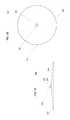
- FIG. 1is a functional diagram of a system in accordance with aspects of the present disclosure.
- FIG. 2is an example of a balloon in accordance with aspects of the present disclosure.
- FIGS. 3A-3Bare example views of an apparatus in accordance with aspects of the present disclosure.
- FIGS. 4A-4Care examples of the apparatus of FIG. 3 positioned relative to a balloon envelope in accordance with aspects of the present disclosure.
- FIGS. 5A-5Care examples of a bonding technique in accordance with aspects of the present disclosure.
- FIG. 6is another example of an apparatus in accordance with aspects of the present disclosure.
- FIG. 7is a cross-sectional view of the apparatus of FIG. 6 in accordance with aspects of the present disclosure.
- FIGS. 8A-8Care examples of an apparatus coupled to lift line in accordance with aspects of the present disclosure.
- the present disclosuregenerally relates to providing a fill port apparatus for filling balloons with lift gas.
- these balloonsmay include high altitude balloons such as those used in communication networks.
- These communication networksmay include hundreds of thousands of balloons that are deployed in the stratosphere at the same time.
- the fill port apparatusmay increase the overall efficiency in filling and readying such balloons for deployment.
- the fill port apparatusmay include a bell shaped valve body having first and second portions.
- the first portion of the valve bodymay include a hollow tube and a fill port in communication with the hollow tube.
- the second portionmay have a large cylindrically shaped surface that can be inserted into a predefined opening in a given balloon envelope.
- the surface of the valve bodymay provide the fill port apparatus with a contact area for attaching to the envelope material. Hence, the larger this surface is configured, the larger the contact area.
- the valve bodymay be made of certain type of flexible material, such as a continuous thermoplastic polymer.
- the fill port apparatusmay also include a sealing device coupled to the surface of the valve body.
- the sealing devicemay be configured to cause the surface to make contact with the balloon envelope in order to bond the two together.
- the sealing devicemay include an inflatable balloon disposed within the balloon envelope.
- An adhesivemay be disposed on the surface of the valve body. When the inflatable balloon is inflated, it may press a portion of the surface of the valve body onto a portion of the balloon envelope. In this regard, the adhesive may form a seal between the surface of the valve body and the portion of the balloon envelope when the two portions are pressed together.
- the fill port apparatusmay further include a plurality of threads attached to the fill port. These threads may be configured to receive a lifting device for lifting the balloon envelope during assembly or to receive one or more tendons for supporting the balloon envelope.
- FIG. 1depicts an example system 100 in which a balloon as described above may be used.
- system 100may be considered a “balloon network.”
- the system 100includes a plurality of devices, such as balloons 102 A-F, ground base stations 106 and 112 and links 104 , 108 , 110 and 114 that are used to facilitate intra-balloon communications as well as communications between the base stations and the balloons.
- devicessuch as balloons 102 A-F, ground base stations 106 and 112 and links 104 , 108 , 110 and 114 that are used to facilitate intra-balloon communications as well as communications between the base stations and the balloons.
- FIG. 2One example of a balloon is discussed in greater detail below with reference to FIG. 2 .
- FIG. 2is an example balloon 200 , which may represent any of the balloons of balloon network 100 .
- the balloon 200includes an envelope 210 , a payload 220 and a plurality of tendons 230 , 240 and 250 attached to the envelope 210 .
- the balloon envelope 210may take various forms.
- the balloon envelope 210may be constructed from materials such as polyethylene that do not hold much load while the balloon 200 is floating in the air during flight. Additionally, or alternatively, some or all of envelope 210 may be constructed from a highly flexible latex material or rubber material such as chloroprene. Other materials or combinations thereof may also be employed. Further, the shape and size of the envelope 210 may vary depending upon the particular implementation. Additionally, the envelope 210 may be filled with various gases or mixtures thereof, such as helium, hydrogen or any other lighter-than-air gas. The envelope 210 is thus arranged to have an associated upward buoyancy force during deployment of the payload 220 .
- the payload 220 of balloon 200may be affixed to the envelope by a connection 260 such as a cable.
- the payload 220may include a computer system (not shown), having one or more processors and on-board data storage.
- the payload 220may also include various other types of equipment and systems (not shown) to provide a number of different functions.
- the payload 220may include an optical communication system, a navigation system, a positioning system, a lighting system, an altitude control system and a power supply to supply power to various components of balloon 200 .
- balloon envelope 210In view of the goal of making the balloon envelope 210 as lightweight as possible, it may be comprised of a plurality of envelope lobes or gores that have a thin film, such as polyethylene or polyethylene terephthalate, which is lightweight, yet has suitable strength properties for use as a balloon envelope.
- balloon envelope 210is comprised of envelope gores 210 A- 210 D.
- Pressurized lift gas within the balloon envelope 210may cause a force or load to be applied to the balloon 200 .
- the tendons 230 - 250provide strength to the balloon 200 to carry the load created by the pressurized gas within the balloon envelope 210 .
- a cage of tendons(not shown) may be created using multiple tendons that are attached vertically and horizontally.
- Each tendonmay be formed as a fiber load tape that is adhered to a respective envelope gore.
- a tubular sleevemay be adhered to the respective envelopes with the tendon positioned within the tubular sleeve.
- Top ends of the tendons 230 , 240 and 250may be coupled together using an apparatus, such as top cap 201 positioned at the apex of balloon envelope 210 .
- Bottom ends of the tendons 230 , 240 and 250may also be connected to one another.
- a corresponding apparatuse.g., bottom cap 220
- the top cap 201 at the apexmay be the same size and shape as and bottom cap 220 at the bottom. Both caps include corresponding components for attaching the tendons 230 , 240 and 250 to the balloon envelope 210 .
- FIGS. 3A and 3Billustrate an example fill port apparatus 300 .
- apparatus 300may include a first portion 302 and a second portion 304 .
- the first portion 320 of apparatus 300includes a fill port 306 for inflation of the balloon envelope and a hollow tube portion 307 in communication with the fill port 306 .
- the fill port 306can be coupled to a lift gas fill source (not shown), which can be used to inflate the balloon.
- the fill port 306may allow lift gas to pass through to the hollow tube portion 307 and into an inner portion of the envelope.
- the hollow tube portion 307may thus define a flow channel for the lift gas to travel and may extend axially through the apparatus 300 in order to allow the lift gas to reach the inner portion of the envelope.
- FIG. 3Bis a top down view of the apparatus 300 .
- the second portion 304 of apparatus 300may be cylindrically shaped and have a radius that is wider than the radius of the first portion 302 .
- the shape and size of the second portion 304may be configured so that the apparatus 300 can make a sufficient amount of contact with the balloon envelope 210 in order to bond the surface of the second portion 304 with a portion of the balloon envelope material.
- surface 308 of the second portion 304may make contact with a portion of the balloon envelope.
- Apparatus 300may be attached to the balloon envelope 210 during the manufacturing process of the balloon 200 .
- the second portion 304may be inserted into an opening in the balloon envelope, for example, at an apex of the balloon 200 .
- the second portion 304made be of a lightweight yet resistibly flexible material, such as type of rubber or other types similar material, which can be manipulated and return to into an original shape.
- the surface 306 of the second portion 304can be configured to attach to what will become an inner portion of the balloon envelope.
- a bonding sealmay be formed between the second portion 304 of the apparatus 300 and the balloon envelope 210 as discussed in more detail below. This seal may prevent lift gas from leaking out of the opening of the envelope.
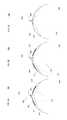
- FIGS. 4A-4Care examples 400 of apparatus 300 positioned relative to a balloon envelope 210 .
- the apparatus 300is shown at an opening 402 in the balloon envelope 210 .
- the apparatus 300is in a first unfolded shape.
- the second portion 304 when unfoldedmay have a cylindrical shape that may correspond to a shape of the opening 402 at the apex of the balloon envelope 210 .
- the opening 402 in the balloon envelope 210may be formed in several ways.
- the opening 420can be preconfigured to be included at the time the balloon envelope 210 is manufactured.
- the opening 402can be created by cutting open a portion of the balloon envelope 210 using any conventional cutting device.
- Various other techniquescan be used to create the opening 402 in the balloon envelope 210 .
- the opening 402may be sized, so that the second portion 304 of the apparatus 300 cannot pass through after being fully inserted into the balloon envelope 210 and unfolded.
- the second portion 304 of the apparatus 300is shown in a partial dashed line as this feature may be located within an interior 405 of the balloon envelope 210 .
- the second portion 304 of the apparatus 300may be inserted through opening 402 in the direction of arrow 405 .
- the second portion 304can be folded into a shape that can fit through the opening 402 .
- the second portion 304may be made of a resistibly flexible material, such as rubber, that can be manipulated then return to an original shape.
- the second portion 304is then inserted through the opening 402 and will become a part of the interior of the balloon envelope 210 when the envelope is completed.
- the second portion 304 of apparatus 300is shown completely dashed line as this portion 304 may be completely located within the interior 405 of the balloon envelope 210 .
- apparatus 300may return to the original shape.
- the second portion 304 of the apparatus 300may unfold and extend along contours of the interior 405 of balloon envelope 210 .
- surface 308 of the apparatus 300may be positioned below the opening 402 and towards a portion 406 of the interior 405 .
- this surfacemay be bonded to the interior 405 of balloon envelope 210 as discussed in more detail below.
- This bondmay be configured to create a substantially airtight seal between the second portion 304 and the balloon envelope 210 .
- the airtight sealhelps prevent lift gas from escaping from the opening 402 when balloon envelope 210 is inflated.
- FIGS. 5A-5Cillustrates one example of a bonding technique 500 , for example, to create an airtight seal between apparatus 300 and the balloon envelope 210 .
- the bonding technique 500includes using an inflatable balloon 502 attached to an inflation hose 503 and an adhesive 504 , such as type of epoxy.
- the inflatable balloon 502may be used to cause a portion of the apparatus 300 to make contact with an interior 405 of the balloon envelope 210 in order to bond the two portions together.
- the adhesive 504may be disposed on surface 308 of apparatus 300 .
- the adhesive 504may be applied to the surface 308 before or after the insertion of the second portion 304 through opening 402 .
- the inflatable balloon 502may be then inserted through the fill port of the apparatus 300 so that the inflatable balloon 502 may rest within the interior 405 of the balloon envelope 210 .
- an initial size of the inflatable balloon 502may be small enough to pass through the fill port of apparatus 300 .
- the inflatable balloon 502is shown slightly inflated.
- airmay be pumped through the inflation hose 503 at a certain rate that gradually increases the size of the inflatable balloon 502 .
- surface 308 of apparatus 300may be brought closer to an interior wall 406 of the balloon envelope 210 , thereby pressing the surface 308 of the second portion 304 against a portion of the wall.
- the inflatable balloon 502is shown even more inflated than in FIG. 5B .
- the surface 308 of the second portion 304 of apparatus 300is shown in contact with the interior wall 406 of the balloon envelope 210 .
- the adhesive 504 disposed between the two portionsmay be used form an airtight seal.
- the adhesive 504 when curedmay cause surface 308 to bond with the interior wall 406 of the balloon envelope 210 .
- the inflatable balloon 502may be deflated and retracted from the interior of the envelope 210 by using the inflation hose 503 .
- the envelope and balloonmay be completed.
- other componentse.g., tendons
- the completed balloonmay then be inflated using the apparatus as discussed above.
- the completed balloonmay be attached to a lift gas fill source via the fill port of the apparatus 300 in order to fill the envelope 210 with lift gas.
- the apparatusmay be used to help secure the other components of the balloon as discussed above in order to produce a completed balloon.
- FIG. 6is another example of an apparatus 600 for example, to be used as a fill port for a high-altitude balloon.
- Apparatus 600may be compared to the apparatus 300 of FIGS. 3A-3B and thus may be bonded to a balloon envelope using the bonding technique 500 described above.
- apparatus 600includes a first portion 602 having a fill port and hollow tube portion (not shown) and a second portion 602 that is attachable to a balloon envelope.
- the first portion 602 and second portion 604may be compared to first portion 302 and second portion 304 , respectively.
- the first portion 602includes a plurality of threads 606 .
- the threads 606may be configured to receive a cap 608 .
- the cap 608may be used to help prevent lift gas from passing through the fill port of the apparatus 600 .
- the cap 608may be attached to the threads 606 in order to help keep the fill port closed.
- FIG. 7is a cross sectional view of the apparatus 600 of FIG. 6 .
- apparatus 600may be further configured to receive one or more tendons 704 .
- the tendons 704can be looped around the first portion 602 of apparatus 600 .
- the first portion 602may be configured to extend a sufficient length outwardly from an apex of the balloon envelope in order to accommodate the tendons 704 .
- the tendons 704may provide support of supporting a load of lift gas carried by the balloon envelope.
- the first portion 602may be configured to receive a fastener 702 .
- the fastener 702may ensure that when the tendons 704 are placed at the apex they will not fall of the balloon envelope.
- Fastener 702may include one or more various different types of clips, nuts, pins or other types of hardware devices.
- the fastener 702may include a retaining nut.
- the retaining nutmay be threadably attached to the first portion 602 by using a twisting motion that may tightly secure the tendons 704 in place.
- apparatus 600may be configured to receive a lift line.
- a lifting devicesuch as a hoist
- a lifting devicemay be coupled to the apparatus 600 via the lift line in order to lift the balloon envelope during assembly.
- apparatus 810may be compared to apparatus 300 and apparatus 600 and thus may be bonded to a balloon envelope using the bonding technique 500 described above.
- apparatus 810includes a first portion 812 having a fill port and hollow tube portion (not shown) and a second portion 814 attached to balloon envelope 210 .
- First portion 812 and second portion 814may be compared to the first and second portions 302 , 304 , 602 , and 604 , respectively.
- the balloon envelope 210is shown coming out of a box 830 , such as a shipping box for the envelope 210 .
- the apparatus 810is attached to an apex of the balloon envelope 210 .
- the balloon envelopeis being pulled upward, for example, by a hoisting device (not shown) using lift line 805 .
- FIG. 8Bthe balloon envelope 210 is even higher out of the box 830 .
- FIG. 8Cshows the balloon envelope 210 at another height. For example, this may be a height high enough to accommodate the fully inflated balloon envelope 210 .
- the balloon envelope 210may be inflated and prepared for deployment.
Landscapes
- Engineering & Computer Science (AREA)
- Mechanical Engineering (AREA)
- Aviation & Aerospace Engineering (AREA)
- Toys (AREA)
Abstract
Description
Claims (20)
Priority Applications (2)
| Application Number | Priority Date | Filing Date | Title |
|---|---|---|---|
| US14/546,144US9346532B1 (en) | 2014-11-18 | 2014-11-18 | Fill port for a balloon |
| US15/137,227US9643707B1 (en) | 2014-11-18 | 2016-04-25 | Fill port for a balloon |
Applications Claiming Priority (1)
| Application Number | Priority Date | Filing Date | Title |
|---|---|---|---|
| US14/546,144US9346532B1 (en) | 2014-11-18 | 2014-11-18 | Fill port for a balloon |
Related Child Applications (1)
| Application Number | Title | Priority Date | Filing Date |
|---|---|---|---|
| US15/137,227ContinuationUS9643707B1 (en) | 2014-11-18 | 2016-04-25 | Fill port for a balloon |
Publications (1)
| Publication Number | Publication Date |
|---|---|
| US9346532B1true US9346532B1 (en) | 2016-05-24 |
Family
ID=55969584
Family Applications (2)
| Application Number | Title | Priority Date | Filing Date |
|---|---|---|---|
| US14/546,144Expired - Fee RelatedUS9346532B1 (en) | 2014-11-18 | 2014-11-18 | Fill port for a balloon |
| US15/137,227Expired - Fee RelatedUS9643707B1 (en) | 2014-11-18 | 2016-04-25 | Fill port for a balloon |
Family Applications After (1)
| Application Number | Title | Priority Date | Filing Date |
|---|---|---|---|
| US15/137,227Expired - Fee RelatedUS9643707B1 (en) | 2014-11-18 | 2016-04-25 | Fill port for a balloon |
Country Status (1)
| Country | Link |
|---|---|
| US (2) | US9346532B1 (en) |
Cited By (17)
| Publication number | Priority date | Publication date | Assignee | Title |
|---|---|---|---|---|
| US9540091B1 (en) | 2016-02-11 | 2017-01-10 | World View Enterprises Inc. | High altitude balloon systems and methods |
| US9561858B2 (en) | 2015-03-09 | 2017-02-07 | World View Enterprises Inc. | Rigidized assisted opening system for high altitude parafoils |
| US9694910B2 (en) | 2013-02-22 | 2017-07-04 | World View Enterprises Inc. | Near-space operation systems |
| US9963216B1 (en)* | 2016-02-26 | 2018-05-08 | X Development Llc | Filling apparatus for high-altitude balloons |
| US10124875B1 (en) | 2017-01-09 | 2018-11-13 | World View Enterprises Inc. | Continuous multi-chamber super pressure balloon |
| US10322789B2 (en)* | 2014-04-10 | 2019-06-18 | Loon Llc | Filling apparatus for high-altitude balloons |
| US10336432B1 (en) | 2017-01-09 | 2019-07-02 | World View Enterprises Inc. | Lighter than air balloon systems and methods |
| US11772795B1 (en)* | 2021-06-03 | 2023-10-03 | Ltag Systems, Llc | Payload deployment from aerostats |
| US11958585B1 (en) | 2020-11-25 | 2024-04-16 | Ltag Systems Llc | Midair deployment of aerostats |
| US11964748B1 (en) | 2021-01-27 | 2024-04-23 | Ltag Systems Llc | Remote generation of lifting gas |
| US20240217642A1 (en)* | 2021-04-08 | 2024-07-04 | Space Balloon Technologies Corp. | Apparatus, Method And System For Balloon Altitude Control By In-Situ Characterization And Active Energy Management |
| US12139403B1 (en) | 2019-12-08 | 2024-11-12 | Ltag Systems Llc | Storing activated aluminum |
| US12187405B1 (en) | 2019-09-08 | 2025-01-07 | Ltag Systems Llc | Controlling lifting gas in inflatable structures |
| US12275516B1 (en) | 2023-02-21 | 2025-04-15 | Ltag Systems Llc | Stabilization and reinforcement of balloons during rapid filling |
| US12296940B2 (en) | 2021-10-17 | 2025-05-13 | Ltag Systems Llc | Lifting gas generation |
| US12325504B2 (en) | 2022-11-07 | 2025-06-10 | World View Enterprises Inc. | Magnetic ballast dispenser |
| US12429311B1 (en) | 2023-02-07 | 2025-09-30 | Ltag Systems Llc | Aerostats for aerial platform acquisition |
Citations (19)
| Publication number | Priority date | Publication date | Assignee | Title |
|---|---|---|---|---|
| US4416433A (en)* | 1981-07-13 | 1983-11-22 | Bellina Joseph H | Signal balloon dispensing apparatus |
| US4586456A (en)* | 1984-06-01 | 1986-05-06 | Forward Ross M | Inflatable balloon distress marker having small article containing compartment therein |
| US6182924B1 (en)* | 1998-06-09 | 2001-02-06 | Julian Nott | Ballast for lighter than air aircraft |
| US6628941B2 (en)* | 1999-06-29 | 2003-09-30 | Space Data Corporation | Airborne constellation of communications platforms and method |
| US7275496B2 (en) | 2003-04-11 | 2007-10-02 | Ada Technology, Inc. | Balloonsonde launcher |
| US7341224B1 (en)* | 2004-10-14 | 2008-03-11 | Osann Jr Robert | Miniature expendable surveillance balloon system |
| US7344267B2 (en)* | 2004-11-12 | 2008-03-18 | Michael Schrimmer | Illuminated toy balloon |
| US7356390B2 (en)* | 1999-06-29 | 2008-04-08 | Space Data Corporation | Systems and applications of lighter-than-air (LTA) platforms |
| US7478779B2 (en)* | 2004-06-05 | 2009-01-20 | Phu Nguyen | Device and method for sealing and lighting a balloon |
| US7568656B2 (en)* | 2004-04-27 | 2009-08-04 | Handley Alan R | System for controlling the lift of aircraft |
| US20100270425A1 (en)* | 2008-09-02 | 2010-10-28 | Yonatan Zur | Apparatus and system for providing surveillance of an area or a space |
| US7934522B2 (en)* | 2006-09-07 | 2011-05-03 | Yao Sin Liao | Multi-sectional airtight seal for continuous air-filling and air valve device thereof |
| US20120312911A1 (en)* | 2011-06-13 | 2012-12-13 | Stephen Heppe | Airship launch from a cargo airship |
| US8505847B2 (en)* | 2011-03-01 | 2013-08-13 | John Ciampa | Lighter-than-air systems, methods, and kits for obtaining aerial images |
| US20140124616A1 (en) | 2012-11-02 | 2014-05-08 | Michael Alan Greco | Aerostat deployment system and methods for the same |
| US20140158823A1 (en) | 2012-12-07 | 2014-06-12 | Michael Smith | High altitude balloon system |
| US8814084B2 (en)* | 2010-05-25 | 2014-08-26 | New Create Ltd. | Controllable buoyant system and method |
| US8998128B2 (en)* | 2013-05-28 | 2015-04-07 | Google Inc. | Umbrella valves to inflate bladder in balloon envelope |
| US9027877B1 (en)* | 2014-04-10 | 2015-05-12 | Google Inc. | Filling apparatus for high-altitude balloons |
- 2014
- 2014-11-18USUS14/546,144patent/US9346532B1/ennot_activeExpired - Fee Related
- 2016
- 2016-04-25USUS15/137,227patent/US9643707B1/ennot_activeExpired - Fee Related
Patent Citations (19)
| Publication number | Priority date | Publication date | Assignee | Title |
|---|---|---|---|---|
| US4416433A (en)* | 1981-07-13 | 1983-11-22 | Bellina Joseph H | Signal balloon dispensing apparatus |
| US4586456A (en)* | 1984-06-01 | 1986-05-06 | Forward Ross M | Inflatable balloon distress marker having small article containing compartment therein |
| US6182924B1 (en)* | 1998-06-09 | 2001-02-06 | Julian Nott | Ballast for lighter than air aircraft |
| US7356390B2 (en)* | 1999-06-29 | 2008-04-08 | Space Data Corporation | Systems and applications of lighter-than-air (LTA) platforms |
| US6628941B2 (en)* | 1999-06-29 | 2003-09-30 | Space Data Corporation | Airborne constellation of communications platforms and method |
| US7275496B2 (en) | 2003-04-11 | 2007-10-02 | Ada Technology, Inc. | Balloonsonde launcher |
| US7568656B2 (en)* | 2004-04-27 | 2009-08-04 | Handley Alan R | System for controlling the lift of aircraft |
| US7478779B2 (en)* | 2004-06-05 | 2009-01-20 | Phu Nguyen | Device and method for sealing and lighting a balloon |
| US7341224B1 (en)* | 2004-10-14 | 2008-03-11 | Osann Jr Robert | Miniature expendable surveillance balloon system |
| US7344267B2 (en)* | 2004-11-12 | 2008-03-18 | Michael Schrimmer | Illuminated toy balloon |
| US7934522B2 (en)* | 2006-09-07 | 2011-05-03 | Yao Sin Liao | Multi-sectional airtight seal for continuous air-filling and air valve device thereof |
| US20100270425A1 (en)* | 2008-09-02 | 2010-10-28 | Yonatan Zur | Apparatus and system for providing surveillance of an area or a space |
| US8814084B2 (en)* | 2010-05-25 | 2014-08-26 | New Create Ltd. | Controllable buoyant system and method |
| US8505847B2 (en)* | 2011-03-01 | 2013-08-13 | John Ciampa | Lighter-than-air systems, methods, and kits for obtaining aerial images |
| US20120312911A1 (en)* | 2011-06-13 | 2012-12-13 | Stephen Heppe | Airship launch from a cargo airship |
| US20140124616A1 (en) | 2012-11-02 | 2014-05-08 | Michael Alan Greco | Aerostat deployment system and methods for the same |
| US20140158823A1 (en) | 2012-12-07 | 2014-06-12 | Michael Smith | High altitude balloon system |
| US8998128B2 (en)* | 2013-05-28 | 2015-04-07 | Google Inc. | Umbrella valves to inflate bladder in balloon envelope |
| US9027877B1 (en)* | 2014-04-10 | 2015-05-12 | Google Inc. | Filling apparatus for high-altitude balloons |
Cited By (36)
| Publication number | Priority date | Publication date | Assignee | Title |
|---|---|---|---|---|
| US11613364B2 (en) | 2013-02-22 | 2023-03-28 | World View Enterprises Inc. | Near-space operation systems |
| US9694910B2 (en) | 2013-02-22 | 2017-07-04 | World View Enterprises Inc. | Near-space operation systems |
| US12195189B2 (en) | 2013-02-22 | 2025-01-14 | World View Enterprises Inc. | Near-space operation systems |
| US10829229B2 (en) | 2013-02-22 | 2020-11-10 | World View Enterprises Inc. | Near-space operation systems |
| US10322789B2 (en)* | 2014-04-10 | 2019-06-18 | Loon Llc | Filling apparatus for high-altitude balloons |
| US9561858B2 (en) | 2015-03-09 | 2017-02-07 | World View Enterprises Inc. | Rigidized assisted opening system for high altitude parafoils |
| US11608181B2 (en) | 2015-03-09 | 2023-03-21 | World View Enterprises Inc. | Rigidized assisted opening system for high altitude parafoils |
| US10787268B2 (en) | 2015-03-09 | 2020-09-29 | World View Enterprises Inc. | Rigidized assisted opening system for high altitude parafoils |
| US10988227B2 (en) | 2016-02-11 | 2021-04-27 | World View Enterprises Inc. | High altitude balloon systems and methods using continuous multi-compartment super pressure balloon |
| US12151800B2 (en) | 2016-02-11 | 2024-11-26 | World View Enterprises Inc. | High altitude balloon systems and methods |
| US9540091B1 (en) | 2016-02-11 | 2017-01-10 | World View Enterprises Inc. | High altitude balloon systems and methods |
| US9963216B1 (en)* | 2016-02-26 | 2018-05-08 | X Development Llc | Filling apparatus for high-altitude balloons |
| US10220929B1 (en)* | 2016-02-26 | 2019-03-05 | Loon Llc | Filling apparatus for high-altitude balloons |
| US10059422B1 (en)* | 2016-02-26 | 2018-08-28 | X Development Llc | Filling apparatus for high-altitude balloons |
| US10737754B1 (en) | 2017-01-09 | 2020-08-11 | World View Enterprises Inc. | Continuous multi-chamber super pressure balloon |
| US10336432B1 (en) | 2017-01-09 | 2019-07-02 | World View Enterprises Inc. | Lighter than air balloon systems and methods |
| US11447226B1 (en) | 2017-01-09 | 2022-09-20 | World View Enterprises Inc. | Lighter than air balloon systems and methods |
| US10829192B1 (en) | 2017-01-09 | 2020-11-10 | World View Enterprises Inc. | Lighter than air balloon systems and methods |
| US12214855B2 (en) | 2017-01-09 | 2025-02-04 | World View Enterprises Inc. | Lighter than air balloon systems and methods |
| US10124875B1 (en) | 2017-01-09 | 2018-11-13 | World View Enterprises Inc. | Continuous multi-chamber super pressure balloon |
| US11904999B2 (en) | 2017-01-09 | 2024-02-20 | World View Enterprises Inc. | Lighter than air balloon systems and methods |
| US11511843B2 (en) | 2017-01-09 | 2022-11-29 | World View Enterprises Inc. | Lighter than air balloon systems and methods |
| US12187405B1 (en) | 2019-09-08 | 2025-01-07 | Ltag Systems Llc | Controlling lifting gas in inflatable structures |
| US12139403B1 (en) | 2019-12-08 | 2024-11-12 | Ltag Systems Llc | Storing activated aluminum |
| US12428124B1 (en) | 2020-11-25 | 2025-09-30 | Ltag Systems Llc | Midair deployment of aerostats |
| US11958585B1 (en) | 2020-11-25 | 2024-04-16 | Ltag Systems Llc | Midair deployment of aerostats |
| US11964748B1 (en) | 2021-01-27 | 2024-04-23 | Ltag Systems Llc | Remote generation of lifting gas |
| US12312063B2 (en)* | 2021-04-08 | 2025-05-27 | Space Balloon Technologies Corp. | Apparatus, method and system for balloon altitude control by in-situ characterization and active energy management |
| US20250249997A1 (en)* | 2021-04-08 | 2025-08-07 | Space Balloon Technologies Corp. | Apparatus, Method And System For Balloon Altitude Control By In-Situ Characterization And Active Energy Management |
| US20240217642A1 (en)* | 2021-04-08 | 2024-07-04 | Space Balloon Technologies Corp. | Apparatus, Method And System For Balloon Altitude Control By In-Situ Characterization And Active Energy Management |
| US11772795B1 (en)* | 2021-06-03 | 2023-10-03 | Ltag Systems, Llc | Payload deployment from aerostats |
| US11866196B1 (en)* | 2021-06-03 | 2024-01-09 | Ltag Systems Llc | Payload deployment from aerostats |
| US12296940B2 (en) | 2021-10-17 | 2025-05-13 | Ltag Systems Llc | Lifting gas generation |
| US12325504B2 (en) | 2022-11-07 | 2025-06-10 | World View Enterprises Inc. | Magnetic ballast dispenser |
| US12429311B1 (en) | 2023-02-07 | 2025-09-30 | Ltag Systems Llc | Aerostats for aerial platform acquisition |
| US12275516B1 (en) | 2023-02-21 | 2025-04-15 | Ltag Systems Llc | Stabilization and reinforcement of balloons during rapid filling |
Also Published As
| Publication number | Publication date |
|---|---|
| US9643707B1 (en) | 2017-05-09 |
Similar Documents
| Publication | Publication Date | Title |
|---|---|---|
| US9346532B1 (en) | Fill port for a balloon | |
| US9334037B1 (en) | Tendon mounting system | |
| US9266599B1 (en) | Apparatus to lift and fill a balloon | |
| US10696371B1 (en) | Method for sealing the apex of a balloon directly to a rigid plate | |
| US11203402B2 (en) | Envelope film suspenders for high-altitude balloons | |
| US10800506B1 (en) | Balloon launching apparatuses | |
| US9174719B1 (en) | Tendon routing at envelope apex | |
| US9643709B1 (en) | Balloon gas release flight termination system | |
| US10322789B2 (en) | Filling apparatus for high-altitude balloons | |
| US20170217736A1 (en) | Mechanical assembly for lifting a balloon | |
| US10472040B1 (en) | Sealing ducts into a balloon | |
| US9296462B1 (en) | Flight termination system for a balloon | |
| US10793246B1 (en) | Anti-tilt assembly for balloons | |
| US20210016867A1 (en) | Lighter-than-air leakage reduction | |
| US20230356825A1 (en) | Flight termination system for tethered aerial vehicles | |
| US11208191B2 (en) | Flight termination system for tethered aerial vehicles | |
| US10654574B2 (en) | Airfoil for steadying an evacuation slide | |
| US10293913B1 (en) | Termination assembly for use with balloon envelopes | |
| CN108146640A (en) | Collapsible air ejector cylinder | |
| CN105988280A (en) | Easily-foldable and unfoldable inflating and suction soft ball screen | |
| US20160376012A1 (en) | Coaxial double layer parachute | |
| CN206579863U (en) | Inflated supporting device for aerostatics |
Legal Events
| Date | Code | Title | Description |
|---|---|---|---|
| AS | Assignment | Owner name:GOOGLE INC., CALIFORNIA Free format text:ASSIGNMENT OF ASSIGNORS INTEREST;ASSIGNOR:RATNER, DANIEL;REEL/FRAME:034209/0658 Effective date:20141117 | |
| STCF | Information on status: patent grant | Free format text:PATENTED CASE | |
| AS | Assignment | Owner name:X DEVELOPMENT LLC, CALIFORNIA Free format text:ASSIGNMENT OF ASSIGNORS INTEREST;ASSIGNOR:GOOGLE INC.;REEL/FRAME:039900/0610 Effective date:20160901 | |
| AS | Assignment | Owner name:GOOGLE LLC, CALIFORNIA Free format text:CHANGE OF NAME;ASSIGNOR:GOOGLE INC.;REEL/FRAME:044144/0001 Effective date:20170929 | |
| AS | Assignment | Owner name:GOOGLE LLC, CALIFORNIA Free format text:CORRECTIVE ASSIGNMENT TO CORRECT THE CORRECTIVE BY NULLIFICATION TO CORRECT INCORRECTLY RECORDED APPLICATION NUMBERS PREVIOUSLY RECORDED ON REEL 044144 FRAME 0001. ASSIGNOR(S) HEREBY CONFIRMS THE CHANGE OF NAME;ASSIGNOR:GOOGLE INC.;REEL/FRAME:047894/0508 Effective date:20170929 | |
| AS | Assignment | Owner name:LOON LLC, CALIFORNIA Free format text:ASSIGNMENT OF ASSIGNORS INTEREST;ASSIGNOR:X DEVELOPMENT LLC;REEL/FRAME:048175/0720 Effective date:20180627 | |
| MAFP | Maintenance fee payment | Free format text:PAYMENT OF MAINTENANCE FEE, 4TH YEAR, LARGE ENTITY (ORIGINAL EVENT CODE: M1551); ENTITY STATUS OF PATENT OWNER: LARGE ENTITY Year of fee payment:4 | |
| AS | Assignment | Owner name:LOON LLC, CALIFORNIA Free format text:ASSIGNMENT OF ASSIGNORS INTEREST;ASSIGNOR:X DEVELOPMENT LLC;REEL/FRAME:052345/0094 Effective date:20180627 | |
| AS | Assignment | Owner name:AEROSTAR INTERNATIONAL, INC., MINNESOTA Free format text:ASSIGNMENT OF ASSIGNORS INTEREST;ASSIGNOR:LOON LLC;REEL/FRAME:056282/0458 Effective date:20210504 | |
| AS | Assignment | Owner name:AEROSTAR INTERNATIONAL, INC., SOUTH DAKOTA Free format text:CORRECTIVE ASSIGNMENT TO CORRECT THE STATE OF THE ASSIGNEE FROM MINNESOTA TO SOUTH DAKOTA AS PREVIOUSLY RECORDED AT REEL: 056282 FRAME: 0458. ASSIGNOR(S) HEREBY CONFIRMS THE ASSIGNMENT;ASSIGNOR:LOON LLC;REEL/FRAME:061521/0291 Effective date:20210504 | |
| AS | Assignment | Owner name:AEROSTAR INTERNATIONAL, LLC, MARYLAND Free format text:MERGER;ASSIGNOR:AEROSTAR INTERNATIONAL, INC.;REEL/FRAME:061733/0285 Effective date:20220726 | |
| FEPP | Fee payment procedure | Free format text:MAINTENANCE FEE REMINDER MAILED (ORIGINAL EVENT CODE: REM.); ENTITY STATUS OF PATENT OWNER: LARGE ENTITY | |
| AS | Assignment | Owner name:GOOGLE LLC, CALIFORNIA Free format text:CORRECTIVE ASSIGNMENT TO CORRECT THE THE REMOVAL OF THE INCORRECTLY RECORDED APPLICATION NUMBERS 14/149802 AND 15/419313 PREVIOUSLY RECORDED AT REEL: 44144 FRAME: 1. ASSIGNOR(S) HEREBY CONFIRMS THE CHANGE OF NAME;ASSIGNOR:GOOGLE INC.;REEL/FRAME:068092/0502 Effective date:20170929 | |
| STCH | Information on status: patent discontinuation | Free format text:PATENT EXPIRED DUE TO NONPAYMENT OF MAINTENANCE FEES UNDER 37 CFR 1.362 | |
| FP | Lapsed due to failure to pay maintenance fee | Effective date:20240524 |