US9345822B2 - Methods and devices for applying closed incision negative pressure wound therapy - Google Patents
Methods and devices for applying closed incision negative pressure wound therapyDownload PDFInfo
- Publication number
- US9345822B2 US9345822B2US13/779,280US201313779280AUS9345822B2US 9345822 B2US9345822 B2US 9345822B2US 201313779280 AUS201313779280 AUS 201313779280AUS 9345822 B2US9345822 B2US 9345822B2
- Authority
- US
- United States
- Prior art keywords
- sealant layer
- collection chamber
- area
- wound
- incision
- Prior art date
- Legal status (The legal status is an assumption and is not a legal conclusion. Google has not performed a legal analysis and makes no representation as to the accuracy of the status listed.)
- Active, expires
Links
- 238000000034methodMethods0.000titledescription27
- 238000009581negative-pressure wound therapyMethods0.000titledescription3
- 239000000565sealantSubstances0.000claimsabstractdescription228
- 208000014674injuryDiseases0.000claimsabstractdescription113
- 230000008733traumaEffects0.000claimsabstractdescription113
- 239000012530fluidSubstances0.000claimsabstractdescription45
- 238000004891communicationMethods0.000claimsabstractdescription43
- 206010052428WoundDiseases0.000claimsdescription130
- 208000027418Wounds and injuryDiseases0.000claimsdescription128
- 230000000670limiting effectEffects0.000claimsdescription25
- 239000000853adhesiveSubstances0.000claimsdescription18
- 230000001070adhesive effectEffects0.000claimsdescription18
- 230000008602contractionEffects0.000claimsdescription11
- 230000004044responseEffects0.000claimsdescription5
- 230000007704transitionEffects0.000claimsdescription4
- 238000002560therapeutic procedureMethods0.000abstractdescription55
- 230000002829reductive effectEffects0.000abstractdescription52
- 208000002847Surgical WoundDiseases0.000abstractdescription30
- 239000000463materialSubstances0.000abstractdescription29
- 230000003247decreasing effectEffects0.000abstract1
- 239000010410layerSubstances0.000description274
- 210000003491skinAnatomy0.000description131
- 210000001519tissueAnatomy0.000description29
- 239000011241protective layerSubstances0.000description25
- 230000035882stressEffects0.000description25
- 230000007246mechanismEffects0.000description19
- 238000007789sealingMethods0.000description12
- 230000009977dual effectEffects0.000description11
- 230000035876healingEffects0.000description11
- 239000003795chemical substances by applicationSubstances0.000description10
- 230000000295complement effectEffects0.000description8
- 230000033001locomotionEffects0.000description8
- 230000006835compressionEffects0.000description7
- 238000007906compressionMethods0.000description7
- 239000006260foamSubstances0.000description7
- 238000000926separation methodMethods0.000description7
- 206010048038Wound infectionDiseases0.000description6
- 230000008878couplingEffects0.000description6
- 238000010168coupling processMethods0.000description6
- 238000005859coupling reactionMethods0.000description6
- 238000005520cutting processMethods0.000description6
- 210000000416exudates and transudateAnatomy0.000description6
- 230000001105regulatory effectEffects0.000description6
- 239000003242anti bacterial agentSubstances0.000description5
- 229940088710antibiotic agentDrugs0.000description5
- 239000004599antimicrobialSubstances0.000description5
- 238000006073displacement reactionMethods0.000description5
- 230000002745absorbentEffects0.000description4
- 239000002250absorbentSubstances0.000description4
- 238000009826distributionMethods0.000description4
- 230000000007visual effectEffects0.000description4
- 239000011324beadSubstances0.000description3
- 230000015572biosynthetic processEffects0.000description3
- 239000011248coating agentSubstances0.000description3
- 238000000576coating methodMethods0.000description3
- 229940124447delivery agentDrugs0.000description3
- 230000000694effectsEffects0.000description3
- 239000003292glueSubstances0.000description3
- 239000000416hydrocolloidSubstances0.000description3
- 208000015181infectious diseaseDiseases0.000description3
- 230000036961partial effectEffects0.000description3
- 230000009467reductionEffects0.000description3
- 230000037390scarringEffects0.000description3
- 238000004513sizingMethods0.000description3
- 230000003068static effectEffects0.000description3
- 230000029663wound healingEffects0.000description3
- 241000894006BacteriaSpecies0.000description2
- GHXZTYHSJHQHIJ-UHFFFAOYSA-NChlorhexidineChemical compoundC=1C=C(Cl)C=CC=1NC(N)=NC(N)=NCCCCCCN=C(N)N=C(N)NC1=CC=C(Cl)C=C1GHXZTYHSJHQHIJ-UHFFFAOYSA-N0.000description2
- 208000034693LacerationDiseases0.000description2
- 206010030113OedemaDiseases0.000description2
- 230000003213activating effectEffects0.000description2
- 230000008859changeEffects0.000description2
- 229960003260chlorhexidineDrugs0.000description2
- 238000013461designMethods0.000description2
- 239000003814drugSubstances0.000description2
- 230000002500effect on skinEffects0.000description2
- 239000013013elastic materialSubstances0.000description2
- 230000005484gravityEffects0.000description2
- 239000011159matrix materialSubstances0.000description2
- 230000002093peripheral effectEffects0.000description2
- 239000004033plasticSubstances0.000description2
- 229940124597therapeutic agentDrugs0.000description2
- 229910001316Ag alloyInorganic materials0.000description1
- 229920000742CottonPolymers0.000description1
- 206010051425Enterocutaneous fistulaDiseases0.000description1
- JOYRKODLDBILNP-UHFFFAOYSA-NEthyl urethaneChemical compoundCCOC(N)=OJOYRKODLDBILNP-UHFFFAOYSA-N0.000description1
- 206010061218InflammationDiseases0.000description1
- 208000008081Intestinal FistulaDiseases0.000description1
- 206010033799ParalysisDiseases0.000description1
- 241000405070PercophidaeSpecies0.000description1
- 206010036410Postoperative wound infectionDiseases0.000description1
- 239000004820Pressure-sensitive adhesiveSubstances0.000description1
- BQCADISMDOOEFD-UHFFFAOYSA-NSilverChemical compound[Ag]BQCADISMDOOEFD-UHFFFAOYSA-N0.000description1
- 208000031650Surgical Wound InfectionDiseases0.000description1
- 206010048031Wound dehiscenceDiseases0.000description1
- 238000012084abdominal surgeryMethods0.000description1
- 230000009471actionEffects0.000description1
- 239000012790adhesive layerSubstances0.000description1
- 239000002260anti-inflammatory agentSubstances0.000description1
- 229940121363anti-inflammatory agentDrugs0.000description1
- 239000012298atmosphereSubstances0.000description1
- QVGXLLKOCUKJST-UHFFFAOYSA-Natomic oxygenChemical compound[O]QVGXLLKOCUKJST-UHFFFAOYSA-N0.000description1
- 230000003190augmentative effectEffects0.000description1
- 230000001580bacterial effectEffects0.000description1
- 238000005452bendingMethods0.000description1
- 230000008901benefitEffects0.000description1
- 230000003115biocidal effectEffects0.000description1
- 239000000560biocompatible materialSubstances0.000description1
- 239000003124biologic agentSubstances0.000description1
- 230000017531blood circulationEffects0.000description1
- 230000012292cell migrationEffects0.000description1
- 210000002808connective tissueAnatomy0.000description1
- 239000002537cosmeticSubstances0.000description1
- 230000023753dehiscenceEffects0.000description1
- 230000003111delayed effectEffects0.000description1
- 239000013536elastomeric materialSubstances0.000description1
- 230000003898enterocutaneous fistulaEffects0.000description1
- 230000006355external stressEffects0.000description1
- 239000003102growth factorSubstances0.000description1
- 238000003306harvestingMethods0.000description1
- 210000002865immune cellAnatomy0.000description1
- 230000036737immune functionEffects0.000description1
- 230000028993immune responseEffects0.000description1
- 230000037189immune system physiologyEffects0.000description1
- 238000007373indentationMethods0.000description1
- 230000008595infiltrationEffects0.000description1
- 238000001764infiltrationMethods0.000description1
- 230000004054inflammatory processEffects0.000description1
- 230000003993interactionEffects0.000description1
- PNDPGZBMCMUPRI-UHFFFAOYSA-NiodineChemical compoundIIPNDPGZBMCMUPRI-UHFFFAOYSA-N0.000description1
- 230000002262irrigationEffects0.000description1
- 238000003973irrigationMethods0.000description1
- 238000002350laparotomyMethods0.000description1
- 238000002803macerationMethods0.000description1
- 238000004519manufacturing processMethods0.000description1
- 230000000116mitigating effectEffects0.000description1
- 210000003205muscleAnatomy0.000description1
- 230000007935neutral effectEffects0.000description1
- 235000015097nutrientsNutrition0.000description1
- 229910052760oxygenInorganic materials0.000description1
- 239000001301oxygenSubstances0.000description1
- 238000004806packaging method and processMethods0.000description1
- 206010033675panniculitisDiseases0.000description1
- 239000013618particulate matterSubstances0.000description1
- 230000000149penetrating effectEffects0.000description1
- 230000035515penetrationEffects0.000description1
- 230000010412perfusionEffects0.000description1
- 239000002831pharmacologic agentSubstances0.000description1
- 230000000144pharmacologic effectEffects0.000description1
- 230000019612pigmentationEffects0.000description1
- 229920001195polyisoprenePolymers0.000description1
- 229920001296polysiloxanePolymers0.000description1
- 239000011148porous materialSubstances0.000description1
- 230000002980postoperative effectEffects0.000description1
- 230000008569processEffects0.000description1
- 230000002035prolonged effectEffects0.000description1
- 230000000069prophylactic effectEffects0.000description1
- 238000011471prostatectomyMethods0.000description1
- 230000002787reinforcementEffects0.000description1
- 230000011218segmentationEffects0.000description1
- 229920002379silicone rubberPolymers0.000description1
- 239000004945silicone rubberSubstances0.000description1
- 229910052709silverInorganic materials0.000description1
- 239000004332silverSubstances0.000description1
- 239000002356single layerSubstances0.000description1
- 230000036558skin tensionEffects0.000description1
- 210000000434stratum corneumAnatomy0.000description1
- 238000007920subcutaneous administrationMethods0.000description1
- 210000004304subcutaneous tissueAnatomy0.000description1
- 238000006467substitution reactionMethods0.000description1
- 238000001356surgical procedureMethods0.000description1
- 229920001169thermoplasticPolymers0.000description1
- 239000004416thermosoftening plasticSubstances0.000description1
- 239000003053toxinSubstances0.000description1
- 231100000765toxinToxicity0.000description1
- 230000001052transient effectEffects0.000description1
- 239000012780transparent materialSubstances0.000description1
- 230000000472traumatic effectEffects0.000description1
- 210000003462veinAnatomy0.000description1
- 238000012800visualizationMethods0.000description1
- XLYOFNOQVPJJNP-UHFFFAOYSA-NwaterChemical compoundOXLYOFNOQVPJJNP-UHFFFAOYSA-N0.000description1
Images


Classifications
- A61M1/0088—
- A—HUMAN NECESSITIES
- A61—MEDICAL OR VETERINARY SCIENCE; HYGIENE
- A61M—DEVICES FOR INTRODUCING MEDIA INTO, OR ONTO, THE BODY; DEVICES FOR TRANSDUCING BODY MEDIA OR FOR TAKING MEDIA FROM THE BODY; DEVICES FOR PRODUCING OR ENDING SLEEP OR STUPOR
- A61M27/00—Drainage appliance for wounds or the like, i.e. wound drains, implanted drains
- A61M1/009—
- A61M1/0096—
- A—HUMAN NECESSITIES
- A61—MEDICAL OR VETERINARY SCIENCE; HYGIENE
- A61M—DEVICES FOR INTRODUCING MEDIA INTO, OR ONTO, THE BODY; DEVICES FOR TRANSDUCING BODY MEDIA OR FOR TAKING MEDIA FROM THE BODY; DEVICES FOR PRODUCING OR ENDING SLEEP OR STUPOR
- A61M1/00—Suction or pumping devices for medical purposes; Devices for carrying-off, for treatment of, or for carrying-over, body-liquids; Drainage systems
- A61M1/88—Draining devices having means for processing the drained fluid, e.g. an absorber
- A61M1/882—Draining devices provided with means for releasing antimicrobial or gelation agents in the drained fluid
- A—HUMAN NECESSITIES
- A61—MEDICAL OR VETERINARY SCIENCE; HYGIENE
- A61M—DEVICES FOR INTRODUCING MEDIA INTO, OR ONTO, THE BODY; DEVICES FOR TRANSDUCING BODY MEDIA OR FOR TAKING MEDIA FROM THE BODY; DEVICES FOR PRODUCING OR ENDING SLEEP OR STUPOR
- A61M1/00—Suction or pumping devices for medical purposes; Devices for carrying-off, for treatment of, or for carrying-over, body-liquids; Drainage systems
- A61M1/90—Negative pressure wound therapy devices, i.e. devices for applying suction to a wound to promote healing, e.g. including a vacuum dressing
- A61M1/91—Suction aspects of the dressing
- A61M1/916—Suction aspects of the dressing specially adapted for deep wounds
- A—HUMAN NECESSITIES
- A61—MEDICAL OR VETERINARY SCIENCE; HYGIENE
- A61M—DEVICES FOR INTRODUCING MEDIA INTO, OR ONTO, THE BODY; DEVICES FOR TRANSDUCING BODY MEDIA OR FOR TAKING MEDIA FROM THE BODY; DEVICES FOR PRODUCING OR ENDING SLEEP OR STUPOR
- A61M1/00—Suction or pumping devices for medical purposes; Devices for carrying-off, for treatment of, or for carrying-over, body-liquids; Drainage systems
- A61M1/90—Negative pressure wound therapy devices, i.e. devices for applying suction to a wound to promote healing, e.g. including a vacuum dressing
- A61M1/96—Suction control thereof
- A61M1/962—Suction control thereof having pumping means on the suction site, e.g. miniature pump on dressing or dressing capable of exerting suction
- A—HUMAN NECESSITIES
- A61—MEDICAL OR VETERINARY SCIENCE; HYGIENE
- A61F—FILTERS IMPLANTABLE INTO BLOOD VESSELS; PROSTHESES; DEVICES PROVIDING PATENCY TO, OR PREVENTING COLLAPSING OF, TUBULAR STRUCTURES OF THE BODY, e.g. STENTS; ORTHOPAEDIC, NURSING OR CONTRACEPTIVE DEVICES; FOMENTATION; TREATMENT OR PROTECTION OF EYES OR EARS; BANDAGES, DRESSINGS OR ABSORBENT PADS; FIRST-AID KITS
- A61F13/00—Bandages or dressings; Absorbent pads
- A61F2013/00361—Plasters
- A61F2013/00365—Plasters use
- A61F2013/00536—Plasters use for draining or irrigating wounds
- A61M1/0076—
- A—HUMAN NECESSITIES
- A61—MEDICAL OR VETERINARY SCIENCE; HYGIENE
- A61M—DEVICES FOR INTRODUCING MEDIA INTO, OR ONTO, THE BODY; DEVICES FOR TRANSDUCING BODY MEDIA OR FOR TAKING MEDIA FROM THE BODY; DEVICES FOR PRODUCING OR ENDING SLEEP OR STUPOR
- A61M1/00—Suction or pumping devices for medical purposes; Devices for carrying-off, for treatment of, or for carrying-over, body-liquids; Drainage systems
- A61M1/80—Suction pumps
- A61M1/804—Suction pumps using Laval or Venturi jet pumps
Definitions
- the devicefor treating a surgically closed incision.
- the devicecomprises a sealant layer and a collection chamber.
- the sealant layermay be adapted and configured to create a seal around a surgically closed area of skin trauma, thereby forming a sealed enclosure or space.
- the collection chambermay be adapted and configured to distribute pressure changes throughout at least a portion of the sealed enclosure or space created by the sealant layer.
- the devicefurther comprises a suction source.
- the suction sourcemay be in fluid communication with the sealed enclosure.
- the suction sourcemay be adapted and configured to reduce the level of pressure located inside of the sealed enclosure.
- the devicemay comprise a contact layer.
- the contact layermay be adapted and configured to be in communication with the collection chamber of the device.
- the contact layerhas a conduit or opening that permits fluid communication with the collection chamber.
- the devicemay comprise a protective layer.
- the protective layermay be used to affix the contact layer to the surgically closed area of skin trauma.
- the protective layermay be further adapted and configured to protect the skin adjacent to the surgically closed area of skin trauma.
- a closed incision therapy devicecomprising a collection chamber.
- the collection chambermay be in a pre-evacuated state before the collection chamber is used with the device.
- the collection chamberis deformable or bendable by the user or healthcare provider.
- the collection chambercomprises a flexible tube. The flexible tube may be configured to deform or bend in response to changes in the surface topology of the surgically closed area of skin trauma.
- the collection chambercomprises a flexible tube with discrete collection members for collecting exudate or other suitable material.
- the flexible tubecomprises a single discrete collection member, but in other embodiments, the flexible tube comprises two or more discrete collection members. At least one of the discrete collection chambers may be in communication with the flexible tubing.
- the discrete collection membersmay be in fluid communication with the flexible tubing.
- the discrete collection membersmay be in communication with other discrete collection members and may be separated by a segment of flexible tubing. In some embodiments, two or more of the discrete collection members may be in fluid communication with each other.
- the flexible tubing and the discrete collection membersare adapted and configured to be integrated with the sealant layer, while in other embodiments, the discrete collection members but not the flexible tubing are adapted and configured to be integrated with the sealant layer.
- the collection chambermay comprise a series of openings. In such an embodiment, the series of openings are adapted and configured to provide fluid communication between the collection chamber and the surgically closed area of skin trauma.
- the collection chambercomprises a support integrated into the walls of the collection chamber.
- the support structuremay be adapted and configured to allow the user to shape the collection chamber into a particular configuration.
- the support structuremay further maintain or resist changes to the shape of the particular configuration, or at least until a new configuration is desired by the user.
- the collection chamberpreferably comprises a one-way flow valve.
- the one way flow valveis adapted and configured to facilitate the emptying of the collection chamber.
- the one-way flow valvemay be further adapted and configured to facilitate the re-creation of a reduced level of pressure inside the collection chamber and/or to restore the collection chamber to its original pre-evacuated state.
- the collection chambermay be a dual chamber collection chamber.
- the dual chamber collection chambermay comprise a first chamber and a second chamber, where the first and second chamber are in communication with each other.
- the second chambermay further comprise an actuating and/or regulating mechanism.
- the actuating and/or regulating mechanismmay be a non-powered or passive actuating mechanism.
- the second chamberis adapted and configured to expand a volume of air located in a joint volume of space shared between the sealed enclosure and the dual chamber collection chamber.
- the dual chamber collection chambercomprises a reciprocating mechanism.
- the devicemay further comprise a contact layer.
- the contact layermay serve as a vehicle for the delivery of one or more agents that augment the healing process.
- the agentsmay include a pharmacological or biological agent.
- the contact layeris a porous dressing interface.
- a wound treatment devicemay be adapted and configured to conform to the length of the surgically closed area of skin trauma. In other embodiments, the wound treatment device may be cut to size. In some examples, the collection chamber of the wound treatment device is adapted and configured to conform to the length of the surgically closed area of skin trauma. In other examples, the contact layer and/or the sealant layer may be configured to conform to the length of the surgically closed area of skin trauma. In some embodiments, the sealant layer may be configured to be semi-rigid. In such an embodiment, the sealant layer may be configured to provide tensile support and/or mechanical support to the surgically closed area of skin trauma. In such an embodiment, the sealant layer may be adapted to alleviate mechanical tension, such as to shield the area of skin trauma from external or externally induced stresses or tension.
- the devicemay further comprise absorbent beads or other absorbent structures. In some embodiments the device may further comprise antimicrobial agents. In some embodiments, the device is configured to be emptied and further configured to be re-evacuated. In some embodiments, the device is configured to deliver reduced pressure between about 0.001 to about 1 atmosphere. In some embodiments the level of atmospheric pressure underneath the sealant layer may be reduced to about 0.001 atm or higher, but in other embodiments to about 0.005 atm, about 0.01 atm, about 0.05 atm, about 0.1 atm, about 0.2 atm, about 0.5 atm, about 0.7 atm, or about 0.9 atm.
- the atmospheric pressure underneath the sealant layeris reduced to less than about 0.8 atm, about 0.7 atm, about 0.6 atm, about 0.4 atm, about 0.3 atm, about 0.2 atm, about 0.1 atm, about 0.07 atm, about 0.03 atm, about 0.007 atm, or even to less than about 0.003 atm.
- the contact layer, the sealant layer, and/or the collection chamberare further configured to be translucent or transparent so as to facilitate application to the incision site.
- a wound treatment devicecomprising a flexible sealant structure with an upper surface, a lower surface and an adhesive, a collection structure integrally formed with the flexible sealant structure and comprising a wall and an internal space surrounded by the wall, and a plurality of passageways between the internal space of the collection structure and the lower surface of the flexible sealant structure and passing through the wall of the collection structure and through the upper surface of the flexible sealant structure.
- the devicefurther comprises a suction source and/or a suction port in fluid communication with the internal space of the collection structure.
- the suction sourcemay comprise a constant force spring and/or a sliding seal.
- the suction sourcehas a fixed external profile independent of its internal pressure level. That is, the external profile is independent of the volume of the collection structure wherein the volume is the region that the reduced pressure is created.
- the suction sourcemay be integrally formed with the collection structure.
- the collection structuremay be a collection tube comprising a first end and a second end, and the plurality of passageways may be longitudinally spaced between the first and the second end of the collection tube.
- the collection structuremay be a flexible collection structure.
- a method for treating a closed incisioncomprises forming a sealed space along a closed incision using a sealant layer, wherein the closed incision was formed by wound edges previously attached to each other and reducing pressure in the sealed space.
- the closed incisionwas formed by reducing pressure in the sealed space and re-approximating wound edges previously attached to each other.
- the methodmay also further comprise mechanically pushing the wound edges against each other using the sealant layer, contracting the sealant layer onto a support structure, and/or reducing tissue tension variations along the sealed space.
- the closed incisionmay be any of a variety of closed incisions, including but not limited to those closed with sutures or staples.
- the sutured incisionsmay be interrupted sutures, running or continuous sutures, and the like.
- a method of applying reduced pressure therapy to a surgically closed area of skin traumacomprising (a) sizing a collection chamber, a protective layer and a sealant layer to a size of the surgically closed area of skin trauma, (b) forming a seal around said the surgically closed area of skin trauma, (c) activating said collection chamber to deliver reduced pressure to the surgically closed area of skin trauma, and (d) removing the device after at least some re-epithelialization of the surgically closed area of skin trauma.
- the methodfurther provides a collection chamber wherein the reduced pressure is distributed through the surgically closed area of skin trauma.
- a method for treating a surgically closed area of skin trauma using a reduced pressure therapy devicecomprising the steps of (a) cutting a flexible protective layer to the shape of an area of skin trauma, (b) attaching the cut protective layer to an area of intact skin surrounding the area of skin trauma, (c) cutting a flexible adhesive dressing with an integrated layer of foam to a desired size, said flexible adhesive dressing integrated with said layer of foam in fluid communication with a flexible tubing, (d) placing the dressing over said surgically closed area of skin trauma to form a sealed enclosure, (e) configuring the tubing with an end piece, (f) charging the device, (g) recharging the device as necessary to remove exudates and to restore reduced pressure inside said enclosure, and (h) removing the device after at least some wound re-epithelialization.
- the method for treating a surgically closed area of skin traumaincludes trauma selected from a cut, puncture wound, surgical incision, and any combination thereof.
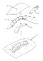
- FIGS. 1A and 1Bdepict one embodiment of a negative pressure therapy device as viewed from the top and from the side perspective.
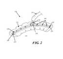
- FIG. 2depicts an embodiment of a negative pressure therapy device as viewed from above in which the device is designed to be emptied and re-evacuated.
- FIG. 3depicts an embodiment of the negative pressure therapy device as viewed from above in which the collection chamber is a segmented collection chamber.
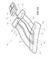
- FIG. 4depicts an embodiment of the negative pressure therapy device in which an occlusive layer is placed over the collection chamber.
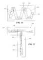
- FIG. 5depicts an embodiment of the negative pressure therapy device in which the collection chamber comprises corrugated tubing segments interspersed with discrete collection members.
- FIG. 6Ais a perspective view of another embodiment of a negative pressure therapy device
- FIGS. 6B and 6Care axial cross-sectional views of the device in FIG. 6A , before and after the application of reduced pressure, respectively.
- FIG. 7is a schematic perspective view of two wound coverings joined together.
- FIG. 8depicts another embodiment of the negative pressure therapy device, comprising a split support.
- FIG. 9Ais a perspective view of another embodiment of a negative pressure therapy device comprising an elastic collection channel
- FIGS. 9B to 9Dare schematic cross-sectional views of the device in FIG. 9A before, during and after stretching, respectively;
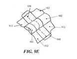
- FIG. 9Eis a schematic perspective view of two negative pressure therapy devices joined together.
- FIGS. 10A to 10Care schematic cross-sectional views of another negative pressure therapy device with reinforced apertures, before, during and after stretching, respectively.
- FIGS. 11A to 11Care schematic cross-sectional views of another negative pressure therapy device comprising an open longitudinal channel, before, during and after stretching, respectively.
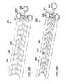
- FIG. 12is a schematic illustration of an elongate negative pressure therapy system arranged around a perimeter of a wound.
- FIG. 13is schematic illustration of an elongate negative pressure therapy system arranged in a spiral orientation about a wound.
- FIG. 14is schematic illustration of an elongate negative pressure therapy system arranged in a zig-zag orientation about a wound.
- FIG. 15is schematic illustration of an elongate negative pressure therapy system arranged in a T-orientation about a wound.
- FIGS. 16A and 16Bare perspective views of another example of a negative pressure therapy system in a contracted and stretched configuration, respectively.
- FIGS. 17A and 17Bare perspective views of another example of a negative pressure therapy system in a stretched and a contracted configuration, respectively.
- FIG. 18Ais a perspective view of another example of a negative pressure therapy system
- FIGS. 18B and 18Care end elevational views of the negative pressure therapy system in FIG. 18A in bent and straightened configurations, respectively.
- FIG. 19is an inferior perspective view of another example of a negative pressure therapy system.
- FIGS. 20A to 20Dare schematic cross-sectional views of the deployment of one example of a negative pressure therapy system
- FIGS. 20E and 20Gare perspective views of the negative pressure therapy system of FIGS. 20A to 20D in an expanded and retracted configuration, respectively
- FIG. 20Fis a detailed perspective view of the proximal end of the negative pressure therapy system in FIGS. 20E and 20G .
- FIGS. 21A to 21Dare schematic cross-sectional view of the deployment of another example of a negative pressure therapy system.
- Infections of surgical incisions and other woundsmay result from bacterial growth that occurs in small pockets of fluid collections that may form within the subcutaneous and/or subcutaneous tissues. These small fluid collections lack blood flow and thus may provide inadequate immune function or antibiotic penetration to prevent or treat infection. Once contaminated with bacteria, there can be unfettered growth in these areas. Thus, by reducing the formation of these fluid collections, the risk of a wound infection may be reduced. Although some closure techniques utilize dermal or deep sutures to reduce the formation of these fluid pockets, these sutures may also act as foreign bodies that may increase the risk of wound infection. Furthermore, improper suturing technique may still leave significant dead space under the skin that allows for fluid to collect and eventually become contaminated by bacteria. In addition to wound infection, wound healing may inhibited by excessive tension on the wound.
- Excessive tensionmay result from sutures or other wound closure devices that exert focal forces on portions of the incision or wound, and may also lead to increased scarring. Tension across a wound may also for other reasons, such as during post-closure movement, the force of gravity, etc.
- a moist wound healing environmentmay promote more rapid re-epithelialization of wounds by facilitating cell migration toward the wound center, in contrast to current gauze dressings that create a dry wound environment.
- surgical and other woundsundergo of immune cell infiltration, inflammation and subsequent edema.
- the immune responsemay be an integral process of wound healing, but the ensuing edema may also be an impediment to healing.
- proper healingrequires oxygen and nutrients which require adequate perfusion to the incision site which may be impeded by some of the immunological processes.
- a negative or reduced pressure wound therapy systemmay be used to treat of areas of skin trauma that have been surgically closed, or other types of elongate lacerations or wounds.
- the negative pressure wound therapy systemmay comprise a sealant layer and a collection chamber.
- the sealant layermay be designed such that it can form a seal around a surgically closed area of skin trauma, such as the surgical incision, and form a sealed enclosure or space.
- the sealant layermay comprise a single piece or body, while in other examples, the sealant layer may comprise multiple pieces that may be applied together to form an enclosed space or area.
- the sealant layermay also comprise a single layer of material, or multiple layers of materials.
- the sealmay be sufficiently air tight so that the pressure in the sealed enclosure or space may be reduced and maintained at a reduced level.
- the negative pressure therapy systemmay also comprise a collection chamber that is configured to distribute the reduced pressure applied to the surgically closed incision site along the length of the incision or wound.
- the negative pressure therapy systemmay also be used to treat a surgical incision left open to heal by secondary intention, or by delayed primary closure (i.e. third intention).
- the systemmay comprise a collection chamber in continuity to a surgical incision that is sealed in a closed system as created by a sealant layer.
- the collection chamberwhen activated, may generate a negative pressure at the surgical incision site to promote healing, remove exudate, and/or reduce infection rates, for example.
- the system provided hereinmay have an elongate configuration and may be sized or configured to conform to the length of the surgical incision.
- the collection chambermay be integrally formed or pre-attached to a sealant layer, or the collection chamber and the sealant layer may be configured to permit the collection chamber to be positioned under the sealant layer.
- the systemfurther comprises a suction apparatus.
- the suction apparatusWhen the suction apparatus is used with the system, the suction apparatus may be configured to be in communication with the sealed enclosure or space.
- the suction apparatustogether with the sealant layer and collection chamber, may form a closed system for treating a surgical incision or other type of wound.
- the suction apparatuswhen engaged, may be used to reduce the level of pressure located inside the sealed enclosure by forcefully expanding the volume of air located within the sealed enclosure.
- the suction sourcemay be a closed or open system.
- the suction apparatusmay be a syringe, a powered pump, a Venturi system, a forced expansion device, constant force spring device, or a static negative pressure device, or any suitable active or passive suction source.
- the suction sourcemay be integrally formed with the collection chamber.
- the suction sourceis connected to the collection chamber through the use of an extension tube.
- the systemfurther comprises a contact layer.
- the contact layermay be configured to permit fluid communication with the collection chamber.
- the contact layermay be placed in contact with the surface of the surgically closed area of skin trauma.
- the contact layermay only be in contact with the surgically closed area of skin trauma and may not be in contact with the area surrounding the site of trauma.
- the contact layermay be in contact with both the area of skin trauma and the area surrounding the area of skin trauma. The contact layer may facilitate the continuity of fluid communication between the collection chamber and the surgical area of skin trauma.
- the contact layermay comprise a porous material or other structure comprising air spaces, including, but not limited to, foam, a stacked mesh matrix, gauze, cotton, a sponge, or any known suitable material in the art.
- the contact layermay serve as a delivery vehicle for delivery agents.
- the delivery agentsmay include, but are not limited to, growth factors, antibiotics, antimicrobial agents, or any suitable delivery agent.
- the agents used to improve healingare integrated with the contact layer.
- the agents usedare integrated or located with the collection chamber.
- the systemfurther comprises a protective layer.
- a protective layermay be used to surround the surgical area of skin trauma.
- the protective layermay be attached or adhered to the area of skin surround the area of skin trauma.
- a pressure sensitive adhesive on the underside of the protective layermay provide the attachment or adherence properties to the skin.
- a protective layermay also be used to form a seal in combination with a sealant layer. The seal is airtight, or may be semi-permeable or impermeable to water vapor.
- the protective layermay be sized to the surgical area of skin trauma such that it fits around the area of skin trauma.
- the protective layermay be cut to size, but in other embodiments, the protective layer may comprise perforations or other pre-defined separation structures to facilitate the sizing.
- the protective layermay have a thin central peel-away strip or layer that may be removed after the protective layer has been placed around the area of skin trauma. In such embodiments, a wider contact layer may be placed over the protective layer.
- the protective layermay be used to affix the contact layer to the surgical area of skin trauma, and may protect the underlying skin or tissue from trauma associated with removal of the contact layer to access the surgical site.
- the protective layercan be any known material suitable for protecting the skin surrounding the skin trauma from maceration.
- the protective layermay comprise any of a variety of foam and/or hydrocolloid materials, including Duoderm® wound care products.
- the collection chamber of the static negative pressure therapy systemmay be configured to distribute the pressure levels applied to the incision site over the length of the surgically closed area of trauma.
- the collection chambermay be in a pre-evacuated state prior to being placed on the surgically closed incision area of skin trauma.
- the collection chamberonce in communication with the area of skin trauma, can then be activated to apply reduced pressure to the area of skin trauma.
- the collection chambercomprises a tubular structure.
- the tubular structuremay comprise a rigid tube, for example, a moldable or flexible tube.
- the tubemay comprise a deformable or elastic support that permit the tube to be bent or shaped into a particular configuration while also allowing the tube to holding or biasing the tube in that configuration.
- the support structuremay comprise a wire mesh cage or frame surrounding the tube, coupled to the inner lumen of the tube, or otherwise supporting the tube.
- the tubehas a wire support structure integrally within the walls of the tube.
- the support structuremay also comprise a moldable plastic material, or the tubing itself may comprise a moldable plastic including. Moldable materials include, but are not limited to, thermoplastics, elastomeric materials, or any suitable moldable material.
- the collection chambermay be configured for single use only, while in other embodiments, the collection chamber may be emptied and re-evacuated during use.
- the collection chamberis a flexible tube which comprises one or more corrugated sections.
- the corrugated tubing sectionmay be flexible and can conform to the surface topology of the surgically closed area of skin trauma.
- the corrugated tubing sectionsmay allow the flexible tubing to conform to the two-dimensional or three-dimension configuration of the wound or incision and allows the tubing to passively adjust in response to changes in the wound configuration as the patient moves or as the wound heals.
- the flexible tubemay comprise entirely of corrugated tubing, while in other embodiments, the flexible tubing is corrugated tubing sections with discrete collection members or non-corrugated sections located therebetween.
- the non-corrugated sectionsmay be rigid, or may be semi-rigid or flexible but with less flexibility than the corrugated sections. Some embodiments may comprise at least one non-corrugated section located within the tubing, while other embodiments may comprise two or more non-corrugated sections located along the tubing.
- the tubular segmentsmay be connected by corrugated tubes that provide fluid communication along a length of the tubing and/or provide flexibility to the tubing such that the entire collection chamber structure, the rigid non-corrugated sections and the flexible corrugated tubing sections overall permit conformation to the skin or surgical site as it moves. Sometimes, flexible tubing may mitigate the discomfort to the patient or reduce the localized pressure points from the treatment system.
- both the flexible tubing segments and the rigid collection sectionsmay be embedded into the sealant layer, coupled to the sealant layer, or integrally formed with the sealant layer. In some embodiments, only the discrete collection members are coupled or embedded into the sealant layer, while the flexible tubing segments are not.
- Some embodiments of the systemcomprise a collection chamber and a sealant layer, where the sealant layer and the collection chamber are in fluid communication with an area of skin trauma.
- Fluid communicationmay be provided by a series of openings in the sealant layer and the collection chamber which provide fluid communication between the area of skin trauma and the collection chamber.
- the openingsmay be located longitudinally oriented along a length of the collection chamber, with corresponding openings of the sealant layer aligned with the openings in the collection chamber. Fluid, or any other suitable matter, may then be drawn up from the surgically closed area of skin trauma into the collection chamber.
- the fluidmay passes first through the contact layer, and then through the holes connecting the sealant layer and collection chamber.
- the series of openings located throughout the collection chambermay allow for the distribution of pressure to the area of skin trauma and reduce or prevent areas of localized pressure or fluid build-up that may be greater in some areas and less in other areas.
- the collection chamberfurther comprises a one-way flow valve.
- the one-way flow valvemay be used to assist in the emptying of the collection chamber.
- the one-way flow valvemay also be used to re-create the reduced pressure, or pre-evacuated, level of pressure inside the collection chamber.
- the one-way flow valvemay be used to facilitate both empting of the collection chamber and re-evacuation of the collection chamber.
- the one-way flow valvemay serves to facilitate the re-evacuation of the collection chamber by facilitating the attachment of a suction source to the collection chamber through the valve and allowing the suction source to remove air molecules from the collection chamber.
- the suction sourcemay also be used to remove exudate or air from the collection chamber through the use of the one-way flow valve.
- a first one-way flow valveis used to empty the collection chamber and a second one-way flow valve is used to re-evacuate the collection chamber.
- the one-way flow valvemay be integrated with the collection chamber.
- the one-way flow valveis attached to a removable plug used to occlude one end of the collection chamber.
- a plurality of one-way valvesmay be provided, with one or more valves located in or associated with the series of openings to reduce backflow of air or material out of the collection chamber or the sealant layer and back into the area of skin trauma.
- the one-way valvesmay have any of a variety of configurations, including duckbill or flap valves.
- a segmented collection device or other multi-cavity devicemay be used in place of a single chamber collection chamber in some embodiments.
- a segmented collection chambermay comprise a first chamber and a second chamber which may or may not be in fluid communication with each other.
- the first chamberis in direct communication with the sealant layer whereas the second chamber is in communication with the first chamber.
- one or more of the segments or chambersmay be a source of suction.
- the suction sourcemay comprise a non-powered or passive actuating and regulating mechanism, including but not limited to a spring mechanism such as a constant force spring.
- the passive actuating and regulating mechanismmay be used to apply and maintain a level of pressure inside the sealed enclosure or space between the collection chamber and the sealant layer.
- the dual chamber collection chambercomprises a reciprocating mechanism including, but not limited to, a plunger.
- the plungermay be manually distracted, or may be passively distracted, such as when attached to a constant force spring.
- the second chamberexpands the volume of air located in a joint volume of space shared between the sealed enclosure and the dual chamber collection chamber.
- One or segments or chambersmay also comprise a powered or active actuating and regulating mechanism.
- the systemmay also be sized or configured to conform to the length of the surgically closed incision.
- the collection chamberconforms to the length of the closed incision area of skin trauma by being stretched to the length of the wound.
- the collectioncan be made from a hydrocolloid material. Such a material allows the collection chamber to be stretched to a new desired length and remain at that length after the stress causing the change in length has been removed.
- the systemmay be made from a hydrocolloid or any suitable material.
- the systemmay be shortened to the length of the closed incision.
- the systemcan be cut to the length of the closed area of skin trauma.
- the cut end of the collection chambermay be self sealing upon the application of pressure to the collection chamber.
- the collection chambercan be sealed after it has been cut.
- the collection chambercan be sealed with an end cap, a plug, an occlusive sealant sheet, an end cap with a one way flow valve, a constant force spring, a reduced pressure system, or any suitable means for sealing the end of the collection chamber.
- the structure used to seal the end of the collection chamber that has been adjusted to conform to the length of the skin traumais configured to resist removal once affixed to the collection chamber.
- the structure used to seal the end of the collection chamber that has been adjusted to conform to the length of the skin traumamay be a removable structure.
- the systemincludes a series of collection chambers lined up in parallel or serially with each other.
- one or more collection chambersmay be removed from the series of collection chambers to accommodate the width of the closed incision area of skin trauma.
- one or more collection chambersmay be replaced upon filling or clogging.
- the contact layermay be adjusted to conform to the length of the surgically closed area of skin trauma.
- the contact layermay be lengthened or shortened based upon the length of the closed incision or wound.
- the contact layermay be cut to the length of the closed incision.
- the collection chamber, the contact layer, and/or the sealant layermay be adjusted to conform to the length of the surgically closed incision.
- only the collection chamberis adjusted to conform to the length of the incision before the system is placed on the patient, while in other embodiments, only the contact layer or the sealant layer is adjusted to conform to the length of the surgical incision before the system is placed on the patient.
- the collection chamber, the contact layer, and the sealant layermay each be individually adjusted to conform to the length of the incision or wound before being placed on the patient.
- the collection chamber, the contact layer, and the sealant layerare integrated together, such that the system is adjusted to conform to the length of the surgically closed incision or wound as a unit.
- the system provided hereinincludes a sealant layer for creating a seal with the surface of the patient.
- the sealis air tight.
- the sealant layercomprises a flexible impermeable material.
- the sealant layeris a semi-rigid material.
- the sealant layermay provide tensile support to the surgically closed area of skin trauma. A semi-rigid sealant layer would further alleviate mechanical tension on the surgically closed area of skin trauma as the trauma heals.
- the system provided for hereinfurther includes absorbent beads.
- the absorbent beadsare located in the incision or wound, and/or the collection chamber.
- the systemmay comprise antimicrobial agents.
- Antimicrobial agentsinclude, but are not limited to, silver, iodine, chlorhexidine or any other suitable antimicrobial agent.
- Some of the examples provided hereinare configured to create a level of pressure within the sealed enclosure encompassing the surgically closed area of skin trauma.
- the level of pressure createdis between about 0.001 and about 1 atm.
- the level of atmospheric pressure underneath the sealant layermay be reduced to no lower than about 0.001 atm, about 0.005 atm, about 0.01 atm, about 0.05 atm, about 0.1 atm, about 0.2 atm, about 0.5 atm, about 0.7 atm, or about 0.9 atm.
- the atmospheric pressure underneath the sealant layermay be reduced to about 0.8 atm or less, but in other embodiments, may be reduced to less than about 0.7 atm, 0.6 atm, about 0.4 atm, about 0.3 atm, about 0.2 atm, about 0.1 atm, about 0.07 atm, about 0.03 atm, about 0.007 atm, or to about 0.003 atm or less.
- the contact layer, the sealant layer and/or the collection chambermay be made from transparent materials.
- the transparency of the materialsmay facilitate more accurate placement of the system over the surgical incision or wound by the clinician to more accurately place the system, and/or may permit visualization of the incision or wound with breaking the seal.
- a method for applying a reduced pressure therapy system to a surgically closed area of skin traumacomprises (a) sizing a collection chamber, a protective layer and a sealant layer to a surgically closed area of skin trauma; (b) forming a seal around the surgically closed area of skin trauma; (c) activating the collection chamber to deliver reduced pressure evenly distributed to the surgically closed area of skin trauma; and (d) removing the system after re-epithelialization of the surgically closed area of skin trauma.
- Wound re-epithelializationoccurs between 2 days and 5 days after the skin trauma has been surgically closed. In some embodiments wound re-epithelialization occurs 3 days after closure.
- wound re-epithelializationoccurs 4 days after closure. In some embodiments wound re-epithelialization occurs 5 days after closure. In some embodiments, wound re-epithelialization occurs earlier than 5 days after wound closure. In some embodiments, wound re-epithelialization occurs earlier than 4 days after wound closure. In some embodiments, wound re-epithelialization occurs earlier than 3 days following wound closure.
- a method for treating an area of skin trauma using a reduced pressure therapy systemcomprising: (a) cutting a protective layer to the shape of an area of skin trauma; (b) attaching the cut protective layer to an area of intact skin surrounding the area of skin trauma; (c) cutting a flexible adhesive dressing with an integrated layer of foam to a desired size, said flexible adhesive dressing integrated with said layer of foam in fluid communication with a flexible tubing; (d) placing the dressing over said surgically closed area of skin trauma to form a sealed enclosure; (e) configuring the tubing with an end piece; (f) charging the device; (g) recharging the device as necessary to remove exudates and to restore reduced pressure inside said enclosure; and (h) removing the device after wound re-epithelialization.
- the skin traumais selected from a cut, puncture wound, surgically created incision, or any other wound which is suitable for being closed surgically.
- FIGS. 1A and 1Billustrate one embodiment static negative pressure device 100 .
- the device 100comprises a sealant layer 110 (also sometimes referred to herein as a sealant structure) and a collection chamber 120 (also sometimes referred to herein as a collection structure) configured to distribute pressure along a surgical area of tissue trauma, such as the length of a surgical incision.
- the deviceis described herein the context of the tissue being skin, although it should be appreciated that the device can be used with biological tissue other than skin.
- the negative pressure therapy devicemay include a contact layer 130 .
- the contact layer 130provides fluid communication between the collection chamber 120 and the area of skin trauma.
- the contact layer 130may comprise a foam, mesh, gauze, sponge, particulate matter, a stacked mesh matrix, or any other suitable porous biocompatible material, for example.
- the contact layer 130may be put into contact with the surface of the surgically closed area of skin trauma.
- the contact layer 130may be configured to maintain continuity of the air/fluid spaces through the surgical site, which may reduce the occurrence of isolated fluid or air pockets in the enclosed space formed by the surgical area and the sealant layer 110 .
- the contact layermay be within the borders the skin trauma surface and not contact, overlap or cover the surrounding tissue area adjacent to the skin trauma.
- the contact layermay be placed in contact with the adjacent tissue surrounding the skin trauma, in addition to the region of skin trauma itself. As shown in FIG.
- the contact layer 130 , the sealant layer 110 , and the collection chamber 120may be coupled or integrated together.
- a pre-coupled or integrated designmay permit the device 100 to be placed in contact with the skin trauma surface in one step.
- the contact layeris placed in contact with the skin trauma surface. Once positioned, the contact layer is then covered by the sealant layer with an integrated collection chamber to form a sealed enclosure or space.
- the sealant layermay be affixed to the area of skin surrounding the trauma area by any suitable materials or mechanisms known to one skilled in the art, including but not limited to, tape, glue, or a suitable biocompatible adhesive product.
- the suction apparatus 140may be configured to create a level of reduced pressure inside of the collection chamber 120 .
- the collection chamber 120may be in a pre-evacuated state prior to being positioned on the surface of the skin trauma, while in other embodiments, the collection chamber 120 may be evacuated after positioning, or after coupling to the suction apparatus 140 .
- the collection chamber 120may be pre-evacuated at the point-of-use or at the point-of-manufacture.
- the suction apparatusmay be coupled to the collection chamber prior to being positioned on the surface of the skin trauma, and in still other embodiments, the suction apparatus and the collection chamber may be integrally formed.
- the collection chambermay be sized to the length of the surgically closed area of skin trauma by cutting the collection chamber or by detaching or one or more portions of the collection chamber.
- the collection chambermay have one or more pre-defined separation zones with reduced thickness to facilitate length reductions.
- a suction apparatuscan then be attached or otherwise used to close the cut or separated end of the collection chamber.
- FIG. 1Ashows the device 100 with a collection chamber 120 in which a suction apparatus 140 comprises with a constant force spring mechanism 142 has been integrated with the collection chamber 120 .
- the constant force spring mechanism 142 of the suction apparatus 140is engaged, the slidable seal or reciprocating mechanism 144 may be drawn back to create and maintain a constant level of pressure inside the sealed enclosure.
- FIG. 1Athe device 100 has been sized to the length of a wound by cutting one end 122 of the collection chamber 120 .
- FIG. 1Afurther depicts the non-suction apparatus end 122 being occluded by an end plug 124 .
- the deviceis further sealed in FIG. 1A using an end sealant structure 126 .
- the non-suction apparatus end 122 and/or the end plug 124may be configured to detachable or non-detachable.
- a gluemay be used to irreversibly attach the end plug to the apparatus end 122 .
- the length of the collection chambermay be adjusted based upon the length of the surgical incision or wound.
- the length of the surgical incision or woundmay be generally linear or may be non-linear.
- the length of the collection chamberis about the length of the surgical wound, while in other examples, the collection chamber length may be about +10%, about +20%, about +30% or more, about ⁇ 10%, about ⁇ 20%, or about ⁇ 30% or less than the length of the surgical wound.
- surgical wounds with non-elongate configurationmay also be treated.
- branching or stellate surgical woundsmay be treated, using one or more devices.
- the surgical wound or incisionmay be characterized as the affected length of a partially dehisced surgical wound.
- the sealant layer and/or contact layermay be configured to seal or cover the dehisced segment, or the entire wound or incision. Exemplary methods for treating non-elongate wounds are described later below.
- the collection chamber per centimeter lengthmay have a volume in the range of about 100 mm 3 to about 10,000 mm 3 or more, sometimes about 500 mm 3 to about 7,000 mm 3 , and other times about 1,000 mm 3 to about 5,000 mm 3 .
- the collection chamber 120may be in fluid communication with the skin trauma site through the contact layer 130 of the device 100 .
- the collection chamber 120 and the sealant layer 110are integrally formed.
- the collection chamber 120may comprise a plurality of openings 150 that may align or correspond to a plurality of openings 150 ′ in the sealant layer 110 to provide fluid communication between the skin trauma and collection chamber 120 through the contact layer 130 and the sealant layer 110 .
- the series of openings 150 and 150 ′may permit distribution of the pressure changes applied to the area of skin trauma across the length or region of the skin trauma.
- the spacing, size or shape of the openings 150 and 150 ′ along the collection chamber 120 and/or the sealant layer 110may be uniform or non-uniform.
- the collection chamber 120 and the sealant layer 110may comprise separate structures that are configured for coupling.
- the adjacent surface of the collection chamber 150 and/or the sealant layer 110may comprise an adhesive or slip-resistant surface.
- the collection chamber openings 150 and/or openings in the sealant layer 120may form complementary interfit to facilitate alignment.
- the collection chamber openings 150 and/or the sealant layer openings 150 ′may protrude into the opening in the corresponding structure.
- the collection chamber openings 150 and the sealant layer openings 150 ′may comprise complementary sealable snapfit.
- the collection chambermay comprise an elastically or plastically deformable material or a bendable configuration. This may permit the collection chamber to conform to the contours of a surgically closed area of skin trauma, and may permit the collection chamber to exhibit at least some conformational change in response to body movement.
- the collection chamber 120comprises regions or zones of flexible ribbing 128 along the length of the collection chamber 120 .
- the ribbing 128allows the collection chamber 120 to be shaped and molded by the user and further maintains the user defined configuration.
- the portions of the collection chamber 120 between the flexible ribbing 128may be rigid, semi-rigid or flexible.
- a collection chambermay also be configured to at least partially rotate in addition to bending.
- different sizes or configurations of openingsmay be provided around the circumference of the collection chamber and may be selected for use by rotation.
- the unused openingmay be sealed by applying a sealant layer over the unused openings.
- the openingsmay be presealed and the selected seals may be utilized by removing the pre-attached seal(s) from them.
- FIG. 2shows another embodiment of a negative pressure therapy device 200 in which the device 200 is configured to be re-evacuated or recharged.
- the device 200comprises an integrated contact layer 230 , sealant layer 210 and collection chamber 220 .
- the contact layer 230may be placed in contact with the surface of the skin trauma and a seal may be formed between the skin surrounding the skin trauma using the sealant layer 210 .
- the collection chamber 220may be integrated with the sealant layer 210 and is in fluid communication with the contact layer and the enclosed surgical site through a series of openings 250 in the collection chamber 220 and the contact layer 230 , but in other examples, the collection chamber and the sealant layer may be separated components that may be attached using adhesive or mechanical mechanisms.
- the alignment of the collection chamber openings and the sealant layer openingsmay be facilitated by configuring either the collection chamber openings and/or the sealant layer openings with complementary interfit designs.
- the base sealant layermay lack pre-formed openings, but the collection chamber openings may comprise sharpened or penetrating structures to permit formation of sealant layer openings when the two components are coupled together.
- the collection chamber 220may be in a pre-evacuated state wherein a level of reduced pressure is already present inside.
- the collection chamber 220can be at atmospheric pressure when placed on the patient, and a reduced level of pressure can be created in the collection chamber using an external evacuator device 270 , such as a durable medical equipment evacuator.
- the external evacuator device 270may be positioned in an opening 276 of an evacuator fitting 278 on the collection chamber 220 .
- the evacuator fitting 276is in fluid communication with the collection chamber 220 .
- the evacuator fitting 276may be configured as a one-way flow valve that allows air molecules or other materials to be removed from the collection chamber 220 while resisting entry of air molecules or other materials into the collection chamber.
- the collection chamber 220comprises flexion regions 228 with ribbing, but in other examples, a substantial length of the collection chamber comprises a flexible material.
- FIG. 2also depicts a collection chamber 220 with one end 222 occluded with an end plug 224 .
- the other end 222 ′ of the collection chambermay be fitted with a one-way flow valve 260 .
- the device 200may comprise a separate one-way flow valve 260 for facilitating the emptying of the collection chamber 220 when the collection chamber 220 is filled with exudate or other matter.
- the collection chambercan then be re-evacuated using an external evacuator 270 introduced through the opening 276 of the evacuator fitting 278 .
- the one-way flow valve 260 and the means for evacuating the collection chamber 220are the same structure.
- the one-way flow valve and the means for evacuating the collection chamberare two different structures, as shown in FIG. 2 .
- FIG. 2also shows a device 200 with a moldable collection chamber 220 .
- the negative pressure therapy device 300may comprise a multi-chamber collection system 370 , comprising a first chamber 372 and a second chamber 373 .
- the multiple chambersmay be connected, or may be separate.
- the first and second chambers 372 and 373may be in fluid communication with each other at an interconnecting opening 374 .
- the first chamber 373 of the dual chamber collection chamber 370has a series of openings 350 that configured to provide fluid communication with the contact layer 330 of the device 300 .
- the second chamber 372 of the dual chamber collection chamber 370can be fitted with a reciprocating mechanism for regulating pressure.
- FIG. 3The second chamber 372 of the dual chamber collection chamber 370 can be fitted with a reciprocating mechanism for regulating pressure.
- the second chamber the reciprocating mechanismis shown as a spring 374 attached to a spring housing 378 on the end of the dual chamber collection chamber 370 opposite to the sealed end with end plug 324 .
- the springcreates a moving seal 376 through the use of a plunger like apparatus.
- the moving seal 376self-regulates changes in pressure in the dual chamber collection chamber 370 and moves in response to these changes.
- FIG. 4illustrates another embodiment of a negative pressure therapy device 400 , in which contact layer 430 , the collection chamber 420 , and the sealant layer 410 of the device are not integrated and the sealant layer 410 is placed above or over the collection chamber 420 and contact layer 430 .
- the contact layer 430is placed in contact with the surgically closed area of skin trauma.
- a moldable collection chamber 420 with ribbing 428 tomay be used to manipulate configuration of the chamber 420 for contact and coverage with the contact layer 430 .
- a series of openings 450 located in the collection chamber 420provides for fluid communication between the contact layer 430 and the collection chamber 420 .
- the collection chamber 420may then be evacuated through the use of suction apparatus 440 .
- the suction apparatuscan be a syringe, a powered pump, or a forced expansion device.
- the suction apparatus 440is preferably in fluid communication with the collection chamber 420 through a one-way valve 460 .
- a sealant layer 410can then be placed over the collection chamber 420 and the contact layer 430 to form a sealed enclosure with the wound.
- FIG. 5depicts another embodiment of a device 500 , in which the collection chamber 520 comprises corrugated tubing segments 582 with discrete collection members 580 interspersed throughout the collection chamber 520 .
- the collection chamber 520comprises corrugated tubing segments 582 with discrete collection members 580 interspersed throughout the collection chamber 520 .
- One end 522 of the corrugated tubingis sealed with an end plug 524 or other closed configuration.
- the other end 522 ′ of the device 500may be coupled or integral with a suction source 540 , such as a constant force spring, a powered suction pump, a durable medical equipment evacuator, or any suitable suction source.
- the contact layer 530 of the device 500is integrated with the sealant layer 510 and the collection chamber 520 in FIG. 5 . Once placed on the patient, the corrugated tubing segments 582 allow the collection chamber to conform to the surface topology of the patient.
- the deviceallows the device to move with the patient.
- the corrugated tubing segmentsallows for significant expansion and compression of the underlying skin.
- the discrete collection member 580are in preferably fluid communication with the contact layer 530 and skin trauma surface through a series of discrete openings 550 .
- an elongate reduced pressure therapy systemmay be applied along the length of an elongate wound with wound edges that may be approximated.
- the elongate reduced pressure therapy systemmay also be used with incisions already closed by sutures, staples or adhesives, for example.
- the use of a reduced pressure therapy system on a closed incisionmay provide more uniform force distribution along an incision, by exerting additional closure forces against tissues not immediately contacting a suture or staple, for example.
- a negative pressure therapy systemin some instances, may also resist separation of the wound edges. In some instances, the negative pressure therapy system may resist stretching of the newly formed connective tissue, which may reduce the extent of scarring.
- the wound treatment systemmay comprise a negative pressure system that is configured to provide both mechanical tension reduction and reduced pressure effects on the incision or wound.
- the reduced pressure effectsmay or may not include the displacement of the wound edges toward each other by reducing the pressure of the space between the wound edges and/or from pushing or pulling by the sealant layer as the sealant layer is contracted around the support.
- a reduced pressure therapy systemmay also comprise an elastic sealing layer or a sealing layer configured with one or more elastic members.
- the sealant layermay be attached or adhered to one side of the incision or wound and then stretched and attached to the other side of the incision or wound. Once in place and with the stretching force relieved, the sealant layer or its elastic member may exert opposing forces on each side of the wound to augment the edge approximation and draw the incision or wound edges together.
- the elastic membersmay be oriented in a transverse position to the longitudinal orientation of the incision or wound, but in other examples, the elastic member may be oriented in multiple directions.
- the sealant layer or the elastic membermay comprise a material such as silicone rubber, polyisoprene or other elastomeric material which possesses a sufficient restoring force to pull tissue together when adhered to opposing incision or wound edges in a stretched configuration.
- one or more elastic membersmay be applied or attached to the sealant layer after the sealant layer has been applied to the incision site or wound site.
- FIGS. 6A to 6Cdepict another example of a wound treatment device 600 comprising a sealant layer 602 and an elongate support 604 .
- the elongate support 604may be configured with an elongate central channel 606 that may be placed along or over an incision or elongate wound.
- the device 600may comprise multiple channels in direct communication with the elongate wound.
- the elongate central channel 606has an open channel configuration that is exposed to the incision or wound along a portion if not all of its longitudinal length, but in other examples, the elongate channel 606 may have a generally closed configuration with a plurality of longitudinally arranged openings along a segment of the channel or the entire channel.
- An open channel or a plurality of longitudinally arranged openingsmay permit the application of reduced pressure along a length of the wound while possibly reducing the risk that clogging or transient opposition of tissue surfaces may affect the distribution of pressure reduction and/or fluid suction.
- the channel, or the segment of the channel in communication with the incision or woundmay have a length of at least about 1 cm or more, 3 cm or more, sometimes about 10 cm or more, and other times about 20 or about 50 cm or more.
- the device 600may comprise a length of about 70 cm, 100 cm or even 150 cm, which may be cut or shortened to a smaller length.
- the support 604 and/or sealant layer 602may be provided in the form of a roll or a folded form, which is then dispensed and cut as needed.
- the device 600(or other devices described herein) may be used to treat any of variety of incisions or wounds, but in some specific examples may be used to a variety of elongate incisions or wound, including but not limited to linear or curvilinear incisions or wounds.
- woundsmay include but are not limited to any of a variety of traumatic lacerations or cuts, sternotomy incisions, laparotomy incisions, perineal prostatectomy incisions, vein harvesting incisions, C-section incisions, and the like.
- the elongate central channel 606may be positioned along an incision or elongate wound and then secured or sealed by placing the sealant layer 602 over the incision and support 604 .
- the sealant layer 602 and the support 604may be integrally formed or pre-attached to each other, such that the sealant layer 602 and the support 604 may be applied to an incision or wound in a single step.
- the sealant layer 602may have a size and configuration to permit complete sealing of the entire perimeter of the incision and the support 604 , but in other examples, one or more accessory seals 608 and 610 may be used.
- the sealant layer 602may comprise an adhesive on one or more surfaces. In FIG.
- adhesivemay be provided along the lateral regions the undersurface of the sealant layer 602 , leaving a strip or middle section of the sealant layer 602 free of adhesives.
- end seals 608 and 610may be used to facilitate sealing about the ends 612 and 614 of the sealant layer 602 , but in other embodiments, accessory seals may be used anywhere to provide additional sealing.
- the sealant layer, support, and/or one or more accessory sealsmay be pre-configured with a connector or port which may be used to coupled the device 600 to a reduced pressure source.
- one of the end seals 610is pre-configured with a connector 616 that may be used to attach a suction device 618 using an optional connector tube 620 .
- the suction source or a connector tubemay be configured to pierce and form an aperture through the sealant layer or accessory seal.
- the suction device 618may be integrally formed with the end seal, sealant layer and/or support 604 .
- the support 604may optionally comprise one or more side flanges or flaps 622 to one or both sides of the elongate channel 606 .
- Each of the side flaps 622may have a width (or dimension transverse to its longest dimension) in the range of about 2 mm to about 50 mm or more, sometimes about 10 mm to about 40 mm, and other times about 20 mm to about 30 mm.
- the side flapsmay have an average thickness in the range of about 0.5 mm to about 5 mm or more, sometimes about 0.75 mm to about 3 mm, and other times about 1 mm to about 2 mm.
- the thickness of the side flapmay or may not be uniform, and in some examples, the thickness may taper or reduce in a central to peripheral direction, or vice versa.
- the side flaps 622may comprise the same or different material as the material about the elongate channel 606 .
- the support 604 and/or the side flaps 622may be rigid, semi-rigid or flexible, and may comprise silicone, urethane, or the like, and may or may not comprise a coating.
- one or more sections of the support 604may comprise an ant-infective coating, including but not limited to a silver alloy or chlorhexidine coating.
- the side flaps 622may or may not comprise an adhesive on its tissue contacting surface 624 and/or its sealant layer contacting surface 626 .
- the support 604may further comprise a cap structure 628 .
- the cap structure 628may be located on the upper surface of the elongate channel 606 and may be configured to project to one or both sides of the elongate channel 606 .
- the cap structure 628may project anywhere from about 0 mm to about 15 mm or more, sometimes up to about 5 mm, and other times up to about 10 mm.
- one or more elongate side channels 630may be formed between the cap structure 628 and the side flanges or flaps 622 .
- the cap structure 628may comprise rounded edges or surfaces, which may or may not reduce the risk of puncturing or damaging the sealant layer when contracted onto the support 604 .
- an accessory seal, or a sealant layer configured with regions of greater thickness, puncture resistance, or other reinforcementmay be positioned about the support 604 .
- the side flaps 622 and/or the cap structure 628may or may not have a symmetrical configuration and/or size with respect to the elongate channel 606 .
- one or more openingsmay be provided in the walls 632 between the central channel 606 and the side channel(s) 630 , but in other configurations, communication between the central channel 606 and the side channel(s) 630 may only occur about the ends of the support 604 where the sealant layer 602 may provide a common space or pocket where it may not be adhered to the skin.
- the sealant layer 602may collapse around or into the support 604 .
- sections of the sealant layer 602may be pulled or pushed into the elongate side channels 630 .
- the support 604may comprise any of a variety of indentations, openings, grooves, channels which may permit contraction of the sealant layer 602 to the support 604 , either with suction or by mechanical structures such as a clamp or pushrod, drawstring or any other complementary structure that may be attached or coupled to tighten the sealant layer 602 to the support 604 .
- this contraction of the sealant layer 602may or may not draw the wound edges 634 closer together.
- the application of reduced pressuremay also reduce the size or eliminate the gap 636 between the wound edges 634 .
- the wound treatment systemmay also comprise one or more elastic elements incorporated or attachable to the sealant layer.
- elastic bands or threadsmay be provided in the sealant layer in addition to the elastic properties of the support, if any.
- the elastic bands or threadsmay have a uniform orientation, but in other configurations, the elastic bands may be oriented in multiple directions.
- the supportmay also comprise an elastic material or structure (e.g. a spring) which may be configured to further mechanically bias the wound tissue or edges in a particular direction.
- the springmay comprise an attachable clip, which is optionally used with the support to provide additional force with elastic supports, or the contracting force with rigid supports.
- the reduce pressure wound therapy systemmay be used to treat incisions or elongate wounds that may be longer than the length of the device that is available.
- multiple devices, supports and sealant layersmay be arranged in an independent or an overlapping configuration to treat larger wounds.
- FIG. 7for example, two separate supports 700 and 702 and sealant layers 704 and 706 are positioned end-to-end and the junction region 708 is covered with a third sealant layer 710 .
- Use of a third sealant layer 710may be useful, for example, where the support and sealant layer are supplied or manufactured in an integral or pre-attached configuration.
- the ends of the supports 700 and 702 and the sealant layer 704 and 706are depicted as touching at the junction region 708 , in other examples, partial or full gaps may be provided between supports and/or sealant layers.
- the supports and/or sealant layersmay also be arranged in a parallel fashion.
- a third sealant layerneed not be used, as one sealant layer may be overlapped over another where the sealant layer extends past the end of it associated support.
- multiple sealant layers or supportsmay be provided and used with a lesser number of supports or sealant layers, respectively.
- more than one suction devicemay be used with longer or larger support or sealant layers.
- a support 800comprise two elongate support segments 802 and 804 which are configured to be generally joined along their longitudinal lengths at a coupling interface 806 .
- a support 800 comprising separate longitudinal segments 802 and 804may be used to separately attach each segment 802 and 804 to one edge of an incision or wound (e.g. by adhesives or suturing) and are then joined together to approximate the wound edges.
- separate joinable componentsmay be easier to attach to the skin than a unibody support.
- the longitudinal segments 802 and 804may be rigid, semi-rigid or flexible, and although the segments 802 and 804 are depicted as each contributing about 50% of the structure, e.g. generally symmetrically split except for possibly the coupling interface. In other examples, however, the longitudinal segments may be asymmetrically split.
- the coupling interface 806 depicted in FIG. 8comprises a complementary set of grooves 808 and ridges 810 located along the longitudinal inner surface 812 of each segment 802 and 804 , but any of a variety of coupling interfaces 806 may be used, including other snapfits.
- locking interfaces, mechanisms or structuresmay include but are not limited to resealable adhesive layers, slide locks, hinge clamps, clips, locking pins with lockable lumens, zippers, elastic binding bands, and the like.
- structures that may be used to contract the sealant layer into a unibody supportmay also be used to contract the sealant layer into a multi-segment support and/or to couple the segments of a multi-segment support together.
- FIG. 9Adepicts one example of a negative pressure therapy system 900 comprising an elastic support 902 and an optional suction system 904 .
- An optional contact layer 906may be provided under the elastic support 902 .
- the elastic support 902is configured with one or more longitudinal conduits 908 or channels.
- the conduit or channelmay be fully enclosed or may be at least partially open.
- the conduit 908 in FIG. 9has a closed configuration with a plurality of apertures 910 to permit air or fluid communication with the underlying wound or incision.
- the lateral flaps 912 of the elastic support 904may comprise an adhesive, which may be used to at least seal a portion of the conduit 908 and the external space, if any, between the incision or wound and the apertures 910 .
- the lateral flaps 912may extend to one or both ends of the support, but in the example, depicted in FIG. 9A , end seals 914 and/or 916 may be used to facilitate sealing about the ends 918 and 920 of the support 902 .
- at least one of the end seals 916may be provided with a connector 922 for attachment of the suction system 904 , but in other embodiments, the connector may be located on the elastic support 902 .
- a large sealant layermay be used to cover a larger portion if not all of the support, and with or without a protective layer.
- some embodiments of the elastic supportmay comprise segmented non-sealing lateral flaps which are configured to elastically bring wound edges together.
- the segmentationmay facilitate the application of the elastic support in a sectional manner, but may or may not provide sealing ability, such that a sealant layer applied over the elastic support may be used to provide a sealed space about the support.
- the flaps 912 of the elastic support 902may be elastically stretched or pulled away from each other and applied in its stretched state to the incision or wound such that each flap 912 is adhered to the skin surface 922 to a respective edge of the incision or wound.
- the support 902may be sufficient stiff or rigid such that a substantial longitudinal length of the flaps 912 can be stretched, but in other configurations, a smaller portion of the flaps 912 may be pulled away, which may facilitate the application of the support to non-linear incisions or wound by permitting adherence or attachment of the support section-by-section.
- FIG. 9Edepicts how two elastic supports 902 with flaps 912 may be positioned serially or in an end-to-end fashion to treat incisions or wounds having a longer length by covering the junction 958 with an accessory seal 960 .
- the ends of the supports 902 and their flaps 912are depicted as touching at the junction region 958 , in other examples, partial or full gaps may be provided between supports and/or their flaps.
- the elastic supportmay comprise any of a variety of configurations.
- the elastic support 902may comprise an elastomeric member 926 which may augment the elastomeric properties, if any, of the flaps 912 and/or wall 928 of the conduit 908 .
- the apertures 910 of the elastic support 902may be provided directly in the elastomeric member 926 , and in some configurations the apertures 910 may also deform in shape when force is applied to the flaps 912 .
- FIG. 10A to 10Cdepicts another embodiment of an elastic support 950 with flaps 952 , wherein the apertures 954 are provided in a non-elastic structure 956 .
- FIGS. 11A to 11Cdepicts still another embodiment of an elastic support 970 with flaps 972 comprises an elastic material such that a specific elastomeric member is not used.
- the elastic support 970comprise an open channel 974 that lacks discrete apertures and instead is generally open along the length of the channel 974 to the edges 922 and space 924 of the underlying incision or wound.
- the elastic support 970may be applied to an incision 976 closed with sutures 978 or other type of incision closure such as staples.
- the sutures 978may any type of suture and may be used with any of a variety of suture techniques, including running sutures and interrupted sutures. In some variations, although the sutures 978 may generally maintain the approximation of the wound edges 980 , separation forces acting at the sutures 978 may generate focal regions of tissue tension.
- Application of the elastic support 970 to the incisionmay be used to apply additional contiguous force along a substantial length of the incision 976 , which may or may not reduce the focal tissue tension and possibly improve incision healing.
- FIGS. 12 to 15depict various examples of using an elongate negative pressure therapy system to treat non-elongate wounds.
- an elongate negative pressure therapy device 1000 and a sealant layer 1002are positioned around the perimeter of wound 1004 .
- the device 1000may comprise apertures 1006 , 1008 and 1010 of varying size. In some instances, smaller apertures 1004 may be used at distances closer to the suction source or interface 1012 , while larger apertures 1008 may be used at relatively farther distances. In still other examples, the size of the apertures may be uniform, but either the number and/or the spacing of the apertures may vary along the longitudinal length of the device.
- FIG. 13depicts another example of a negative pressure therapy device 1020 arranged in a spiral orientation with respect to a wound 1022 .
- the spiral orientationmay augment the pressure or suction about the center of the wound 1022 , compared to the device arranged depicted in FIG. 12 .
- FIG. 14is still another example of a device 1030 comprising alternating rigid sections 1032 and flexion sections 1034 arranged in a back-and-forth or zig-zag orientation along a non-elongate wound 1036 .
- the rigid sections 1032may also rotate with respect to the flexion section 1034 or other articulation of the device.
- the deviceneed not be fully located within the borders of the wound 1036 , and although all of the device apertures 1038 are located within the wound borders, in other examples one or more apertures may be located outside the border of the wound.
- FIG. 15depicts another example where multiple devices 1040 and sealant layers 1042 are used to close a non-linear surgical incision.
- the surgical incisioncomprising a T-incision with a transverse incision 1044 and a midline incision 1046 , and is treated using two open-channel devices 1040 applied to each incision 1044 and 1046 , with overlapping sealant layers 1042 .
- more than two devices and two sealant layersmay be used, e.g. one longer device may be used along the entire length of the midline incision 1046 and two smaller devices may be used along each remaining segment of the transverse incision 1044 .
- open channel devices 1040may be used when surgical close is performed with staples 1048 or any other protruding closure component.
- the opposing edges of a surgically closed incisionmay tend to pull apart because of underlying mechanical load present in the tissue.
- This tensionmay be due to naturally occurring skin tension or induced after tissue excisions or due to normal boy motion, for example. Mitigation of the tissue tension may improve healing of the closed incision and/or reduce scarring or other undesirable cosmetic effects.
- the devices described hereinare configured to impart a force onto the tissue to relieve tension on the skin and reduce the likelihood of the closed incision moving apart.
- the devicesmay include one or more structures that permit the user to control the force imparted on the tissue.
- the devices described hereinalso shield the area of skin trauma from external stresses that may be imparted to the body.
- the devicescan shield the area of skin trauma from endogenous stress originating from the skin itself (e.g., stress transferred to the wound via the stratum corneum, epidermal or dermal tissue), and/or exogenous stress (e.g., stress transferred to the wound via physical body movement or muscle action).
- the devicesshield the area of skin trauma from endogenous stress without affecting exogenous stress on the area of skin trauma, e.g., devices that modify the elastic properties of the skin, etc.
- the devicesshield the area of skin trauma from exogenous stress without affecting endogenous stress on the area of skin trauma.
- Such variationscan include situations where the musculature and surrounding wound tissue has been paralyzed, e.g., through the use of botulinim toxin or the like.
- the devicesshield the area of skin trauma from both endogenous and exogenous stress.
- the application of negative pressure to a woundmay cause contraction of the sealant layer adhered to the tissue surrounding the wound, which may offset at least a portion of any wound tension that may cause wound edge separation or dehiscence.
- the sealant layermay be configured to provide mechanical tension relief across the closed incision.
- the sealant layermay be configured to be adhered to the skin in a state wherein there is residual tension in the sealant layer in the direction substantially transverse to the closed incision. Once the sealant layer is adhered to the skin, the residual tension in the sealant layer will be transferred to the skin, and may cause the sealant layer to tend to contract along the direction of the residual tension. This may impart transverse compressive stresses on the closed incision, which may oppose the tendency of the opposing edges of the closed incision to pull apart. These applied stresses may partially reduce the tensile stresses, make the net stresses zero or induce compressive stresses across the wound.
- the sealant layermay comprise one or more mechanical elements which increase the residual tension in the sealant layer prior to application.
- the sealant layermay comprise mechanisms limiting compression applied to the closed incision.
- the sealant layermay also comprise handling tabs on the edges or other regions of the sealant layer which may be held by the user and stretched apart prior to and during application, imparting tension into the sealant layer.
- the sealant layermay also be applied whereby compression of tissue occurs in a secondary step that mechanically draws or brings the skin on each side of the closed incision together.
- the tension in the sealant layermay be applied with a removable element that stretches the sealant layer before and during application. After application, the removable element may be removed to allow the sealant layer to impart stress to the application site.
- the sealant layermay further comprise stretch-limiting elements or structures which would reduce or prevent the user from applying excessive stretch to the sealant layer. In some instances, certain levels of stress may compromise sealant layer integrity, apply excessive shear stress to the skin surface and/or apply excessive compressive stress to the wound.
- the stretch-limiting elements of the sealant layermay comprise elongate elements or fibrous strands positioned transversely across the sealant layer. The elongate elements may be in a slack or non-tension state when the sealant layer is unstretched. Once the sealant layer has been stretched to a particular size or to a given limit, the slack on elongate elements will be reduced or eliminated and the fibrous strands will provide a resistance to further stretching.
- the stretch-limiting elementsmay comprise a substantially inelastic film that is initially slack that becomes taut during stretching of the sealant layer, thereby reducing or preventing over-stretching of other structures or materials comprising the sealant layer or structure.
- the sealant layermay comprise visual guides which provide feedback or cues to the user concerning the amount of tension imparted to the sealant layer.
- the sealant layermay comprise a plurality of substantially parallel longitudinal markings. As the user stretches the sealant layer, the distance between the markings will increase which will be visually apparent to the user.
- An index or guidemay also be provided which depicts spacing of markings at given tension levels which the user may use for a visual comparison.
- the index or guidemay be integrally formed with the sealant layer, or may be provided as a separate device or even on the packaging of the sealant layer.
- the visual guidemay comprise a region or plurality of regions of pigmentation or coloration in the sealant layer which are substantially transparent or translucent. As tension is applied to the sealant layer, the thickness of the sealant layer will decrease or increase the perceived transparency or translucency of the colored or pigmented regions.
- the visual guidemay comprise region or plurality of regions of coloration which will shift color with increasing tension.
- the mechanisms limiting compressionmay comprise displacement limiters.
- the contraction of the sealant layermay be limited by the presence of at least two structures or sets of structures that produce mechanical interference that may limit the degree of tissue compression or displacement.
- the structuresmay mate in an interlocking fashion. For example, one structure may be positioned near the centerline of the sealant layer while another corresponding or complementary structure may be positioned further from the centerline of the sealant layer. Once the device is applied, the residual tension in the sealant layer will cause the sealant layer to contract, which will bring the complementary structures in proximity with one another to the point where they will interlock, mate or otherwise contact. Once contact between said opposing structures has occurred, further contraction of the sealant layer is restricted and thus the degree of compression applied to the closed incision is limited.
- the sealant layermay comprise a carrier structure, such as a carrier film which is removably attached to the sealant layer on the side opposite to the side of the sealant layer bearing the adhesive.
- the carrier structurewhen attached, will maintain the sealant layer in tension and prevent contraction of the sealant layer.
- the deviceis applied to the skin with the carrier structure attached to the sealant layer. Once adhered to the skin, the carrier structure is removed, allowing the tension in the sealant layer to be at least partially released and transferred to the skin.
- the carrier structureis anisotropically flexible such that it is substantially rigid in the transverse direction to maintain tension in the sealant layer in that direction, but substantially flexible in the longitudinal direction to allow the device to conform to the patient's body.
- the carrier structurecomprises transverse ribs which provide this anisotropic flexibility.
- the carrier structureis configured to be foldable such that the device is stored in a relaxed state until tension is required for application at which time the structure is unfolded and tension is imparted to the sealant layer.
- the devicemay be configured to deliver one or more therapeutic agents. These agents may include but are not limited, for example, antibiotics and anti-inflammatory agents, which may improve healing of the closed incision.
- the devicemay comprise additional chambers or tubular structures in addition to the primary collection chamber.
- the additional chambers or tubular structuresmay be configured to be in fluid communication with a source of therapeutic agents, which may include an external pump or gravity-fed drip source.
- the additional chambers or tubular structuresare not in direct fluid communication with the primary collection chamber.
- the additional chambers or tubular structuresfurther comprise a separate passageway or a plurality of passageways which allow delivery of the agents to the closed incision.
- FIGS. 16A and 16Bdepict one example of a device that is configured to mitigate tension across a closed incision by applying counteractive compressive stress.
- the device 1600comprises a collection chamber 1601 and a sealant layer 1602 .
- the devicefurther comprises pull tabs 1603 positioned at transverse peripheral edges of the device. The user may grab or otherwise use the pull tabs 1603 to apply pulling force (represented by arrow 1604 ) to stretch the device prior to application.
- the sealant layer 1602may further comprise one or more stretch-limiting elements 1605 oriented, for example, along one axis of the sealant layer 1602 , or in a substantially transverse direction to the incision. The size, shape and structure of the stretch-limiting elements may vary to suit the needs of the user.
- each of the stretch-limiting elements 1605may comprise, one or more elongated elements that can be stretched to a maximum length along the long axis of the elongated element.
- the elongated elementin one example is a fibrous element.
- FIG. 16Athe device 1600 is depicted in a non-stretched state prior to application and stretch-limiting elements 1605 are slack.
- FIG. 16Bthe user has exerted pulling motion 1604 on pull tabs 1603 causing stretch-limiting elements 1605 to become taut and stretched to their maximum lengths.
- the stretch limiting elementsthus can transition between an first state of a first size and/or shape, and a second state of a second size and/or shape, as well as various states there between.
- the elongate stretch-limiting elements 1605substantially resist stretching the device past a distance limit corresponding to the length of the taut elongate stretch-limiting elements 1605 .
- FIGS. 17A and 17Billustrate another device 1700 that is configured to mitigate tension across the closed incision by applying counteractive compressive stress.
- the device 1700comprises a collection chamber 1701 and a sealant layer 1702 .
- FIG. 17Adepicts a state wherein the sealant layer 1702 is stretched, for example, by the user prior to application or is otherwise maintained in a stretched prior to application.
- the devicecomprises two or more sets of a proximal limiting element 1703 and a distal limiting element 1704 , which are mounted longitudinally on the sealant layer 1702 on either side of the collection chamber 1701 .
- the limiting elements 1703 and 1704are elongated structures that are positioned in a spaced relationship.
- the proximal limiting element 1703may have a shape that mates with a complementary shape of the distal limiting element 1704 such that the limiting elements may mate with one another when they meet.
- the proximal limiting element 1703 and the distal limiting element 1704are configured with a distance 1705 between them in the stretched state.
- the distance between the limiting elementsdefines the maximum amount of allowed displacement between the limiting elements, which may correspond to displacement of the of the sealant structure and/or compression applied to the attached skin.
- the devicemay contract to a state wherein the distance 1705 has been reduced to substantially about zero and the limiting elements 1703 and 1704 are in direct physical contact with one another or otherwise restricting further contraction of the sealant layer 1702 .
- the devicedoes not necessarily contract to a state wherein the distance 1705 has been reduced to zero.
- the device 1700may or may not be configured to have residual tension remaining in sealant layer 1702 .
- proximal limiting element 1703 and the distal limiting element 1704may be configured to resist or prevent further contraction of sealant layer 1702 , thereby limiting the compressive stress that the device applies on the closed incision.
- FIG. 18Adepicts another example of a device 1800 , comprising a collection chamber 1801 and sealant layer 1802 , and further comprising a carrier structure 1803 that can also serve as a delivery tool.
- the sealant layer 1802may be maintained in a stretched state with residual tension by presence of the carrier structure 1803 .
- the carrier structure 1803may comprise a series of transverse elements or ribs 1804 which provide the carrier structure 1803 with transverse rigidity, which may allow the carrier structure 1803 to maintain the sealant layer 1802 in a stretched state.
- the transverse ribs 1804are separated by spaces between successive transverse ribs 1804 .
- the spacespermit the transverse ribs 1804 to move relative to one another, which allows the carrier structure 1803 to be flexible longitudinally and to conform to a curvilinear incision, as depicted in FIG. 18A , which shows the device in a state of longitudinal flexure.
- the carrier structure 1803may be removed, which allows residual tension in sealant layer 1802 to act upon and apply compressive stress to the closed incision.
- the devicemay also be configured as depicted in FIG. 18B to be positioned in a relaxed state in which the sealant layer 1802 remains unstretched or minimally stretched while connected to the carrier structure 1803 . With deformation of the carrier structure 1803 as shown in FIG. 18C , the sealant layer 1802 then attains a substantially stretched state prior to application of the closed incision site.
- FIG. 19is a perspective inferior view of an embodiment wherein the device 1900 is configured to serve as a vehicle for delivery of agents.
- the devicecomprises a sealing surface 1901 which in turn comprises adhesive tabs 1902 that extend outwardly from the sealing surface 1901 with spaces between the tabs 1902 for increased flexibility.
- the device 1900also comprises a collection chamber 1903 as well as delivery chambers 1904 .
- the collection chamber 1903comprises plurality of collection passageways 1905 and delivery chambers 1904 , which comprise a plurality of delivery passageways 1906 .
- the collection chamber 1903may be connected to a reduced pressure source to apply reduced pressure to the closed incision.
- the delivery chambers 1904are connected to a source of agents to be delivered and are not in direct fluid communication with collection chamber 1905 .
- agents to be deliveredmay be directed into delivery chambers 1904 and through delivery passageways 1906 to the closed incision area.
- Reduced pressuremay be applied through the collection chamber 1903 and communicated to the closed incision area through collection passageways 1905 .
- agents to be deliveredare introduced into the closed incision without being immediately removed by the reduced pressure source. This may be due to the distance between delivery passageways and collection passageways.
- the pre-stretching elementenables pre-stretching of the device and maintains the device in a pre-stretched state prior to application of the device to the skin.
- the pre-stretching elementmay be removed from the device after application to the skin. Upon removal of the pre-stretching element, residual tension in the sealant layer is released. The residual tension in the sealant layer is transferred to the skin, and may cause the sealant layer to tend to contract along the direction of the residual tension. This may impart transverse compressive stresses on the closed incision, which may oppose the tendency of the opposing edges of the closed incision to pull apart.
- a central pre-stretching element 990may be used to increase the space between the flaps 912 of the elastic support 902 of a reduced pressure therapy system (such as for the embodiment of the elastic support 902 shown in FIG. 9 ).
- the pre-stretching element 990can also be used as a delivery tool.
- the presence of the pre-stretching element 990permits the elastic support 902 to be applied in a stretched state to an incision or wound such that each flap 912 is adhered to the skin surface 920 of a respective edge of the incision or wound.
- the elastic supportis shown in a pre-stretched state where the pre-stretching element 990 is in an expanded state and maintains the elastomeric members 926 in a stretched configuration.
- the conduit walls 928are also depicted in a stretched configuration in FIG. 20A .
- FIGS. 20E-20Fshow an enlarged view of an exemplary embodiment of the pre-stretching element 990 in an expanded state.
- the pre-stretching element 990 in an unexpanded stateis shown in FIG. 20G .
- the pre-stretching elementincludes a set of expansion rails 991 connected to a central bar 992 via hinging struts 992 .
- the expansion rails 991extend along a long axis of the pre-stretching element 992 with the hinging struts positioned transversely relative to the expansion rails 991 and in a hinged relationship with the expansion rails 991 .
- the central bar 992is coupled to a set of finger holes 993 , 994 .
- a usercan achieve relative motion of the expansion rails and the central bar to transition the pre-stretching element 990 between the unexpanded and expanded states.
- Relative motion of the rails 991 to the central bar 992occurs with motion of the finger holes 993 and 994 relative to one another.
- a latch tab 995may be used to secure or lock the finger holes 993 , 994 in a proximal position that causes the hinging struts 992 to separate the distance between the rails 991 as seen in FIGS. 20E and 20F .
- the latch tab 995may also be released to allow the pre-stretching element to return to the unexpanded state shown in FIG. 20G .
- the pre-stretched elastic support 902 of the therapy systemcan then be applied to the skin surface 920 surrounding the closed incision site.
- the elastic support 902may be applied to an incision 976 closed with sutures 978 or other type of incision closure, such as staples or glue.
- the sutures 978may any type of suture and may be used with any of a variety of suture techniques, including running sutures and interrupted sutures. In some variations, although the sutures 978 may generally maintain the approximation of the closed incision edges 980 , separation forces acting along the wound closure may generate focal regions of tissue tension.
- Application of the elastic support 902 to the incisionmay be used to apply additional contiguous force along a substantial length of the incision 976 , which can reduce the focal tissue tension and possibly improve incision healing.
- the pre-stretching element 990has been changed to the unexpanded state to allow the device to impart forces to the skin tissue 920 .
- the pre-stretching element 990can then also be removed as shown in FIG. 20D , once the dressing has been applied to now allow connection to a reduced pressure source.
- the negative pressure therapy system 900may be configured in a pre-stretched state with the pre-stretching element 990 in an expanded or unexpanded configuration or without the pre-stretching element initially inserted in the conduit 908 .
- the flaps 912 of the elastic support 902 of FIG. 9may be elastically stretched or pulled away from each other and applied in its stretched state to the incision or wound such that each flap 912 is adhered to the skin surface 920 to a respective edge of the incision or wound. Stretching of the flaps 912 and their elastomeric members 926 may be limited in extent by an inelastic member 996 , as seen in FIG. 21B .
- the inelastic member 996has a first end attached to one of the flaps 912 and a second end attached to another of the flaps 912 on an opposite side of the wound.
- the inelastic member 996is positioned over the elastic support 902 . That is, the inelastic member 996 is at least partially positioned on top of, but not necessarily in contact with, the elastic support 902 with respect to the orientation shown in FIGS. 21A-21D .
- the stretching or deformation forcemay be relieved, and the elasticity or bias in the support 902 and elastomeric members 926 may push the closed incision edges 980 toward each other.
- the elastic support 902may be applied to an incision 976 closed with sutures 978 or other type of incision closure such as staples.
- the sutures 978may any type of suture and may be used with any of a variety of suture techniques, including running sutures and interrupted sutures. In some variations, although the sutures 978 may generally maintain the approximation of the closed incision edges 980 , separation forces acting along the wound closure may generate focal regions of tissue tension.
- Application of the elastic support 902 to the incisionmay be used to apply additional contiguous force along a substantial length of the incision 976 , which can reduce the focal tissue tension and possibly improve incision healing.
- the inelastic memberOnce applied to the skin surface 920 as shown in FIG. 21C , the inelastic member may then be removed as shown in FIG. 21D if desired.
Landscapes
- Health & Medical Sciences (AREA)
- Heart & Thoracic Surgery (AREA)
- Animal Behavior & Ethology (AREA)
- General Health & Medical Sciences (AREA)
- Anesthesiology (AREA)
- Biomedical Technology (AREA)
- Hematology (AREA)
- Life Sciences & Earth Sciences (AREA)
- Veterinary Medicine (AREA)
- Engineering & Computer Science (AREA)
- Public Health (AREA)
- Vascular Medicine (AREA)
- Otolaryngology (AREA)
- Media Introduction/Drainage Providing Device (AREA)
- External Artificial Organs (AREA)
- Surgical Instruments (AREA)
Abstract
Description
Claims (12)
Priority Applications (2)
| Application Number | Priority Date | Filing Date | Title |
|---|---|---|---|
| US13/779,280US9345822B2 (en) | 2009-04-10 | 2013-02-27 | Methods and devices for applying closed incision negative pressure wound therapy |
| US15/134,199US10792404B2 (en) | 2009-04-10 | 2016-04-20 | Methods and devices for applying closed incision negative pressure wound therapy |
Applications Claiming Priority (3)
| Application Number | Priority Date | Filing Date | Title |
|---|---|---|---|
| US16850709P | 2009-04-10 | 2009-04-10 | |
| US12/757,654US8409159B2 (en) | 2009-04-10 | 2010-04-09 | Methods and devices for applying closed incision negative pressure wound therapy |
| US13/779,280US9345822B2 (en) | 2009-04-10 | 2013-02-27 | Methods and devices for applying closed incision negative pressure wound therapy |
Related Parent Applications (1)
| Application Number | Title | Priority Date | Filing Date |
|---|---|---|---|
| US12/757,654ContinuationUS8409159B2 (en) | 2009-04-10 | 2010-04-09 | Methods and devices for applying closed incision negative pressure wound therapy |
Related Child Applications (1)
| Application Number | Title | Priority Date | Filing Date |
|---|---|---|---|
| US15/134,199ContinuationUS10792404B2 (en) | 2009-04-10 | 2016-04-20 | Methods and devices for applying closed incision negative pressure wound therapy |
Publications (2)
| Publication Number | Publication Date |
|---|---|
| US20130172857A1 US20130172857A1 (en) | 2013-07-04 |
| US9345822B2true US9345822B2 (en) | 2016-05-24 |
Family
ID=42501445
Family Applications (3)
| Application Number | Title | Priority Date | Filing Date |
|---|---|---|---|
| US12/757,654Active2030-05-15US8409159B2 (en) | 2009-04-10 | 2010-04-09 | Methods and devices for applying closed incision negative pressure wound therapy |
| US12/818,459Active2030-05-21US8366693B2 (en) | 2009-04-10 | 2010-06-18 | Methods and devices for applying closed incision negative pressure wound therapy |
| US13/779,280Active2030-08-26US9345822B2 (en) | 2009-04-10 | 2013-02-27 | Methods and devices for applying closed incision negative pressure wound therapy |
Family Applications Before (2)
| Application Number | Title | Priority Date | Filing Date |
|---|---|---|---|
| US12/757,654Active2030-05-15US8409159B2 (en) | 2009-04-10 | 2010-04-09 | Methods and devices for applying closed incision negative pressure wound therapy |
| US12/818,459Active2030-05-21US8366693B2 (en) | 2009-04-10 | 2010-06-18 | Methods and devices for applying closed incision negative pressure wound therapy |
Country Status (7)
| Country | Link |
|---|---|
| US (3) | US8409159B2 (en) |
| EP (3) | EP3235525B1 (en) |
| JP (3) | JP5650199B2 (en) |
| AU (1) | AU2010233221B2 (en) |
| CA (1) | CA2757841C (en) |
| DK (1) | DK2416816T3 (en) |
| WO (1) | WO2010118316A1 (en) |
Cited By (1)
| Publication number | Priority date | Publication date | Assignee | Title |
|---|---|---|---|---|
| US10201642B2 (en) | 2014-01-21 | 2019-02-12 | Smith & Nephew Plc | Collapsible dressing for negative pressure wound treatment |
Families Citing this family (72)
| Publication number | Priority date | Publication date | Assignee | Title |
|---|---|---|---|---|
| US9820888B2 (en) | 2006-09-26 | 2017-11-21 | Smith & Nephew, Inc. | Wound dressing |
| EP2203137B1 (en) | 2007-10-11 | 2016-02-24 | Spiracur, Inc. | Closed incision negative pressure wound therapy device |
| ES2715605T3 (en) | 2007-11-21 | 2019-06-05 | Smith & Nephew | Wound dressing |
| GB0804654D0 (en) | 2008-03-13 | 2008-04-16 | Smith & Nephew | Vacuum closure device |
| JP5650199B2 (en) | 2009-04-10 | 2015-01-07 | スピレイカー・インコーポレイテッドSpiracur, Inc. | Method and apparatus for attaching a negative pressure closure therapy system for a closed incision |
| US8444614B2 (en) | 2009-04-10 | 2013-05-21 | Spiracur, Inc. | Methods and devices for applying closed incision negative pressure wound therapy |
| US10792404B2 (en)* | 2009-04-10 | 2020-10-06 | Kci Licensing, Inc. | Methods and devices for applying closed incision negative pressure wound therapy |
| US9713661B2 (en)* | 2009-12-23 | 2017-07-25 | C. R. Bard, Inc. | Biological fluid collection system |
| US9061095B2 (en) | 2010-04-27 | 2015-06-23 | Smith & Nephew Plc | Wound dressing and method of use |
| GB201015656D0 (en) | 2010-09-20 | 2010-10-27 | Smith & Nephew | Pressure control apparatus |
| CA140188S (en) | 2010-10-15 | 2011-11-07 | Smith & Nephew | Medical dressing |
| CA140189S (en) | 2010-10-15 | 2011-11-07 | Smith & Nephew | Medical dressing |
| US8986269B2 (en)* | 2010-11-11 | 2015-03-24 | Ulcerx Medical Inc. | Wound leakage vacuum collection device |
| JP6241877B2 (en) | 2010-12-01 | 2017-12-06 | ダニエル・エデュアード・クライナー | Instruments used for intraluminal decompression therapy |
| US9421132B2 (en) | 2011-02-04 | 2016-08-23 | University Of Massachusetts | Negative pressure wound closure device |
| AU2012212070A1 (en) | 2011-02-04 | 2013-09-19 | University Of Massachusetts | Negative pressure wound closure device |
| AU2012236205B2 (en) | 2011-03-31 | 2016-08-25 | Brijjit Medical, Inc. | Force modulating tissue bridge |
| WO2012170744A2 (en)* | 2011-06-07 | 2012-12-13 | Spiracur, Inc. | Solutions for bridging and pressure concentration reduction at wound sites |
| AU2012284618B2 (en)* | 2011-07-19 | 2017-05-18 | Shieldheart Medtech Ab | Stabilizer, barrier disc and wound dressing comprising stabilizer, method for controlling the position of a wound dressing or barrier disc, and method for facilitating drainage from a wound dressing or barrier disc in negative pressure wound treatment |
| CN103889384B (en) | 2011-10-20 | 2016-06-01 | 佛尔蒙特·伊夫斯 | Removable overlays and interactive packaging |
| ES2672230T3 (en) | 2011-11-02 | 2018-06-13 | Smith & Nephew Plc | Reduced pressure therapy devices |
| US9084845B2 (en) | 2011-11-02 | 2015-07-21 | Smith & Nephew Plc | Reduced pressure therapy apparatuses and methods of using same |
| WO2013105079A2 (en)* | 2012-01-11 | 2013-07-18 | Syneron Medical Ltd. | Large area body shaping applicator |
| JP6250571B2 (en) | 2012-03-12 | 2017-12-20 | スミス アンド ネフュー ピーエルシーSmith & Nephew Public Limited Company | Pressure reducing apparatus and method |
| EP2852419B1 (en) | 2012-05-22 | 2019-11-20 | Smith & Nephew plc | Wound closure device |
| EP2852333B1 (en) | 2012-05-22 | 2021-12-15 | Smith & Nephew plc | Apparatuses for wound therapy |
| AU2013264937B2 (en) | 2012-05-24 | 2018-04-19 | Smith & Nephew Inc. | Devices and methods for treating and closing wounds with negative pressure |
| ES2762228T3 (en) | 2012-06-03 | 2020-05-22 | Daniel Eduard Kleiner | Endoluminal vacuum therapy device |
| MX369689B (en) | 2012-07-16 | 2019-11-19 | Smith & Nephew Inc | Negative pressure wound closure device. |
| EP2916786B1 (en) | 2012-11-12 | 2018-03-21 | KCI Licensing, Inc. | Externally-applied wound dressings and closures |
| DE102012223399A1 (en) | 2012-12-17 | 2014-06-18 | Paul Hartmann Ag | Cuttable wound dressing |
| US20140191263A1 (en) | 2013-01-07 | 2014-07-10 | Sabic Innovative Plastics Ip B.V. | Compositions for an led reflector and articles thereof |
| US10124098B2 (en) | 2013-03-13 | 2018-11-13 | Smith & Nephew, Inc. | Negative pressure wound closure device and systems and methods of use in treating wounds with negative pressure |
| BR112015021123A2 (en) | 2013-03-14 | 2017-07-18 | Smith & Nephew | compressible wound fillers and systems and methods for use in treating negative pressure injuries |
| EP2968871B8 (en)* | 2013-03-15 | 2017-08-23 | KCI Licensing, Inc. | Topical vacuum-press surgical incisional dressings |
| CN106170275B (en) | 2013-10-21 | 2021-05-07 | 史密夫和内修有限公司 | Negative pressure wound closure device |
| EP3939554A1 (en)* | 2014-02-11 | 2022-01-19 | 3M Innovative Properties Company | Devices for applying closed incision negative pressure wound therapy |
| CN104117131B (en)* | 2014-07-22 | 2016-05-11 | 翁跃勤 | A kind of negative pressure wound healing device |
| DK3288508T3 (en) | 2015-04-27 | 2020-03-09 | Smith & Nephew | REDUCED PRESSURE DEVICES |
| AU2016254119A1 (en) | 2015-04-29 | 2017-10-05 | Smith & Nephew Inc. | Negative pressure wound closure device |
| CN105147345B (en)* | 2015-10-19 | 2019-12-13 | 张新平 | Negative pressure tension-reducing suturing device for skin wound |
| CN105147344B (en)* | 2015-10-19 | 2018-12-21 | 张新平 | Skin wound assists device for healing |
| US10575991B2 (en)* | 2015-12-15 | 2020-03-03 | University Of Massachusetts | Negative pressure wound closure devices and methods |
| US11471586B2 (en) | 2015-12-15 | 2022-10-18 | University Of Massachusetts | Negative pressure wound closure devices and methods |
| US10814049B2 (en) | 2015-12-15 | 2020-10-27 | University Of Massachusetts | Negative pressure wound closure devices and methods |
| EP3426206B1 (en) | 2016-03-07 | 2023-05-10 | Smith & Nephew plc | Wound treatment apparatuses and methods with negative pressure source integrated into wound dressing |
| CA3022184A1 (en) | 2016-04-26 | 2017-11-02 | Smith & Nephew Plc | Wound dressings and methods of use with integrated negative pressure source having a fluid ingress inhibition component |
| CA3038206A1 (en) | 2016-05-03 | 2017-11-09 | Smith & Nephew Plc | Optimizing power transfer to negative pressure sources in negative pressure therapy systems |
| US11096831B2 (en) | 2016-05-03 | 2021-08-24 | Smith & Nephew Plc | Negative pressure wound therapy device activation and control |
| WO2017191158A1 (en) | 2016-05-03 | 2017-11-09 | Smith & Nephew Plc | Systems and methods for driving negative pressure sources in negative pressure therapy systems |
| WO2018037075A1 (en) | 2016-08-25 | 2018-03-01 | Smith & Nephew Plc | Absorbent negative pressure wound therapy dressing |
| EP3519001B1 (en) | 2016-09-30 | 2025-05-21 | Smith & Nephew plc | Negative pressure wound treatment apparatuses and methods with integrated electronics |
| AU2017345707B2 (en) | 2016-10-21 | 2023-05-18 | Brijjit Medical, Inc. | Force modulating tissue bridges, associated tools, kits and methods |
| EP3592312B1 (en) | 2017-03-08 | 2024-01-10 | Smith & Nephew plc | Negative pressure wound therapy device control in presence of fault condition |
| JP7121050B2 (en) | 2017-05-09 | 2022-08-17 | スミス アンド ネフュー ピーエルシー | Redundant control of negative pressure wound therapy systems |
| CA3074780A1 (en) | 2017-09-13 | 2019-03-21 | Smith & Nephew Plc | Negative pressure wound treatment apparatuses and methods with integrated electronics |
| GB201718070D0 (en) | 2017-11-01 | 2017-12-13 | Smith & Nephew | Negative pressure wound treatment apparatuses and methods with integrated electronics |
| US10888643B2 (en)* | 2017-10-07 | 2021-01-12 | Thomas Zink | Negative pressure interbody device, system, and method |
| USD876641S1 (en) | 2017-10-20 | 2020-02-25 | Emrge, Llc. | Medical article for treating a wound and/or scar tissue |
| USD862695S1 (en) | 2017-10-20 | 2019-10-08 | Emrge, Llc | Medical tool for use in applying medical article |
| GB201718072D0 (en) | 2017-11-01 | 2017-12-13 | Smith & Nephew | Negative pressure wound treatment apparatuses and methods with integrated electronics |
| US11497653B2 (en) | 2017-11-01 | 2022-11-15 | Smith & Nephew Plc | Negative pressure wound treatment apparatuses and methods with integrated electronics |
| GB201718054D0 (en) | 2017-11-01 | 2017-12-13 | Smith & Nephew | Sterilization of integrated negative pressure wound treatment apparatuses and sterilization methods |
| US10624794B2 (en) | 2018-02-12 | 2020-04-21 | Healyx Labs, Inc. | Negative pressure wound therapy systems, devices, and methods |
| USD898925S1 (en) | 2018-09-13 | 2020-10-13 | Smith & Nephew Plc | Medical dressing |
| CN109620327B (en)* | 2018-12-29 | 2024-04-30 | 李皓峰 | Buckle-type skin stretcher and skin stretching method |
| GB201903774D0 (en) | 2019-03-20 | 2019-05-01 | Smith & Nephew | Negative pressure wound treatment apparatuses and methods with integrated electronics |
| US11305052B2 (en) | 2019-04-07 | 2022-04-19 | Steven Simpson | Suction-based medical dressing and method of dermal irrigation |
| CN110226946B (en)* | 2019-06-12 | 2022-05-17 | 杭州市第三人民医院 | Urinary surgery operation specimen collector |
| CA3143830A1 (en)* | 2019-06-20 | 2020-12-24 | Kuo Huang YANG | Fluid-carrying application |
| CN114786589A (en) | 2019-10-11 | 2022-07-22 | 埃姆格公司 | Medical device for exerting forces on biological tissue or the like |
| USD980434S1 (en) | 2021-01-14 | 2023-03-07 | Emrge, Llc | Medical article for treating a wound and/or scar tissue |
Citations (167)
| Publication number | Priority date | Publication date | Assignee | Title |
|---|---|---|---|---|
| US114750A (en) | 1871-05-16 | Improvement in sticking or adhesive plasters | ||
| US2012755A (en) | 1934-07-12 | 1935-08-27 | Muth Otto De | Surgical dressing |
| US2198666A (en) | 1936-09-30 | 1940-04-30 | Lakeland Foundation | Syringe |
| US2472116A (en) | 1945-10-18 | 1949-06-07 | Emma C Maynes | Syringe holder |
| US2531757A (en) | 1947-02-05 | 1950-11-28 | Margaret S Whinery | Bandage |
| US2660342A (en) | 1949-04-01 | 1953-11-24 | Ruf Herman | Burette with variable capacity |
| US2863452A (en) | 1954-06-22 | 1958-12-09 | Ogle Edna | Syringe with adjustable aspirating means |
| US3334628A (en) | 1964-07-17 | 1967-08-08 | Orthopedic Equipment Company I | Vacuum indicating connection for surgical wound-closing apparatus |
| US3487836A (en) | 1968-07-16 | 1970-01-06 | Benjamin W Niebel | Surgical strip stitch |
| US3528426A (en) | 1967-01-10 | 1970-09-15 | Radivoje Vukojevic | Adhesive band for replacing cutaneous stitching |
| US3583399A (en) | 1968-09-03 | 1971-06-08 | Astra Chem Ltd | Self-aspirating syringe |
| US3628325A (en) | 1968-07-02 | 1971-12-21 | Seiko Instr & Electronics | Self-winding watch |
| US3680560A (en) | 1968-11-26 | 1972-08-01 | Voys Inc Le | Vacuum drainage collecting apparatus with disposable liner |
| US3779243A (en) | 1971-10-15 | 1973-12-18 | J Tussey | Contamination free surgical evacuator |
| US3809087A (en) | 1973-05-17 | 1974-05-07 | R Lewis | Closed wound suction apparatus having biased plate members |
| US3809086A (en) | 1971-12-09 | 1974-05-07 | Sherwood Medical Ind Inc | Wound drainage device |
| US3833030A (en) | 1973-03-05 | 1974-09-03 | E Flippo | Device for withdrawing or adding fluids to hypodermic syringes |
| US3841331A (en) | 1972-11-17 | 1974-10-15 | J Wilder | Suction-pump assembly for drawing body fluids |
| US3982546A (en) | 1975-02-28 | 1976-09-28 | Friend John H | Device for draining a body cavity |
| US4041934A (en) | 1976-02-02 | 1977-08-16 | Abbott Laboratories | Arterial blood sampling unit |
| US4080970A (en) | 1976-11-17 | 1978-03-28 | Miller Thomas J | Post-operative combination dressing and internal drain tube with external shield and tube connector |
| WO1980002182A1 (en) | 1979-04-06 | 1980-10-16 | J Moss | Portable suction device for collecting fluids from a closed wound |
| US4278089A (en) | 1978-11-09 | 1981-07-14 | Howmedica, Inc. | Wound drainage device |
| US4333456A (en) | 1981-02-09 | 1982-06-08 | Sterling Drug Inc. | Self-aspirating hypodermic syringe and self-aspirating assembly therefor |
| US4333458A (en) | 1981-02-09 | 1982-06-08 | Sterling Drug Inc. | Self-aspirating syringe with positively engaged locking collet |
| USD265423S (en) | 1980-03-14 | 1982-07-13 | Consolidated Medical Equipment Inc. | I.V. Bandage |
| US4382441A (en) | 1978-12-06 | 1983-05-10 | Svedman Paul | Device for treating tissues, for example skin |
| US4404924A (en) | 1980-09-05 | 1983-09-20 | Uresil Company | Body fluid suction device indicators |
| US4535772A (en) | 1983-03-10 | 1985-08-20 | Kells Medical, Incorporated | Skin closure device |
| US4549554A (en) | 1984-01-03 | 1985-10-29 | Markham Charles W | Aspiration biopsy device |
| US4578060A (en) | 1983-07-20 | 1986-03-25 | Howmedica, Inc. | Wound drainage device |
| US4664128A (en) | 1983-12-16 | 1987-05-12 | Peter F. Lee, Inc | Single-hand controlled aspiration device |
| GB2195255A (en) | 1986-09-30 | 1988-04-07 | Vacutec Uk Limited | Method and apparatus for vacuum treatment of an epidermal surface |
| US4743232A (en) | 1986-10-06 | 1988-05-10 | The Clinipad Corporation | Package assembly for plastic film bandage |
| US4758232A (en) | 1987-09-08 | 1988-07-19 | Chak Choi K | Suction syringe with an automatic locking means |
| US4867748A (en) | 1986-10-17 | 1989-09-19 | Coloplast A/S | Dressing with hydrocolloid |
| US4882337A (en) | 1988-08-12 | 1989-11-21 | Pfizer Inc. | Tetrahydroisoquinoline antiarrhythmic agents |
| US4929577A (en) | 1987-03-11 | 1990-05-29 | Medi-Tech International Corporation | Transparent wound dressings in sheet form |
| US4969880A (en) | 1989-04-03 | 1990-11-13 | Zamierowski David S | Wound dressing and treatment method |
| US5071409A (en) | 1990-01-12 | 1991-12-10 | Lior Rosenberg | Vacuum device particularly useful for draining wounds |
| US5100396A (en) | 1989-04-03 | 1992-03-31 | Zamierowski David S | Fluidic connection system and method |
| US5116610A (en) | 1987-12-29 | 1992-05-26 | The Procter & Gamble Company | Compositions for treating hypercholesterolemia |
| US5116310A (en) | 1990-07-30 | 1992-05-26 | Helix Medical, Inc. | Multiple lumen wound drain with bypass openings |
| US5157808A (en) | 1992-02-18 | 1992-10-27 | Product Design & Development, Inc. | Coil spring counterbalance hardware assembly and connection method therefor |
| US5195977A (en) | 1990-06-09 | 1993-03-23 | Lohmann Gmbh & Co. Kg | Valve plaster for the emergency treatment of open thorax injuries |
| US5234462A (en) | 1991-08-29 | 1993-08-10 | Tufts University | Method and kit for accelerating the closing of open skin wounds |
| US5261893A (en) | 1989-04-03 | 1993-11-16 | Zamierowski David S | Fastening system and method |
| US5263922A (en) | 1991-08-26 | 1993-11-23 | Plasco, Inc. | Valved bandage |
| US5266476A (en) | 1985-06-18 | 1993-11-30 | Yeda Research & Development Co., Ltd. | Fibrous matrix for in vitro cell cultivation |
| WO1994020041A1 (en) | 1993-03-09 | 1994-09-15 | Wake Forest University | Wound treatment employing reduced pressure |
| US5395345A (en) | 1994-01-27 | 1995-03-07 | The Kendall Company | Aspirating syringe |
| US5527293A (en) | 1989-04-03 | 1996-06-18 | Kinetic Concepts, Inc. | Fastening system and method |
| US5549584A (en) | 1994-02-14 | 1996-08-27 | The Kendall Company | Apparatus for removing fluid from a wound |
| GB2306107A (en) | 1995-10-14 | 1997-04-30 | Stephen Griffiths | Safety device |
| US5645081A (en) | 1991-11-14 | 1997-07-08 | Wake Forest University | Method of treating tissue damage and apparatus for same |
| US5662714A (en) | 1994-01-21 | 1997-09-02 | M.X.M. | Device for extending living tissues |
| US5701917A (en) | 1994-03-30 | 1997-12-30 | Khouri Biomedical Research, Inc. | Method and apparatus for promoting soft tissue enlargement and wound healing |
| US5704905A (en) | 1995-10-10 | 1998-01-06 | Jensen; Ole R. | Wound dressing having film-backed hydrocolloid-containing adhesive layer with linear depressions |
| US5711969A (en) | 1995-04-07 | 1998-01-27 | Purdue Research Foundation | Large area submucosal tissue graft constructs |
| WO1999001173A1 (en) | 1997-07-03 | 1999-01-14 | Polymedics N.V. | A drainage system to be used with an open wound, an element which is used thereby for placing a drainage tube or hose, and a method of using said drainage system |
| US6071267A (en) | 1998-02-06 | 2000-06-06 | Kinetic Concepts, Inc. | Medical patient fluid management interface system and method |
| US6135116A (en) | 1997-07-28 | 2000-10-24 | Kci Licensing, Inc. | Therapeutic method for treating ulcers |
| US6142982A (en) | 1995-11-14 | 2000-11-07 | Kci Medical Limited | Portable wound treatment apparatus |
| US6235964B1 (en) | 1996-09-27 | 2001-05-22 | Bristol-Myers Squibb Company | Wound dressing |
| US20010025166A1 (en) | 2000-02-28 | 2001-09-27 | Campbell Jeanette P. | Abdominal wound dressing with straps and associated elastic strips |
| US20010031943A1 (en) | 2000-03-03 | 2001-10-18 | Urie Robert Graham | Apparatus for assisting wound healing |
| WO2001085035A2 (en) | 2000-05-10 | 2001-11-15 | Canica Design Inc. | System and method for moving and stretching plastic tissue |
| US20010043943A1 (en) | 2000-05-22 | 2001-11-22 | Coffey Arthur C. | Combination SIS and vacuum bandage and method |
| US6333093B1 (en) | 1997-03-17 | 2001-12-25 | Westaim Biomedical Corp. | Anti-microbial coatings having indicator properties and wound dressings |
| US6345623B1 (en) | 1997-09-12 | 2002-02-12 | Keith Patrick Heaton | Surgical drape and suction head for wound treatment |
| US6458109B1 (en) | 1998-08-07 | 2002-10-01 | Hill-Rom Services, Inc. | Wound treatment apparatus |
| US6461467B2 (en) | 2000-03-10 | 2002-10-08 | 3M Innovative Properties Company | Medical dressings with multiple adhesives and methods of manufacturing |
| US20020150720A1 (en) | 2001-04-16 | 2002-10-17 | Howard Pamela A. | Wound dressing system |
| US6468237B1 (en) | 1991-12-17 | 2002-10-22 | Kinetic Concepts, Inc. | Pneumatic pump, housing and methods for medical purposes |
| US20020173808A1 (en) | 1998-06-10 | 2002-11-21 | Russell A. Houser | Sutureless anastomosis systems |
| US20020183702A1 (en) | 1999-11-29 | 2002-12-05 | Henley Alan Wayne | Wound treatment apparatus |
| US6520982B1 (en) | 2000-06-08 | 2003-02-18 | Kci Licensing, Inc. | Localized liquid therapy and thermotherapy device |
| US20030050594A1 (en) | 2001-04-30 | 2003-03-13 | Kci Licensing, Inc. | Wound therapy and tissue management system and method with fluid differentiation |
| US6557704B1 (en) | 1999-09-08 | 2003-05-06 | Kci Licensing, Inc. | Arrangement for portable pumping unit |
| US20030092969A1 (en) | 2001-05-09 | 2003-05-15 | O'malley Michael T. | Clinical and surgical system and method for moving and stretching plastic tissue |
| WO2004006782A1 (en) | 2002-07-10 | 2004-01-22 | Canica Design, Inc. | System and method for moving and stretching plastic tissue |
| US6685681B2 (en) | 2000-11-29 | 2004-02-03 | Hill-Rom Services, Inc. | Vacuum therapy and cleansing dressing for wounds |
| US6695823B1 (en) | 1999-04-09 | 2004-02-24 | Kci Licensing, Inc. | Wound therapy device |
| US6712839B1 (en) | 1999-11-24 | 2004-03-30 | Loenne Greger | Frame and method for suturing of a wound |
| US6767334B1 (en) | 1998-12-23 | 2004-07-27 | Kci Licensing, Inc. | Method and apparatus for wound treatment |
| US20040193187A1 (en) | 2003-01-25 | 2004-09-30 | Boehringer John R. | Device and method for treating a wound |
| US6825246B1 (en) | 1998-11-03 | 2004-11-30 | Bristol-Myers Squibb Company | Hydrocolloid adhesive compositions |
| US20040249353A1 (en) | 1999-11-29 | 2004-12-09 | Risks James R. | Wound treatment apparatus |
| US6856821B2 (en) | 2000-05-26 | 2005-02-15 | Kci Licensing, Inc. | System for combined transcutaneous blood gas monitoring and vacuum assisted wound closure |
| US6855135B2 (en) | 2000-11-29 | 2005-02-15 | Hill-Rom Services, Inc. | Vacuum therapy and cleansing dressing for wounds |
| US20050070835A1 (en) | 2003-09-08 | 2005-03-31 | Joshi Ashok V. | Device and method for wound therapy |
| US20050101940A1 (en) | 2003-08-28 | 2005-05-12 | Radl Christopher L. | Device for treating a wound |
| US20050148921A1 (en) | 2003-11-05 | 2005-07-07 | Thomas Hsu | Device to facilitate wound care |
| US6936037B2 (en) | 2002-12-31 | 2005-08-30 | Kci Licensing, Inc. | Tissue closure treatment system, patient interface and method |
| US20050209574A1 (en) | 2004-03-18 | 2005-09-22 | Boehringer Laboratories, Inc. | Wound packing material for use with suction |
| US20050261642A1 (en) | 2004-05-21 | 2005-11-24 | Weston Richard S | Flexible reduced pressure treatment appliance |
| US6979324B2 (en) | 2002-09-13 | 2005-12-27 | Neogen Technologies, Inc. | Closed wound drainage system |
| US6986234B2 (en) | 2003-06-27 | 2006-01-17 | Forhealth Technologies, Inc. | System and method for bandoliering syringes |
| US6994702B1 (en) | 1999-04-06 | 2006-02-07 | Kci Licensing, Inc. | Vacuum assisted closure pad with adaptation for phototherapy |
| US7004915B2 (en) | 2001-08-24 | 2006-02-28 | Kci Licensing, Inc. | Negative pressure assisted tissue treatment system |
| WO2006031698A2 (en) | 2004-09-13 | 2006-03-23 | Wound Care Technologies, Llc | Wound closure product |
| US20060064125A1 (en) | 2001-05-09 | 2006-03-23 | James Henderson | Button anchor system for moving tissue |
| US20060079852A1 (en) | 2002-12-31 | 2006-04-13 | Bubb Stephen K | Externally-applied patient interface system and method |
| DE202005019670U1 (en) | 2005-12-14 | 2006-04-27 | Riesinger, Birgit | Wound treatment device with elastically deformable negative pressure generating element |
| US7066182B1 (en) | 2000-09-27 | 2006-06-27 | 3M Innovative Properties Company | Conformable adhesive wound closures |
| US7070584B2 (en) | 2001-02-20 | 2006-07-04 | Kci Licensing, Inc. | Biocompatible wound dressing |
| US7077832B2 (en) | 1997-05-27 | 2006-07-18 | Kci Licensing, Inc. | Process and device for application of active substances to a wound surface |
| GB2423019A (en) | 2005-02-09 | 2006-08-16 | Ind Ltd Ak | Wound dressing and wound treatment system including the wound dressing |
| WO2006124671A2 (en) | 2005-05-12 | 2006-11-23 | Canica Design Inc. | Dynamic tensioning system and method |
| US7144390B1 (en) | 1999-04-02 | 2006-12-05 | Kinetic Concepts, Inc. | Negative pressure treatment system with heating and cooling provision |
| US20060282028A1 (en) | 2005-06-10 | 2006-12-14 | Howard Pamela A | Wound Management System |
| CN2851641Y (en) | 2005-09-08 | 2006-12-27 | 邢立升 | Boosting jet pump for oil well |
| US20070027414A1 (en) | 2005-07-28 | 2007-02-01 | Integra Lifesciences Corporation | Laminar construction negative pressure wound dressing including bioabsorbable material |
| US20070032755A1 (en) | 2005-08-02 | 2007-02-08 | Medica-Rents Co., Ltd. | Method and apparatus for treating a wound |
| US7198046B1 (en) | 1991-11-14 | 2007-04-03 | Wake Forest University Health Sciences | Wound treatment employing reduced pressure |
| GB2431351A (en) | 2005-03-16 | 2007-04-25 | Ind Ltd Ak | Wound dressing vacuum system and vacuum regulator |
| US20070185426A1 (en) | 2001-02-16 | 2007-08-09 | Kci Licensing, Inc. | Biocompatible wound dressing |
| WO2007092397A2 (en) | 2006-02-06 | 2007-08-16 | Kci Licensing, Inc. | Systems and methods for improved connection to wound dressings in conjunction with reduced pressure wound treatment systems |
| US20070219532A1 (en) | 2005-07-14 | 2007-09-20 | Boehringer Technologies, Lp | Pump system for negative pressure wound therapy |
| US7273054B2 (en) | 1997-09-12 | 2007-09-25 | Kci Licensing, Inc. | Surgical drape and head for wound treatment |
| US20070225663A1 (en) | 2004-06-21 | 2007-09-27 | Watt Paul W | Wound dressings for vacuum therapy |
| US7279612B1 (en) | 1999-04-22 | 2007-10-09 | Kci Licensing, Inc. | Wound treatment apparatus employing reduced pressure |
| US20080004559A1 (en) | 2004-11-02 | 2008-01-03 | Birgit Riesinger | Multi-Component Dressing for Wound Treatment on the Human or Animal Body with Application of Reduced Pressure |
| US20080033334A1 (en) | 2006-08-03 | 2008-02-07 | Gurtner Geoffrey C | Devices and bandages for the treatment or prevention of scars and/or keloids and methods and kits therefor |
| US20080063615A1 (en) | 2006-09-12 | 2008-03-13 | Macdonald John Gavin | Color changing skin sealant |
| US7351250B2 (en) | 2002-08-21 | 2008-04-01 | Kci Licensing, Inc. | Circumferential medical closure device and method |
| US20080082059A1 (en) | 2006-09-28 | 2008-04-03 | David Fink | Portable wound therapy system |
| WO2008048527A2 (en) | 2006-10-13 | 2008-04-24 | Kci Licensing Inc. | Reduced pressure delivery system having a manually-activated pump for providing treatment to low-severity wounds |
| US7381859B2 (en) | 2000-05-09 | 2008-06-03 | Kci Licensing, Inc. | Removable wound closure |
| US7381211B2 (en) | 2002-08-21 | 2008-06-03 | Kci Licensing, Inc. | Medical closure screen device and method |
| WO2008064502A1 (en) | 2006-11-30 | 2008-06-05 | Medela Holding Ag | Device for treating wounds |
| US20080132820A1 (en) | 2003-02-04 | 2008-06-05 | Buckman Robert F | Method and apparatus for hemostasis |
| US7410495B2 (en) | 2002-08-21 | 2008-08-12 | Kci Licensing, Inc. | Medical closure clip system and method |
| US7413570B2 (en) | 2002-08-21 | 2008-08-19 | Kci Licensing, Inc. | Medical closure screen installation systems and methods |
| US7413571B2 (en) | 2002-08-21 | 2008-08-19 | Kci Licensing, Inc. | Flexible medical closure screen and method |
| WO2008100437A1 (en) | 2007-02-09 | 2008-08-21 | Kci Licensing Inc. | A breathable interface system for topical reduced pressure |
| US20080200906A1 (en) | 2007-02-09 | 2008-08-21 | Sanders T Blane | Apparatus and method for administering reduced pressure treatment to a tissue site |
| WO2008112304A1 (en) | 2007-03-14 | 2008-09-18 | The Board Of Trustees Of The Leland Stanford Junior University | Devices and methods for application of reduced pressure therapy |
| US20080271804A1 (en) | 2007-03-20 | 2008-11-06 | Neogen Technologies, Inc. | Flat-hose assembly for wound drainage system |
| WO2008136998A1 (en) | 2007-05-01 | 2008-11-13 | The Brigham And Women's Hospital, Inc. | Wound healing device |
| US7461158B2 (en) | 2002-08-07 | 2008-12-02 | Intelliden, Inc. | System and method for controlling access rights to network resources |
| US20080306448A1 (en) | 2007-05-30 | 2008-12-11 | Lee Paul J | Single-Handed Syringe |
| US7485112B2 (en) | 2004-11-08 | 2009-02-03 | Boehringer Technologies, L.P. | Tube attachment device for wound treatment |
| WO2009049232A1 (en) | 2007-10-11 | 2009-04-16 | Spiracur, Inc. | Closed incision negative pressure wound therapy device and methods of use |
| US7520872B2 (en) | 2002-09-13 | 2009-04-21 | Neogen Technologies, Inc. | Closed wound drainage system |
| US20090105670A1 (en) | 2007-10-23 | 2009-04-23 | Boehringer Technologies, L.P. | Thin film wound cover, suction assisted wound treatment system using the same, method of using the thin film wound cover and method of making the same |
| US7534240B1 (en) | 1999-04-02 | 2009-05-19 | Kci Licensing, Inc. | Negative pressure wound therapy system with provision for introduction of an agent |
| US20090163844A1 (en) | 2003-05-29 | 2009-06-25 | Gurtner Geoffrey C | Methods for the treatment or prevention of scars and/or keloids |
| US7553306B1 (en) | 1998-10-13 | 2009-06-30 | Kci Licensing, Inc. | Negative pressure therapy using wall suction |
| WO2009103031A1 (en) | 2008-02-14 | 2009-08-20 | Spiracur Inc. | Devices and methods for treatment of damaged tissue |
| WO2009112848A1 (en) | 2008-03-13 | 2009-09-17 | Smith & Nephew Plc | Vacuum closure device |
| US7611500B1 (en) | 1994-08-22 | 2009-11-03 | Kci Licensing, Inc. | Wound therapy device and related methods |
| US20090299341A1 (en) | 2008-05-30 | 2009-12-03 | Kazala Jr Richard Marvin | Dressing assemblies for wound treatment using reduced pressure |
| US20090299303A1 (en) | 2008-05-30 | 2009-12-03 | Charles Alan Seegert | Reduced-pressure, linear wound closing bolsters and systems |
| US7645269B2 (en) | 2001-04-30 | 2010-01-12 | Kci Licensing, Inc. | Gradient wound treatment system and method |
| US7662112B2 (en) | 2005-05-13 | 2010-02-16 | Kci Licensing, Inc. | Medical measuring device and method |
| US7678102B1 (en) | 1999-11-09 | 2010-03-16 | Kci Licensing, Inc. | Wound suction device with multi lumen connector |
| US20100087767A1 (en) | 2008-10-08 | 2010-04-08 | Kci Licensing, Inc. | Limited-access, reduced-pressure systems and methods |
| WO2010053870A1 (en) | 2008-11-07 | 2010-05-14 | Kci Licensing, Inc. | Reduced-pressure, wound-treatment dressings and systems |
| US20100137817A1 (en) | 2008-12-02 | 2010-06-03 | Kci Licensing, Inc. | System and Method for Mechanical Closure of Wounds |
| US20100137775A1 (en) | 2008-11-25 | 2010-06-03 | Spiracur Inc. | Device for delivery of reduced pressure to body surfaces |
| US20100174250A1 (en) | 2009-01-07 | 2010-07-08 | Spiracur Inc. | Reduced pressure therapy of the sacral region |
| US20100185163A1 (en) | 2009-01-20 | 2010-07-22 | Tyco Healthcare Group Lp | Method and Apparatus for Bridging From a Dressing in Negative Pressure Wound Therapy |
| US7763769B2 (en) | 2001-02-16 | 2010-07-27 | Kci Licensing, Inc. | Biocompatible wound dressing |
| US20100210986A1 (en) | 2003-07-22 | 2010-08-19 | Sanders T Blane | Negative pressure wound treatment dressings and systems |
| US20110152738A1 (en) | 2009-08-11 | 2011-06-23 | Neodyne Biosciences, Inc. | Devices and methods for dressing applicators |
| US8444614B2 (en) | 2009-04-10 | 2013-05-21 | Spiracur, Inc. | Methods and devices for applying closed incision negative pressure wound therapy |
Family Cites Families (7)
| Publication number | Priority date | Publication date | Assignee | Title |
|---|---|---|---|---|
| US676334A (en)* | 1900-02-08 | 1901-06-11 | George J Miller | Method of making electrodes for storage batteries, &c. |
| KR840004357A (en)* | 1982-04-12 | 1984-10-15 | 콘라드 마리 쉬한 조세프 | Lesion closure device |
| JPS62197334U (en)* | 1986-06-04 | 1987-12-15 | ||
| DE60205404T2 (en)* | 2001-12-07 | 2006-04-20 | Nils Aage Juul Eilersen | SEALED LOAD CELL |
| BRPI0811956A8 (en)* | 2007-06-08 | 2015-09-22 | R Patel Ketan | TOPICAL NON-AQUEOUS DICLOFENAC SOLUTION AND PROCESS FOR ITS PREPARATION |
| US8728045B2 (en) | 2009-03-04 | 2014-05-20 | Spiracur Inc. | Devices and methods to apply alternating level of reduced pressure to tissue |
| JP5650199B2 (en) | 2009-04-10 | 2015-01-07 | スピレイカー・インコーポレイテッドSpiracur, Inc. | Method and apparatus for attaching a negative pressure closure therapy system for a closed incision |
- 2010
- 2010-04-09JPJP2012504887Apatent/JP5650199B2/enactiveActive
- 2010-04-09EPEP17171386.0Apatent/EP3235525B1/enactiveActive
- 2010-04-09EPEP10715015.3Apatent/EP2416816B1/enactiveActive
- 2010-04-09AUAU2010233221Apatent/AU2010233221B2/ennot_activeCeased
- 2010-04-09WOPCT/US2010/030536patent/WO2010118316A1/enactiveApplication Filing
- 2010-04-09EPEP14188893.3Apatent/EP2905037B1/enactiveActive
- 2010-04-09CACA2757841Apatent/CA2757841C/ennot_activeExpired - Fee Related
- 2010-04-09DKDK10715015.3Tpatent/DK2416816T3/enactive
- 2010-04-09USUS12/757,654patent/US8409159B2/enactiveActive
- 2010-06-18USUS12/818,459patent/US8366693B2/enactiveActive
- 2013
- 2013-02-27USUS13/779,280patent/US9345822B2/enactiveActive
- 2014
- 2014-11-12JPJP2014229973Apatent/JP5902794B2/enactiveActive
- 2016
- 2016-03-10JPJP2016046709Apatent/JP6336501B2/enactiveActive
Patent Citations (244)
| Publication number | Priority date | Publication date | Assignee | Title |
|---|---|---|---|---|
| US114750A (en) | 1871-05-16 | Improvement in sticking or adhesive plasters | ||
| US2012755A (en) | 1934-07-12 | 1935-08-27 | Muth Otto De | Surgical dressing |
| US2198666A (en) | 1936-09-30 | 1940-04-30 | Lakeland Foundation | Syringe |
| US2472116A (en) | 1945-10-18 | 1949-06-07 | Emma C Maynes | Syringe holder |
| US2531757A (en) | 1947-02-05 | 1950-11-28 | Margaret S Whinery | Bandage |
| US2660342A (en) | 1949-04-01 | 1953-11-24 | Ruf Herman | Burette with variable capacity |
| US2863452A (en) | 1954-06-22 | 1958-12-09 | Ogle Edna | Syringe with adjustable aspirating means |
| US3334628A (en) | 1964-07-17 | 1967-08-08 | Orthopedic Equipment Company I | Vacuum indicating connection for surgical wound-closing apparatus |
| US3528426A (en) | 1967-01-10 | 1970-09-15 | Radivoje Vukojevic | Adhesive band for replacing cutaneous stitching |
| US3628325A (en) | 1968-07-02 | 1971-12-21 | Seiko Instr & Electronics | Self-winding watch |
| US3487836A (en) | 1968-07-16 | 1970-01-06 | Benjamin W Niebel | Surgical strip stitch |
| US3583399A (en) | 1968-09-03 | 1971-06-08 | Astra Chem Ltd | Self-aspirating syringe |
| US3680560A (en) | 1968-11-26 | 1972-08-01 | Voys Inc Le | Vacuum drainage collecting apparatus with disposable liner |
| US3779243A (en) | 1971-10-15 | 1973-12-18 | J Tussey | Contamination free surgical evacuator |
| US3809086A (en) | 1971-12-09 | 1974-05-07 | Sherwood Medical Ind Inc | Wound drainage device |
| US3841331A (en) | 1972-11-17 | 1974-10-15 | J Wilder | Suction-pump assembly for drawing body fluids |
| US3833030A (en) | 1973-03-05 | 1974-09-03 | E Flippo | Device for withdrawing or adding fluids to hypodermic syringes |
| US3809087A (en) | 1973-05-17 | 1974-05-07 | R Lewis | Closed wound suction apparatus having biased plate members |
| US3982546A (en) | 1975-02-28 | 1976-09-28 | Friend John H | Device for draining a body cavity |
| US4041934A (en) | 1976-02-02 | 1977-08-16 | Abbott Laboratories | Arterial blood sampling unit |
| US4080970A (en) | 1976-11-17 | 1978-03-28 | Miller Thomas J | Post-operative combination dressing and internal drain tube with external shield and tube connector |
| US4278089A (en) | 1978-11-09 | 1981-07-14 | Howmedica, Inc. | Wound drainage device |
| US4382441A (en) | 1978-12-06 | 1983-05-10 | Svedman Paul | Device for treating tissues, for example skin |
| WO1980002182A1 (en) | 1979-04-06 | 1980-10-16 | J Moss | Portable suction device for collecting fluids from a closed wound |
| USD265423S (en) | 1980-03-14 | 1982-07-13 | Consolidated Medical Equipment Inc. | I.V. Bandage |
| US4404924A (en) | 1980-09-05 | 1983-09-20 | Uresil Company | Body fluid suction device indicators |
| US4525167A (en) | 1980-09-05 | 1985-06-25 | Goldberg Edward M | Body fluid suction device |
| US4648870A (en) | 1980-09-05 | 1987-03-10 | Goldberg Edward M | Device for evacuating body fluids |
| US4333458A (en) | 1981-02-09 | 1982-06-08 | Sterling Drug Inc. | Self-aspirating syringe with positively engaged locking collet |
| US4333456A (en) | 1981-02-09 | 1982-06-08 | Sterling Drug Inc. | Self-aspirating hypodermic syringe and self-aspirating assembly therefor |
| US4535772A (en) | 1983-03-10 | 1985-08-20 | Kells Medical, Incorporated | Skin closure device |
| US4578060A (en) | 1983-07-20 | 1986-03-25 | Howmedica, Inc. | Wound drainage device |
| US4664128A (en) | 1983-12-16 | 1987-05-12 | Peter F. Lee, Inc | Single-hand controlled aspiration device |
| US4549554A (en) | 1984-01-03 | 1985-10-29 | Markham Charles W | Aspiration biopsy device |
| US5266476A (en) | 1985-06-18 | 1993-11-30 | Yeda Research & Development Co., Ltd. | Fibrous matrix for in vitro cell cultivation |
| GB2195255A (en) | 1986-09-30 | 1988-04-07 | Vacutec Uk Limited | Method and apparatus for vacuum treatment of an epidermal surface |
| US4743232A (en) | 1986-10-06 | 1988-05-10 | The Clinipad Corporation | Package assembly for plastic film bandage |
| US4867748A (en) | 1986-10-17 | 1989-09-19 | Coloplast A/S | Dressing with hydrocolloid |
| US4929577A (en) | 1987-03-11 | 1990-05-29 | Medi-Tech International Corporation | Transparent wound dressings in sheet form |
| US4758232A (en) | 1987-09-08 | 1988-07-19 | Chak Choi K | Suction syringe with an automatic locking means |
| US5116610A (en) | 1987-12-29 | 1992-05-26 | The Procter & Gamble Company | Compositions for treating hypercholesterolemia |
| US4882337A (en) | 1988-08-12 | 1989-11-21 | Pfizer Inc. | Tetrahydroisoquinoline antiarrhythmic agents |
| US5527293A (en) | 1989-04-03 | 1996-06-18 | Kinetic Concepts, Inc. | Fastening system and method |
| US4969880A (en) | 1989-04-03 | 1990-11-13 | Zamierowski David S | Wound dressing and treatment method |
| US5261893A (en) | 1989-04-03 | 1993-11-16 | Zamierowski David S | Fastening system and method |
| US5100396A (en) | 1989-04-03 | 1992-03-31 | Zamierowski David S | Fluidic connection system and method |
| US5071409A (en) | 1990-01-12 | 1991-12-10 | Lior Rosenberg | Vacuum device particularly useful for draining wounds |
| US5195977A (en) | 1990-06-09 | 1993-03-23 | Lohmann Gmbh & Co. Kg | Valve plaster for the emergency treatment of open thorax injuries |
| US5116310A (en) | 1990-07-30 | 1992-05-26 | Helix Medical, Inc. | Multiple lumen wound drain with bypass openings |
| US5263922A (en) | 1991-08-26 | 1993-11-23 | Plasco, Inc. | Valved bandage |
| US5234462A (en) | 1991-08-29 | 1993-08-10 | Tufts University | Method and kit for accelerating the closing of open skin wounds |
| US7216651B2 (en) | 1991-11-14 | 2007-05-15 | Wake Forest University Health Sciences | Wound treatment employing reduced pressure |
| US7198046B1 (en) | 1991-11-14 | 2007-04-03 | Wake Forest University Health Sciences | Wound treatment employing reduced pressure |
| US5645081A (en) | 1991-11-14 | 1997-07-08 | Wake Forest University | Method of treating tissue damage and apparatus for same |
| US5636643A (en) | 1991-11-14 | 1997-06-10 | Wake Forest University | Wound treatment employing reduced pressure |
| US6468237B1 (en) | 1991-12-17 | 2002-10-22 | Kinetic Concepts, Inc. | Pneumatic pump, housing and methods for medical purposes |
| US5157808A (en) | 1992-02-18 | 1992-10-27 | Product Design & Development, Inc. | Coil spring counterbalance hardware assembly and connection method therefor |
| WO1994020041A1 (en) | 1993-03-09 | 1994-09-15 | Wake Forest University | Wound treatment employing reduced pressure |
| US5662714A (en) | 1994-01-21 | 1997-09-02 | M.X.M. | Device for extending living tissues |
| US5395345A (en) | 1994-01-27 | 1995-03-07 | The Kendall Company | Aspirating syringe |
| US5549584A (en) | 1994-02-14 | 1996-08-27 | The Kendall Company | Apparatus for removing fluid from a wound |
| US5701917A (en) | 1994-03-30 | 1997-12-30 | Khouri Biomedical Research, Inc. | Method and apparatus for promoting soft tissue enlargement and wound healing |
| US7611500B1 (en) | 1994-08-22 | 2009-11-03 | Kci Licensing, Inc. | Wound therapy device and related methods |
| US5711969A (en) | 1995-04-07 | 1998-01-27 | Purdue Research Foundation | Large area submucosal tissue graft constructs |
| US5704905A (en) | 1995-10-10 | 1998-01-06 | Jensen; Ole R. | Wound dressing having film-backed hydrocolloid-containing adhesive layer with linear depressions |
| GB2306107A (en) | 1995-10-14 | 1997-04-30 | Stephen Griffiths | Safety device |
| US7316672B1 (en) | 1995-11-14 | 2008-01-08 | Kci Licensing, Inc. | Portable wound treatment apparatus |
| US6142982A (en) | 1995-11-14 | 2000-11-07 | Kci Medical Limited | Portable wound treatment apparatus |
| US7670323B2 (en) | 1995-11-14 | 2010-03-02 | Kci Licensing, Inc. | Portable wound treatment apparatus having pressure feedback capabilities |
| US6235964B1 (en) | 1996-09-27 | 2001-05-22 | Bristol-Myers Squibb Company | Wound dressing |
| US6333093B1 (en) | 1997-03-17 | 2001-12-25 | Westaim Biomedical Corp. | Anti-microbial coatings having indicator properties and wound dressings |
| US7077832B2 (en) | 1997-05-27 | 2006-07-18 | Kci Licensing, Inc. | Process and device for application of active substances to a wound surface |
| WO1999001173A1 (en) | 1997-07-03 | 1999-01-14 | Polymedics N.V. | A drainage system to be used with an open wound, an element which is used thereby for placing a drainage tube or hose, and a method of using said drainage system |
| JP2002507142A (en) | 1997-07-03 | 2002-03-05 | ポリメディクス・エヌ・ブイ | Drainage system used in open wounds, elements used to place drainage pipes or hoses, and methods of using said drainage system |
| US6135116A (en) | 1997-07-28 | 2000-10-24 | Kci Licensing, Inc. | Therapeutic method for treating ulcers |
| US7273054B2 (en) | 1997-09-12 | 2007-09-25 | Kci Licensing, Inc. | Surgical drape and head for wound treatment |
| US6345623B1 (en) | 1997-09-12 | 2002-02-12 | Keith Patrick Heaton | Surgical drape and suction head for wound treatment |
| US6553998B2 (en) | 1997-09-12 | 2003-04-29 | Kci Licensing, Inc. | Surgical drape and suction head for wound treatment |
| US7117869B2 (en) | 1997-09-12 | 2006-10-10 | Kci Licensing, Inc. | Surgical drape and suction head for wound treatment |
| US6814079B2 (en) | 1997-09-12 | 2004-11-09 | Kci Licensing, Inc. | Surgical drape and suction head for wound treatment |
| US6071267A (en) | 1998-02-06 | 2000-06-06 | Kinetic Concepts, Inc. | Medical patient fluid management interface system and method |
| US20020173808A1 (en) | 1998-06-10 | 2002-11-21 | Russell A. Houser | Sutureless anastomosis systems |
| US6458109B1 (en) | 1998-08-07 | 2002-10-01 | Hill-Rom Services, Inc. | Wound treatment apparatus |
| US7553306B1 (en) | 1998-10-13 | 2009-06-30 | Kci Licensing, Inc. | Negative pressure therapy using wall suction |
| US6825246B1 (en) | 1998-11-03 | 2004-11-30 | Bristol-Myers Squibb Company | Hydrocolloid adhesive compositions |
| US6767334B1 (en) | 1998-12-23 | 2004-07-27 | Kci Licensing, Inc. | Method and apparatus for wound treatment |
| US7534240B1 (en) | 1999-04-02 | 2009-05-19 | Kci Licensing, Inc. | Negative pressure wound therapy system with provision for introduction of an agent |
| US7144390B1 (en) | 1999-04-02 | 2006-12-05 | Kinetic Concepts, Inc. | Negative pressure treatment system with heating and cooling provision |
| US6994702B1 (en) | 1999-04-06 | 2006-02-07 | Kci Licensing, Inc. | Vacuum assisted closure pad with adaptation for phototherapy |
| US6695823B1 (en) | 1999-04-09 | 2004-02-24 | Kci Licensing, Inc. | Wound therapy device |
| US7722582B2 (en) | 1999-04-09 | 2010-05-25 | Kci Licensing, Inc. | Wound therapy device |
| US7279612B1 (en) | 1999-04-22 | 2007-10-09 | Kci Licensing, Inc. | Wound treatment apparatus employing reduced pressure |
| US6557704B1 (en) | 1999-09-08 | 2003-05-06 | Kci Licensing, Inc. | Arrangement for portable pumping unit |
| US7678102B1 (en) | 1999-11-09 | 2010-03-16 | Kci Licensing, Inc. | Wound suction device with multi lumen connector |
| US6712839B1 (en) | 1999-11-24 | 2004-03-30 | Loenne Greger | Frame and method for suturing of a wound |
| US20040249353A1 (en) | 1999-11-29 | 2004-12-09 | Risks James R. | Wound treatment apparatus |
| US6800074B2 (en) | 1999-11-29 | 2004-10-05 | Hill-Rom Services, Inc. | Wound treatment apparatus |
| US20020183702A1 (en) | 1999-11-29 | 2002-12-05 | Henley Alan Wayne | Wound treatment apparatus |
| US6755807B2 (en) | 1999-11-29 | 2004-06-29 | Hill-Rom Services, Inc. | Wound treatment apparatus |
| US20010025166A1 (en) | 2000-02-28 | 2001-09-27 | Campbell Jeanette P. | Abdominal wound dressing with straps and associated elastic strips |
| US20010031943A1 (en) | 2000-03-03 | 2001-10-18 | Urie Robert Graham | Apparatus for assisting wound healing |
| US6461467B2 (en) | 2000-03-10 | 2002-10-08 | 3M Innovative Properties Company | Medical dressings with multiple adhesives and methods of manufacturing |
| US7381859B2 (en) | 2000-05-09 | 2008-06-03 | Kci Licensing, Inc. | Removable wound closure |
| US20030163160A1 (en) | 2000-05-10 | 2003-08-28 | O'malley Michael T | System and method for moving and stretching plastic tissue |
| US7429265B2 (en) | 2000-05-10 | 2008-09-30 | Canica Design Inc. | System and method for moving and stretching plastic tissue |
| WO2001085035A2 (en) | 2000-05-10 | 2001-11-15 | Canica Design Inc. | System and method for moving and stretching plastic tissue |
| US20080147115A1 (en) | 2000-05-10 | 2008-06-19 | Canica Design, Inc. | Clinical and Surgical System and Method for Moving and Stretching Plastic Tissue |
| US20080312685A1 (en) | 2000-05-10 | 2008-12-18 | Canica Design Inc. | System and Method for Moving and Stretching Plastic Tissue |
| US20010043943A1 (en) | 2000-05-22 | 2001-11-22 | Coffey Arthur C. | Combination SIS and vacuum bandage and method |
| US6856821B2 (en) | 2000-05-26 | 2005-02-15 | Kci Licensing, Inc. | System for combined transcutaneous blood gas monitoring and vacuum assisted wound closure |
| US6520982B1 (en) | 2000-06-08 | 2003-02-18 | Kci Licensing, Inc. | Localized liquid therapy and thermotherapy device |
| US7066182B1 (en) | 2000-09-27 | 2006-06-27 | 3M Innovative Properties Company | Conformable adhesive wound closures |
| US6685681B2 (en) | 2000-11-29 | 2004-02-03 | Hill-Rom Services, Inc. | Vacuum therapy and cleansing dressing for wounds |
| US6855135B2 (en) | 2000-11-29 | 2005-02-15 | Hill-Rom Services, Inc. | Vacuum therapy and cleansing dressing for wounds |
| US20050131327A1 (en) | 2000-11-29 | 2005-06-16 | Lockwood Jeffrey S. | Vacuum therapy and cleansing dressing for wounds |
| US20100106117A1 (en) | 2000-11-29 | 2010-04-29 | Kci Medical Resources | Vacuum therapy and cleansing dressing for wounds |
| US6752794B2 (en) | 2000-11-29 | 2004-06-22 | Hill-Rom Services, Inc. | Vacuum therapy and cleansing dressing for wounds |
| US7700819B2 (en) | 2001-02-16 | 2010-04-20 | Kci Licensing, Inc. | Biocompatible wound dressing |
| US20070185426A1 (en) | 2001-02-16 | 2007-08-09 | Kci Licensing, Inc. | Biocompatible wound dressing |
| US7763769B2 (en) | 2001-02-16 | 2010-07-27 | Kci Licensing, Inc. | Biocompatible wound dressing |
| US7070584B2 (en) | 2001-02-20 | 2006-07-04 | Kci Licensing, Inc. | Biocompatible wound dressing |
| US20020150720A1 (en) | 2001-04-16 | 2002-10-17 | Howard Pamela A. | Wound dressing system |
| US6695824B2 (en) | 2001-04-16 | 2004-02-24 | The United States Of America As Represented By The Secretary Of The Army | Wound dressing system |
| US7108683B2 (en) | 2001-04-30 | 2006-09-19 | Kci Licensing, Inc | Wound therapy and tissue management system and method with fluid differentiation |
| US7645269B2 (en) | 2001-04-30 | 2010-01-12 | Kci Licensing, Inc. | Gradient wound treatment system and method |
| US20030050594A1 (en) | 2001-04-30 | 2003-03-13 | Kci Licensing, Inc. | Wound therapy and tissue management system and method with fluid differentiation |
| US7361185B2 (en) | 2001-05-09 | 2008-04-22 | Canica Design, Inc. | Clinical and surgical system and method for moving and stretching plastic tissue |
| US20030092969A1 (en) | 2001-05-09 | 2003-05-15 | O'malley Michael T. | Clinical and surgical system and method for moving and stretching plastic tissue |
| US20060064125A1 (en) | 2001-05-09 | 2006-03-23 | James Henderson | Button anchor system for moving tissue |
| US20110137342A1 (en) | 2001-05-09 | 2011-06-09 | Canica Design Inc. | Button Anchor System for Moving Tissue |
| US7004915B2 (en) | 2001-08-24 | 2006-02-28 | Kci Licensing, Inc. | Negative pressure assisted tissue treatment system |
| WO2004006782A1 (en) | 2002-07-10 | 2004-01-22 | Canica Design, Inc. | System and method for moving and stretching plastic tissue |
| JP2005532134A (en) | 2002-07-10 | 2005-10-27 | カニカ デザイン インコーポレイテッド | System and method for moving and stretching a forming tissue |
| US7461158B2 (en) | 2002-08-07 | 2008-12-02 | Intelliden, Inc. | System and method for controlling access rights to network resources |
| US7351250B2 (en) | 2002-08-21 | 2008-04-01 | Kci Licensing, Inc. | Circumferential medical closure device and method |
| US7413571B2 (en) | 2002-08-21 | 2008-08-19 | Kci Licensing, Inc. | Flexible medical closure screen and method |
| US7381211B2 (en) | 2002-08-21 | 2008-06-03 | Kci Licensing, Inc. | Medical closure screen device and method |
| US7413570B2 (en) | 2002-08-21 | 2008-08-19 | Kci Licensing, Inc. | Medical closure screen installation systems and methods |
| US7410495B2 (en) | 2002-08-21 | 2008-08-12 | Kci Licensing, Inc. | Medical closure clip system and method |
| US7520872B2 (en) | 2002-09-13 | 2009-04-21 | Neogen Technologies, Inc. | Closed wound drainage system |
| US6979324B2 (en) | 2002-09-13 | 2005-12-27 | Neogen Technologies, Inc. | Closed wound drainage system |
| US7976519B2 (en) | 2002-12-31 | 2011-07-12 | Kci Licensing, Inc. | Externally-applied patient interface system and method |
| US6936037B2 (en) | 2002-12-31 | 2005-08-30 | Kci Licensing, Inc. | Tissue closure treatment system, patient interface and method |
| US6951553B2 (en) | 2002-12-31 | 2005-10-04 | Kci Licensing, Inc | Tissue closure treatment system and method with externally-applied patient interface |
| US20060079852A1 (en) | 2002-12-31 | 2006-04-13 | Bubb Stephen K | Externally-applied patient interface system and method |
| US20110270201A1 (en) | 2002-12-31 | 2011-11-03 | Bubb Stephen K | Externaly-applied patient interface system and method |
| US20040193187A1 (en) | 2003-01-25 | 2004-09-30 | Boehringer John R. | Device and method for treating a wound |
| US20080132820A1 (en) | 2003-02-04 | 2008-06-05 | Buckman Robert F | Method and apparatus for hemostasis |
| US20090163844A1 (en) | 2003-05-29 | 2009-06-25 | Gurtner Geoffrey C | Methods for the treatment or prevention of scars and/or keloids |
| US8063263B2 (en) | 2003-05-29 | 2011-11-22 | The Board Of Trustees Of The Leland Stanford Junior University | Methods for the treatment or prevention of scars and/or keloids |
| US20120046591A1 (en) | 2003-05-29 | 2012-02-23 | The Board Of Trustees Of The Leland Stanford Junior University | Treatment devices and methods with extending elements |
| US20120046586A1 (en) | 2003-05-29 | 2012-02-23 | The Board Of Trustees Of The Leland Stanford Junior University | Skin treatment devices and methods with pre-stressed configurations |
| US6986234B2 (en) | 2003-06-27 | 2006-01-17 | Forhealth Technologies, Inc. | System and method for bandoliering syringes |
| US20100210986A1 (en) | 2003-07-22 | 2010-08-19 | Sanders T Blane | Negative pressure wound treatment dressings and systems |
| US20050101940A1 (en) | 2003-08-28 | 2005-05-12 | Radl Christopher L. | Device for treating a wound |
| US20050070835A1 (en) | 2003-09-08 | 2005-03-31 | Joshi Ashok V. | Device and method for wound therapy |
| US20050148921A1 (en) | 2003-11-05 | 2005-07-07 | Thomas Hsu | Device to facilitate wound care |
| JP2007531567A (en) | 2004-03-18 | 2007-11-08 | ボリンジャー ラボラトリーズ インコーポレイテッド | Wound filler for use with suction |
| US20050209574A1 (en) | 2004-03-18 | 2005-09-22 | Boehringer Laboratories, Inc. | Wound packing material for use with suction |
| US20050261642A1 (en) | 2004-05-21 | 2005-11-24 | Weston Richard S | Flexible reduced pressure treatment appliance |
| US20070225663A1 (en) | 2004-06-21 | 2007-09-27 | Watt Paul W | Wound dressings for vacuum therapy |
| WO2006031698A2 (en) | 2004-09-13 | 2006-03-23 | Wound Care Technologies, Llc | Wound closure product |
| US20080004559A1 (en) | 2004-11-02 | 2008-01-03 | Birgit Riesinger | Multi-Component Dressing for Wound Treatment on the Human or Animal Body with Application of Reduced Pressure |
| US7485112B2 (en) | 2004-11-08 | 2009-02-03 | Boehringer Technologies, L.P. | Tube attachment device for wound treatment |
| GB2423019A (en) | 2005-02-09 | 2006-08-16 | Ind Ltd Ak | Wound dressing and wound treatment system including the wound dressing |
| GB2431351A (en) | 2005-03-16 | 2007-04-25 | Ind Ltd Ak | Wound dressing vacuum system and vacuum regulator |
| WO2006124671A2 (en) | 2005-05-12 | 2006-11-23 | Canica Design Inc. | Dynamic tensioning system and method |
| US20120221044A1 (en)* | 2005-05-12 | 2012-08-30 | Canica Design, Inc. | Dynamic Tensioning System and Method |
| US7662112B2 (en) | 2005-05-13 | 2010-02-16 | Kci Licensing, Inc. | Medical measuring device and method |
| US20060282028A1 (en) | 2005-06-10 | 2006-12-14 | Howard Pamela A | Wound Management System |
| US20070219532A1 (en) | 2005-07-14 | 2007-09-20 | Boehringer Technologies, Lp | Pump system for negative pressure wound therapy |
| US20070027414A1 (en) | 2005-07-28 | 2007-02-01 | Integra Lifesciences Corporation | Laminar construction negative pressure wound dressing including bioabsorbable material |
| US20070032755A1 (en) | 2005-08-02 | 2007-02-08 | Medica-Rents Co., Ltd. | Method and apparatus for treating a wound |
| CN2851641Y (en) | 2005-09-08 | 2006-12-27 | 邢立升 | Boosting jet pump for oil well |
| WO2007041642A2 (en) | 2005-10-03 | 2007-04-12 | Kci Licensing, Inc. | Externally-applied patient interface system and method |
| US20080306456A1 (en) | 2005-12-14 | 2008-12-11 | Birgit Riesinger | Wound Treatment Device with Elastically Deformable Vacuum-Generating Element |
| DE202005019670U1 (en) | 2005-12-14 | 2006-04-27 | Riesinger, Birgit | Wound treatment device with elastically deformable negative pressure generating element |
| US20070219512A1 (en) | 2006-02-06 | 2007-09-20 | Kci Licensing, Inc. | Systems and methods for improved connection to wound dressings in conjunction with reduced pressure wound treatment systems |
| US7651484B2 (en) | 2006-02-06 | 2010-01-26 | Kci Licensing, Inc. | Systems and methods for improved connection to wound dressings in conjunction with reduced pressure wound treatment systems |
| WO2007092397A2 (en) | 2006-02-06 | 2007-08-16 | Kci Licensing, Inc. | Systems and methods for improved connection to wound dressings in conjunction with reduced pressure wound treatment systems |
| US20090131846A1 (en) | 2006-08-03 | 2009-05-21 | Gurtner Geoffrey C | Treatment or prevention of scars and/or keloids |
| US20090131845A1 (en) | 2006-08-03 | 2009-05-21 | Gurtner Geoffrey C | Methods for the treatment or prevention or scars and/or keloids |
| US20080033334A1 (en) | 2006-08-03 | 2008-02-07 | Gurtner Geoffrey C | Devices and bandages for the treatment or prevention of scars and/or keloids and methods and kits therefor |
| US7683234B2 (en) | 2006-08-03 | 2010-03-23 | The Board Of Trustees Of The Leland Stanford Junior University | Devices and bandages for the treatment or prevention of scars and/or keloids and methods and kits therefor |
| WO2008019051A2 (en) | 2006-08-03 | 2008-02-14 | The Board Of Trustees Of The Leland Stanford Junior University | Devices and bandages for the treatment or prevention of scars and/or keloids and methods and kits therefor |
| US20080063615A1 (en) | 2006-09-12 | 2008-03-13 | Macdonald John Gavin | Color changing skin sealant |
| US20080082059A1 (en) | 2006-09-28 | 2008-04-03 | David Fink | Portable wound therapy system |
| WO2008048527A2 (en) | 2006-10-13 | 2008-04-24 | Kci Licensing Inc. | Reduced pressure delivery system having a manually-activated pump for providing treatment to low-severity wounds |
| US20080108977A1 (en) | 2006-10-13 | 2008-05-08 | Heaton Keith P | Reduced pressure delivery system having a manually-activated pump for providing treatment to low-severity wounds |
| WO2008064502A1 (en) | 2006-11-30 | 2008-06-05 | Medela Holding Ag | Device for treating wounds |
| WO2008100437A1 (en) | 2007-02-09 | 2008-08-21 | Kci Licensing Inc. | A breathable interface system for topical reduced pressure |
| US20080200906A1 (en) | 2007-02-09 | 2008-08-21 | Sanders T Blane | Apparatus and method for administering reduced pressure treatment to a tissue site |
| US20090012482A1 (en) | 2007-03-14 | 2009-01-08 | Pinto Moshe | Devices and methods for application of reduced pressure therapy |
| US20090076467A1 (en) | 2007-03-14 | 2009-03-19 | Pinto Moshe | Methods for application of reduced pressure therapy |
| WO2008112304A1 (en) | 2007-03-14 | 2008-09-18 | The Board Of Trustees Of The Leland Stanford Junior University | Devices and methods for application of reduced pressure therapy |
| US20080271804A1 (en) | 2007-03-20 | 2008-11-06 | Neogen Technologies, Inc. | Flat-hose assembly for wound drainage system |
| US8083712B2 (en) | 2007-03-20 | 2011-12-27 | Neogen Technologies, Inc. | Flat-hose assembly for wound drainage system |
| WO2008136998A1 (en) | 2007-05-01 | 2008-11-13 | The Brigham And Women's Hospital, Inc. | Wound healing device |
| US20080306448A1 (en) | 2007-05-30 | 2008-12-11 | Lee Paul J | Single-Handed Syringe |
| US8834434B2 (en) | 2007-10-11 | 2014-09-16 | Spiracur Inc. | Closed incision negative pressure wound therapy device and methods of use |
| WO2009049232A1 (en) | 2007-10-11 | 2009-04-16 | Spiracur, Inc. | Closed incision negative pressure wound therapy device and methods of use |
| US20090259203A1 (en) | 2007-10-11 | 2009-10-15 | Dean Hu | Closed incision negative pressure wound therapy device and methods of use |
| US8562576B2 (en) | 2007-10-11 | 2013-10-22 | Spiracur, Inc. | Closed incision negative pressure wound therapy device and methods of use |
| US8435221B2 (en) | 2007-10-11 | 2013-05-07 | Spiracur, Inc. | Closed incision negative pressure wound therapy device and methods of use |
| US20090105670A1 (en) | 2007-10-23 | 2009-04-23 | Boehringer Technologies, L.P. | Thin film wound cover, suction assisted wound treatment system using the same, method of using the thin film wound cover and method of making the same |
| WO2009103031A1 (en) | 2008-02-14 | 2009-08-20 | Spiracur Inc. | Devices and methods for treatment of damaged tissue |
| US20100042021A1 (en) | 2008-02-14 | 2010-02-18 | Spiracur, Inc. | Devices and methods for treatment of damaged tissue |
| WO2009112848A1 (en) | 2008-03-13 | 2009-09-17 | Smith & Nephew Plc | Vacuum closure device |
| WO2009158127A1 (en) | 2008-05-30 | 2009-12-30 | Kci Licensing, Inc. | Anisotropic drapes and systems |
| US20090299257A1 (en) | 2008-05-30 | 2009-12-03 | Justin Alexander Long | Reduced-pressure surgical wound treatment systems and methods |
| WO2009158131A1 (en) | 2008-05-30 | 2009-12-30 | Kci Licensing, Inc. | Wound dressing with inflatable bladders |
| WO2009158124A1 (en) | 2008-05-30 | 2009-12-30 | Kci Licensing, Inc. | Reduced-pressure surgical wound treatment systems and methods |
| WO2009158125A1 (en) | 2008-05-30 | 2009-12-30 | Kci Licensing, Inc. | Reduced-pressure, linear-wound treatment systems |
| WO2009158129A1 (en) | 2008-05-30 | 2009-12-30 | Kci Licensing, Inc. | See-through, reduced-pressure dressings and systems |
| WO2009158132A1 (en) | 2008-05-30 | 2009-12-30 | Kci Licensing, Inc. | Reduced-pressure, linear wound closing bolsters and systems |
| WO2009158123A2 (en) | 2008-05-30 | 2009-12-30 | Kci Licensing, Inc. | Reduced-pressure, compression systems and apparatuses for use on breast tissue |
| US20090299341A1 (en) | 2008-05-30 | 2009-12-03 | Kazala Jr Richard Marvin | Dressing assemblies for wound treatment using reduced pressure |
| WO2009158126A1 (en) | 2008-05-30 | 2009-12-30 | Kci Licensing, Inc. | Reduced-pressure dressing assemblies for use in applying a closing force |
| WO2009158128A2 (en) | 2008-05-30 | 2009-12-30 | Kci Licensing, Inc. | Dressing assemblies for wound treatment using reduced pressure |
| US20090299249A1 (en) | 2008-05-30 | 2009-12-03 | Robert Peyton Wilkes | Reduced-pressure, compression systems and apparatuses for use on a curved body part |
| WO2009158130A1 (en) | 2008-05-30 | 2009-12-30 | Kci Licensing, Inc. | Reduced-pressure, compression systems and apparatuses for use on a curved body part |
| US20090299307A1 (en) | 2008-05-30 | 2009-12-03 | Eric Woodson Barta | Reduced-pressure, linear-wound treatment systems |
| US20090299340A1 (en) | 2008-05-30 | 2009-12-03 | Kazala Jr Richard Marvin | Anistropic drapes and systems |
| US20090299256A1 (en) | 2008-05-30 | 2009-12-03 | Eric Woodson Barta | See-through, reduced-pressure dressings and systems |
| US20090299342A1 (en) | 2008-05-30 | 2009-12-03 | Cavanaugh Ii Matthew Francis | Reduced pressure, compression systems and apparatuses for use on joints |
| US20120029487A1 (en) | 2008-05-30 | 2012-02-02 | Robert Peyton Wilkes | Reduced-pressure, compression systems and apparatuses for use on a curved body part |
| US20090299303A1 (en) | 2008-05-30 | 2009-12-03 | Charles Alan Seegert | Reduced-pressure, linear wound closing bolsters and systems |
| US20090293887A1 (en) | 2008-05-30 | 2009-12-03 | Robert Peyton Wilkes | Reduced-pressure, compression systems and apparatuses for use on breast tissue |
| US20090312728A1 (en) | 2008-05-30 | 2009-12-17 | Larry Tab Randolph | Super-absorbent, reduced-pressure wound dressings and systems |
| US20090299255A1 (en) | 2008-05-30 | 2009-12-03 | Kazala Jr Richard Marvin | Reduced-pressure dressing assemblies for use in applying a closing force |
| US20090299308A1 (en) | 2008-05-30 | 2009-12-03 | Kazala Jr Richard Marvin | Inflatable bladder dressings, systems, and methods |
| WO2009158133A2 (en) | 2008-05-30 | 2009-12-30 | Kci Licensing, Inc. | Reduced-pressure, compression systems and apparatuses for use on joints |
| WO2009146441A1 (en) | 2008-05-30 | 2009-12-03 | Kci Licensing, Inc. | Super-absorbent, reduced-pressure wound dressing and systems |
| US20100087767A1 (en) | 2008-10-08 | 2010-04-08 | Kci Licensing, Inc. | Limited-access, reduced-pressure systems and methods |
| WO2010053870A1 (en) | 2008-11-07 | 2010-05-14 | Kci Licensing, Inc. | Reduced-pressure, wound-treatment dressings and systems |
| US20100160901A1 (en) | 2008-11-25 | 2010-06-24 | Dean Hu | Device for delivery of reduced pressure to body surfaces |
| WO2010068502A1 (en) | 2008-11-25 | 2010-06-17 | Spiracur Inc. | Device for delivery of reduced pressure to body surfaces |
| US20100137775A1 (en) | 2008-11-25 | 2010-06-03 | Spiracur Inc. | Device for delivery of reduced pressure to body surfaces |
| US20100137817A1 (en) | 2008-12-02 | 2010-06-03 | Kci Licensing, Inc. | System and Method for Mechanical Closure of Wounds |
| WO2010080907A1 (en) | 2009-01-07 | 2010-07-15 | Spiracur Inc. | Reduced pressure therapy of the sacral region |
| US20100174250A1 (en) | 2009-01-07 | 2010-07-08 | Spiracur Inc. | Reduced pressure therapy of the sacral region |
| US20100185163A1 (en) | 2009-01-20 | 2010-07-22 | Tyco Healthcare Group Lp | Method and Apparatus for Bridging From a Dressing in Negative Pressure Wound Therapy |
| US8444614B2 (en) | 2009-04-10 | 2013-05-21 | Spiracur, Inc. | Methods and devices for applying closed incision negative pressure wound therapy |
| US20110152738A1 (en) | 2009-08-11 | 2011-06-23 | Neodyne Biosciences, Inc. | Devices and methods for dressing applicators |
Non-Patent Citations (5)
| Title |
|---|
| "Profile". The American Heritage Dictionary of the English Language, Fourth Edition, 2000. |
| Prevena Product Launch Video http://es.kci3.com/UK-ENG/prevena. |
| Prevena Product Launch Video http://www.kci1.com/KCI1/prevena. |
| U.S. Appl. No. 11/914,189, filed Nov. 12, 2007, Archibald et al. |
| US 7,186,244, 03/2007, Hunt et al. (withdrawn). |
Cited By (1)
| Publication number | Priority date | Publication date | Assignee | Title |
|---|---|---|---|---|
| US10201642B2 (en) | 2014-01-21 | 2019-02-12 | Smith & Nephew Plc | Collapsible dressing for negative pressure wound treatment |
Also Published As
| Publication number | Publication date |
|---|---|
| US20100262126A1 (en) | 2010-10-14 |
| JP2016135271A (en) | 2016-07-28 |
| JP5902794B2 (en) | 2016-04-13 |
| EP2416816B1 (en) | 2014-10-15 |
| EP2905037B1 (en) | 2017-05-17 |
| US20110015594A1 (en) | 2011-01-20 |
| US8409159B2 (en) | 2013-04-02 |
| AU2010233221B2 (en) | 2014-09-04 |
| JP2012523291A (en) | 2012-10-04 |
| WO2010118316A1 (en) | 2010-10-14 |
| US8366693B2 (en) | 2013-02-05 |
| EP2416816A1 (en) | 2012-02-15 |
| DK2416816T3 (en) | 2014-12-01 |
| EP3235525B1 (en) | 2018-11-07 |
| CA2757841A1 (en) | 2010-10-14 |
| JP2015062686A (en) | 2015-04-09 |
| EP2905037A1 (en) | 2015-08-12 |
| US20130172857A1 (en) | 2013-07-04 |
| CA2757841C (en) | 2018-06-12 |
| EP3235525A1 (en) | 2017-10-25 |
| AU2010233221A1 (en) | 2011-11-03 |
| JP5650199B2 (en) | 2015-01-07 |
| JP6336501B2 (en) | 2018-06-06 |
Similar Documents
| Publication | Publication Date | Title |
|---|---|---|
| US10792404B2 (en) | Methods and devices for applying closed incision negative pressure wound therapy | |
| US9345822B2 (en) | Methods and devices for applying closed incision negative pressure wound therapy | |
| US10918771B2 (en) | Methods and devices for applying closed incision negative pressure wound therapy | |
| US10322033B2 (en) | Closed incision negative pressure wound therapy device and methods of use |
Legal Events
| Date | Code | Title | Description |
|---|---|---|---|
| AS | Assignment | Owner name:SPIRACUR INC., CALIFORNIA Free format text:ASSIGNMENT OF ASSIGNORS INTEREST;ASSIGNORS:HU, DEAN;FONG, KENTON;PINTO, MOSHE;AND OTHERS;SIGNING DATES FROM 20100917 TO 20101013;REEL/FRAME:030492/0758 | |
| AS | Assignment | Owner name:GENERAL ELECTRIC CAPITAL CORPORATION, AS AGENT, MARYLAND Free format text:SECURITY INTEREST;ASSIGNOR:SPIRACUR INC., AS GRANTOR;REEL/FRAME:034076/0087 Effective date:20141030 Owner name:GENERAL ELECTRIC CAPITAL CORPORATION, AS AGENT, MA Free format text:SECURITY INTEREST;ASSIGNOR:SPIRACUR INC., AS GRANTOR;REEL/FRAME:034076/0087 Effective date:20141030 | |
| AS | Assignment | Owner name:HEALTHCARE FINANCIAL SOLUTIONS, LLC, AS SUCCESSOR AGENT, MARYLAND Free format text:ASSIGNMENT OF INTELLECTUAL PROPERTY SECURITY AGREEMENT;ASSIGNOR:GENERAL ELECTRIC CAPITAL CORPORATION, AS RETIRING AGENT;REEL/FRAME:037111/0836 Effective date:20151113 Owner name:HEALTHCARE FINANCIAL SOLUTIONS, LLC, AS SUCCESSOR Free format text:ASSIGNMENT OF INTELLECTUAL PROPERTY SECURITY AGREEMENT;ASSIGNOR:GENERAL ELECTRIC CAPITAL CORPORATION, AS RETIRING AGENT;REEL/FRAME:037111/0836 Effective date:20151113 | |
| AS | Assignment | Owner name:SPIRACUR INC., CALIFORNIA Free format text:RELEASE BY SECURED PARTY;ASSIGNOR:HEALTHCARE FINANCIAL SOLUTIONS, LLC;REEL/FRAME:037179/0541 Effective date:20151130 | |
| AS | Assignment | Owner name:KCI LICENSING, INC., TEXAS Free format text:ASSIGNMENT OF ASSIGNORS INTEREST;ASSIGNOR:SPIRACUR INC.;REEL/FRAME:037355/0210 Effective date:20151201 | |
| STCF | Information on status: patent grant | Free format text:PATENTED CASE | |
| AS | Assignment | Owner name:WILMINGTON TRUST, NATIONAL ASSOCIATION, AS COLLATERAL AGENT, MINNESOTA Free format text:SECOND LIEN SECURITY AGREEMENT;ASSIGNORS:KCI USA, INC.;LIFECELL CORPORATION;KCI LICENSING, INC.;REEL/FRAME:040098/0268 Effective date:20160920 Owner name:WILMINGTON TRUST, NATIONAL ASSOCIATION, AS COLLATE Free format text:SECOND LIEN SECURITY AGREEMENT;ASSIGNORS:KCI USA, INC.;LIFECELL CORPORATION;KCI LICENSING, INC.;REEL/FRAME:040098/0268 Effective date:20160920 | |
| AS | Assignment | Owner name:WILMINGTON TRUST, NATIONAL ASSOCIATION, AS COLLATERAL AGENT, MINNESOTA Free format text:LIMITED THIRD LIEN INTELLECTUAL PROPERTY SECURITY AGREEMENT;ASSIGNORS:KCI USA, INC.;LIFECELL CORPORATION;KCI LICENSING, INC.;REEL/FRAME:040291/0237 Effective date:20161006 Owner name:WILMINGTON TRUST, NATIONAL ASSOCIATION, AS COLLATE Free format text:LIMITED THIRD LIEN INTELLECTUAL PROPERTY SECURITY AGREEMENT;ASSIGNORS:KCI USA, INC.;LIFECELL CORPORATION;KCI LICENSING, INC.;REEL/FRAME:040291/0237 Effective date:20161006 | |
| FEPP | Fee payment procedure | Free format text:PAYOR NUMBER ASSIGNED (ORIGINAL EVENT CODE: ASPN); ENTITY STATUS OF PATENT OWNER: LARGE ENTITY | |
| AS | Assignment | Owner name:KCI USA, INC., TEXAS Free format text:RELEASE OF SECURITY INTEREST REEL/FRAME 040098/0268;ASSIGNOR:WILMINGTON TRUST;REEL/FRAME:041666/0320 Effective date:20170203 | |
| MAFP | Maintenance fee payment | Free format text:PAYMENT OF MAINTENANCE FEE, 4TH YEAR, LARGE ENTITY (ORIGINAL EVENT CODE: M1551); ENTITY STATUS OF PATENT OWNER: LARGE ENTITY Year of fee payment:4 | |
| AS | Assignment | Owner name:KCI LICENSING, INC., TEXAS Free format text:RELEASE OF SECURITY INTEREST IN PATENTS;ASSIGNOR:WILMINGTON TRUST, NATIONAL ASSOCIATION;REEL/FRAME:050966/0547 Effective date:20191011 Owner name:KCI USA, INC., TEXAS Free format text:RELEASE OF SECURITY INTEREST IN PATENTS;ASSIGNOR:WILMINGTON TRUST, NATIONAL ASSOCIATION;REEL/FRAME:050966/0547 Effective date:20191011 | |
| AS | Assignment | Owner name:3M INNOVATIVE PROPERTIES COMPANY, MINNESOTA Free format text:ASSIGNMENT OF ASSIGNORS INTEREST;ASSIGNOR:KCI LICENSING, INC.;REEL/FRAME:064730/0636 Effective date:20230824 | |
| MAFP | Maintenance fee payment | Free format text:PAYMENT OF MAINTENANCE FEE, 8TH YEAR, LARGE ENTITY (ORIGINAL EVENT CODE: M1552); ENTITY STATUS OF PATENT OWNER: LARGE ENTITY Year of fee payment:8 | |
| AS | Assignment | Owner name:SOLVENTUM INTELLECTUAL PROPERTIES COMPANY, MINNESOTA Free format text:ASSIGNMENT OF ASSIGNORS INTEREST;ASSIGNOR:3M INNOVATIVE PROPERTIES COMPANY;REEL/FRAME:066432/0345 Effective date:20240201 |