US9345620B2 - Apparatus and method for providing a laser shot file - Google Patents
Apparatus and method for providing a laser shot fileDownload PDFInfo
- Publication number
- US9345620B2 US9345620B2US13/098,267US201113098267AUS9345620B2US 9345620 B2US9345620 B2US 9345620B2US 201113098267 AUS201113098267 AUS 201113098267AUS 9345620 B2US9345620 B2US 9345620B2
- Authority
- US
- United States
- Prior art keywords
- laser
- wavefront
- ablation profile
- laser shot
- series
- Prior art date
- Legal status (The legal status is an assumption and is not a legal conclusion. Google has not performed a legal analysis and makes no representation as to the accuracy of the status listed.)
- Active, expires
Links
Images


Classifications
- A—HUMAN NECESSITIES
- A61—MEDICAL OR VETERINARY SCIENCE; HYGIENE
- A61F—FILTERS IMPLANTABLE INTO BLOOD VESSELS; PROSTHESES; DEVICES PROVIDING PATENCY TO, OR PREVENTING COLLAPSING OF, TUBULAR STRUCTURES OF THE BODY, e.g. STENTS; ORTHOPAEDIC, NURSING OR CONTRACEPTIVE DEVICES; FOMENTATION; TREATMENT OR PROTECTION OF EYES OR EARS; BANDAGES, DRESSINGS OR ABSORBENT PADS; FIRST-AID KITS
- A61F9/00—Methods or devices for treatment of the eyes; Devices for putting in contact-lenses; Devices to correct squinting; Apparatus to guide the blind; Protective devices for the eyes, carried on the body or in the hand
- A61F9/007—Methods or devices for eye surgery
- A61F9/008—Methods or devices for eye surgery using laser
- A61F9/00802—Methods or devices for eye surgery using laser for photoablation
- A61F9/00804—Refractive treatments
- A61F9/00806—Correction of higher orders
- G—PHYSICS
- G02—OPTICS
- G02B—OPTICAL ELEMENTS, SYSTEMS OR APPARATUS
- G02B26/00—Optical devices or arrangements for the control of light using movable or deformable optical elements
- G02B26/08—Optical devices or arrangements for the control of light using movable or deformable optical elements for controlling the direction of light
- G—PHYSICS
- G02—OPTICS
- G02F—OPTICAL DEVICES OR ARRANGEMENTS FOR THE CONTROL OF LIGHT BY MODIFICATION OF THE OPTICAL PROPERTIES OF THE MEDIA OF THE ELEMENTS INVOLVED THEREIN; NON-LINEAR OPTICS; FREQUENCY-CHANGING OF LIGHT; OPTICAL LOGIC ELEMENTS; OPTICAL ANALOGUE/DIGITAL CONVERTERS
- G02F1/00—Devices or arrangements for the control of the intensity, colour, phase, polarisation or direction of light arriving from an independent light source, e.g. switching, gating or modulating; Non-linear optics
- G02F1/29—Devices or arrangements for the control of the intensity, colour, phase, polarisation or direction of light arriving from an independent light source, e.g. switching, gating or modulating; Non-linear optics for the control of the position or the direction of light beams, i.e. deflection
- A—HUMAN NECESSITIES
- A61—MEDICAL OR VETERINARY SCIENCE; HYGIENE
- A61F—FILTERS IMPLANTABLE INTO BLOOD VESSELS; PROSTHESES; DEVICES PROVIDING PATENCY TO, OR PREVENTING COLLAPSING OF, TUBULAR STRUCTURES OF THE BODY, e.g. STENTS; ORTHOPAEDIC, NURSING OR CONTRACEPTIVE DEVICES; FOMENTATION; TREATMENT OR PROTECTION OF EYES OR EARS; BANDAGES, DRESSINGS OR ABSORBENT PADS; FIRST-AID KITS
- A61F9/00—Methods or devices for treatment of the eyes; Devices for putting in contact-lenses; Devices to correct squinting; Apparatus to guide the blind; Protective devices for the eyes, carried on the body or in the hand
- A61F9/007—Methods or devices for eye surgery
- A61F9/008—Methods or devices for eye surgery using laser
- A61F2009/00844—Feedback systems
- A61F2009/00848—Feedback systems based on wavefront
- A—HUMAN NECESSITIES
- A61—MEDICAL OR VETERINARY SCIENCE; HYGIENE
- A61F—FILTERS IMPLANTABLE INTO BLOOD VESSELS; PROSTHESES; DEVICES PROVIDING PATENCY TO, OR PREVENTING COLLAPSING OF, TUBULAR STRUCTURES OF THE BODY, e.g. STENTS; ORTHOPAEDIC, NURSING OR CONTRACEPTIVE DEVICES; FOMENTATION; TREATMENT OR PROTECTION OF EYES OR EARS; BANDAGES, DRESSINGS OR ABSORBENT PADS; FIRST-AID KITS
- A61F9/00—Methods or devices for treatment of the eyes; Devices for putting in contact-lenses; Devices to correct squinting; Apparatus to guide the blind; Protective devices for the eyes, carried on the body or in the hand
- A61F9/007—Methods or devices for eye surgery
- A61F9/008—Methods or devices for eye surgery using laser
- A61F2009/00855—Calibration of the laser system
- A61F2009/00857—Calibration of the laser system considering biodynamics
- A—HUMAN NECESSITIES
- A61—MEDICAL OR VETERINARY SCIENCE; HYGIENE
- A61F—FILTERS IMPLANTABLE INTO BLOOD VESSELS; PROSTHESES; DEVICES PROVIDING PATENCY TO, OR PREVENTING COLLAPSING OF, TUBULAR STRUCTURES OF THE BODY, e.g. STENTS; ORTHOPAEDIC, NURSING OR CONTRACEPTIVE DEVICES; FOMENTATION; TREATMENT OR PROTECTION OF EYES OR EARS; BANDAGES, DRESSINGS OR ABSORBENT PADS; FIRST-AID KITS
- A61F9/00—Methods or devices for treatment of the eyes; Devices for putting in contact-lenses; Devices to correct squinting; Apparatus to guide the blind; Protective devices for the eyes, carried on the body or in the hand
- A61F9/007—Methods or devices for eye surgery
- A61F9/008—Methods or devices for eye surgery using laser
- A61F2009/00861—Methods or devices for eye surgery using laser adapted for treatment at a particular location
- A61F2009/00872—Cornea
- A—HUMAN NECESSITIES
- A61—MEDICAL OR VETERINARY SCIENCE; HYGIENE
- A61F—FILTERS IMPLANTABLE INTO BLOOD VESSELS; PROSTHESES; DEVICES PROVIDING PATENCY TO, OR PREVENTING COLLAPSING OF, TUBULAR STRUCTURES OF THE BODY, e.g. STENTS; ORTHOPAEDIC, NURSING OR CONTRACEPTIVE DEVICES; FOMENTATION; TREATMENT OR PROTECTION OF EYES OR EARS; BANDAGES, DRESSINGS OR ABSORBENT PADS; FIRST-AID KITS
- A61F9/00—Methods or devices for treatment of the eyes; Devices for putting in contact-lenses; Devices to correct squinting; Apparatus to guide the blind; Protective devices for the eyes, carried on the body or in the hand
- A61F9/007—Methods or devices for eye surgery
- A61F9/008—Methods or devices for eye surgery using laser
- A61F2009/00878—Planning
- A61F2009/0088—Planning based on wavefront
- A—HUMAN NECESSITIES
- A61—MEDICAL OR VETERINARY SCIENCE; HYGIENE
- A61F—FILTERS IMPLANTABLE INTO BLOOD VESSELS; PROSTHESES; DEVICES PROVIDING PATENCY TO, OR PREVENTING COLLAPSING OF, TUBULAR STRUCTURES OF THE BODY, e.g. STENTS; ORTHOPAEDIC, NURSING OR CONTRACEPTIVE DEVICES; FOMENTATION; TREATMENT OR PROTECTION OF EYES OR EARS; BANDAGES, DRESSINGS OR ABSORBENT PADS; FIRST-AID KITS
- A61F9/00—Methods or devices for treatment of the eyes; Devices for putting in contact-lenses; Devices to correct squinting; Apparatus to guide the blind; Protective devices for the eyes, carried on the body or in the hand
- A61F9/007—Methods or devices for eye surgery
- A61F9/008—Methods or devices for eye surgery using laser
- A61F2009/00878—Planning
- A61F2009/00882—Planning based on topography
Definitions
- the inventionrelates to an apparatus, a method and an algorithm for providing a laser shot file taking information about the pulse characteristics of an individual laser shot into consideration.
- the laser shot filemay be used for ablating the surface of a cornea in a corneal re-shaping procedure or for producing a customized contact lens or an intraocular lens.
- the theoretical ablation profilerelates to the desired refractive correction compensating a determined vision error of an eye.
- the desired refractive correctionmay be based on diagnostic data obtained by at least one of a subjective refractive error and a measured objective refractive error.
- the measured refractive errormay be obtained by at least one of a wavefront sensor, topographical measurement device or a pachymetry measurement device.
- Low order aberrationsmay be determined by a subjective refractive error, e.g. considering the verbal feedback of a patient.
- the final shape of a wavefrontmay be created by a superposition of known two dimensional surfaces of a known shape. For each of these known shapes a scaling factor may be obtained, e.g. by a software, to get the best representation of the wavefront deformation.
- the amplitudes A of Zernike polynomialscan be represented mathematically as follows.
- nrepresents the Zernike mode, i.e. the main order of the polynomial, which is the primary parameter in the classification of the radial behavior of the polynomial.
- the parameter ngives more or less the radial distribution. The larger the order n is, the outer in the periphery the major characteristics are located.
- the angular characteristic of the polynomialis specified by the parameter m, which describes how often a certain structure is repeated in azimutal direction, i.e. the parameter m gives the azimutal symmetry of the polynomial.
- the parameter ⁇describes the symmetry characteristic of the polynomial, i.e., even or odd.
- FIG. 15illustrates the behavior of a graphical representation of Zernike polynomials with corresponding parameters.
- the OSA standard notation (Thibos et al., 2000) as used in FIGS. 14 and 15 for the Zernike polynomials Zis defined as follows: Z n ⁇ m
- the original wavefront error W of the eyecan be reconstructed by a linear combination of the calculated Zernike polynomials Z, taking into account their individual amplitudes A n,m ⁇ using the following equation:
- the notation Z n,m ⁇corresponds to Z n ⁇ m of the OSA standard notation.
- the parameters ⁇ , ⁇represent the coordinate values.
- Bausch & Lomb notationB&L notation
- U.S. Pat. No. 6,090,100relates to an excimer laser system for correction of vision with reduced thermal effects. It specifically relates to an apparatus and method for controlling the excimer laser system for removing tissue from the eye to perform various types of corrections, such as myopia, hyperopia, and astigmatism correction.
- the excimer laser systemprovides a relatively large pulse size which provides a relatively large coverage of treatment area per shot. While using such large pulse sizes, the shots are generally not “adjacent” to each other but the pulses overlap to generate the desired degree of ablation at a particular point. For calculating the result of the overlapping pulses, an algorithm is used.
- a dithering algorithmis used. Specific reference is made to a rectangular dithering, circular dithering and a line-by-line oriented dithering.
- shot dithering methodsan array of shots is created for a fixed pulse size spread over a treatment area to correct to the desired degree of ablation.
- a gridis used with a constant grid width between individual grid positions.
- the shape of the desired ablation profilewhich usually is a continuous profile, has to be transferred into a whole-numbered discrete density distribution.
- the continuous profilerepresents a planned ablation and the whole-numbered discrete density distribution represents a series of ablating flying spot laser pulses.
- the residual structurei.e., the difference between the planned and the achieved profile, has to be minimised. Exact solutions can principally be found numerically but not in a reasonable time. Therefore, for this purpose, dither algorithms are used.
- the profileis discretised on a given grid. Using a cost function or merit function the algorithm decides for each position of the grid whether to place a shot or not. For this decision, usually only a few neighbouring positions of the grid are taken into account. This dither algorithm saves calculation time without the need that the real size of the pulse is taken into account. It is sufficient to know the volume which is ablated with one laser shot.
- the known dither algorithmsproduce artefacts in parts of the profile, e.g., in low-density regions where the next neighbouring shot is too far away. Artefacts may also be produced in high-density regions where at nearly every position, a shot is placed. The positions with no shot also have too large a distance for the assumption that only a few neighbour positions are necessary.
- aspects of the inventionare directed to a method, an algorithm and an apparatus for providing a laser shot file for use in a laser as well as a laser treatment system utilizing the laser shot file.
- the laser shot filemay be used in a laser, e.g. excimer laser for performing a refractive laser treatment of an eye or for producing a customized contact lens or an intraocular lens.
- the concept of the present inventionis based on an iterative processing of the input data for obtaining the approximated laser shot file, which takes information about one or more pulse characteristics of a single laser shot into consideration. Hence, the pulse characteristics for determining a laser shot file is not a theoretical assumption, e.g., only based on the ablated volume per shot.
- the pulse characteristics of a single laser shotmay be obtained by applying independently a single test shot or a series of test shots on a reference material, e.g., once in the lifetime of a laser or after an inspection of a laser, e.g., an excimer laser.
- the analysis of the effect of the mentioned test shotsdelivers independently information for one or more pulse characteristics, e.g., the ablation volume.
- the actual pulse characteristics of the laser shotmay also be measured in a certain time interval or before each treatment, before each partial treatment or for checking the beam profile.
- pulserelates to the spatial distribution of the intensity with a corresponding beam profile and the term “shot” relates to the center position, i.e., the target position of the laser.
- a laser having a relatively large pulse sizemay be employed to ablate relatively small sized structures, i.e. may deliver an ablation profile which is comparable to the results achieved with small sized pulses.
- Laser pulses having a relatively large sizemay ablate more tissue per shot and may have a relatively low laser shot repetition rate which may lead to a reduction of the operating time in comparison to laser pulses having a relatively small size.
- the possibility to employ a laser apparatus having a relatively large pulse sizeis also advantageous in that existing laser apparatuses may be employed and it is not necessary to use a laser apparatus having a small pulse size.
- a laser shot profileis provided by calculating a first series of laser shot positions based on a desired ablation profile.
- the first series of laser shot positionsis utilized to generate a simulated ablation profile, wherein in the simulation the actual laser pulse characteristics used for the refractive treatment is taken into consideration.
- a laser shot filefor lasers having different pulse characteristics, e.g., ablation volume and/or shape and/or size and/or energy distribution over the laser pulse.
- a second simulated ablation profilemay be generated using the second series of laser shot positions, which uses information about the pulse characteristics of a single laser shot like the first simulation.
- the second simulated ablation profilemay be compared with the desired ablation profile and residual structures may be determined.
- a further series of laser shot positions based on the desired ablation profile and the determined further residual structuresmay be calculated and the processing may be iteratively repeated until a certain accuracy is reached, e.g., until the residual structures do not exceed one or more predetermined values.
- unintended induced shape aberrations due to biodynamic effectsmay be compensated when determining the laser shot file.
- a dithering algorithmis utilized when determining at least one of the laser shot positions.
- Input data for the method/algorithm/apparatus according to the present inventionmay be diagnostic data, preferably at least one of a subjective refractive error and a measured refractive error.
- the measured refractive errormay be obtained by at least one of a wavefront sensor, topographical measurement device or a pachymetry measurement device.
- Low order aberrationstypically understood as being for example the 2 nd order Zernike type aberrations expressed in sphere, cylinder and related axis, may be determined by a subjective refractive error, e.g. considering the verbal feedback of a patient.
- High order aberrationsmay be determined by measurement means and/or by mathematically given shape change parameters.
- the mathematically given shape change parametersmay represent unintentional vision errors which are induced by a vision correction treatment, such as an induced spherical aberration by an excimer laser ablation process.
- input datamay be combined, e.g., to obtain two dimensional maps or matrices based on topography, wavefront or empirical findings.
- FIG. 2illustrates a sectional view of a pulse of a single laser shot with a 1.0 mm diameter
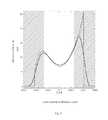
- FIG. 3illustrates a cross section of a simulated ablation profile with the pulse of FIG. 2 in x direction after a 1 st iteration step
- FIG. 4illustrates the simulated ablation profile of FIG. 3 after a 2 nd iteration step
- FIG. 5illustrates a cross section of a simulated ablation profile with the pulse of FIG. 2 in y direction after a 1 st iteration step
- FIG. 6illustrates the simulated ablation profile of FIG. 5 after a 2 nd iteration step
- FIG. 7shows a table with Zernike coefficients relating to the residual wavefront after the 1 st and 2 nd iteration step illustrated in FIGS. 3 to 6 ;
- FIG. 8illustrates a sectional view of a pulse of a single laser shot with a 1.6 mm diameter
- FIG. 9illustrates a cross section of a simulated ablation profile with the pulse of FIG. 8 in x direction after a 1 st iteration step
- FIG. 10illustrates the simulated ablation profile of FIG. 9 after a 2 nd iteration step
- FIG. 11illustrates a cross section of a simulated ablation profile with the pulse of FIG. 8 in y direction after a 1 st iteration step
- FIG. 12illustrates the simulated ablation profile of FIG. 11 after a 2 nd iteration step
- FIG. 13shows a table with Zernike coefficients relating to the residual wavefront after the 1 st and 2 nd iteration step illustrated in FIGS. 9 to 12 ;
- FIG. 14shows a map of the Zernike polynomials notation, the respective sight defect and the Bausch & Lomb notation.
- FIG. 15shows a density plot of the Zernike polynomials up to the seventh order.
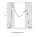
- FIG. 1shows an exemplary wavefront to be corrected with the two different laser pulses.
- the wavefront in FIG. 1is given in a Zernike notation for a pupil radius of 2.5 mm.
- the Zernike coefficientswhich are given in the Bausch & Lomb notation (B&L notation) and the respective vision error, reference is made to FIG. 14 .
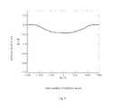
- FIG. 2shows a sectional view of a single laser shot ablation, whereas the laser pulse has a 1.0 mm diameter. More specifically, the ablation depth (y-axis) is shown along a central cross section of the laser pulse. In this example, in the center of the laser pulse which is indicated as 0 ⁇ m on the x-axis there is a maximal ablation depth of about 0.4 ⁇ m. Every laser may have individual pulse characteristics, e.g. asymmetrical, which may change over the life time of the laser.
- the pulse characteristics of a single laser shotmay be measured, e.g., via photo sensitive means or a test shot or a series of test shots in a material which may have at least partially the same characteristics as the material to be ablated based on the obtained laser shot file.
- the test materialmay be polymethyl methacrylate (PMMA).
- PMMApolymethyl methacrylate
- FIG. 3a theoretically determined ablation profile, i.e. a desired ablation profile is illustrated by a dashed line.
- the x-axis of FIG. 3relates to the x direction of the cross section of the ablation and the y-axis relates to the ablation depth.
- the aim of the determination of the laser shot positionsis to come as close as possible or at least up to a predetermined degree to the desired ablation profile.
- the determination of the laser shot positionsis conducted utilizing information about the actually used laser pulse characteristics of a single laser shot.
- the non-shaded portion in FIG. 3relates to the pupil diameter of 5.0 mm, which may be the treatment zone.
- the data produced in the shaded portion which may represent the transition zoneneed not be taken into consideration when determining the laser shot positions in the treatment area.
- a first series of laser shot positionsis calculated based on the desired ablation profile and a simulated ablation profile is generated using said first series of laser shot positions.
- the first series of laser shot positionsmay be based on the extrapolated wavefront as described above.
- the simulation information about one or more pulse characteristics of a single laser shot as illustrated in FIG. 2is used.
- the simulated ablation profile based on the first series of laser shot positions, which corresponds to the 1 st iterationis illustrated in FIG. 3 by the continuous line.
- the simulated ablation profileis compared with the desired ablation profile. Based on the comparison residual structures are determined.
- the first determination of laser shot positions using information about the pulse characteristics of a single laser shotalready provides a result which is quite close to the desired ablation profile in the area of interest, i.e. the pupil area.
- the information relating to the wavefront to be correctedmay be given as a wavefront of nth-order, e.g. 5 th order as in FIG. 1 , and the first series of laser shot positions may be calculated based on said nth-order wavefront.
- the wavefront of the simulated ablation profilemay be added to the wavefront of the desired ablation profile or the Zernike coefficients may be added.
- the addition of the Zernike coefficientsis less complex and may lead to an improved calculation performance.
- nis the order of the wavefront information and ‘iteration_counter’ corresponds to the number of iteration.
- FIGS. 5 and 6show the approximation of the simulated ablation profile in y direction.
- the x-axis in FIGS. 5 and 6relates to the y direction of the cross section of the ablation and the y-axis relates to the ablation depth.
- FIGS. 9 to 12The approximation as shown in FIGS. 9 to 12 is based on the wavefront as given in FIG. 1 , i.e., the desired wavefront (dashed lines) in FIGS. 9 to 12 corresponds to that as illustrated in FIGS. 3 to 6 , respectively.
- the simulated ablation profile (continuous line) of FIG. 9is based on a first series of laser shot positions using information about the pulse characteristics of a single laser shot according to FIG. 8 .
- the simulated ablation profilewith the desired ablation profile (dashed line) residual structures are determined.
- the difference between the simulated ablation profile and the desired ablation profileis greater than that according to corresponding FIG. 3 utilizing the laser pulse having a 1.0 mm diameter.
- Such differencesi.e. the approximation performance, may not only be influenced by laser beam having a different pulse characteristics but also by the utilized dithering algorithm for determining the laser shot positions as well as by the wavefront to be corrected, e.g. having mainly low order aberrations or high order aberrations.
- FIG. 10shows the 2 nd iteration step in x direction corresponding to FIG. 4
- FIGS. 11 and 12correspond to FIGS. 5 and 6 , respectively.
- the present inventioncan be applied to various fields of laser treatments and the figures and the respective description relating to the treatment of an eye is only one example.
- this inventionprovides the base for lasers using large pulse diameters to deliver an ablation profile which is comparable to the results achieved with small spot lasers.
- the inventionis defined by the appended claims and is not limited by the description.
Landscapes
- Health & Medical Sciences (AREA)
- Ophthalmology & Optometry (AREA)
- Physics & Mathematics (AREA)
- Optics & Photonics (AREA)
- Heart & Thoracic Surgery (AREA)
- Animal Behavior & Ethology (AREA)
- Engineering & Computer Science (AREA)
- Biomedical Technology (AREA)
- Nuclear Medicine, Radiotherapy & Molecular Imaging (AREA)
- Vascular Medicine (AREA)
- Life Sciences & Earth Sciences (AREA)
- Surgery (AREA)
- General Health & Medical Sciences (AREA)
- Public Health (AREA)
- Veterinary Medicine (AREA)
- General Physics & Mathematics (AREA)
- Nonlinear Science (AREA)
- Laser Surgery Devices (AREA)
- Laser Beam Processing (AREA)
Abstract
Description
An,mπ
Znπ·m
N′=n−2*iteration_counter.
n is the order of the wavefront information and ‘iteration_counter’ corresponds to the number of iteration.
Claims (13)
N′=n−2*iteration_counter,
Applications Claiming Priority (4)
| Application Number | Priority Date | Filing Date | Title |
|---|---|---|---|
| DE102008053827.2 | 2008-10-30 | ||
| DE102008053827ADE102008053827A1 (en) | 2008-10-30 | 2008-10-30 | Apparatus and method for providing a laser shot file |
| DE102008053827 | 2008-10-30 | ||
| PCT/EP2009/007755WO2010049157A1 (en) | 2008-10-30 | 2009-10-29 | Apparatus and method for providing a laser shot file |
Related Parent Applications (1)
| Application Number | Title | Priority Date | Filing Date |
|---|---|---|---|
| PCT/EP2009/007755ContinuationWO2010049157A1 (en) | 2008-10-30 | 2009-10-29 | Apparatus and method for providing a laser shot file |
Publications (2)
| Publication Number | Publication Date |
|---|---|
| US20110276043A1 US20110276043A1 (en) | 2011-11-10 |
| US9345620B2true US9345620B2 (en) | 2016-05-24 |
Family
ID=41511080
Family Applications (1)
| Application Number | Title | Priority Date | Filing Date |
|---|---|---|---|
| US13/098,267Active2031-07-21US9345620B2 (en) | 2008-10-30 | 2011-04-29 | Apparatus and method for providing a laser shot file |
Country Status (9)
| Country | Link |
|---|---|
| US (1) | US9345620B2 (en) |
| EP (1) | EP2361068B1 (en) |
| KR (1) | KR20110090913A (en) |
| CN (1) | CN102202617A (en) |
| CA (1) | CA2740541A1 (en) |
| DE (1) | DE102008053827A1 (en) |
| ES (1) | ES2550110T3 (en) |
| PL (1) | PL2361068T3 (en) |
| WO (1) | WO2010049157A1 (en) |
Families Citing this family (11)
| Publication number | Priority date | Publication date | Assignee | Title |
|---|---|---|---|---|
| DE102006036085A1 (en)* | 2006-08-02 | 2008-02-07 | Bausch & Lomb Incorporated | Method and apparatus for calculating a laser shot file for use in an excimer laser |
| US20150290032A1 (en)* | 2009-04-06 | 2015-10-15 | Amo Development, Llc | Manifest refraction treatment systems and methods |
| US9642518B2 (en) | 2010-03-30 | 2017-05-09 | Amo Development, Llc | Random eye generation systems and methods |
| US8409178B2 (en)* | 2010-03-30 | 2013-04-02 | Amo Development Llc. | Systems and methods for evaluating treatment tables for refractive surgery |
| US9501621B2 (en) | 2011-03-18 | 2016-11-22 | Amo Development, Llc | Treatment validation systems and methods |
| US9182289B2 (en)* | 2011-10-14 | 2015-11-10 | Canon Kabushiki Kaisha | Apparatus and method for estimating wavefront parameters |
| AU2018215207A1 (en)* | 2017-01-31 | 2019-07-18 | Amo Development, Llc | Methods and systems for laser ophthalmic surgery that provide for iris exposures below a predetermined exposure limit |
| US10857032B2 (en) | 2017-04-11 | 2020-12-08 | Manoj Motwani | Systems and methods for corneal laser ablation |
| US10857033B2 (en) | 2017-05-05 | 2020-12-08 | Manoj Motwani | Systems and methods for corneal laser ablation |
| EP3697356B1 (en)* | 2017-10-17 | 2023-02-15 | Alcon Inc. | Customized ophthalmic surgical profiles |
| CN113974820B (en)* | 2021-09-10 | 2024-09-13 | 周翔 | Simulated ablation method, device, storage medium and equipment based on residual fitting |
Citations (63)
| Publication number | Priority date | Publication date | Assignee | Title |
|---|---|---|---|---|
| US5425727A (en) | 1988-04-01 | 1995-06-20 | Koziol; Jeffrey E. | Beam delivery system and method for corneal surgery |
| WO1995027535A1 (en) | 1994-04-08 | 1995-10-19 | Summit Technology, Inc. | Profiling the intensity distribution of optical beams |
| EP0697611A2 (en) | 1994-08-18 | 1996-02-21 | Carl Zeiss | Optical coherence tomography assisted surgical apparatus |
| WO1996011655A1 (en) | 1994-10-14 | 1996-04-25 | Chiron/Technolas Gmbh Ophthalmologische Systeme | Excimer laser system for correction of vision |
| US5683379A (en)* | 1992-10-01 | 1997-11-04 | Chiron Technolas Gmbh Ophthalmologische Systeme | Apparatus for modifying the surface of the eye through large beam laser polishing and method of controlling the apparatus |
| US5740815A (en)* | 1995-06-07 | 1998-04-21 | Alpins; Noel A. | Method for surgically achieving minimum astigmatism measured refractively and topographically |
| DE19727573C1 (en) | 1996-10-26 | 1998-05-20 | Aesculap Meditec Gmbh | Device and method for shaping surfaces, in particular lenses |
| US5777719A (en) | 1996-12-23 | 1998-07-07 | University Of Rochester | Method and apparatus for improving vision and the resolution of retinal images |
| WO1998048746A1 (en) | 1997-04-25 | 1998-11-05 | Technolas Gmbh Ophthalmologische Systeme | Dual mode ophthalmic laser ablation |
| US5891132A (en)* | 1996-05-30 | 1999-04-06 | Chiron Technolas Gmbh Opthalmologische Systeme | Distributed excimer laser surgery system |
| US5928221A (en) | 1997-11-17 | 1999-07-27 | Coherent, Inc. | Fluence monitoring method for laser treatment of biological tissue |
| US5984916A (en) | 1993-04-20 | 1999-11-16 | Lai; Shui T. | Ophthalmic surgical laser and method |
| US6033075A (en) | 1998-03-31 | 2000-03-07 | Nidek Co., Ltd. | Ophthalmic apparatus |
| US6086204A (en) | 1999-09-20 | 2000-07-11 | Magnante; Peter C. | Methods and devices to design and fabricate surfaces on contact lenses and on corneal tissue that correct the eye's optical aberrations |
| US6129722A (en)* | 1999-03-10 | 2000-10-10 | Ruiz; Luis Antonio | Interactive corrective eye surgery system with topography and laser system interface |
| US6132424A (en) | 1998-03-13 | 2000-10-17 | Lasersight Technologies Inc. | Smooth and uniform laser ablation apparatus and method |
| US6159205A (en) | 1998-09-04 | 2000-12-12 | Sunrise Technologies International Inc. | Radiation treatment method for treating eyes to correct vision |
| WO2001024688A1 (en) | 1999-10-07 | 2001-04-12 | Visx, Inc. | Two camera off-axis eye tracker |
| WO2001028477A1 (en) | 1999-10-21 | 2001-04-26 | Technolas Gmbh Ophthalmologische Systeme | Multi-step laser correction of ophthalmic refractive errors |
| WO2001028410A1 (en) | 1999-10-21 | 2001-04-26 | Technolas Gmbh Ophthalmologische Systeme | Customized corneal profiling |
| US6271936B1 (en) | 1998-12-11 | 2001-08-07 | Eastman Kodak Company | Combining error diffusion, dithering and over-modulation for smooth multilevel printing |
| US6325792B1 (en) | 1991-11-06 | 2001-12-04 | Casimir A. Swinger | Ophthalmic surgical laser and method |
| US6332216B1 (en) | 1999-03-09 | 2001-12-18 | Hewlett-Packard Company | Hybrid just-in-time compiler that consumes minimal resource |
| US20020026180A1 (en) | 2000-08-31 | 2002-02-28 | Nidek Co., Ltd. | Corneal surgery apparatus |
| WO2002034178A1 (en) | 2000-10-20 | 2002-05-02 | Bausch & Lomb Incorporated | Method and system for improving vision |
| US6394999B1 (en) | 2000-03-13 | 2002-05-28 | Memphis Eye & Cataract Associates Ambulatory Surgery Center | Laser eye surgery system using wavefront sensor analysis to control digital micromirror device (DMD) mirror patterns |
| JP2002524144A (en) | 1998-09-04 | 2002-08-06 | サンライズ テクノロジィース インターナショナル インコーポレイテッド | Radiotherapy systems and methods for correcting vision |
| US6454761B1 (en) | 1995-01-30 | 2002-09-24 | Philip D. Freedman | Laser surgery device and method |
| US6511180B2 (en) | 2000-10-10 | 2003-01-28 | University Of Rochester | Determination of ocular refraction from wavefront aberration data and design of optimum customized correction |
| US20030023233A1 (en) | 2001-07-30 | 2003-01-30 | Smith Michael J. | Technique for removal of material to achieve a desired shape with a laser |
| US20030048413A1 (en) | 2001-09-12 | 2003-03-13 | Ross Denwood F. | Ophthalmic wavefront measuring devices |
| US20030128335A1 (en) | 2001-10-15 | 2003-07-10 | Campin John A. | Method for determining accommodation |
| US6607521B2 (en) | 1999-12-09 | 2003-08-19 | Nidek Co., Ltd. | Apparatus for corneal surgery |
| WO2003068103A2 (en) | 2002-02-11 | 2003-08-21 | Visx, Inc. | Closed loop system and method for ablating lenses with aberrations |
| WO2003075778A1 (en) | 2002-03-04 | 2003-09-18 | The Cleveland Clinic Foundation | Method and apparatus for controlling ablation in refractive surgery |
| US20030193647A1 (en) | 2000-02-11 | 2003-10-16 | Neal Daniel R. | Dynamic range extension techniques for a wavefront sensor including use in ophthalmic measurement |
| US20040002697A1 (en) | 2002-06-27 | 2004-01-01 | Gerhard Youssefi | Biconic ablation with controlled spherical aberration |
| US6673062B2 (en)* | 2000-03-14 | 2004-01-06 | Visx, Inc. | Generating scanning spot locations for laser eye surgery |
| US20040021874A1 (en) | 2002-06-27 | 2004-02-05 | Visx, Incorporated, A Delaware Corporation | Integrated scanning and ocular tomography system and method |
| EP1396244A2 (en) | 2002-09-06 | 2004-03-10 | Nidek Co., Ltd. | Corneal-ablation-data calculation apparatus and corneal surgery apparatus |
| US6715877B2 (en) | 2001-03-10 | 2004-04-06 | Vasyl Molebny | Method of measurement of wave aberrations of an eye and device for performing the same |
| WO2004041104A1 (en) | 2002-11-04 | 2004-05-21 | Universita' Degli Studi Di Padova | Laser apparatus for treating hard tissues and method for using the apparatus |
| WO2004053568A1 (en) | 2002-12-06 | 2004-06-24 | Visx, Incorporated | Presbyopia correction using patient data |
| WO2004052253A1 (en) | 2002-11-19 | 2004-06-24 | Carl Zeiss Meditec Ag | Excimer laser unit and relative control method for performing cornea ablation to reduce presbyopia |
| US6755819B1 (en) | 1999-09-10 | 2004-06-29 | Haag-Streit Ag | Method and device for the photoablation of the cornea with a laser beam |
| US6808266B2 (en) | 2001-04-18 | 2004-10-26 | Bausch And Lomb, Inc | Objective manifest refraction |
| WO2004095187A2 (en) | 2003-04-18 | 2004-11-04 | Visx, Incorporated | Systems and methods for correcting high order aberrations in laser refractive surgery |
| WO2005007002A1 (en) | 2003-07-11 | 2005-01-27 | Medizinisches Laserzentrum Luebeck | Method for operation of a laser |
| US6848790B1 (en) | 1999-08-11 | 2005-02-01 | Asclepion-Meditec Ag | Method and device for performing online aberrometrie in refractive eye correction indices |
| US6923802B2 (en) | 2000-03-13 | 2005-08-02 | Memphis Eye & Cataract Assoc. | System for generating ablation profiles for laser refractive eye surgery |
| US20050273088A1 (en) | 2002-06-27 | 2005-12-08 | Gerhard Youssefi | Myopia correction enhancing biodynamic ablation |
| US6997555B2 (en) | 1999-12-03 | 2006-02-14 | Carl Zeiss Meditec Ag | Method for determining vision defects and for collecting data for correcting vision defects of the eye by interaction of a patient with an examiner and apparatus therefor |
| DE202005018911U1 (en) | 2005-06-02 | 2006-03-09 | Wavelight Laser Technologie Ag | Refractive ophthalmology surgery device for correcting defective vision, has two treatment stations in which patient is subjected to different treatments, and couch that is moved from one treatment station to other station |
| DE102005006897A1 (en) | 2005-02-15 | 2006-08-24 | Carl Zeiss Meditec Ag | Ablation program establishing method for correcting ametropia of human eye, involves establishing ablation program based on water concentration of surface to be ablated and pre-compensated set-point ablation profile |
| US7130835B2 (en)* | 2002-03-28 | 2006-10-31 | Bausch & Lomb Incorporated | System and method for predictive ophthalmic correction |
| EP1719483A1 (en) | 2005-05-02 | 2006-11-08 | Cesar C. Dr. Carriazo | Method of controlling a laser for ablating a corneal layer |
| EP1718483A2 (en) | 2004-02-27 | 2006-11-08 | Siemens Aktiengesellschaft | Temperature sensor and arrangement for regulating the climate in the interior of a motor vehicle |
| WO2007012924A1 (en) | 2005-07-26 | 2007-02-01 | 20/10 Perfect Vision Ag | System and method for compensating a corneal dissection |
| WO2007143111A2 (en) | 2006-06-01 | 2007-12-13 | University Of Southern California | Method and apparatus to guide laser corneal surgery with optical measurement |
| US20080033408A1 (en)* | 2006-07-19 | 2008-02-07 | Michael Bueler | Computer program for ophthalmological surgery |
| US20080058780A1 (en) | 2006-08-07 | 2008-03-06 | Wavelight Ag | Laser System for Refractive Surgery |
| US7380942B2 (en) | 2002-10-04 | 2008-06-03 | Sergiy Molebny | Method for measuring the wave aberrations of the eye |
| US20090264874A1 (en)* | 2006-08-02 | 2009-10-22 | Ernst Hegels | Method and apparatus for calculating a laser shot file for use in a refractive excimer laser |
Family Cites Families (2)
| Publication number | Priority date | Publication date | Assignee | Title |
|---|---|---|---|---|
| DE102004033819B8 (en)* | 2004-07-13 | 2011-11-10 | Wavelight Gmbh | Method for generating control data of a laser system for ophthalmological procedures |
| DE102005006879B4 (en)* | 2005-02-14 | 2007-07-19 | LAUKÖTTER, Karl-Heinz | Pistons for working or power machines |
- 2008
- 2008-10-30DEDE102008053827Apatent/DE102008053827A1/ennot_activeCeased
- 2009
- 2009-10-29CACA2740541Apatent/CA2740541A1/ennot_activeAbandoned
- 2009-10-29PLPL09760715Tpatent/PL2361068T3/enunknown
- 2009-10-29CNCN2009801435690Apatent/CN102202617A/enactivePending
- 2009-10-29ESES09760715.4Tpatent/ES2550110T3/enactiveActive
- 2009-10-29WOPCT/EP2009/007755patent/WO2010049157A1/enactiveApplication Filing
- 2009-10-29EPEP09760715.4Apatent/EP2361068B1/enactiveActive
- 2009-10-29KRKR1020117010007Apatent/KR20110090913A/ennot_activeWithdrawn
- 2011
- 2011-04-29USUS13/098,267patent/US9345620B2/enactiveActive
Patent Citations (75)
| Publication number | Priority date | Publication date | Assignee | Title |
|---|---|---|---|---|
| US5425727A (en) | 1988-04-01 | 1995-06-20 | Koziol; Jeffrey E. | Beam delivery system and method for corneal surgery |
| US6325792B1 (en) | 1991-11-06 | 2001-12-04 | Casimir A. Swinger | Ophthalmic surgical laser and method |
| US5683379A (en)* | 1992-10-01 | 1997-11-04 | Chiron Technolas Gmbh Ophthalmologische Systeme | Apparatus for modifying the surface of the eye through large beam laser polishing and method of controlling the apparatus |
| US6090100A (en) | 1992-10-01 | 2000-07-18 | Chiron Technolas Gmbh Ophthalmologische Systeme | Excimer laser system for correction of vision with reduced thermal effects |
| US5984916A (en) | 1993-04-20 | 1999-11-16 | Lai; Shui T. | Ophthalmic surgical laser and method |
| WO1995027535A1 (en) | 1994-04-08 | 1995-10-19 | Summit Technology, Inc. | Profiling the intensity distribution of optical beams |
| EP0697611A2 (en) | 1994-08-18 | 1996-02-21 | Carl Zeiss | Optical coherence tomography assisted surgical apparatus |
| US6635051B1 (en) | 1994-10-14 | 2003-10-21 | Technolas Gmbh Ophthalmologische Systeme | Excimer laser system for correction of vision with reduced thermal effects |
| WO1996011655A1 (en) | 1994-10-14 | 1996-04-25 | Chiron/Technolas Gmbh Ophthalmologische Systeme | Excimer laser system for correction of vision |
| US6454761B1 (en) | 1995-01-30 | 2002-09-24 | Philip D. Freedman | Laser surgery device and method |
| US5740815A (en)* | 1995-06-07 | 1998-04-21 | Alpins; Noel A. | Method for surgically achieving minimum astigmatism measured refractively and topographically |
| US5891132A (en)* | 1996-05-30 | 1999-04-06 | Chiron Technolas Gmbh Opthalmologische Systeme | Distributed excimer laser surgery system |
| US6139542A (en)* | 1996-05-30 | 2000-10-31 | Chiron Technolas Gmbh Opthalmologische Systeme | Distributed excimer laser surgery system |
| DE19727573C1 (en) | 1996-10-26 | 1998-05-20 | Aesculap Meditec Gmbh | Device and method for shaping surfaces, in particular lenses |
| US5949521A (en) | 1996-12-23 | 1999-09-07 | University Of Rochester | Method and apparatus for improving vision and the resolution of retinal images |
| US6095651A (en) | 1996-12-23 | 2000-08-01 | University Of Rochester | Method and apparatus for improving vision and the resolution of retinal images |
| US5777719A (en) | 1996-12-23 | 1998-07-07 | University Of Rochester | Method and apparatus for improving vision and the resolution of retinal images |
| WO1998048746A1 (en) | 1997-04-25 | 1998-11-05 | Technolas Gmbh Ophthalmologische Systeme | Dual mode ophthalmic laser ablation |
| US5928221A (en) | 1997-11-17 | 1999-07-27 | Coherent, Inc. | Fluence monitoring method for laser treatment of biological tissue |
| US6132424A (en) | 1998-03-13 | 2000-10-17 | Lasersight Technologies Inc. | Smooth and uniform laser ablation apparatus and method |
| US6033075A (en) | 1998-03-31 | 2000-03-07 | Nidek Co., Ltd. | Ophthalmic apparatus |
| JP2002524144A (en) | 1998-09-04 | 2002-08-06 | サンライズ テクノロジィース インターナショナル インコーポレイテッド | Radiotherapy systems and methods for correcting vision |
| US6159205A (en) | 1998-09-04 | 2000-12-12 | Sunrise Technologies International Inc. | Radiation treatment method for treating eyes to correct vision |
| US6271936B1 (en) | 1998-12-11 | 2001-08-07 | Eastman Kodak Company | Combining error diffusion, dithering and over-modulation for smooth multilevel printing |
| US6332216B1 (en) | 1999-03-09 | 2001-12-18 | Hewlett-Packard Company | Hybrid just-in-time compiler that consumes minimal resource |
| US20020075451A1 (en) | 1999-03-10 | 2002-06-20 | Ruiz Luis Antonio | Interactive corrective eye surgery system with topography and laser system interface |
| JP2000300596A (en) | 1999-03-10 | 2000-10-31 | Antonio Louiz Louis | Interface device for providing eye reshaping data, method of operating the same for generating data used in eye reshaping device |
| US6129722A (en)* | 1999-03-10 | 2000-10-10 | Ruiz; Luis Antonio | Interactive corrective eye surgery system with topography and laser system interface |
| US20050159733A1 (en) | 1999-08-11 | 2005-07-21 | Asclepion Meditec Ag | Method and device for performing online aberrometry in refractive eye correction |
| US6848790B1 (en) | 1999-08-11 | 2005-02-01 | Asclepion-Meditec Ag | Method and device for performing online aberrometrie in refractive eye correction indices |
| US6755819B1 (en) | 1999-09-10 | 2004-06-29 | Haag-Streit Ag | Method and device for the photoablation of the cornea with a laser beam |
| US6086204A (en) | 1999-09-20 | 2000-07-11 | Magnante; Peter C. | Methods and devices to design and fabricate surfaces on contact lenses and on corneal tissue that correct the eye's optical aberrations |
| WO2001024688A1 (en) | 1999-10-07 | 2001-04-12 | Visx, Inc. | Two camera off-axis eye tracker |
| WO2001028410A1 (en) | 1999-10-21 | 2001-04-26 | Technolas Gmbh Ophthalmologische Systeme | Customized corneal profiling |
| WO2001028477A1 (en) | 1999-10-21 | 2001-04-26 | Technolas Gmbh Ophthalmologische Systeme | Multi-step laser correction of ophthalmic refractive errors |
| US6997555B2 (en) | 1999-12-03 | 2006-02-14 | Carl Zeiss Meditec Ag | Method for determining vision defects and for collecting data for correcting vision defects of the eye by interaction of a patient with an examiner and apparatus therefor |
| US6607521B2 (en) | 1999-12-09 | 2003-08-19 | Nidek Co., Ltd. | Apparatus for corneal surgery |
| US20030193647A1 (en) | 2000-02-11 | 2003-10-16 | Neal Daniel R. | Dynamic range extension techniques for a wavefront sensor including use in ophthalmic measurement |
| US6500171B1 (en) | 2000-03-13 | 2002-12-31 | Memphis Eye & Cataract Associates Ambulatory Surgery Center | System for generating ablation profiles for laser refractive eye surgery |
| US6923802B2 (en) | 2000-03-13 | 2005-08-02 | Memphis Eye & Cataract Assoc. | System for generating ablation profiles for laser refractive eye surgery |
| US6394999B1 (en) | 2000-03-13 | 2002-05-28 | Memphis Eye & Cataract Associates Ambulatory Surgery Center | Laser eye surgery system using wavefront sensor analysis to control digital micromirror device (DMD) mirror patterns |
| US6508812B1 (en) | 2000-03-13 | 2003-01-21 | Memphis Eye & Cataract Associates Ambulatory Surgery Center | Control system for high resolution high speed digital micromirror device for laser refractive eye surgery |
| US6413251B1 (en)* | 2000-03-13 | 2002-07-02 | Memphis Eye & Cataract Associates Ambulatory Surgery Center | Method and system for controlling a digital mircomirror device for laser refractive eye surgery |
| US6673062B2 (en)* | 2000-03-14 | 2004-01-06 | Visx, Inc. | Generating scanning spot locations for laser eye surgery |
| US20020026180A1 (en) | 2000-08-31 | 2002-02-28 | Nidek Co., Ltd. | Corneal surgery apparatus |
| US6511180B2 (en) | 2000-10-10 | 2003-01-28 | University Of Rochester | Determination of ocular refraction from wavefront aberration data and design of optimum customized correction |
| WO2002034178A1 (en) | 2000-10-20 | 2002-05-02 | Bausch & Lomb Incorporated | Method and system for improving vision |
| US20020082629A1 (en) | 2000-10-20 | 2002-06-27 | Bausch & Lomb Incorporated | Method and system for improving vision |
| US6715877B2 (en) | 2001-03-10 | 2004-04-06 | Vasyl Molebny | Method of measurement of wave aberrations of an eye and device for performing the same |
| US6808266B2 (en) | 2001-04-18 | 2004-10-26 | Bausch And Lomb, Inc | Objective manifest refraction |
| US20030023233A1 (en) | 2001-07-30 | 2003-01-30 | Smith Michael J. | Technique for removal of material to achieve a desired shape with a laser |
| US20030048413A1 (en) | 2001-09-12 | 2003-03-13 | Ross Denwood F. | Ophthalmic wavefront measuring devices |
| US20030128335A1 (en) | 2001-10-15 | 2003-07-10 | Campin John A. | Method for determining accommodation |
| WO2003068103A2 (en) | 2002-02-11 | 2003-08-21 | Visx, Inc. | Closed loop system and method for ablating lenses with aberrations |
| WO2003075778A1 (en) | 2002-03-04 | 2003-09-18 | The Cleveland Clinic Foundation | Method and apparatus for controlling ablation in refractive surgery |
| US7130835B2 (en)* | 2002-03-28 | 2006-10-31 | Bausch & Lomb Incorporated | System and method for predictive ophthalmic correction |
| US20040002697A1 (en) | 2002-06-27 | 2004-01-01 | Gerhard Youssefi | Biconic ablation with controlled spherical aberration |
| US20050273088A1 (en) | 2002-06-27 | 2005-12-08 | Gerhard Youssefi | Myopia correction enhancing biodynamic ablation |
| US20040021874A1 (en) | 2002-06-27 | 2004-02-05 | Visx, Incorporated, A Delaware Corporation | Integrated scanning and ocular tomography system and method |
| EP1396244A2 (en) | 2002-09-06 | 2004-03-10 | Nidek Co., Ltd. | Corneal-ablation-data calculation apparatus and corneal surgery apparatus |
| US7380942B2 (en) | 2002-10-04 | 2008-06-03 | Sergiy Molebny | Method for measuring the wave aberrations of the eye |
| WO2004041104A1 (en) | 2002-11-04 | 2004-05-21 | Universita' Degli Studi Di Padova | Laser apparatus for treating hard tissues and method for using the apparatus |
| WO2004052253A1 (en) | 2002-11-19 | 2004-06-24 | Carl Zeiss Meditec Ag | Excimer laser unit and relative control method for performing cornea ablation to reduce presbyopia |
| WO2004053568A1 (en) | 2002-12-06 | 2004-06-24 | Visx, Incorporated | Presbyopia correction using patient data |
| WO2004095187A2 (en) | 2003-04-18 | 2004-11-04 | Visx, Incorporated | Systems and methods for correcting high order aberrations in laser refractive surgery |
| WO2005007002A1 (en) | 2003-07-11 | 2005-01-27 | Medizinisches Laserzentrum Luebeck | Method for operation of a laser |
| EP1718483A2 (en) | 2004-02-27 | 2006-11-08 | Siemens Aktiengesellschaft | Temperature sensor and arrangement for regulating the climate in the interior of a motor vehicle |
| DE102005006897A1 (en) | 2005-02-15 | 2006-08-24 | Carl Zeiss Meditec Ag | Ablation program establishing method for correcting ametropia of human eye, involves establishing ablation program based on water concentration of surface to be ablated and pre-compensated set-point ablation profile |
| EP1719483A1 (en) | 2005-05-02 | 2006-11-08 | Cesar C. Dr. Carriazo | Method of controlling a laser for ablating a corneal layer |
| DE202005018911U1 (en) | 2005-06-02 | 2006-03-09 | Wavelight Laser Technologie Ag | Refractive ophthalmology surgery device for correcting defective vision, has two treatment stations in which patient is subjected to different treatments, and couch that is moved from one treatment station to other station |
| WO2007012924A1 (en) | 2005-07-26 | 2007-02-01 | 20/10 Perfect Vision Ag | System and method for compensating a corneal dissection |
| WO2007143111A2 (en) | 2006-06-01 | 2007-12-13 | University Of Southern California | Method and apparatus to guide laser corneal surgery with optical measurement |
| US20080033408A1 (en)* | 2006-07-19 | 2008-02-07 | Michael Bueler | Computer program for ophthalmological surgery |
| US20090264874A1 (en)* | 2006-08-02 | 2009-10-22 | Ernst Hegels | Method and apparatus for calculating a laser shot file for use in a refractive excimer laser |
| US20080058780A1 (en) | 2006-08-07 | 2008-03-06 | Wavelight Ag | Laser System for Refractive Surgery |
Non-Patent Citations (3)
| Title |
|---|
| Damien Gatinel, et al., "Three-dimensional representation and qualitative comparisons of the amount of tissue ablation to treat mixed and compound astigmatism," Journal of Cataract and Refractive Surgery, vol. 28 (No. 11), p. 2026-2034 (Nov. 1, 2002). |
| PCT International Search Report regarding U.S. Appl. No. 13/098,267; International Application No. PCT/EP2009/007755; International Filing Date: Oct. 29, 2009; Priority Date: Oct. 30, 2008 for Applicant Technolas Perfect Vision GmbH. |
| U.S. 5,423,802, Jun. 13, 1995, Marshall. |
Also Published As
| Publication number | Publication date |
|---|---|
| WO2010049157A1 (en) | 2010-05-06 |
| KR20110090913A (en) | 2011-08-10 |
| CA2740541A1 (en) | 2010-05-06 |
| EP2361068B1 (en) | 2015-10-07 |
| EP2361068A1 (en) | 2011-08-31 |
| ES2550110T3 (en) | 2015-11-04 |
| US20110276043A1 (en) | 2011-11-10 |
| CN102202617A (en) | 2011-09-28 |
| PL2361068T3 (en) | 2016-03-31 |
| DE102008053827A1 (en) | 2010-05-12 |
Similar Documents
| Publication | Publication Date | Title |
|---|---|---|
| US9345620B2 (en) | Apparatus and method for providing a laser shot file | |
| JP4430847B2 (en) | Generation of scan spot positions for laser eye surgery | |
| AU2008251316B2 (en) | Combined wavefront and topography systems and methods | |
| JP3615487B2 (en) | Offset ablation profile for treatment of irregular astigmatism | |
| CN100403998C (en) | Closed loop system and method for ablating an aberrated lens | |
| JP5016307B2 (en) | Iterative Fourier reconstruction for laser surgery and other optical applications | |
| US20090160075A1 (en) | Methods for fabricating customized intraocular lenses | |
| EP2552370B1 (en) | System and method for evaluating treatment tables for refractive surgery | |
| US20230372154A1 (en) | Method for providing control data for a laser of a treatment apparatus | |
| JP2011518028A (en) | Higher order optical correction during corneal laser surgery | |
| CN114343967B (en) | Method for providing control data for an ophthalmic surgical laser of a treatment device, control device and treatment device | |
| US8709002B2 (en) | Ophthalmic system for shape determination and modification | |
| US20090264874A1 (en) | Method and apparatus for calculating a laser shot file for use in a refractive excimer laser | |
| US20210361487A1 (en) | Method for providing control data for an eye surgical laser of a treatment apparatus | |
| US20250041119A1 (en) | Method for providing control data for an ophthalmological laser of a treatment apparatus | |
| US9916423B2 (en) | Random eye generation systems and methods | |
| CN118203470A (en) | Method for providing deformation correction control data for a laser of a treatment device | |
| Osipova et al. | Eye micromotions influence on an error of Zernike coefficients reconstruction in the one-ray refractometry of an eye |
Legal Events
| Date | Code | Title | Description |
|---|---|---|---|
| AS | Assignment | Owner name:BARCLAYS BANK PLC, AS COLLATERAL AGENT, NEW YORK Free format text:SECURITY AGREEMENT;ASSIGNORS:TECHNOLAS PERFECT VISION GMBH;DR. GERHARD MANN CHEM-PHARM. FABRIK GMBH;REEL/FRAME:036400/0711 Effective date:20150819 | |
| STCF | Information on status: patent grant | Free format text:PATENTED CASE | |
| AS | Assignment | Owner name:THE BANK OF NEW YORK MELLON, NEW YORK Free format text:SECURITY INTEREST;ASSIGNOR:TECHNOLAS PERFECT VISION GMBH;REEL/FRAME:043251/0910 Effective date:20170717 | |
| AS | Assignment | Owner name:THE BANK OF NEW YORK MELLON, AS COLLATERAL AGENT, NEW YORK Free format text:SECURITY INTEREST;ASSIGNORS:ATON PHARMA, INC.;BAUSCH & LOMB INCORPORATED;BAUSCH & LOMB PHARMA HOLDINGS CORP.;AND OTHERS;REEL/FRAME:045444/0634 Effective date:20180213 Owner name:BARCLAYS BANK PLC, AS COLLATERAL AGENT, NEW YORK Free format text:SECURITY INTEREST;ASSIGNORS:ATON PHARMA, INC.;BAUSCH & LOMB INCORPORATED;BAUSCH & LOMB PHARMA HOLDINGS CORP.;AND OTHERS;REEL/FRAME:045444/0299 Effective date:20180213 Owner name:THE BANK OF NEW YORK MELLON, AS COLLATERAL AGENT, Free format text:SECURITY INTEREST;ASSIGNORS:ATON PHARMA, INC.;BAUSCH & LOMB INCORPORATED;BAUSCH & LOMB PHARMA HOLDINGS CORP.;AND OTHERS;REEL/FRAME:045444/0634 Effective date:20180213 | |
| AS | Assignment | Owner name:THE BANK OF NEW YORK MELLON, AS COLLATERAL AGENT, Free format text:INTELLECTUAL PROPERTY SECURITY AGREEMENT;ASSIGNORS:BAUSCH HEALTH IRELAND LIMITED;BAUSCH HEALTH COMPANIES INC.;BAUSCH HEALTH, CANADA INC.;AND OTHERS;REEL/FRAME:049672/0652 Effective date:20190701 Owner name:THE BANK OF NEW YORK MELLON, AS COLLATERAL AGENT, NEW YORK Free format text:INTELLECTUAL PROPERTY SECURITY AGREEMENT;ASSIGNORS:BAUSCH HEALTH IRELAND LIMITED;BAUSCH HEALTH COMPANIES INC.;BAUSCH HEALTH, CANADA INC.;AND OTHERS;REEL/FRAME:049672/0652 Effective date:20190701 | |
| MAFP | Maintenance fee payment | Free format text:PAYMENT OF MAINTENANCE FEE, 4TH YEAR, LARGE ENTITY (ORIGINAL EVENT CODE: M1551); ENTITY STATUS OF PATENT OWNER: LARGE ENTITY Year of fee payment:4 | |
| AS | Assignment | Owner name:THE BANK OF NEW YORK MELLON, AS NOTES COLLATERAL AGENT, NEW YORK Free format text:SECURITY INTEREST;ASSIGNORS:BAUSCH & LOMB IRELAND LIMITED;BAUSCH HEALTH COMPANIES INC.;DR. GERHARD MANN CHEM.-PHARM. FABRIK GMBH;AND OTHERS;REEL/FRAME:057821/0800 Effective date:20211004 | |
| AS | Assignment | Owner name:TECHNOLAS PERFECT VISION GMBH, GERMANY Free format text:RELEASE OF SECURITY INTEREST IN SPECIFIED PATENTS (REEL/FRAME 036400/0711);ASSIGNOR:BARCLAYS BANK PLC;REEL/FRAME:061775/0826 Effective date:20221019 Owner name:BAUSCH & LOMB INCORPORATED, NEW YORK Free format text:RELEASE OF SECURITY INTEREST IN SPECIFIED PATENTS (REEL/FRAME 036400/0711);ASSIGNOR:BARCLAYS BANK PLC;REEL/FRAME:061775/0826 Effective date:20221019 Owner name:LABORATOIRE CHAUVIN S.A.S., FRANCE Free format text:RELEASE OF SECURITY INTEREST IN SPECIFIED PATENTS (REEL/FRAME 045444/0299);ASSIGNOR:BARCLAYS BANK PLC;REEL/FRAME:061779/0001 Effective date:20221019 Owner name:PF CONSUMER HEALTHCARE 1 LLC, DELAWARE Free format text:RELEASE OF SECURITY INTEREST IN SPECIFIED PATENTS (REEL/FRAME 045444/0299);ASSIGNOR:BARCLAYS BANK PLC;REEL/FRAME:061779/0001 Effective date:20221019 Owner name:THE UNITED STATES OF AMERICA, AS REPRESENTED BY THE SECRETARY, DEPARTMENT OF HEALTH AND HUMAN SERVICES, MARYLAND Free format text:RELEASE OF SECURITY INTEREST IN SPECIFIED PATENTS (REEL/FRAME 045444/0299);ASSIGNOR:BARCLAYS BANK PLC;REEL/FRAME:061779/0001 Effective date:20221019 Owner name:TECHNOLAS PERFECT VISION GMBH, GERMANY Free format text:RELEASE OF SECURITY INTEREST IN SPECIFIED PATENTS (REEL/FRAME 045444/0299);ASSIGNOR:BARCLAYS BANK PLC;REEL/FRAME:061779/0001 Effective date:20221019 Owner name:BAUSCH & LOMB INCORPORATED, NEW YORK Free format text:RELEASE OF SECURITY INTEREST IN SPECIFIED PATENTS (REEL/FRAME 045444/0299);ASSIGNOR:BARCLAYS BANK PLC;REEL/FRAME:061779/0001 Effective date:20221019 | |
| AS | Assignment | Owner name:THE UNITED STATES OF AMERICA, AS REPRESENTED BY THE SECRETARY, DEPARTMENT OF HEALTH AND HUMAN SERVICES, MARYLAND Free format text:OMNIBUS PATENT SECURITY RELEASE AGREEMENT (REEL/FRAME 045444/0634);ASSIGNOR:THE BANK OF NEW YORK MELLON;REEL/FRAME:061872/0295 Effective date:20221018 Owner name:TECHNOLAS PERFECT VISION GMBH, GERMANY Free format text:OMNIBUS PATENT SECURITY RELEASE AGREEMENT (REEL/FRAME 045444/0634);ASSIGNOR:THE BANK OF NEW YORK MELLON;REEL/FRAME:061872/0295 Effective date:20221018 Owner name:LABORATOIRE CHAUVIN S.A.S., FRANCE Free format text:OMNIBUS PATENT SECURITY RELEASE AGREEMENT (REEL/FRAME 045444/0634);ASSIGNOR:THE BANK OF NEW YORK MELLON;REEL/FRAME:061872/0295 Effective date:20221018 Owner name:BAUSCH & LOMB INCORPORATED, NEW YORK Free format text:OMNIBUS PATENT SECURITY RELEASE AGREEMENT (REEL/FRAME 045444/0634);ASSIGNOR:THE BANK OF NEW YORK MELLON;REEL/FRAME:061872/0295 Effective date:20221018 Owner name:BAUSCH + LOMB IRELAND LIMITED, IRELAND Free format text:OMNIBUS PATENT SECURITY RELEASE AGREEMENT (REEL/FRAME 057821/0800);ASSIGNOR:THE BANK OF NEW YORK MELLON;REEL/FRAME:061884/0514 Effective date:20221018 Owner name:TECHNOLAS PERFECT VISION GMBH, GERMANY Free format text:OMNIBUS PATENT SECURITY RELEASE AGREEMENT (REEL/FRAME 057821/0800);ASSIGNOR:THE BANK OF NEW YORK MELLON;REEL/FRAME:061884/0514 Effective date:20221018 | |
| MAFP | Maintenance fee payment | Free format text:PAYMENT OF MAINTENANCE FEE, 8TH YEAR, LARGE ENTITY (ORIGINAL EVENT CODE: M1552); ENTITY STATUS OF PATENT OWNER: LARGE ENTITY Year of fee payment:8 |