US9345231B2 - Selective access control apparatus for animals using electronic recognition - Google Patents
Selective access control apparatus for animals using electronic recognitionDownload PDFInfo
- Publication number
- US9345231B2 US9345231B2US14/090,853US201314090853AUS9345231B2US 9345231 B2US9345231 B2US 9345231B2US 201314090853 AUS201314090853 AUS 201314090853AUS 9345231 B2US9345231 B2US 9345231B2
- Authority
- US
- United States
- Prior art keywords
- tag
- animal
- antenna
- antennas
- access
- Prior art date
- Legal status (The legal status is an assumption and is not a legal conclusion. Google has not performed a legal analysis and makes no representation as to the accuracy of the status listed.)
- Active, expires
Links
- 241001465754MetazoaSpecies0.000titleclaimsabstractdescription96
- 230000005540biological transmissionEffects0.000claimsabstractdescription21
- 238000013459approachMethods0.000claimsabstractdescription11
- 230000008878couplingEffects0.000claimsdescription4
- 238000010168coupling processMethods0.000claimsdescription4
- 238000005859coupling reactionMethods0.000claimsdescription4
- 230000001939inductive effectEffects0.000claimsdescription3
- 238000001514detection methodMethods0.000claimsdescription2
- 238000000034methodMethods0.000abstractdescription16
- 238000005516engineering processMethods0.000description7
- 230000004044responseEffects0.000description7
- 238000004891communicationMethods0.000description5
- 230000035945sensitivityEffects0.000description2
- 229910000859α-FeInorganic materials0.000description2
- 208000019901Anxiety diseaseDiseases0.000description1
- 238000010521absorption reactionMethods0.000description1
- 239000000654additiveSubstances0.000description1
- 230000000996additive effectEffects0.000description1
- 230000036506anxietyEffects0.000description1
- 238000013475authorizationMethods0.000description1
- 125000004122cyclic groupChemical group0.000description1
- 238000013461designMethods0.000description1
- 230000001066destructive effectEffects0.000description1
- 238000011161developmentMethods0.000description1
- 238000010586diagramMethods0.000description1
- 230000000694effectsEffects0.000description1
- 230000005684electric fieldEffects0.000description1
- 238000001914filtrationMethods0.000description1
- 230000037406food intakeEffects0.000description1
- 235000012631food intakeNutrition0.000description1
- 230000003993interactionEffects0.000description1
- 238000007726management methodMethods0.000description1
- 238000004519manufacturing processMethods0.000description1
- 239000002184metalSubstances0.000description1
- 238000012986modificationMethods0.000description1
- 230000004048modificationEffects0.000description1
- 230000000737periodic effectEffects0.000description1
- 230000008707rearrangementEffects0.000description1
- 230000001360synchronised effectEffects0.000description1
- 230000008685targetingEffects0.000description1
- XLYOFNOQVPJJNP-UHFFFAOYSA-NwaterSubstancesOXLYOFNOQVPJJNP-UHFFFAOYSA-N0.000description1
Images


Classifications
- A—HUMAN NECESSITIES
- A01—AGRICULTURE; FORESTRY; ANIMAL HUSBANDRY; HUNTING; TRAPPING; FISHING
- A01K—ANIMAL HUSBANDRY; AVICULTURE; APICULTURE; PISCICULTURE; FISHING; REARING OR BREEDING ANIMALS, NOT OTHERWISE PROVIDED FOR; NEW BREEDS OF ANIMALS
- A01K5/00—Feeding devices for stock or game ; Feeding wagons; Feeding stacks
- A01K5/02—Automatic devices
- A—HUMAN NECESSITIES
- A01—AGRICULTURE; FORESTRY; ANIMAL HUSBANDRY; HUNTING; TRAPPING; FISHING
- A01K—ANIMAL HUSBANDRY; AVICULTURE; APICULTURE; PISCICULTURE; FISHING; REARING OR BREEDING ANIMALS, NOT OTHERWISE PROVIDED FOR; NEW BREEDS OF ANIMALS
- A01K11/00—Marking of animals
- A01K11/006—Automatic identification systems for animals, e.g. electronic devices, transponders for animals
- A—HUMAN NECESSITIES
- A01—AGRICULTURE; FORESTRY; ANIMAL HUSBANDRY; HUNTING; TRAPPING; FISHING
- A01K—ANIMAL HUSBANDRY; AVICULTURE; APICULTURE; PISCICULTURE; FISHING; REARING OR BREEDING ANIMALS, NOT OTHERWISE PROVIDED FOR; NEW BREEDS OF ANIMALS
- A01K5/00—Feeding devices for stock or game ; Feeding wagons; Feeding stacks
- A01K5/01—Feed troughs; Feed pails
- A01K5/0114—Pet food dispensers; Pet food trays
- A01K5/0142—Pet food dispensers; Pet food trays with means for preventing other animals or insects from eating
- A—HUMAN NECESSITIES
- A01—AGRICULTURE; FORESTRY; ANIMAL HUSBANDRY; HUNTING; TRAPPING; FISHING
- A01K—ANIMAL HUSBANDRY; AVICULTURE; APICULTURE; PISCICULTURE; FISHING; REARING OR BREEDING ANIMALS, NOT OTHERWISE PROVIDED FOR; NEW BREEDS OF ANIMALS
- A01K5/00—Feeding devices for stock or game ; Feeding wagons; Feeding stacks
- A01K5/02—Automatic devices
- A01K5/025—Automatic devices with doors or lids activated by the animals to access feeding place or trough
- G07C9/00111—
- G—PHYSICS
- G07—CHECKING-DEVICES
- G07C—TIME OR ATTENDANCE REGISTERS; REGISTERING OR INDICATING THE WORKING OF MACHINES; GENERATING RANDOM NUMBERS; VOTING OR LOTTERY APPARATUS; ARRANGEMENTS, SYSTEMS OR APPARATUS FOR CHECKING NOT PROVIDED FOR ELSEWHERE
- G07C9/00—Individual registration on entry or exit
- G07C9/20—Individual registration on entry or exit involving the use of a pass
- G07C9/28—Individual registration on entry or exit involving the use of a pass the pass enabling tracking or indicating presence
Definitions
- the present inventionrelates to methods and systems for providing controlled access to various different locations and/or objects. More specifically, the present invention relates to an automated system whereby animals are tagged with an ID device are reliably and consistently allowed access to various locations and/or objects, such as food contained within a food delivery device dish for example.
- RFID systemsare also well understood for use in large area and or large number of animals or objects. In order to meet the needs of large area coverage with consistent performance, these systems include multiple and diversely located antennas powerful transceivers and complex communication methods resulting in a very high cost system. Therefore there is a need for a system which is simple and low cost with an RFID system built into a unitary structure that can identify and manage the unique needs of multiple animal interaction with objects such as feeding devices, litter boxes, waterers, toys and other objects which an animal may interact with.
- RFIDradio frequency identification
- the present inventionrelates generally to an improved radio frequency identification (RFID) system. More specifically, the present invention relates to a RFID access control system that reliably operates at a well defined medium range and low power in contrast to prior art RFID systems.
- RFID applicationsgenerally operate in very short or very long range arrangements because the requirements for reliable communication at distances of about 3 feet is not something that the larger RFID industry has had to create operational system for.
- existing RFID applicationsare focused at either operational ranges of below 6 inches range or up to a hundred feet or more.
- RFID systems with stringent functional requirements that operate between about 6 inches to about 3 feetare higher in cost and typically utilized in industrial applications.
- the RFIDIn certain controlled access systems that rely in RFID, the RFID must be consistently read so that the product responds the same each time regardless of time of day, temperature in the room proximity to appliances either on or off. If the response is not consistent in an animal access system for example, then the animal will get mixed signals when trying to eat or not be allowed to eat. Inconsistency will cause problems for the animals. For example if an animal that is tagged to allow access to a food delivery device finds that sometimes it gets access and sometimes it does not then it will become confused and or aggravated and develop anxiety and further eating issues when the goal is to reduce eating issues. In a further example, if an animal is locked out of one food delivery device learns that it can occasionally beat the system because the system does not always sense it fast enough, it will keep trying to steal food. Conversely, if the system works nearly all the time then the animal will realize there is no reward and stop trying to steal food from that food delivery device and focus on the one to which it allowed access.
- the systemin contrast to much of the prior art, the system must function in near to 100% of the covered space around the food delivery device (or other product) at a very high level of reliability, because if there is a null or dead zone resulting from poor antenna arrangement or nearness of a dish washer or other metal appliance which reflects the signal in a way not intended by the designer. The animal may find this poor coverage area and learn it can sneak up on the system and therefore steal food. Again once this happens it will continue to do this which reduces the effectiveness of the product.
- the RFID systemmust have sufficient range to allow the system to sense the animal approaching and open early enough so as not to make the animal wait for the food, but even more important again the system must sense the aggressive animal that is not supposed to get to the food in that food delivery device and close before it can steal the food.
- the RFID systemmust not have too much range or it will sense animals that are waiting away from either their food delivery device or the one they are locked out of, or perhaps just walking by. If the food delivery device senses these tags outside of the immediate space around the food delivery device then it may cause problems for the animal that is eating at the food delivery device by the door closing then opening then closing.
- the present inventionprovides a method and system provided that controls access to various different locations and/or objects. More specifically, in a preferred embodiment, the present invention provides an automated system whereby animals are tagged with an ID device are reliably and consistently allowed access to various locations and/or objects, such as food contained within a food delivery device dish for example.
- the present inventionis disclosed a powered RFID tag, such as battery assisted, solar powered, or other system that stores electrical energy within the tag making it internally powered.
- An alternative tag embodimentconsiders the tag to be powered, however the power is generated from a received signal when the tag receives a transmission from the feeder.
- the tagemploys inductive or H field coupled resonance RFID transmissions. In such a system several frequency options are possible and may be selected based on country RF codes and or on frequencies which are not often used in a household environment.
- a high sensitivity receiveremploys a multiple antenna array that is shielded against receiving electric field energy but instead uses magnetic field coupling with an active RFID tag for receiving its transmissions.
- the antenna arraycovers all possible animal approach directions for a range of up to 36′′, but not more.
- the antenna arraymay also be located entirely in the body of the product.
- the systememploys a signal identification and filtering protocol that works with short duration ( ⁇ 20 msec) transmission times and pulsed transmissions at less than 2 second intervals.
- the receiver and tagboth employ wire wound receiving/transmitting antennas.
- the tagmay employ a ferrite core transmitting antenna.
- a possible additionwould be the use of an accelerometer to maximize tag battery life and to randomize the start of the tag's message response, as to not having to transmit when an animal is in rest (sleeping and the like).
- H-field coupled RFID and antenna shieldingis employed.
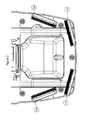
- FIG. 1is a front perspective view of an animal feeding dish in accordance with the teachings of the present invention
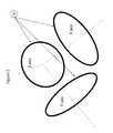
- FIG. 2is a perspective view showing a 3 antenna array where each antenna is aligned to one of each of a 3 dimensional axis system;
- FIG. 3is a top view of the antenna of an animal feeding dish
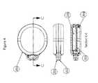
- FIG. 4is a grouping of tag views including a section view
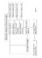
- FIG. 5is a flow chart of one mode for antenna scanning and selection logic
- FIG. 6is a flow chart of an alternative mode for antenna scanning and selection logic
- FIG. 7is a schematic view of a typical power filter circuit.
- a method and systemthat controls animal access to various different locations and/or objects and more specifically, in the preferred embodiment, provides an automated system whereby animals wearing an authorized ID tag are allowed access to various locations and/or objects, such as food contained within a food delivery device dish for example, Animals wearing a non-authorized ID tag causes the device to close preventing access thereto by the animal(s).
- a systemfor controlling animal access to locations or objects.
- the systemincludes a location or object to be controlled, a means for preventing animal access to said location or object and a sensor system configured and arranged to selectively disengage the means for preventing animal access.
- the sensor systemincludes at least one active tag that provides authorization to access the location or object wherein the at least one tag is preferably disposed on an authorized animal, a first sensor for controlling animal access by detecting, through H-field coupling RF communication, the presence of the tag and disengaging the means for preventing animal access and further detecting the presence of an animal other than the authorized animal and engaging the means for preventing animal access.
- FIG. 1specifically illustrates an animal food delivery device 10 .
- the food delivery device 10can be seen to include a housing 12 that includes a compartment 16 therein and electronics 18 for controlling the overall system.
- a base portion 14covers the antenna array as shown in FIG. 3 .
- FIG. 2one embodiment employs a multiple antenna array that has one antenna aligned to each axis of a standard 3 dimensional set of orthogonal set of axes.
- This antenna array and connected receiveris combined with RFID tagging FIG. 4 for a rapid response and well defined range system.
- a long life battery assisted tagmay be in any orientation and location within 3 feet of the device, but the low power RFID signal must be received with very high reliability to ensure that the system responds in a consistently repeatable manner so as not to confuse/frustrate the animal.
- a custom low cost systemhas been developed whereby an antenna array is incorporated to reliably cover the three dimensional space that the tag 200 will appear in when an animal approaches the object.
- an antenna arrayis provided.
- an antennais placed in each of three orthogonal planes in three dimensional space.
- the antennas 100 , 101 , 102 , 103are oriented to best detect the directions which an animal approaches the food delivery device, i.e. biased vertically and towards the front and forward sides of the food delivery device.
- the antenna arrayemploys 2, 3 or four antennas arranged where at least 2 are close to orthogonal angles to one another.
- an arrayis provided consisting of at least 2 antennas where an included angle between them is of not less than 60 degrees and not more than 120 degrees.
- the antennasmay be wire wound, ferrite core, or on a printed circuit board.
- the present inventiondeploys a lower RF frequency and inductive or H-field coupling between the tag and antenna array. Once frequencies enter the VHF range, RF energy has issues with being absorbed by living tissue due to the high water content of such tissue. Deploying lower frequency H-field communication (near field) solves the problem of tissue absorption. H-field communication also provides better control over the range of operation of the device.
- H-field signalsdecay at 1 over the cube of the distance as compared to RF which decays at 1 over the square of the distance thereby giving a much more finite control over the range of the system to protect against false detections resulting in a well defined range of functionality targeted for up to 3 feet from the product.
- a well understood filter methodsuch as that shown in FIG. 7 may prevent line noise from entering the system.
- the purpose of this filteris to attenuate noise conducted along the wires from the power supply to the food delivery device.
- This noisecan be from either a wall adapter and its cord, an AC power line to which the wall adapter is connected or from nearby radiating noise sources that create antenna noise current in the power wiring, which could also include power wiring from a battery power supply located either internal or external to the product.
- a multipoint background noise level filtergoing on and updating the background noise level all the time such that an incoming transmission is more readily identified.
- FIG. 4one embodiment of the tag of this system can be seen 200 .
- the enclosures 201 and 202enclose and protect the power source sown as a coin cell 205 typical of small low power devices, and the tag board 203 and coil antenna 204 .
- the systemmay operate in one of two ways, (1) the tag is transmitting at a periodic time all the time, perhaps at less than 2 seconds intervals and the receiver in the food delivery device simply listens, or (2) the tag is quiet until receiving a wakeup call from a base transceiver in the food delivery device at which point the tag responds and transmits periodically as defined above until the animal is out of the transmission range at which point it goes quiet again.
- the wakeup callmay also provide the energy to power the tags transmission.
- Tag transmissionshave been designed to each have different interval timing between responses to prevent multiple tags from “synchronized colliding” with each other, which would be a possibility if each tag had a fixed wait time.
- the wait time between tagsis randomized by component uncertainty in the watch dog timer, as well as a deliberately programmed randomization in the tag response timing derived from the five LSB bits as present in the tag's unique Id field, yielding 32 different variations in tag response time.
- the tag's response timingis also randomized by the uncertainty for the tag wakeup once the tag's accelerometer has been activated.
- a tagis established as authorized or non-authorized at initial set up of the logic system.
- the logic for one embodimentis as follows, the receiver system is listening at each antenna for short durations by switching through each antenna individually for less than a millisecond each. The system temporarily stores the reception level energy of the received signal for each antenna. (It is subsequently overwritten by the next time based energy level for that antenna). In either case, when there is reception of signal above the background level by a certain predetermined amount the system evaluates the recorded energy level for each antenna in the array.
- the systemdetermines if the tag is authorized. If an authorized tag is present, the door opens to allow the animal access to the food contained therein. The system evaluates that signal level by the logic. In doing so the system scans during the transmission preamble targeting the antennas having good reception signal strength. In this way the reception energy is used to target and select an optimum reception situation. Once the best option antenna is established the system switches to that antenna, leaving all other antennas in the array and receives the balance of the signal from that best option antenna. The system then confirms if the transmission is a valid or non-valid transmission and if the tag is accepted or rejected
- the systemchecks for an entire tag message per antenna scan interval.
- the received tag messageis then validated by the system by matching the tag message CRC (Cyclic Redundancy Check) with the actual received tag data. If found OK by the reader software (meaning the tag message was received without errors), the particular received tag message is then stored by the system.
- the antenna scanning dwell timeis extended to at least one message duration to guarantee detecting the start of a message and to remain there until at least one full message is received before switching to the next antenna (which is dictated by the asynchronous nature between actual antenna scan interval and the start of the tag transmission).
- One method for the logic for progression in this alternative embodimentis shown in the event flow diagram in FIG. 6 .
- FIG. 7illustrates the shorter duration message.
- the extended dwell timecan be tailored to either receive a certain number of messages and switch to the next antenna or to read the maximum number of messages per transmission burst.
- the system softwarecan then determine at which antenna the tag was read the most (by doing a tag read tally per antenna). This antenna will then have a high probability of being the one to which the particular tag is the closest in terms of vicinity and that way have a high reliability of receiving the transmissions.
- the systemis therefore optimized to make the best use of a very low power system for maximum sensitivity while also requiring the cost and complexity of only one receiver.
- the tagsends its transmitted message at intervals of less than 2 seconds for a duration of less than 20 ms as a combination of items in a predetermined order.
- the transmissionis first the preamble which is what the receiver uses to identify power level and ideal antenna.
- the systemcould transmit the amount of time an animal was active and or the time/intensity of activity as picked up by the accelerometer in the tag currently used to shut off the tag when the animal is inactive to save on battery life. It should be mentioned, that the transmission time frame is preferably less than 20 ms and is more preferably less than 10 ms.
- the present inventionprovides an automatic system that provides selective control and access to other various locations and objects such as animal related items like food delivery devices, litter boxes, animal watering systems including circulating and outside of the house non circulating, animal toys, animal crate and gate access, animal doors, animal beds, and animal containment systems in a relatively less complex and cost-effective in regard to its use and operation.
- animal related itemslike food delivery devices, litter boxes, animal watering systems including circulating and outside of the house non circulating, animal toys, animal crate and gate access, animal doors, animal beds, and animal containment systems in a relatively less complex and cost-effective in regard to its use and operation.
- animal related itemslike food delivery devices, litter boxes, animal watering systems including circulating and outside of the house non circulating, animal toys, animal crate and gate access, animal doors, animal beds, and animal containment systems in a relatively less complex and cost-effective in regard to its use and operation.
- animal containment systemsin a relatively less complex and cost-effective in regard to its use and operation.
Landscapes
- Life Sciences & Earth Sciences (AREA)
- Environmental Sciences (AREA)
- Animal Husbandry (AREA)
- Biodiversity & Conservation Biology (AREA)
- Birds (AREA)
- Zoology (AREA)
- Physics & Mathematics (AREA)
- General Physics & Mathematics (AREA)
- Housing For Livestock And Birds (AREA)
- Radar Systems Or Details Thereof (AREA)
- Near-Field Transmission Systems (AREA)
- Catching Or Destruction (AREA)
- Feeding And Watering For Cattle Raising And Animal Husbandry (AREA)
- Animal Behavior & Ethology (AREA)
Abstract
Description
Claims (15)
Priority Applications (9)
| Application Number | Priority Date | Filing Date | Title |
|---|---|---|---|
| US14/090,853US9345231B2 (en) | 2013-11-26 | 2013-11-26 | Selective access control apparatus for animals using electronic recognition |
| EP14865497.3AEP3073819A4 (en) | 2013-11-26 | 2014-11-26 | Access control for animals using electronic recognition |
| AU2014354706AAU2014354706B2 (en) | 2013-11-26 | 2014-11-26 | Access control for animals using electronic recognition |
| BR112016012040ABR112016012040A2 (en) | 2013-11-26 | 2014-11-26 | ACCESS CONTROL FOR ANIMALS USING ELECTRONIC RECOGNITION |
| PCT/US2014/067701WO2015081252A1 (en) | 2013-11-26 | 2014-11-26 | Access control for animals using electronic recognition |
| CA2931621ACA2931621C (en) | 2013-11-26 | 2014-11-26 | Access control for animals using electronic recognition |
| CN201480071086.5ACN105934152A (en) | 2013-11-26 | 2014-11-26 | Animal access control using electronic identification |
| US14/558,065US20150143750A1 (en) | 2013-11-26 | 2014-12-02 | Method and system for providing preidentified pets selective access to a predetermined location or object |
| CL2016001290ACL2016001290A1 (en) | 2013-11-26 | 2016-05-26 | Access control device for animals using electronic recognition. |
Applications Claiming Priority (1)
| Application Number | Priority Date | Filing Date | Title |
|---|---|---|---|
| US14/090,853US9345231B2 (en) | 2013-11-26 | 2013-11-26 | Selective access control apparatus for animals using electronic recognition |
Related Child Applications (1)
| Application Number | Title | Priority Date | Filing Date |
|---|---|---|---|
| US14/558,065Continuation-In-PartUS20150143750A1 (en) | 2013-11-26 | 2014-12-02 | Method and system for providing preidentified pets selective access to a predetermined location or object |
Publications (2)
| Publication Number | Publication Date |
|---|---|
| US20150145644A1 US20150145644A1 (en) | 2015-05-28 |
| US9345231B2true US9345231B2 (en) | 2016-05-24 |
Family
ID=53182162
Family Applications (1)
| Application Number | Title | Priority Date | Filing Date |
|---|---|---|---|
| US14/090,853Active2034-02-03US9345231B2 (en) | 2013-11-26 | 2013-11-26 | Selective access control apparatus for animals using electronic recognition |
Country Status (8)
| Country | Link |
|---|---|
| US (1) | US9345231B2 (en) |
| EP (1) | EP3073819A4 (en) |
| CN (1) | CN105934152A (en) |
| AU (1) | AU2014354706B2 (en) |
| BR (1) | BR112016012040A2 (en) |
| CA (1) | CA2931621C (en) |
| CL (1) | CL2016001290A1 (en) |
| WO (1) | WO2015081252A1 (en) |
Cited By (18)
| Publication number | Priority date | Publication date | Assignee | Title |
|---|---|---|---|---|
| USD812501S1 (en)* | 2016-10-10 | 2018-03-13 | Petpomm, Inc. | Pet monitoring base station |
| US10085419B2 (en)* | 2015-07-13 | 2018-10-02 | C-Lock Inc. | Modular livestock feed system for measuring animal intake and monitoring animal health |
| USD885686S1 (en)* | 2019-01-21 | 2020-05-26 | Dogness Group LLC | Pet feeder |
| USD885685S1 (en)* | 2019-01-21 | 2020-05-26 | Dogness Group LLC | Pet feeder |
| USD891004S1 (en)* | 2018-12-26 | 2020-07-21 | Amy Park | Pet feeder |
| USD893109S1 (en)* | 2019-04-27 | 2020-08-11 | Rensong Zeng | Automatic food feeder for animals |
| USD897609S1 (en)* | 2017-08-23 | 2020-09-29 | Mars, Incorporated | Pet food dispenser |
| USD920592S1 (en)* | 2019-08-22 | 2021-05-25 | Wei Tang | Automatic feeding device for animals |
| USD921117S1 (en)* | 2020-07-30 | 2021-06-01 | Jinhao Chen | Board game |
| USD963256S1 (en)* | 2021-06-04 | 2022-09-06 | Fan Lin | Automatic pet feeder |
| USD983463S1 (en)* | 2022-12-14 | 2023-04-11 | Fuzhou Boweier Trading Co., Ltd. | Pet feeder |
| USD989411S1 (en)* | 2023-04-06 | 2023-06-13 | Shenzhen Shouzheng Chuqi Technology Co., Ltd. | Pet feeder |
| USD1002957S1 (en)* | 2021-07-05 | 2023-10-24 | Chengying Yu | Automatic feeding device for pets |
| USD1027321S1 (en)* | 2022-09-05 | 2024-05-14 | Chengying Yu | Animal feeder |
| USD1029406S1 (en)* | 2023-02-15 | 2024-05-28 | Th Products, Llc | Pet feeder |
| USD1067533S1 (en) | 2023-06-20 | 2025-03-18 | Th Products, Llc | Pet feeder |
| USD1084532S1 (en)* | 2023-09-06 | 2025-07-15 | Shenzhen Libro Technology Co., Ltd. | Pet feeder |
| US12433248B2 (en) | 2023-02-14 | 2025-10-07 | Th Products, Llc | Smart pet feeder |
Families Citing this family (12)
| Publication number | Priority date | Publication date | Assignee | Title |
|---|---|---|---|---|
| FR3016229B1 (en) | 2014-01-07 | 2016-02-05 | Systemes Et Technologies Identification Stid | ACCESS CONTROL READER AND COMPLEMENTARY CONTROL MODULE |
| FR3016228B1 (en)* | 2014-01-07 | 2016-02-05 | Systemes Et Technologies Identification Stid | ACCESS CONTROL READER WITH OPENING DETECTION DEVICE |
| US10292363B2 (en)* | 2015-02-10 | 2019-05-21 | Harold G Monk | Species specific feeder |
| USD771878S1 (en)* | 2015-09-28 | 2016-11-15 | Petkit Network Technology (Shanghai) Co., Ltd. | Intelligent antibacterial bowl |
| JP6714726B2 (en)* | 2016-11-24 | 2020-06-24 | シャープ株式会社 | Individual specifying device, individual specifying system, control method of individual specifying device, and control program |
| USD846815S1 (en)* | 2017-01-15 | 2019-04-23 | Kofi Darkwah | Pet water dispenser with integrated standard one gallon water jug chamber |
| USD836850S1 (en)* | 2017-06-05 | 2018-12-25 | Guangdong Cuter Pet Technology Co., Ltd. | Automatic pet feeder |
| USD889049S1 (en)* | 2019-01-24 | 2020-06-30 | Dogness Group LLC | Pet bowl |
| USD945081S1 (en)* | 2020-01-21 | 2022-03-01 | Kind Pet Products Co., Ltd | Automatic pet feeder |
| CN111328729A (en)* | 2020-04-21 | 2020-06-26 | 上海联宠智能科技有限公司 | Cat intelligence is fed and is eaten device |
| EP3996425A1 (en)* | 2020-11-05 | 2022-05-11 | Nxp B.V. | Rf communication devices and operating methods |
| USD1036789S1 (en)* | 2022-03-21 | 2024-07-23 | Pluto Opco (Cayman), Llc | Feeder |
Citations (17)
| Publication number | Priority date | Publication date | Assignee | Title |
|---|---|---|---|---|
| DE2302885A1 (en) | 1973-01-20 | 1974-08-01 | Bifora Uhren | AUTOMATIC WINDING FOR THE SPRING OF A SMALL CLOCK |
| US5992096A (en)* | 1998-10-19 | 1999-11-30 | Pooch Pass, Inc. | Controllable pet access system |
| US6025783A (en) | 1998-04-30 | 2000-02-15 | Trw Vehicle Safety Systems Inc. | Wireless switch detection system |
| US6700547B2 (en)* | 2002-04-12 | 2004-03-02 | Digital Angel Corporation | Multidirectional walkthrough antenna |
| US7349772B2 (en) | 2004-12-16 | 2008-03-25 | International Truck Intellectual Property Company, Llc | Vehicle integrated radio remote control |
| WO2008108816A1 (en) | 2007-03-05 | 2008-09-12 | Fort Supply Ip, Llc | System and method for subject management using intelligent rf tag and reader |
| US7458336B2 (en)* | 2005-05-07 | 2008-12-02 | Philip Stephen Eu | Animal identification and entry control system for feeding purposes |
| US7477758B2 (en) | 1992-05-05 | 2009-01-13 | Automotive Technologies International, Inc. | System and method for detecting objects in vehicular compartments |
| US20090315704A1 (en) | 2008-06-19 | 2009-12-24 | Global Biomedical Development, Llc, A Georgia Limited Liability Company | Method and Integrated System for Tracking Luggage |
| US7786864B1 (en) | 2000-09-08 | 2010-08-31 | Automotive Technologies International, Inc. | Vehicular RFID and sensor assemblies |
| US7889096B2 (en) | 2000-09-08 | 2011-02-15 | Automotive Technologies International, Inc. | Vehicular component control using wireless switch assemblies |
| US20110254665A1 (en) | 2004-04-30 | 2011-10-20 | Binforma Group Limited Liability Company | Reversibly deactivating a radio frequency identification data tag |
| US20110252684A1 (en) | 2008-02-27 | 2011-10-20 | Robert Ufer | Self calibrating weapon shot counter |
| US20120092157A1 (en) | 2005-10-16 | 2012-04-19 | Bao Tran | Personal emergency response (per) system |
| US20120139729A1 (en) | 2008-03-17 | 2012-06-07 | Chris Savarese | Golf club apparatuses and methods |
| EP2574023A1 (en) | 2011-09-23 | 2013-03-27 | Research In Motion Limited | Mobile wireless communications device for near field communication (nfc) operations and related power savings method |
| US8930148B2 (en)* | 2010-10-07 | 2015-01-06 | Growsafe Systems Ltd. | Animal identification, measurement, monitoring and management system |
Family Cites Families (15)
| Publication number | Priority date | Publication date | Assignee | Title |
|---|---|---|---|---|
| US5653192A (en)* | 1996-03-06 | 1997-08-05 | Alfa Laval Agri Inc. | Livestock identification apparatus |
| US6297734B1 (en)* | 1999-09-23 | 2001-10-02 | Northrop Grumman Corporation | Randomization of transmit time |
| US6396438B1 (en)* | 1999-09-24 | 2002-05-28 | Slc Technologies | System and method for locating radio frequency identification tags using three-phase antenna |
| US6833790B2 (en) | 2002-04-12 | 2004-12-21 | Digital Angel Corporation | Livestock chute scanner |
| GB0221887D0 (en)* | 2002-09-20 | 2002-10-30 | Shearwell Data Ltd | Detection and identification of animals |
| CN101421744B (en)* | 2004-11-08 | 2013-06-05 | 依德西亚有限公司 | Electro-biometric identification methods and devices |
| GB2431431B (en)* | 2005-10-22 | 2010-05-19 | Pet Mate Ltd | Pet door |
| US20070152831A1 (en)* | 2006-01-05 | 2007-07-05 | Sean Eisele | 3-axis RFID tag antenna |
| WO2007131839A1 (en)* | 2006-05-15 | 2007-11-22 | International Business Machines Corporation | METHOD AND SYSTEMS FOR LOCALIZING OBJECTS USING PASSIVE RFID TAGs |
| US20080074271A1 (en)* | 2006-09-27 | 2008-03-27 | Science Applications International Corporation | Radio frequency transponders having three-dimensional antennas |
| GB0619489D0 (en)* | 2006-10-03 | 2006-11-08 | Hill Nicholas P R | RFID pet door |
| US8219053B2 (en)* | 2007-10-19 | 2012-07-10 | Destron Fearing Corporation | Automatic tuning reader |
| FI123146B (en) | 2009-10-01 | 2012-11-30 | Bayer Schering Pharma Oy | An intrauterine system |
| CA2799568C (en)* | 2010-05-18 | 2014-12-09 | Woodstream Corporation | Custom-shape wireless dog fence system and method |
| GB2498346B (en)* | 2012-01-10 | 2016-01-06 | Pet Mate Ltd | Pet door systems and methods of operation thereof |
- 2013
- 2013-11-26USUS14/090,853patent/US9345231B2/enactiveActive
- 2014
- 2014-11-26BRBR112016012040Apatent/BR112016012040A2/ennot_activeApplication Discontinuation
- 2014-11-26EPEP14865497.3Apatent/EP3073819A4/ennot_activeWithdrawn
- 2014-11-26AUAU2014354706Apatent/AU2014354706B2/enactiveActive
- 2014-11-26CACA2931621Apatent/CA2931621C/enactiveActive
- 2014-11-26CNCN201480071086.5Apatent/CN105934152A/enactivePending
- 2014-11-26WOPCT/US2014/067701patent/WO2015081252A1/enactiveApplication Filing
- 2016
- 2016-05-26CLCL2016001290Apatent/CL2016001290A1/enunknown
Patent Citations (17)
| Publication number | Priority date | Publication date | Assignee | Title |
|---|---|---|---|---|
| DE2302885A1 (en) | 1973-01-20 | 1974-08-01 | Bifora Uhren | AUTOMATIC WINDING FOR THE SPRING OF A SMALL CLOCK |
| US7477758B2 (en) | 1992-05-05 | 2009-01-13 | Automotive Technologies International, Inc. | System and method for detecting objects in vehicular compartments |
| US6025783A (en) | 1998-04-30 | 2000-02-15 | Trw Vehicle Safety Systems Inc. | Wireless switch detection system |
| US5992096A (en)* | 1998-10-19 | 1999-11-30 | Pooch Pass, Inc. | Controllable pet access system |
| US7786864B1 (en) | 2000-09-08 | 2010-08-31 | Automotive Technologies International, Inc. | Vehicular RFID and sensor assemblies |
| US7889096B2 (en) | 2000-09-08 | 2011-02-15 | Automotive Technologies International, Inc. | Vehicular component control using wireless switch assemblies |
| US6700547B2 (en)* | 2002-04-12 | 2004-03-02 | Digital Angel Corporation | Multidirectional walkthrough antenna |
| US20110254665A1 (en) | 2004-04-30 | 2011-10-20 | Binforma Group Limited Liability Company | Reversibly deactivating a radio frequency identification data tag |
| US7349772B2 (en) | 2004-12-16 | 2008-03-25 | International Truck Intellectual Property Company, Llc | Vehicle integrated radio remote control |
| US7458336B2 (en)* | 2005-05-07 | 2008-12-02 | Philip Stephen Eu | Animal identification and entry control system for feeding purposes |
| US20120092157A1 (en) | 2005-10-16 | 2012-04-19 | Bao Tran | Personal emergency response (per) system |
| WO2008108816A1 (en) | 2007-03-05 | 2008-09-12 | Fort Supply Ip, Llc | System and method for subject management using intelligent rf tag and reader |
| US20110252684A1 (en) | 2008-02-27 | 2011-10-20 | Robert Ufer | Self calibrating weapon shot counter |
| US20120139729A1 (en) | 2008-03-17 | 2012-06-07 | Chris Savarese | Golf club apparatuses and methods |
| US20090315704A1 (en) | 2008-06-19 | 2009-12-24 | Global Biomedical Development, Llc, A Georgia Limited Liability Company | Method and Integrated System for Tracking Luggage |
| US8930148B2 (en)* | 2010-10-07 | 2015-01-06 | Growsafe Systems Ltd. | Animal identification, measurement, monitoring and management system |
| EP2574023A1 (en) | 2011-09-23 | 2013-03-27 | Research In Motion Limited | Mobile wireless communications device for near field communication (nfc) operations and related power savings method |
Non-Patent Citations (3)
| Title |
|---|
| Cho et al., "An NFC transceiver using an inductive powered receiver for passive, active, RW and RFID modes," SoC Design Conference (ISOCC), 2009 International, 2009, pp. 456, 459, 22-24. |
| Meng et al., "Design of Low-Power Active RFID Tag in UHF Bank," Control, Automation and Systems Engineering (CASE), 2011 International Conference on, 2011, pp. 1,4,30-31. |
| Raphaeli, D. et al., "UWB Communication System with Pulse Interleaving Multiple Access for Active RFID", Microwaves, Communications, Antennas and Electronics Systems, 2009. COMCAS 2009. IEEE International Conference on, 2009, pp. 1, 5, 9-11. |
Cited By (18)
| Publication number | Priority date | Publication date | Assignee | Title |
|---|---|---|---|---|
| US10085419B2 (en)* | 2015-07-13 | 2018-10-02 | C-Lock Inc. | Modular livestock feed system for measuring animal intake and monitoring animal health |
| USD812501S1 (en)* | 2016-10-10 | 2018-03-13 | Petpomm, Inc. | Pet monitoring base station |
| USD897609S1 (en)* | 2017-08-23 | 2020-09-29 | Mars, Incorporated | Pet food dispenser |
| USD891004S1 (en)* | 2018-12-26 | 2020-07-21 | Amy Park | Pet feeder |
| USD885686S1 (en)* | 2019-01-21 | 2020-05-26 | Dogness Group LLC | Pet feeder |
| USD885685S1 (en)* | 2019-01-21 | 2020-05-26 | Dogness Group LLC | Pet feeder |
| USD893109S1 (en)* | 2019-04-27 | 2020-08-11 | Rensong Zeng | Automatic food feeder for animals |
| USD920592S1 (en)* | 2019-08-22 | 2021-05-25 | Wei Tang | Automatic feeding device for animals |
| USD921117S1 (en)* | 2020-07-30 | 2021-06-01 | Jinhao Chen | Board game |
| USD963256S1 (en)* | 2021-06-04 | 2022-09-06 | Fan Lin | Automatic pet feeder |
| USD1002957S1 (en)* | 2021-07-05 | 2023-10-24 | Chengying Yu | Automatic feeding device for pets |
| USD1027321S1 (en)* | 2022-09-05 | 2024-05-14 | Chengying Yu | Animal feeder |
| USD983463S1 (en)* | 2022-12-14 | 2023-04-11 | Fuzhou Boweier Trading Co., Ltd. | Pet feeder |
| US12433248B2 (en) | 2023-02-14 | 2025-10-07 | Th Products, Llc | Smart pet feeder |
| USD1029406S1 (en)* | 2023-02-15 | 2024-05-28 | Th Products, Llc | Pet feeder |
| USD989411S1 (en)* | 2023-04-06 | 2023-06-13 | Shenzhen Shouzheng Chuqi Technology Co., Ltd. | Pet feeder |
| USD1067533S1 (en) | 2023-06-20 | 2025-03-18 | Th Products, Llc | Pet feeder |
| USD1084532S1 (en)* | 2023-09-06 | 2025-07-15 | Shenzhen Libro Technology Co., Ltd. | Pet feeder |
Also Published As
| Publication number | Publication date |
|---|---|
| CL2016001290A1 (en) | 2016-12-02 |
| US20150145644A1 (en) | 2015-05-28 |
| CA2931621A1 (en) | 2015-06-04 |
| CA2931621C (en) | 2018-06-19 |
| WO2015081252A1 (en) | 2015-06-04 |
| EP3073819A1 (en) | 2016-10-05 |
| AU2014354706B2 (en) | 2017-04-06 |
| AU2014354706A1 (en) | 2016-06-23 |
| EP3073819A4 (en) | 2017-07-12 |
| BR112016012040A2 (en) | 2017-08-08 |
| CN105934152A (en) | 2016-09-07 |
Similar Documents
| Publication | Publication Date | Title |
|---|---|---|
| US9345231B2 (en) | Selective access control apparatus for animals using electronic recognition | |
| US7583931B2 (en) | Animal identification and entry control system | |
| US7458336B2 (en) | Animal identification and entry control system for feeding purposes | |
| CN1145128C (en) | Low-power radio frequency identification reader | |
| EP2080172B1 (en) | Rfid pet door | |
| AU2005307747B2 (en) | Radio frequency animal tracking system | |
| US7685966B2 (en) | Lidded pet dish | |
| US20020134313A1 (en) | System, method, and apparatus for controlling animal feeding | |
| US20100147226A1 (en) | Interactive Pet Accessories | |
| US9715777B2 (en) | RFID pet door | |
| US20070103314A1 (en) | Radio frequency animal tracking system | |
| JP2002543646A5 (en) | ||
| EP0125287A1 (en) | IDENTIFICATION SYSTEM. | |
| US20040222645A1 (en) | Magnetic lock device operated by means of transponder | |
| US20070103315A1 (en) | Flexible animal tag, printing system, and methods | |
| GB2483551A (en) | Animal access system |
Legal Events
| Date | Code | Title | Description |
|---|---|---|---|
| AS | Assignment | Owner name:VET INNOVATIONS, LLC, A LIMITED LIABILITY COMPANY, Free format text:ASSIGNMENT OF ASSIGNORS INTEREST;ASSIGNORS:JALBERT, DAVID B.;SAAR, DAVID;EAKER, DIANE;SIGNING DATES FROM 20131125 TO 20131126;REEL/FRAME:031685/0369 | |
| STCF | Information on status: patent grant | Free format text:PATENTED CASE | |
| AS | Assignment | Owner name:VET INNOVATIONS, INC., CONNECTICUT Free format text:NUNC PRO TUNC ASSIGNMENT;ASSIGNOR:VET INNOVATIONS, LLC;REEL/FRAME:048737/0653 Effective date:20190329 | |
| AS | Assignment | Owner name:NINGBO FUJIA INDUSTRIAL CO., LTD., MASSACHUSETTS Free format text:SECURITY INTEREST;ASSIGNOR:VET INNOVATIONS, INC.;REEL/FRAME:048842/0926 Effective date:20190410 Owner name:SINGAPORE LEADER ELECTRIC APPLIANCE PTE, LTD., MAS Free format text:SECURITY INTEREST;ASSIGNOR:VET INNOVATIONS, INC.;REEL/FRAME:048842/0837 Effective date:20190410 | |
| MAFP | Maintenance fee payment | Free format text:PAYMENT OF MAINTENANCE FEE, 4TH YR, SMALL ENTITY (ORIGINAL EVENT CODE: M2551); ENTITY STATUS OF PATENT OWNER: SMALL ENTITY Year of fee payment:4 | |
| AS | Assignment | Owner name:AMERICAN LEADER ELECTRIC APPLIANCE, INC., MASSACHU Free format text:ASSIGNMENT OF INTELLECTUAL PROPERTY SECURITY AGREEMENT;ASSIGNOR:SINGAPORE LEADER ELECTRIC APPLIANCE PTE, LTD.;REEL/FRAME:051445/0137 Effective date:20191230 | |
| AS | Assignment | Owner name:AMERICA LEADER ELECTRIC APPLIANCE INC., MASSACHUSETTS Free format text:ASSIGNMENT OF ASSIGNORS INTEREST;ASSIGNOR:VET INNOVATIONS, INC.;REEL/FRAME:055945/0491 Effective date:20210412 | |
| MAFP | Maintenance fee payment | Free format text:PAYMENT OF MAINTENANCE FEE, 8TH YR, SMALL ENTITY (ORIGINAL EVENT CODE: M2552); ENTITY STATUS OF PATENT OWNER: SMALL ENTITY Year of fee payment:8 |