US9343248B2 - Systems and methods for implementing spring loaded mechanical key switches with variable displacement sensing - Google Patents
Systems and methods for implementing spring loaded mechanical key switches with variable displacement sensingDownload PDFInfo
- Publication number
- US9343248B2 US9343248B2US14/013,724US201314013724AUS9343248B2US 9343248 B2US9343248 B2US 9343248B2US 201314013724 AUS201314013724 AUS 201314013724AUS 9343248 B2US9343248 B2US 9343248B2
- Authority
- US
- United States
- Prior art keywords
- key
- depressable
- key switch
- key component
- displacement
- Prior art date
- Legal status (The legal status is an assumption and is not a legal conclusion. Google has not performed a legal analysis and makes no representation as to the accuracy of the status listed.)
- Active, expires
Links
Images


Classifications
- H—ELECTRICITY
- H01—ELECTRIC ELEMENTS
- H01H—ELECTRIC SWITCHES; RELAYS; SELECTORS; EMERGENCY PROTECTIVE DEVICES
- H01H13/00—Switches having rectilinearly-movable operating part or parts adapted for pushing or pulling in one direction only, e.g. push-button switch
- H01H13/70—Switches having rectilinearly-movable operating part or parts adapted for pushing or pulling in one direction only, e.g. push-button switch having a plurality of operating members associated with different sets of contacts, e.g. keyboard
- H01H13/702—Switches having rectilinearly-movable operating part or parts adapted for pushing or pulling in one direction only, e.g. push-button switch having a plurality of operating members associated with different sets of contacts, e.g. keyboard with contacts carried by or formed from layers in a multilayer structure, e.g. membrane switches
- H01H13/705—Switches having rectilinearly-movable operating part or parts adapted for pushing or pulling in one direction only, e.g. push-button switch having a plurality of operating members associated with different sets of contacts, e.g. keyboard with contacts carried by or formed from layers in a multilayer structure, e.g. membrane switches characterised by construction, mounting or arrangement of operating parts, e.g. push-buttons or keys
- H01H13/7065—Switches having rectilinearly-movable operating part or parts adapted for pushing or pulling in one direction only, e.g. push-button switch having a plurality of operating members associated with different sets of contacts, e.g. keyboard with contacts carried by or formed from layers in a multilayer structure, e.g. membrane switches characterised by construction, mounting or arrangement of operating parts, e.g. push-buttons or keys characterised by the mechanism between keys and layered keyboards
- H01H13/7073—Switches having rectilinearly-movable operating part or parts adapted for pushing or pulling in one direction only, e.g. push-button switch having a plurality of operating members associated with different sets of contacts, e.g. keyboard with contacts carried by or formed from layers in a multilayer structure, e.g. membrane switches characterised by construction, mounting or arrangement of operating parts, e.g. push-buttons or keys characterised by the mechanism between keys and layered keyboards characterised by springs, e.g. Euler springs
- G—PHYSICS
- G06—COMPUTING OR CALCULATING; COUNTING
- G06F—ELECTRIC DIGITAL DATA PROCESSING
- G06F3/00—Input arrangements for transferring data to be processed into a form capable of being handled by the computer; Output arrangements for transferring data from processing unit to output unit, e.g. interface arrangements
- G06F3/01—Input arrangements or combined input and output arrangements for interaction between user and computer
- G06F3/02—Input arrangements using manually operated switches, e.g. using keyboards or dials
- G06F3/0202—Constructional details or processes of manufacture of the input device
- G—PHYSICS
- G06—COMPUTING OR CALCULATING; COUNTING
- G06F—ELECTRIC DIGITAL DATA PROCESSING
- G06F3/00—Input arrangements for transferring data to be processed into a form capable of being handled by the computer; Output arrangements for transferring data from processing unit to output unit, e.g. interface arrangements
- G06F3/01—Input arrangements or combined input and output arrangements for interaction between user and computer
- G06F3/02—Input arrangements using manually operated switches, e.g. using keyboards or dials
- G06F3/0227—Cooperation and interconnection of the input arrangement with other functional units of a computer
- G—PHYSICS
- G06—COMPUTING OR CALCULATING; COUNTING
- G06F—ELECTRIC DIGITAL DATA PROCESSING
- G06F3/00—Input arrangements for transferring data to be processed into a form capable of being handled by the computer; Output arrangements for transferring data from processing unit to output unit, e.g. interface arrangements
- G06F3/01—Input arrangements or combined input and output arrangements for interaction between user and computer
- G06F3/048—Interaction techniques based on graphical user interfaces [GUI]
- G06F3/0487—Interaction techniques based on graphical user interfaces [GUI] using specific features provided by the input device, e.g. functions controlled by the rotation of a mouse with dual sensing arrangements, or of the nature of the input device, e.g. tap gestures based on pressure sensed by a digitiser
- H—ELECTRICITY
- H03—ELECTRONIC CIRCUITRY
- H03K—PULSE TECHNIQUE
- H03K17/00—Electronic switching or gating, i.e. not by contact-making and –breaking
- H03K17/94—Electronic switching or gating, i.e. not by contact-making and –breaking characterised by the way in which the control signals are generated
- H03K17/965—Switches controlled by moving an element forming part of the switch
- G—PHYSICS
- G06—COMPUTING OR CALCULATING; COUNTING
- G06F—ELECTRIC DIGITAL DATA PROCESSING
- G06F2203/00—Indexing scheme relating to G06F3/00 - G06F3/048
- G06F2203/041—Indexing scheme relating to G06F3/041 - G06F3/045
- G06F2203/04105—Pressure sensors for measuring the pressure or force exerted on the touch surface without providing the touch position
- H—ELECTRICITY
- H01—ELECTRIC ELEMENTS
- H01H—ELECTRIC SWITCHES; RELAYS; SELECTORS; EMERGENCY PROTECTIVE DEVICES
- H01H13/00—Switches having rectilinearly-movable operating part or parts adapted for pushing or pulling in one direction only, e.g. push-button switch
- H01H13/70—Switches having rectilinearly-movable operating part or parts adapted for pushing or pulling in one direction only, e.g. push-button switch having a plurality of operating members associated with different sets of contacts, e.g. keyboard
- H01H13/83—Switches having rectilinearly-movable operating part or parts adapted for pushing or pulling in one direction only, e.g. push-button switch having a plurality of operating members associated with different sets of contacts, e.g. keyboard characterised by legends, e.g. Braille, liquid crystal displays, light emitting or optical elements
- H—ELECTRICITY
- H01—ELECTRIC ELEMENTS
- H01H—ELECTRIC SWITCHES; RELAYS; SELECTORS; EMERGENCY PROTECTIVE DEVICES
- H01H2235/00—Springs
- H—ELECTRICITY
- H01—ELECTRIC ELEMENTS
- H01H—ELECTRIC SWITCHES; RELAYS; SELECTORS; EMERGENCY PROTECTIVE DEVICES
- H01H2239/00—Miscellaneous
- H01H2239/006—Containing a capacitive switch or usable as such
- H—ELECTRICITY
- H01—ELECTRIC ELEMENTS
- H01H—ELECTRIC SWITCHES; RELAYS; SELECTORS; EMERGENCY PROTECTIVE DEVICES
- H01H2239/00—Miscellaneous
- H01H2239/022—Miscellaneous with opto-electronic switch
- H—ELECTRICITY
- H01—ELECTRIC ELEMENTS
- H01H—ELECTRIC SWITCHES; RELAYS; SELECTORS; EMERGENCY PROTECTIVE DEVICES
- H01H2239/00—Miscellaneous
- H01H2239/024—Miscellaneous with inductive switch
Definitions
- This inventionrelates generally to information handling systems and, more particularly, to spring loaded mechanical key switches having variable displacement sensing capability.
- An information handling systemgenerally processes, compiles, stores, and/or communicates information or data for business, personal, or other purposes thereby allowing users to take advantage of the value of the information.
- information handling systemsmay also vary regarding what information is handled, how the information is handled, how much information is processed, stored, or communicated, and how quickly and efficiently the information may be processed, stored, or communicated.
- the variations in information handling systemsallow for information handling systems to be general or configured for a specific user or specific use such as financial transaction processing, airline reservations, enterprise data storage, or global communications.
- information handling systemsmay include a variety of hardware and software components that may be configured to process, store, and communicate information and may include one or more computer systems, data storage systems, and networking systems.
- Keyboards using spring loaded mechanical key switchesare popular input devices for information handling systems, such as desktop and notebook computers. Keyboards that employ spring loaded mechanical key switches are particularly popular among users of gaming applications, such as PC Gamers. Examples of conventional mechanical key switches that are employed in keyboards include Cherry MX Key Switches available from ZF Electronic Systems of Pleasant Prairie, Wis. These keys are spring-loaded and provide continuous tension throughout a downward key stroke, which has a total travel length of approximately 4 millimeters. The “make” connection for the mechanical switch is made at approximately the 2 millimeter downward key travel position (i.e., 50% downward travel). With a spring in place beneath the key, there is always tension on the user's finger throughout the downward key stroke. After the “make” connection is made, no further electrical signals are created as the key travels further downward a distance of another 2 millimeters as the user continues to apply more downward pressure to the key.
- dome switch keyboardsthat do not employ a mechanical switch but instead employs a rubber-dome that overlies two electrically separated conductive layers at each key location.
- the rubber domecontacts and compresses the two conductive layers together to cause an electrical connection to be made between the two conductive layers at the key location.
- the occurrence of this electrical connectioncreates a digital signal that is provided to a keyboard controller to indicate that the particular key location has been pressed by the user.
- QWERTY style dome switch keyboardshave been backlit using 10 to 12 edge mounted light emitting diodes (RGB or single color LEDs) that illuminate a polycarbonate light spreader layer located under and oriented parallel to the conductive layers of the dome switch keyboard. Light emanates from the side surface of the light spreader and shines up in free space and through the intervening light-transmissive conductive layers of the keyboard to backlight the keys which have light-transmissive characters that are laser-etched into the keycaps.
- variable displacement sensing spring loaded mechanical key switchesmay be advantageously implemented as individual variable displacement key switches of a keyboard for providing variable displacement output signals that may be processed by a controller for input to a host processing device of an information handling system, such as a desktop or notebook computer.
- a keyboardmay be optimized or otherwise employed by a user for gaming applications, such as PC games that execute on an information handling system.
- the processed variable displacement output signalsmay be utilized by an information handling system as a proxy for (or indication of) the amount of pressure applied by a user to a key switch of a keyboard, e.g., for purposes of software applications and other software and/or firmware that utilize relative pressure (and/or absolute amount of pressure) applied by a user to a keyboard key as a variable input signal.
- a variable displacement sensing spring loaded mechanical key switchmay be configured to provide both a single digital “make” connection signal (e.g., a single digital on/off signal occurring at about a 50% downward travel of the keystroke), and a separate variable displacement output signal/s (e.g., as one or more analog output signals that are representative of amount of downward displacement currently being applied to the given key), each of which may be processed for input to host processing device of an information handling system such as desktop or notebook computer
- a variable pressure sensing spring loaded mechanical key switchmay alternatively be configured to provide only variable displacement output signal/s, and without providing a separate digital on/off output signal. Either way, a spring loaded mechanical key switch may be provided that supports both a spring-loaded key feel and variable displacement sensing capability.
- a dedicated power-consuming light sourcee.g., such as a light emitting diode “LED” mounted to or otherwise positioned at the location of the individual key switch chassis housing.
- one or more common power-consuming light source/smay be employed to simultaneously provide key cap lighting to multiple spring loaded mechanical key switches without requiring a dedicated power-consuming light source mounted to or otherwise positioned at the chassis housing location of any of the individual spring loaded key switches, e.g., by feeding light to each key cap though a common light spreader and through an individual non-power consuming light pipe provided for each key switch.
- keyboards having multiple spring loaded mechanical key switchesby employing a non-power consuming light source (e.g., light pipe) to light each key switch cap rather than using a separate power-consuming light source (e.g., such as a LED) mounted into or at the location of each separate key switch chassis housing.
- a non-power consuming light sourcee.g., light pipe
- a separate power-consuming light sourcee.g., such as a LED mounted into or at the location of each separate key switch chassis housing.
- overall keyboard power consumptionmay be reduced because the number of common power-consuming light sources that are employed to light a given number of spring loaded mechanical key switches of a keyboard may be less than the total number of lighted mechanical key switches present in the keyboard.
- USB power from an information handling systemmay be sufficient alone to light multiple (or all) spring loaded mechanical key switch caps of a keyboard (e.g., such as QWERTY keyboard) without requiring use of an AC/DC adapter which would otherwise be required if separate power consuming light switches were required to be present at each key switch.
- a keyboarde.g., such as QWERTY keyboard
- AC/DC adapterwhich would otherwise be required if separate power consuming light switches were required to be present at each key switch.
- the total number of power traces on the keyboard PCB, the total number of individual power consuming light sources in the keyboard, and the number of pins provided on each spring loaded key switch chassismay also be advantageously reduced, saving assembly cost and complexity.
- a keyboard systemincluding one or more spring loaded mechanical key switch assemblies.
- Each of the key switch assembliesmay itself include: a key switch housing having a first end and a second end; a depressable key component movably received within the key switch chassis housing and having a first end and a second end, the first end of the depressable key component being movable between an extended position and a depressed position relative to the first end of the key switch housing with the first end of the depressable key component being closer to the first end of the key switch housing in the depressed position than in the extended position; a spring element configured to provide a resilient force to resist downward movement of the depressable key component from the extended position to the depressed position; and variable displacement-sensing circuitry configured to detect displacement of the depressable key component relative to the key switch housing and to provide one or more variable displacement signals that vary in character based on the amount of displacement of the depressable key component between the extended position and the depressed position.
- the keyboard systemmay further include displacement measurement circuitry coupled to receive
- a spring loaded mechanical key switch assemblythat include: a key switch housing having a first end and a second end; a depressable key component movably received within the key switch chassis housing and having a first end and a second end, the first end of the depressable key component being movable between an extended position and a depressed position relative to the first end of the key switch housing with the first end of the depressable key component being closer to the first end of the key switch housing in the depressed position than in the extended position; a spring element configured to provide a resilient force to resist downward movement of the depressable key component from the extended position to the depressed position; and variable displacement-sensing circuitry configured to detect displacement of the depressable key component relative to the key switch housing and to provide one or more variable displacement signals that vary in character based on the amount of displacement of the depressable key component between the extended position and the depressed position.
- Each of the provided key switch assembliesmay include: a key switch housing having a first end and a second end; a depressable key component movably received within the key switch chassis housing and having a first end and a second end; the first end of the depressable key component being movable between an extended position and a depressed position relative to the first end of the key switch housing with the first end of the depressable key component being closer to the first end of the key switch housing in the depressed position than in the extended position; a spring element configured to provide a resilient force to resist downward movement of the depressable key component from the extended position to the depressed position; and variable displacement-sensing circuitry.
- the methodmay further include responding to displacement of the depressable key component between the extended position and the depressed position by using the variable displacement-sensing circuitry to detect displacement of the depressable key component relative to the key switch housing, and to provide one or more variable displacement signals that vary in character based on the amount of displacement of the depressable key component between the extended position and the depressed position.
- FIG. 1illustrates a side cut-away view of a spring loaded mechanical key switch assembly according to one exemplary embodiment of the disclosed systems and methods.
- FIG. 2Aillustrates a side cut-away view of a spring loaded mechanical key switch assembly according to one exemplary embodiment of the disclosed systems and methods.
- FIG. 2Billustrates a side cut-away view of a spring loaded mechanical key switch assembly according to one exemplary embodiment of the disclosed systems and methods.
- FIG. 3illustrates a side cut-away view of a spring loaded mechanical key switch assembly according to one exemplary embodiment of the disclosed systems and methods.
- FIG. 4illustrates a side cut-away view of a spring loaded mechanical key switch assembly according to one exemplary embodiment of the disclosed systems and methods.
- FIG. 5illustrates a side cut-away view of a spring loaded mechanical key switch assembly according to one exemplary embodiment of the disclosed systems and methods.
- FIG. 6illustrates a side cut-away view of a spring loaded mechanical key switch assembly according to one exemplary embodiment of the disclosed systems and methods.
- FIG. 7illustrates an exploded perspective view of a keyboard assembly according to one exemplary embodiment of the disclosed systems and methods.
- FIG. 8illustrates an overhead view of a light spreader component according to one exemplary embodiment of the disclosed systems and methods.
- FIG. 9illustrates a block diagram for a keyboard system according to one exemplary embodiment of the disclosed systems and methods.
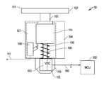
- FIG. 1illustrates one exemplary embodiment of a spring loaded mechanical key switch assembly 10 configured to have variable displacement sensing capability.
- key switch assembly 10includes a depressable key component 101 movably received within a complementary dimensioned cavity 121 defined within key switch chassis housing 104 .
- the depressable key component 101may include a key cap 102 coupled to a shaft 103 , plunger body 114 , and plunger axle 108 .
- the depressable key component 101may be depressable as single unit downward, e.g., as a single piece of plastic that is received within cavity 121 of a plastic key switch housing 104 , although other materials or combinations of materials are possible for both depressable key switch component 101 and key switch housing 104 , e.g., such as ceramic materials. Moreover, it is possible that depressable key component 101 may be made up of two or more assembled pieces.
- key switch housing 104 of this embodimentincludes a displacement-sensing key well 150 having a plunger cavity 153 defined therein into which plunger axle 108 is received when key cap 102 is depressed downward by a force 190 as shown in FIGS. 2 and 4 , e.g., such as may be provided by a user's finger pressing the key cap 102 .
- an internal spring element in the form of a compression coil (or helical) spring 106 made of metal (e.g., such as stainless steel, spring steel, etc.) that is resting on the top of key well 150 (e.g., by virtue of the diameter of coil spring 106 being greater than the internal diameter of plunger cavity 153 and the external diameter of plunger axle 108 )may be provided as shown wrapped around plunger axle 108 and configured to be compressed against the top of key well 150 when key cap 102 is depressed downward within key switch housing chassis 104 .
- compression of internal spring 106provides a resilient force to resist the downward movement of depressable key component 101 , and/or to urge depressable key component 101 upward, within key switch housing chassis 104 such that there is always tension on the user's finger, and to return the depressable key component 101 to its non-depressed extended position.
- a spring loaded mechanical key switch assemblymay be provided with any alternative configuration of one or more spring elements of metal or other suitably elastic material that is suitable for providing a resilient force to resist the downward movement of a depressable key component, imparting tension to a user's finger during downward travel, and/or for urging a depressable key component 101 to return to its extended position, e.g., such as metal torsion springs, metal clock springs, etc.
- spring elementsof metal or other suitably elastic material that is suitable for providing a resilient force to resist the downward movement of a depressable key component, imparting tension to a user's finger during downward travel, and/or for urging a depressable key component 101 to return to its extended position, e.g., such as metal torsion springs, metal clock springs, etc.
- more than one spring elementmay be present.
- FIG. 1Also shown in FIG. 1 is optional digital signal circuitry 109 that is coupled to provide an on/off digital output signal 111 (e.g., to a legacy keyboard controller of an information handling system) when depressable key component 101 is depressed downward by a predetermined extent, e.g., such as when depressable key component 101 has been depressed downward by about 50% of the total possible downward travel length of depressable key component 101 .
- an on/off digital output signal 111e.g., to a legacy keyboard controller of an information handling system
- a predetermined extente.g., such as when depressable key component 101 has been depressed downward by about 50% of the total possible downward travel length of depressable key component 101 .
- a spring loaded mechanical key switch assemblymay only be provided with a displacement-sensing key well 150 that includes variable displacement-sensing circuitry 152 , and not provided with any digital signal circuitry 109 (e.g., mechanical make/break key contacts) such that the spring loaded mechanical key switch assembly is incapable of providing on/off digital output signals 111 .
- displacement-sensing key well 150includes variable displacement-sensing circuitry 152 that is configured to detect and measure downward and/or upward key travel (and/or current position) of depressable key switch component 101 and to provide variable displacement signals 160 of varying character to displacement measurement circuitry 302 as shown.
- the charactere.g., voltage, current, signal state, etc.
- variable displacement signals 160may vary according to the relative displacement of the depressable key component between the extended position and the depressed position of depressable key switch component 101 so as to indicate or to be indicative of the relative displacement of the depressable key component between the extended position and the depressed position.
- Variable displacement-sensing circuitry 152may be implemented using any type, or combination of types, of sensor circuitry (e.g., one or more positional sensors) that is suitable for detecting changes in downward travel distance or depth of depressable key switch component 101 corresponding to downward displacement of a key cap 102 .
- sensor circuitrye.g., one or more positional sensors
- Example types of electrical sensor circuitryinclude, but are not limited to, capacitive sensing circuitry, resistive sensing circuitry, optical sensing circuitry, electrical field (E-field) or magnetic field (H-field) change detection circuitry, etc.
- variable displacement-sensing circuitry 152may be configured to detect and measure downward and/or upward key travel of depressable key switch component 101 and provide variable displacement signals 160 throughout the entire downward and upward travel range of depressable key switch component 101 independent of the operation of digital signal circuitry 109 and conduction of on/off digital output signal 111 .
- variable displacement-sensing circuitry 152may be alternatively configured to detect and measure downward and/or upward key travel of depressable key switch component 101 and provide variable displacement signals 160 only after depressable key component 101 has been depressed downward by a predetermined extent (e.g., about 50% of the total possible downward travel length) to cause digital signal circuitry 109 to provide an on/off digital output signal 111 .
- a predetermined extente.g., about 50% of the total possible downward travel length
- a userwill be able to feel their finger continuing to travel beyond the 50% initial “make” digital signal point, and the variable displacement-sensing circuitry 152 will continue to report various plunger depth levels until 100% downward key travel has been achieved.
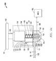
- FIG. 2Ashows one exemplary embodiment of a spring loaded mechanical key switch assembly 100 having one exemplary embodiment of digital signal circuitry 109 in the form of mechanical make/break key contacts 125 and 123 that are coupled to respective separate key switch pins 120 and 122 to provide an on/off digital output signal 111 when depressable key component 101 is depressed to cause contacts 125 and 123 to make contact with each other as shown in FIG. 2 , i.e., by bending contact 123 toward contact 125 .
- plunger body 114also is provided as shown with a positioning ridge 110 that is configured and positioned to displace contact 123 toward contact 125 as depressable key component 101 moves downward within key switch chassis housing 104 .
- Positioning ridge 110may also be provided with a stepped and ramped surface 112 that is configured to mechanically interact or interfere with a bendable contact leg 126 that is biased against ramped surface 112 so as cause a “snap” or “click” action that is detectable by the user when depressable key component 101 is depressed downward by a predetermined extent as shown in FIG. 2A .
- make/break key contacts 125 and 123may be configured such that the “make” (on or closed condition) connection for the switch assembly 100 is made at about the 2 millimeter downward travel position (i.e., greater than or equal to about 50% downward travel) of depressable key component 101 , while the “break” (off or open condition) connection for the switch assembly 100 is maintained above the 2 millimeter downward travel position (i.e., less than about 50% downward travel) of depressable key component 101 .
- downward travel lengthsthat are greater or less than about 4 millimeters may be employed as desired or needed for a given application, and/or that make/break points may be configured to occur at positions of depressable key component 101 that are greater than or less than 50% downward travel.
- a total downward travel length of about 2 millimeters or 1.5 millimetersmay be employed in one embodiment for spring loaded mechanical key switch assemblies that are installed in a notebook computer or other relatively thin form factor information handling system.
- the “make” connection for the switch assemblymay be made at about the 1 millimeter or 0.75 millimeter downward travel position, respectively.
- variable displacement-sensing key well 150includes variable displacement-sensing circuitry 152 that in this exemplary embodiment employs capacitive sensing technology to determine the travel position of the plunger axle 108 .
- variable displacement-sensing circuitry 152 of this embodimentincludes a set of electrical sensors configured as a set of multiple stationary conductive (e.g., metal) elements in the form of aligned conductive sensor rings 154 a to 154 d , and a movable conductive (e.g., metal) element 140 (e.g., plate, ring, strip, etc.) that may be provided as shown disposed on a distal end of plunger axle 108 so that it travels with plunger axle 108 to extend through successive conductive sensor rings 154 a to 154 d in different positions as depressable key component 101 is depressed downward.
- stationary conductivee.g., metal
- a movable conductive element 140e.g., plate, ring, strip, etc.
- conductive sensor rings 154are drawn in perspective view for purpose of illustration relative to plunger axle 108 which extends therethrough. Although illustrated as conductive rings in FIG. 2A , it will be understood that stationary conductive sensor ring 154 may be configured any other suitable geometry (bar-shaped solid, plate-shaped solid, rectangular or square ring shape, diamond ring shape, oval ring shape, etc.) for acting as a stationary capacitive plate to allow measurement of the positioning of movable conductive element 140 relative to each of stationary conductive sensor rings 154 in a manner as described elsewhere herein.
- the movable conductive element 140may be made with a flat or non-flat surface relative to the conductive sensor rings 154 .
- the design and configuration of sensor rings 154 and movable conductive element 140may be made to ensure that the distance between the stationary and movable elements is constant and with a constant dielectric gap width between the stationary and movable elements (in this case, air is the dielectric, although a dielectric is not limited to this and other dielectric materials may be employed).
- movable conductive element 140functions as a movable capacitive plate which may either be coupled to ground or to any constant voltage, e.g., via wire conductor 170 or any other suitable method such as using an electrical conductor within metal plunger axle 108 that itself is electrically coupled to ground or any constant voltage.
- Each of stationary conductive elements 154 a to 154 dmay function as individual stationary second capacitor plates that are each coupled to a respective analog signal trace 160 as an input to displacement measurement circuitry 302 which in this embodiment is provided in the form of a microcontroller (e.g., a Texas Instruments MSP430F55xx family of USB enabled 16-bit ultra-low power microcontrollers (MCU) (such as the MSP430F2111 or MSP430F5508), available from Texas Instruments of Dallas, Tex.) that runs firmware stored on a memory device associated with the microcontroller.
- MCU16-bit ultra-low power microcontrollers
- a voltagemay be applied to the set of stationary conductive sensor rings 154 , and changes in the electric field between each sensor ring 154 and the movable target 140 are measured as values or relative levels of induced voltage measured at each sensor ring 154 .
- the peak voltage of all the sensor rings 154is sensed by the displacement-sensing circuitry 152 and used to determine the travel position of the plunger axle 108 , and thus the downward displacement of depressable key component 101 .
- any other type of digital and/or analog displacement measurement circuitry 302may be employed that is suitable for measuring or otherwise recognizing or reacting to changes in state of variable displacement signals 160 of any variable displacement-sensing mechanical key switch assembly disclosed herein due to downward and upward travel of depressable key switch component 101 along the axis of plunger axle 108 .
- displacement measurement circuitry 302may employ RC capacitive measurement methodology with falling edge event driven interrupt performed on a per pin or signal trace basis. Further information on variable capacitive sensing and/or RC capacitive measurement may be found, for example, in U.S. patent application Ser. No. 12/316,703 filed Dec. 16, 2008; U.S. patent application Ser. No. 12/802,468 filed Jun. 8, 2010; in U.S. patent application Ser. No. 12/930,125 filed Dec. 29, 2010; and in U.S. patent application Ser. No. 13/232,707 filed Sep. 14, 2011, each of which is incorporated herein by reference in its entirety.
- any other type of suitable capacitive-sensing circuitrymay be employed including, for example, any circuitry that uses RC discharge time to measure sensor capacitance as described in U.S. Pat. No. 3,936,674, which is incorporated herein by reference in its entirety.
- displacement measurement circuitry 302may be configured to monitor induced voltage on each of stationary conductive elements 154 in real time via respective signal traces 160 , including at any time during keyboard operation that depressable key component 101 is depressed downward within key switch housing chassis 104 .
- measured induced voltagewill be greatest for any given one of stationary conductive elements 154 a to 154 d when movable conductive element 140 is positioned opposite (at its closest point to) the given stationary conductive element 154 .
- the relative induced voltage of stationary conductive elements 154 a to 154 dmay be compared or otherwise analyzed to determine (e.g., by interpolation of the measured voltage values) a position of movable conductive element 140 when it is located between any given two of stationary conductive elements 154 a to 154 d , as well as when it is positioned above conductive element 154 a or below conductive element 154 d .
- an interpolationmay be made by displacement measurement circuitry 302 to calculate the current position of movable conductive element 140 as being located in-between conductive elements 154 c and 154 d . This indicates that depressable key component 101 is almost entirely pressed downward to its furthest extent.
- spring loaded mechanical key switch assembly 100may be configured such that depressable key component 101 has a total downward travel length of about 4 millimeters within cavity 121 , although greater or lesser travel lengths are alternatively possible.
- four individual stationary conductive elements 154may be spaced center-to-center by about 0.5 millimeters apart, and such that the center of movable conductive element 140 is: directly opposite (or even with) the center of stationary conductive element 154 a when depressable key component 101 has been displaced downward by about 2 millimeters, directly opposite (or even with) the center of stationary conductive element 154 b when depressable key component 101 has been displaced downward by about 2.5 millimeters (as shown in FIG.
- stationary conductive elements 154directly opposite (or even with) the center of stationary conductive element 154 c when depressable key component 101 has been displaced downward by about 3 millimeters, and directly opposite (or even with) the center of stationary conductive element 154 d when depressable key component 101 has been displaced downward by the full 4 millimeters displacement.
- four stationary conductive elements 154are illustrated in FIGS. 2A and 2B , it will be understood that any number of one or more stationary conductive elements 154 may alternatively be employed depending on the displacement measurement resolution that is desired or needed for a given application, including greater than or less than four stationary conductive elements 154 .
- the center-to-center spacing between adjacent stationary conductive elements 154may be selected to define the desired granularity of key travel measurement to be detected for depressable key component 101 .
- FIGS. 2A and 2Bis exemplary only, and that other mechanical and electrical contact configurations of spring loaded mechanical key switch assembly 100 and/or sensor configurations of displacement-sensing circuitry 152 may be employed in other embodiments.
- displacement-sensing circuitry 152may be any other suitable type, or combination of types, of sensor circuitry that is suitable for detecting changes in downward travel distance of plunger axle 108 corresponding to press depth of a key cap 102 .
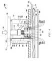
- FIG. 3illustrates another exemplary embodiment of a spring loaded mechanical key switch assembly 300 that is also configured to have variable displacement sensing capability using optical sensing circuitry.
- key switch assembly 300also includes a depressable key component 101 that is movably received within a complementary dimensioned cavity 121 defined within key switch chassis housing 104 .
- the depressable key component 101may include a key cap 102 coupled to a shaft 103 , plunger body 114 , and plunger axle 108 as shown.
- key switch housing 104 of the FIG. 3 embodimentincludes a displacement-sensing key well 150 having a plunger cavity 153 defined therein into which plunger axle 108 is received when key cap 102 is depressed downward by a force 190 as shown in FIG. 4 .
- An internal coil spring 106(e.g., resting on the top of key well 150 ) may also be provided as before around plunger axle 108 and configured to be compressed when key cap 102 is depressed downward within key switch housing chassis 104 .
- mechanical make/break key contacts 323 and 325 of one exemplary embodiment of digital signal circuitry 109are coupled to respective separate key switch conductors 120 and 122 to provide an on/off digital output signal 111 when depressable key component 101 is depressed to cause contacts 325 and 323 to make contact with each other as shown in FIG. 4 , i.e., in this embodiment by bending contact 323 toward contact 325 .
- the 323 to 325 electrical make connectionis continued thru the duration of the 2 mm-4 mm key travel (or other travel distance with which the key switch assembly has been configured).
- plunger body 114is provided with an extending finger 301 that is positioned and configured to displace contact 325 toward contact 323 as depressable key component 101 moves downward within key switch chassis housing 104 .
- no optional stepped and ramped surfaceis provided, so that no “snap” or “click” action is detectable by the user when depressable key component 101 is depressed downward in the manner as of the embodiment of FIGS. 2A and 2B .
- variable displacement sensing capabilitymay be provided for a variety of configurations of spring loaded mechanical key switches, including different types of make/break contacts and/or different configurations of depressable key components and key switch housing chassis 104 .
- a displacement-sensing key well 150that includes displacement-sensing circuitry 152 that in this exemplary embodiment includes multiple single channel optical sensor pairs configured as four multiple light sources (e.g., light emitting diodes “LEDs” or other suitable light emitting elements) 350 a to 350 d stacked on top of each other on one side of plunger cavity 153 and that are each mechanically and optically aligned with a corresponding one of four respective optical sensors (e.g., phototransistors) 352 a to 352 d on the other side of the plunger cavity 153 .
- LEDslight emitting diodes
- respective optical sensorse.g., phototransistors
- Optical sensors 352may be, for example, photo microsensors, or other suitable optical sensor elements) that are stacked on top of each other on an opposing side of plunger cavity 153 as shown with each light source/optical sensor pair being positioned at a different key travel depth, it being understood that more than four or less than four optical sensor pairs may be alternatively employed depending on the displacement travel measurement resolution that is desired or needed for a given application. Moreover, a fewer number of light sources 350 may be provided than optical sensors 352 , e.g., one light source 350 configured to illuminate four optical sensors 352 .
- a suitable LED/phototransistor combination 350 / 352 known as a Dual Channel Transmissive optical sensoris available as part number TCUT1300X01 from Vishay, and provides one LED paired to two phototransistors.
- a multi-channel optical sensormay be employed in one embodiment to achieve space savings over use of multiple single channel sensors.
- suitable optical sensorsinclude phototransistor devices available from Omron Electronic Components, LLC.
- a displacement-sensing key well 150may be employed that includes displacement-sensing circuitry 152 that includes multiple transmissive type photointerrupters such as ROHM part number RPI-121 available from Rohm Co. Ltd. which are stacked on top of each other (4 total shown).
- the transmissive type photointerrupterhas a LED light source 350 on one side of plunger cavity 153 and is mechanically and optically aligned with a corresponding one of four respective optical sensors (e.g., phototransistors) on the other side of the plunger cavity 153 .
- Use of the transmissive type photointerruptermay be selected due to its ability to be minimally influenced from stray light.
- a displacement-sensing key well 150may be employed that includes displacement-sensing circuitry 152 that includes multiple reflective type photo sensors such as ROHM part number RPR-220 available from Rohm Co. Ltd.
- depressable key component 101may be configured in one exemplary embodiment to have a total downward travel length capability of about 4 millimeters within cavity 121 , and optical sensor pairs may be spaced center-to-center by about 0.5 millimeters apart, although other values of key component travel length and/or center-to-center spacing may be employed in other embodiments.
- the center-to-center spacing between adjacent stacked optical sensor pairsmay be selected to define the desired granularity of key travel to be detected for a given depressable key component 101 .
- the number of displacement levels detected and reported by signals 160corresponds to the number of optical sensor pairs provided within displacement measurement circuitry 302 .
- each light source 350is configured to emit a light beam across plunger cavity 153 to a corresponding one of light sensors 352 .
- plunger cavity 153is open to allow a light beam from each of light sources 350 to be received by its corresponding optical sensor 352 , indicating that depressable key component 101 is not depressed.
- FIG. 3when depressable key component 101 is in its non-depressed (fully-extended) state, plunger cavity 153 is open to allow a light beam from each of light sources 350 to be received by its corresponding optical sensor 352 , indicating that depressable key component 101 is not depressed.
- plunger axle 108enters plunger cavity 153 between the successive pairs of aligned light sources 350 and optical sensors 352 in different positions as depressable key component 101 is depressed downward as shown.
- displacement measurement circuitry 302may be configured to monitor in real time analog signal traces 160 corresponding to each of the individual respective optical sensors 352 a to 352 d to detect when a light beam from a corresponding respective paired light source 350 is being received across cavity 153 , and when it has been obscured by presence of plunger axle 108 within cavity 153 . In this way, displacement measurement circuitry 302 may continually determine and re-determine how far plunger axle 108 and depressable key component 101 has been depressed or displaced downward at any given time based on the which optical sensors 352 are still receiving light from light source's 350 . For example, in FIG.
- spring loaded mechanical key switch assembly 300is shown mounted (e.g., by “pop-in” mechanical interference fit) within an optional opening or hole 394 defined in a component side of a printed circuit board (PCB) 380 that includes circuitry, such as separate key switch conductors 120 and 122 that are configured for coupling to provide an on/off digital output signal 111 (e.g., to circuitry such as a legacy keyboard controller 910 of FIG. 9 ), it being understood that a key switch assembly may be mounted to a PCB 380 or other suitable support structure in any suitable manner, e.g., including surface mounted to PCB 380 . It will also be understood that the spring loaded mechanical switch assembly 100 of FIGS.
- 2A-2Bmay be similarly mounted to a PCB, e.g., for a computer keyboard assembly application.
- Any suitable type of displacement measurement circuitrymay be coupled to receive a signal output 160 of each of phototransistors 352 via leads 326 extending from key switch chassis housing 104 , e.g., via signal traces that may be provided on PCB 380 as shown and soldered to leads 326 to provide signals from LED/phototransistor pairs (e.g., such as to displacement measurement circuitry 302 of FIGS. 1-2 and 9 ).
- Power for light sources (LEDs) 350may be provided by voltage signals found on the PCB 380 (e.g., a voltage trace on PCB 380 , such as a filtered or switched version of a USB Vcc signal).
- some of the sensorsare found internal to the key switch housing (on the component side of the PCB), and some are found in the key switch housing but requiring a hole in the PCB to accommodate deeper key travel distance.
- FIGS. 3-4may be implemented using displacement measurement circuitry 302 that is similar as the embodiment of FIGS. 1-2 .
- displacement measurement circuitry 302may be provided in the form of a controller, e.g., a 16-bit ultra-low power capacitive sensing microcontroller part number MSP430F2111 available from Texas Instruments of Dallas Tex.
- MSP430F2111available from Texas Instruments of Dallas Tex.
- displacement measurement circuitry 302may be configured to measure the voltage from each phototransistor output 160 , and determine the amount of key displacement.
- FIGS. 3-4also illustrate how optional key cap lighting may be provided for spring loaded mechanical key switch assembly 300 , it being understood that similar key lighting components may be provided for other embodiments and different configurations of spring loaded mechanical key switch assemblies, such as those illustrated in FIGS. 1-2 and FIG. 5 .
- key cap 102may have one or more light-transmissive key feature/s 302 (e.g., such as a laser etched alphanumeric character, laser etched key cap rim, defined aperture, transparent or translucent key surface, and/or other light transmissive feature) that extends through the keycap 102 from beneath the key cap 102 through the top surface of the key cap 102 such that light 398 emitted from beneath the key cap 102 by a light pipe 390 is visible by a user from above the key cap 102 through the light transmissive key feature/s 302 .
- a top view of such light-transmissive key features 302is illustrated in the embodiment of FIG. 7 . Further information on laser etched indicia and key rims may be found in U.S. Pat. No. 8,411,029, which is incorporated herein by reference in its entirety.
- light pipe 390passes through an opening 391 defined in the key switch chassis housing 104 to one side of the mechanical switch components (shaft 103 , plunger body 114 , plunger axle 108 , spring 106 and key well 150 ) from a planar light spreader component 382 (e.g., acrylic sheet, polycarbonate sheet such as Lexan®, or other suitable light-transmitting material) through an opening 392 defined in PCB 380 to a position beneath the key cap 102 .
- Light pipe 390may be any suitable light conductive structure that is configured to pipe light from light spreader 382 through PCB 380 and switch chassis housing 104 to the underside of key cap 102 .
- light spreader 382may be a substantially light-transparent material that may be optionally laser-etched to control diffusion of light received from light sources 510 , e.g., so as to control light spreading in order to contain emitted light from selected light sources 510 within specified regions of light spreader 382 such as further described in relation to FIG. 8 .
- an optional light reflective film 384may be provided beneath light spreader component 382 as shown for purposes of reflecting and spreading light from light sources 510 more evenly across light spreader 382 .
- the space shown between PCB 380 and light spreader 382 , and the space shown between light spreader 382 and reflective film 384may be configured as suitable to allow for operative cooperation between these components, and in one exemplary embodiment these may be planar components that are closely butted up against each other with substantially no space between the components with the exception that tolerance of spacing between PCB 380 and light spreader 382 may be configured to accommodate the depth of key well 150 .
- any needed or desired spacing between PCB 380 and light spreader 382may be provided by a separate spacer layer/s provided between PCB 380 and light spreader 382 , and length (and therefore depth) of light pipe 390 may be adjusted accordingly to maintain suitable operative relationship with light spreader 382 .
- Light pipe 390 of FIGS. 3-4may be constructed of any suitable light transmissive material (e.g., such as acrylic, polycarbonate, etc.) and may be configured as an elongated cylindrical shape as shown, although other shapes are possible such as elongated square shape, elongated oval shape, elongated rectangular shape, etc.
- Light pipe 390may be of any dimension (length, cross-sectional area, etc.) that is suitable for transmitting sufficient light from light spreader 382 that is positioned below the key assembly 300 to illuminate a desired portion or portions of key cap 102 in un-pressed or fully depressed position of the key cap 102 .
- the upper light-emitting end of light pipe 390 underneath key cap 102may be flush with a top surface of key switch chassis housing 104 , or may alternatively be recessed below key switch chassis housing 104 or extend above key switch chassis housing 104 .
- the upper light-emitting end of light pipe 390 underneath key cap 102may also be optionally textured, angled, or otherwise configured in a manner that diffuses emitted light 398 or directs the emitted light 398 in one or more desired directions, e.g., such as directed toward the center of the key cap 102 and away from the outer edge of the key cap 102 .
- more than one light pipe 390may be provided to illuminate a key cap 102 of a given single spring loaded mechanical key switch assembly 300 .
- a lower first end of light pipe 390may be positioned to butt up against or otherwise contact or lie adjacent to light spreader component 382 in a manner that allows light to be transferred from light spreader 382 to light pipe 390 .
- a relatively small diffuser areae.g., a laser etched “dot”
- Light spreader 382may in turn be edge-lit from right-angle oriented LEDs (e.g., RGB LEDs or single color LEDs) 510 as shown, it being understood that light sources 510 may be alternatively oriented relative to spreader 382 at angles other than 90 degrees and/or in any other position relative to edges or sides of light spreader 382 that is suitable for emitting light that is transferred into light spreader 382 .
- the light transferred from light spreader 382 to light pipe 390is then transmitted through light pipe 390 so as to shine upwards to the underside of key cap 102 in a manner such that the light illuminates the light transmissive key feature 302 in a manner that is visible by a user.
- light pipe 390may be assembled to other components in any suitable manner.
- light pipe 390may be pre-assembled as an integral part of a spring loaded mechanical key switch assembly 300 that is then assembled to PCB 380 through aperture 392 at the same time the remainder of spring loaded mechanical key switch assembly 300 (e.g., key well 150 and electrical pins 323 , 325 and 326 ) are assembled to PCB 380 .
- light pipe 390may be provided as an integral part of light spreader 382 (e.g., glued to or inserted with a friction fit into an complementary-dimensioned opening defined in the upper surface of spreader 382 ) to which the spring loaded mechanical key switch assembly 300 and PCB 380 are then assembled by sliding aperture 392 of the key switch housing chassis 104 over light pipe 390 when assembling key assembly 300 to PCB 380 .
- FIG. 5illustrates another exemplary embodiment of a lighted spring loaded mechanical key switch assembly 500 having a key cap 102 with light transmissive key feature 302 but that does not have having variable displacement sensing capability.
- spring loaded mechanical key switch assembly 500is provided with plunger cavity 553 defined within a key well 550 that includes no displacement sensing circuitry but that otherwise has digital make/break mechanical key contact circuitry similar to the embodiment of FIGS. 2A-2B .
- spring loaded mechanical key switch assembly 500includes a light pipe 390 that is similarly configured to illuminate light transmissive key features 302 from light provided by light spreader 382 in the manner of the embodiment of FIGS. 3 and 4 .
- lighted spring loaded mechanical key switch assembly 500may also be provided with any suitable digital signal circuitry 109 such as described elsewhere herein.
- a lighted spring loaded mechanical key switch assembly having a plunger cavity 153 defined within a displacement-sensing key well 150 that includes variable displacement-sensing circuitry 152 , but that has no digital make/break mechanical key contact circuitry or other type of digital signal circuitry 109may be provided with a light conductive structure such as a light pipe 390 , e.g., to illuminate light transmissive key features 302 of a keycap 102 of a key switch assembly that is incapable of providing on/off digital output signals 111 .
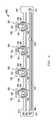
- FIG. 6illustrates a side view of a keyboard assembly 600 that includes multiple spring loaded mechanical key switch assemblies 300 that are assembled to PCB 380 , light spreader 382 , and reflective film 384 in a manner as previously described.
- multiple edge mounted right angle light sources 510are arrayed around at least two edges of light spreader 382 to provide light for illuminating spreader 382 , light pipes 390 and key caps 102 of keyboard assembly 600 .
- an optional face plate 610e.g., planar sheet of metal and/or plastic
- Each of face plate 610 , PCB 380 , light spreader 382 , and reflective film 384may be operatively supported in relation to each other from edge mounting points (e.g., brackets, grooves, shelves, etc.) provided on the interior sides or other surfaces of a chassis 691 that surrounds or otherwise houses the components of keyboard assembly 600 .
- edge mounting pointse.g., brackets, grooves, shelves, etc.
- FIG. 7illustrates an exploded perspective view of a keyboard assembly 700 , showing positioning of four spring loaded mechanical key switch assemblies 300 with plastic mounting guides 395 that are each positioned for assembly into key assembly openings 394 defined in PCB 380 . Also shown are light pipes 390 corresponding to each key switch assembly 300 that are positioned for insertion into four corresponding light pipe openings 392 defined in PCB 380 .
- Light spreader 382is shown positioned between PCB 380 and a combination flex circuit assembly 620 that includes reflective film 384 integrated together with right angle mounted light sources 510 onto a flex circuit component (e.g., polyimide, polyether (ether) ketone, transparent conductive polyester, etc.).
- a flex circuit componente.g., polyimide, polyether (ether) ketone, transparent conductive polyester, etc.
- light sources 510may be adhered or otherwise mounted to the flex circuit sheet before assembly to light spreader 382 and PCB 380 as part of a keyboard assembly that is contained within or otherwise mounted as part of a keyboard chassis, e.g., with an optional face plate 610 overlying PCB 380 as shown in FIG. 6 .
- a flex circuitmay be adhered to the underside of a thin white reflective plastic-like film 384 , and the flex circuit may be configured to route, for example, the LED power and return signals, current limiting resistors, and right angle surface mount RGB LEDs.
- a cutoutmay be provided in the reflective film 384 to allow each right angle LED to pop up thru the top side of the reflective film 384 so that the LED can light up the cross-sectional area (or side) of the light spreader 382 .
- FIG. 7Also shown in FIG. 7 are four additional pairs of key assembly openings 394 and light pipe openings 392 defined in PCB 380 for receiving additional spring loaded mechanical key switch assemblies 300 and light pipes 390 .
- a keyboard assemblymay be configured with any pattern and number of pairs of key assembly openings 394 and light pipe openings 392 as needed or desired to fit a given back-lighted keyboard application.
- 104 pairs of key assembly openings 394 and light pipe openings 392may be defined in PCB 380 in a pattern suitable for mounting and backlighting 104 spring loaded mechanical key switch assemblies 300 of a QWERTY keyboard, although other patterns and numbers of pairs of key assembly openings 394 and light pipe openings 392 may be provided in other embodiments to support other types and sizes of keyboard assemblies.
- FIG. 8illustrates a top view of one exemplary embodiment of a single sheet light spreader component 382 assembled to right angle mounted light sources 510 in an operative relationship to provide multiple separate backlighting zones (zones 1, 2, 3 and 4 labeled as 802 , 804 , 806 and 808 ) for a keyboard assembly.
- eight light sources 510may be mounted onto a combination flex circuit assembly 620 that underlies light spreader 382 and is not visible in FIG. 8 .
- such a light spreader configurationmay be provided for a full size computer keyboard assembly, such as a 104-key QWERTY keyboard assembly.
- each backlighting zonemay be dimensioned and configured to underlie and separately light a portion of the total number of keys.
- FIG. 8illustrates a single sheet light spreader component 382 , it will be understood that a light spreader component 382 having multiple sheets or multiple light-transmissive segments is also possible. Further, it will be understood that in other embodiments not all key switch assemblies need be back-lighted, nor do all segments of a keyboard assembly need to underlain by a light-transmissive light spreader component.
- FIG. 8illustrates a configuration capable of backlighting 15 mechanical key switch assemblies 300 in each of zones 1, 2 and 3; and 21 mechanical key switch assemblies in zone 4 , using two light sources in each zone. This translates into a ratio of backlit keys to light sources that is equal to 66 keys/8 light sources or 8.25 backlit keys per light source.
- key caps 102 of multiple spring loaded mechanical key switchesmay be backlit by one or more common light sources 510 to achieve a ratio of backlit keys to light sources that is greater than 1. This is as opposed to conventional spring loaded mechanical key switches that each employ a separate LED for key lighting, i.e., using a ratio of backlit keys to light sources that is equal to 1.
- the disclosed systems and methodsthus may be implemented in one embodiment using fewer light sources powered only by USB bus power (without an AC adapter) to backlight substantially all the keys of a large keyboard assembly (e.g., including keyboard assemblies having 80 or more keys such as a 104-key QWERTY keyboard) than would be required by a conventional spring loaded mechanical key switch keyboard assembly of similar size and having one light source per key (which would require use of an AC adapter).
- a typical RGB LED light sourcedraws 60 milliamps (20 mA for red, 20 mA for green, and 20 mA blue).
- a conventional mechanical key switch keyboard assembly with 104 keys that each has its own RGB LED key lightwould draw a total 31 watts to power the 104 LEDs alone, and would therefore require an AC/DC adapter to power the lighted keyboard assembly.
- a 104-key mechanical key switch keyboard assembly employing 12 edge mounted RGB LEDs as light sources 510 to illuminate a light spreader 382 and light pipes 390 provided for each key in a manner as disclosed hereinwould only draw a total of 3.5 watts, and could therefore be powered by two USB 2.0 ports from an attached information handling system, which have a maximum capacity of 5 watts. This avoids the need for powering the disclosed keyboard assembly from an AC/DC adapter.
- light sources 510 1may be separately controlled to provide different lighting characteristics (e.g., different light intensity, different light color, different light flashing pattern, etc.) and/or lighting animation/graphics at any given time to the light pipes and key caps overlying zone 1 than light sources 510 2 , 510 3 and 510 4 display to the light pipes and key caps overlying zones 2, 3, and/or 4.
- Each of zoned light sources 510 2 , 510 3 and 510 4may also be separately controlled relative to light sources 510 1 and to each other.
- light sources 510 of the different zones 802 , 804 , 806 and 808may be individually controlled to display a light pattern that moves across the keyboard area (e.g., such as a sequential change of color or flashing pattern in the form of a “wave” moving from one zone to another across the keyboard), to display different colors simultaneously in different zones, to display a pattern of flashing light in one zone while all other zones are non-flashing, etc.
- a light sources 510 of the different zones 802 , 804 , 806 and 808may be individually controlled to display a light pattern that moves across the keyboard area (e.g., such as a sequential change of color or flashing pattern in the form of a “wave” moving from one zone to another across the keyboard), to display different colors simultaneously in different zones, to display a pattern of flashing light in one zone while all other zones are non-flashing, etc.
- FIG. 9illustrates a block diagram for a keyboard system 900 including both variable displacement-sensing spring loaded mechanical key switch assemblies 904 and digital output-only spring loaded mechanical key switch assemblies 906 (e.g., that do not have displacement-sensing circuitry 152 ).
- Examples of conventional spring loaded mechanical key switch assemblies 906include, but are not limited to, Cherry MX Key Switches available from ZF Electronic Systems of Pleasant Prairie, Wis.; and Kailh Switches available from Kaihua Electronics Co., Ltd from Tangxia Town, Dongguan City, Guangdong province, China.
- Each of variable displacement-sensing mechanical key switch assemblies 904may be, for example, a spring loaded mechanical key switch assembly 10 , 100 , or 300 such as described herein in relation to FIGS. 1, 2A-2B, 3 and 4 .
- Each of mechanical key switch assemblies 906may be, for example, a conventional spring loaded mechanical key switch assembly or a key switch assembly that is similar to one of spring loaded mechanical key switch assemblies 10 , 100 , or 300 but without the displacement-sensing circuitry 152 and variable displacement output signals 160 .
- Key switch assemblies 904 and 906may together be provided in any suitable number or configuration, e.g., so as together implement a total of 104 mechanical key switch assemblies to implement a QWERTY keyboard configuration, with just a portion of the total keys (e.g., corresponding to W, A, S and D keys) being variable displacement-sensing spring loaded mechanical key switch assemblies 904 . It will be understood, however, that all key switch assemblies of a keyboard may alternatively be configured as variable displacement-sensing spring loaded mechanical key switch assemblies 904 .
- backlighting circuitry componentsthat include one or more backlight controller/s 920 , e.g., such as an ST Micro 8051F347 microcontroller available from ST Microelectronics of Geneva, Switzerland.
- event driven backlightingmay be implemented by communicating events from an application programming interface (API) executing on a host information handling system across communication interface 907 to the backlight controller 920 , which responds by communicating lighting commands (e.g., via I 2 C bus) to light source current driver circuitry component/s 931 which each drive one or more light sources (e.g. LEDs) 510 accordingly to control on, off and/or color operation of the light sources.
- APIapplication programming interface
- each of light source current driver circuitry component/s 510may be a MAX7313 serial interfaced peripheral available from Maxim Integrated of San Jose, Calif., each of which is capable of driving up to five RGB LEDs 510 of a given backlighting zone 802 , 804 , 806 or 808 of light spreader 382 of FIG. 8 , e.g., to light individual spring-loaded mechanical key switch assemblies 300 or 500 equipped with light pipes 310 previously described.
- a keyboard controller 910is coupled to receive an on/off digital output signal 111 (e.g., via a legacy key matrix) from digital signal circuitry 109 of each key switch assembly 904 and 906 that is detected by controller 910 as representing a digital key switch assembly that is either pressed or not pressed.
- Keyboard controller 910may be implemented, for example, as a microcontroller (e.g., legacy 8051-based microcontroller or custom microcontroller) that runs firmware stored on a memory device associated with the keyboard controller 910 .
- Control circuitry within the keyboard controller 910processes these digital key signals 111 and is connected to an output communication path so that this processed digital key information 950 can be communicated to external devices that are external to the keyboard system 900 , such as host components of an information handling system (e.g., such as desktop computer or notebook computer) that includes a host processor such as a CPU, e.g., through a universal serial bus (USB) interface 907 or other suitable interface.
- host components of an information handling systeme.g., such as desktop computer or notebook computer
- a host processorsuch as a CPU
- USBuniversal serial bus
- all components of keyboard system 900may contained within a chassis 691 of a keyboard assembly 600 such as illustrated in FIG. 6 , although this is optional.
- external devicessuch as host processing devices, may be coupled to receive signals from the components of keyboard system 900 that are contained within a chassis 691 .
- external devicescan optionally communicate control and/or other configuration information to the keyboard controller through this same output communication interface 950 .
- Further information on legacy keyboard controller operationmay be found in U.S. patent application Ser. No. 12/802,468 filed Jun. 8, 2010; in U.S. patent application Ser. No. 12/930,125 filed Dec. 29, 2010; and in U.S. patent application Ser. No. 13/232,707 filed Sep. 14, 2011, each of which is incorporated herein by reference in its entirety.
- Examples of possible information handling system componentsmay be found described in U.S. patent application Ser. No. 12/586,676, filed Sep. 25, 2009, now U.S. Pat. No. 8,307,222; and in U.S. patent application Ser. No. 13/232,707 filed Sep. 14, 2011, each of which is incorporated herein by reference in its entirety.
- displacement-sensing circuitry 152 of each key switch assembly 904provides variable displacement signals 160 to displacement measurement circuitry 302 as shown.
- multiple phototransistor outputs 160may be routed to GPIO input lines of a microcontroller configured to operate as displacement measurement circuitry 302 .
- Variable displacement signals 160may be analog signals indicating the amount of downward displacement that has been applied to depressable key components 101 of one or more key switch assemblies 904 , as previously described.
- variable displacement analysis block 990 displacement measurement circuitry 302When a given spring loaded mechanical switch assembly 904 is depressed, one or more corresponding analog signal/s 160 indicating or indicative of the amount of downward displacement that has been applied to depressable key components 101 of the given key switch assembly 904 may be provided to variable displacement analysis block 990 displacement measurement circuitry 302 as shown. It will be understood that in one embodiment the variable displacement signals 160 may alternatively be multiplexed with each other to reduce the number of separate signal paths 160 required, e.g., using a crossbar switch or other suitable signal multiplexing technology.
- variable displacement keys 904may be pressed simultaneously, and multiple corresponding analog signal outputs 160 received from each key 904 may be processed by the displacement measurement circuitry 302 for each of the multiple displacement outputs 951 reported (one per respective key 904 ).
- spring loaded mechanical key switch assembly 300such as illustrated in FIGS. 3-4 , assuming for sake of illustration only that the spring loaded mechanical key switch assembly 300 is configured to support a total of 4 millimeter of downward travel for depressable key component 101 from fully extended position and has four optical sensor pairs 350 / 352 .
- the operation of spring loaded mechanical key switch assembly 300proceeds as follows in response to a downward pressure 190 applied by the finger of a user.
- the electrical “make” connectionis made by virtue of contact between make and break key contacts 325 and 323 and is reported to the keyboard controller 910 (e.g., a conventional legacy Keyboard MCU).
- the first (uppermost) optical sensor pair 350 a / 352 adetects that depressable key component 101 has traveled downward to its depth and sends a corresponding signal 160 a to the displacement measurement circuitry 302 to indicate this has key displacement event occurred. As shown in FIGS.
- other sensor pairs 350 / 352are stacked on top of one another, e.g., to detect each additional 0.5 mm travel of key press depth from one another.
- the second optical sensor pair 350 b / 352 bdetects this occurrence and sends a corresponding signal 160 b to the displacement measurement circuitry 302 to indicate this key displacement event has occurred.
- the third optical sensor pair 350 c / 352 cdetects this occurrence and sends a corresponding signal 160 c to the displacement measurement circuitry 302 to indicate this key displacement event has occurred.
- the fourth optical sensor pair 350 d / 352 ddetects this occurrence and sends a corresponding signal 160 d to the displacement measurement circuitry 302 to indicate this key displacement event has occurred.
- Displacement measurement circuitry 302may be provided in one exemplary embodiment as an integrated part of a keyboard device body, e.g., contained within a chassis of the keyboard together with other components of a keyboard assembly such as illustrated in FIGS. 6 and 7 .
- one or more components and/or processing tasks of displacement measurement circuitry 302may alternatively be integrated or otherwise implemented within a microcontroller that is operating as the keyboard controller 910 and/or as part of the host information handling system to which the keyboard is connected, if desired.
- One or more of the components of displacement measurement circuitry 302could also be implemented with external circuitry, as well.
- displacement measurement circuitry 302may be implemented by any alternative configuration of one or more processing devices (e.g., controller, microcontroller, processor, microprocessor, ASIC, FPGA, CPU, etc.) of an information handling system or a peripheral component thereof, and alone or together with other types of information handling system processing tasks.
- processing devicese.g., controller, microcontroller, processor, microprocessor, ASIC, FPGA, CPU, etc.
- displacement measurement circuitry 302includes a variable displacement analysis block 990 (that receives variable displacement signals 160 ) and memory that include variable displacement profile data 995 (e.g., as user configurable control parameters per level or extent of sensed key displacement on a per game or per application basis).
- variable displacement profile datamay be loaded and/or modified in memory 995 from an external device across communication path 951 , e.g., from an attached host using an application programming interface (API).
- APIapplication programming interface
- the variable displacement profile datamay be loaded from memory 995 into the Variable Displacement Analysis block (VDA) 990 .
- VDAVariable Displacement Analysis block
- the profile data 995may be used by VDA block 990 as parameters for making decisions in the VDA block 990 , e.g., such as understanding how much key switch displacement is required before triggering a particular scan code, and/or for specifying behavior resulting from any particular pressed variable displacement-sensing spring loaded mechanical key switch assembly 904 .
- the scan codeis output from the VDA 990 via the communication path 951 to the communication interface 907 to an external device (e.g., such as to a Host PC system via a USB bus interface).
- a usermay assign a multi-character sequence (or macro) to the variable displacement profile data 995 for at least one given variable displacement-sensing key switch assembly 904 that corresponds to one or more particular sensed displacement levels for the given key assembly 904 .
- a unique scan code 901 corresponding to the sensed displacement levelmay be output from displacement measurement circuitry 302 and sent via path 951 to an appropriate device driver (e.g., USB Human Interface Device “HID” driver) executing on a CPU of a host system.
- an appropriate device drivere.g., USB Human Interface Device “HID” driver
- the USB HID device drivermay then generate and send a HID keyboard report in the form of a variable displacement keyboard event to a variable displacement macro selector component of a middleware layer executing on the CPU of the host system.
- the variable displacement macro selector componentintercepts this keyboard event information and may in turn provide a modified variable displacement scan code to a user application layer that provides the multi-character sequence desired for the sensed displacement level of the given key switch assembly 904 .
- keyboard profile data 995may be customized on a per game basis, and the appropriate profile data 995 loaded into the VDA 990 once the corresponding game is loaded and running on the connected host information handling system.
- this capabilitymay be supported by assigning individual macros to an unassigned scan code 901 that is one of multiple scan codes 901 supported by each variable displacement-sensing key switch assembly 904 of a keyboard assembly or other input/output device.
- scan codesmay be dynamically selected in real time depending on the amount of pressure translating into measured key displacement that is applied to a given key switch 904 based on the user defined profile data 995 for that given key switch 904 , in a manner as described for variable pressure sensing in U.S. patent application Ser. No. 12/930,125 filed Dec. 29, 2010; and in U.S. patent application Ser. No. 13/232,707 filed Sep. 14, 2011, each of which is incorporated herein by reference in its entirety.
- variable displacement-based scan codes 901may be generated and processed in the same manner as described for VPS scan codes in U.S. patent application Ser. No. 13/232,707, in which case the same type of USB HID driver may receive the variable displacement-based scan codes as receives the VPS pressure-based scan codes in U.S. patent application Ser. No. 13/232,707.
- the variable displacement keyboard eventsmay be generated by the USB HID driver in the same manner as VPS keyboard events are generated in U.S. patent application Ser. No. 13/232,707, and the USB HID driver may provide these variable displacement keyboard events to a variable displacement macro selector of a middleware layer that operates in the same manner as VPS macro selector component of U.S. patent application Ser. No.
- variable displacement-based scan codese.g., macro information in the form of a multi-key sequence
- VPS macro selector component of U.S. patent application Ser. No. 13/232,707performs these tasks based on identity of a pressed key and the key's pressure level sensed.
- a single spring loaded mechanical switch key assemblymay be employed to support performing, for example, 5 macros (acting as 5 virtual keys), to support switching between macro outputs in real-time based on a variable input such as sensed key displacement, and/or to support different (e.g., user programmable and/or selectable) correlations of key output behaviors to sensed key displacement.
- a variable inputsuch as sensed key displacement
- different correlations of key output behaviors to sensed key displacemente.g., user programmable and/or selectable correlations of key output behaviors to sensed key displacement.
- use of scan codes and other variable pressure sensing features described in U.S. patent application Ser. No. 12/930,125 filed Dec. 29, 2010 and in U.S. patent application Ser. No. 13/232,707 with regard to pressure-sensing digital output circuitry and variable-pressure keysmay be similarly implemented using displacement measurement circuitry 302 , e.g., using sensed key displacement as a proxy for sensed key pressure.
- displacement measurement circuitry 302may be implemented using any one or more circuitry components suitable for receiving analog signals 160 representative of key displacement from variable displacement-sensing circuitry 152 of key switch assemblies 904 , and for selecting and providing in real time scan code/s corresponding to the key displacement applied to each of key switch assemblies 904 .
- external devicesmay optionally communicate control and/or other configuration information to the displacement measurement circuitry 302 and/or keyboard controller 910 through communication interface 907 .
- communication interface 907is illustrated in FIG. 9 , it will be understood that communication paths 950 and/or 951 may alternatively communicate with other devices in other wired or wireless ways, for example, via a Bluetooth interface if a wireless interface is desired.
- mode signal 961may be provided from variable displacement analysis block 990 of displacement measurement circuitry 302 to keyboard controller 910 to indicate to keyboard controller 910 whether or not to output processed digital key information on output communication path 950 corresponding to on/off digital output signals 111 from variable displacement-sensing key switch assemblies 904 .
- key assemblies 904may be designated for sole operation as variable displacement keys (e.g., such as W, A, S and D keys).
- keyboard controlleronly outputs displacement-based scan codes 901 based on signals 160 from key switch assemblies 904 , but does not output digital key information 950 corresponding to on/off digital output signals 111 received from key switch assemblies 904 .
- the attached host information handling systemsmay enter a standby or a security state (e.g., due to a specified elapsed time of inactivity) that requires entry of a password using digital on/off key signals 111 entered from one or more of the designated “variable displacement only” key switch assemblies 904 .
- a usermay desire to use one or more of the designated “variable displacement only” key switch assemblies 904 as momentary on digital keys to provide digital on/off key signals 111 , e.g., for data or password entry.
- displacement measurement circuitry 302may be controlled (e.g., by a control signal received from a host processor on occurrence of host standby condition, and/or by user keyboard entry code) to provide mode signal 961 to cause keyboard controller 910 to output processed digital key information 950 corresponding to on/off digital output signals 111 received from key switch assemblies 904 for as long as necessary or desired, e.g., for a particular operation purpose.
- mode signal 961may be used to toggle key operation for variable displacement-sensing key switch assemblies 904 between “variable displacement-only” analog output operation and digital output operation.
- displacement measurement circuitry 302may alternatively or additionally be implemented to process analog variable displacement signals 160 received from variable displacement-sensing key switch assemblies 904 in the same manner that pressure-sensing digital output circuitry processes analog output signals from variable pressure sensing analog keys as described in U.S. patent application Ser. No. 13/232,707 filed Sep. 14, 2011, which is incorporated herein by reference in its entirety.
- keyboard controller 910may alternatively or additionally be implemented to process on/off digital output signals 111 from digital signal circuitry 109 of each key switch assembly 904 and 906 in the same manner that legacy keyboard controller 110 processes digital output signals received via a key matrix from digital keys as described in U.S. patent application Ser. No. 13/232,707 filed Sep.
- variable displacement-sensing capabilitymay be advantageously utilized to implement variable pressure features, and operation of displacement measurement circuitry 302 may interact with operation of keyboard controller 910 in the same way that pressure-sensing digital output circuitry interacts with the legacy keyboard controller of U.S. patent application Ser. No. 13/232,707.
- legacy keyboard support and/or haptics capabilitymay be provided to a keyboard assembly that employs variable displacement sensing spring loaded mechanical key switch assemblies 904 by utilizing features similar to those described in U.S. patent application Ser. No. 12/930,125 filed Dec. 29, 2010, which is incorporated herein by reference in its entirety.
- displacement measurement circuitry 302may be configured to output to switching circuitry a high and low (high/low) digital output bit stream signal having a frequency that is representative of the degree or percent of downward displacement being currently applied to a depressable key component 101 of one or more of variable pressure sensing mechanical key switch assemblies 904 , and the switching circuitry may then provide a toggled key pressure indication signal in the form of alternating open/short (off/on) digital signal to a legacy keyboard controller in a manner that emulates toggling of a conventional momentary off/on digital key.
- displacement measurement circuitry 302may be configured to output to provided haptics control circuitry a digital signal (e.g., high/low digital signal) representative of the degree or percent of downward displacement being currently applied to a depressable key component 101 of one or more variable pressure sensing mechanical key switch assemblies 904 , which in turn provides a haptics control signal to cause provided haptics actuation circuitry of variable displacement sensing spring loaded mechanical key switch assemblies 904 to produce a variable haptics motion characteristic corresponding to the pressure level applied to the given pressure sensitive key (e.g., as a vibration waveform having a particular vibration intensity and/or frequency that corresponds to the currently applied real time key pressure level).
- a digital signale.g., high/low digital signal
- haptics actuation circuitryexamples include a piezo transducer that may be provided within or under a keycap 102 as separate circuitry from the haptics actuation circuitry of any other keycaps 102 of a keyboard assembly as described in U.S. patent application Ser. No. 12/930,118 filed Dec. 29, 2010, which is incorporated herein by reference in its entirety.
- an information handling systemmay include any instrumentality or aggregate of instrumentalities operable to compute, calculate, determine, classify, process, transmit, receive, retrieve, originate, switch, store, display, communicate, manifest, detect, record, reproduce, handle, or utilize any form of information, intelligence, or data for business, scientific, control, or other purposes.
- an information handling systemmay be a personal computer (e.g., desktop or laptop), tablet computer, mobile device (e.g., personal digital assistant (PDA) or smart phone), server (e.g., blade server or rack server), a network storage device, or any other suitable device and may vary in size, shape, performance, functionality, and price.
- the information handling systemmay include random access memory (RAM), one or more processing resources such as a central processing unit (CPU) or hardware or software control logic, ROM, and/or other types of nonvolatile memory. Additional components of the information handling system may include one or more disk drives, one or more network ports for communicating with external devices as well as various input and output (I/O) devices, such as a keyboard, a mouse, touch screen and/or a video display. The information handling system may also include one or more buses operable to transmit communications between the various hardware components.
- RAMrandom access memory
- processing resourcessuch as a central processing unit (CPU) or hardware or software control logic
- ROMread-only memory
- Additional components of the information handling systemmay include one or more disk drives, one or more network ports for communicating with external devices as well as various input and output (I/O) devices, such as a keyboard, a mouse, touch screen and/or a video display.
- I/Oinput and output
- the information handling systemmay also include one or more buses operable to transmit communications between
Landscapes
- Engineering & Computer Science (AREA)
- General Engineering & Computer Science (AREA)
- Theoretical Computer Science (AREA)
- Human Computer Interaction (AREA)
- Physics & Mathematics (AREA)
- General Physics & Mathematics (AREA)
- Input From Keyboards Or The Like (AREA)
- Push-Button Switches (AREA)
Abstract
Description
Claims (29)
Priority Applications (1)
| Application Number | Priority Date | Filing Date | Title |
|---|---|---|---|
| US14/013,724US9343248B2 (en) | 2013-08-29 | 2013-08-29 | Systems and methods for implementing spring loaded mechanical key switches with variable displacement sensing |
Applications Claiming Priority (1)
| Application Number | Priority Date | Filing Date | Title |
|---|---|---|---|
| US14/013,724US9343248B2 (en) | 2013-08-29 | 2013-08-29 | Systems and methods for implementing spring loaded mechanical key switches with variable displacement sensing |
Publications (2)
| Publication Number | Publication Date |
|---|---|
| US20150061902A1 US20150061902A1 (en) | 2015-03-05 |
| US9343248B2true US9343248B2 (en) | 2016-05-17 |
Family
ID=52582430
Family Applications (1)
| Application Number | Title | Priority Date | Filing Date |
|---|---|---|---|
| US14/013,724Active2034-02-24US9343248B2 (en) | 2013-08-29 | 2013-08-29 | Systems and methods for implementing spring loaded mechanical key switches with variable displacement sensing |
Country Status (1)
| Country | Link |
|---|---|
| US (1) | US9343248B2 (en) |
Cited By (7)
| Publication number | Priority date | Publication date | Assignee | Title |
|---|---|---|---|---|
| CN105169702A (en)* | 2015-08-13 | 2015-12-23 | 青岛歌尔声学科技有限公司 | Key structure, gamepad and action signal output method |
| US9981183B2 (en)* | 2016-05-19 | 2018-05-29 | Immersion Corporation | Haptic peripheral having a haptically-enhanced user input element including a mechanical key and an integrated smart material actuator for providing haptic effects |
| US10491214B2 (en) | 2017-01-27 | 2019-11-26 | Dell Products L.P. | Systems and methods for implementing retractable and/or variable depression force key assemblies |
| US10547310B2 (en) | 2017-01-27 | 2020-01-28 | Dell Products L.P. | Systems and methods for indicating real time availability of key assemblies for user input to an information handling system |
| US10574233B2 (en) | 2017-01-27 | 2020-02-25 | Dell Products L.P. | Retractable and/or variable depression force key assemblies and methods for using the same |
| US20200249814A1 (en)* | 2017-05-24 | 2020-08-06 | Miraisens, Inc. | Stimulus transmission device |
| US11409375B2 (en) | 2016-11-11 | 2022-08-09 | Pixart Imaging Inc. | Method and apparatus for adjusting optical setting of optical input device and related optical input device |
Families Citing this family (19)
| Publication number | Priority date | Publication date | Assignee | Title |
|---|---|---|---|---|
| US9246487B2 (en) | 2008-12-16 | 2016-01-26 | Dell Products Lp | Keyboard with user configurable granularity scales for pressure sensitive keys |
| US8674941B2 (en)* | 2008-12-16 | 2014-03-18 | Dell Products, Lp | Systems and methods for implementing haptics for pressure sensitive keyboards |
| US9368300B2 (en) | 2013-08-29 | 2016-06-14 | Dell Products Lp | Systems and methods for lighting spring loaded mechanical key switches |
| US9343248B2 (en) | 2013-08-29 | 2016-05-17 | Dell Products Lp | Systems and methods for implementing spring loaded mechanical key switches with variable displacement sensing |
| US9934475B2 (en) | 2015-05-13 | 2018-04-03 | Bank Of America Corporation | Managing enterprise data movement using a heuristic data movement detection engine |
| CN105070565A (en)* | 2015-07-27 | 2015-11-18 | 苏州达方电子有限公司 | Keyboard and key thereof |
| CN106571257B (en)* | 2016-09-30 | 2019-01-22 | 东莞市名键电子科技有限公司 | Photoelectric mechanical switch and keyboard keys |
| CN108807059B (en)* | 2018-06-21 | 2019-11-05 | 泉州台商投资区长矽工业设计有限公司 | Mechanical keyboard for detachable environment-friendly internet of things computer |
| CN109597504B (en)* | 2019-01-16 | 2024-02-23 | 北京汉王鹏泰科技股份有限公司 | Variable capacitance type electromagnetic touch pen and touch system thereof |
| US10523233B1 (en)* | 2019-04-26 | 2019-12-31 | Cattron Holdings, Inc. | Membrane digital analog switches |
| CN113759484B (en)* | 2020-06-02 | 2023-08-15 | 成都鼎桥通信技术有限公司 | Rail spring mounting jig |
| NL2028932B1 (en)* | 2020-12-04 | 2023-02-15 | 360 Service Agency GmbH | Mechanical keyboard and corresponding method |
| EP4445400A4 (en)* | 2021-12-10 | 2025-01-29 | Razer (Asia-Pacific) Pte. Ltd. | Input key assembly and input device |
| US12314483B2 (en)* | 2022-12-23 | 2025-05-27 | Asustek Computer Inc. | Electronic device |
| CN116166131B (en)* | 2023-02-24 | 2023-11-28 | 深圳市鸿欣宇电子科技有限公司 | Key control method of mechanical keyboard and mechanical keyboard |
| TWI834529B (en)* | 2023-03-27 | 2024-03-01 | 群光電子股份有限公司 | Illuminated keyboard and backlight module thereof |
| US12307021B2 (en) | 2023-10-31 | 2025-05-20 | Dell Products Lp | System and method for a quiet keyboard with optical matrix key positioning |
| US12362750B2 (en)* | 2023-11-29 | 2025-07-15 | Logitech Europe S.A. | IR timing calibration for a key switch |
| CN118764034B (en)* | 2024-09-03 | 2025-03-14 | 基合半导体(宁波)有限公司 | Key detection system, device, method and storage medium |
Citations (134)
| Publication number | Priority date | Publication date | Assignee | Title |
|---|---|---|---|---|
| US3786429A (en) | 1971-07-12 | 1974-01-15 | Lexitron Corp | Electronic text display system which simulates a typewriter |
| US3936674A (en) | 1974-03-05 | 1976-02-03 | Sandoz, Inc. | Rate signal generator circuit |
| US4291201A (en) | 1979-04-09 | 1981-09-22 | American Telecommunications Corporation | Push-button dial assembly for telephones |
| US4302011A (en) | 1976-08-24 | 1981-11-24 | Peptek, Incorporated | Video game apparatus and method |
| US4303811A (en) | 1979-12-03 | 1981-12-01 | W. H. Brady Co. | Kit for use in the construction of custom prototype membrane switch panels |
| US4334134A (en) | 1980-11-13 | 1982-06-08 | Gte Automatic Electric Labs Inc. | Identification cap actuator assembly |
| US4449024A (en) | 1983-05-03 | 1984-05-15 | Kb Denver, Inc. | Backlighted illuminated keyboard |
| US4527250A (en) | 1980-09-11 | 1985-07-02 | Allen-Bradley Company | Video computer terminal with detachable intelligent keyboard module |
| US4628785A (en) | 1984-02-07 | 1986-12-16 | Kimball International, Inc. | Method and apparatus for calibrating a keyboard |
| US4660019A (en)* | 1983-11-24 | 1987-04-21 | Preh Elektrofeinmechanische Werke, Jakob Preh, Nachf. Gmbh & Co. | Switch with speed control |
| US4733590A (en) | 1984-12-04 | 1988-03-29 | Nippon Gakki Seizo Kabushiki Kaisha | Keyboard switch apparatus for electronic musical instrument |
| US4849852A (en) | 1988-09-30 | 1989-07-18 | Alps Electric (U.S.A.), Inc. | Variable capacitance push-button switch |
| US4850591A (en) | 1987-08-06 | 1989-07-25 | Capcom Co., Ltd. | Pneumatic operating device for game machine |
| US4896069A (en) | 1988-05-27 | 1990-01-23 | Makash - Advanced Piezo Technology | Piezoelectric switch |
| US4899631A (en)* | 1988-05-24 | 1990-02-13 | Baker Richard P | Active touch keyboard |
| US4977298A (en) | 1989-09-08 | 1990-12-11 | Matsushita Electric Industrial Co., Ltd. | Panel switch |
| US5220318A (en) | 1988-12-22 | 1993-06-15 | Ampex Corporation | Apparatus for selectively varying keyboard switching force |
| US5252798A (en) | 1990-11-15 | 1993-10-12 | Alps Electric Co., Ltd. | Illuminated switch apparatus |
| US5285037A (en) | 1992-04-10 | 1994-02-08 | Ampex Systems Corp. | Illuminated dome switch |
| US5389757A (en)* | 1993-06-15 | 1995-02-14 | Digital Equipment Corporation | Elastomeric key switch actuator |
| US5408060A (en) | 1991-01-29 | 1995-04-18 | Nokia Mobile Phones Ltd. | Illuminated pushbutton keyboard |
| US5434566A (en) | 1991-06-10 | 1995-07-18 | Fujitsu Limited | Key touch adjusting method and device |
| US5450078A (en) | 1992-10-08 | 1995-09-12 | Intellitools, Inc. | Membrane computer keyboard and method |
| US5508719A (en) | 1992-05-01 | 1996-04-16 | Ast Research, Inc. | Pressure-actuated pointing device |
| US5512722A (en)* | 1992-12-02 | 1996-04-30 | Smk Corporation | Key switch |
| US5646587A (en)* | 1994-11-10 | 1997-07-08 | Yazaki Corporation | Magnetic element switch |
| US5691716A (en) | 1993-07-29 | 1997-11-25 | Crowley; Robert J. | Keyboard with keys for moving cursor |
| US5736976A (en) | 1995-02-13 | 1998-04-07 | Cheung; Nina T. | Computer data entry apparatus with hand motion sensing and monitoring |
| US5909211A (en) | 1997-03-25 | 1999-06-01 | International Business Machines Corporation | Touch pad overlay driven computer system |
| US6007209A (en) | 1997-03-19 | 1999-12-28 | Teledyne Industries, Inc. | Light source for backlighting |
| US6102802A (en) | 1997-10-01 | 2000-08-15 | Armstrong; Brad A. | Game controller with analog pressure sensor(s) |
| US6135886A (en) | 1997-10-01 | 2000-10-24 | Armstrong; Brad A. | Variable-conductance sensor with elastomeric dome-cap |
| US6275138B1 (en) | 1999-06-10 | 2001-08-14 | Alps Electric Co., Ltd. | Variable resistor changing resistance value by pressing |
| US20020021285A1 (en) | 1998-06-25 | 2002-02-21 | Michael Leman | Method for operating an ergonomic keyboard |
| US6400285B1 (en) | 1992-10-08 | 2002-06-04 | Henry Gifford | Ergonomic keyboard |
| US20020070921A1 (en) | 2000-12-13 | 2002-06-13 | Feldman Stephen E. | Holographic keyboard |
| US20020084721A1 (en) | 2001-01-03 | 2002-07-04 | Walczak Thomas J. | Piezo electric keypad assembly with tactile feedback |
| US6417845B1 (en) | 1999-11-10 | 2002-07-09 | Et & T Technology Co., Ltd. | Touch controlled device with pressure sensing electronic input pen |
| US20020109613A1 (en) | 1993-07-29 | 2002-08-15 | Amgct Corp. | Keyboard with keys for moving cursor |
| US20030072595A1 (en) | 2001-10-16 | 2003-04-17 | Ziad Al-Safar | Lighted computer keyboard |
| US6559399B2 (en) | 2001-04-11 | 2003-05-06 | Darfon Electronics Corp. | Height-adjusting collapsible mechanism for a button key |
| US6563434B1 (en) | 1997-11-12 | 2003-05-13 | Think Outside, Inc. | System and method for detecting key actuation in a keyboard |
| US20030122779A1 (en) | 2001-11-01 | 2003-07-03 | Martin Kenneth M. | Method and apparatus for providing tactile sensations |
| US6608271B2 (en) | 2001-08-17 | 2003-08-19 | Danger, Inc. | Method of dynamically lighting keyboard glyphs |
| US6617982B1 (en) | 1999-04-23 | 2003-09-09 | Sony Computer Entertainment Inc. | Operating device |
| US20030210233A1 (en) | 2002-05-13 | 2003-11-13 | Touch Controls, Inc. | Computer user interface input device and a method of using same |
| US6684166B2 (en) | 2002-05-02 | 2004-01-27 | International Business Machines Corporation | Pressure sensitive keyboard |
| US20040027385A1 (en) | 2001-02-19 | 2004-02-12 | Junichi Rekimoto | Information input device |
| US20040104893A1 (en) | 2002-07-10 | 2004-06-03 | Kuang-Yu Huang | Interactive keyboard |
| US6747226B2 (en) | 2002-09-20 | 2004-06-08 | Yamaha Corporation | Illuminated switch construction and pushbutton unit for illuminated switches |
| US6747867B2 (en) | 2000-12-08 | 2004-06-08 | Darfon Electronics Corp. | Elevated and lower keyboard apparatus |
| US6758615B2 (en) | 2001-09-05 | 2004-07-06 | Logitech Europe S.A. | Pressure sensitive functionality for keyboard keys |
| US20040174200A1 (en) | 2003-02-26 | 2004-09-09 | Mcnutt Alan D. | Pulse output function for programmable logic controller with linear frequency change |
| US20040183783A1 (en) | 2003-03-19 | 2004-09-23 | International Business Machines Corp. | Method and apparatus for improved keyboard accessibility using vibrating keys |
| US20040246149A1 (en) | 2003-06-05 | 2004-12-09 | Fedigan Stephen J. | Relaxation oscillator based keypad decoder |
| US6860612B2 (en) | 2001-11-30 | 2005-03-01 | Darfon Electronics Corp | Illuminated keyboard switch structure |
| US20050057514A1 (en) | 2003-09-16 | 2005-03-17 | Microsoft Corporation | Quantitatively force-sensing computer keyboard |
| US20050058492A1 (en) | 2003-08-29 | 2005-03-17 | Hirsch Steven B. | Keyboard and keys |
| US20050057515A1 (en) | 2003-09-16 | 2005-03-17 | Microsoft Corporation | Computer keyboard with quantitatively force-sensing keys |
| US20050073446A1 (en) | 2003-10-06 | 2005-04-07 | Mihal Lazaridis | Selective keyboard illumination |
| US6885364B1 (en) | 1999-09-11 | 2005-04-26 | Sony Computer Entertainment Inc. | Control apparatus and outputting signal adjusting method therefor |
| US6883985B2 (en) | 2002-02-26 | 2005-04-26 | Robin Catherine Roberson | Printable, reusable key masks |
| US20050104751A1 (en) | 2003-11-17 | 2005-05-19 | Yu-Wei Tsai | Keyboard with detection function for pressing pressure |
| US6918677B2 (en) | 1999-09-15 | 2005-07-19 | Michael Shipman | Illuminated keyboard |
| US20050168447A1 (en) | 2004-01-30 | 2005-08-04 | Caine Michael E. | Keypad and method for detecting the selection of one of a plurality of key inputs associated with a single key |
| US20050174260A1 (en) | 2004-02-10 | 2005-08-11 | Arneson Theodore R. | Electronic device with force sensing key |
| US20060022951A1 (en) | 2004-08-02 | 2006-02-02 | Infinium Labs, Inc. | Method and apparatus for backlighting of a keyboard for use with a game device |
| US20060066570A1 (en) | 2004-09-27 | 2006-03-30 | Trifilo Timothy M | Pointing device and method |
| US7059790B2 (en) | 2003-11-14 | 2006-06-13 | Tareq Risheq | Keyboard and method of making the same |
| US20060148564A1 (en) | 2005-01-06 | 2006-07-06 | Bfg Technologies, Inc. | Game control system |
| US7106305B2 (en) | 1999-12-07 | 2006-09-12 | Immersion Corporation | Haptic feedback using a keyboard device |
| US20060255971A1 (en) | 2005-05-11 | 2006-11-16 | Eal Kim | Keypad for enhancing input resolution and method for enhancing input resolution using the same |
| US20060277466A1 (en) | 2005-05-13 | 2006-12-07 | Anderson Thomas G | Bimodal user interaction with a simulated object |
| US20070065215A1 (en) | 2005-04-18 | 2007-03-22 | Ronald Brown | Display-equipped key,key assembly, device and method |
| US7244898B2 (en) | 2004-03-05 | 2007-07-17 | Lg Electronics Inc. | Button assembly for home appliance |
| US20070227256A1 (en) | 2006-03-31 | 2007-10-04 | Cypress Semiconductor Corporation | Method and apparatus for sensing the force with which a button is pressed |
| US20070235307A1 (en) | 2003-03-04 | 2007-10-11 | Darfon Electronics Corp. | Keyboard structure |
| US20070285393A1 (en) | 2003-12-15 | 2007-12-13 | Mark Ishakov | Universal Multifunctional Key for Input/Output Devices |
| US20080001787A1 (en) | 2006-06-15 | 2008-01-03 | Apple Inc. | Dynamically controlled keyboard |
| US20080018200A1 (en) | 2004-04-02 | 2008-01-24 | Adaptivenergy, Llc | Piezoelectric devices and methods and circuits for driving same |
| US20080024454A1 (en) | 2006-07-31 | 2008-01-31 | Paul Everest | Three-dimensional touch pad input device |
| US7335844B2 (en) | 2006-03-03 | 2008-02-26 | Samsung Electronics Co., Ltd. | Keypad assembly for electronic device |
| US20080092087A1 (en) | 2005-09-19 | 2008-04-17 | Ronald Brown | Method and Display Data Entry Unit |
| US20080144333A1 (en) | 2004-04-15 | 2008-06-19 | James Gourlay | Laterally Light Emitting Light Guide Device |
| US7394033B2 (en) | 2003-08-26 | 2008-07-01 | Lg Electronics Inc. | Control panel assembly and method for controlling thereof |
| US20080159799A1 (en) | 2006-11-22 | 2008-07-03 | One Laptop Per Child Association Inc. | Keyboard for a computer |
| US20080179172A1 (en) | 2007-01-31 | 2008-07-31 | Hewlett-Packard Development Company, L.P. | System for illuminating a keycap on a keyboard |
| US20080251364A1 (en) | 2007-04-11 | 2008-10-16 | Nokia Corporation | Feedback on input actuator |
| US20080309631A1 (en) | 2007-06-13 | 2008-12-18 | Apple Inc. | Integrated multi-touch surface having varying sensor granularity |
| US20090007758A1 (en) | 2007-07-06 | 2009-01-08 | James William Schlosser | Haptic Keyboard Systems and Methods |
| US20090079612A1 (en) | 2007-09-21 | 2009-03-26 | Siemens Energy & Automation, Inc. | Systems and/or Devices for Providing an Isolated Analog Output or Analog Input |
| US20090127084A1 (en) | 2007-11-16 | 2009-05-21 | Dell Products L.P. | Illuminated Indicator On An Input Device |
| US20090140985A1 (en) | 2007-11-30 | 2009-06-04 | Eric Liu | Computing device that determines and uses applied pressure from user interaction with an input interface |
| US20090178913A1 (en) | 2007-07-06 | 2009-07-16 | Cody George Peterson | Haptic Keyboard Systems and Methods |
| US20090189790A1 (en) | 2007-07-06 | 2009-07-30 | Cody George Peterson | Haptic Keyboard Systems and Methods |
| US20090189873A1 (en) | 2008-01-29 | 2009-07-30 | Cody George Peterson | Projected Field Haptic Actuation |
| US20090210568A1 (en) | 2008-02-15 | 2009-08-20 | Pacinian Corporation | Keyboard Adaptive Haptic Response |
| US20090207055A1 (en) | 2003-09-16 | 2009-08-20 | Microsoft Corporation | Method for processing data quantifying force applied to one or more keys of a computer keyboard |
| US20090267920A1 (en) | 2008-04-24 | 2009-10-29 | Research In Motion Limited | System and method for generating a feedback signal in response to an input signal provided to an electronic device |
| US20090267892A1 (en) | 2008-04-24 | 2009-10-29 | Research In Motion Limited | System and method for generating energy from activation of an input device in an electronic device |
| US20090278792A1 (en) | 2008-05-06 | 2009-11-12 | John Toebes | Identifying User by Measuring Pressure of Button Presses on User Input Device |
| US7655901B2 (en) | 2005-11-18 | 2010-02-02 | Research In Motion Limited | Light assisted keyboard for mobile communication device |
| US20100027854A1 (en) | 2008-07-31 | 2010-02-04 | Manjirnath Chatterjee | Multi-purpose detector-based input feature for a computing device |
| US20100040400A1 (en) | 2003-08-29 | 2010-02-18 | Hirsch Steven B | Keyboard and keys |
| US7667371B2 (en) | 2007-09-17 | 2010-02-23 | Motorola, Inc. | Electronic device and circuit for providing tactile feedback |
| US20100090813A1 (en) | 2008-10-10 | 2010-04-15 | Richard Je | Electronic Device with Localized Haptic Response |
| US20100090814A1 (en) | 2008-10-10 | 2010-04-15 | Adam Cybart | Electronic Device with Suspension Interface for Localized Haptic Response |
| US20100089735A1 (en) | 2008-04-17 | 2010-04-15 | Minebea Co., Ltd. | Haptic keyboard apparatus and method |
| US20100117809A1 (en) | 2008-11-11 | 2010-05-13 | Motorola Inc. | Display module with piezoelectric haptics |
| US20100134420A1 (en)* | 2006-12-01 | 2010-06-03 | Danmarks Tekniske Universitet | A keyboard |
| US20100148999A1 (en) | 2008-12-16 | 2010-06-17 | Casparian Mark A | Keyboard with user configurable granularity scales for pressure sensitive keys |
| US7772987B2 (en) | 2007-11-08 | 2010-08-10 | Dell Products L.P. | Lighting control framework |
| US20100205803A1 (en) | 2007-06-29 | 2010-08-19 | Artificial Muscle, Inc. | Electroactive polymer transducers for sensory feedback applications |
| US20100252407A1 (en) | 2008-11-24 | 2010-10-07 | Logitech Europe, S.A. | Keyboard with back-lighted ultra-durable keys |
| US20100253552A1 (en) | 2007-07-17 | 2010-10-07 | Senentxu Lanceros Mendez | Keyboard based in polymer, copolymer or composites with piezo- and/or pyroelectric properties and respective use |
| US20100288607A1 (en) | 2007-11-16 | 2010-11-18 | Dell Products L.P. | Illuminated indicator on an input device |
| US20100321301A1 (en) | 2008-12-16 | 2010-12-23 | Casparian Mark A | Systems and methods for implementing pressure sensitive keyboards |
| US20110078470A1 (en) | 2009-09-25 | 2011-03-31 | Ligong Wang | Flexible cell battery systems and methods for powering information handling systems |
| US20110095877A1 (en) | 2008-12-16 | 2011-04-28 | Casparian Mark A | Apparatus and methods for mounting haptics actuation circuitry in keyboards |
| US20110102325A1 (en) | 2009-11-05 | 2011-05-05 | Minebea Co., Ltd. | Keyboard device and electronic equipment using same |
| US20110102326A1 (en) | 2008-12-16 | 2011-05-05 | Casparian Mark A | Systems and methods for implementing haptics for pressure sensitive keyboards |
| US20110285555A1 (en) | 2010-05-19 | 2011-11-24 | Radu Catalin Bocirnea | Pressure-sensitive keyboard and associated method of operation |
| US8217892B2 (en) | 2008-05-06 | 2012-07-10 | Dell Products L.P. | Tactile feedback input device |
| US8224391B2 (en) | 2009-07-20 | 2012-07-17 | Lg Electronics Inc. | Mobile terminal having an LED backlight unit |
| US20120298491A1 (en) | 2011-05-27 | 2012-11-29 | Ozias Orin M | Sub-membrane keycap indicator |
| US20130067126A1 (en) | 2011-09-14 | 2013-03-14 | Mark A. Casparian | Systems and methods for implementing a multi-function mode for pressure sensitive sensors and keyboards |
| US8411029B2 (en) | 2007-06-05 | 2013-04-02 | Dell Products L.P. | Gaming keyboard and related methods |
| US20130100028A1 (en) | 2010-06-03 | 2013-04-25 | Apple Inc. | In-Plane Keyboard Illumination |
| US8502094B2 (en) | 2010-10-01 | 2013-08-06 | Primax Electronics, Ltd. | Illuminated keyboard |
| US20140105664A1 (en) | 2012-10-17 | 2014-04-17 | International Business Machines Corporation | Keyboard Modification to Increase Typing Speed by Gesturing Next Character |
| US20140226302A1 (en) | 2013-02-08 | 2014-08-14 | Giga-Byte Technology Co., Ltd. | Luminescent keyboard and light-guide board thereof |
| US20140253454A1 (en) | 2013-03-11 | 2014-09-11 | Alsentis, Llc | Keyboard with integrated touch sensing |
| US20150061901A1 (en) | 2013-08-29 | 2015-03-05 | Mark A. Casparian | Systems And Methods For Lighting Spring Loaded Mechanical Key Switches |
| US20150061902A1 (en) | 2013-08-29 | 2015-03-05 | Mark A. Casparian | Systems And Methods For Implementing Spring Loaded Mechanical Key Switches With Variable Displacement Sensing |
- 2013
- 2013-08-29USUS14/013,724patent/US9343248B2/enactiveActive
Patent Citations (158)
| Publication number | Priority date | Publication date | Assignee | Title |
|---|---|---|---|---|
| US3786429A (en) | 1971-07-12 | 1974-01-15 | Lexitron Corp | Electronic text display system which simulates a typewriter |
| US3936674A (en) | 1974-03-05 | 1976-02-03 | Sandoz, Inc. | Rate signal generator circuit |
| US4302011A (en) | 1976-08-24 | 1981-11-24 | Peptek, Incorporated | Video game apparatus and method |
| US4291201A (en) | 1979-04-09 | 1981-09-22 | American Telecommunications Corporation | Push-button dial assembly for telephones |
| US4303811A (en) | 1979-12-03 | 1981-12-01 | W. H. Brady Co. | Kit for use in the construction of custom prototype membrane switch panels |
| US4527250A (en) | 1980-09-11 | 1985-07-02 | Allen-Bradley Company | Video computer terminal with detachable intelligent keyboard module |
| US4334134A (en) | 1980-11-13 | 1982-06-08 | Gte Automatic Electric Labs Inc. | Identification cap actuator assembly |
| US4449024A (en) | 1983-05-03 | 1984-05-15 | Kb Denver, Inc. | Backlighted illuminated keyboard |
| US4660019A (en)* | 1983-11-24 | 1987-04-21 | Preh Elektrofeinmechanische Werke, Jakob Preh, Nachf. Gmbh & Co. | Switch with speed control |
| US4628785A (en) | 1984-02-07 | 1986-12-16 | Kimball International, Inc. | Method and apparatus for calibrating a keyboard |
| US4733590A (en) | 1984-12-04 | 1988-03-29 | Nippon Gakki Seizo Kabushiki Kaisha | Keyboard switch apparatus for electronic musical instrument |
| US4850591A (en) | 1987-08-06 | 1989-07-25 | Capcom Co., Ltd. | Pneumatic operating device for game machine |
| US4899631A (en)* | 1988-05-24 | 1990-02-13 | Baker Richard P | Active touch keyboard |
| US4896069A (en) | 1988-05-27 | 1990-01-23 | Makash - Advanced Piezo Technology | Piezoelectric switch |
| US4849852A (en) | 1988-09-30 | 1989-07-18 | Alps Electric (U.S.A.), Inc. | Variable capacitance push-button switch |
| US5220318A (en) | 1988-12-22 | 1993-06-15 | Ampex Corporation | Apparatus for selectively varying keyboard switching force |
| US4977298A (en) | 1989-09-08 | 1990-12-11 | Matsushita Electric Industrial Co., Ltd. | Panel switch |
| US5252798A (en) | 1990-11-15 | 1993-10-12 | Alps Electric Co., Ltd. | Illuminated switch apparatus |
| US5408060A (en) | 1991-01-29 | 1995-04-18 | Nokia Mobile Phones Ltd. | Illuminated pushbutton keyboard |
| US5434566A (en) | 1991-06-10 | 1995-07-18 | Fujitsu Limited | Key touch adjusting method and device |
| US5285037A (en) | 1992-04-10 | 1994-02-08 | Ampex Systems Corp. | Illuminated dome switch |
| US5508719A (en) | 1992-05-01 | 1996-04-16 | Ast Research, Inc. | Pressure-actuated pointing device |
| US5450078A (en) | 1992-10-08 | 1995-09-12 | Intellitools, Inc. | Membrane computer keyboard and method |
| US6400285B1 (en) | 1992-10-08 | 2002-06-04 | Henry Gifford | Ergonomic keyboard |
| US5512722A (en)* | 1992-12-02 | 1996-04-30 | Smk Corporation | Key switch |
| US5389757A (en)* | 1993-06-15 | 1995-02-14 | Digital Equipment Corporation | Elastomeric key switch actuator |
| US20090002201A1 (en) | 1993-07-29 | 2009-01-01 | Research Transfer Enterprise, L.L.C. | Keyboard with keys for moving cursor |
| US20020109613A1 (en) | 1993-07-29 | 2002-08-15 | Amgct Corp. | Keyboard with keys for moving cursor |
| US20050083215A1 (en) | 1993-07-29 | 2005-04-21 | Crowley Robert J. | Keyboard with keys for moving cursor |
| US5691716A (en) | 1993-07-29 | 1997-11-25 | Crowley; Robert J. | Keyboard with keys for moving cursor |
| US6313762B1 (en) | 1993-07-29 | 2001-11-06 | Robert J. Crowley | Keyboard with keys for moving cursor |
| US5646587A (en)* | 1994-11-10 | 1997-07-08 | Yazaki Corporation | Magnetic element switch |
| US5736976A (en) | 1995-02-13 | 1998-04-07 | Cheung; Nina T. | Computer data entry apparatus with hand motion sensing and monitoring |
| US6007209A (en) | 1997-03-19 | 1999-12-28 | Teledyne Industries, Inc. | Light source for backlighting |
| US5909211A (en) | 1997-03-25 | 1999-06-01 | International Business Machines Corporation | Touch pad overlay driven computer system |
| US6102802A (en) | 1997-10-01 | 2000-08-15 | Armstrong; Brad A. | Game controller with analog pressure sensor(s) |
| US6135886A (en) | 1997-10-01 | 2000-10-24 | Armstrong; Brad A. | Variable-conductance sensor with elastomeric dome-cap |
| US7084787B2 (en) | 1997-11-12 | 2006-08-01 | Think Outside, Inc. | System and method for detecting key actuation in a keyboard |
| US6563434B1 (en) | 1997-11-12 | 2003-05-13 | Think Outside, Inc. | System and method for detecting key actuation in a keyboard |
| US20020021285A1 (en) | 1998-06-25 | 2002-02-21 | Michael Leman | Method for operating an ergonomic keyboard |
| US6617982B1 (en) | 1999-04-23 | 2003-09-09 | Sony Computer Entertainment Inc. | Operating device |
| US6882291B2 (en) | 1999-04-23 | 2005-04-19 | Sony Computer Entertainment Inc. | Operating device |
| US6275138B1 (en) | 1999-06-10 | 2001-08-14 | Alps Electric Co., Ltd. | Variable resistor changing resistance value by pressing |
| US6885364B1 (en) | 1999-09-11 | 2005-04-26 | Sony Computer Entertainment Inc. | Control apparatus and outputting signal adjusting method therefor |
| US6918677B2 (en) | 1999-09-15 | 2005-07-19 | Michael Shipman | Illuminated keyboard |
| US6417845B1 (en) | 1999-11-10 | 2002-07-09 | Et & T Technology Co., Ltd. | Touch controlled device with pressure sensing electronic input pen |
| US7688310B2 (en) | 1999-12-07 | 2010-03-30 | Immersion Corporation | Haptic feedback using a keyboard device |
| US20100182241A1 (en) | 1999-12-07 | 2010-07-22 | Immersion Corporation | Haptic Feedback Using A Keyboard Device |
| US7106305B2 (en) | 1999-12-07 | 2006-09-12 | Immersion Corporation | Haptic feedback using a keyboard device |
| US6747867B2 (en) | 2000-12-08 | 2004-06-08 | Darfon Electronics Corp. | Elevated and lower keyboard apparatus |
| US20020070921A1 (en) | 2000-12-13 | 2002-06-13 | Feldman Stephen E. | Holographic keyboard |
| US20020084721A1 (en) | 2001-01-03 | 2002-07-04 | Walczak Thomas J. | Piezo electric keypad assembly with tactile feedback |
| US20040027385A1 (en) | 2001-02-19 | 2004-02-12 | Junichi Rekimoto | Information input device |
| US6559399B2 (en) | 2001-04-11 | 2003-05-06 | Darfon Electronics Corp. | Height-adjusting collapsible mechanism for a button key |
| US6608271B2 (en) | 2001-08-17 | 2003-08-19 | Danger, Inc. | Method of dynamically lighting keyboard glyphs |
| US6758615B2 (en) | 2001-09-05 | 2004-07-06 | Logitech Europe S.A. | Pressure sensitive functionality for keyboard keys |
| US20030072595A1 (en) | 2001-10-16 | 2003-04-17 | Ziad Al-Safar | Lighted computer keyboard |
| US8159461B2 (en) | 2001-11-01 | 2012-04-17 | Immersion Corporation | Method and apparatus for providing tactile sensations |
| US20110102340A1 (en) | 2001-11-01 | 2011-05-05 | Immersion Corporation | Method And Apparatus For Providing Tactile Sensations |
| US20070229455A1 (en) | 2001-11-01 | 2007-10-04 | Immersion Corporation | Method and Apparatus for Providing Tactile Sensations |
| US20030122779A1 (en) | 2001-11-01 | 2003-07-03 | Martin Kenneth M. | Method and apparatus for providing tactile sensations |
| US6860612B2 (en) | 2001-11-30 | 2005-03-01 | Darfon Electronics Corp | Illuminated keyboard switch structure |
| US6883985B2 (en) | 2002-02-26 | 2005-04-26 | Robin Catherine Roberson | Printable, reusable key masks |
| US6684166B2 (en) | 2002-05-02 | 2004-01-27 | International Business Machines Corporation | Pressure sensitive keyboard |
| US20030210233A1 (en) | 2002-05-13 | 2003-11-13 | Touch Controls, Inc. | Computer user interface input device and a method of using same |
| US20040104893A1 (en) | 2002-07-10 | 2004-06-03 | Kuang-Yu Huang | Interactive keyboard |
| US6747226B2 (en) | 2002-09-20 | 2004-06-08 | Yamaha Corporation | Illuminated switch construction and pushbutton unit for illuminated switches |
| US20040174200A1 (en) | 2003-02-26 | 2004-09-09 | Mcnutt Alan D. | Pulse output function for programmable logic controller with linear frequency change |
| US20070235307A1 (en) | 2003-03-04 | 2007-10-11 | Darfon Electronics Corp. | Keyboard structure |
| US20040183783A1 (en) | 2003-03-19 | 2004-09-23 | International Business Machines Corp. | Method and apparatus for improved keyboard accessibility using vibrating keys |
| US7196640B2 (en) | 2003-06-05 | 2007-03-27 | Texas Instruments Incorporated | Relaxation oscillator based keypad decoder |
| US7064682B2 (en) | 2003-06-05 | 2006-06-20 | Texas Instruments Incorporated | Relaxation oscillator based keypad decoder |
| US7541946B2 (en) | 2003-06-05 | 2009-06-02 | Texas Instruments Incorporated | Relaxation oscillator based keypad decoder |
| US20060158275A1 (en) | 2003-06-05 | 2006-07-20 | Fedigan Stephen J | Relaxation oscillator based keypad decoder |
| US20060227015A1 (en) | 2003-06-05 | 2006-10-12 | Fedigan Stephen J | Relaxation oscillator based keypad decoder |
| US20040246149A1 (en) | 2003-06-05 | 2004-12-09 | Fedigan Stephen J. | Relaxation oscillator based keypad decoder |
| US7394033B2 (en) | 2003-08-26 | 2008-07-01 | Lg Electronics Inc. | Control panel assembly and method for controlling thereof |
| US20100040400A1 (en) | 2003-08-29 | 2010-02-18 | Hirsch Steven B | Keyboard and keys |
| US20050058492A1 (en) | 2003-08-29 | 2005-03-17 | Hirsch Steven B. | Keyboard and keys |
| US7123241B2 (en) | 2003-09-16 | 2006-10-17 | Microsoft Corporation | Quantitatively force-sensing computer keyboard |
| US20050057515A1 (en) | 2003-09-16 | 2005-03-17 | Microsoft Corporation | Computer keyboard with quantitatively force-sensing keys |
| US20090207055A1 (en) | 2003-09-16 | 2009-08-20 | Microsoft Corporation | Method for processing data quantifying force applied to one or more keys of a computer keyboard |
| US20050057514A1 (en) | 2003-09-16 | 2005-03-17 | Microsoft Corporation | Quantitatively force-sensing computer keyboard |
| US7256768B2 (en) | 2003-09-16 | 2007-08-14 | Microsoft Corporation | Computer keyboard with quantitatively force-sensing keys |
| US20050073446A1 (en) | 2003-10-06 | 2005-04-07 | Mihal Lazaridis | Selective keyboard illumination |
| US7059790B2 (en) | 2003-11-14 | 2006-06-13 | Tareq Risheq | Keyboard and method of making the same |
| US20050104751A1 (en) | 2003-11-17 | 2005-05-19 | Yu-Wei Tsai | Keyboard with detection function for pressing pressure |
| US20070285393A1 (en) | 2003-12-15 | 2007-12-13 | Mark Ishakov | Universal Multifunctional Key for Input/Output Devices |
| US20050168447A1 (en) | 2004-01-30 | 2005-08-04 | Caine Michael E. | Keypad and method for detecting the selection of one of a plurality of key inputs associated with a single key |
| US20050174260A1 (en) | 2004-02-10 | 2005-08-11 | Arneson Theodore R. | Electronic device with force sensing key |
| US7129854B2 (en) | 2004-02-10 | 2006-10-31 | Motorola, Inc. | Electronic device with force sensing key |
| US7244898B2 (en) | 2004-03-05 | 2007-07-17 | Lg Electronics Inc. | Button assembly for home appliance |
| US20080018200A1 (en) | 2004-04-02 | 2008-01-24 | Adaptivenergy, Llc | Piezoelectric devices and methods and circuits for driving same |
| US20080144333A1 (en) | 2004-04-15 | 2008-06-19 | James Gourlay | Laterally Light Emitting Light Guide Device |
| US20060022951A1 (en) | 2004-08-02 | 2006-02-02 | Infinium Labs, Inc. | Method and apparatus for backlighting of a keyboard for use with a game device |
| US20060066570A1 (en) | 2004-09-27 | 2006-03-30 | Trifilo Timothy M | Pointing device and method |
| US20060148564A1 (en) | 2005-01-06 | 2006-07-06 | Bfg Technologies, Inc. | Game control system |
| US20070065215A1 (en) | 2005-04-18 | 2007-03-22 | Ronald Brown | Display-equipped key,key assembly, device and method |
| US20060255971A1 (en) | 2005-05-11 | 2006-11-16 | Eal Kim | Keypad for enhancing input resolution and method for enhancing input resolution using the same |
| US20060277466A1 (en) | 2005-05-13 | 2006-12-07 | Anderson Thomas G | Bimodal user interaction with a simulated object |
| US20080092087A1 (en) | 2005-09-19 | 2008-04-17 | Ronald Brown | Method and Display Data Entry Unit |
| US20100090957A1 (en) | 2005-11-18 | 2010-04-15 | Research In Motion Limited | Light assisted keyboard for mobile communication device |
| US7655901B2 (en) | 2005-11-18 | 2010-02-02 | Research In Motion Limited | Light assisted keyboard for mobile communication device |
| US7335844B2 (en) | 2006-03-03 | 2008-02-26 | Samsung Electronics Co., Ltd. | Keypad assembly for electronic device |
| US20070227256A1 (en) | 2006-03-31 | 2007-10-04 | Cypress Semiconductor Corporation | Method and apparatus for sensing the force with which a button is pressed |
| US20080001787A1 (en) | 2006-06-15 | 2008-01-03 | Apple Inc. | Dynamically controlled keyboard |
| US20080024454A1 (en) | 2006-07-31 | 2008-01-31 | Paul Everest | Three-dimensional touch pad input device |
| US20080159799A1 (en) | 2006-11-22 | 2008-07-03 | One Laptop Per Child Association Inc. | Keyboard for a computer |
| US20100134420A1 (en)* | 2006-12-01 | 2010-06-03 | Danmarks Tekniske Universitet | A keyboard |
| US20080179172A1 (en) | 2007-01-31 | 2008-07-31 | Hewlett-Packard Development Company, L.P. | System for illuminating a keycap on a keyboard |
| US20080251364A1 (en) | 2007-04-11 | 2008-10-16 | Nokia Corporation | Feedback on input actuator |
| US20130178292A1 (en) | 2007-06-05 | 2013-07-11 | Dell Products L.P. | Gaming Keyboard With Key Rim Lighting And Related Methods |
| US8411029B2 (en) | 2007-06-05 | 2013-04-02 | Dell Products L.P. | Gaming keyboard and related methods |
| US20080309631A1 (en) | 2007-06-13 | 2008-12-18 | Apple Inc. | Integrated multi-touch surface having varying sensor granularity |
| US20100205803A1 (en) | 2007-06-29 | 2010-08-19 | Artificial Muscle, Inc. | Electroactive polymer transducers for sensory feedback applications |
| US20090189790A1 (en) | 2007-07-06 | 2009-07-30 | Cody George Peterson | Haptic Keyboard Systems and Methods |
| US7741979B2 (en) | 2007-07-06 | 2010-06-22 | Pacinian Corporation | Haptic keyboard systems and methods |
| US20090178913A1 (en) | 2007-07-06 | 2009-07-16 | Cody George Peterson | Haptic Keyboard Systems and Methods |
| US20090007758A1 (en) | 2007-07-06 | 2009-01-08 | James William Schlosser | Haptic Keyboard Systems and Methods |
| US20100253552A1 (en) | 2007-07-17 | 2010-10-07 | Senentxu Lanceros Mendez | Keyboard based in polymer, copolymer or composites with piezo- and/or pyroelectric properties and respective use |
| US7667371B2 (en) | 2007-09-17 | 2010-02-23 | Motorola, Inc. | Electronic device and circuit for providing tactile feedback |
| US20090079612A1 (en) | 2007-09-21 | 2009-03-26 | Siemens Energy & Automation, Inc. | Systems and/or Devices for Providing an Isolated Analog Output or Analog Input |
| US7772987B2 (en) | 2007-11-08 | 2010-08-10 | Dell Products L.P. | Lighting control framework |
| US20100288607A1 (en) | 2007-11-16 | 2010-11-18 | Dell Products L.P. | Illuminated indicator on an input device |
| US7786395B2 (en) | 2007-11-16 | 2010-08-31 | Dell Products L.P. | Illuminated indicator on an input device |
| US20090127084A1 (en) | 2007-11-16 | 2009-05-21 | Dell Products L.P. | Illuminated Indicator On An Input Device |
| US20090140985A1 (en) | 2007-11-30 | 2009-06-04 | Eric Liu | Computing device that determines and uses applied pressure from user interaction with an input interface |
| US20090189873A1 (en) | 2008-01-29 | 2009-07-30 | Cody George Peterson | Projected Field Haptic Actuation |
| US20090210568A1 (en) | 2008-02-15 | 2009-08-20 | Pacinian Corporation | Keyboard Adaptive Haptic Response |
| US20100089735A1 (en) | 2008-04-17 | 2010-04-15 | Minebea Co., Ltd. | Haptic keyboard apparatus and method |
| US20090267920A1 (en) | 2008-04-24 | 2009-10-29 | Research In Motion Limited | System and method for generating a feedback signal in response to an input signal provided to an electronic device |
| US20090267892A1 (en) | 2008-04-24 | 2009-10-29 | Research In Motion Limited | System and method for generating energy from activation of an input device in an electronic device |
| US8217892B2 (en) | 2008-05-06 | 2012-07-10 | Dell Products L.P. | Tactile feedback input device |
| US20090278792A1 (en) | 2008-05-06 | 2009-11-12 | John Toebes | Identifying User by Measuring Pressure of Button Presses on User Input Device |
| US20100027854A1 (en) | 2008-07-31 | 2010-02-04 | Manjirnath Chatterjee | Multi-purpose detector-based input feature for a computing device |
| US20100090813A1 (en) | 2008-10-10 | 2010-04-15 | Richard Je | Electronic Device with Localized Haptic Response |
| US20100090814A1 (en) | 2008-10-10 | 2010-04-15 | Adam Cybart | Electronic Device with Suspension Interface for Localized Haptic Response |
| US20100117809A1 (en) | 2008-11-11 | 2010-05-13 | Motorola Inc. | Display module with piezoelectric haptics |
| US20100252407A1 (en) | 2008-11-24 | 2010-10-07 | Logitech Europe, S.A. | Keyboard with back-lighted ultra-durable keys |
| US20100148999A1 (en) | 2008-12-16 | 2010-06-17 | Casparian Mark A | Keyboard with user configurable granularity scales for pressure sensitive keys |
| US20100321301A1 (en) | 2008-12-16 | 2010-12-23 | Casparian Mark A | Systems and methods for implementing pressure sensitive keyboards |
| US8760273B2 (en) | 2008-12-16 | 2014-06-24 | Dell Products, Lp | Apparatus and methods for mounting haptics actuation circuitry in keyboards |
| US20110102326A1 (en) | 2008-12-16 | 2011-05-05 | Casparian Mark A | Systems and methods for implementing haptics for pressure sensitive keyboards |
| US20110095877A1 (en) | 2008-12-16 | 2011-04-28 | Casparian Mark A | Apparatus and methods for mounting haptics actuation circuitry in keyboards |
| US8224391B2 (en) | 2009-07-20 | 2012-07-17 | Lg Electronics Inc. | Mobile terminal having an LED backlight unit |
| US20110078470A1 (en) | 2009-09-25 | 2011-03-31 | Ligong Wang | Flexible cell battery systems and methods for powering information handling systems |
| US8307222B2 (en) | 2009-09-25 | 2012-11-06 | Dell Products, Lp | Flexible cell battery systems and methods for powering information handling systems |
| US20110102325A1 (en) | 2009-11-05 | 2011-05-05 | Minebea Co., Ltd. | Keyboard device and electronic equipment using same |
| US20110285555A1 (en) | 2010-05-19 | 2011-11-24 | Radu Catalin Bocirnea | Pressure-sensitive keyboard and associated method of operation |
| US20130100028A1 (en) | 2010-06-03 | 2013-04-25 | Apple Inc. | In-Plane Keyboard Illumination |
| US8502094B2 (en) | 2010-10-01 | 2013-08-06 | Primax Electronics, Ltd. | Illuminated keyboard |
| US20120298491A1 (en) | 2011-05-27 | 2012-11-29 | Ozias Orin M | Sub-membrane keycap indicator |
| US20130067126A1 (en) | 2011-09-14 | 2013-03-14 | Mark A. Casparian | Systems and methods for implementing a multi-function mode for pressure sensitive sensors and keyboards |
| US20140105664A1 (en) | 2012-10-17 | 2014-04-17 | International Business Machines Corporation | Keyboard Modification to Increase Typing Speed by Gesturing Next Character |
| US20140226302A1 (en) | 2013-02-08 | 2014-08-14 | Giga-Byte Technology Co., Ltd. | Luminescent keyboard and light-guide board thereof |
| US20140253454A1 (en) | 2013-03-11 | 2014-09-11 | Alsentis, Llc | Keyboard with integrated touch sensing |
| US20150061901A1 (en) | 2013-08-29 | 2015-03-05 | Mark A. Casparian | Systems And Methods For Lighting Spring Loaded Mechanical Key Switches |
| US20150061902A1 (en) | 2013-08-29 | 2015-03-05 | Mark A. Casparian | Systems And Methods For Implementing Spring Loaded Mechanical Key Switches With Variable Displacement Sensing |
Non-Patent Citations (47)
| Title |
|---|
| Casparian et al., "Apparatus and Methods for Mounting Haptics Actuation Circuitry in Keyboards", DELL:133, U.S. Appl. No. 12/930,118, filed Dec. 29, 2010, Amendment, Dec. 27, 2013, 19 pgs. |
| Casparian et al., "Apparatus and Methods for Mounting Haptics Actuation Circuitry in Keyboards", DELL:133; U.S. Appl. No. 12/930,118, filed Dec. 29, 2010, Office Action, Oct. 4, 2013, 21 pgs. |
| Casparian et al., "Keyboard With User Configurable Granularity Scales for Pressure Sensitive Keys", DELL:111, U.S. Appl. No. 12/316,703, RCE and Amendment, Nov. 2, 2012, 19 pgs. |
| Casparian et al., "Keyboard With User Configurable Granularity Scales for Pressure Sensitive Keys", U.S. Appl. No. 12/316,703, filed Dec. 16, 2008, Final office action dated May 27, 2015, 34 pgs. |
| Casparian et al., "Keyboard With User Configurable Granularity Scales for Pressure Sensitive Keys", U.S. Appl. No. 12/316,703, filed Dec. 16, 2008, Office Action dated Apr. 23, 2014, 29 pgs. |
| Casparian et al., "Keyboard With User Configurable Granularity Scales for Pressure Sensitive Keys", U.S. Appl. No. 12/316,703, filed Dec. 16, 2008, Office Action dated Nov. 10, 2014, 29 pgs. |
| Casparian et al., "Keyboard With User Configurable Granularity Scales for Pressure Sensitive Keys", U.S. Appl. No. 12/316,703, filed Dec. 16, 2008, Response to Final office action filed Jul. 27, 2015, 11 pgs. |
| Casparian et al., "Keyboard With User Configurable Granularity Scales for Pressure Sensitive Keys", U.S. Appl. No. 12/316,703, filed Dec. 16, 2008, Response to Office Action dated Feb. 10, 2015, 22 pgs. |
| Casparian et al., "Keyboard With User Configurable Granularity Scales for Pressure Sensitive Keys", U.S. Appl. No. 12/316,703, filed Dec. 16, 2008, Response to Office Action dated Jul. 23, 2014, 19 pgs. |
| Casparian et al., "Systems and Methods for Implementing a Multi Function Mode for Pressure Sensitive Sensors and Keyboards", DELL:143, U.S. Appl. No. 13/232,707, filed Sep. 14, 2011, Amendment, Nov. 26, 2013, 19 pgs. |
| Casparian et al., "Systems and Methods for Implementing a Multi Function Mode for Pressure Sensitive Sensors and Keyboards", DELL:143, U.S. Appl. No. 13/232,707, filed Sep. 14, 2011, Office Action, Jul. 29, 2013, 15 pgs. |
| Casparian et al., "Systems and Methods for Implementing Haptics for Pressure Sensitive Keyboards", DELL:132, U.S. Appl. No. 12/930,125, Advisory Action, Apr. 3, 2013, 9 pgs. |
| Casparian et al., "Systems and Methods for Implementing Haptics for Pressure Sensitive Keyboards", DELL:132, U.S. Appl. No. 12/930,125, Amendment, Mar. 1, 2013, 26 pgs. |
| Casparian et al., "Systems and Methods for Implementing Haptics for Pressure Sensitive Keyboards", DELL:132, U.S. Appl. No. 12/930,125, filed Dec. 29, 2010, Amendment, Dec. 27, 2013, 23 pgs. |
| Casparian et al., "Systems and Methods for Implementing Haptics for Pressure Sensitive Keyboards", DELL:132, U.S. Appl. No. 12/930,125, Final Office Action, Jan. 2, 2013; 22 pgs. |
| Casparian et al., "Systems and Methods for Implementing Haptics for Pressure Sensitive Keyboards", DELL:132, U.S. Appl. No. 12/930,125, Office Action, Aug. 9, 2012; 16 pgs. |
| Casparian et al., "Systems and Methods for Implementing Haptics for Pressure Sensitive Keyboards", DELL:132, U.S. Appl. No. 12/930,125, Response to Office Action, Nov. 9, 2012; 23 pgs. |
| Casparian et al., "Systems and Methods for Implementing Haptics for Pressure Sensitive Keyboards", DELL:132C1; U.S. Appl. No. 14/044,331, filed Oct. 2, 2013, 87 pgs. |
| Casparian et al., "Systems and Methods for Implementing Haptics for Pressure Sensitive Keyboards", DELL:132C1; U.S. Appl. No. 14/044,331, filed Oct. 2, 2013, Preliminary Amendment; 22 pgs. |
| Casparian et al., "Systems and Methods for Implementing Haptics for Pressure Sensitive Keyboards", DELL:132C1; U.S. Appl. No. 14/044,331, filed Oct. 2, 2013, Third Preliminary Amendment; Dec. 16, 2013, 23 pgs. |
| Casparian et al., "Systems and Methods for Implementing Haptics for Pressure Sensitive Keyboards", U.S. Appl. No. 14/044,331, filed Oct. 2, 2013, DELL:132C1, Advisory Action mailed Aug. 6, 2015, 8 pgs. |
| Casparian et al., "Systems and Methods for Implementing Haptics for Pressure Sensitive Keyboards", U.S. Appl. No. 14/044,331, filed Oct. 2, 2013, DELL:132C1, Amendment filed Aug. 24, 2015, 29 pgs. |
| Casparian et al., "Systems and Methods for Implementing Haptics for Pressure Sensitive Keyboards", U.S. Appl. No. 14/044,331, filed Oct. 2, 2013, Office Action dated Sep. 29, 2014, 58 pgs. |
| Casparian et al., "Systems and Methods for Implementing Haptics for Pressure Sensitive Keyboards", U.S. Appl. No. 14/044,331, filed Oct. 2, 2013, Response to Office Action filed Dec. 23, 2014, 29 pgs. |
| Casparian et al., "Systems and Methods for Implementing Haptics for Pressure Sensitive Keyboards", U.S. Appl. No. 14/404,331, filed Oct. 2, 2013, Office Action dated Apr. 22, 2015, 68 pgs. |
| Casparian et al., "Systems and Methods for Implementing Haptics for Pressure Sensitive Keyboards", U.S. Appl. No. 14/404,331, filed Oct. 2, 2013, Response to Office Action dated Jul. 22, 2015, 26 pgs. |
| Casparian et al., "Systems and Methods for Implementing Pressure Sensitive Keyboards", DELL:124, U.S. Appl. No. 12/802,468, Advisory Action, Jul. 11, 2013, 7 pgs. |
| Casparian et al., "Systems and Methods for Implementing Pressure Sensitive Keyboards", DELL:124, U.S. Appl. No. 12/802,468, Amendment, Jan. 23, 2013, 17 pgs. |
| Casparian et al., "Systems and Methods for Implementing Pressure Sensitive Keyboards", DELL:124, U.S. Appl. No. 12/802,468, filed Jun. 8, 2010, RCE and Amendment, Aug. 12, 2013, 25 pgs. |
| Casparian et al., "Systems and Methods for Implementing Pressure Sensitive Keyboards", DELL:124, U.S. Appl. No. 12/802,468, Final Office Action, Apr. 9, 2013, 21 pgs. |
| Casparian et al., "Systems and Methods for Implementing Pressure Sensitive Keyboards", DELL:124, U.S. Appl. No. 12/802,468, Office Action, Oct. 23, 2012; 14 pgs. |
| Casparian et al., "Systems and Methods for Implementing Pressure Sensitive Keyboards", DELL:124, U.S. Appl. No. 12/802,468, Response to Final Office Action, Jun. 10, 2013, 13 pgs. |
| Casparian et al., "Systems and Methods for Lighting Spring Loaded Mechanical Key Switches", DELL:169, U.S. Appl. No. 14/013,603, filed Aug. 29, 2013, 50 pgs. |
| Casparian et al., "Systems and Methods for Lighting Spring Loaded Mechanical Key Switches", U.S. Appl. No. 14/013,603, filed Aug. 29, 2013, DELL:169, Office Action mailed Sep. 14, 2015, 23 pgs. |
| Casparian et al., "Systems and Methods for Lighting Spring Loaded Mechanical Key Switches", U.S. Appl. No. 14/013,603, filed Aug. 29, 2013, DELL:169, Response to Office Action filed Dec. 14, 2015, 22 pgs. |
| Casparian et al., Keyboard With User Configurable Granularity Scales for Pressure Sensitive Keys, DELL:111, U.S. Appl. No. 12/316,703, Final Office Action, Aug. 2, 2012; 22 pgs. |
| Casparian et al., Keyboard With User Configurable Granularity Scales for Pressure Sensitive Keys, DELL:111, U.S. Appl. No. 12/316,703, Office Action, Feb. 27, 2012; 13 pgs. |
| Casparian et al., Keyboard With User Configurable Granularity Scales for Pressure Sensitive Keys, DELL:111, U.S. Appl. No. 12/316,703, Response, May 29, 2012; 15 pgs. |
| Cherry Corporation, Keymodule MX, Obtained from Internet Jul. 25, 2013, 2 pgs. |
| Cherry Corporation, MX Series Key Switch, Obtained From Internet Aug. 12, 2013, 9 pgs. |
| Cypress Semiconductor Corporation, Cypress Perform, "CY8C21634, CY8C21534, CY8C21434, CY8C21334, CY8C2123; PSoC® Mixed-Signal Array," Apr. 18, 2008, Document No. 38-12025 Rev. M, 43 pgs. |
| Logitech, "Logitech Gaming Keyboard G510", Printed from Internet Aug. 25, 2011, 3 pgs. |
| Saitek, "Saitek Pro Gamer Command Unit", Dec. 6, 2005, 41 pgs. |
| Saitek, "Saitek Pro Gamer Command Unit", Feb. 27, 2011, 7 pgs. |
| Texas Instruments, "MSP430 Capacitive Single-Touch Sensor Design Guide", Application report, SLAA379, Jan. 2008, 19 pgs. |
| The Keyboard Company, An Introduction to Cherry MX Mechanical Switches, Obtained from Internet Jul. 25, 2013, 7 pgs. |
| Zhang et al., Systems and Methods for Intelligent System Profile Unique Data Management:, DELL:152, U.S. Appl. No. 13/618,666, filed Sep. 14, 2012, 32 pgs. |
Cited By (11)
| Publication number | Priority date | Publication date | Assignee | Title |
|---|---|---|---|---|
| CN105169702A (en)* | 2015-08-13 | 2015-12-23 | 青岛歌尔声学科技有限公司 | Key structure, gamepad and action signal output method |
| CN105169702B (en)* | 2015-08-13 | 2018-09-04 | 青岛歌尔声学科技有限公司 | A kind of press-key structure, game paddle and actuating signal output method |
| US9981183B2 (en)* | 2016-05-19 | 2018-05-29 | Immersion Corporation | Haptic peripheral having a haptically-enhanced user input element including a mechanical key and an integrated smart material actuator for providing haptic effects |
| US11409375B2 (en) | 2016-11-11 | 2022-08-09 | Pixart Imaging Inc. | Method and apparatus for adjusting optical setting of optical input device and related optical input device |
| US10491214B2 (en) | 2017-01-27 | 2019-11-26 | Dell Products L.P. | Systems and methods for implementing retractable and/or variable depression force key assemblies |
| US10547310B2 (en) | 2017-01-27 | 2020-01-28 | Dell Products L.P. | Systems and methods for indicating real time availability of key assemblies for user input to an information handling system |
| US10574233B2 (en) | 2017-01-27 | 2020-02-25 | Dell Products L.P. | Retractable and/or variable depression force key assemblies and methods for using the same |
| US10819341B2 (en) | 2017-01-27 | 2020-10-27 | Dell Products L.P. | Systems and methods for indicating real time availability of key assemblies for user input to an information handling system |
| US20200249814A1 (en)* | 2017-05-24 | 2020-08-06 | Miraisens, Inc. | Stimulus transmission device |
| US11609655B2 (en)* | 2017-05-24 | 2023-03-21 | Murata Manufacturing Co., Ltd. | Stimulus transmission device |
| US11880528B2 (en)* | 2017-05-24 | 2024-01-23 | Murata Manufacturing Co., Ltd. | Stimulus transmission device |
Also Published As
| Publication number | Publication date |
|---|---|
| US20150061902A1 (en) | 2015-03-05 |
Similar Documents
| Publication | Publication Date | Title |
|---|---|---|
| US9959996B2 (en) | Systems and methods for lighting spring loaded mechanical key switches | |
| US9343248B2 (en) | Systems and methods for implementing spring loaded mechanical key switches with variable displacement sensing | |
| US7531764B1 (en) | Keyboard illumination system | |
| US10741342B2 (en) | Light-based switching for keyboard | |
| US8378857B2 (en) | Illumination of input device | |
| US8927890B2 (en) | Capacitive keyswitch technologies | |
| KR100842551B1 (en) | Key-pad assembly | |
| TWI532067B (en) | Keyboard | |
| CN111362083B (en) | Contactless outbound call panels and elevators | |
| TWI501277B (en) | Illuminated keyboard | |
| US9088283B2 (en) | Touch device | |
| US11048336B2 (en) | Luminous keyboard | |
| US20070018965A1 (en) | Illuminated touch control interface | |
| TWI423287B (en) | Force sensing and backlight keyboard | |
| US10444856B1 (en) | Light integrated sensing membrane | |
| US8692784B2 (en) | Illuminant human interface device | |
| TW201503195A (en) | Illumanating keyboard | |
| CN113643921A (en) | Keyboard with illuminated touch | |
| CN110955342A (en) | Electronic device | |
| KR100664275B1 (en) | Touch keypad and portable terminal having same | |
| CN102375545A (en) | Keyboard with mode switching function | |
| JP2013061854A (en) | Keyboard device, and information processor using the keyboard device | |
| CN112038146A (en) | Key structure | |
| US7271743B2 (en) | Switch arrangement and a switch matrix structure for a keypad | |
| JP2016081587A (en) | Movable contact body and switch using the same |
Legal Events
| Date | Code | Title | Description |
|---|---|---|---|
| AS | Assignment | Owner name:DELL PRODUCTS L.P., TEXAS Free format text:ASSIGNMENT OF ASSIGNORS INTEREST;ASSIGNORS:CASPARIAN, MARK A.;AZOR, FRANK C.;OLMSTED, JOE A.;REEL/FRAME:031111/0528 Effective date:20130829 | |
| AS | Assignment | Owner name:BANK OF AMERICA, N.A., AS ADMINISTRATIVE AGENT, TE Free format text:PATENT SECURITY AGREEMENT (ABL);ASSIGNORS:DELL INC.;APPASSURE SOFTWARE, INC.;ASAP SOFTWARE EXPRESS, INC.;AND OTHERS;REEL/FRAME:031898/0001 Effective date:20131029 Owner name:BANK OF NEW YORK MELLON TRUST COMPANY, N.A., AS FIRST LIEN COLLATERAL AGENT, TEXAS Free format text:PATENT SECURITY AGREEMENT (NOTES);ASSIGNORS:APPASSURE SOFTWARE, INC.;ASAP SOFTWARE EXPRESS, INC.;BOOMI, INC.;AND OTHERS;REEL/FRAME:031897/0348 Effective date:20131029 Owner name:BANK OF AMERICA, N.A., AS COLLATERAL AGENT, NORTH CAROLINA Free format text:PATENT SECURITY AGREEMENT (TERM LOAN);ASSIGNORS:DELL INC.;APPASSURE SOFTWARE, INC.;ASAP SOFTWARE EXPRESS, INC.;AND OTHERS;REEL/FRAME:031899/0261 Effective date:20131029 Owner name:BANK OF AMERICA, N.A., AS ADMINISTRATIVE AGENT, TEXAS Free format text:PATENT SECURITY AGREEMENT (ABL);ASSIGNORS:DELL INC.;APPASSURE SOFTWARE, INC.;ASAP SOFTWARE EXPRESS, INC.;AND OTHERS;REEL/FRAME:031898/0001 Effective date:20131029 Owner name:BANK OF NEW YORK MELLON TRUST COMPANY, N.A., AS FI Free format text:PATENT SECURITY AGREEMENT (NOTES);ASSIGNORS:APPASSURE SOFTWARE, INC.;ASAP SOFTWARE EXPRESS, INC.;BOOMI, INC.;AND OTHERS;REEL/FRAME:031897/0348 Effective date:20131029 Owner name:BANK OF AMERICA, N.A., AS COLLATERAL AGENT, NORTH Free format text:PATENT SECURITY AGREEMENT (TERM LOAN);ASSIGNORS:DELL INC.;APPASSURE SOFTWARE, INC.;ASAP SOFTWARE EXPRESS, INC.;AND OTHERS;REEL/FRAME:031899/0261 Effective date:20131029 | |
| FEPP | Fee payment procedure | Free format text:PAYOR NUMBER ASSIGNED (ORIGINAL EVENT CODE: ASPN); ENTITY STATUS OF PATENT OWNER: LARGE ENTITY | |
| STCF | Information on status: patent grant | Free format text:PATENTED CASE | |
| CC | Certificate of correction | ||
| AS | Assignment | Owner name:SECUREWORKS, INC., GEORGIA Free format text:RELEASE BY SECURED PARTY;ASSIGNOR:BANK OF AMERICA, N.A., AS ADMINISTRATIVE AGENT;REEL/FRAME:040065/0216 Effective date:20160907 Owner name:DELL SOFTWARE INC., CALIFORNIA Free format text:RELEASE BY SECURED PARTY;ASSIGNOR:BANK OF AMERICA, N.A., AS ADMINISTRATIVE AGENT;REEL/FRAME:040065/0216 Effective date:20160907 Owner name:WYSE TECHNOLOGY L.L.C., CALIFORNIA Free format text:RELEASE BY SECURED PARTY;ASSIGNOR:BANK OF AMERICA, N.A., AS ADMINISTRATIVE AGENT;REEL/FRAME:040065/0216 Effective date:20160907 Owner name:PEROT SYSTEMS CORPORATION, TEXAS Free format text:RELEASE BY SECURED PARTY;ASSIGNOR:BANK OF AMERICA, N.A., AS ADMINISTRATIVE AGENT;REEL/FRAME:040065/0216 Effective date:20160907 Owner name:COMPELLANT TECHNOLOGIES, INC., MINNESOTA Free format text:RELEASE BY SECURED PARTY;ASSIGNOR:BANK OF AMERICA, N.A., AS ADMINISTRATIVE AGENT;REEL/FRAME:040065/0216 Effective date:20160907 Owner name:DELL USA L.P., TEXAS Free format text:RELEASE BY SECURED PARTY;ASSIGNOR:BANK OF AMERICA, N.A., AS ADMINISTRATIVE AGENT;REEL/FRAME:040065/0216 Effective date:20160907 Owner name:DELL INC., TEXAS Free format text:RELEASE BY SECURED PARTY;ASSIGNOR:BANK OF AMERICA, N.A., AS ADMINISTRATIVE AGENT;REEL/FRAME:040065/0216 Effective date:20160907 Owner name:DELL MARKETING L.P., TEXAS Free format text:RELEASE BY SECURED PARTY;ASSIGNOR:BANK OF AMERICA, N.A., AS ADMINISTRATIVE AGENT;REEL/FRAME:040065/0216 Effective date:20160907 Owner name:FORCE10 NETWORKS, INC., CALIFORNIA Free format text:RELEASE BY SECURED PARTY;ASSIGNOR:BANK OF AMERICA, N.A., AS ADMINISTRATIVE AGENT;REEL/FRAME:040065/0216 Effective date:20160907 Owner name:DELL PRODUCTS L.P., TEXAS Free format text:RELEASE BY SECURED PARTY;ASSIGNOR:BANK OF AMERICA, N.A., AS ADMINISTRATIVE AGENT;REEL/FRAME:040065/0216 Effective date:20160907 Owner name:ASAP SOFTWARE EXPRESS, INC., ILLINOIS Free format text:RELEASE BY SECURED PARTY;ASSIGNOR:BANK OF AMERICA, N.A., AS ADMINISTRATIVE AGENT;REEL/FRAME:040065/0216 Effective date:20160907 Owner name:CREDANT TECHNOLOGIES, INC., TEXAS Free format text:RELEASE BY SECURED PARTY;ASSIGNOR:BANK OF AMERICA, N.A., AS ADMINISTRATIVE AGENT;REEL/FRAME:040065/0216 Effective date:20160907 Owner name:APPASSURE SOFTWARE, INC., VIRGINIA Free format text:RELEASE BY SECURED PARTY;ASSIGNOR:BANK OF AMERICA, N.A., AS ADMINISTRATIVE AGENT;REEL/FRAME:040065/0216 Effective date:20160907 | |
| AS | Assignment | Owner name:DELL PRODUCTS L.P., TEXAS Free format text:RELEASE BY SECURED PARTY;ASSIGNOR:BANK OF AMERICA, N.A., AS COLLATERAL AGENT;REEL/FRAME:040040/0001 Effective date:20160907 Owner name:PEROT SYSTEMS CORPORATION, TEXAS Free format text:RELEASE BY SECURED PARTY;ASSIGNOR:BANK OF AMERICA, N.A., AS COLLATERAL AGENT;REEL/FRAME:040040/0001 Effective date:20160907 Owner name:FORCE10 NETWORKS, INC., CALIFORNIA Free format text:RELEASE BY SECURED PARTY;ASSIGNOR:BANK OF AMERICA, N.A., AS COLLATERAL AGENT;REEL/FRAME:040040/0001 Effective date:20160907 Owner name:COMPELLENT TECHNOLOGIES, INC., MINNESOTA Free format text:RELEASE BY SECURED PARTY;ASSIGNOR:BANK OF AMERICA, N.A., AS COLLATERAL AGENT;REEL/FRAME:040040/0001 Effective date:20160907 Owner name:SECUREWORKS, INC., GEORGIA Free format text:RELEASE BY SECURED PARTY;ASSIGNOR:BANK OF AMERICA, N.A., AS COLLATERAL AGENT;REEL/FRAME:040040/0001 Effective date:20160907 Owner name:DELL INC., TEXAS Free format text:RELEASE BY SECURED PARTY;ASSIGNOR:BANK OF AMERICA, N.A., AS COLLATERAL AGENT;REEL/FRAME:040040/0001 Effective date:20160907 Owner name:DELL USA L.P., TEXAS Free format text:RELEASE BY SECURED PARTY;ASSIGNOR:BANK OF AMERICA, N.A., AS COLLATERAL AGENT;REEL/FRAME:040040/0001 Effective date:20160907 Owner name:DELL SOFTWARE INC., CALIFORNIA Free format text:RELEASE BY SECURED PARTY;ASSIGNOR:BANK OF AMERICA, N.A., AS COLLATERAL AGENT;REEL/FRAME:040040/0001 Effective date:20160907 Owner name:CREDANT TECHNOLOGIES, INC., TEXAS Free format text:RELEASE BY SECURED PARTY;ASSIGNOR:BANK OF AMERICA, N.A., AS COLLATERAL AGENT;REEL/FRAME:040040/0001 Effective date:20160907 Owner name:APPASSURE SOFTWARE, INC., VIRGINIA Free format text:RELEASE BY SECURED PARTY;ASSIGNOR:BANK OF AMERICA, N.A., AS COLLATERAL AGENT;REEL/FRAME:040040/0001 Effective date:20160907 Owner name:WYSE TECHNOLOGY L.L.C., CALIFORNIA Free format text:RELEASE BY SECURED PARTY;ASSIGNOR:BANK OF AMERICA, N.A., AS COLLATERAL AGENT;REEL/FRAME:040040/0001 Effective date:20160907 Owner name:DELL MARKETING L.P., TEXAS Free format text:RELEASE BY SECURED PARTY;ASSIGNOR:BANK OF AMERICA, N.A., AS COLLATERAL AGENT;REEL/FRAME:040040/0001 Effective date:20160907 Owner name:ASAP SOFTWARE EXPRESS, INC., ILLINOIS Free format text:RELEASE BY SECURED PARTY;ASSIGNOR:BANK OF AMERICA, N.A., AS COLLATERAL AGENT;REEL/FRAME:040040/0001 Effective date:20160907 Owner name:DELL SOFTWARE INC., CALIFORNIA Free format text:RELEASE BY SECURED PARTY;ASSIGNOR:BANK OF NEW YORK MELLON TRUST COMPANY, N.A., AS COLLATERAL AGENT;REEL/FRAME:040065/0618 Effective date:20160907 Owner name:SECUREWORKS, INC., GEORGIA Free format text:RELEASE BY SECURED PARTY;ASSIGNOR:BANK OF NEW YORK MELLON TRUST COMPANY, N.A., AS COLLATERAL AGENT;REEL/FRAME:040065/0618 Effective date:20160907 Owner name:DELL MARKETING L.P., TEXAS Free format text:RELEASE BY SECURED PARTY;ASSIGNOR:BANK OF NEW YORK MELLON TRUST COMPANY, N.A., AS COLLATERAL AGENT;REEL/FRAME:040065/0618 Effective date:20160907 Owner name:DELL INC., TEXAS Free format text:RELEASE BY SECURED PARTY;ASSIGNOR:BANK OF NEW YORK MELLON TRUST COMPANY, N.A., AS COLLATERAL AGENT;REEL/FRAME:040065/0618 Effective date:20160907 Owner name:WYSE TECHNOLOGY L.L.C., CALIFORNIA Free format text:RELEASE BY SECURED PARTY;ASSIGNOR:BANK OF NEW YORK MELLON TRUST COMPANY, N.A., AS COLLATERAL AGENT;REEL/FRAME:040065/0618 Effective date:20160907 Owner name:CREDANT TECHNOLOGIES, INC., TEXAS Free format text:RELEASE BY SECURED PARTY;ASSIGNOR:BANK OF NEW YORK MELLON TRUST COMPANY, N.A., AS COLLATERAL AGENT;REEL/FRAME:040065/0618 Effective date:20160907 Owner name:FORCE10 NETWORKS, INC., CALIFORNIA Free format text:RELEASE BY SECURED PARTY;ASSIGNOR:BANK OF NEW YORK MELLON TRUST COMPANY, N.A., AS COLLATERAL AGENT;REEL/FRAME:040065/0618 Effective date:20160907 Owner name:PEROT SYSTEMS CORPORATION, TEXAS Free format text:RELEASE BY SECURED PARTY;ASSIGNOR:BANK OF NEW YORK MELLON TRUST COMPANY, N.A., AS COLLATERAL AGENT;REEL/FRAME:040065/0618 Effective date:20160907 Owner name:ASAP SOFTWARE EXPRESS, INC., ILLINOIS Free format text:RELEASE BY SECURED PARTY;ASSIGNOR:BANK OF NEW YORK MELLON TRUST COMPANY, N.A., AS COLLATERAL AGENT;REEL/FRAME:040065/0618 Effective date:20160907 Owner name:DELL PRODUCTS L.P., TEXAS Free format text:RELEASE BY SECURED PARTY;ASSIGNOR:BANK OF NEW YORK MELLON TRUST COMPANY, N.A., AS COLLATERAL AGENT;REEL/FRAME:040065/0618 Effective date:20160907 Owner name:DELL USA L.P., TEXAS Free format text:RELEASE BY SECURED PARTY;ASSIGNOR:BANK OF NEW YORK MELLON TRUST COMPANY, N.A., AS COLLATERAL AGENT;REEL/FRAME:040065/0618 Effective date:20160907 Owner name:COMPELLENT TECHNOLOGIES, INC., MINNESOTA Free format text:RELEASE BY SECURED PARTY;ASSIGNOR:BANK OF NEW YORK MELLON TRUST COMPANY, N.A., AS COLLATERAL AGENT;REEL/FRAME:040065/0618 Effective date:20160907 Owner name:APPASSURE SOFTWARE, INC., VIRGINIA Free format text:RELEASE BY SECURED PARTY;ASSIGNOR:BANK OF NEW YORK MELLON TRUST COMPANY, N.A., AS COLLATERAL AGENT;REEL/FRAME:040065/0618 Effective date:20160907 | |
| AS | Assignment | Owner name:THE BANK OF NEW YORK MELLON TRUST COMPANY, N.A., AS NOTES COLLATERAL AGENT, TEXAS Free format text:SECURITY AGREEMENT;ASSIGNORS:ASAP SOFTWARE EXPRESS, INC.;AVENTAIL LLC;CREDANT TECHNOLOGIES, INC.;AND OTHERS;REEL/FRAME:040136/0001 Effective date:20160907 Owner name:CREDIT SUISSE AG, CAYMAN ISLANDS BRANCH, AS COLLATERAL AGENT, NORTH CAROLINA Free format text:SECURITY AGREEMENT;ASSIGNORS:ASAP SOFTWARE EXPRESS, INC.;AVENTAIL LLC;CREDANT TECHNOLOGIES, INC.;AND OTHERS;REEL/FRAME:040134/0001 Effective date:20160907 Owner name:CREDIT SUISSE AG, CAYMAN ISLANDS BRANCH, AS COLLAT Free format text:SECURITY AGREEMENT;ASSIGNORS:ASAP SOFTWARE EXPRESS, INC.;AVENTAIL LLC;CREDANT TECHNOLOGIES, INC.;AND OTHERS;REEL/FRAME:040134/0001 Effective date:20160907 Owner name:THE BANK OF NEW YORK MELLON TRUST COMPANY, N.A., A Free format text:SECURITY AGREEMENT;ASSIGNORS:ASAP SOFTWARE EXPRESS, INC.;AVENTAIL LLC;CREDANT TECHNOLOGIES, INC.;AND OTHERS;REEL/FRAME:040136/0001 Effective date:20160907 | |
| AS | Assignment | Owner name:THE BANK OF NEW YORK MELLON TRUST COMPANY, N.A., T Free format text:SECURITY AGREEMENT;ASSIGNORS:CREDANT TECHNOLOGIES, INC.;DELL INTERNATIONAL L.L.C.;DELL MARKETING L.P.;AND OTHERS;REEL/FRAME:049452/0223 Effective date:20190320 Owner name:THE BANK OF NEW YORK MELLON TRUST COMPANY, N.A., TEXAS Free format text:SECURITY AGREEMENT;ASSIGNORS:CREDANT TECHNOLOGIES, INC.;DELL INTERNATIONAL L.L.C.;DELL MARKETING L.P.;AND OTHERS;REEL/FRAME:049452/0223 Effective date:20190320 | |
| MAFP | Maintenance fee payment | Free format text:PAYMENT OF MAINTENANCE FEE, 4TH YEAR, LARGE ENTITY (ORIGINAL EVENT CODE: M1551); ENTITY STATUS OF PATENT OWNER: LARGE ENTITY Year of fee payment:4 | |
| AS | Assignment | Owner name:THE BANK OF NEW YORK MELLON TRUST COMPANY, N.A., TEXAS Free format text:SECURITY AGREEMENT;ASSIGNORS:CREDANT TECHNOLOGIES INC.;DELL INTERNATIONAL L.L.C.;DELL MARKETING L.P.;AND OTHERS;REEL/FRAME:053546/0001 Effective date:20200409 | |
| AS | Assignment | Owner name:WYSE TECHNOLOGY L.L.C., CALIFORNIA Free format text:RELEASE BY SECURED PARTY;ASSIGNOR:CREDIT SUISSE AG, CAYMAN ISLANDS BRANCH;REEL/FRAME:058216/0001 Effective date:20211101 Owner name:SCALEIO LLC, MASSACHUSETTS Free format text:RELEASE BY SECURED PARTY;ASSIGNOR:CREDIT SUISSE AG, CAYMAN ISLANDS BRANCH;REEL/FRAME:058216/0001 Effective date:20211101 Owner name:MOZY, INC., WASHINGTON Free format text:RELEASE BY SECURED PARTY;ASSIGNOR:CREDIT SUISSE AG, CAYMAN ISLANDS BRANCH;REEL/FRAME:058216/0001 Effective date:20211101 Owner name:MAGINATICS LLC, CALIFORNIA Free format text:RELEASE BY SECURED PARTY;ASSIGNOR:CREDIT SUISSE AG, CAYMAN ISLANDS BRANCH;REEL/FRAME:058216/0001 Effective date:20211101 Owner name:FORCE10 NETWORKS, INC., CALIFORNIA Free format text:RELEASE BY SECURED PARTY;ASSIGNOR:CREDIT SUISSE AG, CAYMAN ISLANDS BRANCH;REEL/FRAME:058216/0001 Effective date:20211101 Owner name:EMC IP HOLDING COMPANY LLC, TEXAS Free format text:RELEASE BY SECURED PARTY;ASSIGNOR:CREDIT SUISSE AG, CAYMAN ISLANDS BRANCH;REEL/FRAME:058216/0001 Effective date:20211101 Owner name:EMC CORPORATION, MASSACHUSETTS Free format text:RELEASE BY SECURED PARTY;ASSIGNOR:CREDIT SUISSE AG, CAYMAN ISLANDS BRANCH;REEL/FRAME:058216/0001 Effective date:20211101 Owner name:DELL SYSTEMS CORPORATION, TEXAS Free format text:RELEASE BY SECURED PARTY;ASSIGNOR:CREDIT SUISSE AG, CAYMAN ISLANDS BRANCH;REEL/FRAME:058216/0001 Effective date:20211101 Owner name:DELL SOFTWARE INC., CALIFORNIA Free format text:RELEASE BY SECURED PARTY;ASSIGNOR:CREDIT SUISSE AG, CAYMAN ISLANDS BRANCH;REEL/FRAME:058216/0001 Effective date:20211101 Owner name:DELL PRODUCTS L.P., TEXAS Free format text:RELEASE BY SECURED PARTY;ASSIGNOR:CREDIT SUISSE AG, CAYMAN ISLANDS BRANCH;REEL/FRAME:058216/0001 Effective date:20211101 Owner name:DELL MARKETING L.P., TEXAS Free format text:RELEASE BY SECURED PARTY;ASSIGNOR:CREDIT SUISSE AG, CAYMAN ISLANDS BRANCH;REEL/FRAME:058216/0001 Effective date:20211101 Owner name:DELL INTERNATIONAL, L.L.C., TEXAS Free format text:RELEASE BY SECURED PARTY;ASSIGNOR:CREDIT SUISSE AG, CAYMAN ISLANDS BRANCH;REEL/FRAME:058216/0001 Effective date:20211101 Owner name:DELL USA L.P., TEXAS Free format text:RELEASE BY SECURED PARTY;ASSIGNOR:CREDIT SUISSE AG, CAYMAN ISLANDS BRANCH;REEL/FRAME:058216/0001 Effective date:20211101 Owner name:CREDANT TECHNOLOGIES, INC., TEXAS Free format text:RELEASE BY SECURED PARTY;ASSIGNOR:CREDIT SUISSE AG, CAYMAN ISLANDS BRANCH;REEL/FRAME:058216/0001 Effective date:20211101 Owner name:AVENTAIL LLC, CALIFORNIA Free format text:RELEASE BY SECURED PARTY;ASSIGNOR:CREDIT SUISSE AG, CAYMAN ISLANDS BRANCH;REEL/FRAME:058216/0001 Effective date:20211101 Owner name:ASAP SOFTWARE EXPRESS, INC., ILLINOIS Free format text:RELEASE BY SECURED PARTY;ASSIGNOR:CREDIT SUISSE AG, CAYMAN ISLANDS BRANCH;REEL/FRAME:058216/0001 Effective date:20211101 | |
| AS | Assignment | Owner name:SCALEIO LLC, MASSACHUSETTS Free format text:RELEASE OF SECURITY INTEREST IN PATENTS PREVIOUSLY RECORDED AT REEL/FRAME (040136/0001);ASSIGNOR:THE BANK OF NEW YORK MELLON TRUST COMPANY, N.A., AS NOTES COLLATERAL AGENT;REEL/FRAME:061324/0001 Effective date:20220329 Owner name:EMC IP HOLDING COMPANY LLC (ON BEHALF OF ITSELF AND AS SUCCESSOR-IN-INTEREST TO MOZY, INC.), TEXAS Free format text:RELEASE OF SECURITY INTEREST IN PATENTS PREVIOUSLY RECORDED AT REEL/FRAME (040136/0001);ASSIGNOR:THE BANK OF NEW YORK MELLON TRUST COMPANY, N.A., AS NOTES COLLATERAL AGENT;REEL/FRAME:061324/0001 Effective date:20220329 Owner name:EMC CORPORATION (ON BEHALF OF ITSELF AND AS SUCCESSOR-IN-INTEREST TO MAGINATICS LLC), MASSACHUSETTS Free format text:RELEASE OF SECURITY INTEREST IN PATENTS PREVIOUSLY RECORDED AT REEL/FRAME (040136/0001);ASSIGNOR:THE BANK OF NEW YORK MELLON TRUST COMPANY, N.A., AS NOTES COLLATERAL AGENT;REEL/FRAME:061324/0001 Effective date:20220329 Owner name:DELL MARKETING CORPORATION (SUCCESSOR-IN-INTEREST TO FORCE10 NETWORKS, INC. AND WYSE TECHNOLOGY L.L.C.), TEXAS Free format text:RELEASE OF SECURITY INTEREST IN PATENTS PREVIOUSLY RECORDED AT REEL/FRAME (040136/0001);ASSIGNOR:THE BANK OF NEW YORK MELLON TRUST COMPANY, N.A., AS NOTES COLLATERAL AGENT;REEL/FRAME:061324/0001 Effective date:20220329 Owner name:DELL PRODUCTS L.P., TEXAS Free format text:RELEASE OF SECURITY INTEREST IN PATENTS PREVIOUSLY RECORDED AT REEL/FRAME (040136/0001);ASSIGNOR:THE BANK OF NEW YORK MELLON TRUST COMPANY, N.A., AS NOTES COLLATERAL AGENT;REEL/FRAME:061324/0001 Effective date:20220329 Owner name:DELL INTERNATIONAL L.L.C., TEXAS Free format text:RELEASE OF SECURITY INTEREST IN PATENTS PREVIOUSLY RECORDED AT REEL/FRAME (040136/0001);ASSIGNOR:THE BANK OF NEW YORK MELLON TRUST COMPANY, N.A., AS NOTES COLLATERAL AGENT;REEL/FRAME:061324/0001 Effective date:20220329 Owner name:DELL USA L.P., TEXAS Free format text:RELEASE OF SECURITY INTEREST IN PATENTS PREVIOUSLY RECORDED AT REEL/FRAME (040136/0001);ASSIGNOR:THE BANK OF NEW YORK MELLON TRUST COMPANY, N.A., AS NOTES COLLATERAL AGENT;REEL/FRAME:061324/0001 Effective date:20220329 Owner name:DELL MARKETING L.P. (ON BEHALF OF ITSELF AND AS SUCCESSOR-IN-INTEREST TO CREDANT TECHNOLOGIES, INC.), TEXAS Free format text:RELEASE OF SECURITY INTEREST IN PATENTS PREVIOUSLY RECORDED AT REEL/FRAME (040136/0001);ASSIGNOR:THE BANK OF NEW YORK MELLON TRUST COMPANY, N.A., AS NOTES COLLATERAL AGENT;REEL/FRAME:061324/0001 Effective date:20220329 Owner name:DELL MARKETING CORPORATION (SUCCESSOR-IN-INTEREST TO ASAP SOFTWARE EXPRESS, INC.), TEXAS Free format text:RELEASE OF SECURITY INTEREST IN PATENTS PREVIOUSLY RECORDED AT REEL/FRAME (040136/0001);ASSIGNOR:THE BANK OF NEW YORK MELLON TRUST COMPANY, N.A., AS NOTES COLLATERAL AGENT;REEL/FRAME:061324/0001 Effective date:20220329 | |
| AS | Assignment | Owner name:SCALEIO LLC, MASSACHUSETTS Free format text:RELEASE OF SECURITY INTEREST IN PATENTS PREVIOUSLY RECORDED AT REEL/FRAME (045455/0001);ASSIGNOR:THE BANK OF NEW YORK MELLON TRUST COMPANY, N.A., AS NOTES COLLATERAL AGENT;REEL/FRAME:061753/0001 Effective date:20220329 Owner name:EMC IP HOLDING COMPANY LLC (ON BEHALF OF ITSELF AND AS SUCCESSOR-IN-INTEREST TO MOZY, INC.), TEXAS Free format text:RELEASE OF SECURITY INTEREST IN PATENTS PREVIOUSLY RECORDED AT REEL/FRAME (045455/0001);ASSIGNOR:THE BANK OF NEW YORK MELLON TRUST COMPANY, N.A., AS NOTES COLLATERAL AGENT;REEL/FRAME:061753/0001 Effective date:20220329 Owner name:EMC CORPORATION (ON BEHALF OF ITSELF AND AS SUCCESSOR-IN-INTEREST TO MAGINATICS LLC), MASSACHUSETTS Free format text:RELEASE OF SECURITY INTEREST IN PATENTS PREVIOUSLY RECORDED AT REEL/FRAME (045455/0001);ASSIGNOR:THE BANK OF NEW YORK MELLON TRUST COMPANY, N.A., AS NOTES COLLATERAL AGENT;REEL/FRAME:061753/0001 Effective date:20220329 Owner name:DELL MARKETING CORPORATION (SUCCESSOR-IN-INTEREST TO FORCE10 NETWORKS, INC. AND WYSE TECHNOLOGY L.L.C.), TEXAS Free format text:RELEASE OF SECURITY INTEREST IN PATENTS PREVIOUSLY RECORDED AT REEL/FRAME (045455/0001);ASSIGNOR:THE BANK OF NEW YORK MELLON TRUST COMPANY, N.A., AS NOTES COLLATERAL AGENT;REEL/FRAME:061753/0001 Effective date:20220329 Owner name:DELL PRODUCTS L.P., TEXAS Free format text:RELEASE OF SECURITY INTEREST IN PATENTS PREVIOUSLY RECORDED AT REEL/FRAME (045455/0001);ASSIGNOR:THE BANK OF NEW YORK MELLON TRUST COMPANY, N.A., AS NOTES COLLATERAL AGENT;REEL/FRAME:061753/0001 Effective date:20220329 Owner name:DELL INTERNATIONAL L.L.C., TEXAS Free format text:RELEASE OF SECURITY INTEREST IN PATENTS PREVIOUSLY RECORDED AT REEL/FRAME (045455/0001);ASSIGNOR:THE BANK OF NEW YORK MELLON TRUST COMPANY, N.A., AS NOTES COLLATERAL AGENT;REEL/FRAME:061753/0001 Effective date:20220329 Owner name:DELL USA L.P., TEXAS Free format text:RELEASE OF SECURITY INTEREST IN PATENTS PREVIOUSLY RECORDED AT REEL/FRAME (045455/0001);ASSIGNOR:THE BANK OF NEW YORK MELLON TRUST COMPANY, N.A., AS NOTES COLLATERAL AGENT;REEL/FRAME:061753/0001 Effective date:20220329 Owner name:DELL MARKETING L.P. (ON BEHALF OF ITSELF AND AS SUCCESSOR-IN-INTEREST TO CREDANT TECHNOLOGIES, INC.), TEXAS Free format text:RELEASE OF SECURITY INTEREST IN PATENTS PREVIOUSLY RECORDED AT REEL/FRAME (045455/0001);ASSIGNOR:THE BANK OF NEW YORK MELLON TRUST COMPANY, N.A., AS NOTES COLLATERAL AGENT;REEL/FRAME:061753/0001 Effective date:20220329 Owner name:DELL MARKETING CORPORATION (SUCCESSOR-IN-INTEREST TO ASAP SOFTWARE EXPRESS, INC.), TEXAS Free format text:RELEASE OF SECURITY INTEREST IN PATENTS PREVIOUSLY RECORDED AT REEL/FRAME (045455/0001);ASSIGNOR:THE BANK OF NEW YORK MELLON TRUST COMPANY, N.A., AS NOTES COLLATERAL AGENT;REEL/FRAME:061753/0001 Effective date:20220329 | |
| AS | Assignment | Owner name:DELL MARKETING L.P. (ON BEHALF OF ITSELF AND AS SUCCESSOR-IN-INTEREST TO CREDANT TECHNOLOGIES, INC.), TEXAS Free format text:RELEASE OF SECURITY INTEREST IN PATENTS PREVIOUSLY RECORDED AT REEL/FRAME (053546/0001);ASSIGNOR:THE BANK OF NEW YORK MELLON TRUST COMPANY, N.A., AS NOTES COLLATERAL AGENT;REEL/FRAME:071642/0001 Effective date:20220329 Owner name:DELL INTERNATIONAL L.L.C., TEXAS Free format text:RELEASE OF SECURITY INTEREST IN PATENTS PREVIOUSLY RECORDED AT REEL/FRAME (053546/0001);ASSIGNOR:THE BANK OF NEW YORK MELLON TRUST COMPANY, N.A., AS NOTES COLLATERAL AGENT;REEL/FRAME:071642/0001 Effective date:20220329 Owner name:DELL PRODUCTS L.P., TEXAS Free format text:RELEASE OF SECURITY INTEREST IN PATENTS PREVIOUSLY RECORDED AT REEL/FRAME (053546/0001);ASSIGNOR:THE BANK OF NEW YORK MELLON TRUST COMPANY, N.A., AS NOTES COLLATERAL AGENT;REEL/FRAME:071642/0001 Effective date:20220329 Owner name:DELL USA L.P., TEXAS Free format text:RELEASE OF SECURITY INTEREST IN PATENTS PREVIOUSLY RECORDED AT REEL/FRAME (053546/0001);ASSIGNOR:THE BANK OF NEW YORK MELLON TRUST COMPANY, N.A., AS NOTES COLLATERAL AGENT;REEL/FRAME:071642/0001 Effective date:20220329 Owner name:EMC CORPORATION, MASSACHUSETTS Free format text:RELEASE OF SECURITY INTEREST IN PATENTS PREVIOUSLY RECORDED AT REEL/FRAME (053546/0001);ASSIGNOR:THE BANK OF NEW YORK MELLON TRUST COMPANY, N.A., AS NOTES COLLATERAL AGENT;REEL/FRAME:071642/0001 Effective date:20220329 Owner name:DELL MARKETING CORPORATION (SUCCESSOR-IN-INTEREST TO FORCE10 NETWORKS, INC. AND WYSE TECHNOLOGY L.L.C.), TEXAS Free format text:RELEASE OF SECURITY INTEREST IN PATENTS PREVIOUSLY RECORDED AT REEL/FRAME (053546/0001);ASSIGNOR:THE BANK OF NEW YORK MELLON TRUST COMPANY, N.A., AS NOTES COLLATERAL AGENT;REEL/FRAME:071642/0001 Effective date:20220329 Owner name:EMC IP HOLDING COMPANY LLC, TEXAS Free format text:RELEASE OF SECURITY INTEREST IN PATENTS PREVIOUSLY RECORDED AT REEL/FRAME (053546/0001);ASSIGNOR:THE BANK OF NEW YORK MELLON TRUST COMPANY, N.A., AS NOTES COLLATERAL AGENT;REEL/FRAME:071642/0001 Effective date:20220329 | |
| MAFP | Maintenance fee payment | Free format text:PAYMENT OF MAINTENANCE FEE, 8TH YEAR, LARGE ENTITY (ORIGINAL EVENT CODE: M1552); ENTITY STATUS OF PATENT OWNER: LARGE ENTITY Year of fee payment:8 |