US9339264B2 - Port access visualization platform - Google Patents
Port access visualization platformDownload PDFInfo
- Publication number
- US9339264B2 US9339264B2US13/408,640US201213408640AUS9339264B2US 9339264 B2US9339264 B2US 9339264B2US 201213408640 AUS201213408640 AUS 201213408640AUS 9339264 B2US9339264 B2US 9339264B2
- Authority
- US
- United States
- Prior art keywords
- sheath
- medical system
- guide sheath
- relative
- camera
- Prior art date
- Legal status (The legal status is an assumption and is not a legal conclusion. Google has not performed a legal analysis and makes no representation as to the accuracy of the status listed.)
- Active, expires
Links
- 238000012800visualizationMethods0.000titledescription5
- 238000005452bendingMethods0.000claimsabstractdescription26
- 238000001356surgical procedureMethods0.000claimsdescription6
- 238000013519translationMethods0.000claimsdescription6
- 230000003287optical effectEffects0.000claimsdescription2
- 238000000034methodMethods0.000description10
- 210000003813thumbAnatomy0.000description6
- 239000000463materialSubstances0.000description4
- 238000002324minimally invasive surgeryMethods0.000description4
- 241001465754MetazoaSpecies0.000description3
- 238000012986modificationMethods0.000description3
- 230000004048modificationEffects0.000description3
- 229920003023plasticPolymers0.000description3
- 239000004033plasticSubstances0.000description3
- 230000015572biosynthetic processEffects0.000description2
- 229920001971elastomerPolymers0.000description2
- 239000004744fabricSubstances0.000description2
- 230000005484gravityEffects0.000description2
- 238000003384imaging methodMethods0.000description2
- 239000002184metalSubstances0.000description2
- 210000000056organAnatomy0.000description2
- 238000005476solderingMethods0.000description2
- 208000032544CicatrixDiseases0.000description1
- 210000000683abdominal cavityAnatomy0.000description1
- 230000003187abdominal effectEffects0.000description1
- 238000012084abdominal surgeryMethods0.000description1
- 239000000853adhesiveSubstances0.000description1
- 230000001070adhesive effectEffects0.000description1
- 229910045601alloyInorganic materials0.000description1
- 239000000956alloySubstances0.000description1
- 230000000694effectsEffects0.000description1
- 239000000806elastomerSubstances0.000description1
- 238000005516engineering processMethods0.000description1
- 239000000835fiberSubstances0.000description1
- 230000004927fusionEffects0.000description1
- 238000005286illuminationMethods0.000description1
- 238000002347injectionMethods0.000description1
- 239000007924injectionSubstances0.000description1
- 230000007246mechanismEffects0.000description1
- HLXZNVUGXRDIFK-UHFFFAOYSA-Nnickel titaniumChemical compound[Ti].[Ti].[Ti].[Ti].[Ti].[Ti].[Ti].[Ti].[Ti].[Ti].[Ti].[Ni].[Ni].[Ni].[Ni].[Ni].[Ni].[Ni].[Ni].[Ni].[Ni].[Ni].[Ni].[Ni].[Ni]HLXZNVUGXRDIFK-UHFFFAOYSA-N0.000description1
- 229910001000nickel titaniumInorganic materials0.000description1
- 229920000642polymerPolymers0.000description1
- 239000005060rubberSubstances0.000description1
- 231100000241scarToxicity0.000description1
- 230000037387scarsEffects0.000description1
- 239000007787solidSubstances0.000description1
- 210000000115thoracic cavityAnatomy0.000description1
- 238000012546transferMethods0.000description1
- 230000000007visual effectEffects0.000description1
- 238000003466weldingMethods0.000description1
- 238000004804windingMethods0.000description1
- 229910052724xenonInorganic materials0.000description1
- FHNFHKCVQCLJFQ-UHFFFAOYSA-Nxenon atomChemical compound[Xe]FHNFHKCVQCLJFQ-UHFFFAOYSA-N0.000description1
Images


Classifications
- A—HUMAN NECESSITIES
- A61—MEDICAL OR VETERINARY SCIENCE; HYGIENE
- A61B—DIAGNOSIS; SURGERY; IDENTIFICATION
- A61B1/00—Instruments for performing medical examinations of the interior of cavities or tubes of the body by visual or photographical inspection, e.g. endoscopes; Illuminating arrangements therefor
- A61B1/313—Instruments for performing medical examinations of the interior of cavities or tubes of the body by visual or photographical inspection, e.g. endoscopes; Illuminating arrangements therefor for introducing through surgical openings, e.g. laparoscopes
- A61B1/3132—Instruments for performing medical examinations of the interior of cavities or tubes of the body by visual or photographical inspection, e.g. endoscopes; Illuminating arrangements therefor for introducing through surgical openings, e.g. laparoscopes for laparoscopy
- A—HUMAN NECESSITIES
- A61—MEDICAL OR VETERINARY SCIENCE; HYGIENE
- A61B—DIAGNOSIS; SURGERY; IDENTIFICATION
- A61B1/00—Instruments for performing medical examinations of the interior of cavities or tubes of the body by visual or photographical inspection, e.g. endoscopes; Illuminating arrangements therefor
- A61B1/00147—Holding or positioning arrangements
- A61B1/00154—Holding or positioning arrangements using guiding arrangements for insertion
- A—HUMAN NECESSITIES
- A61—MEDICAL OR VETERINARY SCIENCE; HYGIENE
- A61B—DIAGNOSIS; SURGERY; IDENTIFICATION
- A61B1/00—Instruments for performing medical examinations of the interior of cavities or tubes of the body by visual or photographical inspection, e.g. endoscopes; Illuminating arrangements therefor
- A61B1/005—Flexible endoscopes
- A61B1/0051—Flexible endoscopes with controlled bending of insertion part
- A61B1/0055—Constructional details of insertion parts, e.g. vertebral elements
- A61B1/0056—Constructional details of insertion parts, e.g. vertebral elements the insertion parts being asymmetric, e.g. for unilateral bending mechanisms
- A—HUMAN NECESSITIES
- A61—MEDICAL OR VETERINARY SCIENCE; HYGIENE
- A61B—DIAGNOSIS; SURGERY; IDENTIFICATION
- A61B1/00—Instruments for performing medical examinations of the interior of cavities or tubes of the body by visual or photographical inspection, e.g. endoscopes; Illuminating arrangements therefor
- A61B1/005—Flexible endoscopes
- A61B1/008—Articulations
- A—HUMAN NECESSITIES
- A61—MEDICAL OR VETERINARY SCIENCE; HYGIENE
- A61B—DIAGNOSIS; SURGERY; IDENTIFICATION
- A61B1/00—Instruments for performing medical examinations of the interior of cavities or tubes of the body by visual or photographical inspection, e.g. endoscopes; Illuminating arrangements therefor
- A61B1/04—Instruments for performing medical examinations of the interior of cavities or tubes of the body by visual or photographical inspection, e.g. endoscopes; Illuminating arrangements therefor combined with photographic or television appliances
- A61B1/044—Instruments for performing medical examinations of the interior of cavities or tubes of the body by visual or photographical inspection, e.g. endoscopes; Illuminating arrangements therefor combined with photographic or television appliances for absorption imaging
- A—HUMAN NECESSITIES
- A61—MEDICAL OR VETERINARY SCIENCE; HYGIENE
- A61B—DIAGNOSIS; SURGERY; IDENTIFICATION
- A61B17/00—Surgical instruments, devices or methods
- A61B17/02—Surgical instruments, devices or methods for holding wounds open, e.g. retractors; Tractors
- A61B17/0293—Surgical instruments, devices or methods for holding wounds open, e.g. retractors; Tractors with ring member to support retractor elements
- A—HUMAN NECESSITIES
- A61—MEDICAL OR VETERINARY SCIENCE; HYGIENE
- A61B—DIAGNOSIS; SURGERY; IDENTIFICATION
- A61B17/00—Surgical instruments, devices or methods
- A61B17/34—Trocars; Puncturing needles
- A61B17/3417—Details of tips or shafts, e.g. grooves, expandable, bendable; Multiple coaxial sliding cannulas, e.g. for dilating
- A61B17/3421—Cannulas
- A61B17/3423—Access ports, e.g. toroid shape introducers for instruments or hands
- A—HUMAN NECESSITIES
- A61—MEDICAL OR VETERINARY SCIENCE; HYGIENE
- A61B—DIAGNOSIS; SURGERY; IDENTIFICATION
- A61B1/00—Instruments for performing medical examinations of the interior of cavities or tubes of the body by visual or photographical inspection, e.g. endoscopes; Illuminating arrangements therefor
- A61B1/04—Instruments for performing medical examinations of the interior of cavities or tubes of the body by visual or photographical inspection, e.g. endoscopes; Illuminating arrangements therefor combined with photographic or television appliances
- A61B1/05—Instruments for performing medical examinations of the interior of cavities or tubes of the body by visual or photographical inspection, e.g. endoscopes; Illuminating arrangements therefor combined with photographic or television appliances characterised by the image sensor, e.g. camera, being in the distal end portion
- A61B19/5212—
- A—HUMAN NECESSITIES
- A61—MEDICAL OR VETERINARY SCIENCE; HYGIENE
- A61B—DIAGNOSIS; SURGERY; IDENTIFICATION
- A61B17/00—Surgical instruments, devices or methods
- A61B17/00234—Surgical instruments, devices or methods for minimally invasive surgery
- A61B2017/00238—Type of minimally invasive operation
- A61B2017/00283—Type of minimally invasive operation with a device releasably connected to an inner wall of the abdomen during surgery, e.g. an illumination source
- A—HUMAN NECESSITIES
- A61—MEDICAL OR VETERINARY SCIENCE; HYGIENE
- A61B—DIAGNOSIS; SURGERY; IDENTIFICATION
- A61B17/00—Surgical instruments, devices or methods
- A61B17/00234—Surgical instruments, devices or methods for minimally invasive surgery
- A61B2017/00292—Surgical instruments, devices or methods for minimally invasive surgery mounted on or guided by flexible, e.g. catheter-like, means
- A61B2017/003—Steerable
- A61B2017/00305—Constructional details of the flexible means
- A—HUMAN NECESSITIES
- A61—MEDICAL OR VETERINARY SCIENCE; HYGIENE
- A61B—DIAGNOSIS; SURGERY; IDENTIFICATION
- A61B17/00—Surgical instruments, devices or methods
- A61B17/34—Trocars; Puncturing needles
- A61B17/3417—Details of tips or shafts, e.g. grooves, expandable, bendable; Multiple coaxial sliding cannulas, e.g. for dilating
- A61B17/3421—Cannulas
- A61B2017/3445—Cannulas used as instrument channel for multiple instruments
- A—HUMAN NECESSITIES
- A61—MEDICAL OR VETERINARY SCIENCE; HYGIENE
- A61B—DIAGNOSIS; SURGERY; IDENTIFICATION
- A61B90/00—Instruments, implements or accessories specially adapted for surgery or diagnosis and not covered by any of the groups A61B1/00 - A61B50/00, e.g. for luxation treatment or for protecting wound edges
- A61B90/36—Image-producing devices or illumination devices not otherwise provided for
- A61B90/361—Image-producing devices, e.g. surgical cameras
Definitions
- the present inventionrelates generally to medical devices and systems for use with laparoscopic procedures, and more particularly to apparatus for guiding medical instruments during such procedures.
- a trocar portis device having a tubular configuration defining a port opening and having a configuration that engages the tissue to hold the site open.
- Multiple puncture sitesare provided in the desired area so that multiple instruments may be used for the particular laparoscopic procedure, as well as to allow for triangulation of the target structure.
- a laparoscope or other visualization systemmay utilize one port, while a grasper or other tissue manipulator is used with the second port in conjunction with a cutting or suturing device utilized through the third port. While laparoscopic procedures are less invasive when compared to traditional open surgery, these procedures still leave multiple scars.
- One embodiment of a medical systemfor use intracorporeally to assist in surgical procedures beneath a tissue layer, generally comprises a camera head, a beam, and a guide sheath.
- the camera headhas a camera attached thereto, and the beam has a distal end attached to the camera head.
- the beamis bendable in a first direction and resists bending in a second direction opposite the first direction.
- the guide sheathslidably receives the beam, the beam extending through a distal end of the guide sheath such that the camera head projects from the distal end of the guide sheath.
- the guide sheathincludes a first sheath portion defining a first axis and a second sheath portion defining a second axis, the guide sheath having an operative configuration wherein the first sheath portion is angled relative to the second sheath portion to define a first bend.
- the beamis oriented relative to the guide sheath such that, as the beam is slid relative to guide sheath, the beam bends in the first direction through the first bend, and a projecting portion of the beam projecting from the distal end of the guide sheath resists bending in the second direction.
- a portmay optionally be provided as part of the system, and the components are sized such that the first sheath portion may pass through the port with the beam extending from a first side of the tissue layer to a second side of the tissue layer opposite the first side.
- the beamsufficiently resists bending such that it does not bend under its own weight and the weight of the camera head.
- the beamsufficiently resists bending such that the projecting portion of the beam defines a beam axis extending linearly from the distal end of the guide sheath.
- the beammay be formed by a plurality of links connected together for relative rotation between adjacent links.
- the linksare connected by bendable strip on a first side of each link.
- the linksare hinged together at their ends, the ends defining an end surface that is structured to permit rotation of adjacent links relative to each other in the first direction, but restricts rotation of adjacent links towards each other in the second direction.
- the beamis preferably hollow to define a passageway extending to the distal end of the beam, and the system further includes one or more control wires extending through the passageway and operatively connected to the camera head.
- the first bendis formed by the first sheath portion being angled about 90 degrees relative to the second sheath portion.
- the first sheath portionis rotatably attached to the second sheath portion.
- the guide sheathhas an introduction configuration wherein the first sheath portion is generally parallel to the second sheath portion.
- the first sheath portionis operable to rotate relative to the second sheath portion over an arc spanning about 90 to about 180 degrees.
- the guide sheathmay further include a third sheath section angled relative to second section to define a second bend.
- the second bendmay be at a fixed angle, such as 90 degrees.
- the first and second bendare oriented in the operative configuration to bend the beam over 180 degrees such that a proximal beam portion is about parallel to a distal beam portion.
- the camera headincludes a proximal head portion fixed to the beam and a distal head portion rotatably attached to the proximal head portion.
- the distal head portionmay rotate about a pivot axis such that the distal head portion is angled relative to the proximal head portion.
- the pivot axisis perpendicular to a longitudinal axis of a projecting portion of the beam that projects from the guide sheath.
- the pivot axismay also be about parallel to a longitudinal axis of a projecting portion of the beam that projects from the guide sheath.
- the camera headfurther includes an intermediate head portion interconnecting the proximal and distal head portions, wherein the intermediate head portion is rotatable relative to one of the proximal and distal head portions about a first pivot axis such that the distal head portion is angled relative to the proximal head portion, and wherein the intermediate head portion is rotatable relative to other of the proximal and distal head portions about a second pivot axis that is about parallel to a longitudinal axis of a projecting portion of the beam that projects from the guide sheath.
- the medical systemmay further comprise a handle attached to the guide sheath.
- the handlepreferably includes a handle housing and a control slider slidably attached thereto, the control slider attached to the beam for translation of the beam through the guide sheath to position the camera head relative to the guide sheath.
- the handleis operatively connected to one or more control wires, such as a sheath control wire operatively connected to the first sheath section, one or more camera control wire extending through the passageway of the beam operatively connected to the camera head.
- the camera control wiresmay be mechanical, electrical and/or optical control wires for operation of the camera head. Any of these control wires preferably extend through the passageway of the beam
- FIG. 1is a perspective view of the medical system constructed in accordance with the teachings of the present invention
- FIG. 2is another perspective view, partially in cross-section, of the medical system depicted in FIG. 1 ;
- FIG. 3is a cross-sectional view of the medical system depicted in FIG. 2 ;
- FIG. 4is a cross-sectional view, partially cut-away or a beam forming a portion of the medical system depicted in FIGS. 1-3 ;
- FIG. 4 ais a top view of an alternate of the beam of FIG. 4 ;
- FIG. 5is a side view, partially cut-away of an alternate embodiment of the beam depicted in FIG. 4 ;
- FIGS. 6 and 7are side views, partially cut-away of another alternate embodiment of the rail and yet another alternate embodiment of the rail depicted in FIG. 5 ;
- FIGS. 8-10are cross-sectional views of the medical system depicted in FIGS. 1-3 , showing steps of operating the medical system;
- FIG. 11is a perspective view showing operation of the medical system depicted in FIGS. 1-3 .
- proximal and distalas used herein are intended to have a reference point relative to the user. Specifically, throughout the specification, the terms “distal” and “distally” shall denote a position, direction, or orientation that is generally away from the user, and the terms “proximal” and “proximally” shall denote a position, direction, or orientation that is generally towards the user.
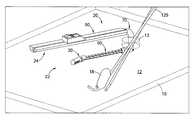
- FIGS. 1-3depict a medical system 20 for use intracorporeally to assist in surgical procedures beneath a tissue layer 10 .
- the tissue layer 10is typically that of a mammalian patient having a skin layer covering an bodily cavity 12 such as the abdominal or thoracic cavity having various organs 18 ( FIG. 11 ) therein.
- an bodily cavity 12such as the abdominal or thoracic cavity having various organs 18 ( FIG. 11 ) therein.
- the medical system 20may be employed with many different bodily cavities and bodily structures, and is not limited to those described or depicted herein.
- the medical system 20generally includes a distal portion 22 intended to be utilized beneath the tissue 10 and within the body cavity 12 , and a proximal portion 24 intended to reside above the tissue 10 and controlled by the medical professional or other user.
- the distal portion 22 of the medical system 20generally includes a camera head 30 that is connected to a translating beam 50 .
- the beam 50slidably attaches through a guide sheath 70 , part of which is also within the distal portion 22 .
- the guide sheath 70attaches to a handle 90 within the proximal portion 22 of the medical system 20 , which is utilized to orient and control translation of the beam 50 and camera head 30 .
- the medical system 20is generally intended to be used in conjunction with a port 14 positioned within an opening 13 ( FIG. 11 ) in the tissue 10 .
- the port 14has been depicted in FIG.
- the beam 50is a one-way bending beam which can bend through the angles formed by the guide sheath 70 to allow the system 20 to rotate through the tissue 10 and extend generally in the plane of the tissue 10 .
- the beam 50resists bending in one direction and is oriented relative to the guide sheath such that, as the beam is slid relative to guide sheath, the beam bends in a first direction (generally down on the page in FIGS.
- the beam 50is a cantilevered beam that is supported at the distal opening of the guide sheath 70 .
- the beam 50resists bending ‘downward’ under the force of gravity, assuming the system 20 and beam 50 are oriented appropriately relative to gravity, e.g. in most abdominal surgeries where the patient is in a supine or semi-supine position.
- the system 20may be utilized when the patient is in other positions or the system 20 and beam 50 are rotated such that the plane of the first and second directions is not perfectly perpendicular to the ground.
- the apparatus 20may also be rotated relative to the port 14 such that the distal portion 22 and its camera head 30 sweep through a plane generally parallel to the tissue 10 .
- the beam 50may be extended and retracted distally and proximally to position the camera head 30 within the cavity 12 .
- the camera head 30pivots relative to the beam 50 , and preferably provides for both rotation about an axis 16 defined by the beam 50 as well as pivoting about an axis transverse to the axis of the beam 50 . Accordingly, the medical system 20 provides 4 degrees of freedom to the camera head 30 for improved visualization and lighting throughout the body cavity 12 .
- the camera head 30generally includes a camera 32 and one or more lighting elements 34 . Additional elements such as an electro cautery device 36 or injection ports may be provided within the camera head 30 .
- the camera 32is an HD camera which utilizes laparoscope camera technology having rod-lens imaging and “chip-in-the-tip” imaging. Utilizing rod-lenses, the images from the cameral 32 are captured on a sensor within the camera head 30 or within the handle 90 .
- the lighting elements 34are preferably LED elements and provide illumination via a electrical connection with the handle 90 , or are lenses connected to a fiber optic cable carrying light from an external lamp, such as a Xenon arc lamp.
- the camera head 30generally includes a joint member 38 connecting a distal head portion 40 to a proximal head portion 42 .
- the joint 38is pivotally connected to the proximal head portion 42 , e.g. via a pin, ball-and-socket or other pivotal connection, to allow the joint 38 and the distal head portion 40 to pivot relative to the proximal head portion 42 and beam 50 .
- the joint 38also provides a flange 48 defining a surface about which the distal head portion 40 may rotate about the longitudinal axis of the joint 38 (and often axis 16 as shown).
- the pivoting and rotation of the camera head 30may be accomplished via appropriately located control wires 44 which pass through an interior passageway 46 of the joint 38 and through the interior of the beam 50 .
- the control wires 44may mechanically transfer energy to the camera head 34 for articulation, or the camera head 30 may include small motors or prime movers (not shown) that are electrically driven via electric control wires 44 .
- the beam 50is generally formed by a plurality of links 52 connected on one side by a flexible strip 54 .
- each of the links 52preferably includes a bore 56 which is aligned with adjacent bores 56 to form an internal passageway through the beam 50 leading between the camera head 30 and the handle 90 .
- One or more links 52 at the distal end of the beam 50is attached to the proximal head portion 42 of the camera head 30 .
- the links 52may be formed of plastic or metal, while the strip 54 is formed of a resilient but flexible material, preferably of nitinol or other biocompatible metal or alloy, although sufficiently resilient plastics can also be used.
- the flexible strip 54may be attached to the links 52 via an adhesive or using other bonding techniques such as fusion, soldering or welding at appropriate points to provide one-way bending.
- the strip 54may include lateral slots, preferably at axial positions spaced from the abutting corners of the links, to provide a location for soldering or to control the stiffness and flexibility of the strip 54 .
- the linksmay be attached to the strip 54 a by bending small tabs 53 a formed in the links, namely bending the tabs 53 a through the lateral slots 55 a and over the strip 54 a thereby locking the links in place.
- the beam 50does not flex more than 1 to 10 degrees from the straight linear axis 16 depicted in the figures. For example, in FIG.
- an alternate beam 150(shown from the side) includes a plurality of links 152 which are connected to a plurality of small strips 154 .
- the plurality of strips 154are positioned to extend over the abutting corners 158 defining by the abutting surfaces 160 of adjacent links 152 .
- the plurality of strips 154are flexible such that the lower corners 162 (i.e. those down on the page in FIG. 5 ) may move away from each other while the links 152 general pivot about the other edges 158 which are held together via the strips 154 .
- an alternate beam 250includes a plurality of links 252 that are pivotally connected together at their upper adjacent corners via corresponding tabs and detents 254 which provide a hinge joint.
- FIG. 7depicts an alternate beam 350 which includes a plurality of links 352 and each are pivotally attached at their upper corners to pins 354 which allow the links 352 to rotate relative to one another about the pins 354 .
- the corners of the upper surfaces 356are rounded (or chamfered, filleted, etc.) to accommodate the rotation, while the links include adjacent abutting surfaces 358 which extend below the pins 354 to prevent bending in the opposite direction (i.e. down on the page).
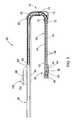
- the guide sheath 70is tubular and generally includes a first sheath portion 72 and a second sheath portion 74 .
- the first sheath portionis straight and defines a first axis (shown as coincident with axis 16 in FIG. 2 ), and likewise the second sheath portion 74 is generally straight and defines a second bend 75 .
- the first sheath portion 72is rotatable relative to the second sheath portion 74 about a hinge 76 to adjust the angle between the first and second axes.
- a control wire or other control member(not shown) is attached to the first sheath portion at a position distal to the hinge 76 to control articulation of the first sheath portion 72 between an introduction configuration and an operative configuration.
- the first sheath portion 72In the introduction configuration ( FIG. 8 ) the first sheath portion 72 is generally aligned with the second sheath portion 74 such that the first axis and second axis are generally parallel.
- the first axisis rotated relative to the second axis, preferably between 1 and 135 degrees and most preferably around 90 degrees.
- FIG. 2also shows that the first sheath portion 72 preferably includes plurality of projecting tabs 73 in an area of the hinge connection that are angularly spaced. The tabs 73 are sized and positioned to engage the second sheath portion 74 (or are otherwise operatively connected thereto) to provide for discrete angular positioning of the first sheath portion 72 relative to the second sheath portion 74 .
- a recess 78is formed in the first sheath portion 72 and a corresponding recess (not shown) in the second sheath portion 74 provides an open space for the beam 50 to pass through a first bend 75 formed between the first and second sheath portions 72 , 74 .
- a third portion 80 of the guide sheath 70 (at a proximal end thereof)further defines a second bend 82 .
- the second bendis fixed, such as by rigidly joining or unitarily forming the second and third sheath portions 74 , 80 , and is preferably around 90 degrees.
- the second bendcould also be a controllable pivoting joint.
- the beam 50rotates about 90 degrees through the second bend 82 , and then rotates another 90 degrees through the first bend 75 such that a distal portion of the beam 50 extends generally parallel to a proximal portion of the beam 50 that is external to the tissue 10 (as with the distal and proximal portions 22 , 24 of the system 20 described above).
- a proximal end 58 of the beam 50is attached to the handle 90 .
- the handle 90generally includes a housing 92 defining a guide rail 94 , which has been depicted as a simple slot 94 formed longitudinally through the housing 92 .
- a thumb slider 96slides along the housing 92 guided by the slot 94 , and includes a tab 98 projecting through the slot 94 and riding within the housing 92 .
- the tab 98is attached to the proximal end 58 of the beam 50 , i.e. to one or more proximal links 52 .
- the beam 50may be moved distally and proximally through the guide sheath 70 and within the body cavity 12 .
- the control wires 44 extending from the camera head 30 through the beam 50also extend through the thumb slider 96 to various controls 100 located on thereon.
- the controls 100may be operatively connected to a circuit board 102 or other electronic elements for transmitting and storing signals from the camera head 30 , or may be attaching to winding wheels, torque wheels, tensioning mechanisms and the like for transmitting mechanical energy through the control wires 44 (e.g. for rotation of the camera 32 ).
- FIGS. 8-10operation of the medical system 20 will be described.
- the medical system 20is shown in the introduction configuration where the thumb slider 96 of the handle 90 is moved proximally (to the left on the page) to retract the beam 50 .
- the beam 50extends through the second bend 82 of the guide sheath 70 and through both the first and second sheath portions 72 , 74 which are generally parallel.
- the angle of the second bend 82 , the angle of the first bend 75 (which can be greater than zero in the introduction configuration), and the size of the first and second sheath portions 72 , 74are configured relative to one another to allow the distal portion 22 of the medical system 20 to pass through the opening in the port 14 (or directly through the opening 13 in tissue 10 ).
- the first sheath portion 72may be rotated relative to the second sheath portion 74 such that the guide sheath 70 forms the first bend 75 , as shown in FIG. 9 .
- Rotation of the first sheath section 72causes the distal end of the beam 50 to be rotated a total of about 180 degrees relative to the proximal portion residing in the handle 90 .
- the entire handle assembly 90may be rotated about a plane of the tissue 10 and the camera head 30 rotated or pivoted to initially identify the structures within the cavity 12 .
- the beam 50may be slid through the guide sheath and distally projected as shown in FIG. 10 .
- the beam 50 and camera head 30project beyond a distal end of the guide sheath 70 and further into the cavity 12 .
- additional instruments 125may be passed through the port 14 or through other access points into the cavity 12 for performing surgery such as a laparoscopic or other minimally invasive surgery.
- the medical system 20provides a means for introducing a distal section 22 of the device within the bodily cavity 12 while a proximal portion of the device 24 remains above the tissue 10 while the two portions 22 , 24 are generally parallel to one another.
- This configurationis relatively unobtrusive to other instruments, and provides complete viewing of the cavity 12 by providing the camera 32 with 3 or 4 degrees of freedom.
- One of the advantages of the system 20is that the camera 30 is moved away from the immediate vicinity of the operating field and other instruments, so that the instruments may be viewed from a side-view rather than head-on. This is likely to be an ideal perspective for operative visualization.
- the guide sheath 70is generally depicted as performing a U-turn or bend in the operative configuration, it will be recognized that the pivotal connection between the first and second sheath portions 72 , 74 can be such that the beam 50 is not coplanar with the handle 90 or the portion of the beam therein, or such that the beam 50 follows one or more bends that form an S-shape or Z-turn.
- the camera head 30is provided with 4 degrees of freedom to find the best position within the cavity 12 to navigate around adjacent structures to illuminate and visualize an organ or other bodily structure 18 within the cavity 12 , while still providing sufficient space for additional medical instruments 125 to be inserted through the opening 13 and the tissue 10 for operation on the same bodily structure 18 .
- the articulation of the camera head 30allows any degree of triangulation between the additional instruments and the camera head pointing towards the target. Accordingly, the medical system 20 is especially adapted for minimally invasive surgery which utilizes a single incision or single port.
- the camera head 30includes side viewing camera 32 , although it can also be provided at the distal end of the distal head portion 40 .
- control wires 44need not extend through the beam 50 , and could be provided alongside the exterior of the beam 50 such that the plurality of links 52 may be solid.
- the thumb slider 96could be motorized, and further be electrically connected to a computer with proper software to control articulation of the slider 96 and translation of the beam 50 , as well as both mechanical and electrical control over camera head 30 and receipt of its visual information.
- the systems, devices and methodsmay be used on any layer of material (e.g. fabrics, cloth, polymers, elastomers, plastics and rubber) that may or may not be associated with a human or animal body and a bodily lumen.
- the systems, devices and methodscan find use in laboratory and industrial settings for placing devices through one or more layers of material that may or may not find application to the human or animal body, and likewise closing holes or perforations in layers of material that are not bodily tissue.
- Some examplesinclude viewing behind structures such as walls, plates, floors, rubble (e.g. in rescue work), as well as working with synthetic tissues, polymeric sheets, animal studies, veterinary applications, and post-mortem activities.
Landscapes
- Health & Medical Sciences (AREA)
- Life Sciences & Earth Sciences (AREA)
- Surgery (AREA)
- General Health & Medical Sciences (AREA)
- Public Health (AREA)
- Veterinary Medicine (AREA)
- Nuclear Medicine, Radiotherapy & Molecular Imaging (AREA)
- Animal Behavior & Ethology (AREA)
- Molecular Biology (AREA)
- Engineering & Computer Science (AREA)
- Biomedical Technology (AREA)
- Heart & Thoracic Surgery (AREA)
- Medical Informatics (AREA)
- Pathology (AREA)
- Biophysics (AREA)
- Radiology & Medical Imaging (AREA)
- Physics & Mathematics (AREA)
- Optics & Photonics (AREA)
- Rehabilitation Therapy (AREA)
- Endoscopes (AREA)
- Surgical Instruments (AREA)
Abstract
Description
Claims (29)
Priority Applications (5)
| Application Number | Priority Date | Filing Date | Title |
|---|---|---|---|
| US13/408,640US9339264B2 (en) | 2010-10-01 | 2012-02-29 | Port access visualization platform |
| EP13155705.0AEP2633799B1 (en) | 2012-02-29 | 2013-02-19 | Port access visualization platform |
| AU2013201155AAU2013201155B2 (en) | 2012-02-29 | 2013-02-25 | Port access visualization platform |
| JP2013035550AJP5666638B2 (en) | 2012-02-29 | 2013-02-26 | Medical system used in the body to support surgical operations performed below the tissue layer |
| US15/099,988US10076239B2 (en) | 2009-10-02 | 2016-04-15 | Port access visualization platform |
Applications Claiming Priority (2)
| Application Number | Priority Date | Filing Date | Title |
|---|---|---|---|
| US12/896,373US9232962B2 (en) | 2009-10-02 | 2010-10-01 | Apparatus for single port access |
| US13/408,640US9339264B2 (en) | 2010-10-01 | 2012-02-29 | Port access visualization platform |
Related Parent Applications (1)
| Application Number | Title | Priority Date | Filing Date |
|---|---|---|---|
| US12/896,373Continuation-In-PartUS9232962B2 (en) | 2009-10-02 | 2010-10-01 | Apparatus for single port access |
Related Child Applications (1)
| Application Number | Title | Priority Date | Filing Date |
|---|---|---|---|
| US15/099,988ContinuationUS10076239B2 (en) | 2009-10-02 | 2016-04-15 | Port access visualization platform |
Publications (2)
| Publication Number | Publication Date |
|---|---|
| US20120209070A1 US20120209070A1 (en) | 2012-08-16 |
| US9339264B2true US9339264B2 (en) | 2016-05-17 |
Family
ID=46637401
Family Applications (2)
| Application Number | Title | Priority Date | Filing Date |
|---|---|---|---|
| US13/408,640Active2033-09-03US9339264B2 (en) | 2009-10-02 | 2012-02-29 | Port access visualization platform |
| US15/099,988Active2030-10-31US10076239B2 (en) | 2009-10-02 | 2016-04-15 | Port access visualization platform |
Family Applications After (1)
| Application Number | Title | Priority Date | Filing Date |
|---|---|---|---|
| US15/099,988Active2030-10-31US10076239B2 (en) | 2009-10-02 | 2016-04-15 | Port access visualization platform |
Country Status (4)
| Country | Link |
|---|---|
| US (2) | US9339264B2 (en) |
| EP (1) | EP2633799B1 (en) |
| JP (1) | JP5666638B2 (en) |
| AU (1) | AU2013201155B2 (en) |
Cited By (4)
| Publication number | Priority date | Publication date | Assignee | Title |
|---|---|---|---|---|
| US20160227995A1 (en)* | 2009-10-02 | 2016-08-11 | Cook Medical Technologies Llc | Port access visualization platform |
| US10849483B2 (en) | 2014-09-15 | 2020-12-01 | Vivid Medical, Inc. | Single-use, port deployable articulating endoscope |
| US11284918B2 (en) | 2012-05-14 | 2022-03-29 | Cilag GmbH Inlernational | Apparatus for introducing a steerable camera assembly into a patient |
| US11399834B2 (en) | 2008-07-14 | 2022-08-02 | Cilag Gmbh International | Tissue apposition clip application methods |
Families Citing this family (14)
| Publication number | Priority date | Publication date | Assignee | Title |
|---|---|---|---|---|
| WO2011041668A1 (en)* | 2009-10-02 | 2011-04-07 | Wilson-Cook Medical, Inc. | Endoscopic fascia tunneling |
| US10098527B2 (en)* | 2013-02-27 | 2018-10-16 | Ethidcon Endo-Surgery, Inc. | System for performing a minimally invasive surgical procedure |
| DE102013211698B4 (en)* | 2013-06-20 | 2017-07-06 | Fraunhofer-Gesellschaft zur Förderung der angewandten Forschung e.V. | Endoabdominal camera system |
| CN104939800B (en)* | 2015-06-16 | 2017-04-05 | 西南医科大学附属医院 | A kind of the intestines and stomach automatic detection surgery apparatus |
| US10850046B2 (en)* | 2016-03-28 | 2020-12-01 | Becton, Dickinson And Company | Cannula locator device |
| WO2019215354A1 (en)* | 2018-05-09 | 2019-11-14 | Andres Del Amor Arroyo Tristan | Endoscope video camera head which can be attached to a surgical wound protector, without a rigid tube or manual support |
| ES2730387B2 (en)* | 2018-05-09 | 2020-10-01 | Tristan Andres Del Amor Arroyo | ENDOSCOPIC CAMERA HEAD ATTACHED TO SURGICAL WOUND PROTECTOR, WITHOUT RIGID TUBE OR MANUAL RESTRAINT |
| JP7256848B2 (en)* | 2019-04-04 | 2023-04-12 | グリー株式会社 | Program, control method and computer |
| WO2021152756A1 (en)* | 2020-01-30 | 2021-08-05 | 三菱重工業株式会社 | Non-destructive inspection device and non-destructive inspection method |
| DE102020132776A1 (en)* | 2020-12-09 | 2022-06-09 | Karl Storz Se & Co. Kg | Hybrid endoscope with rotating drum for sterile medical applications |
| US20240033020A1 (en)* | 2020-12-16 | 2024-02-01 | Robeaute | Delivery and gathering system comprising a microrobot |
| EP4066770A1 (en)* | 2021-04-02 | 2022-10-05 | Robeaute | Delivery and gathering system comprising a microrobot |
| US20220395171A1 (en)* | 2021-06-15 | 2022-12-15 | Arthrex, Inc. | Surgical camera system |
| US12259086B2 (en)* | 2022-11-23 | 2025-03-25 | Becton, Dickinson And Company | Adjustable image capture device |
Citations (128)
| Publication number | Priority date | Publication date | Assignee | Title |
|---|---|---|---|---|
| US3677262A (en) | 1970-07-23 | 1972-07-18 | Henry J Zukowski | Surgical instrument illuminating endotracheal tube inserter |
| US3690775A (en)* | 1971-09-01 | 1972-09-12 | Avco Corp | Borescope fixture |
| US3778170A (en)* | 1972-11-02 | 1973-12-11 | Gen Electric | Borescope guide tube |
| US4222382A (en)* | 1979-01-26 | 1980-09-16 | Massachusetts Institute Of Technology | Femoral component hip joint prosthesis extractor |
| US4254763A (en) | 1979-06-07 | 1981-03-10 | Codman & Shurtleff, Inc. | Surgical retractor assembly |
| GB2031281B (en) | 1978-10-12 | 1982-12-15 | Yoshida H | Support device for medical instruments |
| US4640124A (en)* | 1984-02-16 | 1987-02-03 | Richard Wolf Gmbh | Tecnoscopes |
| US4911148A (en)* | 1989-03-14 | 1990-03-27 | Intramed Laboratories, Inc. | Deflectable-end endoscope with detachable flexible shaft assembly |
| US5133336A (en)* | 1990-10-22 | 1992-07-28 | Endoscopy Support Services, Inc. | Disposable liquid supply system for use in an endoscope |
| US5522788A (en)* | 1994-10-26 | 1996-06-04 | Kuzmak; Lubomyr I. | Finger-like laparoscopic blunt dissector device |
| US5643221A (en)* | 1990-05-04 | 1997-07-01 | Bullard; James Roger | Controlled targeting laryngoscope |
| US5976075A (en)* | 1997-12-15 | 1999-11-02 | University Of Massachusetts | Endoscope deployment apparatus |
| US6416469B1 (en) | 2000-01-26 | 2002-07-09 | Genzyme Corporation | Suture organizing and retaining device and base member for surgical retractor |
| US6539942B2 (en)* | 2001-04-19 | 2003-04-01 | Richard Schwartz | Endotracheal intubation device |
| US20040230095A1 (en) | 2003-05-16 | 2004-11-18 | David Stefanchik | Medical apparatus for use with an endoscope |
| US20050096508A1 (en) | 1999-10-18 | 2005-05-05 | Valerio Valentini | Adjustable surgical retractor |
| US20060004369A1 (en) | 2004-06-17 | 2006-01-05 | Scimed Life Systems, Inc. | Slidable sheaths for tissue removal devices |
| US20070055108A1 (en) | 1996-02-20 | 2007-03-08 | Taylor Charles S | Surgical instruments and procedures for stabilizing the beating heart during coronary artery bypass graft surgery |
| US20070167682A1 (en)* | 2004-04-21 | 2007-07-19 | Acclarent, Inc. | Endoscopic methods and devices for transnasal procedures |
| US20070244362A1 (en)* | 2006-04-12 | 2007-10-18 | Roger El-Hachem | Segmented colonoscope |
| US20080051802A1 (en)* | 2006-08-10 | 2008-02-28 | Novineon Healthcare Technology Partners Gmbh | Medical instrument |
| US20080132758A1 (en)* | 2006-12-05 | 2008-06-05 | Ethicon Endo-Surgery, Inc. | Independent Articulating Accessory Channel |
| US20080208001A1 (en)* | 2007-02-26 | 2008-08-28 | Ron Hadani | Conforming endoscope |
| US20080287741A1 (en)* | 2007-05-18 | 2008-11-20 | Boston Scientific Scimed, Inc. | Articulating torqueable hollow device |
| US20080287743A1 (en) | 2007-05-17 | 2008-11-20 | Boston Scientific Scimed, Inc. | Medical retractor and stabilizing assembly and related methods of use |
| US20080300547A1 (en) | 2007-06-01 | 2008-12-04 | Bakos Gregory J | Integrated securement and closure apparatus |
| US20080319258A1 (en) | 2005-07-15 | 2008-12-25 | Thompson Christopher C | Sterile Access Conduit |
| US20090054728A1 (en) | 2007-08-21 | 2009-02-26 | Trusty Robert M | Manipulatable guide system and methods for natural orifice translumenal endoscopic surgery |
| US20090143643A1 (en) | 2007-10-05 | 2009-06-04 | Weitzner Barry D | Transluminal endoscopic surgery kit |
| US20090149714A1 (en) | 2007-12-05 | 2009-06-11 | Frank Bonadio | Surgical devices and methods |
| US7553277B2 (en)* | 2005-08-31 | 2009-06-30 | Karl Storz Gmbh & Co. Kg | Endoscope with variable direction of view |
| US20090171151A1 (en)* | 2004-06-25 | 2009-07-02 | Choset Howard M | Steerable, follow the leader device |
| US20090192465A1 (en) | 2008-01-30 | 2009-07-30 | Tyco Healthcare Group Lp | Access assembly with spherical valve |
| US7575548B2 (en) | 2004-09-24 | 2009-08-18 | Olympus Corporation | Endoscopic treatment instrument, endoscopic treatment system and supporting adaptor |
| US20090259172A1 (en) | 2008-04-09 | 2009-10-15 | Koji Yamaoka | Over tube |
| US20090276055A1 (en) | 2008-05-01 | 2009-11-05 | Ethicon Endo-Surgery, Inc. | Method for gastric volume reduction surgery |
| US20090275798A1 (en) | 2008-05-01 | 2009-11-05 | Olympus Medical Systems Corp. | Overtube and endoscope system suitable for treatment such as submucosal dissection |
| US20090275967A1 (en) | 2008-05-01 | 2009-11-05 | Ethicon Endo-Surgery, Inc. | Safe tissue puncture device |
| US20100010298A1 (en) | 2008-07-14 | 2010-01-14 | Ethicon Endo-Surgery, Inc. | Endoscopic translumenal flexible overtube |
| US20100010299A1 (en) | 2008-07-14 | 2010-01-14 | Ethicon Endo-Surgery, Inc. | Endoscopic translumenal articulatable steerable overtube |
| US7658738B2 (en) | 2004-05-14 | 2010-02-09 | Ethicon Endo-Surgery, Inc. | Medical devices for use with endoscope |
| US20100036200A1 (en) | 2007-04-12 | 2010-02-11 | Olympus Corporation | Body insertion instrument |
| US20100042078A1 (en) | 2007-05-16 | 2010-02-18 | Olympus Corporation | Intra-body-cavity insertion instrument guide and intra-body-cavity insertion instrument guide system |
| US20100049162A1 (en) | 2008-08-20 | 2010-02-25 | Chest Innovations, Inc. | Mediastinoscopy access, sampling, and visualization kit featuring toroidal balloons and exotracheal method of using |
| US20100063359A1 (en) | 2007-04-11 | 2010-03-11 | Tyco Healthcare Group Lp | Endoscopic/laparoscopic introducer sleeve |
| US20100063358A1 (en) | 2006-07-07 | 2010-03-11 | Fred Kessler | Channeled flexible sleeve for medical articles |
| US20100081863A1 (en) | 2008-09-30 | 2010-04-01 | Ethicon Endo-Surgery, Inc. | Methods and devices for performing gastrectomies and gastroplasties |
| US20100081882A1 (en) | 2008-09-30 | 2010-04-01 | Ethicon Endo-Surgery, Inc. | Multiple Port Surgical Access Device |
| US20100081880A1 (en) | 2008-09-30 | 2010-04-01 | Ethicon Endo-Surgery, Inc. | Surgical Access Device |
| US20100081883A1 (en) | 2008-09-30 | 2010-04-01 | Ethicon Endo-Surgery, Inc. | Methods and devices for performing gastroplasties using a multiple port access device |
| US20100081881A1 (en) | 2008-09-30 | 2010-04-01 | Ethicon Endo-Surgery, Inc. | Surgical Access Device with Protective Element |
| US20100081995A1 (en) | 2008-09-30 | 2010-04-01 | Ethicon Endo-Surgery, Inc. | Variable Surgical Access Device |
| US20100081877A1 (en) | 2008-10-01 | 2010-04-01 | Ethicon Endo-Surgery, Inc. | Overtube with expandable tip |
| US20100081871A1 (en) | 2008-09-30 | 2010-04-01 | Ethicon Endo-Surgery, Inc. | Surgical access device with flexible seal channel |
| US20100094284A1 (en) | 2006-03-08 | 2010-04-15 | Olympus Medical Systems Corp. | Organ incision method |
| US20100114033A1 (en) | 2008-11-06 | 2010-05-06 | Tyco Healthcare Group Lp | Surgical access device |
| US7717847B2 (en) | 2004-04-05 | 2010-05-18 | Tyco Healthcare Group Lp | Surgical hand access apparatus |
| US20100130817A1 (en) | 2008-11-25 | 2010-05-27 | Ethicon Endo-Surgery, Inc. | Tissue manipulation devices |
| US20100152539A1 (en) | 2008-12-17 | 2010-06-17 | Ethicon Endo-Surgery, Inc. | Positionable imaging medical devices |
| US20100160729A1 (en) | 2008-12-19 | 2010-06-24 | Smith Paul J | Systems and methods for directing instruments to varying positions at the distal end of a guide tube |
| US20100160735A1 (en) | 2008-12-18 | 2010-06-24 | Ethicon Endo-Surgery, Inc. | Steerable surgical access devices and methods |
| US20100168519A1 (en) | 2005-02-14 | 2010-07-01 | Olympus Corporation | Endoscope Flexible Tube and Endoscope Device |
| US20100168522A1 (en) | 2008-10-23 | 2010-07-01 | Thomas Wenchell | Surgical access assembly |
| US7749198B2 (en) | 2007-05-22 | 2010-07-06 | Tyco Healthcare Group Lp | Surgical portal apparatus with variable adjustment |
| US7753901B2 (en) | 2004-07-21 | 2010-07-13 | Tyco Healthcare Group Lp | Laparoscopic instrument and cannula assembly and related surgical method |
| US7762990B2 (en) | 2007-05-24 | 2010-07-27 | Tyco Healthcare Group Lp | Surgical access apparatus with centering mechanism |
| US7766810B2 (en) | 2005-03-10 | 2010-08-03 | Olympus Medical Systems Corp. | Probing method and holding method for luminal organ |
| US20100210912A1 (en) | 2009-02-17 | 2010-08-19 | Tyco Healthcare Group Lp | Access port with suture management system including flapper with inserts |
| US20100211012A1 (en) | 2009-02-17 | 2010-08-19 | Tyco Healthcare Group Lp | Port fixation with filament actuating member |
| US20100211084A1 (en) | 2009-02-18 | 2010-08-19 | Tyco Healthcare Group Lp | Suture management system for surgical portal apparatus including numbered clips |
| US20100222747A1 (en) | 2003-04-25 | 2010-09-02 | Tyco Healthcare Group Lp | Surgical access apparatus |
| US20100228091A1 (en) | 2009-03-06 | 2010-09-09 | Ethicon Endo-Surgery, Inc. | Methods and devices for providing access into a body cavity |
| US20100228096A1 (en) | 2009-03-06 | 2010-09-09 | Ethicon Endo-Surgery, Inc. | Methods and devices for providing access into a body cavity |
| US20100228198A1 (en) | 2009-03-06 | 2010-09-09 | Ethicon Endo-Surgery, Inc. | Methods and devices for providing access into a body cavity |
| US20100228092A1 (en) | 2009-03-06 | 2010-09-09 | Ethicon Endo-Surgery, Inc. | Surgical access devices and methods providing seal movement in predefined paths |
| US20100228094A1 (en) | 2009-03-06 | 2010-09-09 | Ethicon Endo-Surgery, Inc. | Surgical access devices and methods providing seal movement in predefined movement regions |
| US20100228090A1 (en) | 2009-03-06 | 2010-09-09 | Ethicon Endo-Surgery, Inc. | Methods and devices for providing access into a body cavity |
| US20100234806A1 (en) | 2009-03-10 | 2010-09-16 | Tyco Healthcare Group Lp | Port fixation using expandable threads |
| US20100234688A1 (en) | 2009-03-10 | 2010-09-16 | Tyco Healthcare Group Lp | Access port including multi-layer seal and suture parks |
| US7798998B2 (en) | 2006-10-06 | 2010-09-21 | Surgiquest, Inc. | Elastically deformable surgical access device |
| US20100241078A1 (en) | 2009-03-19 | 2010-09-23 | Tyco Healthcare Group Lp | Surgical port seal |
| US20100240960A1 (en) | 2009-03-20 | 2010-09-23 | Tyco Healthcare Group Lp | Flexible port seal |
| US20100249515A1 (en) | 2009-03-31 | 2010-09-30 | Tyco Healthcare Group Lp | Access portal including silicone foam three layer seal |
| US20100249498A1 (en) | 2009-03-24 | 2010-09-30 | Tyco Healthcare Group Lp | Endoscopic Apparatus for Manipulating Tissue |
| US20100249525A1 (en) | 2009-03-31 | 2010-09-30 | Ethicon Endo-Surgery, Inc. | Devices and methods for providing access into a body cavity |
| US20100249810A1 (en) | 2009-03-24 | 2010-09-30 | Tyco Healthcare Group Lp | Suture management system for surgical portal apparatus including slotted ring |
| US20100249708A1 (en) | 2009-03-26 | 2010-09-30 | Tyco Healthcare Group Lp | Articulating surgical portal apparatus with spring |
| US20100249711A1 (en) | 2009-03-30 | 2010-09-30 | Tyco Healthcare Group Lp | Surgical access apparatus with seal and closure valve assembly |
| US20100249709A1 (en) | 2009-03-27 | 2010-09-30 | Tyco Healthcare Group Lp | Surgical access assembly including shield member |
| US7806870B2 (en) | 2006-10-06 | 2010-10-05 | Surgiquest, Incorporated | Elastically deformable surgical access device having telescoping guide tube |
| US20100256636A1 (en) | 2006-04-29 | 2010-10-07 | Raul Fernandez | Devices for Use in Transluminal and Endoluminal Surgery |
| US20100256453A1 (en) | 2009-04-02 | 2010-10-07 | Tyco Healthcare Group Lp | Access portal including sponge |
| US20100256567A1 (en) | 2005-04-25 | 2010-10-07 | Tyco Healthcare Group Lp | Surgical portal with seal system |
| US20100256447A1 (en) | 2007-09-24 | 2010-10-07 | Shay Dubi | Virtual channel enabling device for use in endoscopic instrument insertion and body cavity cleansing |
| US20100262080A1 (en) | 2009-04-08 | 2010-10-14 | Ethicon Endo-Surgery, Inc. | Surgical access device having removable and replaceable components |
| US20100261974A1 (en)* | 2009-04-08 | 2010-10-14 | Ethicon Endo-Surgery, Inc. | Methods and devices for providing access into a body cavity |
| US20100261969A1 (en) | 2009-04-14 | 2010-10-14 | Tyco Healthcare Group Lp | Vibrating seal for a surgical trocar apparatus |
| US20100261962A1 (en) | 2007-03-21 | 2010-10-14 | Friedberg Joseph S | Natural orifice transluminal endoscopic surgery overtube and method of introducing multiple endoscopes |
| US20100261975A1 (en) | 2009-03-06 | 2010-10-14 | Ethicon Endo-Surgery, Inc. | Methods and devices for accessing a body cavity |
| US20100261976A1 (en) | 2009-04-14 | 2010-10-14 | Tyco Healthcare Group Lp | Apparatus and System for Performing Surgery |
| US7815565B2 (en) | 2003-05-16 | 2010-10-19 | Ethicon Endo-Surgery, Inc. | Endcap for use with an endoscope |
| US20100268162A1 (en) | 2009-04-15 | 2010-10-21 | Ethicon Endo-Surgery, Inc. | Cannula with sealing elements |
| US20100274093A1 (en) | 2009-04-22 | 2010-10-28 | Ethicon Endo-Surgery, Inc. | Methods and devices for identifying sealing port size |
| US20100280327A1 (en) | 2009-05-04 | 2010-11-04 | Ethicon Endo-Surgery, Inc. | Methods and devices for providing access through tissue to a surgical site |
| US20100286483A1 (en) | 2009-05-06 | 2010-11-11 | Tyco Healthcare Group Lp | Surgical portal device |
| US20100286478A1 (en) | 2009-04-23 | 2010-11-11 | Usgi Medical, Inc. | Flexible surgery access systems |
| US20100286484A1 (en) | 2009-05-07 | 2010-11-11 | Tyco Healthcare Group Lp | Flexible access assembly with multiple ports |
| US20100298775A1 (en) | 2009-05-21 | 2010-11-25 | Tyco Healthcare Group Lp | Access sheath with central seal |
| US20100298646A1 (en) | 2009-05-19 | 2010-11-25 | Tyco Healthcare Group Lp | Flexible access assembly with reinforced lumen |
| US20100312060A1 (en) | 2009-06-05 | 2010-12-09 | Ethicon Endo-Surgery, Inc. | Interlocking seal components |
| US20100312063A1 (en) | 2009-06-05 | 2010-12-09 | Ethicon Endo-Surgery, Inc. | Methods and devices for accessing a body cavity using a surgical access device with modular seal components |
| US20100312065A1 (en) | 2009-06-05 | 2010-12-09 | Ethicon Endo-Surgery, Inc. | Active seal components |
| US20100312061A1 (en) | 2009-06-05 | 2010-12-09 | Ethicon Endo-Surgery, Inc. | Methods and devices for providing access through tissue to a surgical site |
| US20110021877A1 (en) | 2009-07-24 | 2011-01-27 | Tyco Healthcare Group Lp | Surgical port and frangible introducer assembly |
| US20110028793A1 (en) | 2009-07-30 | 2011-02-03 | Ethicon Endo-Surgery, Inc. | Methods and devices for providing access into a body cavity |
| US20110028795A1 (en) | 2009-07-29 | 2011-02-03 | Tyco Healthcare Group Lp | Surgical portal device including textured surface |
| US20110028794A1 (en) | 2009-07-30 | 2011-02-03 | Ethicon Endo-Surgery, Inc. | Methods and devices for providing access into a body cavity |
| US20110028891A1 (en) | 2009-07-31 | 2011-02-03 | Tyco Healthcare Group Lp | Single Port Device Having Integral Filter/Vent |
| US20110034947A1 (en) | 2009-08-06 | 2011-02-10 | Tyco Healthcare Group Lp | Surgical device having a port with an undercut |
| US20110034778A1 (en) | 2009-08-06 | 2011-02-10 | Tyco Healthcare Group Lp | Elongated seal anchor for use in surgical procedures |
| US20110034935A1 (en) | 2009-08-06 | 2011-02-10 | Tyco Healthcare Group Lp | Surgical device having non-circular cross-section |
| US7955254B2 (en)* | 2006-04-07 | 2011-06-07 | Olympus Winter & Ibe Gmbh | Medical videoscope with a pivotably adjustable end part |
| US20110144590A1 (en)* | 2009-12-11 | 2011-06-16 | Ethicon Endo-Surgery, Inc. | Methods and devices for providing access through tissue to a surgical site |
| US7963976B2 (en)* | 2004-11-04 | 2011-06-21 | Dynamic Surgical Inventions, Llc | Articulated surgical probe and method for use |
| US20110196204A1 (en)* | 2010-02-11 | 2011-08-11 | Al Medical Devices, Inc. | Shape-conforming intubation device |
| US20110257637A1 (en)* | 2008-11-27 | 2011-10-20 | Q Medical International Ag | Instrument for laparoscopic surgery |
| US20120312103A1 (en)* | 2009-11-10 | 2012-12-13 | Kerstin Hannott | Inspection device and method for positioning an inspection device |
| US8616526B2 (en)* | 2008-12-02 | 2013-12-31 | Swisscom Ag | Insertion device for a cable in an existing pipe network |
Family Cites Families (37)
| Publication number | Priority date | Publication date | Assignee | Title |
|---|---|---|---|---|
| US11025A (en)* | 1854-06-06 | litta | ||
| US3858577A (en) | 1974-04-05 | 1975-01-07 | Univ Southern California | Fiber optic laser light delivery system |
| GB2147210B (en) | 1983-09-28 | 1986-12-17 | Wolf Gmbh Richard | An endoscope |
| US4640273A (en) | 1985-05-08 | 1987-02-03 | E-Z-Em, Inc. | Mouth guard for use with a diagnostic instrument |
| JPH0546406Y2 (en)* | 1988-07-20 | 1993-12-06 | ||
| US5716327A (en) | 1991-05-29 | 1998-02-10 | Origin Medsystems, Inc. | Body wall retraction system for wide cavity retraction |
| MX9202604A (en) | 1991-05-29 | 1994-05-31 | Origin Medsystems Inc | APPARATUS FOR MECHANICAL PROPERTY RETRACTION AND METHODS OF USE. |
| US5571215A (en) | 1993-02-22 | 1996-11-05 | Heartport, Inc. | Devices and methods for intracardiac procedures |
| JPH05123287A (en)* | 1991-11-08 | 1993-05-21 | Olympus Optical Co Ltd | Protective sheath |
| JP3147318B2 (en)* | 1992-08-26 | 2001-03-19 | オリンパス光学工業株式会社 | Forward scan type internal ultrasound probe |
| US5469853A (en) | 1992-12-11 | 1995-11-28 | Tetrad Corporation | Bendable ultrasonic probe and sheath for use therewith |
| US5547458A (en) | 1994-07-11 | 1996-08-20 | Ethicon, Inc. | T-shaped abdominal wall lift with telescoping member |
| US5512035A (en)* | 1994-10-27 | 1996-04-30 | Circon Corporation, A Delaware Corporation | Cable compensating mechanism for an endoscope |
| US5749889A (en) | 1996-02-13 | 1998-05-12 | Imagyn Medical, Inc. | Method and apparatus for performing biopsy |
| US6196968B1 (en)* | 1997-06-02 | 2001-03-06 | General Surgical Innovations, Inc. | Direct vision subcutaneous tissue retractor and method for use |
| US5913818A (en) | 1997-06-02 | 1999-06-22 | General Surgical Innovations, Inc. | Vascular retractor |
| JP4121615B2 (en) | 1997-10-31 | 2008-07-23 | オリンパス株式会社 | Endoscope |
| DE19906191A1 (en) | 1999-02-15 | 2000-08-17 | Ingo F Herrmann | Mouldable endoscope for transmitting light and images with supplementary device has non-round cross section along longitudinal section for inserting in human or animal body opening |
| US6530929B1 (en) | 1999-10-20 | 2003-03-11 | Sdgi Holdings, Inc. | Instruments for stabilization of bony structures |
| US6235028B1 (en) | 2000-02-14 | 2001-05-22 | Sdgi Holdings, Inc. | Surgical guide rod |
| US6528908B1 (en)* | 2001-10-09 | 2003-03-04 | Rick Lee | Induction drive for induction driven conveyor including a virtual continuous magnetic body and method of driving induction driven conveyor including a virtual continuous magnetic body |
| US7615003B2 (en) | 2005-05-13 | 2009-11-10 | Ethicon Endo-Surgery, Inc. | Track for medical devices |
| JP3521910B1 (en) | 2003-05-29 | 2004-04-26 | 清輝 司馬 | External forceps channel device for endoscope |
| FR2879914B1 (en) | 2004-12-24 | 2007-03-09 | Protomed Sarl | INTESTINAL RETRACTOR RETRACTOR FOR COELIOSCOPIC SURGERY |
| CA2630215A1 (en)* | 2005-11-17 | 2007-05-24 | Micromuscle Ab | Medical devices and methods for their fabrication and use |
| US7520879B2 (en) | 2006-02-07 | 2009-04-21 | Warsaw Orthopedic, Inc. | Surgical instruments and techniques for percutaneous placement of spinal stabilization elements |
| WO2007097034A1 (en)* | 2006-02-27 | 2007-08-30 | Olympus Medical Systems Corp. | Endoscope surgery operation instrument |
| US7841980B2 (en)* | 2006-05-11 | 2010-11-30 | Olympus Medical Systems Corp. | Treatment system, trocar, treatment method and calibration method |
| JP5226197B2 (en)* | 2006-08-25 | 2013-07-03 | オリンパス株式会社 | Endoscope guide tube and endoscope apparatus |
| JP5021346B2 (en)* | 2007-03-23 | 2012-09-05 | オリンパス株式会社 | Endoscope guide tube and endoscope apparatus |
| GB0716672D0 (en)* | 2007-08-28 | 2007-10-03 | Aircraft Medical Ltd | Laryngoscope |
| US7553227B2 (en) | 2007-10-31 | 2009-06-30 | Cnh America Llc | Residue splitter |
| JP5276998B2 (en)* | 2009-01-08 | 2013-08-28 | オリンパス株式会社 | Endoscope insertion aid |
| US9339264B2 (en) | 2010-10-01 | 2016-05-17 | Cook Medical Technologies Llc | Port access visualization platform |
| WO2011041669A1 (en)* | 2009-10-02 | 2011-04-07 | Wilson-Cook Medical, Inc. | Apparatus for single port access |
| JP2011172766A (en)* | 2010-02-24 | 2011-09-08 | Fujifilm Corp | Torque transmission device |
| US9795765B2 (en)* | 2010-04-09 | 2017-10-24 | St. Jude Medical International Holding S.À R.L. | Variable stiffness steering mechanism for catheters |
- 2012
- 2012-02-29USUS13/408,640patent/US9339264B2/enactiveActive
- 2013
- 2013-02-19EPEP13155705.0Apatent/EP2633799B1/enactiveActive
- 2013-02-25AUAU2013201155Apatent/AU2013201155B2/enactiveActive
- 2013-02-26JPJP2013035550Apatent/JP5666638B2/enactiveActive
- 2016
- 2016-04-15USUS15/099,988patent/US10076239B2/enactiveActive
Patent Citations (133)
| Publication number | Priority date | Publication date | Assignee | Title |
|---|---|---|---|---|
| US3677262A (en) | 1970-07-23 | 1972-07-18 | Henry J Zukowski | Surgical instrument illuminating endotracheal tube inserter |
| US3690775A (en)* | 1971-09-01 | 1972-09-12 | Avco Corp | Borescope fixture |
| US3778170A (en)* | 1972-11-02 | 1973-12-11 | Gen Electric | Borescope guide tube |
| GB2031281B (en) | 1978-10-12 | 1982-12-15 | Yoshida H | Support device for medical instruments |
| US4222382A (en)* | 1979-01-26 | 1980-09-16 | Massachusetts Institute Of Technology | Femoral component hip joint prosthesis extractor |
| US4254763A (en) | 1979-06-07 | 1981-03-10 | Codman & Shurtleff, Inc. | Surgical retractor assembly |
| GB2052996B (en) | 1979-06-07 | 1983-04-27 | Codman & Shurtleff | Surgical retractor assembly |
| US4640124A (en)* | 1984-02-16 | 1987-02-03 | Richard Wolf Gmbh | Tecnoscopes |
| US4911148A (en)* | 1989-03-14 | 1990-03-27 | Intramed Laboratories, Inc. | Deflectable-end endoscope with detachable flexible shaft assembly |
| US5643221A (en)* | 1990-05-04 | 1997-07-01 | Bullard; James Roger | Controlled targeting laryngoscope |
| US5133336A (en)* | 1990-10-22 | 1992-07-28 | Endoscopy Support Services, Inc. | Disposable liquid supply system for use in an endoscope |
| US5522788A (en)* | 1994-10-26 | 1996-06-04 | Kuzmak; Lubomyr I. | Finger-like laparoscopic blunt dissector device |
| US20070055108A1 (en) | 1996-02-20 | 2007-03-08 | Taylor Charles S | Surgical instruments and procedures for stabilizing the beating heart during coronary artery bypass graft surgery |
| US5976075A (en)* | 1997-12-15 | 1999-11-02 | University Of Massachusetts | Endoscope deployment apparatus |
| US20050096508A1 (en) | 1999-10-18 | 2005-05-05 | Valerio Valentini | Adjustable surgical retractor |
| US6416469B1 (en) | 2000-01-26 | 2002-07-09 | Genzyme Corporation | Suture organizing and retaining device and base member for surgical retractor |
| US6539942B2 (en)* | 2001-04-19 | 2003-04-01 | Richard Schwartz | Endotracheal intubation device |
| US20100222747A1 (en) | 2003-04-25 | 2010-09-02 | Tyco Healthcare Group Lp | Surgical access apparatus |
| US20040230095A1 (en) | 2003-05-16 | 2004-11-18 | David Stefanchik | Medical apparatus for use with an endoscope |
| US7815565B2 (en) | 2003-05-16 | 2010-10-19 | Ethicon Endo-Surgery, Inc. | Endcap for use with an endoscope |
| US7717847B2 (en) | 2004-04-05 | 2010-05-18 | Tyco Healthcare Group Lp | Surgical hand access apparatus |
| US20070167682A1 (en)* | 2004-04-21 | 2007-07-19 | Acclarent, Inc. | Endoscopic methods and devices for transnasal procedures |
| US7658738B2 (en) | 2004-05-14 | 2010-02-09 | Ethicon Endo-Surgery, Inc. | Medical devices for use with endoscope |
| US20060004369A1 (en) | 2004-06-17 | 2006-01-05 | Scimed Life Systems, Inc. | Slidable sheaths for tissue removal devices |
| US20090171151A1 (en)* | 2004-06-25 | 2009-07-02 | Choset Howard M | Steerable, follow the leader device |
| US7753901B2 (en) | 2004-07-21 | 2010-07-13 | Tyco Healthcare Group Lp | Laparoscopic instrument and cannula assembly and related surgical method |
| US20100222643A1 (en) | 2004-07-21 | 2010-09-02 | Tyco Healthcare Group Lp | Laparoscopic instrument and cannula assembly and related surgical method |
| US7575548B2 (en) | 2004-09-24 | 2009-08-18 | Olympus Corporation | Endoscopic treatment instrument, endoscopic treatment system and supporting adaptor |
| US7963976B2 (en)* | 2004-11-04 | 2011-06-21 | Dynamic Surgical Inventions, Llc | Articulated surgical probe and method for use |
| US20100168519A1 (en) | 2005-02-14 | 2010-07-01 | Olympus Corporation | Endoscope Flexible Tube and Endoscope Device |
| US7766810B2 (en) | 2005-03-10 | 2010-08-03 | Olympus Medical Systems Corp. | Probing method and holding method for luminal organ |
| US20100256567A1 (en) | 2005-04-25 | 2010-10-07 | Tyco Healthcare Group Lp | Surgical portal with seal system |
| US20080319258A1 (en) | 2005-07-15 | 2008-12-25 | Thompson Christopher C | Sterile Access Conduit |
| US7553277B2 (en)* | 2005-08-31 | 2009-06-30 | Karl Storz Gmbh & Co. Kg | Endoscope with variable direction of view |
| US20100094284A1 (en) | 2006-03-08 | 2010-04-15 | Olympus Medical Systems Corp. | Organ incision method |
| US7955254B2 (en)* | 2006-04-07 | 2011-06-07 | Olympus Winter & Ibe Gmbh | Medical videoscope with a pivotably adjustable end part |
| US20070244362A1 (en)* | 2006-04-12 | 2007-10-18 | Roger El-Hachem | Segmented colonoscope |
| US20100256636A1 (en) | 2006-04-29 | 2010-10-07 | Raul Fernandez | Devices for Use in Transluminal and Endoluminal Surgery |
| US20100063358A1 (en) | 2006-07-07 | 2010-03-11 | Fred Kessler | Channeled flexible sleeve for medical articles |
| US20080051802A1 (en)* | 2006-08-10 | 2008-02-28 | Novineon Healthcare Technology Partners Gmbh | Medical instrument |
| US7806870B2 (en) | 2006-10-06 | 2010-10-05 | Surgiquest, Incorporated | Elastically deformable surgical access device having telescoping guide tube |
| US7798998B2 (en) | 2006-10-06 | 2010-09-21 | Surgiquest, Inc. | Elastically deformable surgical access device |
| US20080132758A1 (en)* | 2006-12-05 | 2008-06-05 | Ethicon Endo-Surgery, Inc. | Independent Articulating Accessory Channel |
| US20080208001A1 (en)* | 2007-02-26 | 2008-08-28 | Ron Hadani | Conforming endoscope |
| US20100261962A1 (en) | 2007-03-21 | 2010-10-14 | Friedberg Joseph S | Natural orifice transluminal endoscopic surgery overtube and method of introducing multiple endoscopes |
| US20100063359A1 (en) | 2007-04-11 | 2010-03-11 | Tyco Healthcare Group Lp | Endoscopic/laparoscopic introducer sleeve |
| US20100036200A1 (en) | 2007-04-12 | 2010-02-11 | Olympus Corporation | Body insertion instrument |
| US20100042078A1 (en) | 2007-05-16 | 2010-02-18 | Olympus Corporation | Intra-body-cavity insertion instrument guide and intra-body-cavity insertion instrument guide system |
| US20080287743A1 (en) | 2007-05-17 | 2008-11-20 | Boston Scientific Scimed, Inc. | Medical retractor and stabilizing assembly and related methods of use |
| US20080287741A1 (en)* | 2007-05-18 | 2008-11-20 | Boston Scientific Scimed, Inc. | Articulating torqueable hollow device |
| US7749198B2 (en) | 2007-05-22 | 2010-07-06 | Tyco Healthcare Group Lp | Surgical portal apparatus with variable adjustment |
| US20100256566A1 (en) | 2007-05-22 | 2010-10-07 | Tyco Healthcare Group Lp | Surgical portal apparatus with variable adjustment |
| US7762990B2 (en) | 2007-05-24 | 2010-07-27 | Tyco Healthcare Group Lp | Surgical access apparatus with centering mechanism |
| US20100286706A1 (en) | 2007-05-24 | 2010-11-11 | Tyco Healthcare Group Lp | Surgical access apparatus with centering mechanism |
| US20080300547A1 (en) | 2007-06-01 | 2008-12-04 | Bakos Gregory J | Integrated securement and closure apparatus |
| US20090054728A1 (en) | 2007-08-21 | 2009-02-26 | Trusty Robert M | Manipulatable guide system and methods for natural orifice translumenal endoscopic surgery |
| US20100256447A1 (en) | 2007-09-24 | 2010-10-07 | Shay Dubi | Virtual channel enabling device for use in endoscopic instrument insertion and body cavity cleansing |
| US20090143643A1 (en) | 2007-10-05 | 2009-06-04 | Weitzner Barry D | Transluminal endoscopic surgery kit |
| US20090149714A1 (en) | 2007-12-05 | 2009-06-11 | Frank Bonadio | Surgical devices and methods |
| US20090192465A1 (en) | 2008-01-30 | 2009-07-30 | Tyco Healthcare Group Lp | Access assembly with spherical valve |
| US20090259172A1 (en) | 2008-04-09 | 2009-10-15 | Koji Yamaoka | Over tube |
| US20090275967A1 (en) | 2008-05-01 | 2009-11-05 | Ethicon Endo-Surgery, Inc. | Safe tissue puncture device |
| US20090275798A1 (en) | 2008-05-01 | 2009-11-05 | Olympus Medical Systems Corp. | Overtube and endoscope system suitable for treatment such as submucosal dissection |
| US20090276055A1 (en) | 2008-05-01 | 2009-11-05 | Ethicon Endo-Surgery, Inc. | Method for gastric volume reduction surgery |
| US20100010298A1 (en) | 2008-07-14 | 2010-01-14 | Ethicon Endo-Surgery, Inc. | Endoscopic translumenal flexible overtube |
| US20100010299A1 (en) | 2008-07-14 | 2010-01-14 | Ethicon Endo-Surgery, Inc. | Endoscopic translumenal articulatable steerable overtube |
| US20100049162A1 (en) | 2008-08-20 | 2010-02-25 | Chest Innovations, Inc. | Mediastinoscopy access, sampling, and visualization kit featuring toroidal balloons and exotracheal method of using |
| US20100081880A1 (en) | 2008-09-30 | 2010-04-01 | Ethicon Endo-Surgery, Inc. | Surgical Access Device |
| US20100081871A1 (en) | 2008-09-30 | 2010-04-01 | Ethicon Endo-Surgery, Inc. | Surgical access device with flexible seal channel |
| US20100081864A1 (en) | 2008-09-30 | 2010-04-01 | Ethicon Endo-Surgery, Inc. | Methods and devices for performing gastrectomies and gastroplasties |
| US20100081881A1 (en) | 2008-09-30 | 2010-04-01 | Ethicon Endo-Surgery, Inc. | Surgical Access Device with Protective Element |
| US20100081882A1 (en) | 2008-09-30 | 2010-04-01 | Ethicon Endo-Surgery, Inc. | Multiple Port Surgical Access Device |
| US20100081995A1 (en) | 2008-09-30 | 2010-04-01 | Ethicon Endo-Surgery, Inc. | Variable Surgical Access Device |
| US20100081863A1 (en) | 2008-09-30 | 2010-04-01 | Ethicon Endo-Surgery, Inc. | Methods and devices for performing gastrectomies and gastroplasties |
| US20100081883A1 (en) | 2008-09-30 | 2010-04-01 | Ethicon Endo-Surgery, Inc. | Methods and devices for performing gastroplasties using a multiple port access device |
| US20100081877A1 (en) | 2008-10-01 | 2010-04-01 | Ethicon Endo-Surgery, Inc. | Overtube with expandable tip |
| US20100168522A1 (en) | 2008-10-23 | 2010-07-01 | Thomas Wenchell | Surgical access assembly |
| US20100114033A1 (en) | 2008-11-06 | 2010-05-06 | Tyco Healthcare Group Lp | Surgical access device |
| US20100130817A1 (en) | 2008-11-25 | 2010-05-27 | Ethicon Endo-Surgery, Inc. | Tissue manipulation devices |
| US20110257637A1 (en)* | 2008-11-27 | 2011-10-20 | Q Medical International Ag | Instrument for laparoscopic surgery |
| US8616526B2 (en)* | 2008-12-02 | 2013-12-31 | Swisscom Ag | Insertion device for a cable in an existing pipe network |
| US20100152539A1 (en) | 2008-12-17 | 2010-06-17 | Ethicon Endo-Surgery, Inc. | Positionable imaging medical devices |
| US20100160735A1 (en) | 2008-12-18 | 2010-06-24 | Ethicon Endo-Surgery, Inc. | Steerable surgical access devices and methods |
| US20100160729A1 (en) | 2008-12-19 | 2010-06-24 | Smith Paul J | Systems and methods for directing instruments to varying positions at the distal end of a guide tube |
| US20100211012A1 (en) | 2009-02-17 | 2010-08-19 | Tyco Healthcare Group Lp | Port fixation with filament actuating member |
| US20100210912A1 (en) | 2009-02-17 | 2010-08-19 | Tyco Healthcare Group Lp | Access port with suture management system including flapper with inserts |
| US20100211084A1 (en) | 2009-02-18 | 2010-08-19 | Tyco Healthcare Group Lp | Suture management system for surgical portal apparatus including numbered clips |
| US20100228096A1 (en) | 2009-03-06 | 2010-09-09 | Ethicon Endo-Surgery, Inc. | Methods and devices for providing access into a body cavity |
| US20100228090A1 (en) | 2009-03-06 | 2010-09-09 | Ethicon Endo-Surgery, Inc. | Methods and devices for providing access into a body cavity |
| US20100261975A1 (en) | 2009-03-06 | 2010-10-14 | Ethicon Endo-Surgery, Inc. | Methods and devices for accessing a body cavity |
| US20100228091A1 (en) | 2009-03-06 | 2010-09-09 | Ethicon Endo-Surgery, Inc. | Methods and devices for providing access into a body cavity |
| US20100228198A1 (en) | 2009-03-06 | 2010-09-09 | Ethicon Endo-Surgery, Inc. | Methods and devices for providing access into a body cavity |
| US20100228092A1 (en) | 2009-03-06 | 2010-09-09 | Ethicon Endo-Surgery, Inc. | Surgical access devices and methods providing seal movement in predefined paths |
| US20100228094A1 (en) | 2009-03-06 | 2010-09-09 | Ethicon Endo-Surgery, Inc. | Surgical access devices and methods providing seal movement in predefined movement regions |
| US20100234806A1 (en) | 2009-03-10 | 2010-09-16 | Tyco Healthcare Group Lp | Port fixation using expandable threads |
| US20100234688A1 (en) | 2009-03-10 | 2010-09-16 | Tyco Healthcare Group Lp | Access port including multi-layer seal and suture parks |
| US20100241078A1 (en) | 2009-03-19 | 2010-09-23 | Tyco Healthcare Group Lp | Surgical port seal |
| US20100240960A1 (en) | 2009-03-20 | 2010-09-23 | Tyco Healthcare Group Lp | Flexible port seal |
| US20100249810A1 (en) | 2009-03-24 | 2010-09-30 | Tyco Healthcare Group Lp | Suture management system for surgical portal apparatus including slotted ring |
| US20100249498A1 (en) | 2009-03-24 | 2010-09-30 | Tyco Healthcare Group Lp | Endoscopic Apparatus for Manipulating Tissue |
| US20100249708A1 (en) | 2009-03-26 | 2010-09-30 | Tyco Healthcare Group Lp | Articulating surgical portal apparatus with spring |
| US20100249709A1 (en) | 2009-03-27 | 2010-09-30 | Tyco Healthcare Group Lp | Surgical access assembly including shield member |
| US20100249711A1 (en) | 2009-03-30 | 2010-09-30 | Tyco Healthcare Group Lp | Surgical access apparatus with seal and closure valve assembly |
| US20100249515A1 (en) | 2009-03-31 | 2010-09-30 | Tyco Healthcare Group Lp | Access portal including silicone foam three layer seal |
| US20100249525A1 (en) | 2009-03-31 | 2010-09-30 | Ethicon Endo-Surgery, Inc. | Devices and methods for providing access into a body cavity |
| US20100256453A1 (en) | 2009-04-02 | 2010-10-07 | Tyco Healthcare Group Lp | Access portal including sponge |
| US20100261974A1 (en)* | 2009-04-08 | 2010-10-14 | Ethicon Endo-Surgery, Inc. | Methods and devices for providing access into a body cavity |
| US20100262080A1 (en) | 2009-04-08 | 2010-10-14 | Ethicon Endo-Surgery, Inc. | Surgical access device having removable and replaceable components |
| US20100261976A1 (en) | 2009-04-14 | 2010-10-14 | Tyco Healthcare Group Lp | Apparatus and System for Performing Surgery |
| US20100261969A1 (en) | 2009-04-14 | 2010-10-14 | Tyco Healthcare Group Lp | Vibrating seal for a surgical trocar apparatus |
| US20100268162A1 (en) | 2009-04-15 | 2010-10-21 | Ethicon Endo-Surgery, Inc. | Cannula with sealing elements |
| US20100274093A1 (en) | 2009-04-22 | 2010-10-28 | Ethicon Endo-Surgery, Inc. | Methods and devices for identifying sealing port size |
| US20100286478A1 (en) | 2009-04-23 | 2010-11-11 | Usgi Medical, Inc. | Flexible surgery access systems |
| US20100280327A1 (en) | 2009-05-04 | 2010-11-04 | Ethicon Endo-Surgery, Inc. | Methods and devices for providing access through tissue to a surgical site |
| US20100286483A1 (en) | 2009-05-06 | 2010-11-11 | Tyco Healthcare Group Lp | Surgical portal device |
| US20100286484A1 (en) | 2009-05-07 | 2010-11-11 | Tyco Healthcare Group Lp | Flexible access assembly with multiple ports |
| US20100298646A1 (en) | 2009-05-19 | 2010-11-25 | Tyco Healthcare Group Lp | Flexible access assembly with reinforced lumen |
| US20100298775A1 (en) | 2009-05-21 | 2010-11-25 | Tyco Healthcare Group Lp | Access sheath with central seal |
| US20100312065A1 (en) | 2009-06-05 | 2010-12-09 | Ethicon Endo-Surgery, Inc. | Active seal components |
| US20100312060A1 (en) | 2009-06-05 | 2010-12-09 | Ethicon Endo-Surgery, Inc. | Interlocking seal components |
| US20100312063A1 (en) | 2009-06-05 | 2010-12-09 | Ethicon Endo-Surgery, Inc. | Methods and devices for accessing a body cavity using a surgical access device with modular seal components |
| US20100312061A1 (en) | 2009-06-05 | 2010-12-09 | Ethicon Endo-Surgery, Inc. | Methods and devices for providing access through tissue to a surgical site |
| US20110021877A1 (en) | 2009-07-24 | 2011-01-27 | Tyco Healthcare Group Lp | Surgical port and frangible introducer assembly |
| US20110028795A1 (en) | 2009-07-29 | 2011-02-03 | Tyco Healthcare Group Lp | Surgical portal device including textured surface |
| US20110028794A1 (en) | 2009-07-30 | 2011-02-03 | Ethicon Endo-Surgery, Inc. | Methods and devices for providing access into a body cavity |
| US20110028793A1 (en) | 2009-07-30 | 2011-02-03 | Ethicon Endo-Surgery, Inc. | Methods and devices for providing access into a body cavity |
| US20110028891A1 (en) | 2009-07-31 | 2011-02-03 | Tyco Healthcare Group Lp | Single Port Device Having Integral Filter/Vent |
| US20110034935A1 (en) | 2009-08-06 | 2011-02-10 | Tyco Healthcare Group Lp | Surgical device having non-circular cross-section |
| US20110034778A1 (en) | 2009-08-06 | 2011-02-10 | Tyco Healthcare Group Lp | Elongated seal anchor for use in surgical procedures |
| US20110034947A1 (en) | 2009-08-06 | 2011-02-10 | Tyco Healthcare Group Lp | Surgical device having a port with an undercut |
| US20120312103A1 (en)* | 2009-11-10 | 2012-12-13 | Kerstin Hannott | Inspection device and method for positioning an inspection device |
| US20110144590A1 (en)* | 2009-12-11 | 2011-06-16 | Ethicon Endo-Surgery, Inc. | Methods and devices for providing access through tissue to a surgical site |
| US20110196204A1 (en)* | 2010-02-11 | 2011-08-11 | Al Medical Devices, Inc. | Shape-conforming intubation device |
Non-Patent Citations (7)
| Title |
|---|
| Final Office Action dated Mar. 10, 2015 in related application. |
| Final Office Action dated Mar. 14, 2013 in related application. |
| International Search Report/Written Opinion for PCT/US2010/051111 (Jan. 1, 2011). |
| Office Action dated Apr. 11, 2012 in related application. |
| Office Action dated Jun. 2, 2015 in related application. |
| Office Action dated Nov. 21, 2014 in related application. |
| Office Action dated Oct. 26, 2012 in related application. |
Cited By (5)
| Publication number | Priority date | Publication date | Assignee | Title |
|---|---|---|---|---|
| US11399834B2 (en) | 2008-07-14 | 2022-08-02 | Cilag Gmbh International | Tissue apposition clip application methods |
| US20160227995A1 (en)* | 2009-10-02 | 2016-08-11 | Cook Medical Technologies Llc | Port access visualization platform |
| US10076239B2 (en)* | 2009-10-02 | 2018-09-18 | Cook Medical Technologies Llc | Port access visualization platform |
| US11284918B2 (en) | 2012-05-14 | 2022-03-29 | Cilag GmbH Inlernational | Apparatus for introducing a steerable camera assembly into a patient |
| US10849483B2 (en) | 2014-09-15 | 2020-12-01 | Vivid Medical, Inc. | Single-use, port deployable articulating endoscope |
Also Published As
| Publication number | Publication date |
|---|---|
| US20120209070A1 (en) | 2012-08-16 |
| US10076239B2 (en) | 2018-09-18 |
| AU2013201155B2 (en) | 2013-12-12 |
| AU2013201155A1 (en) | 2013-09-12 |
| JP2013180202A (en) | 2013-09-12 |
| EP2633799B1 (en) | 2014-11-05 |
| JP5666638B2 (en) | 2015-02-12 |
| US20160227995A1 (en) | 2016-08-11 |
| EP2633799A1 (en) | 2013-09-04 |
Similar Documents
| Publication | Publication Date | Title |
|---|---|---|
| US10076239B2 (en) | Port access visualization platform | |
| US20230320796A1 (en) | Robotic surgical assemblies | |
| US20230320710A1 (en) | Steerable medical device | |
| US9554790B2 (en) | Robotic endoscopic retractor for use in minimally invasive surgery | |
| US8562516B2 (en) | Methods and apparatus for obtaining endoluminal access | |
| EP2330965B1 (en) | Multi-linked endoscopic device with spherical distal assembly | |
| EP2243435B1 (en) | Visual veress needle assembly | |
| KR101610974B1 (en) | Method and apparatus for articulating the wrist of a laparoscopic grasping instrument | |
| US20100081875A1 (en) | Surgical Device For Minimal Access Surgery | |
| US20140350337A1 (en) | Systems, devices, and methods for providing insertable robotic sensory and manipulation platforms for single port surgery | |
| JP2005507679A (en) | Platform joint wrist | |
| KR20130091334A (en) | Rapidly deployable flexible robotic instrumentation | |
| BRPI0410599B1 (en) | Articulated mechanism for remote manipulation of a surgical or diagnostic instrument | |
| US9814369B2 (en) | Pivoting three-dimensional video endoscope | |
| WO2009057117A2 (en) | Platform scope and tools therefor | |
| US20110082345A1 (en) | Apparatus for single port access | |
| US20200359881A1 (en) | Endoscope system | |
| KR102596872B1 (en) | Dual structure laparoscopic surgery instrument | |
| Xu et al. | A foldable stereo vision unit for single port access laparoscopy | |
| EP4084717A1 (en) | Dynamic pulley system | |
| RU2802892C2 (en) | Flexible powered surgical instrument |
Legal Events
| Date | Code | Title | Description |
|---|---|---|---|
| AS | Assignment | Owner name:COOK MEDICAL TECHNOLOGIES LLC, INDIANA Free format text:ASSIGNMENT OF ASSIGNORS INTEREST;ASSIGNOR:WILSON-COOK MEDICAL INC.;REEL/FRAME:028125/0860 Effective date:20120420 Owner name:WILSON-COOK MEDICAL INC., NORTH CAROLINA Free format text:ASSIGNMENT OF ASSIGNORS INTEREST;ASSIGNORS:PIECH, DAVID KEITH;JAMPALA, DEEPTHI;SURTI, VIHAR C.;SIGNING DATES FROM 20120314 TO 20120326;REEL/FRAME:028125/0782 | |
| AS | Assignment | Owner name:WILSON-COOK MEDICAL INC., NORTH CAROLINA Free format text:ASSIGNMENT OF ASSIGNORS INTEREST;ASSIGNOR:WAGNER, DAVID R.;REEL/FRAME:029840/0539 Effective date:20130214 Owner name:COOK MEDICAL TECHNOLOGIES LLC, INDIANA Free format text:ASSIGNMENT OF ASSIGNORS INTEREST;ASSIGNOR:WILSON-COOK MEDICAL INC.;REEL/FRAME:029840/0707 Effective date:20130215 | |
| AS | Assignment | Owner name:WILSON-COOK MEDICAL INC., NORTH CAROLINA Free format text:ASSIGNMENT OF ASSIGNORS INTEREST;ASSIGNORS:MARTINEZ, MICHELLE D.;SIGMON, JR., JOHN CROWDER;REEL/FRAME:038096/0176 Effective date:20120307 Owner name:COOK MEDICAL TECHNOLOGIES LLC, INDIANA Free format text:ASSIGNMENT OF ASSIGNORS INTEREST;ASSIGNOR:WILSON-COOK MEDICAL INC.;REEL/FRAME:038096/0360 Effective date:20120420 | |
| STCF | Information on status: patent grant | Free format text:PATENTED CASE | |
| MAFP | Maintenance fee payment | Free format text:PAYMENT OF MAINTENANCE FEE, 4TH YEAR, LARGE ENTITY (ORIGINAL EVENT CODE: M1551); ENTITY STATUS OF PATENT OWNER: LARGE ENTITY Year of fee payment:4 | |
| MAFP | Maintenance fee payment | Free format text:PAYMENT OF MAINTENANCE FEE, 8TH YEAR, LARGE ENTITY (ORIGINAL EVENT CODE: M1552); ENTITY STATUS OF PATENT OWNER: LARGE ENTITY Year of fee payment:8 | |
| AS | Assignment | Owner name:WILMINGTON TRUST, NATIONAL ASSOCIATION, AS COLLATERAL AGENT, DELAWARE Free format text:SECURITY INTEREST;ASSIGNOR:COOK MEDICAL TECHNOLOGIES LLC;REEL/FRAME:066700/0277 Effective date:20240227 |