US9339129B1 - Portable exhibit display with magnetic accessory mounts - Google Patents
Portable exhibit display with magnetic accessory mountsDownload PDFInfo
- Publication number
- US9339129B1 US9339129B1US14/656,960US201514656960AUS9339129B1US 9339129 B1US9339129 B1US 9339129B1US 201514656960 AUS201514656960 AUS 201514656960AUS 9339129 B1US9339129 B1US 9339129B1
- Authority
- US
- United States
- Prior art keywords
- framework
- accessory
- fittings
- magnetized
- frame members
- Prior art date
- Legal status (The legal status is an assumption and is not a legal conclusion. Google has not performed a legal analysis and makes no representation as to the accuracy of the status listed.)
- Active
Links
- 239000004744fabricSubstances0.000claimsabstractdescription26
- 230000005415magnetizationEffects0.000claimsdescription4
- 239000000463materialSubstances0.000description14
- 230000004048modificationEffects0.000description4
- 238000012986modificationMethods0.000description4
- 238000010276constructionMethods0.000description3
- 230000007246mechanismEffects0.000description3
- 229930040373ParaformaldehydeNatural products0.000description2
- 239000000853adhesiveSubstances0.000description2
- 230000001070adhesive effectEffects0.000description2
- 230000008901benefitEffects0.000description2
- 230000014759maintenance of locationEffects0.000description2
- 238000000034methodMethods0.000description2
- 229910001172neodymium magnetInorganic materials0.000description2
- 229920006324polyoxymethylenePolymers0.000description2
- 230000008569processEffects0.000description2
- 229910052761rare earth metalInorganic materials0.000description2
- 150000002910rare earth metalsChemical class0.000description2
- 229920004943Delrin®Polymers0.000description1
- RTAQQCXQSZGOHL-UHFFFAOYSA-NTitaniumChemical compound[Ti]RTAQQCXQSZGOHL-UHFFFAOYSA-N0.000description1
- 229910052782aluminiumInorganic materials0.000description1
- XAGFODPZIPBFFR-UHFFFAOYSA-NaluminiumChemical compound[Al]XAGFODPZIPBFFR-UHFFFAOYSA-N0.000description1
- 239000012237artificial materialSubstances0.000description1
- 239000002131composite materialSubstances0.000description1
- 230000008878couplingEffects0.000description1
- 238000010168coupling processMethods0.000description1
- 238000005859coupling reactionMethods0.000description1
- 239000011152fibreglassSubstances0.000description1
- 238000009432framingMethods0.000description1
- 238000009434installationMethods0.000description1
- 230000003993interactionEffects0.000description1
- 229910052751metalInorganic materials0.000description1
- 239000002184metalSubstances0.000description1
- 238000011017operating methodMethods0.000description1
- 229920000642polymerPolymers0.000description1
- 229920000307polymer substratePolymers0.000description1
- -1polyoxymethylenePolymers0.000description1
- 230000001737promoting effectEffects0.000description1
- 230000000717retained effectEffects0.000description1
- 238000000859sublimationMethods0.000description1
- 230000008022sublimationEffects0.000description1
- 239000000758substrateSubstances0.000description1
- 239000010936titaniumSubstances0.000description1
- 229910052719titaniumInorganic materials0.000description1
Images


Classifications
- A—HUMAN NECESSITIES
- A47—FURNITURE; DOMESTIC ARTICLES OR APPLIANCES; COFFEE MILLS; SPICE MILLS; SUCTION CLEANERS IN GENERAL
- A47F—SPECIAL FURNITURE, FITTINGS, OR ACCESSORIES FOR SHOPS, STOREHOUSES, BARS, RESTAURANTS OR THE LIKE; PAYING COUNTERS
- A47F5/00—Show stands, hangers, or shelves characterised by their constructional features
- A47F5/10—Adjustable or foldable or dismountable display stands
- A47F5/105—Adjustable partition panels for displaying articles
- A—HUMAN NECESSITIES
- A47—FURNITURE; DOMESTIC ARTICLES OR APPLIANCES; COFFEE MILLS; SPICE MILLS; SUCTION CLEANERS IN GENERAL
- A47F—SPECIAL FURNITURE, FITTINGS, OR ACCESSORIES FOR SHOPS, STOREHOUSES, BARS, RESTAURANTS OR THE LIKE; PAYING COUNTERS
- A47F5/00—Show stands, hangers, or shelves characterised by their constructional features
- A47F5/10—Adjustable or foldable or dismountable display stands
- A—HUMAN NECESSITIES
- A47—FURNITURE; DOMESTIC ARTICLES OR APPLIANCES; COFFEE MILLS; SPICE MILLS; SUCTION CLEANERS IN GENERAL
- A47F—SPECIAL FURNITURE, FITTINGS, OR ACCESSORIES FOR SHOPS, STOREHOUSES, BARS, RESTAURANTS OR THE LIKE; PAYING COUNTERS
- A47F5/00—Show stands, hangers, or shelves characterised by their constructional features
- A47F5/0043—Show shelves
- E—FIXED CONSTRUCTIONS
- E04—BUILDING
- E04H—BUILDINGS OR LIKE STRUCTURES FOR PARTICULAR PURPOSES; SWIMMING OR SPLASH BATHS OR POOLS; MASTS; FENCING; TENTS OR CANOPIES, IN GENERAL
- E04H1/00—Buildings or groups of buildings for dwelling or office purposes; General layout, e.g. modular co-ordination or staggered storeys
- E04H1/12—Small buildings or other erections for limited occupation, erected in the open air or arranged in buildings, e.g. kiosks, waiting shelters for bus stops or for filling stations, roofs for railway platforms, watchmen's huts or dressing cubicles
- E04H1/1272—Exhibition stands
- E—FIXED CONSTRUCTIONS
- E04—BUILDING
- E04B—GENERAL BUILDING CONSTRUCTIONS; WALLS, e.g. PARTITIONS; ROOFS; FLOORS; CEILINGS; INSULATION OR OTHER PROTECTION OF BUILDINGS
- E04B2/00—Walls, e.g. partitions, for buildings; Wall construction with regard to insulation; Connections specially adapted to walls
- E04B2/74—Removable non-load-bearing partitions; Partitions with a free upper edge
- E04B2/7407—Removable non-load-bearing partitions; Partitions with a free upper edge assembled using frames with infill panels or coverings only; made-up of panels and a support structure incorporating posts
- E04B2/7416—Removable non-load-bearing partitions; Partitions with a free upper edge assembled using frames with infill panels or coverings only; made-up of panels and a support structure incorporating posts with free upper edge, e.g. for use as office space dividers
- E04B2/7422—Removable non-load-bearing partitions; Partitions with a free upper edge assembled using frames with infill panels or coverings only; made-up of panels and a support structure incorporating posts with free upper edge, e.g. for use as office space dividers with separate framed panels without intermediary support posts
- E—FIXED CONSTRUCTIONS
- E04—BUILDING
- E04B—GENERAL BUILDING CONSTRUCTIONS; WALLS, e.g. PARTITIONS; ROOFS; FLOORS; CEILINGS; INSULATION OR OTHER PROTECTION OF BUILDINGS
- E04B2/00—Walls, e.g. partitions, for buildings; Wall construction with regard to insulation; Connections specially adapted to walls
- E04B2/74—Removable non-load-bearing partitions; Partitions with a free upper edge
- E04B2002/7483—Details of furniture, e.g. tables or shelves, associated with the partitions
Definitions
- the present inventionrelates to portable exhibit displays generally, and more particularly to a tensioned fabric exhibit display having a magnetic attachment array that allows for securing and removing three dimensional accessories to the tensioned fabric display without modifying the fabric display.
- Such portable exhibit displaysmay employ a network of interconnected frame members to form a support frame, and a fabric, modular covering, canvas, or banner connected to the support frame.
- Incorporating accessories such as shelving, mounting brackets, and other items into the typically flat exhibit displaysmay be desirable to highlight specific products, influence a particular audience, or for many other creative and aesthetic reasons.
- securing such accessories to conventional exhibit displayshas required additional framing, modified coverings or banners, and the use of mechanical fasteners that penetrate through the covering material to be anchored to the support frame.
- Attaching accessories with additional framework and mechanical fastenersis time consuming and can aesthetically or structurally damage the fabric covering, which often times comprises expensive graphical materials.
- puncturing the banners or other covering material with mechanical fastenersmay prevent the repeated use of the covering materials, resulting in a significant added expense for portable exhibit displays.
- a portable exhibit displaythat facilitates rapid attachment and detachment of accessories without damage or modification to a banner or other covering material.
- an exhibit displaythat provides flexibility in the orientation and placement of the three dimensional accessories onto the exhibit display, so as to custom-arrange promotional and/or instructional materials and exhibits.
- Embodiments according to aspects of the inventionprovide an exhibit display framework that allows for simple and efficient connection and removal of three dimensional attachments to a portable exhibit display.
- the preferred attachmentsmay enhance the aesthetics and/or functionality of the display.
- Example accessoriesinclude shelving units, brackets, graphical displays, side walls, accent lighting, and the like.
- the apparatus of the present inventionincludes a coupling framework that secures the accessories to the portable exhibit display without the need for separate mechanical fasteners.
- an embodiment of the exhibit displayincludes a framework, a framework covering, and removable three dimensional accessories coupled to the framework.
- the frameworkhas a base and a plurality of interconnected frame members that form the framework. At least two of the frame members has a plurality of receptacles formed in the frame members and the receptacles have magnetized fittings contained within the receptacles such that an outer surface of the magnetized fittings aligns flush with an outer side of the frame members.
- the magnetized fittingsdefine magnetic attachment regions along the framework.
- the three dimensional accessoryhas an attachment point consisting of at least one of a metallic plate and second magnetized fittings. The attachment point is arranged on the accessory to align with the attachment region of the framework.
- the magnetized fittingshave a sufficient magnetization to couple and retain the three dimensional accessory to the framework with the covering sandwiched between the accessory and framework.
- an embodiment of the portable exhibit display of the present inventionincludes a frame having a plurality of interconnecting frame members.
- the frame membershave an outer concentric tubular side wall that defines an internal chamber.
- the frame membersfurther include an array of receptacles formed in the tubular side walls that create and opening extending into the chamber.
- the portable exhibit displayfurther includes a fabric covering for tensioned securement to the frame, and a plurality of fittings secured in respective receptacles.
- the fittingshave first and second ends along a fitting axis, and include a cavity that opens to the first end.
- the fittingsare positioned so as to be substantially contained at a respective chamber.
- the display of the present inventionfurther includes a plurality of first magnets, each secured in the cavity of a respective fitting so as to be substantially coextensive with the first end of the fitting.
- the plurality of first magnetsdefine magnetic attachment regions of a magnetic attachment array.
- An accessory having a rear surface including an attachment point with at least one of a metallic plate and a second magnetmay be secured to the fabric covering in proximity to a respective magnetic attachment region through a magnetic attraction force to the first magnets at a respective magnetic attachment region.
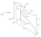
- FIG. 1is a schematic partial cut-away view of a portable exhibit display of the present invention
- FIG. 2Ais a top view of a portion of the portable exhibit display
- FIG. 2Bis an exploded perspective view of the portion of the portable exhibit display illustrated in FIG. 2A ;
- FIG. 2Cis a front elevation view of the portion of the portable exhibit display illustrated in FIG. 2A ;
- FIG. 2Dis an exploded side elevational view of FIG. 2B ;
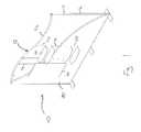
- FIG. 3Ais a top view of an accessory portion of the portable exhibit display
- FIG. 3Bis an exploded perspective view of the accessory illustrated in FIG. 3A ;
- FIG. 3Cis a front elevation view of the accessory illustrated in FIG. 3A ;
- FIG. 3Dis an side elevation view the accessory illustrated in of FIG. 3A .
- a portable exhibit display 10 of the present inventionincludes a frame 12 having a plurality of interconnecting frame members 14 .
- frame members 14include upright members 14 a and cross members 14 b connecting between and/or among upright members 14 a.
- frame members 14are constructed of hollow tubular material.
- the frame membersinclude a tubular side wall 16 and the hollow portion defines a chamber 18 . While a variety of configurations for frame members 14 are contemplated by the present invention, substantially circular or square cross-section hollow tubular frame members 14 are most commonly utilized.
- the portable exhibit display 10 illustrated in FIG. 1includes a fabric covering 30 that is shown partially cut away to reveal frame 12 .
- Fabric covering 30may include a perimeter hem and pockets so as to drape over frame 12 in a manner that the frame members or framework 14 supports the fabric from within a pocket formed by the fabric.
- Alternative arrangementsare also known in the art for securing a covering fabric to a display frame, including hook and loop-type fastening mechanisms, zippers, tie strings, and the like.
- Fabric covering 30may preferably be tensioned to frame 12 to create a smooth display surface appearance.
- Fabric covering 30may be provided in one or more pieces or units for securement to frame 12 as desired.
- the fabric covering 30may be formed from one or more of a variety of materials suitable for the intended use.
- Suitable fabricsinclude woven, non-woven, and laminated constructions of natural or artificial materials, as well as combinations thereof.
- a particular exampleis a polymer-based material suitable as a substrate for graphical printing processes. Examples of such polymer substrate materials include heavy-knit cloths suitable for dye sublimation and direct-type printing processes.
- Fabric covering 30may further exhibit a suitable degree of flexibility for the intended portable exhibit display.
- frame 12may be covered for aesthetic purposes with distinct panels that may or may not include a fabric covering 30 .
- Such display panelsare well known in the art, and may be affixed to frame 12 through known securement means.
- Frame members 14 of frame 12may typically be fabricated from a lightweight metal such as aluminum or titanium, but may be otherwise manufactured from any suitable material or combination of materials, including a fiberglass composite.
- Frame members 14preferably include an array of receptacles 20 in the sidewalls.
- the receptacles 20are formed in the frame members 14 and may extend into the hollow chambers 18 .
- receptacles 20may be openings that are sized to receive and frictionally engage a fitting 22 (see for example FIG. 2B ). Accordingly, the opening of the receptacle 20 may have a diameter that is substantially equivalent to an outer diameter or exterior size of fitting 22 .
- the fitting 22is capable of being inserted into receptacle 20 in a manner, such as a press fit, so that an opening wall 21 defining receptacle 20 frictionally engages outer surface 24 of fitting 22 to securely retain fitting 22 .
- opening wall 21may be enlarged so that the fitting 22 is not frictionally retained within the receptacle 20 .
- an adhesive, screws, magnetic attraction or other known attachment mechanismis utilized to provide a source of retention force for retaining fitting 22 at receptacle 20 .
- magnetic fitting 22includes first and second ends 26 , 28 along a fitting axis 32 , and a cavity 34 that opens to at least first end 26 .
- fitting 22When installed at receptacle 20 , fitting 22 may be substantially contained in chamber 18 .
- Fitting 22may be fabricated from any suitable material, and is configured for installation into receptacle 20 of frame member 14 .
- fitting 22may be fabricated from a polymeric material, such as polyoxymethylene (POM) available from DuPont under the DELRIN® trade name.
- POMpolyoxymethylene
- An example set of dimensional parameters for the present inventionincludes frame members 14 having a substantially circular cross-section with an outer diameter X 1 of about 1.5 in.
- Outer diameter X 2 of a substantially circular cross-section fitting 22may be about 1.25 in., and substantially equivalent to the opening diameter of receptacle 20 .
- first end wall 27may have a width of 0.125 in., such that diameter X 3 of cavity 34 may be about 1 in.
- a depth dimension of cavity 34is preferably appropriate to receive a first magnet 40 therein, and may be, for example, at least 0.5 in.
- Other dimensional arrangements for the components of the present inventionare contemplated as being within the grasp of those having ordinary skill in the art.
- First magnets 40may be secured in respective cavities 34 of fittings 22 positioned at frame members 14 of frame 12 . First magnets 40 may be received in respective cavities 34 so as to be substantially coextensive with first end wall 27 .
- the plurality of first magnets 40define magnetic attachment regions 42 of a magnetic attachment array about frame 12 .
- First magnets 40may be rare earth magnets configured for retention in respective cavities 34 of fittings 22 .
- Example first magnets 40are available from Applied Magnets under the trade name Neodymium magnets.
- first magnet 40may be secured in respective cavities 34 by an attachment, such as adhesives, fasteners, or the like.
- fitting 22may be secured in chamber 18 with a screw 50 that extends through an aperture 21 in frame member 14 , so as to threadably engage with fitting 22 .
- the first magnet 40may be sized and shaped to fit and engage directly into the receptacle 20 and in affect become the magnetic fitting 22 .
- Other mechanisms for additionally or solely securing fitting 22 to frame member 14are known in the art.
- the magnetic attachment array of portable exhibit display 10is useful for the removable securement of one or more accessories 60 .
- an example accessory 60includes a rear surface 62 with one or more attachment points 64 .
- accessory 60may include one or more attachment points 64 in the form of a metallic plate and/or a second magnet 66 adapted to be attracted to first magnets 40 or magnetic fittings 22 of the magnetic attachment array. Accordingly, a polarity of second magnet 66 attracts first magnets 40 , and vice versa, so that accessory 60 may be removably magnetically securable to portable exhibit display 10 .
- second magnets 66are rare earth magnets available from Applied Magnets under the trade name Neodymium magnets. Attachment points 64 , including second magnets 66 , may be secured to accessory 60 in any conventional fashion so that the magnetic attraction between attachment point 64 and first magnets 40 retain accessory 60 at the portable exhibit display 10 .
- accessories 60may be removably magnetically securable to the display frame with the fabric covering 30 in proximity or sandwiched between the framework and the accessory.
- the first or second magnets 40 , 66have sufficient magnetization to retain the accessory against the framework with the fabric covering 30 operably disposed between the first and second magnets 40 , 66 and/or between first magnet 40 and attachment point 64 of accessory 60 .
- Such an arrangementpermits the magnetic securement of accessory 60 with portable exhibit display 10 at fabric covering 30 , and particularly in proximity to respective magnetic attachment regions 42 .
- the magnetic securement capabilityfacilitates rapid and simple attachment and detachment of various accessories.
- the attractive force of at least first magnets 40 to respective attachment points 64provide a “self-locating” function, in which accessory 60 is drawn by magnetic force to an appropriate mounting position wherein the respective attachment points 64 are in proximity to magnetic attachment regions 42 on frame 12 .
- a self-locating functionoperates to correctly position and horizontally level the accessories 60 .
- the magnetic attachment regions 42are provided in predetermined locations of frame 12 at specific spacings and locations to direct a desired magnetic securement of accessories 60 .
- a variety of accessoriesmay be utilized in the portable exhibit display of the present invention. Examples include shelves, graphical apparatus, pegboards, and the like. Applicant further contemplates that side walls (not shown) may be magnetically secured to frame 12 as an accessory 60 , with or without the covering 30 sandwiched between the accessory and framework.
- a flange or end portion of a side wallmay be provided with one or more attachment points 64 for magnetic interaction with magnetic attachment regions 42 of end upright members 14 a of frame 12 . In such a manner, multiple walls may be added as desired without the need for separate mechanical fasteners or apparatus.
Landscapes
- Engineering & Computer Science (AREA)
- Architecture (AREA)
- Civil Engineering (AREA)
- Structural Engineering (AREA)
- Mirrors, Picture Frames, Photograph Stands, And Related Fastening Devices (AREA)
Abstract
Description
Claims (11)
Priority Applications (2)
| Application Number | Priority Date | Filing Date | Title |
|---|---|---|---|
| US14/656,960US9339129B1 (en) | 2014-03-14 | 2015-03-13 | Portable exhibit display with magnetic accessory mounts |
| US15/151,560US9728110B2 (en) | 2014-03-14 | 2016-05-11 | Portable exhibit display with magnetic accessory mounts |
Applications Claiming Priority (2)
| Application Number | Priority Date | Filing Date | Title |
|---|---|---|---|
| US201461953254P | 2014-03-14 | 2014-03-14 | |
| US14/656,960US9339129B1 (en) | 2014-03-14 | 2015-03-13 | Portable exhibit display with magnetic accessory mounts |
Related Child Applications (2)
| Application Number | Title | Priority Date | Filing Date |
|---|---|---|---|
| US15/151,560ContinuationUS9728110B2 (en) | 2014-03-14 | 2016-05-11 | Portable exhibit display with magnetic accessory mounts |
| US15/151,560Continuation-In-PartUS9728110B2 (en) | 2014-03-14 | 2016-05-11 | Portable exhibit display with magnetic accessory mounts |
Publications (1)
| Publication Number | Publication Date |
|---|---|
| US9339129B1true US9339129B1 (en) | 2016-05-17 |
Family
ID=55919955
Family Applications (1)
| Application Number | Title | Priority Date | Filing Date |
|---|---|---|---|
| US14/656,960ActiveUS9339129B1 (en) | 2014-03-14 | 2015-03-13 | Portable exhibit display with magnetic accessory mounts |
Country Status (1)
| Country | Link |
|---|---|
| US (1) | US9339129B1 (en) |
Cited By (3)
| Publication number | Priority date | Publication date | Assignee | Title |
|---|---|---|---|---|
| CN108784052A (en)* | 2018-07-02 | 2018-11-13 | 黑龙江建筑职业技术学院 | Agro based economic development trend distribution deployment map device and application method |
| US10217388B1 (en) | 2017-10-10 | 2019-02-26 | Nimlok Chicago | Display System |
| USD1068348S1 (en)* | 2021-03-23 | 2025-04-01 | Guangzhou Shiyuan Electronic Technology Company Limited | Exhibition stand |
Citations (26)
| Publication number | Priority date | Publication date | Assignee | Title |
|---|---|---|---|---|
| US3017036A (en)* | 1958-12-10 | 1962-01-16 | Pauline M Albert | Magnetic support |
| US4058357A (en)* | 1976-03-31 | 1977-11-15 | Wallace Dewey K | Magnetic radio mounting bracket |
| US4586616A (en)* | 1983-12-09 | 1986-05-06 | R. E. Phelon Company Incorporated | Universal magnetic utensil mounting bar |
| US4658560A (en)* | 1985-10-28 | 1987-04-21 | Beaulieu Bryan J | Support and attachment brace |
| US5417397A (en)* | 1993-12-23 | 1995-05-23 | Harnett; Charles B. | Magnetic soap holder |
| US5746329A (en)* | 1995-08-28 | 1998-05-05 | Northrop Grumman Corporation | Hanger system |
| US6085916A (en)* | 1998-03-27 | 2000-07-11 | Seven Continents Enterprises Incorporated | Demountable hanger bar |
| US6658697B2 (en)* | 2002-02-06 | 2003-12-09 | Shou Hsing Liao | Magnetic glass door holder |
| US6712229B2 (en) | 2001-09-13 | 2004-03-30 | Skyline Displays, Inc. | Display with appurtenance attachment system |
| US20050236347A1 (en) | 2004-04-21 | 2005-10-27 | Acco Brands, Inc. | Display system |
| US7024834B2 (en) | 2002-06-21 | 2006-04-11 | Skyline Displays, Inc. | Framework connection system |
| US7744328B2 (en) | 2005-01-05 | 2010-06-29 | Samsung Mobile Display Co., Ltd. | Apparatus for aligning a tray and tray holder |
| US20100236116A1 (en)* | 2009-03-20 | 2010-09-23 | Skyline Displays, Inc. | Configurable large-depth panel display |
| US8056572B2 (en)* | 2001-06-04 | 2011-11-15 | Evrio, Inc. | System for rapid concealment and shelter including angular frames and warfighter covers |
| US8065847B2 (en) | 2007-01-03 | 2011-11-29 | Skyline Displays, Inc. | Multi-configurable tubular display system |
| US20120044031A1 (en) | 2010-08-20 | 2012-02-23 | Seberu Pico Co., Ltd. | Magnetic Connector |
| US20120119629A1 (en) | 2010-11-12 | 2012-05-17 | Sac Acquisition Llc | Modular furniture assembly and display kit with magnetic coupling assembly |
| US8205846B2 (en)* | 2007-03-02 | 2012-06-26 | Hansgrohe Ag | Magnetic holding device for a shower device on a rod |
| US8312653B2 (en) | 2008-12-01 | 2012-11-20 | Skyline Displays, Inc. | Collapsible tradeshow display with curved panel |
| US8458937B2 (en) | 2004-12-01 | 2013-06-11 | Skyline Displays, Inc. | Tradeshow display formed of banner stands |
| US20130329287A1 (en) | 2011-02-25 | 2013-12-12 | Expand International Ab | Collapsible display means |
| US8750079B2 (en) | 2011-12-07 | 2014-06-10 | Eta Sa Manufacture Horlogere Suisse | Display device with a combination of display members |
| US8807193B2 (en) | 2011-02-25 | 2014-08-19 | Expand International Ab | Collapsible, flexible display system |
| US8879149B2 (en) | 2010-09-17 | 2014-11-04 | Johnson Controls Gmbh | Arrangement for mounting carriers for projection screens of head-up-displays |
| US20150014260A1 (en) | 2013-07-12 | 2015-01-15 | Anthony James Lynch | Sample display holder |
| US8943723B2 (en) | 2013-01-18 | 2015-02-03 | T3 Expo, LLC | Displays with magnetic couplings |
- 2015
- 2015-03-13USUS14/656,960patent/US9339129B1/enactiveActive
Patent Citations (26)
| Publication number | Priority date | Publication date | Assignee | Title |
|---|---|---|---|---|
| US3017036A (en)* | 1958-12-10 | 1962-01-16 | Pauline M Albert | Magnetic support |
| US4058357A (en)* | 1976-03-31 | 1977-11-15 | Wallace Dewey K | Magnetic radio mounting bracket |
| US4586616A (en)* | 1983-12-09 | 1986-05-06 | R. E. Phelon Company Incorporated | Universal magnetic utensil mounting bar |
| US4658560A (en)* | 1985-10-28 | 1987-04-21 | Beaulieu Bryan J | Support and attachment brace |
| US5417397A (en)* | 1993-12-23 | 1995-05-23 | Harnett; Charles B. | Magnetic soap holder |
| US5746329A (en)* | 1995-08-28 | 1998-05-05 | Northrop Grumman Corporation | Hanger system |
| US6085916A (en)* | 1998-03-27 | 2000-07-11 | Seven Continents Enterprises Incorporated | Demountable hanger bar |
| US8056572B2 (en)* | 2001-06-04 | 2011-11-15 | Evrio, Inc. | System for rapid concealment and shelter including angular frames and warfighter covers |
| US6712229B2 (en) | 2001-09-13 | 2004-03-30 | Skyline Displays, Inc. | Display with appurtenance attachment system |
| US6658697B2 (en)* | 2002-02-06 | 2003-12-09 | Shou Hsing Liao | Magnetic glass door holder |
| US7024834B2 (en) | 2002-06-21 | 2006-04-11 | Skyline Displays, Inc. | Framework connection system |
| US20050236347A1 (en) | 2004-04-21 | 2005-10-27 | Acco Brands, Inc. | Display system |
| US8458937B2 (en) | 2004-12-01 | 2013-06-11 | Skyline Displays, Inc. | Tradeshow display formed of banner stands |
| US7744328B2 (en) | 2005-01-05 | 2010-06-29 | Samsung Mobile Display Co., Ltd. | Apparatus for aligning a tray and tray holder |
| US8065847B2 (en) | 2007-01-03 | 2011-11-29 | Skyline Displays, Inc. | Multi-configurable tubular display system |
| US8205846B2 (en)* | 2007-03-02 | 2012-06-26 | Hansgrohe Ag | Magnetic holding device for a shower device on a rod |
| US8312653B2 (en) | 2008-12-01 | 2012-11-20 | Skyline Displays, Inc. | Collapsible tradeshow display with curved panel |
| US20100236116A1 (en)* | 2009-03-20 | 2010-09-23 | Skyline Displays, Inc. | Configurable large-depth panel display |
| US20120044031A1 (en) | 2010-08-20 | 2012-02-23 | Seberu Pico Co., Ltd. | Magnetic Connector |
| US8879149B2 (en) | 2010-09-17 | 2014-11-04 | Johnson Controls Gmbh | Arrangement for mounting carriers for projection screens of head-up-displays |
| US20120119629A1 (en) | 2010-11-12 | 2012-05-17 | Sac Acquisition Llc | Modular furniture assembly and display kit with magnetic coupling assembly |
| US20130329287A1 (en) | 2011-02-25 | 2013-12-12 | Expand International Ab | Collapsible display means |
| US8807193B2 (en) | 2011-02-25 | 2014-08-19 | Expand International Ab | Collapsible, flexible display system |
| US8750079B2 (en) | 2011-12-07 | 2014-06-10 | Eta Sa Manufacture Horlogere Suisse | Display device with a combination of display members |
| US8943723B2 (en) | 2013-01-18 | 2015-02-03 | T3 Expo, LLC | Displays with magnetic couplings |
| US20150014260A1 (en) | 2013-07-12 | 2015-01-15 | Anthony James Lynch | Sample display holder |
Cited By (3)
| Publication number | Priority date | Publication date | Assignee | Title |
|---|---|---|---|---|
| US10217388B1 (en) | 2017-10-10 | 2019-02-26 | Nimlok Chicago | Display System |
| CN108784052A (en)* | 2018-07-02 | 2018-11-13 | 黑龙江建筑职业技术学院 | Agro based economic development trend distribution deployment map device and application method |
| USD1068348S1 (en)* | 2021-03-23 | 2025-04-01 | Guangzhou Shiyuan Electronic Technology Company Limited | Exhibition stand |
Similar Documents
| Publication | Publication Date | Title |
|---|---|---|
| US9728110B2 (en) | Portable exhibit display with magnetic accessory mounts | |
| US8484873B2 (en) | Front-loading display system | |
| US8042308B2 (en) | Wall panel system | |
| US7802390B2 (en) | Configurable modular picture frame | |
| US6889458B2 (en) | Flexible artwork display system | |
| US20130160338A1 (en) | Picture mount apparatus | |
| US8595968B2 (en) | Systems and methods for providing an accessorizable frame system | |
| US9339129B1 (en) | Portable exhibit display with magnetic accessory mounts | |
| US20090193692A1 (en) | Frame for Displaying Holiday or Seasonal Decorations | |
| US11767868B2 (en) | Magnetic bracket assembly for modular furniture system | |
| US8403021B1 (en) | Portable partition system having modular frames, bars, and friction fit spacers | |
| US20180368590A1 (en) | Modular Picture Frame System | |
| GB2466323A (en) | Picture / photo frame with magnetic attachment means | |
| CA2966878C (en) | Portable exhibit display with magnetic accessory mounts | |
| US20080256836A1 (en) | Slip Over Decorative Frame | |
| US8065828B2 (en) | Sheet material display apparatuses | |
| JP3229739U (en) | Background device for shooting | |
| US20210221564A1 (en) | Modular container | |
| EP2663972B1 (en) | Expanding devices | |
| US20090139441A1 (en) | Wrap around banner | |
| US20200273386A1 (en) | Temporary Outdoor Banner and Sign Display Device | |
| JP3226253U (en) | Partition panel | |
| CN223111371U (en) | Screen cloth supporter | |
| US10791855B1 (en) | Frame with ferromagnetic transverse members | |
| US20160296042A1 (en) | Display System |
Legal Events
| Date | Code | Title | Description |
|---|---|---|---|
| AS | Assignment | Owner name:VOMELA SPECIALTY COMPANY, MINNESOTA Free format text:ASSIGNMENT OF ASSIGNORS INTEREST;ASSIGNOR:TAYLOR, KELLY;REEL/FRAME:035160/0987 Effective date:20150311 | |
| STCF | Information on status: patent grant | Free format text:PATENTED CASE | |
| MAFP | Maintenance fee payment | Free format text:PAYMENT OF MAINTENANCE FEE, 4TH YR, SMALL ENTITY (ORIGINAL EVENT CODE: M2551); ENTITY STATUS OF PATENT OWNER: SMALL ENTITY Year of fee payment:4 | |
| FEPP | Fee payment procedure | Free format text:ENTITY STATUS SET TO UNDISCOUNTED (ORIGINAL EVENT CODE: BIG.); ENTITY STATUS OF PATENT OWNER: LARGE ENTITY | |
| MAFP | Maintenance fee payment | Free format text:PAYMENT OF MAINTENANCE FEE, 8TH YEAR, LARGE ENTITY (ORIGINAL EVENT CODE: M1552); ENTITY STATUS OF PATENT OWNER: LARGE ENTITY Year of fee payment:8 | |
| AS | Assignment | Owner name:FORTRESS CREDIT CORP., AS COLLATERAL AGENT, NEW YORK Free format text:SECURITY INTEREST;ASSIGNOR:VOMELA SPECIALTY COMPANY, LLC;REEL/FRAME:069709/0373 Effective date:20241231 |