US9336637B2 - Wireless access control system and related methods - Google Patents
Wireless access control system and related methodsDownload PDFInfo
- Publication number
- US9336637B2 US9336637B2US13/415,365US201213415365AUS9336637B2US 9336637 B2US9336637 B2US 9336637B2US 201213415365 AUS201213415365 AUS 201213415365AUS 9336637 B2US9336637 B2US 9336637B2
- Authority
- US
- United States
- Prior art keywords
- lock
- remote access
- access device
- plugin
- controller
- Prior art date
- Legal status (The legal status is an assumption and is not a legal conclusion. Google has not performed a legal analysis and makes no representation as to the accuracy of the status listed.)
- Active - Reinstated, expires
Links
Images


Classifications
- G—PHYSICS
- G07—CHECKING-DEVICES
- G07C—TIME OR ATTENDANCE REGISTERS; REGISTERING OR INDICATING THE WORKING OF MACHINES; GENERATING RANDOM NUMBERS; VOTING OR LOTTERY APPARATUS; ARRANGEMENTS, SYSTEMS OR APPARATUS FOR CHECKING NOT PROVIDED FOR ELSEWHERE
- G07C9/00—Individual registration on entry or exit
- G07C9/00174—Electronically operated locks; Circuits therefor; Nonmechanical keys therefor, e.g. passive or active electrical keys or other data carriers without mechanical keys
- G07C9/00571—Electronically operated locks; Circuits therefor; Nonmechanical keys therefor, e.g. passive or active electrical keys or other data carriers without mechanical keys operated by interacting with a central unit
- G—PHYSICS
- G07—CHECKING-DEVICES
- G07C—TIME OR ATTENDANCE REGISTERS; REGISTERING OR INDICATING THE WORKING OF MACHINES; GENERATING RANDOM NUMBERS; VOTING OR LOTTERY APPARATUS; ARRANGEMENTS, SYSTEMS OR APPARATUS FOR CHECKING NOT PROVIDED FOR ELSEWHERE
- G07C9/00—Individual registration on entry or exit
- G07C9/00174—Electronically operated locks; Circuits therefor; Nonmechanical keys therefor, e.g. passive or active electrical keys or other data carriers without mechanical keys
- G07C2009/00753—Electronically operated locks; Circuits therefor; Nonmechanical keys therefor, e.g. passive or active electrical keys or other data carriers without mechanical keys operated by active electrical keys
- G07C2009/00769—Electronically operated locks; Circuits therefor; Nonmechanical keys therefor, e.g. passive or active electrical keys or other data carriers without mechanical keys operated by active electrical keys with data transmission performed by wireless means
- G07C2009/00793—Electronically operated locks; Circuits therefor; Nonmechanical keys therefor, e.g. passive or active electrical keys or other data carriers without mechanical keys operated by active electrical keys with data transmission performed by wireless means by Hertzian waves
- G—PHYSICS
- G07—CHECKING-DEVICES
- G07C—TIME OR ATTENDANCE REGISTERS; REGISTERING OR INDICATING THE WORKING OF MACHINES; GENERATING RANDOM NUMBERS; VOTING OR LOTTERY APPARATUS; ARRANGEMENTS, SYSTEMS OR APPARATUS FOR CHECKING NOT PROVIDED FOR ELSEWHERE
- G07C2209/00—Indexing scheme relating to groups G07C9/00 - G07C9/38
- G07C2209/04—Access control involving a hierarchy in access rights
- Y—GENERAL TAGGING OF NEW TECHNOLOGICAL DEVELOPMENTS; GENERAL TAGGING OF CROSS-SECTIONAL TECHNOLOGIES SPANNING OVER SEVERAL SECTIONS OF THE IPC; TECHNICAL SUBJECTS COVERED BY FORMER USPC CROSS-REFERENCE ART COLLECTIONS [XRACs] AND DIGESTS
- Y10—TECHNICAL SUBJECTS COVERED BY FORMER USPC
- Y10T—TECHNICAL SUBJECTS COVERED BY FORMER US CLASSIFICATION
- Y10T70/00—Locks
- Y10T70/50—Special application
- Y10T70/5093—For closures
- Y10T70/5155—Door
Definitions
- the present inventiongenerally relates to access control systems, and more particularly, to wireless access control systems.
- a passive keyless entry (PKE) systemoffers an increased level of convenience over a standard lock and key, for example, by providing the ability to access a secure building or device without having to find, insert, and turn a traditional key.
- PKEpassive keyless entry
- a usermay simply approach a locked PKE lock and with little if any pause, the lock grants this user access if they are carrying an authorized token.
- a PKE systemis currently used in an automotive application and may offer increased convenience by identifying drivers and unlocking the car as they approach. Automotive access is traditionally given by inserting a key into the lock or by pushing buttons on a traditional remote keyless entry (RKE) system. In contrast, a PKE system grants access with reduced user interaction through the use of a token carried by the driver.
- RKEremote keyless entry
- the desired basic perceived behavior of the PKE system in a residential applicationmay be as follows: 1) the user approaches and touches the lock; 2) the lock authenticates the user with a minimally perceived delay; 3) the lock unlocks; 4) the lock may not operate if the authorized user is outside a desired range and the lock is touched by another, unauthorized, user; 5) the lock may not operate if the authorized user is on the inside of the house, and the lock is touched on the outside by an unauthorized user; and 6) the battery powered lock needs months worth of battery life to prevent inconvenient and costly battery changes. 7) when an authorized user revokes a key from another user, it may be revoked within a timely manner.
- a wireless access control systemincludes a remote access device for accessing a lock.
- a plugin devicecommunicates with the remote access device.
- the lockcontains a controller for controlling the ability to lock and unlock a door in which the lock is disposed.
- the lockis in communication with the plugin device.
- the plugin devicedetermines a distance between the remote access device and the lock, and causes the lock to communicate with the remote access device when the remote access device is at a distance less than or equal to a predetermined distance from the lock. At a distance less than or equal to the previous predetermined distance, the system enables the lock to be unlocked by the remote access device.
- the plugin devicedetermines whether the remote access device is authorized to unlock the lock.
- the lockalso communicates with the remote access device, and acting in conjunction with the plugin device, determines the distance of the remote access device from the lock.
- the lockmay also experience a sleep mode, the plugin device waking the lock when the plugin device determines that the remote access device is less than or equal to a predetermined distance from the lock.
- FIG. 1is a schematic diagram of a wireless access system according to the present invention
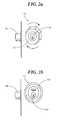
- FIG. 2 ais a perspective view of a lock constructed in accordance with the invention.
- FIG. 2 bis a perspective view of a lock constructed in accordance with another embodiment of the invention.
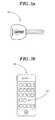
- FIG. 3 ais a top plan view of a remote access device constructed in accordance with the invention as a key;
- FIG. 3 bis a front plan view of a remote access device constructed in accordance with yet another embodiment of the invention as an application for a cell phone;
- FIG. 4is a front plan view of a home-connect plugin of the wireless access system constructed in accordance with the invention.
- FIG. 5is a schematic diagram of the communication between the components of the wireless access system in a typical residential system layout in accordance with the invention
- FIG. 6is a flow chart of operation of the wireless access system in accordance with the invention.
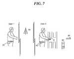
- FIG. 7is a schematic diagram of a system for changing tokens in accordance with the invention.
- a wireless access system 10for example, a PKE system, includes a lock 11 .
- the lock 11may be installed in a standard deadbolt hole and may be battery powered, for example.
- the lock 11may be a human controlled (keyed) lock, for example ( FIG. 2 a ).
- the lock 11includes an outer cylinder 12 that rotates freely around a standard key cylinder 13 . When engaged, the cylinder 13 is linked to a deadbolt 14 , thus giving the user control to extend or retract the deadbolt utilizing their key.
- the lock 11includes a controller 21 or processor and wireless communication circuitry 22 for wireless communication which as will be discussed below, enable remote access device 15 to operate lock 11 .
- the lock 11 ′may be motor powered ( FIG. 2 b ). When a user is in sufficiently close vicinity or touches anywhere on the lock 11 ′, the deadbolt 14 ′ is driven by the motor (not shown) to open the lock for authorized users having the remote access device 15 .
- the lock 11may be another type of lock or locking mechanism and may be installed in any access point, for example.
- the wireless access system 10includes a remote access device 15 .
- the remote access device 15is advantageously a key or token configured to control the lock 11 .
- the remote access device 15may be a standard key including a remote controller 16 for controlling lock 11 and remote wireless access electronics coupled thereto ( FIG. 3 a ).
- Remote access device 15also includes wireless communication circuitry 18 for sending and receiving signals.
- the signalis a Bluetooth signal.
- the remote access device 15may be a mobile wireless communications device, such as, for example, a mobile telephone that may include the remote wireless access electronics described above cooperating with an application 17 ′ stored in memory 17 ( FIG. 3 b ).
- the application 17 ′may be configured to send a signal to provide access and control over the lock 11 ′, for example.
- more than one remote access device 15 ′may be used and may be another type of remote access wireless device, for example, a wireless FOB without the mechanical key, as will be appreciated by those skilled in the art.
- the wireless access system 10also includes a home-connect plugin 30 .
- a typical mains power outlet 31is shown, with the home-connect plugin 30 plugged-into it.
- the home-connect plugin 30includes a home-connect controller 32 and associated wireless communication circuitry 33 cooperating therewith and configured to communicate with the lock 11 , and the remote access device 15 .
- the home-connect plugin 30may also be part of a wireless local area network (WEAN) connectivity, for example, Wi-Fi connectivity, to link it to an off-site web-based server 34 , for example.
- WEANwireless local area network
- the home-connect plugin 30is described herein as a plugin device, it will be appreciated by those skilled in the art that the functionality of the home-connect plugin 30 may be embodied in any of a number of form factors, for example.
- the home connect plugin 30is typically plugged-in to the mains power outlet 31 , at a location in relatively close proximity, sufficient to communicate therewith, to the lock 11 , which may be installed on the front door, for example.
- the remote access device 15approaches from the outside of the home. Both the home-connect plugin 30 and lock 11 are configured to communicate with the remote access device 15 independently or simultaneously, as will be described below and appreciated by those skilled in the art.
- the home-connect plugin 30may be configured to approximately determine the position of the remote access device 15 .
- the home connect plugin 30periodically sends a signal to communicate with a remote access device 15 .
- remote access device 15When remote access device 15 is within range to receive the signal, remote access device 15 outputs a return signal to home-connect plugin 30 .
- Lock 11may also receive, the signal from remote access device 15 .
- RSSIreceived signal strength indication
- lock 11is in a hibernation or low power level state.
- the home-connect plugin 30may send a wakeup signal to the lock 11 .
- home-connect plugin 30may be configured to have an extended range capability, for example, 100 or more meters.
- the lock 11has a smaller range, for example, of about 10 meters, but may be greater in some cases. Therefore, the home-connect plugin 30 may communicate with the remote access device 15 before the lock 11 .
- the home-connect plugin 30may send a signal to the lock 11 to wake up and start communicating with the remote access device 15 to save battery life, for example.
- the battery life of lock 11 and remote access devicecan be extended.
- the home-connect plugin 30may establish a communication link with the remote access device 15 in advance, for example, thus increasing the speed of the authentication process to create little if any perceived delay for the user.
- both the home-connect plugin and the locktrack the RSSI of the remote access device until the algorithm determines it is within a defined accessible range from lock 11 .
- Both the home-connect plugin 30 and the lock 11 gathering RSSI data togethermay utilize this data in an algorithm to determine the position of the remote access device 15 with greater accuracy than either the home-connect plugin 30 or lock 11 alone.
- the home-connect plugin 30grants remote access device 15 access control to the lock 11 . More than one home-connect plugin 30 may be used in some embodiments for more accurate position determining, and to increase authorized user capacity and overall speed of the wireless access system 10 ,
- the lock 11may initially be in a sleep mode to conserve battery power, for example.
- the home-connect plugin 30is typically powered on and searching for authorized remote access devices 15 , i.e. token(s), the standard key, and/or the mobile wireless communications device, in range in a step 100 .
- authorizationis established by syncing the Bluetooth identifier of remote access devices 15 and home-connect plugin 30 as known in the art.
- the home connect plugin 30establishes an asynchronous communication link, (ACL) connection. In this way the system is self authorizing and it only recognizes components with which it has established a connection.
- ACLasynchronous communication link
- the authorized remote access device 15enters the home connected plugin 30 broadcast range in a step 102 .
- the home-connect plugin 30finds an authorized remote access device 15 in range, it establishes connection in a step 104 and begins to monitor the RSSI of the return signal from remote access device 15 to estimate its position.
- a step 106it is determined whether remote access device 15 remains in range of the home connect plugin 30 if not the process returns to step 100 to begin again. If yes, then home connect plugin 30 calculates whether remote access device 15 is approaching and whether it enters the lock wake-up range in step 108 . If not, step 106 is repeated. Once the home-connect plugin 30 estimates that the remote access device 15 has entered the defined wake-up range in a step 108 , it sends a wake-up and connection signal to the lock 11 in a step 110 .
- a step 112it is determined whether lock 11 wakes up and sends confirmation to home connect plugin 30 . If not, the wake-up signal is repeated in step 110 . Once the lock 11 wakes up, it also establishes a low level connection with the remote access device 15 in a step 114 , and begins to monitor the RSSI of the remote access device 15 or devices if there are more than one. Both the home-connect plugin 30 and the lock 11 are monitoring RSSI to more accurately determine the position of the remote access device 15 in a step 118 . This computing may be performed by a processor or controller 32 included within the home-connect plugin 30 , the controller 21 within lock 11 , or both. The home-connect plugin 30 and the lock 11 determine whether the remote access device is within the determined accessible distance in step 116 .
- step 116It is determined whether the home connect plugin 30 and lock 11 calculate the remote access device 15 is within the control range. If not, the determination is again made in step 116 ; if yes, then the user is granted authorization to the lock 11 , and the deadbolt 14 becomes controllable in a step 120 , either extending or retracting per the user's action.
- lock 11goes back to sleep or a low power mode, in a step 122 .
- plugin 30continuously pings lock 10 at a low energy level. If the home-connect plugin 30 loses power or goes offline, the lock 11 may be configured to have a change of status to wake up in the absence of the signals from plugin device 30 , or to be woken up by a user's touch and approximately determine the position of the user by itself, as well as authenticate the user I a manner similar to that described in connection with plug in device 30 .
- home-connect plugin 30may also request the user to verify their access control request by prompting them on their remote access device 15 ′, for example, via a display on their mobile wireless communications device.
- the wireless access system 10may include a calibration feature. More particularly, a connection between the home-connect plugin 30 and the lock 11 may be used by the algorithm to calibrate the RSSI input to adjust for changes in user behavior or environmental conditions, for example.
- plugin device 30determines RSSI values for remote access device 15 over a number of distinct communications. It then determines a maximum average in range value in which communication between plugin device 30 and remote access device 15 occurs and a minimum average in range value at value in which communication between plugin device 30 and remote access device 15 occurs. In this way, the distances at which plugin 30 begins communicating with remote access device 15 self adjusts as a function of user behavioral changes or local conditions.
- the usermay send a termination request to home-connect plugin 30 or to the remote access device key 15 ′ being revoked. If there is no response, the request is broadcast to users, for example, all users, in the “approved” network (i.e. users enrolled in the same lock). The request is stored in the background on their respective keys. Then when any authorized user is in range of the lock 11 , the claimant request is activated and the key code of the requested revoked user is revoked from the lock, denying access to the revoked user.
- the wireless access system 10may also include a computing device 25 , for example, a personal computer at the user's residence for use in the revocation process.
- the computing device 25may include circuitry for wirelessly communicating with the home-connect plugin 30 , remote access device 15 , and/or lock 11 for revoking the permission.
- the computing device 25may include Bluetooth communications circuitry, for example. Other devices and communications protocols may be used in the revocation process.
- wireless access system 10is described herein with respect to a door, the wireless access system may be used for access control or protection of, but not limited to, appliances, a safe, heavy machinery, factory equipment, power tools, pad locks, real estate lock-boxes, garage door openers, etc., for example.
- Alternative remote access device 15 embodimentsmay include a pen, watch, jewelry, headset, FDA, laptop, etc., for example.
- the wireless access system 10may be used to protect other devices or areas where it may be desired to restrict access.
- a first userhas a first remote access device 15 ′ embodied in a mobile communication device that is PKE enabled and is known to plugin device 30 as an authorized user of lock 11 .
- a second userhas a second remote access device embodied in a mobile communication device 15 ′′ that is PKE enabled, but is not authorized for use with lock 11 .
- Both userscan communicate locally with lock 11 via a wireless Bluetooth network as discussed above.
- both usershave the ability to communicate with each other via a cellular network 35 as known in the art, or other wireless communication and as a result have an almost unlimited range.
- the authorized user of lock 11chooses to send an unauthorized user an authorized token for the lock 11 by way of a mobile application 17 on authorized remote access device 15 ′ to unauthorized remote access device 15 ′′.
- the authorized usercan select the option within mobile application 17 on authorized remote access device 15 ′ for a one-time, limited time, or permanent token to send to unauthorized remote access device 15 ′′.
- the key codeis transmitted from the authorize remote access device 15 ′ to the currently unauthorized remote access device 15 ′′ via the cellular network 35 .
- Now unauthorized remote access device 15 ′′becomes an authorized user of the lock 11 .
- authorized remote access device 15 ′sends a request for information to unauthorized remote access device 15 ′′ which responds to authorized remote access device with useful information such as device 15 ′′ Bluetooth address.
- This informationis then transmitted from authorized remote access device 15 ′ to the home connect plugin 30 via the cellular network 35 to the internet, then from the internet to a WiFi router 36 that is in range and can relay the information to the plugin 30 .
- the plugin 30then transfers identification information to the lock 11 , so that when now authorized remote access device 15 ′′ tries to access the lock 11 , it is already a known remote access device.
- the key codecan be sent directly to another device via SMS text message, Email, or other data communication protocols. Additionally, the key codes can be sent to another device through server 34 , or a server disposed in the communications network, which can also act as a master database. Additionally, the key code master database can allow a user to manage (send, receive, revoke) locks from a secured webpage. Additionally, the key code master database can be used to restore a devices key codes via a mobile application with verification upon a lost or damaged device.
- a mobile wireless communications device 15 ′may include the remote access application and a global positioning system (GPS) receiver 23
- GPSglobal positioning system
- the GPS receivermay be used to track the location relative to the lock's position and enable communication by remote access device 15 only when within range. If the remote access device 15 , i.e. mobile wireless communications device 15 ′ is outside the range, as determined by the GPS receiver 23 , it may go into sleep mode or turn off. Additionally, or alternatively, the location of the mobile wireless communication device 15 ′ may be determined via triangulation with wireless service provider base stations or towers, for example.
- the remote access device 15 or mobile wireless communications device 15 ′may wake up, determine a position, calculate a fastest time a user could be within range of the lock 11 , then wake up again at that time and recalculate. When the user is within the range, it may enable the remote access application 17 , and, thus communication for authentication or other purposes.
- the wireless access system 10may be used to augment multi-factor authentication, e.g. use with a biometric identifier, personal identification number (PIN) code, key card, etc.
- the wireless access system 10may also allow simultaneous multiple authentication of remote access device, for example, mobile wireless communications devices. More particularly, the wireless access system 10 may require a threshold number of authorized remote access devices 15 to be present at a same time for authentication to succeed.
- the wireless access system 10advantageously may provide increased security, for example. More particularly, the wireless access system 10 may force the user to authenticate in addition to authorization, via the remote access device 15 before the door can be opened.
- the remote access device 15may include an authentication device 24 for authentication via a biometric, password, PIN, shake pattern, connect-the-dots, or combination thereof, for example, prior to accessing the lock 11 .
- the remote access application 17 on a mobile wireless communications devicefor example, the application may have multiple security levels to enable these features, as will be appreciated by those skilled in the art.
- the wireless access system 10may indicate whether a user locked the door, for example.
- the remote access application 17may log “Lock” with a time stamp so that it may be tracked and checked on the remote access device 15 , i.e. the mobile wireless communications device, for example.
- the wireless access system 10may include a sensing device 26 for example, an accelerometer to track door openings, for example. Based upon the accelerometer, data may be provided through the application or via the Internet or other network, for example.
- the sensing device 26may be another type of device, for example, a touch sensor.
- wireless access system 10may allow authorized visits, for example. More particularly, an authorized visit may be enabled by a 911 dispatcher or other authorized user to allow special or temporary access by the smart phone of a normally unauthorized user, for example.
- the wireless access system 10may keep a log/audit trail. Approval may be granted by trusted a friend or special authority, for example, emergency medical services, a fire department, or a police department.
- the wireless access system 10may also include a security feature whereby when a threshold time has elapsed, the wireless access system may ignore a remote access device 15 in range. This advantageously reduces or may prevent unauthorized access that may occur from leaving a remote access device 15 that is authorized inside near the door.
- a timeout function(via a timer, not shown) may additionally be used in other undesired entry scenarios.
- the wireless access system 10may also log all rejected pairing attempts, as will be appreciated by those skilled in the art.
- the wireless access system 10may also include a revocable key security feature.
- the wireless access system 10may include both revocable and non-revocable keys. If, for example, the wireless access system 10 is unable to access the server 34 to verify keys, for example, the wireless access system may force the application 17 on the remote access device 15 , for example, to check the servers. If the wireless access system 10 is unable to connect or verify the keys, access is denied.
- the revocable key featuremay be particularly advantageous to keep an old boyfriend, for example, who is aware that his key is being revoked from being able to turn off his remote access device 15 so that the key is not deleted.
- a wireless connection for the remote access device 15may be a prerequisite to access in some instances.
- the wireless access system 10has the ability to transfer a key from one remote access device 15 to another with the remote access application 17 , for example. It may be desired that these keys be revocable in some configurations. However, if the remote access device 15 with the key to be revoked is not accessible via the network 27 , then revocation may not be guaranteed if the lock 11 is offline, for example.
- the wireless access system 10advantageously addresses these challenges.
- a proximity detection featuremay be included in the wireless access system 10 , and more particularly, the remote access device 15 may use a magnetic field sensor 39 , such as, for example, a compass in mobile wireless communications device, as a proximity sensor to obtain a more uniform approach/departure distance calibration.
- a magnetic field sensor 39such as, for example, a compass in mobile wireless communications device, as a proximity sensor to obtain a more uniform approach/departure distance calibration.
- a magnetic pulse or pulse sequencemay be used in the lock 11 to illuminate a magnetic flux sensor in the remote access device 15 to establish proximity.
- the remote device 15may be qualified using both radio frequency (RF) and audio, for example.
- the remote access device 15may be a source or sink of audio to help qualify proximity.
- a turn-tab(not shown) may be included that will “flip out” of the front of the lock 11 when pressed to allow the user to turn the lock on an un-powered deadbolt 14 . It may be desirable that the surface area be no larger than a standard key, for example. The user pushes the turn-tab back into the lock face when done.
- the turn-tabmay alternatively be spring loaded, for example.
- the turn-tabmay be added to a powered lock, for example the lock 11 described above. This is may be useful to help force ‘sticky’ locks, for example, as will be appreciated by those skilled in the art. This may also allow the user to give a manual assist to the motor in case of a strike/deadbolt 14 misalignment. This may also allow for operation in a low battery situation, for example. The turn-tab may be particularly useful in other situations.
- one of the deadboltsmay have a traditional key backup as it may be needed for emergencies, for example, while the remaining deadbolts on a house may be keyless. This may eliminate the need to match physical keys on multiple deadbolts, and may reduce the cost for additional deadbolts.
- the wireless access system 10may also include an additional access feature.
- the lock 11could be opened for users who don't have a remote access device 15 . More particularly, they could call a call center or service that could unlock the lock 11 via the Internet 27 , for example, or via other wireless communications protocol. Also, an authorized user could provide this action as well. Additionally, fire/police could gain access by this method if the lock owner opts-in to this service. As will be appreciated by those skilled in the art, alternatively, a command could be sent from the remote access device 15 .
- the wireless access system 10may also include an activation indication.
- the remote access device 15can signal the operator via an auditory tone, vibration or other indication when the lock is activated. This may help communicate actions to the user to reduce any confusion.
- the wireless access system 10may also include an additional security feature.
- the wireless access system 10may use an additional authentication channel, for example, via a WLAN, WiFi, or other communication protocol, either wired or wireless, with the remote access device 15 . This may improve authentication and make spoofing considerably more difficult, as will be appreciated by those skilled in the art.
- the lock 11may include a radar device, or a radar device may be coupled adjacent the lock to detect the locations of the entrant by facing outward in its sweep to resolve inside/outside ambiguity, for example. If the radar does not detect an entrant, then by default the holder of the remote access device is inside and the lock is not activated. The radar may be enabled when the lock 11 is woken up by the home-connect plugin 30 to conserve power.
- the lock 11includes an interior facing directional antenna 50 and a an external facing directional antenna 52 . Each is operatively coupled to wireless communication circuitry 22 to send signals to, and list for signals from, remote access device 15 . If remote access device 15 is interior of the lock, then interior facing directional antenna 50 communicates with remote access device 15 , and the signal strength sensed by directional antenna 50 will be greater than the signal strength sensed by directional antenna 52 (which may be no sensed signal). Lock 11 , and in turn system 10 , determine that remote access device is inside the home, dwelling or structure. Conversely, if remote access device 15 is exterior of the lock, exterior facing directional antenna 52 communicates with remote access device 15 and the signal strength at directional antenna 52 is greater than the signal strength received at directional antenna 50 .
- System 10determines that remote access device 52 is outside of the dwelling and operates as discussed above.
- Home-connect plugin 30compares the signals from interior facing directional antenna 50 and exterior facing directional antenna 52 to confirm the location of remote access device 12 prior to enabling remote access device 15 to control lock 11 . This prevents the door from unlocking each time someone within the structure passes by the lock.
- a mechanical or zero/low-power tilt sensormay be configured to detect break-in events, for example to the lock 11 . eased upon a detected break-in, the lock 11 activate and thereafter communicate to home-connect plugin 30 to report an intruder alert.
- the lock 11may also store information, in a memory, for example, if home-connect plugin is off-line.
- Radar or other motion detector devicemay also be added to the home-connect plugin 30 to assist with inside/outside determination and break-in monitoring.
- the radar or other motion detectormay be used in conjunction with an alarm system, as will be appreciated by those skilled in the art.
- wireless protocolsmay communicate via a wired network and protocols or a combination of wired and wireless networks.
- Bluetooth and WLANi.e. WiFi
- WLANhas been described herein as wireless protocols of particular merit
- other wireless protocolsmay be used, for example, Zywave, ZigBee, near field communication (NFC), and other wireless protocols.
Landscapes
- Physics & Mathematics (AREA)
- General Physics & Mathematics (AREA)
- Lock And Its Accessories (AREA)
Abstract
Description
Claims (29)
Priority Applications (14)
| Application Number | Priority Date | Filing Date | Title |
|---|---|---|---|
| US13/415,365US9336637B2 (en) | 2011-03-17 | 2012-03-08 | Wireless access control system and related methods |
| US13/654,132US9196104B2 (en) | 2011-03-17 | 2012-10-17 | Wireless access control system and related methods |
| US13/734,671US9057210B2 (en) | 2011-03-17 | 2013-01-04 | Wireless access control system and related methods |
| US13/968,067US20140077929A1 (en) | 2012-03-08 | 2013-08-15 | Wireless access control system and related methods |
| US14/304,573US20140292481A1 (en) | 2011-03-17 | 2014-06-13 | Wireless access control system and related methods |
| US14/681,263US9378598B2 (en) | 2011-03-17 | 2015-04-08 | Wireless access control system and related methods |
| US14/681,281US20150213658A1 (en) | 2011-03-17 | 2015-04-08 | Wireless access control system and related methods |
| US14/681,243US9218696B2 (en) | 2011-03-17 | 2015-04-08 | Wireless access control system and related methods |
| US14/882,015US20160035165A1 (en) | 2011-03-17 | 2015-10-13 | Wireless access control system and related methods |
| US14/881,762US20160086400A1 (en) | 2011-03-17 | 2015-10-13 | Wireless access control system including distance based lock assembly and remote access device enrollment and related methods |
| US14/971,308US9501880B2 (en) | 2011-03-17 | 2015-12-16 | Wireless access control system including remote access wireless device generated magnetic field based unlocking and related methods |
| US14/971,264US9501883B2 (en) | 2011-03-17 | 2015-12-16 | Wireless access control system including lock assembly generated magnetic field based unlocking and related methods |
| US15/357,940US9978195B2 (en) | 2011-03-17 | 2016-11-21 | Wireless access control system including remote access wireless device generated magnetic field based unlocking and related methods |
| US15/357,930US9972151B2 (en) | 2011-03-17 | 2016-11-21 | Wireless access control system including lock assembly generated magnetic field based unlocking and related methods |
Applications Claiming Priority (2)
| Application Number | Priority Date | Filing Date | Title |
|---|---|---|---|
| US201161453737P | 2011-03-17 | 2011-03-17 | |
| US13/415,365US9336637B2 (en) | 2011-03-17 | 2012-03-08 | Wireless access control system and related methods |
Related Parent Applications (1)
| Application Number | Title | Priority Date | Filing Date |
|---|---|---|---|
| US13/654,132ContinuationUS9196104B2 (en) | 2011-03-17 | 2012-10-17 | Wireless access control system and related methods |
Related Child Applications (4)
| Application Number | Title | Priority Date | Filing Date |
|---|---|---|---|
| US13/654,132Continuation-In-PartUS9196104B2 (en) | 2011-03-17 | 2012-10-17 | Wireless access control system and related methods |
| US13/734,671Continuation-In-PartUS9057210B2 (en) | 2011-03-17 | 2013-01-04 | Wireless access control system and related methods |
| US14/971,264Continuation-In-PartUS9501883B2 (en) | 2011-03-17 | 2015-12-16 | Wireless access control system including lock assembly generated magnetic field based unlocking and related methods |
| US14/971,308Continuation-In-PartUS9501880B2 (en) | 2011-03-17 | 2015-12-16 | Wireless access control system including remote access wireless device generated magnetic field based unlocking and related methods |
Publications (2)
| Publication Number | Publication Date |
|---|---|
| US20120234058A1 US20120234058A1 (en) | 2012-09-20 |
| US9336637B2true US9336637B2 (en) | 2016-05-10 |
Family
ID=46827360
Family Applications (1)
| Application Number | Title | Priority Date | Filing Date |
|---|---|---|---|
| US13/415,365Active - Reinstated2034-12-15US9336637B2 (en) | 2011-03-17 | 2012-03-08 | Wireless access control system and related methods |
Country Status (1)
| Country | Link |
|---|---|
| US (1) | US9336637B2 (en) |
Cited By (60)
| Publication number | Priority date | Publication date | Assignee | Title |
|---|---|---|---|---|
| US20160275735A1 (en)* | 2013-12-05 | 2016-09-22 | Deutsche Post Ag | Method for causing a change of operating mode |
| US9830760B2 (en)* | 2015-10-10 | 2017-11-28 | Sentrilock, Llc | Contextual data delivery to users at a locked property |
| US20180061156A1 (en)* | 2015-03-23 | 2018-03-01 | Assa Abloy Ab | Considering whether a portable key device is located inside or outside a barrier |
| US10043332B2 (en) | 2016-05-27 | 2018-08-07 | SkyBell Technologies, Inc. | Doorbell package detection systems and methods |
| CN108550217A (en)* | 2018-05-26 | 2018-09-18 | 广东名门锁业有限公司 | A kind of smart lock of recognizable mobile phone and bluetooth key position |
| US10255732B2 (en) | 2016-09-08 | 2019-04-09 | Honeywell International Inc. | Door access control via a mobile device |
| US10318854B2 (en) | 2015-05-13 | 2019-06-11 | Assa Abloy Ab | Systems and methods for protecting sensitive information stored on a mobile device |
| US10380817B2 (en) | 2016-11-28 | 2019-08-13 | Honda Motor Co., Ltd. | System and method for providing hands free operation of at least one vehicle door |
| US10431026B2 (en) | 2015-05-01 | 2019-10-01 | Assa Abloy Ab | Using wearable to determine ingress or egress |
| US10440165B2 (en) | 2013-07-26 | 2019-10-08 | SkyBell Technologies, Inc. | Doorbell communication and electrical systems |
| US10652743B2 (en) | 2017-12-21 | 2020-05-12 | The Chamberlain Group, Inc. | Security system for a moveable barrier operator |
| US10672238B2 (en) | 2015-06-23 | 2020-06-02 | SkyBell Technologies, Inc. | Doorbell communities |
| US10674119B2 (en) | 2015-09-22 | 2020-06-02 | SkyBell Technologies, Inc. | Doorbell communication systems and methods |
| US10706702B2 (en) | 2015-07-30 | 2020-07-07 | Skybell Technologies Ip, Llc | Doorbell package detection systems and methods |
| US10719999B2 (en) | 2017-04-27 | 2020-07-21 | Schlage Lock Company Llc | Technologies for determining intent in an access control system |
| US10793109B2 (en) | 2018-02-01 | 2020-10-06 | Strattec Security Corporation | Methods and systems for providing bluetooth-based passive entry and passive start (PEPS) for a vehicle |
| US10815717B2 (en) | 2016-11-28 | 2020-10-27 | Honda Motor Co., Ltd. | System and method for providing hands free operation of at least one vehicle door |
| US10846964B2 (en) | 2018-06-01 | 2020-11-24 | Sentrilock, Llc | Electronic lockbox with interface to other electronic locks |
| US10862924B2 (en) | 2005-06-30 | 2020-12-08 | The Chamberlain Group, Inc. | Method and apparatus to facilitate message transmission and reception using different transmission characteristics |
| US10876324B2 (en) | 2017-01-19 | 2020-12-29 | Endura Products, Llc | Multipoint lock |
| US10909825B2 (en) | 2017-09-18 | 2021-02-02 | Skybell Technologies Ip, Llc | Outdoor security systems and methods |
| USRE48433E1 (en) | 2005-01-27 | 2021-02-09 | The Chamberlain Group, Inc. | Method and apparatus to facilitate transmission of an encrypted rolling code |
| US10943416B2 (en) | 2018-05-09 | 2021-03-09 | Strattec Security Corporation | Secured communication in passive entry passive start (PEPS) systems |
| US10944559B2 (en) | 2005-01-27 | 2021-03-09 | The Chamberlain Group, Inc. | Transmission of data including conversion of ternary data to binary data |
| US10997810B2 (en) | 2019-05-16 | 2021-05-04 | The Chamberlain Group, Inc. | In-vehicle transmitter training |
| US11004312B2 (en) | 2015-06-23 | 2021-05-11 | Skybell Technologies Ip, Llc | Doorbell communities |
| US11036328B2 (en) | 2019-01-10 | 2021-06-15 | Schlage Lock Company Llc | Touch input lock |
| US11074773B1 (en) | 2018-06-27 | 2021-07-27 | The Chamberlain Group, Inc. | Network-based control of movable barrier operators for autonomous vehicles |
| US11074790B2 (en) | 2019-08-24 | 2021-07-27 | Skybell Technologies Ip, Llc | Doorbell communication systems and methods |
| US11102027B2 (en) | 2013-07-26 | 2021-08-24 | Skybell Technologies Ip, Llc | Doorbell communication systems and methods |
| US11107310B2 (en) | 2019-07-22 | 2021-08-31 | Carrier Corporation | Method and system for access systems |
| US11111698B2 (en) | 2016-12-05 | 2021-09-07 | Endura Products, Llc | Multipoint lock |
| US11140253B2 (en) | 2013-07-26 | 2021-10-05 | Skybell Technologies Ip, Llc | Doorbell communication and electrical systems |
| US11184589B2 (en) | 2014-06-23 | 2021-11-23 | Skybell Technologies Ip, Llc | Doorbell communication systems and methods |
| US11189119B2 (en) | 2019-07-19 | 2021-11-30 | Carrier Corporation | Method and system for access systems |
| US11228739B2 (en) | 2015-03-07 | 2022-01-18 | Skybell Technologies Ip, Llc | Garage door communication systems and methods |
| US11339589B2 (en) | 2018-04-13 | 2022-05-24 | Dormakaba Usa Inc. | Electro-mechanical lock core |
| US11343473B2 (en) | 2014-06-23 | 2022-05-24 | Skybell Technologies Ip, Llc | Doorbell communication systems and methods |
| US11368845B2 (en) | 2017-12-08 | 2022-06-21 | Carrier Corporation | Secure seamless access control |
| US11381686B2 (en) | 2015-04-13 | 2022-07-05 | Skybell Technologies Ip, Llc | Power outlet cameras |
| US11386730B2 (en) | 2013-07-26 | 2022-07-12 | Skybell Technologies Ip, Llc | Smart lock systems and methods |
| US11423717B2 (en) | 2018-08-01 | 2022-08-23 | The Chamberlain Group Llc | Movable barrier operator and transmitter pairing over a network |
| US11434660B2 (en) | 2019-03-27 | 2022-09-06 | Sentri Lock, LLC | Electronic lockbox |
| US11450158B2 (en) | 2018-01-05 | 2022-09-20 | Spectrum Brands, Inc. | Touch isolated electronic lock |
| US11466473B2 (en) | 2018-04-13 | 2022-10-11 | Dormakaba Usa Inc | Electro-mechanical lock core |
| US11575537B2 (en) | 2015-03-27 | 2023-02-07 | Skybell Technologies Ip, Llc | Doorbell communication systems and methods |
| US11651665B2 (en) | 2013-07-26 | 2023-05-16 | Skybell Technologies Ip, Llc | Doorbell communities |
| US11651668B2 (en) | 2017-10-20 | 2023-05-16 | Skybell Technologies Ip, Llc | Doorbell communities |
| US11663864B2 (en) | 2019-11-27 | 2023-05-30 | Schlage Lock Company Llc | Ultra-wideband technologies for seamless access control |
| US11746565B2 (en) | 2019-05-01 | 2023-09-05 | Endura Products, Llc | Multipoint lock assembly for a swinging door panel |
| US11889009B2 (en) | 2013-07-26 | 2024-01-30 | Skybell Technologies Ip, Llc | Doorbell communication and electrical systems |
| US11913254B2 (en) | 2017-09-08 | 2024-02-27 | dormakaba USA, Inc. | Electro-mechanical lock core |
| US11933076B2 (en) | 2016-10-19 | 2024-03-19 | Dormakaba Usa Inc. | Electro-mechanical lock core |
| US11961347B2 (en) | 2018-11-28 | 2024-04-16 | Schlage Lock Company Llc | Seamless access control |
| US11961344B2 (en) | 2021-07-09 | 2024-04-16 | Schlage Lock Company Llc | Ultra-wideband accessory devices for radio frequency intent detection in access control systems |
| US11996623B2 (en) | 2021-12-31 | 2024-05-28 | Schlage Lock Company Llc | UWB antenna solutions for increased accuracy for intent detection in access control systems |
| US12149618B2 (en) | 2005-01-27 | 2024-11-19 | The Chamberlain Group Llc | Method and apparatus to facilitate transmission of an encrypted rolling code |
| US20250034910A1 (en)* | 2023-07-24 | 2025-01-30 | Sentrilock, Llc | Lockbox with double bend shackle |
| US12315318B2 (en) | 2022-09-08 | 2025-05-27 | Sentrilock, Llc | Electronic lockbox with sensor and removable magnetic key fob |
| US12416713B2 (en) | 2022-06-27 | 2025-09-16 | Schlage Lock Company Llc | UWB-based side of door detection for intent analysis |
Families Citing this family (67)
| Publication number | Priority date | Publication date | Assignee | Title |
|---|---|---|---|---|
| US11190936B2 (en) | 2007-09-27 | 2021-11-30 | Clevx, Llc | Wireless authentication system |
| US10778417B2 (en)* | 2007-09-27 | 2020-09-15 | Clevx, Llc | Self-encrypting module with embedded wireless user authentication |
| US10181055B2 (en) | 2007-09-27 | 2019-01-15 | Clevx, Llc | Data security system with encryption |
| US20110100762A1 (en)* | 2008-04-28 | 2011-05-05 | Inventio Ag | Method of using an elevator system, elevator system for such a method and method of retrofitting such an elevator system and electronic door trim |
| CN102015505B (en)* | 2008-04-28 | 2013-11-20 | 因温特奥股份公司 | Method of using elevator system, elevator system used in the method and method of retrofitting the elevator system |
| US9501883B2 (en) | 2011-03-17 | 2016-11-22 | Unikey Technologies Inc. | Wireless access control system including lock assembly generated magnetic field based unlocking and related methods |
| US9336637B2 (en) | 2011-03-17 | 2016-05-10 | Unikey Technologies Inc. | Wireless access control system and related methods |
| US9057210B2 (en) | 2011-03-17 | 2015-06-16 | Unikey Technologies, Inc. | Wireless access control system and related methods |
| US9196104B2 (en) | 2011-03-17 | 2015-11-24 | Unikey Technologies Inc. | Wireless access control system and related methods |
| US9501880B2 (en) | 2011-03-17 | 2016-11-22 | Unikey Technologies Inc. | Wireless access control system including remote access wireless device generated magnetic field based unlocking and related methods |
| US9880604B2 (en)* | 2011-04-20 | 2018-01-30 | Microsoft Technology Licensing, Llc | Energy efficient location detection |
| US9449265B1 (en)* | 2011-08-02 | 2016-09-20 | Impinj International Ltd. | RFID tags with port-dependent functionality |
| US9420432B2 (en) | 2011-12-23 | 2016-08-16 | Microsoft Technology Licensing, Llc | Mobile devices control |
| US9325752B2 (en) | 2011-12-23 | 2016-04-26 | Microsoft Technology Licensing, Llc | Private interaction hubs |
| US9363250B2 (en) | 2011-12-23 | 2016-06-07 | Microsoft Technology Licensing, Llc | Hub coordination service |
| US9467834B2 (en) | 2011-12-23 | 2016-10-11 | Microsoft Technology Licensing, Llc | Mobile device emergency service |
| US20130305354A1 (en) | 2011-12-23 | 2013-11-14 | Microsoft Corporation | Restricted execution modes |
| US8874162B2 (en) | 2011-12-23 | 2014-10-28 | Microsoft Corporation | Mobile device safe driving |
| US9443365B2 (en) | 2012-08-16 | 2016-09-13 | Schlage Lock Company Llc | Wireless reader system |
| US9508206B2 (en) | 2012-08-16 | 2016-11-29 | Schlage Lock Company Llc | Usage of GPS on door security |
| US9230076B2 (en) | 2012-08-30 | 2016-01-05 | Microsoft Technology Licensing, Llc | Mobile device child share |
| EP2704104A1 (en)* | 2012-08-31 | 2014-03-05 | Inventio AG | Inputting lock commands |
| US9053587B2 (en)* | 2012-09-27 | 2015-06-09 | Umm Al-Qura University | Remotely actuated door lock |
| WO2014098760A1 (en) | 2012-12-21 | 2014-06-26 | Nida Tech Sweden Ab | Method, node, computer program and power tool device, for enabling locking and unlocking of power tool |
| WO2014107196A1 (en)* | 2013-01-04 | 2014-07-10 | Unikey Technologies, Inc. | Wireless access control system and related methods |
| KR20140097908A (en)* | 2013-01-30 | 2014-08-07 | 전자부품연구원 | Apparatus and Method for Visitor Management |
| CA2900762C (en) | 2013-02-08 | 2019-10-15 | Schlage Lock Company Llc | Control system and method |
| US8943559B2 (en)* | 2013-03-08 | 2015-01-27 | Nvidia Corporation | Access authentication method and system |
| KR102038746B1 (en) | 2013-03-15 | 2019-10-30 | 스펙트럼 브랜즈, 인크. | Wireless lockset with integrated antenna, touch activation, and light communication device |
| WO2014146186A1 (en)* | 2013-03-22 | 2014-09-25 | Keyfree Technologies Inc. | Managing access to a restricted area |
| US9330275B1 (en)* | 2013-03-28 | 2016-05-03 | Amazon Technologies, Inc. | Location based decryption |
| US9820231B2 (en) | 2013-06-14 | 2017-11-14 | Microsoft Technology Licensing, Llc | Coalescing geo-fence events |
| US9998866B2 (en) | 2013-06-14 | 2018-06-12 | Microsoft Technology Licensing, Llc | Detecting geo-fence events using varying confidence levels |
| EP2816532B1 (en)* | 2013-06-20 | 2019-03-20 | Honeywell International Inc. | Systems and methods for enabling access control via mobile devices |
| EP2821972B1 (en) | 2013-07-05 | 2020-04-08 | Assa Abloy Ab | Key device and associated method, computer program and computer program product |
| PL2821970T5 (en) | 2013-07-05 | 2019-12-31 | Assa Abloy Ab | Access control communication device, method, computer program and computer program product |
| KR102087361B1 (en)* | 2013-11-07 | 2020-03-11 | 아사아블로이코리아 주식회사 | Digital door lock and Digital door lock system |
| US9512643B1 (en)* | 2013-11-14 | 2016-12-06 | Josh Keefe | Door unlocking systems and methods |
| SE538146C2 (en)* | 2013-12-06 | 2016-03-15 | Sweden Connectivity Ab | Passive locking system including means for inside and outside detection |
| KR20160101948A (en)* | 2013-12-23 | 2016-08-26 | 아싸 아블로이 인코퍼레이티드 | Method for utilizing a wireless connection to unlock an opening |
| USD755037S1 (en) | 2014-03-10 | 2016-05-03 | Spectrum Brands, Inc. | Deadbolt with circular light |
| US20150294518A1 (en)* | 2014-04-10 | 2015-10-15 | Ford Global Technologies, Llc | Remotely programmed keyless vehicle entry system |
| CN105095941A (en)* | 2014-05-16 | 2015-11-25 | 中京复电(上海)电子标签集成技术有限公司 | RFID label with port-dependent functionality |
| US9852559B2 (en) | 2014-06-02 | 2017-12-26 | Schlage Lock Company Llc | System and method for signifying intent for lock operation |
| US9576412B2 (en)* | 2014-08-20 | 2017-02-21 | Verizon Patent And Licensing Inc. | Network-assisted remote access portal |
| MX383049B (en) | 2014-12-02 | 2025-03-13 | Carrier Corp | REMOTE PROGRAMMING FOR ACCESS CONTROL SYSTEM WITH VIRTUAL CARD DATA. |
| EP3394839B1 (en)* | 2015-12-23 | 2022-09-28 | Inventio Ag | Access system using a replacement/avoidance function |
| WO2017165349A1 (en) | 2016-03-22 | 2017-09-28 | Spectrum Brands, Inc. | Garage door opener with touch sensor authentication |
| WO2017184513A1 (en) | 2016-04-19 | 2017-10-26 | Spectrum Brands, Inc. | Lockset with integrated wireless signals analysis feature and method |
| US10499228B2 (en) | 2016-11-11 | 2019-12-03 | Carnival Corporation | Wireless guest engagement system |
| US10045184B2 (en) | 2016-11-11 | 2018-08-07 | Carnival Corporation | Wireless guest engagement system |
| US11671807B2 (en)* | 2016-11-11 | 2023-06-06 | Carnival Corporation | Wireless device and methods for making and using the same |
| USD811850S1 (en) | 2017-01-03 | 2018-03-06 | Spectrum Brands, Inc. | Deadbolt for a door |
| US10240363B2 (en) | 2017-01-03 | 2019-03-26 | Spectrum Brands, Inc. | Deadbolt lock assembly with visual feedback |
| USD812447S1 (en) | 2017-01-03 | 2018-03-13 | Spectrum Brands, Inc. | Deadbolt for a door |
| USD811851S1 (en) | 2017-01-03 | 2018-03-06 | Spectrum Brands, Inc. | Deadbolt for a door |
| USD927285S1 (en) | 2017-08-02 | 2021-08-10 | Spectrum Brands, Inc. | Deadbolt faceplate with LED strip having animated illumination |
| CA3020322A1 (en) | 2017-12-13 | 2019-06-13 | Matthew Usi | Systems and methods for threshold detection of a wireless device |
| US10453281B1 (en) | 2018-07-02 | 2019-10-22 | Schlage Lock Company Llc | Tri-angled antenna array for secure access control |
| US10846958B2 (en) | 2019-03-22 | 2020-11-24 | Eingot Llc | Virtual intercom system |
| US11900744B2 (en) | 2019-03-22 | 2024-02-13 | Eingot Llc | Virtual intercom system |
| US10685516B1 (en)* | 2019-03-22 | 2020-06-16 | Eingot Llc | Virtual intercom system |
| US10878650B1 (en) | 2019-06-12 | 2020-12-29 | Honeywell International Inc. | Access control system using mobile device |
| CA3159471A1 (en)* | 2019-12-05 | 2021-06-10 | Kenneth D. GOTO | Smart door lock |
| CN112681905A (en)* | 2020-12-24 | 2021-04-20 | 广州保仕盾智能科技有限公司 | Automatic locking system and method of intelligent door lock |
| US11749045B2 (en) | 2021-03-01 | 2023-09-05 | Honeywell International Inc. | Building access using a mobile device |
| CN117238066B (en)* | 2023-11-13 | 2024-01-19 | 深圳市每开创新科技有限公司 | Unlocking method, passive electronic lock, electronic device and storage medium |
Citations (44)
| Publication number | Priority date | Publication date | Assignee | Title |
|---|---|---|---|---|
| JP2000145222A (en) | 1998-11-12 | 2000-05-26 | Mazda Motor Corp | Keyless entry system |
| US6072402A (en) | 1992-01-09 | 2000-06-06 | Slc Technologies, Inc. | Secure entry system with radio communications |
| US6236333B1 (en) | 1998-06-17 | 2001-05-22 | Lear Automotive Dearborn, Inc. | Passive remote keyless entry system |
| US20020013909A1 (en) | 2000-04-29 | 2002-01-31 | Markus Baumeister | Method of dynamic determination of access rights |
| US6611742B1 (en)* | 2002-04-22 | 2003-08-26 | Lucent Technologies Inc. | Automobile security alarm systems |
| US6621420B1 (en)* | 2001-11-29 | 2003-09-16 | Siavash Poursartip | Device and method for integrated wireless transit and emergency vehicle management |
| JP2003262072A (en) | 2002-03-11 | 2003-09-19 | Nabco Ltd | Door apparatus for vehicle |
| KR20030083538A (en) | 2002-05-03 | 2003-10-30 | 오일권 | Central management key |
| US20030222758A1 (en) | 2002-01-24 | 2003-12-04 | Robin Willats | Vehicle access control and start system |
| KR20040093937A (en) | 2003-04-30 | 2004-11-09 | 주식회사 케이. 디. 티 | A digital door lock system and control method |
| US20050010780A1 (en)* | 2003-07-09 | 2005-01-13 | Kane John Richard | Method and apparatus for providing access to personal information |
| KR20050005786A (en) | 2003-06-30 | 2005-01-14 | 소니 가부시끼 가이샤 | Device registration system, device registration server, device registration method, device registration program, storage medium, and terminal device |
| US20060164208A1 (en)* | 2005-01-14 | 2006-07-27 | Secureall Corporation | Universal hands free key and lock system and method |
| US20060247847A1 (en)* | 2005-03-18 | 2006-11-02 | Carter Scott J | Navigation systems and methods for wheeled objects |
| US7173516B2 (en) | 2004-02-06 | 2007-02-06 | Wayne-Dalton Corp. | Operating system for a motorized barrier operator |
| US20080018437A1 (en) | 2006-05-11 | 2008-01-24 | Trimark Corporation | Illuminated vehicle grab handle with keypad for keyless entry |
| US20080117176A1 (en) | 2006-11-20 | 2008-05-22 | Hon Hai Precision Industry Co., Ltd. | Electronic devices having a touch screen and method for starting the electronic devices |
| US20080231433A1 (en) | 2007-03-21 | 2008-09-25 | Denso International America, Inc. | Ambient noise controlled buzzer answerback |
| KR20080086623A (en) | 2007-03-23 | 2008-09-26 | 한국델파이주식회사 | RBE control method of PGP system |
| US20080238610A1 (en) | 2006-09-29 | 2008-10-02 | Einar Rosenberg | Apparatus and method using near field communications |
| US20090002153A1 (en) | 2006-05-11 | 2009-01-01 | Viktors Berstis | Key Fob and System for Indicating the Lock Status of a Door Lock |
| US20090066476A1 (en) | 2007-04-17 | 2009-03-12 | Fonekey, Inc. | Method of self-service access control for frequent guests of a housing facility |
| CN101532353A (en) | 2008-03-11 | 2009-09-16 | 株式会社易保 | Door lock system with touch pad unit and control method thereof |
| KR20100001206U (en) | 2008-07-25 | 2010-02-03 | 주식회사 아이레보 | Door lock system with touch pad |
| US20100052931A1 (en) | 2008-08-26 | 2010-03-04 | Gm Global Technology Operations, Inc. | Gesture control key fob |
| US20100059231A1 (en) | 2008-09-10 | 2010-03-11 | Benson Thomas | Methods and apparatus for supporting tubulars |
| US7701331B2 (en) | 2006-06-12 | 2010-04-20 | Tran Bao Q | Mesh network door lock |
| US20100164683A1 (en) | 2006-09-12 | 2010-07-01 | Tyco Safety Products Canada Ltd. | Method and apparatus for automatically disarming a security system |
| US20100201536A1 (en) | 2009-02-10 | 2010-08-12 | William Benjamin Robertson | System and method for accessing a structure using a mobile device |
| US20100245038A1 (en) | 2009-03-25 | 2010-09-30 | Lear Corporation | Automatic walk-away detection |
| US20100306549A1 (en) | 2008-01-30 | 2010-12-02 | Evva Sicherheitstechnologie Gmbh | Method and device for managing access control |
| US20110092185A1 (en)* | 2009-10-16 | 2011-04-21 | Robert Garskof | Systems and Methods for Providing Location-Based Application Authentication Using a Location Token Service |
| US20110223868A1 (en)* | 2010-03-12 | 2011-09-15 | Denso Corporation | Portable equipment detecting system |
| WO2011159921A1 (en) | 2010-06-16 | 2011-12-22 | Delphian Systems, LLC | Wireless device enabled locking system |
| US20120234058A1 (en) | 2011-03-17 | 2012-09-20 | Unlkey Technologies, Inc. | Wireless access control system and related methods |
| WO2012134263A1 (en) | 2011-03-25 | 2012-10-04 | Wai Ming Ang | Earth anchor |
| US20120258681A1 (en) | 2011-04-07 | 2012-10-11 | Mobile Security Worldwide Ltd. | Method for emergency signaling via mobile telecommunications device |
| US20120280783A1 (en) | 2011-05-02 | 2012-11-08 | Apigy Inc. | Systems and methods for controlling a locking mechanism using a portable electronic device |
| US8373555B1 (en)* | 2009-04-03 | 2013-02-12 | Clifford A. Redden | Garage door remote system with alert feature |
| US20130176107A1 (en) | 2011-03-17 | 2013-07-11 | Unikey Technologies, Inc | Wireless access control system and related methods |
| US20130237193A1 (en) | 2011-03-17 | 2013-09-12 | Unikey Technologies, Inc. | Wireless access control system and related methods |
| US20130241694A1 (en) | 2012-03-16 | 2013-09-19 | Secureall Corporation | Non-contact electronic door locks having specialized radio frequency beam formation |
| US20140077929A1 (en) | 2012-03-08 | 2014-03-20 | Unikey Technologies, Inc. | Wireless access control system and related methods |
| US20140292481A1 (en) | 2011-03-17 | 2014-10-02 | Unikey Technologies, Inc. | Wireless access control system and related methods |
- 2012
- 2012-03-08USUS13/415,365patent/US9336637B2/enactiveActive - Reinstated
Patent Citations (44)
| Publication number | Priority date | Publication date | Assignee | Title |
|---|---|---|---|---|
| US6072402A (en) | 1992-01-09 | 2000-06-06 | Slc Technologies, Inc. | Secure entry system with radio communications |
| US6236333B1 (en) | 1998-06-17 | 2001-05-22 | Lear Automotive Dearborn, Inc. | Passive remote keyless entry system |
| JP2000145222A (en) | 1998-11-12 | 2000-05-26 | Mazda Motor Corp | Keyless entry system |
| US20020013909A1 (en) | 2000-04-29 | 2002-01-31 | Markus Baumeister | Method of dynamic determination of access rights |
| US6621420B1 (en)* | 2001-11-29 | 2003-09-16 | Siavash Poursartip | Device and method for integrated wireless transit and emergency vehicle management |
| US20030222758A1 (en) | 2002-01-24 | 2003-12-04 | Robin Willats | Vehicle access control and start system |
| JP2003262072A (en) | 2002-03-11 | 2003-09-19 | Nabco Ltd | Door apparatus for vehicle |
| US6611742B1 (en)* | 2002-04-22 | 2003-08-26 | Lucent Technologies Inc. | Automobile security alarm systems |
| KR20030083538A (en) | 2002-05-03 | 2003-10-30 | 오일권 | Central management key |
| KR20040093937A (en) | 2003-04-30 | 2004-11-09 | 주식회사 케이. 디. 티 | A digital door lock system and control method |
| KR20050005786A (en) | 2003-06-30 | 2005-01-14 | 소니 가부시끼 가이샤 | Device registration system, device registration server, device registration method, device registration program, storage medium, and terminal device |
| US20050010780A1 (en)* | 2003-07-09 | 2005-01-13 | Kane John Richard | Method and apparatus for providing access to personal information |
| US7173516B2 (en) | 2004-02-06 | 2007-02-06 | Wayne-Dalton Corp. | Operating system for a motorized barrier operator |
| US20060164208A1 (en)* | 2005-01-14 | 2006-07-27 | Secureall Corporation | Universal hands free key and lock system and method |
| US20060247847A1 (en)* | 2005-03-18 | 2006-11-02 | Carter Scott J | Navigation systems and methods for wheeled objects |
| US20080018437A1 (en) | 2006-05-11 | 2008-01-24 | Trimark Corporation | Illuminated vehicle grab handle with keypad for keyless entry |
| US20090002153A1 (en) | 2006-05-11 | 2009-01-01 | Viktors Berstis | Key Fob and System for Indicating the Lock Status of a Door Lock |
| US7701331B2 (en) | 2006-06-12 | 2010-04-20 | Tran Bao Q | Mesh network door lock |
| US20100164683A1 (en) | 2006-09-12 | 2010-07-01 | Tyco Safety Products Canada Ltd. | Method and apparatus for automatically disarming a security system |
| US20080238610A1 (en) | 2006-09-29 | 2008-10-02 | Einar Rosenberg | Apparatus and method using near field communications |
| US20080117176A1 (en) | 2006-11-20 | 2008-05-22 | Hon Hai Precision Industry Co., Ltd. | Electronic devices having a touch screen and method for starting the electronic devices |
| US20080231433A1 (en) | 2007-03-21 | 2008-09-25 | Denso International America, Inc. | Ambient noise controlled buzzer answerback |
| KR20080086623A (en) | 2007-03-23 | 2008-09-26 | 한국델파이주식회사 | RBE control method of PGP system |
| US20090066476A1 (en) | 2007-04-17 | 2009-03-12 | Fonekey, Inc. | Method of self-service access control for frequent guests of a housing facility |
| US20100306549A1 (en) | 2008-01-30 | 2010-12-02 | Evva Sicherheitstechnologie Gmbh | Method and device for managing access control |
| CN101532353A (en) | 2008-03-11 | 2009-09-16 | 株式会社易保 | Door lock system with touch pad unit and control method thereof |
| KR20100001206U (en) | 2008-07-25 | 2010-02-03 | 주식회사 아이레보 | Door lock system with touch pad |
| US20100052931A1 (en) | 2008-08-26 | 2010-03-04 | Gm Global Technology Operations, Inc. | Gesture control key fob |
| US20100059231A1 (en) | 2008-09-10 | 2010-03-11 | Benson Thomas | Methods and apparatus for supporting tubulars |
| US20100201536A1 (en) | 2009-02-10 | 2010-08-12 | William Benjamin Robertson | System and method for accessing a structure using a mobile device |
| US20100245038A1 (en) | 2009-03-25 | 2010-09-30 | Lear Corporation | Automatic walk-away detection |
| US8373555B1 (en)* | 2009-04-03 | 2013-02-12 | Clifford A. Redden | Garage door remote system with alert feature |
| US20110092185A1 (en)* | 2009-10-16 | 2011-04-21 | Robert Garskof | Systems and Methods for Providing Location-Based Application Authentication Using a Location Token Service |
| US20110223868A1 (en)* | 2010-03-12 | 2011-09-15 | Denso Corporation | Portable equipment detecting system |
| WO2011159921A1 (en) | 2010-06-16 | 2011-12-22 | Delphian Systems, LLC | Wireless device enabled locking system |
| US20120234058A1 (en) | 2011-03-17 | 2012-09-20 | Unlkey Technologies, Inc. | Wireless access control system and related methods |
| US20130176107A1 (en) | 2011-03-17 | 2013-07-11 | Unikey Technologies, Inc | Wireless access control system and related methods |
| US20130237193A1 (en) | 2011-03-17 | 2013-09-12 | Unikey Technologies, Inc. | Wireless access control system and related methods |
| US20140292481A1 (en) | 2011-03-17 | 2014-10-02 | Unikey Technologies, Inc. | Wireless access control system and related methods |
| WO2012134263A1 (en) | 2011-03-25 | 2012-10-04 | Wai Ming Ang | Earth anchor |
| US20120258681A1 (en) | 2011-04-07 | 2012-10-11 | Mobile Security Worldwide Ltd. | Method for emergency signaling via mobile telecommunications device |
| US20120280783A1 (en) | 2011-05-02 | 2012-11-08 | Apigy Inc. | Systems and methods for controlling a locking mechanism using a portable electronic device |
| US20140077929A1 (en) | 2012-03-08 | 2014-03-20 | Unikey Technologies, Inc. | Wireless access control system and related methods |
| US20130241694A1 (en) | 2012-03-16 | 2013-09-19 | Secureall Corporation | Non-contact electronic door locks having specialized radio frequency beam formation |
Non-Patent Citations (5)
| Title |
|---|
| Dumas et al., U.S. Appl. No. 14/681,243, filed Apr. 8, 2015. |
| Dumas et al., U.S. Appl. No. 14/681,263, filed Apr. 8, 2015. |
| Dumas et al., U.S. Appl. No. 14/681,281, filed Apr. 8, 2015. |
| International Search Report of corresponding PCT/US2013/059699. |
| Written Opinion and International Search Report of PCT/US2013/059695. |
Cited By (104)
| Publication number | Priority date | Publication date | Assignee | Title |
|---|---|---|---|---|
| US12149618B2 (en) | 2005-01-27 | 2024-11-19 | The Chamberlain Group Llc | Method and apparatus to facilitate transmission of an encrypted rolling code |
| US10944559B2 (en) | 2005-01-27 | 2021-03-09 | The Chamberlain Group, Inc. | Transmission of data including conversion of ternary data to binary data |
| USRE48433E1 (en) | 2005-01-27 | 2021-02-09 | The Chamberlain Group, Inc. | Method and apparatus to facilitate transmission of an encrypted rolling code |
| US11799648B2 (en) | 2005-01-27 | 2023-10-24 | The Chamberlain Group Llc | Method and apparatus to facilitate transmission of an encrypted rolling code |
| US10862924B2 (en) | 2005-06-30 | 2020-12-08 | The Chamberlain Group, Inc. | Method and apparatus to facilitate message transmission and reception using different transmission characteristics |
| US10440165B2 (en) | 2013-07-26 | 2019-10-08 | SkyBell Technologies, Inc. | Doorbell communication and electrical systems |
| US11889009B2 (en) | 2013-07-26 | 2024-01-30 | Skybell Technologies Ip, Llc | Doorbell communication and electrical systems |
| US11140253B2 (en) | 2013-07-26 | 2021-10-05 | Skybell Technologies Ip, Llc | Doorbell communication and electrical systems |
| US11132877B2 (en) | 2013-07-26 | 2021-09-28 | Skybell Technologies Ip, Llc | Doorbell communities |
| US11102027B2 (en) | 2013-07-26 | 2021-08-24 | Skybell Technologies Ip, Llc | Doorbell communication systems and methods |
| US11362853B2 (en) | 2013-07-26 | 2022-06-14 | Skybell Technologies Ip, Llc | Doorbell communication systems and methods |
| US11386730B2 (en) | 2013-07-26 | 2022-07-12 | Skybell Technologies Ip, Llc | Smart lock systems and methods |
| US10440166B2 (en) | 2013-07-26 | 2019-10-08 | SkyBell Technologies, Inc. | Doorbell communication and electrical systems |
| US11651665B2 (en) | 2013-07-26 | 2023-05-16 | Skybell Technologies Ip, Llc | Doorbell communities |
| US10580241B2 (en)* | 2013-12-05 | 2020-03-03 | Deutsche Post Ag | Method for causing a change of operating mode |
| US20160275735A1 (en)* | 2013-12-05 | 2016-09-22 | Deutsche Post Ag | Method for causing a change of operating mode |
| US11343473B2 (en) | 2014-06-23 | 2022-05-24 | Skybell Technologies Ip, Llc | Doorbell communication systems and methods |
| US11184589B2 (en) | 2014-06-23 | 2021-11-23 | Skybell Technologies Ip, Llc | Doorbell communication systems and methods |
| US11228739B2 (en) | 2015-03-07 | 2022-01-18 | Skybell Technologies Ip, Llc | Garage door communication systems and methods |
| US11388373B2 (en) | 2015-03-07 | 2022-07-12 | Skybell Technologies Ip, Llc | Garage door communication systems and methods |
| US10192372B2 (en)* | 2015-03-23 | 2019-01-29 | Assa Abloy Ab | Considering whether a portable key device is located inside or outside a barrier |
| US20180061156A1 (en)* | 2015-03-23 | 2018-03-01 | Assa Abloy Ab | Considering whether a portable key device is located inside or outside a barrier |
| US11575537B2 (en) | 2015-03-27 | 2023-02-07 | Skybell Technologies Ip, Llc | Doorbell communication systems and methods |
| US11381686B2 (en) | 2015-04-13 | 2022-07-05 | Skybell Technologies Ip, Llc | Power outlet cameras |
| US10431026B2 (en) | 2015-05-01 | 2019-10-01 | Assa Abloy Ab | Using wearable to determine ingress or egress |
| US10318854B2 (en) | 2015-05-13 | 2019-06-11 | Assa Abloy Ab | Systems and methods for protecting sensitive information stored on a mobile device |
| US11004312B2 (en) | 2015-06-23 | 2021-05-11 | Skybell Technologies Ip, Llc | Doorbell communities |
| US10672238B2 (en) | 2015-06-23 | 2020-06-02 | SkyBell Technologies, Inc. | Doorbell communities |
| US10706702B2 (en) | 2015-07-30 | 2020-07-07 | Skybell Technologies Ip, Llc | Doorbell package detection systems and methods |
| US10674119B2 (en) | 2015-09-22 | 2020-06-02 | SkyBell Technologies, Inc. | Doorbell communication systems and methods |
| US9830760B2 (en)* | 2015-10-10 | 2017-11-28 | Sentrilock, Llc | Contextual data delivery to users at a locked property |
| US10026250B2 (en) | 2015-10-10 | 2018-07-17 | Sentrilock, Llc | Contextual data delivery to users at a locked property |
| US11361641B2 (en) | 2016-01-27 | 2022-06-14 | Skybell Technologies Ip, Llc | Doorbell package detection systems and methods |
| US10043332B2 (en) | 2016-05-27 | 2018-08-07 | SkyBell Technologies, Inc. | Doorbell package detection systems and methods |
| US11043056B2 (en) | 2016-09-08 | 2021-06-22 | Honeywell International Inc. | Door access control via a mobile device |
| US10255732B2 (en) | 2016-09-08 | 2019-04-09 | Honeywell International Inc. | Door access control via a mobile device |
| US11721149B2 (en) | 2016-09-08 | 2023-08-08 | Honeywell International Inc. | Door access control via a mobile device |
| US11933076B2 (en) | 2016-10-19 | 2024-03-19 | Dormakaba Usa Inc. | Electro-mechanical lock core |
| US11080952B2 (en) | 2016-11-28 | 2021-08-03 | Honda Motor Co., Ltd. | System and method for providing hands free operation of at least one vehicle door |
| US10380817B2 (en) | 2016-11-28 | 2019-08-13 | Honda Motor Co., Ltd. | System and method for providing hands free operation of at least one vehicle door |
| US10510200B2 (en) | 2016-11-28 | 2019-12-17 | Honda Motor Co., Ltd. | System and method for providing hands free operation of at least one vehicle door |
| US10740993B2 (en) | 2016-11-28 | 2020-08-11 | Honda Motor Co., Ltd. | System and method for providing hands free operation of at least one vehicle door |
| US10815717B2 (en) | 2016-11-28 | 2020-10-27 | Honda Motor Co., Ltd. | System and method for providing hands free operation of at least one vehicle door |
| US10515499B2 (en) | 2016-11-28 | 2019-12-24 | Honda Motor Co., Ltd. | System and method for providing hands free operation of at least one vehicle door |
| US11111698B2 (en) | 2016-12-05 | 2021-09-07 | Endura Products, Llc | Multipoint lock |
| US10876324B2 (en) | 2017-01-19 | 2020-12-29 | Endura Products, Llc | Multipoint lock |
| USD1026613S1 (en) | 2017-01-19 | 2024-05-14 | Endura Products, Llc | Locking device |
| US12104409B2 (en) | 2017-01-19 | 2024-10-01 | Endura Products, Llc | Multipoint lock |
| US12146344B2 (en) | 2017-01-19 | 2024-11-19 | Endura Products, Llc | Multipoint lock |
| US10719999B2 (en) | 2017-04-27 | 2020-07-21 | Schlage Lock Company Llc | Technologies for determining intent in an access control system |
| US11151818B2 (en) | 2017-04-27 | 2021-10-19 | Schlage Lock Company Llc | Technologies for determining intent in an access control system |
| US11913254B2 (en) | 2017-09-08 | 2024-02-27 | dormakaba USA, Inc. | Electro-mechanical lock core |
| US10909825B2 (en) | 2017-09-18 | 2021-02-02 | Skybell Technologies Ip, Llc | Outdoor security systems and methods |
| US11810436B2 (en) | 2017-09-18 | 2023-11-07 | Skybell Technologies Ip, Llc | Outdoor security systems and methods |
| US11651668B2 (en) | 2017-10-20 | 2023-05-16 | Skybell Technologies Ip, Llc | Doorbell communities |
| US11368845B2 (en) | 2017-12-08 | 2022-06-21 | Carrier Corporation | Secure seamless access control |
| US11778464B2 (en) | 2017-12-21 | 2023-10-03 | The Chamberlain Group Llc | Security system for a moveable barrier operator |
| US11122430B2 (en) | 2017-12-21 | 2021-09-14 | The Chamberlain Group, Inc. | Security system for a moveable barrier operator |
| US10652743B2 (en) | 2017-12-21 | 2020-05-12 | The Chamberlain Group, Inc. | Security system for a moveable barrier operator |
| US12108248B2 (en) | 2017-12-21 | 2024-10-01 | The Chamberlain Group Llc | Security system for a moveable barrier operator |
| US11450158B2 (en) | 2018-01-05 | 2022-09-20 | Spectrum Brands, Inc. | Touch isolated electronic lock |
| US11214232B2 (en) | 2018-02-01 | 2022-01-04 | Strattec Security Corporation | Methods and systems for providing Bluetooth-based passive entry and passive start (PEPS) for a vehicle |
| US10793109B2 (en) | 2018-02-01 | 2020-10-06 | Strattec Security Corporation | Methods and systems for providing bluetooth-based passive entry and passive start (PEPS) for a vehicle |
| US12031357B2 (en) | 2018-04-13 | 2024-07-09 | Dormakaba Usa Inc. | Electro-mechanical lock core |
| US12071788B2 (en) | 2018-04-13 | 2024-08-27 | Dormakaba Usa Inc. | Electro-mechanical lock core |
| US11466473B2 (en) | 2018-04-13 | 2022-10-11 | Dormakaba Usa Inc | Electro-mechanical lock core |
| US11447980B2 (en) | 2018-04-13 | 2022-09-20 | Dormakaba Usa Inc. | Puller tool |
| US11339589B2 (en) | 2018-04-13 | 2022-05-24 | Dormakaba Usa Inc. | Electro-mechanical lock core |
| US12435546B2 (en) | 2018-04-13 | 2025-10-07 | Dormakaba Usa Inc. | Electro-mechanical lock core |
| US10943416B2 (en) | 2018-05-09 | 2021-03-09 | Strattec Security Corporation | Secured communication in passive entry passive start (PEPS) systems |
| CN108550217A (en)* | 2018-05-26 | 2018-09-18 | 广东名门锁业有限公司 | A kind of smart lock of recognizable mobile phone and bluetooth key position |
| US10846964B2 (en) | 2018-06-01 | 2020-11-24 | Sentrilock, Llc | Electronic lockbox with interface to other electronic locks |
| US11335150B2 (en) | 2018-06-01 | 2022-05-17 | Sentrilock, Llc | Electronic lockbox with interface to other electronic locks |
| US11074773B1 (en) | 2018-06-27 | 2021-07-27 | The Chamberlain Group, Inc. | Network-based control of movable barrier operators for autonomous vehicles |
| US11763616B1 (en) | 2018-06-27 | 2023-09-19 | The Chamberlain Group Llc | Network-based control of movable barrier operators for autonomous vehicles |
| US12056971B1 (en) | 2018-06-27 | 2024-08-06 | The Chamberlain Group Llc. | Network-based control of movable barrier operators for autonomous vehicles |
| US12354422B2 (en) | 2018-08-01 | 2025-07-08 | The Chamberlain Group Llc | Movable barrier operator and transmitter pairing over a network |
| US11423717B2 (en) | 2018-08-01 | 2022-08-23 | The Chamberlain Group Llc | Movable barrier operator and transmitter pairing over a network |
| US11869289B2 (en) | 2018-08-01 | 2024-01-09 | The Chamberlain Group Llc | Movable barrier operator and transmitter pairing over a network |
| US11961347B2 (en) | 2018-11-28 | 2024-04-16 | Schlage Lock Company Llc | Seamless access control |
| US11435847B2 (en) | 2019-01-10 | 2022-09-06 | Schlage Lock Company Llc | Touch input lock |
| US11036328B2 (en) | 2019-01-10 | 2021-06-15 | Schlage Lock Company Llc | Touch input lock |
| US11434660B2 (en) | 2019-03-27 | 2022-09-06 | Sentri Lock, LLC | Electronic lockbox |
| US11802421B2 (en) | 2019-03-27 | 2023-10-31 | Sentrilock, Llc | Latching apparatus for an electronic lockbox |
| US11761237B2 (en) | 2019-03-27 | 2023-09-19 | Sentrilock, Llc | Electronic lockbox |
| US11761236B2 (en) | 2019-03-27 | 2023-09-19 | Sentrilock, Llc | Electronic lockbox |
| US11753849B2 (en) | 2019-03-27 | 2023-09-12 | Sentrilock, Llc | Electronic lockbox |
| US11598120B2 (en) | 2019-03-27 | 2023-03-07 | Sentrilock, Llc | Latching apparatus for an electronic lockbox |
| US11746565B2 (en) | 2019-05-01 | 2023-09-05 | Endura Products, Llc | Multipoint lock assembly for a swinging door panel |
| US12331553B2 (en) | 2019-05-01 | 2025-06-17 | Endura Products, Llc | Multipoint lock assembly for a swinging door panel |
| US10997810B2 (en) | 2019-05-16 | 2021-05-04 | The Chamberlain Group, Inc. | In-vehicle transmitter training |
| US11462067B2 (en) | 2019-05-16 | 2022-10-04 | The Chamberlain Group Llc | In-vehicle transmitter training |
| US11189119B2 (en) | 2019-07-19 | 2021-11-30 | Carrier Corporation | Method and system for access systems |
| US11107310B2 (en) | 2019-07-22 | 2021-08-31 | Carrier Corporation | Method and system for access systems |
| US11854376B2 (en) | 2019-08-24 | 2023-12-26 | Skybell Technologies Ip, Llc | Doorbell communication systems and methods |
| US11074790B2 (en) | 2019-08-24 | 2021-07-27 | Skybell Technologies Ip, Llc | Doorbell communication systems and methods |
| US11663864B2 (en) | 2019-11-27 | 2023-05-30 | Schlage Lock Company Llc | Ultra-wideband technologies for seamless access control |
| US12217560B2 (en) | 2019-11-27 | 2025-02-04 | Schlage Lock Company Llc | Ultra-wideband technologies for seamless access control |
| US11961344B2 (en) | 2021-07-09 | 2024-04-16 | Schlage Lock Company Llc | Ultra-wideband accessory devices for radio frequency intent detection in access control systems |
| US12327919B2 (en) | 2021-12-31 | 2025-06-10 | Schlage Lock Company Llc | UWB antenna solutions for increased accuracy for intent detection in access control systems |
| US11996623B2 (en) | 2021-12-31 | 2024-05-28 | Schlage Lock Company Llc | UWB antenna solutions for increased accuracy for intent detection in access control systems |
| US12416713B2 (en) | 2022-06-27 | 2025-09-16 | Schlage Lock Company Llc | UWB-based side of door detection for intent analysis |
| US12315318B2 (en) | 2022-09-08 | 2025-05-27 | Sentrilock, Llc | Electronic lockbox with sensor and removable magnetic key fob |
| US20250034910A1 (en)* | 2023-07-24 | 2025-01-30 | Sentrilock, Llc | Lockbox with double bend shackle |
Also Published As
| Publication number | Publication date |
|---|---|
| US20120234058A1 (en) | 2012-09-20 |
Similar Documents
| Publication | Publication Date | Title |
|---|---|---|
| US9336637B2 (en) | Wireless access control system and related methods | |
| US9978195B2 (en) | Wireless access control system including remote access wireless device generated magnetic field based unlocking and related methods | |
| US9972151B2 (en) | Wireless access control system including lock assembly generated magnetic field based unlocking and related methods | |
| US9196104B2 (en) | Wireless access control system and related methods | |
| US9378598B2 (en) | Wireless access control system and related methods | |
| US20160086400A1 (en) | Wireless access control system including distance based lock assembly and remote access device enrollment and related methods | |
| US20140077929A1 (en) | Wireless access control system and related methods | |
| US20140292481A1 (en) | Wireless access control system and related methods | |
| EP2941844A1 (en) | Wireless access control system and related methods | |
| WO2015023737A1 (en) | Wireless access control system and related methods | |
| US20250150527A1 (en) | Systems and Methods for Controlling a Locking Mechanism Using a Portable Electronic Device | |
| KR102323169B1 (en) | Method and system for managing a door entry using beacon signal | |
| WO2020193577A1 (en) | Physical access control systems with localization-based intent detection | |
| US20200329037A1 (en) | Security system with a wireless security device |
Legal Events
| Date | Code | Title | Description |
|---|---|---|---|
| AS | Assignment | Owner name:UNIKEY TECHNOLOGIES, INC., FLORIDA Free format text:ASSIGNMENT OF ASSIGNORS INTEREST;ASSIGNOR:DUMAS, PHIL;REEL/FRAME:028091/0468 Effective date:20120409 | |
| AS | Assignment | Owner name:UNIKEY TECHNOLOGIES INC., FLORIDA Free format text:ASSIGNMENT OF ASSIGNORS INTEREST;ASSIGNOR:NEIL, JIM;REEL/FRAME:028595/0265 Effective date:20120404 | |
| ZAAA | Notice of allowance and fees due | Free format text:ORIGINAL CODE: NOA | |
| ZAAB | Notice of allowance mailed | Free format text:ORIGINAL CODE: MN/=. | |
| ZAAA | Notice of allowance and fees due | Free format text:ORIGINAL CODE: NOA | |
| STCF | Information on status: patent grant | Free format text:PATENTED CASE | |
| AS | Assignment | Owner name:WESTERN ALLIANCE BANK, NEVADA Free format text:INTELLECTUAL PROPERTY SECURITY AGREEMENT;ASSIGNOR:UNIKEY TECHNOLOGIES INC.;REEL/FRAME:050872/0727 Effective date:20190731 | |
| FEPP | Fee payment procedure | Free format text:MAINTENANCE FEE REMINDER MAILED (ORIGINAL EVENT CODE: REM.); ENTITY STATUS OF PATENT OWNER: SMALL ENTITY | |
| FEPP | Fee payment procedure | Free format text:SURCHARGE FOR LATE PAYMENT, SMALL ENTITY (ORIGINAL EVENT CODE: M2554); ENTITY STATUS OF PATENT OWNER: SMALL ENTITY | |
| MAFP | Maintenance fee payment | Free format text:PAYMENT OF MAINTENANCE FEE, 4TH YR, SMALL ENTITY (ORIGINAL EVENT CODE: M2551); ENTITY STATUS OF PATENT OWNER: SMALL ENTITY Year of fee payment:4 | |
| FEPP | Fee payment procedure | Free format text:MAINTENANCE FEE REMINDER MAILED (ORIGINAL EVENT CODE: REM.); ENTITY STATUS OF PATENT OWNER: SMALL ENTITY | |
| LAPS | Lapse for failure to pay maintenance fees | Free format text:PATENT EXPIRED FOR FAILURE TO PAY MAINTENANCE FEES (ORIGINAL EVENT CODE: EXP.); ENTITY STATUS OF PATENT OWNER: SMALL ENTITY | |
| STCH | Information on status: patent discontinuation | Free format text:PATENT EXPIRED DUE TO NONPAYMENT OF MAINTENANCE FEES UNDER 37 CFR 1.362 | |
| FEPP | Fee payment procedure | Free format text:SURCHARGE, PETITION TO ACCEPT PYMT AFTER EXP, UNINTENTIONAL. (ORIGINAL EVENT CODE: M2558); ENTITY STATUS OF PATENT OWNER: SMALL ENTITY | |
| MAFP | Maintenance fee payment | Free format text:PAYMENT OF MAINTENANCE FEE, 8TH YR, SMALL ENTITY (ORIGINAL EVENT CODE: M2552); ENTITY STATUS OF PATENT OWNER: SMALL ENTITY Year of fee payment:8 | |
| FEPP | Fee payment procedure | Free format text:PETITION RELATED TO MAINTENANCE FEES FILED (ORIGINAL EVENT CODE: PMFP); ENTITY STATUS OF PATENT OWNER: SMALL ENTITY | |
| FP | Lapsed due to failure to pay maintenance fee | Effective date:20240510 | |
| FEPP | Fee payment procedure | Free format text:PETITION RELATED TO MAINTENANCE FEES DISMISSED (ORIGINAL EVENT CODE: PMFS); ENTITY STATUS OF PATENT OWNER: SMALL ENTITY | |
| FEPP | Fee payment procedure | Free format text:PETITION RELATED TO MAINTENANCE FEES FILED (ORIGINAL EVENT CODE: PMFP); ENTITY STATUS OF PATENT OWNER: SMALL ENTITY | |
| PRDP | Patent reinstated due to the acceptance of a late maintenance fee | Effective date:20241126 | |
| FEPP | Fee payment procedure | Free format text:PETITION RELATED TO MAINTENANCE FEES GRANTED (ORIGINAL EVENT CODE: PMFG); ENTITY STATUS OF PATENT OWNER: SMALL ENTITY | |
| STCF | Information on status: patent grant | Free format text:PATENTED CASE | |
| AS | Assignment | Owner name:UNIKEY TECHNOLOGIES INC., FLORIDA Free format text:RELEASE BY SECURED PARTY;ASSIGNOR:WESTERN ALLIANCE BANK;REEL/FRAME:072069/0963 Effective date:20220627 |