US9335922B2 - Electronic device including three-dimensional gesture detecting display - Google Patents
Electronic device including three-dimensional gesture detecting displayDownload PDFInfo
- Publication number
- US9335922B2 US9335922B2US13/743,264US201313743264AUS9335922B2US 9335922 B2US9335922 B2US 9335922B2US 201313743264 AUS201313743264 AUS 201313743264AUS 9335922 B2US9335922 B2US 9335922B2
- Authority
- US
- United States
- Prior art keywords
- antennae
- display
- gesture
- disposed
- electronic device
- Prior art date
- Legal status (The legal status is an assumption and is not a legal conclusion. Google has not performed a legal analysis and makes no representation as to the accuracy of the status listed.)
- Active, expires
Links
Images


Classifications
- G—PHYSICS
- G06—COMPUTING OR CALCULATING; COUNTING
- G06F—ELECTRIC DIGITAL DATA PROCESSING
- G06F3/00—Input arrangements for transferring data to be processed into a form capable of being handled by the computer; Output arrangements for transferring data from processing unit to output unit, e.g. interface arrangements
- G06F3/01—Input arrangements or combined input and output arrangements for interaction between user and computer
- G06F3/048—Interaction techniques based on graphical user interfaces [GUI]
- G06F3/0487—Interaction techniques based on graphical user interfaces [GUI] using specific features provided by the input device, e.g. functions controlled by the rotation of a mouse with dual sensing arrangements, or of the nature of the input device, e.g. tap gestures based on pressure sensed by a digitiser
- G06F3/0488—Interaction techniques based on graphical user interfaces [GUI] using specific features provided by the input device, e.g. functions controlled by the rotation of a mouse with dual sensing arrangements, or of the nature of the input device, e.g. tap gestures based on pressure sensed by a digitiser using a touch-screen or digitiser, e.g. input of commands through traced gestures
- G06F3/04883—Interaction techniques based on graphical user interfaces [GUI] using specific features provided by the input device, e.g. functions controlled by the rotation of a mouse with dual sensing arrangements, or of the nature of the input device, e.g. tap gestures based on pressure sensed by a digitiser using a touch-screen or digitiser, e.g. input of commands through traced gestures for inputting data by handwriting, e.g. gesture or text
- G—PHYSICS
- G06—COMPUTING OR CALCULATING; COUNTING
- G06F—ELECTRIC DIGITAL DATA PROCESSING
- G06F3/00—Input arrangements for transferring data to be processed into a form capable of being handled by the computer; Output arrangements for transferring data from processing unit to output unit, e.g. interface arrangements
- G06F3/01—Input arrangements or combined input and output arrangements for interaction between user and computer
- G06F3/017—Gesture based interaction, e.g. based on a set of recognized hand gestures
- G—PHYSICS
- G06—COMPUTING OR CALCULATING; COUNTING
- G06F—ELECTRIC DIGITAL DATA PROCESSING
- G06F3/00—Input arrangements for transferring data to be processed into a form capable of being handled by the computer; Output arrangements for transferring data from processing unit to output unit, e.g. interface arrangements
- G06F3/01—Input arrangements or combined input and output arrangements for interaction between user and computer
- G06F3/03—Arrangements for converting the position or the displacement of a member into a coded form
- G06F3/041—Digitisers, e.g. for touch screens or touch pads, characterised by the transducing means
- G06F3/046—Digitisers, e.g. for touch screens or touch pads, characterised by the transducing means by electromagnetic means
- G—PHYSICS
- G06—COMPUTING OR CALCULATING; COUNTING
- G06F—ELECTRIC DIGITAL DATA PROCESSING
- G06F3/00—Input arrangements for transferring data to be processed into a form capable of being handled by the computer; Output arrangements for transferring data from processing unit to output unit, e.g. interface arrangements
- G06F3/01—Input arrangements or combined input and output arrangements for interaction between user and computer
- G06F3/03—Arrangements for converting the position or the displacement of a member into a coded form
- G06F3/041—Digitisers, e.g. for touch screens or touch pads, characterised by the transducing means
- G—PHYSICS
- G06—COMPUTING OR CALCULATING; COUNTING
- G06K—GRAPHICAL DATA READING; PRESENTATION OF DATA; RECORD CARRIERS; HANDLING RECORD CARRIERS
- G06K19/00—Record carriers for use with machines and with at least a part designed to carry digital markings
- G06K19/06—Record carriers for use with machines and with at least a part designed to carry digital markings characterised by the kind of the digital marking, e.g. shape, nature, code
- G06K19/067—Record carriers with conductive marks, printed circuits or semiconductor circuit elements, e.g. credit or identity cards also with resonating or responding marks without active components
- G06K19/07—Record carriers with conductive marks, printed circuits or semiconductor circuit elements, e.g. credit or identity cards also with resonating or responding marks without active components with integrated circuit chips
- G06K19/0723—Record carriers with conductive marks, printed circuits or semiconductor circuit elements, e.g. credit or identity cards also with resonating or responding marks without active components with integrated circuit chips the record carrier comprising an arrangement for non-contact communication, e.g. wireless communication circuits on transponder cards, non-contact smart cards or RFIDs
- G06K9/00201—
- G—PHYSICS
- G06—COMPUTING OR CALCULATING; COUNTING
- G06V—IMAGE OR VIDEO RECOGNITION OR UNDERSTANDING
- G06V20/00—Scenes; Scene-specific elements
- G06V20/60—Type of objects
- G06V20/64—Three-dimensional objects
Definitions
- the present disclosurerelates to electronic devices, including but not limited to, portable electronic devices having three-dimensional gesture detecting displays and their control.
- Portable electronic devicesinclude, for example, several types of mobile stations such as simple cellular telephones, smart phones, wireless personal digital assistants (PDAs), and laptop computers with wireless 802.11 or Bluetooth capabilities.
- PIMpersonal information manager
- a touch-sensitive displayalso known as a touchscreen display, and displays or devices capable of detecting objects spaced from the display are particularly useful on handheld devices, which are small and have limited space for user input and output.
- the information displayed on the touch-sensitive displaysmay be modified depending on the functions and operations being performed.
- FIG. 1is a block diagram of a portable electronic device in accordance with the disclosure.
- FIG. 2is an exploded view of a three-dimensional gesture detecting display of an electronic device in accordance with the disclosure.
- FIG. 3is a simplified perspective view of an electronic device.
- FIG. 4is a perspective view illustrating the electromagnetic field created by antennae of the electronic device of FIG. 3 .
- FIG. 5is a perspective view illustrating the effect of an object in the electromagnetic field of FIG. 4 .
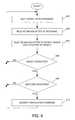
- FIG. 6is a flowchart illustrating a method of detecting attributes, including location of an object in accordance with the disclosures.
- FIG. 7 through FIG. 10illustrate an example of object detection and a resulting change in a displayed object.
- the followingdescribes an electronic device and a three-dimensional gesture detecting display that includes a plurality of antennae arranged and constructed to emit a signal and to receive backscatter from the signal, and a processor operably coupled to the antennae to utilize the received backscatter to detect location and at least one of size and shape of an object spaced from the display.
- the disclosuregenerally relates to an electronic device, such as a portable electronic device or non-portable electronic device.
- portable electronic devicesinclude mobile, or handheld, wireless communication devices such as pagers, cellular phones, cellular smart-phones, wireless organizers, personal digital assistants, wirelessly enabled notebook computers, tablet computers, mobile internet devices, electronic navigation devices, and so forth.
- the portable electronic devicemay be a portable electronic device without wireless communication capabilities, such as handheld electronic games, digital photograph albums, digital cameras, media players, e-book readers, and so forth.
- non-portable electronic devicesinclude desktop computers, electronic white boards, smart boards utilized for collaboration, built-in monitors or displays in furniture or appliances, and so forth.
- FIG. 1A block diagram of an example of a portable electronic device 100 is shown in FIG. 1 .
- the portable electronic device 100includes multiple components, such as a processor 102 that controls the overall operation of the portable electronic device 100 . Communication functions, including data and voice communications, are performed through a communication subsystem 104 . Data received by the portable electronic device 100 is decompressed and decrypted by a decoder 106 .
- the communication subsystem 104receives messages from and sends messages to a wireless network 150 .
- the wireless network 150may be any type of wireless network, including, but not limited to, data wireless networks, voice wireless networks, and networks that support both voice and data communications.
- a power source 142such as one or more rechargeable batteries or a port to an external power supply, powers the portable electronic device 100 .
- the processor 102interacts with other components, such as a Random Access Memory (RAM) 108 , memory 110 , a three-dimensional gesture detecting display 118 , an auxiliary input/output (I/O) subsystem 124 , a data port 126 , a speaker 128 , a microphone 130 , short-range communications 132 and other device subsystems 134 .
- the three-dimensional gesture detecting display 118includes a display 112 and antennae 114 that are coupled to at least one controller 116 that is utilized to interact with the processor 102 .
- the controller 116 and antennae 114are utilized as a transceiver to transmit and receive signals. Input via a graphical user interface is provided via the three-dimensional gesture detecting display 118 .
- Informationsuch as text, characters, symbols, images, icons, and other items that may be displayed or rendered on a portable electronic device, is displayed on the display 112 via the processor 102 .
- the processor 102may also interact with an accelerometer 136 that may be utilized to detect direction of gravitational forces or gravity-induced reaction forces.
- the portable electronic device 100may utilize a Subscriber Identity Module or a Removable User Identity Module (SIM/RUIM) card 138 for communication with a network, such as the wireless network 150 .
- SIM/RUIMRemovable User Identity Module
- user identification informationmay be programmed into memory 110 .
- the portable electronic device 100includes an operating system 146 and software programs, applications, or components 148 that are executed by the processor 102 and are typically stored in a persistent, updatable store such as the memory 110 . Additional applications or programs may be loaded onto the portable electronic device 100 through the wireless network 150 , the auxiliary I/O subsystem 124 , the data port 126 , the short-range communications subsystem 132 , or any other suitable subsystem 134 .
- a received signalsuch as a text message, an e-mail message, or web page download is processed by the communication subsystem 104 and input to the processor 102 .
- the processor 102processes the received signal for output to the display 112 and/or to the auxiliary I/O subsystem 124 .
- a subscribermay generate data items, for example e-mail messages, which may be transmitted over the wireless network 150 through the communication subsystem 104 .
- the speaker 128outputs audible information converted from electrical signals
- the microphone 130converts audible information into electrical signals for processing.
- the three-dimensional gesture detecting display 118includes the antennae 114 .
- the antennae 114may include transmit antennae and receive antennae. Alternatively, the antennae may include antennae that are operable to transmit and to receive signals.
- the antennaemay comprise any suitable material, such as indium tin oxide (ITO).
- ITOindium tin oxide
- the antennaemay be formed, for example, by depositing ITO on one or more layers on the display 112 and patterning to form the antennae.
- One or more objectsmay be detected by the three-dimensional gesture detecting display 118 .
- the processor 102may determine attributes of the object, including a location of the object.
- Location datamay include data for a size of an object, a location of the object or location or a single point on the object, such as a point at or near a center of a detected area.
- the location of a detected objectmay include x, y, and z components, e.g., horizontal and vertical components, with respect to one's view of the display 112 , and distance from the display 112 , respectively.
- the detected objectmay be a finger, thumb, hand, appendage, or other objects, for example, a stylus, pen, or other pointers.
- One or more gesturesmay also be detected by the three-dimensional gesture detecting display 118 .
- a gesturesuch as a movement of an object relative to the three-dimensional gesture detecting display 118 , may be identified by attributes of the gesture, including the origin point, the end point, the distance travelled, the duration, the velocity, and the direction, for example.
- a gesturemay be long or short in distance and/or duration. Two points of a gesture may be utilized to determine a direction of the gesture.
- a gesturemay also include a hover. A hover may occur when an object is at a location that is spaced from the three-dimensional gesture detecting display 118 and that is generally unchanged over a period of time.
- the display 112includes a display area in which information may be displayed, and a non-display area extending around the periphery of the display area.
- the non-display areais utilized to accommodate, for example, electronic traces or electrical connections, adhesives or other sealants, and/or protective coatings around the edges of the display area and information is not displayed in the non-display area.
- the non-display areamay be referred to as an inactive area and is not part of the physical housing or frame of the electronic device.
- no pixels of the displayare in the non-display area, thus no image can be displayed by the display 112 in the non-display area.
- a secondary displaynot part of the primary display 112 , may be disposed under the non-display area.
- Antennae 114may be disposed in the non-display area, which antennae extend from the display area or may be distinct or separate antennae from the antennae in the display area.
- FIG. 2An exploded view of one example of a three-dimensional gesture detecting display 118 of an electronic device 100 is shown in FIG. 2 .
- the three-dimensional gesture detecting display 118includes the display 112 and a substrate 202 disposed on the display 112 .
- the substrate 202may be any suitable dielectric or insulator material such as glass.
- the antennae 114are disposed on the substrate 202 .
- the antennae 114include transmit antennae 204 disposed on one surface 208 of the substrate 202 and receive antennae 206 disposed on an opposite surface 210 of the substrate 202 .
- the transmit antennae 204are disposed on the surface 208 of the substrate 202 that is closest to or on the display 112 such that the receive antennae 206 are disposed on an outer surface of the substrate 202 or the surface 210 that is farthest from the display 112 .
- the transmit antennae 204are disposed on a different layer of the three-dimensional gesture detecting display 118 than the receive antennae 206 .
- the transmit antennae 204are arranged in an array on the surface 208 of the substrate 202 and the receive antennae 206 are arranged in an array on the opposite surface 210 of the substrate 202 to provide co-polarized dipoles. Alternatively, cross-polarized antennae may be successfully implemented. A local measurement of the received signal is taken at the port 212 for each receive antenna 206 when in use.
- the transmit antennae 204 and the receive antennae 206are controlled by the controller 116 .
- the controller 116controls when the antennae are turned on or when they operate.
- the transmit antennae 204transmits a radio signal, in the MHz or GHz range, such as a microwave signal.
- the received signal from the port 212 of the receive antennae 206is an electromagnetic wave that is utilized to determine the electric field and/or the magnetic field.
- the electric field and the magnetic field from each of the receive antennae 206are utilized to detect an object that is spaced from the three-dimensional gesture detecting display 118 .
- the voltage signal from the receive antennae 206may also be utilized to detect an object that is spaced from the three-dimensional gesture detecting display 118 .
- An object that is spaced from the three-dimensional gesture detecting display 118is detected based on changes in the electric field and/or the magnetic field when the object enters the space in front of the three-dimensional gesture detecting display 118 , compared to the electric field and/or the magnetic field measured when no object is present.
- Radar positioning techniquesmay be utilized to determine the location of the object and the time differences between transmitted signals and received signals may be utilized to determine the distance of the object from the three-dimensional gesture detecting display 118 .
- Changes in the electric field or magnetic fieldare determined when the distance between the object and the three-dimensional gesture detecting display 118 changes, i.e., the object moves toward or away from the three-dimensional gesture detecting display 118 .
- the changes in the electric field or magnetic fieldfacilitate detection of distance between the three-dimensional gesture detecting display 118 and the object.
- movement toward or away from the three-dimensional gesture detecting display 118may be detected.
- Changes in the electric field or the magnetic fieldare also determined when the object moves relative to the three-dimensional gesture detecting display 118 , but the distance between the three-dimensional gesture detecting display 118 and the object is generally unchanged, i.e., the object moves generally parallel to the three-dimensional gesture detecting display 118 .
- movement in a plane that is generally parallel to the three-dimensional gesture detecting display 118may also be detected.
- Movement of an object in any directionmay be detected based on calculations utilizing the electric field changes and/or the magnetic field changes.
- the shape of an objectmay also be determined such that a large object is distinguishable from a small object.
- the size and shape of the objectis determined, for example, based on the changes in the electric field compared to the electric field when an object is not present.
- Microwave-based imagingmay be performed.
- shape and/or sizemay be determined, for example, to identify the object.
- Movement of the objectis also detected such that gestures may be identified based on the gesture attributes such as speed, shape, and direction.
- the objectmay be identified.
- the number of gestures that may be determined or distinguishedis greater compared to a device that is incapable of detecting or identifying size or shape of an object because the three-dimensional gesture detecting display 118 may be utilized to detect and distinguish between objects of different sizes and between shapes of objects, such as shapes that a hand may take, including shapes in which a finger or fingers are extended or a “thumbs-up” shape, for example.
- FIG. 3A simplified perspective view of an example of a portable electronic device 100 is illustrated in FIG. 3 , FIG. 4 , and FIG. 5 .
- the portable electronic device 100includes a single transmit antenna 204 and a single receive antenna 206 that are disposed on surfaces of a substrate of the portable electronic device 100 .
- the portable electronic device 100includes a printed circuit board 302 that is utilized to support and couple electronic components of the portable electronic device 100 .
- a power source 142which in this example is a battery, is also illustrated.
- the far field pattern of the electromagnetic field that is created when the transmit antenna 204 of FIG. 3 is excitedis illustrated in FIG. 4 .
- the far field pattern of the electromagnetic fieldis affected by the presence of an object spaced from the three-dimensional gesture detecting display 118 .
- a far field pattern of the electromagnetic field when an object 502 is present in the fieldis illustrated in FIG. 5 .
- the object 502is a rectangular parallelepiped. Objects of other shapes affect the pattern of the electromagnetic field such that the pattern of the electromagnetic field differs when different objects are present in the field, compared to the pattern of the electromagnetic field when no object is present.
- Backscatterrefers to the signal sent from a transmit antennae 204 that is reflected or scattered from an object such as a finger or hand. The backscatter is analyzed to detect the object.
- the received signal from the receive antennae 206is an electromagnetic wave that is utilized to determine the electric field and/or the magnetic field.
- the signal from each receive antennae 206is utilized to detect an object that is spaced from the three-dimensional gesture detecting display 118 .
- the voltage signal from the receive antennae 206may also be utilized to detect an object that is spaced from the three-dimensional gesture detecting display 118 .
- the signals received at the receive antennaeare sampled regularly and analyzed to detect objects spaced from the three-dimensional gesture detecting display 118 .
- the signalsare collected and the corresponding equation, e.g., Maxwell equation at low frequency, is solved iteratively for different gestures to obtain the solution that is closest to the collected values.
- a library or table of predefined gestures or objectsmay be stored on the portable electronic device 100 .
- the expected signals for the predefined gestures or objectsmay be determined utilizing corresponding Maxwell equations.
- the expected signalsmay be determined and stored in the library or table stored on the portable electronic device 100 .
- the expected signals for one of the predefined gesture or objectsare compared to the measured signals from each of the receive antennae 206 to determine whether or not the expected signals for the predefined gesture or object match the measured signals from each of the receive antennae 206 , within an acceptable error threshold. When a match is identified, within the error threshold, the associated predefined gesture or object is identified as the detected gesture or object. When a match is not identified, the expected signals for a next predefined gesture or object are compared the measure signals. Thus, the process continues until an acceptable match is found or until no predefined gesture or object is a sufficient match.
- FIG. 6A flowchart illustrating a method of detecting attributes of an object spaced from the display 112 , such as the three-dimensional gesture detecting display 118 of FIG. 2 , is illustrated in FIG. 6 .
- the methodmay be carried out by software executed, for example, by the controller 116 and the processor 102 . Coding of software for carrying out such a method is within the scope of a person of ordinary skill in the art given the present description.
- the methodmay contain additional or fewer processes than shown and/or described, and may be performed in a different order.
- Computer-readable code executable by at least one processor of the portable electronic device to perform the methodmay be stored in a computer-readable storage medium, such as a computer-readable storage device.
- the transmit antennae 204are controlled by the controller 116 and signals are emitted 602 from the transmit antennae 204 .
- the signalsare high frequency signals in the MHz or GHz range, such as a microwave signal.
- Backscatter from the signalsis received 604 at the receive antennae 206 .
- the backscatteris analyzed 306 to detect location of an object.
- the backscattermay also be analyzed 606 to detect the size and/or shape of the object.
- the attributes of the objectincluding location, size and/or shape, are compared to previous attributes of the object based on previously measured values, to identify 610 a gesture.
- the processcontinues at 602 to continue to monitor the object to identify gestures by repeating signal emission from the transmit antennae 204 , receiving backscatter at the receive antennae 206 and analyzing to detect location and at least one of size and shape of the object.
- valuesare measured dynamically to detect an object and to detect changes in object attributes such as location.
- the gestureis identified by comparing attributes of the gesture to attributes of known gestures or defined gestures.
- the associated commandis identified 612 .
- a gesturemay be associated with a command utilizing a look-up table. Any suitable command may be utilized.
- commandsmay be utilized to open or launch an application, to close an application, to proceed to a next photo or image, to reverse back to a previous image, to scroll, and to zoom, to name a small number of examples.
- FIG. 7 through FIG. 10A side view of one example of a portable electronic device 100 is shown in FIG. 7 and a front view the portable electronic device 100 is shown in FIG. 8 .
- an object 702is present in the electromagnetic field that is created as signals are emitted from the transmit antennae 204 and backscatter is received at the receive antennae 206 .
- the backscatteris analyzed and the size and general shape of the object 702 is detected.
- a corresponding object 802is displayed on the display 112 of the portable electronic device 100 .
- the object 702moves from right to left in the orientation of the portable electronic device 100 illustrated in FIG. 9 and FIG. 10 and movement of the object is detected.
- the corresponding object 802 that is displayed on the display 112 of the portable electronic device 100also moves from right to left in the illustrated orientation.
- the object 702also moves closer to the display 112 such that the distance between the object 702 and the display 112 is reduced and the size of the corresponding object 802 that is displayed on the display 112 of the portable electronic device 100 , changes to illustrate the change in distance between the object 702 and the display 112 .
- a reduction in distance between the object 702 and the display 112is illustrated by an increase in the size of the corresponding object 802 displayed on the display 112 .
- An electronic deviceincludes a display, a plurality of antennae arranged and constructed to emit a signal and to receive backscatter from the signal, and a processor operably coupled to the antennae to utilize the received backscatter to detect location and at least one of size and shape of an object spaced from the display.
- a method of detecting an object spaced from a display of an electronic deviceincludes emitting a signal from and receiving backscatter at a plurality of antennae of the electronic device, and utilizing the received backscatter to detect location and at least one of size and shape of the object spaced from the display.
- size and/or shape of an object located in front of and spaced from the display 112may be detected in addition to location.
- a fingermay be distinguished from multiple fingers or from a palm, for example.
- the number of attributes of an object or a gesture that may be determinedis greater and the number of gestures that may be identified is therefore greater than the number that may be identified utilizing a device that is incapable of detecting or distinguishing size or shape.
- the distance from the display 112 at which an object may still be detectedis greatly increased by comparison to capacitive-type three-dimensional gesture detection in which objects must be very close to the display 112 , to be detected.
Landscapes
- Engineering & Computer Science (AREA)
- General Engineering & Computer Science (AREA)
- Theoretical Computer Science (AREA)
- Physics & Mathematics (AREA)
- Human Computer Interaction (AREA)
- General Physics & Mathematics (AREA)
- Electromagnetism (AREA)
- User Interface Of Digital Computer (AREA)
Abstract
Description
Claims (12)
Priority Applications (1)
| Application Number | Priority Date | Filing Date | Title |
|---|---|---|---|
| US13/743,264US9335922B2 (en) | 2013-01-16 | 2013-01-16 | Electronic device including three-dimensional gesture detecting display |
Applications Claiming Priority (1)
| Application Number | Priority Date | Filing Date | Title |
|---|---|---|---|
| US13/743,264US9335922B2 (en) | 2013-01-16 | 2013-01-16 | Electronic device including three-dimensional gesture detecting display |
Publications (2)
| Publication Number | Publication Date |
|---|---|
| US20140198073A1 US20140198073A1 (en) | 2014-07-17 |
| US9335922B2true US9335922B2 (en) | 2016-05-10 |
Family
ID=51164780
Family Applications (1)
| Application Number | Title | Priority Date | Filing Date |
|---|---|---|---|
| US13/743,264Active2033-06-04US9335922B2 (en) | 2013-01-16 | 2013-01-16 | Electronic device including three-dimensional gesture detecting display |
Country Status (1)
| Country | Link |
|---|---|
| US (1) | US9335922B2 (en) |
Families Citing this family (8)
| Publication number | Priority date | Publication date | Assignee | Title |
|---|---|---|---|---|
| WO2015029222A1 (en)* | 2013-08-30 | 2015-03-05 | 富士通株式会社 | Information processing device, display control program, and display control method |
| US9921657B2 (en)* | 2014-03-28 | 2018-03-20 | Intel Corporation | Radar-based gesture recognition |
| US10481696B2 (en) | 2015-03-03 | 2019-11-19 | Nvidia Corporation | Radar based user interface |
| CN104834371A (en)* | 2015-03-13 | 2015-08-12 | 深圳拓邦股份有限公司 | 3d gesture knob module and intelligent control terminal |
| CN105098901B (en)* | 2015-08-05 | 2018-04-13 | 业成光电(深圳)有限公司 | Multifunction electron device and its switching method |
| CN108733196B (en) | 2017-04-13 | 2020-05-15 | 京东方科技集团股份有限公司 | Display substrate, display device and operating method thereof |
| EP3407175A1 (en)* | 2017-05-23 | 2018-11-28 | Vestel Elektronik Sanayi ve Ticaret A.S. | Hand-holdable electronic devices and method of determining an electromagnetic environment near to such a device |
| US10747303B2 (en)* | 2017-10-13 | 2020-08-18 | Tactual Labs Co. | Backscatter hover detection |
Citations (50)
| Publication number | Priority date | Publication date | Assignee | Title |
|---|---|---|---|---|
| US4907001A (en)* | 1987-08-21 | 1990-03-06 | Geophysical Survey Systems, Inc. | Extraction of radar targets from clutter |
| US5907568A (en)* | 1996-11-22 | 1999-05-25 | Itt Manufacturing Enterprises, Inc. | Integrated precision approach radar display |
| US6204804B1 (en)* | 1998-10-30 | 2001-03-20 | Telefonaktiebolaget Lm Ericsson (Publ) | Method for determining object movement data |
| US20010014171A1 (en)* | 1996-07-01 | 2001-08-16 | Canon Kabushiki Kaisha | Three-dimensional information processing apparatus and method |
| US6281599B1 (en)* | 1998-07-06 | 2001-08-28 | Aisin Seiki Kabushiki Kaisha | Remote control apparatus |
| US6608597B1 (en)* | 2001-09-24 | 2003-08-19 | Allen Telecom, Inc. | Dual-band glass-mounted antenna |
| US6771208B2 (en)* | 2002-04-24 | 2004-08-03 | Medius, Inc. | Multi-sensor system |
| US20040183788A1 (en)* | 2003-01-30 | 2004-09-23 | Fujitsu Component Limited | Touch panel, and input device and electronic apparatus each equipped with the touch panel |
| US20060161871A1 (en) | 2004-07-30 | 2006-07-20 | Apple Computer, Inc. | Proximity detector in handheld device |
| US20060267953A1 (en) | 2005-05-31 | 2006-11-30 | Peterson Richard A Jr | Detection of and compensation for stray capacitance in capacitive touch sensors |
| US20080100572A1 (en)* | 2006-10-31 | 2008-05-01 | Marc Boillot | Touchless User Interface for a Mobile Device |
| US20080122803A1 (en) | 2006-11-27 | 2008-05-29 | Microsoft Corporation | Touch Sensing Using Shadow and Reflective Modes |
| US20080143671A1 (en) | 2006-11-20 | 2008-06-19 | Guanghai Li | Discriminating among activation of multiple buttons |
| US20080231603A1 (en) | 2004-01-30 | 2008-09-25 | Richard Dean Parkinson | Touch Screens |
| US20080238885A1 (en) | 2007-03-29 | 2008-10-02 | N-Trig Ltd. | System and method for multiple object detection on a digitizer system |
| US20090085881A1 (en) | 2007-09-28 | 2009-04-02 | Microsoft Corporation | Detecting finger orientation on a touch-sensitive device |
| US7532202B2 (en) | 2002-05-08 | 2009-05-12 | 3M Innovative Properties Company | Baselining techniques in force-based touch panel systems |
| US20090227882A1 (en)* | 2006-03-06 | 2009-09-10 | Senglee Foo | Ultra wideband monitoring systems and antennas |
| US20100026470A1 (en)* | 2008-08-04 | 2010-02-04 | Microsoft Corporation | Fusing rfid and vision for surface object tracking |
| US20100177052A1 (en) | 2009-01-09 | 2010-07-15 | Quanta Computer Inc. | Touch screen |
| US20110063224A1 (en) | 2009-07-22 | 2011-03-17 | Frederic Vexo | System and method for remote, virtual on screen input |
| US20110096024A1 (en) | 2009-10-23 | 2011-04-28 | Haengchul Kwak | Mobile terminal |
| US20110120784A1 (en) | 2009-11-21 | 2011-05-26 | Freescale Semiconductor, Inc. | Methods and apparatus for performing capacitive touch sensing and proximity detection |
| US20110205151A1 (en) | 2009-12-04 | 2011-08-25 | John David Newton | Methods and Systems for Position Detection |
| US20110216016A1 (en) | 2010-03-08 | 2011-09-08 | Plantronics, Inc. | Touch Sensor With Active Baseline Tracking |
| US20110267296A1 (en) | 2010-04-30 | 2011-11-03 | Sony Corporation | Touch detection device, display device having touch detection function, electronic unit, and touch detection circuit |
| US8064408B2 (en) | 2008-02-20 | 2011-11-22 | Hobbit Wave | Beamforming devices and methods |
| US8077074B2 (en)* | 2008-05-07 | 2011-12-13 | Colorado State University Research Foundation | Networked waveform system |
| US20110314425A1 (en) | 2010-06-16 | 2011-12-22 | Holy Stone Enterprise Co., Ltd. | Air gesture recognition type electronic device operating method |
| US20120050180A1 (en) | 2010-08-27 | 2012-03-01 | Brian Michael King | Touch and hover switching |
| US20120062514A1 (en) | 2010-09-15 | 2012-03-15 | Uc-Logic Technology Corp. | Electromagnetic-Type Touch Input Device, and Touch Display Device Incorporating the Same |
| US20120086647A1 (en) | 2010-10-06 | 2012-04-12 | Paul Joergen Birkler | Displays for Electronic Devices that Detect and Respond to the Contour and/or Height Profile of User Input Objects |
| US20120092284A1 (en) | 2010-09-30 | 2012-04-19 | Broadcom Corporation | Portable computing device including a three-dimensional touch screen |
| US20120092254A1 (en) | 2010-10-14 | 2012-04-19 | Chee Heng Wong | Proximity sensor with motion detection |
| US20120133597A1 (en) | 2010-11-30 | 2012-05-31 | Inventec Corporation | Antenna structure |
| US8194049B2 (en) | 2007-01-31 | 2012-06-05 | Alps Electric Co., Ltd. | Capacitive motion detection device and input device using the same |
| US20120169400A1 (en) | 2010-12-31 | 2012-07-05 | Hong-Da Liu | Dual mode touch sensing module and dual mode touch sensing display |
| US8284165B2 (en) | 2006-10-13 | 2012-10-09 | Sony Corporation | Information display apparatus with proximity detection performance and information display method using the same |
| US20130063370A1 (en) | 2011-09-14 | 2013-03-14 | Ping-Hwan LEE | Signal processing method of a touch panel |
| US20130084984A1 (en)* | 2011-09-29 | 2013-04-04 | Wms Gaming, Inc. | Wagering game system having motion sensing controllers |
| US20130187863A1 (en) | 2012-01-23 | 2013-07-25 | Research In Motion Limited | Electronic device and method of controlling a display |
| US20130208948A1 (en)* | 2010-10-24 | 2013-08-15 | Rafael Advanced Defense Systems Ltd. | Tracking and identification of a moving object from a moving sensor using a 3d model |
| US20130229499A1 (en)* | 2012-03-05 | 2013-09-05 | Microsoft Corporation | Generation of depth images based upon light falloff |
| US20130285972A1 (en) | 2012-04-30 | 2013-10-31 | John Greer Elias | Capacitance touch near-field-far field switching |
| US8600462B2 (en)* | 2009-05-27 | 2013-12-03 | Kyocera Corporation | Composite antenna and portable telephone |
| US8693731B2 (en)* | 2012-01-17 | 2014-04-08 | Leap Motion, Inc. | Enhanced contrast for object detection and characterization by optical imaging |
| US20140106684A1 (en)* | 2012-10-15 | 2014-04-17 | Qualcomm Mems Technologies, Inc. | Transparent antennas on a display device |
| US8704535B2 (en) | 2010-03-22 | 2014-04-22 | Waltop International Corporation | Layout for antenna loops having both functions of capacitance induction and electromagnetic induction |
| US20140160054A1 (en) | 2012-12-06 | 2014-06-12 | Qualcomm Incorporated | Anchor-drag touch symbol recognition |
| US8902597B2 (en) | 2010-12-01 | 2014-12-02 | Seiko Epson Corporation | Thin-film transistor forming substrate, semiconductor device, and electric apparatus |
- 2013
- 2013-01-16USUS13/743,264patent/US9335922B2/enactiveActive
Patent Citations (50)
| Publication number | Priority date | Publication date | Assignee | Title |
|---|---|---|---|---|
| US4907001A (en)* | 1987-08-21 | 1990-03-06 | Geophysical Survey Systems, Inc. | Extraction of radar targets from clutter |
| US20010014171A1 (en)* | 1996-07-01 | 2001-08-16 | Canon Kabushiki Kaisha | Three-dimensional information processing apparatus and method |
| US5907568A (en)* | 1996-11-22 | 1999-05-25 | Itt Manufacturing Enterprises, Inc. | Integrated precision approach radar display |
| US6281599B1 (en)* | 1998-07-06 | 2001-08-28 | Aisin Seiki Kabushiki Kaisha | Remote control apparatus |
| US6204804B1 (en)* | 1998-10-30 | 2001-03-20 | Telefonaktiebolaget Lm Ericsson (Publ) | Method for determining object movement data |
| US6608597B1 (en)* | 2001-09-24 | 2003-08-19 | Allen Telecom, Inc. | Dual-band glass-mounted antenna |
| US6771208B2 (en)* | 2002-04-24 | 2004-08-03 | Medius, Inc. | Multi-sensor system |
| US7532202B2 (en) | 2002-05-08 | 2009-05-12 | 3M Innovative Properties Company | Baselining techniques in force-based touch panel systems |
| US20040183788A1 (en)* | 2003-01-30 | 2004-09-23 | Fujitsu Component Limited | Touch panel, and input device and electronic apparatus each equipped with the touch panel |
| US20080231603A1 (en) | 2004-01-30 | 2008-09-25 | Richard Dean Parkinson | Touch Screens |
| US20060161871A1 (en) | 2004-07-30 | 2006-07-20 | Apple Computer, Inc. | Proximity detector in handheld device |
| US20060267953A1 (en) | 2005-05-31 | 2006-11-30 | Peterson Richard A Jr | Detection of and compensation for stray capacitance in capacitive touch sensors |
| US20090227882A1 (en)* | 2006-03-06 | 2009-09-10 | Senglee Foo | Ultra wideband monitoring systems and antennas |
| US8284165B2 (en) | 2006-10-13 | 2012-10-09 | Sony Corporation | Information display apparatus with proximity detection performance and information display method using the same |
| US20080100572A1 (en)* | 2006-10-31 | 2008-05-01 | Marc Boillot | Touchless User Interface for a Mobile Device |
| US20080143671A1 (en) | 2006-11-20 | 2008-06-19 | Guanghai Li | Discriminating among activation of multiple buttons |
| US20080122803A1 (en) | 2006-11-27 | 2008-05-29 | Microsoft Corporation | Touch Sensing Using Shadow and Reflective Modes |
| US8194049B2 (en) | 2007-01-31 | 2012-06-05 | Alps Electric Co., Ltd. | Capacitive motion detection device and input device using the same |
| US20080238885A1 (en) | 2007-03-29 | 2008-10-02 | N-Trig Ltd. | System and method for multiple object detection on a digitizer system |
| US20090085881A1 (en) | 2007-09-28 | 2009-04-02 | Microsoft Corporation | Detecting finger orientation on a touch-sensitive device |
| US8064408B2 (en) | 2008-02-20 | 2011-11-22 | Hobbit Wave | Beamforming devices and methods |
| US8077074B2 (en)* | 2008-05-07 | 2011-12-13 | Colorado State University Research Foundation | Networked waveform system |
| US20100026470A1 (en)* | 2008-08-04 | 2010-02-04 | Microsoft Corporation | Fusing rfid and vision for surface object tracking |
| US20100177052A1 (en) | 2009-01-09 | 2010-07-15 | Quanta Computer Inc. | Touch screen |
| US8600462B2 (en)* | 2009-05-27 | 2013-12-03 | Kyocera Corporation | Composite antenna and portable telephone |
| US20110063224A1 (en) | 2009-07-22 | 2011-03-17 | Frederic Vexo | System and method for remote, virtual on screen input |
| US20110096024A1 (en) | 2009-10-23 | 2011-04-28 | Haengchul Kwak | Mobile terminal |
| US20110120784A1 (en) | 2009-11-21 | 2011-05-26 | Freescale Semiconductor, Inc. | Methods and apparatus for performing capacitive touch sensing and proximity detection |
| US20110205151A1 (en) | 2009-12-04 | 2011-08-25 | John David Newton | Methods and Systems for Position Detection |
| US20110216016A1 (en) | 2010-03-08 | 2011-09-08 | Plantronics, Inc. | Touch Sensor With Active Baseline Tracking |
| US8704535B2 (en) | 2010-03-22 | 2014-04-22 | Waltop International Corporation | Layout for antenna loops having both functions of capacitance induction and electromagnetic induction |
| US20110267296A1 (en) | 2010-04-30 | 2011-11-03 | Sony Corporation | Touch detection device, display device having touch detection function, electronic unit, and touch detection circuit |
| US20110314425A1 (en) | 2010-06-16 | 2011-12-22 | Holy Stone Enterprise Co., Ltd. | Air gesture recognition type electronic device operating method |
| US20120050180A1 (en) | 2010-08-27 | 2012-03-01 | Brian Michael King | Touch and hover switching |
| US20120062514A1 (en) | 2010-09-15 | 2012-03-15 | Uc-Logic Technology Corp. | Electromagnetic-Type Touch Input Device, and Touch Display Device Incorporating the Same |
| US20120092284A1 (en) | 2010-09-30 | 2012-04-19 | Broadcom Corporation | Portable computing device including a three-dimensional touch screen |
| US20120086647A1 (en) | 2010-10-06 | 2012-04-12 | Paul Joergen Birkler | Displays for Electronic Devices that Detect and Respond to the Contour and/or Height Profile of User Input Objects |
| US20120092254A1 (en) | 2010-10-14 | 2012-04-19 | Chee Heng Wong | Proximity sensor with motion detection |
| US20130208948A1 (en)* | 2010-10-24 | 2013-08-15 | Rafael Advanced Defense Systems Ltd. | Tracking and identification of a moving object from a moving sensor using a 3d model |
| US20120133597A1 (en) | 2010-11-30 | 2012-05-31 | Inventec Corporation | Antenna structure |
| US8902597B2 (en) | 2010-12-01 | 2014-12-02 | Seiko Epson Corporation | Thin-film transistor forming substrate, semiconductor device, and electric apparatus |
| US20120169400A1 (en) | 2010-12-31 | 2012-07-05 | Hong-Da Liu | Dual mode touch sensing module and dual mode touch sensing display |
| US20130063370A1 (en) | 2011-09-14 | 2013-03-14 | Ping-Hwan LEE | Signal processing method of a touch panel |
| US20130084984A1 (en)* | 2011-09-29 | 2013-04-04 | Wms Gaming, Inc. | Wagering game system having motion sensing controllers |
| US8693731B2 (en)* | 2012-01-17 | 2014-04-08 | Leap Motion, Inc. | Enhanced contrast for object detection and characterization by optical imaging |
| US20130187863A1 (en) | 2012-01-23 | 2013-07-25 | Research In Motion Limited | Electronic device and method of controlling a display |
| US20130229499A1 (en)* | 2012-03-05 | 2013-09-05 | Microsoft Corporation | Generation of depth images based upon light falloff |
| US20130285972A1 (en) | 2012-04-30 | 2013-10-31 | John Greer Elias | Capacitance touch near-field-far field switching |
| US20140106684A1 (en)* | 2012-10-15 | 2014-04-17 | Qualcomm Mems Technologies, Inc. | Transparent antennas on a display device |
| US20140160054A1 (en) | 2012-12-06 | 2014-06-12 | Qualcomm Incorporated | Anchor-drag touch symbol recognition |
Non-Patent Citations (2)
| Title |
|---|
| International Search Report and Written Opinion dated Oct. 11, 2013, issued from the corresponding International patent application No. PCT/US2013/021732. |
| Jerry L. Eaves and Edward K. Reedy, Principles of Modern Radar, (c) 1987 Van Nostrand Reinhold Company Inc., ISBN 0-442-22104-5, pp. 1-2.* |
Also Published As
| Publication number | Publication date |
|---|---|
| US20140198073A1 (en) | 2014-07-17 |
Similar Documents
| Publication | Publication Date | Title |
|---|---|---|
| EP2929415B1 (en) | Electronic device including three-dimensional gesture detecting display | |
| US9335922B2 (en) | Electronic device including three-dimensional gesture detecting display | |
| US10263338B2 (en) | Display panel for front-side wireless communication | |
| US11227042B2 (en) | Screen unlocking method and apparatus, and storage medium | |
| CN107943345A (en) | Method and device for calibrating proximity sensor, storage medium and electronic equipment | |
| US10747357B2 (en) | Coordinate measuring apparatus for measuring input position of a touch and a coordinate indicating apparatus and driving method thereof | |
| US20140198059A1 (en) | Electronic device with touch-sensitive display and gesture-detection | |
| US20150324004A1 (en) | Electronic device and method for recognizing gesture by electronic device | |
| EP3407177B1 (en) | Method for capturing fingerprint and associated products | |
| EP2958006A1 (en) | Electronic device and method for controlling display | |
| CN104956602A (en) | Indication of NFC location | |
| CN107942306A (en) | Calibration method, device, storage medium and electronic equipment for proximity sensor | |
| US20150338990A1 (en) | Method for controlling display and electronic device | |
| US11520481B2 (en) | Touch display screen operation method and user equipment | |
| US10101894B2 (en) | Information input user interface | |
| WO2015010570A1 (en) | A method, device, and terminal for hiding or un-hiding content | |
| US20240414250A1 (en) | Electronic device comprising flexible display and method for controlling electronic device | |
| CN103955279B (en) | A kind of visual angle feedback method and terminal | |
| US20130307787A1 (en) | Portable electronic device and method of controlling same | |
| US20150293627A1 (en) | Touch input apparatus, method of detecting touch input, and coordinate indicating apparatus | |
| US9323380B2 (en) | Electronic device with touch-sensitive display and three-dimensional gesture-detection | |
| CN115411521A (en) | Position adjustment method, device, electronic equipment and medium for near-field communication NFC antenna | |
| CN110431518B (en) | Method and electronic device for outputting touch signal | |
| CN108566482A (en) | Antenna feed point switching method, device, storage medium and electronic equipment | |
| WO2015021917A1 (en) | Multi-functional man-machine interactive system and communication method therefor |
Legal Events
| Date | Code | Title | Description |
|---|---|---|---|
| AS | Assignment | Owner name:RESEARCH IN MOTION CORPORATION, DELAWARE Free format text:ASSIGNMENT OF ASSIGNORS INTEREST;ASSIGNORS:WARDEN, JAMES PAUL;SHEYNMAN, ARNOLD;SIGNING DATES FROM 20130529 TO 20130531;REEL/FRAME:030664/0106 Owner name:RESEARCH IN MOTION LIMITED, CANADA Free format text:ASSIGNMENT OF ASSIGNORS INTEREST;ASSIGNOR:GU, HUANHUAN;REEL/FRAME:030664/0011 Effective date:20130529 | |
| AS | Assignment | Owner name:RESEARCH IN MOTION LIMITED, ONTARIO Free format text:ASSIGNMENT OF ASSIGNORS INTEREST;ASSIGNOR:RESEARCH IN MOTION CORPORATION;REEL/FRAME:030681/0919 Effective date:20130624 | |
| AS | Assignment | Owner name:BLACKBERRY LIMITED, ONTARIO Free format text:CHANGE OF NAME;ASSIGNOR:RESEARCH IN MOTION LIMITED;REEL/FRAME:032166/0711 Effective date:20130709 | |
| STCF | Information on status: patent grant | Free format text:PATENTED CASE | |
| MAFP | Maintenance fee payment | Free format text:PAYMENT OF MAINTENANCE FEE, 4TH YEAR, LARGE ENTITY (ORIGINAL EVENT CODE: M1551); ENTITY STATUS OF PATENT OWNER: LARGE ENTITY Year of fee payment:4 | |
| AS | Assignment | Owner name:MALIKIE INNOVATIONS LIMITED, IRELAND Free format text:ASSIGNMENT OF ASSIGNORS INTEREST;ASSIGNOR:BLACKBERRY LIMITED;REEL/FRAME:064104/0103 Effective date:20230511 | |
| AS | Assignment | Owner name:MALIKIE INNOVATIONS LIMITED, IRELAND Free format text:NUNC PRO TUNC ASSIGNMENT;ASSIGNOR:BLACKBERRY LIMITED;REEL/FRAME:064271/0199 Effective date:20230511 | |
| MAFP | Maintenance fee payment | Free format text:PAYMENT OF MAINTENANCE FEE, 8TH YEAR, LARGE ENTITY (ORIGINAL EVENT CODE: M1552); ENTITY STATUS OF PATENT OWNER: LARGE ENTITY Year of fee payment:8 |