US9335036B2 - Flat panel lighting device and driving circuitry - Google Patents
Flat panel lighting device and driving circuitryDownload PDFInfo
- Publication number
- US9335036B2 US9335036B2US14/618,665US201514618665AUS9335036B2US 9335036 B2US9335036 B2US 9335036B2US 201514618665 AUS201514618665 AUS 201514618665AUS 9335036 B2US9335036 B2US 9335036B2
- Authority
- US
- United States
- Prior art keywords
- leds
- frame
- led
- channel
- light fixture
- Prior art date
- Legal status (The legal status is an assumption and is not a legal conclusion. Google has not performed a legal analysis and makes no representation as to the accuracy of the status listed.)
- Expired - Fee Related
Links
Images


Classifications
- F—MECHANICAL ENGINEERING; LIGHTING; HEATING; WEAPONS; BLASTING
- F21—LIGHTING
- F21V—FUNCTIONAL FEATURES OR DETAILS OF LIGHTING DEVICES OR SYSTEMS THEREOF; STRUCTURAL COMBINATIONS OF LIGHTING DEVICES WITH OTHER ARTICLES, NOT OTHERWISE PROVIDED FOR
- F21V23/00—Arrangement of electric circuit elements in or on lighting devices
- F—MECHANICAL ENGINEERING; LIGHTING; HEATING; WEAPONS; BLASTING
- F21—LIGHTING
- F21K—NON-ELECTRIC LIGHT SOURCES USING LUMINESCENCE; LIGHT SOURCES USING ELECTROCHEMILUMINESCENCE; LIGHT SOURCES USING CHARGES OF COMBUSTIBLE MATERIAL; LIGHT SOURCES USING SEMICONDUCTOR DEVICES AS LIGHT-GENERATING ELEMENTS; LIGHT SOURCES NOT OTHERWISE PROVIDED FOR
- F21K9/00—Light sources using semiconductor devices as light-generating elements, e.g. using light-emitting diodes [LED] or lasers
- F21K9/20—Light sources comprising attachment means
- F21K9/23—Retrofit light sources for lighting devices with a single fitting for each light source, e.g. for substitution of incandescent lamps with bayonet or threaded fittings
- F21K9/235—Details of bases or caps, i.e. the parts that connect the light source to a fitting; Arrangement of components within bases or caps
- F—MECHANICAL ENGINEERING; LIGHTING; HEATING; WEAPONS; BLASTING
- F21—LIGHTING
- F21K—NON-ELECTRIC LIGHT SOURCES USING LUMINESCENCE; LIGHT SOURCES USING ELECTROCHEMILUMINESCENCE; LIGHT SOURCES USING CHARGES OF COMBUSTIBLE MATERIAL; LIGHT SOURCES USING SEMICONDUCTOR DEVICES AS LIGHT-GENERATING ELEMENTS; LIGHT SOURCES NOT OTHERWISE PROVIDED FOR
- F21K9/00—Light sources using semiconductor devices as light-generating elements, e.g. using light-emitting diodes [LED] or lasers
- F21K9/20—Light sources comprising attachment means
- F21K9/27—Retrofit light sources for lighting devices with two fittings for each light source, e.g. for substitution of fluorescent tubes
- F21K9/275—Details of bases or housings, i.e. the parts between the light-generating element and the end caps; Arrangement of components within bases or housings
- F—MECHANICAL ENGINEERING; LIGHTING; HEATING; WEAPONS; BLASTING
- F21—LIGHTING
- F21K—NON-ELECTRIC LIGHT SOURCES USING LUMINESCENCE; LIGHT SOURCES USING ELECTROCHEMILUMINESCENCE; LIGHT SOURCES USING CHARGES OF COMBUSTIBLE MATERIAL; LIGHT SOURCES USING SEMICONDUCTOR DEVICES AS LIGHT-GENERATING ELEMENTS; LIGHT SOURCES NOT OTHERWISE PROVIDED FOR
- F21K9/00—Light sources using semiconductor devices as light-generating elements, e.g. using light-emitting diodes [LED] or lasers
- F21K9/20—Light sources comprising attachment means
- F21K9/27—Retrofit light sources for lighting devices with two fittings for each light source, e.g. for substitution of fluorescent tubes
- F21K9/278—Arrangement or mounting of circuit elements integrated in the light source
- F21K9/30—
- F21K9/56—
- F—MECHANICAL ENGINEERING; LIGHTING; HEATING; WEAPONS; BLASTING
- F21—LIGHTING
- F21K—NON-ELECTRIC LIGHT SOURCES USING LUMINESCENCE; LIGHT SOURCES USING ELECTROCHEMILUMINESCENCE; LIGHT SOURCES USING CHARGES OF COMBUSTIBLE MATERIAL; LIGHT SOURCES USING SEMICONDUCTOR DEVICES AS LIGHT-GENERATING ELEMENTS; LIGHT SOURCES NOT OTHERWISE PROVIDED FOR
- F21K9/00—Light sources using semiconductor devices as light-generating elements, e.g. using light-emitting diodes [LED] or lasers
- F21K9/60—Optical arrangements integrated in the light source, e.g. for improving the colour rendering index or the light extraction
- F21K9/61—Optical arrangements integrated in the light source, e.g. for improving the colour rendering index or the light extraction using light guides
- F—MECHANICAL ENGINEERING; LIGHTING; HEATING; WEAPONS; BLASTING
- F21—LIGHTING
- F21K—NON-ELECTRIC LIGHT SOURCES USING LUMINESCENCE; LIGHT SOURCES USING ELECTROCHEMILUMINESCENCE; LIGHT SOURCES USING CHARGES OF COMBUSTIBLE MATERIAL; LIGHT SOURCES USING SEMICONDUCTOR DEVICES AS LIGHT-GENERATING ELEMENTS; LIGHT SOURCES NOT OTHERWISE PROVIDED FOR
- F21K9/00—Light sources using semiconductor devices as light-generating elements, e.g. using light-emitting diodes [LED] or lasers
- F21K9/60—Optical arrangements integrated in the light source, e.g. for improving the colour rendering index or the light extraction
- F21K9/64—Optical arrangements integrated in the light source, e.g. for improving the colour rendering index or the light extraction using wavelength conversion means distinct or spaced from the light-generating element, e.g. a remote phosphor layer
- F—MECHANICAL ENGINEERING; LIGHTING; HEATING; WEAPONS; BLASTING
- F21—LIGHTING
- F21S—NON-PORTABLE LIGHTING DEVICES; SYSTEMS THEREOF; VEHICLE LIGHTING DEVICES SPECIALLY ADAPTED FOR VEHICLE EXTERIORS
- F21S8/00—Lighting devices intended for fixed installation
- F21S8/04—Lighting devices intended for fixed installation intended only for mounting on a ceiling or the like overhead structures
- F—MECHANICAL ENGINEERING; LIGHTING; HEATING; WEAPONS; BLASTING
- F21—LIGHTING
- F21V—FUNCTIONAL FEATURES OR DETAILS OF LIGHTING DEVICES OR SYSTEMS THEREOF; STRUCTURAL COMBINATIONS OF LIGHTING DEVICES WITH OTHER ARTICLES, NOT OTHERWISE PROVIDED FOR
- F21V15/00—Protecting lighting devices from damage
- F21V15/01—Housings, e.g. material or assembling of housing parts
- F—MECHANICAL ENGINEERING; LIGHTING; HEATING; WEAPONS; BLASTING
- F21—LIGHTING
- F21V—FUNCTIONAL FEATURES OR DETAILS OF LIGHTING DEVICES OR SYSTEMS THEREOF; STRUCTURAL COMBINATIONS OF LIGHTING DEVICES WITH OTHER ARTICLES, NOT OTHERWISE PROVIDED FOR
- F21V21/00—Supporting, suspending, or attaching arrangements for lighting devices; Hand grips
- F21V21/005—Supporting, suspending, or attaching arrangements for lighting devices; Hand grips for several lighting devices in an end-to-end arrangement, i.e. light tracks
- F—MECHANICAL ENGINEERING; LIGHTING; HEATING; WEAPONS; BLASTING
- F21—LIGHTING
- F21V—FUNCTIONAL FEATURES OR DETAILS OF LIGHTING DEVICES OR SYSTEMS THEREOF; STRUCTURAL COMBINATIONS OF LIGHTING DEVICES WITH OTHER ARTICLES, NOT OTHERWISE PROVIDED FOR
- F21V21/00—Supporting, suspending, or attaching arrangements for lighting devices; Hand grips
- F21V21/02—Wall, ceiling, or floor bases; Fixing pendants or arms to the bases
- F—MECHANICAL ENGINEERING; LIGHTING; HEATING; WEAPONS; BLASTING
- F21—LIGHTING
- F21V—FUNCTIONAL FEATURES OR DETAILS OF LIGHTING DEVICES OR SYSTEMS THEREOF; STRUCTURAL COMBINATIONS OF LIGHTING DEVICES WITH OTHER ARTICLES, NOT OTHERWISE PROVIDED FOR
- F21V23/00—Arrangement of electric circuit elements in or on lighting devices
- F21V23/001—Arrangement of electric circuit elements in or on lighting devices the elements being electrical wires or cables
- F21V23/002—Arrangements of cables or conductors inside a lighting device, e.g. means for guiding along parts of the housing or in a pivoting arm
- F—MECHANICAL ENGINEERING; LIGHTING; HEATING; WEAPONS; BLASTING
- F21—LIGHTING
- F21V—FUNCTIONAL FEATURES OR DETAILS OF LIGHTING DEVICES OR SYSTEMS THEREOF; STRUCTURAL COMBINATIONS OF LIGHTING DEVICES WITH OTHER ARTICLES, NOT OTHERWISE PROVIDED FOR
- F21V23/00—Arrangement of electric circuit elements in or on lighting devices
- F21V23/003—Arrangement of electric circuit elements in or on lighting devices the elements being electronics drivers or controllers for operating the light source, e.g. for a LED array
- F21V23/007—Arrangement of electric circuit elements in or on lighting devices the elements being electronics drivers or controllers for operating the light source, e.g. for a LED array enclosed in a casing
- F21V23/009—Arrangement of electric circuit elements in or on lighting devices the elements being electronics drivers or controllers for operating the light source, e.g. for a LED array enclosed in a casing the casing being inside the housing of the lighting device
- F—MECHANICAL ENGINEERING; LIGHTING; HEATING; WEAPONS; BLASTING
- F21—LIGHTING
- F21V—FUNCTIONAL FEATURES OR DETAILS OF LIGHTING DEVICES OR SYSTEMS THEREOF; STRUCTURAL COMBINATIONS OF LIGHTING DEVICES WITH OTHER ARTICLES, NOT OTHERWISE PROVIDED FOR
- F21V23/00—Arrangement of electric circuit elements in or on lighting devices
- F21V23/02—Arrangement of electric circuit elements in or on lighting devices the elements being transformers, impedances or power supply units, e.g. a transformer with a rectifier
- F21V23/023—Power supplies in a casing
- F—MECHANICAL ENGINEERING; LIGHTING; HEATING; WEAPONS; BLASTING
- F21—LIGHTING
- F21V—FUNCTIONAL FEATURES OR DETAILS OF LIGHTING DEVICES OR SYSTEMS THEREOF; STRUCTURAL COMBINATIONS OF LIGHTING DEVICES WITH OTHER ARTICLES, NOT OTHERWISE PROVIDED FOR
- F21V23/00—Arrangement of electric circuit elements in or on lighting devices
- F21V23/06—Arrangement of electric circuit elements in or on lighting devices the elements being coupling devices, e.g. connectors
- F—MECHANICAL ENGINEERING; LIGHTING; HEATING; WEAPONS; BLASTING
- F21—LIGHTING
- F21V—FUNCTIONAL FEATURES OR DETAILS OF LIGHTING DEVICES OR SYSTEMS THEREOF; STRUCTURAL COMBINATIONS OF LIGHTING DEVICES WITH OTHER ARTICLES, NOT OTHERWISE PROVIDED FOR
- F21V29/00—Protecting lighting devices from thermal damage; Cooling or heating arrangements specially adapted for lighting devices or systems
- F21V29/85—Protecting lighting devices from thermal damage; Cooling or heating arrangements specially adapted for lighting devices or systems characterised by the material
- F21V29/89—Metals
- G—PHYSICS
- G02—OPTICS
- G02B—OPTICAL ELEMENTS, SYSTEMS OR APPARATUS
- G02B6/00—Light guides; Structural details of arrangements comprising light guides and other optical elements, e.g. couplings
- G02B6/0001—Light guides; Structural details of arrangements comprising light guides and other optical elements, e.g. couplings specially adapted for lighting devices or systems
- G02B6/0011—Light guides; Structural details of arrangements comprising light guides and other optical elements, e.g. couplings specially adapted for lighting devices or systems the light guides being planar or of plate-like form
- G02B6/0033—Means for improving the coupling-out of light from the light guide
- G02B6/005—Means for improving the coupling-out of light from the light guide provided by one optical element, or plurality thereof, placed on the light output side of the light guide
- G02B6/0051—Diffusing sheet or layer
- G—PHYSICS
- G02—OPTICS
- G02B—OPTICAL ELEMENTS, SYSTEMS OR APPARATUS
- G02B6/00—Light guides; Structural details of arrangements comprising light guides and other optical elements, e.g. couplings
- G02B6/0001—Light guides; Structural details of arrangements comprising light guides and other optical elements, e.g. couplings specially adapted for lighting devices or systems
- G02B6/0011—Light guides; Structural details of arrangements comprising light guides and other optical elements, e.g. couplings specially adapted for lighting devices or systems the light guides being planar or of plate-like form
- G02B6/0033—Means for improving the coupling-out of light from the light guide
- G02B6/005—Means for improving the coupling-out of light from the light guide provided by one optical element, or plurality thereof, placed on the light output side of the light guide
- G02B6/0055—Reflecting element, sheet or layer
- G—PHYSICS
- G02—OPTICS
- G02B—OPTICAL ELEMENTS, SYSTEMS OR APPARATUS
- G02B6/00—Light guides; Structural details of arrangements comprising light guides and other optical elements, e.g. couplings
- G02B6/0001—Light guides; Structural details of arrangements comprising light guides and other optical elements, e.g. couplings specially adapted for lighting devices or systems
- G02B6/0011—Light guides; Structural details of arrangements comprising light guides and other optical elements, e.g. couplings specially adapted for lighting devices or systems the light guides being planar or of plate-like form
- G02B6/0066—Light guides; Structural details of arrangements comprising light guides and other optical elements, e.g. couplings specially adapted for lighting devices or systems the light guides being planar or of plate-like form characterised by the light source being coupled to the light guide
- G02B6/0068—Arrangements of plural sources, e.g. multi-colour light sources
- G—PHYSICS
- G02—OPTICS
- G02B—OPTICAL ELEMENTS, SYSTEMS OR APPARATUS
- G02B6/00—Light guides; Structural details of arrangements comprising light guides and other optical elements, e.g. couplings
- G02B6/0001—Light guides; Structural details of arrangements comprising light guides and other optical elements, e.g. couplings specially adapted for lighting devices or systems
- G02B6/0011—Light guides; Structural details of arrangements comprising light guides and other optical elements, e.g. couplings specially adapted for lighting devices or systems the light guides being planar or of plate-like form
- G02B6/0066—Light guides; Structural details of arrangements comprising light guides and other optical elements, e.g. couplings specially adapted for lighting devices or systems the light guides being planar or of plate-like form characterised by the light source being coupled to the light guide
- G02B6/0073—Light emitting diode [LED]
- G—PHYSICS
- G02—OPTICS
- G02B—OPTICAL ELEMENTS, SYSTEMS OR APPARATUS
- G02B6/00—Light guides; Structural details of arrangements comprising light guides and other optical elements, e.g. couplings
- G02B6/0001—Light guides; Structural details of arrangements comprising light guides and other optical elements, e.g. couplings specially adapted for lighting devices or systems
- G02B6/0011—Light guides; Structural details of arrangements comprising light guides and other optical elements, e.g. couplings specially adapted for lighting devices or systems the light guides being planar or of plate-like form
- G02B6/0081—Mechanical or electrical aspects of the light guide and light source in the lighting device peculiar to the adaptation to planar light guides, e.g. concerning packaging
- G02B6/0083—Details of electrical connections of light sources to drivers, circuit boards, or the like
- G—PHYSICS
- G02—OPTICS
- G02B—OPTICAL ELEMENTS, SYSTEMS OR APPARATUS
- G02B6/00—Light guides; Structural details of arrangements comprising light guides and other optical elements, e.g. couplings
- G02B6/0001—Light guides; Structural details of arrangements comprising light guides and other optical elements, e.g. couplings specially adapted for lighting devices or systems
- G02B6/0011—Light guides; Structural details of arrangements comprising light guides and other optical elements, e.g. couplings specially adapted for lighting devices or systems the light guides being planar or of plate-like form
- G02B6/0081—Mechanical or electrical aspects of the light guide and light source in the lighting device peculiar to the adaptation to planar light guides, e.g. concerning packaging
- G02B6/0085—Means for removing heat created by the light source from the package
- G—PHYSICS
- G02—OPTICS
- G02B—OPTICAL ELEMENTS, SYSTEMS OR APPARATUS
- G02B6/00—Light guides; Structural details of arrangements comprising light guides and other optical elements, e.g. couplings
- G02B6/0001—Light guides; Structural details of arrangements comprising light guides and other optical elements, e.g. couplings specially adapted for lighting devices or systems
- G02B6/0011—Light guides; Structural details of arrangements comprising light guides and other optical elements, e.g. couplings specially adapted for lighting devices or systems the light guides being planar or of plate-like form
- G02B6/0081—Mechanical or electrical aspects of the light guide and light source in the lighting device peculiar to the adaptation to planar light guides, e.g. concerning packaging
- G02B6/0086—Positioning aspects
- G02B6/0088—Positioning aspects of the light guide or other optical sheets in the package
- G—PHYSICS
- G02—OPTICS
- G02B—OPTICAL ELEMENTS, SYSTEMS OR APPARATUS
- G02B6/00—Light guides; Structural details of arrangements comprising light guides and other optical elements, e.g. couplings
- G02B6/0001—Light guides; Structural details of arrangements comprising light guides and other optical elements, e.g. couplings specially adapted for lighting devices or systems
- G02B6/0011—Light guides; Structural details of arrangements comprising light guides and other optical elements, e.g. couplings specially adapted for lighting devices or systems the light guides being planar or of plate-like form
- G02B6/0081—Mechanical or electrical aspects of the light guide and light source in the lighting device peculiar to the adaptation to planar light guides, e.g. concerning packaging
- G02B6/0086—Positioning aspects
- G02B6/009—Positioning aspects of the light source in the package
- G—PHYSICS
- G02—OPTICS
- G02B—OPTICAL ELEMENTS, SYSTEMS OR APPARATUS
- G02B6/00—Light guides; Structural details of arrangements comprising light guides and other optical elements, e.g. couplings
- G02B6/0001—Light guides; Structural details of arrangements comprising light guides and other optical elements, e.g. couplings specially adapted for lighting devices or systems
- G02B6/0011—Light guides; Structural details of arrangements comprising light guides and other optical elements, e.g. couplings specially adapted for lighting devices or systems the light guides being planar or of plate-like form
- G02B6/0081—Mechanical or electrical aspects of the light guide and light source in the lighting device peculiar to the adaptation to planar light guides, e.g. concerning packaging
- G02B6/0086—Positioning aspects
- G02B6/0091—Positioning aspects of the light source relative to the light guide
- G—PHYSICS
- G02—OPTICS
- G02F—OPTICAL DEVICES OR ARRANGEMENTS FOR THE CONTROL OF LIGHT BY MODIFICATION OF THE OPTICAL PROPERTIES OF THE MEDIA OF THE ELEMENTS INVOLVED THEREIN; NON-LINEAR OPTICS; FREQUENCY-CHANGING OF LIGHT; OPTICAL LOGIC ELEMENTS; OPTICAL ANALOGUE/DIGITAL CONVERTERS
- G02F1/00—Devices or arrangements for the control of the intensity, colour, phase, polarisation or direction of light arriving from an independent light source, e.g. switching, gating or modulating; Non-linear optics
- G02F1/01—Devices or arrangements for the control of the intensity, colour, phase, polarisation or direction of light arriving from an independent light source, e.g. switching, gating or modulating; Non-linear optics for the control of the intensity, phase, polarisation or colour
- G02F1/13—Devices or arrangements for the control of the intensity, colour, phase, polarisation or direction of light arriving from an independent light source, e.g. switching, gating or modulating; Non-linear optics for the control of the intensity, phase, polarisation or colour based on liquid crystals, e.g. single liquid crystal display cells
- G02F1/133—Constructional arrangements; Operation of liquid crystal cells; Circuit arrangements
- G02F1/1333—Constructional arrangements; Manufacturing methods
- G02F1/1335—Structural association of cells with optical devices, e.g. polarisers or reflectors
- G02F1/1336—Illuminating devices
- G02F1/133602—Direct backlight
- G02F1/133603—Direct backlight with LEDs
- G—PHYSICS
- G02—OPTICS
- G02F—OPTICAL DEVICES OR ARRANGEMENTS FOR THE CONTROL OF LIGHT BY MODIFICATION OF THE OPTICAL PROPERTIES OF THE MEDIA OF THE ELEMENTS INVOLVED THEREIN; NON-LINEAR OPTICS; FREQUENCY-CHANGING OF LIGHT; OPTICAL LOGIC ELEMENTS; OPTICAL ANALOGUE/DIGITAL CONVERTERS
- G02F1/00—Devices or arrangements for the control of the intensity, colour, phase, polarisation or direction of light arriving from an independent light source, e.g. switching, gating or modulating; Non-linear optics
- G02F1/01—Devices or arrangements for the control of the intensity, colour, phase, polarisation or direction of light arriving from an independent light source, e.g. switching, gating or modulating; Non-linear optics for the control of the intensity, phase, polarisation or colour
- G02F1/13—Devices or arrangements for the control of the intensity, colour, phase, polarisation or direction of light arriving from an independent light source, e.g. switching, gating or modulating; Non-linear optics for the control of the intensity, phase, polarisation or colour based on liquid crystals, e.g. single liquid crystal display cells
- G02F1/133—Constructional arrangements; Operation of liquid crystal cells; Circuit arrangements
- G02F1/1333—Constructional arrangements; Manufacturing methods
- G02F1/1335—Structural association of cells with optical devices, e.g. polarisers or reflectors
- G02F1/1336—Illuminating devices
- G02F1/133615—Edge-illuminating devices, i.e. illuminating from the side
- H05B33/0857—
- H—ELECTRICITY
- H05—ELECTRIC TECHNIQUES NOT OTHERWISE PROVIDED FOR
- H05B—ELECTRIC HEATING; ELECTRIC LIGHT SOURCES NOT OTHERWISE PROVIDED FOR; CIRCUIT ARRANGEMENTS FOR ELECTRIC LIGHT SOURCES, IN GENERAL
- H05B45/00—Circuit arrangements for operating light-emitting diodes [LED]
- H05B45/20—Controlling the colour of the light
- H—ELECTRICITY
- H05—ELECTRIC TECHNIQUES NOT OTHERWISE PROVIDED FOR
- H05B—ELECTRIC HEATING; ELECTRIC LIGHT SOURCES NOT OTHERWISE PROVIDED FOR; CIRCUIT ARRANGEMENTS FOR ELECTRIC LIGHT SOURCES, IN GENERAL
- H05B45/00—Circuit arrangements for operating light-emitting diodes [LED]
- H05B45/50—Circuit arrangements for operating light-emitting diodes [LED] responsive to malfunctions or undesirable behaviour of LEDs; responsive to LED life; Protective circuits
- H—ELECTRICITY
- H05—ELECTRIC TECHNIQUES NOT OTHERWISE PROVIDED FOR
- H05B—ELECTRIC HEATING; ELECTRIC LIGHT SOURCES NOT OTHERWISE PROVIDED FOR; CIRCUIT ARRANGEMENTS FOR ELECTRIC LIGHT SOURCES, IN GENERAL
- H05B47/00—Circuit arrangements for operating light sources in general, i.e. where the type of light source is not relevant
- H05B47/10—Controlling the light source
- H05B47/155—Coordinated control of two or more light sources
- H—ELECTRICITY
- H05—ELECTRIC TECHNIQUES NOT OTHERWISE PROVIDED FOR
- H05B—ELECTRIC HEATING; ELECTRIC LIGHT SOURCES NOT OTHERWISE PROVIDED FOR; CIRCUIT ARRANGEMENTS FOR ELECTRIC LIGHT SOURCES, IN GENERAL
- H05B47/00—Circuit arrangements for operating light sources in general, i.e. where the type of light source is not relevant
- H05B47/20—Responsive to malfunctions or to light source life; for protection
- H05B47/29—Circuits providing for substitution of the light source in case of its failure
- F—MECHANICAL ENGINEERING; LIGHTING; HEATING; WEAPONS; BLASTING
- F21—LIGHTING
- F21Y—INDEXING SCHEME ASSOCIATED WITH SUBCLASSES F21K, F21L, F21S and F21V, RELATING TO THE FORM OR THE KIND OF THE LIGHT SOURCES OR OF THE COLOUR OF THE LIGHT EMITTED
- F21Y2101/00—Point-like light sources
- F21Y2101/02—
- F21Y2103/003—
- F—MECHANICAL ENGINEERING; LIGHTING; HEATING; WEAPONS; BLASTING
- F21—LIGHTING
- F21Y—INDEXING SCHEME ASSOCIATED WITH SUBCLASSES F21K, F21L, F21S and F21V, RELATING TO THE FORM OR THE KIND OF THE LIGHT SOURCES OR OF THE COLOUR OF THE LIGHT EMITTED
- F21Y2103/00—Elongate light sources, e.g. fluorescent tubes
- F21Y2103/10—Elongate light sources, e.g. fluorescent tubes comprising a linear array of point-like light-generating elements
- F—MECHANICAL ENGINEERING; LIGHTING; HEATING; WEAPONS; BLASTING
- F21—LIGHTING
- F21Y—INDEXING SCHEME ASSOCIATED WITH SUBCLASSES F21K, F21L, F21S and F21V, RELATING TO THE FORM OR THE KIND OF THE LIGHT SOURCES OR OF THE COLOUR OF THE LIGHT EMITTED
- F21Y2103/00—Elongate light sources, e.g. fluorescent tubes
- F21Y2103/20—Elongate light sources, e.g. fluorescent tubes of polygonal shape, e.g. square or rectangular
- F21Y2105/001—
- F—MECHANICAL ENGINEERING; LIGHTING; HEATING; WEAPONS; BLASTING
- F21—LIGHTING
- F21Y—INDEXING SCHEME ASSOCIATED WITH SUBCLASSES F21K, F21L, F21S and F21V, RELATING TO THE FORM OR THE KIND OF THE LIGHT SOURCES OR OF THE COLOUR OF THE LIGHT EMITTED
- F21Y2105/00—Planar light sources
- F21Y2105/10—Planar light sources comprising a two-dimensional array of point-like light-generating elements
- F—MECHANICAL ENGINEERING; LIGHTING; HEATING; WEAPONS; BLASTING
- F21—LIGHTING
- F21Y—INDEXING SCHEME ASSOCIATED WITH SUBCLASSES F21K, F21L, F21S and F21V, RELATING TO THE FORM OR THE KIND OF THE LIGHT SOURCES OR OF THE COLOUR OF THE LIGHT EMITTED
- F21Y2115/00—Light-generating elements of semiconductor light sources
- F21Y2115/10—Light-emitting diodes [LED]
- G—PHYSICS
- G02—OPTICS
- G02F—OPTICAL DEVICES OR ARRANGEMENTS FOR THE CONTROL OF LIGHT BY MODIFICATION OF THE OPTICAL PROPERTIES OF THE MEDIA OF THE ELEMENTS INVOLVED THEREIN; NON-LINEAR OPTICS; FREQUENCY-CHANGING OF LIGHT; OPTICAL LOGIC ELEMENTS; OPTICAL ANALOGUE/DIGITAL CONVERTERS
- G02F1/00—Devices or arrangements for the control of the intensity, colour, phase, polarisation or direction of light arriving from an independent light source, e.g. switching, gating or modulating; Non-linear optics
- G02F1/01—Devices or arrangements for the control of the intensity, colour, phase, polarisation or direction of light arriving from an independent light source, e.g. switching, gating or modulating; Non-linear optics for the control of the intensity, phase, polarisation or colour
- G02F1/13—Devices or arrangements for the control of the intensity, colour, phase, polarisation or direction of light arriving from an independent light source, e.g. switching, gating or modulating; Non-linear optics for the control of the intensity, phase, polarisation or colour based on liquid crystals, e.g. single liquid crystal display cells
- G02F1/133—Constructional arrangements; Operation of liquid crystal cells; Circuit arrangements
- G02F1/1333—Constructional arrangements; Manufacturing methods
- G02F1/1335—Structural association of cells with optical devices, e.g. polarisers or reflectors
- G02F1/1336—Illuminating devices
- G02F1/133602—Direct backlight
- G02F1/133608—Direct backlight including particular frames or supporting means
- H—ELECTRICITY
- H05—ELECTRIC TECHNIQUES NOT OTHERWISE PROVIDED FOR
- H05B—ELECTRIC HEATING; ELECTRIC LIGHT SOURCES NOT OTHERWISE PROVIDED FOR; CIRCUIT ARRANGEMENTS FOR ELECTRIC LIGHT SOURCES, IN GENERAL
- H05B45/00—Circuit arrangements for operating light-emitting diodes [LED]
- H05B45/10—Controlling the intensity of the light
- H—ELECTRICITY
- H05—ELECTRIC TECHNIQUES NOT OTHERWISE PROVIDED FOR
- H05B—ELECTRIC HEATING; ELECTRIC LIGHT SOURCES NOT OTHERWISE PROVIDED FOR; CIRCUIT ARRANGEMENTS FOR ELECTRIC LIGHT SOURCES, IN GENERAL
- H05B47/00—Circuit arrangements for operating light sources in general, i.e. where the type of light source is not relevant
- H05B47/10—Controlling the light source
- H05B47/105—Controlling the light source in response to determined parameters
- H05B47/11—Controlling the light source in response to determined parameters by determining the brightness or colour temperature of ambient light
- Y—GENERAL TAGGING OF NEW TECHNOLOGICAL DEVELOPMENTS; GENERAL TAGGING OF CROSS-SECTIONAL TECHNOLOGIES SPANNING OVER SEVERAL SECTIONS OF THE IPC; TECHNICAL SUBJECTS COVERED BY FORMER USPC CROSS-REFERENCE ART COLLECTIONS [XRACs] AND DIGESTS
- Y02—TECHNOLOGIES OR APPLICATIONS FOR MITIGATION OR ADAPTATION AGAINST CLIMATE CHANGE
- Y02B—CLIMATE CHANGE MITIGATION TECHNOLOGIES RELATED TO BUILDINGS, e.g. HOUSING, HOUSE APPLIANCES OR RELATED END-USER APPLICATIONS
- Y02B20/00—Energy efficient lighting technologies, e.g. halogen lamps or gas discharge lamps
- Y02B20/30—Semiconductor lamps, e.g. solid state lamps [SSL] light emitting diodes [LED] or organic LED [OLED]
- Y02B20/383—
- Y02B20/386—
Definitions
- the present inventionrelates generally to lighting assemblies, and more particularly to a versatile, substantially flat panel light emitting diode lighting assembly and associated driving circuitry.
- Luminaires that incorporate fluorescent lampsare the most commonly used commercial light sources due to their relatively high efficiency, diffuse light distribution characteristics, and long operating life. Luminaires that incorporate light emitting diodes are emerging as an attractive alternative to fluorescent lamp luminaires, providing marked improvements in efficiency and operating life.
- a light fixtureincluding a frame configured to define a first channel, and a substantially flat light emitting diode (LED) panel disposed within the frame.
- Power circuitryis disposed within the first channel, the power circuitry being configured to electrically couple the substantially flat LED panel to an external AC power supply.
- the power circuitryis sized to be positioned within the first channel and has a length and a width, the length-to-width ratio being at least 5 to 1.
- a light fixtureincluding a frame, and a light emitting diode (LED) panel disposed within the frame.
- the light emitting diode (LED) panelincludes an array of LEDs disposed adjacent at least one edge of the frame.
- Power circuitryis housed within the frame at an edge of the frame, the power circuitry being configured to electrically couple the substantially flat LED panel to an external power supply.
- the power circuitryhas a length and a width, the length-to-width ratio being at least 5 to 1.
- a light fixtureincluding a frame configured to define a channel, and a substantially flat light emitting diode (LED) panel disposed within the frame.
- Power circuitryis disposed within the channel, the power circuitry being configured to electrically couple the substantially flat LED panel to an external AC power supply and to convert an AC input into a DC output suitable for powering the substantially flat light emitting diode (LED) panel.
- the power circuitrycomprises a circuit board and has a length and a width, the length-to-width ratio being at least 5 to 1.
- the present applicationis directed to a light fixture including a light emitting diode panel and associated driving circuitry.
- the light fixtureincludes power circuitry sized and configured to be housed within the frame of the light fixture.
- the light fixturecan include multiple configurations of light emitting diode (LED) arrays that can be operated alternately.
- the light fixturecan include multiple drivers operatively coupled to a LED array, where the drivers can be selectively operated to drive the LED array.
- One aspect of the disclosed technologyrelates to a light fixture that includes a frame; a light emitting diode (LED) panel disposed within the frame; and power circuitry disposed within the frame, the power circuitry being configured to electrically couple the substantially flat LED panel to an external power supply.
- LEDlight emitting diode
- the power circuitryis sized to be positioned within a channel defined by the frame.
- the power circuitryincludes driving circuitry configured to convert an AC input into a DC output suitable for powering the LED panel.
- the power circuitryhas a length and a width, wherein the length-to-width ratio is at least 5 to 1.
- the power circuitryhas a length and a width, wherein the length-to-width ratio is at least 10 to 1.
- At least a portion of the framedefines a first channel configured to support the power circuitry.
- At least a portion of the frameis configured to support an array of LEDs disposed adjacent to an edge of the frame.
- the first channelis configured to support the array of LEDs.
- At least a portion of the framedefines a second channel configured to support the array of LEDs.
- the frameis configured to support electrical connectors between the power circuitry and the array of LEDs.
- the power circuitryincludes an array of circuit modules supported by the first channel.
- the first channelhas a height of no more than about 0.5 inches.
- the first channelhas a width of no more than about 1.0 inches.
- At least a portion of the framedefines a second channel configured to support the power circuitry.
- the power circuitry within the second channelhas a length of about 12 inches.
- At least a portion of the framedefines a third channel configured to support an array of LEDs disposed adjacent at least one side of the frame.
- the power circuitryincludes a LED driver having a length, a width and a height, wherein the length is about 12 inches, the width is about 1.0 inches and the height is about 0.5 inches.
- the LED panelis edge lit.
- the LED panelincludes a plurality of LEDs disposed adjacent at least one edge of the frame.
- the frameis rectangular and the LED panel includes an array of LEDs incorporated into at least two sides of the frame.
- the LED panelincludes: an optically-transmissive panel; and an array of LEDs disposed adjacent at least one edge of the frame and disposed adjacent the optically transmissive panel.
- the LED panelincludes an optically-transmissive panel; and an array of LEDs disposed across a first surface of the optically-transmissive panel.
- the array of LEDsis disposed across substantially the entire first surface of the optically-transmissive panel.
- the frame of the light fixturehas a thickness of no more than about 0.5 inches.
- the frame of the light fixturehas a thickness of no more than about 1.0 inches.
- the frameis rectangular and the LED panel includes: a light guide plate; a first array of LEDs incorporated into a first side of the frame adjacent a first side of the light guide plate, the first array of LEDs emitting light focused along a first direction; a second array of LEDs incorporated into a second side of the frame adjacent a second side of the light guide plate, the second array of LEDs emitting light focused along a second direction that is opposite the first direction; a first brightness enhancement film (BEF) positioned adjacent the light guide plate and configured to collimate light emitted by the first array of LEDs; and a second BEF positioned adjacent the first BEF and configured to collimate light emitted by the second array of LEDs.
- BEFbrightness enhancement film
- the power circuitryincludes a controller configured to control the intensity of the light emitted by the LED panel.
- the LED panelincludes: a first configuration of LEDs; and a second configuration of LEDs.
- the power circuitryis configured to power the first configuration of LEDs for a first time period and to power the second configuration of LEDs for a second time period equal to the first time period.
- the LED panelincludes a third configuration of LEDS, wherein the power circuitry is configured to power the first configuration of LEDs for a first time period, to power the second configuration of LEDs for a second time period equal to the first time period, and to power the third configuration of LEDs for a third time period equal to the first time period.
- the power circuitryis configured to alternatively power the first configuration of LEDs and the second configuration of LEDs over a cyclical time period including the first time period and the second time period.
- the first configuration of LEDs and the second configuration of LEDsare arranged in an alternating arrangement.
- the first configuration of LEDsis arranged in a first row and the second configuration of LEDs is arranged in a second row adjacent the first row.
- the first configuration of LEDs and the second configuration of LEDsare arranged in a first row and a second row below the first row.
- the first configuration of LEDs and the second configuration of LEDsare arranged in a pair of rows, wherein each row of the pair of rows includes the first configuration of LEDs and the second configuration of LEDs arranged in an alternating arrangement
- the first configuration of LEDs and the second configuration of LEDsare arranged in a pair of rows in an alternating arrangement.
- the first configuration of LEDsis arranged in a first row on a first side of the frame and the second configuration of LEDs is arranged in a second row on a second side of the frame opposite the first side of the frame.
- first configuration of LEDsincludes a first array on a first side of the frame and a second array on a second side of the frame opposite the first side of the light frame.
- the second configuration of LEDsincludes a third array on a third side of the frame and a fourth array on a fourth side of the frame opposite the third side of the light frame.
- the first configuration of LEDsincludes a first array on a first side of the frame and a second array on a second side of the frame adjacent the first side of the light frame.
- the second configuration of LEDsincludes a third array of LEDs on a third side of the frame opposite the first side of the frame and a fourth array of LEDs on a fourth side of the frame opposite the second side of the frame.
- the first configuration of LEDs and the second configuration of LEDsare arranged in a pair of arrays on opposite sides of the frame, wherein the first configuration of LEDs and the second configuration of LEDs are arranged in an alternating arrangement in the pair of arrays on opposite sides of the light fixture.
- the power circuitrycomprises a first LED driver operatively coupled to the first configuration of LEDs and a second LED driver operatively coupled to the second configuration of LEDs.
- the first LED driveris configured to selectively power the first configuration of LEDs and the second LED driver is configured to selectively power the second configuration of LEDs
- the power circuitryincludes a controller operatively coupled to the first LED driver and the second LED driver, wherein the controller is configured to control the first LED driver and the second LED driver to power the first configuration of LEDs for a first time period and to power the second configuration of LEDs for a second time period equal to the first time period.
- the power circuitryincludes a controller operatively coupled to the first LED driver and the second LED driver, wherein the controller is configured to monitor failure of the first LED driver and the second LED driver.
- the power circuitrycomprises a first LED driver operatively coupled to the first configuration of LEDs and the second configuration of LEDs, and a second LED driver operatively coupled to the first configuration of LEDs and the second configuration of LEDs.
- the first LED driveris configured to selectively power the first configuration of LEDs and the second configuration of LEDs
- the second LED driveris configured to selectively power the first configuration of LEDs and the second configuration of LEDs
- the power circuitryincludes a controller operatively coupled to the first LED driver and the second LED driver, wherein the controller is configured to control the first LED driver and the second LED driver to power the first configuration of LEDs for a first time period and to power the second configuration of LEDs for a second time period equal to the first time period.
- the power circuitryincludes a controller operatively coupled to the first LED driver and the second LED driver, wherein the controller is configured to monitor failure of the first LED driver and the second LED driver.
- the controlleris configured to selectively activate the second LED driver to power the first configuration of LEDs and the second configuration of LEDs upon detection of failure or malfunction by the first LED driver.
- a light fixturethat includes a first set of light emitting diodes (LEDs); a second set of light emitting diodes (LEDs); an optically transmissive panel, each of the first set of LEDs and the second set of LEDs being disposed adjacent to an edge of the optically transmissive panel; and driving circuitry operatively coupled to the first set of LEDs and the second set of LEDs and an associated power supply, wherein the driving circuitry is configured to selectively power the first set of LEDs and the second set of LEDs in an alternating manner.
- LEDslight emitting diodes
- LEDslight emitting diodes
- LEDslight emitting diodes
- LEDslight emitting diodes
- an optically transmissive paneleach of the first set of LEDs and the second set of LEDs being disposed adjacent to an edge of the optically transmissive panel
- driving circuitryoperatively coupled to the first set of LEDs and the second set of LEDs and an associated power supply, wherein the driving circuitry is configured to selectively power
- the driving circuitryis configured to power the first set of LEDs for a first time period and to power the second set of LEDs for a second time period equal to the first time period.
- the light fixtureincludes a third set of light emitting diodes (LEDs), and the driving circuitry is configured to power the first set of LEDs for a first time period, to power the second set of LEDs for a second time period equal to the first time period, and to power the third set of LEDs for a third time period equal to the first time period.
- LEDslight emitting diodes
- the first set of LEDs and the second set of LEDsare arranged in a single row in an alternating arrangement.
- the first set of LEDsis arranged in a first row and the second set of LEDs is arranged in a second row adjacent the first row.
- the first set of LEDs and the second set of LEDsare arranged in a first row and a second row below the first row.
- the first set of LEDs and the second set of LEDsare arranged in a pair of rows, wherein each row of the pair of rows includes the first set of LEDs and the second set of LEDs arranged in an alternating arrangement
- the first set of LEDs and the second set of LEDsare arranged in a pair of rows in an alternating arrangement.
- the first set of LEDsis arranged in a row on a first side of the optically transmissive panel and the second set of LEDs is arranged in a row on a second side of the optically transmissive panel opposite the first side of the optically transmissive panel.
- the first set of LEDsincludes a first array on a first side of the light fixture and a second array on a second side of the light fixture opposite the first side of the light fixture.
- the second set of LEDsincludes a third array on a third side of the light fixture and a fourth array on a fourth side of the light fixture opposite the third side of the light fixture.
- the first set of LEDsincludes a first array on a first side of the light fixture and a second array on a second side of the light fixture adjacent the first side of the light fixture.
- the second set of LEDsincludes a third array of LEDs on a third side of the light fixture opposite the first side of the light fixture and a fourth array of LEDs on a fourth side of the light fixture opposite the second side of the light fixture.
- the first set of LEDs and the second set of LEDsare arranged in a pair of arrays on opposite sides of the light fixture, wherein the first set of LEDs and the second set of LEDs are arranged in an alternating arrangement in the pair of arrays on opposite sides of the light fixture.
- the driving circuitrycomprises a first LED driver operatively coupled to the first set of LEDs and a second LED driver operatively coupled to the second set of LEDs.
- the first LED driveris configured to selectively power the first set of LEDs and the second LED driver is configured to selectively power the second set of LEDs.
- the driving circuitryincludes a controller operatively coupled to the first LED driver and the second LED driver, wherein the controller is configured to control the first LED driver and the second LED driver to power the first set of LEDs for a first time period and to power the second set of LEDs for a second time period equal to the first time period.
- the driving circuitryincludes a controller operatively coupled to the first LED driver and the second LED driver, wherein the controller is configured to monitor failure of the first LED driver and the second LED driver.
- the driving circuitrycomprises a first LED driver operatively coupled to the first set of LEDs and the second set of LEDs, and a second LED driver operatively coupled to the first set of LEDs and the second set of LEDs.
- the first LED driveris configured to selectively power the first set of LEDs and the second set of LEDs
- the second LED driveris configured to selectively power the first set of LEDs and the second set of LEDs
- the driving circuitryincludes a controller operatively coupled to the first LED driver and the second LED driver, wherein the controller is configured to control the first LED driver and the second LED driver to power the first set of LEDs for a first time period and to power the second set of LEDs for a second time period equal to the first time period.
- the driving circuitryincludes a controller operatively coupled to the first LED driver and the second LED driver, wherein the controller is configured to monitor failure of the first LED driver and the second LED driver.
- the controlleris configured to activate the second LED driver to power the first set of LEDs and the second set of LEDs upon detection of failure of the first LED driver.
- the controlleris configured to selectively activate the second LED driver to power the first set of LEDs and the second set of LEDs upon detection of failure or malfunction by the first LED driver.
- a light fixtureincludes an array of light emitting diodes (LEDs); and driving circuitry operatively coupled to the array of LEDs, wherein the driving circuitry includes: a first LED driver selectively operatively coupled to the array of LEDs and a second LED driver selectively operatively coupled to the array of LEDs; and a controller operatively coupled to the first LED driver and the second LED driver, wherein the controller is configured to selectively activate the second LED driver to power the array of LEDs upon detection of failure or malfunction by the first LED driver.
- LEDslight emitting diodes
- the controlleris configured to selectively activate the first LED driver to power the array of LEDs upon detection of failure of malfunction by the second LED driver.
- a light fixturethat includes a frame; a light emitting diode (LED) panel disposed within the frame, wherein the LED panel includes: a first configuration of light emitting diodes (LEDs); and a second configuration of light emitting diodes (LEDs); and driving circuitry operatively coupled to the first configuration of LEDs and the second configuration of LEDs, wherein the driving circuitry is configured to selectively power the first configuration of LEDs and the second configuration of LEDs in an alternating manner.
- LEDlight emitting diode
- Another aspect of the disclosed technologyrelates to a method for extending rated life of a light emitting diode (LED) light fixture, where the LED light fixture having at least one array of LEDs.
- the methodincludes providing a first LED driver selectively operatively coupled to the at least one array of LEDs; providing a second LED driver selectively operatively coupled to the at least one array of LEDs; electrically coupling the first LED driver to the at least one array of LEDs and; monitoring the first LED driver for failure, malfunction or reduced performance; if failure, malfunction or reduced performance is detected for the first LED driver, electrically coupling the second LED driver to the at least one array of LEDs and electrically decoupling the first LED driver from the at least one array of LEDs.
- Another aspect of the disclosed technologyrelates to a method of extending rated life of a light emitting diode (LED) light fixture.
- the methodincludes providing a first configuration of LEDs; providing a second configuration of LEDs; and selectively powering the first configuration of LEDs and the second configuration of LEDs in an alternating manner.
- FIG. 1is a diagrammatic illustration of a LED panel light fixture in accordance with one aspect of the disclosed technology
- FIG. 2is a diagrammatic illustration of a LED panel light fixture in accordance with one aspect of the disclosed technology
- FIG. 3is a diagrammatic illustration of a LED panel light fixture in accordance with one aspect of the disclosed technology
- FIG. 4is a perspective view of a LED panel light fixture in accordance with one aspect of the disclosed technology
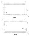
- FIG. 5is a rear view of a LED panel in accordance with one aspect of the disclosed technology
- FIG. 6is a rear perspective view of a LED panel in accordance with one aspect of the disclosed technology.
- FIG. 7is a diagrammatic illustration of a substantially flat LED panel in accordance with one aspect of the disclosed technology.
- FIG. 8is a diagrammatic illustration of a substantially flat LED panel in accordance with one aspect of the disclosed technology.
- FIG. 9is a diagrammatic illustration of a substantially flat LED panel in accordance with one aspect of the disclosed technology.
- FIG. 9Ais a diagrammatic illustration of a substantially flat LED panel in accordance with one aspect of the disclosed technology.
- FIG. 9Bis a diagrammatic illustration of a substantially flat LED panel in accordance with one aspect of the disclosed technology.
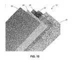
- FIG. 10is shows an exploded view of an optical stack of a LED panel in accordance with one aspect of the disclosed technology
- FIG. 11is shows an exploded view of an optical stack of a LED panel in accordance with one aspect of the disclosed technology
- FIG. 12is a rear perspective view of a LED panel in accordance with one aspect of the disclosed technology.
- FIG. 13is a rear view of a portion of a LED panel in accordance with one aspect of the disclosed technology
- FIG. 14is a diagrammatic illustration of a portion of a frame housing power circuitry in accordance with one aspect of the disclosed technology
- FIG. 14Ais a diagrammatic illustration of a portion of a frame housing power circuitry in accordance with one aspect of the disclosed technology
- FIG. 15is a rear view of a portion of a LED panel in accordance with one aspect of the disclosed technology.
- FIG. 16is a diagrammatic illustration of a portion of a frame in accordance with one aspect of the disclosed technology.
- FIG. 17is a perspective view of a portion of a LED panel in accordance with one aspect of the disclosed technology.
- FIG. 18is a perspective view of a portion of a LED panel in accordance with one aspect of the disclosed technology.
- FIG. 19is a perspective view of a portion of a LED panel in accordance with one aspect of the disclosed technology.
- FIG. 20is a perspective view of a portion of a frame in accordance with one aspect of the disclosed technology.
- FIG. 21is a perspective view of a portion of a frame in accordance with one aspect of the disclosed technology.
- FIG. 22is a perspective view of a portion of a LED panel in accordance with one aspect of the disclosed technology.
- FIG. 23is a perspective view of a portion of a LED panel in accordance with one aspect of the disclosed technology.
- FIG. 24is a diagrammatic illustration of the light fixture in accordance with one aspect of the disclosed technology.
- FIG. 25is a diagrammatic illustration of the light fixture in accordance with one aspect of the disclosed technology.
- FIG. 26is a diagrammatic illustration of the light fixture in accordance with one aspect of the disclosed technology.
- FIG. 27is a diagrammatic illustration of the light fixture in accordance with one aspect of the disclosed technology.
- FIG. 28is a diagrammatic illustration of the light fixture in accordance with one aspect of the disclosed technology.
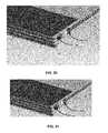
- FIG. 29is a diagrammatic illustration of a LED assembly in accordance with one aspect of the disclosed technology.
- FIG. 30is a diagrammatic illustration of a LED assembly in accordance with one aspect of the disclosed technology.
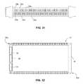
- FIG. 31is a diagrammatic illustration of a LED assembly in accordance with one aspect of the disclosed technology.
- FIG. 32is a diagrammatic illustration of the light fixture in accordance with one aspect of the disclosed technology.
- FIG. 33is a diagrammatic illustration of the light fixture in accordance with one aspect of the disclosed technology.
- FIG. 34is a diagrammatic illustration of the light fixture in accordance with one aspect of the disclosed technology.
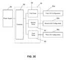
- FIG. 35is a diagrammatic illustration of the light fixture in accordance with one aspect of the disclosed technology.
- Lamp lifeis another important consideration. Service life is increasingly a driver in the development of new lamps and lighting systems. More lamp manufacturers are using life to distinguish their own products from those of their competitors.
- Lamp packagingtypically states the manufacturer's determination of lamp life, called rated life, usually in hours. The most straightforward interpretation of these ratings is arguably that they tell us how long the lamp will operate before it fails (“burns out”). But the definition of life is different for different lamp types.
- Incandescent lamp lifeis measured by operating a sample of lamps continuously in a specified position and at a specified voltage. The number of burning hours at which half the lamps have failed is considered the rated life of the lamps. Fluorescent lamps can be tested while operating at a specified temperature (e.g., 25° C./77° F.) on a continuous 3-hour-on, 20-minute-off cycle, with a standard ballast circuit that controls the current. As with incandescent lamps, rated life is the elapsed number of operating hours at which half of the lamps in a sample have burned out.
- a specified temperaturee.g. 25° C./77° F.
- LED light sourcestypically do not fail in the sense that other sources do. Over time, however, their light output can decrease until they are no longer useful for a given purpose. LEDs often last hundreds of times longer than incandescent bulbs and fluorescent tubes—up to 100,000 hours.
- LEDsrequire much smaller voltages of direct current, another factor that reduces the apparent long life of LEDs is the need for auxiliary electronics and equipment to house and operate these sources. Because electrical power commercially available in the United States is in the form of alternating current, LEDs require direct current converters. Such devices may have rated lives significantly shorter than the LEDs with which they are used. Higher voltage and high temperatures can also increase lumen depreciation in LEDs.
- substantially flat LED panel lighting fixtureshave been employed, these lighting fixtures make use of an AC-to-DC power converter module external to the fixture (e.g., extending outward from the back surface of the fixture).
- a power converter module external to the lighting fixturelimits design flexibility in integrating LED flat panel fixtures or luminaires into a range of applications, and adds complexity to installation. For example, in installations in which a lighting fixture would be surface mounted in a visible location, there would be no out-of-view place for ancillary equipment such as a power converter.
- the present disclosurerecognizes shortcomings associated with conventional fluorescent lamp and incandescent lamp lighting systems.
- the present disclosurerecognizes potential shortcomings with LED-based lighting assemblies and associated power circuitry, and provides an improved lighting fixture and associated power circuitry.
- the present disclosurerecognizes that the operating life on an entire lighting product or system must be considered, rather than just the potentially-promising long-rated life of LEDs within the lighting product or system. Besides improving the effects of lumen depreciation of LEDs, the present disclosure reduces the likelihood of catastrophic failure of other parts of the lighting product or system, including in particular a power supply or driver for the LEDs.
- the present applicationis directed to a light fixture including a light emitting diode panel and associated driving circuitry.
- the light fixtureincludes power circuitry configured to be housed within the frame of the light fixture.
- the light fixturecan include multiple configurations of light emitting diode (LED) arrays that can be operated alternately.
- the light fixturecan include multiple drivers operatively coupled to a LED array, where the drivers can be selectively operated to drive the LED array.
- the output of LED arrayscan be adjusted to maintain lumen brightness and uniformity.
- the LED panel 12is a substantially flat LED panel (also referred to simply as a LED panel).
- substantially flat LED panelas used in connection with the description of the various embodiments, is meant to include LED panels having a thickness that is substantially less than the length and width of the panel.
- LED panel fixturedenotes a light fixture 10 that incorporates a substantially flat LED panel.
- LED panel fixturesmay be of slightly non-uniform thickness due to the configuration of the LED panel or of another part of the light fixture 10 .
- an LED panel fixturecan include a frame (designated generally as 14 ) having a thickness that is greater than the thickness of the LED panel 12 .
- the light fixture 10includes a frame 14 that surrounds the LED panel 12 .
- the frame 14provides structural support, contains components of the LED panel fixture such as arrays, strips, or bars of LEDs 20 and the power circuitry (also referred to as driving circuitry, and as LED power circuitry or LED driving circuitry) (designated generally as 16 ), and provides heat dissipation.
- the framecan be configured to house or otherwise support LED power circuitry as well as associated wiring and electrical connections between the power circuitry and the LED arrays.
- the light fixture 10may take on a variety of dimensions and form factors, including, but not limited to, rectangular, other polygonal (e.g., octagonal), circular and elliptical form factors.
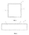
- the light fixturecan be square (see FIG. 1 ) with a size of approximately nine inches by nine inches, approximately twelve inches by twelve inches, or approximately twenty-four inches by twenty-four inches.
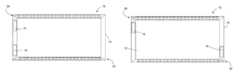
- the light fixture 10also can be rectangular with a size of approximately one foot by four feet (1 foot ⁇ 4 feet) (see FIG. 2 ) or a size of approximately two feet by four feet (2 feet ⁇ 4 feet) (see FIG. 3 ), corresponding to exemplary lower dimensions of standard fluorescent ceiling troffers.
- the light fixture 10can be sized to standard lengths for under counter or under cabinet lighting applications (e.g., twelve inches, eighteen inches, twenty-four inches, thirty-six inches, etc.).
- the LED panelcan take on any lateral size, while maintaining a relatively small thickness, without departing from the scope of the disclosed technology. This versatility in sizing provides enhanced flexibility in use in connection with a variety of applications.
- the light fixture 10can include a frame 14 , a substantially flat LED panel 12 disposed within the frame 14 and power circuitry 16 disposed or otherwise housed within the frame 14 .
- the power circuitry 16is configured to electrically couple the LED panel 12 to an external power supply (not shown), for example, via a suitable electrical connector such as a plug or socket connector 18 .
- the LED panel fixturecan be configured to provide bright, uniform light in a relatively thin package.
- the substantially flat LED panel 12can have a thickness of less than about 1.0 inches. In accordance with another embodiment, the substantially flat LED panel 12 can have a thickness of less than about 0.5 inches.
- the frame 14can be made up of four segments having mitred joints.
- the frame 14can be formed from two pieces (e.g., a top piece and a bottom piece) snapped or otherwise joined together.
- the framecan define or otherwise include stand-offs on the back of the frame (e.g., for providing ventilation when the frame is surface mounted to a support surface).
- the LED panelincludes a plurality of layers along with edge lighting disposed adjacent to at least one edge of the frame.
- the LED panelincludes an optically-transmissive panel 22 , e.g., a light guide plate or other polycarbonate or acrylic plate configured to produce even distribution of light received at edges of the optically-transmissive panel 22 .
- An array of LEDs(designated generally as 20 ) can be disposed adjacent at least one edge of the frame 14 and the optically transmissive panel 22 .
- a strip of LEDs 20may be supported adjacent to one edge of the frame 14 (e.g., disposed within a channel in the frame) and adjacent to one edge of the optically-transmissive panel 22 .
- the LED panel 12can include strips, arrays or configurations of LEDs 20 incorporated into or at least partially supported by two edges of the frame 14 . (References in this disclosure to LEDs 20 being supported by, incorporated into or adjacent an edge of the frame includes the LEDs being supported by a wall of a channel located at the edge of the frame, wherein the channel wall is offset from the edge of the frame by the width of the channel).
- the strips, arrays or configurations of LEDscan be mounted to the frame using one of a number of suitable methods.
- the LED strips or arrays 20can be secured to a portion of the frame (e.g., within a channel in the frame) using a suitable adhesive or suitable fasteners.
- the LED strips or arrays 20can be mounted to the frame in a way that controls the dissipation of heat from the LED strips or arrays to the frame. For example, it can be desirable to use the frame to dissipate some heat from LED arrays 20 , while limiting the amount of heat passing to the frame to prevent the frame from becoming too warm.
- a suitable adhesivecan be used to allow a limited amount of heat transfer from the LED arrays 20 to the frame 14 .
- metal fastenersor direct contact with the frame
- the LED panel 12can include strips, arrays or configurations of LEDs 20 incorporated into or at least partially supported by all four edges of the frame 14 .
- the LEDscan be sized and positioned such that the “emission dimension” of the LED elements has the same thickness or slightly less thickness than the thickness of the light input edge of the optically-transmissive panel, thereby allowing for an extremely thin profile.
- the LEDsmay include optical coupling structures such as lenses or reflectors that direct light emitted by the LEDs into an edge of optically-transmissive panel 22 .
- the LED panel 12can include a diffuser film 24 disposed on a first side of the optically-transmissive panel 22 , e.g., below the optically transmissive panel 22 when the fixture is mounted horizontally for a ceiling lighting application.
- the outer diffuser film 24is configured to provide uniform light output, and can be made of any suitable material.
- the outer diffuser film 24can be a weatherable film.
- the outer diffuser film 24can be configured as a soft film or as a hard, abrasion-resistant film depending upon the particular application.
- the outer diffuser film 24can be made waterproof or moisture proof depending upon the desired application.
- the LED panel 12can include a brightness enhancement film (BEF) 26 disposed on a second side of the optically-transmissive panel 22 , e.g., above the optically-transmissive panel 22 when the fixture is mounted horizontally for a ceiling lighting application.
- BEFbrightness enhancement film
- the brightness enhancement film 26can be configured to collimate light along a vertical axis to improve the overall light output from the LED panel 12 .
- the LED panelcan be configured to include multiple BEFs optimized for the particular arrangement of LEDs along one or more edges of the LED panel.
- the LED panelcan include an optically-transmissive panel in the form of a light guide plate with a first array of LEDs incorporated into a first side of the frame adjacent a first side of the light guide plate, the first array of LEDs emitting light focused along a first direction, and a second array of LEDs incorporated into a second side of the frame adjacent a second side of the light guide plate, the second array of LEDs emitting light focused along a second direction that is opposite the first direction.
- the substantially flat LED panelcan include a first brightness enhancement film (BEF) positioned adjacent the light guide plate and configured to collimate light emitted by the first array of LEDs, and a second BEF positioned adjacent the first BEF and configured to collimate light emitted by the second array of LEDs.
- BEFbrightness enhancement film
- the LED panel 12can include a reflector 28 positioned on the other side of the BEF 26 (e.g., above the BEF 26 ) when the fixture is mounted horizontally (e.g., for a ceiling lighting application).
- the reflector 28is configured and position to return a portion of the light emitted by the optically-transmissive panel 22 in a direction opposite the intended output direction, thereby providing enhanced total light output.
- the substantially flat LED panel 12includes a backing 30 , e.g., a sheet metal backing disposed adjacent the other side of the reflector 28 .
- a sheet metal backing 30 in combination with a metallic (e.g. aluminum) frame 14can provide excellent dissipation of heat generated by the LEDs.
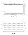
- FIG. 9Bshows an embodiment in which an array of LEDs (e.g., a full array of LEDs) is disposed across most or substantially all of the area of an optically-transmissive panel, while receiving power from edge-mounted power circuitry within the frame of the flat panel lighting fixture.
- the panelcan incorporate rows of LEDs at one face of the optically-transmissive panel, wherein the LEDs in each row are electrically coupled by a power line to a driver located at the edge of the LED fixture.
- the light fixture 10includes power circuitry 16 disposed or otherwise housed within the frame 14 , where the power circuitry 16 is configured to electrically couple the LED panel 12 to an external power source (e.g., via a suitable electrical connector 18 ).
- the power circuitry 16is configured to electrically couple the LED panel 12 to an external power source (e.g., via a suitable electrical connector 18 ).
- this embodimentserves to provide an LED panel fixture with an extremely thin form factor that can be easily mounted to a flat surface, such as a wall, an underside of a cabinet or the like. As shown in FIGS.
- the light fixture 10can be configured to include first and second LED strips, bars, arrays or configurations (designated generally as 20 ) disposed on opposite sides of the frame 14 , along with power circuitry in the form of a pair of LED drivers 16 positioned in one or both of the remaining sides of the rectangular frame.
- the illustrated embodimentshows a first LED driver 16 electrically coupled to and configured to control a first LED array (e.g., an LED strip 20 ), along with a second LED driver 16 coupled to and configured to control the second LED array (e.g., an LED strip).
- the light fixtureincludes power circuitry 16 disposed within or otherwise housed by the frame, where the power circuitry 16 is configured to electrically couple the LED panel 12 to an external power source.
- the power circuitrywill be configured to have a relatively long and narrow form factor, allowing it to be housed within a portion of a frame.
- FIGS. 14-18show exemplary embodiments of the power circuitry 16 , or portions of the power circuitry disposed or otherwise housed within a portion the frame 14 .
- the power circuitry(or component boards of the power circuitry) can have a length and a width, where the length-to-width ratio is at least 5-to-1.
- the power circuitrycan have a length-to-width ratio of at least 10-to-1.
- the frame 14can be configured to define or otherwise provide one or more channels to support aspects of the power circuitry, the associated wiring as well as LED arrays or bars.
- a portion of the framemay be configured to define a channel 40 (e.g., a channel designated as a first channel or a second channel) sized to house a portion of the power circuitry 16 .
- the first channel 40 within a portion of the framecan be configured to house power circuitry (e.g., LED driver circuitry) having dimensions of approximately twelve inches in length, approximately one inch of width and approximately one half inch in height. It will be appreciated that the disclosed technology is not limited to these exemplary dimensions.
- the first channel 40can take on other dimensions without departing from the scope of the disclosed technology.
- Such compact power and control circuitrycan be obtained by employing miniaturized power and/or control boards.
- a programmable logic controller (PLC) motherboardcan serve as a real-time clock with timing control logic to regulate operation of the LED arrays.
- PLCprogrammable logic controller
- This motherboardmay operate in coordination with one or more daughterboards, which are disposed or otherwise housed within the frame (e.g., within a first or second channel defined by a portion of the frame) to provide additional functionality.
- a sensor modulecan process signals from one or more sensors within the light fixture (e.g., a sensor to determine the intensity and/or color temperature of light being emitted by the light fixture) (see, for example, FIGS. 22-23 ). Output from these sensors can be used, for example, to control the output intensity of the lighting fixture in the case of lumen depreciation for some or all of the LEDs within the lighting fixture.
- sensors within the light fixturee.g., a sensor to determine the intensity and/or color temperature of light being emitted by the light fixture
- infrared sensorsmay be used for remote control dimming.
- ambient light sensorsmay be employed to provide automatic adjustment to dimming.
- the light fixturecan be configured to receive external inputs to control operation, such as signals from an associated security camera or motion sensor system
- Multiple control modulesmay be distributed within the frame for efficient use of space.
- two primary driversmay be disposed or otherwise housed at opposite edges of the frame and one or more input/output modules can be housed at a transverse edge of the frame.
- FIG. 14Athe use of miniaturized circuit elements permits multiple power supply or control modules to be arrayed within a given channel 40 of the frame 14 .
- Three power supply modules 16 A, 16 B, and 16 Care arrayed within the channel. As shown these are separate circuit elements, but multiple power supply or control modules also can be integrated on a single circuit board.
- Respective power supply circuitscan be electrically coupled to different sets of LEDs within an array of LEDs (not shown in FIG. 14A ).
- This arrangementpermits the DC voltage and current output specifications of each power supply circuit to be matched to input requirements of a subset of the LEDs within the LED array, while making efficient use of limited space within frame 14 . Further, this arrangement can facilitate under-driving an array of LEDs to allow for increased driving in the case of lumen depreciation.
- the frame or a portion of the frame 14can be configured to define another channel 42 (e.g., a channel designated as a first channel or a secondary channel) for housing wiring or other electrical connectors associated with the light fixture.
- portions of the framecan include a channel 42 to support a number of wires connecting the LED arrays to the driving circuitry.
- a channelcan be defined to house embedded conductive traces to conserve space within the frame.
- cables or other conventional wiringcan be used at other locations around the frame, such as interconnecting an LED bar and driving circuitry at a corner of the frame or at another area in the frame where power circuitry or driver circuitry is not present.
- the driving circuitrycan be tailored or otherwise customized to support the relatively long, but narrow, geometry of the driving circuitry.
- space-sensitive componentssuch as capacitors and the like, can be oriented along the long direction of the power circuitry footprint.
- printed circuit boards associated with the power circuitrycan be configured to include multi-layers in which conductive layers and/or conductive traces are stacked between insulating material.
- multiple circuit modulescan be arrayed at a given channel or edge area of frame 14 .
- the frame or a portion of the framecan be configured to yet another channel 44 (e.g., a channel designated as a third channel) for housing a supporting arrays or strips of LEDs 20 .
- yet another channel 44e.g., a channel designated as a third channel
- housing the power circuitry within the framecan provide an LED panel fixture with an extremely thin form factor that can be easily mounted to a flat surface, such as a wall, an underside of a cabinet or the like.
- the light fixture 10can be configured to include first and second LED strips or bars 20 disposed on opposite sides of the frame 14 , along with power circuitry in the form of a pair of LED drivers positioned in one or both of the remaining sides of the rectangular frame.
- the illustrated exemplary embodimentsshows a first LED driver electrically coupled to and configured to control a first LED array along with a second LED driver coupled to and configured to control the second LED array.
- FIG. 9shows an alternative light fixture 10 with the first and second LED arrays disposed on opposite sides of the frame 14 (e.g., on a top side of the frame and a bottom side of the frame in the orientation provided in the figure), and with a pair of LED drivers positioned on both remaining sides of the frame.
- LED strips or bars 20are located at different sides of the frame 14 than LED drivers 16 . As seen in FIG. 9A , it is also possible to locate the LED drivers 16 on the same sides of the frame as the LED strips 20 . This arrangement makes less efficient use of the space at the edges of frame 14 , but may simplify electrical connection of drivers 16 to LED strips 20 .
- the light fixturecan include multiple sets or configurations of LEDs.
- the light fixturecan be configured to include a first set or configuration of LEDs 20 a and a second set or configuration of LEDs 20 b along with power circuitry (also referred to as driving circuitry) 16 operatively coupled to the first set of LEDs 20 a and the second set of LEDs 20 b and an associated power supply (designated generally as 50 ), for example, a standard AC power supply found in a home or office setting, wherein the driving circuitry 16 is configured to selectively power the first set of LEDs 20 a and the second set of LEDs 20 b in an alternating manner.
- power circuitryalso referred to as driving circuitry
- the power circuitry 16can include a first driver 52 operatively coupled to the first LED configuration 20 a and a second driver 54 operatively coupled to the second LED configuration 20 b .
- the power circuitry 16can include a controller 56 operatively coupled to the first driver 52 and the second driver 54 , and configured to selectively operate the first driver 52 and the second driver 54 to control the first configuration of LEDs 20 a and the second configuration of LEDs 20 b in a desired manner.
- FIG. 27shows another exemplary embodiment in which switching circuitry 58 is operatively coupled to the first driver 52 and the second driver 54 , and configured to selectively activate the first configuration of LEDs 20 a and the second configuration of LEDs 20 b .
- FIG. 28shows yet another exemplary embodiment in which the controller 56 is operatively coupled to the first driver 52 and the second driver 54 to selectively control operation of the first driver 52 and the second driver 54 , as well as monitor the first driver 52 and the second driver 54 to ensure that the respective drivers are functioning properly. This embodiment will be discussed in greater detail below.
- the first set or configuration of LEDs 20 a and the second set or configuration of LEDs 20 bare driven alternately.
- the first configuration of LEDs 20 ais active
- the second configuration of LEDs 20 bcan be set to inactive and vice versa.
- the first and second configurations of LEDscan be driven cyclically, for example, repeated over periods of time where the “on” cycle time for the first set of LEDs is identical or substantially identical to the “on” cycle time for the second set of LEDs. It will be appreciated that permitting the LEDs adequate time to cool can extend the operating life of the LEDs, thereby potentially extending the operating life of the light fixture. It also will be appreciated that various timing cycles can be implemented within the scope of the disclosed technology.
- the first set of LEDs 20 acan be on for a twenty-four hour period and off for the next twenty-four hour period, where the second set of LEDs 20 b is on.
- the first and second configurations of LEDscan be implemented in a number of ways without departing from the scope of the disclosed technology.
- the first configuration of LEDs 20 a and the second configuration of LEDs 20 bcan be arranged in a single strip or bar in which a single row of LED elements are arrayed in an alternating arrangement (e.g., A BAB arrangement, where A corresponds to an LED within the first LED configuration 20 a and B corresponds to an LED within the second LED configuration 20 b ).
- the LEDsmay be disposed in or otherwise arranged in a two-strip bar in which the first configuration of LEDs 20 a is included along the top row and the second configuration of LEDs 20 b is included along the bottom row.
- the LEDscan be arranged in a two-strip or two-row formation such that the first strip includes alternating arrangements of LEDs from the first configuration of LEDs 20 a and the second configuration of LEDs 20 b , and the second row of LEDs includes alternating arrangements from the first configuration of LEDs 20 a and the second configuration of LEDs 20 b . It will be appreciated that in these two-row arrangements, the traditional two-wire power supply for a single row of LEDs operated together would be replaced by at least a four-wire power supply.
- the light fixturecan be configured to have a first row of LEDs disposed on one side of the frame and a second set of LEDs disposed on an opposite side of the frame where the first set of LEDs and the second set of LEDs are driven alternately according to a predetermined time cycle.
- the first set of LEDs 20 acan include a row or array of LEDs on one side of the frame and another row or array of LEDs on the opposite side of the frame.
- the second set of LEDscan be configured to include a first row of LEDs on one side of the frame disposed between the two sides used for the first set.
- the light fixturecan include a first array of LEDs having alternating LEDs from the first set and the second set, with a mirror image configuration on the opposite side of the frame.
- the light fixturecan be configured to include multiple drivers per LED configuration.
- a first driver 52 and a second driver 54can be selectively operatively coupled to the LED configuration 20 together with appropriate switching or controlling circuitry 56 .
- a first driver 52would be selected to electrically couple the LED configuration to the power supply 50 .
- Fault detection circuitrye.g., incorporated into the controller 56
- the controller or switching circuitry 56can then switch over to the second driver 54 such that the second driver 54 electrically couples the LED configuration 20 to the associated power supply 50 .
- the light fixturecan incorporate more than two configurations of LEDs, with a respective driver for each configuration of LEDs.
- the power circuitry 16can include a first driver 52 operatively coupled to the first LED configuration 20 a , a second driver 54 operatively coupled to the second LED configuration 20 b , and a third driver 60 operatively coupled to the third LED configuration 20 c .
- the power circuitry 16can include a controller 56 operatively coupled to the first driver 52 , the second driver 54 and the third driver 60 , and configured to selectively operate the first driver 52 , the second driver 54 and the third driver 56 , thereby to control the first, second and third configurations of LEDs 20 a , 20 b , 20 c in a desired manner.
- the first, second and third configurations of LEDscan be driven cyclically, for example, repeated over periods of time where the “on” cycle time for the first set of LEDs is identical or substantially identical to the “on” cycle time for the second set of LEDs and the “on” cycle time for the third set of LEDs.
- the second configuration of LEDs 20 b and third configuration of LEDscan be set to inactive.
- two configurations of LEDscan be set to active during a given time period, while the third can be set to inactive.
- the configurationscan be arranged in a manner consistent with the descriptions of two configurations above.
- the first, second and third configurations of LEDscan be arranged in an alternating manner and/or in alternating strips or arrays.
- the first drivercan be selectively operatively coupled to both the first LED configuration and the second LED configuration.
- the second drivercan be selectively operatively coupled to the second LED configuration as well as the first LED configuration.
- the associated control and/or switching circuitrycan be configured to monitor any fault conditions with one of the drivers and effectively switch the second driver over to control operation of the first and/or second LED configuration in the case of a malfunction in the first driver.
- FIG. 28shows an embodiment implementing this concept except that the embodiment of FIG.
- the controller 56provides similar functionality as that described above with respect to FIG. 33 .
- LED-based configurationsmay be employed.
- arrays of LEDsmay be employed in connection with other focusing and/or brightness-enhancement optical elements besides those described above with respect to the various figures.
- the LED panelcan include a plurality of LEDs having outputs of various colors and/or color temperatures.
- the substantially flat LED panelcan include white LEDs having output of a predetermined color temperature.
- the substantially flat LED panelcan include multiple arrays of white LEDs having outputs of different color temperatures. These multiple arrays can be selectively energized to provide a “white light” of a variable color temperature. Alternatively, the multiple arrays can be selectively energized to maintain a desired overall lumen output to address or otherwise compensate for lumen degradation.
- the substantially flat LED panelcan include a plurality of colored LEDs (e.g., LEDs having red output, green output and blue output), where the colored LEDs are configured to cooperate to produce white light when energized.
- the light fixturecan include control circuitry that is configured to selectively energize the colored LEDs to provide light output of variable color temperature.
- the control circuitryalso can be configured to control the intensity of the light emitted by the substantially flat LED panel, thereby providing a dimming function.
- both configurationscan be activated at the same time. For example, if an ambient light sensor of light fixture 10 detects brightness below a desired threshold value, light fixture 10 can activate two (or more, if available) configurations of LEDs at the same time. Alternatively, a stepping function can be applied to selectively energize multiple configurations of LEDs.
- the LED panelcan include one or more strips of LEDs disposed adjacent and least one edge of the frame, where each strip of LEDs is removably coupled to the power circuitry via a suitable electrical connector. It will be appreciated that this configuration allows for the easy replacement of one or more strips of LEDs within the substantially flat LED panel. For example, in the case of LED failure or burnout, the strip of LEDs could be easily replaced without replacing the entire fixture. In addition, the color output of the light fixture could be altered by swapping out one or more of the LED strips. For example, a holiday effect could be achieved by removing a strip of white LEDs and replacing the strip of white LEDs with colored LEDs.
- the framecan be provided with one or more sections that can be detached or otherwise separated from the remainder of the frame.
- a cover section of the frame containing an LED stripmay include a hinged connection to the remainder of the frame, and a pull tab. The user would pull open the cover section of the frame in order to uncover the LED strip for replacement.
- the light fixtureincludes at least one mounting member configured to mount (e.g., removably or permanently mount) the frame to a support surface.
- the mounting membermay take on numerous forms depending on the desired application.
- the mounting membercan be configured to mount the frame to a substantially vertical support surface, such as a wall.
- the mounting membermay include suitable clips, brackets or the like configured to anchor the light fixture to a wall in a home, a wall in a hotel, a wall in a parking garage or the like.
- the mounting membercan be configured to mount the frame to a substantially horizontal support surface, such as a ceiling, the underside of a cabinet or the like.
- Examples of other applicationsinclude, but are not limited to, stairwell lighting, emergency lighting (optionally including a battery backup), task lighting for cubicles, under counter lighting (e.g., kitchen work areas and within china cabinets), home or commercial garage lighting, lighting for retail shelving, aquarium lighting, and the like.
- the light fixturecan be employed in a retrofit kit to retrofit an existing fluorescent lighting unit.
- the light fixturecan be arranged and/or installed together with a plurality of light fixtures where a primary light fixture is electrically coupled to an external power supply and other light fixtures can be coupled to the external power supply by way of the primary light fixture (so called “daisy chaining”).
- Examples of applicationsinclude, but are not limited to, stairwell lighting, emergency lighting (optionally including a battery backup), task lighting for cubicles, under counter lighting (e.g., kitchen work areas and within china cabinets), home or commercial garage lighting, lighting for retail shelving, aquarium lighting, and the like.
- stairwell lightingemergency lighting (optionally including a battery backup)
- task lighting for cubiclesunder counter lighting (e.g., kitchen work areas and within china cabinets), home or commercial garage lighting, lighting for retail shelving, aquarium lighting, and the like.
- edge lightingallows for thin panels of flexible length and width providing uniform light output.
Landscapes
- Physics & Mathematics (AREA)
- Engineering & Computer Science (AREA)
- General Engineering & Computer Science (AREA)
- Optics & Photonics (AREA)
- General Physics & Mathematics (AREA)
- Microelectronics & Electronic Packaging (AREA)
- Nonlinear Science (AREA)
- Power Engineering (AREA)
- Crystallography & Structural Chemistry (AREA)
- Chemical & Material Sciences (AREA)
- Mathematical Physics (AREA)
- Non-Portable Lighting Devices Or Systems Thereof (AREA)
- Arrangement Of Elements, Cooling, Sealing, Or The Like Of Lighting Devices (AREA)
- Circuit Arrangement For Electric Light Sources In General (AREA)
- Planar Illumination Modules (AREA)
- Fastening Of Light Sources Or Lamp Holders (AREA)
Abstract
Description
Claims (20)
Priority Applications (1)
| Application Number | Priority Date | Filing Date | Title |
|---|---|---|---|
| US14/618,665US9335036B2 (en) | 2011-05-17 | 2015-02-10 | Flat panel lighting device and driving circuitry |
Applications Claiming Priority (5)
| Application Number | Priority Date | Filing Date | Title |
|---|---|---|---|
| US201161487253P | 2011-05-17 | 2011-05-17 | |
| US201161579472P | 2011-12-22 | 2011-12-22 | |
| US13/473,929US20120320627A1 (en) | 2011-05-17 | 2012-05-17 | Flat panel lighting device and driving circuitry |
| US14/497,943US9423113B2 (en) | 2011-05-17 | 2014-09-26 | Flat panel lighting device and driving circuitry |
| US14/618,665US9335036B2 (en) | 2011-05-17 | 2015-02-10 | Flat panel lighting device and driving circuitry |
Related Parent Applications (1)
| Application Number | Title | Priority Date | Filing Date |
|---|---|---|---|
| US14/497,943ContinuationUS9423113B2 (en) | 2011-05-17 | 2014-09-26 | Flat panel lighting device and driving circuitry |
Publications (2)
| Publication Number | Publication Date |
|---|---|
| US20150153031A1 US20150153031A1 (en) | 2015-06-04 |
| US9335036B2true US9335036B2 (en) | 2016-05-10 |
Family
ID=46246190
Family Applications (14)
| Application Number | Title | Priority Date | Filing Date |
|---|---|---|---|
| US13/473,929AbandonedUS20120320627A1 (en) | 2011-05-17 | 2012-05-17 | Flat panel lighting device and driving circuitry |
| US13/473,918Active2032-07-24US8915636B2 (en) | 2011-05-17 | 2012-05-17 | Flat panel lighting device and retrofit kit |
| US14/480,262Expired - Fee RelatedUS9447954B2 (en) | 2011-05-17 | 2014-09-08 | Light fixture having a central wire-way |
| US14/480,772ActiveUS9562678B2 (en) | 2011-05-17 | 2014-09-09 | Flat panel lighting device |
| US14/497,943Expired - Fee RelatedUS9423113B2 (en) | 2011-05-17 | 2014-09-26 | Flat panel lighting device and driving circuitry |
| US14/554,919AbandonedUS20150085528A1 (en) | 2011-05-17 | 2014-11-26 | Flat panel lighting device and driving circuitry |
| US14/618,665Expired - Fee RelatedUS9335036B2 (en) | 2011-05-17 | 2015-02-10 | Flat panel lighting device and driving circuitry |
| US15/092,186ActiveUS9453616B2 (en) | 2011-05-17 | 2016-04-06 | Flat panel lighting device |
| US15/158,353ActiveUS9441801B1 (en) | 2011-05-17 | 2016-05-18 | Flat panel lighting device and driving circuitry |
| US15/209,142ActiveUS9664365B2 (en) | 2011-05-17 | 2016-07-13 | Flat panel lighting device |
| US15/241,744Expired - Fee RelatedUS9523487B1 (en) | 2011-05-17 | 2016-08-19 | Flat panel lighting device and driving circuitry |
| US15/381,974ActiveUS9976732B2 (en) | 2011-05-17 | 2016-12-16 | Flat panel lighting device and driving circuitry |
| US15/603,281Active2032-07-22US10422518B2 (en) | 2011-05-17 | 2017-05-23 | Flat panel lighting device |
| US15/983,943ActiveUS10364974B2 (en) | 2011-05-17 | 2018-05-18 | Flat panel lighting device and driving circuitry |
Family Applications Before (6)
| Application Number | Title | Priority Date | Filing Date |
|---|---|---|---|
| US13/473,929AbandonedUS20120320627A1 (en) | 2011-05-17 | 2012-05-17 | Flat panel lighting device and driving circuitry |
| US13/473,918Active2032-07-24US8915636B2 (en) | 2011-05-17 | 2012-05-17 | Flat panel lighting device and retrofit kit |
| US14/480,262Expired - Fee RelatedUS9447954B2 (en) | 2011-05-17 | 2014-09-08 | Light fixture having a central wire-way |
| US14/480,772ActiveUS9562678B2 (en) | 2011-05-17 | 2014-09-09 | Flat panel lighting device |
| US14/497,943Expired - Fee RelatedUS9423113B2 (en) | 2011-05-17 | 2014-09-26 | Flat panel lighting device and driving circuitry |
| US14/554,919AbandonedUS20150085528A1 (en) | 2011-05-17 | 2014-11-26 | Flat panel lighting device and driving circuitry |
Family Applications After (7)
| Application Number | Title | Priority Date | Filing Date |
|---|---|---|---|
| US15/092,186ActiveUS9453616B2 (en) | 2011-05-17 | 2016-04-06 | Flat panel lighting device |
| US15/158,353ActiveUS9441801B1 (en) | 2011-05-17 | 2016-05-18 | Flat panel lighting device and driving circuitry |
| US15/209,142ActiveUS9664365B2 (en) | 2011-05-17 | 2016-07-13 | Flat panel lighting device |
| US15/241,744Expired - Fee RelatedUS9523487B1 (en) | 2011-05-17 | 2016-08-19 | Flat panel lighting device and driving circuitry |
| US15/381,974ActiveUS9976732B2 (en) | 2011-05-17 | 2016-12-16 | Flat panel lighting device and driving circuitry |
| US15/603,281Active2032-07-22US10422518B2 (en) | 2011-05-17 | 2017-05-23 | Flat panel lighting device |
| US15/983,943ActiveUS10364974B2 (en) | 2011-05-17 | 2018-05-18 | Flat panel lighting device and driving circuitry |
Country Status (8)
| Country | Link |
|---|---|
| US (14) | US20120320627A1 (en) |
| EP (1) | EP2710293B8 (en) |
| JP (2) | JP6216713B2 (en) |
| KR (1) | KR20140038460A (en) |
| CN (2) | CN103534527A (en) |
| CA (1) | CA2835213A1 (en) |
| TW (1) | TWI597454B (en) |
| WO (2) | WO2012158894A2 (en) |
Cited By (8)
| Publication number | Priority date | Publication date | Assignee | Title |
|---|---|---|---|---|
| US20160102852A1 (en)* | 2011-07-26 | 2016-04-14 | Jabil Circuit, Inc. | Led lighting assembly having electrically conductive heat sink for providing power directly to an led light source |
| US20160146448A1 (en)* | 2014-11-20 | 2016-05-26 | Ming-Hsiao Ma | Interactive sensing and displaying building assembly |
| US20170097147A1 (en)* | 2011-05-17 | 2017-04-06 | Pixi Lighting, Inc. | Flat panel lighting device and driving circuitry |
| US20190017660A1 (en)* | 2017-07-17 | 2019-01-17 | Kanghong Zhang | Intermediate driver mount |
| US10215911B2 (en) | 2013-04-17 | 2019-02-26 | Unity Opto Technology Co., Ltd. | Lighting assembly |
| US10330291B2 (en) | 2016-07-26 | 2019-06-25 | Cordelia Lighting Inc. | Hidden mounting system for luminaire |
| US10451258B1 (en) | 2018-09-20 | 2019-10-22 | Chia-Teh Chen | Lighting fixture |
| US10900657B2 (en) | 2017-08-01 | 2021-01-26 | Technical Consumer Products, Inc. | Edge-lit light fixture having capabilities for a secondary service |
Families Citing this family (159)
| Publication number | Priority date | Publication date | Assignee | Title |
|---|---|---|---|---|
| GB2484713A (en) | 2010-10-21 | 2012-04-25 | Optovate Ltd | Illumination apparatus |
| US20130033861A1 (en)* | 2011-08-01 | 2013-02-07 | Kevin Orton | Retrofit LED light Panel |
| JP6217957B2 (en)* | 2011-09-29 | 2017-10-25 | 東芝ライテック株式会社 | Lighting device |
| US20140029240A1 (en)* | 2012-07-24 | 2014-01-30 | Shenzhen China Star Optoelectronics Technology Co. Ltd. | Backlight System and Flat Panel Display Device |
| US9157678B2 (en) | 2013-02-07 | 2015-10-13 | Whirlpool Corporation | Power supplies for lighted shelves in a refrigerator |
| US9528754B2 (en)* | 2013-02-07 | 2016-12-27 | Whirlpool Corporation | Configurable power supply circuit for lighted shelves in a refrigerator |
| EP2767753A1 (en)* | 2013-02-18 | 2014-08-20 | LD Lichtdominanz GmbH | Light panel operating on the basis of light-emitting diode chips |
| JP6118427B2 (en)* | 2013-02-19 | 2017-04-19 | フィリップス ライティング ホールディング ビー ヴィ | Method and apparatus for controlling lighting |
| US20140301074A1 (en)* | 2013-03-06 | 2014-10-09 | Lynk Labs, Inc. | Led lighting system, method, and apparatus |
| US9666744B2 (en) | 2013-03-15 | 2017-05-30 | Cooper Technologies Company | Edgelit multi-panel lighting system |
| US9476552B2 (en)* | 2013-04-17 | 2016-10-25 | Pixi Lighting, Inc. | LED light fixture and assembly method therefor |
| US9546781B2 (en) | 2013-04-17 | 2017-01-17 | Ever Venture Solutions, Inc. | Field-serviceable flat panel lighting device |
| US20140313780A1 (en)* | 2013-04-17 | 2014-10-23 | Pixi Lighting, Inc. | Field-serviceable flat panel lighting device |
| EP2997299A4 (en) | 2013-04-19 | 2017-03-08 | Cooper Technologies Company | Multi-wing edge-lit structure |
| USD744138S1 (en) | 2013-04-19 | 2015-11-24 | Cooper Technologies Company | Modular edgelit luminaire |
| CA2913132A1 (en) | 2013-05-23 | 2014-11-27 | Intellilum, Llc | Retrofit led fixtures for replacing fluorescent trollers |
| US9188733B2 (en) | 2013-06-07 | 2015-11-17 | Steelcase Inc. | Panel light assembly |
| ITTV20130101A1 (en)* | 2013-06-21 | 2014-12-22 | Monica Mazzoli | "LIGHT AND PANEL DECORATIVE DEVICE, OF THE EDGE - LIT TYPE" |
| EP3017659B1 (en) | 2013-07-02 | 2018-01-10 | Philips Lighting Holding B.V. | Methods and apparatus for lifetime extension of led-based lighting units |
| US20150153028A1 (en)* | 2013-07-25 | 2015-06-04 | Limited Liability Company "Dis Plus" | Housing for led lighting device |
| USD751648S1 (en) | 2013-08-21 | 2016-03-15 | Cooper Technologies Company | Light-emitting diode edge lighted airfield guidance sign |
| US9495892B2 (en) | 2013-08-21 | 2016-11-15 | Cooper Technologies Company | Light-emitting diode edge lighted airfield guidance sign |
| KR102296556B1 (en) | 2013-09-25 | 2021-09-02 | 실리콘 힐 비.브이. | Led lighting system |
| USD915632S1 (en) | 2013-11-15 | 2021-04-06 | 3Form, Llc | Baffle with reduced height |
| USD917079S1 (en) | 2013-11-15 | 2021-04-20 | 3Form, Llc | Thin baffle |
| US10889987B2 (en) | 2017-05-19 | 2021-01-12 | 3Form, Llc | Felt baffle with snap ends |
| USD959030S1 (en) | 2013-11-15 | 2022-07-26 | 3Form, Llc | Baffle with slit end |
| USD916348S1 (en)* | 2013-11-15 | 2021-04-13 | 3Form, Llc | Light-weight lighting fixture |
| GB2520344B (en)* | 2013-11-19 | 2015-10-14 | Kosnic Lighting Ltd | LED luminaire |
| USD742581S1 (en)* | 2013-12-09 | 2015-11-03 | Kenall Manufacturing Company | Driver housing |
| US9195281B2 (en) | 2013-12-31 | 2015-11-24 | Ultravision Technologies, Llc | System and method for a modular multi-panel display |
| TW201530049A (en)* | 2014-01-20 | 2015-08-01 | Lextar Electronics Corp | Panel light |
| US9857072B2 (en)* | 2014-03-12 | 2018-01-02 | American Heating Technologies Inc. | Apparatuses, methods, and systems for illuminating panels used as cabinet doors and drawer panels |
| JP6410076B2 (en)* | 2014-03-28 | 2018-10-24 | シーシーエス株式会社 | Power supply device and LED lighting device |
| US9835300B2 (en) | 2014-05-22 | 2017-12-05 | Feit Electric Company, Inc. | Multi-configurable light emitting diode (LED) flat panel lighting fixture |
| US9927103B2 (en) | 2014-05-22 | 2018-03-27 | Feit Electric Company, Inc. | Flush mount lighting fixture |
| GB2526376B (en)* | 2014-05-23 | 2016-04-06 | Julie Claire Company Ltd | A light panel light source shade |
| EP3174612B1 (en) | 2014-08-01 | 2019-09-04 | Smart Billiard Lighting LLC | Billiard table lighting and game play monitor |
| US9709249B2 (en)* | 2014-10-08 | 2017-07-18 | Checkers Industrial Products, Llc | Arrow board light and touch controller |
| KR20160047037A (en)* | 2014-10-21 | 2016-05-02 | 삼성디스플레이 주식회사 | Display device |
| USD915631S1 (en) | 2014-11-14 | 2021-04-06 | 3Form, Llc | Baffle with closed ends |
| DE102015100842A1 (en) | 2015-01-21 | 2016-07-21 | Tailorlux Gmbh | Lighting device with a phosphor layer and different light emitting diodes |
| WO2016151125A1 (en) | 2015-03-26 | 2016-09-29 | Silicon Hill B.V. | Led lighting system |
| US9557022B2 (en) | 2015-04-30 | 2017-01-31 | Ever Venture Solutions, Inc. | Non-round retrofit recessed LED lighting fixture |
| US10502376B2 (en) | 2015-05-01 | 2019-12-10 | Hubbell Incorporated | Luminaire with independently controlled light output |
| CA2983117C (en)* | 2015-05-01 | 2021-12-21 | Hubbell Incorporated | Luminaire with independently controlled light output |
| USD915634S1 (en) | 2015-05-28 | 2021-04-06 | 3Form, Llc | Tall baffle |
| CN204879507U (en)* | 2015-06-05 | 2015-12-16 | 光明世界科技有限公司 | Easy to install lamps |
| TWM514536U (en)* | 2015-07-01 | 2015-12-21 | Lextar Electronics Corp | Plane light |
| CA2991319A1 (en) | 2015-07-08 | 2017-01-12 | Performance Indicator, Llc | Led panel lighting system |
| CN105072743A (en)* | 2015-07-29 | 2015-11-18 | 广西理工职业技术学院 | Special remote-controlled intelligent LED desk lamp for students |
| US9668329B2 (en)* | 2015-09-07 | 2017-05-30 | Qisda Corporation | Method for operating an electronic device to increase light density and electronic device thereof |
| JP6626670B2 (en)* | 2015-09-07 | 2019-12-25 | アイリスオーヤマ株式会社 | Lighting equipment fixture structure |
| KR101683624B1 (en) | 2015-11-12 | 2016-12-21 | (주)프리모 | LED lamp for vehicle |
| US10274144B2 (en)* | 2015-12-15 | 2019-04-30 | Radiant Opto-Electronics (Suzhou) Co., Ltd. | Lamp, lamp system and method for assembling lamp system |
| CN106885186B (en)* | 2015-12-15 | 2019-03-15 | 瑞仪光电(苏州)有限公司 | Lamps and lanterns |
| KR101641126B1 (en)* | 2016-01-21 | 2016-07-20 | 엘이디라이팅 주식회사 | Surface light emitting device using light emitting diode |
| US10295721B1 (en)* | 2016-03-02 | 2019-05-21 | Amazon Technologies, Inc. | Adjustable color temperature illumination |
| KR102048315B1 (en)* | 2016-04-15 | 2019-11-25 | 선전 로욜 테크놀로지스 컴퍼니 리미티드 | Lighting device and its control method |
| US10125925B2 (en)* | 2016-06-23 | 2018-11-13 | MaxLite, Inc. | Solid state hid canopy light fixture retrofit assembly |
| US10047937B2 (en) | 2016-06-29 | 2018-08-14 | Feit Electric Company, Inc. | Lighting fixture mounting systems |
| US10634320B2 (en) | 2016-06-29 | 2020-04-28 | Feit Electric Company, Inc. | Lighting fixture mounting systems |
| US9741273B1 (en) | 2016-08-10 | 2017-08-22 | Jeffrey A. Curtis | Illuminated assemblies and methods of manufacture thereof |
| US9835307B1 (en)* | 2016-08-17 | 2017-12-05 | The LED Source, Inc. | Retrofit LED light panel |
| US10591115B2 (en) | 2016-08-18 | 2020-03-17 | c2 Semiconductor, LLC | Retrofit kit and methods for conversion of fluorescent light assemblies to LED assemblies |
| US20180090059A1 (en)* | 2016-09-23 | 2018-03-29 | Mahdi Farrokh Baroughi | Micro light emitting diode testing |
| US9801250B1 (en) | 2016-09-23 | 2017-10-24 | Feit Electric Company, Inc. | Light emitting diode (LED) lighting device or lamp with configurable light qualities |
| US10893587B2 (en) | 2016-09-23 | 2021-01-12 | Feit Electric Company, Inc. | Light emitting diode (LED) lighting device or lamp with configurable light qualities |
| USD841869S1 (en)* | 2016-09-28 | 2019-02-26 | Ningbo Royalux Lighting Co., Ltd. | Light-emitting diode pendant lamp |
| ES2665618B1 (en)* | 2016-10-26 | 2019-02-07 | Univ Valladolid | Omnidirectional LED modular luminaire |
| US10375798B2 (en)* | 2016-10-26 | 2019-08-06 | Enlighted, Inc. | Self-determining a configuration of a light fixture |
| EP3339951A1 (en) | 2016-12-20 | 2018-06-27 | Nokia Technologies Oy | Fill lighting apparatus |
| JP6846595B2 (en)* | 2016-12-28 | 2021-03-24 | パナソニックIpマネジメント株式会社 | Ventilation fan grill and ventilation fan |
| CN108626638A (en) | 2017-03-24 | 2018-10-09 | 松下知识产权经营株式会社 | Lighting system and illumination control method |
| US10353142B2 (en) | 2017-04-19 | 2019-07-16 | Omachron Intellectual Property Inc. | LED light source |
| US10514489B2 (en) | 2017-04-19 | 2019-12-24 | Omachron Intellectual Property Inc. | LED light source |
| US10466411B2 (en) | 2017-04-19 | 2019-11-05 | Omachron Intellectual Property Inc. | LED light source |
| USD843633S1 (en)* | 2017-04-28 | 2019-03-19 | Otis Elevator Company | Lighting fixture |
| IT201700046081A1 (en)* | 2017-04-28 | 2018-10-28 | Habitat S A S Di Pietro Lorenzo Fedrigoli & C | LUMINOUS PANEL STRUCTURE. |
| US10274668B2 (en)* | 2017-05-24 | 2019-04-30 | Elite Lighting | Flat ceiling light fixture |
| KR101818204B1 (en)* | 2017-06-13 | 2018-01-12 | 주식회사 대림시스템 | Led guiding light for tunnel |
| KR101802114B1 (en)* | 2017-06-13 | 2017-11-28 | 주식회사 대림시스템 | Led guiding light for tunnel |
| EP3642535B1 (en)* | 2017-06-20 | 2020-12-09 | Signify Holding B.V. | Light guide-based luminaire |
| RU2660376C1 (en)* | 2017-06-23 | 2018-07-10 | Юрий Борисович Соколов | Flat lighting device with side lighting |
| US10154558B1 (en)* | 2017-07-17 | 2018-12-11 | Kanghong Zhang | Parallel connectable light control system |
| CN111052871B (en)* | 2017-09-01 | 2023-04-07 | 昕诺飞控股有限公司 | Intelligent decorative part for embedded lighting fixture |
| US10865963B2 (en)* | 2017-10-25 | 2020-12-15 | Nicor, Inc. | Architectural linear luminaire |
| US11047553B2 (en) | 2017-10-25 | 2021-06-29 | Nicor, Inc. | Low profile large area luminaire |
| US10473298B1 (en) | 2018-05-08 | 2019-11-12 | Nicor, Inc | Architectural linear luminaire |
| GB201718307D0 (en) | 2017-11-05 | 2017-12-20 | Optovate Ltd | Display apparatus |
| WO2019119405A1 (en)* | 2017-12-22 | 2019-06-27 | 深圳福凯半导体技术股份有限公司 | Led side light-emitting panel lamp |
| GB201800574D0 (en) | 2018-01-14 | 2018-02-28 | Optovate Ltd | Illumination apparatus |
| US11293601B2 (en) | 2018-02-19 | 2022-04-05 | Krut LED, LLC | Light panel replacement system for fluorescent lights |
| USD857979S1 (en)* | 2018-03-05 | 2019-08-27 | Intellytech Llc | Foldable light emitting mat |
| DE102018106194A1 (en)* | 2018-03-16 | 2019-09-19 | Trilux Gmbh & Co. Kg | Edgebanding light, in particular Einlegleuchte designed for use in system ceilings |
| KR102098907B1 (en)* | 2018-03-21 | 2020-05-26 | 대양전기공업 주식회사 | Dual lamp |
| USD857980S1 (en)* | 2018-04-05 | 2019-08-27 | Intellytech Llc | Foldable light emitting mat |
| US10871275B2 (en) | 2018-05-08 | 2020-12-22 | Nicor, Inc. | Lighting system family with modular parts and standardized extruded elements |
| US10914441B2 (en) | 2018-05-08 | 2021-02-09 | Nicor, Inc. | Lighting system with replaceable downlight |
| USD904673S1 (en) | 2018-05-08 | 2020-12-08 | Danyel Verdi | Lighting fixture accessory |
| USD904672S1 (en) | 2018-05-08 | 2020-12-08 | Danyel Verdi | Lighting fixture accessory |
| USD904670S1 (en) | 2018-05-08 | 2020-12-08 | Danyel Verdi | Lighting fixture accessory |
| USD904671S1 (en) | 2018-05-08 | 2020-12-08 | Danyel Verdi | Lighting fixture accessory |
| GB201807747D0 (en) | 2018-05-13 | 2018-06-27 | Optovate Ltd | Colour micro-LED display apparatus |
| USD948777S1 (en) | 2018-07-16 | 2022-04-12 | Abl Ip Holding Llc | Lighting fixture |
| USD929031S1 (en) | 2018-07-16 | 2021-08-24 | Abl Ip Holding Llc | Lighting fixture |
| US10948133B2 (en)* | 2018-09-27 | 2021-03-16 | George Erik McMillan | Retrofit light fixture for ceiling swing frame |
| US11226071B1 (en)* | 2018-09-27 | 2022-01-18 | Epic Universal Technologies, Llc | Retrofit light fixture for ceiling swing frame |
| EP3865759A4 (en) | 2018-10-12 | 2022-03-09 | Radiant Opto-electronics (Suzhou) Co., Ltd. | Lamp, lamp system, and assembly method for lamp system |
| WO2020092717A1 (en)* | 2018-10-31 | 2020-05-07 | Elemental LED, Inc. | Light guide panel with onboard driver |
| US10605436B1 (en)* | 2018-12-10 | 2020-03-31 | Eaton Intelligent Power Limited | Flat panel luminaire with integrated electronic devices |
| US11173829B1 (en)* | 2019-05-09 | 2021-11-16 | Zoox, Inc. | Vehicle lighting with redundant control |
| US11310884B2 (en)* | 2019-05-28 | 2022-04-19 | King Luminaire Company, Inc. | LED luminaire and engine systems |
| USD925105S1 (en)* | 2019-06-04 | 2021-07-13 | Horticulture Lighting Group Corp. | Flat panel grow light |
| TW202102883A (en) | 2019-07-02 | 2021-01-16 | 美商瑞爾D斯帕克有限責任公司 | Directional display apparatus |
| JP7685306B2 (en) | 2019-08-23 | 2025-05-29 | リアルディー スパーク エルエルシー | Directional lighting devices and privacy displays |
| USD966233S1 (en)* | 2019-08-26 | 2022-10-11 | Lg Electronics Inc. | Indoor wall with built-in home appliances |
| USD966234S1 (en)* | 2019-09-06 | 2022-10-11 | Lg Electronics Inc. | Indoor wall with built-in home appliances |
| USD993504S1 (en)* | 2019-09-06 | 2023-07-25 | Lg Electronics Inc. | Indoor wall with built-in home appliances |
| EP4028805A4 (en) | 2019-09-11 | 2023-10-18 | RealD Spark, LLC | Switchable illumination apparatus and privacy display |
| EP4038313A4 (en) | 2019-10-03 | 2023-11-22 | RealD Spark, LLC | Illumination apparatus comprising passive optical nanostructures |
| WO2021067639A1 (en) | 2019-10-03 | 2021-04-08 | Reald Spark, Llc | Illumination apparatus comprising passive optical nanostructures |
| USD981028S1 (en) | 2019-10-11 | 2023-03-14 | Cifralluminio S.R.L. | Light panel |
| FR3102539B1 (en)* | 2019-10-23 | 2022-11-25 | Fs Tunnel | LED lighting system |
| CN211574843U (en)* | 2019-10-30 | 2020-09-25 | 漳州立达信灯具有限公司 | Lamp panel lamp |
| US11149918B2 (en)* | 2019-10-30 | 2021-10-19 | Xiamen Leedarson Lighting Co. Ltd. | Panel light apparatus with detachable diffusion film |
| CN211316072U (en)* | 2019-10-30 | 2020-08-21 | 漳州立达信灯具有限公司 | Lamp driving cover, lamp driving assembly and lamp panel lamp |
| RU197227U1 (en)* | 2020-02-20 | 2020-04-14 | Григорий Кириллович Иванов | ADVERTISING LIGHT PANEL WITH SIDE BACKLIGHT |
| US11287562B2 (en)* | 2020-02-20 | 2022-03-29 | Reald Spark, Llc | Illumination apparatus including mask with plurality of apertures and display apparatus comprising same |
| US11168879B2 (en) | 2020-02-28 | 2021-11-09 | Omachron Intellectual Property Inc. | Light source |
| JP7442087B2 (en)* | 2020-03-05 | 2024-03-04 | パナソニックIpマネジメント株式会社 | lighting equipment |
| CN212132369U (en)* | 2020-04-26 | 2020-12-11 | 漳州立达信光电子科技有限公司 | Face ring waterproof structure and waterproof lamps |
| WO2021222671A1 (en)* | 2020-05-01 | 2021-11-04 | Hubbell Incorporated | Complex environment edge-lit troffer |
| CN213431894U (en)* | 2020-09-04 | 2021-06-15 | 深圳市冠科科技有限公司 | Ultraviolet panel lamp |
| US11564302B2 (en) | 2020-11-20 | 2023-01-24 | Feit Electric Company, Inc. | Controllable multiple lighting element fixture |
| US20220170294A1 (en) | 2020-12-02 | 2022-06-02 | Odl, Incorporated | Hands-free electronic door unlatching and/or opening system |
| CN114930445A (en) | 2020-12-03 | 2022-08-19 | 三星电子株式会社 | Display device and light emitting device thereof |
| US11147136B1 (en) | 2020-12-09 | 2021-10-12 | Feit Electric Company, Inc. | Systems and apparatuses for configurable and controllable under cabinet lighting fixtures |
| US11221128B1 (en) | 2020-12-11 | 2022-01-11 | American Lighting, Inc. | Low profile downlight with trim ring |
| US11936167B2 (en) | 2021-01-25 | 2024-03-19 | Bryan Joseph Isbill | Prefabricated electrical circuit breaker panel cover extension used in a flush mount application |
| US12046878B2 (en) | 2021-01-25 | 2024-07-23 | Bryan Joseph Isbill | Cover extension for electrical panel |
| KR102485740B1 (en)* | 2021-02-16 | 2023-01-13 | 주식회사 티움코리아 | LED surface lighting for air conditioning facilities |
| RU2767453C1 (en)* | 2021-04-13 | 2022-03-17 | Общество с ограниченной ответственностью "Эй Ви Эй Системс" | Backlight for liquid crystal display device |
| WO2022271582A1 (en) | 2021-06-22 | 2022-12-29 | Reald Spark, Llc | Illumination apparatus |
| WO2023275436A1 (en)* | 2021-06-28 | 2023-01-05 | Marielectronics Oy | Light strip and light strip system |
| CN114269051B (en)* | 2021-10-19 | 2024-03-29 | 厦门普为光电科技有限公司 | Normally-on type lighting device with multi-power controller and control method thereof |
| US11598499B1 (en)* | 2022-03-01 | 2023-03-07 | Dong Guan Technomate Metal Ware Manufactory Ltd | LED strip lamp having removable power supply module |
| USD1062002S1 (en) | 2022-08-22 | 2025-02-11 | 3Form, Llc | X-shaped light fixture |
| USD1062003S1 (en) | 2022-08-22 | 2025-02-11 | 3Form, Llc | Hexagonal-shaped light fixture |
| USD1062004S1 (en) | 2022-08-22 | 2025-02-11 | 3Form, Llc | Y-shaped light fixture |
| USD1054617S1 (en) | 2022-08-22 | 2024-12-17 | 3Form, Llc | T-shaped light fixture |
| JP7546200B2 (en) | 2022-08-30 | 2024-09-06 | 日亜化学工業株式会社 | Surface Light Source |
| US12169055B2 (en) | 2023-03-21 | 2024-12-17 | Wes Fannin | LED luminaire with improved updating and replacement characteristics |
| US12104782B1 (en)* | 2023-04-21 | 2024-10-01 | Elite Lighting | Acoustic panel with LED light fixture |
| WO2024256963A1 (en)* | 2023-06-14 | 2024-12-19 | Francesco Santini | Panel lightable from the rear |
| USD1088127S1 (en)* | 2023-06-19 | 2025-08-12 | Sip Lizenz- Und Rechteverwaltungs | Tile housing for interactive floor game |
| CN220817586U (en)* | 2023-09-12 | 2024-04-19 | 漳州立达信光电子科技有限公司 | Driver module installation structure and lamps |
| CN117432995A (en)* | 2023-11-01 | 2024-01-23 | 深圳市联域光电股份有限公司 | LED lamp |
| US12385621B1 (en) | 2024-01-26 | 2025-08-12 | Abl Ip Holding Llc | LED frame fixture |
Citations (104)
| Publication number | Priority date | Publication date | Assignee | Title |
|---|---|---|---|---|
| US3892959A (en) | 1973-11-02 | 1975-07-01 | Gte Automatic Electric Lab Inc | Edge-lighted panel arrangement |
| US4975809A (en) | 1984-03-28 | 1990-12-04 | Tradebest International Corporation | Autonomous visual-attraction enhancement utilizing edge-illuminated panel |
| US5027258A (en) | 1989-06-19 | 1991-06-25 | Inotec Gmbh Gesellschaft Fur Innovative Technik | Display unit |
| US5276591A (en) | 1992-07-23 | 1994-01-04 | William Hegarty | Sign with indirect illumination from light emitting diodes |
| US5375043A (en) | 1992-07-27 | 1994-12-20 | Inoue Denki Co., Inc. | Lighting unit |
| US5636462A (en) | 1994-05-04 | 1997-06-10 | Kleiman; Robert M. | Illuminated flashing message display sign apparatus with different operative positions |
| US5641219A (en) | 1990-06-22 | 1997-06-24 | Mizobe; Tatsuji | Uniform illumination light emitting device |
| US6042243A (en) | 1996-09-13 | 2000-03-28 | Exhibit & Display Center, Inc. | Modular light box |
| US6095660A (en) | 1997-06-16 | 2000-08-01 | Moriyama Sangyo Kabushiki Kaisha | Equipment using mounting hole of ceiling as fixing element and accessory devices |
| EP1059484A1 (en) | 1999-05-25 | 2000-12-13 | Siteco Beleuchtungstechnik GmbH | Luminaire with wide beam light intensity distribution |
| US6231213B1 (en) | 1999-07-21 | 2001-05-15 | Nsi Enterprises, Inc. | Door frame for lensed troffer |
| US6641283B1 (en) | 2002-04-12 | 2003-11-04 | Gelcore, Llc | LED puck light with detachable base |
| EP1361391A2 (en) | 2002-05-08 | 2003-11-12 | Zumtobel Staff GmbH | Lamp for illuminating a workstation |
| US6739734B1 (en) | 2003-03-17 | 2004-05-25 | Ultimate Presentation Sytems, Inc. | LED retrofit method and kit for converting fluorescent luminaries |
| US6758573B1 (en) | 2000-06-27 | 2004-07-06 | General Electric Company | Undercabinet lighting with light emitting diode source |
| JP2004271734A (en) | 2003-03-06 | 2004-09-30 | Sankyo Alum Ind Co Ltd | Glazing channel |
| JP2004335426A (en) | 2003-04-30 | 2004-11-25 | Shingo Kizai Kk | Fluorescent lamp conversion type light emitting diode lamp |
| US20040240230A1 (en) | 2003-05-30 | 2004-12-02 | Shigemasa Kitajima | Light-emitting unit |
| US6840646B2 (en) | 2001-02-19 | 2005-01-11 | Koninklijke Philips Electronics N.V. | Illumination system and display device |
| US6880963B2 (en) | 2001-09-04 | 2005-04-19 | Ceag Notlichtsysteme Gmbh | Luminaire |
| US20050082453A1 (en) | 2003-10-20 | 2005-04-21 | Aaeon Technology Inc. | Mechanism for mounting LCD TV on wall |
| US20050174755A1 (en) | 2003-04-24 | 2005-08-11 | Custom Lights, Inc. | LED task light |
| US20050180172A1 (en) | 2004-02-13 | 2005-08-18 | Hyeon-Yong Jang | Planar light source device and liquid crystal display apparatus having the same |
| US20060022214A1 (en) | 2004-07-08 | 2006-02-02 | Color Kinetics, Incorporated | LED package methods and systems |
| US6997576B1 (en) | 2003-10-08 | 2006-02-14 | Ledtronics, Inc. | Light-emitting diode lamp and light fixture including same |
| JP2006106212A (en) | 2004-10-01 | 2006-04-20 | Nippon Leiz Co Ltd | Backlight unit |
| US20060158906A1 (en) | 1995-06-27 | 2006-07-20 | Solid State Opto Limited | Light emitting panel assemblies |
| US7090387B2 (en) | 2002-01-31 | 2006-08-15 | Kazuo Kohno | Back light illuminating unit |
| US20060291238A1 (en) | 2005-06-24 | 2006-12-28 | Epstein Kenneth A | Color mixing illumination light unit and system using same |
| US20060291241A1 (en) | 2005-06-22 | 2006-12-28 | Carmanah Technologies Corp. | Light emitting diode illuminated display panel assembly |
| US7172324B2 (en) | 2004-01-05 | 2007-02-06 | Leotek Electronics Corporation | Internally illuminated light panel with LED modules having light redirecting devices |
| US20070047262A1 (en) | 2005-08-27 | 2007-03-01 | 3M Innovative Properties Company | Edge-lit backlight having light recycling cavity with concave transflector |
| US20070076431A1 (en)* | 2005-10-03 | 2007-04-05 | Takayuki Atarashi | Display unit |
| US7201488B2 (en) | 2004-02-24 | 2007-04-10 | Mitsubishi Denki Kabushiki Kaisha | Planar light source apparatus and liquid display apparatus |
| US20070097227A1 (en) | 2005-10-26 | 2007-05-03 | Fujifilm Corporation | Solid-state imaging device |
| US20070115402A1 (en) | 2005-11-18 | 2007-05-24 | Hon Hai Precision Industry Co., Ltd. | Liquid crystal display device |
| US7236155B2 (en) | 2002-12-24 | 2007-06-26 | Lg. Philips Lcd Co., Ltd. | Backlight driving circuit |
| US20070165424A1 (en) | 2006-01-18 | 2007-07-19 | Mitsubishi Electric Corporation | Planar light source unit and image display apparatus using the same |
| US20070171670A1 (en) | 2006-01-24 | 2007-07-26 | Astronautics Corporation Of America | Solid-state, color-balanced backlight with wide illumination range |
| US20070222914A1 (en) | 2003-01-16 | 2007-09-27 | 3M Innovative Properties Company | Packaging and handling method for optical films |
| US20070247870A1 (en) | 2006-04-20 | 2007-10-25 | Mitsubishi Electric Corporation | Surface light source device |
| US20070247414A1 (en) | 2006-04-21 | 2007-10-25 | Cree, Inc. | Solid state luminaires for general illumination |
| US20070247842A1 (en) | 2006-04-24 | 2007-10-25 | Integrated Illumination Systems | Led light fixture |
| US20080013303A1 (en) | 2006-07-14 | 2008-01-17 | Guarino David A | Entryway Illumination System And Method |
| EP1906081A1 (en) | 2006-09-30 | 2008-04-02 | Ruud Lighting, Inc. | LED floodlight fixture |
| US20080101094A1 (en) | 2006-10-27 | 2008-05-01 | Dania Maccaferri La Spada | Essentially planar lighting system |
| US7374327B2 (en) | 2004-03-31 | 2008-05-20 | Schexnaider Craig J | Light panel illuminated by light emitting diodes |
| US20080231196A1 (en) | 2007-03-23 | 2008-09-25 | Promate Electronic Co., Ltd. | Light source of side-edge type LED backlight unit |
| US7445369B2 (en) | 2006-09-29 | 2008-11-04 | Innolux Display Corp. | Backlight module with point light sources and liquid crystal display using same |
| US7448768B2 (en) | 2001-07-25 | 2008-11-11 | Sloanled, Inc. | Perimeter lighting apparatus |
| US7473022B2 (en) | 2005-10-26 | 2009-01-06 | Fawoo Technology Co., Ltd. | Backlight unit capable of easily forming curved and three-dimensional shape |
| WO2009017117A1 (en) | 2007-07-30 | 2009-02-05 | Sharp Kabushiki Kaisha | Light emitting device, illuminating apparatus and clean room provided with illuminating apparatus |
| US20090097277A1 (en) | 2007-10-10 | 2009-04-16 | Fujifilm Corporation | Planar lighting device |
| CN201225561Y (en) | 2008-05-05 | 2009-04-22 | 王秋华 | Birthday LED light case |
| US7547112B2 (en) | 2005-12-12 | 2009-06-16 | Led Folio Corporation | Low-clearance light emitting diode lighting |
| US7563015B2 (en) | 2007-02-16 | 2009-07-21 | Tsai Tzung-Shiun | Back light module |
| US7570313B2 (en) | 2004-12-02 | 2009-08-04 | Au Optronics Corp. | Frame and liquid crystal display module utilizing the same |
| EP2088835A1 (en) | 2006-10-24 | 2009-08-12 | MoMo Alliance Co.Ltd. | Illumination device |
| WO2009102563A1 (en) | 2008-02-15 | 2009-08-20 | Lunera Lighting, Inc. | Led light fixture with frame and leds module |
| US7583901B2 (en) | 2002-10-24 | 2009-09-01 | Nakagawa Laboratories, Inc. | Illuminative light communication device |
| DE202009007334U1 (en) | 2009-05-22 | 2009-09-17 | Weiland, Klaus | Picture Frame |
| EP2131100A1 (en) | 2007-03-29 | 2009-12-09 | Harison Toshiba Lighting Corporation | Hollow planar illuminating apparatus |
| US20090323334A1 (en) | 2008-06-25 | 2009-12-31 | Cree, Inc. | Solid state linear array modules for general illumination |
| US7708447B2 (en) | 2002-07-04 | 2010-05-04 | Tridonic Optoelectronics Gmbh | Current supply for luminescent diodes |
| US20100124064A1 (en) | 2008-11-18 | 2010-05-20 | Toshiba Lighting & Technology Corporation | Lighting device including translucent cover for diffusing light from light source |
| US7722221B2 (en) | 2006-12-11 | 2010-05-25 | Samsung Electro-Mechanics Co., Ltd. | Light emitting diode light source |
| US7726617B2 (en) | 2006-12-28 | 2010-06-01 | Bell'o International Corp. | Flat panel display mounting system |
| CN201513783U (en) | 2009-09-30 | 2010-06-23 | 旭大实业股份有限公司 | Lighting lamp panel |
| US20100172138A1 (en) | 2009-01-02 | 2010-07-08 | Brian Edward Richardson | Tir switched flat panel display |
| US20100176742A1 (en) | 2009-01-09 | 2010-07-15 | Young Hwan Lee | Illumination Apparatus and Driving Method Thereof |
| US7787070B2 (en)* | 2001-05-17 | 2010-08-31 | Samsung Electronics Co., Ltd. | Liquid crystal display device having a wire securing member |
| US20100237798A1 (en) | 2009-03-23 | 2010-09-23 | Jeffrey Brian Wolf | Method and apparatus for retrofitting lighting fixtures with dimmable color selectable light emitting diodes |
| US7825892B2 (en) | 2006-05-19 | 2010-11-02 | Mstar Semiconductor, Inc. | LCD backlight driving signal generator |
| US20100284185A1 (en) | 2009-05-05 | 2010-11-11 | Ngai Peter Y Y | Low profile oled luminaire for grid ceilings |
| US20100289428A1 (en) | 2009-05-12 | 2010-11-18 | Advanced Control Technologies, Inc. | Controllable Retroffited LED Panel Lighting |
| WO2010133535A1 (en) | 2009-05-19 | 2010-11-25 | Osram Gesellschaft mit beschränkter Haftung | Power supply module, and lighting strip |
| US20100315833A1 (en) | 2008-01-30 | 2010-12-16 | Digital Optics International Llc | Thin illumination system |
| CN201724032U (en) | 2010-06-25 | 2011-01-26 | 付帅龙 | Flat-panel soft light illuminating lamp |
| US7894013B2 (en) | 2007-07-02 | 2011-02-22 | Samsung Mobile Display Co., Ltd. | Liquid crystal display and manufacturing method thereof |
| US20110068708A1 (en) | 2009-09-23 | 2011-03-24 | Ecofit Lighting, LLC | LED Light Engine Apparatus |
| DE102010006465A1 (en) | 2010-02-01 | 2011-08-04 | Vossloh-Schwabe Optoelectronic GmbH & Co. KG, 47475 | LED-structural unit for lighting application, has LED-carrier formed as flat panel, arranged on tray and locked by sealing compound, lens enclosing bottom of housing so as to form tray, and frame held by laces |
| DE102010008359A1 (en) | 2010-02-17 | 2011-08-18 | ERCO GmbH, 58507 | Lighting arrangement i.e. lamp, for illuminating e.g. ceiling of building, has light source extending along light emission surface, and light controlling element arranged in light path of light source |
| EP2270387B1 (en) | 2009-07-02 | 2011-09-21 | Hagn-Leone GmbH | LED flat light |
| US8029293B2 (en) | 2007-10-12 | 2011-10-04 | The L.D. Kichler Co. | Positionable lighting systems and methods |
| US8061867B2 (en) | 2009-08-19 | 2011-11-22 | Lg Innotek Co., Ltd. | Lighting device |
| US20110291569A1 (en) | 2010-02-05 | 2011-12-01 | Wooree Lighting Co., Ltd. | Lighting apparatus using light-emitting diode |
| US8092034B2 (en) | 2007-11-07 | 2012-01-10 | Richard David Ashoff | Illuminated tile systems and methods for manufacturing the same |
| US8092069B2 (en) | 2007-10-17 | 2012-01-10 | Au Optronics Corp. | Backlight module and frame thereof |
| US8096671B1 (en) | 2009-04-06 | 2012-01-17 | Nmera, Llc | Light emitting diode illumination system |
| USD653376S1 (en) | 2009-08-25 | 2012-01-31 | Lg Innotek Co., Ltd. | Light-emitting diode (LED) interior lights fixture |
| US8136958B2 (en) | 2005-10-03 | 2012-03-20 | Orion Energy Systems, Inc. | Modular light fixture with power pack |
| US20120091919A1 (en) | 2010-10-15 | 2012-04-19 | Douglas Tveit | Led lighting apparatus system and methods |
| US20120182733A1 (en) | 2011-01-13 | 2012-07-19 | Lg Electronics Inc. | Flat led lighting device |
| WO2012113005A1 (en) | 2011-02-25 | 2012-08-30 | Best Systems Gmbh | Light box |
| US20120218746A1 (en) | 2008-09-23 | 2012-08-30 | Radionic Hi-Tech, Inc. | Energy saving undercabinet lighting system using light emitting diodes |
| EP2495490A2 (en) | 2011-03-02 | 2012-09-05 | LG Innotek Co., Ltd. | Led lighting device which has stable structure and is easily assembled and disassembled |
| DE202012103430U1 (en) | 2012-09-10 | 2012-09-28 | Hubert Scheithauer | flat light |
| US20120287631A1 (en) | 2011-05-11 | 2012-11-15 | Kunshan City Chengtai Electric Co., Ltd. | Thin flat panel led luminaire |
| US20120320627A1 (en)* | 2011-05-17 | 2012-12-20 | Pixi Lighting Llc | Flat panel lighting device and driving circuitry |
| US20120328242A1 (en) | 2011-06-25 | 2012-12-27 | Andreas Hesse | Optical system for coupling light from point light sources into a flat light guide |
| US20130038211A1 (en)* | 2011-08-08 | 2013-02-14 | Moonshik Kang | Display device and led bar connection method thereof |
| WO2012125605A3 (en) | 2011-03-16 | 2013-05-02 | GE Lighting Solutions, LLC | Edge-illuminated flat panel and light module for same |
| US20130258706A1 (en) | 2012-03-30 | 2013-10-03 | Lucas Urtiga | Edge-lit flat panel repetitive lighting fixture |
| US20140313780A1 (en)* | 2013-04-17 | 2014-10-23 | Pixi Lighting, Inc. | Field-serviceable flat panel lighting device |
Family Cites Families (45)
| Publication number | Priority date | Publication date | Assignee | Title |
|---|---|---|---|---|
| SE469758B (en) | 1992-01-29 | 1993-09-06 | Asea Brown Boveri | PROCEDURES FOR CONTROL OF EFFICIENCY GENERATED BY A GAS TURBIN AND DEVICE FOR IMPLEMENTATION OF THE PROCEDURE |
| US5806972A (en)* | 1996-10-21 | 1998-09-15 | National Service Industries, Inc. | Light trap and louver mounting to fluorescent troffer lighting fixture |
| US6072280A (en) | 1998-08-28 | 2000-06-06 | Fiber Optic Designs, Inc. | Led light string employing series-parallel block coupling |
| US6240665B1 (en) | 1999-01-05 | 2001-06-05 | Jji Lighting Group, Inc. | Illuminated sign |
| US6331915B1 (en) | 2000-06-13 | 2001-12-18 | Kenneth J. Myers | Lighting element including light emitting diodes, microprism sheet, reflector, and diffusing agent |
| TWI254173B (en) | 2003-05-06 | 2006-05-01 | Au Optronics Corp | Liquid crystal display module |
| US7114841B2 (en) | 2004-03-22 | 2006-10-03 | Gelcore Llc | Parallel/series LED strip |
| KR100576865B1 (en) | 2004-05-03 | 2006-05-10 | 삼성전기주식회사 | LED array module for backlight and backlight unit having same |
| US7387403B2 (en) | 2004-12-10 | 2008-06-17 | Paul R. Mighetto | Modular lighting apparatus |
| US20070000849A1 (en)* | 2005-01-25 | 2007-01-04 | Daktronics, Inc. | Modular display system |
| US20090287631A1 (en) | 2005-11-09 | 2009-11-19 | Smartgene Gmbh | Computer-Implemented Method and Computer System for Identifying Organisms |
| US7814341B1 (en) | 2005-12-06 | 2010-10-12 | Justin Corder | Power supply |
| DE102006001981A1 (en) | 2006-01-16 | 2007-08-02 | CFL Licht & Design GbR (vertretungsberechtigte Gesellschafter: Wilfried Böhm | Light strip for e.g. decorative illumination system, has base firmly connected with metal section, such that narrow side of base is arranged on open side of section, where side surfaces and side are laid in section without distance |
| US7752790B1 (en) | 2007-05-03 | 2010-07-13 | Michael Daryl A | Display device |
| KR100824866B1 (en)* | 2007-05-28 | 2008-04-23 | 삼성에스디아이 주식회사 | Liquid crystal display |
| US8182116B2 (en) | 2007-10-10 | 2012-05-22 | Cordelia Lighting, Inc. | Lighting fixture with recessed baffle trim unit |
| US7614769B2 (en) | 2007-11-23 | 2009-11-10 | Sell Timothy L | LED conversion system for recessed lighting |
| US7549784B1 (en)* | 2007-12-06 | 2009-06-23 | New Horizon Designs, Inc. | LED lighting for glass tiles |
| DE102008003703B4 (en) | 2008-01-09 | 2011-03-10 | Volker Käppel | Luminaire with a luminaire housing in the form of a hollow profile |
| JP3140783U (en)* | 2008-01-28 | 2008-04-10 | 株式会社Glory | Surface lighting device |
| JP5354770B2 (en)* | 2008-06-18 | 2013-11-27 | サミー株式会社 | Bullet ball machine |
| US7802913B2 (en) | 2008-06-18 | 2010-09-28 | Teamwin Opto-Electronics Co., Ltd. | LED lamp including positioning frame for general illumination |
| US8393765B2 (en) | 2008-12-05 | 2013-03-12 | Toshiba Lighting & Technology Corporation | Luminaire |
| CN101749575B (en) | 2008-12-22 | 2013-06-05 | 富准精密工业(深圳)有限公司 | Light emitting diode lamp |
| KR101340604B1 (en)* | 2008-12-30 | 2013-12-11 | 엘지디스플레이 주식회사 | Backlight unit and liquid crystal display device module including the same |
| WO2010127366A2 (en) | 2009-05-01 | 2010-11-04 | Fulham Co. Ltd. | Supplemental, backup or emergency lighting systems and methods |
| WO2010146509A1 (en) | 2009-06-17 | 2010-12-23 | Koninklijke Philips Electronics N.V. | A connector for connecting a component to a heat sink |
| US9285103B2 (en)* | 2009-09-25 | 2016-03-15 | Cree, Inc. | Light engines for lighting devices |
| CN102102858B (en) | 2009-12-16 | 2014-01-22 | 富准精密工业(深圳)有限公司 | Light emitting diode lamp |
| CN102102829A (en) | 2009-12-21 | 2011-06-22 | 富准精密工业(深圳)有限公司 | LED (Light-Emitting Diode) lamp |
| CN201628158U (en)* | 2009-12-31 | 2010-11-10 | 王金华 | Power-saving LED intermittent lighting indicators |
| JP2011138731A (en)* | 2010-01-04 | 2011-07-14 | Mitsubishi Electric Corp | Lighting device |
| US8376583B2 (en)* | 2010-05-17 | 2013-02-19 | Orion Energy Systems, Inc. | Lighting system with customized intensity and profile |
| CN101852761B (en)* | 2010-05-18 | 2013-04-17 | 浙江大学 | All-solid sodium ion selective electrode and preparation method thereof |
| US8864092B2 (en) | 2010-08-04 | 2014-10-21 | Brian Newville | Television mount assembly |
| EP2431654B1 (en) | 2010-09-17 | 2018-11-14 | LG Innotek Co., Ltd. | Lighting module and lighting apparatus including the same |
| US9068704B2 (en) | 2010-09-21 | 2015-06-30 | Dialight Corporation | Integrated signal light head |
| CA2775545A1 (en) | 2011-09-16 | 2013-03-16 | Joseph Tsui | Led light fixture |
| US8950907B2 (en) | 2012-06-08 | 2015-02-10 | Level Solutions, LLC | Convertible lighting fixture for multiple light sources |
| US9062867B2 (en) | 2012-12-12 | 2015-06-23 | Cree, Inc. | LED lamp |
| US9377183B2 (en) | 2013-03-14 | 2016-06-28 | Qualcomm Mems Technologies, Inc. | Low-profile lighting systems |
| US9546781B2 (en) | 2013-04-17 | 2017-01-17 | Ever Venture Solutions, Inc. | Field-serviceable flat panel lighting device |
| US9476552B2 (en) | 2013-04-17 | 2016-10-25 | Pixi Lighting, Inc. | LED light fixture and assembly method therefor |
| US9500328B2 (en) | 2013-04-17 | 2016-11-22 | Pixi Lighting, Inc. | Lighting assembly |
| US9557022B2 (en) | 2015-04-30 | 2017-01-31 | Ever Venture Solutions, Inc. | Non-round retrofit recessed LED lighting fixture |
- 2012
- 2012-05-17USUS13/473,929patent/US20120320627A1/ennot_activeAbandoned
- 2012-05-17WOPCT/US2012/038315patent/WO2012158894A2/enactiveApplication Filing
- 2012-05-17CNCN201280024002.3Apatent/CN103534527A/enactivePending
- 2012-05-17JPJP2014511528Apatent/JP6216713B2/enactiveActive
- 2012-05-17CNCN201280023544.9Apatent/CN103562625A/enactivePending
- 2012-05-17KRKR1020137033273Apatent/KR20140038460A/ennot_activeWithdrawn
- 2012-05-17EPEP12726949.6Apatent/EP2710293B8/enactiveActive
- 2012-05-17WOPCT/US2012/038338patent/WO2012158908A2/enactiveApplication Filing
- 2012-05-17TWTW101117573Apatent/TWI597454B/enactive
- 2012-05-17CACA2835213Apatent/CA2835213A1/ennot_activeAbandoned
- 2012-05-17JPJP2014511534Apatent/JP2014527255A/enactivePending
- 2012-05-17USUS13/473,918patent/US8915636B2/enactiveActive
- 2014
- 2014-09-08USUS14/480,262patent/US9447954B2/ennot_activeExpired - Fee Related
- 2014-09-09USUS14/480,772patent/US9562678B2/enactiveActive
- 2014-09-26USUS14/497,943patent/US9423113B2/ennot_activeExpired - Fee Related
- 2014-11-26USUS14/554,919patent/US20150085528A1/ennot_activeAbandoned
- 2015
- 2015-02-10USUS14/618,665patent/US9335036B2/ennot_activeExpired - Fee Related
- 2016
- 2016-04-06USUS15/092,186patent/US9453616B2/enactiveActive
- 2016-05-18USUS15/158,353patent/US9441801B1/enactiveActive
- 2016-07-13USUS15/209,142patent/US9664365B2/enactiveActive
- 2016-08-19USUS15/241,744patent/US9523487B1/ennot_activeExpired - Fee Related
- 2016-12-16USUS15/381,974patent/US9976732B2/enactiveActive
- 2017
- 2017-05-23USUS15/603,281patent/US10422518B2/enactiveActive
- 2018
- 2018-05-18USUS15/983,943patent/US10364974B2/enactiveActive
Patent Citations (113)
| Publication number | Priority date | Publication date | Assignee | Title |
|---|---|---|---|---|
| US3892959A (en) | 1973-11-02 | 1975-07-01 | Gte Automatic Electric Lab Inc | Edge-lighted panel arrangement |
| US4975809A (en) | 1984-03-28 | 1990-12-04 | Tradebest International Corporation | Autonomous visual-attraction enhancement utilizing edge-illuminated panel |
| US5027258A (en) | 1989-06-19 | 1991-06-25 | Inotec Gmbh Gesellschaft Fur Innovative Technik | Display unit |
| US5641219A (en) | 1990-06-22 | 1997-06-24 | Mizobe; Tatsuji | Uniform illumination light emitting device |
| US5276591A (en) | 1992-07-23 | 1994-01-04 | William Hegarty | Sign with indirect illumination from light emitting diodes |
| US5375043A (en) | 1992-07-27 | 1994-12-20 | Inoue Denki Co., Inc. | Lighting unit |
| US5636462A (en) | 1994-05-04 | 1997-06-10 | Kleiman; Robert M. | Illuminated flashing message display sign apparatus with different operative positions |
| US20060158906A1 (en) | 1995-06-27 | 2006-07-20 | Solid State Opto Limited | Light emitting panel assemblies |
| US6042243A (en) | 1996-09-13 | 2000-03-28 | Exhibit & Display Center, Inc. | Modular light box |
| US6095660A (en) | 1997-06-16 | 2000-08-01 | Moriyama Sangyo Kabushiki Kaisha | Equipment using mounting hole of ceiling as fixing element and accessory devices |
| EP1059484A1 (en) | 1999-05-25 | 2000-12-13 | Siteco Beleuchtungstechnik GmbH | Luminaire with wide beam light intensity distribution |
| US6231213B1 (en) | 1999-07-21 | 2001-05-15 | Nsi Enterprises, Inc. | Door frame for lensed troffer |
| US6758573B1 (en) | 2000-06-27 | 2004-07-06 | General Electric Company | Undercabinet lighting with light emitting diode source |
| US6840646B2 (en) | 2001-02-19 | 2005-01-11 | Koninklijke Philips Electronics N.V. | Illumination system and display device |
| US7787070B2 (en)* | 2001-05-17 | 2010-08-31 | Samsung Electronics Co., Ltd. | Liquid crystal display device having a wire securing member |
| US7448768B2 (en) | 2001-07-25 | 2008-11-11 | Sloanled, Inc. | Perimeter lighting apparatus |
| US6880963B2 (en) | 2001-09-04 | 2005-04-19 | Ceag Notlichtsysteme Gmbh | Luminaire |
| US7090387B2 (en) | 2002-01-31 | 2006-08-15 | Kazuo Kohno | Back light illuminating unit |
| US6641283B1 (en) | 2002-04-12 | 2003-11-04 | Gelcore, Llc | LED puck light with detachable base |
| EP1361391A2 (en) | 2002-05-08 | 2003-11-12 | Zumtobel Staff GmbH | Lamp for illuminating a workstation |
| US7708447B2 (en) | 2002-07-04 | 2010-05-04 | Tridonic Optoelectronics Gmbh | Current supply for luminescent diodes |
| US7583901B2 (en) | 2002-10-24 | 2009-09-01 | Nakagawa Laboratories, Inc. | Illuminative light communication device |
| US7236155B2 (en) | 2002-12-24 | 2007-06-26 | Lg. Philips Lcd Co., Ltd. | Backlight driving circuit |
| US20070222914A1 (en) | 2003-01-16 | 2007-09-27 | 3M Innovative Properties Company | Packaging and handling method for optical films |
| JP2004271734A (en) | 2003-03-06 | 2004-09-30 | Sankyo Alum Ind Co Ltd | Glazing channel |
| US6739734B1 (en) | 2003-03-17 | 2004-05-25 | Ultimate Presentation Sytems, Inc. | LED retrofit method and kit for converting fluorescent luminaries |
| US20050174755A1 (en) | 2003-04-24 | 2005-08-11 | Custom Lights, Inc. | LED task light |
| JP2004335426A (en) | 2003-04-30 | 2004-11-25 | Shingo Kizai Kk | Fluorescent lamp conversion type light emitting diode lamp |
| US20040240230A1 (en) | 2003-05-30 | 2004-12-02 | Shigemasa Kitajima | Light-emitting unit |
| US6997576B1 (en) | 2003-10-08 | 2006-02-14 | Ledtronics, Inc. | Light-emitting diode lamp and light fixture including same |
| US20050082453A1 (en) | 2003-10-20 | 2005-04-21 | Aaeon Technology Inc. | Mechanism for mounting LCD TV on wall |
| US7172324B2 (en) | 2004-01-05 | 2007-02-06 | Leotek Electronics Corporation | Internally illuminated light panel with LED modules having light redirecting devices |
| US20050180172A1 (en) | 2004-02-13 | 2005-08-18 | Hyeon-Yong Jang | Planar light source device and liquid crystal display apparatus having the same |
| US7201488B2 (en) | 2004-02-24 | 2007-04-10 | Mitsubishi Denki Kabushiki Kaisha | Planar light source apparatus and liquid display apparatus |
| US7374327B2 (en) | 2004-03-31 | 2008-05-20 | Schexnaider Craig J | Light panel illuminated by light emitting diodes |
| US20100171145A1 (en) | 2004-07-08 | 2010-07-08 | Koninklijke Philips Electronics N.V. | Led package methods and systems |
| US20060022214A1 (en) | 2004-07-08 | 2006-02-02 | Color Kinetics, Incorporated | LED package methods and systems |
| JP2006106212A (en) | 2004-10-01 | 2006-04-20 | Nippon Leiz Co Ltd | Backlight unit |
| US7570313B2 (en) | 2004-12-02 | 2009-08-04 | Au Optronics Corp. | Frame and liquid crystal display module utilizing the same |
| US20060291241A1 (en) | 2005-06-22 | 2006-12-28 | Carmanah Technologies Corp. | Light emitting diode illuminated display panel assembly |
| US20060291238A1 (en) | 2005-06-24 | 2006-12-28 | Epstein Kenneth A | Color mixing illumination light unit and system using same |
| US20070047262A1 (en) | 2005-08-27 | 2007-03-01 | 3M Innovative Properties Company | Edge-lit backlight having light recycling cavity with concave transflector |
| US20070076431A1 (en)* | 2005-10-03 | 2007-04-05 | Takayuki Atarashi | Display unit |
| US8136958B2 (en) | 2005-10-03 | 2012-03-20 | Orion Energy Systems, Inc. | Modular light fixture with power pack |
| US20070097227A1 (en) | 2005-10-26 | 2007-05-03 | Fujifilm Corporation | Solid-state imaging device |
| US7473022B2 (en) | 2005-10-26 | 2009-01-06 | Fawoo Technology Co., Ltd. | Backlight unit capable of easily forming curved and three-dimensional shape |
| US20070115402A1 (en) | 2005-11-18 | 2007-05-24 | Hon Hai Precision Industry Co., Ltd. | Liquid crystal display device |
| US7547112B2 (en) | 2005-12-12 | 2009-06-16 | Led Folio Corporation | Low-clearance light emitting diode lighting |
| US20070165424A1 (en) | 2006-01-18 | 2007-07-19 | Mitsubishi Electric Corporation | Planar light source unit and image display apparatus using the same |
| US20070171670A1 (en) | 2006-01-24 | 2007-07-26 | Astronautics Corporation Of America | Solid-state, color-balanced backlight with wide illumination range |
| US20070247870A1 (en) | 2006-04-20 | 2007-10-25 | Mitsubishi Electric Corporation | Surface light source device |
| US7604389B2 (en) | 2006-04-20 | 2009-10-20 | Mitsubishi Electric Corporation | Surface light source device |
| US20070247414A1 (en) | 2006-04-21 | 2007-10-25 | Cree, Inc. | Solid state luminaires for general illumination |
| US20070247842A1 (en) | 2006-04-24 | 2007-10-25 | Integrated Illumination Systems | Led light fixture |
| US7825892B2 (en) | 2006-05-19 | 2010-11-02 | Mstar Semiconductor, Inc. | LCD backlight driving signal generator |
| US20080013303A1 (en) | 2006-07-14 | 2008-01-17 | Guarino David A | Entryway Illumination System And Method |
| US7445369B2 (en) | 2006-09-29 | 2008-11-04 | Innolux Display Corp. | Backlight module with point light sources and liquid crystal display using same |
| EP1906081A1 (en) | 2006-09-30 | 2008-04-02 | Ruud Lighting, Inc. | LED floodlight fixture |
| EP2088835A1 (en) | 2006-10-24 | 2009-08-12 | MoMo Alliance Co.Ltd. | Illumination device |
| US20080101094A1 (en) | 2006-10-27 | 2008-05-01 | Dania Maccaferri La Spada | Essentially planar lighting system |
| US7722221B2 (en) | 2006-12-11 | 2010-05-25 | Samsung Electro-Mechanics Co., Ltd. | Light emitting diode light source |
| US7726617B2 (en) | 2006-12-28 | 2010-06-01 | Bell'o International Corp. | Flat panel display mounting system |
| US7563015B2 (en) | 2007-02-16 | 2009-07-21 | Tsai Tzung-Shiun | Back light module |
| US20080231196A1 (en) | 2007-03-23 | 2008-09-25 | Promate Electronic Co., Ltd. | Light source of side-edge type LED backlight unit |
| EP2131100A1 (en) | 2007-03-29 | 2009-12-09 | Harison Toshiba Lighting Corporation | Hollow planar illuminating apparatus |
| US7894013B2 (en) | 2007-07-02 | 2011-02-22 | Samsung Mobile Display Co., Ltd. | Liquid crystal display and manufacturing method thereof |
| WO2009017117A1 (en) | 2007-07-30 | 2009-02-05 | Sharp Kabushiki Kaisha | Light emitting device, illuminating apparatus and clean room provided with illuminating apparatus |
| US20090097277A1 (en) | 2007-10-10 | 2009-04-16 | Fujifilm Corporation | Planar lighting device |
| US8167627B1 (en) | 2007-10-12 | 2012-05-01 | The L.D. Kichler Co. | Positionable lighting systems and methods |
| US8029293B2 (en) | 2007-10-12 | 2011-10-04 | The L.D. Kichler Co. | Positionable lighting systems and methods |
| US8092069B2 (en) | 2007-10-17 | 2012-01-10 | Au Optronics Corp. | Backlight module and frame thereof |
| US8092034B2 (en) | 2007-11-07 | 2012-01-10 | Richard David Ashoff | Illuminated tile systems and methods for manufacturing the same |
| US20100315833A1 (en) | 2008-01-30 | 2010-12-16 | Digital Optics International Llc | Thin illumination system |
| US7766536B2 (en) | 2008-02-15 | 2010-08-03 | Lunera Lighting, Inc. | LED light fixture |
| US7918598B2 (en) | 2008-02-15 | 2011-04-05 | Lunera Lighting, Inc. | LED light fixture |
| WO2009102563A1 (en) | 2008-02-15 | 2009-08-20 | Lunera Lighting, Inc. | Led light fixture with frame and leds module |
| US20090213589A1 (en) | 2008-02-15 | 2009-08-27 | Led Forward, Inc. | Led light fixture |
| CN201225561Y (en) | 2008-05-05 | 2009-04-22 | 王秋华 | Birthday LED light case |
| US20090323334A1 (en) | 2008-06-25 | 2009-12-31 | Cree, Inc. | Solid state linear array modules for general illumination |
| US20120218746A1 (en) | 2008-09-23 | 2012-08-30 | Radionic Hi-Tech, Inc. | Energy saving undercabinet lighting system using light emitting diodes |
| US20100124064A1 (en) | 2008-11-18 | 2010-05-20 | Toshiba Lighting & Technology Corporation | Lighting device including translucent cover for diffusing light from light source |
| US20100172138A1 (en) | 2009-01-02 | 2010-07-08 | Brian Edward Richardson | Tir switched flat panel display |
| US20100176742A1 (en) | 2009-01-09 | 2010-07-15 | Young Hwan Lee | Illumination Apparatus and Driving Method Thereof |
| US20100237798A1 (en) | 2009-03-23 | 2010-09-23 | Jeffrey Brian Wolf | Method and apparatus for retrofitting lighting fixtures with dimmable color selectable light emitting diodes |
| US8096671B1 (en) | 2009-04-06 | 2012-01-17 | Nmera, Llc | Light emitting diode illumination system |
| US20100284185A1 (en) | 2009-05-05 | 2010-11-11 | Ngai Peter Y Y | Low profile oled luminaire for grid ceilings |
| US20100289428A1 (en) | 2009-05-12 | 2010-11-18 | Advanced Control Technologies, Inc. | Controllable Retroffited LED Panel Lighting |
| WO2010133535A1 (en) | 2009-05-19 | 2010-11-25 | Osram Gesellschaft mit beschränkter Haftung | Power supply module, and lighting strip |
| US20120081889A1 (en) | 2009-05-19 | 2012-04-05 | Osram Ag | Power supply module, and lighting strip |
| DE202009007334U1 (en) | 2009-05-22 | 2009-09-17 | Weiland, Klaus | Picture Frame |
| EP2270387B1 (en) | 2009-07-02 | 2011-09-21 | Hagn-Leone GmbH | LED flat light |
| US8061867B2 (en) | 2009-08-19 | 2011-11-22 | Lg Innotek Co., Ltd. | Lighting device |
| USD653376S1 (en) | 2009-08-25 | 2012-01-31 | Lg Innotek Co., Ltd. | Light-emitting diode (LED) interior lights fixture |
| US20110068708A1 (en) | 2009-09-23 | 2011-03-24 | Ecofit Lighting, LLC | LED Light Engine Apparatus |
| CN201513783U (en) | 2009-09-30 | 2010-06-23 | 旭大实业股份有限公司 | Lighting lamp panel |
| DE102010006465A1 (en) | 2010-02-01 | 2011-08-04 | Vossloh-Schwabe Optoelectronic GmbH & Co. KG, 47475 | LED-structural unit for lighting application, has LED-carrier formed as flat panel, arranged on tray and locked by sealing compound, lens enclosing bottom of housing so as to form tray, and frame held by laces |
| US20110291569A1 (en) | 2010-02-05 | 2011-12-01 | Wooree Lighting Co., Ltd. | Lighting apparatus using light-emitting diode |
| DE102010008359A1 (en) | 2010-02-17 | 2011-08-18 | ERCO GmbH, 58507 | Lighting arrangement i.e. lamp, for illuminating e.g. ceiling of building, has light source extending along light emission surface, and light controlling element arranged in light path of light source |
| CN201724032U (en) | 2010-06-25 | 2011-01-26 | 付帅龙 | Flat-panel soft light illuminating lamp |
| US20120091919A1 (en) | 2010-10-15 | 2012-04-19 | Douglas Tveit | Led lighting apparatus system and methods |
| US20120182733A1 (en) | 2011-01-13 | 2012-07-19 | Lg Electronics Inc. | Flat led lighting device |
| WO2012113005A1 (en) | 2011-02-25 | 2012-08-30 | Best Systems Gmbh | Light box |
| EP2495490A2 (en) | 2011-03-02 | 2012-09-05 | LG Innotek Co., Ltd. | Led lighting device which has stable structure and is easily assembled and disassembled |
| WO2012125605A3 (en) | 2011-03-16 | 2013-05-02 | GE Lighting Solutions, LLC | Edge-illuminated flat panel and light module for same |
| US20120287631A1 (en) | 2011-05-11 | 2012-11-15 | Kunshan City Chengtai Electric Co., Ltd. | Thin flat panel led luminaire |
| US20120320627A1 (en)* | 2011-05-17 | 2012-12-20 | Pixi Lighting Llc | Flat panel lighting device and driving circuitry |
| US8915636B2 (en) | 2011-05-17 | 2014-12-23 | Pixi Lighting, Inc. | Flat panel lighting device and retrofit kit |
| US20150049512A1 (en)* | 2011-05-17 | 2015-02-19 | Pixi Lighting, Inc. | Flat panel lighting device and driving circuitry |
| US20120328242A1 (en) | 2011-06-25 | 2012-12-27 | Andreas Hesse | Optical system for coupling light from point light sources into a flat light guide |
| US20130038211A1 (en)* | 2011-08-08 | 2013-02-14 | Moonshik Kang | Display device and led bar connection method thereof |
| US20130258706A1 (en) | 2012-03-30 | 2013-10-03 | Lucas Urtiga | Edge-lit flat panel repetitive lighting fixture |
| DE202012103430U1 (en) | 2012-09-10 | 2012-09-28 | Hubert Scheithauer | flat light |
| US20140313780A1 (en)* | 2013-04-17 | 2014-10-23 | Pixi Lighting, Inc. | Field-serviceable flat panel lighting device |
Non-Patent Citations (128)
| Title |
|---|
| "Lumination LED Luminaires-Recessed LED Troffer-ET Series," GE imagination at work, retrieved from the Internet: www.gelighting.com/LightingWeb/na/solutions/indorr-lighting/recessed/lumination-et-series.jsp, [retrieved on Dec. 2015], 8 pages. |
| "Think Lumens, Not Watts: Buying Light bulbs in the 21st Century," EarthLED, retrieved from the Internet: https://www.earthled.com/pages/lumens-watts-and-buying-lightbulbs-in-the-21st-century, [retrieved on Dec. 7, 2015], 5 pages. |
| Alite Co., Ltd., "Products/DLC qualified LED panel-Alite co., Ltd-Led tube lighting, Led bulb, Led spotlights lights, Led panel-china Led Lighting, China Led manufacturer," website description, copyright 2008-2013; downloaded from http://www.aliteled.com/a/Prouducts/dlcledpanel/ on Jan. 2, 2014; 2 pages. |
| Araki et al., Final Office Action directed to U.S. Appl. No. 13/473,918, mailed Jun. 4, 2014, 16 pages. |
| Araki et al., Office Action directed to U.S. Appl. No. 13/473,918, mailed Jan. 6, 2014, 19 pages. |
| Araki et al., Office Action directed to U.S. Appl. No. 13/473,929, mailed Apr. 10, 2015, 41 pages. |
| Asia-Boslin Optoelectronics Sci & Tech Group Co., Ltd, "600x600mm 40W 5630 Samsung Ultra-Thin LED Panel Light," website description, copyright 2014; downloaded from www.simaoled.com/english/pro-show.asp?mid=2&name=40W%20LED%20Panel%20Light&pc1-id=13&p-id=741&p-name=40W%2OLED%20Panel %20Light#123 on Apr. 15, 2014; email received from website owner on Mar. 10, 2014; 7 pages. |
| ATG Electronics Corp., "iBright Flat LED Panel", website description, undated; downloaded from http://www.atgelectroni cs.com/lighting/Illumination/LEDTroffer/Flat-LED- Panel.html on Apr. 25, 2013; 9 pages. |
| Banq Technology Co., Ltd., "300*300 Second Generation LED Panel Light," website description, copyright 2013; downloaded from http://www.banqcn.com/product-141.html on Oct. 28, 2013; email received from website owner on Oct. 9, 2013; 6 pages. |
| BBF Hitech Intl Co., Ltd, "300x300x11mm," website description, copyright 2010; downloaded from http://www.bbfled.com/productshow-386.html on Oct. 28, 2013; email received from website owner on Sep. 7, 2013; 2 pages. |
| Bravoled Lighting Manufacturing Co., Limited, "Bravoled, BL-P6-10W ANS," website description, copyright 2010; downloaded from http://www.bravoled.com/html/prs0/t287-310/c565.html on Oct. 28, 2013; email received from website owner on Sep. 26, 2013; 2 pages. |
| BrightView Technologies, exhibitor at Lightfair 2014 Jun. 1-5, 2014, Light Management/Angle Management products, website copyright 2014, downloaded from http://www.brightviewtechnologies.com/products/light-management/light-management/page.aspx?id=1129 on Oct. 20, 2014, 2 pages. |
| Canadian Intellectual Property Office, Examiners's Report under Subsection 30(2) of the Patent Rules, Examination Report for Canadian patent application 2,835,213, mailed Apr. 22, 2015, 4 pages. |
| Chinese CleanTech Components Company Ltd, CCTCC, "CTC-300/1200W," website description, undated; downloaded from http://www.cctcc-group.com/productShow.asp?PicID=967 on Oct. 28, 2013; email received from website owner on Sep. 11, 2013; 2 pages. |
| Communication and Annex from the Examining Division dated Sep. 17, 2015 corresponding to European Patent Application No. 12 726 949.6, 5 pages. |
| COUGAR LED Lighting, exhibitor at Lightfair 2014 Jun. 1-5, 2014, 2014 Cougar LED lighting catalog, catalog downloaded from http://www.cougar-lighting.de/en/downloads-english/catalogues.html on Oct. 20, 2014, 20 pages. |
| Delta Electronics, "General Lighting: LED Lighting Solutions", product brochure, undated; downloaded from http://www.delta.com.tw/product/rd/led/products/luminaire/lum-fl01.asp on Mar. 30, 2012; 2 pages. |
| Dongbu Lightec, "LED Light Panel Installation Guide", undated; downloaded from http://www.dongbulightec.ca/English/Products/LED-L-P-Tech.html on Mar. 30, 2012; 5 pages. |
| Dongbu Lightec, "LumiSheet Lamp", pamphlet from LIGHTFAIR International (LFI) on Apr. 23-25, 2013; 9 pages. |
| Ecolux Doubletree, "LED Integrate Super Flatlight," website description, copyright 2003; downloaded from www.ecolux.com.cn/aspcms/product/2013-4-20/292.html on Aug. 30, 2013; 2 pages. |
| Ecother Technology Limited, "LED Panel Light ET-PL-S6060-36W," website description, copyright 2007-2012; downloaded from http://ecother.com/showproducts.php?id=41 on Apr. 1, 2014; 2 pages. |
| Elumina Technology Inc., exhibitor at Lightfair 2014 Jun. 1-5, 2014, LED Panel Light G3, website copyright 2013, downloaded from http://www.eluminatech.com/pro/list2.php?cid=30&f=30&pa=30 on Oct. 20, 2014, 2 pages. |
| ELumination, "Custom LED Light Panels", undated; downloaded from www.elumanation.com on Dec. 4, 2012; 1 page. |
| Emerge DDP Engineered LED Solutions, "ProductsIEmerge," website description, copyright 2014; downloaded from www.emergelighting.com/products/ on Feb. 19, 2014; 1 page. |
| Energetic Lighting, "LED Panel Light", product features for ELEP2x250 and ELEP2x450, undated; downloaded from www.energeticlighting.com on Mar. 30, 2012; 1 page. |
| English Translation of Office Action dated Oct. 30, 2015 corresponding to Chinese Patent Application No. 201280024002.3, 9 pages. |
| English Translation of Office Action dated Sep. 21, 2015 corresponding to Chinese Patent Application No. 201280024002.3, 8 pages. |
| Enlight Corporation, "Ultraslim LED Panel Light", website description, undated; downloaded from http://twe.enlightcorp.com/ on Apr. 25, 2013; 2 pages. |
| European Patent Office, "Communication Pursuant to Article 94(3) EPC", Examination report for European patent application 12726949.6, mailed Feb. 2, 2015; 2 pages. |
| European Patent Office, Annex to the Communication Pursuant to Article 94(3) EPC , Examination report for European patent application 12726949.6, mailed Feb. 2, 2015; 5 pages. |
| Examination Search Report dated Dec. 11, 2015 corresponding to Canadian Patent Application No. 2,835,213, 3 pages. |
| Foshan Sunbay Opto Electronics Co., Ltd., "Super Thin and Driver Inside 300*300 22W LED Panel Light", undated; originally downloaded from http://sunbayled.en.made-in-china.com/product/vBxnWSXobmhY/China-Super-Thin-and-Driver-Inside-300-300-22W-LED-Panel-Light.html on Apr. 20, 2013; 3 pages. |
| GE Lighting Solutions, "GE Lighting Flat LED Panel", undated; downloaded on Jan. 16, 2012; 10 pages. |
| GE Lighting Solutions, "Lumination LED Luminaires- Troffer", undated; downloaded from http:/www.gelightingsolutions.com/Indoor/id-456789e/Lumination-LED-Luminaires---Troffer on Jul. 12, 2012; 2 pages. |
| GE Lighting Solutions, specification sheet for the 2x2 Edgelighting Fixture for troffer fixtures, pamphlet from LIGHTFAIR International (LFI) on May 17-19, 2011; 1 page. |
| General Electric Company, "GE Lighting E-Catalogue," product brochure, copyright 1997-2013; downloaded from http://catalog.gelighting.com/system/indoor-luminaires/recessed/lumination/?r:emea on Oct. 30, 2013; 4 pages. |
| General Electric Company, "Infusion LED Modules System," website description, copyright 1997-2013; downloaded from http://www.gelighting.com/LightingWeb/emea/products/highlights/infusion-led-module/overview/#3 on Aug. 8, 2013; 1 page. |
| General Lighting Electronic Co., "LED Light Panel List", undated; originally downloaded from http://www.gl-leds.com/led-panel-light-list.html on Apr. 23, 2013; 2 pages. |
| General Lighting Electronic Co., Ltd, LED Panel Light specifications for 60w 600x600, undated; originally downloaded from http://www.g1-leds.com/led-news/led-panel-1ight-60w-600x600-01.html on Jun. 6, 2011; 3 pages. |
| Global Lighting Technologies Inc., "LED Edge Lighting", pamphlet from LIGHTFAIR International (LFI) on Apr. 23-25, 2013; 12 pages. |
| Google Translation of DE 102010006465A1-downloaded from www.google.com/patents on Nov. 1, 2013; 4 pages. |
| Google Translation of DE 102010008359 A1-downloaded from www.google.com/patents on Oct. 17, 2013; 16 pages. |
| Google Translation of DE 202012103430 U1-downloaded from www.google.com/patents on Oct. 18, 2014; 10 pages. |
| Google Translation of EP 1059484 A1-downloaded from www.google.com/patents on Oct. 17, 2013; 17 pages. |
| Google Translation of EP 1361391 A2-downloaded from www.google.com/patents on Oct. 17, 2013; 6 pages. |
| Google Translation of EP 2270387 B1-downloaded from www.google.com/patents on Nov. 5, 2013; 7 pages. |
| Google Translation of WO 2012/113005 A1-downloaded from www.google.com/patents on Oct. 17, 2013; 5 pages. |
| Green Led Lighting Solutions Inc., "LED Light Panel: Ultra Thin LED Light Box (Built in Power Supply)", product brochure, undated; downloaded from www.ledlightpanel.com on Apr. 23, 2013; 1 page. |
| Heeber Lighting Co., Ltd., "Heeber 600x600mm, 26w LED panel-Heeber," website description, copyright 2005; downloaded from http://www.heeber.com/cp/html/?5.html on Oct. 28, 2013; email received from website owner on Oct. 8, 2013; 3 pages. |
| Hilton Electrical Co., Ltd., "Hilton LED Products 2013 List," copyright 2009; Product list received by email from website owner on Aug. 13, 2013; 45 pages. |
| HK Kstar Electronic Co., Ltd. "RGB 600*600 LED Panel Light," website description, undated; downloaded from http://www.kstar-lighting.com/product.asp?id=1675 on Jan. 2, 2014; email received from website owner on Sep. 25, 2013; 3 pages. |
| HK Raymates Electronic Co., Ltd, "RM-COB15/30W-W," website description, undated; downloaded from http://www.raymates.com/index.php/product/view/649.html on Oct. 28, 2013; email received from website owner on Sep. 11, 2013; 1 page. |
| Intematix Corporation, "Customer Case Study-Tech Lighting Unilume: Innovation for Undercabinet Lighting", brochure of Intematix for its Intematix Chromalit(TM) remote phosphor LEDs technology, undated; downloaded from www.intematix.com on Mar. 19, 3013; 2 pages. |
| Intematix Corporation, "Customer Case Study-Tech Lighting Unilume: Innovation for Undercabinet Lighting", brochure of Intematix for its Intematix Chromalit™ remote phosphor LEDs technology, undated; downloaded from www.intematix.com on Mar. 19, 3013; 2 pages. |
| International Application No. PCT/US12/38315 International Preliminary Report on Patentability and Written Opinion of the International Searching Authority Dated Nov. 19, 2013 Attached to International Publication No. WO 2012/158894-Nov. 22, 2012.; 12 Pages. |
| International Application No. PCT/US12/38338 International Preliminary Report on Patentability and Written Opinion of the International Searching Authority Dated Nov. 19, 2013 Attached to International Publication No. WO 2012/15S90S-Nov. 22, 2012.; 11 Pages. |
| International Preliminary Report on Patentability dated Oct. 20, 2015 corresponding to International Patent Application No. PCT/US2014/033352, 11 pages. |
| International Preliminary Report on Patentability dated Oct. 20, 2015 corresponding to International Patent Application No. PCT/US2014/033953, 8 pages. |
| Keyuan Optoelectronic Co., Ltd, "Your Present Position: Display, KYZM12060," website description, undated; downloaded from http://www.zs-keyuan.com/en/displayproduct.html?proID=3068225 on Oct. 28, 2013; email received from website owner on Sep. 2, 2013; 2 pages. |
| Kili-LED Lighting Limited, "LED Panel Light," website description, undated; downloaded from http://www.kili-led.com/?producten/Product57/ on Apr. 1, 2014; email received from website owner on Mar. 24, 2014; 3 pages. |
| Kindom Opto-Electronic Co., Ltd., "300*300 LED Panel Light (side shine)," website description, copyright 2002-2009; downloaded from http://www.kindomled.com/eng/productsview.asp?id=205 on Oct. 28, 2013; email received from website owner on Sep. 9, 2013; 2 pages. |
| Lamptop Optoelectronics Tech Co., Ltd. "LED Panel Light-LampTop Optoelectronics Technology Co., Ltd," website description, copyright 2009-2013; downloaded from http://www.lamptopled.com/Product/5928161511.html on Sep. 25, 2013; email received from website owner on Sep. 5, 2013; 2 pages. |
| LEDCONN Corp., exhibitor at Lightfair 2014 Jun. 1-5, 2014, "iFIT™ LED Light Panel", website copyright 2014; downloaded from http://ledconn.com/index.php/products/ifit-led-light-panel on Oct. 20, 2014; 5 pages. |
| LEDsupply, "Understanding LED Drivers and How to Choose the Right One," undated, downloaded from http://www.ledsupply.com/blog/understanding-led-drivers/ on Jun. 12, 2015, 5 pages. |
| Light Green International Co., Ltd., "Light Green International Co., Ltdl The Largest Manufacturer of LED Panel Lights in China," website description, copyright 2010-2012; downloaded from http://light-green.cn/english/Product-Catalog-03-01.aspx?id=65 on Apr. 16, 2014; email received from website owner on Apr. 2, 2014; 2 pages. |
| Luminousfilm.com, a Knema, LLC company, "LED Light Panels Information", website description, undated; originally downloaded from http://www.luminousfilm.com/led.htm on Mar. 19, 2013; 5 pages. |
| Maxim Lighting, "CounterMax StarStrand Counter, Accent & Task Lighting Solutions", copyright 2012; originally downloaded from http://www.maximlighting.com/catalog-pdf.aspx?c: brochure&n=LMXBR01203.pdf on Mar. 19, 2013; pp. 1-5, 11-14; 10 pages. |
| Maxim Lighting; website description of LED flat lights, undated; originally downloaded from http://www.maximlighting.com/ on Mar. 19, 2013; 2 pages. |
| MAXLITE, advertisement for maxLED Flat Panel 2x2, 2x4, and 1x4 models, for Lightfair International (LFI) on May 17-19, 2011; 5 pages. |
| MAXLITE, specification sheet for 2x4 flat light, pamphlet from LIGHTFAIR International (LFI) on May 17-19, 2011 ; 1 page. |
| Modular International Inc., "LED Panels", product brochure, undated; downloaded from http://www.modularinternational.com/literature.php on Mar. 6, 2009; 2 pages. |
| Myers et al., Office Action directed to U.S. Appl. No. 14/554,919, mailed Apr. 24, 2015, 30 pages. |
| National Specialty Lighting, "LED Task Star", product brochure, undated; downloaded from http://www.nslusa.com/ on Mar. 19, 2013; 1 page. |
| Newsen Electronics Technology Limited, "Newsen Technology, LED Manufacturer, LED Commercial Light, LED Home Light, LED Project Light," website description, copyright 2004-2009; downloaded from http://www.newsenlighting.com/productView.asp?Id=162 on Nov. 4, 2013; email received from website owner on Oct. 29, 2013; 3 pages. |
| NGE Technology Limited, "Products Introduction: 300*300mm LED panel light," website description, copyright 2011; downloaded from http://www.nge-led.com/products/NGE-P0303-S18W/ on Oct. 28, 2013; email received from website owner on Sep. 17, 2013; 2 pages. |
| Nicor Lighting, "2013 Catalog Multifamily, Assisted Living, & Hospitality Lighting Products", copyright 2013, pamphlet from Lightfair International (LFI) on Apr. 23-25, 2013; pp. 1-4, 31; 7 pages. |
| Nicor Lighting, "T2LED 2x2 Troffer", product brochure, undated; downloaded from nicorlighting.com/uploads/ . . . /t2-led-2x2-troffer-I umen-mainenance.pdf on Apr. 25, 2013; 1 page. |
| Ningbo KingsLED Electronics Co., Ltd, "LED ultrathin downlight & LED panel lighting," website description, undated; brochure and email from website owner sent on Jul. 30, 2013; 4 pages. |
| Ningbo Yoogir Energy Saving Technology Co., Ltd, "LED PL Lamp, LED PLAC, LED PLUG Light, LED PL Light, LED Panel Light, LED Tube," website description, copyright 2003- 2013; downloaded from http://www.yoogir.com/HK-PL6060.html on Oct. 24, 2013; email received from website owner on Oct. 17, 2013; 2 pages. |
| Noke LED Lighting Technology Co., Ltd., "Ceiling Light 650x650mm", website description, undated; originally downloaded from http://www.nokeled.com/products/Ceiling-light-650x650mm.html on Jun. 11, 2012; 2 pages. |
| Non-Final Office Action dated Dec. 18, 2015 corresponding to U.S. Appl. No. 14/480,772, 33 pages. |
| Office Action dated Oct. 30, 2015 corresponding to Chinese Patent Application No. 201280023544.9, 6 pages. |
| Office Action dated Sep. 21, 2015 corresponding to Chinese Patent Application No. 201280024002.3, 10 pages. |
| OPUS Technology Development Co., Ltd., "600x1200mm LED Panel Light SOW," website description, undated; downloaded from http://www.opus-led.com/600x1200mm-LED-Panel- Light-SOW.html on Mar. 12, 2014; email received from website owner on Mar. 10, 2014; 3 pages. |
| Patent Cooperation Treaty, "International Preliminary Report on Patentability", written opinion of the international searching authority for international application No. PCT/US2012/038315, mailed Nov. 19, 2013; 12 pages. |
| Patent Cooperation Treaty, "International Preliminary Report on Patentability", written opinion of the international searching authority for international application No. PCT/US2012/038338, mailed Nov. 19, 2013; 11 pages. |
| Patent Cooperation Treaty, "International Search Report", international search report for international application No. PCT/US2012/038315, Feb. 13, 2013; 9 pages. |
| Patent Cooperation Treaty, "International Search Report", international search report for international application No. PCT/US2012/038338, Feb. 18, 2013; 7 pages. |
| Patent Cooperation Treaty, "Invitation to Pay Additional Fees and, Where Applicable, Protest Fee", partial international search report for international application No. PCT/US2012/038315, mailed Sep. 19, 2012; 9 pages. |
| Patent Cooperation Treaty, "Invitation to Pay Additional Fees and, Where Applicable, Protest Fee", partial international search report for international application No. PCT/US2012/038338, mailed Sep. 19, 2012; 7 pages. |
| Patent Cooperation Treaty, "Invitation to Pay Additional Fees and, Where Applicable, Protest Fee", partial international search report for international application No. PCT/US2014/033352, mailed Aug. 11, 2014; 6 pages. |
| Patent Cooperation Treaty, "Notification of Transmittal of International Search Report and the Written Opinion of the International Searching Authority", international search report for international application No. PCT/US2014/033953, mailed Aug. 13, 2014; 12 pages. |
| Pinnacle Architectural Lighting, exhibitor at Lightfair 2014 Jun. 1-5, 2014, brochure for LINERO LED lighting product line, brochure downloaded from http://www.pinnacle-Itg.com/downloads/linero/Linero-Brochure.pdf on Oct. 20, 2014, 20 pages. |
| QuarkStar, "Light Shaping: An Innovative New Approach for SSL Luminaires," presentation from Strategies in Light conference on Feb. 25-27, 2014, undated; 32 pages. |
| Rambus, "LED Light Bulbs", website description, Jan. 17, 2013; originally downloaded from http://www.rambus.com/us/technology/solutions/led-light-bulb/index.html?utm-source=Rambus+Contacts&utm-campaign=99dc5a0773-Technology-Bulb-Imerz-Launch1-17-2013&utm-medium=email on Feb. 12, 2013; 2 pages. |
| Senseled Technology Co., Limited, "RGB Wall & Ceiling & Dance Floor Pannel," website description, undated; downloaded from http://www.senseled.com/product-detail.asp?Product-Ild=138&Big-Class-id=93; downloaded from website owner on Oct. 29, 2013; email received from website owner on Oct. 10, 2013; 1 page. |
| Shanghai Goodsun Lighting Co. Ltd, "A. Ultrathin LED Panel Light 600mm*600mm," website description, copyright 2011-2012; downloaded from http://www.shgoodsun.com/led-panel-light-600-600.html on Oct. 24, 2013; email received from website owner on Oct. 18, 2013; 3 pages. |
| Shenzhen Aoser Lighting, "SMD2835 led panel light," website description, copyright 2010; downloaded from http://www.aoserled.com/en/Products-detail.asp?I D=326 on Oct. 28, 2013; email received from website owner on Aug. 2, 2013; 2 pages. |
| Shenzhen BANQ Technology Co., "600*600 front lighting led panel light-Shenzhen Banq Technology Co., Ltd," website description, copyright 2013; downloaded from http://www.banqcn.com/product-139.html on Oct. 28, 2013; email received from website owner on Aug. 5, 2013; 6 pages. |
| Shenzhen Borsche Electronic Co., Ltd., "LED Panel Light", product catalog, undated; originally downloaded from http://cnhidee.en.made-in-china.com/product-group/pqeQkYCcXtVK/LED-Panel-Light-catalog-1.html on Apr. 30, 2013; 3 pages. |
| Shenzhen Boyao Optoelectronic Technology Co., Ltd, "Shenzhen Boyao Optoelectronic Technology Co., Ltd.-LED High Bay Light, LED Panel Light," website description, copyright 1999-2013, downloaded from boyao-tech.en.alibaba.com on Sep. 9, 2013; email received from website owner on Aug. 29, 2013; 3 pages. |
| Shenzhen CREP Optoelectronics Co., Ltd., "CREP Optoelectronic Co., Ltd.," website description, copyright 2010-2011; downloaded from http://www.crep-led.com/EN/products.aspx on Nov. 16, 2013; email received from website owner on Nov. 13, 2013; 2 pages. |
| Shenzhen Huadian Lighting Co., Ltd, "Professional Manufacturer of LED Tube, LED Panel Light, LED Down Lights, LED Spotlight, etc.," website description, undated; downloaded from http://www.hd-leds.com/products-detail.php?Prol d=81 on Oct. 28, 2013; email received from website owner on Sep. 2, 2013; 2 pages. |
| Shenzhen King Star Opto-Electronic Co., Ltd, "China Ultra-thin Economical LED Panel Light supplier," website description, copyright 2005-2013; downloaded from http://www.ks- light.com/china-id293.html on Apr. 16, 2014; email received from website owner on Apr. 1, 2014; 5 pages. |
| Shenzhen Loevet Lighting Co. Ltd, "Wholesale 600*600mm LED Panel Light Series from Loevet Lighting Co., LTD in China," website description, copyright 2008-2013; downloaded from http://www.lvt-lighting.com/led-panel-light-36W-600x600mm.html on Oct. 28, 2013; email received from website owner on Sep. 6, 2013; 3 pages. |
| Shenzhen Magreen Group Co., Ltd., "Shenzhen Magreen Lighting Technology Co., Limited," email attachment received by website owner on Apr. 1, 2014; undated; 3 pages. |
| Shenzhen Man Jia Technology Limited, "1Sw square led panel light with glass edge," website description, copyright 2011-2012; downloaded from http://www.manjia-lighting.com/detail/1Swsquareledpanellightwithgl assedge.html### on Nov. 16, 2013; email received from website owner on Nov. 16, 2013; 7 pages. |
| Shenzhen Ming Light Co., Ltd, "Minglight Manufacturing Co; Ltd LED Panel LightLed Panel Light 600x600 1S&20&39W, IP54," website description, copyright 2011; downloaded from http://www.minglight.com.cn/LED%20Panel%20Light%20600x600%20%201S&20&39W,%201P54-pii-4S.html on Nov. 16, 2013; email received from website owner on Nov. 14, 2013; 4 pages. |
| Shenzhen MJ International, "Energy Light Index," website description, undated; downloaded from http://www.energyledlight.com/eindex.asp on Apr. 15, 2014; email received from website owner on Feb. 17, 2014; 1 page. |
| Shenzhen Ruidisi Lighting Co., Ltd, "RDS-6060-Ruidisi Lighting (HK) Co., Limited," website description, copyright 2013; downloaded from http://www.rds-led.com/Products/Candle-Light-Series/Square-panel-light/rds11.html on Nov. 16, 2013; email received from website owner on Nov. 16, 2013; 2 pages. |
| Shenzhen Wak Optoelectronic Co., Ltd, "High Brightness LED Panel Light 600x600mm," website description, undated; downloaded from http://www.wak-led.com/product/showproduct.php?lang=en&id=111 on Oct. 28, 2013; email received from website owner on Aug. 25, 2013; 2 pages. |
| Shine Technology Ltd, "Led light-led panel light, led bulb and waterproof led power supply manufacturer in China," website description, copyright 1999-2013, downloaded from http://shine-technology.en.alibaba.com on Dec. 23, 2013; email received from website owner on Nov. 25, 2013; 3 pages. |
| Star Light Technology Group (China) Limited, "LED Panel light 1200*600 (Full color)-LED Panel Light-China-STAR," website description, copyright 1995-2013; downloaded from www.starlight-led.com/sdp/865240/4/pd-4460524/6793633-1955803/LED-Panel-light-600-600-Full-colors.html#normal-i mg on Dec. 23, 2013; 2 pages. |
| Stellaray Technology Limited, "Flat LED Panel", published Mar. 19, 2012; downloaded from http://www.srleds.com/e/products/LED-Panel-Lights/led-panel-lights.html on Apr. 12, 2012; 26 pages. |
| TAIWAN T-LUX Technology Co., LTD, "BTHx Series Specification Sheet", Issued Oct. 12, 2010 and Modified Mar. 1, 2011; downloaded from http://www.t-lux.com.tw on Nov. 2, 2011; 7 pages. |
| TCL LED USA, exhibitor at Lightfair 2014 Jun. 1-5, 2014, LED Panel Light, website copyright 2013, downloaded from http://tclledusa.com/products/led-panel-light/ on Oct. 20, 2014, 3 pages. |
| Tech Lighting, a Generation Brands Company, "Unilume LED Undercabinet", product brochure and installation instructions, undated; downloaded on www.techlighting.com on Mar. 19, 2013; 6 pages. |
| The Aurora Group, exhibitor at Lightfair 2014 Jun. 1-5, 2014, VerseTile LED panels, website copyright 1999-2014, downloaded from http://gb.auroralighting.com/Products/Indoor-Luminaires/LED-Flat-Panels on Oct. 20, 2014, 4 pages. |
| Thomson Scientific translation of WO 2009017117 A1-enclosed with international search report for international application No. PCT/US2014/033953, mailed Aug. 13, 2014; 24 pages. |
| Tonya Lighting Technology Co., Ltd., "Tonya Lighting Technology Co., Ltd," website description, copyright 2009; downloaded from http://www.tonyalight.com/Default.aspx?PN:prd-view&ps:&pID=75466 on Nov. 15, 2013; email received from website owner on Nov. 15, 2013; 2 pages. |
| Tsanli Lighting Co., Limited, "LED Panels-LED Light Panel-LED Panels-LED Light Panel Manufacturers & Suppliers," website description, copyright 2013; downloaded from http://www.sanli-led.com/LED-panel.aspx on Oct. 28, 2013; email received from website owner on Oct. 14, 2013; 8 pages. |
| Unity Opto Technology Co., Ltd., "Product Specification: Ceiling Lighting-6060", Nov. 24, 2010; downloaded from http://www.unityopto.com.tw/ on Mar. 19, 2013; 4 pages. |
| Unity Opto Technology Co., Ltd., "Product Specification: UNi Ceiling Lighting-12020", Jan. 7, 2011; downloaded from http://www.unityopto.com.tw/ on Mar. 19, 2013; 5 pages. |
| Up-shine Lighting Co., Limited, "LED Panel Lamp, Dimmable LED Light, High Lumen LED Lamp, Up-Shine Lighting," website description, undated; downloaded from http://www.upshineled.com/5-led-panel-lamp.html on Oct. 24, 2013; email received from website owner on Oct. 14, 2013; 4 pages. |
| West Deer Technology Co., Limited, "Product Show," website description, copyright 2013; downloaded from http://wdeer-led.com/html/prs0/t287-310/c556.html on Apr. 15, 2014; email received from website owner on Mar. 3, 2014; 2 pages. |
| Westpac LED Lighting, Inc., "LED Panel Lights," website description, copyright 2013; downloaded from http://www.westpacled.com/products/led-panel-lights/ on Oct. 30, 2013; 1 page. |
| Wilson, R., "Power Integrations LED driver is 88% efficient for 100W bulb replacement," ElectronicsWeekly.com, Sep. 2015, retrieved from the Internet: http:www.electronicsweekly.com/blost/led-luminaries/power-integrations-led-driver-is-889-efficient-for 100w-bulb-replacement-2012-09/ [retrieved on Dec. 7, 2015], 3 pages. |
| Zenaro' "Axenia-Modul 600 40W", website description, undated; downloaded from http://europe.zenaro-led.com/en/products/europe/office-lights/itemlist/category/82-axenia on Jun. 22, 2012; 1 page. |
Cited By (12)
| Publication number | Priority date | Publication date | Assignee | Title |
|---|---|---|---|---|
| US20170097147A1 (en)* | 2011-05-17 | 2017-04-06 | Pixi Lighting, Inc. | Flat panel lighting device and driving circuitry |
| US9976732B2 (en)* | 2011-05-17 | 2018-05-22 | Unity Opto Technology Co., Ltd. | Flat panel lighting device and driving circuitry |
| US10364974B2 (en) | 2011-05-17 | 2019-07-30 | Unity Opto Technology Co., Ltd. | Flat panel lighting device and driving circuitry |
| US10422518B2 (en) | 2011-05-17 | 2019-09-24 | Unity Opto Technology Co., Ltd. | Flat panel lighting device |
| US20160102852A1 (en)* | 2011-07-26 | 2016-04-14 | Jabil Circuit, Inc. | Led lighting assembly having electrically conductive heat sink for providing power directly to an led light source |
| US10364970B2 (en)* | 2011-07-26 | 2019-07-30 | Jabil Inc. | LED lighting assembly having electrically conductive heat sink for providing power directly to an LED light source |
| US10215911B2 (en) | 2013-04-17 | 2019-02-26 | Unity Opto Technology Co., Ltd. | Lighting assembly |
| US20160146448A1 (en)* | 2014-11-20 | 2016-05-26 | Ming-Hsiao Ma | Interactive sensing and displaying building assembly |
| US10330291B2 (en) | 2016-07-26 | 2019-06-25 | Cordelia Lighting Inc. | Hidden mounting system for luminaire |
| US20190017660A1 (en)* | 2017-07-17 | 2019-01-17 | Kanghong Zhang | Intermediate driver mount |
| US10900657B2 (en) | 2017-08-01 | 2021-01-26 | Technical Consumer Products, Inc. | Edge-lit light fixture having capabilities for a secondary service |
| US10451258B1 (en) | 2018-09-20 | 2019-10-22 | Chia-Teh Chen | Lighting fixture |
Also Published As
Similar Documents
| Publication | Publication Date | Title |
|---|---|---|
| US10364974B2 (en) | Flat panel lighting device and driving circuitry | |
| US11598507B2 (en) | High intensity light-emitting diode luminaire assembly | |
| US7614769B2 (en) | LED conversion system for recessed lighting | |
| US10514139B2 (en) | LED fixture with integrated driver circuitry | |
| US9137866B2 (en) | Emergency lighting conversion for LED strings | |
| US20140168961A1 (en) | Retrofit kit for fluorescent lamp fixtures | |
| US20100148673A1 (en) | LED Replacement Light For Fluorescent Lighting Fixtures | |
| CN103836419B (en) | Lighting device | |
| US9074743B2 (en) | LED based down light | |
| US20160312962A1 (en) | Led light assembly and system | |
| US7946731B1 (en) | Power LED channel letter lighting module | |
| KR20140075240A (en) | Lighting module and lighting apparatus using the same | |
| RU2458284C2 (en) | Projection-type direct luminance diode lamp | |
| KR100700672B1 (en) | Lighting equipment using high brightness light emitting diode and lighting system using the same | |
| JP2009110926A (en) | Lighting device | |
| KR20200120226A (en) | High-Brightness Light Emitting Diode Lighting and Systems | |
| KR20150076951A (en) | led illumination lamp | |
| KR20100052983A (en) | Lighting apparatus |
Legal Events
| Date | Code | Title | Description |
|---|---|---|---|
| ZAAA | Notice of allowance and fees due | Free format text:ORIGINAL CODE: NOA | |
| ZAAB | Notice of allowance mailed | Free format text:ORIGINAL CODE: MN/=. | |
| AS | Assignment | Owner name:PIXI LIGHTING LLC, CALIFORNIA Free format text:ASSIGNMENT OF ASSIGNORS INTEREST;ASSIGNORS:ARAKI, JOHN;MYERS, J. RICHARD;WONG, ARTHUR N.;SIGNING DATES FROM 20120807 TO 20120815;REEL/FRAME:038202/0740 Owner name:PIXI LIGHTING, INC., DELAWARE Free format text:ASSIGNMENT OF ASSIGNORS INTEREST;ASSIGNOR:ORANGEWOOD LEGACY LLC;REEL/FRAME:038202/0831 Effective date:20140331 Owner name:ORANGEWOOD LEGACY LLC, CALIFORNIA Free format text:CHANGE OF NAME;ASSIGNOR:PIXI LIGHTING LLC;REEL/FRAME:038363/0618 Effective date:20140210 | |
| STCF | Information on status: patent grant | Free format text:PATENTED CASE | |
| AS | Assignment | Owner name:UNITY OPTO TECHNOLOGY CO., LTD., TAIWAN Free format text:ASSIGNMENT OF ASSIGNORS INTEREST;ASSIGNOR:PIXI LIGHTING, INC.;REEL/FRAME:044402/0440 Effective date:20171206 | |
| RR | Request for reexamination filed | Effective date:20180306 | |
| AS | Assignment | Owner name:EPISTAR CORPORATION, TAIWAN Free format text:SECURITY INTEREST;ASSIGNOR:UNITY OPTO TECHNOLOGY CO., LTD.;REEL/FRAME:048701/0760 Effective date:20190318 | |
| MAFP | Maintenance fee payment | Free format text:PAYMENT OF MAINTENANCE FEE, 4TH YR, SMALL ENTITY (ORIGINAL EVENT CODE: M2551); ENTITY STATUS OF PATENT OWNER: SMALL ENTITY Year of fee payment:4 | |
| AS | Assignment | Owner name:UNITY OPTO TECHNOLOGY CO., LTD., TAIWAN Free format text:RELEASE BY SECURED PARTY;ASSIGNOR:EPISTAR CORPORATION;REEL/FRAME:052795/0406 Effective date:20200526 | |
| FEPP | Fee payment procedure | Free format text:MAINTENANCE FEE REMINDER MAILED (ORIGINAL EVENT CODE: REM.); ENTITY STATUS OF PATENT OWNER: SMALL ENTITY | |
| LAPS | Lapse for failure to pay maintenance fees | Free format text:PATENT EXPIRED FOR FAILURE TO PAY MAINTENANCE FEES (ORIGINAL EVENT CODE: EXP.); ENTITY STATUS OF PATENT OWNER: SMALL ENTITY | |
| STCH | Information on status: patent discontinuation | Free format text:PATENT EXPIRED DUE TO NONPAYMENT OF MAINTENANCE FEES UNDER 37 CFR 1.362 | |
| FP | Lapsed due to failure to pay maintenance fee | Effective date:20240510 |