US9333644B2 - Portable load lifting system - Google Patents
Portable load lifting systemDownload PDFInfo
- Publication number
- US9333644B2 US9333644B2US13/084,265US201113084265AUS9333644B2US 9333644 B2US9333644 B2US 9333644B2US 201113084265 AUS201113084265 AUS 201113084265AUS 9333644 B2US9333644 B2US 9333644B2
- Authority
- US
- United States
- Prior art keywords
- lifting
- lifting bar
- support structure
- movable support
- load
- Prior art date
- Legal status (The legal status is an assumption and is not a legal conclusion. Google has not performed a legal analysis and makes no representation as to the accuracy of the status listed.)
- Expired - Fee Related, expires
Links
Images


Classifications
- B—PERFORMING OPERATIONS; TRANSPORTING
- B25—HAND TOOLS; PORTABLE POWER-DRIVEN TOOLS; MANIPULATORS
- B25J—MANIPULATORS; CHAMBERS PROVIDED WITH MANIPULATION DEVICES
- B25J9/00—Programme-controlled manipulators
- B25J9/0006—Exoskeletons, i.e. resembling a human figure
- B—PERFORMING OPERATIONS; TRANSPORTING
- B66—HOISTING; LIFTING; HAULING
- B66D—CAPSTANS; WINCHES; TACKLES, e.g. PULLEY BLOCKS; HOISTS
- B66D3/00—Portable or mobile lifting or hauling appliances
- B66D3/18—Power-operated hoists
Definitions
- Disclosed embodimentsrelate to portable load lifting systems.
- One known load lifting assist systemutilizes an exoskeleton which incorporates fully articulated arms to allow for upper body lift assist. These arms have a similar range of motion to the user's arms and require significant sensing and actuation to ensure the system tracks the user to avoid any discomfort. Additionally, loads can be carried by utilizing a fixed load attachment which supports the load on the user, but prohibits raising or lowering the load from the fixed attachment point.
- Another known lifting assist systemhas a fixed load assist mechanism that is built into the infrastructure of a warehouse or other facility. Typically the lift assist mechanism in this system is permanently attached to a fixed overhead gantry. This arrangement is thus limited to use within a limited region of the warehouse or other facility.
- Disclosed embodimentsinclude portable load lifting systems that provide powered assisted straps or cables coupled to end-effectors for lifting and carrying or moving heavy loads.
- the portable load lifting systemis a load lifting assist system that can be worn by a human user to transfer the weight of the load through the frame of the load lifting assist system to the ground or other lower surface (e.g., a floor).
- loads attached to the load lifting assist systemare carried by the exoskeleton, significantly reducing the load on the user, thus reducing the risk of muscular skeletal injuries and allowing more weight to be carried by the user.
- portable load lifting assist systemsthat are independent of a lower extremity exoskeleton.
- the portable load lifting assist systemcan be worn like a backpack (e.g., secured by straps to a torso of a user).
- the portable load lifting systemis operable without the need to be secured to a human user, such including a mobile unit (e.g., a cart on wheels) that provides the system its support and portability.
- disclosed embodimentsinclude portable load lifting assist systems that include structures that allow users to raise loads up to a minimum of shoulder height while still providing lift assistance.
- the power-assisted straps or cablesenable a user to safely accomplish tasks that would typically require two or more personnel to carry the load.
- the end-effectorsare quickly and easily exchanged to enable lift and carriage of many different items such as boxes, containers or munitions.
- Disclosed portable load lifting assist system embodimentsallow for the normal lifting range of motion of a person, and through the use of disclosed shoulder lifting devices, allows the user to raise loads to shoulder height and above while still providing significant lift assistance.
- Cantilevered weightcan be used to keep the center of gravity close to the user to maintain balance and positive control of the load.
- Force sensors within the end-effectorscan feed an onboard microprocessor-based controller to ensure system movement in concert with the user enabling accurate placement of objects that are lifted by the user.
- By detecting the force input by the usersuch as by including force sensors on the end effectors allows disclosed portable load lifting assist systems to also able to detect the user's intent (raise, lower or stabilize) and to provide the appropriate assistance to implement the user's intent via the lifting straps or cables attached to the end-effectors.
- FIG. 1is a front view perspective drawing of an example portable load lifting assist system for aiding a human user comprising a lower extremity exoskeleton and exoskeleton torso, according to a disclosed embodiment.
- FIG. 2shows an example exoskeleton torso including the exoskeleton trunk with a load lifting mechanism connected to it, according to a disclosed embodiment.
- FIG. 3depicts a partial cross section depiction of an example load lifting bar mechanism, according to a disclosed embodiment.
- FIG. 4depicts the counterweight moved farther aft of the user in order to balance the load (at least partially) about the hip flexion-extension axes, which is useful in situations when loads in front of the user (on the end effectors) are high, according to a disclosed embodiment.
- FIG. 5depicts the position of lifting bar along the lifting bar guide being determined by the cam roller which is mounted on the lifting bar and moves in a slot on cam plate, wherein the lifting bar guide pivots on the pivot, and the pulley is a pulley over which the strap runs, according to a disclosed embodiment.
- FIG. 6is a close up view of the rear end of an example lifting bar guide, according to a disclosed embodiment.
- FIG. 7shows a depiction of an example portable load lifting assist system that includes lifting straps that allow the portable load lifting assist system to be worn like a backpack, according to another disclosed embodiment.
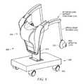
- FIG. 8shows an example portable load lifting system that comprises a cart including wheels that mounts the load lifting mechanism on a support structure that is secured to the cart, according to another disclosed embodiment.
- Disclosed embodimentsare described with reference to the attached figures, wherein like reference numerals, are used throughout the figures to designate similar or equivalent elements.
- the figuresare not drawn to scale and they are provided merely to illustrate aspects disclosed herein.
- Several disclosed aspectsare described below with reference to example applications for illustration. It should be understood that numerous specific details, relationships, and methods are set forth to provide a full understanding of the embodiments disclosed herein.
- One having ordinary skill in the relevant art, however,will readily recognize that the disclosed embodiments can be practiced without one or more of the specific details or with other methods.
- well-known structures or operationsare not shown in detail to avoid obscuring aspects disclosed herein.
- Disclosed embodimentsare not limited by the illustrated ordering of acts or events, as some acts may occur in different orders and/or concurrently with other acts or events. Furthermore, not all illustrated acts or events are required to implement a methodology in accordance with this Disclosure.
- Disclosed portable load lifting systemscomprise a movable support structure and a load lifting mechanism secured to the movable support structure comprising a winch including a motor driven reel mechanism for reeling first and second lifting straps or cables that are secured to first and second end effectors.
- First and second handlesare attached to an outside surface of the first and second end effectors, where the lifting straps or cables when driven by the winch lift a load contacted by the first and second end effectors.
- the portable load lifting systemcan comprise a load lifting assist system for aiding a human user that includes a lower extremity exoskeleton and an exoskeleton torso, or can be embodied in other disclosed embodiments to include an exoskeleton torso but not a lower extremity exoskeleton.
- Other disclosed embodimentscomprise load lifting systems that are operable without the need to be secured to a human user.
- FIG. 1is a front view perspective drawing illustrating an example portable load lifting assist system 100 for aiding a human user comprising a lower extremity exoskeleton 120 and exoskeleton torso 160 including an exoskeleton trunk 109 .
- Portable load lifting assist system 100is wearable by a person and allows its wearer to carry a load in his/her front, and aid the person when lifting an object by significantly reducing the load on the user.
- portable load lifting assist system 100can be used to help lift heavy loads while exerting minimal effort, such as in an example military application for soldiers going into combat with up to 130 pounds of combat gear.
- Lower extremity exoskeleton 120in addition to other components, includes two leg supports, 101 and 102 , which are configured to be coupled to person's lower limbs and configured to rest on the ground or other surface (e.g., a floor) during their stance phase.
- the leg supports 101 and 102in addition to other components, include thigh links 103 and 104 , and shank links 105 and 106 .
- Two knee joints, 107 and 108are configured to allow flexion and extension between the shank links 105 and 106 and the thigh links 103 and 104 of the leg supports 101 , 102 during the corresponding leg support swing phase.
- the two knee joints 107 and 108in some embodiments are configured to resist flexion between the shank links 105 and 106 and the thigh links 103 and 104 of the leg supports 101 , 102 during the corresponding leg support stance phase.
- Exoskeleton torso 160comprises an exoskeleton trunk 109 .
- Exoskeleton trunk 109comprises an upper body interface device 150 .
- Exoskeleton trunk 109is configurable to be coupled to the person's upper body through the upper body interface device 150 .
- a person's upper bodyrefers to any location generally above the thighs including the buttocks of the person.
- Examples of upper body interface devices 150comprise an element or combination of elements including, without limitation, vests, belts, straps, shoulder straps, chest straps, body cast, harness, and waist belts.
- Exoskeleton trunk 109is rotatably connectable to leg supports 101 and 102 at hip flexion-extension joints 125 and 126 , allowing for the hip flexion and extension rotations of leg supports 101 and 102 about hip flexion-extension axes 151 and 152 respectively.
- Leg supports 101 and 102are configurable to be coupled to person's lower limbs through lower limb interface straps, with the lower right interface strap 135 shown in FIG. 1 (left lower limb interface strap not shown in FIG. 1 for clarity).
- each lower limb interface strapis coupled to thigh links 103 and 104 .
- lower limb interface strapsare coupled to shank links 105 and 106 .
- lower limb interface strapsare coupled to both the shank links and thigh links.
- Each lower limb interface strapcan comprise an element or combination of elements including, without limitation, straps, bars, c-shaped brackets, body cast, and elastomers.
- a personis coupled to (or wears) load lifting assist system 100 including exoskeleton torso 160 through upper body interface device 150 (a simple belt 150 ( a ) and shoulder straps 150 ( b ) shown in FIG. 1 ) and lower extremity exoskeleton 120 by coupling to two leg supports 101 and 102 through lower limb interface straps 135 and 136 .
- lower extremity exoskeleton 120may include two hip torque generators 145 and 146 which are configured to create torques between exoskeleton trunk 109 and leg supports 101 and 102 .
- the exoskeleton torso 160 shown in FIG. 1also includes a load lifting mechanism 221 .
- the load lifting mechanism 221 in FIG. 1has within it a winch 229 (see FIG. 3 ) which includes a reel mechanism which can reel in straps or lifting cables 222 that in one particular embodiment are nylon straps in order to lift a load connected to or contacted by end effectors 223 .
- Disclosed portable load lifting systemsinclude a power source (not shown) that can comprise a battery source, or other power sources such as fuel cell-based power sources.
- Disclosed portable load lifting assist systemssuch as portable load lifting assist system 100 shown in FIG. 1 are also easy for a user to put on.
- the portable load lifting assist system 100can arrive folded in a small package, so that soldiers or other users simply stretch out a leg and step into foot beds underneath the boot. Straps can then wrap around the thighs, waist and shoulders of the soldier or other user.
- FIG. 2shows an example exoskeleton torso 160 including the exoskeleton trunk 109 with a load lifting mechanism 221 connected to it, according to a disclosed embodiment.
- end effector 223is shown as a simple paddle on which a high friction material is mounted on the side opposite handle 224 .
- the high friction materialis used to help grip the sides of boxes and box like objects.
- One particular example of an example high friction materialis “GECKO SKIN.”
- end effector 223may generally be any item used to lift a load and may contain a force sensor 251 in the handle 224 in order to measure the load force which the human user is putting on the handle.
- Item 225is a lifting bar which (among other things) acts as a guide for cable 222 .
- the load lifting mechanism 221(including the internal winch, straps 222 , end effectors 223 , and handles 224 ) can be a mechanism sometimes referred to as a “human power amplifier.”
- a human power amplifierAn example of such a “human power amplifier” is disclosed in U.S. Pat. No. 6,886,812 to Kazerooni.
- the load lifting mechanism 221can also include a movable counter weight 226 which may be rotated about counter weight rotation axis 227 (see FIG. 3 ) by a counterweight actuator 228 (see FIG. 4 ).
- a counterweight actuator 228see FIG. 4 .
- One advantageous aspect of this featureis to make the mass of the counterweight 228 include the mass of the winch 229 (including its motor, indicated by the “M” in FIG. 3 ). This can be done by routing the lifting strap or cable 222 through the path shown in FIG. 3 .
- the strap or cable 222passes over a pulley 236 which is concentric with the counter weight rotation axis 227 and therefore the motion of the counterweight 228 has very little affect on the length (or load) of the lifting strap or cable 222 .
- the motorcan comprise a hydraulic motor.
- Hydraulic motor-based architecturescan be highly energy efficient to help support battery powered operation of disclosed systems including the portable load lifting assist system 100 shown in FIG. 1 .
- the load lifting mechanism 221In operation of the load lifting mechanism 221 , when loads in front of the user (on the end effectors 223 ) are high, the counterweight 226 is moved farther aft of the user in order to balance the load (at least partially) about the hip flexion-extension axes 151 and 152 . This is shown occurring in FIG. 4 .
- a controller 411such as comprising a microprocessor (or microcomputer) 412 coupled to a force sensor 413 shown in FIG. 4 which measures the force being applied by load lifting mechanism 221 to the lifting strap or cable 222 .
- the controller 411can then send a control signal that triggers movement of the movable counter weight 226 to a position appropriate to balance the moment created about hip flexion-extension axes 151 and 152 by the counter weight 226 with the moment created by the down force on the cables 222 due to the load in front of the user.
- a control signalthat triggers movement of the movable counter weight 226 to a position appropriate to balance the moment created about hip flexion-extension axes 151 and 152 by the counter weight 226 with the moment created by the down force on the cables 222 due to the load in front of the user.
- hip torque generators 145 and 146may be greatly reduced or even eliminated because the wearer of the exoskeleton torso 160 can provide the small amount of remaining torque needed to the keep the exoskeleton trunk 109 upright.
- a movable counter weight 226which translated linearly or swung on a linkage type mechanism in a manner that would not be a rotation about a counter weight rotation axis 227 . Any mechanism which will move the counterweight farther behind (or closer to) the hip flexion-extension axes 151 and 152 will generally be able to produce the desired effect.
- FIG. 3depicts a partial cross section depiction of an exemplary load lifting bar mechanism 230 associated with exoskeleton torso 160 , according to a disclosed embodiment.
- the load lifting bar mechanism 230includes a lifting bar 225 , lifting bar guide 231 , and cam plate 232 .
- the lifting bar 225slides over the lifting bar guide 231 in a telescopic fashion.
- the position of lifting bar 225 along the lifting bar guide 231is determined by the cam roller 233 which is mounted on the lifting bar 225 and moves in a slot 234 on cam plate 232 .
- the lifting bar guide 231pivots on the pivot 235 .
- Pulley 236is a pulley over which the strap or cable 222 runs. When enough of the strap or cable 222 is retrieved such that the end effectors 223 are approaching the ends of the lifting bar 225 , the lifting bar 225 starts to move upward and outward as the cam roller 233 moves upward in the slot 234 on cam plate 232 .
- FIG. 6shows a close up view of the rear end of the lifting bar guide 231 .
- the lifting strap 222is actually comprised of two parts, the main lifting strap 237 and the lifting strap loop 238 .
- the main strap 237 and the strap loop 238are attached (e.g., sewn or bonded) together in the regions 239 and 240 .
- the pulley 236comprises a body 241 and flanges 242 .
- the lifting strap loop 238will wrap around the pulley body 241 and begin pulling downward on the pulley body. This will cause the lifting bar guide 231 to pivot on the pivot 235 which will cause the lifting bar 225 to move upward and outward.
- the strap loop 238encounters the pulley body 241 at a point where there is still strap available between the end of the lifting bar 225 and the end effector 223 . If there were no strap available, the lifting bar 225 could not extend along the lifting bar guide 231 because it would be constrained by the strap or cable 222 .
- load lifting bar mechanism 230which solely by pulling on a strap or a cable, the lifting bars will move upward and outward when the strap or cable is near the end of its travel. This allows the wearer of exoskeleton torso 160 to lift loads up to much higher heights than retracted lifting bars would allow.
- the portable load lifting assist systemis not attached to a lower extremity exoskeleton 120 as described above relative to FIGS. 1-6 .
- the portable load lifting assist systemcan comprise only exoskeleton torso 160 which can be worn by a user analogous to a backpack.
- FIG. 7shows a depiction of an exemplary portable load lifting assist system 700 that includes straps 710 that allows the portable load lifting assist system 700 comprising exoskeleton trunk 109 to be worn by a user like a backpack.
- the movable counter weight 226is identified in FIG. 7 by its function “counter-balance mechanism”.
- the portable load lifting systemcan be attached to a mobile unit.
- FIG. 8shows an exemplary portable load lifting system 800 that comprises a cart 820 including wheels 825 that mounts an example load lifting system 840 on a movable support structure 810 (e.g., bolted or welded) that is secured to the cart 820 .
- the movable support structure 810has mobility via the cart 820 .
- Portable load lifting system 800 as well as disclosed portable load lifting assist systemscan be used to support a variety of applications, including military, industrial and medical applications. assist soldiers during combat.
- disclosed portable load lifting systemsinclude simplicity of actuation and flexibility to relocate to alternate work or other areas. Unlike a fully articulated arm, disclosed embodiments can use minimal sensing and actuation capability. This reduces the cost and power requirements and improves the reliability of the design as compared to an actuated arm. Also, unlike known fixed load attachment, load lifting systems disclosed herein allow for the raising and lowering of the load. For example, a user such as a soldier using a disclosed portable lifting assist system can raise a load above his or her shoulders, as well as lower the load to the ground.
- portable load lifting systems disclosed hereinhave significantly enhanced flexibility in its usage. Because disclosed load lifting systems are not physically restrained to a work area, a user can operate the load lifting system inside a warehouse one minute, then head directly outside and continue to operate the load lifting system. This provides much greater utility to the user at lower cost and with lower power consumption.
Landscapes
- Engineering & Computer Science (AREA)
- Mechanical Engineering (AREA)
- Robotics (AREA)
- Manipulator (AREA)
Abstract
Description
Claims (21)
Priority Applications (1)
| Application Number | Priority Date | Filing Date | Title |
|---|---|---|---|
| US13/084,265US9333644B2 (en) | 2010-04-09 | 2011-04-11 | Portable load lifting system |
Applications Claiming Priority (2)
| Application Number | Priority Date | Filing Date | Title |
|---|---|---|---|
| US32268410P | 2010-04-09 | 2010-04-09 | |
| US13/084,265US9333644B2 (en) | 2010-04-09 | 2011-04-11 | Portable load lifting system |
Publications (2)
| Publication Number | Publication Date |
|---|---|
| US20110264014A1 US20110264014A1 (en) | 2011-10-27 |
| US9333644B2true US9333644B2 (en) | 2016-05-10 |
Family
ID=44763313
Family Applications (1)
| Application Number | Title | Priority Date | Filing Date |
|---|---|---|---|
| US13/084,265Expired - Fee RelatedUS9333644B2 (en) | 2010-04-09 | 2011-04-11 | Portable load lifting system |
Country Status (5)
| Country | Link |
|---|---|
| US (1) | US9333644B2 (en) |
| EP (1) | EP2556010B1 (en) |
| JP (1) | JP6008836B2 (en) |
| CN (1) | CN103038152A (en) |
| WO (1) | WO2011127471A1 (en) |
Cited By (14)
| Publication number | Priority date | Publication date | Assignee | Title |
|---|---|---|---|---|
| US20160158593A1 (en)* | 2014-12-04 | 2016-06-09 | Florida Institute for Human and Machine Cognition | Exoskeleton-Based Exercise and Training Device |
| US20160199685A1 (en)* | 2009-06-19 | 2016-07-14 | Tau Orthopedics, Llc | Toning garment with modular resistance unit docking platforms |
| US20160339583A1 (en)* | 2015-05-18 | 2016-11-24 | The Regents Of The University Of California | Method and apparatus for human arm supporting exoskeleton |
| US20180200134A1 (en)* | 2017-11-13 | 2018-07-19 | Free Bionics Taiwan Inc. | Shoe assembly for a walking assist device |
| US10124205B2 (en) | 2016-03-14 | 2018-11-13 | Tau Orthopedics, Llc | Toning garment with modular resistance unit docking platforms |
| US10124484B1 (en) | 2015-12-08 | 2018-11-13 | Lockheed Martin Corporation | Load-bearing powered exoskeleton using electromyographic control |
| US10518404B2 (en) | 2015-07-17 | 2019-12-31 | Lockheed Martin Corporation | Variable force exoskeleton hip joint |
| US10548800B1 (en) | 2015-06-18 | 2020-02-04 | Lockheed Martin Corporation | Exoskeleton pelvic link having hip joint and inguinal joint |
| US10765911B1 (en) | 2019-03-01 | 2020-09-08 | Dustin Hamoy | Core exercise assembly |
| US10912346B1 (en) | 2015-11-24 | 2021-02-09 | Lockheed Martin Corporation | Exoskeleton boot and lower link |
| US20210361516A1 (en)* | 2020-05-25 | 2021-11-25 | Jtekt Corporation | Assist device |
| US11207014B2 (en) | 2017-08-30 | 2021-12-28 | Lockheed Martin Corporation | Automatic sensor selection |
| US20220151858A1 (en)* | 2020-11-16 | 2022-05-19 | KYOCERA AVX Components Corporation | Exoskeleton Powered Using an Ultracapacitor |
| US12029699B2 (en) | 2020-03-19 | 2024-07-09 | Suitx, Inc. | Remote center shoulder joint for shoulder supporting exoskeleton |
Families Citing this family (96)
| Publication number | Priority date | Publication date | Assignee | Title |
|---|---|---|---|---|
| CN102548514B (en)* | 2009-09-28 | 2014-07-30 | 学校法人东京理科大学 | lumbar assist device |
| FR2978690A1 (en)* | 2011-08-02 | 2013-02-08 | Pierre Andre Davezac | Electronic exoskeleton for lifting and carrying loads in e.g. military, has hook descended on ground in which load rests and secured to worker when worker is entitled by preserving arms to stabilize before load is suspended to height |
| JP6169837B2 (en)* | 2011-11-02 | 2017-07-26 | パナソニック株式会社 | Lower limb movement support device |
| US20130145530A1 (en)* | 2011-12-09 | 2013-06-13 | Manu Mitra | Iron man suit |
| US9095981B2 (en) | 2012-01-11 | 2015-08-04 | Garrett W. Brown | Load and torque resistant caliper exoskeleton |
| CN102805915A (en)* | 2012-08-06 | 2012-12-05 | 陈建瑜 | Intelligent power assisting system |
| EP2931204B1 (en)* | 2012-12-11 | 2019-04-03 | Ekso Bionics, Inc. | Reconfigurable exoskeleton |
| CN103006416B (en)* | 2013-01-04 | 2014-08-20 | 哈尔滨工程大学 | Mechanical lower-limb rehabilitation robot walker device |
| AU2014240405B2 (en)* | 2013-03-14 | 2018-06-14 | Ekso Bionics, Inc. | Non-anthropomorphic hip joint locations for exoskeletons |
| CN103284819B (en)* | 2013-04-24 | 2015-08-19 | 西南交通大学 | A kind of assistance type ectoskeleton is with front lifting formula adjustable back negative system |
| JP6284318B2 (en)* | 2013-08-30 | 2018-02-28 | 三菱重工業株式会社 | Power assist suit |
| JP6284319B2 (en)* | 2013-08-30 | 2018-02-28 | 三菱重工業株式会社 | Power assist suit |
| KR101500525B1 (en)* | 2013-10-16 | 2015-03-09 | 대우조선해양 주식회사 | folding working unit for wearable robot |
| ITFR20130013A1 (en)* | 2013-11-25 | 2015-05-26 | Marco Ceccarelli | EXOSCHELETER DEVICE FOR ASSISTANCE TO HUMAN LOCOMOTION. |
| JP5902664B2 (en)* | 2013-12-25 | 2016-04-13 | ファナック株式会社 | Human cooperative industrial robot with protective member |
| FR3016821B1 (en)* | 2014-01-29 | 2019-08-02 | Robotiques 3 Dimensions | EXOSQUELETTE WITH FRONT PORT AND METHOD OF USING SUCH AN EXOSQUELET. |
| JP6153881B2 (en)* | 2014-03-20 | 2017-06-28 | 株式会社クボタ | Assist suit |
| JP6148192B2 (en)* | 2014-03-20 | 2017-06-14 | 株式会社クボタ | Assist suit |
| JP6184355B2 (en)* | 2014-03-20 | 2017-08-23 | 株式会社クボタ | Assist suit |
| EP3119369A4 (en)* | 2014-03-21 | 2017-11-29 | Ekso Bionics, Inc. | Ambulatory exoskeleton and method of relocating exoskeleton |
| US9604369B2 (en)* | 2014-06-04 | 2017-03-28 | Ekso Bionics, Inc. | Exoskeleton and method of increasing the flexibility of an exoskeleton hip joint |
| US9492300B2 (en) | 2014-06-18 | 2016-11-15 | Mawashi Protective Clothing Inc. | Exoskeleton and method of using the same |
| US10561568B1 (en)* | 2014-06-19 | 2020-02-18 | Lockheed Martin Corporation | Exoskeleton system providing for a load transfer when a user is standing and kneeling |
| CN104013514B (en)* | 2014-06-19 | 2017-02-15 | 中国北方车辆研究所 | Hydraulically-driven wearable human body assisting walking robot |
| KR102250235B1 (en)* | 2014-07-17 | 2021-05-10 | 삼성전자주식회사 | A fixing module and a motion assist apparatus comprising thereof |
| WO2016113954A1 (en)* | 2015-01-14 | 2016-07-21 | 株式会社クボタ | Assistive suit |
| JP6548394B2 (en)* | 2015-01-14 | 2019-07-24 | 株式会社クボタ | Assist suit |
| JP2016130160A (en)* | 2015-01-14 | 2016-07-21 | 株式会社クボタ | Assist suit |
| JP6504823B2 (en)* | 2015-01-14 | 2019-04-24 | 株式会社クボタ | Assist suit |
| JP2016129917A (en)* | 2015-01-14 | 2016-07-21 | 株式会社クボタ | Assist suit |
| CN104669249B (en)* | 2015-02-01 | 2016-05-04 | 襄阳新火炬科技有限公司 | One hydraulic drive type robot |
| EP3064822B1 (en)* | 2015-03-02 | 2018-05-30 | Easyrig AB | Camera rig |
| US10390973B2 (en) | 2015-05-11 | 2019-08-27 | The Hong Kong Polytechnic University | Interactive exoskeleton robotic knee system |
| US10195736B2 (en) | 2015-07-17 | 2019-02-05 | Lockheed Martin Corporation | Variable force exoskeleton hip joint |
| CN105105896B (en)* | 2015-09-17 | 2016-11-30 | 武汉大学 | For the adjusting means that wearable lower limb exoskeleton robot is fixing with human body waist |
| WO2017075462A1 (en) | 2015-10-30 | 2017-05-04 | Ekso Bionics, Inc. | Human exoskeleton devices for heavy tool support and use |
| JP6643874B2 (en)* | 2015-11-20 | 2020-02-12 | 株式会社クボタ | Assist suit |
| WO2017086378A1 (en) | 2015-11-20 | 2017-05-26 | 株式会社クボタ | Assistance suit |
| JP6541553B2 (en)* | 2015-11-20 | 2019-07-10 | 株式会社クボタ | Assist suit |
| JP6754563B2 (en)* | 2015-11-20 | 2020-09-16 | 株式会社クボタ | Assist suit |
| JP6541552B2 (en)* | 2015-11-20 | 2019-07-10 | 株式会社クボタ | Assist suit |
| US20190344432A1 (en) | 2015-12-24 | 2019-11-14 | Safran Electronics & Defense | Modular exoskeleton structure that provides force assistance to the user |
| FR3046051B1 (en)* | 2015-12-24 | 2020-11-13 | Sagem Defense Securite | BACK MODULE FOR AN EXOSKELETON STRUCTURE |
| FR3046038B1 (en)* | 2015-12-24 | 2017-12-22 | Sagem Defense Securite | BACKPACK SUPPORT MODULE FOR A MODULAR STRUCTURE OF EXOSQUELET |
| EP3403775A4 (en)* | 2016-01-15 | 2020-01-22 | Kubota Corporation | AUXILIARY DEVICE |
| JP6671179B2 (en)* | 2016-01-15 | 2020-03-25 | 株式会社クボタ | Assist equipment |
| JP6671180B2 (en)* | 2016-01-15 | 2020-03-25 | 株式会社クボタ | Assist equipment |
| CN105853145B (en)* | 2016-04-12 | 2020-10-09 | 合肥工业大学 | Leg mechanical mechanism capable of realizing walking function |
| US11209121B2 (en)* | 2016-04-26 | 2021-12-28 | The Boeing Company | Lifting support device and method of controlling operation |
| JP6566912B2 (en)* | 2016-06-28 | 2019-08-28 | 株式会社クボタ | Assist suit |
| JP2018002333A (en)* | 2016-06-28 | 2018-01-11 | 株式会社クボタ | Assist suit |
| CN106346452B (en)* | 2016-11-02 | 2017-06-23 | 广州初曲科技有限公司 | A kind of air-electricity linkage formula ectoskeleton chain drive that the small of the back strength auxiliary is provided |
| EP3560664A4 (en)* | 2016-12-22 | 2020-09-30 | Kubota Corporation | Assistance tool |
| FR3061445B1 (en)* | 2016-12-29 | 2019-05-24 | Safran Electronics & Defense | BONDING DEVICE FOR EXOSKELET STRUCTURE FACILITATING THE LOADING OF LOADS DURING THE MARKET OR THE RACE |
| CN106821689B (en)* | 2017-01-19 | 2023-07-04 | 武汉云云天下信息科技有限公司 | Wearable human exoskeleton robot |
| CN106628806A (en)* | 2017-02-28 | 2017-05-10 | 深圳龙海特机器人科技有限公司 | Double-open wearing-type auxiliary carrying device |
| JP2018149624A (en)* | 2017-03-13 | 2018-09-27 | パナソニック株式会社 | Operation support device |
| JP6783171B2 (en)* | 2017-03-23 | 2020-11-11 | 株式会社クボタ | Assist equipment |
| JP6742274B2 (en)* | 2017-05-18 | 2020-08-19 | 株式会社クボタ | Assist suit |
| JP2017149585A (en)* | 2017-05-30 | 2017-08-31 | 株式会社クボタ | Assist suit |
| CN110740967A (en)* | 2017-06-29 | 2020-01-31 | 株式会社久保田 | Hand and assisting tool for holding goods |
| SG11201912537PA (en)* | 2017-09-07 | 2020-01-30 | Bo Yuan | Exoskeleton |
| US11000439B2 (en)* | 2017-09-28 | 2021-05-11 | Ossur Iceland Ehf | Body interface |
| CN107569367B (en)* | 2017-10-18 | 2021-09-17 | 房倩玉 | Lower limb rehabilitation training device |
| DE102018103300A1 (en)* | 2018-02-14 | 2019-08-14 | Noonee Ag | Portable sitting position help device |
| CN109081038A (en)* | 2018-09-18 | 2018-12-25 | 上海工程技术大学 | A kind of wearable work-saving device |
| USD947388S1 (en)* | 2018-12-10 | 2022-03-29 | Jtekt Corporation | Motion assisting device |
| JP6758364B2 (en)* | 2018-12-25 | 2020-09-23 | 株式会社クボタ | Assist suit |
| JP6749443B2 (en)* | 2019-03-07 | 2020-09-02 | 株式会社クボタ | Assist suit |
| JP6756002B2 (en)* | 2019-05-07 | 2020-09-16 | 株式会社クボタ | Assist suit |
| JP7427321B2 (en)* | 2019-06-18 | 2024-02-05 | 株式会社キトー | Power control device and power control method |
| CN110575366B (en)* | 2019-09-19 | 2022-01-18 | 哈尔滨工业大学 | Active and passive combined lower limb assistance exoskeleton robot |
| KR102422726B1 (en)* | 2019-11-27 | 2022-07-20 | 피씨오낙(주) | transporter for goods and carrier for child |
| CN111285280B (en)* | 2020-02-02 | 2021-08-31 | 广西电网有限责任公司北海供电局 | Backpack electric power high altitude construction transmission device |
| RU198903U1 (en)* | 2020-02-26 | 2020-07-31 | ООО "Экзомед" | Exoskeleton |
| RU202647U1 (en)* | 2020-06-11 | 2021-03-01 | Общество с ограниченной ответственностью "Экзомед" | Device for facilitating the movement of goods |
| EP4015156A1 (en)* | 2020-12-15 | 2022-06-22 | Auxivo AG | Load supporting device and its use |
| CN112549002A (en)* | 2020-12-22 | 2021-03-26 | 山东中科先进技术研究院有限公司 | Upper limb exoskeleton power assisting device and control method |
| CN112936232B (en)* | 2021-04-08 | 2022-10-28 | 中国科学技术大学 | Hip joint exoskeleton robot system assisting diving |
| EP4079460A1 (en)* | 2021-04-22 | 2022-10-26 | Hilti Aktiengesellschaft | System, kit and electronic module for balancing a weight of an object |
| CN112975918B (en)* | 2021-04-27 | 2025-08-19 | 山东中科先进技术研究院有限公司 | Wearable rope-driven upper limb booster device |
| FR3125453A1 (en)* | 2021-07-26 | 2023-01-27 | Hublex | Assistance device for manual carrying of loads |
| CN113894771A (en)* | 2021-08-27 | 2022-01-07 | 北京机械设备研究所 | Active pull-belt type upper limb assistance exoskeleton |
| WO2023086541A1 (en)* | 2021-11-12 | 2023-05-19 | Hamon Richard A | Ladder hoist and cart system |
| US12252936B2 (en)* | 2021-12-29 | 2025-03-18 | Mulepro Industries, Llc | Building ladder hoist |
| US12096841B2 (en) | 2021-11-12 | 2024-09-24 | MulePro Industries LLC | Tank carrier with backpack straps and dolly |
| DE102022100204A1 (en)* | 2022-01-05 | 2023-07-06 | J.Schmalz Gmbh | Auxiliary device that can be pulled on with an articulated connection to the upper body connection |
| DE102022100202A1 (en)* | 2022-01-05 | 2023-07-06 | J.Schmalz Gmbh | Pullable auxiliary device |
| DE102022100203A1 (en)* | 2022-01-05 | 2023-07-06 | J.Schmalz Gmbh | Auxiliary device that can be pulled on with an articulated connection to the lower body connection |
| CN114643571B (en)* | 2022-03-14 | 2023-07-21 | 南京赤研科技有限公司 | Full-freedom-degree upper limb exoskeleton device |
| CN114932536B (en)* | 2022-05-31 | 2023-07-28 | 山东大学 | Walkable Active Mechanism |
| CN114833804B (en)* | 2022-06-13 | 2024-09-13 | 山东瑞曼智能装备有限公司 | Active power assisting device and method suitable for multiple scenes |
| CN115302493B (en)* | 2022-07-25 | 2024-10-22 | 重庆理工大学 | Friction damping driver and exoskeleton |
| WO2024039310A1 (en)* | 2022-08-16 | 2024-02-22 | Interact Medikal Teknolojileri Anonim Sirketi | Adjustable passive exoskeleton |
| CN116350476B (en)* | 2023-04-13 | 2025-04-18 | 沈阳航空航天大学 | A lower limb auxiliary mobility rehabilitation device |
| CN119427316A (en)* | 2024-10-29 | 2025-02-14 | 杭州智元研究院有限公司 | Active lower limb carrying exoskeleton device |
Citations (51)
| Publication number | Priority date | Publication date | Assignee | Title |
|---|---|---|---|---|
| US2010482A (en)* | 1934-05-26 | 1935-08-06 | Florence M Henn | Walking motion |
| US3964182A (en)* | 1973-10-31 | 1976-06-22 | Pomeret Jean Claude | Mechanical shovel |
| US4258556A (en) | 1977-11-10 | 1981-03-31 | U.S. Philips Corporation | Torsion spring clutch |
| US5016869A (en)* | 1989-07-05 | 1991-05-21 | Applied Motion | Human bipedal locomotion device |
| US5020790A (en)* | 1990-10-23 | 1991-06-04 | Board Of Supervisors Of Louisiana State University And Agricultural And Mechanical College | Powered gait orthosis |
| JPH03105191U (en) | 1990-02-15 | 1991-10-31 | ||
| JP3024978U (en) | 1995-10-13 | 1996-06-07 | 吉村 敏正 | Backpack-type luggage lifting device |
| US5865426A (en)* | 1996-03-27 | 1999-02-02 | Kazerooni; Homayoon | Human power amplifier for vertical maneuvers |
| US5993404A (en) | 1998-06-16 | 1999-11-30 | Mc Niel; Frank T. | Walking brace |
| JP2003104682A (en) | 2001-09-30 | 2003-04-09 | Kosho Unyu Kk | Load moving auxiliary tool |
| US20030073552A1 (en) | 2001-10-11 | 2003-04-17 | Knight Michael W. | Biosensory ergonomic chair |
| US20030109817A1 (en) | 2001-12-11 | 2003-06-12 | Shimon Berl | Supplementary knee support brace |
| US20030115954A1 (en) | 2001-12-07 | 2003-06-26 | Vladimir Zemlyakov | Upper extremity exoskeleton structure and method |
| US6886812B2 (en) | 1999-05-13 | 2005-05-03 | Hamayoon Kazerooni | Human power amplifier for lifting load with slack prevention apparatus |
| US20050137717A1 (en) | 2003-12-18 | 2005-06-23 | Finn Gramnas | Prosthetic foot with rocker member |
| US6913583B2 (en) | 2003-06-19 | 2005-07-05 | Creations By B J H, Llc | Orthopedic device allows kneeling without contacting knee |
| US20060064047A1 (en)* | 2004-09-21 | 2006-03-23 | Honda Motor Co., Ltd. | Walking assistance system |
| US20060260620A1 (en) | 2005-01-18 | 2006-11-23 | The Regents Of University Of California | Lower extremity exoskeleton |
| US7153242B2 (en) | 2001-05-24 | 2006-12-26 | Amit Goffer | Gait-locomotor apparatus |
| US7163518B1 (en) | 2003-10-20 | 2007-01-16 | Rgpartnership Llp | Walking leg support |
| US20070056592A1 (en) | 2005-04-13 | 2007-03-15 | The Regents Of University Of California | Semi-powered lower extremity exoskeleton |
| US20070123997A1 (en) | 2005-03-31 | 2007-05-31 | Massachusetts Institute Of Technology | Exoskeletons for running and walking |
| US20070233279A1 (en) | 2006-03-09 | 2007-10-04 | The Regents Of The University Of California | Power generating leg |
| JP2009011818A (en) | 2007-06-07 | 2009-01-22 | Tokyo Univ Of Science | Lumbar assist device |
| US7571839B2 (en) | 2004-05-19 | 2009-08-11 | Hrl Laboratories, Llc | Passive exoskeleton |
| US20090210093A1 (en)* | 2006-07-17 | 2009-08-20 | Jacobsen Stephen C | Contact displacement actuator system |
| US20090292369A1 (en) | 2008-05-20 | 2009-11-26 | Berkeley Bionics | Device and Method for Decreasing Energy Consumption of a Person by Use of a Lower Extremity Exoskeleton |
| US7628766B1 (en)* | 2003-10-29 | 2009-12-08 | The Regents Of The University Of California | Lower extremity enhancer |
| US20100094185A1 (en) | 2008-05-20 | 2010-04-15 | University Of California At Berkeley | Device and Method for Decreasing Oxygen Consumption of a Person During Steady Walking by Use of a Load-Carrying Exoskeleton |
| US20110105966A1 (en) | 2008-07-23 | 2011-05-05 | Berkeley Bionics | Exoskeleton and Method for Controlling a Swing Leg of the Exoskeleton |
| US20110166489A1 (en) | 2008-09-24 | 2011-07-07 | Berkeley Bionics | Hip and Knee Actuation Systems for Lower Limb Orthotic Devices |
| US20110214524A1 (en)* | 2008-08-28 | 2011-09-08 | Raytheon Company | Biomimetic Mechanical Joint |
| US20110266323A1 (en) | 2008-12-18 | 2011-11-03 | The Regents Of The University Of California | Wearable Material Handling System |
| US8171570B2 (en) | 2007-04-23 | 2012-05-08 | Golden Crab S.L. | Exoskeleton |
| US20120172770A1 (en) | 2009-07-01 | 2012-07-05 | Faisal Almesfer | Control System for a Mobility Aid |
| US8231688B2 (en) | 2008-06-16 | 2012-07-31 | Berkeley Bionics | Semi-actuated transfemoral prosthetic knee |
| US8257291B2 (en) | 2008-06-11 | 2012-09-04 | The Regents Of The University Of California | External walking assist device for those with lower leg injuries |
| US20120283845A1 (en) | 2011-03-11 | 2012-11-08 | Herr Hugh M | Biomimetic joint actuators |
| WO2012154580A1 (en) | 2011-05-06 | 2012-11-15 | Equipois Inc. | Exoskeleton arm interface |
| US20130023800A1 (en) | 2010-04-07 | 2013-01-24 | Bedard Stephane | Load distribution device for human joints |
| US8394038B2 (en) | 2008-11-06 | 2013-03-12 | Honda Motor Co., Ltd. | Walking assistance device |
| US20130150980A1 (en) | 2008-06-16 | 2013-06-13 | The Regents Of The University Of California | Powered Lower Extremity Orthotic and Method of Operation |
| US20130197408A1 (en) | 2010-09-27 | 2013-08-01 | Vanderbilt University | Movement assistance device |
| US20130231595A1 (en) | 2010-09-17 | 2013-09-05 | The Regents Of The University Of California | Human Machine Interface for Human Exoskeleton |
| US20130237884A1 (en) | 2010-10-06 | 2013-09-12 | The Regents Of The University Of California | Human Machine Interfaces for Lower Extremity Orthotics |
| US20130296746A1 (en) | 2012-02-24 | 2013-11-07 | Massachusetts Institute Of Technology | Elastic Element Exoskeleton and Method of Using Same |
| US20130303950A1 (en) | 2010-04-09 | 2013-11-14 | Ekso Bionics | Exoskeleton Load Handling System and Method of Use |
| US20140046234A1 (en) | 2012-08-09 | 2014-02-13 | Egas Jose-Joaquim DeSousa | Dynamic Load Bearing Shock Absorbing Exoskeletal Knee Brace |
| US8672865B2 (en) | 2008-11-26 | 2014-03-18 | Toad Medical Corporation | Weight-bearing lower extremity brace |
| US8702632B2 (en) | 2009-01-12 | 2014-04-22 | Iucf-Hyu (Industry-University Cooperation Foundation Hanyang University) | Wearable robot for assisting muscular strength of lower extremity |
| US20140200491A1 (en) | 2013-01-16 | 2014-07-17 | Ekso Bionics, Inc. | Fail-Safe System for Exoskeleton Joints |
- 2011
- 2011-04-11CNCN2011800283325Apatent/CN103038152A/enactivePending
- 2011-04-11WOPCT/US2011/031956patent/WO2011127471A1/enactiveApplication Filing
- 2011-04-11JPJP2013504019Apatent/JP6008836B2/ennot_activeExpired - Fee Related
- 2011-04-11EPEP11766862.4Apatent/EP2556010B1/enactiveActive
- 2011-04-11USUS13/084,265patent/US9333644B2/ennot_activeExpired - Fee Related
Patent Citations (63)
| Publication number | Priority date | Publication date | Assignee | Title |
|---|---|---|---|---|
| US2010482A (en)* | 1934-05-26 | 1935-08-06 | Florence M Henn | Walking motion |
| US3964182A (en)* | 1973-10-31 | 1976-06-22 | Pomeret Jean Claude | Mechanical shovel |
| US4258556A (en) | 1977-11-10 | 1981-03-31 | U.S. Philips Corporation | Torsion spring clutch |
| US5016869A (en)* | 1989-07-05 | 1991-05-21 | Applied Motion | Human bipedal locomotion device |
| JPH03105191U (en) | 1990-02-15 | 1991-10-31 | ||
| US5020790A (en)* | 1990-10-23 | 1991-06-04 | Board Of Supervisors Of Louisiana State University And Agricultural And Mechanical College | Powered gait orthosis |
| JP3024978U (en) | 1995-10-13 | 1996-06-07 | 吉村 敏正 | Backpack-type luggage lifting device |
| US5865426A (en)* | 1996-03-27 | 1999-02-02 | Kazerooni; Homayoon | Human power amplifier for vertical maneuvers |
| US5993404A (en) | 1998-06-16 | 1999-11-30 | Mc Niel; Frank T. | Walking brace |
| US6886812B2 (en) | 1999-05-13 | 2005-05-03 | Hamayoon Kazerooni | Human power amplifier for lifting load with slack prevention apparatus |
| US7153242B2 (en) | 2001-05-24 | 2006-12-26 | Amit Goffer | Gait-locomotor apparatus |
| JP2003104682A (en) | 2001-09-30 | 2003-04-09 | Kosho Unyu Kk | Load moving auxiliary tool |
| US20030073552A1 (en) | 2001-10-11 | 2003-04-17 | Knight Michael W. | Biosensory ergonomic chair |
| US20030115954A1 (en) | 2001-12-07 | 2003-06-26 | Vladimir Zemlyakov | Upper extremity exoskeleton structure and method |
| US20030109817A1 (en) | 2001-12-11 | 2003-06-12 | Shimon Berl | Supplementary knee support brace |
| US6913583B2 (en) | 2003-06-19 | 2005-07-05 | Creations By B J H, Llc | Orthopedic device allows kneeling without contacting knee |
| US7163518B1 (en) | 2003-10-20 | 2007-01-16 | Rgpartnership Llp | Walking leg support |
| US7628766B1 (en)* | 2003-10-29 | 2009-12-08 | The Regents Of The University Of California | Lower extremity enhancer |
| US8070700B2 (en) | 2003-10-29 | 2011-12-06 | The Regents Of The University Of California | Lower extremity enhancer |
| US20050137717A1 (en) | 2003-12-18 | 2005-06-23 | Finn Gramnas | Prosthetic foot with rocker member |
| US7571839B2 (en) | 2004-05-19 | 2009-08-11 | Hrl Laboratories, Llc | Passive exoskeleton |
| US20060064047A1 (en)* | 2004-09-21 | 2006-03-23 | Honda Motor Co., Ltd. | Walking assistance system |
| US20060260620A1 (en) | 2005-01-18 | 2006-11-23 | The Regents Of University Of California | Lower extremity exoskeleton |
| US7947004B2 (en) | 2005-01-18 | 2011-05-24 | The Regents Of The University Of California | Lower extremity exoskeleton |
| US20070123997A1 (en) | 2005-03-31 | 2007-05-31 | Massachusetts Institute Of Technology | Exoskeletons for running and walking |
| US20110040216A1 (en) | 2005-03-31 | 2011-02-17 | Massachusetts Institute Of Technology | Exoskeletons for running and walking |
| US20070056592A1 (en) | 2005-04-13 | 2007-03-15 | The Regents Of University Of California | Semi-powered lower extremity exoskeleton |
| US8057410B2 (en) | 2005-04-13 | 2011-11-15 | The Regents Of The University Of California | Semi-powered lower extremity exoskeleton |
| US7883546B2 (en) | 2006-03-09 | 2011-02-08 | The Regents Of The University Of California | Power generating leg |
| US20070233279A1 (en) | 2006-03-09 | 2007-10-04 | The Regents Of The University Of California | Power generating leg |
| US20090210093A1 (en)* | 2006-07-17 | 2009-08-20 | Jacobsen Stephen C | Contact displacement actuator system |
| US8171570B2 (en) | 2007-04-23 | 2012-05-08 | Golden Crab S.L. | Exoskeleton |
| JP2009011818A (en) | 2007-06-07 | 2009-01-22 | Tokyo Univ Of Science | Lumbar assist device |
| US20090292369A1 (en) | 2008-05-20 | 2009-11-26 | Berkeley Bionics | Device and Method for Decreasing Energy Consumption of a Person by Use of a Lower Extremity Exoskeleton |
| US20100094185A1 (en) | 2008-05-20 | 2010-04-15 | University Of California At Berkeley | Device and Method for Decreasing Oxygen Consumption of a Person During Steady Walking by Use of a Load-Carrying Exoskeleton |
| US8894592B2 (en) | 2008-05-20 | 2014-11-25 | University of California at Berkekey | Device and method for decreasing oxygen consumption of a person during steady walking by use of a load-carrying exoskeleton |
| US20130102935A1 (en) | 2008-05-20 | 2013-04-25 | Berkeley Bionics | Device and Method for Decreasing Energy Consumption of a Person by Use of a Lower Extremity Exoskeleton |
| US8945028B2 (en) | 2008-05-20 | 2015-02-03 | Ekso Bionics, Inc. | Device and method for decreasing energy consumption of a person by use of a lower extremity exoskeleton |
| US8257291B2 (en) | 2008-06-11 | 2012-09-04 | The Regents Of The University Of California | External walking assist device for those with lower leg injuries |
| US8231688B2 (en) | 2008-06-16 | 2012-07-31 | Berkeley Bionics | Semi-actuated transfemoral prosthetic knee |
| US20130150980A1 (en) | 2008-06-16 | 2013-06-13 | The Regents Of The University Of California | Powered Lower Extremity Orthotic and Method of Operation |
| US8801641B2 (en) | 2008-07-23 | 2014-08-12 | Ekso Bionics, Inc. | Exoskeleton and method for controlling a swing leg of the exoskeleton |
| US20110105966A1 (en) | 2008-07-23 | 2011-05-05 | Berkeley Bionics | Exoskeleton and Method for Controlling a Swing Leg of the Exoskeleton |
| US20110214524A1 (en)* | 2008-08-28 | 2011-09-08 | Raytheon Company | Biomimetic Mechanical Joint |
| US9011354B2 (en) | 2008-09-24 | 2015-04-21 | Ekso Bionics, Inc. | Hip and knee actuation systems for lower limb orthotic devices |
| US20110166489A1 (en) | 2008-09-24 | 2011-07-07 | Berkeley Bionics | Hip and Knee Actuation Systems for Lower Limb Orthotic Devices |
| US8394038B2 (en) | 2008-11-06 | 2013-03-12 | Honda Motor Co., Ltd. | Walking assistance device |
| US8672865B2 (en) | 2008-11-26 | 2014-03-18 | Toad Medical Corporation | Weight-bearing lower extremity brace |
| US20110266323A1 (en) | 2008-12-18 | 2011-11-03 | The Regents Of The University Of California | Wearable Material Handling System |
| US8968222B2 (en) | 2008-12-18 | 2015-03-03 | Ekso Bionics, Inc. | Wearable material handling system |
| US8702632B2 (en) | 2009-01-12 | 2014-04-22 | Iucf-Hyu (Industry-University Cooperation Foundation Hanyang University) | Wearable robot for assisting muscular strength of lower extremity |
| US20120172770A1 (en) | 2009-07-01 | 2012-07-05 | Faisal Almesfer | Control System for a Mobility Aid |
| US20130023800A1 (en) | 2010-04-07 | 2013-01-24 | Bedard Stephane | Load distribution device for human joints |
| US20130303950A1 (en) | 2010-04-09 | 2013-11-14 | Ekso Bionics | Exoskeleton Load Handling System and Method of Use |
| US20130231595A1 (en) | 2010-09-17 | 2013-09-05 | The Regents Of The University Of California | Human Machine Interface for Human Exoskeleton |
| US20130197408A1 (en) | 2010-09-27 | 2013-08-01 | Vanderbilt University | Movement assistance device |
| US20130237884A1 (en) | 2010-10-06 | 2013-09-12 | The Regents Of The University Of California | Human Machine Interfaces for Lower Extremity Orthotics |
| US20120283845A1 (en) | 2011-03-11 | 2012-11-08 | Herr Hugh M | Biomimetic joint actuators |
| US20150001269A1 (en) | 2011-05-06 | 2015-01-01 | Anthony D. Sacksteder | Exoskeleton arm interface |
| WO2012154580A1 (en) | 2011-05-06 | 2012-11-15 | Equipois Inc. | Exoskeleton arm interface |
| US20130296746A1 (en) | 2012-02-24 | 2013-11-07 | Massachusetts Institute Of Technology | Elastic Element Exoskeleton and Method of Using Same |
| US20140046234A1 (en) | 2012-08-09 | 2014-02-13 | Egas Jose-Joaquim DeSousa | Dynamic Load Bearing Shock Absorbing Exoskeletal Knee Brace |
| US20140200491A1 (en) | 2013-01-16 | 2014-07-17 | Ekso Bionics, Inc. | Fail-Safe System for Exoskeleton Joints |
Non-Patent Citations (6)
| Title |
|---|
| Extended European Search Report for European Patent Application No. 11766862.4 mailed May 27, 2014, 4 pages. |
| International Preliminary Report on Patentability for PCT/US2011/031956, issued Oct. 9, 2012, 6 pages. |
| International Search Report for PCT/US2011/031956, mailed Jun. 21, 2011, 2 pages. |
| Notice of Reasons for Refusal for Japanese Patent Application No. 2013-504019, mailed Dec. 22, 2015, 6 pages. |
| Notice of Reasons for Refusal for Japanese Patent Application No. 2013-504019, mailed Feb. 24, 2015, 6 pages. |
| Whitwam, Ryan, et al., "Banks now have money-grabbing robotic exoskeletons that are probably helpful for robbing banks," PCMag Digital Group, May 9, 2015, Ziff Davis, LLC, www.geek.com/?s=japanese+banks+now+have+money+grabbing&x=0&y=0, 4 pages. |
Cited By (21)
| Publication number | Priority date | Publication date | Assignee | Title |
|---|---|---|---|---|
| US20160199685A1 (en)* | 2009-06-19 | 2016-07-14 | Tau Orthopedics, Llc | Toning garment with modular resistance unit docking platforms |
| US9656117B2 (en)* | 2009-06-19 | 2017-05-23 | Tau Orthopedics, Llc | Wearable resistance garment with power measurement |
| US10646742B2 (en) | 2009-06-19 | 2020-05-12 | Tau Orthopedics, Inc. | Toning garment with modular resistance unit docking platforms |
| US20160158593A1 (en)* | 2014-12-04 | 2016-06-09 | Florida Institute for Human and Machine Cognition | Exoskeleton-Based Exercise and Training Device |
| US20160339583A1 (en)* | 2015-05-18 | 2016-11-24 | The Regents Of The University Of California | Method and apparatus for human arm supporting exoskeleton |
| US9889554B2 (en)* | 2015-05-18 | 2018-02-13 | The Regents Of The University Of California | Apparatus for human arm supporting exoskeleton |
| US10071477B2 (en)* | 2015-05-18 | 2018-09-11 | The Regents Of The University Of California | Apparatus for human arm supporting exoskeleton |
| US10369690B2 (en)* | 2015-05-18 | 2019-08-06 | The Regents Of The University Of California | Apparatus for human arm supporting exoskeleton |
| US10548800B1 (en) | 2015-06-18 | 2020-02-04 | Lockheed Martin Corporation | Exoskeleton pelvic link having hip joint and inguinal joint |
| US10518404B2 (en) | 2015-07-17 | 2019-12-31 | Lockheed Martin Corporation | Variable force exoskeleton hip joint |
| US10912346B1 (en) | 2015-11-24 | 2021-02-09 | Lockheed Martin Corporation | Exoskeleton boot and lower link |
| US10124484B1 (en) | 2015-12-08 | 2018-11-13 | Lockheed Martin Corporation | Load-bearing powered exoskeleton using electromyographic control |
| US10124205B2 (en) | 2016-03-14 | 2018-11-13 | Tau Orthopedics, Llc | Toning garment with modular resistance unit docking platforms |
| US11207014B2 (en) | 2017-08-30 | 2021-12-28 | Lockheed Martin Corporation | Automatic sensor selection |
| US10835444B2 (en)* | 2017-11-13 | 2020-11-17 | Free Bionics Taiwan Inc. | Shoe assembly for a walking assist device |
| US20180200134A1 (en)* | 2017-11-13 | 2018-07-19 | Free Bionics Taiwan Inc. | Shoe assembly for a walking assist device |
| US10765911B1 (en) | 2019-03-01 | 2020-09-08 | Dustin Hamoy | Core exercise assembly |
| US12029699B2 (en) | 2020-03-19 | 2024-07-09 | Suitx, Inc. | Remote center shoulder joint for shoulder supporting exoskeleton |
| US20210361516A1 (en)* | 2020-05-25 | 2021-11-25 | Jtekt Corporation | Assist device |
| US11633318B2 (en)* | 2020-05-25 | 2023-04-25 | Jtekt Corporation | Assist device |
| US20220151858A1 (en)* | 2020-11-16 | 2022-05-19 | KYOCERA AVX Components Corporation | Exoskeleton Powered Using an Ultracapacitor |
Also Published As
| Publication number | Publication date |
|---|---|
| EP2556010A4 (en) | 2014-06-25 |
| WO2011127471A1 (en) | 2011-10-13 |
| EP2556010A1 (en) | 2013-02-13 |
| US20110264014A1 (en) | 2011-10-27 |
| CN103038152A (en) | 2013-04-10 |
| EP2556010B1 (en) | 2015-11-25 |
| JP2013531593A (en) | 2013-08-08 |
| JP6008836B2 (en) | 2016-10-19 |
Similar Documents
| Publication | Publication Date | Title |
|---|---|---|
| US9333644B2 (en) | Portable load lifting system | |
| CA2796088C (en) | Exoskeleton load handling system and method of use | |
| CN103610568B (en) | Human-simulated external skeleton robot assisting lower limbs | |
| CN110328657B (en) | A flexible exoskeleton-assisted robot | |
| US8849457B2 (en) | Contact displacement actuator system | |
| JP2013531593A5 (en) | ||
| CN102256580B (en) | Wearable material operating system | |
| CN112025681B (en) | Electric waist assist exoskeleton | |
| JP2009543706A5 (en) | ||
| CN113370191B (en) | Exoskeleton assistance robot for material carrying | |
| CN116810762B (en) | Bionic spine waist carrying exoskeleton based on origami mechanism and its control method | |
| CN107049711A (en) | Wearable multifunctional exoskeleton walking support device and control method thereof | |
| CN215920445U (en) | Back frame mechanism of exoskeleton power-assisted robot | |
| KR20190129726A (en) | Device For Joint Assistant Force Generator | |
| CN116572221A (en) | A heterogeneous exoskeleton robot | |
| CN114940448B (en) | A wearable device with flexible parts | |
| CN115741642B (en) | Passive upper limb assistance carrying exoskeleton based on load transfer |
Legal Events
| Date | Code | Title | Description |
|---|---|---|---|
| AS | Assignment | Owner name:LOCKHEED MARTIN CORPORATION, MARYLAND Free format text:ASSIGNMENT OF ASSIGNORS INTEREST;ASSIGNOR:ANGOLD, RUSSDON;REEL/FRAME:026115/0891 Effective date:20110408 | |
| ZAAA | Notice of allowance and fees due | Free format text:ORIGINAL CODE: NOA | |
| ZAAB | Notice of allowance mailed | Free format text:ORIGINAL CODE: MN/=. | |
| ZAAA | Notice of allowance and fees due | Free format text:ORIGINAL CODE: NOA | |
| ZAAA | Notice of allowance and fees due | Free format text:ORIGINAL CODE: NOA | |
| STCF | Information on status: patent grant | Free format text:PATENTED CASE | |
| MAFP | Maintenance fee payment | Free format text:PAYMENT OF MAINTENANCE FEE, 4TH YEAR, LARGE ENTITY (ORIGINAL EVENT CODE: M1551); ENTITY STATUS OF PATENT OWNER: LARGE ENTITY Year of fee payment:4 | |
| FEPP | Fee payment procedure | Free format text:MAINTENANCE FEE REMINDER MAILED (ORIGINAL EVENT CODE: REM.); ENTITY STATUS OF PATENT OWNER: LARGE ENTITY | |
| LAPS | Lapse for failure to pay maintenance fees | Free format text:PATENT EXPIRED FOR FAILURE TO PAY MAINTENANCE FEES (ORIGINAL EVENT CODE: EXP.); ENTITY STATUS OF PATENT OWNER: LARGE ENTITY | |
| STCH | Information on status: patent discontinuation | Free format text:PATENT EXPIRED DUE TO NONPAYMENT OF MAINTENANCE FEES UNDER 37 CFR 1.362 | |
| FP | Lapsed due to failure to pay maintenance fee | Effective date:20240510 |