US9333134B2 - Medical gas tank receptacle for patient support apparatus - Google Patents
Medical gas tank receptacle for patient support apparatusDownload PDFInfo
- Publication number
- US9333134B2 US9333134B2US14/269,492US201414269492AUS9333134B2US 9333134 B2US9333134 B2US 9333134B2US 201414269492 AUS201414269492 AUS 201414269492AUS 9333134 B2US9333134 B2US 9333134B2
- Authority
- US
- United States
- Prior art keywords
- fluid tank
- support
- housing
- tank receptacle
- cage
- Prior art date
- Legal status (The legal status is an assumption and is not a legal conclusion. Google has not performed a legal analysis and makes no representation as to the accuracy of the status listed.)
- Active, expires
Links
Images


Classifications
- A—HUMAN NECESSITIES
- A61—MEDICAL OR VETERINARY SCIENCE; HYGIENE
- A61G—TRANSPORT, PERSONAL CONVEYANCES, OR ACCOMMODATION SPECIALLY ADAPTED FOR PATIENTS OR DISABLED PERSONS; OPERATING TABLES OR CHAIRS; CHAIRS FOR DENTISTRY; FUNERAL DEVICES
- A61G7/00—Beds specially adapted for nursing; Devices for lifting patients or disabled persons
- A61G7/05—Parts, details or accessories of beds
- A61G7/0503—Holders, support devices for receptacles, e.g. for drainage or urine bags
- B—PERFORMING OPERATIONS; TRANSPORTING
- B65—CONVEYING; PACKING; STORING; HANDLING THIN OR FILAMENTARY MATERIAL
- B65D—CONTAINERS FOR STORAGE OR TRANSPORT OF ARTICLES OR MATERIALS, e.g. BAGS, BARRELS, BOTTLES, BOXES, CANS, CARTONS, CRATES, DRUMS, JARS, TANKS, HOPPERS, FORWARDING CONTAINERS; ACCESSORIES, CLOSURES, OR FITTINGS THEREFOR; PACKAGING ELEMENTS; PACKAGES
- B65D25/00—Details of other kinds or types of rigid or semi-rigid containers
- F—MECHANICAL ENGINEERING; LIGHTING; HEATING; WEAPONS; BLASTING
- F17—STORING OR DISTRIBUTING GASES OR LIQUIDS
- F17C—VESSELS FOR CONTAINING OR STORING COMPRESSED, LIQUEFIED OR SOLIDIFIED GASES; FIXED-CAPACITY GAS-HOLDERS; FILLING VESSELS WITH, OR DISCHARGING FROM VESSELS, COMPRESSED, LIQUEFIED, OR SOLIDIFIED GASES
- F17C13/00—Details of vessels or of the filling or discharging of vessels
- F17C13/08—Mounting arrangements for vessels
- F17C13/084—Mounting arrangements for vessels for small-sized storage vessels, e.g. compressed gas cylinders or bottles, disposable gas vessels, vessels adapted for automotive use
- F17C13/085—Mounting arrangements for vessels for small-sized storage vessels, e.g. compressed gas cylinders or bottles, disposable gas vessels, vessels adapted for automotive use on wheels
- A—HUMAN NECESSITIES
- A61—MEDICAL OR VETERINARY SCIENCE; HYGIENE
- A61G—TRANSPORT, PERSONAL CONVEYANCES, OR ACCOMMODATION SPECIALLY ADAPTED FOR PATIENTS OR DISABLED PERSONS; OPERATING TABLES OR CHAIRS; CHAIRS FOR DENTISTRY; FUNERAL DEVICES
- A61G2203/00—General characteristics of devices
- A61G2203/70—General characteristics of devices with special adaptations, e.g. for safety or comfort
- A61G2203/72—General characteristics of devices with special adaptations, e.g. for safety or comfort for collision prevention
- A61G2203/723—Impact absorbing means, e.g. bumpers or airbags
- A—HUMAN NECESSITIES
- A61—MEDICAL OR VETERINARY SCIENCE; HYGIENE
- A61M—DEVICES FOR INTRODUCING MEDIA INTO, OR ONTO, THE BODY; DEVICES FOR TRANSDUCING BODY MEDIA OR FOR TAKING MEDIA FROM THE BODY; DEVICES FOR PRODUCING OR ENDING SLEEP OR STUPOR
- A61M16/00—Devices for influencing the respiratory system of patients by gas treatment, e.g. ventilators; Tracheal tubes
- A61M16/10—Preparation of respiratory gases or vapours
- A—HUMAN NECESSITIES
- A61—MEDICAL OR VETERINARY SCIENCE; HYGIENE
- A61M—DEVICES FOR INTRODUCING MEDIA INTO, OR ONTO, THE BODY; DEVICES FOR TRANSDUCING BODY MEDIA OR FOR TAKING MEDIA FROM THE BODY; DEVICES FOR PRODUCING OR ENDING SLEEP OR STUPOR
- A61M2202/00—Special media to be introduced, removed or treated
- A61M2202/02—Gases
- A61M2202/0208—Oxygen
- A—HUMAN NECESSITIES
- A61—MEDICAL OR VETERINARY SCIENCE; HYGIENE
- A61M—DEVICES FOR INTRODUCING MEDIA INTO, OR ONTO, THE BODY; DEVICES FOR TRANSDUCING BODY MEDIA OR FOR TAKING MEDIA FROM THE BODY; DEVICES FOR PRODUCING OR ENDING SLEEP OR STUPOR
- A61M2209/00—Ancillary equipment
- A61M2209/08—Supports for equipment
- A61M2209/082—Mounting brackets, arm supports for equipment
- F—MECHANICAL ENGINEERING; LIGHTING; HEATING; WEAPONS; BLASTING
- F17—STORING OR DISTRIBUTING GASES OR LIQUIDS
- F17C—VESSELS FOR CONTAINING OR STORING COMPRESSED, LIQUEFIED OR SOLIDIFIED GASES; FIXED-CAPACITY GAS-HOLDERS; FILLING VESSELS WITH, OR DISCHARGING FROM VESSELS, COMPRESSED, LIQUEFIED, OR SOLIDIFIED GASES
- F17C2201/00—Vessel construction, in particular geometry, arrangement or size
- F17C2201/05—Size
- F17C2201/058—Size portable (<30 l)
- F—MECHANICAL ENGINEERING; LIGHTING; HEATING; WEAPONS; BLASTING
- F17—STORING OR DISTRIBUTING GASES OR LIQUIDS
- F17C—VESSELS FOR CONTAINING OR STORING COMPRESSED, LIQUEFIED OR SOLIDIFIED GASES; FIXED-CAPACITY GAS-HOLDERS; FILLING VESSELS WITH, OR DISCHARGING FROM VESSELS, COMPRESSED, LIQUEFIED, OR SOLIDIFIED GASES
- F17C2205/00—Vessel construction, in particular mounting arrangements, attachments or identifications means
- F17C2205/01—Mounting arrangements
- F17C2205/0103—Exterior arrangements
- F17C2205/0111—Boxes
- F—MECHANICAL ENGINEERING; LIGHTING; HEATING; WEAPONS; BLASTING
- F17—STORING OR DISTRIBUTING GASES OR LIQUIDS
- F17C—VESSELS FOR CONTAINING OR STORING COMPRESSED, LIQUEFIED OR SOLIDIFIED GASES; FIXED-CAPACITY GAS-HOLDERS; FILLING VESSELS WITH, OR DISCHARGING FROM VESSELS, COMPRESSED, LIQUEFIED, OR SOLIDIFIED GASES
- F17C2205/00—Vessel construction, in particular mounting arrangements, attachments or identifications means
- F17C2205/01—Mounting arrangements
- F17C2205/0123—Mounting arrangements characterised by number of vessels
- F17C2205/0126—One vessel
- F—MECHANICAL ENGINEERING; LIGHTING; HEATING; WEAPONS; BLASTING
- F17—STORING OR DISTRIBUTING GASES OR LIQUIDS
- F17C—VESSELS FOR CONTAINING OR STORING COMPRESSED, LIQUEFIED OR SOLIDIFIED GASES; FIXED-CAPACITY GAS-HOLDERS; FILLING VESSELS WITH, OR DISCHARGING FROM VESSELS, COMPRESSED, LIQUEFIED, OR SOLIDIFIED GASES
- F17C2221/00—Handled fluid, in particular type of fluid
- F17C2221/01—Pure fluids
- F17C2221/011—Oxygen
- F—MECHANICAL ENGINEERING; LIGHTING; HEATING; WEAPONS; BLASTING
- F17—STORING OR DISTRIBUTING GASES OR LIQUIDS
- F17C—VESSELS FOR CONTAINING OR STORING COMPRESSED, LIQUEFIED OR SOLIDIFIED GASES; FIXED-CAPACITY GAS-HOLDERS; FILLING VESSELS WITH, OR DISCHARGING FROM VESSELS, COMPRESSED, LIQUEFIED, OR SOLIDIFIED GASES
- F17C2270/00—Applications
- F17C2270/02—Applications for medical applications
- F17C2270/025—Breathing
- F—MECHANICAL ENGINEERING; LIGHTING; HEATING; WEAPONS; BLASTING
- F17—STORING OR DISTRIBUTING GASES OR LIQUIDS
- F17C—VESSELS FOR CONTAINING OR STORING COMPRESSED, LIQUEFIED OR SOLIDIFIED GASES; FIXED-CAPACITY GAS-HOLDERS; FILLING VESSELS WITH, OR DISCHARGING FROM VESSELS, COMPRESSED, LIQUEFIED, OR SOLIDIFIED GASES
- F17C2270/00—Applications
- F17C2270/07—Applications for household use
- F17C2270/0745—Gas bottles
Definitions
- This disclosurerelates generally to person-support apparatuses. More particularly, but not exclusively, one illustrative embodiment relates to a person-support apparatus with a fluid tank receptacle.
- Person-support apparatuses in hospitalscan often have fluid tanks coupled thereto that can be used to supply fluid to a person supported on the person-support apparatus. While various devices have been developed, there is still room for development. Thus a need persists for further contributions in this area of technology.
- One illustrative embodiment of the present disclosurecan include fluid tank receptacle with a cage configured to extend from the upper frame a first distance to support a fluid tank when it is positioned in the fluid tank receptacle and retract toward the upper frame such that the cage is a second distance from the upper frame that can be less than the first distance when the fluid tank is not positioned in the fluid tank receptacle.
- Another illustrative embodiment of the present disclosurecan include an upper frame with an upper frame base supporting a deck with a seat section having stationary side portions coupled to the upper frame base and movable middle portions positioned between the stationary side portions that can be configured to cooperate with a head deck section and a foot deck section to move the upper frame between a substantially horizontal position and a chair position.
- FIG. 1is a perspective side view of a person-support apparatus according to one illustrative embodiment with the upper frame in a substantially horizontal orientation and including a fluid tank receptacle.
- FIG. 2is a perspective side view of a person-support apparatus according to one illustrative embodiment with the upper frame in a chair position.
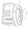
- FIG. 3is a perspective side view of the fluid tank receptacle of FIG. 1 .
- FIG. 4is a cross-sectional side view of the fluid tank receptacle of FIG. 1 showing the cage in a use position.
- FIG. 5is a perspective side view of the fluid tank receptacle of FIG. 1 showing a fluid tank received in the fluid tank receptacle.
- FIG. 6is a perspective side view of the fluid tank receptacle of FIG. 1 showing the accessory pole receptacle and transport handle.
- FIG. 7is a perspective side view of the fluid tank receptacle of FIG. 1 showing the cage in the use position.
- FIG. 8is a perspective top view of the fluid tank receptacle of FIG. 1 .
- FIG. 9is a bottom plan view of the fluid tank receptacle of FIG. 1 .
- FIG. 10is a partial cross-sectional view of the fluid tank receptacle of FIG. 1 showing the spring located in the slots in the housing at a first length when the cage is in a storage position.
- FIG. 11is a perspective view of the patient-support apparatus of FIG. 1 showing a first movable portion in a raised orientation with respect to the upper frame.
- One illustrative embodiment of the present disclosurecan include fluid tank storage assembly with cage configured to extend from the upper frame a first distance when a fluid tank is stored in the fluid tank storage assembly and retract toward the upper frame such that the cage is a second distance from the upper frame that can be less than the first distance when the fluid tank is not stored in the fluid tank storage assembly.
- Another illustrative embodiment of the present disclosurecan include an upper frame with an upper frame base supporting a deck with a seat section having stationary side portions coupled to the upper frame base and movable middle portions positioned between the stationary side portions that can be configured to cooperate with a head deck section and a foot deck section to move the upper frame between a substantially horizontal position and a chair position.
- FIGS. 1-11A person-support apparatus 10 according to one illustrative embodiment of the current disclosure is shown in FIGS. 1-11 .
- the person-support apparatus 10can be a hospital bed with a first section F 1 or head support section F 1 , where the head of a person (not shown) can be positioned and a second section S 1 or a foot support section S 1 , where the feet of the person (not shown) can be positioned.
- the person-support apparatus 10can also be a hospital stretcher or an operating table.
- the person-support apparatus 10can define a first longitudinal axis X 1 passing through the first section F 1 and the second section S 1 and a transverse axis Y 1 substantially perpendicular to the first longitudinal axis.
- the person-support apparatus 10can include a lower frame 12 or base 12 , a plurality of supports 14 coupled with the lower frame 12 and an upper frame 16 movably supported by the plurality of supports 14 above the lower frame 12 . It should be appreciated that the supports 14 can be lift mechanisms that can move the upper frame 16 with respect to the lower frame 12 . It should also be appreciated that in one illustrative embodiment, the person-support apparatus 10 can support a person-support surface 18 on the upper frame 16 .
- the upper frame 16can include an upper frame base 20 , a deck 22 , siderails 24 , endboards 26 , and an accessory support 28 as shown in FIGS. 1-2 and 11 .
- the upper frame base 20can be coupled with the supports 14 and can support the deck 22 thereon as shown in FIGS. 1 and 2 .
- the accessory support 28can be located at a head end 30 of the upper frame 16 . It should be appreciated that the accessory support 28 can be located at a foot end 32 of the upper frame 16 .
- the accessory support 28can include transport handles 34 , accessory pole receptacles 36 , and fluid tank receptacles 38 as shown in FIGS. 1-11 .
- accessory poles 40such as, for example, IV poles and/or line management devices, can be secured to the accessory support 28 .
- the transport handles 34can be configured to be gripped by a person and pushed to move the person-support apparatus 10 from one location to another.
- the accessory pole receptacles 36can be configured to removably retain accessory poles, such as, IV poles and/or line management equipment.
- the transport handles 34can include a curved portion 44 that can be configured to at least partially surround a portion of an accessory pole 40 received in the accessory pole receptacles 36 .
- the fluid tank receptacle 38can include a receptacle body 46 with an opening 48 therethrough, a bumper 50 , a retainer 52 , and a cage 54 as shown in FIGS. 1-10 .
- the opening 50can be sized to receive a fluid tank 56 , such as, for example, an oxygen tank, therein.
- the retainer 52can be secured to the receptacle body 46 and can be configured to couple the cage 54 to the receptacle body 46 and movably couple the bumper 50 to the receptacle body 46 .
- the retainer 52can include a plurality of holes 58 that can be configured to receive a portion of the cage 54 and fasteners used to secure the retainer 52 to the receptacle body 46 .
- the bumper 50can be configured to absorb some of the force generated when the bumper 50 collides with an object, such as, for example, a wall.
- the bumper 50can be positioned between the receptacle body 46 and the retainer 52 as shown in FIGS. 3, 4 and 7 .
- the bumper 50can be configured to rotate about a rotational axis R 1 passing through the center of the opening 48 . It should be appreciated that the ability of the bumper 50 to rotate can help reduce the force generated when the bumper 50 indirectly collides with an object, such as, a wall.
- the cage 54can be movably coupled to the receptacle body 46 and can be configured to move between a use position where the cage 54 supports a fluid tank 56 received within the fluid tank receptacle 38 , and a storage position.
- the cage 54can include a plurality of cage supports 60 , a support coupler 62 , and a plurality of springs 64 .
- the cage supports 60can include a first support end 66 and a second support end 68 .
- the first support end 66can be configured to pass through one of the holes 58 in the retainer 52 to slidably engage one of the cage support slots 70 in the receptacle body 46 .
- the second end 68can be configured to be coupled to the support coupler 62 .
- the cage supports 60can be U-shaped and the second end 68 can pass through another of the holes 58 to engage another of the cage support slots 70 .
- the first support end 66can include a retaining ring 72 coupled thereto and configured to cooperate with the spring 64 and/or the retainer 52 to maintain the first support end 66 within the cage support slot 70 .
- the spring 64can be located in the cage support slot 70 and can be configured to bias the cage 54 toward the storage position.
- the spring 64can be positioned between the retaining ring 72 and the retainer 52 as shown in FIG. 10 .
- the spring 64can be a first length when the cage 54 is in the storage position as shown in FIG. 10 and can be compressed to a second length when a fluid tank 56 engages the cage 54 and moves the cage 54 to the use position. It should be appreciated that the weight of the fluid tank 56 can cause the spring 64 to compress. When the fluid tank 56 is removed, the spring 64 can bias the cage 54 toward the storage position.
- the deck 22can include a head portion 74 , a seat portion 76 , and a foot portion 78 as shown in FIG. 11 .
- the head portion 74 , the seat portion 76 , and the foot portion 78can be movably coupled with each other and/or the upper frame base 20 and can be configured to cooperate with one another to move the deck 22 between a relatively horizontal position and a chair position as shown in FIG. 2 .
- the seat portion 76can include first and second outer portions 80 and 82 and first and second inner portions 84 and 86 .
- the first and second inner portions 84 and 86can be positioned between the first and second outer portions 80 and 82 .
- the first and second inner portions 84 and 86can be movable with respect to the upper frame base 20 .
- the first inner portion 84can be movably coupled to the second inner portion 84 at a first joint 88 and the second inner portion can be coupled to the foot portion 78 at a second joint 90 .
- the first and second outer portions 80 and 82can be stationary with respect to the upper frame base 20 . It should be appreciated that the first and second outer portions 80 and 82 can help reduce incidents of pinch points and maintain the spacing between the deck 22 and the siderails 24 as the first and second inner portions 84 and 86 move with respect to the upper frame base 20 .
- a person-support apparatuscomprises a lower frame, an upper frame, and a deck.
- the upper frameis movably supported above the lower frame by a support.
- the deckis supported on the upper frame, the deck includes a section with a first portion configured to be movable with respect to the upper frame and a second portion configured to be stationary with respect to the upper frame.
- the person-support apparatusis configured to be movable between a generally horizontal position and a chair position.
- a fluid tank receptaclecomprises a housing, a cage, and a retainer.
- the housingincludes an opening therethrough configured to receive a fluid tank.
- the cagemovably engages the housing and configured to support the fluid tank.
- the retaineris coupled to the housing and is configured to movably retain a portion of the cage within the housing such that the cage is able to move between a storage position and a use position with respect to the housing.
Landscapes
- Health & Medical Sciences (AREA)
- Engineering & Computer Science (AREA)
- Mechanical Engineering (AREA)
- Nursing (AREA)
- Life Sciences & Earth Sciences (AREA)
- Animal Behavior & Ethology (AREA)
- General Health & Medical Sciences (AREA)
- Public Health (AREA)
- Veterinary Medicine (AREA)
- General Engineering & Computer Science (AREA)
- Accommodation For Nursing Or Treatment Tables (AREA)
- Invalid Beds And Related Equipment (AREA)
Abstract
Description
Claims (16)
Priority Applications (1)
| Application Number | Priority Date | Filing Date | Title |
|---|---|---|---|
| US14/269,492US9333134B2 (en) | 2010-07-09 | 2014-05-05 | Medical gas tank receptacle for patient support apparatus |
Applications Claiming Priority (8)
| Application Number | Priority Date | Filing Date | Title |
|---|---|---|---|
| US12/833,321US8516634B2 (en) | 2010-07-09 | 2010-07-09 | Bed structure with a deck section motion converter |
| US12/836,606US9222685B2 (en) | 2010-07-15 | 2010-07-15 | Method and system for controlling evaporative and heat withdrawal performance of an occupant support surface |
| US36915210P | 2010-07-30 | 2010-07-30 | |
| US36949910P | 2010-07-30 | 2010-07-30 | |
| US12/847,337US8620625B2 (en) | 2010-07-30 | 2010-07-30 | Above bed sensor |
| PCT/US2011/043392WO2012006545A2 (en) | 2010-07-09 | 2011-07-08 | Person support systems, devices, and methods |
| US13/733,962US8713728B2 (en) | 2010-07-30 | 2013-01-04 | Medical gas tank holder for patient support apparatus |
| US14/269,492US9333134B2 (en) | 2010-07-09 | 2014-05-05 | Medical gas tank receptacle for patient support apparatus |
Related Parent Applications (1)
| Application Number | Title | Priority Date | Filing Date |
|---|---|---|---|
| US13/733,962ContinuationUS8713728B2 (en) | 2010-07-09 | 2013-01-04 | Medical gas tank holder for patient support apparatus |
Publications (2)
| Publication Number | Publication Date |
|---|---|
| US20140237720A1 US20140237720A1 (en) | 2014-08-28 |
| US9333134B2true US9333134B2 (en) | 2016-05-10 |
Family
ID=48570680
Family Applications (2)
| Application Number | Title | Priority Date | Filing Date |
|---|---|---|---|
| US13/733,962ActiveUS8713728B2 (en) | 2010-07-09 | 2013-01-04 | Medical gas tank holder for patient support apparatus |
| US14/269,492Active2031-09-04US9333134B2 (en) | 2010-07-09 | 2014-05-05 | Medical gas tank receptacle for patient support apparatus |
Family Applications Before (1)
| Application Number | Title | Priority Date | Filing Date |
|---|---|---|---|
| US13/733,962ActiveUS8713728B2 (en) | 2010-07-09 | 2013-01-04 | Medical gas tank holder for patient support apparatus |
Country Status (1)
| Country | Link |
|---|---|
| US (2) | US8713728B2 (en) |
Cited By (1)
| Publication number | Priority date | Publication date | Assignee | Title |
|---|---|---|---|---|
| US20200032960A1 (en)* | 2016-09-28 | 2020-01-30 | Linde Aktiengesellschaft | Cylinder holder, supply system and supply method for therapeutic oxygen |
Families Citing this family (6)
| Publication number | Priority date | Publication date | Assignee | Title |
|---|---|---|---|---|
| US8713728B2 (en) | 2010-07-30 | 2014-05-06 | Hill-Rom Services, Inc. | Medical gas tank holder for patient support apparatus |
| WO2015138317A1 (en) | 2014-03-10 | 2015-09-17 | Stryker Corporation | Limb positioning system |
| US9951904B2 (en) | 2015-03-24 | 2018-04-24 | Stryker Corporation | Rotatable seat clamps for rail clamp |
| CN107157681B (en)* | 2017-05-08 | 2020-04-14 | 金陵科技学院 | A curved transfer bed for moving patients |
| CN107158505B (en)* | 2017-05-27 | 2020-03-17 | 吉林大学 | Infusion chair with heat preservation function |
| CN107582268A (en)* | 2017-09-27 | 2018-01-16 | 袁敬涛 | It is a kind of multifunctional hospital bed |
Citations (50)
| Publication number | Priority date | Publication date | Assignee | Title |
|---|---|---|---|---|
| US1064248A (en)* | 1912-04-20 | 1913-06-10 | Jennie Pohle | Preserving-jar basket. |
| US1906590A (en)* | 1932-04-22 | 1933-05-02 | George E Hewson | Base protector |
| US3970344A (en) | 1975-12-11 | 1976-07-20 | Baumann Arthur V | Oxygen tank holder for wheelchairs |
| US4026435A (en)* | 1975-07-24 | 1977-05-31 | Hendon Joseph S | Disposable cookware |
| US4213648A (en) | 1978-08-17 | 1980-07-22 | Steichen Clemons P | Oxygen tank holding device for wheelchairs |
| US4431206A (en) | 1981-07-27 | 1984-02-14 | Pryor John W | Wheelchair medical accessory carrier |
| US4506903A (en)* | 1983-03-03 | 1985-03-26 | Ndk, Incorporated | Wheelchair attachment |
| US4696420A (en) | 1986-01-17 | 1987-09-29 | Helmut Kulik | Oxygen carrier |
| USD305629S (en) | 1987-11-17 | 1990-01-23 | Wood Charles F | Wheelchair-mounted oxygen bottle bracket |
| USD342222S (en) | 1992-06-08 | 1993-12-14 | Cherry Jeff D | Expandable oxygen tank bracket for a wheelchair |
| US5283919A (en) | 1991-11-29 | 1994-02-08 | Grant Fred W | Folding trauma stretcher |
| US5288001A (en) | 1993-06-07 | 1994-02-22 | Bel-Art Products, Inc. | Oxygen tank holder for use with wheelchairs |
| USD357217S (en) | 1993-08-24 | 1995-04-11 | Shirley Terry L | Oxygen cylinder bracket |
| US5556065A (en) | 1994-10-19 | 1996-09-17 | Wadley; Robert D. | Intensive care equipment carriage |
| US5715548A (en) | 1994-01-25 | 1998-02-10 | Hill-Rom, Inc. | Chair bed |
| US5788475A (en)* | 1996-11-05 | 1998-08-04 | Henderson; Mark | Aluminum scuba tank buoyancy compensation system |
| US5890687A (en) | 1996-07-22 | 1999-04-06 | Pryor Products | Foldable wheeled stand |
| US5966760A (en) | 1997-01-31 | 1999-10-19 | Hill-Rom, Inc. | Apparatus and method for upgrading a hospital room |
| US5996150A (en) | 1996-04-24 | 1999-12-07 | Blevins; Jerry L. | Cantilevered mobile bed/chair apparatus for safety patient transfer |
| US6170518B1 (en)* | 2000-04-04 | 2001-01-09 | James L. Ratelle | Apparatus for holding and transporting high pressure rescue air bag system components |
| US6325097B1 (en)* | 1997-01-31 | 2001-12-04 | Hill-Rom Services, Inc. | Manifold and regulator apparatus |
| US20020074755A1 (en)* | 2000-01-11 | 2002-06-20 | Burkett Jerald S. | Mobile compressed gas module |
| US6427270B1 (en) | 1997-04-11 | 2002-08-06 | Jerry L. Blevins | Cantilevered mobile bed/chair apparatus for safety patient transfer |
| US6585206B2 (en) | 2000-06-05 | 2003-07-01 | Hill-Rom Services, Inc. | Medical accessory support |
| US6672321B2 (en) | 2002-01-04 | 2004-01-06 | Roger H. Hamilton | Apparatus for containing and centering oxygen bottle on a walker |
| US6691349B2 (en) | 1997-04-11 | 2004-02-17 | Jerry Blevins | Patient bed with leg lifter |
| US20060021144A1 (en)* | 2004-07-30 | 2006-02-02 | Hornbach David W | Bed having a chair egress position |
| US7017208B2 (en) | 1995-08-04 | 2006-03-28 | Hill-Rom Services, Inc. | Hospital bed |
| USD528904S1 (en) | 2005-08-04 | 2006-09-26 | Reding Anthony C | Oxygen tank holder |
| US7124456B2 (en) | 2004-08-11 | 2006-10-24 | Stryker Corporation | Articulated support surface for a stretcher or gurney |
| US20070018058A1 (en)* | 2003-10-13 | 2007-01-25 | Graham Mark A | Equipment support having rotatable bumpers and hooks |
| US7188855B1 (en) | 2005-04-29 | 2007-03-13 | Thomas E Trevor | Articulating oxygen tank holder |
| US7243666B2 (en) | 2004-07-20 | 2007-07-17 | Carroll Donald K | Walker including supports for carrying oxygen bottles |
| US7338055B2 (en) | 2003-07-01 | 2008-03-04 | Carl Fuentes | Method and workstation for single patient medical care |
| US7370660B2 (en) | 2002-01-04 | 2008-05-13 | Hamilton Roger H | Oxygen bottle carrier appliance |
| US20080189858A1 (en)* | 2007-02-09 | 2008-08-14 | Pedigo Products, Inc. | Safe store oxygen bottle holder |
| US20080263769A1 (en)* | 2007-04-26 | 2008-10-30 | Hill-Rom Services, Inc. | Patient care equipment support transfer system |
| US7624463B2 (en)* | 2004-08-03 | 2009-12-01 | Hill-Rom Services, Inc. | Equipment support rail for hospital bed |
| US7648113B2 (en) | 2007-07-18 | 2010-01-19 | Ruben Johnson | Support for a cylindrically-shaped accessory |
| US20100077549A1 (en)* | 2003-05-21 | 2010-04-01 | Hensley David W | Hospital bed deck to frame attachment |
| US7731136B1 (en) | 2007-03-19 | 2010-06-08 | Cory Chisolm | Combined IV bag and oxygen supporting pole and associated method |
| USD618356S1 (en) | 2009-12-04 | 2010-06-22 | Nellcor Puritan Bennett Llc | Tank holder |
| US7844735B2 (en) | 2005-05-03 | 2010-11-30 | International Business Machines Corporation | Determining address of edge server by using authoritative domain name server and bypassing assigned domain name server |
| US20110010861A1 (en)* | 2009-07-15 | 2011-01-20 | Heimbrock Richard H | Transition Assist Siderail and Article Employing the Same |
| US7913337B1 (en) | 2005-05-31 | 2011-03-29 | Masson Marcos V | Ambulatory surgical gurney |
| US8011634B1 (en) | 2009-08-19 | 2011-09-06 | Johnson Dale A | Oxygen tank accessory apparatus |
| US20120110741A1 (en)* | 2010-11-04 | 2012-05-10 | Mears Brian E | Wrap around foot panel |
| US8240684B2 (en) | 2008-12-12 | 2012-08-14 | Nellcor Puritan Bennett Llc | Medical ventilator cart |
| US20130145551A1 (en) | 2010-07-30 | 2013-06-13 | Hill-Rom Services, Inc. | Medical gas tank holder for patient support apparatus |
| US20140097313A1 (en)* | 2011-09-12 | 2014-04-10 | Eric W. Hesketh | Portable Canister Holder with a Collapsible Body |
- 2013
- 2013-01-04USUS13/733,962patent/US8713728B2/enactiveActive
- 2014
- 2014-05-05USUS14/269,492patent/US9333134B2/enactiveActive
Patent Citations (63)
| Publication number | Priority date | Publication date | Assignee | Title |
|---|---|---|---|---|
| US1064248A (en)* | 1912-04-20 | 1913-06-10 | Jennie Pohle | Preserving-jar basket. |
| US1906590A (en)* | 1932-04-22 | 1933-05-02 | George E Hewson | Base protector |
| US4026435A (en)* | 1975-07-24 | 1977-05-31 | Hendon Joseph S | Disposable cookware |
| US3970344A (en) | 1975-12-11 | 1976-07-20 | Baumann Arthur V | Oxygen tank holder for wheelchairs |
| US4213648A (en) | 1978-08-17 | 1980-07-22 | Steichen Clemons P | Oxygen tank holding device for wheelchairs |
| US4431206A (en) | 1981-07-27 | 1984-02-14 | Pryor John W | Wheelchair medical accessory carrier |
| US4506903A (en)* | 1983-03-03 | 1985-03-26 | Ndk, Incorporated | Wheelchair attachment |
| US4696420A (en) | 1986-01-17 | 1987-09-29 | Helmut Kulik | Oxygen carrier |
| USD305629S (en) | 1987-11-17 | 1990-01-23 | Wood Charles F | Wheelchair-mounted oxygen bottle bracket |
| US5283919A (en) | 1991-11-29 | 1994-02-08 | Grant Fred W | Folding trauma stretcher |
| USD342222S (en) | 1992-06-08 | 1993-12-14 | Cherry Jeff D | Expandable oxygen tank bracket for a wheelchair |
| US5288001A (en) | 1993-06-07 | 1994-02-22 | Bel-Art Products, Inc. | Oxygen tank holder for use with wheelchairs |
| USD357217S (en) | 1993-08-24 | 1995-04-11 | Shirley Terry L | Oxygen cylinder bracket |
| US6336235B1 (en) | 1994-01-25 | 2002-01-08 | Hill-Rom Services, Inc. | Chair bed |
| US5715548A (en) | 1994-01-25 | 1998-02-10 | Hill-Rom, Inc. | Chair bed |
| US6163903A (en) | 1994-01-25 | 2000-12-26 | Hill-Rom Inc. | Chair bed |
| US5556065A (en) | 1994-10-19 | 1996-09-17 | Wadley; Robert D. | Intensive care equipment carriage |
| US8413274B2 (en) | 1995-08-04 | 2013-04-09 | Hill-Rom Services, Inc. | Hospital bed |
| US7017208B2 (en) | 1995-08-04 | 2006-03-28 | Hill-Rom Services, Inc. | Hospital bed |
| US8065764B2 (en) | 1995-08-04 | 2011-11-29 | Hill-Rom Services, Inc. | Hospital bed |
| US7784128B2 (en) | 1995-08-04 | 2010-08-31 | Hill-Rom Services, Inc. | Hospital bed |
| US7568246B2 (en) | 1995-08-04 | 2009-08-04 | Hill-Rom Services, Inc. | Bed with a networked alarm |
| US7480951B2 (en) | 1995-08-04 | 2009-01-27 | Hill-Rom Services, Inc. | Patient care bed with network |
| US7237287B2 (en) | 1995-08-04 | 2007-07-03 | Hill-Rom Services, Inc. | Patient care bed with network |
| US7213279B2 (en) | 1995-08-04 | 2007-05-08 | Weismiller Matthew W | Hospital bed and mattress having extendable foot section |
| US5996150A (en) | 1996-04-24 | 1999-12-07 | Blevins; Jerry L. | Cantilevered mobile bed/chair apparatus for safety patient transfer |
| US5890687A (en) | 1996-07-22 | 1999-04-06 | Pryor Products | Foldable wheeled stand |
| US5788475A (en)* | 1996-11-05 | 1998-08-04 | Henderson; Mark | Aluminum scuba tank buoyancy compensation system |
| US6360389B1 (en) | 1997-01-31 | 2002-03-26 | Hill-Rom Services, Inc. | Apparatus and method for upgrading a hospital room |
| US5966760A (en) | 1997-01-31 | 1999-10-19 | Hill-Rom, Inc. | Apparatus and method for upgrading a hospital room |
| US6325097B1 (en)* | 1997-01-31 | 2001-12-04 | Hill-Rom Services, Inc. | Manifold and regulator apparatus |
| US6427270B1 (en) | 1997-04-11 | 2002-08-06 | Jerry L. Blevins | Cantilevered mobile bed/chair apparatus for safety patient transfer |
| US6691349B2 (en) | 1997-04-11 | 2004-02-17 | Jerry Blevins | Patient bed with leg lifter |
| US20020074755A1 (en)* | 2000-01-11 | 2002-06-20 | Burkett Jerald S. | Mobile compressed gas module |
| US6170518B1 (en)* | 2000-04-04 | 2001-01-09 | James L. Ratelle | Apparatus for holding and transporting high pressure rescue air bag system components |
| US6585206B2 (en) | 2000-06-05 | 2003-07-01 | Hill-Rom Services, Inc. | Medical accessory support |
| US6966086B2 (en) | 2000-06-05 | 2005-11-22 | Hill-Rom Services, Inc. | Medical accessory support |
| US6672321B2 (en) | 2002-01-04 | 2004-01-06 | Roger H. Hamilton | Apparatus for containing and centering oxygen bottle on a walker |
| US7370660B2 (en) | 2002-01-04 | 2008-05-13 | Hamilton Roger H | Oxygen bottle carrier appliance |
| US20100077549A1 (en)* | 2003-05-21 | 2010-04-01 | Hensley David W | Hospital bed deck to frame attachment |
| US7338055B2 (en) | 2003-07-01 | 2008-03-04 | Carl Fuentes | Method and workstation for single patient medical care |
| US20070018058A1 (en)* | 2003-10-13 | 2007-01-25 | Graham Mark A | Equipment support having rotatable bumpers and hooks |
| US7243666B2 (en) | 2004-07-20 | 2007-07-17 | Carroll Donald K | Walker including supports for carrying oxygen bottles |
| US20060021144A1 (en)* | 2004-07-30 | 2006-02-02 | Hornbach David W | Bed having a chair egress position |
| US7624463B2 (en)* | 2004-08-03 | 2009-12-01 | Hill-Rom Services, Inc. | Equipment support rail for hospital bed |
| US7412735B2 (en) | 2004-08-11 | 2008-08-19 | Stryker Corporation | Patient support apparatus |
| US7124456B2 (en) | 2004-08-11 | 2006-10-24 | Stryker Corporation | Articulated support surface for a stretcher or gurney |
| US7395564B2 (en) | 2004-08-11 | 2008-07-08 | Stryker Corporation | Articulated support surface for a stretcher or gurney |
| US7188855B1 (en) | 2005-04-29 | 2007-03-13 | Thomas E Trevor | Articulating oxygen tank holder |
| US7844735B2 (en) | 2005-05-03 | 2010-11-30 | International Business Machines Corporation | Determining address of edge server by using authoritative domain name server and bypassing assigned domain name server |
| US7913337B1 (en) | 2005-05-31 | 2011-03-29 | Masson Marcos V | Ambulatory surgical gurney |
| USD528904S1 (en) | 2005-08-04 | 2006-09-26 | Reding Anthony C | Oxygen tank holder |
| US20080189858A1 (en)* | 2007-02-09 | 2008-08-14 | Pedigo Products, Inc. | Safe store oxygen bottle holder |
| US7731136B1 (en) | 2007-03-19 | 2010-06-08 | Cory Chisolm | Combined IV bag and oxygen supporting pole and associated method |
| US20080263769A1 (en)* | 2007-04-26 | 2008-10-30 | Hill-Rom Services, Inc. | Patient care equipment support transfer system |
| US7648113B2 (en) | 2007-07-18 | 2010-01-19 | Ruben Johnson | Support for a cylindrically-shaped accessory |
| US8240684B2 (en) | 2008-12-12 | 2012-08-14 | Nellcor Puritan Bennett Llc | Medical ventilator cart |
| US20110010861A1 (en)* | 2009-07-15 | 2011-01-20 | Heimbrock Richard H | Transition Assist Siderail and Article Employing the Same |
| US8011634B1 (en) | 2009-08-19 | 2011-09-06 | Johnson Dale A | Oxygen tank accessory apparatus |
| USD618356S1 (en) | 2009-12-04 | 2010-06-22 | Nellcor Puritan Bennett Llc | Tank holder |
| US20130145551A1 (en) | 2010-07-30 | 2013-06-13 | Hill-Rom Services, Inc. | Medical gas tank holder for patient support apparatus |
| US20120110741A1 (en)* | 2010-11-04 | 2012-05-10 | Mears Brian E | Wrap around foot panel |
| US20140097313A1 (en)* | 2011-09-12 | 2014-04-10 | Eric W. Hesketh | Portable Canister Holder with a Collapsible Body |
Cited By (1)
| Publication number | Priority date | Publication date | Assignee | Title |
|---|---|---|---|---|
| US20200032960A1 (en)* | 2016-09-28 | 2020-01-30 | Linde Aktiengesellschaft | Cylinder holder, supply system and supply method for therapeutic oxygen |
Also Published As
| Publication number | Publication date |
|---|---|
| US8713728B2 (en) | 2014-05-06 |
| US20140237720A1 (en) | 2014-08-28 |
| US20130145551A1 (en) | 2013-06-13 |
Similar Documents
| Publication | Publication Date | Title |
|---|---|---|
| US9333134B2 (en) | Medical gas tank receptacle for patient support apparatus | |
| EP3210586B1 (en) | Fluid tank receptacle for person support systems | |
| US8381337B2 (en) | Egress assist footboard | |
| US20120246830A1 (en) | Footboard egress design | |
| US7735788B2 (en) | Patient care equipment management system | |
| US10022490B2 (en) | Transformable intravenous pole and boom combination and method thereof | |
| JP6672446B2 (en) | Lateral arm extension for patient transport | |
| US20120198628A1 (en) | Manually removable foot section | |
| US20110197796A1 (en) | Overbed table assembly | |
| WO2012135118A1 (en) | Computer support station | |
| US20190374418A1 (en) | Two-Plane, Folding Patient Assist Handle | |
| US10098797B2 (en) | Endboard for a person support apparatus | |
| US9050228B2 (en) | Siderail latching mechanism | |
| US20120023665A1 (en) | Siderail handle | |
| US8484778B2 (en) | Side rail with two position storage feature | |
| JP6301649B2 (en) | Bedside structure | |
| US20110283456A1 (en) | Ingress/egress assist handle | |
| US20120011652A1 (en) | Siderail assembly | |
| JP6603497B2 (en) | Bed equipment | |
| JP2014161682A (en) | Moving and lifting chair | |
| WO2013049583A1 (en) | Person support accessory |
Legal Events
| Date | Code | Title | Description |
|---|---|---|---|
| AS | Assignment | Owner name:JPMORGAN CHASE BANK, N.A., AS COLLATERAL AGENT, ILLINOIS Free format text:SECURITY INTEREST;ASSIGNORS:ALLEN MEDICAL SYSTEMS, INC.;HILL-ROM SERVICES, INC.;ASPEN SURGICAL PRODUCTS, INC.;AND OTHERS;REEL/FRAME:036582/0123 Effective date:20150908 Owner name:JPMORGAN CHASE BANK, N.A., AS COLLATERAL AGENT, IL Free format text:SECURITY INTEREST;ASSIGNORS:ALLEN MEDICAL SYSTEMS, INC.;HILL-ROM SERVICES, INC.;ASPEN SURGICAL PRODUCTS, INC.;AND OTHERS;REEL/FRAME:036582/0123 Effective date:20150908 | |
| STCF | Information on status: patent grant | Free format text:PATENTED CASE | |
| AS | Assignment | Owner name:JPMORGAN CHASE BANK, N.A., AS COLLATERAL AGENT, ILLINOIS Free format text:SECURITY AGREEMENT;ASSIGNORS:HILL-ROM SERVICES, INC.;ASPEN SURGICAL PRODUCTS, INC.;ALLEN MEDICAL SYSTEMS, INC.;AND OTHERS;REEL/FRAME:040145/0445 Effective date:20160921 Owner name:JPMORGAN CHASE BANK, N.A., AS COLLATERAL AGENT, IL Free format text:SECURITY AGREEMENT;ASSIGNORS:HILL-ROM SERVICES, INC.;ASPEN SURGICAL PRODUCTS, INC.;ALLEN MEDICAL SYSTEMS, INC.;AND OTHERS;REEL/FRAME:040145/0445 Effective date:20160921 | |
| AS | Assignment | Owner name:HILL-ROM SERVICES, INC., ILLINOIS Free format text:RELEASE BY SECURED PARTY;ASSIGNOR:JPMORGAN CHASE BANK, N.A.;REEL/FRAME:050254/0513 Effective date:20190830 Owner name:ALLEN MEDICAL SYSTEMS, INC., ILLINOIS Free format text:RELEASE BY SECURED PARTY;ASSIGNOR:JPMORGAN CHASE BANK, N.A.;REEL/FRAME:050254/0513 Effective date:20190830 Owner name:HILL-ROM COMPANY, INC., ILLINOIS Free format text:RELEASE BY SECURED PARTY;ASSIGNOR:JPMORGAN CHASE BANK, N.A.;REEL/FRAME:050254/0513 Effective date:20190830 Owner name:WELCH ALLYN, INC., NEW YORK Free format text:RELEASE BY SECURED PARTY;ASSIGNOR:JPMORGAN CHASE BANK, N.A.;REEL/FRAME:050254/0513 Effective date:20190830 Owner name:MORTARA INSTRUMENT, INC., WISCONSIN Free format text:RELEASE BY SECURED PARTY;ASSIGNOR:JPMORGAN CHASE BANK, N.A.;REEL/FRAME:050254/0513 Effective date:20190830 Owner name:VOALTE, INC., FLORIDA Free format text:RELEASE BY SECURED PARTY;ASSIGNOR:JPMORGAN CHASE BANK, N.A.;REEL/FRAME:050254/0513 Effective date:20190830 Owner name:MORTARA INSTRUMENT SERVICES, INC., WISCONSIN Free format text:RELEASE BY SECURED PARTY;ASSIGNOR:JPMORGAN CHASE BANK, N.A.;REEL/FRAME:050254/0513 Effective date:20190830 Owner name:HILL-ROM, INC., ILLINOIS Free format text:RELEASE BY SECURED PARTY;ASSIGNOR:JPMORGAN CHASE BANK, N.A.;REEL/FRAME:050254/0513 Effective date:20190830 Owner name:ANODYNE MEDICAL DEVICE, INC., FLORIDA Free format text:RELEASE BY SECURED PARTY;ASSIGNOR:JPMORGAN CHASE BANK, N.A.;REEL/FRAME:050254/0513 Effective date:20190830 | |
| AS | Assignment | Owner name:JPMORGAN CHASE BANK, N.A., ILLINOIS Free format text:SECURITY AGREEMENT;ASSIGNORS:HILL-ROM HOLDINGS, INC.;HILL-ROM, INC.;HILL-ROM SERVICES, INC.;AND OTHERS;REEL/FRAME:050260/0644 Effective date:20190830 | |
| MAFP | Maintenance fee payment | Free format text:PAYMENT OF MAINTENANCE FEE, 4TH YEAR, LARGE ENTITY (ORIGINAL EVENT CODE: M1551); ENTITY STATUS OF PATENT OWNER: LARGE ENTITY Year of fee payment:4 | |
| AS | Assignment | Owner name:HILL-ROM HOLDINGS, INC., ILLINOIS Free format text:RELEASE OF SECURITY INTEREST AT REEL/FRAME 050260/0644;ASSIGNOR:JPMORGAN CHASE BANK, N.A.;REEL/FRAME:058517/0001 Effective date:20211213 Owner name:BARDY DIAGNOSTICS, INC., ILLINOIS Free format text:RELEASE OF SECURITY INTEREST AT REEL/FRAME 050260/0644;ASSIGNOR:JPMORGAN CHASE BANK, N.A.;REEL/FRAME:058517/0001 Effective date:20211213 Owner name:VOALTE, INC., FLORIDA Free format text:RELEASE OF SECURITY INTEREST AT REEL/FRAME 050260/0644;ASSIGNOR:JPMORGAN CHASE BANK, N.A.;REEL/FRAME:058517/0001 Effective date:20211213 Owner name:HILL-ROM, INC., ILLINOIS Free format text:RELEASE OF SECURITY INTEREST AT REEL/FRAME 050260/0644;ASSIGNOR:JPMORGAN CHASE BANK, N.A.;REEL/FRAME:058517/0001 Effective date:20211213 Owner name:WELCH ALLYN, INC., NEW YORK Free format text:RELEASE OF SECURITY INTEREST AT REEL/FRAME 050260/0644;ASSIGNOR:JPMORGAN CHASE BANK, N.A.;REEL/FRAME:058517/0001 Effective date:20211213 Owner name:ALLEN MEDICAL SYSTEMS, INC., ILLINOIS Free format text:RELEASE OF SECURITY INTEREST AT REEL/FRAME 050260/0644;ASSIGNOR:JPMORGAN CHASE BANK, N.A.;REEL/FRAME:058517/0001 Effective date:20211213 Owner name:HILL-ROM SERVICES, INC., ILLINOIS Free format text:RELEASE OF SECURITY INTEREST AT REEL/FRAME 050260/0644;ASSIGNOR:JPMORGAN CHASE BANK, N.A.;REEL/FRAME:058517/0001 Effective date:20211213 Owner name:BREATHE TECHNOLOGIES, INC., CALIFORNIA Free format text:RELEASE OF SECURITY INTEREST AT REEL/FRAME 050260/0644;ASSIGNOR:JPMORGAN CHASE BANK, N.A.;REEL/FRAME:058517/0001 Effective date:20211213 | |
| MAFP | Maintenance fee payment | Free format text:PAYMENT OF MAINTENANCE FEE, 8TH YEAR, LARGE ENTITY (ORIGINAL EVENT CODE: M1552); ENTITY STATUS OF PATENT OWNER: LARGE ENTITY Year of fee payment:8 |