US9333035B2 - Cooled microwave denervation - Google Patents
Cooled microwave denervationDownload PDFInfo
- Publication number
- US9333035B2 US9333035B2US14/032,013US201314032013AUS9333035B2US 9333035 B2US9333035 B2US 9333035B2US 201314032013 AUS201314032013 AUS 201314032013AUS 9333035 B2US9333035 B2US 9333035B2
- Authority
- US
- United States
- Prior art keywords
- tissue
- microwave antenna
- temperature
- catheter
- microwave
- Prior art date
- Legal status (The legal status is an assumption and is not a legal conclusion. Google has not performed a legal analysis and makes no representation as to the accuracy of the status listed.)
- Active - Reinstated, expires
Links
Images


Classifications
- A—HUMAN NECESSITIES
- A61—MEDICAL OR VETERINARY SCIENCE; HYGIENE
- A61B—DIAGNOSIS; SURGERY; IDENTIFICATION
- A61B18/00—Surgical instruments, devices or methods for transferring non-mechanical forms of energy to or from the body
- A61B18/18—Surgical instruments, devices or methods for transferring non-mechanical forms of energy to or from the body by applying electromagnetic radiation, e.g. microwaves
- A61B18/1815—Surgical instruments, devices or methods for transferring non-mechanical forms of energy to or from the body by applying electromagnetic radiation, e.g. microwaves using microwaves
- A—HUMAN NECESSITIES
- A61—MEDICAL OR VETERINARY SCIENCE; HYGIENE
- A61B—DIAGNOSIS; SURGERY; IDENTIFICATION
- A61B18/00—Surgical instruments, devices or methods for transferring non-mechanical forms of energy to or from the body
- A61B2018/00005—Cooling or heating of the probe or tissue immediately surrounding the probe
- A61B2018/00011—Cooling or heating of the probe or tissue immediately surrounding the probe with fluids
- A61B2018/00023—Cooling or heating of the probe or tissue immediately surrounding the probe with fluids closed, i.e. without wound contact by the fluid
- A—HUMAN NECESSITIES
- A61—MEDICAL OR VETERINARY SCIENCE; HYGIENE
- A61B—DIAGNOSIS; SURGERY; IDENTIFICATION
- A61B18/00—Surgical instruments, devices or methods for transferring non-mechanical forms of energy to or from the body
- A61B2018/00053—Mechanical features of the instrument of device
- A61B2018/00166—Multiple lumina
- A—HUMAN NECESSITIES
- A61—MEDICAL OR VETERINARY SCIENCE; HYGIENE
- A61B—DIAGNOSIS; SURGERY; IDENTIFICATION
- A61B18/00—Surgical instruments, devices or methods for transferring non-mechanical forms of energy to or from the body
- A61B2018/00053—Mechanical features of the instrument of device
- A61B2018/00214—Expandable means emitting energy, e.g. by elements carried thereon
- A61B2018/0022—Balloons
- A—HUMAN NECESSITIES
- A61—MEDICAL OR VETERINARY SCIENCE; HYGIENE
- A61B—DIAGNOSIS; SURGERY; IDENTIFICATION
- A61B18/00—Surgical instruments, devices or methods for transferring non-mechanical forms of energy to or from the body
- A61B2018/00053—Mechanical features of the instrument of device
- A61B2018/00273—Anchoring means for temporary attachment of a device to tissue
- A61B2018/00279—Anchoring means for temporary attachment of a device to tissue deployable
- A61B2018/00285—Balloons
- A—HUMAN NECESSITIES
- A61—MEDICAL OR VETERINARY SCIENCE; HYGIENE
- A61B—DIAGNOSIS; SURGERY; IDENTIFICATION
- A61B18/00—Surgical instruments, devices or methods for transferring non-mechanical forms of energy to or from the body
- A61B2018/00315—Surgical instruments, devices or methods for transferring non-mechanical forms of energy to or from the body for treatment of particular body parts
- A61B2018/00434—Neural system
- A—HUMAN NECESSITIES
- A61—MEDICAL OR VETERINARY SCIENCE; HYGIENE
- A61B—DIAGNOSIS; SURGERY; IDENTIFICATION
- A61B18/00—Surgical instruments, devices or methods for transferring non-mechanical forms of energy to or from the body
- A61B2018/00315—Surgical instruments, devices or methods for transferring non-mechanical forms of energy to or from the body for treatment of particular body parts
- A61B2018/00505—Urinary tract
- A61B2018/00511—Kidney
- A—HUMAN NECESSITIES
- A61—MEDICAL OR VETERINARY SCIENCE; HYGIENE
- A61B—DIAGNOSIS; SURGERY; IDENTIFICATION
- A61B18/00—Surgical instruments, devices or methods for transferring non-mechanical forms of energy to or from the body
- A61B2018/00315—Surgical instruments, devices or methods for transferring non-mechanical forms of energy to or from the body for treatment of particular body parts
- A61B2018/00505—Urinary tract
- A61B2018/00517—Urinary bladder or urethra
- A—HUMAN NECESSITIES
- A61—MEDICAL OR VETERINARY SCIENCE; HYGIENE
- A61B—DIAGNOSIS; SURGERY; IDENTIFICATION
- A61B18/00—Surgical instruments, devices or methods for transferring non-mechanical forms of energy to or from the body
- A61B2018/00315—Surgical instruments, devices or methods for transferring non-mechanical forms of energy to or from the body for treatment of particular body parts
- A61B2018/00529—Liver
- A—HUMAN NECESSITIES
- A61—MEDICAL OR VETERINARY SCIENCE; HYGIENE
- A61B—DIAGNOSIS; SURGERY; IDENTIFICATION
- A61B18/00—Surgical instruments, devices or methods for transferring non-mechanical forms of energy to or from the body
- A61B2018/00315—Surgical instruments, devices or methods for transferring non-mechanical forms of energy to or from the body for treatment of particular body parts
- A61B2018/00541—Lung or bronchi
- A—HUMAN NECESSITIES
- A61—MEDICAL OR VETERINARY SCIENCE; HYGIENE
- A61B—DIAGNOSIS; SURGERY; IDENTIFICATION
- A61B18/00—Surgical instruments, devices or methods for transferring non-mechanical forms of energy to or from the body
- A61B2018/00315—Surgical instruments, devices or methods for transferring non-mechanical forms of energy to or from the body for treatment of particular body parts
- A61B2018/00547—Prostate
- A—HUMAN NECESSITIES
- A61—MEDICAL OR VETERINARY SCIENCE; HYGIENE
- A61B—DIAGNOSIS; SURGERY; IDENTIFICATION
- A61B18/00—Surgical instruments, devices or methods for transferring non-mechanical forms of energy to or from the body
- A61B2018/00571—Surgical instruments, devices or methods for transferring non-mechanical forms of energy to or from the body for achieving a particular surgical effect
- A61B2018/00577—Ablation
- A—HUMAN NECESSITIES
- A61—MEDICAL OR VETERINARY SCIENCE; HYGIENE
- A61B—DIAGNOSIS; SURGERY; IDENTIFICATION
- A61B18/00—Surgical instruments, devices or methods for transferring non-mechanical forms of energy to or from the body
- A61B2018/00636—Sensing and controlling the application of energy
- A61B2018/00642—Sensing and controlling the application of energy with feedback, i.e. closed loop control
- A—HUMAN NECESSITIES
- A61—MEDICAL OR VETERINARY SCIENCE; HYGIENE
- A61B—DIAGNOSIS; SURGERY; IDENTIFICATION
- A61B18/00—Surgical instruments, devices or methods for transferring non-mechanical forms of energy to or from the body
- A61B2018/00636—Sensing and controlling the application of energy
- A61B2018/00696—Controlled or regulated parameters
- A61B2018/00702—Power or energy
- A—HUMAN NECESSITIES
- A61—MEDICAL OR VETERINARY SCIENCE; HYGIENE
- A61B—DIAGNOSIS; SURGERY; IDENTIFICATION
- A61B18/00—Surgical instruments, devices or methods for transferring non-mechanical forms of energy to or from the body
- A61B2018/00636—Sensing and controlling the application of energy
- A61B2018/00696—Controlled or regulated parameters
- A61B2018/00744—Fluid flow
- A—HUMAN NECESSITIES
- A61—MEDICAL OR VETERINARY SCIENCE; HYGIENE
- A61B—DIAGNOSIS; SURGERY; IDENTIFICATION
- A61B18/00—Surgical instruments, devices or methods for transferring non-mechanical forms of energy to or from the body
- A61B2018/00636—Sensing and controlling the application of energy
- A61B2018/00773—Sensed parameters
- A61B2018/00779—Power or energy
- A61B2018/00785—Reflected power
- A—HUMAN NECESSITIES
- A61—MEDICAL OR VETERINARY SCIENCE; HYGIENE
- A61B—DIAGNOSIS; SURGERY; IDENTIFICATION
- A61B18/00—Surgical instruments, devices or methods for transferring non-mechanical forms of energy to or from the body
- A61B2018/00636—Sensing and controlling the application of energy
- A61B2018/00773—Sensed parameters
- A61B2018/00791—Temperature
- A—HUMAN NECESSITIES
- A61—MEDICAL OR VETERINARY SCIENCE; HYGIENE
- A61B—DIAGNOSIS; SURGERY; IDENTIFICATION
- A61B18/00—Surgical instruments, devices or methods for transferring non-mechanical forms of energy to or from the body
- A61B18/18—Surgical instruments, devices or methods for transferring non-mechanical forms of energy to or from the body by applying electromagnetic radiation, e.g. microwaves
- A61B18/1815—Surgical instruments, devices or methods for transferring non-mechanical forms of energy to or from the body by applying electromagnetic radiation, e.g. microwaves using microwaves
- A61B2018/183—Surgical instruments, devices or methods for transferring non-mechanical forms of energy to or from the body by applying electromagnetic radiation, e.g. microwaves using microwaves characterised by the type of antenna
- A61B2018/1846—Helical antennas
- A—HUMAN NECESSITIES
- A61—MEDICAL OR VETERINARY SCIENCE; HYGIENE
- A61B—DIAGNOSIS; SURGERY; IDENTIFICATION
- A61B18/00—Surgical instruments, devices or methods for transferring non-mechanical forms of energy to or from the body
- A61B18/18—Surgical instruments, devices or methods for transferring non-mechanical forms of energy to or from the body by applying electromagnetic radiation, e.g. microwaves
- A61B18/1815—Surgical instruments, devices or methods for transferring non-mechanical forms of energy to or from the body by applying electromagnetic radiation, e.g. microwaves using microwaves
- A61B2018/1861—Surgical instruments, devices or methods for transferring non-mechanical forms of energy to or from the body by applying electromagnetic radiation, e.g. microwaves using microwaves with an instrument inserted into a body lumen or cavity, e.g. a catheter
Definitions
- the present inventionrelates to denervation, and more particularly to a system and method for performing denervation using a cooled microwave catheter introduced into a neighboring body lumen such as an artery.
- denervationa number of problematic human conditions can be treated by damaging certain nerves or groups of nerves, which is generally referred to as denervation.
- One example of a denervation procedure that has been found to produce beneficial effectsis renal denervation. It has been demonstrated in many subjects that surgical renal denervation by renal artery transection and re-anastomosis is effective in reducing noradrenaline content in the kidney and favorably impacts blood pressure in resistant hypertension patients. This has led to less invasive, percutaneous approaches that use RF energy to create focal ablation lesions in each renal artery. These approaches have been demonstrated clinically to be an improvement over surgical renal denervation but they still have several drawbacks.
- Renal nervesdo not merely travel parallel to the renal artery but, rather, twist around it.
- the discrete lesionsmust not be created at the same location along the length of the artery to completely block the renal nerve activity as that would result in unacceptable weakening of the artery and likely aneurism and possible rupture. It is therefore impossible to eliminate all nerve pathways by the discrete lesions.
- the present inventionhas the advantage of protecting the intervening bronchial tissue and not requiring the energy emitter to be electrically in contact with the tissue. An additional advantage is the potential for a shortened procedure time and easier procedure.
- Cooled RF deviceshave been disclosed (US2012/0016363A1) that also seek to accomplish this.
- the RF electrodemust be in electrical contact with tissue for this approach to work.
- This requires a more complex device to accomplish the necessary cooling and heatingis dependent upon tissue impedance which varies dramatically between smooth muscle, cartilage and fat.
- microwave heatingis accomplished by a travelling electromagnetic field so that the antenna need not be in contact with tissue.
- a more simple balloon structureis appropriate and the field will travel through tissue of differing dielectric constants and effectively heat the target nerve bundle.
- the resultis a temperature field that protects the mucosa, smooth muscle, glandular tissue and cartilage of the bronchus but controllably thermally ablates the targeted nerve bundle.
- microwave energyrefers generally to frequencies of energy that cause heating of tissue via dielectric absorption.
- U.S. Pat. No. 5,300,099discloses a device to treat BPH in the prostate transuretherally without destroying the urethra.
- the clinical objective of this technologyis to mimic the surgical resection (TURP) and thermally destroy as large a volume of prostate tissue as possible adjacent to a length of the urethra in a minimally invasive, office based procedure. This technology has been developed, FDA approved, and is available today.
- cooled microwave devicesinclude U.S. Publication No. 2003/0065317 (Rudie et al.) intended to provide a lesion as large as possible for treating soft tissue like renal cell carcinoma or liver tumors. In this case, it is not necessary to protect the tissue adjacent the device. Instead, cooling is used to enable a significantly larger thermal injury than an uncooled device by preserving the dielectric constant of the tissue adjacent the device and preventing undesirable cavitation that would occur with a non-cooled device.
- a cooled microwave devicehas not been disclosed that optimizes the geometry, three dimensional SAR distribution, excitation frequency, heat transfer coefficient, necessary safety mitigations, and therapy control algorithm for targeting of nerves without damage to the mechanically important tissue forming or adjacent to the wall of the body lumen in which the device is inserted, such as media and intima tissue of an artery in some examples.
- An antenna of the type disclosed in U.S. Pat. No. 5,300,099is particularly advantageous as it does not result in transmission line radiation.
- the antenna described in U.S. Pat. No. 5,300,099is optimized for creating a large volume of thermal injury suitable for treating a prostate or cancerous tumor in kidney or liver, for example.
- this antennamay be further adapted to be ideal for treating nerves by adaptations such as modification of antenna tuning/pitch to create a single smaller zone of SAR, adjusting the antenna pitch to create two small and separate zones of high SAR or separating the antenna coil from the coaxial cable to allow coolant flow to return within the antenna.
- the antenna's coil pitch/tuning/catheter loadingsuch that essentially all the significant specific absorption rate (SAR) field comes from one of the elements, thereby shortening the treatment length to make the 3D SAR more optimal for performing denervation.
- SARspecific absorption rate
- the radiation patternwill more closely resemble a point source, and causes the field to drop off more rapidly than would otherwise occur, allowing targeting of tissue closer to the device.
- the antennamay also be optimized by non-uniform coil pitch to produce two narrow SAR peaks that can create two separate circumferential zones of thermal injury and considerably lessen the likelihood that injured nerves might regenerate and result in loss of efficacy longer term.
- the adaptation described in the lattermay be applied to either former or middle adaptations.
- antennasare possible to produce, for example, a single narrow SAR field. These embodiments would not be optimal for creating a large zone of necrosis for treating a length of tissue, such as a prostate.
- An antenna that produces a single relatively narrow SAR in the center of the antennamay be particularly suitable for denervation, such as renal or bronchial denervation for example.
- Such an antennais not as suitable for treating a length of tissue, such as desired in the prostate, but can produce a radiation pattern that is suitably shortened or similar to a point source.
- the length of cooling protection in a microwave antenna-carrying cathetercan be shortened as desired to reduce the depth of cooling protection due to fringing field effects.
- the length of cooling protectionmay be longer than the radiation length from the microwave antenna as it is in the embodiments described below.
- Antenna lengthcan also be shortened to reduce penetration, also due to fringing effects.
- the dipolemay be made asymmetric such that only one element contributes meaningful SAR (likely the non-driven side). Alternate antenna embodiments are disclosed in more detail below.
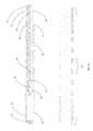
- FIGS. 1A-1Fare diagrams illustrating a microwave antenna-carrying catheter according to an embodiment of the present invention.
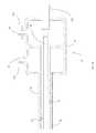
- FIG. 2is a detailed view of a microwave antenna-carrying catheter that includes cross sectional details.
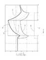
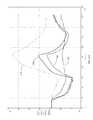
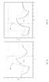
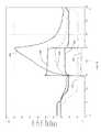
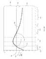
- FIGS. 3A-3Care graphs that illustrate a temperature profile achieved by a computer simulation of the operation of a microwave catheter for renal denervation as a function of time ( 3 A) and position ( 3 B and 3 C).
- FIGS. 4A and 4Bdepicts a renal artery guide catheter with and without the microwave carrying catheter placed within it.
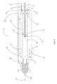
- FIGS. 4C and 4Dare more detailed diagrams of the distal and proximal regions of the guide catheter with microwave antenna carrying catheter placed within it.
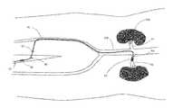
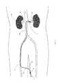
- FIG. 5Ais a diagram of the in-vivo placement of a guide catheter and microwave antenna carrying catheter to treat the renal nerves from within a renal artery.
- FIG. 5Bis a detailed view of the microwave treatment catheter placed within the renal artery along the longitudinal axis.
- FIG. 5Cis a detailed cross sectional view of the microwave antenna carrying catheter placed within the renal artery.
- FIG. 5Dis a cross sectional contour plot of the temperature field produced by microwave carrying catheter placed within the renal artery as in FIG. 5C .
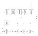
- FIG. 6is a flow chart illustrating the steps to perform renal denervation according to the present invention.
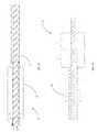
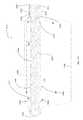
- FIG. 7Ais a detailed drawing of a microwave antenna carrying “needlestick” device of varying diameters.
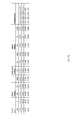
- FIG. 7Bis a table of tubing sizes used in the device of FIG. 7A .
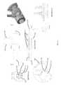
- FIGS. 8A-8Dare drawings of various prototype “needlestick” devices.
- FIG. 9is a drawing illustrating the catheter prototype of FIG. 7A configured with an ex vivo porcine renal artery surrounding the catheter and positioned within a gel-filled tube that serves as a phantom for the tissue and fat located around the renal artery.
- FIG. 10is a graph illustrating empirical temperature readings obtained from the bench simulation of microwave based renal denervation therapy as shown in FIG. 9 using a prototype device as shown in FIG. 7A .
- FIG. 11is a graph illustrating a computer simulation of the bench simulation that resulted in the graph of FIG. 10 .
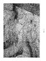
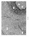
- FIGS. 12 and 13are photographs illustrating a catheter prototype and temperature probes inserted into a right renal artery of a porcine carcass.
- FIG. 14Ais a graph illustrating temperature data obtained in a region of the right renal artery during the porcine study shown in FIGS. 12 and 13 .
- FIG. 14Bis a graph illustrating specific temperature data obtained in a region of the right renal artery during the porcine study shown in FIGS. 12 and 13 .
- FIG. 14Cis a graph illustrating a computer simulation of the specific temperature data plotted in FIG. 14B .
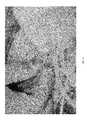
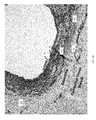
- FIGS. 15-18are photographs illustrating a catheter prototype and temperature probes inserted into a left renal artery of a porcine carcass.
- FIG. 19Ais a graph illustrating temperature data obtained in a region of the left renal artery during the porcine study shown in FIGS. 15-18 .
- FIG. 19Bis a graph illustrating specific temperature data obtained in a region of the left renal artery during the porcine study shown in FIGS. 15-18 .
- FIG. 19Cis a graph illustrating a computer simulation of the specific temperature data plotted in FIG. 19B .
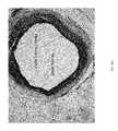
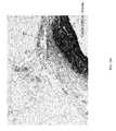
- FIGS. 20A-20Care histology slides that demonstrate thermal destruction of renal nerves without any damage to the intima and media of a representative porcine renal artery using a prototype device as shown in FIGS. 7A and 7B in accordance with the present invention.
- FIG. 20Dis a graph of the microwave power, microwave reflected power, coolant temperature, and tissue temperatures in the region of a porcine renal artery during microwave renal denervation in accordance with the present invention that produced the histology sections shown in FIGS. 20A-20C .
- FIGS. 21A, 22A, 23A and 24Aare additional histology slides of representative porcine arteries.
- FIGS. 21B, 22B, 23B and 24Bare additional representative graphs of microwave power, microwave reflected power, coolant temperature, and tissue temperatures in the region of a porcine renal artery during microwave renal denervation in accordance with the present invention that produced the accompanying histology sections depicted in FIGS. 21A, 22A, 23A and 24A .
- FIG. 25is a flowchart illustrating treatment algorithm steps used to accomplish renal denervation.
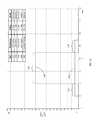
- FIG. 26is a graph of treatment parameters for accomplishing renal denervation using constant applied microwave power and constant coolant temperature.
- FIG. 27is a graph of alternate treatment parameters for accomplishing renal denervation using an exponentially decaying microwave power function.
- FIG. 28is a diagram of an antenna embodiment suitable for microwave renal denervation that uses two separate antenna coils.
- FIG. 29is a diagram of an alternate antenna embodiment suitable for microwave renal denervation that uses two separate antenna coils.
- FIG. 30is a graph of a normalized SAR pattern for the dual coil antenna embodiments depicted in FIGS. 28 and 29 .
- FIG. 31is a diagram of the antenna embodiment as described in U.S. Pat. No. 5,300,099.
- FIG. 32is a diagram of a modification to the embodiment depicted in FIG. 31 to enable the creation of two narrow circumferential thermal injury zones for microwave renal denervation.
- FIG. 33is a graph of a normalized SAR pattern for the antenna embodiments depicted in FIGS. 31 and 32 .
- FIG. 34is a diagram of an additional alternate modification to the embodiment depicted in FIG. 31 to enable the creation a single narrow circumferential thermal injury zone for microwave denervation.
- FIG. 35is a graph of a normalized SAR pattern for the antenna embodiments depicted in FIG. 31 and FIG. 34 .
- FIG. 36is a diagram of another antenna embodiment wherein the antenna coil is configured to be placed within the cooling balloon rather than within the catheter body wall.
- FIG. 37is a more detailed diagram of the device embodied in FIG. 1F . It includes details of the antenna depicted in FIG. 36 and the inner wall has been re-scaled to better illustrate cooling flow.
- FIG. 38is a revised diagram of the device embodied in FIG. 1B . It includes the re-scaled inner wall as in FIG. 37 to better illustrate cooling flow.
- FIG. 39is a diagram of a tip embodiment that is compatible with a guide wire to allow introduction and positioning with a guide wire instead of or in addition to a guide catheter as may be preferred by certain physicians.
- FIG. 40is a diagram of an end-fed antenna embodiment.
- FIGS. 41A-41Dare drawings of a catheter embodiment as fabricated for testing.
- FIG. 42is a photograph of a tissue equivalent phantom containing sheets of Liquid Crystal Temperature sensing film that enables visualization of the temperature field produced by the present embodiment.
- FIG. 43is a graph of the microwave power, microwave reflected power, coolant temperature, and tissue temperatures in the region of a porcine renal artery during microwave renal denervation in accordance with the present embodiment that produced the histology sections shown in FIGS. 44A-44D .
- FIGS. 44A-44Dare histology slides that demonstrate thermal destruction of renal nerves without any damage to the intima and media of a representative porcine renal artery using the present embodiment in accordance with the present invention.
- FIG. 44Eis a histology slide depicting viable tissue throughout as evidenced by NBT positive staining.
- FIGS. 45A-45Care computer simulation graphs that illustrate the importance of cooling to protect intima and media tissues.
- FIGS. 46A-46Fare diagrams illustrating a microwave antenna-carrying catheter according to another embodiment of the present invention.
- FIG. 47is a detailed view of the microwave antenna-carrying catheter of FIGS. 46A-46F that includes cross sectional details.
- FIG. 48A-48Dare graphs that illustrate a temperature profile achieved by a computer simulation of the operation of a microwave catheter for pulmonary denervation as a function of time ( 48 A) and position ( 48 B, 48 C and 48 D).
- FIGS. 49A and 49Bdepict a guide catheter with and without a microwave carrying catheter placed within it.
- FIGS. 49C and 49Dare more detailed diagrams of the distal and proximal regions of the guide catheter with a microwave antenna carrying catheter placed within it.
- FIG. 50is a cross section of a primary bronchus just beyond the carina of the trachea.
- FIG. 51Ais a detailed view of the microwave treatment catheter placed within the bronchial tree.
- FIG. 51Bis a detailed cross sectional view of the microwave antenna carrying catheter placed within a bronchus.
- FIG. 52Ais a cross sectional diagram of a bronchus with the microwave antenna carrying catheter placed within and the balloon inflated.
- FIG. 52Bis a cross sectional contour plot of temperature data from the microwave carrying catheter in which the maximum temperature is targeted at a nerve bundle depicted in FIG. 52A .
- FIG. 53is a flow chart illustrating the steps to perform pulmonary denervation according to an embodiment of the present invention.
- the concepts and principles of the present disclosureprovide devices and methods for inserting a catheter in a body lumen to create a lesion in tissue where targeted nerves are located, while preserving tissue adjacent to and forming the wall of the body lumen.
- the lesion that is createdmay be circumferential in shape, meaning that the lesion is generally (although typically not precisely) donut-shaped surrounding the renal artery (or other body lumen in which the catheter is inserted).
- a device and methodare provided to create a lesion in the adventitia and/or immediate adjacent surrounding tissue of a renal artery, so that the renal nerves located in the adventitia and/or immediate adjacent surrounding tissue are thermally damaged, while protecting the intima and media of the renal artery from injury.
- This approachis designed to more completely transect the renal nerves and achieve therapeutic effects in resistant hypertension patients with similar or greater efficacy to those that have been seen and reported by systems utilizing RF ablation to damage the renal nerves, without the damage to the renal artery and the inconvenience of manual manipulation of the RF ablation device.
- An additional advantageis a shortened procedure time and easier procedure without the need for multiple burns and manipulations.
- FIGS. 1A-1Eare diagrams illustrating microwave antenna-carrying catheter 10 according to an embodiment of the present invention.
- catheter 10includes proximal portion 12 , middle portion 14 , and distal portion 16 .
- FIG. 1Bis an enlarged view of proximal portion 12 of catheter 10 .
- Catheter 10includes outer body wall 20 and inner body wall 22 , between which a space is defined for the flow of coolant.
- coolant intake/exhaust structure 24is provided, with walls configured to provide a coolant input port 26 that communicates with the space between outer body wall 20 and inner body wall 22 of catheter 10 , and also to provide a coolant output port 28 that communicates with an interior of catheter 10 formed by coaxial cable 30 and the inside inner body wall 22 .
- Coaxial cable 30is provided to the interior of catheter 10 inside inner body wall 22 , is coupled to a microwave antenna 46 ( FIG. 1D ) at distal portion 16 ( FIG. 1A ) of catheter 10 , and is coupled to a microwave generator (not shown) to supply power to the microwave antenna via coaxial cable 30 .
- FIG. 1Cis an enlarged view of middle portion 14 of catheter 10 , showing outer body wall 20 , inner body wall 22 , coaxial cable 30 , and interior region for coolant to flow within catheter body walls 39 .
- These componentsmake up the flexible shaft of catheter 10 that is able to be guided into the renal artery of a patient via a femoral artery, for example.
- the lengthis suitable to conveniently be inserted into the femoral artery and reach the renal artery or may be adjusted to accommodate other insertion locations such as the subclavian or common carotid arteries.
- FIG. 1Dis an enlarged view of distal portion 16 of catheter 10 .
- balloon 40is attached to outer body wall 20 of catheter 10 to form interior region 41 for cooling fluid to inflate balloon 40 .
- Cooling fluid pressureis responsible for inflation of the balloon and may be controlled by an external pressure regulator (not shown) incorporated into the tubing or control console connected to catheter 10 .
- Balloon 40is attached to tip 42 at a distal end of distal portion 16 of catheter 10 .
- Balloon 40may be fabricated of compliant material, non-compliant material, or material that blends these characteristics.
- Return ports 44are provided in inner body wall 22 of catheter 10 to allow cooling fluid to exit balloon 40 and flow in a return path toward proximal portion 12 ( FIG.
- FIGS. 28, 29, 32, 34 and 36Additional details of various antenna embodiments are depicted in FIGS. 28, 29, 32, 34 and 36 .
- a temperature sensor 32is positioned on the surface of balloon 40 to monitor the temperature of the intima 96 during the treatment. The temperature reading may be used to control treatment parameters and/or to ensure safety.
- FIG. 1Edepicts an embodiment of catheter 10 without a temperature sensor 32 .
- this sensoris not necessary and it simplifies catheter 10 and also eliminates the possibility of non-uniform heat transfer between intima 96 of renal artery 94 and coolant within balloon 41 .
- FIG. 1Fdepicts an embodiment of catheter 10 that locates antenna coil 48 within balloon 40 rather than within the catheter body wall. Coolant flows between inner body wall 22 and outer body wall 20 , through spacer 56 , and into interior region 41 formed by balloon 40 as before. However, antenna coil 48 is placed within this region as well, separated only by shrink tubing 50 from coolant within 41 . Coolant then flows through ports 44 as before but in this embodiment coolant will flow between coaxial cable jacket 30 and inner body wall 22 within the antenna. Specific antenna adaptations to permit this flow of coolant and seal coolant from interior regions of coaxial cable 30 are depicted in FIG. 36 and described below.
- FIG. 2is a diagram of more details of distal portion 16 of catheter 10 including cross sectional views of the balloon 40 , of the coaxial cable spacer 56 , and of the shaft of catheter 10 .
- Cross section 74corresponds to section A-A and includes balloon 40 , region 41 for coolant to flow inside balloon 40 , coaxial cable 30 , antenna coil 48 , antenna shrink tubing 50 , and a region 39 within which coolant flows between the antenna and inner body wall 22 .
- the outer body wall 20does not extend into balloon 40 beyond spacer 56 .
- Cross section 76corresponds to section B-B and includes coaxial cable spacer 56 containing ports 44 for coolant to flow in the return path, inner body wall 22 , outer body wall 20 , an inner region 39 for coolant to flow, and balloon 40 bonded to outer body wall 20 .
- Cross section 78corresponds to section C-C and includes coaxial cable 30 , inner body wall 22 , outer body wall 20 , and regions 39 for coolant to flow within the catheter body walls 20 and 22 .
- a computer simulation of operation of a microwave catheter for renal denervationwas performed to illustrate the temperature profile that could be expected to be achieved.
- the simulationwas configured with the following parameters and assumptions:
- This equationis an energy balance that simply states the sum of conductive heat flow minus convective heat due to blood flow plus heat generation from an external source (microwave) plus metabolic heating gives rise to temperature elevation.
- the metabolic component Q m ⁇ Qcan be neglected.
- thermophysical properties for artery, fat, and bloodwere used and are given as:
- the dielectric constant of porcine artery and surrounding fatwas measured using an HP 85070 probe, HP 8753D network analyzer and associated dielectric probe software. The measured values were used to compute the wave equation and resulting form of the SAR term.
- the measured dielectric values at the operating frequency of 915 MHzare:
- FIG. 3Ais a graph of a representative simulation as described above as a function of time.
- coolant flow at a temperature of 6° C. ( 142 )is initiated 10 seconds prior to initiating microwave power ( 140 ) at a constant 55 Watts for 60 seconds.
- coolant flow 142is maintained at 6° C. for 30 seconds.
- Simulated temperatures corresponding to intima ( 144 ), media ( 146 ), adventitia ( 148 ) and surrounding fat ( 150 )are plotted.
- Thermal injurydepends on the entire thermal history (time & temperature) and depends upon the specific tissue. However, it can be appreciated that this simulation depicts a greater than 20° C. temperature difference between the target tissue 148 (nerves within the adventitia and immediate surrounding tissue) and the intima 144 .
- FIG. 3Bis a graph illustrating the temperature profile achieved by the computer simulation described above and plotted as a function of time in FIG. 3A at a specific time so that the temperature distribution as a function of distance from the intima may be visualized.
- Tissue temperature 160is plotted against position in units of mm so that it can be clearly seen that the maximum temperature (of about 53° C.) occurs at a distance of about 1.5 mm-2.0 mm (e.g., 1.6 mm) from the intima, which is the location of the target nerves for renal denervation, while the temperature within 0.5 mm of the intima is held below about 40° C. and temperature of the intima is held between about 30° C. and 35° C.
- a representative thermal injury threshold for a sample treatment durationis depicted by line 162 and basal body temperature is indicated by line 164 .
- tissue located between about 1.2 mm and about 2.1 mmwill be irreversibly thermally injured.
- the majority of renal nervesmay be located in this 1.2-2.1 mm window where highest temperatures are achieved (in other examples, the renal nerves may be located further from the intima, such as up to 4.0 mm or further in some examples, so that a deeper extending window would be used).
- the very steep temperature gradient between the intima and the maximum temperature regionallows renal nerves to be damaged sufficiently to effectively achieve renal denervation therapy, while protecting the intima and media of the renal artery wall from damage. Further, the decay in temperature beyond 2.1 mm is sufficient to ensure no damage to adjacent structures such as the renal vein or the vasovasorum.
- the specific area in which maximum temperatures are achieved, and the temperature values achieved,can be adjusted by adjusting parameters such as power provided to the microwave antenna as a function of time, coolant temperature as a function of time, microwave duration, volume of coolant provided around the microwave antenna, and others.
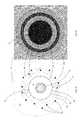
- FIG. 3Cdepicts an extension of the 1-dimensional simulation to a 2-dimensional contour plot cross section within the treatment zone.
- the catheter 10is placed in the middle and the first contour line represents intima temperature ( 144 ).
- the next contour linerepresents media temperature ( 146 ).
- the adventitia temperature ( 148 )is the maximum temperature and is a dark red ring on the contour plot. This is the region of thermal injury. Beyond the adventitial temperature is the surrounding tissue temperature 150 , largely fatty tissue, and beyond that is basal temperature 164 .
- FIG. 4Ais a diagram of a commonly available renal artery guide catheter 80 . It includes a tip 84 , a central shaft 82 , and a manifold 86 .
- FIG. 4Bis a diagram of catheter 10 placed within guide catheter 80 .
- Distal portion 16 of catheter 10extends just beyond tip 84 when the proximal end 12 is conveniently close to manifold 86 .
- FIG. 4Cis a diagram of the distal portion 16 of catheter 10 exiting guide catheter tip 84 .
- FIG. 4Dis a diagram of the proximal portion 12 of catheter 10 entering manifold 86 of guide catheter 80 .
- FIG. 5Ais a diagram of the in-vivo placement of catheter 10 using guide catheter 80 within a human body.
- guide catheter 80is introduced into femoral artery 92 through access site 90 near the groin of a patient and advanced into the abdominal aorta 108 and into the renal artery 94 under CT guidance as known in the art.
- Microwave antenna carrying catheter 10is introduced into guide catheter 80 by manifold 86 and advanced until deflated balloon 40 and microwave antenna 46 are fully extended beyond tip 84 of guide catheter 80 and positioned within the renal artery 94 in the region where renal nerves 102 are targeted for treatment. The position is confirmed by CT prior to initiating the treatment algorithm. Kidneys 106 are also shown.
- FIG. 5Bis an exploded diagram of the in-vivo placement of balloon 40 and antenna 46 within renal artery 94 .
- Balloon 40is inflated by circulating cooling fluid to contact intima 96 of renal artery 94 .
- the mediais depicted by 98 , adventitia by 100 , and surrounding tissue by 104 .
- the renal nerves, 102are not shown in this drawing but are contained within the adventitia 100 and the immediate adjacent surrounding tissue 104 .
- cooling fluidis circulated through the space 39 between outer body wall 20 and inner body wall 22 to interior region 41 of balloon 40 , so that balloon 40 is inflated to be in contact with the wall of the renal artery. Proper inflation of balloon 40 may be confirmed by CT.
- microwave poweris then initiated according to the treatment algorithm and is supplied by a microwave generator to coaxial cable 30 , which feeds microwave antenna 46 and causes microwave energy to be emitted omnidirectionally at distal portion 16 of catheter 10 within renal artery 94 .
- the microwave energy emitted by microwave antenna 46causes tissue temperature to increase in the area surrounding microwave antenna 46 , while cooling fluid circulating through balloon 40 cools the tissue immediately surrounding catheter 10 .
- tissue immediately surrounding distal portion 16 of catheter 10(such as the intima of the renal artery) is maintained at a temperature where thermal damage will not occur, while tissue surrounding distal portion 16 of catheter 10 that is spaced some distance from inflated balloon 40 (such as the advantitia of the renal artery where the renal nerves are located) is heated to a temperature sufficient to cause thermal damage to the tissue.
- tissue surrounding distal portion 16 of catheter 10 that is spaced some distance from inflated balloon 40such as the advantitia of the renal artery where the renal nerves are located
- Thisallows renal denervation to be performed without damaging the renal artery, in a single energization procedure that can cause the necessary thermal injury to the renal nerves in 30 to 120 seconds in some embodiments (although shorter or longer treatment times are desirable in other embodiments).
- FIG. 5Cis a diagram illustrating a cross section of catheter 10 placed in the renal artery of a patient during renal denervation.
- Microwave antenna 46is shown in the center of the balloon 40 placed within renal artery 94 .
- the intima 96is in contact with balloon 40 such that heat transfer between intima 96 and the cooling fluid in the interior 41 of balloon may occur to keep intima 96 cooled and protected from thermal injury—this concept can be referred to as “thermal contact” between the cooling fluid and intima 96 , through the wall of balloon 40 .
- Media 98immediately surrounds intima 96 and is cooled by heat transfer to intima 96 .
- the adventitia 100and immediately adjacent surrounding tissue 104 , are the location of the renal nerves 102 . More distant surrounding tissue 104 does not receive sufficient heat to cause thermal damage, nor does other tissue maintained close to basal temperature 150 .
- FIG. 5Dis another simulation contour plot as described above for FIG. 3C but here it is scaled to match the size of the renal artery cross section so that the precise targeting of renal nerves by the temperature field can be appreciated.
- the maximum temperature contour lines 148coincide with adventitia 100 and immediately adjacent surrounding tissue 104 . This is the precise location of the renal nerves 102 as shown in FIG. 5C . It can also be appreciated that the intima temperature 144 and media temperature 146 are located on cooler contour lines and therefore do not experience thermal damage. Temperature at distant tissue 150 is maintained very near basal temperature.
- FIG. 6is a flowchart that depicts steps for the placement of the microwave carrying catheter 10 within the renal artery 94 to accomplish renal denervation in accordance with the present invention.
- the patientis prepped as is well known in the art, and the femoral artery or another site such as the subclavian artery is accessed.
- a guide catheteris inserted according to FIG. 5A and advanced into the femoral artery 92 and advanced until the distal tip 84 of guide catheter 80 is positioned within renal artery 94 using techniques known in the art. This is commonly accomplished with the use of CT guidance and the proper position of tip 84 within renal artery 94 may also be verified by CT guidance.
- Microwave antenna containing catheter, 10is advanced into guide catheter 80 and positioned such that the entire balloon 40 is contained within the renal artery 94 and the antenna coil windings 48 are placed adjacent to the desired site for renal denervation. Verification of the location of balloon 40 is critical to successful renal denervation so it is checked and repositioned as necessary. Once properly located, renal denervation is initiated according to FIG. 25 to be described in detail later. Proper inflation of balloon 40 by cooling fluid within interior 41 is also verified before initiating microwave power 140 . Once the renal denervation treatment algorithm is completed, the balloon 40 will deflate when cooling flow is discontinued. The microwave carrying catheter 10 may then be removed from guide catheter using techniques known in the art.
- the other renal arteryis treated as described above, and then the catheter 10 may be removed.
- the last stepsare to remove guide catheter 80 and close or plug the puncture in femoral artery 92 in accordance with known techniques.
- the patient's insertion siteis then closed and the patient is monitored as is known in the art.
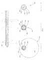
- FIG. 7Ais a drawing of a “needlestick” microwave antenna carrying catheter that mimics the geometry of antenna carrying catheter 10 when balloon 40 is inflated to varying sizes.
- This deviceis rigid and does not inflate so it cannot navigate the arterial system as described above but can access the renal artery through a surgical cut down.
- this deviceis comprised of an antenna tube 120 surrounded by spoke tubes 118 of various dimensions and number to fit within an outer tube 116 of varying diameter.
- FIG. 7Bis a table that indicates tubing sizes and configuration (number of spoke tubings) to fabricate different diameter devices.
- the material for the outer tubing 116 , spoke tubing 118 , and antenna tubing 120is thin wall PEEK tubing.
- Coolant exchange holes 130are punched in outer tubing 116 so that coolant may communicate between manifold formed by manifold tube 112 and spacer tubes 114 that may be silicone or another convenient material.
- Manifold tubing 112communicates with coolant inlet tubing 126 and coolant exhaust tubing 128 , both bonded to manifold tubing with UV cure silicone adhesive.
- Antenna tubing 120 and spoke tubing 118are cut to length to fit within outer tubing 116 and arranged as shown in the cross section inset on FIG. 7A .
- every other spoke tubeis a shorter length such that a dam of adhesive 124 may be injected into the region between the longer spoke tubing, antenna tubing, and outside tubing in the vicinity of the center of manifold tubing 112 .
- the coolant exchanges at 134and flows back through the longer spoke tubes through the coolant exchange holes 130 and on to the exhaust tubing 128 via the manifold tubing 112 and manifold spacer tubing 114 .
- the antenna tubing 120 and outside tubing 116are sealed at the distal end by plug 122 formed by adhesive.
- the adhesive used for plug 122 and potting 124may be a UV cure adhesive such as Loctite® 3311 or 3341.
- the adhesive used to bond inlet and outlet tubing ( 126 and 128 ) to manifold tubing 112may be UV cure silicone adhesive such as Loctite® 5083. In some sizes, it is useful to include a shim 132 to help keep the spoke tubing 118 and antenna tubing 120 stationary.
- the tubesare all of equal length and potting is applied in the space between tubes in the vicinity of the center of the manifold tubing. In this case, coolant flows down to exchange area 134 in the spaces between the spoke tubes and returns within the spoke tubes.
- spoke tubing shims 136as shown in FIG. 8A to allow coolant to flow between the spoke tubes and communicate with coolant exchange holes 130 .
- FIG. 8B-8Dare drawings of various size devices that were fabricated to perform bench and animal testing of microwave renal denervation in accordance with the present invention.
- FIG. 8Ais a 6.76 mm O.D. device and, per table in FIG. 7B , contains 7 spoke tubes 118 of 0.102′′ O.D. surrounding the antenna tube 120 also of 0.102′′ O.D.
- FIG. 8Ahas reference numbers to mark components as described above. Spoke tubing shim 136 is visible extending through coolant exchange holes 130 .
- FIG. 8Bis a 5.36 mm O.D. device and is fabricated with the use of spoke tubing shims 136 .
- FIG. 8Cis also a 5.36 mm O.D. device but is fabricated using alternate short/long length spoke tubes 118 separated by adhesive potting 124 .
- the alternate length spoke tubing 118 adhesive potting, 124 , and coolant exchange holes 130are clearly visible. There is one coolant exchange hole 130 centered on the location of each of the short spoke tubes.
- FIG. 8Dis a 4.24 mm O.D. device and is fabricated using alternate short/long length spoke tubes 118 separated by adhesive potting 124 . Fourteen (14) spoke tubes 118 are visible surrounding antenna tube 120 .
- FIG. 9is a drawing illustrating the needlestick catheter prototype 110 as described above configured with an ex vivo renal artery 94 surrounding the catheter positioned within a tissue phantom gel 170 filled in a tube that serves as a phantom for the tissue and fat located around the renal artery.
- Fiber optic temperature probe 172is placed between the intima 96 of renal artery 94 and the outer tubing 116 of needlestick device 110 to enable direct measurement of intima temperature.
- Additional fiber optic temperature probe 172is placed between the adventitia 110 and tissue phantom gel 170 to capture temperature at the location of renal nerves 102 .
- Fiber optic temperature probes 172are used because they do not interact with the microwave field generated by the antenna 46 within needlestick prototype 110 and as a result there is no temperature artifact that would otherwise invalidate the recorded temperature.
- FIG. 10is a graph illustrating cooling inlet temperature 142 , microwave power 140 , and the resulting temperatures at the intima 144 and adventitia 148 during a bench top study. Cooling fluid at about 6° C. ( 142 ) was circulated for approximately 60 seconds prior to intitiating microwave power ( 140 ) for about 90 seconds. A “cool down” period of about 30 seconds follows the discontinuation of microwave power. As can be seen, the maximum advantitia temperature is over 20° C. warmer than the maximum intimal temperature in this representative phantom run. This temperature difference will enable renal denervation without damage to the intima or media.
- FIG. 11is a computer simulation as described above for the specific bench top phantom study described above and plotted in FIG. 10 .
- Coolant temperature ( 142 ) and microwave power ( 140 ) as functions of timewere input into the model and the intimal temperature ( 144 ) and adventitial temperature ( 148 ) were simulated and are plotted in FIG. 11 .
- the simulationalso indicates a bit over 20° C. difference between intimal and adventitial temperature.
- the simulated temperature plotsare in excellent agreement with the empirical data described above and plotted in FIG. 10 .
- a porcine studywas performed by performing a surgical cut down to access the abdomen, remove the intestines, and access the abdominal aorta with minimal disruption to the kidneys and renal arteries. This procedure was done immediately after stopping the heart to enable incising the abdominal aorta without obscuring view due to blood loss.
- the renal artery ostiumwas identified by palpating the appropriate kidney and observing blood flowing backwards out the renal ostium.
- a prototype needlestick device ( 110 )was inserted into the renal ostium and advanced into the renal artery until the tip 122 reached the terminal branches.
- Fiber optic temperature sensors 172were also placed into the renal artery between the prototype 110 and the intima 96 and advanced until the temperature sensing portion of 172 was adjacent to the SAR producing portion of the antenna coil 48 . Additional sensors were placed immediately adjacent to the adventitia with the use of an 18 G needle inserted through the abdominal aorta and parallel to the prototype 110 and then the needle was withdrawn, leaving the sensor 172 in place. Temperatures from all fiber optic probes were captured and logged to a file for later analysis.
- FIGS. 12 and 13are photographs illustrating a catheter prototype and temperature probes inserted into a right renal artery of a porcine carcass as described above.
- FIG. 14Ais a plot of all recorded fiber optic temperature sensors captured in the right renal artery. Please note that one of the sensors measuring temperature at the intima ( 144 ) was not placed adjacent to the maximum SAR producing portion of the antenna coil, 48 , and therefore did not record temperature data quite as high.
- FIG. 14Bis a plot of the intimal ( 144 ) and adventitial ( 148 ) temperature adjacent to the maximum SAR portion of antenna coil 48 . As can be seen from this graph, the adventitial peak temperature is about 24° C. higher than the intimal peak temperature.
- FIG. 14Cis a plot of simulated intimal ( 144 ) and adventitial ( 148 ) temperature adjacent to the maximum SAR portion of antenna coil 48 . Excellent agreement exists between simulation ( FIG. 14C ) and empirical ( FIG. 14B ) temperature data.
- FIGS. 15-18are photographs illustrating a catheter prototype and temperature probes inserted into a left renal artery of a porcine carcass as described above.
- FIG. 19Ais a graph illustrating temperature data obtained from all temperature sensors in a region of the left renal artery during the porcine study described above. As above, one of the intima sensors did not record temperature as high as the other due to placement difficulties.
- FIG. 19Bis a graph of intimal ( 144 ) and adventitial ( 148 ) temperature data captured in the porcine study described above adjacent to the maximum SAR portion of antenna coil 48 .
- FIG. 19Cis a graph of simulated intimal ( 144 ) and adventitial ( 148 ) temperature adjacent to the maximum SAR portion of antenna coil 48 .
- NBTNitro blue tetrazolium
- FIG. 20Ais a cross section of an NBT stained porcine artery following microwave renal denervation. As can be seen the intima and media are deep blue indicating undamaged living tissue, all the way around the artery. A fully circumferential region of thermal injury is evident surrounding the viable media tissue; within that zone, the renal nerves identified in FIG. 20A are all dead.
- FIG. 20Bis another cross section of the artery in FIG. 20A , but at a different position. As above, the nerves are dead but the intima and media are viable.
- FIG. 20Cis yet another cross section of the artery in FIG. 20A at another position. As above, the nerves are dead but the intima and media are viable.
- FIG. 20Dis a graph of the renal denervation parameters and measured temperature data that produced the histology depicted in FIG. 20A-20C .
- Microwave power ( 140 )was applied for 75 seconds with an exponentially decaying amplitude that will be described later.
- Coolant inlet temperature ( 142 ), outlet temperature ( 166 ) and reflected power in Watts ( 168 )are plotted as shown.
- Intimal temperature sensors ( 144 ) located in various positionsare plotted as are adventitial temperatures ( 148 ) and surrounding tissue temperature ( 150 ).
- FIG. 21Ais another cross section of a different NBT stained renal artery following the microwave renal denervation parameters shown in FIG. 21B . Temperature data is as above except several probes labeled 176 were unused.
- FIG. 22Ais another cross section of a different NBT stained renal artery following the microwave renal denervation parameters shown in FIG. 22B .
- Label designatorsare as described above.
- FIG. 23Ais another cross section of a different NBT stained renal artery following the microwave renal denervation parameters shown in FIG. 23B .
- Label designatorsare as described above.
- FIG. 24Ais another cross section of a different NBT stained renal artery following the microwave renal denervation parameters shown in FIG. 24B .
- Label designatorsare as described above.
- FIGS. 20B-24Bis data that does not necessarily capture the maximum tissue temperature that existed within the targeted adventitia and immediately adjacent surrounding tissue due to difficulty placing the small fiber optic thermometry sensors without expensive imaging instruments that were unavailable.
- temperatures recorded in FIG. 21Bare lower than what was necessary to produce the corresponding histology slide depicted in FIG. 21A .
- FIG. 25is a flowchart of the treatment algorithm used to accomplish renal denervation according to the present invention.
- the basic steps of a preferred embodimentinclude collecting baseline temperature data and logging it to a file prior to performing any step that will influence this data. Once baseline data is collected for later reference, coolant flow is initiated. Balloon 40 inflates due to the dynamic pressure from coolant flowing within interior region 41 .
- Coolant pressureis measured typically within the coolant inlet port 26 to ensure proper inflation of balloon 40 and coolant pressure may be controlled passively with the use of a pressure regulator on the exhaust tubing port 28 exiting the microwave antenna containing catheter 10 or may be actively controlled with a closed loop feedback system that adjusts flow rate or a controllable restriction placed the output port 28 in accordance with an automatic control algorithm such as a Proportional Integral Derivative mode controller as known in the art.
- Coolant pressureis verified to ensure proper operation as described above. Then the balloon 40 inflation will be verified using imaging such as fluoroscopy to ensure proper wall contact with intima 96 within renal artery 94 . This ensures the intima 96 and media 98 will be protected from thermal injury during renal denervation.
- a reflection coefficient of microwave antenna 46is measured using techniques known in the art such as with the use of a dual directional coupler placed in the coaxial cable transmission line between the microwave generation source and antenna 46 within catheter 10 .
- the reflection coefficient magnitudemay be expressed as a linear ratio, in dB as the “return loss,” as power with units such as Watts, or it may be expressed as a percentage of the excitation power. For convenience it is expressed in FIG. 20-24 in units of Watts and is very low. Typically, it is desired to keep the reflected power below 10% of the forward power for efficient and controlled microwave antenna operation as has been described in U.S. Pat. No. 5,300,099 and other sources.
- coolantmay be applied for additional time totaling (total time from initiation of coolant during the prior verifications) essentially one to 60 seconds (or not at all in some alternative embodiments). In the histology study this time was typically 30 seconds.
- microwave powermay be applied as a fixed value for a period of time, as a time varying function such as the exponential decay function graphed in FIG. 27 , or as the result of a Proportional Integral Derivative mode controller that adjusts power automatically to achieve a desired control variable such as temperature. Since the duration of applied microwave power is very short and ranges up to around 180 seconds it is advantageous to use one of the waveforms in FIG. 27 to be described later.
- Cooling flowis continued for from one to 60 seconds (or alternatively not at all in some embodiments) to continue to protect the intima and media as the high temperature in the surrounding advantitia tissue dissipates safely without elevating intima temperature or media temperature. Coolant flow may then be stopped, balloon deflation checked, and the renal denervation is complete for this artery and may be performed in the opposite renal artery as needed.
- FIG. 26is a graph of treatment parameters using a constant applied microwave power ( 140 ) of 60 Watts and a constant applied coolant temperature ( 142 ) of 5° C. for example.
- the applied microwave power duration ( 154 ), coolant pre-cool duration ( 152 ) and coolant post-cool duration ( 156 )are identified on the plot.
- the inset tableincludes preferred ranges for these parameters.
- the small zone of thermal injury desired to precisely target the renal nervesis best achieved with the use of relatively high power (60 Watts) for a short duration (60-75 seconds) with coolant near the ice point of water at 5° C. or cooler. This short exposure prevents the thermal injury from propagating further due to thermal conduction and damaging adjacent tissue. It minimizes or eliminates the influence of local tissue perfusion on the resulting temperature field and thermal injury zone, and it is convenient and desirable to keep the treatment time as short as possible.
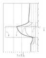
- FIG. 27is a graph of an alternate microwave power profile as a function of time. 158 is an exponential decay function of microwave power and it is an advantage over the fixed power 140 because it accelerates heating when the intima temperature is lowest but slows heating as the intimal temperature approaches its final value for greater control. This has the overall effect of reducing the time necessary for microwave duration and keeps the thermal injury tightly controlled.
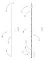
- FIG. 28is a diagram of an antenna particularly suited for renal denervation. It is comprised of two antenna coils, 48 a and 48 b , where coil 48 a is connected to the center conductor 60 of coaxial cable 30 at location 72 and coil 48 b is connected to the outer conductor 62 of coaxial cable 30 at location 70 .
- a tubular extension, 58provides support for coil 48 a .
- Thin wall shrink 50compresses against both coils and keeps them mechanically aligned and it seals against antenna plug 54 and antenna gasket 52 that may be fabricated of silicone rubber to keep the circulating coolant from directly touching coils 48 a and 48 b .
- Coaxial cable 30also has jacket 50 and dielectric 64 . This antenna can be configured to create a single maximum SAR at the “gap” between coil 48 a and 48 b and is suitable for achieving renal denervation.
- FIG. 29is a diagram of an additional antenna embodiment in with coil 48 a and 48 b have non uniform pitch.
- the non uniform pitchhas the effect of narrowing the SAR peak to accommodate the geometry necessary for renal denervation. As described in FIG. 28 , all reference numbers are the same.
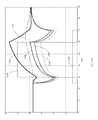
- FIG. 30is a graph of a SAR plot for the antenna in FIG. 28 ( 180 ) and the antenna in FIG. 29 ( 182 ).
- the single peak in SAR ( 180 )may be adjusted in length according to the coil pitch and may be narrowed further by making the coil pitch non uniform ( 182 ).
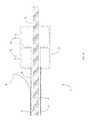
- FIG. 31is a diagram of the antenna described in detail in U.S. Pat. No. 5,300,099.
- Componentsinclude matching capacitor 66 , antenna coil 48 , and tubular extension 58 .
- Shrink tubing 50seals against gasket 52 and antenna plug 54 to keep cooling fluid from directly touching antenna coil 48 .
- Center conductor 60 of coaxial cable 30is connected to matching capacitor 66 at 72 .
- Matching capacitor 66is connected to coil 48 at 68 to form a “tap point” as described in U.S. Pat. No. 5,300,099.
- This antennaproduces a SAR field with two equal maximums and is ideally suited for treating a prostate, kidney, liver, or other organ where a very large volume of thermal injury (may be 20 cubic centimeters or more) is desired and treatment times of 10 to 60 minutes are acceptable.
- a very large volume of thermal injurymay be 20 cubic centimeters or more
- treatment times10 to 60 minutes are acceptable.
- the following adaptations to this basic designmake it more suitable for renal denervation.
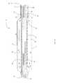
- FIG. 32is a diagram of a modification to the antenna of FIG. 31 to provide two very narrow SAR maximum zones. It has two regions of narrow pitch at each end of coil 48 . Other features are as described above.
- This antennais capable of producing two separated rings of thermal injury and may be particularly useful to accomplish renal denervation as a second narrow ring of thermal injury will make nerve regeneration even more unlikely as nerves would need to “find” each other through two zones of injury.
- FIG. 33is a graph of a SAR plot for the antennas of FIGS. 31 and 32 described above.
- SAR curve 184is for the antenna of FIG. 31 as described in U.S. Pat. No. 5,300,099.
- SAR curve 186is for the modified antenna of FIG. 32 . It can be easily visualized that this modification results in more separated, narrower SAR peaks ideally suited for renal denervation to produce two separate zones of injury to the renal nerves.
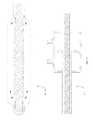
- FIG. 34is a diagram of a further adaptation to the antenna of FIG. 31 as described above and in U.S. Pat. No. 5,300,099. It incorporates a second layer of shrink, 51 , to increase the thickness of dielectric shrink material between coil 48 and coolant occupying region 39 within catheter 10 . This changes the electrical loading due to the near field dielectric and creates an asymmetry in the SAR peaks. For the applications discussed in U.S. Pat. No. 5,300,099 this is undesirable but for renal denervation this can be utilized to emphasize SAR from one element of 48 so much that the SAR contribution from the second element will not produce thermal injury. An antenna configured with this modification will accordingly create a single narrow region of thermal injury that may be of particular advantage for accomplishing renal denervation.
- An additional enhancement of this effectis to narrow the pitch of the proximal winding of antenna coil 48 such that the enhanced SAR produced as described above will be further concentrated along a shorter radiation length.
- FIG. 35is a graph of a SAR plot for the antennas depicted in FIG. 31 ( 184 ) and in FIG. 34 ( 188 ). It can be easily visualized that the distal SAR peak has been minimized to a non-significant level and the essentially single remaining SAR peak has been made narrower. This SAR distribution will accomplish renal denervation in shorter renal arteries than is possible with the unmodified antenna of FIG. 31 as described above and in U.S. Pat. No. 5,300,099.
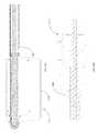
- FIG. 36is a diagram of an alternate antenna embodiment adapted to place the antenna coil in the cooling balloon 40 rather than within the catheter body wall.
- This adaptationwas applied to the antenna shown in FIG. 28 for illustration but may be applied to any other antenna described above.
- Inner body wall 22is sized to create interior region 39 for cooling flow between tubular extension 58 and coaxial cable jacket 59 and the inner surface of inner body wall 22 .
- Center conductor 60 of coaxial cable 30is connected to antenna coil 48 a at connection 72
- outer conductor 62 of coaxial cable 30is connected to coil 48 b at connection 70 as described above, but in this adaptation sealant adhesive 53 is applied to seal the connections and prevent water from entering coaxial cable 30 or the region between inner body wall 22 and antenna shrink 50 where antenna coils 48 a and 48 b are located.
- An additional gasket 52for a total of two (2) gaskets, is configured to seal antenna shrink 50 to inner body wall 22 at both ends of antenna coil 48 a and 48 b .
- Adhesive sealant 53is also applied within tubular extension 58 to also keep coolant out of coaxial cable 30 .
- Coolant ports 44allow coolant to flow from region 41 within balloon 40 and inner region 39 between tubular extension 58 and inner body wall 22 .
- FIG. 37is a more detailed diagram of the device embodied in FIG. 1F , depicting an embodiment of catheter 10 that locates antenna coil 48 within balloon 40 as in FIG. 1F .
- Coolantflows between inner body wall 22 and outer body wall 20 , through spacer 56 , and into interior region 41 formed by balloon 40 as before.
- Antenna coil windings 48 a and 48 bare placed within this region as well, separated only by shrink tubing 50 from coolant 41 within.
- the outer conductor of coaxial cable 30is connected to proximal antenna winding 48 b through connection 70 .
- the inner conductor of coaxial cable 30is connected to distal antenna winding 48 a through connection 72 .
- the end of coaxial cable 30is sealed with potting adhesive 53 to prevent coolant ingress. Coolant flows through ports 44 and between the jacket of coaxial cable 30 and inner body wall 22 within the antenna.
- FIG. 38is a revised diagram of the device embodied in FIG. 1B and scaled to be compatible with the embodiment described in FIG. 37 . It includes the re-scaled inner wall as in FIG. 37 to better illustrate cooling fluid flow. Cooling fluid enters port 26 through tubing or a fluid connector 531 such as a female Luer connector, and enters the input chamber of manifold body 24 . From there, coolant flows through the space between the inner catheter wall 22 and outer catheter wall 20 down to distal portion 16 of microwave antenna carrying catheter 10 . After the coolant circulates through distal portion 16 as described above, it returns through the space between inner catheter wall 22 and coaxial cable 30 and enters the exhaust chamber of manifold body 24 .
- a fluid connector 531such as a female Luer connector
- Coaxial cable 30may exit manifold body 24 or may be terminated with RF connector 529 , such as a male SMA connector, mounted directly on manifold body 24 .
- FIG. 39is a diagram of a tip embodiment that is compatible with a guide wire to allow introduction and positioning with a guide wire instead of or in addition to a guide catheter as may be preferred by certain physicians.
- a tipis sometimes referred to as a “monorail” tip.
- Tip 342connects with balloon 40 and catheter wall 22 and/or catheter wall 20 as before.
- tip 342includes channel 343 through which guide wire 345 may pass. This enables microwave antenna containing catheter 10 to track guide wire 345 previously placed using well adopted procedures.
- Guide wire 345may be retracted past balloon 40 or removed prior to initiating the denervation procedure to avoid interfering with the microwave field or cooling.
- FIG. 40is a diagram of an end-fed antenna embodiment.
- the distal end of distal coil winding 48 ais attached to the center conductor of coaxial cable 30 by interconnect 470 .
- the proximal end of distal coil winding 48 ais unconnected.
- the proximal end of proximal antenna coil winding 48 bis connected to outer the outer conductor of coaxial cable 30 through connection 472 .
- the distal end of proximal coil winding 48 bis unconnected.
- the coaxial cableis sealed using potting adhesive 53 , and additionally potting adhesive may be used to isolate connections 470 and 472 from the coolant.
- Catheter inner and outer wall 22 and 20 , spacer 56 , balloon 40 , tip 42 and coolant ports 44function as described previously.
- FIG. 41Adepicts the entire microwave antenna carrying catheter 510 as fabricated and tested in an exemplary embodiment.
- Catheter 510fits through an off-the-shelf 8 French renal guide catheter.
- Distal portion 516 of catheter 510incorporates the antenna and cooling balloon.
- Middle portion 514 of catheter 510is comprised of the flexible catheter tubing and coaxial cable.
- Proximal portion 512 of catheter 510is comprised of a manifold, strain relief, coolant tubing, and coaxial connector as is illustrated in FIG. 41D .
- Length Lmay be adjusted as needed to provide a convenient working distance but it is desirable to keep it as short as possible to mitigate coaxial cable loss, coolant pressure drop, and coolant temperature warming due to heat absorption along the length of the catheter.
- FIG. 41Bdepicts distal portion 516 of microwave antenna carrying catheter 510 in detail.
- coolantflows between outer catheter wall 520 and inner catheter wall 522 and enters interior chamber 541 of balloon 540 .
- Balloon 540inflates due to coolant pressure and contacts the artery wall (not shown).
- Coolantflows through ports 544 of tip 542 and into the space between inner catheter wall 522 and coaxial cable 530 .
- Coolantreturns to proximal portion 512 of microwave antenna carrying catheter 510 through the region between coaxial cable 530 and inner catheter wall 522 .
- coolantmay flow in the opposite direction as described previously.
- Distal and proximal antenna winding coils 548 a and 548 bare wound about inner catheter wall 520 .
- Thin shrink material 550surrounds antenna coils 548 a and 548 b to isolate these coils from the coolant in interior chamber 541 .
- the center conductor of coaxial cable 530is attached to distal coil 548 a at connection 572 .
- the outer conductor of coaxial cable 530is attached to proximal coil 548 b at connection 570 . These connections are sealed with potting adhesive 553 to prevent fluid ingress.
- FIG. 41Cis an exploded view of distal portion 516 of an exemplary embodiment of microwave antenna carrying catheter 510 including construction details.
- balloon 540is made of Nylon
- shrink material 550is made of polyester
- potting adhesive 553is Loctite 331 .
- balloon 540may be made of other materials, including materials having compliant or blended properties.
- Solderis used to make connections 570 and 572 that connect the proximal and distal antenna coils 548 b and 548 a , respectively (although other means of attachment such as welding may be used in other embodiments).
- Balloon 540has interior chamber 541 as described above.
- FIG. 41Ddepicts a detailed drawing of proximal portion 512 of microwave antenna carrying catheter 510 .
- Catheter inner wall 522is advanced into manifold body 524 and bonded using adhesive fill port 527 .
- Catheter outer wall 520is advanced inside distal end of manifold body 524 and bonded.
- Flexible strain relief 525is placed over catheter tubing where it enters the distal end of manifold body 524 , and supports the tubing during bending so it does not kink.
- Coolantenters manifold body 524 through passage 526 and into the space between inner catheter wall 522 and outer catheter wall 520 . Coolant returns from the space between inner catheter wall 522 and coaxial cable 530 and out through passage 528 as described previously. Alternately, the coolant flow may be reversed.
- Coaxial cable 530is terminated to connector 529 and potting adhesive delivered through port 527 seals and affixes connector 529 to manifold body 524 .
- FIG. 42is a diagram illustrating tissue equivalent phantom containing sheets of Liquid Crystal Temperature sensing film 603 that enables visualization of the temperature field produced by the present invention.
- Specially formulated and cross linked gel 602fills container 601 and mimics dielectric and thermal properties of tissue. Sheets of Liquid Crystal Temperature sensing film, 603 are placed within gel 602 .
- Graticule lines 604are spaced 10 mm apart and are screened directly to Liquid Crystal Temperature sensing film 603 (graticule lines 604 may appear non-square in FIG. 42 due to geometric distortion from the phantom container 601 and/or the camera lens).
- Catheter 510carrying microwave antenna 546 , is advanced into gel 602 adjacent the liquid crystal sensing film 603 .
- Catheter 510is energized with microwave power and provided with circulating cooling fluid in accordance with the techniques described herein, and the resulting temperature field can be viewed on the Liquid Crystal Temperature sensing film, 603 , as rings of color corresponding to isotherms.
- FIG. 42clearly depicts two tightly controlled regions 605 of temperature elevation spaced from balloon 540 by a cooler region 607 that prevents ablation of the renal artery. Additionally, it may be observed that the size of the heated zones 605 is ideal for targeting renal nerves and sparing the artery.
- FIG. 43is a graph of the microwave power, microwave reflected power, coolant temperature, and tissue temperatures captured by temperature sensors placed in the region of a porcine renal artery during microwave renal denervation using the microwave antenna carrying catheter of the present embodiment.
- This temperature fieldproduced the histology sections shown in FIGS. 44A-44D .
- the x-axisis time in seconds.
- the y axisis temperature in degrees C. for the temperature data (curves 142 , 144 , 166 and 148 ) and power in Watts for the forward & reflected power (curves 140 and 168 , respectively).
- Tissue temperature data in the target zoneapproximately 2 mm from the intima, is labeled 148 and reaches a temperature above 80° C.
- Tissue temperature data from a sensor located adjacent the intimais labeled 144 and remains below 40° C.
- Coolant input temperatureis labeled 142 and is substantially below body temperature.
- Coolant outlet temperatureis labeled 166 and is also substantially below body temperature.
- Forward power in Wattsis labeled as 140 .
- Reflected power in Wattsis labeled as 168 .
- FIGS. 44A-44Dare histology slides that demonstrate thermal destruction of renal nerves without any damage to the intima or media of a representative porcine renal artery using the present embodiment in accordance with the present invention.
- FIG. 44Adepicts the intima 96 and media 98 of a porcine renal artery in the upper left region of the picture as treated by the present invention. Both intima 96 and media 98 are viable as evidenced by nitro blue tetrazolium (NBT) positive staining throughout region 105 .
- Line 107has been drawn by pathology to illustrate the boundary between NBT Positive (viable) tissue in region 105 and NBT Negative (ablated) tissue in region 109 . All tissue within region 109 is ablated, including ablated nerves 102 .
- FIG. 44Bdepicts another region of tissue surrounding intima 96 and media 98 of a porcine renal artery as treated by the present invention.
- NBT Positive region 105contains intima 96 and media 98 , as can be observed on the left side of the slide.
- Boundary 107has been drawn as before to separate the NBT positive (viable) tissue in both regions marked 105 from NBT negative (ablated) tissue in region 109 . All tissue within region 109 is ablated.
- FIG. 44Cdepicts another region of tissue surrounding viable intima 96 and media 98 within NBT positive (viable) region 105 .
- Adjacent to region 105is NBT negative (ablated) region 109 .
- Within region 109is an example of an ablated nerve 102 and perineurium. More distant from the artery is NBT positive tissue that is again viable.
- FIG. 44Ddepicts another region of tissue surrounding viable intima 96 and media 98 of a renal artery within NBT positive (viable) region 105 .
- Adjacent to region 105is NBT negative (ablated) region 109 .
- NBT negative (ablated) region 109Within NBT negative (ablated) region 109 is a renal nerve 102 that is also ablated.
- FIG. 44Eis a histology slide depicting viable tissue throughout as evidenced by NBT positive staining. NBT positive (viable) tissue exists throughout and the intima 96 , media 98 , adventitia 100 , and surrounding connective tissue 104 are clearly visible as normal tissue. This slide is useful to compare to the ablated regions.
- FIGS. 45A-45Care computer simulation graphs that illustrate the importance of cooling in accordance with embodiments of the present invention to protect intima and media tissues from thermal injury.
- the x-axisis distance in mm with zero (the origin) being the inner surface of the intima (lumen).
- the y-axisis temperature in degrees C.
- the computed temperature for each discrete computational node (distance from intima)is identified by a circle, and lines 701 are drawn between nodes to interpolate the solution for any value of distance.
- a 6 mm diameter balloonhas been simulated as this is an average renal artery diameter for humans.
- thermal ablation threshold temperature for a 60 second renal nerve ablationis not presently known and is the subject of future research, and temperature varies with time, for illustrative purposes a simplified threshold of 60 degrees C. will be used for ablation based upon anecdotal evidence.
- the tolerance for the intima, media and adventitia of a renal artery for a 60 second exposure to temperature elevationis also not known.
- the threshold value 708 for protectionis established at 50 degrees C.
- the threshold value 703 for ablationis established at 60 degrees C.
- the temperature range sufficient for ablationis marked 704
- temperature for tissue preservationis marked 709
- temperature for which some level of thermal injury can be expectedis marked 706 .
- the ablation radial distanceis marked 702 .
- the range of distance for which safe temperature exposure is maintainedis marked 710 .
- FIG. 45Adepicts simulated temperature 701 achieved at the end of a 60 second ablation procedure with a coolant temperature of 36° C. and power set to 60 Watts.
- the simulated temperature curve 701crosses the 60° C. line 703 at about 0.5 mm (marked 712 ), and again at 4.0 mm (marked 713 ), corresponding to the inner and outer radius of the ablation zone.
- the intima temperatureis at 50° C., and rises very rapidly as distance is increased to 0.5 mm. Accordingly, the intima and media are exposed to a range of temperature (marked 706 ) in excess of 50 C, (threshold 708 ) over a distance 707 , and will likely be thermally injured. This temperature field would be expected to produce an ablation outer radius of 4 mm (marked 702 ) from the intima, but will undesirably heat the intima and media.
- FIG. 45Bdepicts simulated temperature 701 achieved at the end of a 60 second ablation procedure with a coolant temperature of 21° C. and power set to 64 Watts.
- the temperature curve 701crosses the 60° C. line at about 1.0 mm, (marked 712 ), and again at 4.0 mm (marked 713 ).
- the intima temperatureis below 40° C. and the 50° C. threshold is crossed at about 0.5 mm (marked 714 ). Accordingly, this temperature field would be expected to produce an outer ablation radius 702 of 4 mm from the intima as before, but with about 0.5 mm of viable tissue surrounding the intima (marked 710 ).
- FIG. 45Cdepicts simulated temperature achieved at the end of a 60 second ablation procedure with a coolant temperature of 6° C. and power set to 68 Watts.
- the temperature curve 701crosses the 60° C. line ( 703 ) at about 1.4 mm (marked 712 ), and again at 4.0 mm (marked 713 ), as in the simulation of FIG. 45B described above.
- the intima temperatureis maintained at approximately 25° C. and the 50° C. threshold ( 708 ) is not crossed until almost 1.0 mm (marked 714 ).
- this temperature fieldwould be expected to produce an outer ablation radius 702 of 4 mm from the intima as in the previous simulation, but with at least about 1 mm of viable tissue (marked 710 ) surrounding the intima. This will effectively protect intima 96 , media 98 , and adventitia 100 .
- FIGS. 45A-45Cclearly indicate the importance of cooling using coolant that is below body temperature to protect the artery and enable a short duration, high temperature ablation.
- a device and methodare provided to create a thermal lesion in the immediate adjacent surrounding tissue of a bronchus containing nerve trunks which traverse along the outside of both the right and left primary bronchi, so that these nerve trunks are thermally damaged, while protecting the bronchus from injury.
- Thisdisconnects airway smooth muscle and mucus producing glands from the vagus nerve and central nervous system, resulting in a relaxation of the airway smooth muscle and a reduction in mucus production. Accordingly, airway obstruction due to disease such as COPD and asthma is reduced.
- the present inventionhas the advantage of protecting the intervening bronchial tissue and not requiring the energy emitter to be electrically in contact with the tissue. An additional advantage is the potential for a shortened procedure time and easier procedure.
- FIGS. 46A-46Eare diagrams illustrating microwave antenna-carrying catheter 1010 according to an embodiment of the present invention.
- catheter 1010includes proximal portion 1012 , middle portion 1014 , and distal portion 1016 .
- FIG. 46Bis an enlarged view of proximal portion 1012 of catheter 1010 .
- Catheter 1010includes outer body wall 1020 and inner body wall 1022 , between which a space is defined for the flow of coolant.
- coolant intake/exhaust structure 1024is provided, with walls configured to provide a coolant input port 1026 that communicates with the space between outer body wall 1020 and inner body wall 1022 of catheter 1010 , and also to provide a coolant output port 1028 that communicates with an interior of catheter 1010 formed by coaxial cable 1030 and the inside inner body wall 1022 .
- Coaxial cable 1030is provided to the interior of catheter 1010 inside inner body wall 1022 , is coupled to a microwave antenna 1046 ( FIG. 46D ) at distal portion 1016 ( FIG. 46A ) of catheter 1010 , and is coupled to a microwave generator (not shown) to supply power to the microwave antenna via coaxial cable 1030 .
- a balloon on the distal portioninflates asymmetrically to achieve targeting of the bronchus nerve trunk.
- FIG. 46Cis an enlarged view of middle portion 1014 of catheter 1010 , showing outer body wall 1020 , inner body wall 1022 , coaxial cable 1030 , and interior region for coolant to flow within catheter body walls 1039 .
- These componentsmake up the flexible shaft of catheter 1010 that is able to be guided into the bronchus of a patient via the trachea, for example.
- the lengthis suitable to conveniently be inserted into the mouth and reach the bronchus via the trachea or may be adjusted to accommodate other insertion locations.
- the catheter shaft 1014includes a torquable attribute to enable alignment of the balloon with the target nerve trunk. This attribute may be an external braid, torquable coaxial cable, or a combination of these to ensure proper alignment to the target nerve trunk.
- FIG. 46Dis an enlarged view of distal portion 1016 of catheter 1010 .
- balloon 1040is attached to outer body wall 1020 of catheter 1010 to form interior region 1041 for cooling fluid to inflate balloon 1040 asymmetrically to achieve directionality to target the nerve trunk. Cooling fluid pressure is responsible for inflation of the balloon and may be controlled by an external pressure regulator (not shown) incorporated into the tubing or control unit connected to catheter 1010 .
- Balloon 1040is attached to tip 1042 at a distal end of distal portion 1016 of catheter 1010 .
- Return ports 1044are provided in inner body wall 1022 of catheter 1010 to allow cooling fluid to exit balloon 1040 and flow in a return path toward proximal portion 1012 ( FIG.
- FIGS. 46BAdditional ports are provided in coaxial cable spacer 1056 so that coolant may continue to flow in a return path toward the proximal portion 1012 ( FIG. 46B ) of catheter 1010 in the space formed between the inner body wall 1022 and coaxial cable 1030 .
- Microwave antenna 1046is coupled to coaxial cable 1030 at distal portion 1016 of catheter 1010 , with windings 1048 configured to form a microwave radiator.
- Thin wall shrink tubing 1050is placed around antenna 1046 to isolate it from coolant flowing within space 1039 . Additional details on various antenna embodiments are depicted in FIGS.
- a temperature sensor 1032is positioned on the surface of balloon 1040 to monitor the temperature of the intima 1096 during the treatment. The temperature reading may be used to control treatment parameters and/or to ensure safety.
- FIG. 46E and FIG. 47depict an embodiment of catheter 1010 without a temperature sensor 1032 .
- this sensoris not necessary and it simplifies 1010 and also eliminates the possibility of non-uniform heat transfer between mucosa at the intima 1096 of bronchus 1094 and coolant within balloon 1041 .
- FIG. 46Fdepicts an embodiment of catheter 1010 that locates antenna coil 1048 within balloon 1040 rather than within the catheter body wall. Coolant flows between inner body wall 1022 and outer body wall 1020 , through spacer 1056 , and into interior region 1041 formed by balloon 1040 as before. However, antenna coil 1048 is placed within this region as well, separated only by shrink tubing 1050 from coolant within 1041 . Coolant then flows through ports 1044 as before but in this embodiment coolant will flow between coaxial cable jacket 1030 and inner body wall 1022 within the antenna.
- Specific antenna adaptations to permit this flow of coolant and seal coolant from interior regions of coaxial cable 30are diagramed in FIG. 36 as described above with respect to the renal denervation example.
- FIG. 47is a diagram of more details of distal portion 1016 of catheter 1010 including cross sectional views of the balloon 1040 , of the coaxial cable spacer 1056 , and of the shaft of catheter 1010 .
- Cross section 1074corresponds to section A-A and includes balloon 1040 , the region 1041 for coolant to flow inside the balloon 1040 , coaxial cable 1030 , antenna coil 1048 , antenna shrink tubing 1050 , and a region 1039 within which coolant flows between the antenna and inner body wall 1022 .
- the outer body wall 1020does not extend into the balloon beyond spacer 1056 .
- Cross section 1076corresponds to section B-B and includes coaxial cable spacer 1056 containing ports 1044 for coolant to flow in the return path, inner body wall 1022 , outer body wall 1020 , an inner region 1039 for coolant to flow, and balloon 1040 as bonded to outer body wall 1020 .
- Cross section 1078corresponds to section C-C and includes coaxial cable 1030 , inner body wall 1022 , outer body wall 1020 , and regions 1039 for coolant to flow within the catheter body walls 1020 and 1022 .
- a computer simulation of operation of a microwave catheter for pulmonary denervationwas performed to illustrate the temperature profile that could be expected to be achieved.
- the simulationwas configured with the following parameters and assumptions:
- This equationis an energy balance that simply states the sum of conductive heat flow minus convective heat due to blood flow plus heat generation from an external source (microwave) plus metabolic heating gives rise to temperature elevation.
- the metabolic component Qm ⁇ Qcan be neglected.
- FIG. 48Ais a graph of a representative simulation as described above as a function of time.
- coolant flow at a temperature of 4° C.1142
- microwave power1140
- coolant flow 1142is maintained at 6° C. for 20 seconds.
- Simulated temperatures corresponding to mucosa on the preferentially hot side 1144 and cool side 1148 , target tissue temperature on the preferentially hot side 1146 and cool side 1150 , and nearby fat tissue 1151are shown.
- Thermal injurydepends on the entire thermal history (time & temperature) and depends upon the specific tissue. However, it can be appreciated that this simulation depicts a greater than 20° C. temperature difference between the target tissue 1146 (nerves within the layer of tissue surrounding the cartilage) and the mucosa 1144 .
- FIG. 48Bis a graph illustrating the temperature profile achieved by the computer simulation described above and plotted as a function of time in FIG. 48A at a specific time so that the temperature distribution as a function of distance from the mucosa may be visualized.
- Tissue temperature on the preferentially hot side 1160is plotted against position in units of mm so that it can be clearly seen that the maximum temperature (of about 53° C.) occurs at a distance of about 2.0 mm (e.g., 1.6 mm) from the intima, which is the location of the target nerves for pulmonary denervation, while the temperature within 0.5 mm of the smooth muscle layer is held below about 43° C. and temperature of the mucosa is held below 40° C.
- a representative thermal injury threshold for a sample treatment durationis depicted by line 1162 and basal body temperature is indicated by line 1164 .
- tissue located between about 1.5 mm and about 2.5 mmwill be irreversibly thermally injured. It must be understood that thermal injury is the result of temperature AND time and a fixed threshold value of 50° C. is used here to illustrate the concept. It can be appreciated that the temperature field may be adjusted as necessary to achieve thermal injury to the specific target tissue (nerve trunk) once the specific tissue has been thermally characterized.
- the targeted pulmonary nerve trunkis located where the highest temperature is achieved.
- the very steep temperature gradient between the mucosa and the maximum temperature regionallows pulmonary nerves to be damaged sufficiently to effectively achieve pulmonary denervation therapy, while protecting the mucosa, smooth muscle, and cartilage of the bronchus from damage. Further, the decay in temperature beyond 2.5 mm is sufficient to ensure no damage to adjacent structures.
- the specific area in which maximum temperatures are achieved, and the temperature values achieved,can be adjusted by adjusting parameters such as power provided to the microwave antenna as a function of time, coolant temperature as a function of time, microwave duration, volume of coolant provided around the microwave antenna, and others.
- FIG. 48Cdepicts an extension of the 1-dimensional simulation to a 2-dimensional contour plot cross section within the treatment zone.
- the catheter 1010is placed in the middle and the first contour line represents mucosa temperature ( 1144 ).
- the maximum temperature, 1146is achieved directly above catheter 1010 . This is the region of thermal injury.
- a maximum temperature 1150no much above basal temperature and a mucosal temperature 1148 a bit lower than 1144 .
- Adjacent tissue 1151is below thermal damage.
- FIG. 48Cis a mesh blot of the temperature field in FIG. 48C for improved visualization.
- the highest temperatureis the highest “elevation” on the plot and is marked 1146 .
- FIG. 48Ddepicts a surface plot of the 2-dimensional temperature field to provide another visualization. Maximum temperature is labeled 1146 and the cooled mucosa tissue temperature is labeled 1144 .
- FIG. 49Ais a diagram of a guide catheter 1080 .
- Guide catheter 1080includes a tip 1084 , a central shaft 1082 , and a manifold 1086 , and is sized to accommodate the pulmonary device.
- FIG. 49Bis a diagram of catheter 1010 placed within guide catheter 1080 .
- Distal portion 1016 of catheter 1010extends just beyond tip 1084 when the proximal end 1012 is conveniently close to manifold 1086 .
- FIG. 49Cis a diagram of the distal portion 1016 of catheter 1010 exiting guide catheter tip 1084 .
- Balloon 1040is shown inflated asymmetrically to provide the desired temperature field.
- FIG. 49Dis a diagram of the proximal portion 1012 of catheter 1010 entering manifold 1086 of guide catheter 1080 .
- FIG. 50is a cross section of a bronchus just below the trachea.
- tissue layersFour “tissue layers” are shown: The mucosa, 1096 , the smooth muscle layer, 1098 , the cartilage layer, 1100 , and the surrounding tissue layer 1104 containing the targeted nerve trunk 1102 . More distant tissue 1105 surrounds the bronchus.
- the airway lumenis 1095 .
- FIG. 51Ais a diagram of the in-vivo placement of catheter 1010 using guide catheter 1080 within a human body.
- guide catheter 1080is introduced into the mouth of the patient and advanced into the desired bronchus 1094 via the trachea 1092 under guidance as known in the art.
- Microwave antenna carrying catheter 1010is introduced into guide catheter 1080 by manifold 1086 and advanced until deflated balloon 1040 and microwave antenna 1046 are fully extended beyond tip 1084 of guide catheter 1080 and positioned within the desired bronchus 1094 in the region where the target nerve trunk runs along the bronchus. The position is confirmed by imagine prior to initiating the treatment algorithm.
- FIG. 51Bis an exploded diagram of the in-vivo placement of balloon 1040 and antenna 1046 within bronchus 1094 .
- Balloon 1040is inflated by circulating cooling fluid to contact mucosa 1096 of bronchus 1094 .
- the smooth muscle layeris depicted by 1098 , cartilage by 1100 , and surrounding tissue containing the target nerve trunk by 1104 .
- the nerve trunk, 1102is not shown in this drawing.
- cooling fluid generally below a normal basal body temperature of 37° C.is circulated through the space 1039 between outer body wall 1020 and inner body wall 1022 to interior region 1041 of balloon 1040 , so that balloon 1040 is asymmetrically inflated to be in contact with the mucosa wall of the bronchus.
- Proper inflation of balloon 1040may be confirmed by CT or other imaging.
- microwave poweris then initiated according to the treatment algorithm and is supplied by a microwave generator to coaxial cable 1030 , which feeds microwave antenna 1046 and causes microwave energy to be emitted preferentially at distal portion 1016 of catheter 1010 within bronchus 1094 .
- the microwave energy emitted by microwave antenna 1046causes tissue temperature to increase in the area surrounding microwave antenna 1046 , while cooling fluid circulating through balloon 1040 cools the tissue immediately surrounding catheter 1010 .
- the net resultis that the tissue immediately surrounding distal portion 1016 of catheter 1010 (such as the mucosa, smooth muscle and cartilage of the bronchus) is maintained at a temperature where thermal damage will not occur, while tissue surrounding distal portion 1016 of catheter 1010 that is spaced some distance from inflated balloon 1040 (such as the surrounding tissue 1104 containing nerve trunk 1102 ) is heated to a temperature sufficient to cause thermal damage to the tissue.
- FIG. 52Ais a diagram illustrating a cross section of catheter 1010 placed in the bronchus of a patient during pulmonary denervation.
- Microwave antenna 1046is shown off set from the center of balloon 1040 placed within bronchus 1094 .
- the mucosa 1096is in contact with balloon 1040 such that heat transfer between mucosa 1096 and the cooling fluid in the interior 1041 of balloon may occur to keep mucosa 1096 cooled and protected from thermal injury—this concept can be referred to as “thermal contact” between the cooling fluid and mucosa 1096 , through the wall of balloon 1040 .
- Smooth muscle layer 1098 and cartilage layer 1100surrounds mucosa 1096 and is cooled by heat transfer to mucosa 1096 .
- tissue layer 1104 containing target nerve trunk 1102Surrounding tissue layer 1104 containing target nerve trunk 1102 is exposed to the highest temperature 1146 at the location of nerve trunk 1102 and results in thermal ablation of nerve trunk 1102 . More distant surrounding tissue 1104 does not receive sufficient heat to cause thermal damage, nor does other tissue maintained close to basal temperature 1150 .
- FIG. 52Bis another simulation contour plot as described above for FIG. 48C but here it is scaled to match the size of the bronchus cross section so that the precise targeting of nerve trunk 1102 by temperature field maximum 1146 can be appreciated.
- the maximum temperature contour lines 1148coincide with nerve trunk 1102 . It can also be appreciated that the mucosa 1144 and 1148 , smooth muscle 1098 and cartilage layer 1100 are located on cooler contour lines and therefore do not experience thermal damage. Temperature at distant tissue 1150 is maintained very near basal temperature and is undamaged.
- FIG. 53is a flowchart that depicts steps for the placement of the microwave carrying catheter 1010 within the bronchus 1094 to accomplish pulmonary denervation in accordance with the present invention.
- the patientis prepped as is well known in the art and the trachea is accessed via the mouth.
- a guide catheteris inserted according to FIG. 51A and advanced into the trachea 1092 and advanced until the distal tip 1084 of guide catheter 1080 is positioned within the desired bronchus 1094 using techniques known in the art. This is commonly accomplished with the use of CT guidance and the proper position of tip 1084 within bronchus 1094 may also be verified by CT guidance or other imaging.
- Microwave antenna containing catheter 1010is advanced into guide catheter 1080 and positioned such that the entire balloon 1040 is contained within bronchus 1094 and the antenna coil windings 1048 are placed adjacent to the desired nerve trunk for pulmonary denervation.
- the catheteris rotated to angularly orient the preferentially heating to the target nerve trunk. Verification of the location and rotation of balloon 1040 is critical to successful pulmonary denervation so it is checked and repositioned as necessary. Once properly located, pulmonary denervation is initiated according to the procedure shown in FIG. 25 and described in detail above with respect to the renal denervation example. Proper inflation of balloon 1040 by cooling fluid within interior 1041 is also verified before initiating microwave power 1140 .
- the balloon 40will deflate when cooling flow is discontinued.
- the microwave carrying catheter 1010may then be removed from guide catheter using techniques known in the art.
- the other bronchusis treated as described above if necessary, and then the catheter 1010 may be removed.
- the last stepsare to remove guide catheter 1080 in accordance with known techniques.
- the patientis then monitored as is known in the art.
- Catheter 1010 for pulmonary denervation via the bronchusis similar in a number of respects to the catheter embodiments described previously for performing renal denervation via the renal artery. As such, many of the characteristics, configurations and principles of the catheter embodiments described previously, such as with respect to FIGS. 37-45C for example, are applicable to catheter 1010 for performing pulmonary denervation, and may be incorporated in any combination thereof into the design and/or operation of catheter 1010 for pulmonary denervation.
- a cathetersuch as a catheter configured similar to catheter 1010 described above in some embodiments
- a catheterin a procedure that involves energizing the microwave antenna while circulating cooling fluid so as to target a first region of tissue on one side of the body lumen in which the catheter is inserted, rotating and optionally longitudinally shifting the catheter so that the angular orientation and optionally the position of the catheter is changed, and energizing the microwave antenna again while circulating cooling fluid so as to target a second region of tissue on a second side of the body lumen in which the catheter is inserted.
- the overall tissue region ablated by the series of energizationsmay be a circumferential (i.e., generally donut-shaped) lesion surrounding the body lumen, or may be a series of lesions that form a target pattern or that are spaced from one another to achieve a desired extent of ablation of tissue where targeted nerves are located.
- a microwave antenna carrying catheteris employed to deliver the energy to create the lesion, and cooling fluid is circulated around the microwave antenna in thermal contact with the wall of the body lumen to preserve the tissue adjacent to and forming the wall of the body lumen.
- Specific examples for renal denervation and pulmonary denervationare disclosed.
- Denervation according to similar principlesmay be performed with a similar device and/or method in other body locations, including but not limited to the pulmonary artery and branches thereof, pulmonary veins including those near the right atrium, the entire pulmonary tree including the trachea, bronchus, and smaller branches deeper in the lung, the esophagus, the carotid artery, and others, which is expected to provide various beneficial effects to patients.
Landscapes
- Health & Medical Sciences (AREA)
- Surgery (AREA)
- Life Sciences & Earth Sciences (AREA)
- Biomedical Technology (AREA)
- Medical Informatics (AREA)
- Nuclear Medicine, Radiotherapy & Molecular Imaging (AREA)
- Electromagnetism (AREA)
- Engineering & Computer Science (AREA)
- Physics & Mathematics (AREA)
- Heart & Thoracic Surgery (AREA)
- Otolaryngology (AREA)
- Molecular Biology (AREA)
- Animal Behavior & Ethology (AREA)
- General Health & Medical Sciences (AREA)
- Public Health (AREA)
- Veterinary Medicine (AREA)
- Surgical Instruments (AREA)
Abstract
Description
- Published thermal physical properties were used for artery, fat, blood and nerves
- Published complex dielectric properties (conductivity, permittivity) were used for artery and fat
- Published data was used for anatomical structure (7 mm diameter renal artery) and nerve location
- Microwave emitter geometry, specific absorption rate (SAR) field and heat transfer coefficient were modeled
- The simulation space begins at the catheter/renal artery wall interface, and is modeled as a 1-dimensional model and can be extended to 2 dimensions because of symmetry.
| tk1 = 0.476 | for artery |
| tk3 = 0.209 | for fat; Holmes et. al. (tissue radius > OD artery) |
| rocartery = 3.9e+6 | for artery |
| rocbl = 3.9e+6 | for blood |
| rocfat = 3.2e+6 | for fat |
| perf1 = 0.003 | for in-vivo simulations, 0.0 for phantom |
- i. e′=51.7 for artery
- ii. e″=18.0 for artery
- iii. e′=12.9 for fat
- iv. e″=4.13 for fat
- Published and estimated thermal physical properties were used for smooth muscle, fat, blood and nerves
- Published and estimated complex dielectric properties (conductivity, permittivity) were used for smooth muscle, fat and other anatomical structure.
- Microwave emitter geometry, specific absorption rate (SAR) field and heat transfer coefficient were modeled
- The simulation space begins at the catheter/mucosa wall interface, and is modeled as a two 1-dimensional models and extended to 2 dimensions by rotational interpolation between the preferentially hot side and the cool side.
Claims (22)
Priority Applications (4)
| Application Number | Priority Date | Filing Date | Title |
|---|---|---|---|
| US14/032,013US9333035B2 (en) | 2012-09-19 | 2013-09-19 | Cooled microwave denervation |
| US15/068,252US10092352B2 (en) | 2012-09-19 | 2016-03-11 | Cooled microwave denervation |
| US16/153,205US11786302B2 (en) | 2012-09-19 | 2018-10-05 | Cooled microwave denervation |
| US18/468,677US20240000506A1 (en) | 2012-09-19 | 2023-09-15 | Cooled microwave pulmonary denervation |
Applications Claiming Priority (3)
| Application Number | Priority Date | Filing Date | Title |
|---|---|---|---|
| US201261703101P | 2012-09-19 | 2012-09-19 | |
| US201261734419P | 2012-12-07 | 2012-12-07 | |
| US14/032,013US9333035B2 (en) | 2012-09-19 | 2013-09-19 | Cooled microwave denervation |
Related Child Applications (1)
| Application Number | Title | Priority Date | Filing Date |
|---|---|---|---|
| US15/068,252DivisionUS10092352B2 (en) | 2012-09-19 | 2016-03-11 | Cooled microwave denervation |
Publications (2)
| Publication Number | Publication Date |
|---|---|
| US20140081254A1 US20140081254A1 (en) | 2014-03-20 |
| US9333035B2true US9333035B2 (en) | 2016-05-10 |
Family
ID=50275220
Family Applications (4)
| Application Number | Title | Priority Date | Filing Date |
|---|---|---|---|
| US14/032,013Active - Reinstated2033-12-20US9333035B2 (en) | 2012-09-19 | 2013-09-19 | Cooled microwave denervation |
| US15/068,252Active - ReinstatedUS10092352B2 (en) | 2012-09-19 | 2016-03-11 | Cooled microwave denervation |
| US16/153,205Active2036-09-20US11786302B2 (en) | 2012-09-19 | 2018-10-05 | Cooled microwave denervation |
| US18/468,677PendingUS20240000506A1 (en) | 2012-09-19 | 2023-09-15 | Cooled microwave pulmonary denervation |
Family Applications After (3)
| Application Number | Title | Priority Date | Filing Date |
|---|---|---|---|
| US15/068,252Active - ReinstatedUS10092352B2 (en) | 2012-09-19 | 2016-03-11 | Cooled microwave denervation |
| US16/153,205Active2036-09-20US11786302B2 (en) | 2012-09-19 | 2018-10-05 | Cooled microwave denervation |
| US18/468,677PendingUS20240000506A1 (en) | 2012-09-19 | 2023-09-15 | Cooled microwave pulmonary denervation |
Country Status (2)
| Country | Link |
|---|---|
| US (4) | US9333035B2 (en) |
| WO (1) | WO2014047355A1 (en) |
Cited By (13)
| Publication number | Priority date | Publication date | Assignee | Title |
|---|---|---|---|---|
| US10076384B2 (en) | 2013-03-08 | 2018-09-18 | Symple Surgical, Inc. | Balloon catheter apparatus with microwave emitter |
| US10092352B2 (en) | 2012-09-19 | 2018-10-09 | Denervx LLC | Cooled microwave denervation |
| US10182865B2 (en) | 2010-10-25 | 2019-01-22 | Medtronic Ardian Luxembourg S.A.R.L. | Microwave catheter apparatuses, systems, and methods for renal neuromodulation |
| US11197716B2 (en) | 2014-04-14 | 2021-12-14 | Recor Medical, Inc. | Monitoring nerve activity |
| US11642061B2 (en) | 2015-07-29 | 2023-05-09 | Recor Medical, Inc. | Intraluminal microneurography denervation probe with radio frequency ablation |
| US11998266B2 (en) | 2009-10-12 | 2024-06-04 | Otsuka Medical Devices Co., Ltd | Intravascular energy delivery |
| US12076033B2 (en) | 2006-05-19 | 2024-09-03 | Recor Medical, Inc. | Ablation device with optimized input power profile and method of using the same |
| US12102845B2 (en) | 2013-03-14 | 2024-10-01 | Recor Medical, Inc. | Ultrasound-based neuromodulation system |
| US12133765B2 (en) | 2014-11-05 | 2024-11-05 | Otsuka Medical Devices Co., Ltd. | Systems and methods for real-time tracking of a target tissue using imaging before and during therapy delivery |
| US12274833B2 (en) | 2009-10-30 | 2025-04-15 | Recor Medical, Inc. | Method and apparatus for treatment of hypertension through percutaneous ultrasound renal denervation |
| US12350050B2 (en) | 2014-04-14 | 2025-07-08 | Recor Medical, Inc. | Intraluminal microneurography probes and related systems and methods |
| US12419662B2 (en) | 2021-02-19 | 2025-09-23 | Otsuka Medical Devices Co., Ltd. | Selectively insulated ultrasound transducers |
| US12440165B2 (en) | 2022-07-28 | 2025-10-14 | Otsuka Medical Devices Co., Ltd. | Catheter for neural measurements and treatment and related systems and methods |
Families Citing this family (13)
| Publication number | Priority date | Publication date | Assignee | Title |
|---|---|---|---|---|
| JP6441679B2 (en) | 2011-12-09 | 2018-12-19 | メタベンション インコーポレイテッド | Therapeutic neuromodulation of the liver system |
| AU2014274903B2 (en) | 2013-06-05 | 2019-03-07 | Medtronic Ireland Manufacturing Unlimited Company | Modulation of targeted nerve fibers |
| DE102014117693A1 (en) | 2013-12-06 | 2015-06-11 | Topinox Sarl | Method for detecting an influence of microwaves on a measured value of a temperature sensor, cooking appliance and core temperature probe |
| WO2016040056A1 (en)* | 2014-09-10 | 2016-03-17 | Symple Surgical Inc. | Balloon catheter apparatus with microwave emitter |
| CA2969129A1 (en) | 2014-12-03 | 2016-06-09 | Metavention, Inc. | Systems and methods for modulating nerves or other tissue |
| US11344365B2 (en) | 2016-01-05 | 2022-05-31 | Cardiofocus, Inc. | Ablation system with automated sweeping ablation energy element |
| US10524859B2 (en) | 2016-06-07 | 2020-01-07 | Metavention, Inc. | Therapeutic tissue modulation devices and methods |
| WO2018140816A1 (en)* | 2017-01-26 | 2018-08-02 | Broncus Medical Inc. | Bronchoscopic-based microwave ablation system and method |
| US11058489B2 (en)* | 2017-02-10 | 2021-07-13 | Covidien Lp | Devices, systems, and methods for a microwave ablation procedure |
| EP3740147B1 (en) | 2018-01-15 | 2024-03-27 | Cardiofocus, Inc. | Ablation system with automated ablation energy element |
| US20200305974A1 (en)* | 2019-03-25 | 2020-10-01 | Covidien Lp | Pulmonary denervation with bronchial-centered dielectric heating element |
| WO2021026471A2 (en)* | 2019-08-07 | 2021-02-11 | Biocompatibles Uk Limited | Microwave ablation probe |
| DE102020129157A1 (en) | 2020-11-05 | 2022-05-05 | Lavenir Bioscience Ag | Device for removing at least one object or an agglomeration of objects from the skin |
Citations (128)
| Publication number | Priority date | Publication date | Assignee | Title |
|---|---|---|---|---|
| US5304214A (en) | 1992-01-21 | 1994-04-19 | Med Institute, Inc. | Transurethral ablation catheter |
| US5348554A (en)* | 1992-12-01 | 1994-09-20 | Cardiac Pathways Corporation | Catheter for RF ablation with cooled electrode |
| US5620480A (en) | 1992-03-06 | 1997-04-15 | Urologix, Inc. | Method for treating benign prostatic hyperplasia with thermal therapy |
| US5649973A (en) | 1992-11-13 | 1997-07-22 | Dornier Medical Systems, Inc. | Thermotherapy method with tissue cooling |
| US5979454A (en) | 1995-05-15 | 1999-11-09 | The Regents Of The University Of California | Method and apparatus for causing rapid and deep spatially selective coagulation during thermally mediated therapeutic procedures |
| US5987360A (en) | 1996-05-03 | 1999-11-16 | Urologix, Inc. | Axial preferential thermal therapy |
| US6047216A (en) | 1996-04-17 | 2000-04-04 | The United States Of America Represented By The Administrator Of The National Aeronautics And Space Administration | Endothelium preserving microwave treatment for atherosclerosis |
| US6056745A (en)* | 1994-06-27 | 2000-05-02 | Ep Technologies, Inc. | Systems and methods for obtaining desired lesion characteristics while ablating body tissue |
| US6106518A (en) | 1998-04-09 | 2000-08-22 | Cryocath Technologies, Inc. | Variable geometry tip for a cryosurgical ablation device |
| US6122551A (en) | 1998-12-11 | 2000-09-19 | Urologix, Inc. | Method of controlling thermal therapy |
| US6223085B1 (en)* | 1997-05-06 | 2001-04-24 | Urologix, Inc. | Device and method for preventing restenosis |
| US6272384B1 (en) | 1999-05-27 | 2001-08-07 | Urologix, Inc. | Microwave therapy apparatus |
| US6283988B1 (en) | 1997-04-07 | 2001-09-04 | Broncus Technologies, Inc. | Bronchial stenter having expandable electrodes |
| US6283959B1 (en) | 1999-08-23 | 2001-09-04 | Cyrocath Technologies, Inc. | Endovascular cryotreatment catheter |
| US6289249B1 (en) | 1996-04-17 | 2001-09-11 | The United States Of America As Represented By The Administrator Of The National Aeronautics And Space Administration | Transcatheter microwave antenna |
| US20020087208A1 (en)* | 1997-12-03 | 2002-07-04 | Scimed Life Systems, Inc. | Devices and methods for creating lesions in endocardial and surrounding tissue to isolate focal arrhythmia substrates |
| US6427089B1 (en) | 1999-02-19 | 2002-07-30 | Edward W. Knowlton | Stomach treatment apparatus and method |
| US6514249B1 (en)* | 1997-07-08 | 2003-02-04 | Atrionix, Inc. | Positioning system and method for orienting an ablation element within a pulmonary vein ostium |
| US20030055471A1 (en)* | 2000-04-13 | 2003-03-20 | Fenn Alan J. | Thermotherapy method for treatment and prevention of cancer in male and female patients and cosmetic ablation of tissue |
| US20030060813A1 (en) | 2001-09-22 | 2003-03-27 | Loeb Marvin P. | Devices and methods for safely shrinking tissues surrounding a duct, hollow organ or body cavity |
| US6740108B1 (en) | 2001-04-05 | 2004-05-25 | Urologix, Inc. | Thermal treatment catheter having preferential asymmetrical heating pattern |
| US6807446B2 (en)* | 2002-09-03 | 2004-10-19 | Celsion Corporation | Monopole phased array thermotherapy applicator for deep tumor therapy |
| US6918869B2 (en) | 2002-12-02 | 2005-07-19 | Scimed Life Systems | System for administering a combination of therapies to a body lumen |
| US20050228370A1 (en) | 2004-04-12 | 2005-10-13 | Fred Sterzer | Balloon catheter designs which incorporate an antenna cooperatively situated with respect to an external balloon surface for use in treating diseased tissue of a patient |
| US20050249667A1 (en) | 2004-03-24 | 2005-11-10 | Tuszynski Jack A | Process for treating a biological organism |
| US20050288730A1 (en) | 2002-04-08 | 2005-12-29 | Mark Deem | Methods and apparatus for renal neuromodulation |
| US20060041277A1 (en) | 2002-04-08 | 2006-02-23 | Mark Deem | Methods and apparatus for renal neuromodulation |
| US20060111704A1 (en) | 2004-11-22 | 2006-05-25 | Rox Medical, Inc. | Devices, systems, and methods for energy assisted arterio-venous fistula creation |
| US7052508B2 (en) | 1999-10-07 | 2006-05-30 | Innercool Therapies, Inc. | Inflatable heat transfer apparatus |
| US7081112B2 (en) | 1999-02-24 | 2006-07-25 | Cryovascular Systems, Inc. | Cryogenically enhanced intravascular interventions |
| US7097641B1 (en) | 1999-12-09 | 2006-08-29 | Cryocath Technologies Inc. | Catheter with cryogenic and heating ablation |
| US7132439B2 (en) | 2002-05-13 | 2006-11-07 | Icagen, Inc. | Bis-benzimidazoles and related compounds as potassium channel modulators |
| US7162303B2 (en) | 2002-04-08 | 2007-01-09 | Ardian, Inc. | Renal nerve stimulation method and apparatus for treatment of patients |
| US20070129720A1 (en) | 2002-04-08 | 2007-06-07 | Ardian, Inc. | Methods and apparatus for performing a non-continuous circumferential treatment of a body lumen |
| US20070142879A1 (en) | 2005-12-20 | 2007-06-21 | The Cleveland Clinic Foundation | Apparatus and method for modulating the baroreflex system |
| US20070203551A1 (en) | 2005-07-01 | 2007-08-30 | Microsulis Limited | Radiation applicator and method of radiating tissue |
| US7311703B2 (en) | 2003-07-18 | 2007-12-25 | Vivant Medical, Inc. | Devices and methods for cooling microwave antennas |
| US20080215043A1 (en) | 2005-04-29 | 2008-09-04 | Cryocath Technologies Inc. | Wide area ablation of myocardial tissue |
| US20080255642A1 (en) | 2006-06-28 | 2008-10-16 | Ardian, Inc. | Methods and systems for thermally-induced renal neuromodulation |
| US20090024195A1 (en) | 2005-09-12 | 2009-01-22 | The Cleveland Clinic Foundation | Method and apparatus for renal neuromodulation |
| US20090171157A1 (en) | 2001-12-14 | 2009-07-02 | The Regents Of The University Of California | Catheter based balloon for therapy modification and positioning of tissue |
| US7617005B2 (en) | 2002-04-08 | 2009-11-10 | Ardian, Inc. | Methods and apparatus for thermally-induced renal neuromodulation |
| US7620451B2 (en) | 2005-12-29 | 2009-11-17 | Ardian, Inc. | Methods and apparatus for pulsed electric field neuromodulation via an intra-to-extravascular approach |
| US20100168731A1 (en) | 2008-12-31 | 2010-07-01 | Ardian, Inc. | Apparatus, systems, and methods for achieving intravascular, thermally-induced renal neuromodulation |
| US20100174282A1 (en) | 2002-04-08 | 2010-07-08 | Ardian, Inc. | Apparatus for thermal modulation of nerves contributing to renal function |
| US7756583B2 (en) | 2002-04-08 | 2010-07-13 | Ardian, Inc. | Methods and apparatus for intravascularly-induced neuromodulation |
| US20100262137A1 (en) | 2009-04-09 | 2010-10-14 | Neil Nye | Cooled antenna for device insertable into a body |
| US7840271B2 (en) | 2000-09-27 | 2010-11-23 | Cvrx, Inc. | Stimulus regimens for cardiovascular reflex control |
| US7853333B2 (en) | 2002-04-08 | 2010-12-14 | Ardian, Inc. | Methods and apparatus for multi-vessel renal neuromodulation |
| US7925352B2 (en) | 2008-03-27 | 2011-04-12 | Synecor Llc | System and method for transvascularly stimulating contents of the carotid sheath |
| US20110092781A1 (en) | 2009-10-12 | 2011-04-21 | Michael Gertner | Energetic modulation of nerves |
| US7937143B2 (en) | 2004-11-02 | 2011-05-03 | Ardian, Inc. | Methods and apparatus for inducing controlled renal neuromodulation |
| US20110184337A1 (en) | 2010-01-26 | 2011-07-28 | Evans Michael A | Methods and devices for denervation |
| US20110200171A1 (en) | 2010-01-19 | 2011-08-18 | Ardian, Inc. | Methods and apparatus for renal neuromodulation via stereotactic radiotherapy |
| US20110257562A1 (en) | 2010-04-01 | 2011-10-20 | Alan Schaer | Method and apparatus employing ultrasound energy to remodulate vascular nerves |
| US20110257523A1 (en) | 2010-04-14 | 2011-10-20 | Roger Hastings | Focused ultrasonic renal denervation |
| US20110264116A1 (en) | 2009-12-31 | 2011-10-27 | Gordon Kocur | Compressive Denervation Apparatus for Innervated Renal Vasculature |
| US20110264086A1 (en) | 2010-04-14 | 2011-10-27 | Frank Ingle | Renal artery denervation apparatus employing helical shaping arrangement |
| US20110264075A1 (en) | 2010-04-26 | 2011-10-27 | Ardian, Inc. | Catheter apparatuses, systems, and methods for renal neuromodulation |
| US20110307034A1 (en) | 2010-06-11 | 2011-12-15 | Roger Hastings | Renal Denervation and Stimulation Employing Wireless Vascular Energy Transfer Arrangement |
| US20110306904A1 (en) | 2008-08-26 | 2011-12-15 | Northwestern University | Ablation devices and related methods thereof |
| US20120019079A1 (en) | 2010-07-23 | 2012-01-26 | Braun Gmbh | Linear electric motor |
| US20120029511A1 (en) | 2010-07-30 | 2012-02-02 | Scott Smith | Cooled Conductive Balloon RF Catheter for Renal Nerve Ablation |
| US20120029510A1 (en) | 2010-07-30 | 2012-02-02 | Haverkost Patrick A | RF Electrodes on Multiple Flexible Wires for Renal Nerve Ablation |
| US20120029495A1 (en) | 2010-07-28 | 2012-02-02 | Medtronic Cryocath Lp | Endoluminal ablation cryoballoon and method |
| US20120029512A1 (en) | 2010-07-30 | 2012-02-02 | Willard Martin R | Balloon with surface electrodes and integral cooling for renal nerve ablation |
| US20120029509A1 (en) | 2010-07-30 | 2012-02-02 | Scott Smith | Spiral Balloon Catheter for Renal Nerve Ablation |
| US20120029513A1 (en) | 2010-07-30 | 2012-02-02 | Scott Smith | Precision electrode movement control for renal nerve ablation |
| US20120029496A1 (en)* | 2010-07-30 | 2012-02-02 | Scott Smith | Renal nerve ablation using mild freezing and microwave energy |
| US8131371B2 (en) | 2002-04-08 | 2012-03-06 | Ardian, Inc. | Methods and apparatus for monopolar renal neuromodulation |
| US20120059286A1 (en) | 2010-09-07 | 2012-03-08 | Roger Hastings | Self-Powered Ablation Catheter for Renal Denervation |
| US20120065506A1 (en) | 2010-09-10 | 2012-03-15 | Scott Smith | Mechanical, Electromechanical, and/or Elastographic Assessment for Renal Nerve Ablation |
| US20120089047A1 (en) | 2010-08-05 | 2012-04-12 | Medtronic Vascular, Inc. | Cryoablation apparatuses, systems, and methods for renal neuromodulation |
| US20120101413A1 (en) | 2010-10-20 | 2012-04-26 | Medtronic Ardian Luxembourg S.a.r.I. | Catheter apparatuses having expandable mesh structures for renal neuromodulation and associated systems and methods |
| US20120116383A1 (en) | 2010-10-25 | 2012-05-10 | Medtronic Ardian Luxembourg S.A.R.L. | Catheter apparatuses having multi-electrode arrays for renal neuromodulation and associated systems and methods |
| US20120116486A1 (en)* | 2010-10-25 | 2012-05-10 | Medtronic Ardian Luxembourg S.A.R.L. | Microwave catheter apparatuses, systems, and methods for renal neuromodulation |
| US20120123243A1 (en) | 2010-11-17 | 2012-05-17 | Roger Hastings | Catheter guidance of external energy for renal denervation |
| US20120130458A1 (en) | 2010-10-26 | 2012-05-24 | Medtronic Ardian Luxembourg S.A.R.L. | Neuromodulation cryotherapeutic devices and associated systems and methods |
| US20120136350A1 (en)* | 2010-10-21 | 2012-05-31 | Medtronic Ardian Luxembourg S.A.R.L. | Catheter apparatuses, systems, and methods for renal neuromodulation |
| US20120143097A1 (en)* | 2010-12-06 | 2012-06-07 | Pike Jr Robert W | Treatment of atrial fibrillation using high-frequency pacing and ablation of renal nerves |
| US20120172863A1 (en) | 2011-01-05 | 2012-07-05 | Vivant Medical, Inc. | Energy-Delivery Devices with Flexible Fluid-Cooled Shaft, Inflow/Outflow Junctions Suitable for Use with Same, and Systems Including Same |
| US20120191079A1 (en) | 2011-01-20 | 2012-07-26 | Hansen Medical, Inc. | System and method for endoluminal and translumenal therapy |
| US20120232436A1 (en) | 2009-10-30 | 2012-09-13 | Sound Interventions, Inc. | Method and Apparatus for Treatment of Hypertension Through Percutaneous Ultrasound Renal Denervation |
| US20120259326A1 (en) | 2011-04-08 | 2012-10-11 | Vivant Medical, Inc. | Flexible microwave catheters for natural or artificial lumens |
| US20120259269A1 (en) | 2011-04-08 | 2012-10-11 | Tyco Healthcare Group Lp | Iontophoresis drug delivery system and method for denervation of the renal sympathetic nerve and iontophoretic drug delivery |
| US20120265198A1 (en) | 2010-11-19 | 2012-10-18 | Crow Loren M | Renal nerve detection and ablation apparatus and method |
| US20120296329A1 (en) | 2011-05-18 | 2012-11-22 | St. Jude Medical, Inc. | Apparatus and method of assessing transvascular denervation |
| US20120330306A1 (en) | 2009-01-12 | 2012-12-27 | Ethicon Endo-Surgery, Inc. | Electrical ablation devices |
| US20130053732A1 (en) | 2011-08-24 | 2013-02-28 | Richard R. Heuser | Devices and methods for treating hypertension with energy |
| US20130079835A1 (en) | 2009-12-23 | 2013-03-28 | Hitops Gmbh | Use of pulsed radio frequency |
| US20130085493A1 (en) | 2011-09-30 | 2013-04-04 | Salient Surgical Technologies, Inc. | Electrosurgical Balloons |
| US20130090652A1 (en) | 2011-10-10 | 2013-04-11 | Boston Scientific Scimed, Inc. | Medical devices including ablation electrodes |
| US20130090647A1 (en) | 2011-10-11 | 2013-04-11 | Boston Scientific Scimed, Inc. | Ablation catheter with insulated tip |
| US20130090650A1 (en) | 2011-10-11 | 2013-04-11 | Boston Scientific Scimed, Inc. | Renal nerve ablation cooling device and technique |
| US20130116683A1 (en) | 2011-11-09 | 2013-05-09 | Tsunami Medtech, Llc | Medical system and method of use |
| US20130116687A1 (en) | 2011-11-08 | 2013-05-09 | Boston Scientific Scimed, Inc. | Ostial renal nerve ablation |
| US20130131668A1 (en) | 2002-07-01 | 2013-05-23 | Recor Medical, Inc. | Intraluminal methods of ablating nerve tissue |
| US20130144283A1 (en) | 2011-12-02 | 2013-06-06 | Medtronic Ardian Luxembourg S.A.R.L. | Treatment of polycystic ovary syndrome using renal neuromodulation and associated systems and methods |
| US20130144251A1 (en) | 2011-12-02 | 2013-06-06 | Medtronic Ardian Luxembourg S.A.R.L. | Renal neuromodulation methods and devices for treatment of polycystic kidney disease |
| US20130165926A1 (en) | 2011-12-23 | 2013-06-27 | Vessix Vascular, Inc. | Methods and apparatuses for remodeling tissue of or adjacent to a body passage |
| US20130172877A1 (en) | 2011-12-28 | 2013-07-04 | Boston Scientific Scimed, Inc. | Balloon expandable multi-electrode rf ablation catheter |
| US20130172881A1 (en) | 2011-12-29 | 2013-07-04 | Boston Scientific Scimed, Inc. | Off-wall electrode device and methods for nerve modulation |
| US20130178824A1 (en) | 2011-07-12 | 2013-07-11 | Verve Medical, Inc. | Renal nerve denervation via the renal pelvis |
| US20130197555A1 (en) | 2002-07-01 | 2013-08-01 | Recor Medical, Inc. | Intraluminal devices and methods for denervation |
| US20130204241A1 (en) | 2012-02-07 | 2013-08-08 | Cpsi Holdings Llc | Dual thermal ablation device and method of use |
| US20130274731A1 (en)* | 2012-04-16 | 2013-10-17 | Boston Scientific Scimed, Inc. | Helical tubing devices and methods for fluid renal nerve modulation |
| US20130274658A1 (en) | 2003-09-12 | 2013-10-17 | Vessix Vascular, Inc. | Selectable eccentric remodeling and/or ablation |
| US8568399B2 (en)* | 2011-12-09 | 2013-10-29 | Metavention, Inc. | Methods for thermally-induced hepatic neuromodulation |
| US20130289369A1 (en) | 2012-04-27 | 2013-10-31 | Volcano Corporation | Methods and Apparatus for Renal Neuromodulation |
| US20130289678A1 (en) | 2012-04-27 | 2013-10-31 | Medtronic Ardian Luxembourg S.a r.1. | Therapy systems including hyperthermic energy delivery elements and cryogenic applicators and associated methods |
| US20130296853A1 (en) | 2010-12-21 | 2013-11-07 | Terumo Kabushiki Kaisha | Balloon catheter and electrification system |
| US20130304047A1 (en) | 2012-05-09 | 2013-11-14 | Biosense Webster (Israel), Ltd. | Ablation targeting nerves in or near the inferior vena cava and/or abdominal aorta for treatment of hypertension |
| US20130304052A1 (en) | 2012-05-08 | 2013-11-14 | Boston Scientific Scimed, Inc. | Renal nerve modulation devices |
| US8626300B2 (en) | 2002-04-08 | 2014-01-07 | Medtronic Ardian Luxembourg S.A.R.L. | Methods and apparatus for thermally-induced renal neuromodulation |
| US20140012251A1 (en) | 2011-03-07 | 2014-01-09 | Tidal Wave Technology, Inc. | Ablation devices and methods |
| US20140018794A1 (en) | 2012-07-13 | 2014-01-16 | Boston Scientific Scimed, Inc. | Off-wall electrode devices and methods for nerve modulation |
| US20140018605A1 (en) | 2005-08-17 | 2014-01-16 | Pulmonx Corporation | Selective lung tissue ablation |
| US20140025069A1 (en) | 2012-07-17 | 2014-01-23 | Boston Scientific Scimed, Inc. | Renal nerve modulation catheter design |
| US8641709B2 (en) | 2001-08-31 | 2014-02-04 | Boston Scientific Scimed, Inc. | Percutaneous pringle occlusion method and device |
| US20140046316A1 (en) | 2012-08-07 | 2014-02-13 | Covidien Lp | Microwave ablation catheter and method of utilizing the same |
| US20140042154A1 (en) | 2002-10-10 | 2014-02-13 | Angiodynamics, Inc. | Microwave Application |
| US20140046313A1 (en) | 2012-01-30 | 2014-02-13 | Vytronus, Inc. | Tissue necrosis methods and apparatus |
| US20140066915A1 (en) | 2012-08-28 | 2014-03-06 | Boston Scientific Scimed, Inc. | Renal rf ablation system with a movable virtual electrode and related methods of use |
| US8676309B2 (en) | 2005-07-22 | 2014-03-18 | Medtronic Ardian Luxembourg S.A.R.L. | Systems and methods for neuromodulation for treatment of pain and other disorders associated with nerve conduction |
| US20140107639A1 (en) | 2011-06-06 | 2014-04-17 | St. Jude Medical Cardiology Division, Inc. | Renal denervation system and method |
| US20140114215A1 (en) | 2012-10-20 | 2014-04-24 | Medtronic Ardian Luxembourg S.A.R.L. | Methods for Renal Neuromodulation and Associated Systems and Devices |
| US8740895B2 (en) | 2009-10-27 | 2014-06-03 | Holaira, Inc. | Delivery devices with coolable energy emitting assemblies |
| US8808280B2 (en) | 2008-05-09 | 2014-08-19 | Holaira, Inc. | Systems, assemblies, and methods for treating a bronchial tree |
Family Cites Families (10)
| Publication number | Priority date | Publication date | Assignee | Title |
|---|---|---|---|---|
| US4583556A (en)* | 1982-12-13 | 1986-04-22 | M/A-Com, Inc. | Microwave applicator/receiver apparatus |
| US6123083A (en)* | 1997-08-29 | 2000-09-26 | Urologix, Inc. | Device and method for treatment of a prostate while preventing urethral constriction due to collagen rich tissue shrinkage |
| US6847848B2 (en)* | 2003-01-07 | 2005-01-25 | Mmtc, Inc | Inflatable balloon catheter structural designs and methods for treating diseased tissue of a patient |
| US7949407B2 (en) | 2004-11-05 | 2011-05-24 | Asthmatx, Inc. | Energy delivery devices and methods |
| US8679106B2 (en)* | 2008-07-01 | 2014-03-25 | Medwaves, Inc. | Angioplasty and tissue ablation apparatus and method |
| EP2349045B1 (en)* | 2008-10-21 | 2014-07-16 | Microcube, LLC | Devices for applying energy to bodily tissues |
| CN102905639B (en) | 2010-04-06 | 2015-05-06 | 赫莱拉公司 | Systems and methods for lung treatment |
| WO2013052501A1 (en) | 2011-10-05 | 2013-04-11 | Innovative Pulmonary Solutions, Inc. | Apparatus for injuring nerve tissue |
| US9333035B2 (en) | 2012-09-19 | 2016-05-10 | Denervx LLC | Cooled microwave denervation |
| US10390881B2 (en)* | 2013-10-25 | 2019-08-27 | Denervx LLC | Cooled microwave denervation catheter with insertion feature |
- 2013
- 2013-09-19USUS14/032,013patent/US9333035B2/enactiveActive - Reinstated
- 2013-09-19WOPCT/US2013/060722patent/WO2014047355A1/enactiveApplication Filing
- 2016
- 2016-03-11USUS15/068,252patent/US10092352B2/enactiveActive - Reinstated
- 2018
- 2018-10-05USUS16/153,205patent/US11786302B2/enactiveActive
- 2023
- 2023-09-15USUS18/468,677patent/US20240000506A1/enactivePending
Patent Citations (172)
| Publication number | Priority date | Publication date | Assignee | Title |
|---|---|---|---|---|
| US5304214A (en) | 1992-01-21 | 1994-04-19 | Med Institute, Inc. | Transurethral ablation catheter |
| US5620480A (en) | 1992-03-06 | 1997-04-15 | Urologix, Inc. | Method for treating benign prostatic hyperplasia with thermal therapy |
| US5649973A (en) | 1992-11-13 | 1997-07-22 | Dornier Medical Systems, Inc. | Thermotherapy method with tissue cooling |
| US5348554A (en)* | 1992-12-01 | 1994-09-20 | Cardiac Pathways Corporation | Catheter for RF ablation with cooled electrode |
| US6056745A (en)* | 1994-06-27 | 2000-05-02 | Ep Technologies, Inc. | Systems and methods for obtaining desired lesion characteristics while ablating body tissue |
| US5979454A (en) | 1995-05-15 | 1999-11-09 | The Regents Of The University Of California | Method and apparatus for causing rapid and deep spatially selective coagulation during thermally mediated therapeutic procedures |
| US6047216A (en) | 1996-04-17 | 2000-04-04 | The United States Of America Represented By The Administrator Of The National Aeronautics And Space Administration | Endothelium preserving microwave treatment for atherosclerosis |
| US6289249B1 (en) | 1996-04-17 | 2001-09-11 | The United States Of America As Represented By The Administrator Of The National Aeronautics And Space Administration | Transcatheter microwave antenna |
| US6592579B2 (en) | 1996-04-17 | 2003-07-15 | The United States Of America As Represented By The Administrator Of The National Aeronautics And Space Administration | Method for selective thermal ablation |
| US6512956B2 (en) | 1996-04-17 | 2003-01-28 | The United States Of America As Represented By The Administrator Of The National Aeronautics And Space Administration | Method of constructing a microwave antenna |
| US5987360A (en) | 1996-05-03 | 1999-11-16 | Urologix, Inc. | Axial preferential thermal therapy |
| US6283988B1 (en) | 1997-04-07 | 2001-09-04 | Broncus Technologies, Inc. | Bronchial stenter having expandable electrodes |
| US6223085B1 (en)* | 1997-05-06 | 2001-04-24 | Urologix, Inc. | Device and method for preventing restenosis |
| US6514249B1 (en)* | 1997-07-08 | 2003-02-04 | Atrionix, Inc. | Positioning system and method for orienting an ablation element within a pulmonary vein ostium |
| US20020087208A1 (en)* | 1997-12-03 | 2002-07-04 | Scimed Life Systems, Inc. | Devices and methods for creating lesions in endocardial and surrounding tissue to isolate focal arrhythmia substrates |
| US6106518A (en) | 1998-04-09 | 2000-08-22 | Cryocath Technologies, Inc. | Variable geometry tip for a cryosurgical ablation device |
| US6122551A (en) | 1998-12-11 | 2000-09-19 | Urologix, Inc. | Method of controlling thermal therapy |
| US6490488B1 (en) | 1998-12-11 | 2002-12-03 | Urologix, Inc. | Method of controlling thermal therapy |
| US6427089B1 (en) | 1999-02-19 | 2002-07-30 | Edward W. Knowlton | Stomach treatment apparatus and method |
| US7081112B2 (en) | 1999-02-24 | 2006-07-25 | Cryovascular Systems, Inc. | Cryogenically enhanced intravascular interventions |
| US6272384B1 (en) | 1999-05-27 | 2001-08-07 | Urologix, Inc. | Microwave therapy apparatus |
| US6283959B1 (en) | 1999-08-23 | 2001-09-04 | Cyrocath Technologies, Inc. | Endovascular cryotreatment catheter |
| US7052508B2 (en) | 1999-10-07 | 2006-05-30 | Innercool Therapies, Inc. | Inflatable heat transfer apparatus |
| US7951140B2 (en) | 1999-12-09 | 2011-05-31 | Medtronic Cryocath Lp | Catheter with cryogenic and electrical heating ablation |
| US8287526B2 (en) | 1999-12-09 | 2012-10-16 | Medtronic Cryocath Lp | Method of simultaneously freezing and heating tissue for ablation |
| US8083732B2 (en) | 1999-12-09 | 2011-12-27 | Medtronic Cryocath Lp | Catheter with cryogenic and electrical heating ablation |
| US7465300B2 (en) | 1999-12-09 | 2008-12-16 | Cryocath Technologies Inc. | Catheter with cryogenic and electrical heating ablation |
| US7097641B1 (en) | 1999-12-09 | 2006-08-29 | Cryocath Technologies Inc. | Catheter with cryogenic and heating ablation |
| US20030055471A1 (en)* | 2000-04-13 | 2003-03-20 | Fenn Alan J. | Thermotherapy method for treatment and prevention of cancer in male and female patients and cosmetic ablation of tissue |
| US7840271B2 (en) | 2000-09-27 | 2010-11-23 | Cvrx, Inc. | Stimulus regimens for cardiovascular reflex control |
| US6740108B1 (en) | 2001-04-05 | 2004-05-25 | Urologix, Inc. | Thermal treatment catheter having preferential asymmetrical heating pattern |
| US8641709B2 (en) | 2001-08-31 | 2014-02-04 | Boston Scientific Scimed, Inc. | Percutaneous pringle occlusion method and device |
| US20030060813A1 (en) | 2001-09-22 | 2003-03-27 | Loeb Marvin P. | Devices and methods for safely shrinking tissues surrounding a duct, hollow organ or body cavity |
| US20090171157A1 (en) | 2001-12-14 | 2009-07-02 | The Regents Of The University Of California | Catheter based balloon for therapy modification and positioning of tissue |
| US20070129720A1 (en) | 2002-04-08 | 2007-06-07 | Ardian, Inc. | Methods and apparatus for performing a non-continuous circumferential treatment of a body lumen |
| US20130158441A1 (en) | 2002-04-08 | 2013-06-20 | Ardian, Inc. | Methods for thermally-induced renal neuromodulation |
| US20130296767A1 (en) | 2002-04-08 | 2013-11-07 | Medtronic Ardian Luxembourg S.A.R.L. | Methods and Apparatus for Performing a Non-Continuous Circumferential Treatment of a Body Lumen |
| US20140114305A1 (en) | 2002-04-08 | 2014-04-24 | Medtronic Ardian Luxembourg S.A.R.L. | Methods and apparatus for thermally-induced renal neuromodulation |
| US8131372B2 (en) | 2002-04-08 | 2012-03-06 | Ardian, Inc. | Renal nerve stimulation method for treatment of patients |
| US8131371B2 (en) | 2002-04-08 | 2012-03-06 | Ardian, Inc. | Methods and apparatus for monopolar renal neuromodulation |
| US7853333B2 (en) | 2002-04-08 | 2010-12-14 | Ardian, Inc. | Methods and apparatus for multi-vessel renal neuromodulation |
| US20140081259A1 (en) | 2002-04-08 | 2014-03-20 | Medtronic Ardian Luxembourg S.A.R.L. | Methods and apparatus for renal neuromodulation |
| US20130165822A1 (en) | 2002-04-08 | 2013-06-27 | Ardian, Inc. | Methods for thermally-induced renal neuromodulation |
| US20130158442A1 (en) | 2002-04-08 | 2013-06-20 | Ardian, Inc. | Methods for thermally-induced renal neuromodulation |
| US20060041277A1 (en) | 2002-04-08 | 2006-02-23 | Mark Deem | Methods and apparatus for renal neuromodulation |
| US7162303B2 (en) | 2002-04-08 | 2007-01-09 | Ardian, Inc. | Renal nerve stimulation method and apparatus for treatment of patients |
| US20050288730A1 (en) | 2002-04-08 | 2005-12-29 | Mark Deem | Methods and apparatus for renal neuromodulation |
| US8548600B2 (en) | 2002-04-08 | 2013-10-01 | Medtronic Ardian Luxembourg S.A.R.L. | Apparatuses for renal neuromodulation and associated systems and methods |
| US7617005B2 (en) | 2002-04-08 | 2009-11-10 | Ardian, Inc. | Methods and apparatus for thermally-induced renal neuromodulation |
| US20110257564A1 (en) | 2002-04-08 | 2011-10-20 | Ardian, Inc. | Methods for thermal modulation of nerves contributing to renal function |
| US7647115B2 (en) | 2002-04-08 | 2010-01-12 | Ardian, Inc. | Renal nerve stimulation method and apparatus for treatment of patients |
| US7717948B2 (en) | 2002-04-08 | 2010-05-18 | Ardian, Inc. | Methods and apparatus for thermally-induced renal neuromodulation |
| US20100137860A1 (en) | 2002-04-08 | 2010-06-03 | Ardian, Inc. | Apparatus for performing a non-continuous circumferential treatment of a body lumen |
| US8626300B2 (en) | 2002-04-08 | 2014-01-07 | Medtronic Ardian Luxembourg S.A.R.L. | Methods and apparatus for thermally-induced renal neuromodulation |
| US20100174282A1 (en) | 2002-04-08 | 2010-07-08 | Ardian, Inc. | Apparatus for thermal modulation of nerves contributing to renal function |
| US7756583B2 (en) | 2002-04-08 | 2010-07-13 | Ardian, Inc. | Methods and apparatus for intravascularly-induced neuromodulation |
| US20100222851A1 (en) | 2002-04-08 | 2010-09-02 | Ardian, Inc. | Methods for monitoring renal neuromodulation |
| US8620423B2 (en) | 2002-04-08 | 2013-12-31 | Medtronic Ardian Luxembourg S.A.R.L. | Methods for thermal modulation of nerves contributing to renal function |
| US7132439B2 (en) | 2002-05-13 | 2006-11-07 | Icagen, Inc. | Bis-benzimidazoles and related compounds as potassium channel modulators |
| US20130131668A1 (en) | 2002-07-01 | 2013-05-23 | Recor Medical, Inc. | Intraluminal methods of ablating nerve tissue |
| US20130197555A1 (en) | 2002-07-01 | 2013-08-01 | Recor Medical, Inc. | Intraluminal devices and methods for denervation |
| US6807446B2 (en)* | 2002-09-03 | 2004-10-19 | Celsion Corporation | Monopole phased array thermotherapy applicator for deep tumor therapy |
| US20140042154A1 (en) | 2002-10-10 | 2014-02-13 | Angiodynamics, Inc. | Microwave Application |
| US6918869B2 (en) | 2002-12-02 | 2005-07-19 | Scimed Life Systems | System for administering a combination of therapies to a body lumen |
| US7875024B2 (en) | 2003-07-18 | 2011-01-25 | Vivant Medical, Inc. | Devices and methods for cooling microwave antennas |
| US7311703B2 (en) | 2003-07-18 | 2007-12-25 | Vivant Medical, Inc. | Devices and methods for cooling microwave antennas |
| US20130274658A1 (en) | 2003-09-12 | 2013-10-17 | Vessix Vascular, Inc. | Selectable eccentric remodeling and/or ablation |
| US20050249667A1 (en) | 2004-03-24 | 2005-11-10 | Tuszynski Jack A | Process for treating a biological organism |
| US20050228370A1 (en) | 2004-04-12 | 2005-10-13 | Fred Sterzer | Balloon catheter designs which incorporate an antenna cooperatively situated with respect to an external balloon surface for use in treating diseased tissue of a patient |
| US7937143B2 (en) | 2004-11-02 | 2011-05-03 | Ardian, Inc. | Methods and apparatus for inducing controlled renal neuromodulation |
| US20060111704A1 (en) | 2004-11-22 | 2006-05-25 | Rox Medical, Inc. | Devices, systems, and methods for energy assisted arterio-venous fistula creation |
| US20080215043A1 (en) | 2005-04-29 | 2008-09-04 | Cryocath Technologies Inc. | Wide area ablation of myocardial tissue |
| US20070203551A1 (en) | 2005-07-01 | 2007-08-30 | Microsulis Limited | Radiation applicator and method of radiating tissue |
| US8676309B2 (en) | 2005-07-22 | 2014-03-18 | Medtronic Ardian Luxembourg S.A.R.L. | Systems and methods for neuromodulation for treatment of pain and other disorders associated with nerve conduction |
| US20140018605A1 (en) | 2005-08-17 | 2014-01-16 | Pulmonx Corporation | Selective lung tissue ablation |
| US20090024195A1 (en) | 2005-09-12 | 2009-01-22 | The Cleveland Clinic Foundation | Method and apparatus for renal neuromodulation |
| US8140170B2 (en) | 2005-09-12 | 2012-03-20 | The Cleveland Clinic Foundation | Method and apparatus for renal neuromodulation |
| US20070142879A1 (en) | 2005-12-20 | 2007-06-21 | The Cleveland Clinic Foundation | Apparatus and method for modulating the baroreflex system |
| US7620451B2 (en) | 2005-12-29 | 2009-11-17 | Ardian, Inc. | Methods and apparatus for pulsed electric field neuromodulation via an intra-to-extravascular approach |
| US20080294155A1 (en) | 2006-01-03 | 2008-11-27 | Microsulis House | Radiation Applicator and Method of Radiating Tissue |
| US20090076409A1 (en) | 2006-06-28 | 2009-03-19 | Ardian, Inc. | Methods and systems for thermally-induced renal neuromodulation |
| US20080255642A1 (en) | 2006-06-28 | 2008-10-16 | Ardian, Inc. | Methods and systems for thermally-induced renal neuromodulation |
| US20090062873A1 (en) | 2006-06-28 | 2009-03-05 | Ardian, Inc. | Methods and systems for thermally-induced renal neuromodulation |
| US7925352B2 (en) | 2008-03-27 | 2011-04-12 | Synecor Llc | System and method for transvascularly stimulating contents of the carotid sheath |
| US8808280B2 (en) | 2008-05-09 | 2014-08-19 | Holaira, Inc. | Systems, assemblies, and methods for treating a bronchial tree |
| US8821489B2 (en) | 2008-05-09 | 2014-09-02 | Holaira, Inc. | Systems, assemblies, and methods for treating a bronchial tree |
| US20110306904A1 (en) | 2008-08-26 | 2011-12-15 | Northwestern University | Ablation devices and related methods thereof |
| US20110060324A1 (en) | 2008-12-31 | 2011-03-10 | Ardian, Inc. | Apparatus, systems, and methods for achieving intravascular, thermally-induced renal neuromodulation |
| US20100168731A1 (en) | 2008-12-31 | 2010-07-01 | Ardian, Inc. | Apparatus, systems, and methods for achieving intravascular, thermally-induced renal neuromodulation |
| US8652129B2 (en) | 2008-12-31 | 2014-02-18 | Medtronic Ardian Luxembourg S.A.R.L. | Apparatus, systems, and methods for achieving intravascular, thermally-induced renal neuromodulation |
| US20120330306A1 (en) | 2009-01-12 | 2012-12-27 | Ethicon Endo-Surgery, Inc. | Electrical ablation devices |
| US20100262137A1 (en) | 2009-04-09 | 2010-10-14 | Neil Nye | Cooled antenna for device insertable into a body |
| US20110092781A1 (en) | 2009-10-12 | 2011-04-21 | Michael Gertner | Energetic modulation of nerves |
| US8777943B2 (en) | 2009-10-27 | 2014-07-15 | Holaira, Inc. | Delivery devices with coolable energy emitting assemblies |
| US8740895B2 (en) | 2009-10-27 | 2014-06-03 | Holaira, Inc. | Delivery devices with coolable energy emitting assemblies |
| US20120232436A1 (en) | 2009-10-30 | 2012-09-13 | Sound Interventions, Inc. | Method and Apparatus for Treatment of Hypertension Through Percutaneous Ultrasound Renal Denervation |
| US20130079835A1 (en) | 2009-12-23 | 2013-03-28 | Hitops Gmbh | Use of pulsed radio frequency |
| US20110264116A1 (en) | 2009-12-31 | 2011-10-27 | Gordon Kocur | Compressive Denervation Apparatus for Innervated Renal Vasculature |
| US20110200171A1 (en) | 2010-01-19 | 2011-08-18 | Ardian, Inc. | Methods and apparatus for renal neuromodulation via stereotactic radiotherapy |
| US20110184337A1 (en) | 2010-01-26 | 2011-07-28 | Evans Michael A | Methods and devices for denervation |
| US20110257562A1 (en) | 2010-04-01 | 2011-10-20 | Alan Schaer | Method and apparatus employing ultrasound energy to remodulate vascular nerves |
| US20110264086A1 (en) | 2010-04-14 | 2011-10-27 | Frank Ingle | Renal artery denervation apparatus employing helical shaping arrangement |
| US20110257523A1 (en) | 2010-04-14 | 2011-10-20 | Roger Hastings | Focused ultrasonic renal denervation |
| US20110264075A1 (en) | 2010-04-26 | 2011-10-27 | Ardian, Inc. | Catheter apparatuses, systems, and methods for renal neuromodulation |
| US8473067B2 (en) | 2010-06-11 | 2013-06-25 | Boston Scientific Scimed, Inc. | Renal denervation and stimulation employing wireless vascular energy transfer arrangement |
| US20110307034A1 (en) | 2010-06-11 | 2011-12-15 | Roger Hastings | Renal Denervation and Stimulation Employing Wireless Vascular Energy Transfer Arrangement |
| US20130274735A1 (en) | 2010-06-11 | 2013-10-17 | Boston Scientific Scimed, Inc. | Renal denervation and stimulation employing wireless vascular energy transfer arrangement |
| US20120019079A1 (en) | 2010-07-23 | 2012-01-26 | Braun Gmbh | Linear electric motor |
| US20120029495A1 (en) | 2010-07-28 | 2012-02-02 | Medtronic Cryocath Lp | Endoluminal ablation cryoballoon and method |
| US20120029512A1 (en) | 2010-07-30 | 2012-02-02 | Willard Martin R | Balloon with surface electrodes and integral cooling for renal nerve ablation |
| US20120029509A1 (en) | 2010-07-30 | 2012-02-02 | Scott Smith | Spiral Balloon Catheter for Renal Nerve Ablation |
| US20120029513A1 (en) | 2010-07-30 | 2012-02-02 | Scott Smith | Precision electrode movement control for renal nerve ablation |
| US20120029510A1 (en) | 2010-07-30 | 2012-02-02 | Haverkost Patrick A | RF Electrodes on Multiple Flexible Wires for Renal Nerve Ablation |
| US20120029511A1 (en) | 2010-07-30 | 2012-02-02 | Scott Smith | Cooled Conductive Balloon RF Catheter for Renal Nerve Ablation |
| US20120029496A1 (en)* | 2010-07-30 | 2012-02-02 | Scott Smith | Renal nerve ablation using mild freezing and microwave energy |
| US20120089047A1 (en) | 2010-08-05 | 2012-04-12 | Medtronic Vascular, Inc. | Cryoablation apparatuses, systems, and methods for renal neuromodulation |
| US20120059286A1 (en) | 2010-09-07 | 2012-03-08 | Roger Hastings | Self-Powered Ablation Catheter for Renal Denervation |
| US20120065506A1 (en) | 2010-09-10 | 2012-03-15 | Scott Smith | Mechanical, Electromechanical, and/or Elastographic Assessment for Renal Nerve Ablation |
| US20120101413A1 (en) | 2010-10-20 | 2012-04-26 | Medtronic Ardian Luxembourg S.a.r.I. | Catheter apparatuses having expandable mesh structures for renal neuromodulation and associated systems and methods |
| US20120136350A1 (en)* | 2010-10-21 | 2012-05-31 | Medtronic Ardian Luxembourg S.A.R.L. | Catheter apparatuses, systems, and methods for renal neuromodulation |
| US20120116486A1 (en)* | 2010-10-25 | 2012-05-10 | Medtronic Ardian Luxembourg S.A.R.L. | Microwave catheter apparatuses, systems, and methods for renal neuromodulation |
| US20120116383A1 (en) | 2010-10-25 | 2012-05-10 | Medtronic Ardian Luxembourg S.A.R.L. | Catheter apparatuses having multi-electrode arrays for renal neuromodulation and associated systems and methods |
| US20120130359A1 (en) | 2010-10-26 | 2012-05-24 | Medtronic Ardian Luxembourg S.A.R.L. | Neuromodulation cryotherapeutic devices and associated systems and methods |
| US20120130458A1 (en) | 2010-10-26 | 2012-05-24 | Medtronic Ardian Luxembourg S.A.R.L. | Neuromodulation cryotherapeutic devices and associated systems and methods |
| US20120123243A1 (en) | 2010-11-17 | 2012-05-17 | Roger Hastings | Catheter guidance of external energy for renal denervation |
| US20120265198A1 (en) | 2010-11-19 | 2012-10-18 | Crow Loren M | Renal nerve detection and ablation apparatus and method |
| US20120143097A1 (en)* | 2010-12-06 | 2012-06-07 | Pike Jr Robert W | Treatment of atrial fibrillation using high-frequency pacing and ablation of renal nerves |
| US20130296853A1 (en) | 2010-12-21 | 2013-11-07 | Terumo Kabushiki Kaisha | Balloon catheter and electrification system |
| US20120172863A1 (en) | 2011-01-05 | 2012-07-05 | Vivant Medical, Inc. | Energy-Delivery Devices with Flexible Fluid-Cooled Shaft, Inflow/Outflow Junctions Suitable for Use with Same, and Systems Including Same |
| US20120191079A1 (en) | 2011-01-20 | 2012-07-26 | Hansen Medical, Inc. | System and method for endoluminal and translumenal therapy |
| US20120191083A1 (en) | 2011-01-20 | 2012-07-26 | Hansen Medical, Inc. | System and method for endoluminal and translumenal therapy |
| US20140012251A1 (en) | 2011-03-07 | 2014-01-09 | Tidal Wave Technology, Inc. | Ablation devices and methods |
| US20120259326A1 (en) | 2011-04-08 | 2012-10-11 | Vivant Medical, Inc. | Flexible microwave catheters for natural or artificial lumens |
| US20140039487A1 (en) | 2011-04-08 | 2014-02-06 | Joseph D. Brannan | Flexible microwave catheters for natural or artificial lumens |
| US20120259269A1 (en) | 2011-04-08 | 2012-10-11 | Tyco Healthcare Group Lp | Iontophoresis drug delivery system and method for denervation of the renal sympathetic nerve and iontophoretic drug delivery |
| US20120296329A1 (en) | 2011-05-18 | 2012-11-22 | St. Jude Medical, Inc. | Apparatus and method of assessing transvascular denervation |
| US20140107639A1 (en) | 2011-06-06 | 2014-04-17 | St. Jude Medical Cardiology Division, Inc. | Renal denervation system and method |
| US20130178824A1 (en) | 2011-07-12 | 2013-07-11 | Verve Medical, Inc. | Renal nerve denervation via the renal pelvis |
| US20130053732A1 (en) | 2011-08-24 | 2013-02-28 | Richard R. Heuser | Devices and methods for treating hypertension with energy |
| US20130085493A1 (en) | 2011-09-30 | 2013-04-04 | Salient Surgical Technologies, Inc. | Electrosurgical Balloons |
| US20130090652A1 (en) | 2011-10-10 | 2013-04-11 | Boston Scientific Scimed, Inc. | Medical devices including ablation electrodes |
| US20130090650A1 (en) | 2011-10-11 | 2013-04-11 | Boston Scientific Scimed, Inc. | Renal nerve ablation cooling device and technique |
| US20130090647A1 (en) | 2011-10-11 | 2013-04-11 | Boston Scientific Scimed, Inc. | Ablation catheter with insulated tip |
| US20130116687A1 (en) | 2011-11-08 | 2013-05-09 | Boston Scientific Scimed, Inc. | Ostial renal nerve ablation |
| US20130116683A1 (en) | 2011-11-09 | 2013-05-09 | Tsunami Medtech, Llc | Medical system and method of use |
| US20130144251A1 (en) | 2011-12-02 | 2013-06-06 | Medtronic Ardian Luxembourg S.A.R.L. | Renal neuromodulation methods and devices for treatment of polycystic kidney disease |
| US20130144283A1 (en) | 2011-12-02 | 2013-06-06 | Medtronic Ardian Luxembourg S.A.R.L. | Treatment of polycystic ovary syndrome using renal neuromodulation and associated systems and methods |
| US8568399B2 (en)* | 2011-12-09 | 2013-10-29 | Metavention, Inc. | Methods for thermally-induced hepatic neuromodulation |
| US20140066921A1 (en) | 2011-12-09 | 2014-03-06 | Metavention, Inc. | Balloon catheter neuromodulation systems |
| US20140066922A1 (en) | 2011-12-09 | 2014-03-06 | Metavention, Inc. | Hepatic denervation systems |
| US20140066916A1 (en) | 2011-12-09 | 2014-03-06 | Metavention, Inc. | Hepatic neuromodulation devices |
| US20140066920A1 (en) | 2011-12-09 | 2014-03-06 | Metavention, Inc. | Nerve modulation to treat diabetes |
| US20130165925A1 (en) | 2011-12-23 | 2013-06-27 | Vessix Vascular, Inc. | Methods and apparatuses for remodeling tissue of or adjacent to a body passage |
| US20130165926A1 (en) | 2011-12-23 | 2013-06-27 | Vessix Vascular, Inc. | Methods and apparatuses for remodeling tissue of or adjacent to a body passage |
| US20130165917A1 (en) | 2011-12-23 | 2013-06-27 | Vessix Vascular, Inc. | Methods and apparatuses for remodeling tissue of or adjacent to a body passage |
| US20130165923A1 (en) | 2011-12-23 | 2013-06-27 | Vessix Vascular, Inc. | Methods and apparatuses for remodeling tissue of or adjacent to a body passage |
| US20130172877A1 (en) | 2011-12-28 | 2013-07-04 | Boston Scientific Scimed, Inc. | Balloon expandable multi-electrode rf ablation catheter |
| US20130172881A1 (en) | 2011-12-29 | 2013-07-04 | Boston Scientific Scimed, Inc. | Off-wall electrode device and methods for nerve modulation |
| US20140046313A1 (en) | 2012-01-30 | 2014-02-13 | Vytronus, Inc. | Tissue necrosis methods and apparatus |
| US20130204241A1 (en) | 2012-02-07 | 2013-08-08 | Cpsi Holdings Llc | Dual thermal ablation device and method of use |
| US20130274731A1 (en)* | 2012-04-16 | 2013-10-17 | Boston Scientific Scimed, Inc. | Helical tubing devices and methods for fluid renal nerve modulation |
| US20130289678A1 (en) | 2012-04-27 | 2013-10-31 | Medtronic Ardian Luxembourg S.a r.1. | Therapy systems including hyperthermic energy delivery elements and cryogenic applicators and associated methods |
| US20130289369A1 (en) | 2012-04-27 | 2013-10-31 | Volcano Corporation | Methods and Apparatus for Renal Neuromodulation |
| US20130304052A1 (en) | 2012-05-08 | 2013-11-14 | Boston Scientific Scimed, Inc. | Renal nerve modulation devices |
| US20130304047A1 (en) | 2012-05-09 | 2013-11-14 | Biosense Webster (Israel), Ltd. | Ablation targeting nerves in or near the inferior vena cava and/or abdominal aorta for treatment of hypertension |
| US20140018794A1 (en) | 2012-07-13 | 2014-01-16 | Boston Scientific Scimed, Inc. | Off-wall electrode devices and methods for nerve modulation |
| US20140025069A1 (en) | 2012-07-17 | 2014-01-23 | Boston Scientific Scimed, Inc. | Renal nerve modulation catheter design |
| US20140046174A1 (en) | 2012-08-07 | 2014-02-13 | Covidien Lp | Microwave ablation catheter and method of utilizing the same |
| US20140046175A1 (en) | 2012-08-07 | 2014-02-13 | Covidien Lp | Microwave ablation catheter and method of utilizing the same |
| US20140046316A1 (en) | 2012-08-07 | 2014-02-13 | Covidien Lp | Microwave ablation catheter and method of utilizing the same |
| US20140066915A1 (en) | 2012-08-28 | 2014-03-06 | Boston Scientific Scimed, Inc. | Renal rf ablation system with a movable virtual electrode and related methods of use |
| US20140114215A1 (en) | 2012-10-20 | 2014-04-24 | Medtronic Ardian Luxembourg S.A.R.L. | Methods for Renal Neuromodulation and Associated Systems and Devices |
Non-Patent Citations (55)
| Title |
|---|
| "Catheter-based renal sympathetic denervation for the treatment of resistant arterial hypertension in Poland-experts consensus statement", www.kardiologiapolska.pl. (2011). |
| "Hypertension and the Symplicity Renal Denerviation System" Medtronic (2011). |
| "Renal Sympathetic-Nerve Ablation for Uncontrolled Hypertension", The New England Journal of Medicine, Aug. 27, 2009. |
| A. Peyman et al., "Dielectric Properties of Tissues at Microwave Frequencies". (Mar. 1, 2005). |
| Alberto Zanchetti, Carotid Baroreflex Physiology and Baroreflex Activation Therapy Mechanism of Action, Paris-ESC Aug. 30, 2012, Universita di Milano, Instituto Auxologico Italiano, Milano, Italy. |
| Andrej Schmidt, MD and Dierk Scheinert, MD, Endovascular Renal Artery Denervation for Treatment of Therapy-Refractory Hypertension, Center for Vascular Medicine, Aniology and Vascular Surgery Park Hospital and Heartcenter Leipzig, Germany. (Apr. 10, 2011). |
| Bakris GL et al., "Baroreflex Activation Therapy provides durable benefit in patients with resistant hypertension: results of long-term follow-up in the Rheos Pivotal Trial", http://mcbi.nlm.nih.gov/pubmed/22342299. (Feb. 15, 2012). |
| Bill Riddle et al., "Complex Permittivity Measurements of Common Plastics Over Variable Temperatures",Senior Member IEEE, IEEE Transactions on Microwave Theory and Techniques, vol. 51, No. 3, pp. 727-733, Mar. 2003. |
| Bisognano JD et al., "Baroreflex activation therapy lowers blood pressure in patients with resistant hypertension: results from the double-blind, randomized, placebo-controlled rheos pivotal trial.", http://www.ncbi.nlm.nih.gov/bupmed/21816315. (Aug. 9, 2011). |
| Boshen Liu et al., "Systemic and Renal-Specific Sympathoinhibition in Obesity Hypertension",The FASEB Journal. 2011; 25:1078.2. (Mar. 17, 2011). |
| Daniel S. Atherton et al."Micro-anatomy of the renal sympathetic nervous system: A human postmortem histologic study", http://onlinelibrary.wiley.com/doi/10.1002/ca.21280/full. (Published Oct. 4, 2011). |
| David C. Levin et al., "New Curved Catheter for Renal Angioplasty", AJR 138:359-360, Feb. 1982. |
| Dierk Scheinert, MD, Renal Denervation by RF Ablation in Patients with Refractory Hypertension, Departments of Angiology Park Hospital Leipzig, Germany & University of Leipzig-Heart Center, Germany (Jan. 28, 2010). |
| Dierk Scheinert, MD, Renal Denervation by RF-Ablation in Patients with Refractory Hypertension, Departments of Angiology Park Hospital Leipzig, Germany & University of Leipzig-Heart Center, Germany. (Created Nov. 16, 2012). |
| Docteru Guillaume Bobrie, Device-Based Antihypertensive Therapy, Therapeutic Modulation of the Autonomic Nervous System, Service d'HTA-HEGP-Paris. (Created Nov. 16, 2012). |
| Dr. Camiela Gabriel, Report Documentation Page, "Compilation of the Dielectric Properties of Body Tissues at RF and Microwave Frequencies", Sep. 15, 1993 to Dec. 14, 1995. |
| Eugene Braunwald, M.D., Introduction to Symposium, Aug. 30, 2011. |
| Felix Mahfoud et al., Editorial Future Cardiology, "Is there a role for renal sympathetic denervation in the future treatment of resistant hypertension?", 10.22/FCA.11.49 2011 Future Medicine Ltd., pp. 591-594. (2011). |
| Gerd Hasenfuss, New Generation Barostim neo(tm) System Preliminary Results and Discussion, Heart Center and Heart Research Center University of Geottingen Germany. (Created Nov. 16, 2012). |
| Henry Krum et al., "Catherter-based renal sympathetic denervation for resistant hypertension:a multicentre safety and proof-of-principle cohort study", www.thelancet.com vol. 373, Apr. 11, 2009. |
| Henry Krum et al., "Catheter-Based Renal Sympathetic Denervation in the Management of Resistant Hypertension", Centre of Cardiovascular Research & Education in Therapeutics, Monash Univeristy/Alfred Hospital, Melbourne, Australia. (Nov. 16, 2012). |
| http://clinicaltrials.gov/ct2/results:term=renal+denervation (Mar. 20, 2012). |
| International Search Report for PCT/US2013/060722, mailed Dec. 16, 2013. |
| Jacek Kadziela, MD, PhD et al., "Evaluating Renal Denervation, A summary of ongoing and planned studies, as well as potential collateral benefits.", Endovasular Today, pp. 40-44, Feb. 2012. |
| Jake Hartman,"Renal Denervation: The Next Big Thing in Treating Hypertension?", Oct. 11, 2011, http://www.advisory.com/Research/Cardiovascular-Roundtable/Cardiov . . . . |
| Jake Hartman,"Renal Denervation: The Next Big Thing in Treating Hypertension?", Oct. 11, 2011, http://www.advisory.com/Research/Cardiovascular-Roundtable/Cardiov. . . . |
| Joseph C. Cerny, MD and Daniel Karsch, MD, "Aberrant Renal Arteries", Urology, Dec. 1973, vol. II, No. 6, pp. 623-626. |
| Keith A. Thompson et al., "Drug-resistant Hypertension: Is Renal Sympathetic Denervation the Answer?", Curr Cardiol Rep 13:93-95. (Jan. 19, 2011). |
| Kira Jokela, "Evaluation of compliance with SAR limits on the basis of external RFEM-field and induced current measurements", Current trends in health and safety risk assessment of work-related exposure to EMFs, Milan, Feb. 14-16, 2007, Non-Ionizing Radiation Laboratory STUK, Radiation and Nuclear Safety Authority (Finland). |
| Krishna J. Rocha-Singh, MD, "The Renal Renaissance", Endovascular Today, p. 4, Feb. 2012. |
| Krishna J. Rocha-Singh, MD,FACC, FAHA, FSCAI, FSVM, "Renal Artery Denervation: A Brave New Frontier, Emerging therapies for treating patients with severe, treatment-resistant hypertension", Endovascular Today, Feb. 2012. |
| Lilach O. Lerman et al."Noninvasive Evaluation of a Novel Swine Model of Renal Artery Stenosis" Journal of the American Society of Nephruology 10: 1445-1465, 1999. (Jul. 1999). |
| Markus P. Schlaich et al., "Renal Denervation and Hypertension", http://www.nature.com/ajh/journal/v24/n6/full/ajh201135a.html. (Jun. 2011). |
| Martin H. Kurzidim et al., "Studies on the vasa vasorum of the human renal artery", Ann Anat (1999) 181: 223-227, http://www.urbanfischer.de/journals/annanat. |
| Mary Stuart, "Renal Denervaion: Device Market's Gold Rush", http://www.elsevierbi.com/publications/start-up/17/4/renal-denervation-device-markets-gold-rush?p=1. (May 10, 2012). |
| Maya Medical, Single-Step Renal Denervation with the OneShot(tm) Ablation System. (2012). |
| Michael R. Jaff, Do, Renal Artery Stenting is Still Alive and Well, ICI Tel Aviv, Israel, Dec. 5, 2011. |
| Oliver Merckel and Jean-Charles Bolomey, "E-Field Distribution modeling in Homogeneous Phantom for a rapid SAR measurement". (May 11-16, 2003). |
| Paul A. Sobotka et al. "Sympatho-renal axis in chronic disease", Clin Res Cardiol (2011) 100:1049-1057. |
| Paula. Sobotka, MC, FACC, FACP, "Sympatho-Renal Axis and Sympathetic Hyperactivity", The Ohio State University. (Document created Aug. 1, 2011). |
| Prof. Dierk Scheinert, Renal Sympathetic Nerve Ablation for Resistant Hypertension, Center for Vascular Medicine, Angiology and Vascular Surgery, Park Hospital Leipzig, Germany. (Created Nov. 16, 2012). |
| Prof. Dr. T. Zeller MD, Renal Denervation Therapy: Tips and Tricks, Herz-Zentrum Bad Krozingen, Germany. (Created May 14, 2012). |
| R.A. Omary et al.,"Magnetic Resonance-Guided Angioplasty of Renal Artery Stenosis in a Pig Model: A Feasibility Study", Departments of Radiology and Medical Physics, University of Wisconsin, Madison, Madison, Wisconsin USA 53792-3252. (Mar. 2000). |
| Sievert H., et al., CardioVascular Center Frankfurt, Frankfurt Germany. Innovations in Cardiovasculat Interventions ICI 2009, Tel Aviv, Israel, Dec. 6-8, 2009, Radiofrequency Ablation of the Renal Arteries for Treatment of Severe Hypertension: A New treatment Concept. |
| Subhash Banerjee MD, "Transcatheter Renal Denervation", http://www.invasivecardiology.com/print/3211. (Created Mar. 5, 2012). |
| Susan Jeffrey, "Catheter-based renal denervation reduces resistant hypertension", Mar. 30, 2009, http://www.theheart.org/article/953771.co. |
| Thomas E. Lohmeier et al."Disparate Effects of Systemic and Renal-Specific Sympathoinhibition in Obesity Hypertension". (Feb. 2012). |
| Top 10 Innovations for 2012, Published by the Cleveland Clinic Oct. 2011. |
| Vasilios Papademetriou et al., "Renal Sympathetic Denervation for the Treatment of Difficult-to-Control or Resistant Hypertension",International Journal of Hypertension, vol. 2011, Article ID 196518, 8 pages. (Jan. 19, 2011). |
| Vibhuti N. Singh, MD,"Renal artery Angioplasty", http://emedicine.medscape.com/article/1817671-overview. (Jan. 26, 2012). |
| Waleska C. Dornas and Marcelo E. Silva, "Animal models for study of arterial hypertension", J. Biosci. 36 731-737. (Sep. 2011). |
| Wendy Dougherty and Jeff Warren, "Medtronic Releases Results of Symplicity HTN-3 Medtronic Commits to Further Clinical Investigation and Determining Path Forward for Next U.S. IDE with FDA", Mar. 29, 2014. |
| White C J, Circ Cardiovasc Intery 2010; 3: 184-192, Figure 7 and presentation notes, American Heart Association. (2010). |
| Xu D, Pollock M., "Experimental nerve thermal injury", Brain 1994, http://www.ncbi.nlm.nih.gov/pubmed/818/6963. (Apr. 1994). |
| Yamamoto T et al. Arterioscler Thromb Vasc Biol, 1996;16:172-177, American Heart Association. (1996). |
Cited By (19)
| Publication number | Priority date | Publication date | Assignee | Title |
|---|---|---|---|---|
| US12349928B2 (en) | 2006-05-19 | 2025-07-08 | Recor Medical, Inc. | Ablation device and method of using the same |
| US12076033B2 (en) | 2006-05-19 | 2024-09-03 | Recor Medical, Inc. | Ablation device with optimized input power profile and method of using the same |
| US11998266B2 (en) | 2009-10-12 | 2024-06-04 | Otsuka Medical Devices Co., Ltd | Intravascular energy delivery |
| US12274833B2 (en) | 2009-10-30 | 2025-04-15 | Recor Medical, Inc. | Method and apparatus for treatment of hypertension through percutaneous ultrasound renal denervation |
| US10182865B2 (en) | 2010-10-25 | 2019-01-22 | Medtronic Ardian Luxembourg S.A.R.L. | Microwave catheter apparatuses, systems, and methods for renal neuromodulation |
| US11129674B2 (en) | 2010-10-25 | 2021-09-28 | Medtronic Ardian Luxembourg S.A.R.L. | Microwave catheter apparatuses, systems, and methods for renal neuromodulation |
| US10092352B2 (en) | 2012-09-19 | 2018-10-09 | Denervx LLC | Cooled microwave denervation |
| US11786302B2 (en) | 2012-09-19 | 2023-10-17 | Denervx LLC | Cooled microwave denervation |
| US10076384B2 (en) | 2013-03-08 | 2018-09-18 | Symple Surgical, Inc. | Balloon catheter apparatus with microwave emitter |
| US12102845B2 (en) | 2013-03-14 | 2024-10-01 | Recor Medical, Inc. | Ultrasound-based neuromodulation system |
| US11197716B2 (en) | 2014-04-14 | 2021-12-14 | Recor Medical, Inc. | Monitoring nerve activity |
| US12336753B2 (en) | 2014-04-14 | 2025-06-24 | Recor Medical, Inc. | Nerve probe |
| US11510731B2 (en) | 2014-04-14 | 2022-11-29 | Recor Medical, Inc. | Nerve probe |
| US12350050B2 (en) | 2014-04-14 | 2025-07-08 | Recor Medical, Inc. | Intraluminal microneurography probes and related systems and methods |
| US12133765B2 (en) | 2014-11-05 | 2024-11-05 | Otsuka Medical Devices Co., Ltd. | Systems and methods for real-time tracking of a target tissue using imaging before and during therapy delivery |
| US12161470B2 (en) | 2015-07-29 | 2024-12-10 | Recor Medical, Inc. | Intraluminal microneurography denervation probe with radio frequency ablation |
| US11642061B2 (en) | 2015-07-29 | 2023-05-09 | Recor Medical, Inc. | Intraluminal microneurography denervation probe with radio frequency ablation |
| US12419662B2 (en) | 2021-02-19 | 2025-09-23 | Otsuka Medical Devices Co., Ltd. | Selectively insulated ultrasound transducers |
| US12440165B2 (en) | 2022-07-28 | 2025-10-14 | Otsuka Medical Devices Co., Ltd. | Catheter for neural measurements and treatment and related systems and methods |
Also Published As
| Publication number | Publication date |
|---|---|
| US20140081254A1 (en) | 2014-03-20 |
| US11786302B2 (en) | 2023-10-17 |
| US20240000506A1 (en) | 2024-01-04 |
| US10092352B2 (en) | 2018-10-09 |
| US20160262833A1 (en) | 2016-09-15 |
| US20190038351A1 (en) | 2019-02-07 |
| WO2014047355A1 (en) | 2014-03-27 |
Similar Documents
| Publication | Publication Date | Title |
|---|---|---|
| US20240000506A1 (en) | Cooled microwave pulmonary denervation | |
| US10390881B2 (en) | Cooled microwave denervation catheter with insertion feature | |
| US12376903B2 (en) | Energy delivery systems and uses thereof | |
| US12343078B2 (en) | Energy delivery systems and uses thereof | |
| US20210282851A1 (en) | Energy delivery systems and uses thereof | |
| JP6695882B2 (en) | Systems and methods for treating COPD and emphysema | |
| CN106572884B (en) | System and method for spherical ablation | |
| US10376314B2 (en) | Energy delivery systems and uses thereof | |
| HK40050036A (en) | Energy delivery systems |
Legal Events
| Date | Code | Title | Description |
|---|---|---|---|
| AS | Assignment | Owner name:DENERVX LLC, MINNESOTA Free format text:ASSIGNMENT OF ASSIGNORS INTEREST;ASSIGNOR:RUDIE, ERIC N.;REEL/FRAME:031244/0056 Effective date:20130919 | |
| ZAAA | Notice of allowance and fees due | Free format text:ORIGINAL CODE: NOA | |
| ZAAB | Notice of allowance mailed | Free format text:ORIGINAL CODE: MN/=. | |
| STCF | Information on status: patent grant | Free format text:PATENTED CASE | |
| FEPP | Fee payment procedure | Free format text:MAINTENANCE FEE REMINDER MAILED (ORIGINAL EVENT CODE: REM.); ENTITY STATUS OF PATENT OWNER: SMALL ENTITY | |
| FEPP | Fee payment procedure | Free format text:SURCHARGE FOR LATE PAYMENT, SMALL ENTITY (ORIGINAL EVENT CODE: M2554); ENTITY STATUS OF PATENT OWNER: SMALL ENTITY | |
| MAFP | Maintenance fee payment | Free format text:PAYMENT OF MAINTENANCE FEE, 4TH YR, SMALL ENTITY (ORIGINAL EVENT CODE: M2551); ENTITY STATUS OF PATENT OWNER: SMALL ENTITY Year of fee payment:4 | |
| FEPP | Fee payment procedure | Free format text:MAINTENANCE FEE REMINDER MAILED (ORIGINAL EVENT CODE: REM.); ENTITY STATUS OF PATENT OWNER: SMALL ENTITY | |
| LAPS | Lapse for failure to pay maintenance fees | Free format text:PATENT EXPIRED FOR FAILURE TO PAY MAINTENANCE FEES (ORIGINAL EVENT CODE: EXP.); ENTITY STATUS OF PATENT OWNER: SMALL ENTITY | |
| STCH | Information on status: patent discontinuation | Free format text:PATENT EXPIRED DUE TO NONPAYMENT OF MAINTENANCE FEES UNDER 37 CFR 1.362 | |
| FP | Lapsed due to failure to pay maintenance fee | Effective date:20240510 | |
| PRDP | Patent reinstated due to the acceptance of a late maintenance fee | Effective date:20250902 | |
| FEPP | Fee payment procedure | Free format text:SURCHARGE, PETITION TO ACCEPT PYMT AFTER EXP, UNINTENTIONAL. (ORIGINAL EVENT CODE: M2558); ENTITY STATUS OF PATENT OWNER: SMALL ENTITY Free format text:PETITION RELATED TO MAINTENANCE FEES GRANTED (ORIGINAL EVENT CODE: PMFG); ENTITY STATUS OF PATENT OWNER: SMALL ENTITY Free format text:PETITION RELATED TO MAINTENANCE FEES FILED (ORIGINAL EVENT CODE: PMFP); ENTITY STATUS OF PATENT OWNER: SMALL ENTITY | |
| MAFP | Maintenance fee payment | Free format text:PAYMENT OF MAINTENANCE FEE, 8TH YR, SMALL ENTITY (ORIGINAL EVENT CODE: M2552); ENTITY STATUS OF PATENT OWNER: SMALL ENTITY Year of fee payment:8 | |
| STCF | Information on status: patent grant | Free format text:PATENTED CASE |