US9331420B2 - Compressor having terminal plug assembly - Google Patents
Compressor having terminal plug assemblyDownload PDFInfo
- Publication number
- US9331420B2 US9331420B2US12/684,386US68438610AUS9331420B2US 9331420 B2US9331420 B2US 9331420B2US 68438610 AUS68438610 AUS 68438610AUS 9331420 B2US9331420 B2US 9331420B2
- Authority
- US
- United States
- Prior art keywords
- plug
- shell
- wall
- cover
- protrusion
- Prior art date
- Legal status (The legal status is an assumption and is not a legal conclusion. Google has not performed a legal analysis and makes no representation as to the accuracy of the status listed.)
- Active, expires
Links
Images


Classifications
- H—ELECTRICITY
- H01—ELECTRIC ELEMENTS
- H01R—ELECTRICALLY-CONDUCTIVE CONNECTIONS; STRUCTURAL ASSOCIATIONS OF A PLURALITY OF MUTUALLY-INSULATED ELECTRICAL CONNECTING ELEMENTS; COUPLING DEVICES; CURRENT COLLECTORS
- H01R13/00—Details of coupling devices of the kinds covered by groups H01R12/70 or H01R24/00 - H01R33/00
- H01R13/46—Bases; Cases
- H01R13/52—Dustproof, splashproof, drip-proof, waterproof, or flameproof cases
- F—MECHANICAL ENGINEERING; LIGHTING; HEATING; WEAPONS; BLASTING
- F04—POSITIVE - DISPLACEMENT MACHINES FOR LIQUIDS; PUMPS FOR LIQUIDS OR ELASTIC FLUIDS
- F04B—POSITIVE-DISPLACEMENT MACHINES FOR LIQUIDS; PUMPS
- F04B39/00—Component parts, details, or accessories, of pumps or pumping systems specially adapted for elastic fluids, not otherwise provided for in, or of interest apart from, groups F04B25/00 - F04B37/00
- F04B39/12—Casings; Cylinders; Cylinder heads; Fluid connections
- F04B39/121—Casings
- F—MECHANICAL ENGINEERING; LIGHTING; HEATING; WEAPONS; BLASTING
- F04—POSITIVE - DISPLACEMENT MACHINES FOR LIQUIDS; PUMPS FOR LIQUIDS OR ELASTIC FLUIDS
- F04B—POSITIVE-DISPLACEMENT MACHINES FOR LIQUIDS; PUMPS
- F04B39/00—Component parts, details, or accessories, of pumps or pumping systems specially adapted for elastic fluids, not otherwise provided for in, or of interest apart from, groups F04B25/00 - F04B37/00
- F04B39/14—Provisions for readily assembling or disassembling
- F—MECHANICAL ENGINEERING; LIGHTING; HEATING; WEAPONS; BLASTING
- F04—POSITIVE - DISPLACEMENT MACHINES FOR LIQUIDS; PUMPS FOR LIQUIDS OR ELASTIC FLUIDS
- F04C—ROTARY-PISTON, OR OSCILLATING-PISTON, POSITIVE-DISPLACEMENT MACHINES FOR LIQUIDS; ROTARY-PISTON, OR OSCILLATING-PISTON, POSITIVE-DISPLACEMENT PUMPS
- F04C23/00—Combinations of two or more pumps, each being of rotary-piston or oscillating-piston type, specially adapted for elastic fluids; Pumping installations specially adapted for elastic fluids; Multi-stage pumps specially adapted for elastic fluids
- F04C23/008—Hermetic pumps
- F—MECHANICAL ENGINEERING; LIGHTING; HEATING; WEAPONS; BLASTING
- F04—POSITIVE - DISPLACEMENT MACHINES FOR LIQUIDS; PUMPS FOR LIQUIDS OR ELASTIC FLUIDS
- F04C—ROTARY-PISTON, OR OSCILLATING-PISTON, POSITIVE-DISPLACEMENT MACHINES FOR LIQUIDS; ROTARY-PISTON, OR OSCILLATING-PISTON, POSITIVE-DISPLACEMENT PUMPS
- F04C18/00—Rotary-piston pumps specially adapted for elastic fluids
- F04C18/02—Rotary-piston pumps specially adapted for elastic fluids of arcuate-engagement type, i.e. with circular translatory movement of co-operating members, each member having the same number of teeth or tooth-equivalents
- F04C18/0207—Rotary-piston pumps specially adapted for elastic fluids of arcuate-engagement type, i.e. with circular translatory movement of co-operating members, each member having the same number of teeth or tooth-equivalents both members having co-operating elements in spiral form
- F04C18/0215—Rotary-piston pumps specially adapted for elastic fluids of arcuate-engagement type, i.e. with circular translatory movement of co-operating members, each member having the same number of teeth or tooth-equivalents both members having co-operating elements in spiral form where only one member is moving
- F—MECHANICAL ENGINEERING; LIGHTING; HEATING; WEAPONS; BLASTING
- F04—POSITIVE - DISPLACEMENT MACHINES FOR LIQUIDS; PUMPS FOR LIQUIDS OR ELASTIC FLUIDS
- F04C—ROTARY-PISTON, OR OSCILLATING-PISTON, POSITIVE-DISPLACEMENT MACHINES FOR LIQUIDS; ROTARY-PISTON, OR OSCILLATING-PISTON, POSITIVE-DISPLACEMENT PUMPS
- F04C2240/00—Components
- F04C2240/30—Casings or housings
- F—MECHANICAL ENGINEERING; LIGHTING; HEATING; WEAPONS; BLASTING
- F04—POSITIVE - DISPLACEMENT MACHINES FOR LIQUIDS; PUMPS FOR LIQUIDS OR ELASTIC FLUIDS
- F04C—ROTARY-PISTON, OR OSCILLATING-PISTON, POSITIVE-DISPLACEMENT MACHINES FOR LIQUIDS; ROTARY-PISTON, OR OSCILLATING-PISTON, POSITIVE-DISPLACEMENT PUMPS
- F04C2240/00—Components
- F04C2240/80—Other components
- F04C2240/803—Electric connectors or cables; Fittings therefor
- H—ELECTRICITY
- H01—ELECTRIC ELEMENTS
- H01R—ELECTRICALLY-CONDUCTIVE CONNECTIONS; STRUCTURAL ASSOCIATIONS OF A PLURALITY OF MUTUALLY-INSULATED ELECTRICAL CONNECTING ELEMENTS; COUPLING DEVICES; CURRENT COLLECTORS
- H01R13/00—Details of coupling devices of the kinds covered by groups H01R12/70 or H01R24/00 - H01R33/00
- H01R13/46—Bases; Cases
- H01R13/52—Dustproof, splashproof, drip-proof, waterproof, or flameproof cases
- H01R13/5219—Sealing means between coupling parts, e.g. interfacial seal
- H—ELECTRICITY
- H01—ELECTRIC ELEMENTS
- H01R—ELECTRICALLY-CONDUCTIVE CONNECTIONS; STRUCTURAL ASSOCIATIONS OF A PLURALITY OF MUTUALLY-INSULATED ELECTRICAL CONNECTING ELEMENTS; COUPLING DEVICES; CURRENT COLLECTORS
- H01R13/00—Details of coupling devices of the kinds covered by groups H01R12/70 or H01R24/00 - H01R33/00
- H01R13/46—Bases; Cases
- H01R13/533—Bases, cases made for use in extreme conditions, e.g. high temperature, radiation, vibration, corrosive environment, pressure
Definitions
- the present disclosurerelates to compressors, and more specifically to compressor terminal assemblies.
- Compressorsmay include terminal assemblies to provide electrical communication between a power source and a compressor motor.
- the terminal assembliesmay include a plug engaged with a terminal block that is fixed to the compressor and enclosed by a cover. In various typical mounting arrangements, vibration may be transmitted between the cover and the plug.
- a compressormay include a shell, a compression mechanism supported within the shell, a motor drivingly engaged with the compression mechanism, and a terminal assembly.
- the terminal assemblymay include a cover secured relative to the shell, a terminal block fixed to the shell and in electrical communication with the motor, and a plug.
- the plugmay be engaged with the terminal block and may provide electrical communication between the terminal block and a wire.
- the plugmay include a first side facing the terminal block and a second side facing a wall of the cover. The second side may include a protrusion extending toward the wall and spaced a distance therefrom.
- the protrusionmay be spaced the distance from the wall when the plug is fully engaged with pins of the terminal block.
- the spacingmay provide at least fifty percent engagement between the pins and the plug when the plug is displaced from full engagement with the pins to a position where the protrusion abuts the wall.
- the compressormay additionally include a seal surrounding the terminal block and located between the plug and the shell.
- the plugmay bias the seal against the shell.
- the plugmay compress the seal a distance greater than the distance between the protrusion and the wall.
- the covermay be engaged with the seal and may bias the seal against the shell at a location surrounding the plug.
- the terminal assemblymay additionally include a resilient member engaged with the protrusion and the wall of the cover to maintain engagement between the plug and the terminal block while limiting vibration transmission therebetween.
- the protrusionmay define a cavity facing the cover and housing the resilient member therein.
- the resilient membermay include a plug formed from an elastomer and abutting the protrusion and the wall of the cover.
- a resilient membermay include a piston and a biasing member located within the cavity and urging the piston against the wall of the cover.
- the compressormay additionally include a mounting bracket fixed to the shell and having a cover fixed thereto.
- a compressormay include a shell, a compression mechanism supported within the shell, a motor drivingly engaged with the compression mechanism, and a terminal assembly.
- the terminal assemblymay include a cover secured relative to the shell, a terminal block fixed to the shell and in electrical communication with the motor, and a plug.
- the plugmay be engaged with the terminal block and may provide electrical communication between the terminal block and a wire.
- the plugmay include a first side facing the terminal block and a second side facing a wall of the cover. The second side may include a protrusion extending toward the wall and spaced a distance therefrom.
- the plugmay be displaceable from a first position where the plug is fully engaged with pins of the terminal block and free from engagement with the cover and a second position where the protrusion abuts the wall of the cover and the plug maintains at least fifty percent engagement with the pins.
- the compressormay further include a seal surrounding the terminal block and located between the plug and the shell.
- the plugmay bias the seal against the shell.
- the plugmay be spaced a distance from the wall of the cover when fully engaged with the pins.
- the plugmay compress the seal a distance greater than the distance between a protrusion and the wall.
- the covermay be engaged with the seal and may bias the seal against the shell at a location surrounding the plug.
- a terminal assembly for a compressor having a motor contained within a shell and a terminal block fixed to the shell and in electrical communication with the motormay include a cover and a plug.
- the covermay be adapted to be secured relative to the shell and the plug may be engaged with the terminal block.
- the plugmay provide electrical communication between the terminal block and a wire.
- the plugmay include a first side facing the terminal block and a second side facing a wall of the cover.
- the second sidemay include a protrusion adapted to extend toward the wall and be spaced a distance therefrom.
- the protrusionmay be adapted to be spaced the distance from the wall when the plug is fully engaged with pins of the terminal block.
- the spacingmay provide at least fifty percent engagement between the pins and the plug when the plug is displaced from full engagement with the pins to a position where the protrusion abuts the wall.
- the terminal assemblymay further include a resilient member engaged with the protrusion in the wall of the cover to maintain engagement between the plug and a terminal block while limiting vibration transmission therebetween.
- the protrusionmay define a cavity facing the cover housing the resilient member therein.
- the resilient membermay include a plug formed from an elastomer and abutting the protrusion and the wall of the cover.
- the resilient membermay alternatively include a piston and a biasing member located within the cavity and urging the piston against the wall of the cover.
- the terminal assemblymay further include a seal surrounding the terminal block and located between the plug and the shell.
- the plugmay bias the seal against the shell and compress the seal a distance greater than the distance between the protrusion and the wall.
- FIG. 1is a section view of a compressor according to the present disclosure
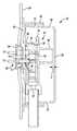
- FIG. 2is a fragmentary section view of the compressor of FIG. 1 ;
- FIG. 3is an additional fragmentary section view of the compressor of FIG. 1 ;
- FIG. 4is a fragmentary section view of an alternate compressor according to the present disclosure.
- FIG. 5is a fragmentary section view of an alternate compressor according to the present disclosure.
- a compressor 10is shown as a hermetic scroll refrigerant-compressor of the low-side type, i.e., where the motor and compressor are cooled by suction gas in the hermetic shell, as illustrated in the vertical section shown in FIG. 1 .
- compressor 10may include a hermetic shell assembly 12 , a main bearing housing assembly 14 , a motor assembly 16 , a compression mechanism 18 , a seal assembly 20 , a refrigerant discharge fitting 22 , a discharge valve assembly 24 , and a terminal assembly 26 .
- Shell assembly 12may house main bearing housing assembly 14 , motor assembly 16 , and compression mechanism 18 .
- Shell assembly 12may generally form a compressor housing and may include a cylindrical shell 28 , an end cap 30 at the upper end thereof, a transversely extending partition 32 , and a base 34 at a lower end thereof. End cap 30 and partition 32 may generally define a discharge chamber 36 . Discharge chamber 36 may generally form a discharge muffler for compressor 10 . Refrigerant discharge fitting 22 may be attached to shell assembly 12 at opening 38 in end cap 30 . Discharge valve assembly 24 may be located within discharge fitting 22 and may generally prevent a reverse flow condition. Partition 32 may include a discharge passage 40 therethrough providing communication between compression mechanism 18 and discharge chamber 36 .
- Main bearing housing assembly 14may be affixed to shell 28 at a plurality of points in any desirable manner, such as staking.
- Main bearing housing assembly 14may include a main bearing housing 42 .
- Motor assembly 16may generally include a motor stator 44 , a rotor 46 , and a drive shaft 48 .
- Motor stator 44may be press fit into shell 28 .
- Drive shaft 48may be rotatably driven by rotor 46 and may extend through main bearing housing 42 .
- Compression mechanism 18may generally include an orbiting scroll 50 and a non-orbiting scroll 52 .
- Orbiting scroll 50may be supported on main bearing housing 42 and may be driven by drive shaft 48 .
- An Oldham coupling 54may be engaged with the orbiting and non-orbiting scrolls 50 , 52 to prevent relative rotation therebetween.
- Non-orbiting scroll 52may be rotationally secured to main bearing housing 42 and may be axially displaceable relative to main bearing housing 42 and orbiting scroll 50 .
- Seal assembly 20may include a floating seal engaged with partition 32 and non-orbiting scroll 52 .
- Seal assembly 20may be axially displaceable relative to shell assembly 12 and non-orbiting scroll 52 and may provide for axial displacement of non-orbiting scroll 52 while maintaining a sealed engagement with partition 32 to isolate discharge and suction pressure regions of compressor 10 from one another.
- Terminal assembly 26may be coupled to shell assembly 12 to provide electrical communication to compressor 10 from an external source.
- terminal assembly 26may include a mounting bracket 56 , a cover 58 , a gasket 60 , a terminal block 62 , and a plug 64 .
- Mounting bracket 56may be fixed to shell assembly 12 , surrounding an opening 66 housing terminal block 62 .
- Cover 58may be secured to bracket 56 in a variety of ways including a snap-fit engagement and may include a rear wall 68 having sidewalls 70 extending therefrom toward shell assembly 12 .
- Gasket 60may be formed from a compressible material such as a foam or an elastomer and may be located between cover 58 and shell assembly 12 . More specifically, gasket 60 may be formed from neoprene. The engagement between mounting bracket 56 and cover 58 may compress gasket 60 between sidewalls 70 and shell assembly 12 , forming a first sealing region.
- Terminal block 62may include pins 72 having ceramic insulators 74 , fused glass insulators 75 , and rubber boots 77 disposed thereon.
- Plug 64may be engaged with pins 72 . More specifically, plug 64 may include first and second portions 76 , 78 . First portion 76 may be housed within second portion 78 and may define receptacles 80 receiving pins 72 and providing electrical communication between pins 72 and a wire 82 .
- Second portion 78may include a first recess 84 on a first side and a protrusion 86 a second side.
- the first sidemay face the terminal block 62 and the second side may face the cover 58 .
- First recess 84may define a wall 88 housing first portion 76 .
- the engagement between pins 72 and receptacles 80may maintain an engagement between first portion 76 and gasket 60 , causing gasket 60 to be compressed against shell assembly 12 and forming a second sealing region.
- the engagement between pins 72 and receptacles 80may additionally cause rubber boots 77 to abut first portion 76 forming a third sealing region.
- Protrusion 86may extend outward from shell assembly 12 generally toward rear wall 68 of cover 58 .
- protrusion 86When pins 72 are fully installed within receptacles 80 , protrusion 86 may be spaced from rear wall 68 a distance (D).
- the spacing (D) between protrusion 86 and rear wall 68may limit a disengagement between pins 72 and receptacles 80 . More specifically, the distance (D) may maintain at least a fifty percent engagement between pins 72 and receptacles 80 .
- Plug 64may compress gasket 60 a distance greater than the distance (D) when fully engaged with pins 72 .
- protrusion 186may define a cavity 190 housing a resilient member 192 , such as an elastomeric member.
- the member 192may abut protrusion 186 and wall 168 of cover 158 to maintain engagement of plug 164 while limiting vibration transmission between cover 158 and plug 164 .
- protrusion 286may define a cavity 290 housing a piston member 292 and a biasing member 294 .
- the member 292may be forced into contact with wall 268 by biasing member 294 .
- the engagement of biasing member 294 with plug 264 and piston member 292may maintain engagement of plug 264 while limiting vibration transmission between cover 258 and plug 264 .
Landscapes
- Engineering & Computer Science (AREA)
- Mechanical Engineering (AREA)
- General Engineering & Computer Science (AREA)
- Compressor (AREA)
- Motor Or Generator Frames (AREA)
Abstract
Description
Claims (21)
Priority Applications (1)
| Application Number | Priority Date | Filing Date | Title |
|---|---|---|---|
| US12/684,386US9331420B2 (en) | 2009-01-09 | 2010-01-08 | Compressor having terminal plug assembly |
Applications Claiming Priority (2)
| Application Number | Priority Date | Filing Date | Title |
|---|---|---|---|
| US14360709P | 2009-01-09 | 2009-01-09 | |
| US12/684,386US9331420B2 (en) | 2009-01-09 | 2010-01-08 | Compressor having terminal plug assembly |
Publications (2)
| Publication Number | Publication Date |
|---|---|
| US20100196175A1 US20100196175A1 (en) | 2010-08-05 |
| US9331420B2true US9331420B2 (en) | 2016-05-03 |
Family
ID=42317155
Family Applications (1)
| Application Number | Title | Priority Date | Filing Date |
|---|---|---|---|
| US12/684,386Active2033-03-24US9331420B2 (en) | 2009-01-09 | 2010-01-08 | Compressor having terminal plug assembly |
Country Status (5)
| Country | Link |
|---|---|
| US (1) | US9331420B2 (en) |
| EP (1) | EP2307731B1 (en) |
| CN (1) | CN102272455B (en) |
| MX (1) | MX2011007183A (en) |
| WO (1) | WO2010080984A2 (en) |
Cited By (3)
| Publication number | Priority date | Publication date | Assignee | Title |
|---|---|---|---|---|
| US20190267752A1 (en)* | 2016-11-22 | 2019-08-29 | Ebara Corporation | Submersible motor and waterproof connector |
| US11183902B2 (en)* | 2018-04-26 | 2021-11-23 | Hanon Systems | Device for driving a compressor and method for assembling of the device |
| US11480184B2 (en)* | 2017-08-21 | 2022-10-25 | Daikin Industries, Ltd. | Hermetic compressor |
Families Citing this family (16)
| Publication number | Priority date | Publication date | Assignee | Title |
|---|---|---|---|---|
| US8721371B2 (en) | 2011-05-27 | 2014-05-13 | Emerson Climate Technologies, Inc. | Conduit adaptor |
| FR2977407B1 (en)* | 2011-06-30 | 2013-07-05 | Valeo Japan Co Ltd | DEVICE FOR ELECTRICALLY CONNECTING AN ELECTRICAL COMPRESSOR |
| US8801400B2 (en)* | 2011-07-08 | 2014-08-12 | Danfoss Scroll Technologies Llc | Secure connection terminal for hermetic compressor |
| CN102352830B (en)* | 2011-10-28 | 2014-06-18 | 黄石东贝电器股份有限公司 | Sealed compressor shell |
| CN103174623A (en)* | 2011-12-20 | 2013-06-26 | 卢海南 | Water-boiling type refrigeration compressor |
| JP5522184B2 (en)* | 2012-02-02 | 2014-06-18 | 株式会社豊田自動織機 | Electric compressor and its airtightness inspection method |
| US9480177B2 (en)* | 2012-07-27 | 2016-10-25 | Emerson Climate Technologies, Inc. | Compressor protection module |
| US9634538B2 (en)* | 2013-07-31 | 2017-04-25 | Trane International Inc. | Terminal assembly for refrigeration compressor |
| JP2015117690A (en)* | 2013-11-14 | 2015-06-25 | 三星電子株式会社Samsung Electronics Co.,Ltd. | Protective cover and compressor using this protective cover |
| US9851131B2 (en)* | 2013-11-14 | 2017-12-26 | Samsung Electronics Co., Ltd. | Compressor and air conditioner having the same |
| CN104847620B (en)* | 2015-04-28 | 2017-10-10 | 胡金花 | Automobile electric fuel pump |
| JP6881378B2 (en)* | 2018-03-30 | 2021-06-02 | 株式会社豊田自動織機 | Electric compressor |
| WO2019216834A1 (en)* | 2018-05-07 | 2019-11-14 | Siam Compressor Industry Co., Ltd. | Power supply wire connecting structure for hermetic compressor |
| FR3147666A1 (en)* | 2023-04-06 | 2024-10-11 | Psa Automobiles Sa | compressor for a motor vehicle air conditioning system |
| CN119009841A (en)* | 2023-05-16 | 2024-11-22 | 南昌海立电器有限公司 | Junction box and compressor |
| JP2025087055A (en)* | 2023-11-29 | 2025-06-10 | パナソニックIpマネジメント株式会社 | Sealed structure, compressor equipped with sealed structure, refrigeration cycle device equipped with compressor, and terminal cover |
Citations (19)
| Publication number | Priority date | Publication date | Assignee | Title |
|---|---|---|---|---|
| US1635507A (en)* | 1926-11-04 | 1927-07-12 | Edward T Seasock | Attachment for electric extension plugs |
| US3160460A (en)* | 1962-01-17 | 1964-12-08 | Fusite Corp | Terminal assembly having conductor pins and connector block |
| US4512724A (en) | 1983-03-17 | 1985-04-23 | Metaframe, Inc. | Electric pump for use in filtering system of a tropical fish tank or the like |
| US4699592A (en)* | 1985-06-04 | 1987-10-13 | Telcor, Inc. | Rotatable connector |
| US4998035A (en)* | 1990-07-26 | 1991-03-05 | American Standard Inc. | Method for attaching a motor lead restraint device to a compressor pump |
| US5139431A (en)* | 1990-07-09 | 1992-08-18 | Yazaki Corporation | Waterproofing device for screw-tightened connectors |
| US5199898A (en) | 1991-09-23 | 1993-04-06 | Tecumseh Products Company | External terminal shield |
| US5249899A (en)* | 1992-10-28 | 1993-10-05 | Wilson Robert L | Head bolt and driver therefore |
| JPH0617781A (en) | 1991-06-21 | 1994-01-25 | Hitachi Ltd | Horizontal scroll compressor |
| US5801465A (en)* | 1995-07-03 | 1998-09-01 | Ebara Corporation | Underwater motor with water-proof connector |
| US6155805A (en) | 1997-11-13 | 2000-12-05 | Tecumseh Products Company | Hermetic compressor having acoustic insulator |
| US20020131869A1 (en) | 2001-03-14 | 2002-09-19 | Matsushita Electric Industrial Co., Ltd. | Method for connecting compressor with built-in electric motor and external wiring, connection device used therefor, and compressor with built-in electric motor using the same |
| US20030143892A1 (en) | 2000-07-27 | 2003-07-31 | Delphi Technologies, Inc. | Electrical connector system |
| US20040118146A1 (en) | 2002-12-10 | 2004-06-24 | Haller David K. | Horizontal compressor end cap |
| US20050054234A1 (en) | 2001-07-30 | 2005-03-10 | Daniel Joao Carlos Dobner | Electric connector for the motor of a hermetic compressor and its manufacturing process |
| CN1611781A (en) | 2003-10-30 | 2005-05-04 | 乐金电子(天津)电器有限公司 | Rotary compressor |
| WO2006041147A1 (en) | 2004-10-14 | 2006-04-20 | Matsushita Electric Industrial Co., Ltd. | Compressor, refrigerating device, and refrigerator |
| CN101184919A (en) | 2005-05-30 | 2008-05-21 | 三电有限公司 | electric compressor |
| JP2008169754A (en)* | 2007-01-11 | 2008-07-24 | Daikin Ind Ltd | Compressor |
- 2010
- 2010-01-08CNCN201080004242.8Apatent/CN102272455B/enactiveActive
- 2010-01-08EPEP20100729558patent/EP2307731B1/enactiveActive
- 2010-01-08MXMX2011007183Apatent/MX2011007183A/enactiveIP Right Grant
- 2010-01-08USUS12/684,386patent/US9331420B2/enactiveActive
- 2010-01-08WOPCT/US2010/020478patent/WO2010080984A2/enactiveApplication Filing
Patent Citations (22)
| Publication number | Priority date | Publication date | Assignee | Title |
|---|---|---|---|---|
| US1635507A (en)* | 1926-11-04 | 1927-07-12 | Edward T Seasock | Attachment for electric extension plugs |
| US3160460A (en)* | 1962-01-17 | 1964-12-08 | Fusite Corp | Terminal assembly having conductor pins and connector block |
| US4512724A (en) | 1983-03-17 | 1985-04-23 | Metaframe, Inc. | Electric pump for use in filtering system of a tropical fish tank or the like |
| US4699592A (en)* | 1985-06-04 | 1987-10-13 | Telcor, Inc. | Rotatable connector |
| US5139431A (en)* | 1990-07-09 | 1992-08-18 | Yazaki Corporation | Waterproofing device for screw-tightened connectors |
| US4998035A (en)* | 1990-07-26 | 1991-03-05 | American Standard Inc. | Method for attaching a motor lead restraint device to a compressor pump |
| JPH0617781A (en) | 1991-06-21 | 1994-01-25 | Hitachi Ltd | Horizontal scroll compressor |
| US5199898A (en) | 1991-09-23 | 1993-04-06 | Tecumseh Products Company | External terminal shield |
| US5336105A (en)* | 1991-09-23 | 1994-08-09 | Tecumseh Products Company | External terminal shield |
| US5249899A (en)* | 1992-10-28 | 1993-10-05 | Wilson Robert L | Head bolt and driver therefore |
| US5801465A (en)* | 1995-07-03 | 1998-09-01 | Ebara Corporation | Underwater motor with water-proof connector |
| US6155805A (en) | 1997-11-13 | 2000-12-05 | Tecumseh Products Company | Hermetic compressor having acoustic insulator |
| US20030143892A1 (en) | 2000-07-27 | 2003-07-31 | Delphi Technologies, Inc. | Electrical connector system |
| US20020131869A1 (en) | 2001-03-14 | 2002-09-19 | Matsushita Electric Industrial Co., Ltd. | Method for connecting compressor with built-in electric motor and external wiring, connection device used therefor, and compressor with built-in electric motor using the same |
| US6779989B2 (en)* | 2001-03-14 | 2004-08-24 | Matsushita Electric Industrial Co., Ltd. | Method for connecting compressor with built-in electric motor and external wiring, connection device used therefor, and compressor with built-in electric motor using the same |
| US20050054234A1 (en) | 2001-07-30 | 2005-03-10 | Daniel Joao Carlos Dobner | Electric connector for the motor of a hermetic compressor and its manufacturing process |
| US20040118146A1 (en) | 2002-12-10 | 2004-06-24 | Haller David K. | Horizontal compressor end cap |
| US20060147314A1 (en)* | 2002-12-10 | 2006-07-06 | Haller David K | Horizontal compressor end cap |
| CN1611781A (en) | 2003-10-30 | 2005-05-04 | 乐金电子(天津)电器有限公司 | Rotary compressor |
| WO2006041147A1 (en) | 2004-10-14 | 2006-04-20 | Matsushita Electric Industrial Co., Ltd. | Compressor, refrigerating device, and refrigerator |
| CN101184919A (en) | 2005-05-30 | 2008-05-21 | 三电有限公司 | electric compressor |
| JP2008169754A (en)* | 2007-01-11 | 2008-07-24 | Daikin Ind Ltd | Compressor |
Non-Patent Citations (6)
| Title |
|---|
| Chinese Office Action mailed Aug. 27, 2013 regarding Chinese Application No. 201080004242.8. Translation provided by Unitalen Attorneys at Law. |
| Extended European Search Report regarding Application No. 10729558.6-2315/2307731, dated Feb. 28, 2012. |
| International Search Report regarding International Application No. PCT/US2010/020478, dated Aug. 23, 2010. |
| Machine Translation of Japanese Patent JP 2008169754.* |
| Second Chinese Office Action mailed Apr. 28, 2014 regarding Chinese Application No. 2010800042428 Translation provided by Unitalen Attorneys At Law. |
| Written Opinion of the International Searching Authority regarding International Application No. PCT/US2010/020478, dated Aug. 23, 2010. |
Cited By (4)
| Publication number | Priority date | Publication date | Assignee | Title |
|---|---|---|---|---|
| US20190267752A1 (en)* | 2016-11-22 | 2019-08-29 | Ebara Corporation | Submersible motor and waterproof connector |
| US10693258B2 (en)* | 2016-11-22 | 2020-06-23 | Ebara Corporation | Submersible motor and waterproof connector |
| US11480184B2 (en)* | 2017-08-21 | 2022-10-25 | Daikin Industries, Ltd. | Hermetic compressor |
| US11183902B2 (en)* | 2018-04-26 | 2021-11-23 | Hanon Systems | Device for driving a compressor and method for assembling of the device |
Also Published As
| Publication number | Publication date |
|---|---|
| CN102272455B (en) | 2015-02-25 |
| US20100196175A1 (en) | 2010-08-05 |
| WO2010080984A2 (en) | 2010-07-15 |
| MX2011007183A (en) | 2011-08-03 |
| CN102272455A (en) | 2011-12-07 |
| EP2307731B1 (en) | 2014-07-09 |
| EP2307731A4 (en) | 2012-03-28 |
| EP2307731A2 (en) | 2011-04-13 |
| WO2010080984A3 (en) | 2010-10-21 |
Similar Documents
| Publication | Publication Date | Title |
|---|---|---|
| US9331420B2 (en) | Compressor having terminal plug assembly | |
| EP0479421B1 (en) | Scroll machine with floating seal | |
| US9145891B2 (en) | Scroll compressor | |
| US5156539A (en) | Scroll machine with floating seal | |
| US8043078B2 (en) | Compressor sealing arrangement | |
| CN101356366A (en) | Electric compressor | |
| CN108474475B (en) | Sealing structure of airtight container, and vehicle refrigerant compressor having the same | |
| CN101346547B (en) | Electric compressor | |
| WO2006129448A1 (en) | Electric compressor | |
| CN109844318B (en) | Scroll compressor having a plurality of scroll members | |
| JP5691352B2 (en) | Scroll compressor | |
| WO2022172712A1 (en) | Terminal unit and compressor | |
| EP1867874B1 (en) | Electric motor-driven compressor | |
| US20040115063A1 (en) | Scroll compressor | |
| CN204267285U (en) | Scroll compressor | |
| KR100348609B1 (en) | Suction and discharge pressure separation structure for scroll compressor | |
| US20100254833A1 (en) | Terminal device for electric compressor | |
| KR100774057B1 (en) | Discharge valve assembly of linear compressor | |
| KR200229011Y1 (en) | Structure for sealing active gas in scroll compressor | |
| WO2023204301A1 (en) | Compressor | |
| KR100608868B1 (en) | Assembly structure of scroll compressor | |
| JP2014029119A (en) | Screw compressor | |
| TWI399485B (en) | Scroll compressor | |
| KR200162038Y1 (en) | Terminal of Hermetic Compressor | |
| JPH11287191A (en) | Horizontal scroll compressor |
Legal Events
| Date | Code | Title | Description |
|---|---|---|---|
| AS | Assignment | Owner name:EMERSON CLIMATE TECHNOLOGIES, INC., OHIO Free format text:ASSIGNMENT OF ASSIGNORS INTEREST;ASSIGNORS:BEDELL, RICK T.;HEMMELGARN, GREGG M.;HEIDECKER, MATTHEW J.;SIGNING DATES FROM 20100216 TO 20100414;REEL/FRAME:024239/0493 | |
| STCF | Information on status: patent grant | Free format text:PATENTED CASE | |
| MAFP | Maintenance fee payment | Free format text:PAYMENT OF MAINTENANCE FEE, 4TH YEAR, LARGE ENTITY (ORIGINAL EVENT CODE: M1551); ENTITY STATUS OF PATENT OWNER: LARGE ENTITY Year of fee payment:4 | |
| AS | Assignment | Owner name:COPELAND LP, OHIO Free format text:ENTITY CONVERSION;ASSIGNOR:EMERSON CLIMATE TECHNOLOGIES, INC.;REEL/FRAME:064058/0724 Effective date:20230503 | |
| AS | Assignment | Owner name:WELLS FARGO BANK, NATIONAL ASSOCIATION, AS COLLATERAL AGENT, CALIFORNIA Free format text:SECURITY INTEREST;ASSIGNOR:COPELAND LP;REEL/FRAME:064280/0695 Effective date:20230531 Owner name:U.S. BANK TRUST COMPANY, NATIONAL ASSOCIATION, AS NOTES COLLATERAL AGENT, MINNESOTA Free format text:SECURITY INTEREST;ASSIGNOR:COPELAND LP;REEL/FRAME:064279/0327 Effective date:20230531 Owner name:ROYAL BANK OF CANADA, AS COLLATERAL AGENT, CANADA Free format text:SECURITY INTEREST;ASSIGNOR:COPELAND LP;REEL/FRAME:064278/0598 Effective date:20230531 | |
| MAFP | Maintenance fee payment | Free format text:PAYMENT OF MAINTENANCE FEE, 8TH YEAR, LARGE ENTITY (ORIGINAL EVENT CODE: M1552); ENTITY STATUS OF PATENT OWNER: LARGE ENTITY Year of fee payment:8 | |
| AS | Assignment | Owner name:U.S. BANK TRUST COMPANY, NATIONAL ASSOCIATION, AS NOTES COLLATERAL AGENT, MINNESOTA Free format text:SECURITY INTEREST;ASSIGNOR:COPELAND LP;REEL/FRAME:068241/0264 Effective date:20240708 |