US9330105B1 - Systems, methods, and computer readable media for lazy compression of data incoming to a data storage entity - Google Patents
Systems, methods, and computer readable media for lazy compression of data incoming to a data storage entityDownload PDFInfo
- Publication number
- US9330105B1 US9330105B1US12/822,173US82217310AUS9330105B1US 9330105 B1US9330105 B1US 9330105B1US 82217310 AUS82217310 AUS 82217310AUS 9330105 B1US9330105 B1US 9330105B1
- Authority
- US
- United States
- Prior art keywords
- data
- logical unit
- compressed
- chunk
- data storage
- Prior art date
- Legal status (The legal status is an assumption and is not a legal conclusion. Google has not performed a legal analysis and makes no representation as to the accuracy of the status listed.)
- Active, expires
Links
Images


Classifications
- G—PHYSICS
- G06—COMPUTING OR CALCULATING; COUNTING
- G06F—ELECTRIC DIGITAL DATA PROCESSING
- G06F16/00—Information retrieval; Database structures therefor; File system structures therefor
- G06F16/10—File systems; File servers
- G06F16/17—Details of further file system functions
- G06F16/174—Redundancy elimination performed by the file system
- G06F16/1744—Redundancy elimination performed by the file system using compression, e.g. sparse files
- H—ELECTRICITY
- H03—ELECTRONIC CIRCUITRY
- H03M—CODING; DECODING; CODE CONVERSION IN GENERAL
- H03M7/00—Conversion of a code where information is represented by a given sequence or number of digits to a code where the same, similar or subset of information is represented by a different sequence or number of digits
- H03M7/30—Compression; Expansion; Suppression of unnecessary data, e.g. redundancy reduction
- G06F17/30153—
- H—ELECTRICITY
- H03—ELECTRONIC CIRCUITRY
- H03M—CODING; DECODING; CODE CONVERSION IN GENERAL
- H03M7/00—Conversion of a code where information is represented by a given sequence or number of digits to a code where the same, similar or subset of information is represented by a different sequence or number of digits
- H03M7/30—Compression; Expansion; Suppression of unnecessary data, e.g. redundancy reduction
- H03M7/60—General implementation details not specific to a particular type of compression
- H03M7/6047—Power optimization with respect to the encoder, decoder, storage or transmission
- G—PHYSICS
- G06—COMPUTING OR CALCULATING; COUNTING
- G06F—ELECTRIC DIGITAL DATA PROCESSING
- G06F12/00—Accessing, addressing or allocating within memory systems or architectures
- G06F12/02—Addressing or allocation; Relocation
- G06F12/0223—User address space allocation, e.g. contiguous or non contiguous base addressing
- G06F12/023—Free address space management
- G06F12/0238—Memory management in non-volatile memory, e.g. resistive RAM or ferroelectric memory
- G06F12/0246—Memory management in non-volatile memory, e.g. resistive RAM or ferroelectric memory in block erasable memory, e.g. flash memory
Definitions
- the subject matter described hereinrelates to methods and systems for managing data in data storage devices. More particularly, the subject matter described herein relates to systems, methods, and computer readable media for lazy compression of data incoming to a data storage entity.
- the datamay be compressed at the time of writing, e.g., compressed data, rather than uncompressed data, is written to the data storage device.
- Some algorithmsperform compression by replacing often-repeated sequences of text or data with substitute placeholder that is smaller in size than the sequence that it replaces.
- the larger the sequences that are replacedthe more efficient the algorithm becomes, allowing the compressed file to be smaller and smaller relative to the size of the uncompressed file.
- Such compression algorithmswill first search the entirety of the data to be compressed, called the compression domain, to find the largest sequences that are repeated within the compression domain.
- the larger the compression domainthe more opportunities there are for the compression algorithm to find larger repeating sequences. For this reason, compression algorithms tend to be more efficient as the compression domain gets larger.
- a compression domainmay be very large if the data within its boundaries—i.e., the contents of that compression domain—do not change very often.
- One approach to selecting the boundary of a compression domainis to attempt to encompass data that will be likely to change together or not change at all. That is, if one portion of the data within the compression domain changes, other portions of the data within the compression domain are also likely to change, resulting in a decompress-modify-modify-modify-recompress strategy.
- Thisincreases efficiency because the decompress and recompress operations are typically more resource-intensive than the modify operations. In other words, if the system has to go to the trouble of decompressing and recompressing, the overhead caused by multiple modifications is relatively small in comparison.
- file-based compressionin which the file construct is the boundary of the compression domain: one file is one compression domain, another file is another compression domain, and so on.
- file-based compressionThere are disadvantages to file-based compression, however.
- Storage devicesmay not operate at the file level, and thus may not even be aware of the file construct.
- a hard disk drivemay respond to requests for logical blocks of available storage space, without knowing to which file, if any, those logical blocks belong.
- file-based compressioncannot be implemented by a low level entity, such as the storage device, but must be controlled by a higher-level entity, i.e., one that is aware of the file structure and the mapping of file to logical or physical addresses within the storage device.
- the file itselfis compressed, but the meta-data that describes the file or its location, such as the directory entry for the file, is not compressed.
- the file contentsmust be compressed before being sent to the data storage device: the data storage system receives commands to write the already compressed data to the data storage device. Furthermore, the file system must maintain information with each file to indicate whether the file data that is stored on the data storage is device is compressed or uncompressed data.
- the compression domainis not based on a storage block's membership in a file, but on the storage block's membership with a unit of reservation or a unit of allocation.
- This approachhas the advantage that compression can be performed at a low level, e.g., by the allocation or reservation entity or even by the storage device itself, without having to know the higher-level file or directory structures.
- the file systemoperates as if every file is uncompressed, and will send and receive uncompressed file data, which is silently compressed before write to the data storage device and uncompressed upon read from the data storage device.
- any write into the logical unitcan potentially require (and probably will require) the decompress-modify-recompress operation to be performed.
- the decompress and recompress stepsare resource-intensive (and therefore also time-intensive).
- the compression operationis multiple times more resource intensive than the decompression operation. For systems that perform multiple decompress-modify-recompress operations, this can cause a severe bottleneck in performance when reading from and writing to a compressed logical unit.
- the subject matter described hereinincludes a method for lazy compression of data incoming to a data storage entity.
- the methodincludes defining at least a portion of the data storage area within the data storage entity as a compressed logical unit for storing at least some data in compressed form.
- a command to write data to the compressed logical unitis received, and, in response to receiving the command to write data to the compressed logical unit, the data is written to the compressed logical unit in uncompressed form.
- the methodalso includes monitoring for a trigger condition, and, upon detection of a trigger condition, compressing at least a portion of the uncompressed data within the compressed logical unit.
- the subject matter described hereinincludes a method for lazy decompression of a compressed portion of a data storage entity.
- the compressed logical unitis designated as being subject to lazy decompression.
- a command to read data from or write data to a compressed target portion of the compressed logical unitis received.
- the compressed target portionis decompressed, and the read or write command is performed on the uncompressed target portion. Compressed portions of the compressed logical unit that are not the target of any read or write command are not decompressed.
- the subject matter described hereinincludes a system for lazy compression of data incoming to a data storage entity.
- the systemincludes multiple data storage devices having data storage space for storing data, the collective data storage space being divided into a plurality of slices for allocation to at least one compressed logical unit for storing at least some data in compressed form.
- the systemincludes a first module for receiving a command to write data to the compressed logical unit, and, in response to receiving the command to write data to the compressed logical unit, writing the data to the compressed logical unit in uncompressed form.
- the systemincludes a second module for monitoring for a trigger condition, and, upon detection of a trigger condition, compressing at least a portion of the uncompressed data within the compressed logical unit.
- the subject matter described herein for lazy compression of data incoming to a data storage entitymay be implemented in hardware, software, firmware, or any combination thereof.
- the terms “function” or “module” as used hereinrefer to hardware, software, and/or firmware for implementing the feature being described.
- the subject matter described hereinmay be implemented using a computer readable medium having stored thereon computer executable instructions that when executed by the processor of a computer control the computer to perform steps.
- Exemplary computer readable media suitable for implementing the subject matter described hereininclude non-transitory computer-readable media, such as disk memory devices, chip memory devices, programmable logic devices, and application specific integrated circuits.
- a computer readable medium that implements the subject matter described hereinmay be located on a single device or computing platform or may be distributed across multiple devices or computing platforms.
- FIG. 1Ais a block diagram illustrating a compression operations lifecycle according to an embodiment of the subject matter described herein;
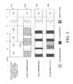
- FIG. 1Bis a bar graph illustrating the principle of operation of lazy compression according to an embodiment of the subject matter described herein;
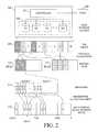
- FIG. 2is block diagram illustrating an exemplary system for lazy compression of data incoming to a data storage entity according to an embodiment of the subject matter described herein;
- FIG. 3illustrates an exemplary logical unit that has been divided into compression domains, called chunks, according to an embodiment of the subject matter described herein;
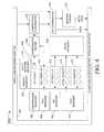
- FIG. 4is a block diagram illustrating a controller for implementing an exemplary system for lazy compression of data incoming to a data storage entity according to another embodiment of the subject matter described herein;
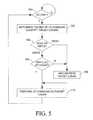
- FIG. 5is a flow chart illustrating an exemplary process for lazy compression of data incoming to a data storage entity according to an embodiment of the subject matter described herein;
- FIG. 6is a flow chart illustrating another exemplary process for lazy compression of data incoming to a data storage entity according to an embodiment of the subject matter described herein;
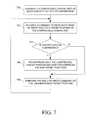
- FIG. 7is a flow chart illustrating an exemplary process for lazy decompression of a compressed portion of a data storage entity according to an embodiment of the subject matter described herein.
- systems, methods, and computer readable mediaare provided for lazy compression of data incoming to a data storage entity.
- datais not written to the logical unit in compressed form, but is instead written to the logical unit in uncompressed form, and compressed when and if necessary.
- block-based compression domainsare used.
- a single logical unitmay include multiple compression domains.
- FIG. 1Ais a block diagram illustrating a compression operations lifecycle according to an embodiment of the subject matter described herein.
- a volume of data storagesuch as a logical unit, may begin in an uncompressed state 100 , meaning that data contained within the volume, if any, is not compressed.
- initial compression 102Upon initiation of an initial compression 102 , compression for the volume is turned on, meaning that all incoming data is at least potentially subject to compression. If the volume already contains uncompressed data, the data on that volume is compressed.
- the result of initial compression 102is the creation of a volume in a compressed state 104 . This volume will be subject to recompression 106 in response to the detection of certain triggers, such as the detection of a threshold condition.
- the volume in compressed state 104may be recompressed multiple times.
- a decompression 108Upon initiation of a decompression 108 , such as if the volume type is changed to uncompressed type or if the volume is otherwise converted to an uncompressed volume, compression is turned off for incoming data, and any data currently existing within the volume is decompressed. As a result of decompression 108 , the volume is decompressed 110 , e.g., the volume returns to the uncompressed state.
- recompression step 106may be deferred, perhaps indefinitely. An example of this behavior is illustrated in FIG. 1B .
- FIG. 1Bis a bar graph illustrating the principle of operation of lazy compression according to an embodiment of the subject matter described herein.
- the Y axisindicates the capacity of an example logical unit and how the utilization of that capacity changes over time, which is shown on the X axis.
- the state of the logical unitis shown at various times labeled T 1 through T 13 .
- T 1the logical unit contains only uncompressed data, and is at approximately 75% utilization.
- the logical unitis changed from an “uncompressed” type, i.e., one that stores only uncompressed data, to a “compressed” type, i.e., one that stores compressed data but also may store uncompressed data according to the lazy compression approach described herein.
- an “uncompressed” typei.e., one that stores only uncompressed data
- a “compressed” typei.e., one that stores compressed data but also may store uncompressed data according to the lazy compression approach described herein.
- all of the data in the logical unithas been compressed, to approximately 25% utilization.
- Time T 5illustrates one type of trigger condition, a change in the utilization. In the example shown in FIG. 1 , at time T 5 the utilization of the logical unit changes by more than 50% from the previous utilization.
- the amount of data stored in the logical unit at time T 5is more than 150% of the amount of the data that was stored in the logical unit at time T 4 .
- the logical unitis compressed, and at time T 6 , the logical unit again contains only compressed data, and is approximately 60% utilized.
- the systemdetermines whether the data to be modified exists on the logical unit as compressed or uncompressed data. If the data to be modified exists on the logical unit as compressed data, the system may uncompress the data, modify the uncompressed data, and write the modified data back to the logical unit. Instead of writing the data back to the logical unit in compressed form, the system writes the data back to the logical unit in uncompressed form.
- the new datamay be written to the logical unit, either overwriting compressed data currently stored within the chunk with new, uncompressed data, or alternatively, writing the uncompressed data to one or more new 8 KB mapping units, mapping the new 8 KB mapping units into the MLU logical address space, and deallocating the 8 KB mapping units that were formerly mapped to that same MLU logical address space so that the mapping units may be used to store something else. This avoids the need to perform a decompression and thus saves time and resources.
- Time T 11 and T 12illustrate how utilization may be reduced.
- a portion of the compressed datamay be deleted from the logical unit.
- the location of the data to be deletedmust be located within the compressed data area, and that portion of the compressed data must be decompressed, as shown at time T 11 , before the data to be discarded can be deleted, as shown by the reduced size of the uncompressed data at time T 12 .
- the undeleted portion of the uncompressed datais not recompressed, and at time T 13 , additional data is written to the logical unit.
- FIG. 2is block diagram illustrating an exemplary system for lazy compression of data incoming to a data storage entity according to an embodiment of the subject matter described herein.
- Data storage system 200includes a controller 202 for communicating with one or more hosts 204 to read and write data to one or more data storage devices 206 , whose collective data storage capacity is represented as data storage area 208 .
- data storage system 200has N number of data storage devices, labeled D 1 through DN.
- Data storage devices 206may include hard disk drives, floppy disk drives, tape drives, FLASH drives, or any other form of persistent storage.
- data storage devices 206may be organized into redundant arrays of inexpensive disks (RAID) groups.
- the total data storage area 208may be divided into slices for allocation to one or more logical units, or LUs.
- data storage area 208is divided into M number of 1 gigabyte (1 GB) slices.
- the pool of data storage devices 206are first divided into RAID groups, which are themselves divided into several logical units each. 1 GB slices are provisioned from those logical units.
- data storage system 200supports sparsely allocated logical units, also called thinly allocated logical units (TLUs), in which slices are allocated to the logical unit as needed, in contrast to fully allocated logical units, in which all of the slices that the logical unit will ever need based on its projected maximum size are allocated to the logical unit at the time of its creation.
- TLUsthinly allocated logical units
- data storage system 200supports mapped logical units, or MLUs, in which the slices that are allocated to the TLU are not necessarily contiguous within the collective data storage area.
- mapped MLU 1 210has been allocated two slices from data storage area 208 —namely, slice 4 and slice 1 .
- MLU 2 212has been allocated three slices from data storage area 208 —namely, slice 2 , slice 9 , and slice 6 .
- each slicemay be further subdivided into portions that are allocated and mapped to the MLU as needed. These portions of a slice are herein referred to as “mapping allocation units”. In the embodiment illustrated in FIG. 2 , mapping allocation units are 8 KB in size, but other sizes could also be used. In this scenario, slices are said to be provisioned to an MLU, and portions of the slice are said to be allocated to specific ranges of logical block addresses within the MLU.
- the data storage area represented by slices 4 and 1are represented as container 214 , which is a data structure that allows the MLU to be presented as a data storage area having a logical block address space larger than the physical space that is actually present.
- Container 214maps the 8 KB mapping allocation units into the logical block address space of MLU 1 210 , which is represented as element 216 in FIG. 2 .
- the 8K mapping allocation unitsneed not be mapped into contiguous logical block address spaces, and that the 8K mapping allocation units may be allocated from any 1 GB slice.
- 8 KB mapping allocation units B, C, and Doccupy contiguous portions of the logical block address space of MLU 1 210 , but do not occupy contiguous portions of slice 4 or slice 1 .
- mapping allocation units B and Care allocated from slice 4 while mapping allocation unit D is allocated from slice 1 .
- logical block address space 216is divided into compression domains, called “chunks”. As stated above, the size of a chunk should be chosen as a compromise between compression efficiency (which increases with increasing chunk size) and system performance (which decreases with increasing chunk size.) In one embodiment, illustrated in FIG. 3 , a chunk size of 64 KB is chosen.
- FIG. 3illustrates an exemplary logical unit that has been divided into compression domains, called chunks, according to an embodiment of the subject matter described herein.
- the storage space of MLU 1 210is shown as presented to a user, i.e., as logical block address space 216 , which has logical block addresses ranging from LBA 0 through LBA Z.
- Logical block address space 216is divided into multiple 64 KB chunks, labeled C 1 through CL.
- Logical block addresses S, T, U, V, and Yrepresent address boundaries between the 64 KB blocks.
- Each chunk C 1 through CLis treated as an independent compression domain.
- FIG. 3illustrates three snapshots of the contents of a logical unit, such as MLU 1 210 , that implements lazy compression according to an embodiment of the subject matter described herein.
- Snapshot 300shows the contents of MLU 1 210 before compression.
- each of chunks C 1 through C 4contains uncompressed data.
- chunk CLcontains no data.
- Snapshot 302shows the contents of MLU 1 210 after compression, showing that each of chunks C 1 through C 4 has been compressed.
- Snapshot 304shows the contents of MLU 1 210 after data has been written to the second chunk, C 2 .
- a write to a logical block address within C 2triggers data storage system 200 to determine whether that chunk is currently compressed or not.
- chunk C 2has been compressed.
- the data within chunk C 2is then decompressed for reading or writing.
- unused portions of a chunkmay be zero-filled upon decompression. For example, in snapshot 300 , only a portion of chunk C 2 contained data prior to compression, but in snapshot 304 , the formerly unused portion of chunk C 2 has been zero filled.
- the uncompressed datacan be read from chunk C 2 . If the chunk is to be written, the write may proceed, e.g., by writing or modifying data within chunk C 2 . After either a read or a write, the system does not necessarily recompress the data within chunk C 2 . Instead, this recompression will occur only when and if needed, according to the principles of lazy compression described above with regard to FIG. 1 .
- FIG. 4is a block diagram illustrating a controller for implementing an exemplary system for lazy compression of data incoming to a data storage entity according to another embodiment of the subject matter described herein.
- controller 202 from FIG. 2is shown in more detail.
- Controller 202includes an interface 400 for receiving I/O requests from a host and for controlling the storage devices within the system. Because interface 400 is often in a shape that resembles a physical C-shaped clamp, interface 400 is colloquially referred to as “the C-clamp” having an “upper arm” that handles communication to and from the hosts and a “lower arm” that handles communication to and from the hard disk drives or other storage devices.
- controller 202includes a compression manager 402 , which is a collection of interface routines to assist other components in interacting with data that is stored in various data constructs, called “objects”, which are used by controller 202 .
- Controller 202also includes a compression engine (CE) object 404 , which is an object representing the compression engine 406 .
- CE object 404is used to store global data relevant to compression, such as the global pause/resume and compression/decompression/recompression state.
- Compression engine 406provides the background service that is used to compress, decompress, or recompress TLUs and MLUs.
- Controller 202includes a mapped logical unit (MLU) manager 408 for managing MLU objects 410 , a mapping system (MS) manager 412 for managing MS objects 414 , a pool manager 416 for managing pool objects 418 and RAID based logical unit objects (also known as “Flare” logical units, or FLUs) objects 420 .
- An object manager 422 and state machine manager 424are used to track and maintain the various objects (MLU, MS, pool, and FLU objects, for example) used by controller 202 .
- a slice manager 426is responsible for allocation of slices to logical units.
- MLU manager 408handles the control path and provides support for the logic in the I/O path by providing access to control path data.
- a compression coordinator 428processes host I/O requests that are received by the upper arm of C-clamp 400 and passed to compression coordinator 428 , if compression is turned on, or to I/O coordinator 430 , if compression is turned off. To service host I/O requests, compression coordinator 428 , which is a component in the I/O path, will locate the appropriate chunk(s) and coordinate with compression engine 406 to decompress them if necessary.
- I/O coordinator 430waits for compression coordinator 428 to indicate that the uncompressed data is ready before processing the I/O request. I/O coordinator 430 sends write data to the lower arm of C-clamp 400 for eventual storage within data storage devices 206 . I/O coordinator passes data to a mapping system 432 . Mapping system 432 provides meta-data to the lower arm of C-clamp 400 .
- compression coordinator 428takes incoming I/O from both the C-clamp 400 upper arm and from compression engine 406 , establishes the internal data layout, and manages all sub-I/O necessary to complete a given incoming I/O request.
- compression coordinator 428will arrange data in a specialized layout to ensure the availability of a logical block address range for both compressed and uncompressed data for any given chunk.
- compression engine 406is a throttled, pause-able background service that uses a compression library to compress or decompress the data.
- compression engine 406may start a number of work threads for performing the compression, recompression, or decompression operations. When all work threads are active, subsequent compression operations will be queued within the compression engine 406 .
- compression engine 406will interact with compression coordinator 430 to compress or decompress a chunk.
- Compression coordinator 430will complete the request and provide notification of the status, such as: successful, out of space, out of other resources like chunk buffers, or I/O error. If chunk compression fails, compression engine 406 may simply proceed to the next chunk. If chunk decompression fails, compression engine 406 may stop decompression and log an error.
- compression engine 426may monitor compression engine object 406 , which may indicate that a TLU is subject to an initial compression, a recompression, a decompression, etc.
- initial compressionapplies to every chunk in the TLU.
- compression engine 426may request a list of uncompressed extents from compression coordinator 430 .
- both initial compression and recompressionwill proceed in a forward fashion, updating a persistent status marker after a predetermined number of chunks have been processed. If a chunk behind the progress marker is decompressed to service a host write, then that chunk will remain decompressed until the next recompression pass.
- compression engine 426may track the amount of space it has saved. In one embodiment, if compression engine 426 observes that it has recovered an entire slice worth of data, compression engine 426 may signal to MLU manager 412 that a slice evacuation is likely to be successful. Alternatively, compression engine 426 may notify MLU manager 412 any time the persistent progress marker is updated, and MLU manager 412 may determine whether evacuation is likely to succeed. Compression engine 426 may also signal for evacuation at the end of every compression pass in case the fractional savings are enough to free another slice. MLU manager 412 may coalesce evacuation requests and free as many slices as it discovers possible, which may be zero. Upon completing a compression pass, compression engine 426 may set the “last consumed capacity” in the corresponding MLU object 410 .
- MLU objects 410when work threads are idle, they may periodically scan for MLU objects 410 which have compression activated to see if any MLUs have increased utilization since the time of the MLU's last compression operation. If so, the thread may begin a recompression operation. For the purposes of checking if recompression is needed, compression engine 426 may use an interface of MS manager 412 to obtain the actual capacity consumed by mapping system 434 . This provides an accurate picture of storage used that is not subject to the timing of the completion of slice evacuation requests.
- a user of data storage system 200may set a value for compression and/or decompression rate, in order to control how fast the compression or decompression process operates or how many resources the process consumes.
- Direct mapped logical unitsespecially those that are mapped to RAID arrays, such as Flare LUs (FLUs) cannot be compressed directly, because there is no way to release storage from the middle of a FLU and return it to that logical unit's RAID group.
- FLUsFlare LUs
- One approach is to overcome this limitationis to migrate the FLU to a thinly provisioned LU (TLU) and then compress it.
- FIGS. 5 and 6are a flow charts illustrating exemplary processes for lazy compression of data incoming to a data storage entity according to another embodiment of the subject matter described herein. Each of these two processes will now be described in detail.
- FIG. 5is a flow chart illustrating a first portion of an exemplary process for lazy compression of data incoming to a data storage entity according to an embodiment of the subject matter described herein.
- FIG. 5describes how an I/O command, and especially an I/O write to a compressed logical unit, is handled.
- a data storage systemwaits until an I/O command has been received.
- Example I/O commandsinclude, but are not limited to, I/O read, in which data is read from the data storage entity, and I/O write, in which data is written to the data storage entity.
- controller 202may receive an I/O command from host 204 . If an I/O command is received, the process flow moves to block 502 .
- the target of the I/O commandis identified.
- the location of the logical blockmust be identified.
- Each logical blockis within a chunk, and thus the identity of the target chunk is determined.
- host 204may issue an I/O write to logical block address X (LBA X) of MLU 1 210 .
- LBA Xis located within 8 KB mapping allocation unit C
- LBA Xis located within chunk C 2 .
- the logical unitis compressed, i.e., it is in the state shown in element 302 of FIG. 3 .
- the processmoves to block 506 , where it is determined whether the write data will completely overwrite the contents of the target chunk, in which case it is unnecessary to first decompress the target chunk, and the process flow moves directly to block 510 , where the I/O command is performed on the target chunk.
- the process flowmoves to block 508 , where the target chunk is uncompressed in preparation for the read or partial write.
- the processin response to an I/O command to LBA X, which is a portion of chunk C 2 , it is determined that a write to LBA X does not overwrite all of the data within C 2 . Chunk C 2 data is therefore uncompressed (i.e., the logical unit goes from the state shown in element 302 of FIG. 3 to the state shown in element 304 of FIG. 3 .)
- the processthen moves to block 510 where the I/O command is performed on the target chunk.
- FIG. 6is a flow chart illustrating a second portion of an exemplary process for lazy compression of data incoming to a data storage entity according to an embodiment of the subject matter described herein.
- FIG. 6describes an embodiment of the lazy compression process.
- Example trigger conditionsinclude, but are not limited to, a change of utilization of a volume, logical unit, or chunk.
- the processmoves to block 602 in which the first of potentially many chunks may be compressed.
- a compressionmay be triggered if the amount of used data storage space increases (or the amount of free space decreases) by a threshold amount or a threshold percentage. For example, compress or recompression may be triggered by one or more of these conditions: if utilization reaches 10% or 10 GB, whichever comes first; if 5 GB of new data has been written to a 50 GB TLU since last compression; if 10 GB of new data has been written to a 50 GB TLU since last compression; etc.
- trigger conditionsinclude a command to convert an uncompressed logical unit to a compressed logical unit, or even the detection of I/O inactivity for a threshold amount of time, e.g., a compression of data in preparation for moving the data contents to archival storage.
- multiple types of trigger conditionsmay be defined. For example, there may be a set of system-level trigger conditions that apply to all TLUs within system 200 , and there may also be LU-specific triggers that apply only to a particular TLU or MLU.
- block 604it is determined whether the selected chunk is compressed. If the selected chunk is compressed, the process flow returns to block 602 to select another chunk, until an uncompressed chunk is found. If, at block 604 , the selected chunk is uncompressed, the process flow moves to block 606 , in which the selected chunk is compressed, and then to block 608 .
- a logical unitmay be compressed until the utilization of the logical unit has been shrunk to below a target size.
- a lazy compressionmay be very lazy—e.g., it will compress only enough to shrink the utilization of the logical unit to below a target compressed size and then stop the compression process. Such an approach may be useful in a system where resources are scarce or in high demand, in which case the compression should continue only as long as needed to guarantee a certain amount of free space.
- the process flowreturns to block 600 , and the process again waits for a trigger condition. If, at block 608 , it is determined that more compression is needed, the process moves to block 610 , which determines if there are more chunks available. If so, the process returns to block 602 , in which the next chunk is selected for consideration. If, at block 610 , there are no more chunks available, the process may move to block 612 , in which a warning is generated, e.g., to notify the user or administrator of the system that compression was not successful to the desired degree.
- the logical unitis compressed one chunk at a time. If the compression is triggered by a change of the logical unit from an uncompressed type to a compressed type, the chunks of the logical unit may be processed one by one until all of the chunks are compressed. Alternatively, chunks of the logical unit may be compressed until another trigger condition, a condition that stops compression, is detected. For example, chunks of a logical unit may be compressed until the utilization of the logical unit meets a utilization threshold, such as utilization below 60% (or alternatively, free space above 40%). Compression may also be stopped by a relative change threshold, such as detection that the logical unit has reduced its size by a certain percentage.
- a utilization thresholdsuch as utilization below 60% (or alternatively, free space above 40%
- the trigger conditionmay be checked for periodically or in response to another operation, such as receipt and processing of an I/O, change of status of an LU, or other conditions.
- the processes described in FIGS. 5 and 6may be performed independently and in parallel. In another embodiment, the process described in FIG. 6 may be triggered by particular steps of the process described in FIG. 5 .
- lazy compressionmay likewise be applied to decompression, i.e., to implement a “lazy decompression” scheme.
- decompressionwhen a logical unit has been changed from compressed type to decompressed type, all of the data on that logical unit is subject to decompression, e.g., starting immediately or starting when the opportunity arises and/or the needed resources become available.
- the intentis that all of the data on the logical unit or volume will be decompressed, either immediately or eventually.
- lazy decompressionoccurs when a logical unit has been changed from compressed type to uncompressed type, but unlike the conventional decompression described above, in one embodiment of lazy decompression the compressed data is uncompressed only in response to reading from or writing to a compressed portion of the logical unit. If a compressed portion of a logical unit is not read from or written to, that portion could theoretically remain compressed indefinitely.
- lazy decompressionis an additional feature of a system that implements lazy compression. Since lazy compression decompresses data when and if needed, and provides a background process to compress or recompress data in response to some trigger, another way to describe lazy decompression is to say that lazy compression involves stopping or pausing the background compression process for the logical unit that is being lazily decompressed.
- lazy decompressionmay be applied to a logical unit which has been subject to conventional (i.e., non-lazy) compression.
- a logical unit that has been subject to conventional compressionmay be fully compressed. If lazy decompression is then enabled for that compressed logical unit, portions of the logical unit may be uncompressed only when that portion is read from or written to, and not recompressed after the read or write operation has been completed.
- a volume or logical unit that is lazily decompressedmay eventually contain no compressed portions as a result of the read and write operations that are applied to it, this is not guaranteed to occur.
- FIG. 7is a flow chart illustrating an exemplary process for lazy decompression of a compressed portion of a data storage entity according to an embodiment of the subject matter described herein.
- the portion of the data storage entity that is compressedis a logical unit, but the subject matter described herein is not so limited, and contemplates lazy decompression of a portion of a logical unit, all or a portion of a volume, all or a portion of a RAID group, etc.
- a logical unit that was formerly designated as a compressed logical unit for storing compressed datais designated as being subject to lazy decompression.
- the logical unit typemay be changed from “compressed” or “lazily compressed”, to “lazily decompressed” type.
- a background compression taskwould perform compression when and if needed.
- changing the logical unit type to lazily decompressed or subject to lazy decompressionwould stop, halt, or suspend the background compression task for that logical unit.
- a commandis received to read data from or write data to a target portion of the logical unit.
- non-target compressed portionsi.e., compressed portions of the logical unit that are not the target of a read or write command, decompressed.
- there is no background process for decompressing non-target portionsor, if the background process exists, the background process is stopped or paused indefinitely.
Landscapes
- Engineering & Computer Science (AREA)
- Theoretical Computer Science (AREA)
- Data Mining & Analysis (AREA)
- Databases & Information Systems (AREA)
- Physics & Mathematics (AREA)
- General Engineering & Computer Science (AREA)
- General Physics & Mathematics (AREA)
- Information Retrieval, Db Structures And Fs Structures Therefor (AREA)
Abstract
Description
Claims (22)
Priority Applications (1)
| Application Number | Priority Date | Filing Date | Title |
|---|---|---|---|
| US12/822,173US9330105B1 (en) | 2010-05-07 | 2010-06-23 | Systems, methods, and computer readable media for lazy compression of data incoming to a data storage entity |
Applications Claiming Priority (2)
| Application Number | Priority Date | Filing Date | Title |
|---|---|---|---|
| US33262210P | 2010-05-07 | 2010-05-07 | |
| US12/822,173US9330105B1 (en) | 2010-05-07 | 2010-06-23 | Systems, methods, and computer readable media for lazy compression of data incoming to a data storage entity |
Related Parent Applications (1)
| Application Number | Title | Priority Date | Filing Date |
|---|---|---|---|
| US12/509,431ContinuationUS8352561B1 (en) | 2009-07-24 | 2009-07-24 | Electronic communication reminder technology |
Related Child Applications (1)
| Application Number | Title | Priority Date | Filing Date |
|---|---|---|---|
| US13/071,468ContinuationUS8046418B1 (en) | 2009-07-24 | 2011-03-24 | Electronic communication reminder technology |
Publications (1)
| Publication Number | Publication Date |
|---|---|
| US9330105B1true US9330105B1 (en) | 2016-05-03 |
Family
ID=55807503
Family Applications (1)
| Application Number | Title | Priority Date | Filing Date |
|---|---|---|---|
| US12/822,173Active2031-07-21US9330105B1 (en) | 2010-05-07 | 2010-06-23 | Systems, methods, and computer readable media for lazy compression of data incoming to a data storage entity |
Country Status (1)
| Country | Link |
|---|---|
| US (1) | US9330105B1 (en) |
Cited By (21)
| Publication number | Priority date | Publication date | Assignee | Title |
|---|---|---|---|---|
| US20150067006A1 (en)* | 2011-10-20 | 2015-03-05 | Allen Miglore | System and method for transporting files between networked or connected systems and devices |
| US20160098439A1 (en)* | 2014-10-03 | 2016-04-07 | International Business Machines Corporation | Hardware acceleration for a compressed computation database |
| US20170374140A1 (en)* | 2015-02-09 | 2017-12-28 | Samsung Electronics Co., Ltd. | Method and apparatus for transmitting and receiving information between servers in contents transmission network system |
| US20180260334A1 (en)* | 2017-03-10 | 2018-09-13 | Toshiba Memory Corporation | Namespace - resizing |
| US10496316B1 (en) | 2018-10-31 | 2019-12-03 | EMC IP Holding Company LLC | Forming storage containers from extents having different widths within a group of storage devices |
| US11068502B1 (en)* | 2018-10-31 | 2021-07-20 | EMC IP Holding Company LLC | Software defined network attached storage backup using storage array synchronous or asynchronous data replication |
| CN113253923A (en)* | 2021-04-28 | 2021-08-13 | 锐掣(杭州)科技有限公司 | Data processing method, device, equipment, medium and product |
| US11099983B2 (en) | 2017-04-27 | 2021-08-24 | EMC IP Holding Company LLC | Consolidating temporally-related data within log-based storage |
| CN113346909A (en)* | 2021-05-11 | 2021-09-03 | 清华大学 | Data compression method and device |
| US11194495B2 (en) | 2017-04-27 | 2021-12-07 | EMC IP Holding Company LLC | Best-effort deduplication of data while the data resides in a front-end log along an I/O path that leads to back end storage |
| US11199968B2 (en) | 2017-10-26 | 2021-12-14 | EMC IP Holding Company LLC | Using recurring write quotas to optimize utilization of solid state storage in a hybrid storage array |
| CN114077547A (en)* | 2020-08-17 | 2022-02-22 | 西部数据技术公司 | Hardware compression for host management with partitioned namespaces |
| US20220129430A1 (en)* | 2019-04-29 | 2022-04-28 | Hitachi Vantara Llc | Optimizing storage and retrieval of compressed data |
| US11385822B2 (en) | 2019-07-31 | 2022-07-12 | EMC IP Holding Company LLC | Moving data from a first group of slices to a second group of slices |
| US11402998B2 (en) | 2017-04-27 | 2022-08-02 | EMC IP Holding Company LLC | Re-placing data within a mapped-RAID environment comprising slices, storage stripes, RAID extents, device extents and storage devices |
| US11461250B2 (en) | 2017-10-26 | 2022-10-04 | EMC IP Holding Company LLC | Tuning data storage equipment based on comparing observed I/O statistics with expected I/O statistics which are defined by operating settings that control operation |
| US11461287B2 (en) | 2017-10-26 | 2022-10-04 | EMC IP Holding Company LLC | Managing a file system within multiple LUNS while different LUN level policies are applied to the LUNS |
| US11477280B1 (en)* | 2017-07-26 | 2022-10-18 | Pure Storage, Inc. | Integrating cloud storage services |
| US20230177011A1 (en)* | 2021-12-08 | 2023-06-08 | Cohesity, Inc. | Adaptively providing uncompressed and compressed data chunks |
| US11755224B2 (en) | 2017-07-27 | 2023-09-12 | EMC IP Holding Company LLC | Storing data in slices of different sizes within different storage tiers |
| US12099473B1 (en)* | 2020-12-14 | 2024-09-24 | Cigna Intellectual Property, Inc. | Systems and methods for centralized logging for enhanced scalability and security of web services |
Citations (21)
| Publication number | Priority date | Publication date | Assignee | Title |
|---|---|---|---|---|
| US5140592A (en)* | 1990-03-02 | 1992-08-18 | Sf2 Corporation | Disk array system |
| US5459850A (en)* | 1993-02-19 | 1995-10-17 | Conner Peripherals, Inc. | Flash solid state drive that emulates a disk drive and stores variable length and fixed lenth data blocks |
| US6192432B1 (en)* | 1994-06-27 | 2001-02-20 | Microsoft Corporation | Caching uncompressed data on a compressed drive |
| US6310563B1 (en)* | 2000-05-12 | 2001-10-30 | International Business Machines Corporation | Method and apparatus for enhanced decompressor parsing |
| US6349372B1 (en)* | 1999-05-19 | 2002-02-19 | International Business Machines Corporation | Virtual uncompressed cache for compressed main memory |
| US6360300B1 (en) | 1999-08-31 | 2002-03-19 | International Business Machines Corporation | System and method for storing compressed and uncompressed data on a hard disk drive |
| US6442659B1 (en)* | 1998-02-17 | 2002-08-27 | Emc Corporation | Raid-type storage system and technique |
| US20040054850A1 (en) | 2002-09-18 | 2004-03-18 | Fisk David C. | Context sensitive storage management |
| US20060010290A1 (en) | 2004-07-08 | 2006-01-12 | Kyoichi Sasamoto | Logical disk management method and apparatus |
| US20070005625A1 (en)* | 2005-07-01 | 2007-01-04 | Nec Laboratories America, Inc. | Storage architecture for embedded systems |
| US20070150690A1 (en) | 2005-12-23 | 2007-06-28 | International Business Machines Corporation | Method and apparatus for increasing virtual storage capacity in on-demand storage systems |
| US20080066069A1 (en)* | 2006-02-28 | 2008-03-13 | Microsoft Corporation | Thread Interception and Analysis |
| US20090106281A1 (en)* | 2007-10-19 | 2009-04-23 | Oracle International Corporation | On-line transaction processing (oltp) compression and re-compression of database data |
| US20090292870A1 (en) | 2008-05-23 | 2009-11-26 | Sambe Eiji | Storage apparatus and control method thereof |
| US20090307424A1 (en) | 2008-06-06 | 2009-12-10 | Pivot3 | Method and system for placement of data on a storage device |
| US7702873B2 (en) | 2005-04-25 | 2010-04-20 | Network Appliance, Inc. | Managing common storage by allowing delayed allocation of storage after reclaiming reclaimable space in a logical volume |
| US7814128B2 (en) | 2003-05-30 | 2010-10-12 | Symantec Operating Corporation | Multi-volume file support |
| US8140821B1 (en) | 2009-12-18 | 2012-03-20 | Emc Corporation | Efficient read/write algorithms and associated mapping for block-level data reduction processes |
| US8359444B2 (en)* | 2008-09-24 | 2013-01-22 | Hitachi, Ltd. | System and method for controlling automated page-based tier management in storage systems |
| US8886909B1 (en) | 2008-03-31 | 2014-11-11 | Emc Corporation | Methods, systems, and computer readable medium for allocating portions of physical storage in a storage array based on current or anticipated utilization of storage array resources |
| US8924681B1 (en) | 2010-03-31 | 2014-12-30 | Emc Corporation | Systems, methods, and computer readable media for an adaptative block allocation mechanism |
- 2010
- 2010-06-23USUS12/822,173patent/US9330105B1/enactiveActive
Patent Citations (22)
| Publication number | Priority date | Publication date | Assignee | Title |
|---|---|---|---|---|
| US5140592A (en)* | 1990-03-02 | 1992-08-18 | Sf2 Corporation | Disk array system |
| US5459850A (en)* | 1993-02-19 | 1995-10-17 | Conner Peripherals, Inc. | Flash solid state drive that emulates a disk drive and stores variable length and fixed lenth data blocks |
| US6192432B1 (en)* | 1994-06-27 | 2001-02-20 | Microsoft Corporation | Caching uncompressed data on a compressed drive |
| US6442659B1 (en)* | 1998-02-17 | 2002-08-27 | Emc Corporation | Raid-type storage system and technique |
| US6349372B1 (en)* | 1999-05-19 | 2002-02-19 | International Business Machines Corporation | Virtual uncompressed cache for compressed main memory |
| US6360300B1 (en) | 1999-08-31 | 2002-03-19 | International Business Machines Corporation | System and method for storing compressed and uncompressed data on a hard disk drive |
| US6310563B1 (en)* | 2000-05-12 | 2001-10-30 | International Business Machines Corporation | Method and apparatus for enhanced decompressor parsing |
| US20040054850A1 (en) | 2002-09-18 | 2004-03-18 | Fisk David C. | Context sensitive storage management |
| US7814128B2 (en) | 2003-05-30 | 2010-10-12 | Symantec Operating Corporation | Multi-volume file support |
| US20060010290A1 (en) | 2004-07-08 | 2006-01-12 | Kyoichi Sasamoto | Logical disk management method and apparatus |
| US7702873B2 (en) | 2005-04-25 | 2010-04-20 | Network Appliance, Inc. | Managing common storage by allowing delayed allocation of storage after reclaiming reclaimable space in a logical volume |
| US20070005625A1 (en)* | 2005-07-01 | 2007-01-04 | Nec Laboratories America, Inc. | Storage architecture for embedded systems |
| US20070150690A1 (en) | 2005-12-23 | 2007-06-28 | International Business Machines Corporation | Method and apparatus for increasing virtual storage capacity in on-demand storage systems |
| US20080066069A1 (en)* | 2006-02-28 | 2008-03-13 | Microsoft Corporation | Thread Interception and Analysis |
| US20090106281A1 (en)* | 2007-10-19 | 2009-04-23 | Oracle International Corporation | On-line transaction processing (oltp) compression and re-compression of database data |
| US8392382B2 (en)* | 2007-10-19 | 2013-03-05 | Oracle International Corporation | On-line transaction processing (OLTP) compression and re-compression of database data |
| US8886909B1 (en) | 2008-03-31 | 2014-11-11 | Emc Corporation | Methods, systems, and computer readable medium for allocating portions of physical storage in a storage array based on current or anticipated utilization of storage array resources |
| US20090292870A1 (en) | 2008-05-23 | 2009-11-26 | Sambe Eiji | Storage apparatus and control method thereof |
| US20090307424A1 (en) | 2008-06-06 | 2009-12-10 | Pivot3 | Method and system for placement of data on a storage device |
| US8359444B2 (en)* | 2008-09-24 | 2013-01-22 | Hitachi, Ltd. | System and method for controlling automated page-based tier management in storage systems |
| US8140821B1 (en) | 2009-12-18 | 2012-03-20 | Emc Corporation | Efficient read/write algorithms and associated mapping for block-level data reduction processes |
| US8924681B1 (en) | 2010-03-31 | 2014-12-30 | Emc Corporation | Systems, methods, and computer readable media for an adaptative block allocation mechanism |
Non-Patent Citations (15)
| Title |
|---|
| Applicant-Initiated Interview Summary for U.S. Appl. No. 12/826,385 (Apr. 6, 2015). |
| Applicant-Initiated Interview Summary for U.S. Appl. No. 12/826,385 (Jun. 26, 2014). |
| Commonly-assigned, co-pending U.S. Appl. No. 12/826,385 for "Systems, Methods, and Computer Readable Media for Compressing Data at a Virtually Provisioned Storage Entity" (Unpublished, filed Jun. 29, 2010). |
| Final Office Action for U.S. Appl. No. 12/100,514 (Feb. 6, 2014). |
| Final Office Action for U.S. Appl. No. 12/826,385 (Aug. 8, 2014). |
| Final Office Action for U.S. Appl. No. 12/826,385 (Sep. 10, 2013). |
| Interview Summary for U.S. Appl. No. 12/826,385 (Mar. 1, 2013). |
| Lacroix, "EMC Introduces New EMC CLARiiON CX4 Series with Next Generation Architecture," EMC Press Release, http://www.emc.com/about/news/press/2008/20080805-01.htm, pp. 1-5 (Aug. 5, 2008). |
| McGaughey, Katryn, "New Levels of EMC Midrange Storage Efficiency and Simplicity Accelerate Journey to The Private Cloud," EMC Press Release, pp. 1-4, http://www.emc.com/about/news/press/2010/20100511-02.htm, (May 11, 2010). |
| Non-Final Office Action for U.S. Appl. No. 12/751,685 (Apr. 10, 2014). |
| Non-Final Office Action for U.S. Appl. No. 12/826,385 (Feb. 20, 2014). |
| Non-Final Office Action for U.S. Appl. No. 12/826,385 (Jan. 2, 2015). |
| Non-Final Office Action for U.S. Appl. No. 12/826,385 (Jul. 31, 2015). |
| Non-Final Office Action for U.S. Appl. No. 12/826,385 (Mar. 5, 2013). |
| Sakac, Chad, "EMC Unified Storage-Next Generation Efficiency Details," Virtual Geek blog, pp. 1-15, http://virtualgeek.typepad.com/virtual-geek/2010/05/emc-unified-storage-next-generation-efficiency-details.html, (May 11, 2010). |
Cited By (30)
| Publication number | Priority date | Publication date | Assignee | Title |
|---|---|---|---|---|
| US20150067006A1 (en)* | 2011-10-20 | 2015-03-05 | Allen Miglore | System and method for transporting files between networked or connected systems and devices |
| US20160098439A1 (en)* | 2014-10-03 | 2016-04-07 | International Business Machines Corporation | Hardware acceleration for a compressed computation database |
| US20160098420A1 (en)* | 2014-10-03 | 2016-04-07 | International Business Machines Corporation | Hardware acceleration for a compressed computation database |
| US9836473B2 (en)* | 2014-10-03 | 2017-12-05 | International Business Machines Corporation | Hardware acceleration for a compressed computation database |
| US10831713B2 (en) | 2014-10-03 | 2020-11-10 | International Business Machines Corporation | Hardware acceleration for a compressed computation database |
| US9858285B2 (en)* | 2014-10-03 | 2018-01-02 | International Business Machines Corporation | Hardware acceleration for a compressed computation database |
| US10560515B2 (en)* | 2015-02-09 | 2020-02-11 | Samsung Electronics Co., Ltd. | Method and apparatus for transmitting and receiving information between servers in contents transmission network system |
| US20170374140A1 (en)* | 2015-02-09 | 2017-12-28 | Samsung Electronics Co., Ltd. | Method and apparatus for transmitting and receiving information between servers in contents transmission network system |
| US20180260334A1 (en)* | 2017-03-10 | 2018-09-13 | Toshiba Memory Corporation | Namespace - resizing |
| US10866732B2 (en)* | 2017-03-10 | 2020-12-15 | Toshiba Memory Corporation | Namespace re-sizing |
| US11513683B2 (en) | 2017-03-10 | 2022-11-29 | Kioxia Corporation | Namespace re-sizing |
| US11402998B2 (en) | 2017-04-27 | 2022-08-02 | EMC IP Holding Company LLC | Re-placing data within a mapped-RAID environment comprising slices, storage stripes, RAID extents, device extents and storage devices |
| US11099983B2 (en) | 2017-04-27 | 2021-08-24 | EMC IP Holding Company LLC | Consolidating temporally-related data within log-based storage |
| US11194495B2 (en) | 2017-04-27 | 2021-12-07 | EMC IP Holding Company LLC | Best-effort deduplication of data while the data resides in a front-end log along an I/O path that leads to back end storage |
| US11477280B1 (en)* | 2017-07-26 | 2022-10-18 | Pure Storage, Inc. | Integrating cloud storage services |
| US11755224B2 (en) | 2017-07-27 | 2023-09-12 | EMC IP Holding Company LLC | Storing data in slices of different sizes within different storage tiers |
| US11199968B2 (en) | 2017-10-26 | 2021-12-14 | EMC IP Holding Company LLC | Using recurring write quotas to optimize utilization of solid state storage in a hybrid storage array |
| US11461287B2 (en) | 2017-10-26 | 2022-10-04 | EMC IP Holding Company LLC | Managing a file system within multiple LUNS while different LUN level policies are applied to the LUNS |
| US11461250B2 (en) | 2017-10-26 | 2022-10-04 | EMC IP Holding Company LLC | Tuning data storage equipment based on comparing observed I/O statistics with expected I/O statistics which are defined by operating settings that control operation |
| US10496316B1 (en) | 2018-10-31 | 2019-12-03 | EMC IP Holding Company LLC | Forming storage containers from extents having different widths within a group of storage devices |
| US11068502B1 (en)* | 2018-10-31 | 2021-07-20 | EMC IP Holding Company LLC | Software defined network attached storage backup using storage array synchronous or asynchronous data replication |
| US20220129430A1 (en)* | 2019-04-29 | 2022-04-28 | Hitachi Vantara Llc | Optimizing storage and retrieval of compressed data |
| US12111807B2 (en)* | 2019-04-29 | 2024-10-08 | Hitachi Vantara Llc | Optimizing storage and retrieval of compressed data |
| US11385822B2 (en) | 2019-07-31 | 2022-07-12 | EMC IP Holding Company LLC | Moving data from a first group of slices to a second group of slices |
| CN114077547A (en)* | 2020-08-17 | 2022-02-22 | 西部数据技术公司 | Hardware compression for host management with partitioned namespaces |
| US12099473B1 (en)* | 2020-12-14 | 2024-09-24 | Cigna Intellectual Property, Inc. | Systems and methods for centralized logging for enhanced scalability and security of web services |
| CN113253923A (en)* | 2021-04-28 | 2021-08-13 | 锐掣(杭州)科技有限公司 | Data processing method, device, equipment, medium and product |
| CN113346909A (en)* | 2021-05-11 | 2021-09-03 | 清华大学 | Data compression method and device |
| US20230177011A1 (en)* | 2021-12-08 | 2023-06-08 | Cohesity, Inc. | Adaptively providing uncompressed and compressed data chunks |
| US11971857B2 (en)* | 2021-12-08 | 2024-04-30 | Cohesity, Inc. | Adaptively providing uncompressed and compressed data chunks |
Similar Documents
| Publication | Publication Date | Title |
|---|---|---|
| US9330105B1 (en) | Systems, methods, and computer readable media for lazy compression of data incoming to a data storage entity | |
| US9311002B1 (en) | Systems, methods, and computer readable media for compressing data at a virtually provisioned storage entity | |
| US10175894B1 (en) | Method for populating a cache index on a deduplicated storage system | |
| US8843721B2 (en) | Data storage using bitmaps | |
| US9524201B2 (en) | Safe and efficient dirty data flush for dynamic logical capacity based cache in storage systems | |
| US8407445B1 (en) | Systems, methods, and computer readable media for triggering and coordinating pool storage reclamation | |
| US8250335B2 (en) | Method, system and computer program product for managing the storage of data | |
| US11068405B2 (en) | Compression of host I/O data in a storage processor of a data storage system with selection of data compression components based on a current fullness level of a persistent cache | |
| US20160162187A1 (en) | Storage System And Method For Processing Writing Data Of Storage System | |
| US20180203637A1 (en) | Storage control apparatus and storage control program medium | |
| US7933938B2 (en) | File storage system, file storing method and file searching method therein | |
| US8694563B1 (en) | Space recovery for thin-provisioned storage volumes | |
| US7941406B2 (en) | Techniques for snapshotting | |
| US11321229B2 (en) | System controller and system garbage collection method | |
| JP5944502B2 (en) | Computer system and control method | |
| US10365845B1 (en) | Mapped raid restripe for improved drive utilization | |
| US11119912B2 (en) | Ordering data updates for improving garbage collection being performed while performing the set of data updates | |
| US10482012B1 (en) | Storage system and method of operating thereof | |
| US11315028B2 (en) | Method and apparatus for increasing the accuracy of predicting future IO operations on a storage system | |
| JP2005208950A (en) | Replicated data storage system, method and program of storage device | |
| US20170031771A1 (en) | Dynamically Growing and Shrinking Snapshot Repositories Without Impacting Performance or Latency | |
| US20210224232A1 (en) | Managing a file system within multiple luns while different lun level policies are applied to the luns | |
| US10635330B1 (en) | Techniques for splitting up I/O commands in a data storage system | |
| US9547450B2 (en) | Method and apparatus to change tiers | |
| US20220164146A1 (en) | Storage system and control method for storage system |
Legal Events
| Date | Code | Title | Description |
|---|---|---|---|
| AS | Assignment | Owner name:EMC CORPORATION, MASSACHUSETTS Free format text:ASSIGNMENT OF ASSIGNORS INTEREST;ASSIGNORS:DUPREY, DENNIS;AJMERA, MAYANK;SCOTT, DEREK;REEL/FRAME:024598/0591 Effective date:20100623 | |
| STCF | Information on status: patent grant | Free format text:PATENTED CASE | |
| AS | Assignment | Owner name:CREDIT SUISSE AG, CAYMAN ISLANDS BRANCH, AS COLLATERAL AGENT, NORTH CAROLINA Free format text:SECURITY AGREEMENT;ASSIGNORS:ASAP SOFTWARE EXPRESS, INC.;AVENTAIL LLC;CREDANT TECHNOLOGIES, INC.;AND OTHERS;REEL/FRAME:040134/0001 Effective date:20160907 Owner name:THE BANK OF NEW YORK MELLON TRUST COMPANY, N.A., AS NOTES COLLATERAL AGENT, TEXAS Free format text:SECURITY AGREEMENT;ASSIGNORS:ASAP SOFTWARE EXPRESS, INC.;AVENTAIL LLC;CREDANT TECHNOLOGIES, INC.;AND OTHERS;REEL/FRAME:040136/0001 Effective date:20160907 Owner name:CREDIT SUISSE AG, CAYMAN ISLANDS BRANCH, AS COLLAT Free format text:SECURITY AGREEMENT;ASSIGNORS:ASAP SOFTWARE EXPRESS, INC.;AVENTAIL LLC;CREDANT TECHNOLOGIES, INC.;AND OTHERS;REEL/FRAME:040134/0001 Effective date:20160907 Owner name:THE BANK OF NEW YORK MELLON TRUST COMPANY, N.A., A Free format text:SECURITY AGREEMENT;ASSIGNORS:ASAP SOFTWARE EXPRESS, INC.;AVENTAIL LLC;CREDANT TECHNOLOGIES, INC.;AND OTHERS;REEL/FRAME:040136/0001 Effective date:20160907 | |
| AS | Assignment | Owner name:EMC IP HOLDING COMPANY LLC, MASSACHUSETTS Free format text:ASSIGNMENT OF ASSIGNORS INTEREST;ASSIGNOR:EMC CORPORATION;REEL/FRAME:040203/0001 Effective date:20160906 | |
| AS | Assignment | Owner name:THE BANK OF NEW YORK MELLON TRUST COMPANY, N.A., T Free format text:SECURITY AGREEMENT;ASSIGNORS:CREDANT TECHNOLOGIES, INC.;DELL INTERNATIONAL L.L.C.;DELL MARKETING L.P.;AND OTHERS;REEL/FRAME:049452/0223 Effective date:20190320 Owner name:THE BANK OF NEW YORK MELLON TRUST COMPANY, N.A., TEXAS Free format text:SECURITY AGREEMENT;ASSIGNORS:CREDANT TECHNOLOGIES, INC.;DELL INTERNATIONAL L.L.C.;DELL MARKETING L.P.;AND OTHERS;REEL/FRAME:049452/0223 Effective date:20190320 | |
| MAFP | Maintenance fee payment | Free format text:PAYMENT OF MAINTENANCE FEE, 4TH YEAR, LARGE ENTITY (ORIGINAL EVENT CODE: M1551); ENTITY STATUS OF PATENT OWNER: LARGE ENTITY Year of fee payment:4 | |
| AS | Assignment | Owner name:THE BANK OF NEW YORK MELLON TRUST COMPANY, N.A., TEXAS Free format text:SECURITY AGREEMENT;ASSIGNORS:CREDANT TECHNOLOGIES INC.;DELL INTERNATIONAL L.L.C.;DELL MARKETING L.P.;AND OTHERS;REEL/FRAME:053546/0001 Effective date:20200409 | |
| AS | Assignment | Owner name:WYSE TECHNOLOGY L.L.C., CALIFORNIA Free format text:RELEASE BY SECURED PARTY;ASSIGNOR:CREDIT SUISSE AG, CAYMAN ISLANDS BRANCH;REEL/FRAME:058216/0001 Effective date:20211101 Owner name:SCALEIO LLC, MASSACHUSETTS Free format text:RELEASE BY SECURED PARTY;ASSIGNOR:CREDIT SUISSE AG, CAYMAN ISLANDS BRANCH;REEL/FRAME:058216/0001 Effective date:20211101 Owner name:MOZY, INC., WASHINGTON Free format text:RELEASE BY SECURED PARTY;ASSIGNOR:CREDIT SUISSE AG, CAYMAN ISLANDS BRANCH;REEL/FRAME:058216/0001 Effective date:20211101 Owner name:MAGINATICS LLC, CALIFORNIA Free format text:RELEASE BY SECURED PARTY;ASSIGNOR:CREDIT SUISSE AG, CAYMAN ISLANDS BRANCH;REEL/FRAME:058216/0001 Effective date:20211101 Owner name:FORCE10 NETWORKS, INC., CALIFORNIA Free format text:RELEASE BY SECURED PARTY;ASSIGNOR:CREDIT SUISSE AG, CAYMAN ISLANDS BRANCH;REEL/FRAME:058216/0001 Effective date:20211101 Owner name:EMC IP HOLDING COMPANY LLC, TEXAS Free format text:RELEASE BY SECURED PARTY;ASSIGNOR:CREDIT SUISSE AG, CAYMAN ISLANDS BRANCH;REEL/FRAME:058216/0001 Effective date:20211101 Owner name:EMC CORPORATION, MASSACHUSETTS Free format text:RELEASE BY SECURED PARTY;ASSIGNOR:CREDIT SUISSE AG, CAYMAN ISLANDS BRANCH;REEL/FRAME:058216/0001 Effective date:20211101 Owner name:DELL SYSTEMS CORPORATION, TEXAS Free format text:RELEASE BY SECURED PARTY;ASSIGNOR:CREDIT SUISSE AG, CAYMAN ISLANDS BRANCH;REEL/FRAME:058216/0001 Effective date:20211101 Owner name:DELL SOFTWARE INC., CALIFORNIA Free format text:RELEASE BY SECURED PARTY;ASSIGNOR:CREDIT SUISSE AG, CAYMAN ISLANDS BRANCH;REEL/FRAME:058216/0001 Effective date:20211101 Owner name:DELL PRODUCTS L.P., TEXAS Free format text:RELEASE BY SECURED PARTY;ASSIGNOR:CREDIT SUISSE AG, CAYMAN ISLANDS BRANCH;REEL/FRAME:058216/0001 Effective date:20211101 Owner name:DELL MARKETING L.P., TEXAS Free format text:RELEASE BY SECURED PARTY;ASSIGNOR:CREDIT SUISSE AG, CAYMAN ISLANDS BRANCH;REEL/FRAME:058216/0001 Effective date:20211101 Owner name:DELL INTERNATIONAL, L.L.C., TEXAS Free format text:RELEASE BY SECURED PARTY;ASSIGNOR:CREDIT SUISSE AG, CAYMAN ISLANDS BRANCH;REEL/FRAME:058216/0001 Effective date:20211101 Owner name:DELL USA L.P., TEXAS Free format text:RELEASE BY SECURED PARTY;ASSIGNOR:CREDIT SUISSE AG, CAYMAN ISLANDS BRANCH;REEL/FRAME:058216/0001 Effective date:20211101 Owner name:CREDANT TECHNOLOGIES, INC., TEXAS Free format text:RELEASE BY SECURED PARTY;ASSIGNOR:CREDIT SUISSE AG, CAYMAN ISLANDS BRANCH;REEL/FRAME:058216/0001 Effective date:20211101 Owner name:AVENTAIL LLC, CALIFORNIA Free format text:RELEASE BY SECURED PARTY;ASSIGNOR:CREDIT SUISSE AG, CAYMAN ISLANDS BRANCH;REEL/FRAME:058216/0001 Effective date:20211101 Owner name:ASAP SOFTWARE EXPRESS, INC., ILLINOIS Free format text:RELEASE BY SECURED PARTY;ASSIGNOR:CREDIT SUISSE AG, CAYMAN ISLANDS BRANCH;REEL/FRAME:058216/0001 Effective date:20211101 | |
| AS | Assignment | Owner name:SCALEIO LLC, MASSACHUSETTS Free format text:RELEASE OF SECURITY INTEREST IN PATENTS PREVIOUSLY RECORDED AT REEL/FRAME (040136/0001);ASSIGNOR:THE BANK OF NEW YORK MELLON TRUST COMPANY, N.A., AS NOTES COLLATERAL AGENT;REEL/FRAME:061324/0001 Effective date:20220329 Owner name:EMC IP HOLDING COMPANY LLC (ON BEHALF OF ITSELF AND AS SUCCESSOR-IN-INTEREST TO MOZY, INC.), TEXAS Free format text:RELEASE OF SECURITY INTEREST IN PATENTS PREVIOUSLY RECORDED AT REEL/FRAME (040136/0001);ASSIGNOR:THE BANK OF NEW YORK MELLON TRUST COMPANY, N.A., AS NOTES COLLATERAL AGENT;REEL/FRAME:061324/0001 Effective date:20220329 Owner name:EMC CORPORATION (ON BEHALF OF ITSELF AND AS SUCCESSOR-IN-INTEREST TO MAGINATICS LLC), MASSACHUSETTS Free format text:RELEASE OF SECURITY INTEREST IN PATENTS PREVIOUSLY RECORDED AT REEL/FRAME (040136/0001);ASSIGNOR:THE BANK OF NEW YORK MELLON TRUST COMPANY, N.A., AS NOTES COLLATERAL AGENT;REEL/FRAME:061324/0001 Effective date:20220329 Owner name:DELL MARKETING CORPORATION (SUCCESSOR-IN-INTEREST TO FORCE10 NETWORKS, INC. AND WYSE TECHNOLOGY L.L.C.), TEXAS Free format text:RELEASE OF SECURITY INTEREST IN PATENTS PREVIOUSLY RECORDED AT REEL/FRAME (040136/0001);ASSIGNOR:THE BANK OF NEW YORK MELLON TRUST COMPANY, N.A., AS NOTES COLLATERAL AGENT;REEL/FRAME:061324/0001 Effective date:20220329 Owner name:DELL PRODUCTS L.P., TEXAS Free format text:RELEASE OF SECURITY INTEREST IN PATENTS PREVIOUSLY RECORDED AT REEL/FRAME (040136/0001);ASSIGNOR:THE BANK OF NEW YORK MELLON TRUST COMPANY, N.A., AS NOTES COLLATERAL AGENT;REEL/FRAME:061324/0001 Effective date:20220329 Owner name:DELL INTERNATIONAL L.L.C., TEXAS Free format text:RELEASE OF SECURITY INTEREST IN PATENTS PREVIOUSLY RECORDED AT REEL/FRAME (040136/0001);ASSIGNOR:THE BANK OF NEW YORK MELLON TRUST COMPANY, N.A., AS NOTES COLLATERAL AGENT;REEL/FRAME:061324/0001 Effective date:20220329 Owner name:DELL USA L.P., TEXAS Free format text:RELEASE OF SECURITY INTEREST IN PATENTS PREVIOUSLY RECORDED AT REEL/FRAME (040136/0001);ASSIGNOR:THE BANK OF NEW YORK MELLON TRUST COMPANY, N.A., AS NOTES COLLATERAL AGENT;REEL/FRAME:061324/0001 Effective date:20220329 Owner name:DELL MARKETING L.P. (ON BEHALF OF ITSELF AND AS SUCCESSOR-IN-INTEREST TO CREDANT TECHNOLOGIES, INC.), TEXAS Free format text:RELEASE OF SECURITY INTEREST IN PATENTS PREVIOUSLY RECORDED AT REEL/FRAME (040136/0001);ASSIGNOR:THE BANK OF NEW YORK MELLON TRUST COMPANY, N.A., AS NOTES COLLATERAL AGENT;REEL/FRAME:061324/0001 Effective date:20220329 Owner name:DELL MARKETING CORPORATION (SUCCESSOR-IN-INTEREST TO ASAP SOFTWARE EXPRESS, INC.), TEXAS Free format text:RELEASE OF SECURITY INTEREST IN PATENTS PREVIOUSLY RECORDED AT REEL/FRAME (040136/0001);ASSIGNOR:THE BANK OF NEW YORK MELLON TRUST COMPANY, N.A., AS NOTES COLLATERAL AGENT;REEL/FRAME:061324/0001 Effective date:20220329 | |
| AS | Assignment | Owner name:SCALEIO LLC, MASSACHUSETTS Free format text:RELEASE OF SECURITY INTEREST IN PATENTS PREVIOUSLY RECORDED AT REEL/FRAME (045455/0001);ASSIGNOR:THE BANK OF NEW YORK MELLON TRUST COMPANY, N.A., AS NOTES COLLATERAL AGENT;REEL/FRAME:061753/0001 Effective date:20220329 Owner name:EMC IP HOLDING COMPANY LLC (ON BEHALF OF ITSELF AND AS SUCCESSOR-IN-INTEREST TO MOZY, INC.), TEXAS Free format text:RELEASE OF SECURITY INTEREST IN PATENTS PREVIOUSLY RECORDED AT REEL/FRAME (045455/0001);ASSIGNOR:THE BANK OF NEW YORK MELLON TRUST COMPANY, N.A., AS NOTES COLLATERAL AGENT;REEL/FRAME:061753/0001 Effective date:20220329 Owner name:EMC CORPORATION (ON BEHALF OF ITSELF AND AS SUCCESSOR-IN-INTEREST TO MAGINATICS LLC), MASSACHUSETTS Free format text:RELEASE OF SECURITY INTEREST IN PATENTS PREVIOUSLY RECORDED AT REEL/FRAME (045455/0001);ASSIGNOR:THE BANK OF NEW YORK MELLON TRUST COMPANY, N.A., AS NOTES COLLATERAL AGENT;REEL/FRAME:061753/0001 Effective date:20220329 Owner name:DELL MARKETING CORPORATION (SUCCESSOR-IN-INTEREST TO FORCE10 NETWORKS, INC. AND WYSE TECHNOLOGY L.L.C.), TEXAS Free format text:RELEASE OF SECURITY INTEREST IN PATENTS PREVIOUSLY RECORDED AT REEL/FRAME (045455/0001);ASSIGNOR:THE BANK OF NEW YORK MELLON TRUST COMPANY, N.A., AS NOTES COLLATERAL AGENT;REEL/FRAME:061753/0001 Effective date:20220329 Owner name:DELL PRODUCTS L.P., TEXAS Free format text:RELEASE OF SECURITY INTEREST IN PATENTS PREVIOUSLY RECORDED AT REEL/FRAME (045455/0001);ASSIGNOR:THE BANK OF NEW YORK MELLON TRUST COMPANY, N.A., AS NOTES COLLATERAL AGENT;REEL/FRAME:061753/0001 Effective date:20220329 Owner name:DELL INTERNATIONAL L.L.C., TEXAS Free format text:RELEASE OF SECURITY INTEREST IN PATENTS PREVIOUSLY RECORDED AT REEL/FRAME (045455/0001);ASSIGNOR:THE BANK OF NEW YORK MELLON TRUST COMPANY, N.A., AS NOTES COLLATERAL AGENT;REEL/FRAME:061753/0001 Effective date:20220329 Owner name:DELL USA L.P., TEXAS Free format text:RELEASE OF SECURITY INTEREST IN PATENTS PREVIOUSLY RECORDED AT REEL/FRAME (045455/0001);ASSIGNOR:THE BANK OF NEW YORK MELLON TRUST COMPANY, N.A., AS NOTES COLLATERAL AGENT;REEL/FRAME:061753/0001 Effective date:20220329 Owner name:DELL MARKETING L.P. (ON BEHALF OF ITSELF AND AS SUCCESSOR-IN-INTEREST TO CREDANT TECHNOLOGIES, INC.), TEXAS Free format text:RELEASE OF SECURITY INTEREST IN PATENTS PREVIOUSLY RECORDED AT REEL/FRAME (045455/0001);ASSIGNOR:THE BANK OF NEW YORK MELLON TRUST COMPANY, N.A., AS NOTES COLLATERAL AGENT;REEL/FRAME:061753/0001 Effective date:20220329 Owner name:DELL MARKETING CORPORATION (SUCCESSOR-IN-INTEREST TO ASAP SOFTWARE EXPRESS, INC.), TEXAS Free format text:RELEASE OF SECURITY INTEREST IN PATENTS PREVIOUSLY RECORDED AT REEL/FRAME (045455/0001);ASSIGNOR:THE BANK OF NEW YORK MELLON TRUST COMPANY, N.A., AS NOTES COLLATERAL AGENT;REEL/FRAME:061753/0001 Effective date:20220329 | |
| AS | Assignment | Owner name:DELL MARKETING L.P. (ON BEHALF OF ITSELF AND AS SUCCESSOR-IN-INTEREST TO CREDANT TECHNOLOGIES, INC.), TEXAS Free format text:RELEASE OF SECURITY INTEREST IN PATENTS PREVIOUSLY RECORDED AT REEL/FRAME (053546/0001);ASSIGNOR:THE BANK OF NEW YORK MELLON TRUST COMPANY, N.A., AS NOTES COLLATERAL AGENT;REEL/FRAME:071642/0001 Effective date:20220329 Owner name:DELL INTERNATIONAL L.L.C., TEXAS Free format text:RELEASE OF SECURITY INTEREST IN PATENTS PREVIOUSLY RECORDED AT REEL/FRAME (053546/0001);ASSIGNOR:THE BANK OF NEW YORK MELLON TRUST COMPANY, N.A., AS NOTES COLLATERAL AGENT;REEL/FRAME:071642/0001 Effective date:20220329 Owner name:DELL PRODUCTS L.P., TEXAS Free format text:RELEASE OF SECURITY INTEREST IN PATENTS PREVIOUSLY RECORDED AT REEL/FRAME (053546/0001);ASSIGNOR:THE BANK OF NEW YORK MELLON TRUST COMPANY, N.A., AS NOTES COLLATERAL AGENT;REEL/FRAME:071642/0001 Effective date:20220329 Owner name:DELL USA L.P., TEXAS Free format text:RELEASE OF SECURITY INTEREST IN PATENTS PREVIOUSLY RECORDED AT REEL/FRAME (053546/0001);ASSIGNOR:THE BANK OF NEW YORK MELLON TRUST COMPANY, N.A., AS NOTES COLLATERAL AGENT;REEL/FRAME:071642/0001 Effective date:20220329 Owner name:EMC CORPORATION, MASSACHUSETTS Free format text:RELEASE OF SECURITY INTEREST IN PATENTS PREVIOUSLY RECORDED AT REEL/FRAME (053546/0001);ASSIGNOR:THE BANK OF NEW YORK MELLON TRUST COMPANY, N.A., AS NOTES COLLATERAL AGENT;REEL/FRAME:071642/0001 Effective date:20220329 Owner name:DELL MARKETING CORPORATION (SUCCESSOR-IN-INTEREST TO FORCE10 NETWORKS, INC. AND WYSE TECHNOLOGY L.L.C.), TEXAS Free format text:RELEASE OF SECURITY INTEREST IN PATENTS PREVIOUSLY RECORDED AT REEL/FRAME (053546/0001);ASSIGNOR:THE BANK OF NEW YORK MELLON TRUST COMPANY, N.A., AS NOTES COLLATERAL AGENT;REEL/FRAME:071642/0001 Effective date:20220329 Owner name:EMC IP HOLDING COMPANY LLC, TEXAS Free format text:RELEASE OF SECURITY INTEREST IN PATENTS PREVIOUSLY RECORDED AT REEL/FRAME (053546/0001);ASSIGNOR:THE BANK OF NEW YORK MELLON TRUST COMPANY, N.A., AS NOTES COLLATERAL AGENT;REEL/FRAME:071642/0001 Effective date:20220329 | |
| MAFP | Maintenance fee payment | Free format text:PAYMENT OF MAINTENANCE FEE, 8TH YEAR, LARGE ENTITY (ORIGINAL EVENT CODE: M1552); ENTITY STATUS OF PATENT OWNER: LARGE ENTITY Year of fee payment:8 |