US9329388B1 - Heads-up display for a large transparent substrate - Google Patents
Heads-up display for a large transparent substrateDownload PDFInfo
- Publication number
- US9329388B1 US9329388B1US13/345,105US201213345105AUS9329388B1US 9329388 B1US9329388 B1US 9329388B1US 201213345105 AUS201213345105 AUS 201213345105AUS 9329388 B1US9329388 B1US 9329388B1
- Authority
- US
- United States
- Prior art keywords
- substrate
- scattering elements
- reflective
- reflective scattering
- diffraction
- Prior art date
- Legal status (The legal status is an assumption and is not a legal conclusion. Google has not performed a legal analysis and makes no representation as to the accuracy of the status listed.)
- Active, expires
Links
Images


Classifications
- G—PHYSICS
- G02—OPTICS
- G02B—OPTICAL ELEMENTS, SYSTEMS OR APPARATUS
- G02B27/00—Optical systems or apparatus not provided for by any of the groups G02B1/00 - G02B26/00, G02B30/00
- G02B27/01—Head-up displays
- G02B27/0101—Head-up displays characterised by optical features
- G—PHYSICS
- G02—OPTICS
- G02B—OPTICAL ELEMENTS, SYSTEMS OR APPARATUS
- G02B27/00—Optical systems or apparatus not provided for by any of the groups G02B1/00 - G02B26/00, G02B30/00
- G02B27/10—Beam splitting or combining systems
- G02B27/14—Beam splitting or combining systems operating by reflection only
- G02B27/147—Beam splitting or combining systems operating by reflection only using averaging effects by spatially variable reflectivity on a microscopic level, e.g. polka dots, chequered or discontinuous patterns, or rapidly moving surfaces
- G—PHYSICS
- G02—OPTICS
- G02B—OPTICAL ELEMENTS, SYSTEMS OR APPARATUS
- G02B27/00—Optical systems or apparatus not provided for by any of the groups G02B1/00 - G02B26/00, G02B30/00
- G02B27/42—Diffraction optics, i.e. systems including a diffractive element being designed for providing a diffractive effect
- G02B27/4233—Diffraction optics, i.e. systems including a diffractive element being designed for providing a diffractive effect having a diffractive element [DOE] contributing to a non-imaging application
- G—PHYSICS
- G02—OPTICS
- G02B—OPTICAL ELEMENTS, SYSTEMS OR APPARATUS
- G02B5/00—Optical elements other than lenses
- G02B5/18—Diffraction gratings
- G02B5/1842—Gratings for image generation
Definitions
- This disclosurerelates generally to heads-up displays, and in particular but not exclusively, relates to a heads-up display for use in vehicular environments.
- Heads-up displaysare useful in a variety of different environments. These displays are typically transparent displays that present information to a user without requiring the user to look away from a given perspective of interest. In general, they permit the user to be presented with data while looking forward with their head up as opposed to down at a screen or monitor.
- HUDscan be a safety feature in an automotive environment, since drivers can receive visual information without taking their gaze from the road.
- a HUD that places the information directly in front of the driver in a see-through fashionallows the driver to always keep their view on the road in front of them. This mode of display permits superposition of computer generated images over outside scenes.
- the heads-up-displayincludes a display region disposed in or on a substantially transparent substrate.
- the display regionincludes an array of reflective scattering elements and interstitial regions disposed between adjacent ones of the reflective scattering elements.
- the interstitial regionsare substantially transparent to pass external light through the substrate.
- a light sourceis positioned to direct light onto the display region of the substrate such that an image generated by the light directed onto the display region is visible.
- FIG. 1illustrates a front view of a heads-up display projected onto a windshield of an automobile, in accordance with an embodiment of the invention.
- FIG. 2illustrates a side view of a heads-up display projected onto a windshield of an automobile, in accordance with an embodiment of the invention.
- FIG. 3illustrates a cross-sectional view of a heads-up display system that uses a reflective scattering surface disposed in or on a transparent substrate to provide a wide field of view, in accordance with an embodiment of the invention.
- FIG. 4illustrates a reflective scattering surface that has a uniform periodic spacing between reflective scattering elements, in accordance with an embodiment of the invention.
- FIG. 5illustrates a reflective scattering surface that has a non-uniform spacing to form a reflective diffraction grid, in accordance with an embodiment of the invention.
- FIG. 6illustrates how a plurality of display regions positioned at different locations on a windshield to display various information, in accordance with an embodiment of the invention.
- FIG. 7illustrates an example image that can be illuminated within one or more display regions on a windshield, in accordance with an embodiment of the invention.
- FIG. 8is a functional block diagram of a heads-up display system that includes a diffraction grid having multiple independent diffraction gratings positioned between a laser source and a display region on a transparent substrate, in accordance with an embodiment of the invention.
- Embodiments of apparatuses, systems, and techniques for implementing a heads-up display on a large transparent substrate, such as a vehicle windshield,are described herein.
- numerous specific detailsare set forth to provide a thorough understanding of the embodiments.
- One skilled in the relevant artwill recognize, however, that the techniques described herein can be practiced without one or more of the specific details, or with other methods, components, materials, etc.
- well-known structures, materials, or operationsare not shown or described in detail to avoid obscuring certain aspects.
- FIGS. 1 and 2illustrate a heads-up display (“HUD”) system 100 for displaying images on a windshield 105 of a vehicle 101 , in accordance with an embodiment of the invention.
- the illustrated embodiment of HUD system 100includes a light source 110 and one or more display regions 115 on windshield 105 .
- Lightis generated at light source 110 disposed within dashboard 120 and projected onto display region 115 where it is reflected back towards driver 130 .
- Display region 115includes an array of reflective scattering elements disposed in or on windshield 105 to reflect the light with relatively large divergence or scattering angles. In some embodiments, the scattering angles are sufficiently large that light projected onto windshield 105 immediately in front of driver 130 can even be viewed by a front seat passenger.
- light 125 output from light source 110is an image focused onto the surface of windshield 105 and which is reflected back towards the driver and/or passengers by display region 115 .
- the reflective scattering elements within display region 115redirects or reflects the projected image back into the automobile while also scattering the reflected image to provide wide viewing angles for the images.
- light source 110outputs wavelength specific, coherent light 125 (e.g., laser light) that is projected onto the reflective scattering elements, which are arranged in a non-periodic array to form a reflective diffraction grid in or on windshield 105 .
- Different diffraction gridscan be disposed within different display regions of windshield 105 with each diffraction grid configured to generate a different fixed image when lit up by light 125 emitted from light source 110 .
- Display region 115is a partially transparent region that permits external light to pass through to driver 130 .
- Display region 115facilities painting the images (both computer generated images (“CGI”) or fixed images) over the real-world view out of windshield 105 .
- CGIcomputer generated images
- HUD system 100can be used to provide an augmented reality to the driver or simply paint useful information (e.g., speed, fuel, engine RPMs, navigation directions, etc.) onto windshield 105 within the driver's heads-up view.
- HUD system 100is illustrated in FIGS. 1 and 2 in the context of an automobile, it should be appreciated that HUD system 100 is adaptable for use with a variety of different vehicles including automobiles, planes, boats, motorcycles, etc. Furthermore, HUD system 100 may be generically applicable for use on large transparent substrates, such as windows or glass doors in a building or otherwise.
- FIG. 3illustrates a cross-sectional view of a HUD system 300 , in accordance with an embodiment of the invention.
- HUD system 300is one possible implementation of HUD system 100 illustrated in FIGS. 1 and 2 .
- the illustrated embodiment of HUD system 100includes a light source 305 and an array 310 of reflective scattering elements 315 disposed on a transparent substrate 320 .
- transparent substrate 320may be a windshield of a vehicle.
- FIG. 3illustrates array 310 as being disposed on the inside surface of transparent substrate 320 , in other embodiments, array 310 may be disposed on an internal layer of transparent substrate 320 , which is covered over by another planarized transparent layer.
- light source 305includes an image generator 330 and an optical module 335 .
- Image generator 330outputs a CGI image for reflection off array 310 .
- Image generator 330may be implemented using a variety of image generating devices, such as an RGB laser source, an LED source, an organic LED source, a liquid crystal on silicon (“LCoS”) projector, or otherwise.
- Optical module 335may include one or more lens elements to spread the light over the region of array 310 and to focus the light onto the surface of transparent substrate 320 .
- Array 310is made up of a pattern of reflective scattering elements 315 .
- reflective scattering elements 315each including a substantially flat side facing outside of transparent substrate 320 and a curved reflective surface facing inside of transparent substrate 320 .
- the curved reflective surfacemay have a substantially semi-spherical or hemispherical shape.
- the reflective surfaceitself may be fabricated using a non-optically transmissive reflective layer (e.g., metallic coating).
- array 310may be fabricated by depositing a metal layer on transparent substrate 320 , patterning the metal layer, and then reflowing the patterned metal to permit surface tension to create the curved reflective surfaces.
- the curved reflective surfaceis a wavelength selective coating that is substantially reflective to a wavelength of the light emitted from light source 305 , while being substantially transmissive to other visible wavelengths.
- This wavelength selective reflective surfacemay be fabricated using a multi-layer coating, such as a dichroic coating.
- a clear polymer materialmay be used to create the three-dimensional shape or raised bump structure of each reflective scattering element 315 and the raised bump structures are subsequently coated with the dichroic coating.
- Array 310is a partially transparent region that permits external light 340 to pass through transparent substrate 320 even though reflective scattering elements 315 themselves may be coated with a non-optically transmissive reflective material. External light 340 passes through interstitial regions disposed between the reflective scattering elements 315 . The size of each reflective scattering element 315 and the interstitial regions may be selected to achieve the appropriate level of transparency for array 310 . In some embodiments, the individual reflective scattering elements 315 may be sufficiently small so as to be imperceptible or nearly imperceptible to driver 130 or other occupant of automobile 101 .
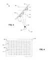
- FIG. 4illustrates a reflective scattering surface 400 including reflective scattering elements 405 , in accordance with an embodiment of the invention.
- Reflective scattering surface 400is one possible implementation of array 310 (see FIG. 3 ) or display region 115 (see FIG. 1 ).
- the illustrated embodiment of reflective scattering surface 400includes a regular or uniform periodic spacing between reflective scattering elements 405 to reflect an image output from light source 305 back towards the same side of transparent substrate 320 from which the light is projected. This permits the viewer (e.g., driver 130 ) and light source 305 to be positioned on the same side of transparent substrate 320 .
- each reflective scattering element 405Due to the curvature of the reflective surface of each reflective scattering element 405 , the light is reflected with a relative high angle of divergence so that it can be perceived from a wide angle of positions.
- Each reflective scattering element 405can be thought of as reflecting a single pixel of the image painted onto transparent substrate 320 .
- the interstitial regions 410 between each reflective scattering element 405permits external light 340 to pass through so that the pixilated reflected image is perceived as being painted over the external scene.
- each reflective scattering element 405may have a diameter of approximately 200 ⁇ m and be offset from an adjacent element by an interstitial gap 410 of approximately 200 ⁇ m. Of course, other dimensions may be used.
- FIG. 4illustrates reflective scattering surface 400 as having a uniform periodic spacing, other embodiments may use a non-regular spacing or a randomized spacing.
- FIG. 5illustrates a reflective scattering surface 500 having non-uniform spacing between reflective scattering elements 505 to form a reflective diffraction grid, in accordance with an embodiment of the invention.
- Reflective scattering surface 500is one possible implementation of array 310 (see FIG. 3 ) or display region 115 (see FIG. 1 ). However, instead of illuminating reflective scattering surface 500 with an image, reflective scattering surface 500 is illuminated with uniform laser light having a fixed wavelength.
- the size of elements 505 and/or the size of the interstitial spacing 510 between elements 505may be selected to be on the same order of magnitude as the wavelength of the laser light, which results in diffraction.
- the non-uniform pattern or diffraction gridcan be specified such that the diffraction grid will reflect a fixed image in response to uniform illumination by laser light.
- Diffraction grid patterns using reflective scattering elements 505can be designed to generate nearly any image in response to illumination by laser light.
- the size of either or both of elements 505 and interstitial spacing 510will have variable non-uniform size across reflective scattering surface 500 .
- FIG. 6illustrates how a plurality of display regions can be positioned at different locations on windshield 105 to display various information, in accordance with an embodiment of the invention.
- windshield 105may include multiple display regions 600 A-E (collectively display regions 600 ) positioned anywhere on windshield 105 .
- Each display region 600represent one possible implementation of display region 115 illustrated in FIG. 1 .
- display regions 600may be implemented using reflective scattering surfaces 400 or 500 .
- windshield 105may include a mix of reflective scattering surfaces 400 and 500 .
- the various display regions 600may be illuminated with a single light source 110 where optical splitters and various types of light guides or reflectors are used to selectively direct the light output from a single light source to the various display regions 600 .
- each display region 600may be illuminated by its own associated light source 115 .
- the various display regions 600may be used to display vehicle/navigation information such as speed, engine RPM, fuel, music information, navigation prompts, compass information, caller ID, etc.
- navigation promptsmay include first and second diffraction grids that display left and right pointing arrows, respectively (e.g., display regions 600 C and 600 D), when illuminated. These arrows may be illuminated in response to a navigation system to provide turning cues to driver 130 .
- the illumination lightmay include an image (e.g., a CGI) for reflection towards the driver and/or passenger(s).
- the illumination lightmay be regular laser light.
- the array of reflective scattering elementsmay organize the individual reflective scattering elements such that the overall shape of the array assumes the shape of the given image.
- multi-colored laser lightmay be used to generate multi-colored images.
- FIG. 7illustrates an example image that can be illuminated within one or more display regions on a windshield, in accordance with an embodiment of the invention.
- FIG. 7illustrates two digital number displays 705 and 710 .
- Each digital number displayis made up of three horizontal bars and four vertical bars.
- each horizontal or vertical barmay represent an independent display region within windshield 105 having its own array of reflective scattering elements.
- each horizontal or vertical barmay include its own reflective scattering surface 400 or 500 .
- a given baris not illuminated, it is virtually imperceptible to the driver and passenger(s); however, a given bar will appear to the driver and/or passenger(s) upon illumination of its associate array of reflective scattering elements. In this manner, variable alpha-numeric information can be painted onto windshield 105 in a dynamic manner.
- FIG. 8is a functional block diagram of a light source 800 for use with array 310 of reflective scattering elements 315 disposed on a transparent substrate 320 , in accordance with an embodiment of the invention.
- Light source 800represents one possible implementation of light source 110 in FIG. 2 or light source 305 in FIG. 3 .
- the illustrated embodiment of light source 800includes a laser source 805 , optics 810 , a diffraction element 815 , a pulse generator 820 , an actuator 825 , and a synchronization circuit 830 .
- Diffraction element 815is a substrate that includes a plurality of individual diffraction gratings (e.g., diffraction gratings D 1 , D 2 , D 3 , D 4 , D 5 . . . Dn) physically present on the substrate.
- Each diffraction gratingis configured to generate a different image when laser light output from laser source 805 passes through it.
- diffraction gratings D 1 -Dnrepresent optically transmissive diffraction gratings in contrast to a reflective diffraction grid, such as array 310 .
- Optics 810may include an expansion lens to expand a cross-section of the laser light to cover an entire individual diffraction grating at a time.
- array 310 of reflective scattering elements 315When the laser light passes through a given diffraction grating, an image is projected onto the surface of transparent substrate 320 where array 310 is positioned. Array 310 of reflective scattering elements 315 then reflects and scatters the diffraction image towards the viewer(s) (e.g., driver 130 and/or the passenger). However, in this embodiment the individual sizes of reflective scattering elements 315 and their interstitial regions are sufficiently large so as not to cause diffraction rather than scattered reflection.
- Actuator 825is mechanically coupled to diffraction element 815 to physically move diffraction element 815 to select a given diffraction grating.
- Diffraction element 815may assume a variety of shapes such as a disc with the diffraction gratings positioned radially around the disc, a plate with the diffraction gratings aligned in a linear one-dimensional array, a plate with the diffraction gratings aligned in two-dimensional array, or otherwise.
- actuator 825may be implemented in a variety of different manners based upon the geometry of how diffraction element 815 organizes the diffraction gratings.
- actuator 825may rotate diffraction element 815 or translate diffraction element 815 in one or two dimensions.
- Actuator 825may be implemented using various different devices, such as a servomechanism, a microelectromechanical system (MEMS) device, a voltage controlled actuator, a magnetically controlled actuator, or otherwise.
- MEMSmicroelectromechanical system
- synchronization circuit 830is coupled to actuator 825 and pulse generator 820 to synchronize the re-alignments with laser pulsation.
- Laser source 805may be pulse at a fixed rate with the inter-pulse durations used for re-alignment.
- actuator 825may reposition diffraction element 815 and when the laser source 805 is turned on, realignment position should already be achieved.
- laser source 805may be repeatedly pulsed through the selected diffraction grating.
- the pulsation ratemay be increased to provide better image quality (reduced flicker) and decreased when realignment is necessary.
- a fixed pulsation ratemay be used.
Landscapes
- Physics & Mathematics (AREA)
- General Physics & Mathematics (AREA)
- Optics & Photonics (AREA)
- Instrument Panels (AREA)
Abstract
Description
Claims (8)
Priority Applications (1)
| Application Number | Priority Date | Filing Date | Title |
|---|---|---|---|
| US13/345,105US9329388B1 (en) | 2011-04-28 | 2012-01-06 | Heads-up display for a large transparent substrate |
Applications Claiming Priority (2)
| Application Number | Priority Date | Filing Date | Title |
|---|---|---|---|
| US201161480130P | 2011-04-28 | 2011-04-28 | |
| US13/345,105US9329388B1 (en) | 2011-04-28 | 2012-01-06 | Heads-up display for a large transparent substrate |
Publications (1)
| Publication Number | Publication Date |
|---|---|
| US9329388B1true US9329388B1 (en) | 2016-05-03 |
Family
ID=55807444
Family Applications (1)
| Application Number | Title | Priority Date | Filing Date |
|---|---|---|---|
| US13/345,105Active2033-09-15US9329388B1 (en) | 2011-04-28 | 2012-01-06 | Heads-up display for a large transparent substrate |
Country Status (1)
| Country | Link |
|---|---|
| US (1) | US9329388B1 (en) |
Cited By (7)
| Publication number | Priority date | Publication date | Assignee | Title |
|---|---|---|---|---|
| US20160124231A1 (en)* | 2013-06-28 | 2016-05-05 | Aisin Aw Co., Ltd. | Head-up display device |
| CN110275295A (en)* | 2018-03-14 | 2019-09-24 | 蒋晶 | Diffractive Display System |
| US10732408B2 (en)* | 2015-03-19 | 2020-08-04 | Fujifilm Corporation | Projection type display device and projection display method |
| CN111830707A (en)* | 2019-04-23 | 2020-10-27 | 宝马股份公司 | Display assembly for vehicles |
| US20210316611A1 (en)* | 2018-09-07 | 2021-10-14 | Audi Ag | Display apparatus comprising a self-illuminated screen element, motor vehicle comprising a display apparatus, and associated operating method |
| US11172179B2 (en)* | 2016-09-21 | 2021-11-09 | Nec Corporation | Projection system |
| US11799260B2 (en)* | 2020-10-08 | 2023-10-24 | Raytheon Company | System and method for zeroth-order diagnostic in spectral beam combining system |
Citations (57)
| Publication number | Priority date | Publication date | Assignee | Title |
|---|---|---|---|---|
| US4900133A (en) | 1988-10-27 | 1990-02-13 | Kaiser Electronics | Heads-up display combiner utilizing a cholesteric liquid crystal element |
| US5093567A (en) | 1989-07-14 | 1992-03-03 | Gec-Marconi Limited | Helmet systems with eyepiece and eye position sensing means |
| GB2272980A (en) | 1992-11-26 | 1994-06-01 | Electro Optics Ind Ltd | Optical beam splitting lens |
| WO1996005533A1 (en) | 1994-08-10 | 1996-02-22 | Lawrence Vandewalle | Method and apparatus for direct retinal projection |
| US5539422A (en) | 1993-04-12 | 1996-07-23 | Virtual Vision, Inc. | Head mounted display system |
| US5696521A (en) | 1994-06-22 | 1997-12-09 | Astounding Technologies (M) Sdn. Bhd. | Video headset |
| US5715337A (en) | 1996-09-19 | 1998-02-03 | The Mirco Optical Corporation | Compact display system |
| US5748377A (en) | 1995-10-26 | 1998-05-05 | Fujitsu Limited | Headup display |
| US5771124A (en) | 1996-07-02 | 1998-06-23 | Siliscape | Compact display system with two stage magnification and immersed beam splitter |
| US5815126A (en) | 1993-10-22 | 1998-09-29 | Kopin Corporation | Monocular portable communication and display system |
| US5844530A (en) | 1994-12-09 | 1998-12-01 | Kabushiki Kaisha Sega Enterprises | Head mounted display, and head mounted video display system |
| US5886822A (en) | 1996-10-08 | 1999-03-23 | The Microoptical Corporation | Image combining system for eyeglasses and face masks |
| US5896232A (en) | 1997-08-07 | 1999-04-20 | International Business Machines Corporation | Highly efficient and compact frontlighting for polarization-based reflection light valves |
| US5926318A (en) | 1998-04-06 | 1999-07-20 | Optimize Incorporated | Biocular viewing system with intermediate image planes for an electronic display device |
| US5943171A (en) | 1998-06-03 | 1999-08-24 | International Business Machines Corporation | Head mounted displays utilizing reflection light valves |
| US5949583A (en) | 1992-02-07 | 1999-09-07 | I-O Display Systems Llc | Head-mounted display with image generator, fold mirror and mirror for transmission to the eye position of the user |
| US6023372A (en) | 1997-10-30 | 2000-02-08 | The Microoptical Corporation | Light weight, compact remountable electronic display device for eyeglasses or other head-borne eyewear frames |
| US6091546A (en) | 1997-10-30 | 2000-07-18 | The Microoptical Corporation | Eyeglass interface system |
| US6172657B1 (en) | 1996-02-26 | 2001-01-09 | Seiko Epson Corporation | Body mount-type information display apparatus and display method using the same |
| US6201629B1 (en) | 1997-08-27 | 2001-03-13 | Microoptical Corporation | Torsional micro-mechanical mirror system |
| US6204974B1 (en) | 1996-10-08 | 2001-03-20 | The Microoptical Corporation | Compact image display system for eyeglasses or other head-borne frames |
| US6222677B1 (en) | 1999-04-12 | 2001-04-24 | International Business Machines Corporation | Compact optical system for use in virtual display applications |
| US6236511B1 (en)* | 2000-03-20 | 2001-05-22 | Rockwell Collins, Inc. | Beam combining optical element |
| US6353503B1 (en) | 1999-06-21 | 2002-03-05 | The Micropitical Corporation | Eyeglass display lens system employing off-axis optical design |
| US20030090439A1 (en) | 2001-09-07 | 2003-05-15 | Spitzer Mark B. | Light weight, compact, remountable face-supported electronic display |
| US6618099B1 (en) | 1999-06-21 | 2003-09-09 | The Microoptical Corporation | Display device with eyepiece assembly and display on opto-mechanical support |
| US6690516B2 (en) | 2000-01-31 | 2004-02-10 | Fujitsu Limited | Head mount type display device |
| US6701038B2 (en) | 2001-03-05 | 2004-03-02 | The Microoptical Corporation | Micro-electromechanical optical switch assembly for optical data networks |
| US6724354B1 (en) | 1999-06-21 | 2004-04-20 | The Microoptical Corporation | Illumination systems for eyeglass and facemask display systems |
| US6738535B2 (en) | 2001-01-31 | 2004-05-18 | International Business Machines Corporation | Head-mounted display content transformer |
| US6747611B1 (en) | 2000-07-27 | 2004-06-08 | International Business Machines Corporation | Compact optical system and packaging for head mounted display |
| US6829095B2 (en) | 2000-06-05 | 2004-12-07 | Lumus, Ltd. | Substrate-guided optical beam expander |
| US6879443B2 (en) | 2003-04-25 | 2005-04-12 | The Microoptical Corporation | Binocular viewing system |
| US20060192306A1 (en) | 2005-02-25 | 2006-08-31 | The Microoptical Corporation | Manufacturing methods for embedded optical system |
| US20060192307A1 (en) | 2005-02-25 | 2006-08-31 | Eugene Giller | Method for producing high quality optical parts by casting |
| US7158096B1 (en) | 1999-06-21 | 2007-01-02 | The Microoptical Corporation | Compact, head-mountable display device with suspended eyepiece assembly |
| US7203005B2 (en) | 2002-05-22 | 2007-04-10 | Chelix Technologies, Inc. | Real image configuration for a high efficiency heads-up display (HUD) using a polarizing mirror and a polarization preserving screen |
| US7242527B2 (en) | 2005-03-22 | 2007-07-10 | The Microoptical Corporation | Optical system using total internal reflection images |
| US7391573B2 (en) | 2003-09-10 | 2008-06-24 | Lumus Ltd. | Substrate-guided optical devices |
| US20080219025A1 (en) | 2007-03-07 | 2008-09-11 | Spitzer Mark B | Bi-directional backlight assembly |
| US7436560B2 (en) | 2004-12-30 | 2008-10-14 | Volkswagen Ag | Display device for a vehicle |
| US7457040B2 (en) | 2002-03-21 | 2008-11-25 | Lumus Ltd. | Light guide optical device |
| US20090122414A1 (en) | 2005-02-10 | 2009-05-14 | Lumus Ltd. | Substrate-Guided Optical Device Utilzing Thin Transparent Layer |
| US20090141501A1 (en)* | 2007-11-29 | 2009-06-04 | Sony Corporation | Image display apparatus |
| US20090160736A1 (en) | 2007-12-19 | 2009-06-25 | Hitachi, Ltd. | Automotive head up display apparatus |
| US20090201589A1 (en)* | 2007-09-10 | 2009-08-13 | Microvision, Inc. | Wide Field of View Head-Up Display System |
| US7577326B2 (en) | 2004-08-05 | 2009-08-18 | Lumus Ltd. | Optical device for light coupling |
| US7643214B2 (en) | 2004-06-17 | 2010-01-05 | Lumus Ltd. | Substrate-guided optical device with wide aperture |
| US7663805B2 (en) | 2007-10-09 | 2010-02-16 | Myvu Corporation | Eyewear display and media device interconnection system |
| US20100046070A1 (en) | 2008-08-21 | 2010-02-25 | Sony Corporation | Head-mounted display |
| US20100103078A1 (en) | 2008-10-23 | 2010-04-29 | Sony Corporation | Head-mounted display apparatus |
| US20100149073A1 (en) | 2008-11-02 | 2010-06-17 | David Chaum | Near to Eye Display System and Appliance |
| US20100253593A1 (en) | 2009-04-02 | 2010-10-07 | Gm Global Technology Operations, Inc. | Enhanced vision system full-windshield hud |
| US20100278480A1 (en) | 2009-04-21 | 2010-11-04 | Vasylyev Sergiy V | Light collection and illumination systems employing planar waveguide |
| US7900068B2 (en) | 2006-09-14 | 2011-03-01 | Hon Hai Precision Industry Co., Ltd. | Mobile multi-media interface and power pack for portable entertainment devices |
| US20110213664A1 (en) | 2010-02-28 | 2011-09-01 | Osterhout Group, Inc. | Local advertising content on an interactive head-mounted eyepiece |
| US8189263B1 (en)* | 2011-04-01 | 2012-05-29 | Google Inc. | Image waveguide with mirror arrays |
- 2012
- 2012-01-06USUS13/345,105patent/US9329388B1/enactiveActive
Patent Citations (70)
| Publication number | Priority date | Publication date | Assignee | Title |
|---|---|---|---|---|
| US4900133A (en) | 1988-10-27 | 1990-02-13 | Kaiser Electronics | Heads-up display combiner utilizing a cholesteric liquid crystal element |
| US5093567A (en) | 1989-07-14 | 1992-03-03 | Gec-Marconi Limited | Helmet systems with eyepiece and eye position sensing means |
| US5949583A (en) | 1992-02-07 | 1999-09-07 | I-O Display Systems Llc | Head-mounted display with image generator, fold mirror and mirror for transmission to the eye position of the user |
| GB2272980A (en) | 1992-11-26 | 1994-06-01 | Electro Optics Ind Ltd | Optical beam splitting lens |
| US5539422A (en) | 1993-04-12 | 1996-07-23 | Virtual Vision, Inc. | Head mounted display system |
| US5815126A (en) | 1993-10-22 | 1998-09-29 | Kopin Corporation | Monocular portable communication and display system |
| US5696521A (en) | 1994-06-22 | 1997-12-09 | Astounding Technologies (M) Sdn. Bhd. | Video headset |
| WO1996005533A1 (en) | 1994-08-10 | 1996-02-22 | Lawrence Vandewalle | Method and apparatus for direct retinal projection |
| US5844530A (en) | 1994-12-09 | 1998-12-01 | Kabushiki Kaisha Sega Enterprises | Head mounted display, and head mounted video display system |
| US5748377A (en) | 1995-10-26 | 1998-05-05 | Fujitsu Limited | Headup display |
| US6172657B1 (en) | 1996-02-26 | 2001-01-09 | Seiko Epson Corporation | Body mount-type information display apparatus and display method using the same |
| US5771124A (en) | 1996-07-02 | 1998-06-23 | Siliscape | Compact display system with two stage magnification and immersed beam splitter |
| US5715337A (en) | 1996-09-19 | 1998-02-03 | The Mirco Optical Corporation | Compact display system |
| US6384982B1 (en) | 1996-10-08 | 2002-05-07 | The Microoptical Corporation | Compact image display system for eyeglasses or other head-borne frames |
| US6356392B1 (en) | 1996-10-08 | 2002-03-12 | The Microoptical Corporation | Compact image display system for eyeglasses or other head-borne frames |
| US5886822A (en) | 1996-10-08 | 1999-03-23 | The Microoptical Corporation | Image combining system for eyeglasses and face masks |
| US6204974B1 (en) | 1996-10-08 | 2001-03-20 | The Microoptical Corporation | Compact image display system for eyeglasses or other head-borne frames |
| US5896232A (en) | 1997-08-07 | 1999-04-20 | International Business Machines Corporation | Highly efficient and compact frontlighting for polarization-based reflection light valves |
| US6353492B2 (en) | 1997-08-27 | 2002-03-05 | The Microoptical Corporation | Method of fabrication of a torsional micro-mechanical mirror system |
| US6538799B2 (en) | 1997-08-27 | 2003-03-25 | The Microoptical Corporation | Magnetically actuated torsional micro-mechanical mirror system |
| US6201629B1 (en) | 1997-08-27 | 2001-03-13 | Microoptical Corporation | Torsional micro-mechanical mirror system |
| US6023372A (en) | 1997-10-30 | 2000-02-08 | The Microoptical Corporation | Light weight, compact remountable electronic display device for eyeglasses or other head-borne eyewear frames |
| US6091546A (en) | 1997-10-30 | 2000-07-18 | The Microoptical Corporation | Eyeglass interface system |
| US6349001B1 (en) | 1997-10-30 | 2002-02-19 | The Microoptical Corporation | Eyeglass interface system |
| US5926318A (en) | 1998-04-06 | 1999-07-20 | Optimize Incorporated | Biocular viewing system with intermediate image planes for an electronic display device |
| US5943171A (en) | 1998-06-03 | 1999-08-24 | International Business Machines Corporation | Head mounted displays utilizing reflection light valves |
| US6222677B1 (en) | 1999-04-12 | 2001-04-24 | International Business Machines Corporation | Compact optical system for use in virtual display applications |
| US6353503B1 (en) | 1999-06-21 | 2002-03-05 | The Micropitical Corporation | Eyeglass display lens system employing off-axis optical design |
| US7843403B2 (en) | 1999-06-21 | 2010-11-30 | Myvu Corporation | Compact, head-mountable display device with suspended eyepiece assembly |
| US6618099B1 (en) | 1999-06-21 | 2003-09-09 | The Microoptical Corporation | Display device with eyepiece assembly and display on opto-mechanical support |
| US7158096B1 (en) | 1999-06-21 | 2007-01-02 | The Microoptical Corporation | Compact, head-mountable display device with suspended eyepiece assembly |
| US6724354B1 (en) | 1999-06-21 | 2004-04-20 | The Microoptical Corporation | Illumination systems for eyeglass and facemask display systems |
| US6690516B2 (en) | 2000-01-31 | 2004-02-10 | Fujitsu Limited | Head mount type display device |
| US6236511B1 (en)* | 2000-03-20 | 2001-05-22 | Rockwell Collins, Inc. | Beam combining optical element |
| US6829095B2 (en) | 2000-06-05 | 2004-12-07 | Lumus, Ltd. | Substrate-guided optical beam expander |
| US6747611B1 (en) | 2000-07-27 | 2004-06-08 | International Business Machines Corporation | Compact optical system and packaging for head mounted display |
| US6738535B2 (en) | 2001-01-31 | 2004-05-18 | International Business Machines Corporation | Head-mounted display content transformer |
| US6701038B2 (en) | 2001-03-05 | 2004-03-02 | The Microoptical Corporation | Micro-electromechanical optical switch assembly for optical data networks |
| US20030090439A1 (en) | 2001-09-07 | 2003-05-15 | Spitzer Mark B. | Light weight, compact, remountable face-supported electronic display |
| US7457040B2 (en) | 2002-03-21 | 2008-11-25 | Lumus Ltd. | Light guide optical device |
| US8004765B2 (en) | 2002-03-21 | 2011-08-23 | Lumus Ltd. | Light guide optical device |
| US7724441B2 (en) | 2002-03-21 | 2010-05-25 | Lumus Ltd. | Light guide optical device |
| US7576916B2 (en) | 2002-03-21 | 2009-08-18 | Lumus Ltd. | Light guide optical device |
| US7203005B2 (en) | 2002-05-22 | 2007-04-10 | Chelix Technologies, Inc. | Real image configuration for a high efficiency heads-up display (HUD) using a polarizing mirror and a polarization preserving screen |
| US6879443B2 (en) | 2003-04-25 | 2005-04-12 | The Microoptical Corporation | Binocular viewing system |
| US20050174651A1 (en) | 2003-04-25 | 2005-08-11 | The Microoptical Corporation | Binocular viewing system |
| US7391573B2 (en) | 2003-09-10 | 2008-06-24 | Lumus Ltd. | Substrate-guided optical devices |
| US7724442B2 (en) | 2003-09-10 | 2010-05-25 | Lumus Ltd. | Substrate-guided optical devices |
| US7672055B2 (en) | 2003-09-10 | 2010-03-02 | Lumus Ltd. | Substrate-guided optical devices |
| US7643214B2 (en) | 2004-06-17 | 2010-01-05 | Lumus Ltd. | Substrate-guided optical device with wide aperture |
| US7577326B2 (en) | 2004-08-05 | 2009-08-18 | Lumus Ltd. | Optical device for light coupling |
| US7436560B2 (en) | 2004-12-30 | 2008-10-14 | Volkswagen Ag | Display device for a vehicle |
| US20090122414A1 (en) | 2005-02-10 | 2009-05-14 | Lumus Ltd. | Substrate-Guided Optical Device Utilzing Thin Transparent Layer |
| US7724443B2 (en) | 2005-02-10 | 2010-05-25 | Lumus Ltd. | Substrate-guided optical device utilizing thin transparent layer |
| US20060192306A1 (en) | 2005-02-25 | 2006-08-31 | The Microoptical Corporation | Manufacturing methods for embedded optical system |
| US20060192307A1 (en) | 2005-02-25 | 2006-08-31 | Eugene Giller | Method for producing high quality optical parts by casting |
| US7242527B2 (en) | 2005-03-22 | 2007-07-10 | The Microoptical Corporation | Optical system using total internal reflection images |
| US7900068B2 (en) | 2006-09-14 | 2011-03-01 | Hon Hai Precision Industry Co., Ltd. | Mobile multi-media interface and power pack for portable entertainment devices |
| US20080219025A1 (en) | 2007-03-07 | 2008-09-11 | Spitzer Mark B | Bi-directional backlight assembly |
| US20090201589A1 (en)* | 2007-09-10 | 2009-08-13 | Microvision, Inc. | Wide Field of View Head-Up Display System |
| US7663805B2 (en) | 2007-10-09 | 2010-02-16 | Myvu Corporation | Eyewear display and media device interconnection system |
| US20090141501A1 (en)* | 2007-11-29 | 2009-06-04 | Sony Corporation | Image display apparatus |
| US20090160736A1 (en) | 2007-12-19 | 2009-06-25 | Hitachi, Ltd. | Automotive head up display apparatus |
| US20100046070A1 (en) | 2008-08-21 | 2010-02-25 | Sony Corporation | Head-mounted display |
| US20100103078A1 (en) | 2008-10-23 | 2010-04-29 | Sony Corporation | Head-mounted display apparatus |
| US20100149073A1 (en) | 2008-11-02 | 2010-06-17 | David Chaum | Near to Eye Display System and Appliance |
| US20100253593A1 (en) | 2009-04-02 | 2010-10-07 | Gm Global Technology Operations, Inc. | Enhanced vision system full-windshield hud |
| US20100278480A1 (en) | 2009-04-21 | 2010-11-04 | Vasylyev Sergiy V | Light collection and illumination systems employing planar waveguide |
| US20110213664A1 (en) | 2010-02-28 | 2011-09-01 | Osterhout Group, Inc. | Local advertising content on an interactive head-mounted eyepiece |
| US8189263B1 (en)* | 2011-04-01 | 2012-05-29 | Google Inc. | Image waveguide with mirror arrays |
Non-Patent Citations (2)
| Title |
|---|
| Levola, Tapani, "Diffractive Optics for Virtual Reality Displays", Academic Dissertation, Joensuu 2005, University of Joensuu, Department of Physics, Vaisala Laboratory, 26 pages. |
| Mukawa, Hiroshi et al., "Distinguished Paper: A Full Color Eyewear Display using Holographic Planar Waveguides", SID Symposium Digest of Technical Papers-May 2008-vol. 39, Issue 1, pp. 89-92. |
Cited By (11)
| Publication number | Priority date | Publication date | Assignee | Title |
|---|---|---|---|---|
| US20160124231A1 (en)* | 2013-06-28 | 2016-05-05 | Aisin Aw Co., Ltd. | Head-up display device |
| US9946078B2 (en)* | 2013-06-28 | 2018-04-17 | Aisin Aw Co., Ltd. | Head-up display device |
| US10732408B2 (en)* | 2015-03-19 | 2020-08-04 | Fujifilm Corporation | Projection type display device and projection display method |
| US11172179B2 (en)* | 2016-09-21 | 2021-11-09 | Nec Corporation | Projection system |
| CN110275295A (en)* | 2018-03-14 | 2019-09-24 | 蒋晶 | Diffractive Display System |
| US20210003839A1 (en)* | 2018-03-14 | 2021-01-07 | Jing Jiang | Diffraction display system |
| US20210316611A1 (en)* | 2018-09-07 | 2021-10-14 | Audi Ag | Display apparatus comprising a self-illuminated screen element, motor vehicle comprising a display apparatus, and associated operating method |
| US11932107B2 (en)* | 2018-09-07 | 2024-03-19 | Audi Ag | Display apparatus comprising a self-illuminated screen element, motor vehicle comprising a display apparatus, and associated operating method |
| CN111830707A (en)* | 2019-04-23 | 2020-10-27 | 宝马股份公司 | Display assembly for vehicles |
| CN111830707B (en)* | 2019-04-23 | 2022-09-02 | 宝马股份公司 | Display assembly for vehicle |
| US11799260B2 (en)* | 2020-10-08 | 2023-10-24 | Raytheon Company | System and method for zeroth-order diagnostic in spectral beam combining system |
Similar Documents
| Publication | Publication Date | Title |
|---|---|---|
| US9329388B1 (en) | Heads-up display for a large transparent substrate | |
| US11977227B2 (en) | Methods and devices for data projection | |
| JP7397925B2 (en) | Vehicle information display device and vehicle information display system | |
| CN103454704B (en) | Display packing | |
| CN109143576B (en) | Display system, display method thereof and vehicle | |
| CN109031676B (en) | Projection device, head-up display equipment and vehicle-mounted vision auxiliary system | |
| CN104090369B (en) | Head-up display | |
| US20060215244A1 (en) | Vehicle display system | |
| WO2020149078A1 (en) | Vehicular information display system and information display device | |
| CN114326118B (en) | A multi-focus image generating device, a head-up display device, and related methods and equipment | |
| KR102452391B1 (en) | Multiple viewing angle monitor system using a transparent optical lens with recorded optical pattern | |
| Hedili et al. | Microstructured head-up display screen for automotive applications | |
| JP7587417B2 (en) | Space floating image display device and light source device | |
| JP2023525844A (en) | Multifocal plane image generation device, head-up display device, related methods and devices | |
| WO2020203767A1 (en) | Information display system and vehicle information display system using this | |
| JP5333782B2 (en) | Head-up display device | |
| JP2011180177A (en) | Head-up display apparatus | |
| WO2024219307A1 (en) | Projection device | |
| KR20250099410A (en) | Compact, wide-field windshield head-up display with hybrid reflective mid-image screen | |
| Wu et al. | An Augmented Reality Head‐Up Display System with a Wide‐View Eyebox | |
| JP6331839B2 (en) | Head-up display device | |
| CN114690411B (en) | Vehicle-mounted imaging device based on MEMS array | |
| CN216622850U (en) | Multi-depth head-up display system and vehicle-mounted system | |
| CN115097635B (en) | Head-up display device | |
| CN214751108U (en) | Vehicle-mounted imaging device based on MEMS array |
Legal Events
| Date | Code | Title | Description |
|---|---|---|---|
| AS | Assignment | Owner name:GOOGLE INC., CALIFORNIA Free format text:ASSIGNMENT OF ASSIGNORS INTEREST;ASSIGNOR:AMIRPARVIZ, BABAK;REEL/FRAME:027496/0049 Effective date:20120103 | |
| STCF | Information on status: patent grant | Free format text:PATENTED CASE | |
| AS | Assignment | Owner name:WAYMO HOLDING INC., CALIFORNIA Free format text:ASSIGNMENT OF ASSIGNORS INTEREST;ASSIGNOR:GOOGLE INC.;REEL/FRAME:042099/0935 Effective date:20170321 | |
| AS | Assignment | Owner name:WAYMO LLC, CALIFORNIA Free format text:ASSIGNMENT OF ASSIGNORS INTEREST;ASSIGNOR:WAYMO HOLDING INC.;REEL/FRAME:042108/0021 Effective date:20170322 | |
| AS | Assignment | Owner name:GOOGLE LLC, CALIFORNIA Free format text:CHANGE OF NAME;ASSIGNOR:GOOGLE INC.;REEL/FRAME:044142/0357 Effective date:20170929 | |
| AS | Assignment | Owner name:WAYMO LLC, CALIFORNIA Free format text:ASSIGNMENT OF ASSIGNORS INTEREST;ASSIGNOR:WAYMO HOLDING INC.;REEL/FRAME:047571/0274 Effective date:20170322 | |
| AS | Assignment | Owner name:GOOGLE LLC, CALIFORNIA Free format text:CORRECTIVE ASSIGNMENT TO CORRECT THE CORRECTIVE BY NULLIFICATIONTO CORRECT INCORRECTLY RECORDED APPLICATION NUMBERS PREVIOUSLY RECORDED ON REEL 044142 FRAME 0357. ASSIGNOR(S) HEREBY CONFIRMS THE CHANGE OF NAME;ASSIGNOR:GOOGLE INC.;REEL/FRAME:047837/0678 Effective date:20170929 | |
| MAFP | Maintenance fee payment | Free format text:PAYMENT OF MAINTENANCE FEE, 4TH YEAR, LARGE ENTITY (ORIGINAL EVENT CODE: M1551); ENTITY STATUS OF PATENT OWNER: LARGE ENTITY Year of fee payment:4 | |
| AS | Assignment | Owner name:WAYMO LLC, CALIFORNIA Free format text:SUBMISSION TO CORRECT AN ERROR MADE IN A PREVIOUSLY RECORDED DOCUMENT THAT ERRONEOUSLY AFFECTS THE IDENTIFIED APPLICATIONS;ASSIGNOR:WAYMO LLC;REEL/FRAME:051093/0861 Effective date:20191001 | |
| MAFP | Maintenance fee payment | Free format text:PAYMENT OF MAINTENANCE FEE, 8TH YEAR, LARGE ENTITY (ORIGINAL EVENT CODE: M1552); ENTITY STATUS OF PATENT OWNER: LARGE ENTITY Year of fee payment:8 |