US9329332B2 - Light pipe illumination system and method - Google Patents
Light pipe illumination system and methodDownload PDFInfo
- Publication number
- US9329332B2 US9329332B2US14/316,906US201414316906AUS9329332B2US 9329332 B2US9329332 B2US 9329332B2US 201414316906 AUS201414316906 AUS 201414316906AUS 9329332 B2US9329332 B2US 9329332B2
- Authority
- US
- United States
- Prior art keywords
- light pipe
- light
- illumination
- subject
- field
- Prior art date
- Legal status (The legal status is an assumption and is not a legal conclusion. Google has not performed a legal analysis and makes no representation as to the accuracy of the status listed.)
- Expired - Fee Related
Links
Images


Classifications
- G—PHYSICS
- G02—OPTICS
- G02B—OPTICAL ELEMENTS, SYSTEMS OR APPARATUS
- G02B6/00—Light guides; Structural details of arrangements comprising light guides and other optical elements, e.g. couplings
- G02B6/0001—Light guides; Structural details of arrangements comprising light guides and other optical elements, e.g. couplings specially adapted for lighting devices or systems
- G02B6/0096—Light guides; Structural details of arrangements comprising light guides and other optical elements, e.g. couplings specially adapted for lighting devices or systems the lights guides being of the hollow type
- G—PHYSICS
- G06—COMPUTING OR CALCULATING; COUNTING
- G06K—GRAPHICAL DATA READING; PRESENTATION OF DATA; RECORD CARRIERS; HANDLING RECORD CARRIERS
- G06K7/00—Methods or arrangements for sensing record carriers, e.g. for reading patterns
- G06K7/10—Methods or arrangements for sensing record carriers, e.g. for reading patterns by electromagnetic radiation, e.g. optical sensing; by corpuscular radiation
- G06K7/10544—Methods or arrangements for sensing record carriers, e.g. for reading patterns by electromagnetic radiation, e.g. optical sensing; by corpuscular radiation by scanning of the records by radiation in the optical part of the electromagnetic spectrum
- G06K7/10712—Fixed beam scanning
- G06K7/10722—Photodetector array or CCD scanning
- G06K7/10732—Light sources
- G—PHYSICS
- G06—COMPUTING OR CALCULATING; COUNTING
- G06K—GRAPHICAL DATA READING; PRESENTATION OF DATA; RECORD CARRIERS; HANDLING RECORD CARRIERS
- G06K7/00—Methods or arrangements for sensing record carriers, e.g. for reading patterns
- G06K7/10—Methods or arrangements for sensing record carriers, e.g. for reading patterns by electromagnetic radiation, e.g. optical sensing; by corpuscular radiation
- G06K7/14—Methods or arrangements for sensing record carriers, e.g. for reading patterns by electromagnetic radiation, e.g. optical sensing; by corpuscular radiation using light without selection of wavelength, e.g. sensing reflected white light
- G06K7/1404—Methods for optical code recognition
- G—PHYSICS
- G06—COMPUTING OR CALCULATING; COUNTING
- G06K—GRAPHICAL DATA READING; PRESENTATION OF DATA; RECORD CARRIERS; HANDLING RECORD CARRIERS
- G06K7/00—Methods or arrangements for sensing record carriers, e.g. for reading patterns
- G06K7/10—Methods or arrangements for sensing record carriers, e.g. for reading patterns by electromagnetic radiation, e.g. optical sensing; by corpuscular radiation
- G06K2007/10485—Arrangement of optical elements
- G—PHYSICS
- G06—COMPUTING OR CALCULATING; COUNTING
- G06K—GRAPHICAL DATA READING; PRESENTATION OF DATA; RECORD CARRIERS; HANDLING RECORD CARRIERS
- G06K2207/00—Other aspects
- G06K2207/1011—Aiming
Definitions
- This inventionrelates to illuminators and more particularly to illuminators for image acquisition devices and machine vision systems.
- Machine vision systemsuse image acquisition devices that include camera sensors to deliver information on a viewed subject. The system then interprets this information according to a variety of algorithms to perform a programmed decision-making and/or identification function. For an image to be most-effectively acquired by a sensor in the visible, and near-visible light range, the subject should be properly illuminated.
- Barcode scanningentails the aiming of an image acquisition sensor (CMOS camera, CCD, etc.) at a location on an object that contains a bar code, and retrieval of an image of that barcode.
- the bar codecontains a set of predetermined patterns that represent an ordered group of characters or symbols from which an attached data processor (for example a microcomputer) can derive useful information about the object (e.g., its serial number, type, model, price, etc.).
- Barcodesare available in a variety of shapes and sizes. Two of the most commonly employed barcode types are the so-called one-dimensional barcode, consisting a line of vertical stripes of varying width and spacing, and the so-called two-dimensional barcode consisting of a two-dimensional array of dots or rectangles.
- a diffuse, high-angle “bright field” illuminationmay best highlight these features for the sensor.
- high-angleit is meant, generally, light that strikes the subject nearly perpendicularly (normal) or at an angle that is typically no less than about 45 degrees from perpendicular (normal) to the surface of the item being scanned.
- Such illuminationis subject to substantial reflection back toward the sensor.
- barcodes and other subjects requiring mainly bright field illuminationmay be present on a printed label adhered to an item or container, or on a printed field in a relatively smooth area of item or container.
- a peened/etched surfacehas two-dimensional properties that tend to scatter bright field illumination, thereby obscuring the acquired image.
- dark field illuminationThis is an illumination with a characteristic low angle (approximately 45 degrees or less, for example) with respect to the surface of the subject (i.e. an angle of more than approximately 45 degrees with respect to normal).
- a characteristic low angleapproximately 45 degrees or less, for example
- two-dimensional surface textureis contrasted more effectively (with indents appearing as bright spots and the surroundings as shadow) for better image acquisition.
- a current-production sensormay have a resolution of 640 ⁇ 480 (over 300 K) or 1280 ⁇ 1024 (over 1.3 M) pixels within its native field of view. This resolution is desirable for attaining an accurate image of the subject.
- processing speedmay be compromised by the need to acquire every pixel in the field of view even if the subject is a relatively small part of that field (for example, the narrow strip of a one-dimensional barcode). If the field of view is to be narrowed to only encompass an area of interest, then a system for aiming the camera onto that area of interest is desirable.
- a given field of viewmay contain multiple codes or subjects, the ability to focus upon particular parts of that field of view to discern the selected subject is also desirable.
- This inventionovercomes the disadvantages of the prior art by providing systems and methods for illuminating a subject using a light pipe that transmits light from a source, such as an LED ring illuminator to an outlet that directs the light appropriately as either bright field illumination, dark field illumination or both.
- the light pipecan include concentric or coaxial (nested) cylinders, typically with a bright field illuminator nested within a dark field illuminator.
- the tip of the dark field illuminatoris angled so as to internally reflect light inwardly toward the central optical axis of a camera at a low angle. The tip can be located near the focal plane of the camera for the desired field of view.
- the field of view of the camera sensorcan be modified to reject data outside of a illumination field of a particular shape.
- This illumination fieldcan be created by shaping the light pipe in a predetermined form that projects the modified illumination field.
- a set of aiming illuminatorsin, for example, a noticeable color
- aiming illuminatorscan be provided around the perimeter of the light pipe to delineate outer boundaries of the illumination field or area of interest.
- the present inventionprovides a method for illuminating a subject.
- the methodcomprises steps including providing a light pipe, the light pipe defining an inner lumen through which the image sensor views the subject; providing a light source in alignment with a proximal portion of the light pipe; and using the light source, projecting a light into the light pipe and through the light pipe, the light pipe including a distal portion for providing a high-angle bright field illumination pattern on the subject with a first portion of the light and for reflecting a second portion of the light for providing a low-angle dark field illumination pattern on the subject.
- the present inventionprovides a method for illuminating a subject that is imaged by an image sensor.
- the methodcomprises steps including providing a first ring light source arranged around a perimeter of a predetermined shape, the first ring light source projecting light into a first light pipe defining a hollow tube having a cross-section with the predetermined shape, the first light pipe defining an inner lumen through which the image sensor views the subject and the light pipe including a tip for projecting a low-angle dark field illumination pattern on the subject; and providing an electronic controller, the electronic controller selectively controlling predetermined portions of the first ring light source for projecting a variable light around the perimeter.
- the present inventionprovides a method for illuminating a subject that is imaged by an image sensor.
- the methodcomprises providing a ring light source arranged around a perimeter of a predetermined shape, the ring light source projecting light into a light pipe defining a hollow tube having a cross-section with the predetermined shape, the light pipe defining an inner lumen through which the image sensor views the subject and the light pipe including a tip to project a high-angle bright field illumination pattern with respect to the subject.
- the present inventionprovides a method for illuminating a subject that is imaged by an image sensor.
- the methodcomprises steps including providing a first ring light source arranged around a perimeter of a predetermined shape, the first ring light source projecting light into a first light pipe defining a hollow tube having a cross-section with the predetermined shape, the first light pipe defining an inner lumen through which the image sensor views the subject and the light pipe including a tip to project a low-angle dark field illumination pattern on the subject; and providing a bright field illuminator located external to the light pipe.
- FIG. 1is a perspective view of a handheld scanning system and subject employing a light pipe illuminator according to an embodiment of this invention
- FIG. 2is a perspective view of a fixedly mounted scanning system and subject employing a light pipe illuminator according to an embodiment of this invention
- FIG. 3is a schematic cross section of a light pipe and ring illuminator according to an embodiment of this invention.
- FIG. 4is a side cross section of a sensor with dark field illuminating light pipe according to an embodiment of this invention.
- FIG. 5is a side cross section of a sensor with bright field illuminating light pipe and aiming illuminators according to an embodiment of this invention
- FIG. 6is a plan view of a circular illumination pattern projected by the illuminating light pipe of FIG. 5 ;
- FIG. 7is a plan view of a rectangular/square illumination pattern projected by the illuminating light pipe of FIG. 5 , encompassing the sensor's full field of view;
- FIG. 8is a side cross section of a sensor with bright field illuminating light pipe, nested within a dark field illuminating light pipe and aiming illuminators according to an embodiment of this invention
- FIG. 9is a perspective view of a handheld scanning system employing a light pipe that illuminates a modified or restricted sensor field of view according to an alternate embodiment
- FIG. 10is a plan view of a rectangular illumination pattern projected by the illuminating light pipe of FIG. 9 , encompassing a modified/restricted sensor field of view;
- FIG. 11is a side cross section of the sensor and light pipe illuminator that can be used to generate a predetermined bright field pattern such as, for example that of FIG. 9 .
- FIG. 1shows a scanning system 100 adapted for handheld operation.
- An exemplary handheld scanning appliance or handpiece 102is provided. It includes a grip section 104 and a body section 106 .
- the sensor and other functional components described hereincan be controlled and can direct image data to an on-board/embedded processor 109 .
- This processorcan include a scanning software application 113 by which lighting is controlled, images are acquired and image data is interpreted into usable information (for example, alphanumeric strings derived from the barcode images).
- the decoded informationcan be directed via a cable 110 to a PC or other data storage device 112 having (for example) a display 114 , keyboard 116 and mouse 118 , where it can be stored and further manipulated using an appropriate application 120 .
- the cable 110can be directly connected to an interface in the scanning appliance and an appropriate interface in the computer 112 .
- the computer-based application 120performs various image interpretation and lighting control functions as needed.
- the precise arrangement of the handheld scanning appliance with respect to an embedded processor, computer or other processoris highly variable.
- a wireless interconnectcan be provided in which no cable 110 is present.
- the depicted microcomputercan be substituted with another processing device, including an on board processor or a miniaturized processing unit such as a personal digital assistant or other small-scale computing device.
- the scanning application 113can be adapted to respond to inputs from the scanning appliance 102 .
- an internal camera image sensor150 , shown and described further below
- the exemplary region of interestincludes a two-dimensional bar code 134 that can be used to identify the part 132 .
- Identification and other processing functionsare carried out by the scanning application 113 , based upon image data transmitted from the appliance 102 to the processor 109 .
- a switch 140 on the appliance 102can be used to operate the illuminator, which consists of a novel light pipe arrangement 142 in accordance with this invention.
- the operation of the illuminatorcan be operated and controlled remotely by the scanning software application 120 .
- the light pipe 142consists of an extended barrel of light transmissive material terminating (in this embodiment) in an angled tip 144 . As described further below, this tip is designed to cause internal reflection that projects a low-angle dark field illumination in the area of interest 130 .
- such dark field illuminationis typically provided at an angle of no more than approximately 45 degrees with respect to the surface or more than 45 degrees normal to the optical axis.
- a camera sensor 150shown in phantom and associated optics. The focal point of the camera is selected so that it is able to focus on the desired area of interest, as its field of view, in close proximity to the tip 144 . In this manner, the tip can be placed very close to, or in contact with the area of interest for accurate viewing.
- the bar code 134 in this embodimentis one that is best viewed using a dark field illumination.
- the light pipes described in accordance with this inventionalso has the ability to provide bright field illumination for bar codes that are better suited to direct, high-angle illumination (for example, those printed with high contrast ink on a relatively smooth, matte surface).
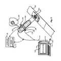
- FIG. 2shows another implementation of the light pipe in accordance with an embodiment of this invention.
- An embedded processor 109 and/or computer 112 and associated applications 113 and/or 120 similar to those described abovecan be employed.
- An associated cable 210interconnects the computer, via an interface, with a camera element 220 .
- the camera elementcan be a conventional camera mounted on a fixed bracket 222 . It includes a lens and electro-optical sensor assembly 224 (shown in phantom).
- the light pipeis removably mounted via a securing ring 226 with exemplary securing screws 228 in this embodiment. Note, while screws 228 are use, any fastener system can be substituted.
- a cable 230interconnects an internal ring illuminator, integral with light pipe, to either the processor 109 or the computer 112 .
- This arrangementallows the light pipes of this invention to be secured as a retrofit to a variety of preexisting cameras.
- the illuminatorcan be integrated with the camera's standard operating functions, such as its strobe and trigger mechanisms, or it can be controlled via the scanning application. Separate control circuitry can also be provided to modulate certain functions of the illuminator as described further below.
- the illuminatoris viewing parts or other items 216 moving along a conveyer 262 .
- the area of interest 264is a bar code that is best viewed using, for example, bright field illumination.
- the light pipe arrangementin accordance with the various embodiments of this invention, can accommodate bright field illumination as well as dark field illumination.
- the image sensoris, typically, a commercially available CMOS or CCD image sensor with a resolution of, for example, 640 ⁇ 480 pixels or 1280 ⁇ 1024 pixels. Other resolutions and sensor types are expressly contemplated, however.
- This light pipeincludes an outer tube 312 and a nested, inner tube 314 .
- the innermost wall of the inner tube 314defines, in this example, a circular lumen or channel.
- This channelis a path through which light can pass from the area of interest 320 to a board-mounted or separately placed sensor 330 .
- the lumenhas a diameter WL that is equal to or greater than the diameter of the optics of the camera sensor.
- the sensoris mounted on a circuit board 332 that also includes the ring illuminator 334 .
- This ring illuminatorconsists of an outer ring of LEDs or other appropriate light sources 336 and an inner ring 338 of LEDs or other appropriate light sources.
- the number of light sources, size of the rings and their shapeare highly variable.
- the term “ring”should be taken broadly to describe a variety of regular and irregular curved (ovular, etc.) and/or polygonal (rectangular, square, etc.) perimeter shapes.
- the ring illuminator's light sourcesare placed relatively close to the outer perimeter of the sensor and/or its optics and the number of sources is sufficient to fill in the illumination field and supply appropriate light to the subject.
- any group of light sources or one or more continuous sources (e.g., tubes) arranged to light a perimeter of any size/shapecan be broadly considered to be a “ring” light source herein.
- the ringcan define a circle that is approximately 3-4 inches in outer diameter.
- Each ringis aligned with respect to one of the light pipes 312 and 314 .
- appropriate bafflesseparate the rings from each other so that light from one ring does not leak into the other ring.
- each light pipeis constructed from a light-transmissive material.
- This materialcan be acrylic, glass, or any other material capable of acting as a wave guide for visible and near-visible light.
- the wall thickness of each pipemay vary. In general, thicknesses are between approximately 1 ⁇ 8 inch and 1 ⁇ 4 inch. However, larger or smaller thicknesses are expressly contemplated.
- the overall length of the outer light pipeis also highly variable. As noted above, it is set so that the focus on the desired field of view is attained near, but beyond, the end of the tip 340 . In one embodiment, the outer light pipe has a length of approximately 3-4 inches.
- the inner light pipe 314can be approximately the same length as the outer light pipe, but in this embodiment, the inner light pipe is recessed with respect to the outer, as shown, so that light can exit from the inner edge of the tip 340 .
- the tip's light-transmissive regionis shown by the dashed line 342 .
- This inner-edge light outletcan be formed by exposing and/or polishing a strip in the otherwise opaque overall surface of the outer light pipe 312 .
- This light transmissive strip or regioncan extend (for example) 1 ⁇ 4 inch, more or less, as shown by thickness T.
- the thickness Tis variable. Due to internal reflection caused by the angled portion 350 of the tip 340 , low angle illumination 352 exits from the open region 342 .
- the open tip 360 of the inner light pipe 314facilitates direct, bright field illumination 362 on the area of interest 320 .
- the mechanics of the nested light pipe 310are described in further detail below. Reference will first be made to FIG. 4 , which describes, more particularly, a dark field illuminator. Reference will also be made generally to the ring illuminator 334 and controller 370 of FIG. 3 .
- a single ring illuminator of LEDs or other light sources 410may be provided on a circuit board 412 along with a CMOS, CCD or other electro-optical sensor 414 .
- the sensoras described in any of the embodiments herein, may be separate from the light source's circuit board or combined with it.
- These elementsinterconnect to a controller and/or image acquisition processor similar to those shown in FIG. 3 .
- a dark field-illuminating light pipe 420is shown in cross-section. This surrounds the image sensor 414 and its associated optics 422 .
- a transparent window 424can be provided in front of the optics 422 to protect the circuitry.
- the tip 430 of the light pipe 420is angled at an angle A (approximately 45 degrees or more) so that light is reflected to pass through an exposed thickness T along the inner perimeter of the light pipe using internal reflection.
- the lighttransmits with the desired low-angle (or a high-angle (over 45 degrees) respect to optical axis centerline CL) dark field illumination patter 440 that, in this embodiment, is within a range DD of 0-1.25 inch.
- the angle A of the tip(approximately 45 degrees in this example) determines the general angular range of light exiting the tip. There tends to be a spread of angles, in fact, and the prevailing angle of light may vary somewhat from the angle of the tip.
- the angle A of the tipmay be altered to generate the best angle and spread for light based upon the material used for the light pipe and it's wall thickness.
- the dark field light sourcemay further include an external bright field illuminator 450 and/or 460 .
- the bright field illuminatoris a ring light source (with or without a light pipe) 450 that mayor may not be mounted on the circuit board 412 (see board extensions shown in phantom).
- the radial spacing of the optional, external bright field ringis variable. It may closely abut the dark field light pipe 420 , or may be spaced away from this light pipe as shown.
- a bright field illuminator 460may be provided at another external location or locations.
- the term “external” as used hereinshould be taken broadly to include a location that is inside the lumen of the dark field light pipe, such as, for example at the base of the pipe (adjacent to the circuit board, for example).
- This illuminatorcan be provided as the only bright field illuminator, or in addition to the bright field ring 450 .
- the controllerinterconnects with a number of segments of the LED ring.
- the depicted outer LED ring 336has four exemplary segments that represent the quadrants 380 , 382 , 384 and 386 of the overall circumference.
- the controller 370individually addresses each of the quadrants 380 - 386 .
- the quadrantscan be separately controlled/modulated. They can be turned on or off, or dimmed and brightened selectively to provide the best dark field illumination pattern for a particular subject. It has been observed that illumination of metallic and similar materials is often more effective when oriented along the grain of the material. With the ability to dim or deactivate illumination across the grain, a significantly improved image is attained.
- the scanning application or another image processorcan be used to determine the best lighting based upon the detected image's characteristics. This can entail a rapid cycling of light segments through a variety of preset on/off combinations until the best image quality is attained. This involves a feedback between the sensor, the scanning application and the LED controller. In other words, the sensor signal is processed by the scanning application for each different setting of the LEDs, and when an acceptable and/or optimal image is attained, that particular setting is chosen. Image optimization can be based upon recognition of known fiducials or detection of maximum contrast over a sufficiently wide portion of the viewed area of interest.
- this adjustment processcan be carried out once, and the selected setting can be applied to each successive acquired image.
- the adjustmentscan be made dynamically for each scan. Note that a fixed setting can also be chosen where the scan will always be taken from approximately the same location.
- any of the dark field illuminatorsincluding that shown in FIG. 4 , can include a ring illuminator enabling selectable control, with an associated LED controller. It is also expressly contemplated that the control of LEDs can be implemented in a variety of ways and with a wide range of ring segmentation options. While four segments are shown in the embodiment of FIG.
- each LEDmay be separately controllable/addressable in one embodiment to attain the desired dark field illumination pattern.
- the light pipecan include at least two nested (coaxial) light pipes for providing both dark field and bright field illumination in a single unit.
- the choice of whether dark field or bright field illumination best suits a particular subjectcan be made by the controller, image processor (automated) or by the operator (manual). According to an automated process, both bright field and dark field illumination can be attempted, and that which attains the best image quality is employed.
- a circuit board, 510carries LEDs 512 surrounding a sensor 514 with associated optics 516 and a window 518 to protect them.
- a light pipe 520communicates optically with the ring illuminator LEDs 512 .
- the tip 522 of the light pipe 520can be rounded or flat and can include a diffusing (frosted, for example) surface texture for enhanced scatter of bright field light. Note that other bright field light pipes described herein can have similar tip constructions and surfaces.
- the walls (inner and outer) of the light pipe 522can be coated with an opaque, non-transmissive material or can remain transmissive.
- each of a set of individual directing rods/lenses 530Surrounding the outer circumference of the light pipe 520 at various points are each of a set of individual directing rods/lenses 530 (shown in partial cross-section for clarity of rod-like structure) that each optically communicate with individual or clusters of LEDs 532 .
- the LEDs 532project aiming points, typically of a different, noticeable color onto the item of interest.
- the aiming LEDscan project a prominent blue, red or green dot while the overall illumination is a whitish light.
- the aiming point rods hereinare circular in cross section. However, they may be triangular, square or any other shape that adequately denotes an aiming point.
- FIGS. 6 and 7Two exemplary illumination patterns obtained with the bright field illuminator of FIG. 5 are shown, respectively in FIGS. 6 and 7 .
- the field of view of the camera sensorshown as a dashed line 602
- the circular bright field illuminatorprojects a circular illumination pattern 604 .
- the scanning application and/or image acquisition circuitrycan be set to reject data within these comers to speed processing.
- four aiming dots 610are provided around the perimeter of the illumination field 604 .
- aiming dotsgive instant feedback to the user so that he or she properly aims the illumination and field of view of the appliance onto the subject.
- a square illumination pattern 710is provided. This falls within the relative field of view 602 .
- aiming dots 712are used to ensure proper direction of the appliance by the user.
- the dark field illumination range DB1spans generally between approximately 0 and 12 inches from the tip 522 of the light pipe. Other ranges are contemplated, of course.
- FIG. 8shows, in further detail, a nested light pipe arrangement in accordance with an illustrative embodiment of this invention.
- An inner ring of LEDs 802 and an outer ring of LEDs 804are mounted on a circuit board 806 that also includes a sensor 810 .
- Associated optics for the sensor 812are provided within a window area 814 .
- the outer light pipe 820includes a tip 822 that is angled so as to produce, through an opening, thickness T an internally reflected beam of dark field illumination with a span DD2 having a range of 0-1.25 inch in one embodiment.
- the walls of the light pipe 820are coated with a non-transmissive, opaque coating and the LEDs 804 of the ring are sealed by baffles 830 that isolate this illumination source with respect to the inner LEDs 802 and associated inner bright field light pipe 840 .
- the bright field light pipeis nested within the dark field light pipe 820 and its tips 842 are recessed so as not to interfere with the opening thickness T.
- the tips 842can be rounded, angled or flat. They produce an appropriate bright field illumination pattern that, in this embodiment, can extend a distance DB2 from 0-6 inches with respect to the tip 822 of the dark field illuminator. In this manner, a bright field subject can be contacted by the appliance and still adequately illuminated.
- the inner diameter of the lumen formed by the light pipe assemblymust be at least as large in diameter as the subject being viewed. Nevertheless, in certain embodiments, it is contemplated that it is smaller and that the scanning application can include mechanisms for assembling portions of an image formed as the appliance is moved around the image to take in all aspects of it when it is larger than the maximum field of view afforded to the sensor.
- the controllercan determine either automatically or manually, whether to activate the dark field illumination ring LEDs 804 or the bright field illumination ring LEDs 802 depending upon the subject and/or image quality obtained.
- a set of perimeter LEDs 850communicate with lenses 852 in the form of rods that provide aiming dots as described above.
- FIG. 9shows a scanning appliance 902 having a rectangular cross-section light pipe 904 .
- This light pipecan either be a dark field or bright field (or combination) illuminator.
- an item 910includes a long, narrow subject 912 , namely a one-dimensional bar code.
- the illuminatorprojects a pattern similar in size and shape to the bar code itself. In this manner, when the user directs the illumination field to the item 910 , he or she is naturally prompted to align the rectangular illumination pattern with the bar code.
- the userreceives immediate feedback as to the location of the reduced field of view, which appears as a bright area that generally conforms to the subject outline.
- the subjectis better delineated by the reduced area, and any information outside this area can be omitted from the acquisition data stream, thus speeding image processing.
- the overall field of view of the camerashown as dashed line 1002 , is a large square while the illumination area is a substantially narrower rectangle 1004 .
- this rectangleconforms to the shape of a one-dimensional bar code in this example.
- a variety of other shapes and sizescan be provided for a selective illumination area with respect to the overall field of view. Small circles, ovals, squares and complex geometric patterns are all contemplated.
- Appropriately shaped light pipesare constructed to conform to these shapes.
- these light pipescan include dark field, bright field or a combination of bright and dark field structures as described above.
- the narrowed-field of view (or “reduced field of view”) illuminatorcan include aiming dots to further assist alignment on the subject.
- a ring of LEDs 1102is mounted on a circuit board 1104 , which also includes a sensor 1106 .
- the boardis interconnected with a controller or image acquisition device that includes scanning software applications.
- a bright field illumination patternextends a distance DB3 from the tip of the light pipe 1120 .
- the distance DB3is approximately 12 inches.
- the scanning software applicationis adapted to reject pixels outside of the desired field of view either through knowledge of pixel addresses that fall outside of the desired field or because these pixels are not appropriately illuminated and are therefore rejected (e.g., they are too dark).
- An appropriate optics 1110 and window 1112is also provided as well as a light pipe 1120 that is shaped as an elongated rectangle.
- the illuminator, light pipe and cameracan all be separate components that are interconnected via one or more controllers, or all connected to a common computer or processor through appropriate interfaces.
- Various combinations of sensor, optics, illuminator and light pipesare all expressly contemplated.
- sensorsmay be provided on the same circuit board as the processor and the light sources, or any/all of these components can be separate.
- Appropriate interfaces and attachment mechanismsthat should be clear to those of ordinary skill, can be provided to facilitate interaction between the various components described herein.
- the bright field light pipeis described as nested within the dark field light pipe, it is expressly contemplated that these two pipes can be reversed by positioning the bright field illuminator outside the dark field light pipe.
- either light pipe (or light source therefore)may be defined as a broken ring, with non-illuminated segments along their perimeters. Accordingly, this description is meant to be taken only by way of example and not to otherwise limit the scope of the invention.
Landscapes
- Physics & Mathematics (AREA)
- Engineering & Computer Science (AREA)
- Electromagnetism (AREA)
- General Physics & Mathematics (AREA)
- Artificial Intelligence (AREA)
- Toxicology (AREA)
- General Health & Medical Sciences (AREA)
- Computer Vision & Pattern Recognition (AREA)
- Health & Medical Sciences (AREA)
- Theoretical Computer Science (AREA)
- Optics & Photonics (AREA)
- Length Measuring Devices By Optical Means (AREA)
- Image Input (AREA)
- Stroboscope Apparatuses (AREA)
- Microscoopes, Condenser (AREA)
Abstract
Description
This application is a continuation of U.S. Patent application Ser. No. 13/623,336, filed Sep. 20, 2012, entitled “Light Pipe Illumination System and Method,” which is a continuation of U.S. patent application Ser. No. 13/294,286, filed Nov. 11, 2011, entitled “Light Pipe Illumination System and Method,” which is a continuation of U.S. patent application Ser. No. 12/900,593, filed on Oct. 8, 2010, entitled “Light Pipe Illumination System and Method,” which is a continuation of U.S. patent application Ser. No. 10/693,626, filed on Oct. 24, 2003, and entitled “Light Pipe Illumination System and Method,” each of which are hereby incorporated by reference.
This invention relates to illuminators and more particularly to illuminators for image acquisition devices and machine vision systems.
Machine vision systems use image acquisition devices that include camera sensors to deliver information on a viewed subject. The system then interprets this information according to a variety of algorithms to perform a programmed decision-making and/or identification function. For an image to be most-effectively acquired by a sensor in the visible, and near-visible light range, the subject should be properly illuminated.
In the example of barcode scanning using an image sensor, good lighting is highly desirable. Barcode scanning entails the aiming of an image acquisition sensor (CMOS camera, CCD, etc.) at a location on an object that contains a bar code, and retrieval of an image of that barcode. The bar code contains a set of predetermined patterns that represent an ordered group of characters or symbols from which an attached data processor (for example a microcomputer) can derive useful information about the object (e.g., its serial number, type, model, price, etc.). Barcodes are available in a variety of shapes and sizes. Two of the most commonly employed barcode types are the so-called one-dimensional barcode, consisting a line of vertical stripes of varying width and spacing, and the so-called two-dimensional barcode consisting of a two-dimensional array of dots or rectangles.
In reading barcodes or other subjects of interest the type of illumination employed is of concern. Where barcodes and other viewed subjects are printed on a flat surface with contrasting ink or paint, a diffuse, high-angle “bright field” illumination may best highlight these features for the sensor. By high-angle it is meant, generally, light that strikes the subject nearly perpendicularly (normal) or at an angle that is typically no less than about 45 degrees from perpendicular (normal) to the surface of the item being scanned. Such illumination is subject to substantial reflection back toward the sensor. By way of example, barcodes and other subjects requiring mainly bright field illumination may be present on a printed label adhered to an item or container, or on a printed field in a relatively smooth area of item or container.
Conversely, where a barcode or other subject is formed on a more-irregular surface or is created by etching or peening a pattern directly on the surface, the use of highly reflective bright field illumination may be inappropriate. A peened/etched surface has two-dimensional properties that tend to scatter bright field illumination, thereby obscuring the acquired image. Where a viewed subject has such decidedly two-dimensional surface texture, it is best illuminated with dark field illumination. This is an illumination with a characteristic low angle (approximately 45 degrees or less, for example) with respect to the surface of the subject (i.e. an angle of more than approximately 45 degrees with respect to normal). Using such low-angle, dark field illumination, two-dimensional surface texture is contrasted more effectively (with indents appearing as bright spots and the surroundings as shadow) for better image acquisition.
To take full advantage of the versatility of a camera image sensor, it is desirable to provide both bright field and dark field illumination for selective or simultaneous illumination of a subject. However, dark field illumination must be presented close to a subject to attain the low incidence angle thereto. Conversely, bright field illumination is better produced at a relative distance to ensure full area illumination.
In addition, a current-production sensor may have a resolution of 640×480 (over 300 K) or 1280×1024 (over 1.3 M) pixels within its native field of view. This resolution is desirable for attaining an accurate image of the subject. However, processing speed may be compromised by the need to acquire every pixel in the field of view even if the subject is a relatively small part of that field (for example, the narrow strip of a one-dimensional barcode). If the field of view is to be narrowed to only encompass an area of interest, then a system for aiming the camera onto that area of interest is desirable. Likewise, where a given field of view may contain multiple codes or subjects, the ability to focus upon particular parts of that field of view to discern the selected subject is also desirable.
This invention overcomes the disadvantages of the prior art by providing systems and methods for illuminating a subject using a light pipe that transmits light from a source, such as an LED ring illuminator to an outlet that directs the light appropriately as either bright field illumination, dark field illumination or both. The light pipe can include concentric or coaxial (nested) cylinders, typically with a bright field illuminator nested within a dark field illuminator. The tip of the dark field illuminator is angled so as to internally reflect light inwardly toward the central optical axis of a camera at a low angle. The tip can be located near the focal plane of the camera for the desired field of view. The field of view of the camera sensor can be modified to reject data outside of a illumination field of a particular shape. This illumination field can be created by shaping the light pipe in a predetermined form that projects the modified illumination field. Likewise, a set of aiming illuminators (in, for example, a noticeable color) can be provided around the perimeter of the light pipe to delineate outer boundaries of the illumination field or area of interest. These approaches facilitate better aiming of the sensor into the desired area of interest so that it is illuminated and/or acquired most-fully.
In one aspect, the present invention provides a method for illuminating a subject. The method comprises steps including providing a light pipe, the light pipe defining an inner lumen through which the image sensor views the subject; providing a light source in alignment with a proximal portion of the light pipe; and using the light source, projecting a light into the light pipe and through the light pipe, the light pipe including a distal portion for providing a high-angle bright field illumination pattern on the subject with a first portion of the light and for reflecting a second portion of the light for providing a low-angle dark field illumination pattern on the subject.
In another aspect, the present invention provides a method for illuminating a subject that is imaged by an image sensor. The method comprises steps including providing a first ring light source arranged around a perimeter of a predetermined shape, the first ring light source projecting light into a first light pipe defining a hollow tube having a cross-section with the predetermined shape, the first light pipe defining an inner lumen through which the image sensor views the subject and the light pipe including a tip for projecting a low-angle dark field illumination pattern on the subject; and providing an electronic controller, the electronic controller selectively controlling predetermined portions of the first ring light source for projecting a variable light around the perimeter.
In yet another aspect, the present invention provides a method for illuminating a subject that is imaged by an image sensor. The method comprises providing a ring light source arranged around a perimeter of a predetermined shape, the ring light source projecting light into a light pipe defining a hollow tube having a cross-section with the predetermined shape, the light pipe defining an inner lumen through which the image sensor views the subject and the light pipe including a tip to project a high-angle bright field illumination pattern with respect to the subject.
In still another aspect, the present invention provides a method for illuminating a subject that is imaged by an image sensor. The method comprises steps including providing a first ring light source arranged around a perimeter of a predetermined shape, the first ring light source projecting light into a first light pipe defining a hollow tube having a cross-section with the predetermined shape, the first light pipe defining an inner lumen through which the image sensor views the subject and the light pipe including a tip to project a low-angle dark field illumination pattern on the subject; and providing a bright field illuminator located external to the light pipe.
The invention description below refers to the accompanying drawings, of which:
Thescanning application 113 can be adapted to respond to inputs from thescanning appliance 102. For example, when the operator toggles atrigger 122 on theappliance 102, an internal camera image sensor (150, shown and described further below) acquires an image of a region ofinterest 130 on anitem 132. The exemplary region of interest includes a two-dimensional bar code 134 that can be used to identify thepart 132. Identification and other processing functions are carried out by thescanning application 113, based upon image data transmitted from theappliance 102 to theprocessor 109.
Simultaneously with, or in advance of acquisition of the image, the area ofinterest 130 is illuminated. In one embodiment, a switch140 on theappliance 102 can be used to operate the illuminator, which consists of a novellight pipe arrangement 142 in accordance with this invention. Alternatively, as will be described below, the operation of the illuminator can be operated and controlled remotely by thescanning software application 120. Thelight pipe 142 consists of an extended barrel of light transmissive material terminating (in this embodiment) in anangled tip 144. As described further below, this tip is designed to cause internal reflection that projects a low-angle dark field illumination in the area ofinterest 130. As noted above, such dark field illumination is typically provided at an angle of no more than approximately 45 degrees with respect to the surface or more than 45 degrees normal to the optical axis. Extending through the center of the light pipe, which comprises a hollow tube, is a camera sensor150 (shown in phantom and associated optics). The focal point of the camera is selected so that it is able to focus on the desired area of interest, as its field of view, in close proximity to thetip 144. In this manner, the tip can be placed very close to, or in contact with the area of interest for accurate viewing. As noted above, thebar code 134 in this embodiment is one that is best viewed using a dark field illumination. However, as will be described further below, the light pipes described in accordance with this invention also has the ability to provide bright field illumination for bar codes that are better suited to direct, high-angle illumination (for example, those printed with high contrast ink on a relatively smooth, matte surface).
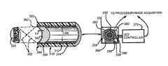
With reference toFIG. 3 , a version of thelight pipe 310 described inFIGS. 1 and 2 is shown. This light pipe includes anouter tube 312 and a nested,inner tube 314. The innermost wall of theinner tube 314 defines, in this example, a circular lumen or channel. This channel is a path through which light can pass from the area ofinterest 320 to a board-mounted or separately placedsensor 330. The lumen has a diameter WL that is equal to or greater than the diameter of the optics of the camera sensor. In this embodiment, note that the sensor is mounted on acircuit board 332 that also includes thering illuminator 334. This ring illuminator consists of an outer ring of LEDs or other appropriatelight sources 336 and aninner ring 338 of LEDs or other appropriate light sources. The number of light sources, size of the rings and their shape are highly variable. Thus, the term “ring” should be taken broadly to describe a variety of regular and irregular curved (ovular, etc.) and/or polygonal (rectangular, square, etc.) perimeter shapes. In general, the ring illuminator's light sources are placed relatively close to the outer perimeter of the sensor and/or its optics and the number of sources is sufficient to fill in the illumination field and supply appropriate light to the subject. In general, any group of light sources or one or more continuous sources (e.g., tubes) arranged to light a perimeter of any size/shape can be broadly considered to be a “ring” light source herein. In one embodiment, the ring can define a circle that is approximately 3-4 inches in outer diameter. Each ring is aligned with respect to one of thelight pipes
As noted, each light pipe is constructed from a light-transmissive material. This material can be acrylic, glass, or any other material capable of acting as a wave guide for visible and near-visible light. The wall thickness of each pipe may vary. In general, thicknesses are between approximately ⅛ inch and ¼ inch. However, larger or smaller thicknesses are expressly contemplated. The overall length of the outer light pipe is also highly variable. As noted above, it is set so that the focus on the desired field of view is attained near, but beyond, the end of thetip 340. In one embodiment, the outer light pipe has a length of approximately 3-4 inches. Theinner light pipe 314 can be approximately the same length as the outer light pipe, but in this embodiment, the inner light pipe is recessed with respect to the outer, as shown, so that light can exit from the inner edge of thetip 340. The tip's light-transmissive region is shown by the dashedline 342. This inner-edge light outlet can be formed by exposing and/or polishing a strip in the otherwise opaque overall surface of the outerlight pipe 312. This light transmissive strip or region can extend (for example) ¼ inch, more or less, as shown by thickness T. The thickness T is variable. Due to internal reflection caused by theangled portion 350 of thetip 340,low angle illumination 352 exits from theopen region 342. Similarly, theopen tip 360 of theinner light pipe 314 facilitates direct,bright field illumination 362 on the area ofinterest 320. The mechanics of the nestedlight pipe 310 are described in further detail below. Reference will first be made toFIG. 4 , which describes, more particularly, a dark field illuminator. Reference will also be made generally to thering illuminator 334 andcontroller 370 ofFIG. 3 .
Note that, while an opaque coating of paint or another acceptable material is used to insulate the dark field light pipe against light leakage, it is contemplated that all or a portion of the light pipe can remain uncovered, particularly where the surface is sufficiently well-polished to cause near-total internal reflection along its length.
As shown inFIG. 4 , a single ring illuminator of LEDs or otherlight sources 410 may be provided on acircuit board 412 along with a CMOS, CCD or other electro-optical sensor 414. Note that the sensor, as described in any of the embodiments herein, may be separate from the light source's circuit board or combined with it. These elements interconnect to a controller and/or image acquisition processor similar to those shown inFIG. 3 . A dark field-illuminatinglight pipe 420 is shown in cross-section. This surrounds theimage sensor 414 and its associatedoptics 422. Atransparent window 424 can be provided in front of theoptics 422 to protect the circuitry. As noted above, thetip 430 of thelight pipe 420 is angled at an angle A (approximately 45 degrees or more) so that light is reflected to pass through an exposed thickness T along the inner perimeter of the light pipe using internal reflection. The light transmits with the desired low-angle (or a high-angle (over 45 degrees) respect to optical axis centerline CL) darkfield illumination patter 440 that, in this embodiment, is within a range DD of 0-1.25 inch. Note that the angle A of the tip (approximately 45 degrees in this example) determines the general angular range of light exiting the tip. There tends to be a spread of angles, in fact, and the prevailing angle of light may vary somewhat from the angle of the tip. The angle A of the tip may be altered to generate the best angle and spread for light based upon the material used for the light pipe and it's wall thickness.
As also shown inFIG. 4 an extended bright field range DB oD-4 inches extends beyond the dark field range. In one embodiment, the bright field is not illuminated or can be illuminated by a variety of other external sources. To this end, in an alternate embodiment, the dark field light source may further include an externalbright field illuminator 450 and/or460. In one example, the bright field illuminator is a ring light source (with or without a light pipe)450 that mayor may not be mounted on the circuit board412 (see board extensions shown in phantom). The radial spacing of the optional, external bright field ring is variable. It may closely abut the dark fieldlight pipe 420, or may be spaced away from this light pipe as shown. According to another alternative, abright field illuminator 460 may be provided at another external location or locations. Note that the term “external” as used herein should be taken broadly to include a location that is inside the lumen of the dark field light pipe, such as, for example at the base of the pipe (adjacent to the circuit board, for example). This illuminator can be provided as the only bright field illuminator, or in addition to thebright field ring 450.
In order to enhance the abilities of the dark field illuminator, the controller (seecontroller 370 inFIG. 3 ) interconnects with a number of segments of the LED ring. Referring again toFIG. 3 , the depictedouter LED ring 336 has four exemplary segments that represent thequadrants controller 370 individually addresses each of the quadrants380-386. In this manner, the quadrants can be separately controlled/modulated. They can be turned on or off, or dimmed and brightened selectively to provide the best dark field illumination pattern for a particular subject. It has been observed that illumination of metallic and similar materials is often more effective when oriented along the grain of the material. With the ability to dim or deactivate illumination across the grain, a significantly improved image is attained.
In one embodiment, the scanning application or another image processor can be used to determine the best lighting based upon the detected image's characteristics. This can entail a rapid cycling of light segments through a variety of preset on/off combinations until the best image quality is attained. This involves a feedback between the sensor, the scanning application and the LED controller. In other words, the sensor signal is processed by the scanning application for each different setting of the LEDs, and when an acceptable and/or optimal image is attained, that particular setting is chosen. Image optimization can be based upon recognition of known fiducials or detection of maximum contrast over a sufficiently wide portion of the viewed area of interest.
In a fixed-camera arrangement, this adjustment process can be carried out once, and the selected setting can be applied to each successive acquired image. Alternatively, in certain handheld scanning applications, where angles and orientations of the appliance relative to the item are likely to change, the adjustments can be made dynamically for each scan. Note that a fixed setting can also be chosen where the scan will always be taken from approximately the same location. Thus, it is contemplated that any of the dark field illuminators, including that shown inFIG. 4 , can include a ring illuminator enabling selectable control, with an associated LED controller. It is also expressly contemplated that the control of LEDs can be implemented in a variety of ways and with a wide range of ring segmentation options. While four segments are shown in the embodiment ofFIG. 3 , it is contemplated, in alternate embodiments, that the ring may be divided into just two halves, or any larger number of segments can be employed. In fact, each LED may be separately controllable/addressable in one embodiment to attain the desired dark field illumination pattern.
As shown generally in the embodiment of inFIG. 3 , the light pipe can include at least two nested (coaxial) light pipes for providing both dark field and bright field illumination in a single unit. The choice of whether dark field or bright field illumination best suits a particular subject can be made by the controller, image processor (automated) or by the operator (manual). According to an automated process, both bright field and dark field illumination can be attempted, and that which attains the best image quality is employed.
With reference now toFIG. 5 , a light pipe having only a bright field illuminator is shown. A circuit board,510, carriesLEDs 512 surrounding asensor 514 with associatedoptics 516 and awindow 518 to protect them. Alight pipe 520 communicates optically with thering illuminator LEDs 512. Thetip 522 of thelight pipe 520 can be rounded or flat and can include a diffusing (frosted, for example) surface texture for enhanced scatter of bright field light. Note that other bright field light pipes described herein can have similar tip constructions and surfaces. The walls (inner and outer) of thelight pipe 522 can be coated with an opaque, non-transmissive material or can remain transmissive. Surrounding the outer circumference of thelight pipe 520 at various points are each of a set of individual directing rods/lenses530 (shown in partial cross-section for clarity of rod-like structure) that each optically communicate with individual or clusters ofLEDs 532. Because the field of view of the sensor is limited, and the subject must remain within the field of view to be properly read, theLEDs 532 project aiming points, typically of a different, noticeable color onto the item of interest. For example the aiming LEDs can project a prominent blue, red or green dot while the overall illumination is a whitish light. Note that the aiming point rods herein are circular in cross section. However, they may be triangular, square or any other shape that adequately denotes an aiming point.
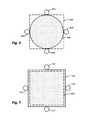
Two exemplary illumination patterns obtained with the bright field illuminator ofFIG. 5 are shown, respectively inFIGS. 6 and 7 . InFIG. 6 , the field of view of the camera sensor, shown as a dashedline 602, is rectangular, while the circular bright field illuminator projects acircular illumination pattern 604. This may be desirable where the subject has a circular outline and the comers of the field of view are not needed, or where the symbol/subject orientation is unknown. The scanning application and/or image acquisition circuitry can be set to reject data within these comers to speed processing. To ensure that the user aligns the illuminator properly with respect to the subject, four aimingdots 610 are provided around the perimeter of theillumination field 604. These aiming dots give instant feedback to the user so that he or she properly aims the illumination and field of view of the appliance onto the subject. Similarly, as shown inFIG. 7 , where a square light pipe is employed, asquare illumination pattern 710 is provided. This falls within the relative field ofview 602. Again, aimingdots 712 are used to ensure proper direction of the appliance by the user. In this embodiment, the dark field illumination range DB1 spans generally between approximately 0 and 12 inches from thetip 522 of the light pipe. Other ranges are contemplated, of course.
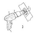
As also described generally above, the light pipe can be used to restrict the native field of view of the sensor.FIG. 9 shows ascanning appliance 902 having a rectangular cross-sectionlight pipe 904. This light pipe can either be a dark field or bright field (or combination) illuminator. In this example, anitem 910 includes a long,narrow subject 912, namely a one-dimensional bar code. The illuminator projects a pattern similar in size and shape to the bar code itself. In this manner, when the user directs the illumination field to theitem 910, he or she is naturally prompted to align the rectangular illumination pattern with the bar code. That is, the user receives immediate feedback as to the location of the reduced field of view, which appears as a bright area that generally conforms to the subject outline. The subject is better delineated by the reduced area, and any information outside this area can be omitted from the acquisition data stream, thus speeding image processing.
With reference toFIG. 10 , the overall field of view of the camera, shown as dashedline 1002, is a large square while the illumination area is a substantiallynarrower rectangle 1004. Again, this rectangle conforms to the shape of a one-dimensional bar code in this example. A variety of other shapes and sizes can be provided for a selective illumination area with respect to the overall field of view. Small circles, ovals, squares and complex geometric patterns are all contemplated. Appropriately shaped light pipes are constructed to conform to these shapes. Likewise, these light pipes can include dark field, bright field or a combination of bright and dark field structures as described above. Similarly, the narrowed-field of view (or “reduced field of view”) illuminator can include aiming dots to further assist alignment on the subject.
Finally, as shown inFIG. 11 , in the example of a bright field illuminator, a ring ofLEDs 1102 is mounted on acircuit board 1104, which also includes asensor 1106. The board is interconnected with a controller or image acquisition device that includes scanning software applications. A bright field illumination pattern extends a distance DB3 from the tip of thelight pipe 1120. In this example the distance DB3 is approximately 12 inches. However other distances are expressly contemplated. The scanning software application is adapted to reject pixels outside of the desired field of view either through knowledge of pixel addresses that fall outside of the desired field or because these pixels are not appropriately illuminated and are therefore rejected (e.g., they are too dark). Anappropriate optics 1110 andwindow 1112 is also provided as well as alight pipe 1120 that is shaped as an elongated rectangle.
The foregoing has been a detailed description of illustrative embodiments of this invention. Various modifications and additions can be made without departing from the spirit and scope thereof. For example, it is expressly contemplated that any of the features described in any of the above embodiments can be combined with other features to produce the desired light pipe arrangement. Likewise, a wide variety of data processing devices, scanning application programs and/or hardware systems can be incorporated to control illumination and acquire images. Finally, the light pipes described herein can be provided with integral illuminators on a circuit board that also includes a sensor and control functions that allow the sensor to communicate with the illuminator. Alternatively, the illuminator, light pipe and camera can all be separate components that are interconnected via one or more controllers, or all connected to a common computer or processor through appropriate interfaces. Various combinations of sensor, optics, illuminator and light pipes are all expressly contemplated. For example, sensors may be provided on the same circuit board as the processor and the light sources, or any/all of these components can be separate. Appropriate interfaces and attachment mechanisms, that should be clear to those of ordinary skill, can be provided to facilitate interaction between the various components described herein. In addition, while the bright field light pipe is described as nested within the dark field light pipe, it is expressly contemplated that these two pipes can be reversed by positioning the bright field illuminator outside the dark field light pipe. Likewise, either light pipe (or light source therefore) may be defined as a broken ring, with non-illuminated segments along their perimeters. Accordingly, this description is meant to be taken only by way of example and not to otherwise limit the scope of the invention.
Claims (10)
1. A handheld scanning device comprising:
a grip section;
a body section;
a first light pipe comprising a light transmissive material terminating in an angled tip;
a second light pipe comprising a light transmissive material terminating in a square tip; and
a first and second ring illuminator that are aligned with the first and second light pipe wherein at least one of the first or second light pipes are removably mounted to the body section.
2. The handheld scanning device ofclaim 1 wherein the first and second light pipes have a cross section with a predetermined shape.
3. The handheld scanning device ofclaim 2 wherein the predetermined shape is one of a circle, a rectangle, or a curved shape.
4. The handheld scanning device ofclaim 1 wherein the first light pipe and the second light pipe are mounted together with a securing ring sized and arranged to secure to a camera assembly.
5. The handheld scanning device ofclaim 4 wherein the mounting ring is constructed and arranged to removably secure the first light pipe and the second light pipe to the camera assembly.
6. The handheld scanning device ofclaim 1 wherein the first light pipe is nested within the second light pipe.
7. The handheld scanning device ofclaim 1 wherein the second light pipe is nested within the first light pipe.
8. The handheld scanner device ofclaim 1 wherein of wherein the first and second ring illuminator has four quadrants that are configured to be modulated separately.
9. The handheld scanner ofclaim 1 wherein the angled tip is configured to generate low angle illumination on an area of interest.
10. The handheld scanner of clam1 wherein the square tip is configured to generate bright field illumination on an area of interest.
Priority Applications (3)
| Application Number | Priority Date | Filing Date | Title |
|---|---|---|---|
| US14/316,906US9329332B2 (en) | 2003-10-24 | 2014-06-27 | Light pipe illumination system and method |
| US14/683,622US9536124B1 (en) | 2003-10-24 | 2015-04-10 | Integrated illumination assembly for symbology reader |
| US15/225,546US20170213060A1 (en) | 2003-10-24 | 2016-08-01 | Integrated illumination assembly for symbology reader |
Applications Claiming Priority (5)
| Application Number | Priority Date | Filing Date | Title |
|---|---|---|---|
| US10/693,626US7823783B2 (en) | 2003-10-24 | 2003-10-24 | Light pipe illumination system and method |
| US12/900,593US8061614B2 (en) | 2003-10-24 | 2010-10-08 | Light pipe illumination system and method |
| US13/294,286US8342405B2 (en) | 2003-10-24 | 2011-11-11 | Light pipe illumination system and method |
| US13/623,336US8770483B2 (en) | 2003-10-24 | 2012-09-20 | Light pipe illumination system and method |
| US14/316,906US9329332B2 (en) | 2003-10-24 | 2014-06-27 | Light pipe illumination system and method |
Related Parent Applications (1)
| Application Number | Title | Priority Date | Filing Date |
|---|---|---|---|
| US13/623,336ContinuationUS8770483B2 (en) | 2003-10-24 | 2012-09-20 | Light pipe illumination system and method |
Related Child Applications (2)
| Application Number | Title | Priority Date | Filing Date |
|---|---|---|---|
| US14/683,622Continuation-In-PartUS9536124B1 (en) | 2003-10-24 | 2015-04-10 | Integrated illumination assembly for symbology reader |
| US14/683,622ContinuationUS9536124B1 (en) | 2003-10-24 | 2015-04-10 | Integrated illumination assembly for symbology reader |
Publications (2)
| Publication Number | Publication Date |
|---|---|
| US20150016139A1 US20150016139A1 (en) | 2015-01-15 |
| US9329332B2true US9329332B2 (en) | 2016-05-03 |
Family
ID=34522441
Family Applications (5)
| Application Number | Title | Priority Date | Filing Date |
|---|---|---|---|
| US10/693,626Expired - Fee RelatedUS7823783B2 (en) | 2003-10-24 | 2003-10-24 | Light pipe illumination system and method |
| US12/900,593Expired - Fee RelatedUS8061614B2 (en) | 2003-10-24 | 2010-10-08 | Light pipe illumination system and method |
| US13/294,286Expired - Fee RelatedUS8342405B2 (en) | 2003-10-24 | 2011-11-11 | Light pipe illumination system and method |
| US13/623,336Expired - Fee RelatedUS8770483B2 (en) | 2003-10-24 | 2012-09-20 | Light pipe illumination system and method |
| US14/316,906Expired - Fee RelatedUS9329332B2 (en) | 2003-10-24 | 2014-06-27 | Light pipe illumination system and method |
Family Applications Before (4)
| Application Number | Title | Priority Date | Filing Date |
|---|---|---|---|
| US10/693,626Expired - Fee RelatedUS7823783B2 (en) | 2003-10-24 | 2003-10-24 | Light pipe illumination system and method |
| US12/900,593Expired - Fee RelatedUS8061614B2 (en) | 2003-10-24 | 2010-10-08 | Light pipe illumination system and method |
| US13/294,286Expired - Fee RelatedUS8342405B2 (en) | 2003-10-24 | 2011-11-11 | Light pipe illumination system and method |
| US13/623,336Expired - Fee RelatedUS8770483B2 (en) | 2003-10-24 | 2012-09-20 | Light pipe illumination system and method |
Country Status (2)
| Country | Link |
|---|---|
| US (5) | US7823783B2 (en) |
| WO (1) | WO2005041556A2 (en) |
Cited By (3)
| Publication number | Priority date | Publication date | Assignee | Title |
|---|---|---|---|---|
| US10893175B2 (en) | 2019-02-27 | 2021-01-12 | Bendix Commercial Vehicle Systems Llc | Shadowless camera housing |
| US11720763B2 (en) | 2020-02-27 | 2023-08-08 | Zebra Technologies Corporation | Optical arrangement in machine vision system with diffusive and direct illumination for DPM indicia |
| US12060991B1 (en) | 2023-11-17 | 2024-08-13 | Brady Worldwide, Inc. | Light pipe with uniform and segmented light outputs for barcode-reading devices |
Families Citing this family (99)
| Publication number | Priority date | Publication date | Assignee | Title |
|---|---|---|---|---|
| US9070031B2 (en) | 2003-10-24 | 2015-06-30 | Cognex Technology And Investment Llc | Integrated illumination assembly for symbology reader |
| US7823789B2 (en) | 2004-12-21 | 2010-11-02 | Cognex Technology And Investment Corporation | Low profile illumination for direct part mark readers |
| US7874487B2 (en)* | 2005-10-24 | 2011-01-25 | Cognex Technology And Investment Corporation | Integrated illumination assembly for symbology reader |
| US7823783B2 (en) | 2003-10-24 | 2010-11-02 | Cognex Technology And Investment Corporation | Light pipe illumination system and method |
| US7604174B2 (en) | 2003-10-24 | 2009-10-20 | Cognex Technology And Investment Corporation | Method and apparatus for providing omnidirectional lighting in a scanning device |
| US9536124B1 (en) | 2003-10-24 | 2017-01-03 | Cognex Corporation | Integrated illumination assembly for symbology reader |
| US7617984B2 (en) | 2004-12-16 | 2009-11-17 | Cognex Technology And Investment Corporation | Hand held symbology reader illumination diffuser |
| US9292724B1 (en) | 2004-12-16 | 2016-03-22 | Cognex Corporation | Hand held symbology reader illumination diffuser with aimer optics |
| US8203616B2 (en)* | 2004-12-30 | 2012-06-19 | Symbol Technologies, Inc. | Imaging scanner |
| DE102005005536A1 (en)* | 2005-02-07 | 2006-08-10 | Sick Ag | code reader |
| US8061610B2 (en)* | 2005-10-24 | 2011-11-22 | Cognex Technology And Investment Corporation | System and method for employing color illumination and color filtration in a symbology reader |
| US7965887B2 (en)* | 2005-12-01 | 2011-06-21 | Cognex Technology And Investment Corp. | Method of pattern location using color image data |
| US7614563B1 (en) | 2005-12-29 | 2009-11-10 | Cognex Technology And Investment Corporation | System and method for providing diffuse illumination in a symbology reader |
| US20070153084A1 (en)* | 2005-12-30 | 2007-07-05 | George Deveau | Semiconductor wafer reader and illumination system |
| JP4708220B2 (en)* | 2006-03-03 | 2011-06-22 | 富士通株式会社 | Illumination device and imaging device using the same |
| JP4804962B2 (en)* | 2006-03-03 | 2011-11-02 | 富士通株式会社 | Imaging device |
| JP4566929B2 (en)* | 2006-03-03 | 2010-10-20 | 富士通株式会社 | Imaging device |
| JP4745084B2 (en)* | 2006-03-03 | 2011-08-10 | 富士通株式会社 | Imaging device |
| US20080074898A1 (en)* | 2006-06-02 | 2008-03-27 | Bookham Technology Plc | Light source assemblies |
| US8016199B2 (en)* | 2006-12-14 | 2011-09-13 | Cognex Corporation | Illumination devices for image acquisition systems |
| AT505464B1 (en)* | 2007-05-14 | 2009-06-15 | Durst Phototech Digital Tech | INK SUPPLY SYSTEM FOR AN INK JET PRINTER |
| JP5002709B2 (en)* | 2007-08-14 | 2012-08-15 | 株式会社オプトエレクトロニクス | Imaging device |
| DE102007043609B4 (en) | 2007-09-13 | 2014-05-28 | Ioss Intelligente Optische Sensoren & Systeme Gmbh | Integrated lighting device for an optical code reader |
| US20090108075A1 (en)* | 2007-10-31 | 2009-04-30 | Igor Vinogradov | Sealed housing with integral window and integral pressure indicator in electro-optical reader |
| US7822300B2 (en)* | 2007-11-20 | 2010-10-26 | Aptina Imaging Corporation | Anti-resonant reflecting optical waveguide for imager light pipe |
| US8585567B2 (en)* | 2007-12-11 | 2013-11-19 | Tokitae Llc | Systems, devices, and methods including paramagnetic oscillation, rotation and translation of hemozoin asymmetric nanoparticles in response to multi-harmonic optical detection of the presence of hemozoin |
| US8385997B2 (en)* | 2007-12-11 | 2013-02-26 | Tokitae Llc | Spectroscopic detection of malaria via the eye |
| EP2227899B1 (en)* | 2007-12-17 | 2015-01-21 | Omnivision Technologies, Inc. | Reflowable camera module with integrated flash |
| US20090218403A1 (en)* | 2008-02-29 | 2009-09-03 | Eugene Joseph | Arrangement for and method of accurately aiming at direct part markings prior to being imaged and electro-optically read |
| US7710570B2 (en)* | 2008-04-18 | 2010-05-04 | Avago Technologies Ecbu Ip (Singapore) Pte. Ltd. | Light pipe for low profile optical navigation systems |
| US20100014288A1 (en)* | 2008-07-15 | 2010-01-21 | Presence From Innovation, Llc | Retro-fit light stick device and secondary light source or other electrical device for use with walk-in type coolers and other product display units |
| JP5069191B2 (en)* | 2008-08-22 | 2012-11-07 | 興和株式会社 | Optical reader |
| US20100148221A1 (en)* | 2008-11-13 | 2010-06-17 | Zena Technologies, Inc. | Vertical photogate (vpg) pixel structure with nanowires |
| US8889455B2 (en)* | 2009-12-08 | 2014-11-18 | Zena Technologies, Inc. | Manufacturing nanowire photo-detector grown on a back-side illuminated image sensor |
| US9343490B2 (en) | 2013-08-09 | 2016-05-17 | Zena Technologies, Inc. | Nanowire structured color filter arrays and fabrication method of the same |
| US8866065B2 (en) | 2010-12-13 | 2014-10-21 | Zena Technologies, Inc. | Nanowire arrays comprising fluorescent nanowires |
| US8735797B2 (en) | 2009-12-08 | 2014-05-27 | Zena Technologies, Inc. | Nanowire photo-detector grown on a back-side illuminated image sensor |
| US8519379B2 (en) | 2009-12-08 | 2013-08-27 | Zena Technologies, Inc. | Nanowire structured photodiode with a surrounding epitaxially grown P or N layer |
| US8835831B2 (en) | 2010-06-22 | 2014-09-16 | Zena Technologies, Inc. | Polarized light detecting device and fabrication methods of the same |
| US9299866B2 (en) | 2010-12-30 | 2016-03-29 | Zena Technologies, Inc. | Nanowire array based solar energy harvesting device |
| US8274039B2 (en) | 2008-11-13 | 2012-09-25 | Zena Technologies, Inc. | Vertical waveguides with various functionality on integrated circuits |
| US8748799B2 (en) | 2010-12-14 | 2014-06-10 | Zena Technologies, Inc. | Full color single pixel including doublet or quadruplet si nanowires for image sensors |
| US8791470B2 (en) | 2009-10-05 | 2014-07-29 | Zena Technologies, Inc. | Nano structured LEDs |
| US9406709B2 (en) | 2010-06-22 | 2016-08-02 | President And Fellows Of Harvard College | Methods for fabricating and using nanowires |
| US9082673B2 (en) | 2009-10-05 | 2015-07-14 | Zena Technologies, Inc. | Passivated upstanding nanostructures and methods of making the same |
| US8890271B2 (en) | 2010-06-30 | 2014-11-18 | Zena Technologies, Inc. | Silicon nitride light pipes for image sensors |
| US8299472B2 (en) | 2009-12-08 | 2012-10-30 | Young-June Yu | Active pixel sensor with nanowire structured photodetectors |
| US9000353B2 (en) | 2010-06-22 | 2015-04-07 | President And Fellows Of Harvard College | Light absorption and filtering properties of vertically oriented semiconductor nano wires |
| US8229255B2 (en)* | 2008-09-04 | 2012-07-24 | Zena Technologies, Inc. | Optical waveguides in image sensors |
| US9478685B2 (en) | 2014-06-23 | 2016-10-25 | Zena Technologies, Inc. | Vertical pillar structured infrared detector and fabrication method for the same |
| US8546742B2 (en) | 2009-06-04 | 2013-10-01 | Zena Technologies, Inc. | Array of nanowires in a single cavity with anti-reflective coating on substrate |
| US8269985B2 (en) | 2009-05-26 | 2012-09-18 | Zena Technologies, Inc. | Determination of optimal diameters for nanowires |
| US9515218B2 (en)* | 2008-09-04 | 2016-12-06 | Zena Technologies, Inc. | Vertical pillar structured photovoltaic devices with mirrors and optical claddings |
| CN102483798B (en)* | 2009-10-30 | 2015-01-28 | 富士通先端科技株式会社 | Illumination Optical System for Camera Devices |
| WO2011100065A2 (en)* | 2010-02-10 | 2011-08-18 | Tokitae Llc | Systems, devices, and methods including a dark-field reflected-illumination apparatus |
| US9044141B2 (en) | 2010-02-10 | 2015-06-02 | Tokitae Llc | Systems, devices, and methods including a dark-field reflected-illumination apparatus |
| US8781184B2 (en)* | 2010-02-10 | 2014-07-15 | Tokitae Llc | Systems, devices, and methods for detection of malaria |
| JP5581157B2 (en)* | 2010-09-17 | 2014-08-27 | 株式会社キーエンス | Illumination setting support device for optical information reader |
| TWI436285B (en)* | 2011-03-16 | 2014-05-01 | Generalplus Technology Inc | Optical identification module device and optical reader having the same |
| US10528772B1 (en) | 2012-02-24 | 2020-01-07 | Socket Mobile, Inc. | Assisted aimer for optimized symbol scanning by a portable computing device having an integral camera |
| US9587804B2 (en)* | 2012-05-07 | 2017-03-07 | Chia Ming Chen | Light control systems and methods |
| CH706642B1 (en)* | 2012-06-22 | 2017-05-31 | Icoflex Sàrl | Optoelectronic instrument for measuring the movement of moving parts of a mechanical watch caliber as well as the measuring method. |
| US9485473B2 (en)* | 2012-09-13 | 2016-11-01 | Alstom Technology Ltd | Method and system for determining quality of tubes |
| US9188839B2 (en)* | 2012-10-04 | 2015-11-17 | Cognex Corporation | Component attachment devices and related systems and methods for machine vision systems |
| CA2889495A1 (en) | 2012-10-30 | 2014-05-08 | California Institute Of Technology | Fourier ptychographic imaging systems, devices, and methods |
| US10652444B2 (en) | 2012-10-30 | 2020-05-12 | California Institute Of Technology | Multiplexed Fourier ptychography imaging systems and methods |
| US9864184B2 (en) | 2012-10-30 | 2018-01-09 | California Institute Of Technology | Embedded pupil function recovery for fourier ptychographic imaging devices |
| WO2014210502A1 (en) | 2013-06-28 | 2014-12-31 | Chia Ming Chen | Controlling device operation according to hand gestures |
| US9717118B2 (en) | 2013-07-16 | 2017-07-25 | Chia Ming Chen | Light control systems and methods |
| EP3028088B1 (en) | 2013-07-31 | 2022-01-19 | California Institute of Technology | Aperture scanning fourier ptychographic imaging |
| CN105765690B (en)* | 2013-08-22 | 2019-01-18 | 加州理工学院 | Variable Illumination Fourier Overlay Correlation Imaging Apparatus, System, and Method |
| US11468557B2 (en) | 2014-03-13 | 2022-10-11 | California Institute Of Technology | Free orientation fourier camera |
| EP3146262A4 (en) | 2014-04-29 | 2018-03-14 | Chia Ming Chen | Light control systems and methods |
| US10162161B2 (en) | 2014-05-13 | 2018-12-25 | California Institute Of Technology | Ptychography imaging systems and methods with convex relaxation |
| WO2016007662A1 (en)* | 2014-07-08 | 2016-01-14 | Padloc Inc. | Imaging and peripheral enhancements for mobile devices |
| CN107111118B (en) | 2014-12-22 | 2019-12-10 | 加州理工学院 | EPI illumination Fourier ptychographic imaging for thick samples |
| CN107209362B (en) | 2015-01-21 | 2020-11-06 | 加州理工学院 | Fourier overlap correlation tomography |
| AU2016211635A1 (en) | 2015-01-26 | 2017-06-29 | California Institute Of Technology | Multi-well fourier ptychographic and fluorescence imaging |
| US11385452B2 (en) | 2015-03-13 | 2022-07-12 | Genea Ip Holdings Pty Limited | Method and apparatus for microscopy |
| AU2016233588A1 (en) | 2015-03-13 | 2017-10-26 | California Institute Of Technology | Correcting for aberrations in incoherent imaging system using fourier ptychographic techniques |
| US9993149B2 (en) | 2015-03-25 | 2018-06-12 | California Institute Of Technology | Fourier ptychographic retinal imaging methods and systems |
| WO2016187591A1 (en) | 2015-05-21 | 2016-11-24 | California Institute Of Technology | Laser-based fourier ptychographic imaging systems and methods |
| CN106932399B (en)* | 2015-12-30 | 2020-02-18 | 上海微电子装备(集团)股份有限公司 | A dark field lighting device and surface defect detection device |
| US20170299851A1 (en)* | 2016-04-14 | 2017-10-19 | Hand Held Products, Inc. | Customizable aimer system for indicia reading terminal |
| US11092795B2 (en) | 2016-06-10 | 2021-08-17 | California Institute Of Technology | Systems and methods for coded-aperture-based correction of aberration obtained from Fourier ptychography |
| US10568507B2 (en) | 2016-06-10 | 2020-02-25 | California Institute Of Technology | Pupil ptychography methods and systems |
| USD832845S1 (en)* | 2016-08-01 | 2018-11-06 | Hand Held Products, Inc. | Optical scanner |
| WO2018209580A1 (en) | 2017-05-17 | 2018-11-22 | Hand Held Products, Inc. | Multi-functional optical illuminators |
| EP3635611B1 (en)* | 2017-06-06 | 2021-04-21 | Sicpa Holding Sa | An illumination device for an optical system of a reader apparatus |
| US10216969B2 (en)* | 2017-07-10 | 2019-02-26 | Hand Held Products, Inc. | Illuminator for directly providing dark field and bright field illumination |
| CN109424871B (en) | 2017-08-18 | 2023-05-05 | 手持产品公司 | Illuminator for bar code scanner |
| WO2019090149A1 (en) | 2017-11-03 | 2019-05-09 | California Institute Of Technology | Parallel digital imaging acquisition and restoration methods and systems |
| US10690303B2 (en) | 2017-12-28 | 2020-06-23 | Bezel Studio | Lighting devices and methods |
| TWI662353B (en)* | 2018-07-13 | 2019-06-11 | 松翰科技股份有限公司 | Optical image sensing module |
| TWI697138B (en)* | 2018-08-24 | 2020-06-21 | 三得電子股份有限公司 | LED projection device and method for controlling deflection light field angle |
| TWI803716B (en)* | 2019-11-27 | 2023-06-01 | 廣達電腦股份有限公司 | Scanning device and method of automatically triggering the same through specific motion trajectory |
| DE102020134734A1 (en) | 2020-12-22 | 2022-06-23 | Ioss Intelligente Optische Sensoren & Systeme Gmbh | Attachment optics, system and method for using attachment optics |
| US12198300B2 (en) | 2021-02-25 | 2025-01-14 | California Institute Of Technology | Computational refocusing-assisted deep learning |
| WO2025183739A1 (en)* | 2024-02-29 | 2025-09-04 | Verifone, Inc. | Systems and methods for card reader overlay detection |
Citations (247)
| Publication number | Priority date | Publication date | Assignee | Title |
|---|---|---|---|---|
| US2357378A (en) | 1941-12-01 | 1944-09-05 | Bausch & Lomb | Microscope illuminator |
| US3726998A (en) | 1971-08-09 | 1973-04-10 | Phonocopy Inc | Light pipe illuminated scan reader |
| US3857626A (en) | 1971-12-10 | 1974-12-31 | Bausch & Lomb | Microscope coaxial illumination apparatus |
| US3961198A (en) | 1975-04-28 | 1976-06-01 | Rockwell International Corporation | Visually alignable sensor wand which excludes unwanted light from a sensor system |
| JPS5362387U (en) | 1976-10-29 | 1978-05-26 | ||
| US4240748A (en) | 1978-06-26 | 1980-12-23 | Caere Corporation | Hand-held optical character recognition wand with visual aligner |
| US4282425A (en) | 1979-07-25 | 1981-08-04 | Norand Corporation | Instant portable bar code reader |
| JPS59163677U (en) | 1983-04-15 | 1984-11-01 | 松下電工株式会社 | Support structure of flush toilet water supply hose |
| US4570057A (en) | 1981-12-28 | 1986-02-11 | Norand Corporation | Instant portable bar code reader |
| US4743773A (en) | 1984-08-23 | 1988-05-10 | Nippon Electric Industry Co., Ltd. | Bar code scanner with diffusion filter and plural linear light source arrays |
| US4766300A (en) | 1984-08-06 | 1988-08-23 | Norand Corporation | Instant portable bar code reader |
| EP0185782B1 (en) | 1984-12-28 | 1989-03-15 | International Business Machines Corporation | Waveguide for an optical near-field microscope |
| US4820911A (en) | 1986-07-11 | 1989-04-11 | Photographic Sciences Corporation | Apparatus for scanning and reading bar codes |
| DE3737792A1 (en) | 1987-11-06 | 1989-05-18 | Hannes Burkhardt | Bar-code reader |
| US4894523A (en) | 1981-12-28 | 1990-01-16 | Norand Corporation | Instant portable bar code reader |
| EP0356680A1 (en) | 1988-08-11 | 1990-03-07 | Siemens Aktiengesellschaft | Optical recording apparatus for an image-processing system |
| US4929053A (en) | 1988-02-01 | 1990-05-29 | U.S. Philips Corporation | Display unit and optical waveguide for use in same |
| JPH02100580U (en) | 1989-01-28 | 1990-08-10 | ||
| US4984523A (en) | 1988-12-07 | 1991-01-15 | Jervis B. Webb Company | Self-propelled trolley and supporting track structure |
| US5019699A (en) | 1988-08-31 | 1991-05-28 | Norand Corporation | Hand-held optical character reader with means for instantaneously reading information from a predetermined area at an optical sensing area |
| WO1991012489A1 (en) | 1990-02-09 | 1991-08-22 | Abos Automation, Bildverarbeitung Optische Systeme Gmbh | Process and device for automatic monitoring of space-shape data in the manufacture of semiconductor components |
| DE3931044C2 (en) | 1989-09-16 | 1992-01-02 | Dirk R. H. 6101 Bickenbach De Dickfeld | |
| JPH04223583A (en) | 1990-12-26 | 1992-08-13 | Smk Corp | barcode reader device |
| US5149948A (en) | 1990-07-16 | 1992-09-22 | Computer Identics | Improved bar code reader system for reading bar codes under high specular reflection conditions with a variety of surface effects |
| WO1992016909A1 (en) | 1991-03-21 | 1992-10-01 | Dansam Holdings Limited | Bar-code reader |
| US5177346A (en) | 1989-12-13 | 1993-01-05 | Computer Identics | Bar code reader system for reading bar code labels with a highly specular and low contrast surface |
| US5202817A (en) | 1989-06-07 | 1993-04-13 | Norand Corporation | Hand-held data capture system with interchangeable modules |
| US5227614A (en) | 1986-08-15 | 1993-07-13 | Norand Corporation | Core computer processor module, and peripheral shell module assembled to form a pocket size data capture unit |
| US5239169A (en) | 1991-05-20 | 1993-08-24 | Microscan Systems Incorporated | Optical signal processor for barcode reader |
| US5258606A (en) | 1981-12-28 | 1993-11-02 | Norand Corporation | Instant portable bar code reader |
| US5291009A (en) | 1992-02-27 | 1994-03-01 | Roustaei Alexander R | Optical scanning head |
| US5309277A (en) | 1992-06-19 | 1994-05-03 | Zygo Corporation | High intensity illuminator |
| JPH06124361A (en) | 1992-10-12 | 1994-05-06 | Nippon Electric Ind Co Ltd | Method for light projection of bar code reader |
| US5313373A (en) | 1992-11-25 | 1994-05-17 | United Parcel Service Of America, Inc. | Apparatus for the uniform illumination of a surface |
| US5319182A (en) | 1992-03-04 | 1994-06-07 | Welch Allyn, Inc. | Integrated solid state light emitting and detecting array and apparatus employing said array |
| US5331176A (en) | 1992-04-10 | 1994-07-19 | Veritec Inc. | Hand held two dimensional symbol reader with a symbol illumination window |
| WO1994019908A1 (en) | 1993-02-16 | 1994-09-01 | Northeast Robotics, Inc. | Continuous diffuse illumination method and apparatus |
| US5349172A (en) | 1992-02-27 | 1994-09-20 | Alex Roustaei | Optical scanning head |
| US5354977A (en) | 1992-02-27 | 1994-10-11 | Alex Roustaei | Optical scanning head |
| US5359185A (en) | 1992-05-11 | 1994-10-25 | Norand Corporation | Chromatic ranging method and apparatus for reading optically readable information over a substantial range of distances |
| US5367439A (en) | 1992-12-24 | 1994-11-22 | Cognex Corporation | System for frontal illumination |
| US5374817A (en) | 1988-05-11 | 1994-12-20 | Symbol Technologies, Inc. | Pre-objective scanner with flexible optical support |
| US5378883A (en) | 1991-07-19 | 1995-01-03 | Omniplanar Inc. | Omnidirectional wide range hand held bar code reader |
| US5393967A (en) | 1993-07-21 | 1995-02-28 | Sensis Corporation | Method and apparatus for non-contact reading of a relief pattern |
| US5406060A (en) | 1993-05-06 | 1995-04-11 | Opticon Inc. | Bar code reader for sensing at an acute angle |
| US5408084A (en) | 1993-02-18 | 1995-04-18 | United Parcel Service Of America, Inc. | Method and apparatus for illumination and imaging of a surface using 2-D LED array |
| US5414251A (en) | 1992-03-12 | 1995-05-09 | Norand Corporation | Reader for decoding two-dimensional optical information |
| US5422472A (en) | 1992-12-04 | 1995-06-06 | Psc, Inc. | Optical symbol (bar code) reading systems having an electro-optic receptor with embedded grating rings |
| US5430285A (en) | 1993-08-20 | 1995-07-04 | Welch Allyn, Inc. | Illumination system for optical reader |
| US5434618A (en) | 1993-06-07 | 1995-07-18 | Fuji Photo Film Co., Ltd. | Electronic still camera operable with a removably mounted storage medium |
| US5449892A (en) | 1991-10-29 | 1995-09-12 | Nippondenso Co., Ltd. | Information reading apparatus |
| JPH07271890A (en) | 1994-04-01 | 1995-10-20 | Asahi Optical Co Ltd | Data symbol reader |
| US5463214A (en) | 1994-03-04 | 1995-10-31 | Welch Allyn, Inc. | Apparatus for optimizing throughput in decoded-output scanners and method of using same |
| US5469294A (en) | 1992-05-01 | 1995-11-21 | Xrl, Inc. | Illumination system for OCR of indicia on a substrate |
| US5481098A (en) | 1993-11-09 | 1996-01-02 | Spectra-Physics Scanning Systems, Inc. | Method and apparatus for reading multiple bar code formats |
| US5484994A (en) | 1993-10-18 | 1996-01-16 | Roustaei; Alexander | Optical scanning head with improved resolution |
| US5500516A (en) | 1994-08-30 | 1996-03-19 | Norand Corporation | Portable oblique optical reader system and method |
| US5504317A (en) | 1994-01-05 | 1996-04-02 | Opticon, Inc. | Optical reader |
| US5504367A (en) | 1994-03-21 | 1996-04-02 | Intermec Corporation | Symbology reader illumination system |
| US5513264A (en) | 1994-04-05 | 1996-04-30 | Metanetics Corporation | Visually interactive encoding and decoding of dataforms |
| US5515452A (en) | 1992-12-31 | 1996-05-07 | Electroglas, Inc. | Optical character recognition illumination method and system |
| US5514858A (en) | 1995-02-10 | 1996-05-07 | Intermec Corporation | Method and apparatus for decoding unresolved complex multi-width bar code symbology profiles |
| JPH08129597A (en) | 1994-09-07 | 1996-05-21 | Alps Electric Co Ltd | Optical reader |
| US5569902A (en) | 1995-01-17 | 1996-10-29 | Welch Allyn, Inc. | Contact two-dimensional bar code reader having pressure actuated switch |
| JPH08287176A (en) | 1995-04-13 | 1996-11-01 | Keyence Corp | Bar code reader |
| US5576527A (en) | 1994-06-20 | 1996-11-19 | Asahi Kogaku Kogyo Kabushiki Kaisha | Optical reader for information pattern representing coded data |
| US5586212A (en) | 1994-07-06 | 1996-12-17 | Hewlett-Packard | Optical wave guide for hand-held scanner |
| US5585616A (en) | 1995-05-05 | 1996-12-17 | Rockwell International Corporation | Camera for capturing and decoding machine-readable matrix symbol images applied to reflective surfaces |
| US5591955A (en) | 1993-05-11 | 1997-01-07 | Laser; Vadim | Portable data file readers |
| US5598007A (en) | 1994-03-21 | 1997-01-28 | Intermec Corporation | Symbology reader with fixed focus spotter beam |
| US5606160A (en) | 1993-03-25 | 1997-02-25 | Asahi Kogaku Kogyo Kabushiki Kaisha | Symbol reading device |
| US5619029A (en) | 1995-04-04 | 1997-04-08 | Rockwell International Corporation | Imaging enhancement for touch cameras |
| US5623137A (en) | 1993-08-20 | 1997-04-22 | Welch Allyn, Inc. | Illumination apparatus for optical readers |
| US5654540A (en) | 1995-08-17 | 1997-08-05 | Stanton; Stuart | High resolution remote position detection using segmented gratings |
| US5654533A (en) | 1992-10-26 | 1997-08-05 | Kabushiki Kaisha Tec | Apparatus and method for reading two-dimensional symbols |
| US5690417A (en) | 1996-05-13 | 1997-11-25 | Optical Gaging Products, Inc. | Surface illuminator with means for adjusting orientation and inclination of incident illumination |
| US5697699A (en) | 1993-09-09 | 1997-12-16 | Asahi Kogaku Kogyo Kabushiki Kaisha | Lighting apparatus |
| US5703348A (en) | 1994-12-26 | 1997-12-30 | Kabushiki Kaisha Tec | Hand-held optical code reader |
| US5715095A (en) | 1994-02-22 | 1998-02-03 | Matsushita Electric Industrial Co., Ltd. | Color separating device and color image reading device incorporating same |
| US5723868A (en) | 1995-05-15 | 1998-03-03 | Welch Allyn, Inc. | Illuminating assembly for use with bar code readers |
| US5734153A (en) | 1985-02-28 | 1998-03-31 | Symbol Technologies, Inc. | Hand-held scanning head with aiming beam |
| DE4123916C2 (en) | 1990-07-19 | 1998-04-09 | Reinhard Malz | Method and device for dynamic detection and classification of surface features and defects of an object |
| US5743633A (en) | 1995-12-27 | 1998-04-28 | Physical Optics Corporation | Bar code illuminator |
| US5750974A (en) | 1995-04-13 | 1998-05-12 | Keyence Corporation | Lighting apparatus having light emitting diodes arranged in a plurality of planes on a printed circuit board |
| JPH10134133A (en) | 1996-11-05 | 1998-05-22 | Olympus Optical Co Ltd | Bar code reader |
| US5756981A (en) | 1992-02-27 | 1998-05-26 | Symbol Technologies, Inc. | Optical scanner for reading and decoding one- and-two-dimensional symbologies at variable depths of field including memory efficient high speed image processing means and high accuracy image analysis means |
| US5773810A (en) | 1996-03-29 | 1998-06-30 | Welch Allyn, Inc. | Method for generating real time degree of focus signal for handheld imaging device |
| US5777314A (en) | 1992-02-27 | 1998-07-07 | Symbol | Optical scanner with fixed focus optics |
| US5783811A (en) | 1995-06-26 | 1998-07-21 | Metanetics Corporation | Portable data collection device with LED targeting and illumination assembly |
| US5786586A (en) | 1995-01-17 | 1998-07-28 | Welch Allyn, Inc. | Hand-held optical reader having a detachable lens-guide assembly |
| US5793033A (en) | 1996-03-29 | 1998-08-11 | Metanetics Corporation | Portable data collection device with viewing assembly |
| US5811784A (en) | 1995-06-26 | 1998-09-22 | Telxon Corporation | Extended working range dataform reader |
| DE69502293T2 (en) | 1994-10-25 | 1998-11-26 | United Parcel Service Of America, Inc., Atlanta, Ga. | METHOD AND DEVICE FOR A PORTABLE CONTACTLESS IMAGE RECORDING DEVICE |
| US5859418A (en) | 1996-01-25 | 1999-01-12 | Symbol Technologies, Inc. | CCD-based bar code scanner with optical funnel |
| US5861910A (en) | 1996-04-02 | 1999-01-19 | Mcgarry; E. John | Image formation apparatus for viewing indicia on a planar specular substrate |
| US5894348A (en) | 1994-06-17 | 1999-04-13 | Kensington Laboratories, Inc. | Scribe mark reader |
| US5903391A (en) | 1996-03-27 | 1999-05-11 | Kimoto Co., Ltd. | Optical film |
| US5907148A (en) | 1994-08-22 | 1999-05-25 | Casio Computer Co., Ltd. | Portable reading apparatus for scan-reading a code using a laser light beam |
| US5920643A (en) | 1997-05-16 | 1999-07-06 | Northeast Robotics Llc | Flexible lighting element circuit and method of manufacturing the same |
| US5923020A (en) | 1995-03-31 | 1999-07-13 | Lintec Corporation | Lighting apparatus |
| US5949763A (en) | 1997-07-17 | 1999-09-07 | Ameritech Corporation | Method and apparatus for providing broadband access conferencing services |
| WO1999049347A1 (en) | 1998-03-20 | 1999-09-30 | Auto Image Id, Inc. | Target illumination device |
| US5969321A (en) | 1986-08-08 | 1999-10-19 | Norand Corporation | Hand-held optically readable information set reader with operation over a range of distances |
| JPH11312898A (en) | 1998-02-27 | 1999-11-09 | Matsushita Electric Ind Co Ltd | Electronic component mounting equipment |
| US5979763A (en) | 1995-10-13 | 1999-11-09 | Metanetics Corporation | Sub-pixel dataform reader with dynamic noise margins |
| US5984494A (en) | 1995-09-08 | 1999-11-16 | Jimmy G. Cook | Light shield for an illumination system |
| US6011586A (en) | 1996-12-04 | 2000-01-04 | Cognex Corporation | Low-profile image formation apparatus |
| US6022124A (en) | 1997-08-19 | 2000-02-08 | Ppt Vision, Inc. | Machine-vision ring-reflector illumination system and method |
| US6034379A (en) | 1996-03-01 | 2000-03-07 | Intermec Ip Corp. | Code reader having replaceable optics assemblies supporting multiple illuminators |
| US6036095A (en) | 1996-05-17 | 2000-03-14 | Asahi Kogaku Kogyo Kabushiki Kaisha | Data symbol reader with observation window |
| US6039255A (en) | 1996-08-28 | 2000-03-21 | Asahi Kogaku Kogyo Kabushiki Kaisha | Data symbol reading apparatus |
| US6039254A (en) | 1993-03-18 | 2000-03-21 | Siemens Aktiengesellschaft | Method for imaging bar codes |
| WO2000016073A1 (en) | 1998-09-11 | 2000-03-23 | Robotic Vision Systems Inc. | Diffuse surface illumination apparatus and methods |
| US6042012A (en) | 1994-12-23 | 2000-03-28 | Spectra-Physics Scanning Systems, Inc. | Method and apparatus for reading images without need for self-generated illumination source |
| US6045047A (en) | 1995-01-17 | 2000-04-04 | Welch Allyn Data Collection, Inc. | Two-dimensional part reader having a focussing guide |
| US6060722A (en) | 1995-05-15 | 2000-05-09 | Havens; William H. | Optical reader having illumination assembly including improved aiming pattern generator |
| US6073852A (en) | 1996-06-06 | 2000-06-13 | Asahi Kogaku Kogyo Kabushiki Kaisha | Data symbol reader with an observation window |
| JP2000231600A (en) | 1998-12-22 | 2000-08-22 | Datalogig Spa | Automatic adjustment method of characteristic variables in optical code reading system |
| US6105869A (en) | 1997-10-31 | 2000-08-22 | Microscan Systems, Incorporated | Symbol reading device including optics for uniformly illuminating symbology |
| US6119939A (en) | 1998-07-08 | 2000-09-19 | Welch Allyn, Inc. | Optical assembly for barcode scanner |
| US6141046A (en) | 1994-10-25 | 2000-10-31 | Roth; Stephen Anthony | Electronic camera having an illuminator with dispersing ring lens |
| US6158661A (en) | 1981-12-28 | 2000-12-12 | Intermec Ip Corp. | Instant portable bar code reader |
| US6164544A (en) | 1998-07-08 | 2000-12-26 | Welch Allyn Data Collection, Inc. | Adjustable illumination system for a barcode scanner |
| WO2001001118A1 (en) | 1999-06-24 | 2001-01-04 | Koninklijke Philips Electronics N.V. | Illumination module |
| JP2001043301A (en) | 1999-05-26 | 2001-02-16 | Denso Corp | Two-dimensional code reader |
| US6210013B1 (en) | 1996-03-10 | 2001-04-03 | Imperial Chemical Industries Plc | Refrigerator comprising edge-lit panel illumination system |
| US6223986B1 (en) | 1997-04-17 | 2001-05-01 | Psc Scanning, Inc. | Aiming aid for optical data reading |
| US6234397B1 (en) | 1998-10-22 | 2001-05-22 | Symbol Technologies, Inc. | Techniques for reading two dimensional code, including maxicode |
| US6247645B1 (en) | 1999-01-25 | 2001-06-19 | International Business Machines Corporation | Optical reader with combined housing and light pipe |
| US6250551B1 (en) | 1998-06-12 | 2001-06-26 | Symbol Technologies, Inc. | Autodiscrimination and line drawing techniques for code readers |
| US6260763B1 (en) | 1996-02-06 | 2001-07-17 | Psc Scanning, Inc. | Integral illumination source/collection lens assembly for data reading system |
| US6267294B1 (en) | 1998-09-11 | 2001-07-31 | Robotic Vision Systems Inc. | Method of operating a charge coupled device in an accelerated mode, and in conjunction with an optical symbology imager |
| WO2001063258A1 (en) | 2000-02-25 | 2001-08-30 | Robotic Vision Systems, Inc. | Optimal symbology illumination-apparatus and method |
| US6283374B1 (en) | 1998-09-11 | 2001-09-04 | Robotic Vision Systems, Inc. | Symbology imaging and reading apparatus and method |
| WO2001065469A1 (en) | 2000-03-02 | 2001-09-07 | Physical Optics Corporation | Scanner utilizing light pipe with diffuser |
| US20010027999A1 (en) | 1998-09-11 | 2001-10-11 | Lee Jason J. | Focus and illumination analysis algorithm for imaging device |
| JP2001307011A (en) | 2000-04-27 | 2001-11-02 | Matsushita Electric Ind Co Ltd | Optical information reader |
| DE10026301A1 (en) | 2000-05-26 | 2001-11-29 | Sick Ag | Image processing method and apparatus |
| US6330974B1 (en) | 1996-03-29 | 2001-12-18 | Intermec Ip Corp. | High resolution laser imager for low contrast symbology |
| US20020000472A1 (en)* | 1999-08-04 | 2002-01-03 | John R. Hattersley | Optical symbol scanner with low angle illumination |
| US6340114B1 (en) | 1998-06-12 | 2002-01-22 | Symbol Technologies, Inc. | Imaging engine and method for code readers |
| US6341878B1 (en) | 1999-08-31 | 2002-01-29 | Cognex Corporation | Method and apparatus for providing uniform diffuse illumination to a surface |
| US6347163B2 (en) | 1994-10-26 | 2002-02-12 | Symbol Technologies, Inc. | System for reading two-dimensional images using ambient and/or projected light |
| US6347874B1 (en) | 2000-02-16 | 2002-02-19 | 3M Innovative Properties Company | Wedge light extractor with risers |
| US20020030094A1 (en)* | 1997-02-10 | 2002-03-14 | Daniel Curry | Arrangement for and method of establishing a logical relationship among peripherals in a wireless local area network |
| US6360948B1 (en) | 1998-11-27 | 2002-03-26 | Denso Corporation | Method of reading two-dimensional code and storage medium thereof |
| US6385352B1 (en) | 1994-10-26 | 2002-05-07 | Symbol Technologies, Inc. | System and method for reading and comparing two-dimensional images |
| US6394349B1 (en) | 1997-10-15 | 2002-05-28 | Denso Corporation | Optical information reader and recording medium |
| US6407810B1 (en) | 2000-03-10 | 2002-06-18 | Robotic Vision Systems, Inc. | Imaging system |
| US20020074403A1 (en) | 1997-02-03 | 2002-06-20 | Mark Krichever | Extended range bar code reader |
| US20020080187A1 (en) | 2000-10-02 | 2002-06-27 | Lawton Scott S. | Enhanced method and system for category selection |
| US20020096566A1 (en) | 2000-11-01 | 2002-07-25 | Welch Allyn, Inc. | Adjustable illumination system for a barcode scanner |
| US20020104887A1 (en)* | 1999-02-22 | 2002-08-08 | Symbol Technologies, Inc. | Hand-held data acquisition device |
| US6435411B1 (en) | 1997-04-21 | 2002-08-20 | Intermec Ip Corp. | Optoelectronic device for acquisition of images, in particular of bar codes |
| US20020125322A1 (en)* | 2001-03-08 | 2002-09-12 | Mccall Melvin D. | Imaging module for optical reader comprising refractive diffuser |
| WO2002075637A1 (en) | 2001-03-19 | 2002-09-26 | Gavitec Ag | Reader with an image recording unit for reading a code and method for reading a code |
| US20020170970A1 (en) | 2001-05-15 | 2002-11-21 | Welch Allyn Data Collection, Inc. | Optical reader having decoding and image capturing functionality |
| US6491223B1 (en) | 1996-09-03 | 2002-12-10 | Hand Held Products, Inc. | Autodiscriminating optical reader |
| US20030001018A1 (en) | 2001-05-02 | 2003-01-02 | Hand Held Products, Inc. | Optical reader comprising good read indicator |
| US6505778B1 (en) | 1998-07-17 | 2003-01-14 | Psc Scanning, Inc. | Optical reader with selectable processing characteristics for reading data in multiple formats |
| US6513714B1 (en) | 1998-09-14 | 2003-02-04 | Psc Scanning, Inc. | Character reconstruction and element level processing in bar code scanning system |
| US20030029917A1 (en) | 1999-10-04 | 2003-02-13 | Hand Held Products, Inc. | Optical reader for imaging module |
| US20030034394A1 (en) | 1999-10-04 | 2003-02-20 | Hand Held Products, Inc. | Optical reader comprising finely adjustable lens assembly |
| JP2003050371A (en) | 2001-08-07 | 2003-02-21 | Sankyo Seiki Mfg Co Ltd | Disk driving motor |
| US20030058631A1 (en) | 2001-09-25 | 2003-03-27 | Kenji Yoneda | Lighting apparatus for insepection |
| US20030062413A1 (en) | 1999-10-04 | 2003-04-03 | Hand Held Products, Inc. | Optical reader comprising multiple color illumination |
| US20030062418A1 (en) | 2001-01-22 | 2003-04-03 | Welch Allyn Data Collection, Inc. | Optical reader having partial frame operating mode |
| US6547146B1 (en) | 2000-05-03 | 2003-04-15 | Ipilot, Inc. | Method, system and apparatus for processing barcode data |
| US20030080189A1 (en)* | 2001-10-26 | 2003-05-01 | Symbol Technologies, Inc. | Bar code reader including linear sensor array and hybrid camera and bar code reader |
| US20030080187A1 (en) | 1998-06-01 | 2003-05-01 | Marco Piva | Apparatus and method for reading an optical code |
| US6575367B1 (en) | 1998-11-05 | 2003-06-10 | Welch Allyn Data Collection, Inc. | Image data binarization methods enabling optical reader to read fine print indicia |
| US6592040B2 (en) | 1998-03-20 | 2003-07-15 | Symbol Technologies, Inc. | Hand-held bar code reader with single printed circuit board |
| US6595422B1 (en) | 1999-06-23 | 2003-07-22 | Assure Systems, Inc. | Bar code reader |
| US6607132B1 (en) | 1998-03-20 | 2003-08-19 | Symbol Technologies, Inc. | Bar code reader with an integrated scanning component module mountable on printed circuit board |
| US6607128B1 (en) | 1998-07-08 | 2003-08-19 | Welch Allyn Data Collection Inc. | Optical assembly for barcode scanner |
| US20030163623A1 (en)* | 2002-02-22 | 2003-08-28 | Yeung Chi Ping | Image capture device |
| US6621065B1 (en) | 1999-11-30 | 2003-09-16 | Mitutoyo Corporation | Imaging probe |
| WO2004000064A1 (en) | 2002-06-25 | 2003-12-31 | Schwan-Stabilo Schwanhäusser Gmbh & Co. Kg | Receptacle for accommodating at least one pencil |
| US6681037B1 (en) | 1999-05-27 | 2004-01-20 | Cognex Corporation | Apparatus for locating features of an object using varied illumination |
| US6689998B1 (en) | 2000-07-05 | 2004-02-10 | Psc Scanning, Inc. | Apparatus for optical distancing autofocus and imaging and method of using the same |
| US20040069855A1 (en) | 2002-10-15 | 2004-04-15 | Mehul Patel | Imaging bar code reader with moving beam simulation |
| JP2004127215A (en) | 2002-09-30 | 2004-04-22 | Aisin Engineering Kk | Code reader |
| WO2004006438A3 (en) | 2002-07-08 | 2004-04-29 | Veritec Inc | Method for reading a symbol having encoded information |
| US6760165B2 (en) | 2002-04-22 | 2004-07-06 | Symbol Technologies, Inc. | System and method for manufacturing an assembly including a housing and a window member therein |
| US20040156539A1 (en)* | 2003-02-10 | 2004-08-12 | Asm Assembly Automation Ltd | Inspecting an array of electronic components |
| US6803088B2 (en) | 2002-10-24 | 2004-10-12 | Eastman Kodak Company | Reflection media for scannable information system |
| US6809847B2 (en) | 1999-04-27 | 2004-10-26 | Psc Scanning, Inc. | Scanner with synchronously switched optics |
| US20040217173A1 (en)* | 2003-05-01 | 2004-11-04 | Lizotte Todd E | Method and apparatus for reading firearm microstamping |
| US20040238637A1 (en)* | 2000-04-18 | 2004-12-02 | Metrologic Instruments, Inc. | Point of sale (POS) based bar code reading and cash register systems with integrated internet-enabled customer-kiosk terminals |
| US6831290B2 (en) | 2002-07-16 | 2004-12-14 | Strube, Inc. | Electro-optic fluid quantity measurement system |
| US20050029439A1 (en)* | 2003-07-21 | 2005-02-10 | Beneficial Imaging Corporation | Method and apparatus for scanning an optical beam using an optical conduit |
| US6854650B2 (en) | 2002-04-10 | 2005-02-15 | Microscan Systems, Inc. | Mirrored surface optical symbol scanner |
| US6855650B1 (en) | 2000-08-25 | 2005-02-15 | American Excelsior Company | Synthetic fiber filled erosion control blanket |
| US6860428B1 (en) | 1998-09-11 | 2005-03-01 | Robotic Vision Systems Inc. | Optical symbologies imager |
| US20050047723A1 (en)* | 2001-05-25 | 2005-03-03 | Li Kenneth K. | Lensed tapered optical waveguide |
| US20050045725A1 (en) | 2003-08-25 | 2005-03-03 | Vladimir Gurevich | Axial chromatic aberration auto-focusing system and method |
| US20050087601A1 (en) | 2003-10-24 | 2005-04-28 | Gerst Carl W.Iii | Light pipe illumination system and method |
| JP2005122355A (en) | 2003-10-15 | 2005-05-12 | Matsushita Electric Ind Co Ltd | Optical information reader |
| WO2005043449A1 (en) | 2003-10-24 | 2005-05-12 | Cognex Technology And Investment Corporation | Method and apparatus for providing omnidirectional lighting in a scanning device |
| US20050117144A1 (en) | 2002-04-10 | 2005-06-02 | Bryan Greenway | Automated protein crystallization imaging |
| US6914679B2 (en) | 2001-12-18 | 2005-07-05 | Cognex Technology And Investment Corporation | Side light apparatus and method |
| US20050180037A1 (en) | 2004-02-18 | 2005-08-18 | Boulder Nonlinear Systems, Inc. | Electronic filter wheel |
| US20050199725A1 (en) | 2004-03-11 | 2005-09-15 | Pierre Craen | Optical adjustment for increased working range and performance in electro-optical readers |
| US20060027657A1 (en) | 2004-08-04 | 2006-02-09 | Laurens Ninnink | Method and apparatus for high resolution decoding of encoded symbols |
| US20060027659A1 (en) | 2003-08-01 | 2006-02-09 | Symbol Technologies, Inc. | Integrated exit window and imaging engine |
| US20060060653A1 (en) | 2004-09-23 | 2006-03-23 | Carl Wittenberg | Scanner system and method for simultaneously acquiring data images from multiple object planes |
| US7021542B2 (en) | 2003-08-01 | 2006-04-04 | Symbol Technologies, Inc. | Imaging and illumination engine for an optical code reader |
| US7025273B2 (en) | 2002-12-18 | 2006-04-11 | Symbol Technologies, Inc. | Miniature auto focus voice coil actuator system |
| US7025271B2 (en) | 2002-12-18 | 2006-04-11 | Symbol Technologies, Inc. | Imaging optical code reader having selectable depths of field |
| US7025572B2 (en) | 2001-07-25 | 2006-04-11 | Denso Corporation | Compressor with integral control unit |
| US7025272B2 (en) | 2002-12-18 | 2006-04-11 | Symbol Technologies, Inc. | System and method for auto focusing an optical code reader |
| US7038853B2 (en) | 1992-03-30 | 2006-05-02 | Symbol Technlogies, Inc. | Athermalized plastic lens |
| US7044377B2 (en) | 2003-08-01 | 2006-05-16 | Symbol Technologies Inc. | Plug-and-play imaging and illumination engine for an optical code reader |
| US20060131419A1 (en) | 2004-12-21 | 2006-06-22 | Laurens Nunnink | Low profile illumination for direct part mark readers |
| US20060133757A1 (en) | 2004-12-16 | 2006-06-22 | Laurens Nunnink | Hand held symbology reader illumination diffuser |
| US7090132B2 (en) | 2002-06-11 | 2006-08-15 | Hand Held Products, Inc. | Long range optical reader |
| US7128266B2 (en) | 2003-11-13 | 2006-10-31 | Metrologic Instruments. Inc. | Hand-supportable digital imaging-based bar code symbol reader supporting narrow-area and wide-area modes of illumination and image capture |
| US7131587B2 (en) | 2004-03-02 | 2006-11-07 | Symbol Technologies, Inc. | System and method for illuminating and reading optical codes imprinted or displayed on reflective surfaces |
| US20060266840A1 (en) | 2005-05-31 | 2006-11-30 | Symbol Technologies, Inc. | Feedback mechanism for scanner devices |
| US7159764B1 (en) | 2003-05-30 | 2007-01-09 | Intermec Ip Corp. | Versatile window system for information gathering systems |
| JP2007028088A (en) | 2005-07-14 | 2007-02-01 | Konica Minolta Holdings Inc | Imaging apparatus and image processing method |
| US7180052B1 (en) | 2005-09-13 | 2007-02-20 | Symbol Technologies, Inc. | Non-heavy metal optical bandpass filter in electro-optical readers |
| US7187825B2 (en) | 2003-12-17 | 2007-03-06 | Symbol Technologies, Inc. | System and method for extending viewing angle of light emitted from light pipe |
| US7204420B2 (en) | 2004-08-31 | 2007-04-17 | Symbol Technologies, Inc. | Scanner and method for eliminating specular reflection |
| US7204418B2 (en) | 2004-12-08 | 2007-04-17 | Symbol Technologies, Inc. | Pulsed illumination in imaging reader |
| US20070090193A1 (en) | 2005-10-24 | 2007-04-26 | Laurens Nunnink | Integrated illumination assembly for symbology reader |
| US20070091332A1 (en) | 2005-10-24 | 2007-04-26 | Laurens Nunnink | System and method for employing color illumination and color filtration in a symbology reader |
| US7224540B2 (en) | 2005-01-31 | 2007-05-29 | Datalogic Scanning, Inc. | Extended depth of field imaging system using chromatic aberration |
| US20070152064A1 (en) | 2005-12-30 | 2007-07-05 | Laurens Nunnink | Diffuse light ring for reading encoded symbols |
| US7253384B2 (en) | 2005-03-23 | 2007-08-07 | Microscan Systems Incorporated | Focusing system using light source and image sensor |
| US20070206183A1 (en) | 1999-07-08 | 2007-09-06 | Ppt Vision, Inc. | Method and apparatus for auto-adjusting illumination |
| US7270274B2 (en) | 1999-10-04 | 2007-09-18 | Hand Held Products, Inc. | Imaging module comprising support post for optical reader |
| US7296749B2 (en) | 2004-01-23 | 2007-11-20 | Intermec Ip Corp. | Autofocus barcode scanner and the like employing micro-fluidic lens |
| US7299310B2 (en) | 2003-11-14 | 2007-11-20 | Sick Ag | Connection module for the connection of a sensor to a fieldbus |
| US7306155B2 (en) | 1998-07-08 | 2007-12-11 | Hand Held Products, Inc. | Image sensor assembly for optical reader |
| US7314173B2 (en) | 1998-09-11 | 2008-01-01 | Lv Partners, L.P. | Optical reader with ultraviolet wavelength capability |
| US7360705B2 (en) | 2005-07-14 | 2008-04-22 | Intermec Ip Corp. | Apparatus and method for reading machine-readable symbols |
| US20080170380A1 (en) | 2006-09-29 | 2008-07-17 | Pastore Timothy M | Systems and/or devices for camera-based inspections |
| US7451917B2 (en) | 2002-01-11 | 2008-11-18 | Hand Held Products, Inc. | Transaction terminal comprising imaging module |
| US7490774B2 (en) | 2003-11-13 | 2009-02-17 | Metrologic Instruments, Inc. | Hand-supportable imaging based bar code symbol reader employing automatic light exposure measurement and illumination control subsystem integrated therein |
| US7520434B2 (en) | 2004-06-25 | 2009-04-21 | Intermec Ip Corp. | Reader for reading machine-readable symbols, for example bar code symbols |
| US7568628B2 (en) | 2005-03-11 | 2009-08-04 | Hand Held Products, Inc. | Bar code reading device with global electronic shutter control |
| US7793017B2 (en) | 2006-06-30 | 2010-09-07 | Sick Ag | Connection module for sensors |
| US7861037B2 (en) | 2007-06-27 | 2010-12-28 | Sandisk Corporation | Methods of auto starting with portable mass storage device |
| USRE42337E1 (en) | 1997-02-20 | 2011-05-10 | Eastman Kodak Company | Network configuration file for automatically transmitting images from an electronic still camera |
| US7967632B2 (en) | 2009-02-26 | 2011-06-28 | Fujitsu Component Limited | Card connector |
| US8069289B2 (en) | 2008-07-31 | 2011-11-29 | Ametek, Inc. | Modbus register data formatting |
Family Cites Families (2)
| Publication number | Priority date | Publication date | Assignee | Title |
|---|---|---|---|---|
| JP3193837B2 (en) | 1994-10-18 | 2001-07-30 | 株式会社日立製作所 | Heating resistance type flow measurement device |
| JP3301580B2 (en) | 1996-06-07 | 2002-07-15 | 矢崎総業株式会社 | Standby connector |
- 2003
- 2003-10-24USUS10/693,626patent/US7823783B2/ennot_activeExpired - Fee Related
- 2004
- 2004-10-18WOPCT/US2004/034389patent/WO2005041556A2/enactiveApplication Filing
- 2010
- 2010-10-08USUS12/900,593patent/US8061614B2/ennot_activeExpired - Fee Related
- 2011
- 2011-11-11USUS13/294,286patent/US8342405B2/ennot_activeExpired - Fee Related
- 2012
- 2012-09-20USUS13/623,336patent/US8770483B2/ennot_activeExpired - Fee Related
- 2014
- 2014-06-27USUS14/316,906patent/US9329332B2/ennot_activeExpired - Fee Related
Patent Citations (299)
| Publication number | Priority date | Publication date | Assignee | Title |
|---|---|---|---|---|
| US2357378A (en) | 1941-12-01 | 1944-09-05 | Bausch & Lomb | Microscope illuminator |
| US3726998A (en) | 1971-08-09 | 1973-04-10 | Phonocopy Inc | Light pipe illuminated scan reader |
| US3857626A (en) | 1971-12-10 | 1974-12-31 | Bausch & Lomb | Microscope coaxial illumination apparatus |
| US3961198A (en) | 1975-04-28 | 1976-06-01 | Rockwell International Corporation | Visually alignable sensor wand which excludes unwanted light from a sensor system |
| JPS5362387U (en) | 1976-10-29 | 1978-05-26 | ||
| US4240748A (en) | 1978-06-26 | 1980-12-23 | Caere Corporation | Hand-held optical character recognition wand with visual aligner |
| US4282425A (en) | 1979-07-25 | 1981-08-04 | Norand Corporation | Instant portable bar code reader |
| US4570057A (en) | 1981-12-28 | 1986-02-11 | Norand Corporation | Instant portable bar code reader |
| US6158661A (en) | 1981-12-28 | 2000-12-12 | Intermec Ip Corp. | Instant portable bar code reader |
| US5258606A (en) | 1981-12-28 | 1993-11-02 | Norand Corporation | Instant portable bar code reader |
| US4894523A (en) | 1981-12-28 | 1990-01-16 | Norand Corporation | Instant portable bar code reader |
| JPS59163677U (en) | 1983-04-15 | 1984-11-01 | 松下電工株式会社 | Support structure of flush toilet water supply hose |
| US4766300A (en) | 1984-08-06 | 1988-08-23 | Norand Corporation | Instant portable bar code reader |
| US4743773A (en) | 1984-08-23 | 1988-05-10 | Nippon Electric Industry Co., Ltd. | Bar code scanner with diffusion filter and plural linear light source arrays |
| EP0185782B1 (en) | 1984-12-28 | 1989-03-15 | International Business Machines Corporation | Waveguide for an optical near-field microscope |
| US5734153A (en) | 1985-02-28 | 1998-03-31 | Symbol Technologies, Inc. | Hand-held scanning head with aiming beam |
| US4820911A (en) | 1986-07-11 | 1989-04-11 | Photographic Sciences Corporation | Apparatus for scanning and reading bar codes |
| US5969321A (en) | 1986-08-08 | 1999-10-19 | Norand Corporation | Hand-held optically readable information set reader with operation over a range of distances |
| US5227614A (en) | 1986-08-15 | 1993-07-13 | Norand Corporation | Core computer processor module, and peripheral shell module assembled to form a pocket size data capture unit |
| DE3737792A1 (en) | 1987-11-06 | 1989-05-18 | Hannes Burkhardt | Bar-code reader |
| US4929053A (en) | 1988-02-01 | 1990-05-29 | U.S. Philips Corporation | Display unit and optical waveguide for use in same |
| US5374817A (en) | 1988-05-11 | 1994-12-20 | Symbol Technologies, Inc. | Pre-objective scanner with flexible optical support |
| US4969037A (en) | 1988-08-11 | 1990-11-06 | Siemens Aktiengesellschaft | Arrangement for illuminating and detecting parts in an image processing system |
| EP0356680A1 (en) | 1988-08-11 | 1990-03-07 | Siemens Aktiengesellschaft | Optical recording apparatus for an image-processing system |
| US5019699A (en) | 1988-08-31 | 1991-05-28 | Norand Corporation | Hand-held optical character reader with means for instantaneously reading information from a predetermined area at an optical sensing area |
| US4984523A (en) | 1988-12-07 | 1991-01-15 | Jervis B. Webb Company | Self-propelled trolley and supporting track structure |
| JPH02100580U (en) | 1989-01-28 | 1990-08-10 | ||
| US5202817A (en) | 1989-06-07 | 1993-04-13 | Norand Corporation | Hand-held data capture system with interchangeable modules |
| DE3931044C2 (en) | 1989-09-16 | 1992-01-02 | Dirk R. H. 6101 Bickenbach De Dickfeld | |
| US5177346A (en) | 1989-12-13 | 1993-01-05 | Computer Identics | Bar code reader system for reading bar code labels with a highly specular and low contrast surface |
| WO1991012489A1 (en) | 1990-02-09 | 1991-08-22 | Abos Automation, Bildverarbeitung Optische Systeme Gmbh | Process and device for automatic monitoring of space-shape data in the manufacture of semiconductor components |
| DE4003983C1 (en) | 1990-02-09 | 1991-08-29 | Abos Automation, Bildverarbeitung, Optische Systeme Gmbh, 8057 Eching, De | Automated monitoring of space=shape data for mfg. semiconductors - compares image signals for defined illumination angle range with master signals, to determine defects |
| US5149948A (en) | 1990-07-16 | 1992-09-22 | Computer Identics | Improved bar code reader system for reading bar codes under high specular reflection conditions with a variety of surface effects |
| DE4123916C2 (en) | 1990-07-19 | 1998-04-09 | Reinhard Malz | Method and device for dynamic detection and classification of surface features and defects of an object |
| JPH04223583A (en) | 1990-12-26 | 1992-08-13 | Smk Corp | barcode reader device |
| WO1992016909A1 (en) | 1991-03-21 | 1992-10-01 | Dansam Holdings Limited | Bar-code reader |
| US5239169A (en) | 1991-05-20 | 1993-08-24 | Microscan Systems Incorporated | Optical signal processor for barcode reader |
| US5378883A (en) | 1991-07-19 | 1995-01-03 | Omniplanar Inc. | Omnidirectional wide range hand held bar code reader |
| DE69228209T2 (en) | 1991-07-19 | 1999-05-27 | Omniplanar, Inc., Princeton, N.J. | Handheld device for reading bar codes |
| US5449892A (en) | 1991-10-29 | 1995-09-12 | Nippondenso Co., Ltd. | Information reading apparatus |
| US5349172A (en) | 1992-02-27 | 1994-09-20 | Alex Roustaei | Optical scanning head |
| US5354977A (en) | 1992-02-27 | 1994-10-11 | Alex Roustaei | Optical scanning head |
| US5291009A (en) | 1992-02-27 | 1994-03-01 | Roustaei Alexander R | Optical scanning head |
| US5532467A (en) | 1992-02-27 | 1996-07-02 | Roustaei; Alex | Optical scanning head |
| US5777314A (en) | 1992-02-27 | 1998-07-07 | Symbol | Optical scanner with fixed focus optics |
| US5756981A (en) | 1992-02-27 | 1998-05-26 | Symbol Technologies, Inc. | Optical scanner for reading and decoding one- and-two-dimensional symbologies at variable depths of field including memory efficient high speed image processing means and high accuracy image analysis means |
| US5319182A (en) | 1992-03-04 | 1994-06-07 | Welch Allyn, Inc. | Integrated solid state light emitting and detecting array and apparatus employing said array |
| US5414251A (en) | 1992-03-12 | 1995-05-09 | Norand Corporation | Reader for decoding two-dimensional optical information |
| US7038853B2 (en) | 1992-03-30 | 2006-05-02 | Symbol Technlogies, Inc. | Athermalized plastic lens |
| US5331176A (en) | 1992-04-10 | 1994-07-19 | Veritec Inc. | Hand held two dimensional symbol reader with a symbol illumination window |
| US5469294A (en) | 1992-05-01 | 1995-11-21 | Xrl, Inc. | Illumination system for OCR of indicia on a substrate |
| US5359185A (en) | 1992-05-11 | 1994-10-25 | Norand Corporation | Chromatic ranging method and apparatus for reading optically readable information over a substantial range of distances |
| US5309277A (en) | 1992-06-19 | 1994-05-03 | Zygo Corporation | High intensity illuminator |
| JPH06124361A (en) | 1992-10-12 | 1994-05-06 | Nippon Electric Ind Co Ltd | Method for light projection of bar code reader |
| US5654533A (en) | 1992-10-26 | 1997-08-05 | Kabushiki Kaisha Tec | Apparatus and method for reading two-dimensional symbols |
| US5313373A (en) | 1992-11-25 | 1994-05-17 | United Parcel Service Of America, Inc. | Apparatus for the uniform illumination of a surface |
| US5422472A (en) | 1992-12-04 | 1995-06-06 | Psc, Inc. | Optical symbol (bar code) reading systems having an electro-optic receptor with embedded grating rings |
| US5367439A (en) | 1992-12-24 | 1994-11-22 | Cognex Corporation | System for frontal illumination |
| US5515452A (en) | 1992-12-31 | 1996-05-07 | Electroglas, Inc. | Optical character recognition illumination method and system |
| US5461417A (en) | 1993-02-16 | 1995-10-24 | Northeast Robotics, Inc. | Continuous diffuse illumination method and apparatus |
| WO1994019908A1 (en) | 1993-02-16 | 1994-09-01 | Northeast Robotics, Inc. | Continuous diffuse illumination method and apparatus |
| JPH08510053A (en) | 1993-02-16 | 1996-10-22 | ノースイースト ロボティックス,インコーポレイテッド | Method and apparatus for continuous diffuse illumination |
| US5408084A (en) | 1993-02-18 | 1995-04-18 | United Parcel Service Of America, Inc. | Method and apparatus for illumination and imaging of a surface using 2-D LED array |
| US6039254A (en) | 1993-03-18 | 2000-03-21 | Siemens Aktiengesellschaft | Method for imaging bar codes |
| US5606160A (en) | 1993-03-25 | 1997-02-25 | Asahi Kogaku Kogyo Kabushiki Kaisha | Symbol reading device |
| US5406060A (en) | 1993-05-06 | 1995-04-11 | Opticon Inc. | Bar code reader for sensing at an acute angle |
| US5992751A (en) | 1993-05-11 | 1999-11-30 | Norand Corporation | Portable data file readers |
| US5591955A (en) | 1993-05-11 | 1997-01-07 | Laser; Vadim | Portable data file readers |
| US5434618A (en) | 1993-06-07 | 1995-07-18 | Fuji Photo Film Co., Ltd. | Electronic still camera operable with a removably mounted storage medium |
| US5393967A (en) | 1993-07-21 | 1995-02-28 | Sensis Corporation | Method and apparatus for non-contact reading of a relief pattern |
| US5430285A (en) | 1993-08-20 | 1995-07-04 | Welch Allyn, Inc. | Illumination system for optical reader |
| US5623137A (en) | 1993-08-20 | 1997-04-22 | Welch Allyn, Inc. | Illumination apparatus for optical readers |
| US6033090A (en) | 1993-09-09 | 2000-03-07 | Asahi Kogaku Kogyo Kabushiki Kaisha | Lighting apparatus |
| US5697699A (en) | 1993-09-09 | 1997-12-16 | Asahi Kogaku Kogyo Kabushiki Kaisha | Lighting apparatus |
| US5484994A (en) | 1993-10-18 | 1996-01-16 | Roustaei; Alexander | Optical scanning head with improved resolution |
| US5481098A (en) | 1993-11-09 | 1996-01-02 | Spectra-Physics Scanning Systems, Inc. | Method and apparatus for reading multiple bar code formats |
| US5504317A (en) | 1994-01-05 | 1996-04-02 | Opticon, Inc. | Optical reader |
| US5715095A (en) | 1994-02-22 | 1998-02-03 | Matsushita Electric Industrial Co., Ltd. | Color separating device and color image reading device incorporating same |
| US5463214A (en) | 1994-03-04 | 1995-10-31 | Welch Allyn, Inc. | Apparatus for optimizing throughput in decoded-output scanners and method of using same |
| US5684290A (en) | 1994-03-21 | 1997-11-04 | Intermec Corporation | Symbology reader illumination system |
| US5886338A (en) | 1994-03-21 | 1999-03-23 | Intermec Ip Corporation | Symbology reader illumination system |
| US5598007A (en) | 1994-03-21 | 1997-01-28 | Intermec Corporation | Symbology reader with fixed focus spotter beam |
| US5504367A (en) | 1994-03-21 | 1996-04-02 | Intermec Corporation | Symbology reader illumination system |
| JPH07271890A (en) | 1994-04-01 | 1995-10-20 | Asahi Optical Co Ltd | Data symbol reader |
| US5659167A (en) | 1994-04-05 | 1997-08-19 | Metanetics Corporation | Visually interactive decoding of dataforms |
| US5513264A (en) | 1994-04-05 | 1996-04-30 | Metanetics Corporation | Visually interactive encoding and decoding of dataforms |
| US5894348A (en) | 1994-06-17 | 1999-04-13 | Kensington Laboratories, Inc. | Scribe mark reader |
| US5576527A (en) | 1994-06-20 | 1996-11-19 | Asahi Kogaku Kogyo Kabushiki Kaisha | Optical reader for information pattern representing coded data |
| US5586212A (en) | 1994-07-06 | 1996-12-17 | Hewlett-Packard | Optical wave guide for hand-held scanner |
| US5907148A (en) | 1994-08-22 | 1999-05-25 | Casio Computer Co., Ltd. | Portable reading apparatus for scan-reading a code using a laser light beam |
| US5500516A (en) | 1994-08-30 | 1996-03-19 | Norand Corporation | Portable oblique optical reader system and method |
| JPH08129597A (en) | 1994-09-07 | 1996-05-21 | Alps Electric Co Ltd | Optical reader |
| US6141046A (en) | 1994-10-25 | 2000-10-31 | Roth; Stephen Anthony | Electronic camera having an illuminator with dispersing ring lens |
| DE69502293T2 (en) | 1994-10-25 | 1998-11-26 | United Parcel Service Of America, Inc., Atlanta, Ga. | METHOD AND DEVICE FOR A PORTABLE CONTACTLESS IMAGE RECORDING DEVICE |
| US6729546B2 (en) | 1994-10-26 | 2004-05-04 | Symbol Technologies, Inc. | System for reading two-dimensional images using ambient and/or projected light |
| US6347163B2 (en) | 1994-10-26 | 2002-02-12 | Symbol Technologies, Inc. | System for reading two-dimensional images using ambient and/or projected light |
| US6385352B1 (en) | 1994-10-26 | 2002-05-07 | Symbol Technologies, Inc. | System and method for reading and comparing two-dimensional images |
| US6042012A (en) | 1994-12-23 | 2000-03-28 | Spectra-Physics Scanning Systems, Inc. | Method and apparatus for reading images without need for self-generated illumination source |
| US5703348A (en) | 1994-12-26 | 1997-12-30 | Kabushiki Kaisha Tec | Hand-held optical code reader |
| US5569902A (en) | 1995-01-17 | 1996-10-29 | Welch Allyn, Inc. | Contact two-dimensional bar code reader having pressure actuated switch |
| US6045047A (en) | 1995-01-17 | 2000-04-04 | Welch Allyn Data Collection, Inc. | Two-dimensional part reader having a focussing guide |
| US5786586A (en) | 1995-01-17 | 1998-07-28 | Welch Allyn, Inc. | Hand-held optical reader having a detachable lens-guide assembly |
| US5514858A (en) | 1995-02-10 | 1996-05-07 | Intermec Corporation | Method and apparatus for decoding unresolved complex multi-width bar code symbology profiles |
| US5923020A (en) | 1995-03-31 | 1999-07-13 | Lintec Corporation | Lighting apparatus |
| US5619029A (en) | 1995-04-04 | 1997-04-08 | Rockwell International Corporation | Imaging enhancement for touch cameras |
| JPH08287176A (en) | 1995-04-13 | 1996-11-01 | Keyence Corp | Bar code reader |
| US5750974A (en) | 1995-04-13 | 1998-05-12 | Keyence Corporation | Lighting apparatus having light emitting diodes arranged in a plurality of planes on a printed circuit board |
| US5585616A (en) | 1995-05-05 | 1996-12-17 | Rockwell International Corporation | Camera for capturing and decoding machine-readable matrix symbol images applied to reflective surfaces |
| US5780834A (en) | 1995-05-15 | 1998-07-14 | Welch Allyn, Inc. | Imaging and illumination optics assembly |
| US5723868A (en) | 1995-05-15 | 1998-03-03 | Welch Allyn, Inc. | Illuminating assembly for use with bar code readers |
| US6060722A (en) | 1995-05-15 | 2000-05-09 | Havens; William H. | Optical reader having illumination assembly including improved aiming pattern generator |
| US5811784A (en) | 1995-06-26 | 1998-09-22 | Telxon Corporation | Extended working range dataform reader |
| US5783811A (en) | 1995-06-26 | 1998-07-21 | Metanetics Corporation | Portable data collection device with LED targeting and illumination assembly |
| US5654540A (en) | 1995-08-17 | 1997-08-05 | Stanton; Stuart | High resolution remote position detection using segmented gratings |
| US5984494A (en) | 1995-09-08 | 1999-11-16 | Jimmy G. Cook | Light shield for an illumination system |
| US5979763A (en) | 1995-10-13 | 1999-11-09 | Metanetics Corporation | Sub-pixel dataform reader with dynamic noise margins |
| US5743633A (en) | 1995-12-27 | 1998-04-28 | Physical Optics Corporation | Bar code illuminator |
| US5859418A (en) | 1996-01-25 | 1999-01-12 | Symbol Technologies, Inc. | CCD-based bar code scanner with optical funnel |
| US6065678A (en) | 1996-01-25 | 2000-05-23 | Symbol Technologies, Inc. | Bar code scanner having a focusing system |
| US6260763B1 (en) | 1996-02-06 | 2001-07-17 | Psc Scanning, Inc. | Integral illumination source/collection lens assembly for data reading system |
| US6249008B1 (en) | 1996-03-01 | 2001-06-19 | Intermec Ip Corp. | Code reader having replaceable optics assemblies supporting multiple illuminators |
| US6034379A (en) | 1996-03-01 | 2000-03-07 | Intermec Ip Corp. | Code reader having replaceable optics assemblies supporting multiple illuminators |
| US6210013B1 (en) | 1996-03-10 | 2001-04-03 | Imperial Chemical Industries Plc | Refrigerator comprising edge-lit panel illumination system |
| US5903391A (en) | 1996-03-27 | 1999-05-11 | Kimoto Co., Ltd. | Optical film |
| US6330974B1 (en) | 1996-03-29 | 2001-12-18 | Intermec Ip Corp. | High resolution laser imager for low contrast symbology |
| US5773810A (en) | 1996-03-29 | 1998-06-30 | Welch Allyn, Inc. | Method for generating real time degree of focus signal for handheld imaging device |
| US5834754A (en) | 1996-03-29 | 1998-11-10 | Metanetics Corporation | Portable data collection device with viewing assembly |
| US5949057A (en) | 1996-03-29 | 1999-09-07 | Telxon Corporation | Portable data collection device with crosshair targeting illumination assembly |
| US5793033A (en) | 1996-03-29 | 1998-08-11 | Metanetics Corporation | Portable data collection device with viewing assembly |
| US5861910A (en) | 1996-04-02 | 1999-01-19 | Mcgarry; E. John | Image formation apparatus for viewing indicia on a planar specular substrate |
| US5690417A (en) | 1996-05-13 | 1997-11-25 | Optical Gaging Products, Inc. | Surface illuminator with means for adjusting orientation and inclination of incident illumination |
| US6036095A (en) | 1996-05-17 | 2000-03-14 | Asahi Kogaku Kogyo Kabushiki Kaisha | Data symbol reader with observation window |
| US6073852A (en) | 1996-06-06 | 2000-06-13 | Asahi Kogaku Kogyo Kabushiki Kaisha | Data symbol reader with an observation window |
| US6039255A (en) | 1996-08-28 | 2000-03-21 | Asahi Kogaku Kogyo Kabushiki Kaisha | Data symbol reading apparatus |
| US6491223B1 (en) | 1996-09-03 | 2002-12-10 | Hand Held Products, Inc. | Autodiscriminating optical reader |
| JPH10134133A (en) | 1996-11-05 | 1998-05-22 | Olympus Optical Co Ltd | Bar code reader |
| US6011586A (en) | 1996-12-04 | 2000-01-04 | Cognex Corporation | Low-profile image formation apparatus |
| US20020074403A1 (en) | 1997-02-03 | 2002-06-20 | Mark Krichever | Extended range bar code reader |
| US20020030094A1 (en)* | 1997-02-10 | 2002-03-14 | Daniel Curry | Arrangement for and method of establishing a logical relationship among peripherals in a wireless local area network |
| USRE42337E1 (en) | 1997-02-20 | 2011-05-10 | Eastman Kodak Company | Network configuration file for automatically transmitting images from an electronic still camera |
| US6223986B1 (en) | 1997-04-17 | 2001-05-01 | Psc Scanning, Inc. | Aiming aid for optical data reading |
| US6435411B1 (en) | 1997-04-21 | 2002-08-20 | Intermec Ip Corp. | Optoelectronic device for acquisition of images, in particular of bar codes |
| US5920643A (en) | 1997-05-16 | 1999-07-06 | Northeast Robotics Llc | Flexible lighting element circuit and method of manufacturing the same |
| US5949763A (en) | 1997-07-17 | 1999-09-07 | Ameritech Corporation | Method and apparatus for providing broadband access conferencing services |
| US6022124A (en) | 1997-08-19 | 2000-02-08 | Ppt Vision, Inc. | Machine-vision ring-reflector illumination system and method |
| US6394349B1 (en) | 1997-10-15 | 2002-05-28 | Denso Corporation | Optical information reader and recording medium |
| US6105869A (en) | 1997-10-31 | 2000-08-22 | Microscan Systems, Incorporated | Symbol reading device including optics for uniformly illuminating symbology |
| US6542238B1 (en) | 1998-02-27 | 2003-04-01 | Matsushita Electric Industrial Co., Ltd. | Electronic component mounting apparatus |
| JPH11312898A (en) | 1998-02-27 | 1999-11-09 | Matsushita Electric Ind Co Ltd | Electronic component mounting equipment |
| US6592040B2 (en) | 1998-03-20 | 2003-07-15 | Symbol Technologies, Inc. | Hand-held bar code reader with single printed circuit board |
| US6607132B1 (en) | 1998-03-20 | 2003-08-19 | Symbol Technologies, Inc. | Bar code reader with an integrated scanning component module mountable on printed circuit board |
| WO1999049347A1 (en) | 1998-03-20 | 1999-09-30 | Auto Image Id, Inc. | Target illumination device |
| US20030080187A1 (en) | 1998-06-01 | 2003-05-01 | Marco Piva | Apparatus and method for reading an optical code |
| US6340114B1 (en) | 1998-06-12 | 2002-01-22 | Symbol Technologies, Inc. | Imaging engine and method for code readers |
| US6250551B1 (en) | 1998-06-12 | 2001-06-26 | Symbol Technologies, Inc. | Autodiscrimination and line drawing techniques for code readers |
| US6405925B2 (en) | 1998-06-12 | 2002-06-18 | Symbol Technologies, Inc. | Autodiscrimination and line drawing techniques for code readers |
| US6164544A (en) | 1998-07-08 | 2000-12-26 | Welch Allyn Data Collection, Inc. | Adjustable illumination system for a barcode scanner |
| US6119939A (en) | 1998-07-08 | 2000-09-19 | Welch Allyn, Inc. | Optical assembly for barcode scanner |
| US7306155B2 (en) | 1998-07-08 | 2007-12-11 | Hand Held Products, Inc. | Image sensor assembly for optical reader |
| US6607128B1 (en) | 1998-07-08 | 2003-08-19 | Welch Allyn Data Collection Inc. | Optical assembly for barcode scanner |
| US6371374B1 (en) | 1998-07-08 | 2002-04-16 | Welch Allyn Data Collection, Inc. | Adjustable illumination system for a barcode scanner |
| US6505778B1 (en) | 1998-07-17 | 2003-01-14 | Psc Scanning, Inc. | Optical reader with selectable processing characteristics for reading data in multiple formats |
| US6283374B1 (en) | 1998-09-11 | 2001-09-04 | Robotic Vision Systems, Inc. | Symbology imaging and reading apparatus and method |
| JP2002525644A (en) | 1998-09-11 | 2002-08-13 | ロボティック ビジョン システムズ インコーポレイテッド | Diffuse surface illumination device and method |
| US6598797B2 (en) | 1998-09-11 | 2003-07-29 | Jason J. Lee | Focus and illumination analysis algorithm for imaging device |
| US6860428B1 (en) | 1998-09-11 | 2005-03-01 | Robotic Vision Systems Inc. | Optical symbologies imager |
| US20010027999A1 (en) | 1998-09-11 | 2001-10-11 | Lee Jason J. | Focus and illumination analysis algorithm for imaging device |
| US6661521B1 (en) | 1998-09-11 | 2003-12-09 | Robotic Vision Systems, Inc. | Diffuse surface illumination apparatus and methods |
| US6267294B1 (en) | 1998-09-11 | 2001-07-31 | Robotic Vision Systems Inc. | Method of operating a charge coupled device in an accelerated mode, and in conjunction with an optical symbology imager |
| WO2000016073A1 (en) | 1998-09-11 | 2000-03-23 | Robotic Vision Systems Inc. | Diffuse surface illumination apparatus and methods |
| US7314173B2 (en) | 1998-09-11 | 2008-01-01 | Lv Partners, L.P. | Optical reader with ultraviolet wavelength capability |
| US6429934B1 (en) | 1998-09-11 | 2002-08-06 | Robotic Vision Systems, Inc. | Optimal symbology illumination-apparatus and method |
| US6513714B1 (en) | 1998-09-14 | 2003-02-04 | Psc Scanning, Inc. | Character reconstruction and element level processing in bar code scanning system |
| US6234397B1 (en) | 1998-10-22 | 2001-05-22 | Symbol Technologies, Inc. | Techniques for reading two dimensional code, including maxicode |
| US6575367B1 (en) | 1998-11-05 | 2003-06-10 | Welch Allyn Data Collection, Inc. | Image data binarization methods enabling optical reader to read fine print indicia |
| US6360948B1 (en) | 1998-11-27 | 2002-03-26 | Denso Corporation | Method of reading two-dimensional code and storage medium thereof |
| JP2000231600A (en) | 1998-12-22 | 2000-08-22 | Datalogig Spa | Automatic adjustment method of characteristic variables in optical code reading system |
| US6247645B1 (en) | 1999-01-25 | 2001-06-19 | International Business Machines Corporation | Optical reader with combined housing and light pipe |
| US20020104887A1 (en)* | 1999-02-22 | 2002-08-08 | Symbol Technologies, Inc. | Hand-held data acquisition device |
| US6809847B2 (en) | 1999-04-27 | 2004-10-26 | Psc Scanning, Inc. | Scanner with synchronously switched optics |
| JP2001043301A (en) | 1999-05-26 | 2001-02-16 | Denso Corp | Two-dimensional code reader |
| US6681037B1 (en) | 1999-05-27 | 2004-01-20 | Cognex Corporation | Apparatus for locating features of an object using varied illumination |
| US6595422B1 (en) | 1999-06-23 | 2003-07-22 | Assure Systems, Inc. | Bar code reader |
| US6385507B1 (en) | 1999-06-24 | 2002-05-07 | U.S. Philips Corporation | Illumination module |
| WO2001001118A1 (en) | 1999-06-24 | 2001-01-04 | Koninklijke Philips Electronics N.V. | Illumination module |
| JP2003503701A (en) | 1999-06-24 | 2003-01-28 | コーニンクレッカ フィリップス エレクトロニクス エヌ ヴィ | Lighting module |
| US20070206183A1 (en) | 1999-07-08 | 2007-09-06 | Ppt Vision, Inc. | Method and apparatus for auto-adjusting illumination |
| US6352204B2 (en) | 1999-08-04 | 2002-03-05 | Industrial Data Entry Automation Systems Incorporated | Optical symbol scanner with low angle illumination |
| US20020000472A1 (en)* | 1999-08-04 | 2002-01-03 | John R. Hattersley | Optical symbol scanner with low angle illumination |
| US6341878B1 (en) | 1999-08-31 | 2002-01-29 | Cognex Corporation | Method and apparatus for providing uniform diffuse illumination to a surface |
| US20030062413A1 (en) | 1999-10-04 | 2003-04-03 | Hand Held Products, Inc. | Optical reader comprising multiple color illumination |
| US7270274B2 (en) | 1999-10-04 | 2007-09-18 | Hand Held Products, Inc. | Imaging module comprising support post for optical reader |
| US20030034394A1 (en) | 1999-10-04 | 2003-02-20 | Hand Held Products, Inc. | Optical reader comprising finely adjustable lens assembly |
| US20030029917A1 (en) | 1999-10-04 | 2003-02-13 | Hand Held Products, Inc. | Optical reader for imaging module |
| US6832725B2 (en) | 1999-10-04 | 2004-12-21 | Hand Held Products, Inc. | Optical reader comprising multiple color illumination |
| US6621065B1 (en) | 1999-11-30 | 2003-09-16 | Mitutoyo Corporation | Imaging probe |
| US6347874B1 (en) | 2000-02-16 | 2002-02-19 | 3M Innovative Properties Company | Wedge light extractor with risers |
| WO2001063258A1 (en) | 2000-02-25 | 2001-08-30 | Robotic Vision Systems, Inc. | Optimal symbology illumination-apparatus and method |
| WO2001065469A1 (en) | 2000-03-02 | 2001-09-07 | Physical Optics Corporation | Scanner utilizing light pipe with diffuser |
| CN1426570A (en) | 2000-03-02 | 2003-06-25 | 物理光学公司 | Scanner utilizing light pipe with diffuser |
| US6407810B1 (en) | 2000-03-10 | 2002-06-18 | Robotic Vision Systems, Inc. | Imaging system |
| US20040238637A1 (en)* | 2000-04-18 | 2004-12-02 | Metrologic Instruments, Inc. | Point of sale (POS) based bar code reading and cash register systems with integrated internet-enabled customer-kiosk terminals |
| JP2001307011A (en) | 2000-04-27 | 2001-11-02 | Matsushita Electric Ind Co Ltd | Optical information reader |
| US6581838B1 (en) | 2000-05-03 | 2003-06-24 | Ipilot, Inc. | Optical scanner head for processing barcode data and method of manufacture |
| US6547146B1 (en) | 2000-05-03 | 2003-04-15 | Ipilot, Inc. | Method, system and apparatus for processing barcode data |
| EP1158460B1 (en) | 2000-05-26 | 2004-10-06 | Sick AG | Image processing system and method |
| DE10026301A1 (en) | 2000-05-26 | 2001-11-29 | Sick Ag | Image processing method and apparatus |
| US6689998B1 (en) | 2000-07-05 | 2004-02-10 | Psc Scanning, Inc. | Apparatus for optical distancing autofocus and imaging and method of using the same |
| US6855650B1 (en) | 2000-08-25 | 2005-02-15 | American Excelsior Company | Synthetic fiber filled erosion control blanket |
| US20020080187A1 (en) | 2000-10-02 | 2002-06-27 | Lawton Scott S. | Enhanced method and system for category selection |
| US20020096566A1 (en) | 2000-11-01 | 2002-07-25 | Welch Allyn, Inc. | Adjustable illumination system for a barcode scanner |
| US6659350B2 (en) | 2000-11-01 | 2003-12-09 | Hand Held Products | Adjustable illumination system for a barcode scanner |
| US20030062418A1 (en) | 2001-01-22 | 2003-04-03 | Welch Allyn Data Collection, Inc. | Optical reader having partial frame operating mode |
| US6601768B2 (en) | 2001-03-08 | 2003-08-05 | Welch Allyn Data Collection, Inc. | Imaging module for optical reader comprising refractive diffuser |
| US20020125322A1 (en)* | 2001-03-08 | 2002-09-12 | Mccall Melvin D. | Imaging module for optical reader comprising refractive diffuser |
| WO2002075637A1 (en) | 2001-03-19 | 2002-09-26 | Gavitec Ag | Reader with an image recording unit for reading a code and method for reading a code |
| US20030001018A1 (en) | 2001-05-02 | 2003-01-02 | Hand Held Products, Inc. | Optical reader comprising good read indicator |
| US20020170970A1 (en) | 2001-05-15 | 2002-11-21 | Welch Allyn Data Collection, Inc. | Optical reader having decoding and image capturing functionality |
| US20050047723A1 (en)* | 2001-05-25 | 2005-03-03 | Li Kenneth K. | Lensed tapered optical waveguide |
| US7025572B2 (en) | 2001-07-25 | 2006-04-11 | Denso Corporation | Compressor with integral control unit |
| JP2003050371A (en) | 2001-08-07 | 2003-02-21 | Sankyo Seiki Mfg Co Ltd | Disk driving motor |
| US20030058631A1 (en) | 2001-09-25 | 2003-03-27 | Kenji Yoneda | Lighting apparatus for insepection |
| US20030080189A1 (en)* | 2001-10-26 | 2003-05-01 | Symbol Technologies, Inc. | Bar code reader including linear sensor array and hybrid camera and bar code reader |
| US6914679B2 (en) | 2001-12-18 | 2005-07-05 | Cognex Technology And Investment Corporation | Side light apparatus and method |
| US7451917B2 (en) | 2002-01-11 | 2008-11-18 | Hand Held Products, Inc. | Transaction terminal comprising imaging module |
| US20030163623A1 (en)* | 2002-02-22 | 2003-08-28 | Yeung Chi Ping | Image capture device |
| US6854650B2 (en) | 2002-04-10 | 2005-02-15 | Microscan Systems, Inc. | Mirrored surface optical symbol scanner |
| US20050117144A1 (en) | 2002-04-10 | 2005-06-02 | Bryan Greenway | Automated protein crystallization imaging |
| US6760165B2 (en) | 2002-04-22 | 2004-07-06 | Symbol Technologies, Inc. | System and method for manufacturing an assembly including a housing and a window member therein |
| US7090132B2 (en) | 2002-06-11 | 2006-08-15 | Hand Held Products, Inc. | Long range optical reader |
| WO2004000064A1 (en) | 2002-06-25 | 2003-12-31 | Schwan-Stabilo Schwanhäusser Gmbh & Co. Kg | Receptacle for accommodating at least one pencil |
| WO2004006438A3 (en) | 2002-07-08 | 2004-04-29 | Veritec Inc | Method for reading a symbol having encoded information |
| US6831290B2 (en) | 2002-07-16 | 2004-12-14 | Strube, Inc. | Electro-optic fluid quantity measurement system |
| JP2004127215A (en) | 2002-09-30 | 2004-04-22 | Aisin Engineering Kk | Code reader |
| US20040069855A1 (en) | 2002-10-15 | 2004-04-15 | Mehul Patel | Imaging bar code reader with moving beam simulation |
| US6803088B2 (en) | 2002-10-24 | 2004-10-12 | Eastman Kodak Company | Reflection media for scannable information system |
| US7025273B2 (en) | 2002-12-18 | 2006-04-11 | Symbol Technologies, Inc. | Miniature auto focus voice coil actuator system |
| US7025271B2 (en) | 2002-12-18 | 2006-04-11 | Symbol Technologies, Inc. | Imaging optical code reader having selectable depths of field |
| US7025272B2 (en) | 2002-12-18 | 2006-04-11 | Symbol Technologies, Inc. | System and method for auto focusing an optical code reader |
| US20040156539A1 (en)* | 2003-02-10 | 2004-08-12 | Asm Assembly Automation Ltd | Inspecting an array of electronic components |
| US20040217173A1 (en)* | 2003-05-01 | 2004-11-04 | Lizotte Todd E | Method and apparatus for reading firearm microstamping |
| US7159764B1 (en) | 2003-05-30 | 2007-01-09 | Intermec Ip Corp. | Versatile window system for information gathering systems |
| US20050029439A1 (en)* | 2003-07-21 | 2005-02-10 | Beneficial Imaging Corporation | Method and apparatus for scanning an optical beam using an optical conduit |
| US20060027659A1 (en) | 2003-08-01 | 2006-02-09 | Symbol Technologies, Inc. | Integrated exit window and imaging engine |
| US7021542B2 (en) | 2003-08-01 | 2006-04-04 | Symbol Technologies, Inc. | Imaging and illumination engine for an optical code reader |
| US7044377B2 (en) | 2003-08-01 | 2006-05-16 | Symbol Technologies Inc. | Plug-and-play imaging and illumination engine for an optical code reader |
| US20050045725A1 (en) | 2003-08-25 | 2005-03-03 | Vladimir Gurevich | Axial chromatic aberration auto-focusing system and method |
| JP2005122355A (en) | 2003-10-15 | 2005-05-12 | Matsushita Electric Ind Co Ltd | Optical information reader |
| US7604174B2 (en) | 2003-10-24 | 2009-10-20 | Cognex Technology And Investment Corporation | Method and apparatus for providing omnidirectional lighting in a scanning device |
| US8061613B2 (en) | 2003-10-24 | 2011-11-22 | Cognex Technology And Investment Corporation | Method and apparatus for providing omnidirectional lighting in a scanning device |
| US20060032921A1 (en) | 2003-10-24 | 2006-02-16 | Gerst Carl W Iii | Method and apparatus for providing omnidirectional lighting in a scanning device |
| EP1687752B1 (en) | 2003-10-24 | 2008-02-20 | Cognex Technology and Investment Corporation | Method and apparatus for providing omnidirectional lighting in a scanning device |
| US8061614B2 (en) | 2003-10-24 | 2011-11-22 | Cognex Technology And Investment Corporation | Light pipe illumination system and method |
| US20050087601A1 (en) | 2003-10-24 | 2005-04-28 | Gerst Carl W.Iii | Light pipe illumination system and method |
| WO2005043449A1 (en) | 2003-10-24 | 2005-05-12 | Cognex Technology And Investment Corporation | Method and apparatus for providing omnidirectional lighting in a scanning device |
| US7823783B2 (en) | 2003-10-24 | 2010-11-02 | Cognex Technology And Investment Corporation | Light pipe illumination system and method |
| US7490774B2 (en) | 2003-11-13 | 2009-02-17 | Metrologic Instruments, Inc. | Hand-supportable imaging based bar code symbol reader employing automatic light exposure measurement and illumination control subsystem integrated therein |
| US7240844B2 (en) | 2003-11-13 | 2007-07-10 | Metrologic Instruments, Inc. | Hand-suportable imaging-based bar code symbol reader employing an automatic light exposure measurement and illumination control subsystem for measuring illumination exposure on CMOS image sensing array and controlling LED illumination array driver circuitry |
| US7278575B2 (en) | 2003-11-13 | 2007-10-09 | Metrologic Instruments, Inc. | Hand-supportable image-based bar code symbol reader employing helically-sweeping feature-extraction analysis on a captured digital image of an object referenced from the center thereof |
| US7281661B2 (en) | 2003-11-13 | 2007-10-16 | Metrologic Instruments, Inc. | Hand-supportable digital imaging-based bar code symbol reading system employing a method of intelligently illuminating an object so as to generate a digital image thereof which is substantially free of noise caused by specular-type reflection |
| US7267282B2 (en) | 2003-11-13 | 2007-09-11 | Metrologic Instruments, Inc. | Hand-supportable imaging-based bar code symbol reader capable of exposing an automatically detected object to a field of narrow-band LED-based illumination only when substantially all rows of pixels in a CMOS image sensing array are in a state of integration |
| US7128266B2 (en) | 2003-11-13 | 2006-10-31 | Metrologic Instruments. Inc. | Hand-supportable digital imaging-based bar code symbol reader supporting narrow-area and wide-area modes of illumination and image capture |
| US7225989B2 (en) | 2003-11-13 | 2007-06-05 | Metrologic Instruments, Inc. | Method of performing auto-discrimination of 1D/2D bar code symbologies in a semi-automatic hand-supportable imaging-based bar code symbol reader having narrow-area and wide-area image capture modes of operation |
| US7299310B2 (en) | 2003-11-14 | 2007-11-20 | Sick Ag | Connection module for the connection of a sensor to a fieldbus |
| US7187825B2 (en) | 2003-12-17 | 2007-03-06 | Symbol Technologies, Inc. | System and method for extending viewing angle of light emitted from light pipe |
| US7296749B2 (en) | 2004-01-23 | 2007-11-20 | Intermec Ip Corp. | Autofocus barcode scanner and the like employing micro-fluidic lens |
| US20050180037A1 (en) | 2004-02-18 | 2005-08-18 | Boulder Nonlinear Systems, Inc. | Electronic filter wheel |
| US7131587B2 (en) | 2004-03-02 | 2006-11-07 | Symbol Technologies, Inc. | System and method for illuminating and reading optical codes imprinted or displayed on reflective surfaces |
| US7163149B2 (en) | 2004-03-02 | 2007-01-16 | Symbol Technologies, Inc. | System and method for illuminating and reading optical codes imprinted or displayed on reflective surfaces |
| US20050199725A1 (en) | 2004-03-11 | 2005-09-15 | Pierre Craen | Optical adjustment for increased working range and performance in electro-optical readers |
| US7520434B2 (en) | 2004-06-25 | 2009-04-21 | Intermec Ip Corp. | Reader for reading machine-readable symbols, for example bar code symbols |
| US20060027657A1 (en) | 2004-08-04 | 2006-02-09 | Laurens Ninnink | Method and apparatus for high resolution decoding of encoded symbols |
| US7204420B2 (en) | 2004-08-31 | 2007-04-17 | Symbol Technologies, Inc. | Scanner and method for eliminating specular reflection |
| US20060060653A1 (en) | 2004-09-23 | 2006-03-23 | Carl Wittenberg | Scanner system and method for simultaneously acquiring data images from multiple object planes |
| US7204418B2 (en) | 2004-12-08 | 2007-04-17 | Symbol Technologies, Inc. | Pulsed illumination in imaging reader |
| JP2008524709A (en) | 2004-12-16 | 2008-07-10 | コグネックス・テクノロジー・アンド・インベストメント・コーポレーション | Handheld symbol reader lighting diffuser |
| US8286878B2 (en) | 2004-12-16 | 2012-10-16 | Cognex Technology And Investment Corporation | Hand held symbology reader illumination diffuser |
| US20060133757A1 (en) | 2004-12-16 | 2006-06-22 | Laurens Nunnink | Hand held symbology reader illumination diffuser |
| US7617984B2 (en) | 2004-12-16 | 2009-11-17 | Cognex Technology And Investment Corporation | Hand held symbology reader illumination diffuser |
| US20060131419A1 (en) | 2004-12-21 | 2006-06-22 | Laurens Nunnink | Low profile illumination for direct part mark readers |
| US7823789B2 (en) | 2004-12-21 | 2010-11-02 | Cognex Technology And Investment Corporation | Low profile illumination for direct part mark readers |
| US8672227B2 (en) | 2004-12-21 | 2014-03-18 | Cognex Technology And Investment Corporation | Low profile illumination for direct part mark readers |
| US7224540B2 (en) | 2005-01-31 | 2007-05-29 | Datalogic Scanning, Inc. | Extended depth of field imaging system using chromatic aberration |
| US7568628B2 (en) | 2005-03-11 | 2009-08-04 | Hand Held Products, Inc. | Bar code reading device with global electronic shutter control |
| US7253384B2 (en) | 2005-03-23 | 2007-08-07 | Microscan Systems Incorporated | Focusing system using light source and image sensor |
| US7331524B2 (en) | 2005-05-31 | 2008-02-19 | Symbol Technologies, Inc. | Feedback mechanism for scanner devices |
| US20060266840A1 (en) | 2005-05-31 | 2006-11-30 | Symbol Technologies, Inc. | Feedback mechanism for scanner devices |
| US7360705B2 (en) | 2005-07-14 | 2008-04-22 | Intermec Ip Corp. | Apparatus and method for reading machine-readable symbols |
| JP2007028088A (en) | 2005-07-14 | 2007-02-01 | Konica Minolta Holdings Inc | Imaging apparatus and image processing method |
| US7180052B1 (en) | 2005-09-13 | 2007-02-20 | Symbol Technologies, Inc. | Non-heavy metal optical bandpass filter in electro-optical readers |
| US7874487B2 (en) | 2005-10-24 | 2011-01-25 | Cognex Technology And Investment Corporation | Integrated illumination assembly for symbology reader |
| US20070090193A1 (en) | 2005-10-24 | 2007-04-26 | Laurens Nunnink | Integrated illumination assembly for symbology reader |
| US20070091332A1 (en) | 2005-10-24 | 2007-04-26 | Laurens Nunnink | System and method for employing color illumination and color filtration in a symbology reader |
| US20070152064A1 (en) | 2005-12-30 | 2007-07-05 | Laurens Nunnink | Diffuse light ring for reading encoded symbols |
| US7793017B2 (en) | 2006-06-30 | 2010-09-07 | Sick Ag | Connection module for sensors |
| US20080170380A1 (en) | 2006-09-29 | 2008-07-17 | Pastore Timothy M | Systems and/or devices for camera-based inspections |
| US7861037B2 (en) | 2007-06-27 | 2010-12-28 | Sandisk Corporation | Methods of auto starting with portable mass storage device |
| US8069289B2 (en) | 2008-07-31 | 2011-11-29 | Ametek, Inc. | Modbus register data formatting |
| US7967632B2 (en) | 2009-02-26 | 2011-06-28 | Fujitsu Component Limited | Card connector |
Non-Patent Citations (11)
| Title |
|---|
| "Vision-Supplies.com", Siemens LytePipe 1.5'' x 30, (1999). |
| "Vision-Supplies.com", Siemens LytePipe 1.5″ x 30, (1999). |
| CCS Inc., "LFX-series Lights", http://www.ccs-inc.co.jp/cgi-bin/hp.cgi?menu=102-115-01e, (2006). |
| Cognex Corporation, "50mm Ring Light Image Formation System", For the In-Sight 5000 series ID Readers, (2006). |
| Cognex Corporation, "AcuReader/OCR", Accurate, Fast Wafer Indentification, (1995-1996). |
| Cognex Corporation, "DataMan 6500 Series", Quick Reference (2004). |
| Cognex Corporation, "DataMan 6500 Series", Quick Reference Guide, (Aug. 10, 2004). |
| Cognex Corporation, "DataMan 7500 Series Handheld Models", Cognex Machine Vision System and Machine Vision Sensors, (2009). |
| Cognex Corporation, "DataMan Handheld ID Readers", (2005). |
| Cognex Corporation, "Diffuse Ring Light Installation Instructions", InSight, (2006). |
| Indata Systems, "4410LDS-Hand Held Etched 2D Image Reader", 27 Fennell Street, Skaneateles, NY 13152, Internet: www.indatasys.com, (Jan.1, 2005), two pages. |
Cited By (3)
| Publication number | Priority date | Publication date | Assignee | Title |
|---|---|---|---|---|
| US10893175B2 (en) | 2019-02-27 | 2021-01-12 | Bendix Commercial Vehicle Systems Llc | Shadowless camera housing |
| US11720763B2 (en) | 2020-02-27 | 2023-08-08 | Zebra Technologies Corporation | Optical arrangement in machine vision system with diffusive and direct illumination for DPM indicia |
| US12060991B1 (en) | 2023-11-17 | 2024-08-13 | Brady Worldwide, Inc. | Light pipe with uniform and segmented light outputs for barcode-reading devices |
Also Published As
| Publication number | Publication date |
|---|---|
| US20120118967A1 (en) | 2012-05-17 |
| US20110024504A1 (en) | 2011-02-03 |
| WO2005041556A2 (en) | 2005-05-06 |
| US20130194819A1 (en) | 2013-08-01 |
| WO2005041556A3 (en) | 2005-06-30 |
| US20150016139A1 (en) | 2015-01-15 |
| US8061614B2 (en) | 2011-11-22 |
| US8342405B2 (en) | 2013-01-01 |
| US20050087601A1 (en) | 2005-04-28 |
| US7823783B2 (en) | 2010-11-02 |
| US8770483B2 (en) | 2014-07-08 |
Similar Documents
| Publication | Publication Date | Title |
|---|---|---|
| US9329332B2 (en) | Light pipe illumination system and method | |
| US9298960B2 (en) | Method and apparatus for providing omnidirectional lighting in a scanning device | |
| JP5615952B2 (en) | Handheld symbol reader lighting diffuser | |
| US9070031B2 (en) | Integrated illumination assembly for symbology reader | |
| US8061610B2 (en) | System and method for employing color illumination and color filtration in a symbology reader | |
| US9405951B2 (en) | Integrated illumination assembly for symbology reader | |
| US20070131770A1 (en) | Selectable focus direct part mark reader | |
| US9536124B1 (en) | Integrated illumination assembly for symbology reader | |
| US9292724B1 (en) | Hand held symbology reader illumination diffuser with aimer optics |
Legal Events
| Date | Code | Title | Description |
|---|---|---|---|
| STCF | Information on status: patent grant | Free format text:PATENTED CASE | |
| FEPP | Fee payment procedure | Free format text:MAINTENANCE FEE REMINDER MAILED (ORIGINAL EVENT CODE: REM.); ENTITY STATUS OF PATENT OWNER: LARGE ENTITY | |
| LAPS | Lapse for failure to pay maintenance fees | Free format text:PATENT EXPIRED FOR FAILURE TO PAY MAINTENANCE FEES (ORIGINAL EVENT CODE: EXP.); ENTITY STATUS OF PATENT OWNER: LARGE ENTITY | |
| STCH | Information on status: patent discontinuation | Free format text:PATENT EXPIRED DUE TO NONPAYMENT OF MAINTENANCE FEES UNDER 37 CFR 1.362 | |
| FP | Lapsed due to failure to pay maintenance fee | Effective date:20200503 |