US9329076B2 - Patient support systems and methods of use - Google Patents
Patient support systems and methods of useDownload PDFInfo
- Publication number
- US9329076B2 US9329076B2US13/828,186US201313828186AUS9329076B2US 9329076 B2US9329076 B2US 9329076B2US 201313828186 AUS201313828186 AUS 201313828186AUS 9329076 B2US9329076 B2US 9329076B2
- Authority
- US
- United States
- Prior art keywords
- section
- head
- bladder
- seat
- support
- Prior art date
- Legal status (The legal status is an assumption and is not a legal conclusion. Google has not performed a legal analysis and makes no representation as to the accuracy of the status listed.)
- Active, expires
Links
- 238000000034methodMethods0.000titledescription2
- 230000004044responseEffects0.000claimsabstractdescription9
- 239000006260foamSubstances0.000claimsdescription35
- 230000003467diminishing effectEffects0.000claimsdescription7
- UQMRAFJOBWOFNS-UHFFFAOYSA-Nbutyl 2-(2,4-dichlorophenoxy)acetateChemical compoundCCCCOC(=O)COC1=CC=C(Cl)C=C1ClUQMRAFJOBWOFNS-UHFFFAOYSA-N0.000description9
- 210000000629knee jointAnatomy0.000description6
- 230000004888barrier functionEffects0.000description5
- 230000015572biosynthetic processEffects0.000description5
- 210000003127kneeAnatomy0.000description5
- 238000004891communicationMethods0.000description4
- 230000007423decreaseEffects0.000description4
- 230000003247decreasing effectEffects0.000description4
- 238000002560therapeutic procedureMethods0.000description4
- 238000009527percussionMethods0.000description3
- 230000008859changeEffects0.000description2
- 239000013013elastic materialSubstances0.000description2
- 230000000284resting effectEffects0.000description2
- 239000007787solidSubstances0.000description2
- 210000000689upper legAnatomy0.000description2
- XLYOFNOQVPJJNP-UHFFFAOYSA-NwaterSubstancesOXLYOFNOQVPJJNP-UHFFFAOYSA-N0.000description2
- 206010011985Decubitus ulcerDiseases0.000description1
- 208000004210Pressure UlcerDiseases0.000description1
- 230000003213activating effectEffects0.000description1
- 230000004913activationEffects0.000description1
- 238000005452bendingMethods0.000description1
- 230000008901benefitEffects0.000description1
- 230000008878couplingEffects0.000description1
- 238000010168coupling processMethods0.000description1
- 238000005859coupling reactionMethods0.000description1
- 230000001419dependent effectEffects0.000description1
- 230000006870functionEffects0.000description1
- 210000002414legAnatomy0.000description1
- 230000004048modificationEffects0.000description1
- 238000012986modificationMethods0.000description1
- 230000002250progressing effectEffects0.000description1
Images


Classifications
- A—HUMAN NECESSITIES
- A61—MEDICAL OR VETERINARY SCIENCE; HYGIENE
- A61G—TRANSPORT, PERSONAL CONVEYANCES, OR ACCOMMODATION SPECIALLY ADAPTED FOR PATIENTS OR DISABLED PERSONS; OPERATING TABLES OR CHAIRS; CHAIRS FOR DENTISTRY; FUNERAL DEVICES
- A61G7/00—Beds specially adapted for nursing; Devices for lifting patients or disabled persons
- A61G7/05—Parts, details or accessories of beds
- A—HUMAN NECESSITIES
- A61—MEDICAL OR VETERINARY SCIENCE; HYGIENE
- A61G—TRANSPORT, PERSONAL CONVEYANCES, OR ACCOMMODATION SPECIALLY ADAPTED FOR PATIENTS OR DISABLED PERSONS; OPERATING TABLES OR CHAIRS; CHAIRS FOR DENTISTRY; FUNERAL DEVICES
- A61G7/00—Beds specially adapted for nursing; Devices for lifting patients or disabled persons
- A61G7/002—Beds specially adapted for nursing; Devices for lifting patients or disabled persons having adjustable mattress frame
- A61G7/015—Beds specially adapted for nursing; Devices for lifting patients or disabled persons having adjustable mattress frame divided into different adjustable sections, e.g. for Gatch position
- A—HUMAN NECESSITIES
- A47—FURNITURE; DOMESTIC ARTICLES OR APPLIANCES; COFFEE MILLS; SPICE MILLS; SUCTION CLEANERS IN GENERAL
- A47C—CHAIRS; SOFAS; BEDS
- A47C27/00—Spring, stuffed or fluid mattresses or cushions specially adapted for chairs, beds or sofas
- A47C27/08—Fluid mattresses
- A47C27/081—Fluid mattresses of pneumatic type
- A47C27/082—Fluid mattresses of pneumatic type with non-manual inflation, e.g. with electric pumps
- A—HUMAN NECESSITIES
- A47—FURNITURE; DOMESTIC ARTICLES OR APPLIANCES; COFFEE MILLS; SPICE MILLS; SUCTION CLEANERS IN GENERAL
- A47C—CHAIRS; SOFAS; BEDS
- A47C27/00—Spring, stuffed or fluid mattresses or cushions specially adapted for chairs, beds or sofas
- A47C27/08—Fluid mattresses
- A47C27/088—Fluid mattresses incorporating elastic bodies, e.g. foam
- A—HUMAN NECESSITIES
- A47—FURNITURE; DOMESTIC ARTICLES OR APPLIANCES; COFFEE MILLS; SPICE MILLS; SUCTION CLEANERS IN GENERAL
- A47C—CHAIRS; SOFAS; BEDS
- A47C27/00—Spring, stuffed or fluid mattresses or cushions specially adapted for chairs, beds or sofas
- A47C27/08—Fluid mattresses
- A47C27/10—Fluid mattresses with two or more independently-fillable chambers
- A—HUMAN NECESSITIES
- A47—FURNITURE; DOMESTIC ARTICLES OR APPLIANCES; COFFEE MILLS; SPICE MILLS; SUCTION CLEANERS IN GENERAL
- A47C—CHAIRS; SOFAS; BEDS
- A47C27/00—Spring, stuffed or fluid mattresses or cushions specially adapted for chairs, beds or sofas
- A47C27/14—Spring, stuffed or fluid mattresses or cushions specially adapted for chairs, beds or sofas with foamed material inlays
- A47C27/142—Spring, stuffed or fluid mattresses or cushions specially adapted for chairs, beds or sofas with foamed material inlays with projections, depressions or cavities
- A47C27/144—Spring, stuffed or fluid mattresses or cushions specially adapted for chairs, beds or sofas with foamed material inlays with projections, depressions or cavities inside the mattress or cushion
- A—HUMAN NECESSITIES
- A47—FURNITURE; DOMESTIC ARTICLES OR APPLIANCES; COFFEE MILLS; SPICE MILLS; SUCTION CLEANERS IN GENERAL
- A47C—CHAIRS; SOFAS; BEDS
- A47C27/00—Spring, stuffed or fluid mattresses or cushions specially adapted for chairs, beds or sofas
- A47C27/14—Spring, stuffed or fluid mattresses or cushions specially adapted for chairs, beds or sofas with foamed material inlays
- A47C27/15—Spring, stuffed or fluid mattresses or cushions specially adapted for chairs, beds or sofas with foamed material inlays consisting of two or more layers
- A—HUMAN NECESSITIES
- A47—FURNITURE; DOMESTIC ARTICLES OR APPLIANCES; COFFEE MILLS; SPICE MILLS; SUCTION CLEANERS IN GENERAL
- A47C—CHAIRS; SOFAS; BEDS
- A47C27/00—Spring, stuffed or fluid mattresses or cushions specially adapted for chairs, beds or sofas
- A47C27/14—Spring, stuffed or fluid mattresses or cushions specially adapted for chairs, beds or sofas with foamed material inlays
- A47C27/18—Spring, stuffed or fluid mattresses or cushions specially adapted for chairs, beds or sofas with foamed material inlays in combination with inflatable bodies
- A—HUMAN NECESSITIES
- A61—MEDICAL OR VETERINARY SCIENCE; HYGIENE
- A61G—TRANSPORT, PERSONAL CONVEYANCES, OR ACCOMMODATION SPECIALLY ADAPTED FOR PATIENTS OR DISABLED PERSONS; OPERATING TABLES OR CHAIRS; CHAIRS FOR DENTISTRY; FUNERAL DEVICES
- A61G7/00—Beds specially adapted for nursing; Devices for lifting patients or disabled persons
- A61G7/001—Beds specially adapted for nursing; Devices for lifting patients or disabled persons with means for turning-over the patient
- A—HUMAN NECESSITIES
- A61—MEDICAL OR VETERINARY SCIENCE; HYGIENE
- A61G—TRANSPORT, PERSONAL CONVEYANCES, OR ACCOMMODATION SPECIALLY ADAPTED FOR PATIENTS OR DISABLED PERSONS; OPERATING TABLES OR CHAIRS; CHAIRS FOR DENTISTRY; FUNERAL DEVICES
- A61G7/00—Beds specially adapted for nursing; Devices for lifting patients or disabled persons
- A61G7/002—Beds specially adapted for nursing; Devices for lifting patients or disabled persons having adjustable mattress frame
- A61G7/005—Beds specially adapted for nursing; Devices for lifting patients or disabled persons having adjustable mattress frame tiltable around transverse horizontal axis, e.g. for Trendelenburg position
- A—HUMAN NECESSITIES
- A61—MEDICAL OR VETERINARY SCIENCE; HYGIENE
- A61G—TRANSPORT, PERSONAL CONVEYANCES, OR ACCOMMODATION SPECIALLY ADAPTED FOR PATIENTS OR DISABLED PERSONS; OPERATING TABLES OR CHAIRS; CHAIRS FOR DENTISTRY; FUNERAL DEVICES
- A61G7/00—Beds specially adapted for nursing; Devices for lifting patients or disabled persons
- A61G7/002—Beds specially adapted for nursing; Devices for lifting patients or disabled persons having adjustable mattress frame
- A61G7/008—Beds specially adapted for nursing; Devices for lifting patients or disabled persons having adjustable mattress frame tiltable around longitudinal axis, e.g. for rolling
- A—HUMAN NECESSITIES
- A61—MEDICAL OR VETERINARY SCIENCE; HYGIENE
- A61G—TRANSPORT, PERSONAL CONVEYANCES, OR ACCOMMODATION SPECIALLY ADAPTED FOR PATIENTS OR DISABLED PERSONS; OPERATING TABLES OR CHAIRS; CHAIRS FOR DENTISTRY; FUNERAL DEVICES
- A61G7/00—Beds specially adapted for nursing; Devices for lifting patients or disabled persons
- A61G7/002—Beds specially adapted for nursing; Devices for lifting patients or disabled persons having adjustable mattress frame
- A61G7/018—Control or drive mechanisms
- A—HUMAN NECESSITIES
- A61—MEDICAL OR VETERINARY SCIENCE; HYGIENE
- A61G—TRANSPORT, PERSONAL CONVEYANCES, OR ACCOMMODATION SPECIALLY ADAPTED FOR PATIENTS OR DISABLED PERSONS; OPERATING TABLES OR CHAIRS; CHAIRS FOR DENTISTRY; FUNERAL DEVICES
- A61G7/00—Beds specially adapted for nursing; Devices for lifting patients or disabled persons
- A61G7/05—Parts, details or accessories of beds
- A61G7/0506—Head or foot boards
- A—HUMAN NECESSITIES
- A61—MEDICAL OR VETERINARY SCIENCE; HYGIENE
- A61G—TRANSPORT, PERSONAL CONVEYANCES, OR ACCOMMODATION SPECIALLY ADAPTED FOR PATIENTS OR DISABLED PERSONS; OPERATING TABLES OR CHAIRS; CHAIRS FOR DENTISTRY; FUNERAL DEVICES
- A61G7/00—Beds specially adapted for nursing; Devices for lifting patients or disabled persons
- A61G7/05—Parts, details or accessories of beds
- A61G7/0507—Side-rails
- A61G7/0508—Side-rails characterised by a particular connection mechanism
- A—HUMAN NECESSITIES
- A61—MEDICAL OR VETERINARY SCIENCE; HYGIENE
- A61G—TRANSPORT, PERSONAL CONVEYANCES, OR ACCOMMODATION SPECIALLY ADAPTED FOR PATIENTS OR DISABLED PERSONS; OPERATING TABLES OR CHAIRS; CHAIRS FOR DENTISTRY; FUNERAL DEVICES
- A61G7/00—Beds specially adapted for nursing; Devices for lifting patients or disabled persons
- A61G7/05—Parts, details or accessories of beds
- A61G7/0507—Side-rails
- A61G7/0512—Side-rails characterised by customised length
- A61G7/0513—Side-rails characterised by customised length covering particular sections of the bed, e.g. one or more partial side-rail sections along the bed
- A61G7/0514—Side-rails characterised by customised length covering particular sections of the bed, e.g. one or more partial side-rail sections along the bed mounted to individual mattress supporting frame sections
- A—HUMAN NECESSITIES
- A61—MEDICAL OR VETERINARY SCIENCE; HYGIENE
- A61G—TRANSPORT, PERSONAL CONVEYANCES, OR ACCOMMODATION SPECIALLY ADAPTED FOR PATIENTS OR DISABLED PERSONS; OPERATING TABLES OR CHAIRS; CHAIRS FOR DENTISTRY; FUNERAL DEVICES
- A61G7/00—Beds specially adapted for nursing; Devices for lifting patients or disabled persons
- A61G7/05—Parts, details or accessories of beds
- A61G7/0507—Side-rails
- A61G7/0524—Side-rails characterised by integrated accessories, e.g. bed control means, nurse call or reading lights
- A—HUMAN NECESSITIES
- A61—MEDICAL OR VETERINARY SCIENCE; HYGIENE
- A61G—TRANSPORT, PERSONAL CONVEYANCES, OR ACCOMMODATION SPECIALLY ADAPTED FOR PATIENTS OR DISABLED PERSONS; OPERATING TABLES OR CHAIRS; CHAIRS FOR DENTISTRY; FUNERAL DEVICES
- A61G7/00—Beds specially adapted for nursing; Devices for lifting patients or disabled persons
- A61G7/05—Parts, details or accessories of beds
- A61G7/0527—Weighing devices
- A—HUMAN NECESSITIES
- A61—MEDICAL OR VETERINARY SCIENCE; HYGIENE
- A61G—TRANSPORT, PERSONAL CONVEYANCES, OR ACCOMMODATION SPECIALLY ADAPTED FOR PATIENTS OR DISABLED PERSONS; OPERATING TABLES OR CHAIRS; CHAIRS FOR DENTISTRY; FUNERAL DEVICES
- A61G7/00—Beds specially adapted for nursing; Devices for lifting patients or disabled persons
- A61G7/05—Parts, details or accessories of beds
- A61G7/053—Aids for getting into, or out of, bed, e.g. steps, chairs, cane-like supports
- A—HUMAN NECESSITIES
- A61—MEDICAL OR VETERINARY SCIENCE; HYGIENE
- A61G—TRANSPORT, PERSONAL CONVEYANCES, OR ACCOMMODATION SPECIALLY ADAPTED FOR PATIENTS OR DISABLED PERSONS; OPERATING TABLES OR CHAIRS; CHAIRS FOR DENTISTRY; FUNERAL DEVICES
- A61G7/00—Beds specially adapted for nursing; Devices for lifting patients or disabled persons
- A61G7/05—Parts, details or accessories of beds
- A61G7/057—Arrangements for preventing bed-sores or for supporting patients with burns, e.g. mattresses specially adapted therefor
- A61G7/05738—Arrangements for preventing bed-sores or for supporting patients with burns, e.g. mattresses specially adapted therefor with fluid-like particles, e.g. sand, mud, seeds, gel, beads
- A61G7/05746—Arrangements for preventing bed-sores or for supporting patients with burns, e.g. mattresses specially adapted therefor with fluid-like particles, e.g. sand, mud, seeds, gel, beads fluidised by air flow
- A—HUMAN NECESSITIES
- A61—MEDICAL OR VETERINARY SCIENCE; HYGIENE
- A61G—TRANSPORT, PERSONAL CONVEYANCES, OR ACCOMMODATION SPECIALLY ADAPTED FOR PATIENTS OR DISABLED PERSONS; OPERATING TABLES OR CHAIRS; CHAIRS FOR DENTISTRY; FUNERAL DEVICES
- A61G7/00—Beds specially adapted for nursing; Devices for lifting patients or disabled persons
- A61G7/05—Parts, details or accessories of beds
- A61G7/057—Arrangements for preventing bed-sores or for supporting patients with burns, e.g. mattresses specially adapted therefor
- A61G7/05769—Arrangements for preventing bed-sores or for supporting patients with burns, e.g. mattresses specially adapted therefor with inflatable chambers
- A61G7/05776—Arrangements for preventing bed-sores or for supporting patients with burns, e.g. mattresses specially adapted therefor with inflatable chambers with at least two groups of alternately inflated chambers
- A—HUMAN NECESSITIES
- A61—MEDICAL OR VETERINARY SCIENCE; HYGIENE
- A61G—TRANSPORT, PERSONAL CONVEYANCES, OR ACCOMMODATION SPECIALLY ADAPTED FOR PATIENTS OR DISABLED PERSONS; OPERATING TABLES OR CHAIRS; CHAIRS FOR DENTISTRY; FUNERAL DEVICES
- A61G7/00—Beds specially adapted for nursing; Devices for lifting patients or disabled persons
- A61G7/05—Parts, details or accessories of beds
- A61G7/057—Arrangements for preventing bed-sores or for supporting patients with burns, e.g. mattresses specially adapted therefor
- A61G7/05784—Arrangements for preventing bed-sores or for supporting patients with burns, e.g. mattresses specially adapted therefor with ventilating means, e.g. mattress or cushion with ventilating holes or ventilators
- A61G7/05792—Arrangements for preventing bed-sores or for supporting patients with burns, e.g. mattresses specially adapted therefor with ventilating means, e.g. mattress or cushion with ventilating holes or ventilators with low air loss function, e.g. in mattresses, overlays or beds
- A—HUMAN NECESSITIES
- A61—MEDICAL OR VETERINARY SCIENCE; HYGIENE
- A61G—TRANSPORT, PERSONAL CONVEYANCES, OR ACCOMMODATION SPECIALLY ADAPTED FOR PATIENTS OR DISABLED PERSONS; OPERATING TABLES OR CHAIRS; CHAIRS FOR DENTISTRY; FUNERAL DEVICES
- A61G7/00—Beds specially adapted for nursing; Devices for lifting patients or disabled persons
- A61G7/10—Devices for lifting patients or disabled persons, e.g. special adaptations of hoists thereto
- A61G7/16—Devices for lifting patients or disabled persons, e.g. special adaptations of hoists thereto converting a lying surface into a chair
- G—PHYSICS
- G01—MEASURING; TESTING
- G01G—WEIGHING
- G01G19/00—Weighing apparatus or methods adapted for special purposes not provided for in the preceding groups
- G01G19/44—Weighing apparatus or methods adapted for special purposes not provided for in the preceding groups for weighing persons
- G01G19/445—Weighing apparatus or methods adapted for special purposes not provided for in the preceding groups for weighing persons in a horizontal position
- A61G2007/0508—
- A61G2007/0514—
- A61G2007/0524—
- A—HUMAN NECESSITIES
- A61—MEDICAL OR VETERINARY SCIENCE; HYGIENE
- A61G—TRANSPORT, PERSONAL CONVEYANCES, OR ACCOMMODATION SPECIALLY ADAPTED FOR PATIENTS OR DISABLED PERSONS; OPERATING TABLES OR CHAIRS; CHAIRS FOR DENTISTRY; FUNERAL DEVICES
- A61G2203/00—General characteristics of devices
- A61G2203/10—General characteristics of devices characterised by specific control means, e.g. for adjustment or steering
- A61G2203/16—Touchpads
- A—HUMAN NECESSITIES
- A61—MEDICAL OR VETERINARY SCIENCE; HYGIENE
- A61G—TRANSPORT, PERSONAL CONVEYANCES, OR ACCOMMODATION SPECIALLY ADAPTED FOR PATIENTS OR DISABLED PERSONS; OPERATING TABLES OR CHAIRS; CHAIRS FOR DENTISTRY; FUNERAL DEVICES
- A61G2203/00—General characteristics of devices
- A61G2203/10—General characteristics of devices characterised by specific control means, e.g. for adjustment or steering
- A61G2203/20—Displays or monitors
- A—HUMAN NECESSITIES
- A61—MEDICAL OR VETERINARY SCIENCE; HYGIENE
- A61G—TRANSPORT, PERSONAL CONVEYANCES, OR ACCOMMODATION SPECIALLY ADAPTED FOR PATIENTS OR DISABLED PERSONS; OPERATING TABLES OR CHAIRS; CHAIRS FOR DENTISTRY; FUNERAL DEVICES
- A61G2203/00—General characteristics of devices
- A61G2203/30—General characteristics of devices characterised by sensor means
- A61G2203/32—General characteristics of devices characterised by sensor means for force
- A—HUMAN NECESSITIES
- A61—MEDICAL OR VETERINARY SCIENCE; HYGIENE
- A61G—TRANSPORT, PERSONAL CONVEYANCES, OR ACCOMMODATION SPECIALLY ADAPTED FOR PATIENTS OR DISABLED PERSONS; OPERATING TABLES OR CHAIRS; CHAIRS FOR DENTISTRY; FUNERAL DEVICES
- A61G2203/00—General characteristics of devices
- A61G2203/30—General characteristics of devices characterised by sensor means
- A61G2203/34—General characteristics of devices characterised by sensor means for pressure
- A—HUMAN NECESSITIES
- A61—MEDICAL OR VETERINARY SCIENCE; HYGIENE
- A61G—TRANSPORT, PERSONAL CONVEYANCES, OR ACCOMMODATION SPECIALLY ADAPTED FOR PATIENTS OR DISABLED PERSONS; OPERATING TABLES OR CHAIRS; CHAIRS FOR DENTISTRY; FUNERAL DEVICES
- A61G2203/00—General characteristics of devices
- A61G2203/30—General characteristics of devices characterised by sensor means
- A61G2203/42—General characteristics of devices characterised by sensor means for inclination
- A—HUMAN NECESSITIES
- A61—MEDICAL OR VETERINARY SCIENCE; HYGIENE
- A61G—TRANSPORT, PERSONAL CONVEYANCES, OR ACCOMMODATION SPECIALLY ADAPTED FOR PATIENTS OR DISABLED PERSONS; OPERATING TABLES OR CHAIRS; CHAIRS FOR DENTISTRY; FUNERAL DEVICES
- A61G2203/00—General characteristics of devices
- A61G2203/30—General characteristics of devices characterised by sensor means
- A61G2203/44—General characteristics of devices characterised by sensor means for weight
- A—HUMAN NECESSITIES
- A61—MEDICAL OR VETERINARY SCIENCE; HYGIENE
- A61G—TRANSPORT, PERSONAL CONVEYANCES, OR ACCOMMODATION SPECIALLY ADAPTED FOR PATIENTS OR DISABLED PERSONS; OPERATING TABLES OR CHAIRS; CHAIRS FOR DENTISTRY; FUNERAL DEVICES
- A61G2203/00—General characteristics of devices
- A61G2203/70—General characteristics of devices with special adaptations, e.g. for safety or comfort
- A61G2203/72—General characteristics of devices with special adaptations, e.g. for safety or comfort for collision prevention
- A61G2203/726—General characteristics of devices with special adaptations, e.g. for safety or comfort for collision prevention for automatic deactivation, e.g. deactivation of actuators or motors
- A—HUMAN NECESSITIES
- A61—MEDICAL OR VETERINARY SCIENCE; HYGIENE
- A61G—TRANSPORT, PERSONAL CONVEYANCES, OR ACCOMMODATION SPECIALLY ADAPTED FOR PATIENTS OR DISABLED PERSONS; OPERATING TABLES OR CHAIRS; CHAIRS FOR DENTISTRY; FUNERAL DEVICES
- A61G2203/00—General characteristics of devices
- A61G2203/70—General characteristics of devices with special adaptations, e.g. for safety or comfort
- A61G2203/78—General characteristics of devices with special adaptations, e.g. for safety or comfort for clamping
Definitions
- the present disclosureis related to patient support systems and methods of using patient support systems. Specifically, the present disclosure is related to a patient support system embodied as a hospital bed including a patient support apparatus (sometimes called a bed frame) and a support surface (sometimes called a mattress) mounted on the patient support apparatus.
- a patient support systemembodied as a hospital bed including a patient support apparatus (sometimes called a bed frame) and a support surface (sometimes called a mattress) mounted on the patient support apparatus.
- Some modern hospital bedsinclude patient support apparatuses that are reconfigurable to support a patient while laying flat or sitting up in bed.
- Some hospital bedsinclude support surfaces that cushion a patient supported on the reconfigurable patient support apparatus. However, some support surfaces may be unable to properly cushion a patient when mounted on a patient support apparatus that is reconfigured via tilting, pivoting, expansion, and sliding of a multi-component deck.
- a patient support systemmay include a patient support apparatus, a support surface, and a controller.
- the patient support apparatusmay include a moveable deck with a seat-deck section and a head-deck section.
- the head-deck sectionmay be movable relative to the seat-deck section between a first position and a second position. In the first position, the head-deck section may be adjacent the seat-deck section. In the second position, the head-deck section may be spaced apart from the seat-deck section forming a gap between the seat-deck section and the head-deck section.
- the support surfacemay be mounted on the patient support apparatus to cover the movable deck.
- the support surfacemay include a cover, a plurality of support bladders positioned in the cover, and a fill bladder positioned in the cover.
- the fill bladdermay be arranged over the interface of the seat-deck section and the head-deck section.
- the controllermay be coupled to the movable deck, the support bladders, and the fill bladder.
- the controllermay be configured to inflate the fill bladder in response to movement of the head-deck section from the first position to the second position so that the fill bladder covers the gap formed between the seat-deck section and the head-deck section.
- the covermay include a head-end section, a foot-end section, and expandable folds coupled between the head-end section and the foot-end section.
- the expandable foldsmay be arranged over the interface of the seat-deck section and the head-deck section so that the cover extends over the gap formed between the seat-deck section and the head-deck section when the head-deck section is moved from the first position to the second position.
- the support surfacemay include a plurality of lugs coupled to a bottom side of the cover.
- the lugsmay be configured to be received in lug-receiving apertures formed in the moveable deck when the support surface is mounted on the patient support apparatus.
- the lugsmay include a stem and a ball, the ball spaced apart from the cover.
- the lug-receiving aperturesmay include at least one keyhole slot with a wide portion and a narrow portion.
- the support surfacemay include a trunk carrying pneumatic and electrical lines.
- the trunkmay extend downwardly from a bottom surface of the cover to be received by the patient support apparatus when the support surface is mounted on the patient support apparatus.
- the seat-deck sectionmay be formed to include a channel sized to receive the trunk of the support surface when the support surface is mounted on the patient support apparatus.
- the movable deckmay include a foot-deck section.
- the plurality of support bladdersmay include a head-support bladder arranged to extend over the head-deck section, a seat-support bladder arranged to extend over the seat-deck section, and a foot support bladder arranged to extend over the foot-deck section.
- the foot-support bladdermay include a plurality of cells that cooperate to form a left rail section a right rail section and a central section.
- the central sectionmay have a diminishing cross-sectional area to form a space under the central section defined between the left rail section, the right rail section, and the central section.
- a patient support surfacemay include a cover and a cushion.
- the covermay have a head end, a foot end, a left side, and a right side.
- the cushionmay be encased in the cover and may include a first foam pad and a second foam pad and arranged below the first foam pad.
- the second foam padmay be formed to include a plurality of perforations extending through the second foam pad.
- the cushionmay include a third foam pad extending from the foot end of the cover toward the head end of the cover.
- the second foam padmay be arranged between the third foam pad and the head end of the cover.
- the third foam padmay be formed to include a plurality of perforations.
- the cushionmay include a first bolster arranged to extend along a first side of the second foam pad and a second bolster arranged along a second side of the second foam pad.
- the first and the second bolstersmay each be formed to include slits extending upwardly from a bottom side of the left and the right bolsters toward a top side of the left and the right bolsters.
- the first and the second bolstersmay each be formed to include slits extending downwardly from the top side of the left and the right bolsters toward the bottom side of the left and the right bolsters.
- the covermay include a head section, a foot section, and an expandable section coupled between the head section and the foot section.
- the expandable sectionmay include an elastic material arranged to extend from the left side to the right side of the cover over a portion of a bottom surface of the cover.
- the expandable sectionmay include a plurality of expandable folds arranged to extend from the left side to the right side of the cover over a portion of a bottom surface of the cover.
- the patient support surfacemay include a plurality of lugs extending downwardly from the cover.
- Each lugmay include a stem extending from the cover and a ball spaced apart from the cover.
- a patient support surfacemay include an overlay arranged to extend over a top side of the cover.
- the overlaymay include a head portion, a foot portion, and an expandable portion.
- the head portionmay be arranged to extend from the head end of the cover toward the foot end of the cover.
- the foot portionmay be arranged to extend from the foot end of the cover toward the head end of the cover.
- the expandable portionmay be coupled between the head portion and the foot portion.
- the expandable portionmay include a plurality of expandable folds arranged to extend from a left side to a right side of the overlay over a portion of a bottom surface of the overlay.
- a patient support systemmay include a patient support apparatus, a patient support surface, and a controller.
- the patient support apparatusmay be movable from a first configuration to a second configuration.
- the patient support surfacemay be mounted on the patient support apparatus and may include a cover and a plurality of inflatable bladders encased in the cover.
- the controllermay be configured to adjust the pressure in at least one of the inflatable bladders during movement of the patient support apparatus from the first configuration to the second configuration, to monitor the pressure in the at least one of the inflatable bladders during movement of the patient support apparatus from the first position to the second position, and to adjust the speed of movement from the first configuration to the second configuration of the patient support apparatus based on the monitored pressure.
- the controllermay be configured to stop movement from the first configuration to the second configuration of the patient support apparatus based on the monitored pressure if the rate of change of the monitored pressure is below a threshold.
- the controllermay be configured to trigger an alarm if the rate of change of the monitored pressure is below a threshold.
- the first positionmay be a lie-flat configuration.
- the second positionmay be a chair-egress position.
- the patient support systemmay include a plurality of sensors configured to detect pressure in the plurality of bladders and the position of the patient support apparatus.
- the sensorsmay be coupled to the controller.
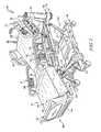
- FIG. 1is a perspective view of a patient support system including a patient support apparatus with a movable deck arranged in a partially-inclined configuration and a support surface mounted on the deck of patient support apparatus;
- FIG. 2is a diagrammatic view of the patient support system of FIG. 1 showing that the patient support apparatus includes an air source and a controller, and showing that the support surface includes a valve box and a plurality of bladders coupled to the valve box;
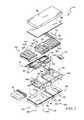
- FIG. 3is an exploded perspective view of the support surface of FIGS. 1 and 2 showing that the support surface includes (from bottom to top) a lower ticking, a foam shell, a fill bladder, lateral rotation bladders, support bladders, percussion and vibration therapy bladders, a fire barrier, and a low-air-loss topper;
- FIG. 4is a side elevation view of a first user interface panel included in the patient support apparatus of FIG. 1 ;
- FIG. 5is a side elevation view of a second user interface panel included in the patient support apparatus of FIG. 1 ;
- FIGS. 6-8are a series of partially diagrammatic side elevation views of the deck and the support surface showing the deck of the patient support apparatus moving from a flat configuration, shown in FIG. 6 , to a fully-inclined configuration, shown in FIG. 8 , and showing that the fill bladder of the support surface is configured to inflate in response to movement of the deck to fill a gap created in the support surface and a gap formed in the deck during movement to the fully-inclined configuration;
- FIG. 6is a partially diagrammatic side elevation view of the deck and the support surface showing the deck of the patient support apparatus includes a head-deck section, a seat deck section, a thigh-deck section, and a foot deck section arranged in the flat position, and showing that the fill bladder included in the mattress is deflated when the deck is arranged in the flat configuration;
- FIG. 7is a view similar to FIG. 6 showing the deck moved by pivoting and sliding to a partially-inclined position in which the head deck section is spaced apart from the seat deck section forming a gap in the support bladders of the support surface and a gap between the head deck section and the seat deck section, and showing that the fill bladder is partially-inflated when the deck is moved to the partially-inclined configuration to fill the gaps;
- FIG. 8is a view similar to FIGS. 6 and 7 , showing the deck moved by pivoting and sliding to a fully-inclined position in which the head deck section is further spaced apart from the seat deck section expanding the gap in the support bladders and the gap between the head deck section and the seat deck section, and showing that the fill bladder is inflated when the deck is moved to the fully-inclined configuration to fill the gap between the head deck section and the seat deck section;
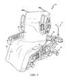
- FIG. 9is a perspective view of the patient support system moved to the chair-egress configuration in response to a caregiver pressing and holding a chair-egress button included in the first user interface panel (shown in FIG. 4 ) to reconfigure the patient support system for a patient exiting the patient support system,
- FIGS. 10-12are a series of partially diagrammatic side elevation views of the deck and the support surface showing the deck of the patient support apparatus moving from the fully inclined position, shown in FIG. 10 , to the chair-egress configuration, shown in FIG. 12 , and showing that bladders in the support surface deflate and inflate during movement from the fully-inclined configuration to the chair-egress configuration;
- FIG. 10is a is a partially diagrammatic side elevation view of the deck and the support surface showing a seat bladder and a foot bladder of the support surface deflated prior to the patient support apparatus moving from the fully inclined configuration toward the chair-egress configuration;
- FIG. 11is a view similar to FIG. 10 showing the deck moved to a chair-egress configuration and showing that the seat bladder and the foot bladder remain deflated;
- FIG. 12is a view similar to FIGS. 10 and 11 showing a turn bladder included in the surface underlying the patient's torso inflated to help push a patient exiting the patient support system to stand up out of the patient support system;
- FIG. 13is a perspective view of the patient support system moved to the side-egress configuration in response to a caregiver pressing and holding a side-egress button included in the second user interface panel (shown in FIG. 5 ) to reconfigure the patient support system with an upper frame of the patient support apparatus lowered and with a siderail of the patient support apparatus lowered to allow a patient to exit the patient support system along a side of the patient support system;
- FIGS. 14-16are a series of partially diagrammatic side elevation views of the deck and the support surface showing the deck of the patient support apparatus in the flat configuration and showing the support bladders of the support surface inflated to support a patient exiting the patient support system;
- FIG. 14is a is a partially diagrammatic side elevation view of the deck and the support surface showing the head bladder, the seat bladder, and the foot bladder inflated to a normal inflation level prior to sequenced inflation to support a patient exiting the patient support system;
- FIG. 15is a view similar to FIG. 14 showing head bladder and the foot bladder inflated to an exit inflation level to support a patient pushing down with his hands to push himself up during exit from the patient support system as suggested in FIG. 13 ;
- FIG. 16is a view similar to FIGS. 14 and 15 the seat bladder inflated to an exit inflation level, after the head and foot bladder are inflated to exit inflation levels, to help push a patient exiting the patient support system to stand up out of the patient support system;
- FIG. 17is a perspective view of the patient support system of FIG. 1 showing the support surface lifted up off of the patient support apparatus to expose the deck of the patient support apparatus;
- FIG. 17Ais a detail view of one of the lugs shown in FIG. 17 ;
- FIG. 17Bis a detail view of one of the lug-receiving apertures shown in FIG. 17 ;
- FIG. 17Cis a detail view of another of the lug-receiving apertures shown in FIG. 17 ;
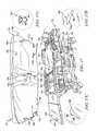
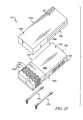
- FIG. 18is a bottom plan view of the support surface of FIGS. 1 and 17 showing the location of the lugs used to couple the support surface to the deck of the patient support apparatus;
- FIG. 19is a top plan view of the patient support apparatus of FIGS. 1 and 17 showing the location of the lug apertures formed in the deck to receive the lugs used to couple the support surface to the patient support apparatus;
- FIG. 20is a perspective view of the support surface of FIG. 1 showing components removed to expose the foam shell and to show that the foam shell includes a head portion formed to include line routing channels and a seat portion formed to include an entry port;
- FIG. 21is an enlarged perspective view of the foot bladder included in the support surface of FIGS. 1-3 showing that the foot bladder has a reduced thickness central section configured to conform to a patient's heel in response to a patient's foot resting on the foot bladder;
- FIG. 22is a cross-sectional view of the foot bladder in FIG. 21 taken at line 22 - 22 showing that the central section of the foot bladder has a gradually diminishing thickness while outer sections of the foot bladder have an equal thickness along the length of the foot bladder;
- FIG. 23is a perspective view of a second support surface configured for use with the patient support apparatus of FIG. 1 ;
- FIG. 24is a side elevation view of the second support surface shown in FIG. 23 ;
- FIG. 25is a perspective view of the second support surface of FIGS. 23 and 24 showing that the second support surface includes an outer ticking, an interior cushion, and a pair of frame straps;
- FIG. 26is an exploded perspective view of the interior cushion of FIG. 25 ;
- FIG. 27is a view similar to FIG. 6 showing an optional overlay adapted for use with the patient support system of FIGS. 1-22 ;
- FIG. 28is a view similar to FIG. 7 with the overlay of FIG. 27 mounted to the patient support system of FIGS. 1-22 ;
- FIG. 29is a view similar to FIG. 8 with the overlay of FIGS. 27 and 28 mounted to the patient support system of FIGS. 1-22 .
- a patient support systemis embodied as a hospital bed 10 including a patient support apparatus 12 (sometimes called a bed frame), a support surface 14 (sometimes called a mattress) mounted on the patient support apparatus 12 , and a control system 15 coupled to both the patient support apparatus 12 and to the support surface 14 .
- the patient support apparatus 12is reconfigurable to support a patient on the bed 10 in different positions.
- the support surface 14is adapted for use with the patient support apparatus 12 to support the patient in each different position induced by the patient support apparatus 12 and is configured to apply therapies to the patient while supported on the bed 10 .
- the control system 15controls movement of the patient support apparatus 12 and operation of the support surface 14 .
- the patient support apparatus 12illustratively includes a lower frame 16 , an upper frame 18 , and a lift system 20 coupled to the lower frame 16 and the upper frame 18 , as shown in FIG. 1 .
- the lift system 20includes a plurality of lift arms 21 , 22 , 23 , 24 and is configured to raise and lower the upper frame 18 relative to the lower frame 16 .
- the lift system 20is coupled to and controlled by the control system 15 as shown in FIG. 2 .
- the patient support apparatus 12also includes a deck 26 coupled to the upper frame 18 and repositionable to a plurality of positions as suggested in FIG. 1
- the deckis also coupled to and controlled by the control system 15 as shown in FIG. 2 .
- the head-deck section 30is mounted to the upper frame 18 to pivot about an axis relative to the seat-deck section 32 and to slide relative to the seat-deck section 32 and the upper frame 18 as described in U.S. Publication Nos. US 2010/0122415 A1 and US 2012/0005832 A1, both incorporated by reference herein in their entirety, except as they are inconsistent with the present disclosure.
- the seat-deck section 32is coupled to the upper frame 18 to move with the upper frame 18 .
- the thigh-deck section 34is coupled to the seat-deck section 32 to pivot relative to the seat-deck section 32 .
- the foot-deck section 36is coupled to the thigh-deck section 34 to pivot relative to the thigh-deck section 34 .
- the foot-deck section 36is also extendable and retractable to lengthen or shorten the deck 26 as desired by a caregiver or to accommodate repositioning of the deck 26 .
- the control system 15illustratively includes a controller 25 , a plurality of user interfaces 68 , 70 , 72 , 74 , 76 , a plurality of sensors 78 , and an air source 79 as shown in FIG. 2 .
- the controller 25illustratively includes a processor 61 and a memory 91 coupled to the processor 61 and including instructions to be executed by the processor 61 .
- the user interfaces 68 , 70 , 72 , 74 , 76are coupled to the controller 25 and communicate with the controller 25 .
- the sensors 78are also coupled to the controller 25 to communicate with the controller 25 .
- the air source 79is coupled to the controller 25 to communicate with the controller 25 and is configured to inflate bladders 42 included in the support surface 14 .
- Sensors 78illustratively include pressure sensors, load cells, and a potentiometers positioned throughout the bed 10 .
- the pressure sensorsare configured to detect the pressure in each bladder of the support surface.
- the load cellsare positioned between the upper frame 18 and the deck 26 and are configured to detect patient weight.
- the potentiometersare configured to detect the angle of the deck sections 30 , 32 , 34 , 46 and the angle of the upper frame 18 relative to the floor underlying the bed 10 .
- the support surface 14is coupled to the deck 26 and moves with the deck 26 as the deck 26 is repositioned.
- the support surface 14illustratively includes a foam shell 40 , a plurality of inflatable bladders 42 supported by the foam shell 40 , and a cover 44 encasing the foam shell 40 and the bladders 42 as shown in FIGS. 2 and 3 .
- the foam shell 40underlies the inflatable bladders 42 and supports the bladders 42 .
- the inflatable bladders 42are coupled to a valve box 45 included in the support surface 14 and are configured to be inflated and deflated to support and apply therapies to a patient on the support surface 14 .
- the cover 44encapsulates the foam shell 40 and the bladders 42 and accommodates movement of the foam shell 40 and the inflatable bladders 42 during repositioning of the deck 26 .
- the inflatable bladders 42 included in the support surface 14illustratively include support bladders 50 , rotation bladders 52 , percussion and vibration bladders 54 , and a fill bladder 56 as shown in FIGS. 2 and 3 .
- the support bladders 50are configured to be inflated to support a patient lying on the support surface 14 .
- the rotation bladders 52are positioned below the support bladders 50 and are configured to inflate to rotate a patient on the support surface 14 about a longitudinal axis 14 A of the support surface.
- the percussion and vibration bladders 54are positioned above the support bladders 50 and are configured to apply percussive and/or vibratory therapies to a patient lying on the support surface 14 .
- the fill bladder 56is located below the support bladders 50 and is configured to fill a gap G 1 formed between the support bladders 50 when the deck 26 of the patient support apparatus is repositioned as suggested in FIGS. 6-8 .
- the support bladders 50include head-support bladder 60 , seat-support bladder 62 , and foot-support bladder 64 as shown, for example, in FIGS. 2 and 3 .
- the head-support bladder 60 having a plurality of laterally extending inflatable cells 60 ′is located at a head end 65 of the support surface 14 .
- the foot-support bladder 64 having a plurality of laterally extending inflatable cells 64 ′is located at a foot end 66 of the support surface 14 and is encased in a cover 67 .
- the seat-support bladder 62 having a plurality of laterally extending inflatable cells 62 ′is located between the head-support bladders 60 and the foot-support bladders 64 .
- the rotation bladdersillustratively include left and right head-turn bladders 80 , 81 and seat-turn bladders 82 , 83 as shown in FIGS. 2 and 3 .
- the left and right head-turn bladders 80 , 81are arranged to lie under a patient's torso when the patient is lying on the bed 10 to turn the patient's torso along the longitudinal axis 14 A depending on which head-turn bladder 80 , 81 is inflated.
- the left and right seat-turn bladders 82 , 83are arranged to lie under a patient's seat and thighs when the patient is lying on the bed 10 to turn the patient's legs along the longitudinal axis 14 A depending on which seat-turn bladder 82 , 83 is inflated.
- the left head-turn bladder 80 and the left seat-turn bladder 82are plumbed together for concurrent inflation but in other embodiments may be separately plumbed.
- the right head-turn bladder 81 and the right seat-turn bladder 83are plumbed together for concurrent inflation but in other embodiments may be separately plumbed.
- the left and right head-turn bladders 80 , 81are spaced apart from the left and right seat turn bladders, 83 to accommodate formation of the gap G 2 when the deck 26 of the patient support apparatus is repositioned as suggested in FIGS. 6-8 .
- the cover 44illustratively includes a topper 86 , a fire barrier 88 , and a lower ticking 90 as shown in FIGS. 2 and 3 .
- the topper 86is illustratively a low-air-loss topper configured to conduct air along a top side 85 of the support surface 14 to influence the temperature and humidity of a patient's skin supported on the support surface 14 .
- the topper 86is coupled to the lower ticking 90 by a zipper and overlies the fire barrier 88 .
- the fire barrier 88is coupled to the lower ticking 90 and extends over the lower ticking to encase the foam shell 40 , the bladders 42 , and the valve box 45 inside the cover 44 .
- the lower ticking 90includes a head-end section 92 , a foot-end section 94 , and a series of folds 96 coupled to the head-end section 92 and the foot-end section 94 as shown in FIGS. 2 and 3 .
- the series of folds 96are configured to allow expansion of a bottom side 95 of the support surface 14 to accommodate formation of the gap G 1 between in the support bladders 50 and the gap G 2 between the deck sections 30 , 32 when the deck 26 of the patient support apparatus is repositioned as suggested in FIGS. 6-8 .
- the first user interface 70includes a battery level indicator 99 and a plurality of buttons 101 - 116 .
- Buttons 101 - 116are operable by a caregiver to reconfigure the bed 10 by communicating with the controller to operate the deck 26 , the lift system 20 , the valve box 45 , and the air supply 79 .
- the first user interface 70includes the following buttons:
- the second user interface 72includes a plurality of buttons 117 - 124 .
- Buttons 117 - 124are operable by a caregiver to reconfigure the bed 10 by communicating with the controller to operate the deck 26 , the lift system 20 , the valve box 45 , and the air supply 79 .
- the first user interface 70includes the following buttons:
- FIGS. 6-8the deck 26 of the patient support apparatus 12 is shown moving from a flat position (shown in FIG. 6 ) to a fully-inclined position (shown in FIG. 8 ) and showing that the fill bladder 56 of the support surface 14 is inflated to fill the gap G 1 formed in the support surface 14 and the gap G 2 created in the deck 26 during movement to the fully-inclined position. More particularly, when a caregiver presses one of the head-deck incline buttons 110 , 119 , the controller 25 operates the deck 26 so that the head-deck section 30 pivots and slides relative to the seat-deck section 32 to form in inclined angle with the seat-deck section 32 .
- the gap G 2expands as shown in FIGS. 7 and 8 .
- the gap G 1 between the head-support bladders 60 and the seat-support bladders 62is formed when the head-support bladders 60 move with the head-deck section 30 away from the seat-deck section 32 .
- the controller 25is configured to inflate the fill bladder 56 to a level corresponding to the movement of the head-deck section 30 relative to the seat-deck section 32 as suggested in FIGS. 7 and 8 .
- the controller 25operates the air source 79 and the valve box 45 to inflate the fill bladder 56 to a partially inflated state.
- the controlleroperates the air source 79 to inflate the fill bladder 56 to a fully inflated state.
- the folds 96 of the lower ticking 90are expand during movement of the head-deck section 30 away from the seat-deck section 32 .
- the expansion of the folds 96 between the head-end section 92 and the foot-end section 94 of the lower ticking 90prevents tearing or over-stretching of the lower ticking 90 during movement of the deck 26 .
- the bed 10is shown moved to the chair-egress configuration.
- the controller 25operates the lift system 20 to lower the upper frame 18 .
- the controller 25also operates the deck 26 to lower the foot-deck section 36 and raise the head-deck section 30 as shown in FIGS. 11-12 .
- the controller 25is configured to determine if the footboard of the patient-support apparatus 12 has been removed. Then the controller operates the deck 26 to move the patient support apparatus 12 to a full chair configuration. Once the full chair position is reached, the controller 25 is configured to operate the valve box 45 to deflate the seat-support bladder 62 and the foot-support bladder 64 prior to moving the upper frame 18 and the deck 26 as suggested in FIG. 10 . When the seat-support bladder 62 is deflated, the controller 25 is configured to lower the upper frame 18 , lower the foot-deck section 36 , and raise the head-deck section 30 to the chair-egress configuration as shown in FIG. 11 .
- the controller 25coordinates movement of the deck 26 to the chair egress position with deflation of the seat-support bladder 62 and the foot-support bladder 64 . More specifically, the controller 25 simultaneously moves the deck 26 toward the chair egress position while deflating the seat-support bladder 62 and the foot-support bladder 64 . During movement of the deck 26 and deflation of the seat-support bladder 62 and the foot-support bladder 64 , the controller 25 monitors progress of deflation via pressure sensors in the seat-support bladder 62 and the foot-support bladder 64 .
- the controller 25may slow or pause movement of the deck 26 if pressure in the seat-support bladder 62 and the foot-support bladder 64 are not at a predetermined level corresponding to the position of the deck 26 or if the pressure is not dropping at a predetermined rate. Further, the controller 25 may stop movement of the deck 26 and trigger an alarm to communicate an error or a fault to a caregiver if deflation of the seat-support bladder 62 and the foot-support bladder 64 is not progressing. Thus, the controller 26 prevents movement of the deck 26 to the chair egress position without full deflation of the seat-support bladder 62 and the foot-support bladder 64 . Similarly, the controller 25 may coordinate movement of the deck 26 from the chair egress position to the flat position with inflation of the seat-support bladder 62 and the foot-support bladder 64 .
- a patient supported on the bed 10is lowered and supported on the hard surface of the seat-deck section 32 and the thigh-deck section 34 when the chair-egress configuration is reached.
- Supporting the patient on the hard surfaces of the seat-deck section and the thigh-deck section 34provides stability to the patient so that the patient can stand up out of the bed 10 .
- the foot-support bladder 64is deflated, the patient is able to place her feet on the floor adjacent to the foot-deck section 36 when exiting the bed 10 as suggested in FIG. 12 .
- the controller 25is configured to operate the valve box 45 to inflate the head-turn rotation bladders 80 , 81 to assist a patient exiting the bed 10 as suggested in FIG. 12 .
- the head-turn rotation bladders 80 , 81to a push-pressure determined by the controller 25 .
- the push-pressurea pressure based at least in part on the most recent patient weight determined by the controller 25 .
- the bed 10is shown moved to the side-egress configuration.
- the controller 25operates the lift system 20 to lower the upper frame 18 .
- the controller 25also operates the deck 26 to flatten the deck 26 as shown in FIG. 13 .
- the controller 25is configured to operate the valve box 45 and the air source 79 to inflate the head-support bladder 60 and the foot-support bladder 64 to an exit pressure as shown in FIG. 15 . Additionally, the rotation bladders 52 are inflated to exit pressures. When the head-support bladder 60 and the foot-support bladder 64 are inflated, the controller 25 is configured to inflate the seat-support bladder 62 to an exit pressure to assist a patient exiting the bed 10 as suggested in FIG. 16 . Exit pressures of the support bladders 60 , 62 , 64 are generally greater than normal operating pressures as further described below.
- the algorithm for determining the exit pressures of the head-support bladder 60 , the seat-support bladder 62 , and the foot support bladder 64are dependent upon patient weight determined by the controller 25 based, at least in part, on information from the load cells sensors 78 .
- the support surface 14is coupled to the patient support apparatus 12 by a plurality of lugs 130 - 135 received in corresponding lug-receiver apertures 136 - 141 .
- a first pair of lugs 130 , 131is coupled to the head-end section 92 of the lower ticking 90 along the head end 65 of the support surface 14 .
- the first pair of lugs 130 , 131is received in a corresponding pair of keyhole slots 136 , 137 formed in the head-deck section 30 of the deck 26 as suggested in FIGS. 17-19 .
- a second pair of lugs 132 , 133is coupled to the foot-end section 94 of the lower ticking 90 along the foot end 66 of the support surface 14 .
- the second pair of lugs 132 , 133are received in a corresponding pair of keyhole slots 138 , 139 formed in the foot-deck section 36 of the deck 26 as suggested in FIGS. 17-19 .
- a third pair of lugs 134 , 135is coupled to the ticking 90 between the head end 65 and the foot end 66 of the support surface 14 .
- the third pair of lugs 130 , 131is received in a corresponding pair of notches 140 , 141 formed in the seat-deck section 32 of the deck 26 as suggested in FIGS. 17-19 .
- each lugincludes a stem 142 and a ball 144 coupled to the stem and spaced apart from the lower ticking 90 .
- the stems 142extend through the deck 26 and the balls 144 are trapped below the deck 26 by the lug-receiver apertures 136 - 141 when the support surface 14 is mounted on the patient support apparatus 12 .
- the keyhole slots 136 , 137 , 138 , 139have a wide portion 146 and a narrow portion 148 as shown in FIGS. 17B and 17C .
- the wide portions 146are illustratively located inwardly of the narrow portions 148 as shown in FIG. 19 .
- the support surface 14includes a trunk 150 extending downwardly from the foot-end section 94 of the lower ticking 90 as shown in FIG. 17 .
- the seat-deck section 32is formed to include a channel 152 extending downwardly toward the floor underlying the bed 10 and arranged to receive the trunk 150 of the support surface 14 as suggested in FIGS. 17-19 .
- the trunk 150includes air lines and communication lines for coupling the controller 25 and the air source 79 to the support surface 14 as shown in FIG. 2 .
- the foam shell 40illustratively includes a head shell 160 and a seat shell 162 as shown in FIGS. 3 and 20 .
- the head shell 160is formed to include a left channel 164 and a right channel 166 arranged to extend along the sides of the support surface 14 to provide a path for air and communication lines to pass from the valve box 45 along the interior of the support surface 14 .
- the seat shell 162is formed to include a line aperture 165 extending through the seat shell 162 to allow air and communication lines inside the support surface 14 to be connected with the trunk 150 of the support surface 14 . Additionally, the seat shell 162 is formed to include a left channel 168 and a right channel 170 arranged to extend along the sides of the support surface 14 to provide a path for air and communication lines to pass from the line aperture 165 along the interior of the support surface 14 toward the head end 65 and the foot end 66 of the support surface 14 .
- the foot-support bladder 64illustratively includes a plurality of cells 181 , 182 , 183 , 184 , 185 , 186 that cooperate to form a left rail section 172 , a right rail section 174 , and a central section 176 .
- the left and the right rail sections 172 , 174 of the foot-support bladder 64have a substantially similar cross-sectional area as shown in FIGS. 21, 22 .
- the central section 176has a diminishing cross-sectional area moving toward the foot end 66 of the support surface 14 as suggested in FIGS. 21 and 22 .
- the result of the diminishing cross-sectional areais the formation of a space 175 formed under a portion of the central section 176 that allows for bucking of the foot-support bladder 64 when a patient's heel is supported on the central section 176 .
- Buckling of the cells 181 - 186adds the surface area of the foot-support bladder 64 in contact with the heel and foot of a patient. Therefore, the local pressure on the skin is reduced as the patient's feet are partially immersed in the foot-support bladder 64 .
- the patient support apparatus 12includes siderails 71 , 73 coupled to the seat-deck section 32 and headrails 75 , 77 coupled to the head-deck section 30 .
- the patient support apparatus 12also includes a headboard 19 coupled to the upper frame 18 and a removable footboard 37 coupled to the foot-deck section 36 .
- the controller 25is configured to move the bed 10 to the chair-egress configuration only if the footboard 37 is removed from the foot-deck section 36 . If the footboard 37 is not removed and a user requests the chair-egress position, an instructional screen appears on the user interface 74 suggesting that the caregiver remove the footboard 37 .
- the user interface 68is a push-button panel coupled to an inner side of the siderail 71 included in the patient support apparatus 12 .
- the user interface 70is a push-button panel pivotably coupled to an outer side of the siderail 73 included in the patient support apparatus 12 .
- the user interface 72is a push-button panel coupled to an outer side of the headrail 77 .
- the user interface 74is a touch screen graphical user interface coupled to the outer side of the side rail 73 .
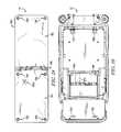
- the support surface 214has a head end 215 , a foot end 216 , a left side 217 and a right side 218 as shown in FIGS. 23 and 24 .
- the support surface 214illustratively includes an outer ticking 290 , an interior cushion 250 , and a pair of frame straps 291 , 293 as shown in FIG. 25 .
- the outer ticking 290encases the interior cushion 250 as shown in FIG. 24 .
- the interior cushion 250supports a patient lying on the support surface 214 . Both the outer ticking 290 and the interior cushion 250 are configured to accommodate movement of the deck 26 from the flat position (shown in FIG. 6 ) to the fully-inclined position (shown in FIG. 8 ) without including an inflatable fill bladder.
- the outer ticking 290illustratively includes a head-end section 292 , a foot-end section 294 , and an elastic section 296 coupled to the head-end section 292 and the foot-end section 294 as shown in FIGS. 23-25 .
- the elastic section 296is configured to allow expansion of a bottom side 295 of the support surface 214 to accommodate formation of the gap G 2 between the deck sections 30 , 32 when the deck 26 of the patient support apparatus 12 is repositioned as suggested in FIGS. 6-8 .
- the outer ticking 290may include a plurality of expandable folds similar to the expandable folds 96 described herein in place of the elastic section 296 .
- the interior cushion 250illustratively includes a top pad 252 , a head pad 254 , an air pad 256 , a knee joint pad assembly 258 , a foot pad 260 , an expandable bottom pad 262 , and a pair of side bolsters 264 , 266 .
- the top pad 252 , the head pad 254 , the knee joint pad assembly 258 , the foot pad 260 , the expandable bottom pad 262 , and the side bolsters 264 , 266are made from foam.
- the air pad 256includes a plurality of sealed air cells 270 each containing a foam pad 272 .
- the top pad 252forms a portion of a top surface 268 of the cushion 250 and is arranged to extend from the head end 215 of the surface 214 toward the foot end 216 of the patient support surface 214 as shown in FIGS. 25 and 26 .
- the head pad 254underlies the top pad 252 and is arranged to extend from the head end 215 of the patient support surface 214 toward the foot end 216 of the surface 214 .
- the air pad 256underlies the top pad 252 and extends from the head pad 254 toward the foot end 216 of the surface 214 .
- the knee joint pad assembly 258also underlies the top pad 252 and a portion of the foot pad 260 .
- the knee joint pad assembly 258extends between the air pad 256 and the foot pad 260 .
- the expandable bottom pad 262forms a portion of a bottom surface 269 of the cushion 250 and underlies the top pad 252 , the head pad 254 , the air pad 256 , the knee joint pad assembly 258 , a portion of the foot pad 260 and the side bolsters 264 , 266 as shown in FIGS. 25 and 26 .
- the expandable bottom pad 262extends from the head end 215 of the surface 214 toward the foot end 216 of the surface 214 .
- the side bolsters 264 , 266underlie the top pad 252 and a portion of the foot pad 260 .
- the side bolsters 264 , 266further extend from the head end 215 of the surface 214 toward the foot end 216 of the surface 214 along the left and right sides 217 , 218 , respectively, of the surface 214 .
- the knee-joint pad assembly 258illustratively includes a knee block 274 , a first knee wedge 276 , and a second knee wedge 278 as shown in FIG. 26 .
- the knee wedges 276 , 278underlie the knee block 274 and cooperate to provide a joint between the air pad 256 and the foot pad 260 to facilitate bending of the surface 214 when the foot deck section 36 pivots relative to the thigh deck section 34 of the deck 26 as suggested in FIG. 1 .
- the foot pad 260forms a portion of the top and bottom surfaces 268 , 269 of the cushion 250 as shown in FIGS. 25 and 26 .
- the foot pad 260is formed to include a plurality of perforations 279 extending from the top surface 268 to the bottom surface 269 of the cushion 250 .
- the perforations 279expand to allow extension of the foot pad 260 when the foot deck section 36 is extended and to allow retraction of the foot pad 260 when the foot deck section 36 is retracted.
- the perforations 279may also reduce interface pressure between a patient's feet and the surface 214 to reduce the risk of pressure ulcer formation on the patient's feet.
- the expandable bottom pad 262includes a perforated portion 280 and a solid portion 282 as shown in FIG. 26 .
- the perforated portion 280extends from the head end 215 of the surface 214 toward the foot end 216 of the surface 214 to overlie the head deck section 30 of the deck 26 when the surface 214 is mounted on the patient support apparatus 12 .
- the solid portion 282extends from the perforated portion 280 toward the foot end 216 of the surface 214 to overlie the seat deck section 32 of the deck 26 .
- the perforated portion 280 of the expandable bottom pad 262is formed to include a plurality of perforations 285 as shown in FIG. 26 .
- the perforations 285extend through the expandable bottom pad 262 from the bottom surface 269 of the cushion 250 toward the top surface 268 of the cushion 250 .
- the perforations 285expand during movement of the deck 26 from the flat position (shown in FIG. 6 ) to the fully-inclined position (shown in FIG. 8 ) so that the gap G 2 formed between the head deck section 30 and the seat deck section 32 is covered.
- the surface 214is prevented from buckling or bunching into the gap G 2 when the head deck section 30 moves away from the seat deck section 32 .
- Each of the side bolsters 264 , 266is formed to include a plurality of top-side slits 286 and bottom-side slits 288 as shown in FIG. 26 .
- the top-side slits 286extend from a top side 287 of the bolsters 264 , 266 toward a bottom side 269 of the bolsters 264 , 266 .
- the bottom-side slits 288extend from the bottom side 269 toward the top side 267 of the bolsters 264 , 266 .
- the top-side slits 286 and the bottom-side slits 288expand during movement of the deck 26 from the flat position to the fully-inclined position.
- the patient support surface 214also includes a plurality of lugs 231 - 234 configured to be received in corresponding lug-receiver apertures 136 - 139 included in the deck 26 of the patient support apparatus 12 .
- a first pair of lugs 231 , 232is coupled to the head-end section 292 of the ticking 290 and to the expandable bottom pad 262 of the cushion 250 along the head end 215 of the support surface 214 .
- the first pair of lugs 231 , 232is configured to be received in the corresponding pair of keyhole slots 136 , 137 formed in the head-deck section 30 of the deck 26 shown in FIG. 17 .
- a second pair of lugs 233 , 234is coupled to the foot-end section 294 of the ticking 90 and to the foot pad 260 along the foot end 216 of the support surface 214 .
- the second pair of lugs 233 , 234are received in the corresponding pair of keyhole slots 138 , 139 formed in the foot-deck section 36 of the deck 26 shown in FIG. 17 .
- the overlay 310illustratively includes a head portion 312 , a foot portion 314 , and an expandable portion 316 arranged between the head portion 312 and the foot portion 314 .
- the overlay 310also has a low-friction underside 318 that engages the top side of the patient support surface 14 .
- the expandable portion 316includes a plurality of expandable folds 320 but in other embodiments may be an elastic material.
- the expandable portion 316 of the overlay 310expands during movement of the deck 26 from the flat position (shown in FIG. 27 ) to the fully-inclined position (shown in FIG. 29 ).
- the overlay 310operates to further support a patient over the gaps G 1 and gap G 2 formed in the deck 26 and the surface 14 .
- the low-friction surface 318 of the overlay 310is allowed to slide slightly relative to the surface 14 as suggested by arrow 321 thereby relieving additional shear stresses that might be applied to a patient's skin during movement from the flat position to the fully-inclined position.
Landscapes
- Health & Medical Sciences (AREA)
- Nursing (AREA)
- Life Sciences & Earth Sciences (AREA)
- Animal Behavior & Ethology (AREA)
- General Health & Medical Sciences (AREA)
- Public Health (AREA)
- Veterinary Medicine (AREA)
- Physics & Mathematics (AREA)
- General Physics & Mathematics (AREA)
- Rehabilitation Therapy (AREA)
- Invalid Beds And Related Equipment (AREA)
- Accommodation For Nursing Or Treatment Tables (AREA)
Abstract
Description
- Chair-
egress button 101 for reconfiguring thebed 10 to a chair-egress configuration as shown inFIG. 9 , - Return-to-
flat button 102 for reconfiguring thebed 10 from a non-flat configuration (such as chair-egress) to a flat position, Trendelenberg button 103 for reconfiguring thebed 10 to a Trendelenberg configuration,- Reverse-
Trendelenberg button 104 for reconfiguring thebed 10 to a reverse-Trendelenberg configuration, - Pull-up-in-
bed button 105 for flattening the deck and raising thefoot end 66 of thedeck 26 above thehead end 65 of thedeck 26 to assist a caregiver pulling a patient up in thebed 10, - Foot-
raise button 106 for raising the foot-deck section 36 as suggested by the icon on the foot-raise button 106, - Foot-
lower button 107 for lowering the foot-deck section 34 as suggested by the icon on the foot-lower button 107, - Foot-extend
button 108 for extending the foot-deck section 36, - Foot-retract
button 109 for retracting the foot-deck section 36, - Head-
deck incline button 110 for increasing the incline of the head-deck section 30 by pivoting the head-deck section 30 relative to the seat-deck section 32 and sliding the head-deck section 30 relative to the seat-deck section 32 and theupper frame 18 as suggested inFIGS. 6-8 , - Head-
deck decline button 111 for decreasing the incline of the head-deck section 30, - Thigh-
deck incline button 112 for increasing the incline of the thigh-deck section 34, - Thigh-
deck decline button 113 for decreasing the incline of the thigh-deck section 34, - Upper-
frame raise button 114 for lifting theupper frame 18 relative to thelower frame 16, - Upper-frame
lower button 115 for lowering theupper frame 18 relative to thelower frame 16, and Unlock button 116 for activating the functions of buttons101-115 in response to holding downunlock button 116 to prevent unwanted activation of buttons101-113.
- Chair-
- Side-
egress button 117 for reconfiguring thebed 10 to a side-egress configuration as shown inFIG. 13 , - Return-to-
rest button 118 for returning thebed 10 to a resting configuration from the side-egress configuration, - Head-
deck incline button 119 for increasing the incline of the head-deck section 30 by pivoting the head-deck section 30 relative to the seat-deck section 32 and sliding the head-deck section 30 relative to the seat-deck section 32 and theupper frame 18 as suggested inFIGS. 6-8 , - Head-
deck decline button 120 for decreasing the incline of the head-deck section 30, - Thigh-
deck incline button 121 for increasing the incline of the thigh-deck section 34, - Thigh-
deck decline button 122 for decreasing the incline of the thigh-deck section 34, - Upper-
frame raise button 123 for lifting theupper frame 18 relative to thelower frame 16, and - Upper-frame
lower button 124 for lowering theupper frame 18 relative to thelower frame 16.
- Side-
Head Exit Pressure=(15/400)*PWSP+14, up to 32
Seat Exit Pressure=(15/400)*PWSP+14, up to 32
Foot Exit Pressure=(15/400)*PWSP+14, up to 32
Rotation Exit Pressure=2
Claims (18)
Priority Applications (14)
| Application Number | Priority Date | Filing Date | Title |
|---|---|---|---|
| US13/828,186US9329076B2 (en) | 2012-06-21 | 2013-03-14 | Patient support systems and methods of use |
| PCT/US2013/046796WO2013192411A2 (en) | 2012-06-21 | 2013-06-20 | Patient support systems and methods of use |
| JP2015518577AJP6017686B2 (en) | 2012-06-21 | 2013-06-20 | Patient holding system and method of use |
| US14/409,271US9833369B2 (en) | 2012-06-21 | 2013-06-20 | Patient support systems and methods of use |
| US13/922,979US9618383B2 (en) | 2012-06-21 | 2013-06-20 | Patient support systems and methods of use |
| EP13807132.9AEP2863858A4 (en) | 2012-06-21 | 2013-06-20 | PATIENT SUPPORT SYSTEMS AND METHODS OF USE |
| US13/922,982US9655457B2 (en) | 2012-06-21 | 2013-06-20 | Patient support systems and methods of use |
| JP2016189168AJP2017060773A (en) | 2012-06-21 | 2016-09-28 | Patient support systems and methods of use |
| US15/425,391US10391008B2 (en) | 2012-06-21 | 2017-02-06 | Patient support system and methods of use |
| US15/499,424US10555850B2 (en) | 2012-06-21 | 2017-04-27 | Patient support systems and methods of use |
| US15/784,281US10806655B2 (en) | 2012-06-21 | 2017-10-16 | Mattress bladder control during patient bed egress |
| US16/513,872US11116681B2 (en) | 2012-06-21 | 2019-07-17 | Patient support systems and methods of use |
| US17/024,858US12102577B2 (en) | 2012-06-21 | 2020-09-18 | Mattress bladder control using a bleed valve |
| US18/820,620US20240423852A1 (en) | 2012-06-21 | 2024-08-30 | Mattress bladder arrangement for patient bed |
Applications Claiming Priority (5)
| Application Number | Priority Date | Filing Date | Title |
|---|---|---|---|
| US201261662711P | 2012-06-21 | 2012-06-21 | |
| US201261663311P | 2012-06-22 | 2012-06-22 | |
| US201261722663P | 2012-11-05 | 2012-11-05 | |
| US13/798,359US9228885B2 (en) | 2012-06-21 | 2013-03-13 | Patient support systems and methods of use |
| US13/828,186US9329076B2 (en) | 2012-06-21 | 2013-03-14 | Patient support systems and methods of use |
Related Parent Applications (2)
| Application Number | Title | Priority Date | Filing Date |
|---|---|---|---|
| US13/798,359Continuation-In-PartUS9228885B2 (en) | 2012-06-21 | 2013-03-13 | Patient support systems and methods of use |
| US13/798,359ContinuationUS9228885B2 (en) | 2012-06-21 | 2013-03-13 | Patient support systems and methods of use |
Related Child Applications (4)
| Application Number | Title | Priority Date | Filing Date |
|---|---|---|---|
| US13/798,359Continuation-In-PartUS9228885B2 (en) | 2012-06-21 | 2013-03-13 | Patient support systems and methods of use |
| US13/922,979Continuation-In-PartUS9618383B2 (en) | 2012-06-21 | 2013-06-20 | Patient support systems and methods of use |
| US13/922,982ContinuationUS9655457B2 (en) | 2012-06-21 | 2013-06-20 | Patient support systems and methods of use |
| US15/784,281Continuation-In-PartUS10806655B2 (en) | 2012-06-21 | 2017-10-16 | Mattress bladder control during patient bed egress |
Publications (2)
| Publication Number | Publication Date |
|---|---|
| US20140123390A1 US20140123390A1 (en) | 2014-05-08 |
| US9329076B2true US9329076B2 (en) | 2016-05-03 |
Family
ID=50620988
Family Applications (7)
| Application Number | Title | Priority Date | Filing Date |
|---|---|---|---|
| US13/798,359Active2033-12-27US9228885B2 (en) | 2012-06-21 | 2013-03-13 | Patient support systems and methods of use |
| US13/828,186Active2033-05-09US9329076B2 (en) | 2012-06-21 | 2013-03-14 | Patient support systems and methods of use |
| US13/922,982Active2033-08-17US9655457B2 (en) | 2012-06-21 | 2013-06-20 | Patient support systems and methods of use |
| US13/922,979Active2034-09-28US9618383B2 (en) | 2012-06-21 | 2013-06-20 | Patient support systems and methods of use |
| US15/425,391Active2033-06-26US10391008B2 (en) | 2012-06-21 | 2017-02-06 | Patient support system and methods of use |
| US15/499,424Active2034-02-19US10555850B2 (en) | 2012-06-21 | 2017-04-27 | Patient support systems and methods of use |
| US16/513,872Active2033-05-21US11116681B2 (en) | 2012-06-21 | 2019-07-17 | Patient support systems and methods of use |
Family Applications Before (1)
| Application Number | Title | Priority Date | Filing Date |
|---|---|---|---|
| US13/798,359Active2033-12-27US9228885B2 (en) | 2012-06-21 | 2013-03-13 | Patient support systems and methods of use |
Family Applications After (5)
| Application Number | Title | Priority Date | Filing Date |
|---|---|---|---|
| US13/922,982Active2033-08-17US9655457B2 (en) | 2012-06-21 | 2013-06-20 | Patient support systems and methods of use |
| US13/922,979Active2034-09-28US9618383B2 (en) | 2012-06-21 | 2013-06-20 | Patient support systems and methods of use |
| US15/425,391Active2033-06-26US10391008B2 (en) | 2012-06-21 | 2017-02-06 | Patient support system and methods of use |
| US15/499,424Active2034-02-19US10555850B2 (en) | 2012-06-21 | 2017-04-27 | Patient support systems and methods of use |
| US16/513,872Active2033-05-21US11116681B2 (en) | 2012-06-21 | 2019-07-17 | Patient support systems and methods of use |
Country Status (1)
| Country | Link |
|---|---|
| US (7) | US9228885B2 (en) |
Cited By (9)
| Publication number | Priority date | Publication date | Assignee | Title |
|---|---|---|---|---|
| US20170224560A1 (en)* | 2012-06-21 | 2017-08-10 | Hill-Rom Services, Inc. | Patient support systems and methods of use |
| US20190000700A1 (en)* | 2017-06-29 | 2019-01-03 | Encompass Group, Llc. | Hospital bed with inflatable bladders and cooling channels and related methods |
| US10765225B2 (en)* | 2012-04-10 | 2020-09-08 | Hill-Rom Services, Inc. | Occupant support with a migration sensitive bladder and method for migration detection |
| US10806655B2 (en) | 2012-06-21 | 2020-10-20 | Hill-Rom Services, Inc. | Mattress bladder control during patient bed egress |
| US11052005B2 (en) | 2017-09-19 | 2021-07-06 | Stryker Corporation | Patient support apparatus with handles for patient ambulation |
| US11116680B2 (en) | 2017-09-19 | 2021-09-14 | Stryker Corporation | Patient support apparatus for controlling patient ingress and egress |
| US11160705B2 (en) | 2017-10-20 | 2021-11-02 | Stryker Corporation | Adjustable patient support apparatus for assisted egress and ingress |
| US11357683B2 (en)* | 2005-07-08 | 2022-06-14 | Hill-Rom Services, Inc. | Foot zone of a mattress |
| US12102577B2 (en) | 2012-06-21 | 2024-10-01 | Hill-Rom Services, Inc. | Mattress bladder control using a bleed valve |
Families Citing this family (82)
| Publication number | Priority date | Publication date | Assignee | Title |
|---|---|---|---|---|
| BR0016875A (en)* | 1999-12-29 | 2003-06-17 | Hill Rom Services Inc | Patient support, patient-configured mattress, patient support method, method of maintaining a patient's heel pressure relief, pressure system for use with a patient support mattress, and patient support frame |
| US9038217B2 (en)* | 2005-12-19 | 2015-05-26 | Stryker Corporation | Patient support with improved control |
| US7690059B2 (en)* | 2005-12-19 | 2010-04-06 | Stryker Corporation | Hospital bed |
| US11246776B2 (en) | 2005-12-19 | 2022-02-15 | Stryker Corporation | Patient support with improved control |
| WO2007092886A2 (en) | 2006-02-08 | 2007-08-16 | Hill-Rom Services, Inc. | User module for a patient support |
| CN103945812B (en)* | 2011-11-22 | 2017-06-30 | 八乐梦床业有限公司 | bed device |
| US20140310876A1 (en)* | 2011-12-16 | 2014-10-23 | Chg Hospital Beds Inc. | Patient support overload or obstruction detection |
| US9358168B2 (en) | 2012-09-04 | 2016-06-07 | Hill-Rom Services, Inc. | Patient position detection for patient support surface |
| US9782005B2 (en) | 2014-07-25 | 2017-10-10 | Stryker Corporation | Medical support apparatus |
| US10474808B2 (en) | 2013-03-29 | 2019-11-12 | Hill-Rom Services, Inc. | Hospital bed compatibility with third party application software |
| US10290071B2 (en) | 2013-03-29 | 2019-05-14 | Hill-Rom Services, Inc. | Universal caregiver interface |
| US9377345B2 (en)* | 2013-09-11 | 2016-06-28 | Illinois Tool Works Inc. | Food product scale |
| US10390737B2 (en) | 2013-09-30 | 2019-08-27 | Stryker Corporation | System and method of controlling a robotic system for manipulating anatomy of a patient during a surgical procedure |
| US10342358B1 (en)* | 2014-10-16 | 2019-07-09 | Sleep Number Corporation | Bed with integrated components and features |
| CN104606008A (en)* | 2015-01-29 | 2015-05-13 | 钟少平 | Multifunctional foldable rehabilitation nursing bed |
| DE102015208215B4 (en) | 2015-05-04 | 2024-05-02 | Stabilus Gmbh | Electromechanical control arrangement for a chair |
| CN118078551A (en)* | 2015-05-29 | 2024-05-28 | 希尔-罗姆服务公司 | Patient support equipment |
| US10695246B2 (en) | 2015-07-28 | 2020-06-30 | Stryker Corporation | Person support apparatus barrier |
| US11020297B2 (en) | 2015-12-22 | 2021-06-01 | Stryker Corporation | Powered side rail for a patient support apparatus |
| CH712316A1 (en)* | 2016-04-04 | 2017-10-13 | Lantal Textiles Ag | Vehicle seat with at least one pneumatic cushion. |
| CN106137622A (en)* | 2016-08-08 | 2016-11-23 | 李伏林 | All postural medical treatment and nursing platform |
| CN109952084B (en)* | 2016-10-31 | 2021-08-20 | 瓦鲁加控股私人有限公司 | Lifting system with lifting device and overhanging support platform |
| BR102017001670B1 (en)* | 2017-01-26 | 2021-01-12 | Kléber Elias Tavares | oscillating bed for the prevention of decubitus ulcers |
| US10856668B2 (en)* | 2017-04-10 | 2020-12-08 | Hill-Rom Services, Inc. | Mattress overlay control system with rotary valves and graphical user interface for percussion and vibration, turn assist and microclimate management |
| US11090209B2 (en) | 2017-06-20 | 2021-08-17 | Stryker Corporation | Patient support apparatus with control system and method to avoid obstacles during reconfiguration |
| US11202729B2 (en) | 2017-06-27 | 2021-12-21 | Stryker Corporation | Patient support apparatus user interfaces |
| US11484451B1 (en) | 2017-06-27 | 2022-11-01 | Stryker Corporation | Patient support apparatus user interfaces |
| US11810667B2 (en)* | 2017-06-27 | 2023-11-07 | Stryker Corporation | Patient support systems and methods for assisting caregivers with patient care |
| JP6869925B2 (en)* | 2017-07-27 | 2021-05-12 | ヒル−ロム サービシズ,インコーポレイテッド | Dynamic foam mattress suitable for use in hospital beds of varying length |
| US11033117B2 (en) | 2017-07-27 | 2021-06-15 | Hill-Rom Services, Inc. | Dynamic foam mattress adapted for use with a variable length hospital bed |
| US11173085B2 (en) | 2017-12-28 | 2021-11-16 | Stryker Corporation | Mattress cover for a mattress providing rotation therapy to a patient |
| US11246775B2 (en) | 2017-12-28 | 2022-02-15 | Stryker Corporation | Patient turning device for a patient support apparatus |
| US11213443B2 (en) | 2017-12-29 | 2022-01-04 | Stryker Corporation | Indication system to identify open space beneath patient support apparatus |
| CN108283544A (en)* | 2018-03-20 | 2018-07-17 | 王从相 | A kind of medical sickbed of transhipment patient |
| DE102018205758A1 (en)* | 2018-04-16 | 2019-10-17 | Siemens Healthcare Gmbh | Medical device and method for operating a medical device |
| CN108524131A (en)* | 2018-04-20 | 2018-09-14 | 谢文 | A kind of paediatrics is used convenient for the multifunctional hospital bed of children's bunk bed |
| USD879966S1 (en) | 2018-09-28 | 2020-03-31 | Stryker Corporation | Crib assembly |
| USD901940S1 (en) | 2018-09-28 | 2020-11-17 | Stryker Corporation | Patient support |
| USD977109S1 (en) | 2018-09-28 | 2023-01-31 | Stryker Corporation | Crib assembly for a patient support |
| USD888962S1 (en) | 2018-09-28 | 2020-06-30 | Stryker Corporation | Cover assembly for a patient support |
| USD888964S1 (en) | 2018-09-28 | 2020-06-30 | Stryker Corporation | Crib assembly for a patient support |
| USD888963S1 (en) | 2018-09-28 | 2020-06-30 | Stryker Corporation | Cover assembly for a patient support |
| USD877915S1 (en) | 2018-09-28 | 2020-03-10 | Stryker Corporation | Crib assembly |
| USD1041511S1 (en) | 2018-10-11 | 2024-09-10 | Masimo Corporation | Display screen or portion thereof with a graphical user interface |
| USD999246S1 (en)* | 2018-10-11 | 2023-09-19 | Masimo Corporation | Display screen or portion thereof with a graphical user interface |
| USD917564S1 (en)* | 2018-10-11 | 2021-04-27 | Masimo Corporation | Display screen or portion thereof with graphical user interface |
| US11406286B2 (en) | 2018-10-11 | 2022-08-09 | Masimo Corporation | Patient monitoring device with improved user interface |
| USD998631S1 (en)* | 2018-10-11 | 2023-09-12 | Masimo Corporation | Display screen or portion thereof with a graphical user interface |
| USD892159S1 (en) | 2018-10-31 | 2020-08-04 | Stryker Corporation | Display screen with animated graphical user interface |
| USD894956S1 (en) | 2018-10-31 | 2020-09-01 | Stryker Corporation | Display screen or portion thereof with graphical user interface |
| USD894223S1 (en) | 2018-10-31 | 2020-08-25 | Stryker Corporation | Display screen with animated graphical user interface |
| USD894957S1 (en) | 2018-10-31 | 2020-09-01 | Stryker Corporation | Display screen or portion thereof with graphical user interface |
| USD894226S1 (en) | 2018-10-31 | 2020-08-25 | Stryker Corporation | Display screen or portion thereof with graphical user interface |
| USD893543S1 (en) | 2018-10-31 | 2020-08-18 | Stryker Corporation | Display screen with graphical user interface |
| USD890914S1 (en) | 2018-10-31 | 2020-07-21 | Stryker Corporation | Pump |
| AU2019379575A1 (en)* | 2018-11-14 | 2020-11-26 | Sleep Number Corporation | Using force sensors to determine sleep parameters |
| US20210369522A1 (en)* | 2018-12-21 | 2021-12-02 | Stryker Corporation | Patient apparatus with touchscreen |
| US11801177B2 (en) | 2018-12-21 | 2023-10-31 | Stryker Corporation | Patient support apparatuses with motion customization |
| US11890242B2 (en)* | 2018-12-21 | 2024-02-06 | Stryker Corporation | Patient support apparatus including a user module generating state indicators corresponding to monitored conditions and changes thereof |
| CN109820663A (en)* | 2019-01-31 | 2019-05-31 | 嘉兴跃泓护理设备有限公司 | Nursing bed method for remotely controlling and its system |
| US11931312B2 (en) | 2019-03-29 | 2024-03-19 | Hill-Rom Services, Inc. | User interface for a patient support apparatus with integrated patient therapy device |
| US12329717B2 (en)* | 2019-03-29 | 2025-06-17 | Hill-Rom Services, Inc. | Control system for a patient therapy device |
| US11660242B2 (en) | 2019-06-17 | 2023-05-30 | Morgan Leigh Miller | Portable patient turning device |
| USD916874S1 (en)* | 2019-06-19 | 2021-04-20 | Stryker Corporation | Display screen or portion thereof with graphical user interface |
| WO2020257475A1 (en) | 2019-06-21 | 2020-12-24 | Stryker Corporation | Patient support apparatus with caregiver reminders |
| CA3141091A1 (en) | 2019-06-28 | 2020-12-30 | Stryker Corporation | Patient support apparatus with improved user interface |
| US11666498B2 (en) | 2019-08-13 | 2023-06-06 | Stryker Corporation | Patient support apparatus with equipment weight log |
| US11633313B2 (en) | 2019-08-13 | 2023-04-25 | Stryker Corporation | Patient support apparatus with touchscreen |
| CN111329683A (en)* | 2020-03-12 | 2020-06-26 | 黎云峰 | Recuperating bed |
| CN111228054B (en)* | 2020-03-29 | 2021-06-22 | 浙江建设职业技术学院 | Hospital bed equipment |
| JP7691999B2 (en) | 2020-04-01 | 2025-06-12 | スリープ ナンバー コーポレイション | Systems and methods for remote patient screening and triage - Patents.com |
| USD959450S1 (en) | 2020-05-19 | 2022-08-02 | Stryker Corporation | Display screen with an animated graphical user interface |
| US12310903B2 (en) | 2020-06-09 | 2025-05-27 | Hill-Rom Services, Inc. | Preview function for continuous lateral rotation therapy |
| CN112168537A (en)* | 2020-09-17 | 2021-01-05 | 广西壮族自治区江滨医院 | A nursing bed for dysphagia patient |
| US11957632B2 (en) | 2020-10-02 | 2024-04-16 | Hill-Rom Services, Inc. | Wirelessly charged patient support apparatus system |
| CN115068233B (en)* | 2021-02-25 | 2023-11-24 | 雃博股份有限公司 | Air bed and control method |
| US12357102B2 (en)* | 2021-02-25 | 2025-07-15 | Apex Medical Corp. | Air mattress and method of controlling the same |
| WO2023146386A1 (en)* | 2022-01-28 | 2023-08-03 | Martinez Contreras Agustin | Multi-position bed for long-term patients |
| US12178761B2 (en)* | 2022-03-17 | 2024-12-31 | A-Dec, Inc. | Chair preset icon synchronization |
| DE202023003005U1 (en)* | 2022-08-02 | 2025-07-30 | Sleep Number Corporation | Systems for detecting existing varnishes in beds |
| WO2024049937A2 (en)* | 2022-09-01 | 2024-03-07 | Hill-Rom Services, Inc. | Hospital bed alert light management |
| US20250064219A1 (en)* | 2023-08-22 | 2025-02-27 | Iowa State University Research Foundation, Inc. | Dog recumbency rest rocker bed |
Citations (160)
| Publication number | Priority date | Publication date | Assignee | Title |
|---|---|---|---|---|
| US1772310A (en) | 1926-12-16 | 1930-08-05 | Julian D Hart | Variable-pressure bed or mattress |
| US2549597A (en)* | 1948-03-10 | 1951-04-17 | New York Rubber Corp | Inflatable mattress for cribs and the like |
| GB932779A (en) | 1961-05-23 | 1963-07-31 | Frankenstein & Sons Manchester | Improvements in or relating to liquid-filled mattresses |
| US3340551A (en) | 1965-04-27 | 1967-09-12 | Nat Res Dev | Apparatus for supporting a body on a gaseous cushion |
| US3340550A (en) | 1965-09-30 | 1967-09-12 | Nat Res Dev | Apparatus for supporting a body on a gaseous cushion |
| US3354476A (en) | 1964-06-22 | 1967-11-28 | Nat Res Dev | Apparatus for supporting bodies |
| US3428973A (en) | 1966-03-17 | 1969-02-25 | Thomas S Hargest | Fluidized supporting apparatus |
| US3434165A (en) | 1967-07-03 | 1969-03-25 | Vickers Ltd | Hospital bed |
| US3492988A (en) | 1967-09-01 | 1970-02-03 | Baltzar Leo De Mare | Pneumatic positioner |
| US3644950A (en) | 1969-08-01 | 1972-02-29 | Milton Roy Co | Patient support system |
| US3674019A (en) | 1970-10-23 | 1972-07-04 | Grant Airmass Corp | Dual layer cellular inflatable pad |
| US3757366A (en) | 1971-08-18 | 1973-09-11 | W Sacher | Cushion for preventing and alleviating bedsores |
| US3778851A (en) | 1971-03-02 | 1973-12-18 | Haworth Air Conditioning Ltd | Mattress |
| US3822425A (en) | 1971-07-09 | 1974-07-09 | J Scales | Inflatable support appliance |
| US3867732A (en) | 1973-02-23 | 1975-02-25 | William C Morrell | Seat cushion |
| US4127906A (en) | 1976-07-15 | 1978-12-05 | Zur Henry C | Adjustable bed-chair |
| GB1545806A (en) | 1976-09-23 | 1979-05-16 | Hopkins L | Fluid mattresses |
| US4193149A (en) | 1977-03-29 | 1980-03-18 | Welch Robert J D | Beds and mattresses |
| US4224706A (en) | 1978-10-16 | 1980-09-30 | Dial-A-Firm, Inc. | Pneumatic bed |
| US4347633A (en) | 1980-07-22 | 1982-09-07 | American Hospital Supply Corporation | Patient treating mattress |
| US4357722A (en) | 1979-04-05 | 1982-11-09 | Egerton Hospital Equipment Limited | Bed with adjustably tensionable patient supporting net |
| US4391009A (en) | 1980-10-17 | 1983-07-05 | Huntleigh Medical Ltd. | Ventilated body support |
| US4394784A (en) | 1981-07-08 | 1983-07-26 | Dial-A-Firm International, Inc. | Air bed with firmness control |
| US4411035A (en) | 1981-03-30 | 1983-10-25 | Loel Fenwick | Maternity care bed |
| US4435864A (en) | 1981-06-22 | 1984-03-13 | Simons U.S.A. Corporation | Air bed arrangement |
| GB2134379A (en) | 1982-12-28 | 1984-08-15 | Hill Rom Co Inc | Improvements relating to beds |
| US4483030A (en) | 1982-05-03 | 1984-11-20 | Medisearch Pr, Inc. | Air pad |
| US4525409A (en) | 1983-09-19 | 1985-06-25 | Flexi-Mat Corporation | Nylon or polyester treated fabric for bedding |
| US4525885A (en) | 1980-02-26 | 1985-07-02 | Mediscus Products Limited | Support appliance for mounting on a standard hospital bed |
| US4628557A (en) | 1984-09-14 | 1986-12-16 | Lutheran Hospital Foundation, Inc. | Adjustable hospital mattress with removable inserts |
| US4638519A (en) | 1985-04-04 | 1987-01-27 | Air Plus, Inc. | Fluidized hospital bed |
| WO1988009651A1 (en) | 1987-06-01 | 1988-12-15 | Kinetic Concepts, Inc. | Method and apparatus for alternating pressure of a low air loss patient support system |
| US4803744A (en) | 1987-05-19 | 1989-02-14 | Hill-Rom Company, Inc. | Inflatable bed |
| US4862529A (en) | 1988-07-13 | 1989-09-05 | Hill-Rom Company, Inc. | Hospital bed convertible to chair |
| US4897890A (en) | 1983-01-05 | 1990-02-06 | Walker Robert A | Air control system for air bed |
| US4944060A (en) | 1989-03-03 | 1990-07-31 | Peery John R | Mattress assembly for the prevention and treatment of decubitus ulcers |
| US4951335A (en) | 1989-06-05 | 1990-08-28 | Donan Marketing Corporation | Mattress assembly |
| US4970743A (en) | 1990-01-29 | 1990-11-20 | Wride Larry N | Mattress and foundation system useable with water mattresses |
| US4977633A (en) | 1989-07-25 | 1990-12-18 | Chaffee Robert B | Collapsible air bed |
| US4982466A (en) | 1988-10-12 | 1991-01-08 | Leggett & Platt, Incorporated | Body support system |
| US4991244A (en) | 1990-01-05 | 1991-02-12 | Walker Robert A | Border for air bed |
| US4993920A (en) | 1989-04-07 | 1991-02-19 | Harkleroad Barry A | Air mattress pumping and venting system |
| US4999867A (en) | 1987-06-24 | 1991-03-19 | Ilkka Toivio | Air mattress and method for adjusting it |
| US5003654A (en) | 1986-09-09 | 1991-04-02 | Kinetic Concepts, Inc. | Method and apparatus for alternating pressure of a low air loss patient support system |
| US5005240A (en) | 1987-11-20 | 1991-04-09 | Kinetics Concepts, Inc. | Patient support apparatus |
| US5007123A (en) | 1990-07-05 | 1991-04-16 | Comfortex, Inc. | Flexible covering for reducing moisture/vapor/bacteria transmission |
| US5010608A (en) | 1989-10-11 | 1991-04-30 | Du Pont Canada Inc. | Support system for reducing formation of decubitus ulcers |
| US5018786A (en) | 1983-11-09 | 1991-05-28 | Goldstein Glenn A | Ergonomic adjustable chair and method |
| US5022110A (en) | 1989-04-17 | 1991-06-11 | Kinetic Concepts, Inc. | Low air loss mattress |
| US5023967A (en) | 1988-03-23 | 1991-06-18 | American Life Support Technology | Patient support system |
| US5044029A (en) | 1986-09-09 | 1991-09-03 | Kinetic Concepts, Inc. | Alternating pressure low air loss bed |
| US5044364A (en) | 1989-06-19 | 1991-09-03 | Primed Products, Inc. | Method and apparatus for flowing conditioned air onto person |
| US5052068A (en) | 1989-11-14 | 1991-10-01 | Graebe Robert H | Contoured seat cushion |
| US5060174A (en) | 1990-04-18 | 1991-10-22 | Biomechanics Corporation Of America | Method and apparatus for evaluating a load bearing surface such as a seat |
| US5062169A (en) | 1990-03-09 | 1991-11-05 | Leggett & Platt, Incorporated | Clinical bed |
| US5068933A (en) | 1990-11-07 | 1991-12-03 | Sexton Eugene D | Air comfort pillow |
| US5083335A (en) | 1991-03-11 | 1992-01-28 | Krouskop Thomas A | Pressure reduction foam mattress support |
| US5095568A (en) | 1989-05-22 | 1992-03-17 | Ssi Medical Services, Inc. | Modular low air loss patient support system |
| US5103519A (en) | 1988-05-09 | 1992-04-14 | Hasty Charles E | Air support bed with patient movement overlay |
| US5129117A (en) | 1990-11-28 | 1992-07-14 | Hill-Rom Company, Inc. | Birth assist protection guard |
| US5142719A (en) | 1986-09-09 | 1992-09-01 | Kinetic Concepts, Inc. | Patient supporting method for averting complications of immobility |
| US5152021A (en) | 1984-12-17 | 1992-10-06 | Kinetic Concepts, Inc. | Low air loss bag for patient support system |
| US5157800A (en) | 1991-04-15 | 1992-10-27 | Hill-Rom Company, Inc. | Foot section for birthing bed |
| US5170364A (en) | 1990-12-06 | 1992-12-08 | Biomechanics Corporation Of America | Feedback system for load bearing surface |
| US5179742A (en) | 1991-11-01 | 1993-01-19 | Stryker Corporation | Pressure reduction mattress |
| US5216768A (en) | 1988-11-17 | 1993-06-08 | Oliver H. Bodine, Jr. | Bed system |
| US5251349A (en) | 1989-03-09 | 1993-10-12 | Ssi Medical Services, Inc. | Multi-modal patient support system |
| US5267364A (en)* | 1992-08-11 | 1993-12-07 | Kinetic Concepts, Inc. | Therapeutic wave mattress |
| US5269030A (en) | 1991-11-13 | 1993-12-14 | Ssi Medical Services, Inc. | Apparatus and method for managing waste from patient care, maintenance, and treatment |
| US5325551A (en) | 1992-06-16 | 1994-07-05 | Stryker Corporation | Mattress for retarding development of decubitus ulcers |
| US5331698A (en) | 1991-09-30 | 1994-07-26 | Hill-Rom Company, Inc. | Mattress for birthing bed |
| US5335384A (en) | 1992-11-10 | 1994-08-09 | Hill-Rom Company, Inc. | Hospital bed head extender and accessory therfor |
| US5367728A (en) | 1993-04-23 | 1994-11-29 | Chang; Ching-Lung | Adjustable ventilation mattress |
| US5370439A (en) | 1994-01-04 | 1994-12-06 | Lowe; Warren | Vehicle seat ventilation |
| WO1994027544A2 (en) | 1993-05-17 | 1994-12-08 | Stryker Corporation | Hospital bed having serial communication network, digital volume control, and easily personalized headwall interface |
| US5375273A (en) | 1992-10-29 | 1994-12-27 | Geomarine Systems, Inc. | Lateral rotation therapy mattress system and method |
| US5454126A (en) | 1994-01-25 | 1995-10-03 | Hill-Rom Company, Inc. | Foot egress chair bed |
| US5479666A (en) | 1994-01-25 | 1996-01-02 | Hill-Rom Company, Inc. | Foot egress chair bed |
| US5483709A (en) | 1994-04-01 | 1996-01-16 | Hill-Rom Company, Inc. | Low air loss mattress with rigid internal bladder and lower air pallet |
| US5487196A (en) | 1994-01-10 | 1996-01-30 | Span America Medical Systems, Inc. | Automated pressure relief mattress support system |
| US5493742A (en) | 1994-05-10 | 1996-02-27 | Lake Medical Products, Inc. | Ventilating air mattress with an inflating quilted pad |
| US5509155A (en) | 1994-08-04 | 1996-04-23 | Creative Medical, Inc. | Alternating low air loss pressure overlay for patient bedside chair |
| US5513406A (en) | 1994-04-21 | 1996-05-07 | Hill-Rom Company, Inc. | Modular hospital bed and method of patient handling |
| US5539943A (en) | 1994-03-08 | 1996-07-30 | Ssi Medical Services, Inc. | Apparatus and method for percussion of fluidized support surface |
| US5542136A (en) | 1994-08-05 | 1996-08-06 | Stryker Corporation | Portable mattress for treating decubitus ulcers |
| US5560057A (en) | 1994-07-01 | 1996-10-01 | Madsen; Roger T. | Turning air mattress |
| US5566409A (en)* | 1994-07-01 | 1996-10-22 | Klearman; Jeffrey D. | Modular air mattress |
| US5586346A (en) | 1994-02-15 | 1996-12-24 | Support Systems, International | Method and apparatus for supporting and for supplying therapy to a patient |
| US5603133A (en) | 1986-09-09 | 1997-02-18 | Kinetic Concepts, Inc. | Apparatus for alternating pressure of a low air loss patient support system |
| US5606754A (en) | 1989-03-09 | 1997-03-04 | Ssi Medical Services, Inc. | Vibratory patient support system |
| US5611096A (en) | 1994-05-09 | 1997-03-18 | Kinetic Concepts, Inc. | Positional feedback system for medical mattress systems |
| US5630238A (en) | 1995-08-04 | 1997-05-20 | Hill-Rom, Inc. | Bed with a plurality of air therapy devices, having control modules and an electrical communication network |
| US5647079A (en)* | 1996-03-20 | 1997-07-15 | Hill-Rom, Inc. | Inflatable patient support surface system |
| US5664270A (en) | 1994-07-19 | 1997-09-09 | Kinetic Concepts, Inc. | Patient interface system |
| US5666681A (en) | 1995-01-03 | 1997-09-16 | Hill-Rom, Inc. | Heel pressure management apparatus and method |
| US5687438A (en) | 1994-08-04 | 1997-11-18 | Sentech Medical Systems, Inc. | Alternating low air loss pressure overlay for patient bedside chair and mobile wheel chair |
| US5699570A (en) | 1996-06-14 | 1997-12-23 | Span-America Medical Systems, Inc. | Pressure relief valve vent line mattress system and method |
| US5715548A (en) | 1994-01-25 | 1998-02-10 | Hill-Rom, Inc. | Chair bed |
| US5729853A (en) | 1994-05-25 | 1998-03-24 | Egerton Hospital Equipment Limited | Low air loss bed with air pressure sensor |
| US5755000A (en) | 1994-05-25 | 1998-05-26 | Egerton Hospital Equipment Limited | Low air-loss mattresses |
| US5787534A (en) | 1992-06-16 | 1998-08-04 | Hargest; Thomas S. | Sudden infant death syndrome prevention apparatus and method and patient surface |
| US5815864A (en) | 1996-04-02 | 1998-10-06 | Sytron Corporation | Microprocessor controller and method of initializing and controlling low air loss floatation mattress |
| US5870785A (en) | 1994-07-11 | 1999-02-16 | Hoorens; Jan | Mat, more specifically a mat for lying on |
| WO1999009865A1 (en) | 1997-08-25 | 1999-03-04 | Hill-Rom, Inc. | Mattress assembly |
| US5882349A (en) | 1995-12-26 | 1999-03-16 | Geomarine Systems, Inc. | Patient moisture control support surface coverlet |
| US5887304A (en) | 1997-07-10 | 1999-03-30 | Von Der Heyde; Christian P. | Apparatus and method for preventing sudden infant death syndrome |
| US5894966A (en)* | 1997-06-26 | 1999-04-20 | Hill-Rom, Inc. | Bariatric bed |
| US5904172A (en) | 1997-07-28 | 1999-05-18 | Select Comfort Corporation | Valve enclosure assembly |
| US5926884A (en) | 1997-08-05 | 1999-07-27 | Sentech Medical Systems, Inc. | Air distribution device for the prevention and the treatment of decubitus ulcers and pressure sores |
| US5926883A (en)* | 1997-08-13 | 1999-07-27 | Gaymar Industries, Inc. | Apparatus and method for controlling a patient positioned upon a cushion |
| US6012186A (en) | 1997-04-29 | 2000-01-11 | Hill-Rom Compnay, Inc. | Mattress articulation structure |
| US6047424A (en) | 1995-08-04 | 2000-04-11 | Hill-Rom, Inc. | Bed having modular therapy devices |
| US6062215A (en) | 1997-07-22 | 2000-05-16 | Kinetic Concepts, Inc. | Hyperbaric oxygen patient treatment system |
| US6073291A (en) | 1997-02-21 | 2000-06-13 | Davis; David T. | Inflatable medical patient transfer apparatus |
| US6079090A (en) | 1996-09-26 | 2000-06-27 | Nuova Trasmissione S.R.L. | Numeric-control machine tool for turning and hobbing mechanical parts |
| US6085372A (en) | 1997-10-31 | 2000-07-11 | James; Ingrid B. | Anti-decubitus pneumatic mattress |
| US6115860A (en) | 1986-09-09 | 2000-09-12 | Kinetic Concepts, Inc. | Feedback controlled patient support |
| US6119291A (en) | 1995-08-04 | 2000-09-19 | Hill-Rom, Inc. | Percussion and vibration therapy apparatus |
| US6134732A (en)* | 1996-11-28 | 2000-10-24 | Huntleigh Technology Plc | Alternating pad |
| US6148461A (en) | 1997-08-09 | 2000-11-21 | Huntleigh Technology, Plc | Inflatable support |
| US20010033925A1 (en) | 1999-08-13 | 2001-10-25 | Benjamin Trapp | Fibrous polymeric material and its composites |
| US6339410B1 (en) | 1997-07-22 | 2002-01-15 | Tellassist, Inc. | Apparatus and method for language translation between patient and caregiver, and for communication with speech deficient patients |
| US6421859B1 (en) | 1999-06-03 | 2002-07-23 | Kci Licensing, Inc. | Patient support systems with layered fluid support mediums |
| US20020152551A1 (en)* | 2001-04-20 | 2002-10-24 | Hill-Rom Services, Inc. | Bed frame with reduced-shear pivot |
| US6499167B1 (en) | 1995-08-04 | 2002-12-31 | Hill-Rom Services, Inc. | Mattress section support |
| US6536056B1 (en) | 1996-11-18 | 2003-03-25 | John H. Vrzalik | Bariatric treatment system and related methods |
| US20030093860A1 (en)* | 2001-08-22 | 2003-05-22 | Kramer Kenneth L. | Apparatus and method for closing hospital bed gaps |
| US6584628B1 (en) | 1995-08-04 | 2003-07-01 | Hill-Rom Services, Inc. | Hospital bed having a rotational therapy device |
| JP2004057601A (en) | 2002-07-30 | 2004-02-26 | Paramount Bed Co Ltd | Gatch mattress |
| US6698046B1 (en) | 2001-03-26 | 2004-03-02 | Sunflower Medical, L.L.C. | Air mattress control unit |
| US6708352B2 (en) | 2000-04-18 | 2004-03-23 | Hill-Rom Services, Inc. | Patient support apparatus and method |
| US6730115B1 (en) | 1996-05-16 | 2004-05-04 | Kci Licensing, Inc. | Cooling system |
| US6735799B1 (en) | 1997-08-25 | 2004-05-18 | Hill-Rom Services, Inc. | Air supply apparatus for an air mattress |
| US6745996B1 (en) | 1997-07-28 | 2004-06-08 | Gaymar Industries, Inc. | Alternating pressure valve system |
| US6782574B2 (en) | 2000-07-18 | 2004-08-31 | Span-America Medical Systems, Inc. | Air-powered low interface pressure support surface |
| US6855158B2 (en) | 2001-09-11 | 2005-02-15 | Hill-Rom Services, Inc. | Thermo-regulating patient support structure |
| US6892405B1 (en) | 1994-05-09 | 2005-05-17 | Kci Licensing, Inc. | Therapeutic bed and related apparatus and methods |
| US6942687B1 (en) | 1998-11-06 | 2005-09-13 | Kci Licensing, Inc. | Patient cooling enclosure |
| US6953439B1 (en) | 2002-06-27 | 2005-10-11 | University Of South Florida | Therapeutic mattress |
| US20060019581A1 (en) | 2004-07-22 | 2006-01-26 | Applied Materials, Inc. | Polishing solution retainer |
| US20060026765A1 (en)* | 2004-07-30 | 2006-02-09 | Hornbach David W | Advanced articulation system and mattress support for a bed |
| US7007330B2 (en)* | 2000-12-08 | 2006-03-07 | Autonurse, Inc. | Portable patient turning and lifting device |
| US20060101581A1 (en) | 2004-10-29 | 2006-05-18 | Blanchard Frederick W | Patient support apparatus |
| US7171711B2 (en) | 2003-11-03 | 2007-02-06 | Kap Medical | Inflatable cushion cell with diagonal seal structure |
| US20070050910A1 (en) | 2005-05-04 | 2007-03-08 | Blanchard Frederick W | Vibrating patient support apparatus with a spring loaded percussion device |
| US20070157385A1 (en) | 2005-12-19 | 2007-07-12 | Stryker Corporation | Hospital bed |
| US20070174965A1 (en) | 2005-12-19 | 2007-08-02 | Stryker Corporation | Hospital bed |
| US7260860B2 (en)* | 2004-08-04 | 2007-08-28 | Hill-Rom Services, Inc. | Mattress system for a hospital bed |
| US20080109964A1 (en)* | 2006-11-14 | 2008-05-15 | Thierry Flocard | Control System For Hospital Bed Mattress |
| US7441290B1 (en) | 2007-10-05 | 2008-10-28 | Gaymar Industries, Inc. | Mattress hinges to provide greater stability and lower shear |
| US7610637B2 (en)* | 1999-12-29 | 2009-11-03 | Hill-Rom Services, Inc. | Lift system for hospital bed |
| US20110314609A1 (en)* | 2009-02-20 | 2011-12-29 | Comfort Concepts Pty Limited | Pneumatic seat cushion system |
| US20120005832A1 (en) | 2010-07-09 | 2012-01-12 | Turner Jonathan D | Bed Structure with a Deck Section Motion Converter |
| EP2433605A1 (en) | 2010-09-24 | 2012-03-28 | Hill-Rom Services, Inc. | Mattress of a bed-chair with variable length of seating area |
| US20120079662A1 (en) | 2010-10-05 | 2012-04-05 | Touchsensor Technologies, Llc | Support apparatus, system and method |
| US20120096644A1 (en)* | 2010-10-22 | 2012-04-26 | Heimbrock Richard H | Footboard with partial mattress integration |
| US20120124744A1 (en)* | 2010-11-22 | 2012-05-24 | Hornbach David W | Control of hospital bed chair egress configuration based on patient physiology |
| US20120144588A1 (en)* | 2010-12-08 | 2012-06-14 | Heimbrock Richard H | Mattress bladder boosting during chair egress |
| US8474074B2 (en) | 2006-05-09 | 2013-07-02 | Hill-Rom Services, Inc. | Pulmonary mattress |
| US8555438B2 (en) | 2008-11-17 | 2013-10-15 | Hill-Rom Services, Inc,. | Anthropometrically governed occupant support |
Family Cites Families (123)
| Publication number | Priority date | Publication date | Assignee | Title |
|---|---|---|---|---|
| US1039100A (en) | 1911-08-31 | 1912-09-24 | Joseph Corcos | Hat-fastening device. |
| US2538993A (en)* | 1947-06-02 | 1951-01-23 | Simmons Co | Hospital bed |
| US4328599A (en)* | 1979-06-27 | 1982-05-11 | Mollura Carlos A | Firmness regulated waterbed mattress |
| US4410158A (en) | 1980-07-28 | 1983-10-18 | Maffei Eugene R | Over-bed television support frame |
| US4536906A (en)* | 1982-06-08 | 1985-08-27 | Thomas Jourdan Plc | Mattress with apertured insert |
| GB2132084B (en)* | 1982-11-19 | 1986-02-12 | Courtaulds Plc | Mattress for supporting the human body |
| EP0163788B1 (en) | 1984-06-08 | 1990-01-03 | International Business Machines Corporation | Adjustable support for display monitor |
| US5060896A (en) | 1987-05-08 | 1991-10-29 | Hobbins John C | Furniture adjustment device |
| US4961470A (en)* | 1989-05-25 | 1990-10-09 | Hill-Rom Company, Inc. | Weigh bed having vertical load link |
| US5181288A (en) | 1989-05-30 | 1993-01-26 | The Mediscus Group Inc. | Therapeutic turning bed |
| US5577279A (en)* | 1990-05-16 | 1996-11-26 | Hill-Rom Company, Inc. | Hospital bed |
| US5403251A (en) | 1993-06-04 | 1995-04-04 | Chattanooga Group, Inc. | Patient positioning system and method for computer controled muscle exercising machine |
| US6897780B2 (en) | 1993-07-12 | 2005-05-24 | Hill-Rom Services, Inc. | Bed status information system for hospital beds |
| US5407163A (en) | 1993-11-19 | 1995-04-18 | Hill-Rom Company, Inc. | Sliding IV pole |
| US6038718A (en)* | 1994-08-15 | 2000-03-21 | Midmark Corporation | Surgical table |
| US5542138A (en) | 1995-02-06 | 1996-08-06 | Williams; Terry N. | Bedside control unit for a hospital bed |
| US5788851A (en) | 1995-02-13 | 1998-08-04 | Aksys, Ltd. | User interface and method for control of medical instruments, such as dialysis machines |
| US5713856A (en) | 1995-03-13 | 1998-02-03 | Alaris Medical Systems, Inc. | Modular patient care system |
| US5771511A (en) | 1995-08-04 | 1998-06-30 | Hill-Rom, Inc. | Communication network for a hospital bed |
| US7017208B2 (en) | 1995-08-04 | 2006-03-28 | Hill-Rom Services, Inc. | Hospital bed |
| US5790997A (en) | 1995-08-04 | 1998-08-11 | Hill-Rom Inc. | Table/chair egress device |
| US5669094A (en)* | 1996-02-27 | 1997-09-23 | Swanson; Larry Sven | Mattress with visco-elastic, temperature sensitive top layer |
| US5833623A (en) | 1996-05-14 | 1998-11-10 | Pacesetter, Inc. | System and method for facilitating rapid retrieval and evaluation of diagnostic data stored by an implantable medical device |
| US5732712A (en) | 1996-07-12 | 1998-03-31 | Adair; Edwin L. | Sterile encapsulated operating room video monitor and video monitor support device |
| IT1295564B1 (en)* | 1997-06-05 | 1999-05-13 | Luciana Morson | ANATOMICAL MATTRESS IN ELASTIC MATERIAL |
| EP1028683B1 (en) | 1997-11-07 | 2003-07-16 | Hill-Rom, Inc. | Mobile surgical support apparatus |
| US6155641A (en) | 1997-12-16 | 2000-12-05 | Frost; Beverly J. | Variable height chair adaptable for growing children |
| US6008598A (en)* | 1998-04-22 | 1999-12-28 | Patmark Company, Inc. | Hand-held controller for bed and mattress assembly |
| AU2876499A (en)* | 1998-02-25 | 1999-09-15 | Select Comfort Corporation | Multi-zone support |
| US6486792B1 (en) | 1998-04-14 | 2002-11-26 | Hill-Rom Services, Inc. | Communication and bed function control apparatus |
| US6014784A (en) | 1998-10-19 | 2000-01-18 | Taylor; Rex E. | Portable system for generating variable pressure point body support |
| US6721980B1 (en)* | 1998-10-28 | 2004-04-20 | Hill-Fom Services, Inc. | Force optimization surface apparatus and method |
| US6056353A (en) | 1998-11-16 | 2000-05-02 | Meara; Laura | Folding adjustable chair to accommodate joint dysfunction |
| ATE262821T1 (en)* | 1998-12-11 | 2004-04-15 | Hill Rom Services Inc | SIDE PADDING SYSTEM FOR A MATTRESS |
| US6487735B1 (en) | 1999-01-22 | 2002-12-03 | Hill-Rom Services, Inc. | Bed enclosure |
| US7834768B2 (en)* | 1999-03-05 | 2010-11-16 | Hill-Rom Services, Inc. | Obstruction detection apparatus for a bed |
| US6791460B2 (en) | 1999-03-05 | 2004-09-14 | Hill-Rom Services, Inc. | Patient position detection apparatus for a bed |
| US6208250B1 (en)* | 1999-03-05 | 2001-03-27 | Hill-Rom, Inc. | Patient position detection apparatus for a bed |
| DE19922855C1 (en) | 1999-05-19 | 2001-02-01 | Draeger Medizintech Gmbh | Patient monitoring device has transportable peripheral device coupled to stationary medical station selectively combined with transportable display module and extension module |
| US6371123B1 (en) | 1999-06-11 | 2002-04-16 | Izex Technology, Inc. | System for orthopedic treatment protocol and method of use thereof |
| US6510049B2 (en) | 2000-01-06 | 2003-01-21 | Rosen Products Llc | Adjustable display monitor unit |
| US6347420B2 (en) | 2000-04-12 | 2002-02-19 | Franklin E. Elliott | System for producing anthropometric, adjustable, articulated beds |
| US6771881B1 (en) | 2000-09-20 | 2004-08-03 | James S. Ketcham | Method for maintaining edit decision lists for digital audio/video reproducers to maintain synchronization across timecode edits |
| IL138968A0 (en)* | 2000-10-12 | 2001-11-25 | Hollandia Internat | Articulated bed frame |
| FR2819173B1 (en)* | 2001-01-09 | 2003-04-11 | Alm | MULTI-SECTIONS MOTORIZED OPERATING TABLE |
| US6771181B1 (en) | 2001-02-14 | 2004-08-03 | Otis L. Hughen, Jr. | Crawl to the light emergency exit |
| CA2439161A1 (en) | 2001-03-27 | 2002-10-03 | Hill-Rom Services, Inc. | Hospital bed |
| US6671905B2 (en) | 2001-03-29 | 2004-01-06 | Kci Licensing, Inc. | Prone positioning therapeutic bed |
| US7038588B2 (en) | 2001-05-04 | 2006-05-02 | Draeger Medical Infant Care, Inc. | Apparatus and method for patient point-of-care data management |
| US7154397B2 (en) | 2001-08-03 | 2006-12-26 | Hill Rom Services, Inc. | Patient point-of-care computer system |
| DE10142738C1 (en) | 2001-08-24 | 2003-04-17 | Storz Endoskop Prod Gmbh | Device for operating a medical device, in particular a movable operating table |
| EP1448148B1 (en) | 2001-10-02 | 2008-10-01 | Hill-Rom Services, Inc. | Integrated barrier and fluid supply for a hospital bed |
| WO2003088885A1 (en)* | 2002-04-19 | 2003-10-30 | Hill-Rom Services, Inc. | Hospital bed obstacle detection device and method |
| US7033539B2 (en) | 2002-05-24 | 2006-04-25 | Baxter International Inc. | Graphical user interface for automated dialysis system |
| US7797771B1 (en) | 2002-06-03 | 2010-09-21 | Atlas Ergonomics, L.L.C. | System and method for optimally determining appropriate ergonomics for occupants of a workspace |
| US20050288571A1 (en) | 2002-08-20 | 2005-12-29 | Welch Allyn, Inc. | Mobile medical workstation |
| JP4712385B2 (en)* | 2002-09-06 | 2011-06-29 | ヒル−ロム サービシーズ,インコーポレイティド | Hospital bed |
| US6826793B2 (en)* | 2003-02-05 | 2004-12-07 | Daniel R. Tekulve | Articulating bed frame |
| US7410138B2 (en) | 2003-03-14 | 2008-08-12 | Tgr Intellectual Properties, Llc | Display adjustably positionable about swivel and pivot axes |
| US20040189073A1 (en) | 2003-03-28 | 2004-09-30 | Donald Chadwick | Adjustable chair |
| US7317955B2 (en) | 2003-12-12 | 2008-01-08 | Conmed Corporation | Virtual operating room integration |
| JP2005304780A (en) | 2004-04-21 | 2005-11-04 | Olympus Corp | Medical bed |
| US7557718B2 (en) | 2004-04-30 | 2009-07-07 | Hill-Rom Services, Inc. | Lack of patient movement monitor and method |
| US7469436B2 (en)* | 2004-04-30 | 2008-12-30 | Hill-Rom Services, Inc. | Pressure relief surface |
| AU2005251385B2 (en) | 2004-06-07 | 2008-04-24 | Robin Townsend | Apparatus and method for setting furniture height |
| US7458119B2 (en) | 2004-07-30 | 2008-12-02 | Hill-Rom Services, Inc. | Bed having a chair egress position |
| US7852208B2 (en) | 2004-08-02 | 2010-12-14 | Hill-Rom Services, Inc. | Wireless bed connectivity |
| US7319386B2 (en)* | 2004-08-02 | 2008-01-15 | Hill-Rom Services, Inc. | Configurable system for alerting caregivers |
| US7253366B2 (en) | 2004-08-09 | 2007-08-07 | Hill-Rom Services, Inc. | Exit alarm for a hospital bed triggered by individual load cell weight readings exceeding a predetermined threshold |
| EP1858469A4 (en)* | 2005-02-23 | 2012-05-16 | Stryker Canadian Man Inc | Hospital patient support |
| US7702481B2 (en) | 2005-02-23 | 2010-04-20 | Stryker Canadian Management Inc. | Diagnostic and control system for a patient support |
| US7520012B2 (en)* | 2005-03-08 | 2009-04-21 | Continental Silverline Products, L.P. General Partner | Mattress |
| US8336140B2 (en) | 2005-04-04 | 2012-12-25 | Raye's, Inc. | Automated multi-functional support apparatus |
| US7788748B2 (en) | 2005-04-06 | 2010-09-07 | Piedmont Global Solutions, Inc. | Hospital beds with a rotating sleep surface that can translate into a chair configuration |
| US7945452B2 (en) | 2005-04-11 | 2011-05-17 | Hospira, Inc. | User interface improvements for medical devices |
| DE102005018686B4 (en) | 2005-04-21 | 2007-03-22 | Barthelt, Hans-Peter, Dipl.-Ing. | Care bed with double motor drive |
| US8117701B2 (en)* | 2005-07-08 | 2012-02-21 | Hill-Rom Services, Inc. | Control unit for patient support |
| JP5537806B2 (en) | 2005-07-08 | 2014-07-02 | ヒル−ロム サービシーズ,インコーポレイティド | Hospital bed pressure control |
| EP2937070B1 (en)* | 2005-07-26 | 2017-02-22 | Hill-Rom Services, Inc. | System and method of controlling an air mattress |
| US7513000B2 (en) | 2005-07-28 | 2009-04-07 | The Brewer Company, Llc | Medical examination table |
| CA2565836C (en) | 2005-10-27 | 2012-01-24 | Stryker Canadian Management Inc. | Ergonomic control apparatus for a patient support apparatus |
| WO2007056342A2 (en) | 2005-11-07 | 2007-05-18 | Stryker Corporation | Patient handling device including local status indication, one-touch fowler angle adjustment, and power-on alarm configuration |
| US7487562B2 (en)* | 2005-11-30 | 2009-02-10 | Hill-Rom Services, Inc. | Hospital bed having head angle alarm |
| WO2007092886A2 (en) | 2006-02-08 | 2007-08-16 | Hill-Rom Services, Inc. | User module for a patient support |
| US7914611B2 (en)* | 2006-05-11 | 2011-03-29 | Kci Licensing, Inc. | Multi-layered support system |
| US8196950B2 (en) | 2006-06-15 | 2012-06-12 | Martin Manufacturing Company, Llc | Convertible wheelchair having removable side frames |
| US7334280B1 (en)* | 2006-08-11 | 2008-02-26 | Swartzburg Rick T | Ventilated mattress and method |
| US9182750B2 (en)* | 2006-09-14 | 2015-11-10 | Martin B. Rawls-Meehan | System and method of a bed with a safety stop |
| US7644460B2 (en) | 2006-10-23 | 2010-01-12 | Orlando Calvo | Device and method for relieving back pain |
| US8572778B2 (en)* | 2007-03-30 | 2013-11-05 | Hill-Rom Services, Inc. | User interface for hospital bed |
| US8108957B2 (en)* | 2007-05-31 | 2012-02-07 | Hill-Rom Services, Inc. | Pulmonary mattress |
| US7496979B2 (en) | 2007-06-27 | 2009-03-03 | Midmark Corporation | Patient table with footrest extension |
| US20090044334A1 (en) | 2007-08-13 | 2009-02-19 | Valence Broadband, Inc. | Automatically adjusting patient platform support height in response to patient related events |
| US8384526B2 (en) | 2008-02-22 | 2013-02-26 | Hill-Rom Services, Inc. | Indicator apparatus for healthcare communication system |
| US20090212926A1 (en) | 2008-02-23 | 2009-08-27 | Ruoping Du | Baby Monitor |
| US8882684B2 (en)* | 2008-05-12 | 2014-11-11 | Earlysense Ltd. | Monitoring, predicting and treating clinical episodes |
| US8495774B2 (en) | 2008-09-12 | 2013-07-30 | Piedmont 361, Llc | Hospital chair beds with articulating foot sections |
| CN101822467A (en)* | 2009-03-04 | 2010-09-08 | 际诺思(厦门)轻工制品有限公司 | Sponge mattress structure |
| JP2010227314A (en) | 2009-03-27 | 2010-10-14 | Oki Electric Ind Co Ltd | Chair |
| US8051512B2 (en) | 2009-07-15 | 2011-11-08 | Teeter Roger C | Patient treatment apparatus |
| US20110035879A1 (en)* | 2009-08-11 | 2011-02-17 | MerchSource, LLC | Convection cooled mattress |
| US8474921B2 (en) | 2009-10-02 | 2013-07-02 | Hill-Rom Services, Inc. | Wall-mounted patient egress and patient assist bar |
| US8799011B2 (en)* | 2010-02-19 | 2014-08-05 | Hill-Rom Services, Inc. | Patient room and bed management apparatus and system |
| US8607384B2 (en) | 2010-07-30 | 2013-12-17 | Hill-Rom Services, Inc. | Bed frame assembly with a lift system having a translatable carriage |
| US20120047655A1 (en) | 2010-08-26 | 2012-03-01 | O'keefe Christopher R | Incline based bed height |
| US20120060290A1 (en) | 2010-09-09 | 2012-03-15 | Midmark Corporation | Brushless dc motor braking for a barrier free medical table |
| US9492341B2 (en)* | 2010-10-08 | 2016-11-15 | Hill-Rom Services, Inc. | Hospital bed with graphical user interface having advanced functionality |
| US8677535B2 (en) | 2010-10-08 | 2014-03-25 | Hill-Rom Services, Inc. | Patient support apparatus with storable egress handles |
| US8381337B2 (en) | 2010-10-29 | 2013-02-26 | Hill-Rom Services, Inc. | Egress assist footboard |
| US8640285B2 (en) | 2010-11-22 | 2014-02-04 | Hill-Rom Services, Inc. | Hospital bed seat section articulation for chair egress |
| US8266742B2 (en)* | 2010-12-06 | 2012-09-18 | Hill-Rom Services, Inc. | Biometric bed configuration |
| US8959681B2 (en)* | 2010-12-20 | 2015-02-24 | Hill-Rom Services, Inc. | Ground sensor control of foot section retraction |
| EP2484327A3 (en)* | 2011-02-08 | 2013-10-09 | Hill-Rom Services, Inc. | Occupant support with multi-modal contol |
| US8756735B2 (en) | 2011-02-08 | 2014-06-24 | Hill-Rom Services, Inc. | Patient helper with egress handle |
| US20130081205A1 (en) | 2011-09-30 | 2013-04-04 | Michael M. Frondorf | Person support surface |
| US8973186B2 (en)* | 2011-12-08 | 2015-03-10 | Hill-Rom Services, Inc. | Optimization of the operation of a patient-support apparatus based on patient response |
| US20140310876A1 (en)* | 2011-12-16 | 2014-10-23 | Chg Hospital Beds Inc. | Patient support overload or obstruction detection |
| US9228885B2 (en)* | 2012-06-21 | 2016-01-05 | Hill-Rom Services, Inc. | Patient support systems and methods of use |
| US9833369B2 (en)* | 2012-06-21 | 2017-12-05 | Hill-Rom Services, Inc. | Patient support systems and methods of use |
| US9707143B2 (en)* | 2012-08-11 | 2017-07-18 | Hill-Rom Services, Inc. | Person support apparatus power drive system |
| US9358168B2 (en)* | 2012-09-04 | 2016-06-07 | Hill-Rom Services, Inc. | Patient position detection for patient support surface |
| US9259369B2 (en)* | 2012-09-18 | 2016-02-16 | Stryker Corporation | Powered patient support apparatus |
| WO2016073186A1 (en)* | 2014-11-06 | 2016-05-12 | Stryker Corporation | Exit detection system with compensation |
- 2013
- 2013-03-13USUS13/798,359patent/US9228885B2/enactiveActive
- 2013-03-14USUS13/828,186patent/US9329076B2/enactiveActive
- 2013-06-20USUS13/922,982patent/US9655457B2/enactiveActive
- 2013-06-20USUS13/922,979patent/US9618383B2/enactiveActive
- 2017
- 2017-02-06USUS15/425,391patent/US10391008B2/enactiveActive
- 2017-04-27USUS15/499,424patent/US10555850B2/enactiveActive
- 2019
- 2019-07-17USUS16/513,872patent/US11116681B2/enactiveActive
Patent Citations (179)
| Publication number | Priority date | Publication date | Assignee | Title |
|---|---|---|---|---|
| US1772310A (en) | 1926-12-16 | 1930-08-05 | Julian D Hart | Variable-pressure bed or mattress |
| US2549597A (en)* | 1948-03-10 | 1951-04-17 | New York Rubber Corp | Inflatable mattress for cribs and the like |
| GB932779A (en) | 1961-05-23 | 1963-07-31 | Frankenstein & Sons Manchester | Improvements in or relating to liquid-filled mattresses |
| US3354476A (en) | 1964-06-22 | 1967-11-28 | Nat Res Dev | Apparatus for supporting bodies |
| US3340551A (en) | 1965-04-27 | 1967-09-12 | Nat Res Dev | Apparatus for supporting a body on a gaseous cushion |
| US3340550A (en) | 1965-09-30 | 1967-09-12 | Nat Res Dev | Apparatus for supporting a body on a gaseous cushion |
| US3428973A (en) | 1966-03-17 | 1969-02-25 | Thomas S Hargest | Fluidized supporting apparatus |
| US3434165A (en) | 1967-07-03 | 1969-03-25 | Vickers Ltd | Hospital bed |
| US3434165B1 (en) | 1967-07-03 | 1983-12-06 | ||
| US3492988A (en) | 1967-09-01 | 1970-02-03 | Baltzar Leo De Mare | Pneumatic positioner |
| US3644950A (en) | 1969-08-01 | 1972-02-29 | Milton Roy Co | Patient support system |
| US3674019A (en) | 1970-10-23 | 1972-07-04 | Grant Airmass Corp | Dual layer cellular inflatable pad |
| US3778851A (en) | 1971-03-02 | 1973-12-18 | Haworth Air Conditioning Ltd | Mattress |
| US3822425A (en) | 1971-07-09 | 1974-07-09 | J Scales | Inflatable support appliance |
| US3757366A (en) | 1971-08-18 | 1973-09-11 | W Sacher | Cushion for preventing and alleviating bedsores |
| US3867732A (en) | 1973-02-23 | 1975-02-25 | William C Morrell | Seat cushion |
| US4127906A (en) | 1976-07-15 | 1978-12-05 | Zur Henry C | Adjustable bed-chair |
| GB1545806A (en) | 1976-09-23 | 1979-05-16 | Hopkins L | Fluid mattresses |
| US4193149A (en) | 1977-03-29 | 1980-03-18 | Welch Robert J D | Beds and mattresses |
| US4224706A (en) | 1978-10-16 | 1980-09-30 | Dial-A-Firm, Inc. | Pneumatic bed |
| US4357722A (en) | 1979-04-05 | 1982-11-09 | Egerton Hospital Equipment Limited | Bed with adjustably tensionable patient supporting net |
| US4525885A (en) | 1980-02-26 | 1985-07-02 | Mediscus Products Limited | Support appliance for mounting on a standard hospital bed |
| US4347633A (en) | 1980-07-22 | 1982-09-07 | American Hospital Supply Corporation | Patient treating mattress |
| US4391009A (en) | 1980-10-17 | 1983-07-05 | Huntleigh Medical Ltd. | Ventilated body support |
| US4411035A (en) | 1981-03-30 | 1983-10-25 | Loel Fenwick | Maternity care bed |
| US4435864A (en) | 1981-06-22 | 1984-03-13 | Simons U.S.A. Corporation | Air bed arrangement |
| US4394784A (en) | 1981-07-08 | 1983-07-26 | Dial-A-Firm International, Inc. | Air bed with firmness control |
| US4483030A (en) | 1982-05-03 | 1984-11-20 | Medisearch Pr, Inc. | Air pad |
| GB2134379A (en) | 1982-12-28 | 1984-08-15 | Hill Rom Co Inc | Improvements relating to beds |
| US4897890A (en) | 1983-01-05 | 1990-02-06 | Walker Robert A | Air control system for air bed |
| US4525409A (en) | 1983-09-19 | 1985-06-25 | Flexi-Mat Corporation | Nylon or polyester treated fabric for bedding |
| US5018786A (en) | 1983-11-09 | 1991-05-28 | Goldstein Glenn A | Ergonomic adjustable chair and method |
| US4628557A (en) | 1984-09-14 | 1986-12-16 | Lutheran Hospital Foundation, Inc. | Adjustable hospital mattress with removable inserts |
| US5152021A (en) | 1984-12-17 | 1992-10-06 | Kinetic Concepts, Inc. | Low air loss bag for patient support system |
| US4638519A (en) | 1985-04-04 | 1987-01-27 | Air Plus, Inc. | Fluidized hospital bed |
| US6282737B1 (en) | 1985-10-04 | 2001-09-04 | John H. Vrzalik | Apparatus for alternating pressure of a low air loss patient support |
| US6115860A (en) | 1986-09-09 | 2000-09-12 | Kinetic Concepts, Inc. | Feedback controlled patient support |
| US5603133A (en) | 1986-09-09 | 1997-02-18 | Kinetic Concepts, Inc. | Apparatus for alternating pressure of a low air loss patient support system |
| US5003654A (en) | 1986-09-09 | 1991-04-02 | Kinetic Concepts, Inc. | Method and apparatus for alternating pressure of a low air loss patient support system |
| US5142719A (en) | 1986-09-09 | 1992-09-01 | Kinetic Concepts, Inc. | Patient supporting method for averting complications of immobility |
| US5044029A (en) | 1986-09-09 | 1991-09-03 | Kinetic Concepts, Inc. | Alternating pressure low air loss bed |
| US4803744A (en) | 1987-05-19 | 1989-02-14 | Hill-Rom Company, Inc. | Inflatable bed |
| WO1988009651A1 (en) | 1987-06-01 | 1988-12-15 | Kinetic Concepts, Inc. | Method and apparatus for alternating pressure of a low air loss patient support system |
| US4999867A (en) | 1987-06-24 | 1991-03-19 | Ilkka Toivio | Air mattress and method for adjusting it |
| US5005240A (en) | 1987-11-20 | 1991-04-09 | Kinetics Concepts, Inc. | Patient support apparatus |
| US5023967A (en) | 1988-03-23 | 1991-06-18 | American Life Support Technology | Patient support system |
| US5279010A (en) | 1988-03-23 | 1994-01-18 | American Life Support Technology, Inc. | Patient care system |
| US5103519A (en) | 1988-05-09 | 1992-04-14 | Hasty Charles E | Air support bed with patient movement overlay |
| US4862529A (en) | 1988-07-13 | 1989-09-05 | Hill-Rom Company, Inc. | Hospital bed convertible to chair |
| US4982466A (en) | 1988-10-12 | 1991-01-08 | Leggett & Platt, Incorporated | Body support system |
| US4986738A (en) | 1988-10-12 | 1991-01-22 | Leggett & Platt Incorporated | Airflow control system pump and housing |
| US5216768A (en) | 1988-11-17 | 1993-06-08 | Oliver H. Bodine, Jr. | Bed system |
| US4944060A (en) | 1989-03-03 | 1990-07-31 | Peery John R | Mattress assembly for the prevention and treatment of decubitus ulcers |
| US5251349A (en) | 1989-03-09 | 1993-10-12 | Ssi Medical Services, Inc. | Multi-modal patient support system |
| US5606754A (en) | 1989-03-09 | 1997-03-04 | Ssi Medical Services, Inc. | Vibratory patient support system |
| US4993920A (en) | 1989-04-07 | 1991-02-19 | Harkleroad Barry A | Air mattress pumping and venting system |
| US5022110A (en) | 1989-04-17 | 1991-06-11 | Kinetic Concepts, Inc. | Low air loss mattress |
| US5095568A (en) | 1989-05-22 | 1992-03-17 | Ssi Medical Services, Inc. | Modular low air loss patient support system |
| US4951335A (en) | 1989-06-05 | 1990-08-28 | Donan Marketing Corporation | Mattress assembly |
| US5044364A (en) | 1989-06-19 | 1991-09-03 | Primed Products, Inc. | Method and apparatus for flowing conditioned air onto person |
| US4977633A (en) | 1989-07-25 | 1990-12-18 | Chaffee Robert B | Collapsible air bed |
| US5010608A (en) | 1989-10-11 | 1991-04-30 | Du Pont Canada Inc. | Support system for reducing formation of decubitus ulcers |
| US5052068A (en) | 1989-11-14 | 1991-10-01 | Graebe Robert H | Contoured seat cushion |
| US4991244A (en) | 1990-01-05 | 1991-02-12 | Walker Robert A | Border for air bed |
| US4970743A (en) | 1990-01-29 | 1990-11-20 | Wride Larry N | Mattress and foundation system useable with water mattresses |
| US5062169A (en) | 1990-03-09 | 1991-11-05 | Leggett & Platt, Incorporated | Clinical bed |
| US5060174A (en) | 1990-04-18 | 1991-10-22 | Biomechanics Corporation Of America | Method and apparatus for evaluating a load bearing surface such as a seat |
| US5007123A (en) | 1990-07-05 | 1991-04-16 | Comfortex, Inc. | Flexible covering for reducing moisture/vapor/bacteria transmission |
| US5068933A (en) | 1990-11-07 | 1991-12-03 | Sexton Eugene D | Air comfort pillow |
| US5129117A (en) | 1990-11-28 | 1992-07-14 | Hill-Rom Company, Inc. | Birth assist protection guard |
| US5170364A (en) | 1990-12-06 | 1992-12-08 | Biomechanics Corporation Of America | Feedback system for load bearing surface |
| US5083335A (en) | 1991-03-11 | 1992-01-28 | Krouskop Thomas A | Pressure reduction foam mattress support |
| US5157800A (en) | 1991-04-15 | 1992-10-27 | Hill-Rom Company, Inc. | Foot section for birthing bed |
| US5331698A (en) | 1991-09-30 | 1994-07-26 | Hill-Rom Company, Inc. | Mattress for birthing bed |
| US5179742A (en) | 1991-11-01 | 1993-01-19 | Stryker Corporation | Pressure reduction mattress |
| US5438721A (en) | 1991-11-13 | 1995-08-08 | Ssi Medical Services, Inc. | Apparatus and method for managing waste from patient care, maintenance and treatment |
| US5269030A (en) | 1991-11-13 | 1993-12-14 | Ssi Medical Services, Inc. | Apparatus and method for managing waste from patient care, maintenance, and treatment |
| US5325551A (en) | 1992-06-16 | 1994-07-05 | Stryker Corporation | Mattress for retarding development of decubitus ulcers |
| US5787534A (en) | 1992-06-16 | 1998-08-04 | Hargest; Thomas S. | Sudden infant death syndrome prevention apparatus and method and patient surface |
| US5267364A (en)* | 1992-08-11 | 1993-12-07 | Kinetic Concepts, Inc. | Therapeutic wave mattress |
| US5375273A (en) | 1992-10-29 | 1994-12-27 | Geomarine Systems, Inc. | Lateral rotation therapy mattress system and method |
| US5335384A (en) | 1992-11-10 | 1994-08-09 | Hill-Rom Company, Inc. | Hospital bed head extender and accessory therfor |
| US5367728A (en) | 1993-04-23 | 1994-11-29 | Chang; Ching-Lung | Adjustable ventilation mattress |
| WO1994027544A2 (en) | 1993-05-17 | 1994-12-08 | Stryker Corporation | Hospital bed having serial communication network, digital volume control, and easily personalized headwall interface |
| US5370439A (en) | 1994-01-04 | 1994-12-06 | Lowe; Warren | Vehicle seat ventilation |
| US5487196A (en) | 1994-01-10 | 1996-01-30 | Span America Medical Systems, Inc. | Automated pressure relief mattress support system |
| US5454126A (en) | 1994-01-25 | 1995-10-03 | Hill-Rom Company, Inc. | Foot egress chair bed |
| US6163903A (en) | 1994-01-25 | 2000-12-26 | Hill-Rom Inc. | Chair bed |
| US5479666A (en) | 1994-01-25 | 1996-01-02 | Hill-Rom Company, Inc. | Foot egress chair bed |
| US5715548A (en) | 1994-01-25 | 1998-02-10 | Hill-Rom, Inc. | Chair bed |
| US5983429A (en) | 1994-02-15 | 1999-11-16 | Stacy; Richard B. | Method and apparatus for supporting and for supplying therapy to a patient |
| US5586346A (en) | 1994-02-15 | 1996-12-24 | Support Systems, International | Method and apparatus for supporting and for supplying therapy to a patient |
| US5539943A (en) | 1994-03-08 | 1996-07-30 | Ssi Medical Services, Inc. | Apparatus and method for percussion of fluidized support surface |
| US5483709A (en) | 1994-04-01 | 1996-01-16 | Hill-Rom Company, Inc. | Low air loss mattress with rigid internal bladder and lower air pallet |
| US5513406A (en) | 1994-04-21 | 1996-05-07 | Hill-Rom Company, Inc. | Modular hospital bed and method of patient handling |
| US5611096A (en) | 1994-05-09 | 1997-03-18 | Kinetic Concepts, Inc. | Positional feedback system for medical mattress systems |
| US6892405B1 (en) | 1994-05-09 | 2005-05-17 | Kci Licensing, Inc. | Therapeutic bed and related apparatus and methods |
| US5493742A (en) | 1994-05-10 | 1996-02-27 | Lake Medical Products, Inc. | Ventilating air mattress with an inflating quilted pad |
| US5755000A (en) | 1994-05-25 | 1998-05-26 | Egerton Hospital Equipment Limited | Low air-loss mattresses |
| US5729853A (en) | 1994-05-25 | 1998-03-24 | Egerton Hospital Equipment Limited | Low air loss bed with air pressure sensor |
| US5560057A (en) | 1994-07-01 | 1996-10-01 | Madsen; Roger T. | Turning air mattress |
| US5566409A (en)* | 1994-07-01 | 1996-10-22 | Klearman; Jeffrey D. | Modular air mattress |
| US5870785A (en) | 1994-07-11 | 1999-02-16 | Hoorens; Jan | Mat, more specifically a mat for lying on |
| US5664270A (en) | 1994-07-19 | 1997-09-09 | Kinetic Concepts, Inc. | Patient interface system |
| US5509155A (en) | 1994-08-04 | 1996-04-23 | Creative Medical, Inc. | Alternating low air loss pressure overlay for patient bedside chair |
| US5687438A (en) | 1994-08-04 | 1997-11-18 | Sentech Medical Systems, Inc. | Alternating low air loss pressure overlay for patient bedside chair and mobile wheel chair |
| US5542136A (en) | 1994-08-05 | 1996-08-06 | Stryker Corporation | Portable mattress for treating decubitus ulcers |
| US5666681A (en) | 1995-01-03 | 1997-09-16 | Hill-Rom, Inc. | Heel pressure management apparatus and method |
| US5781949A (en) | 1995-08-04 | 1998-07-21 | Hill-Rom, Inc. | Rotational therapy apparatus for a bed |
| US6499167B1 (en) | 1995-08-04 | 2002-12-31 | Hill-Rom Services, Inc. | Mattress section support |
| US7086107B2 (en) | 1995-08-04 | 2006-08-08 | Hill-Rom Services, Inc. | Mattress section support |
| US6584628B1 (en) | 1995-08-04 | 2003-07-01 | Hill-Rom Services, Inc. | Hospital bed having a rotational therapy device |
| US6047424A (en) | 1995-08-04 | 2000-04-11 | Hill-Rom, Inc. | Bed having modular therapy devices |
| US7216389B2 (en) | 1995-08-04 | 2007-05-15 | Hill-Rom Services, Inc. | Mattress section support |
| US6119291A (en) | 1995-08-04 | 2000-09-19 | Hill-Rom, Inc. | Percussion and vibration therapy apparatus |
| US5630238A (en) | 1995-08-04 | 1997-05-20 | Hill-Rom, Inc. | Bed with a plurality of air therapy devices, having control modules and an electrical communication network |
| US5882349A (en) | 1995-12-26 | 1999-03-16 | Geomarine Systems, Inc. | Patient moisture control support surface coverlet |
| US5647079A (en)* | 1996-03-20 | 1997-07-15 | Hill-Rom, Inc. | Inflatable patient support surface system |
| US5815864A (en) | 1996-04-02 | 1998-10-06 | Sytron Corporation | Microprocessor controller and method of initializing and controlling low air loss floatation mattress |
| US6730115B1 (en) | 1996-05-16 | 2004-05-04 | Kci Licensing, Inc. | Cooling system |
| US5699570A (en) | 1996-06-14 | 1997-12-23 | Span-America Medical Systems, Inc. | Pressure relief valve vent line mattress system and method |
| US6079090A (en) | 1996-09-26 | 2000-06-27 | Nuova Trasmissione S.R.L. | Numeric-control machine tool for turning and hobbing mechanical parts |
| US6536056B1 (en) | 1996-11-18 | 2003-03-25 | John H. Vrzalik | Bariatric treatment system and related methods |
| US6134732A (en)* | 1996-11-28 | 2000-10-24 | Huntleigh Technology Plc | Alternating pad |
| US6073291A (en) | 1997-02-21 | 2000-06-13 | Davis; David T. | Inflatable medical patient transfer apparatus |
| US6012186A (en) | 1997-04-29 | 2000-01-11 | Hill-Rom Compnay, Inc. | Mattress articulation structure |
| US5894966A (en)* | 1997-06-26 | 1999-04-20 | Hill-Rom, Inc. | Bariatric bed |
| US5887304A (en) | 1997-07-10 | 1999-03-30 | Von Der Heyde; Christian P. | Apparatus and method for preventing sudden infant death syndrome |
| US6339410B1 (en) | 1997-07-22 | 2002-01-15 | Tellassist, Inc. | Apparatus and method for language translation between patient and caregiver, and for communication with speech deficient patients |
| US6062215A (en) | 1997-07-22 | 2000-05-16 | Kinetic Concepts, Inc. | Hyperbaric oxygen patient treatment system |
| US5904172A (en) | 1997-07-28 | 1999-05-18 | Select Comfort Corporation | Valve enclosure assembly |
| US6745996B1 (en) | 1997-07-28 | 2004-06-08 | Gaymar Industries, Inc. | Alternating pressure valve system |
| US5926884A (en) | 1997-08-05 | 1999-07-27 | Sentech Medical Systems, Inc. | Air distribution device for the prevention and the treatment of decubitus ulcers and pressure sores |
| US6148461A (en) | 1997-08-09 | 2000-11-21 | Huntleigh Technology, Plc | Inflatable support |
| US6145142A (en) | 1997-08-13 | 2000-11-14 | Gaymar Industries, Inc. | Apparatus and method for controlling a patient positioned upon a cushion |
| US5926883A (en)* | 1997-08-13 | 1999-07-27 | Gaymar Industries, Inc. | Apparatus and method for controlling a patient positioned upon a cushion |
| WO1999009865A1 (en) | 1997-08-25 | 1999-03-04 | Hill-Rom, Inc. | Mattress assembly |
| US6295675B1 (en)* | 1997-08-25 | 2001-10-02 | Hill-Rom Services, Inc. | Mattress assembly |
| US6735799B1 (en) | 1997-08-25 | 2004-05-18 | Hill-Rom Services, Inc. | Air supply apparatus for an air mattress |
| US6021533A (en) | 1997-08-25 | 2000-02-08 | Hill-Rom, Inc. | Mattress apparatus having a siderail down sensor |
| US6085372A (en) | 1997-10-31 | 2000-07-11 | James; Ingrid B. | Anti-decubitus pneumatic mattress |
| US6942687B1 (en) | 1998-11-06 | 2005-09-13 | Kci Licensing, Inc. | Patient cooling enclosure |
| US6421859B1 (en) | 1999-06-03 | 2002-07-23 | Kci Licensing, Inc. | Patient support systems with layered fluid support mediums |
| US20010033925A1 (en) | 1999-08-13 | 2001-10-25 | Benjamin Trapp | Fibrous polymeric material and its composites |
| US7610637B2 (en)* | 1999-12-29 | 2009-11-03 | Hill-Rom Services, Inc. | Lift system for hospital bed |
| US7926131B2 (en) | 1999-12-29 | 2011-04-19 | Hill-Rom Services, Inc. | Hospital bed |
| US6708352B2 (en) | 2000-04-18 | 2004-03-23 | Hill-Rom Services, Inc. | Patient support apparatus and method |
| US6782574B2 (en) | 2000-07-18 | 2004-08-31 | Span-America Medical Systems, Inc. | Air-powered low interface pressure support surface |
| US7296315B2 (en) | 2000-07-18 | 2007-11-20 | Span-America Medical Systems, Inc. | Air-powered low interface pressure support surface |
| US7007330B2 (en)* | 2000-12-08 | 2006-03-07 | Autonurse, Inc. | Portable patient turning and lifting device |
| US6698046B1 (en) | 2001-03-26 | 2004-03-02 | Sunflower Medical, L.L.C. | Air mattress control unit |
| US7036171B2 (en) | 2001-03-26 | 2006-05-02 | Sunflower Medical, Llc | Air mattress control unit |
| US20020152551A1 (en)* | 2001-04-20 | 2002-10-24 | Hill-Rom Services, Inc. | Bed frame with reduced-shear pivot |
| US20030093860A1 (en)* | 2001-08-22 | 2003-05-22 | Kramer Kenneth L. | Apparatus and method for closing hospital bed gaps |
| US6855158B2 (en) | 2001-09-11 | 2005-02-15 | Hill-Rom Services, Inc. | Thermo-regulating patient support structure |
| US6953439B1 (en) | 2002-06-27 | 2005-10-11 | University Of South Florida | Therapeutic mattress |
| JP2004057601A (en) | 2002-07-30 | 2004-02-26 | Paramount Bed Co Ltd | Gatch mattress |
| US7171711B2 (en) | 2003-11-03 | 2007-02-06 | Kap Medical | Inflatable cushion cell with diagonal seal structure |
| US20060019581A1 (en) | 2004-07-22 | 2006-01-26 | Applied Materials, Inc. | Polishing solution retainer |
| US20060026765A1 (en)* | 2004-07-30 | 2006-02-09 | Hornbach David W | Advanced articulation system and mattress support for a bed |
| US7260860B2 (en)* | 2004-08-04 | 2007-08-28 | Hill-Rom Services, Inc. | Mattress system for a hospital bed |
| US20060101581A1 (en) | 2004-10-29 | 2006-05-18 | Blanchard Frederick W | Patient support apparatus |
| US20070050910A1 (en) | 2005-05-04 | 2007-03-08 | Blanchard Frederick W | Vibrating patient support apparatus with a spring loaded percussion device |
| US20070169268A1 (en) | 2005-12-19 | 2007-07-26 | Stryker Corporation | Hospital bed |
| US20070174965A1 (en) | 2005-12-19 | 2007-08-02 | Stryker Corporation | Hospital bed |
| US20070163043A1 (en) | 2005-12-19 | 2007-07-19 | Stryker Corporation | Hospital bed |
| US20070157385A1 (en) | 2005-12-19 | 2007-07-12 | Stryker Corporation | Hospital bed |
| US7861334B2 (en) | 2005-12-19 | 2011-01-04 | Stryker Corporation | Hospital bed |
| US8474074B2 (en) | 2006-05-09 | 2013-07-02 | Hill-Rom Services, Inc. | Pulmonary mattress |
| US20080109964A1 (en)* | 2006-11-14 | 2008-05-15 | Thierry Flocard | Control System For Hospital Bed Mattress |
| US7441290B1 (en) | 2007-10-05 | 2008-10-28 | Gaymar Industries, Inc. | Mattress hinges to provide greater stability and lower shear |
| US8555438B2 (en) | 2008-11-17 | 2013-10-15 | Hill-Rom Services, Inc,. | Anthropometrically governed occupant support |
| US20110314609A1 (en)* | 2009-02-20 | 2011-12-29 | Comfort Concepts Pty Limited | Pneumatic seat cushion system |
| US20120005832A1 (en) | 2010-07-09 | 2012-01-12 | Turner Jonathan D | Bed Structure with a Deck Section Motion Converter |
| EP2433605A1 (en) | 2010-09-24 | 2012-03-28 | Hill-Rom Services, Inc. | Mattress of a bed-chair with variable length of seating area |
| US20120079662A1 (en) | 2010-10-05 | 2012-04-05 | Touchsensor Technologies, Llc | Support apparatus, system and method |
| US20120096644A1 (en)* | 2010-10-22 | 2012-04-26 | Heimbrock Richard H | Footboard with partial mattress integration |
| US20120124744A1 (en)* | 2010-11-22 | 2012-05-24 | Hornbach David W | Control of hospital bed chair egress configuration based on patient physiology |
| US20120144588A1 (en)* | 2010-12-08 | 2012-06-14 | Heimbrock Richard H | Mattress bladder boosting during chair egress |
Non-Patent Citations (5)
| Title |
|---|
| EP partial supplementary search report for Application No. 13807132.9, dated May 20, 2015 (5 pages). |
| Notification of Reasons for Rejection regarding Japanese Patent Application No. 2015-518577, dated Jan. 12, 2016 (3 pages). |
| PCT International Search Report for PCT/US2013/046796, dated Jun. 20, 2013, 5 pages. |
| Service Manual, Total Care Bed System, by Hill-Rom, Inc., 2008. |
| User Manual, Total Care Bed System and Total Care Duo 2 System, by Hill-Rom, Inc., 2008. |
Cited By (14)
| Publication number | Priority date | Publication date | Assignee | Title |
|---|---|---|---|---|
| US11357683B2 (en)* | 2005-07-08 | 2022-06-14 | Hill-Rom Services, Inc. | Foot zone of a mattress |
| US10765225B2 (en)* | 2012-04-10 | 2020-09-08 | Hill-Rom Services, Inc. | Occupant support with a migration sensitive bladder and method for migration detection |
| US20170224560A1 (en)* | 2012-06-21 | 2017-08-10 | Hill-Rom Services, Inc. | Patient support systems and methods of use |
| US12102577B2 (en) | 2012-06-21 | 2024-10-01 | Hill-Rom Services, Inc. | Mattress bladder control using a bleed valve |
| US10555850B2 (en)* | 2012-06-21 | 2020-02-11 | Hill-Rom Services, Inc. | Patient support systems and methods of use |
| US10806655B2 (en) | 2012-06-21 | 2020-10-20 | Hill-Rom Services, Inc. | Mattress bladder control during patient bed egress |
| EP3964187A1 (en)* | 2017-06-29 | 2022-03-09 | Encompass Group, LLC | Hospital bed with inflatable bladders and cooling channels and related methods |
| WO2019006298A1 (en)* | 2017-06-29 | 2019-01-03 | Encompass Group, Llc. | Hospital bed with inflatable bladders and cooling channels and related methods |
| US20190000700A1 (en)* | 2017-06-29 | 2019-01-03 | Encompass Group, Llc. | Hospital bed with inflatable bladders and cooling channels and related methods |
| US11116680B2 (en) | 2017-09-19 | 2021-09-14 | Stryker Corporation | Patient support apparatus for controlling patient ingress and egress |
| US11052005B2 (en) | 2017-09-19 | 2021-07-06 | Stryker Corporation | Patient support apparatus with handles for patient ambulation |
| US11723821B2 (en) | 2017-09-19 | 2023-08-15 | Stryker Corporation | Patient support apparatus for controlling patient ingress and egress |
| US11160705B2 (en) | 2017-10-20 | 2021-11-02 | Stryker Corporation | Adjustable patient support apparatus for assisted egress and ingress |
| US11806290B2 (en) | 2017-10-20 | 2023-11-07 | Stryker Corporation | Adjustable patient support apparatus for assisted egress and ingress |
Also Published As
| Publication number | Publication date |
|---|---|
| US20130340169A1 (en) | 2013-12-26 |
| US11116681B2 (en) | 2021-09-14 |
| US10555850B2 (en) | 2020-02-11 |
| US20170224560A1 (en) | 2017-08-10 |
| US20140124274A1 (en) | 2014-05-08 |
| US20130340168A1 (en) | 2013-12-26 |
| US10391008B2 (en) | 2019-08-27 |
| US20170172828A1 (en) | 2017-06-22 |
| US9655457B2 (en) | 2017-05-23 |
| US9618383B2 (en) | 2017-04-11 |
| US9228885B2 (en) | 2016-01-05 |
| US20140123390A1 (en) | 2014-05-08 |
| US20190336367A1 (en) | 2019-11-07 |
Similar Documents
| Publication | Publication Date | Title |
|---|---|---|
| US10555850B2 (en) | Patient support systems and methods of use | |
| US12102577B2 (en) | Mattress bladder control using a bleed valve | |
| US10806655B2 (en) | Mattress bladder control during patient bed egress | |
| US12023287B2 (en) | Inflatable mattress and control methods | |
| US10238566B2 (en) | Mattress bladder boosting during chair egress | |
| US7730562B2 (en) | Patient support having powered adjustable width | |
| EP2036525B1 (en) | Hospital bed having a rotational therapy device | |
| US8844078B2 (en) | Control of hospital bed chair egress configuration based on patient physiology | |
| US20060016016A1 (en) | Modular bed system |
Legal Events
| Date | Code | Title | Description |
|---|---|---|---|
| AS | Assignment | Owner name:HILL-ROM SERVICES, INC., INDIANA Free format text:ASSIGNMENT OF ASSIGNORS INTEREST;ASSIGNORS:MEYER, ERIC R.;BORGMAN, DARRELL;RECEVEUR, TIMOTHY J.;AND OTHERS;SIGNING DATES FROM 20130520 TO 20140120;REEL/FRAME:032030/0408 | |
| AS | Assignment | Owner name:HILL-ROM SERVICES, INC., INDIANA Free format text:ASSIGNMENT OF ASSIGNORS INTEREST;ASSIGNORS:MEYER, ERIC R.;BORGMAN, DARRELL;RECEVEUR, TIMOTHY JOSEPH;AND OTHERS;SIGNING DATES FROM 20130724 TO 20130905;REEL/FRAME:032459/0315 | |
| AS | Assignment | Owner name:JPMORGAN CHASE BANK, N.A., AS COLLATERAL AGENT, ILLINOIS Free format text:SECURITY INTEREST;ASSIGNORS:ALLEN MEDICAL SYSTEMS, INC.;HILL-ROM SERVICES, INC.;ASPEN SURGICAL PRODUCTS, INC.;AND OTHERS;REEL/FRAME:036582/0123 Effective date:20150908 Owner name:JPMORGAN CHASE BANK, N.A., AS COLLATERAL AGENT, IL Free format text:SECURITY INTEREST;ASSIGNORS:ALLEN MEDICAL SYSTEMS, INC.;HILL-ROM SERVICES, INC.;ASPEN SURGICAL PRODUCTS, INC.;AND OTHERS;REEL/FRAME:036582/0123 Effective date:20150908 | |
| STCF | Information on status: patent grant | Free format text:PATENTED CASE | |
| AS | Assignment | Owner name:JPMORGAN CHASE BANK, N.A., AS COLLATERAL AGENT, ILLINOIS Free format text:SECURITY AGREEMENT;ASSIGNORS:HILL-ROM SERVICES, INC.;ASPEN SURGICAL PRODUCTS, INC.;ALLEN MEDICAL SYSTEMS, INC.;AND OTHERS;REEL/FRAME:040145/0445 Effective date:20160921 Owner name:JPMORGAN CHASE BANK, N.A., AS COLLATERAL AGENT, IL Free format text:SECURITY AGREEMENT;ASSIGNORS:HILL-ROM SERVICES, INC.;ASPEN SURGICAL PRODUCTS, INC.;ALLEN MEDICAL SYSTEMS, INC.;AND OTHERS;REEL/FRAME:040145/0445 Effective date:20160921 | |
| AS | Assignment | Owner name:VOALTE, INC., FLORIDA Free format text:RELEASE BY SECURED PARTY;ASSIGNOR:JPMORGAN CHASE BANK, N.A.;REEL/FRAME:050254/0513 Effective date:20190830 Owner name:WELCH ALLYN, INC., NEW YORK Free format text:RELEASE BY SECURED PARTY;ASSIGNOR:JPMORGAN CHASE BANK, N.A.;REEL/FRAME:050254/0513 Effective date:20190830 Owner name:HILL-ROM COMPANY, INC., ILLINOIS Free format text:RELEASE BY SECURED PARTY;ASSIGNOR:JPMORGAN CHASE BANK, N.A.;REEL/FRAME:050254/0513 Effective date:20190830 Owner name:ANODYNE MEDICAL DEVICE, INC., FLORIDA Free format text:RELEASE BY SECURED PARTY;ASSIGNOR:JPMORGAN CHASE BANK, N.A.;REEL/FRAME:050254/0513 Effective date:20190830 Owner name:MORTARA INSTRUMENT, INC., WISCONSIN Free format text:RELEASE BY SECURED PARTY;ASSIGNOR:JPMORGAN CHASE BANK, N.A.;REEL/FRAME:050254/0513 Effective date:20190830 Owner name:MORTARA INSTRUMENT SERVICES, INC., WISCONSIN Free format text:RELEASE BY SECURED PARTY;ASSIGNOR:JPMORGAN CHASE BANK, N.A.;REEL/FRAME:050254/0513 Effective date:20190830 Owner name:HILL-ROM, INC., ILLINOIS Free format text:RELEASE BY SECURED PARTY;ASSIGNOR:JPMORGAN CHASE BANK, N.A.;REEL/FRAME:050254/0513 Effective date:20190830 Owner name:ALLEN MEDICAL SYSTEMS, INC., ILLINOIS Free format text:RELEASE BY SECURED PARTY;ASSIGNOR:JPMORGAN CHASE BANK, N.A.;REEL/FRAME:050254/0513 Effective date:20190830 Owner name:HILL-ROM SERVICES, INC., ILLINOIS Free format text:RELEASE BY SECURED PARTY;ASSIGNOR:JPMORGAN CHASE BANK, N.A.;REEL/FRAME:050254/0513 Effective date:20190830 | |
| AS | Assignment | Owner name:JPMORGAN CHASE BANK, N.A., ILLINOIS Free format text:SECURITY AGREEMENT;ASSIGNORS:HILL-ROM HOLDINGS, INC.;HILL-ROM, INC.;HILL-ROM SERVICES, INC.;AND OTHERS;REEL/FRAME:050260/0644 Effective date:20190830 | |
| MAFP | Maintenance fee payment | Free format text:PAYMENT OF MAINTENANCE FEE, 4TH YEAR, LARGE ENTITY (ORIGINAL EVENT CODE: M1551); ENTITY STATUS OF PATENT OWNER: LARGE ENTITY Year of fee payment:4 | |
| AS | Assignment | Owner name:HILL-ROM HOLDINGS, INC., ILLINOIS Free format text:RELEASE OF SECURITY INTEREST AT REEL/FRAME 050260/0644;ASSIGNOR:JPMORGAN CHASE BANK, N.A.;REEL/FRAME:058517/0001 Effective date:20211213 Owner name:BARDY DIAGNOSTICS, INC., ILLINOIS Free format text:RELEASE OF SECURITY INTEREST AT REEL/FRAME 050260/0644;ASSIGNOR:JPMORGAN CHASE BANK, N.A.;REEL/FRAME:058517/0001 Effective date:20211213 Owner name:VOALTE, INC., FLORIDA Free format text:RELEASE OF SECURITY INTEREST AT REEL/FRAME 050260/0644;ASSIGNOR:JPMORGAN CHASE BANK, N.A.;REEL/FRAME:058517/0001 Effective date:20211213 Owner name:HILL-ROM, INC., ILLINOIS Free format text:RELEASE OF SECURITY INTEREST AT REEL/FRAME 050260/0644;ASSIGNOR:JPMORGAN CHASE BANK, N.A.;REEL/FRAME:058517/0001 Effective date:20211213 Owner name:WELCH ALLYN, INC., NEW YORK Free format text:RELEASE OF SECURITY INTEREST AT REEL/FRAME 050260/0644;ASSIGNOR:JPMORGAN CHASE BANK, N.A.;REEL/FRAME:058517/0001 Effective date:20211213 Owner name:ALLEN MEDICAL SYSTEMS, INC., ILLINOIS Free format text:RELEASE OF SECURITY INTEREST AT REEL/FRAME 050260/0644;ASSIGNOR:JPMORGAN CHASE BANK, N.A.;REEL/FRAME:058517/0001 Effective date:20211213 Owner name:HILL-ROM SERVICES, INC., ILLINOIS Free format text:RELEASE OF SECURITY INTEREST AT REEL/FRAME 050260/0644;ASSIGNOR:JPMORGAN CHASE BANK, N.A.;REEL/FRAME:058517/0001 Effective date:20211213 Owner name:BREATHE TECHNOLOGIES, INC., CALIFORNIA Free format text:RELEASE OF SECURITY INTEREST AT REEL/FRAME 050260/0644;ASSIGNOR:JPMORGAN CHASE BANK, N.A.;REEL/FRAME:058517/0001 Effective date:20211213 | |
| MAFP | Maintenance fee payment | Free format text:PAYMENT OF MAINTENANCE FEE, 8TH YEAR, LARGE ENTITY (ORIGINAL EVENT CODE: M1552); ENTITY STATUS OF PATENT OWNER: LARGE ENTITY Year of fee payment:8 |