US9328011B2 - Laser-scribing of chemically strengthened glass - Google Patents
Laser-scribing of chemically strengthened glassDownload PDFInfo
- Publication number
- US9328011B2 US9328011B2US13/910,030US201313910030AUS9328011B2US 9328011 B2US9328011 B2US 9328011B2US 201313910030 AUS201313910030 AUS 201313910030AUS 9328011 B2US9328011 B2US 9328011B2
- Authority
- US
- United States
- Prior art keywords
- laser
- radiation beam
- translation
- zone
- radiation
- Prior art date
- Legal status (The legal status is an assumption and is not a legal conclusion. Google has not performed a legal analysis and makes no representation as to the accuracy of the status listed.)
- Active, expires
Links
- 239000005345chemically strengthened glassSubstances0.000titleclaimsabstractdescription29
- 238000000034methodMethods0.000claimsabstractdescription51
- 239000011521glassSubstances0.000claimsabstractdescription40
- 239000007921spraySubstances0.000claimsabstractdescription38
- UGFAIRIUMAVXCW-UHFFFAOYSA-NCarbon monoxideChemical compound[O+]#[C-]UGFAIRIUMAVXCW-UHFFFAOYSA-N0.000claimsabstractdescription16
- 229910002091carbon monoxideInorganic materials0.000claimsabstractdescription16
- 238000010438heat treatmentMethods0.000claimsabstractdescription12
- 230000005855radiationEffects0.000claimsabstractdescription11
- 238000001816coolingMethods0.000claimsabstractdescription9
- 230000007547defectEffects0.000claimsdescription26
- 238000009826distributionMethods0.000claimsdescription24
- 241001270131Agaricus moelleriSpecies0.000claimsdescription12
- 239000002826coolantSubstances0.000claimsdescription12
- IJGRMHOSHXDMSA-UHFFFAOYSA-NAtomic nitrogenChemical compoundN#NIJGRMHOSHXDMSA-UHFFFAOYSA-N0.000claimsdescription6
- 239000007789gasSubstances0.000claimsdescription6
- 230000001902propagating effectEffects0.000claimsdescription5
- 238000000926separation methodMethods0.000claimsdescription5
- 229910052757nitrogenInorganic materials0.000claimsdescription3
- 230000000977initiatory effectEffects0.000claims1
- XLYOFNOQVPJJNP-UHFFFAOYSA-NwaterSubstancesOXLYOFNOQVPJJNP-UHFFFAOYSA-N0.000abstractdescription24
- 239000003595mistSubstances0.000abstractdescription22
- 230000035882stressEffects0.000abstractdescription13
- 230000008646thermal stressEffects0.000abstractdescription2
- 230000008569processEffects0.000description10
- 238000010521absorption reactionMethods0.000description7
- 238000005520cutting processMethods0.000description6
- CURLTUGMZLYLDI-UHFFFAOYSA-NCarbon dioxideChemical compoundO=C=OCURLTUGMZLYLDI-UHFFFAOYSA-N0.000description5
- 230000009466transformationEffects0.000description5
- 229910002092carbon dioxideInorganic materials0.000description4
- 239000001569carbon dioxideSubstances0.000description4
- 238000005336crackingMethods0.000description4
- 238000003698laser cuttingMethods0.000description4
- 230000015572biosynthetic processEffects0.000description3
- 238000007906compressionMethods0.000description3
- 230000000694effectsEffects0.000description3
- 230000007246mechanismEffects0.000description3
- 230000003287optical effectEffects0.000description3
- 238000005728strengtheningMethods0.000description3
- 230000008901benefitEffects0.000description2
- 230000006835compressionEffects0.000description2
- 230000006870functionEffects0.000description2
- 238000004093laser heatingMethods0.000description2
- 239000000463materialSubstances0.000description2
- 230000035515penetrationEffects0.000description2
- 230000000644propagated effectEffects0.000description2
- ZLMJMSJWJFRBEC-UHFFFAOYSA-NPotassiumChemical compound[K]ZLMJMSJWJFRBEC-UHFFFAOYSA-N0.000description1
- 206010067623Radiation interactionDiseases0.000description1
- 230000009471actionEffects0.000description1
- 239000012159carrier gasSubstances0.000description1
- 230000008859changeEffects0.000description1
- 238000006243chemical reactionMethods0.000description1
- 238000003426chemical strengthening reactionMethods0.000description1
- 230000001427coherent effectEffects0.000description1
- 238000004891communicationMethods0.000description1
- 238000004320controlled atmosphereMethods0.000description1
- 239000006059cover glassSubstances0.000description1
- 239000013078crystalSubstances0.000description1
- 229910003460diamondInorganic materials0.000description1
- 239000010432diamondSubstances0.000description1
- 239000003989dielectric materialSubstances0.000description1
- 239000005357flat glassSubstances0.000description1
- 239000012530fluidSubstances0.000description1
- TUJKJAMUKRIRHC-UHFFFAOYSA-NhydroxylChemical compound[OH]TUJKJAMUKRIRHC-UHFFFAOYSA-N0.000description1
- 230000003993interactionEffects0.000description1
- 238000005342ion exchangeMethods0.000description1
- 230000008450motivationEffects0.000description1
- 229910052700potassiumInorganic materials0.000description1
- 239000011591potassiumSubstances0.000description1
- 229910001414potassium ionInorganic materials0.000description1
- 150000003839saltsChemical class0.000description1
- 230000035939shockEffects0.000description1
- 229910001415sodium ionInorganic materials0.000description1
- 238000001228spectrumMethods0.000description1
Images


Classifications
- C—CHEMISTRY; METALLURGY
- C03—GLASS; MINERAL OR SLAG WOOL
- C03B—MANUFACTURE, SHAPING, OR SUPPLEMENTARY PROCESSES
- C03B33/00—Severing cooled glass
- C03B33/09—Severing cooled glass by thermal shock
- C03B33/091—Severing cooled glass by thermal shock using at least one focussed radiation beam, e.g. laser beam
- B—PERFORMING OPERATIONS; TRANSPORTING
- B23—MACHINE TOOLS; METAL-WORKING NOT OTHERWISE PROVIDED FOR
- B23K—SOLDERING OR UNSOLDERING; WELDING; CLADDING OR PLATING BY SOLDERING OR WELDING; CUTTING BY APPLYING HEAT LOCALLY, e.g. FLAME CUTTING; WORKING BY LASER BEAM
- B23K26/00—Working by laser beam, e.g. welding, cutting or boring
- B23K26/02—Positioning or observing the workpiece, e.g. with respect to the point of impact; Aligning, aiming or focusing the laser beam
- B23K26/06—Shaping the laser beam, e.g. by masks or multi-focusing
- B23K26/073—Shaping the laser spot
- B23K26/0736—Shaping the laser spot into an oval shape, e.g. elliptic shape
- B—PERFORMING OPERATIONS; TRANSPORTING
- B23—MACHINE TOOLS; METAL-WORKING NOT OTHERWISE PROVIDED FOR
- B23K—SOLDERING OR UNSOLDERING; WELDING; CLADDING OR PLATING BY SOLDERING OR WELDING; CUTTING BY APPLYING HEAT LOCALLY, e.g. FLAME CUTTING; WORKING BY LASER BEAM
- B23K26/00—Working by laser beam, e.g. welding, cutting or boring
- B23K26/12—Working by laser beam, e.g. welding, cutting or boring in a special atmosphere, e.g. in an enclosure
- B23K26/127—Working by laser beam, e.g. welding, cutting or boring in a special atmosphere, e.g. in an enclosure in an enclosure
- B23K26/128—Laser beam path enclosures
- B—PERFORMING OPERATIONS; TRANSPORTING
- B23—MACHINE TOOLS; METAL-WORKING NOT OTHERWISE PROVIDED FOR
- B23K—SOLDERING OR UNSOLDERING; WELDING; CLADDING OR PLATING BY SOLDERING OR WELDING; CUTTING BY APPLYING HEAT LOCALLY, e.g. FLAME CUTTING; WORKING BY LASER BEAM
- B23K26/00—Working by laser beam, e.g. welding, cutting or boring
- B23K26/14—Working by laser beam, e.g. welding, cutting or boring using a fluid stream, e.g. a jet of gas, in conjunction with the laser beam; Nozzles therefor
- B23K26/142—Working by laser beam, e.g. welding, cutting or boring using a fluid stream, e.g. a jet of gas, in conjunction with the laser beam; Nozzles therefor for the removal of by-products
- B—PERFORMING OPERATIONS; TRANSPORTING
- B23—MACHINE TOOLS; METAL-WORKING NOT OTHERWISE PROVIDED FOR
- B23K—SOLDERING OR UNSOLDERING; WELDING; CLADDING OR PLATING BY SOLDERING OR WELDING; CUTTING BY APPLYING HEAT LOCALLY, e.g. FLAME CUTTING; WORKING BY LASER BEAM
- B23K26/00—Working by laser beam, e.g. welding, cutting or boring
- B23K26/14—Working by laser beam, e.g. welding, cutting or boring using a fluid stream, e.g. a jet of gas, in conjunction with the laser beam; Nozzles therefor
- B23K26/1462—Nozzles; Features related to nozzles
- B23K26/1464—Supply to, or discharge from, nozzles of media, e.g. gas, powder, wire
- B23K26/147—Features outside the nozzle for feeding the fluid stream towards the workpiece
- C—CHEMISTRY; METALLURGY
- C03—GLASS; MINERAL OR SLAG WOOL
- C03B—MANUFACTURE, SHAPING, OR SUPPLEMENTARY PROCESSES
- C03B33/00—Severing cooled glass
- C03B33/02—Cutting or splitting sheet glass or ribbons; Apparatus or machines therefor
- C03B33/04—Cutting or splitting in curves, especially for making spectacle lenses
Definitions
- the present inventionrelates in general to laser-cutting of glass and other brittle materials.
- the inventionrelates in particular to laser-scribing of chemically strengthened glass.
- the laser types usedinclude long-wavelength infrared IR lasers, particularly carbon-dioxide (CO 2 ) gas-discharge lasers, near IR (NIR) solid-state pulsed lasers, and pulsed, solid-state lasers with wavelengths in the visible and near ultraviolet (UV) region of the spectrum.
- CO 2carbon-dioxide
- NIRnear IR
- UVultraviolet
- the choice of a laser (or lasers) for the glass-cuttingdepends, inter alia, on the glass type and thickness of glass being cut, the cutting speed required, and the quality desired of a cut edge. Cost of the laser cutting equipment can also be a factor in deciding which type of laser and process to select.
- the chemical strengtheningis achieved by an ion-exchange process in which a sheet of conventional glass is immersed in a solution containing potassium (K) salts in a manner which causes potassium ions to replace sodium ions in outer surface regions of the glass. This places the outer surface regions of the sheet in compression, with an inside (center) region in tension.
- the compressive surface regionshave a depth of about 21 micrometers ( ⁇ m).
- the surface-compression regionsmake the chemically strengthened glass particularly resistant to cracking or breakage due to mechanical stresses or impact. The compressive and tensile stresses are in a stable balance which provides the stress and impact resistance properties.
- the present inventionis directed to a method and apparatus scribing a sheet of chemically strengthened glass for subsequent separation into one or more parts.
- the chemically strengthened glass sheetis characterized as having opposite surface zones under compressive stress, with a central zone between the surface zones being under tensile stress.
- the scribing methodcomprises directing a beam of laser-radiation from a carbon monoxide (CO) laser onto a surface to be scribed, and while translating the laser-radiation beam with respect to a surface of the chemically strengthened glass sheet, heating the glass sheet to a depth extending below the surface zone, and extending partially into the central zone.
- COcarbon monoxide
- a coolant sprayis directed onto the surface at a predetermined distance behind the laser-radiation beam in the translation-direction of the beam. This cools the heated surface-zone and creates a contained crack following the translation-direction of the laser-radiation beam.
- the crackhas a depth extending below the surface zone and partially into the central zone.
- an inventive featureis provided for converting a Gaussian intensity distribution of the beam from the laser into a flat-top “(top-hat” or uniform) intensity distribution on the glass sheet.
- an inventive deviceprovides that the coolant spray is an annular spray surrounding the laser beam.
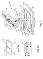
- FIG. 1is a three-dimensional view schematically illustrating a preferred embodiment of apparatus in accordance with the present invention for laser scribing grooves or vents in a sheet of chemically strengthened glass prior to separating the sheet into individual parts defined by the vents, the apparatus including a CO laser delivering a beam of radiation, optics for focusing the beam on a sheet of glass being scribed, a water spray atomizer for cooling the sheet in the vicinity of the focused laser beam, and a translation stage for translating the sheet relative to the focused beam and the water spray for forming one of the vents.
- a CO laserdelivering a beam of radiation
- opticsfor focusing the beam on a sheet of glass being scribed
- a water spray atomizerfor cooling the sheet in the vicinity of the focused laser beam
- a translation stagefor translating the sheet relative to the focused beam and the water spray for forming one of the vents.
- FIG. 1Ais a three-dimensional view schematically illustrating one form of a vent formed by the apparatus of FIG. 1 in the chemically strengthened glass sheet, relative to compressive-stress and tensile-stress zones of the sheet.
- FIG. 1Bis a three-dimensional view schematically further detail of the vent depicted in FIG. 1A .
- FIG. 2schematically illustrates scribing a glass sheet in accordance with the present invention using six vents to define four panels for subsequent separation, with each vent initiated at a corresponding purposefully created defect in the sheet.
- FIG. 3schematically illustrates coordinating movement of a round laser beam and the spray-cooling atomizer of FIG. 1 for forming an arc-shaped vent.
- FIG. 4schematically illustrates forming an arc-shaped vent using a round laser beam surrounded by an annular water-spray.
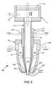
- FIG. 5is a cross-section view schematically illustrating an atomizer in accordance with the present invention for forming the annular water spray of FIG. 3 .
- FIG. 1schematically illustrates a preferred embodiment 10 of apparatus in accordance with the present invention for laser scribing grooves or vents in a sheet of chemically strengthened glass prior to separating the sheet into individual parts defined by the vents.
- the apparatusincludes a carbon monoxide (CO) laser 12 preferably operating in a continuous wave (CW) mode.
- COcarbon monoxide
- CWcontinuous wave
- Such a laseris commercially available from Coherent Inc. of Santa Clara, Calif., an assignee of the present invention.
- This laseris energized (driven) by radio frequency (RF) power.
- RFradio frequency
- the term “CW” as used herein for the CO laserincludes what might be designated quasi-CW operation resulting from the RF-driving, wherein the laser radiation is modulated at the frequency of the RF radiation. This frequency is typically about 100 megahertz (MHz).
- Beam 16can include CO characteristic laser-wavelengths in a range between about 4 micrometers ( ⁇ m) and about 6 ⁇ m. Beam 16 , on exiting window 14 , has an about round cross-section, and an about Gaussian intensity-distribution (indicated in the drawing by curve G). A more preferred cross-section for the beam has a more uniform intensity-distribution commonly referred as a “flat top” or “top-hat” intensity-distribution.
- a flat-top intensity distribution in apparatus(indicated in FIG. 1 by curve F) is provided by a simple inventive arrangement 18 , comprising a controlled-atmosphere tube 17 having windows 19 sealed to the tube at each end. Air having a controlled relative humidity is flowed through tube 17 via an inlet 20 and an outlet 22 . Passage through the humid air in the tube is sufficient to change the Gaussian energy distribution G of the beam entering the tube to the flat-top distribution F of the beam exiting the tube.
- tube 17has a length of about 25 centimeters (cm) and a diameter of about 5 cm.
- An input beamhad a 1/e 2 diameter of about 6 mm and a power of about 90W.
- Air having a relative humidity of about 35%was flowed through the tube at a rate of about 20 liters per minute (LPM). This was sufficient to provide the desired flat-top distribution.
- LPMliters per minute
- humidifying the airthis may be accomplished by any well-known means such as passing dry-air through a water bath. Relative humidity could be controlled by varying the air-flow rate through the water bath or the temperature of the water in the bath. As such humidifying means are well-known, a detailed description or depiction thereof is not presented herein.
- the remainder of the beam-path from the laser to the focusing lensesis enclosed, by one or a plurality of enclosures, indicated by long-dashed lines 27 for simplicity of illustration, and that the enclosure or enclosures are purged with a dried flowing gas, such as dry nitrogen.
- beam 16 having the flat-topped intensity-distributionis steered by plane-mirrors 24 and 26 to a beam focusing lens comprising spherical positive lens elements 28 and 30 .
- These elementsfocus beam 16 into a round focal-spot 34 on a sheet 38 of chemically-strengthened glass being scribed.
- Glass-sheet 38is supported on a translation stage 40 .
- Translating stage 40 in the direction indicated by arrow Ccauses focal-spot 34 to scan over sheet 38 linearly in the direction indicated by arrow D.
- the focal-spotmay be more generally referred to as the beam-spot. This is because in certain operations, described in detail further hereinbelow, the beam may be focused slightly above the surface of the sheet to create a beam-spot on the sheet having dimensions bigger than the actual (or theoretical) focal-spot.
- An atomizer 43is fed by water-flow through a conduit 44 , and by air-flow through a conduit 45 .
- the atomizersprays a water-mist 46 on the vent at some predetermined distance, for example about 2 mm, from the focal-spot.
- the cooling sprayeffectively “follows” the focal-spot over the sheet.
- the CO laser-radiation at the focal spotis absorbed in the bulk of glass and locally heats the glass to a depth determined by the beam and focal spot parameters.
- Near-immediate cooling by the water-mist sprayrapidly cools the heated glass and causes a controlled crack or vent 42 .
- the ventis actually initiated at a purposely-created defect (not shown) in the glass surface.
- the scale of the drawingdoes not permit accurate representation of the created defect.
- spherical lens 30is replaceable by a cylindrical (optical power in one transverse axis only) lens 32 .
- the poweris in a direction at 90° to the vent direction.
- Lens 30is moved out of the beam as indicated by arrow A.
- Lens 32is moved into the beam as indicated by arrow B.
- cylindrical lens 32has positive power only in the y-axis, which is the vent-width direction, as depicted. If the y-axis power of lens 32 is the same as the power of lens 30 an elongated (elliptical) focal-spot 36 (depicted in phantom) will result. Focal-spot 36 will have the same width (y-axis dimension) as focal-spot 34 , but will have a longer x-axis dimension due to the reduced optical power of the combination of lens elements 28 and 32 .
- lens 32could have a y-axis power different from that of lens 30 .
- lens 28may be made replaceable by another lens to provide for a wider variation of focal-spot dimensions.
- a particularly elongated focal spotcan be generated by replacing both spherical lenses with a single cylindrical lens having twice the y-axis power or two cylindrical lenses having the same Y-axis power as the two spherical lenses.
- the depth of vent 42 relative to the surface compressive zone of the chemically strengthened glassis very important. This is illustrated schematically in FIG. 1A and FIG. 1B .
- the upper and lower surface compressive regionsare designated 50 A and 50 B respectively.
- Region 52is the central tensile region between the compressive regions.
- the thickness of sheet 38is designated t; the depth of the compressive regions is designated d c ; the thickness of the central tensile region is designated t t and the depth of vent 42 is designated d v .
- the depthcan be conveniently controlled by controlling beam power focal-spot size, intensity distribution; the speed which the focal-spot is scanned over the chemically strengthened glass sheet; and the distance of the water-mist spray from the focal-spot.
- the ventmust have a depth (d v ) sufficient to extend through compressive region 50 A into tensile region 52 , but not so far into the tensile region that instability of the stress balance causes a self-propagating crack to develop.
- a sheetsuch as sheet 38
- the partscan then be separated by applying mechanic force to the vents, or introducing local thermal stress in the vents through heating the surface with a surface-absorbed laser beam, such as a CO 2 laser beam having a wavelength of about 10.6 ⁇ m.
- vents 42 A, 42 B, 42 C, 42 D, 42 E, and 42 FAll of the vents are formed by the same process. Accordingly the description of the process is provided only for one of the vents, arbitrarily selected as vent 42 B.
- the first stage of the processis creating a line-defect (linear defect) 60 from which the vent is initiated.
- Line defect 60is preferably formed in a direction transverse (perpendicular) to the direction in which the vent will be formed.
- a defectcould be created by a diamond scribe or the like but the highly compressively stressed surface region of the chemically strengthened glass makes for relatively poor control of the defect depth and a propensity for self-propagating surface cracking.
- the defectitself is laser-propagated from a directly-laser-damaged area 62 .
- the direct damageis formed by focusing the laser into a round spot quenched by the water-mist as described above. Beam parameters are selected such that that the damage is in the form of surface and sub-surface cracking, which is self-contained, i.e., not self-propagating.
- the laser beamwith a nominal wavelength of 5 ⁇ m had the flat-top intensity distribution discussed above, a diameter of about 12 mm as measured by burning a hole in a burn-card, and was focused on the surface of the sheet in a round spot having a diameter of 100 microns.
- the beam powerwas 80 Watts (W).
- the water-mist from the atomizerwas directed at a distance about 2 mm behind the round beam, with water-flow of 3 milliliters per minute (mL/min), and air-flow of 1.2 liters per minute (L/min).
- the water temperaturewas about 15° C.
- the scan speed of the laser beam (and water-mist spray)was about 250 mm per second (mm/sec).
- the length of the direct-damage regionwas about 6 mm.
- Line defect 60was created by propagating laser damage from the direct damage region 62 by scanning the laser beam and water-mist.
- the propagated damageis created by a similar process to the vent creation, i.e, by thermal-shock conditions resulting from the bulk laser-heating followed by the water-mist cooling.
- it is desirable that the depth of the propagated damage createddoes not extend into the central tensile region of the glass sufficient to cause one or more self-propagating cracks.
- the laser beamagain with a nominal wavelength of 5 ⁇ m, had the flat-top intensity distribution discussed above.
- a cylindrical lenswas arranged to focus the beam at a height of about 2 mm above the glass sheet with an elongated spot on the sheet having a width of about 0.4 mm and a length of about 12 mm as measured by the burn-card.
- the beam powerwas 80 Watts (W).
- the water-mist from the atomizerwas directed at a distance about 2 mm behind the elongated beam, and the water-mist parameters were as described above.
- the scan-speed of the laser beam (and water-mist spray)was about 200 mm per second (mm/sec).
- the length of defect 60was about 20 mm.
- the length of the beam spotwas in the scan direction
- the 5 ⁇ m-wavelength laser beamhad the flat-top intensity distribution discussed above.
- the cylindrical lenswas arranged to focus the beam at a height of about 5 mm above the glass sheet creating a beam with an elongated spot on the sheet having a width of about 0.8 mm and a length of about 12 mm, as measured by the burn-card.
- the beam power and water-mist parameterswere as described above.
- the vent-scanwas initiated with the beam behind the defect.
- the scan-speed of the laser beam (and water-mist spray)was about 180 mm per second (mm/sec), with the length of the elongated beam-spot in the scan direction.
- the depth of the ventis about the same as the depth of the defect.
- a particular benefit of the inventive vent-formation (contained-crack formation) methodis that it permits one vent to cross an existing vent without introducing any damage at the crossing point.
- the glass absorption coefficients in the wavelength region between about 4 micrometers ( ⁇ m) and about 6 ⁇ mallow for heating the glass, in bulk, to the controlled depth needed to extend below the surface compression region with minimal penetration into the central region, thereby maintaining the glass in a stable state.
- glass absorptionis almost zero. Even with sufficient power to cause heating, this heating would occur throughout the glass thickness and could not be effected at the controlled depth required of the inventive method.
- an elongated beamis used for generating vents 42 A-F. While the elongated beam is convenient for forming straight vents, it is not practical for forming a curved vent, as would be necessary for scribing a rounded rectangle shape. This is because alignment of the elongated beam and the water would mean that the beam was only in tangential contact with an arc to be scribed, and the beam and the water spray could not both be constantly on the arc.
- At least one popular smart-phone brandhas a cover glass in rounded rectangular form, so there is a motivation to adapt the inventive vent-scribing process to scribing arcs. This is facilitated by the fact that a round beam can be used to form a vent avoiding the tangential problem of the elongated beam. It is then only necessary to provide that the round beam and the water spray are always on the arc.
- FIG. 3One way of coordinating a round beam with the water spray for arc-scribing is depicted very schematically in FIG. 3 .
- an arrowhead tipped arcuate pathdepicts a vent-shape to be produced.
- An open circlerepresents a laser beam at various points on the arc. This could be effected by two-axis (x-y) movement of translation stage 40 in the apparatus of FIG. 1 .
- the water-mist sprayis depicted by a shaded circle. As the laser beam proceeds around the arcuate path, the water spray (the atomizer of FIG.
- FIG. 4An alternative method to providing arcuate shaped vents is schematically depicted in FIG. 4 .
- the water-mist sprayhas an annular shape (shaded annulus) disposed, preferably concentrically, around the laser beam (open circle) in a fixed spatial relationship thereto.
- a gassuch as nitrogen flowing coaxially around the laser beam and exiting through the same orifice as the beam provides positive pressure and prevents the water mist from impinging onto the glass in the region of laser heating.
- a minor drawback of this methodis that water mist is deposited ahead of the laser beam and the arcuate path. However, as this is deposited on not-yet-heated glass, no thermal shock results, and the deposited water is kept from interacting with the laser beam by the coaxial gas-pressure.
- this methodcan be implemented in the apparatus of FIG. 1 merely by changing the conventional atomizer by a specially configured atomizer. A detailed description of one such atomizer is set forth below with reference to FIG. 5 .
- an atomizer 70 in accordance with the present inventionincludes a central conduit 72 for air-flow and beam-transmission.
- Conduit 72is in fluid communication with an air plenum chamber 74 , which is enclosed at one end thereof by a window 76 , transparent to the CO laser-radiation wavelengths. The laser beam is introduced into the atomizer through this window as indicated in the drawing. Air is supplied to the plenum chamber via an aperture 78 therein.
- Conduit 72has a tapered region 72 A at the distal end thereof to force air-flow through the conduit into a jet.
- a water-sleeve 80Surrounding central conduit 72 is a water-sleeve 80 .
- Sleeve 80is sealed to conduit 72 near the proximal (input) end thereof and is open at the distal end.
- Sleeve 80is configured such that a cylindrical conduit is formed around the central conduit leaving an annular aperture 82 A at the open end of the cylindrical conduit.
- the sleeveis tapered corresponding to the taper of the central conduit such that the cylindrical conduit is also correspondingly tapered.
- Wateris input into the cylindrical conduit through input apertures 84 A and 84 B of sleeve 80 and exits the cylindrical conduit via aperture 82 A thereof. The juxtaposition of the water from aperture 82 A with the airflow from end 72 A of the central conduit creates the annular water mist spray of FIG. 4 .
- Vacuum sleeve 90Surrounding water sleeve 80 is a vacuum sleeve 90 .
- Vacuum sleeve 90is sealed to water sleeve 80 at a proximal end thereof and open at a distal end thereof.
- Sleeve 90is tapered in conformance with the tapering of central conduit 72 and water-sleeve 80 and forms a correspondingly tapered vacuum conduit 92 surrounding water sleeve 80 .
- Conduit 92has an annular opening 92 A surrounding annular water outlet 82 A of sleeve 80 .
- a vacuum pump(exhaust pump) communicates with conduit 92 via apertures 94 A and 94 B in vacuum sleeve 90 .
- Thisprovides for a vacuum or suction effect in an annular region surrounding the annular water-mist spray.
- One function of this vacuum or suction effectis to inhibit the incursion of the water mist spray into the region of the beam, reinforced by the air jet from the central conduit.
- Another functionis to remove any steam resulting from the interaction of the laser beam with pre-sprayed regions (by the annular spray) of a sheet being scribed.
Landscapes
- Physics & Mathematics (AREA)
- Optics & Photonics (AREA)
- Engineering & Computer Science (AREA)
- Chemical & Material Sciences (AREA)
- Plasma & Fusion (AREA)
- Mechanical Engineering (AREA)
- Materials Engineering (AREA)
- Organic Chemistry (AREA)
- Health & Medical Sciences (AREA)
- Toxicology (AREA)
- Thermal Sciences (AREA)
- Re-Forming, After-Treatment, Cutting And Transporting Of Glass Products (AREA)
Abstract
Description
Claims (21)
Priority Applications (1)
| Application Number | Priority Date | Filing Date | Title |
|---|---|---|---|
| US13/910,030US9328011B2 (en) | 2013-06-04 | 2013-06-04 | Laser-scribing of chemically strengthened glass |
Applications Claiming Priority (1)
| Application Number | Priority Date | Filing Date | Title |
|---|---|---|---|
| US13/910,030US9328011B2 (en) | 2013-06-04 | 2013-06-04 | Laser-scribing of chemically strengthened glass |
Publications (2)
| Publication Number | Publication Date |
|---|---|
| US20140352358A1 US20140352358A1 (en) | 2014-12-04 |
| US9328011B2true US9328011B2 (en) | 2016-05-03 |
Family
ID=51983588
Family Applications (1)
| Application Number | Title | Priority Date | Filing Date |
|---|---|---|---|
| US13/910,030Active2033-11-24US9328011B2 (en) | 2013-06-04 | 2013-06-04 | Laser-scribing of chemically strengthened glass |
Country Status (1)
| Country | Link |
|---|---|
| US (1) | US9328011B2 (en) |
Cited By (3)
| Publication number | Priority date | Publication date | Assignee | Title |
|---|---|---|---|---|
| US20150089977A1 (en)* | 2009-11-30 | 2015-04-02 | Corning Incorporated | Methods for laser scribing and separating glass substrates |
| US9896371B2 (en)* | 2012-06-12 | 2018-02-20 | Corning Precision Materials Co., Ltd. | Tempered glass cutting method and cutting apparatus |
| US20210153937A1 (en)* | 2017-08-25 | 2021-05-27 | Biolase, Inc. | Fractional handpiece system |
Families Citing this family (11)
| Publication number | Priority date | Publication date | Assignee | Title |
|---|---|---|---|---|
| US9328011B2 (en)* | 2013-06-04 | 2016-05-03 | Coherent, Inc. | Laser-scribing of chemically strengthened glass |
| US9260337B2 (en)* | 2014-01-09 | 2016-02-16 | Corning Incorporated | Methods and apparatus for free-shape cutting of flexible thin glass |
| JP6218646B2 (en)* | 2014-03-06 | 2017-10-25 | 株式会社ディスコ | Laser processing method |
| CN106573819A (en)* | 2014-08-20 | 2017-04-19 | 康宁股份有限公司 | Method and apparatus for producing high edge strength in cutting flexible thin glass |
| US9925620B2 (en) | 2015-08-19 | 2018-03-27 | Coherent, Inc. | Carbon monoxide laser machining system |
| US10423047B2 (en) | 2016-07-27 | 2019-09-24 | Coherent, Inc. | Laser machining method and apparatus |
| WO2018189296A1 (en) | 2017-04-12 | 2018-10-18 | Saint-Gobain Glass France | Electrochromic structure and method of separating electrochromic structure |
| TW202035321A (en)* | 2019-01-29 | 2020-10-01 | 美商康寧公司 | Methods and apparatus for free-form cutting of flexible thin glass |
| CN110465433B (en)* | 2019-08-06 | 2020-11-10 | 马鞍山市智新纳米材料有限公司 | Ceramic coating scraper coating spraying device |
| DE102020100051A1 (en)* | 2020-01-03 | 2021-07-08 | Schott Ag | Process for processing hard, brittle materials |
| US20240174544A1 (en)* | 2022-11-30 | 2024-05-30 | Corning Incorporated | Methods of laser cutting material |
Citations (29)
| Publication number | Priority date | Publication date | Assignee | Title |
|---|---|---|---|---|
| US3597578A (en)* | 1967-03-16 | 1971-08-03 | Nat Res Dev | Thermal cutting apparatus and method |
| US4403134A (en)* | 1981-03-17 | 1983-09-06 | Trumpf Gmbh & Co. | Method and apparatus for cutting by means of a laser beam |
| US4760583A (en)* | 1983-05-06 | 1988-07-26 | Coherent, Inc. | Laser delivery system |
| US6156049A (en)* | 1997-04-11 | 2000-12-05 | Coherent Inc. | Method and apparatus for transurethral resection of the prostate |
| US6576869B1 (en) | 1998-05-27 | 2003-06-10 | Excellon Automation Co. | Method and apparatus for drilling microvia holes in electrical circuit interconnection packages |
| US20070084839A1 (en)* | 2005-10-18 | 2007-04-19 | Wenwu Zhang | Thermal forming systems and active cooling processes |
| US20090032505A1 (en)* | 2007-07-31 | 2009-02-05 | National Applied Research Laboratories | Cutting device for cutting hard-brittle material |
| US20100206008A1 (en)* | 2009-02-19 | 2010-08-19 | Harvey Daniel R | Method of separating strengthened glass |
| US20100210442A1 (en)* | 2009-02-19 | 2010-08-19 | Anatoli Anatolyevich Abramov | Method of separating strengthened glass |
| US20100291353A1 (en)* | 2009-02-19 | 2010-11-18 | Matthew John Dejneka | Method of separating strengthened glass |
| US20110049765A1 (en)* | 2009-08-28 | 2011-03-03 | Xinghua Li | Methods for Laser Cutting Glass Substrates |
| US20110127242A1 (en)* | 2009-11-30 | 2011-06-02 | Xinghua Li | Methods for laser scribing and separating glass substrates |
| US20110226832A1 (en)* | 2010-03-19 | 2011-09-22 | John Frederick Bayne | Mechanical scoring and separation of strengthened glass |
| US20110248005A1 (en)* | 2008-09-12 | 2011-10-13 | L'air Liquide Societe Anonyme Pour L'etude Et L'exploitation Des Procedes Georges Claude | Laser Cutting Method and Equipment, with means for Modifying the Laser Beam Quality Factor by a Diffractive Optical Component |
| US20120047956A1 (en)* | 2010-08-31 | 2012-03-01 | Xinghua Li | Methods of separating strengthened glass substrates |
| US20120145331A1 (en)* | 2009-08-28 | 2012-06-14 | Kior, Inc, | Methods for laser cutting articles from ion exchanged glass substrates |
| WO2013031778A1 (en)* | 2011-08-31 | 2013-03-07 | 旭硝子株式会社 | Cutting method for reinforced glass plate and reinforced glass plate cutting device |
| US20130224433A1 (en)* | 2012-02-29 | 2013-08-29 | Electro Scientific Industries, Inc. | Method and apparatus for machining strengthened glass and articles produced thereby |
| US20130221053A1 (en)* | 2012-02-28 | 2013-08-29 | Electro Scientific Industries, Inc. | Method and apparatus for separation of strengthened glass and articles produced thereby |
| US20130224439A1 (en)* | 2012-02-28 | 2013-08-29 | Electro Scientific Industries, Inc. | Method and apparatus for separation of strengthened glass and articles produced thereby |
| US20130236666A1 (en)* | 2010-11-30 | 2013-09-12 | Corning Incorporated | Glass with surface and central regions under compression |
| US20130291598A1 (en)* | 2011-01-11 | 2013-11-07 | Asahi Glass Company, Limited | Method of cutting strengthened glass plate |
| US20130323469A1 (en)* | 2012-06-05 | 2013-12-05 | Corning Incorporated | Methods of cutting glass using a laser |
| US20140083986A1 (en)* | 2012-09-24 | 2014-03-27 | Electro Scientific Industries, Inc. | Method and apparatus for machining a workpiece |
| US20140093693A1 (en)* | 2012-02-28 | 2014-04-03 | Electro Scientific Industries, Inc. | Method and apparatus for separation of strengthened glass and articles produced thereby |
| US20140102146A1 (en)* | 2011-06-15 | 2014-04-17 | Asahi Glass Company, Limited | Method for cutting glass plate |
| US20140165652A1 (en)* | 2011-08-29 | 2014-06-19 | Asahi Glass Company, Limited | Cutting method for reinforced glass plate and reinforced glass plate cutting device |
| US20140340730A1 (en)* | 2013-03-15 | 2014-11-20 | Howard S. Bergh | Laser cutting strengthened glass |
| US20140352358A1 (en)* | 2013-06-04 | 2014-12-04 | Coherent, Inc. | Laser-scribing of chemically strengthened glass |
- 2013
- 2013-06-04USUS13/910,030patent/US9328011B2/enactiveActive
Patent Citations (30)
| Publication number | Priority date | Publication date | Assignee | Title |
|---|---|---|---|---|
| US3597578A (en)* | 1967-03-16 | 1971-08-03 | Nat Res Dev | Thermal cutting apparatus and method |
| US4403134A (en)* | 1981-03-17 | 1983-09-06 | Trumpf Gmbh & Co. | Method and apparatus for cutting by means of a laser beam |
| US4760583A (en)* | 1983-05-06 | 1988-07-26 | Coherent, Inc. | Laser delivery system |
| US6156049A (en)* | 1997-04-11 | 2000-12-05 | Coherent Inc. | Method and apparatus for transurethral resection of the prostate |
| US6576869B1 (en) | 1998-05-27 | 2003-06-10 | Excellon Automation Co. | Method and apparatus for drilling microvia holes in electrical circuit interconnection packages |
| US20070084839A1 (en)* | 2005-10-18 | 2007-04-19 | Wenwu Zhang | Thermal forming systems and active cooling processes |
| US20090032505A1 (en)* | 2007-07-31 | 2009-02-05 | National Applied Research Laboratories | Cutting device for cutting hard-brittle material |
| US20110248005A1 (en)* | 2008-09-12 | 2011-10-13 | L'air Liquide Societe Anonyme Pour L'etude Et L'exploitation Des Procedes Georges Claude | Laser Cutting Method and Equipment, with means for Modifying the Laser Beam Quality Factor by a Diffractive Optical Component |
| US20100206008A1 (en)* | 2009-02-19 | 2010-08-19 | Harvey Daniel R | Method of separating strengthened glass |
| US20100210442A1 (en)* | 2009-02-19 | 2010-08-19 | Anatoli Anatolyevich Abramov | Method of separating strengthened glass |
| US20100291353A1 (en)* | 2009-02-19 | 2010-11-18 | Matthew John Dejneka | Method of separating strengthened glass |
| US20110049765A1 (en)* | 2009-08-28 | 2011-03-03 | Xinghua Li | Methods for Laser Cutting Glass Substrates |
| US20120145331A1 (en)* | 2009-08-28 | 2012-06-14 | Kior, Inc, | Methods for laser cutting articles from ion exchanged glass substrates |
| US20110127242A1 (en)* | 2009-11-30 | 2011-06-02 | Xinghua Li | Methods for laser scribing and separating glass substrates |
| US20110226832A1 (en)* | 2010-03-19 | 2011-09-22 | John Frederick Bayne | Mechanical scoring and separation of strengthened glass |
| US20120047956A1 (en)* | 2010-08-31 | 2012-03-01 | Xinghua Li | Methods of separating strengthened glass substrates |
| US20130236666A1 (en)* | 2010-11-30 | 2013-09-12 | Corning Incorporated | Glass with surface and central regions under compression |
| US20130291598A1 (en)* | 2011-01-11 | 2013-11-07 | Asahi Glass Company, Limited | Method of cutting strengthened glass plate |
| US20140102146A1 (en)* | 2011-06-15 | 2014-04-17 | Asahi Glass Company, Limited | Method for cutting glass plate |
| US20140165652A1 (en)* | 2011-08-29 | 2014-06-19 | Asahi Glass Company, Limited | Cutting method for reinforced glass plate and reinforced glass plate cutting device |
| US20140174131A1 (en)* | 2011-08-31 | 2014-06-26 | Asahi Glass Company, Limited | Cutting method for reinforced glass plate and reinforced glass plate cutting device |
| WO2013031778A1 (en)* | 2011-08-31 | 2013-03-07 | 旭硝子株式会社 | Cutting method for reinforced glass plate and reinforced glass plate cutting device |
| US20130224439A1 (en)* | 2012-02-28 | 2013-08-29 | Electro Scientific Industries, Inc. | Method and apparatus for separation of strengthened glass and articles produced thereby |
| US20140093693A1 (en)* | 2012-02-28 | 2014-04-03 | Electro Scientific Industries, Inc. | Method and apparatus for separation of strengthened glass and articles produced thereby |
| US20130221053A1 (en)* | 2012-02-28 | 2013-08-29 | Electro Scientific Industries, Inc. | Method and apparatus for separation of strengthened glass and articles produced thereby |
| US20130224433A1 (en)* | 2012-02-29 | 2013-08-29 | Electro Scientific Industries, Inc. | Method and apparatus for machining strengthened glass and articles produced thereby |
| US20130323469A1 (en)* | 2012-06-05 | 2013-12-05 | Corning Incorporated | Methods of cutting glass using a laser |
| US20140083986A1 (en)* | 2012-09-24 | 2014-03-27 | Electro Scientific Industries, Inc. | Method and apparatus for machining a workpiece |
| US20140340730A1 (en)* | 2013-03-15 | 2014-11-20 | Howard S. Bergh | Laser cutting strengthened glass |
| US20140352358A1 (en)* | 2013-06-04 | 2014-12-04 | Coherent, Inc. | Laser-scribing of chemically strengthened glass |
Non-Patent Citations (1)
| Title |
|---|
| Sysoev et al., "Using of Middle IR Lasers for Guided Termocleavage of Glass", Fundamentals of Laser Assisted Micro- and Nanotechnologies, Proc. of SPIE, vol. 6985, 2008, pp. 69850O-1-69850O-11. |
Cited By (5)
| Publication number | Priority date | Publication date | Assignee | Title |
|---|---|---|---|---|
| US20150089977A1 (en)* | 2009-11-30 | 2015-04-02 | Corning Incorporated | Methods for laser scribing and separating glass substrates |
| US10358374B2 (en)* | 2009-11-30 | 2019-07-23 | Corning Incorporated | Methods for laser scribing and separating glass substrates |
| US9896371B2 (en)* | 2012-06-12 | 2018-02-20 | Corning Precision Materials Co., Ltd. | Tempered glass cutting method and cutting apparatus |
| US20210153937A1 (en)* | 2017-08-25 | 2021-05-27 | Biolase, Inc. | Fractional handpiece system |
| US12408982B2 (en)* | 2017-08-25 | 2025-09-09 | Biolase Mg Llc | Fractional handpiece system |
Also Published As
| Publication number | Publication date |
|---|---|
| US20140352358A1 (en) | 2014-12-04 |
Similar Documents
| Publication | Publication Date | Title |
|---|---|---|
| US9328011B2 (en) | Laser-scribing of chemically strengthened glass | |
| US20210122663A1 (en) | Apparatuses and methods for synchronous multi-laser processing of transparent workpieces | |
| KR100510775B1 (en) | Method and device for rapid cutting of a workpiece made from a brittle material by means of laser beams | |
| JP5976906B2 (en) | Laser scribing and separation method for glass substrate | |
| KR101329477B1 (en) | Method and Apparatus for Scoring and Separating a Brittle Material with a Single Beam of Radiation | |
| CN100515651C (en) | Method and apparatus for scribing brittle materials | |
| KR100876502B1 (en) | Substrate cutting device using microwave laser beam and cutting method | |
| TWI415811B (en) | Method for separating a sheet of brittle material | |
| JP5539625B2 (en) | Laser processing method | |
| US8109118B2 (en) | Method for removing bubbles from molten glass and process for producing glass | |
| US20080143021A1 (en) | Method For Finely Polishing/Structuring Thermosensitive Dielectric Materials By A Laser Beam | |
| US20060021977A1 (en) | Process and apparatus for scoring a brittle material incorporating moving optical assembly | |
| US11904410B2 (en) | Laser surface preparation of coated substrate | |
| US20110127244A1 (en) | Methods for laser scribing and separating glass substrates | |
| CN103170744A (en) | Laser welding device and welding method | |
| CN103182603A (en) | Laser scanning processing device | |
| JP2009255114A (en) | Brittle material substrate processing apparatus and brittle material substrate cutting method | |
| KR101483746B1 (en) | Laser glass cutting system and method for cutting glass using the same | |
| WO2013094059A1 (en) | Method for fracturing brittle material substrate | |
| KR102652103B1 (en) | Method of manufacturing a cover glass | |
| KR102375189B1 (en) | Glass tube cutting method and apparatus using gas torch and laser | |
| KR20100008048A (en) | Laser cutting method | |
| KR100659931B1 (en) | Substrate cutting device using laser and method | |
| CN115043586A (en) | Laser cutting method for improving quality of cut surface of glass carrier plate | |
| JP2012006320A (en) | Method for cutting brittle material substrate |
Legal Events
| Date | Code | Title | Description |
|---|---|---|---|
| AS | Assignment | Owner name:COHERENT, INC., CALIFORNIA Free format text:ASSIGNMENT OF ASSIGNORS INTEREST;ASSIGNORS:WASHKO, JOHN F., JR.;LI, XINGHUA;BOSENBERG, WALTER R.;SIGNING DATES FROM 20130611 TO 20130618;REEL/FRAME:031419/0424 | |
| STCF | Information on status: patent grant | Free format text:PATENTED CASE | |
| AS | Assignment | Owner name:BARCLAYS BANK PLC, AS COLLATERAL AGENT, NEW YORK Free format text:NOTICE OF GRANT OF SECURITY INTEREST IN PATENTS;ASSIGNOR:COHERENT, INC.;REEL/FRAME:040575/0001 Effective date:20161107 | |
| MAFP | Maintenance fee payment | Free format text:PAYMENT OF MAINTENANCE FEE, 4TH YEAR, LARGE ENTITY (ORIGINAL EVENT CODE: M1551); ENTITY STATUS OF PATENT OWNER: LARGE ENTITY Year of fee payment:4 | |
| AS | Assignment | Owner name:JPMORGAN CHASE BANK, N.A., AS COLLATERAL AGENT, NEW YORK Free format text:SECURITY INTEREST;ASSIGNORS:II-VI INCORPORATED;II-VI DELAWARE, INC.;M CUBED TECHNOLOGIES, INC.;AND OTHERS;REEL/FRAME:060562/0254 Effective date:20220701 Owner name:COHERENT, INC., CALIFORNIA Free format text:PATENT RELEASE AND REASSIGNMENT - RELEASE OF REEL/FRAME 040575/0001;ASSIGNOR:BARCLAYS BANK PLC, AS COLLATERAL AGENT;REEL/FRAME:060562/0650 Effective date:20220701 | |
| MAFP | Maintenance fee payment | Free format text:PAYMENT OF MAINTENANCE FEE, 8TH YEAR, LARGE ENTITY (ORIGINAL EVENT CODE: M1552); ENTITY STATUS OF PATENT OWNER: LARGE ENTITY Year of fee payment:8 |