US9327570B2 - Ball joint assembly for a control arm - Google Patents
Ball joint assembly for a control armDownload PDFInfo
- Publication number
- US9327570B2 US9327570B2US14/580,572US201414580572AUS9327570B2US 9327570 B2US9327570 B2US 9327570B2US 201414580572 AUS201414580572 AUS 201414580572AUS 9327570 B2US9327570 B2US 9327570B2
- Authority
- US
- United States
- Prior art keywords
- stud
- bearing
- ball
- shaped portion
- housing
- Prior art date
- Legal status (The legal status is an assumption and is not a legal conclusion. Google has not performed a legal analysis and makes no representation as to the accuracy of the status listed.)
- Active
Links
Images


Classifications
- B—PERFORMING OPERATIONS; TRANSPORTING
- B60—VEHICLES IN GENERAL
- B60G—VEHICLE SUSPENSION ARRANGEMENTS
- B60G7/00—Pivoted suspension arms; Accessories thereof
- B60G7/005—Ball joints
- B—PERFORMING OPERATIONS; TRANSPORTING
- B60—VEHICLES IN GENERAL
- B60G—VEHICLE SUSPENSION ARRANGEMENTS
- B60G7/00—Pivoted suspension arms; Accessories thereof
- B60G7/02—Attaching arms to sprung part of vehicle
- F—MECHANICAL ENGINEERING; LIGHTING; HEATING; WEAPONS; BLASTING
- F16—ENGINEERING ELEMENTS AND UNITS; GENERAL MEASURES FOR PRODUCING AND MAINTAINING EFFECTIVE FUNCTIONING OF MACHINES OR INSTALLATIONS; THERMAL INSULATION IN GENERAL
- F16C—SHAFTS; FLEXIBLE SHAFTS; ELEMENTS OR CRANKSHAFT MECHANISMS; ROTARY BODIES OTHER THAN GEARING ELEMENTS; BEARINGS
- F16C11/00—Pivots; Pivotal connections
- F16C11/04—Pivotal connections
- F16C11/045—Pivotal connections with at least a pair of arms pivoting relatively to at least one other arm, all arms being mounted on one pin
- F—MECHANICAL ENGINEERING; LIGHTING; HEATING; WEAPONS; BLASTING
- F16—ENGINEERING ELEMENTS AND UNITS; GENERAL MEASURES FOR PRODUCING AND MAINTAINING EFFECTIVE FUNCTIONING OF MACHINES OR INSTALLATIONS; THERMAL INSULATION IN GENERAL
- F16C—SHAFTS; FLEXIBLE SHAFTS; ELEMENTS OR CRANKSHAFT MECHANISMS; ROTARY BODIES OTHER THAN GEARING ELEMENTS; BEARINGS
- F16C11/00—Pivots; Pivotal connections
- F16C11/04—Pivotal connections
- F16C11/06—Ball-joints; Other joints having more than one degree of angular freedom, i.e. universal joints
- F16C11/0604—Construction of the male part
- F—MECHANICAL ENGINEERING; LIGHTING; HEATING; WEAPONS; BLASTING
- F16—ENGINEERING ELEMENTS AND UNITS; GENERAL MEASURES FOR PRODUCING AND MAINTAINING EFFECTIVE FUNCTIONING OF MACHINES OR INSTALLATIONS; THERMAL INSULATION IN GENERAL
- F16C—SHAFTS; FLEXIBLE SHAFTS; ELEMENTS OR CRANKSHAFT MECHANISMS; ROTARY BODIES OTHER THAN GEARING ELEMENTS; BEARINGS
- F16C11/00—Pivots; Pivotal connections
- F16C11/04—Pivotal connections
- F16C11/06—Ball-joints; Other joints having more than one degree of angular freedom, i.e. universal joints
- F16C11/0614—Ball-joints; Other joints having more than one degree of angular freedom, i.e. universal joints the female part of the joint being open on two sides
- F—MECHANICAL ENGINEERING; LIGHTING; HEATING; WEAPONS; BLASTING
- F16—ENGINEERING ELEMENTS AND UNITS; GENERAL MEASURES FOR PRODUCING AND MAINTAINING EFFECTIVE FUNCTIONING OF MACHINES OR INSTALLATIONS; THERMAL INSULATION IN GENERAL
- F16C—SHAFTS; FLEXIBLE SHAFTS; ELEMENTS OR CRANKSHAFT MECHANISMS; ROTARY BODIES OTHER THAN GEARING ELEMENTS; BEARINGS
- F16C11/00—Pivots; Pivotal connections
- F16C11/04—Pivotal connections
- F16C11/06—Ball-joints; Other joints having more than one degree of angular freedom, i.e. universal joints
- F16C11/0619—Ball-joints; Other joints having more than one degree of angular freedom, i.e. universal joints the female part comprising a blind socket receiving the male part
- F—MECHANICAL ENGINEERING; LIGHTING; HEATING; WEAPONS; BLASTING
- F16—ENGINEERING ELEMENTS AND UNITS; GENERAL MEASURES FOR PRODUCING AND MAINTAINING EFFECTIVE FUNCTIONING OF MACHINES OR INSTALLATIONS; THERMAL INSULATION IN GENERAL
- F16C—SHAFTS; FLEXIBLE SHAFTS; ELEMENTS OR CRANKSHAFT MECHANISMS; ROTARY BODIES OTHER THAN GEARING ELEMENTS; BEARINGS
- F16C11/00—Pivots; Pivotal connections
- F16C11/04—Pivotal connections
- F16C11/06—Ball-joints; Other joints having more than one degree of angular freedom, i.e. universal joints
- F16C11/0666—Sealing means between the socket and the inner member shaft
- F16C11/0671—Sealing means between the socket and the inner member shaft allowing operative relative movement of joint parts due to flexing of the sealing means
- F—MECHANICAL ENGINEERING; LIGHTING; HEATING; WEAPONS; BLASTING
- F16—ENGINEERING ELEMENTS AND UNITS; GENERAL MEASURES FOR PRODUCING AND MAINTAINING EFFECTIVE FUNCTIONING OF MACHINES OR INSTALLATIONS; THERMAL INSULATION IN GENERAL
- F16C—SHAFTS; FLEXIBLE SHAFTS; ELEMENTS OR CRANKSHAFT MECHANISMS; ROTARY BODIES OTHER THAN GEARING ELEMENTS; BEARINGS
- F16C11/00—Pivots; Pivotal connections
- F16C11/04—Pivotal connections
- F16C11/06—Ball-joints; Other joints having more than one degree of angular freedom, i.e. universal joints
- F16C11/0685—Manufacture of ball-joints and parts thereof, e.g. assembly of ball-joints
- F—MECHANICAL ENGINEERING; LIGHTING; HEATING; WEAPONS; BLASTING
- F16—ENGINEERING ELEMENTS AND UNITS; GENERAL MEASURES FOR PRODUCING AND MAINTAINING EFFECTIVE FUNCTIONING OF MACHINES OR INSTALLATIONS; THERMAL INSULATION IN GENERAL
- F16C—SHAFTS; FLEXIBLE SHAFTS; ELEMENTS OR CRANKSHAFT MECHANISMS; ROTARY BODIES OTHER THAN GEARING ELEMENTS; BEARINGS
- F16C23/00—Bearings for exclusively rotary movement adjustable for aligning or positioning
- F16C23/02—Sliding-contact bearings
- F16C23/04—Sliding-contact bearings self-adjusting
- F16C23/043—Sliding-contact bearings self-adjusting with spherical surfaces, e.g. spherical plain bearings
- F16C23/045—Sliding-contact bearings self-adjusting with spherical surfaces, e.g. spherical plain bearings for radial load mainly, e.g. radial spherical plain bearings
- B—PERFORMING OPERATIONS; TRANSPORTING
- B60—VEHICLES IN GENERAL
- B60G—VEHICLE SUSPENSION ARRANGEMENTS
- B60G2200/00—Indexing codes relating to suspension types
- B60G2200/10—Independent suspensions
- B60G2200/14—Independent suspensions with lateral arms
- B60G2200/142—Independent suspensions with lateral arms with a single lateral arm, e.g. MacPherson type
- B60G2200/1424—Independent suspensions with lateral arms with a single lateral arm, e.g. MacPherson type the lateral arm having an L-shape
- B—PERFORMING OPERATIONS; TRANSPORTING
- B60—VEHICLES IN GENERAL
- B60G—VEHICLE SUSPENSION ARRANGEMENTS
- B60G2204/00—Indexing codes related to suspensions per se or to auxiliary parts
- B60G2204/10—Mounting of suspension elements
- B60G2204/14—Mounting of suspension arms
- B60G2204/143—Mounting of suspension arms on the vehicle body or chassis
- B60G2204/1431—Mounting of suspension arms on the vehicle body or chassis of an L-shaped arm
- B—PERFORMING OPERATIONS; TRANSPORTING
- B60—VEHICLES IN GENERAL
- B60G—VEHICLE SUSPENSION ARRANGEMENTS
- B60G2204/00—Indexing codes related to suspensions per se or to auxiliary parts
- B60G2204/40—Auxiliary suspension parts; Adjustment of suspensions
- B60G2204/416—Ball or spherical joints
- B—PERFORMING OPERATIONS; TRANSPORTING
- B60—VEHICLES IN GENERAL
- B60G—VEHICLE SUSPENSION ARRANGEMENTS
- B60G2206/00—Indexing codes related to the manufacturing of suspensions: constructional features, the materials used, procedures or tools
- B60G2206/01—Constructional features of suspension elements, e.g. arms, dampers, springs
- B60G2206/90—Maintenance
- B60G2206/91—Assembly procedures
- F—MECHANICAL ENGINEERING; LIGHTING; HEATING; WEAPONS; BLASTING
- F16—ENGINEERING ELEMENTS AND UNITS; GENERAL MEASURES FOR PRODUCING AND MAINTAINING EFFECTIVE FUNCTIONING OF MACHINES OR INSTALLATIONS; THERMAL INSULATION IN GENERAL
- F16C—SHAFTS; FLEXIBLE SHAFTS; ELEMENTS OR CRANKSHAFT MECHANISMS; ROTARY BODIES OTHER THAN GEARING ELEMENTS; BEARINGS
- F16C11/00—Pivots; Pivotal connections
- F16C11/04—Pivotal connections
- F16C11/06—Ball-joints; Other joints having more than one degree of angular freedom, i.e. universal joints
- F16C11/08—Ball-joints; Other joints having more than one degree of angular freedom, i.e. universal joints with resilient bearings
- F16C11/083—Ball-joints; Other joints having more than one degree of angular freedom, i.e. universal joints with resilient bearings by means of parts of rubber or like materials
- F—MECHANICAL ENGINEERING; LIGHTING; HEATING; WEAPONS; BLASTING
- F16—ENGINEERING ELEMENTS AND UNITS; GENERAL MEASURES FOR PRODUCING AND MAINTAINING EFFECTIVE FUNCTIONING OF MACHINES OR INSTALLATIONS; THERMAL INSULATION IN GENERAL
- F16C—SHAFTS; FLEXIBLE SHAFTS; ELEMENTS OR CRANKSHAFT MECHANISMS; ROTARY BODIES OTHER THAN GEARING ELEMENTS; BEARINGS
- F16C2226/00—Joining parts; Fastening; Assembling or mounting parts
- F16C2226/50—Positive connections
- F16C2226/70—Positive connections with complementary interlocking parts
- F16C2226/76—Positive connections with complementary interlocking parts with tongue and groove or key and slot
- F—MECHANICAL ENGINEERING; LIGHTING; HEATING; WEAPONS; BLASTING
- F16—ENGINEERING ELEMENTS AND UNITS; GENERAL MEASURES FOR PRODUCING AND MAINTAINING EFFECTIVE FUNCTIONING OF MACHINES OR INSTALLATIONS; THERMAL INSULATION IN GENERAL
- F16C—SHAFTS; FLEXIBLE SHAFTS; ELEMENTS OR CRANKSHAFT MECHANISMS; ROTARY BODIES OTHER THAN GEARING ELEMENTS; BEARINGS
- F16C2326/00—Articles relating to transporting
- F16C2326/01—Parts of vehicles in general
- F16C2326/05—Vehicle suspensions, e.g. bearings, pivots or connecting rods used therein
- Y—GENERAL TAGGING OF NEW TECHNOLOGICAL DEVELOPMENTS; GENERAL TAGGING OF CROSS-SECTIONAL TECHNOLOGIES SPANNING OVER SEVERAL SECTIONS OF THE IPC; TECHNICAL SUBJECTS COVERED BY FORMER USPC CROSS-REFERENCE ART COLLECTIONS [XRACs] AND DIGESTS
- Y10—TECHNICAL SUBJECTS COVERED BY FORMER USPC
- Y10T—TECHNICAL SUBJECTS COVERED BY FORMER US CLASSIFICATION
- Y10T29/00—Metal working
- Y10T29/49—Method of mechanical manufacture
- Y10T29/49636—Process for making bearing or component thereof
- Y10T29/49643—Rotary bearing
- Y10T29/49647—Plain bearing
- Y10T29/49648—Self-adjusting or self-aligning, including ball and socket type, bearing and component making
Definitions
- the present inventionis related generally to bushing assemblies and more particularly to metal bushing assemblies having a stud and a housing which is rotatable relative to the stud.
- MacPherson strut systemstypically include a lower control arm (also referred to as an A-arm) which pivots relative to the vehicle's frame to allow a wheel and tire to move upwardly and downwardly relative to the frame during cornering or in response to encountering an object, such as a pot hole in the road.
- A-armlower control arm
- a lower control arm 10 for a Macpherson strut type of suspension systemis generally shown in FIG. 1 .
- the lower control arm 10includes a ball joint 11 for connection with a steering knuckle (not shown) of a hub assembly and a pair of bushings 12 , 13 for guiding the pivoting movement of the lower control arm 10 relative to the vehicle's frame (not shown).
- One of the bushingsis a horizontal bushing 12 which is configured to pivot relative to the vehicle frame about longitudinally extending bolt (not shown).
- the other bushing 13is a vertical bushing which is configured to pivot relative to the vehicle frame about a vertically extending bolt (not shown).
- an conventional vertical bushing 13is generally shown. As best shown in FIG. 2C , the conventional vertical bushing 13 has an outer metallic sleeve 14 , which is press fit into an opening in the lower control arm 10 (shown in FIG. 1 ), a rubber cushion 15 and an inner metallic sleeve 16 .
- the rubber cushion 15extends radially between and interconnects the outer and inner metallic sleeves 14 , 16 .
- the inner metallic sleeve 16pivots or twists relative to the outer metallic sleeve 14 during movement of the vehicle suspension, such as when the vehicle encounters a pot hole in the road.
- the rubber cushion 15deforms elastically to allow the pivoting movement between these sleeves 14 , 16 and absorbs/deforms due to a radial load. As such, during operation of the vehicle, the rubber cushion 15 is exposed to both a radial load and a twisting load motion. Exposure to the radial load and twisting motion leads to deterioration in the rubber cushion 15 , thereby reducing the life of the vertical bushing 13 .
- the ball joint assemblyincludes a housing which is adapted for receipt within an opening of the control arm.
- the ball joint assemblyfurther includes a bearing which has an inner surface that extends between open first and second ends and which presents a curved bearing surface that surrounds a generally spherically-shaped cavity.
- a studis provided which has an outer surface with a generally ball-shaped portion that has at least two curved surfaces and at least two recessed surfaces.
- the bearingfurther includes a passage with a pair of slots that extend from one of the open ends of the bearing to the spherically-shaped cavity.
- the generally ball-shaped portion of the studis insertable into the spherically-shaped cavity of the bearing by aligning the curved surfaces of the stud with the slots of the passage.
- the studis rotatable while the ball-shaped portion of the stud is positioned within the spherically-shaped cavity of the bearing to establish slidable contact between the curved surfaces of the stud and the curved bearing surface of the bearing to allow pivoting of the stud relative to the bearing.
- the improved ball joint assemblyexhibits reduced wear and thus has an improved operating life as compared to the vertical bushing assemblies that are typically found in such control arms. Additionally, the ball joint assembly can be manufactured at low cost and can be sold as an aftermarket part as a replacement for worn bushings.
- the methodincludes the step of preparing a housing and a bearing.
- the bearinghas a curved bearing surface that surrounds a generally spherically shaped cavity and has a passage with two slots that extend from an end of the bearing to the spherically shaped cavity.
- the methodproceeds with the step of preparing a stud that includes a generally ball-shaped portion that has at least two curved surfaces and at least two recessed surfaces.
- the methodcontinues with the step of aligning the curved surfaces of the ball-shaped portion of the stud with the slots of the passage of the bearing.
- the methodproceeds with the step of guiding the ball shaped portion of the stud into the spherically shaped cavity of the bearing.
- the methodcontinues with the step of guiding the ball shaped portion of the stud into the spherically shaped cavity of the bearing.
- the methodproceeds with the step of rotating the stud relative to the bearing to establish slidable contact between the curved surfaces of the ball-shaped portion with the bearing surface of the bearing to allow pivoting of the stud relative to the bearing.
- FIG. 1is a perspective view of one known control arm assembly
- FIG. 2Ais a front elevation view of an exemplary vertical bushing from the control arm of FIG. 1 ;
- FIG. 2Bis a top elevation view of the vertical bushing of FIG. 2A ;
- FIG. 2Cis a cross-sectional view of the vertical bushing of FIGS. 2A and 2B and taken along Line C-C of FIG. 2B ;
- FIG. 3is a perspective view of an exemplary embodiment of an improved control arm assembly
- FIG. 4is a cross-sectional view of the control arm assembly of FIG. 3 and connected with a vehicle frame;
- FIG. 5is another cross-sectional view of the control arm assembly of FIG. 3 connected with a vehicle frame and in a different rotational position than FIG. 4 ;
- FIG. 6is yet another cross-sectional view of the control arm assembly of FIG. 3 connected with a vehicle frame and in a different rotational position than FIGS. 4 and 5 ;
- FIG. 7is a cross-sectional and exploded view of an exemplary embodiment of an improved ball joint assembly of the control arm of FIG. 3 ;
- FIG. 8is a cross-sectional view of the ball joint assembly of FIG. 7 ;
- FIG. 9is a front elevation view of an exemplary embodiment of a stud of the ball joint assembly of FIG. 7 ;
- FIG. 10is a top elevation view of the stud of FIG. 9 ;
- FIG. 11is a cross-sectional view of the stud of FIG. 9 and taken along Line 11 - 11 of FIG. 10 ;
- FIG. 12is a perspective view of the stud of FIG. 9 ;
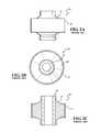
- FIG. 13is a cross-sectional view of a housing of the ball joint assembly of FIG. 7 ;
- FIG. 14is another cross-sectional view of the housing of the ball joint assembly of FIG. 7 and taken from a different perspective than FIG. 13 ;
- FIG. 15is a top elevation view of the housing of FIG. 13 ;
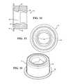
- FIG. 16is a perspective view of the housing of FIG. 13 .
- the control arm assembly 20includes a body 22 and a ball socket assembly 24 for attachment with a steering knuckle (not shown) of a vehicle.
- the control arm assembly 20further includes a ball joint assembly 26 and a horizontal bushing 28 which are configured to join the control arm body 22 with a vehicle frame 30 (shown in FIGS. 6-8 ).
- the ball joint assembly 26allows the control arm body 22 to pivot relative to the vehicle frame 30 during operation of the vehicle, for example, in response to a wheel on the vehicle encountering an obstacle such as a pothole or in response to the vehicle rolling while cornering at high speeds.
- the ball joint assembly 26includes a stud 32 which is fixed to the vehicle frame 30 with a fastener and a housing 34 which is engaged with the control arm body 22 and which is pivotable relative to the stud 32 .
- the fastener which fixes the stud 32 with the vehicle frame 30is a bolt 36 .
- any suitable type of fastener or connecting meansmay be employed.
- the housing 34 of the exemplary embodimenthas an exterior surface 38 which extends along an axis A and is shaped and sized to be press-fit into an opening of the control arm body 22 .
- One axial end of the exterior surface 38includes a radially outwardly extending flange 40 .
- the flange 40defines a stopping point to ensure that the ball joint assembly 26 is properly installed in the opening of the control arm body 22 .
- the housing 34is preferably made of one integral piece of metal, such as steel.
- the ball joint assembly 26further includes a bearing 42 which establishes the pivoting relationship between the housing 34 and the stud 32 .
- the bearing 42 and the housing 34are formed as one integral piece of metal.
- the bearing 42 and the housing 34could alternately be constructed as separate elements which are formed separately and are subsequently joined together.
- the bearing 42has an inner surface which extends axially between opposite open first and second ends. A portion of the inner surface defines a curved bearing surface 44 , which is curved with a generally constant diameter to present a generally spherically-shaped cavity (hereinafter referred to as the “spherical cavity 48 ”). As such, the curved bearing surface 44 is generally semi-spherically shaped or curved.
- the stud 32is formed of one integral piece of material and extends through the bearing 42 past the opposite open ends.
- the stud 32has a through passage 50 for receiving the bolt 36 to attach the stud 32 with the vehicle frame 30 .
- the stud 32has a generally ball-shaped portion (hereinafter referred to as the “ball portion 52 ”) and a pair of end portions 54 .
- the ball portion 52 of the stud 32has a pair of curved surfaces 55 and a pair of recessed surfaces 56 .
- the curved surfaces 44are generally semi-spherical in shape in that they have a generally constant diameter which is similar to the diameter of the generally spherical cavity 48 of the bearing 42 (shown in FIGS. 13 and 14 ), and the recessed surfaces 56 are recessed relative to the diameter of the curved surfaces 44 . That is, the curved surfaces 44 extend radially further from a central point in the ball portion 52 than the recessed surfaces 56 .
- the curved surfaces 44are diametrically opposite of one another, and the recessed surfaces 56 are diametrically opposite of one another.
- the recessed surfaces 56 of the ball portion 52are generally flat in shape. However, it should be appreciated that the recessed surfaces 56 could take a range of different shapes.
- the diameter of the curved surfaces 44 of the ball portion 52 of the stud 32is similar to the diameter of the spherical cavity 48 (shown in FIGS. 13 and 14 ) of the bearing 42 to allow, thus allowing for sliding contact between the curved surfaces 44 of the stud 32 and the bearing surface 46 of the bearing 42 .
- the ball portion 52 of the stud 32is captured by the bearing surface 46 on both sides of an equator of the ball portion 52 . That is, the single bearing 42 with the single bearing surface 46 supports both an upper hemisphere and a lower hemisphere of the ball portion 52 . This enables the relative pivoting or rotation of the housing 34 relative to the stud 32 shown in FIGS. 4-6 .
- a lubricant(not shown), such as grease, is preferably employed to provide a low friction interface between the curved surfaces 44 of the stud 32 and the bearing surface 46 of the bearing 42 .
- the bearing 42includes a passage which is shaped for guiding the ball portion 52 (shown in FIGS. 8-11 ) of the stud 32 into the spherical cavity 48 of the bearing 42 .
- the passageextends axially from one of the open ends of the bearing 42 to the shaped cavity.
- the passageis defined by a pair of slots 58 which extend to one of the open ends of the bearing 42 .
- the passage in the bearing 42is generally oval in shape with a pair of long sides and a pair of curved sides.
- the ball joint assembly 26further includes a pair of dust boots 60 which establish fluid-tight seals between the housing 34 and the stud 32 to hold the lubricant within the ball joint assembly 26 and also to protect the internal components of the ball joint assembly 26 from external debris.
- the dust boots 60may be engaged with the stud 32 and the housing 34 through any suitable connection means.
- Assembly of the ball joint assembly 26includes separately forming the housing 34 with the integrally connected bearing 42 and the stud 32 .
- the stud 32is then oriented such that the curved surfaces 44 of the ball portion 52 are aligned with the slots 58 of the passage 50 , and the ball portion 52 is inserted axially into the spherical cavity 48 of the bearing 42 .
- the stud 32is rotated by relative to the housing 34 , for example, by ninety degrees 90°) to slidably engage the curved surfaces 55 of the ball portion 52 with the bearing surface 44 of the bearing 42 .
- the dust boots 60are engaged with the housing 34 and stud 32 to protect the interior of the ball joint assembly 20 . This process is less laborious and less costly than the processes of assembling other known bushing assemblies.
Landscapes
- Engineering & Computer Science (AREA)
- General Engineering & Computer Science (AREA)
- Mechanical Engineering (AREA)
- Pivots And Pivotal Connections (AREA)
- Vehicle Body Suspensions (AREA)
Abstract
Description
Claims (13)
Priority Applications (2)
| Application Number | Priority Date | Filing Date | Title |
|---|---|---|---|
| US14/580,572US9327570B2 (en) | 2014-03-04 | 2014-12-23 | Ball joint assembly for a control arm |
| PCT/US2014/072076WO2015134093A1 (en) | 2014-03-04 | 2014-12-23 | Ball joint assembly for a control arm |
Applications Claiming Priority (2)
| Application Number | Priority Date | Filing Date | Title |
|---|---|---|---|
| US201461947760P | 2014-03-04 | 2014-03-04 | |
| US14/580,572US9327570B2 (en) | 2014-03-04 | 2014-12-23 | Ball joint assembly for a control arm |
Publications (2)
| Publication Number | Publication Date |
|---|---|
| US20150251511A1 US20150251511A1 (en) | 2015-09-10 |
| US9327570B2true US9327570B2 (en) | 2016-05-03 |
Family
ID=54016549
Family Applications (1)
| Application Number | Title | Priority Date | Filing Date |
|---|---|---|---|
| US14/580,572ActiveUS9327570B2 (en) | 2014-03-04 | 2014-12-23 | Ball joint assembly for a control arm |
Country Status (2)
| Country | Link |
|---|---|
| US (1) | US9327570B2 (en) |
| WO (1) | WO2015134093A1 (en) |
Cited By (7)
| Publication number | Priority date | Publication date | Assignee | Title |
|---|---|---|---|---|
| USD785513S1 (en)* | 2015-03-31 | 2017-05-02 | Austem Co., Ltd. | Lower arm for vehicle suspension system |
| US20170335884A1 (en)* | 2016-05-23 | 2017-11-23 | United Technologies Corporation | Spherical bearing sleeve configured with one or more discrete collars |
| USD821931S1 (en)* | 2016-10-24 | 2018-07-03 | Mevotech Lp | Outer tie rod end |
| US20190017541A1 (en)* | 2017-07-13 | 2019-01-17 | Federal-Mogul Motorparts Llc | Vertical control arm bushing with dust boot having strengthening portions |
| US10570950B2 (en) | 2016-05-23 | 2020-02-25 | United Technologies Corporation | Spherical joint assembly with a spherical bearing between integral collars |
| US12122211B1 (en) | 2023-06-27 | 2024-10-22 | RB Distribution, Inc. | Adjustable control arm and ball joint assembly |
| US12187093B1 (en) | 2023-06-27 | 2025-01-07 | RB Distribution, Inc. | Control arm and adjustable ball joint |
Families Citing this family (3)
| Publication number | Priority date | Publication date | Assignee | Title |
|---|---|---|---|---|
| WO2017115932A1 (en)* | 2015-12-30 | 2017-07-06 | 주식회사 일진 | Hybrid suspension arm for vehicle and manufacturing method therefor |
| DE102021109529A1 (en)* | 2021-04-15 | 2022-10-20 | Airbus Operations Gmbh | Articulation and method for movably coupling a first component to a second component |
| USD1012789S1 (en)* | 2021-05-13 | 2024-01-30 | Toyota Motor Engineering & Manufacturing North America, Inc. | Single piece upper control arm |
Citations (42)
| Publication number | Priority date | Publication date | Assignee | Title |
|---|---|---|---|---|
| US1062197A (en) | 1909-08-19 | 1913-05-20 | Oscar Stegeman | Bearing for supporting radiators in automobile-frames. |
| US1065483A (en) | 1912-03-11 | 1913-06-24 | Harry C Turner | Ball-and-socket joint. |
| US2047885A (en) | 1933-02-08 | 1936-07-14 | Riebe August | Journal bearing |
| US2309281A (en) | 1942-01-27 | 1943-01-26 | United Aircraft Prod | Rod end connection |
| US2345564A (en) | 1941-06-12 | 1944-04-04 | Gen Electric | Bearing arrangement |
| US2478660A (en) | 1945-10-05 | 1949-08-09 | Kirsch Co | Coupling rod bearing |
| US2971787A (en) | 1956-10-29 | 1961-02-14 | Gen Motors Corp | Ball joint assembly |
| DE1105292B (en) | 1957-08-01 | 1961-04-20 | Ehrenreich & Cie A | Ball joint, e.g. B. for steering rods of motor vehicles |
| US3020101A (en)* | 1959-05-07 | 1962-02-06 | Gen Motors Corp | Ball and socket connection |
| US3160449A (en) | 1961-12-28 | 1964-12-08 | Metallized Carbon Co Inc | Self-alining bearings |
| US3371398A (en) | 1965-08-03 | 1968-03-05 | Fafnir Bearing Co | Method of making plain spherical bearings |
| US3803685A (en) | 1972-03-29 | 1974-04-16 | Tuthill Pump Co | Ball joint and method of fabrication |
| US3831245A (en) | 1973-03-01 | 1974-08-27 | Columbus Auto Parts | Method of producing ball joints |
| US3965554A (en) | 1973-03-01 | 1976-06-29 | The Columbus Auto Parts Company | Method of producing ball joints |
| EP0060757A1 (en) | 1981-03-06 | 1982-09-22 | SKF COMPAGNIE D'APPLICATIONS MECANIQUES & Cie | Ball-joint |
| US4765757A (en) | 1987-12-14 | 1988-08-23 | Roller Bearing Company Of America | Self-aligning spherical bushing means |
| US4979844A (en) | 1987-08-11 | 1990-12-25 | Hiroshi Teramachi | Ball joint and manufacturing method of the same |
| US5070609A (en) | 1987-08-11 | 1991-12-10 | Hiroshi Teramachi | Method of manufacturing a ball joint |
| US5242228A (en)* | 1991-07-11 | 1993-09-07 | Kabushiki Kaisha Somic Ishikawa | Spherical slide bearing |
| US5265965A (en) | 1992-09-02 | 1993-11-30 | Rexnord Corporation | Composite ball and socket bearing with convex outer surface |
| US5480231A (en)* | 1993-12-28 | 1996-01-02 | Daido Metal Company Ltd. | Spherical sliding bearing |
| US5482379A (en) | 1993-10-01 | 1996-01-09 | Rexnord Corporation | Ball and socket bearing assembly having replaceable composite stationery ball |
| US5494357A (en)* | 1992-10-13 | 1996-02-27 | Rexnord Corporation | Process for making a replaceable socket for a ball and socket bearing and the replacement socket made thereby |
| US5755526A (en)* | 1996-05-23 | 1998-05-26 | Trw Inc. | Ball and socket joint |
| US5931597A (en)* | 1997-10-16 | 1999-08-03 | Trw Inc. | Ball joint |
| US5951195A (en) | 1997-08-16 | 1999-09-14 | Volkswagen Ag | Method for producing a ball pivot arrangement and ball pivot arrangement for a ball joint |
| US6247868B1 (en) | 1998-02-13 | 2001-06-19 | John E. Burton | Ball socket for pivot joint |
| US20020168122A1 (en) | 2001-05-09 | 2002-11-14 | Deere & Company, A Delaware Corporation | High strength ball end for a hitch link |
| US6988830B2 (en) | 2002-10-26 | 2006-01-24 | Ina-Schaeffler Kg | Spherical plain bearing |
| US20060062502A1 (en)* | 2004-09-22 | 2006-03-23 | International Paper Company | Solid lubrication of rod end bearings |
| US7223019B2 (en) | 2002-02-15 | 2007-05-29 | Brueninghaus Hydromatik Gmbh | Swivel slide bearing |
| US20070122232A1 (en)* | 2005-11-28 | 2007-05-31 | Tomasz Buchner | Ball joint assembly |
| US20080056812A1 (en) | 2006-09-06 | 2008-03-06 | Uniparts India Ltd. | Ball coupling |
| US7452154B2 (en)* | 2004-02-26 | 2008-11-18 | Nifco Inc. | Universal joint component and automotive lamp unit |
| US20090080818A1 (en) | 2007-09-26 | 2009-03-26 | Gen Sasaki | Spherical bearing with resin liner and rod end bearing |
| US7568841B2 (en) | 2005-07-18 | 2009-08-04 | Deere & Company | Ball end for a link |
| US20100247232A1 (en)* | 2009-03-29 | 2010-09-30 | Hsiu-Nien Lin | Two-section tool joint |
| US20120177437A1 (en) | 2009-09-23 | 2012-07-12 | Ruia Global Fasteners Ag | Parts welded in a rotationally symmetrical manner |
| DE102011000660A1 (en) | 2011-02-11 | 2012-08-16 | Dr. Ing. H.C. F. Porsche Aktiengesellschaft | Connecting arrangement for chassis of motor vehicle, has screw box with edge protrusions for receiving contours, so that screw box is fastened along screwing direction and simultaneously chassis side screw is fixed with chassis |
| US8337087B2 (en) | 2009-06-12 | 2012-12-25 | Skf Aerospace | Mechanical joint assembly and a method of assembling such an assembly |
| US20130294816A1 (en) | 2012-05-07 | 2013-11-07 | Zf Friedrichshafen Ag | Cross-axis joint for a vehicle |
| WO2013184221A1 (en) | 2012-06-06 | 2013-12-12 | Federal-Mogul Products, Inc. | Assembly of a ball joint and a triangular suspension arm |
- 2014
- 2014-12-23WOPCT/US2014/072076patent/WO2015134093A1/enactiveApplication Filing
- 2014-12-23USUS14/580,572patent/US9327570B2/enactiveActive
Patent Citations (45)
| Publication number | Priority date | Publication date | Assignee | Title |
|---|---|---|---|---|
| US1062197A (en) | 1909-08-19 | 1913-05-20 | Oscar Stegeman | Bearing for supporting radiators in automobile-frames. |
| US1065483A (en) | 1912-03-11 | 1913-06-24 | Harry C Turner | Ball-and-socket joint. |
| US2047885A (en) | 1933-02-08 | 1936-07-14 | Riebe August | Journal bearing |
| US2345564A (en) | 1941-06-12 | 1944-04-04 | Gen Electric | Bearing arrangement |
| US2309281A (en) | 1942-01-27 | 1943-01-26 | United Aircraft Prod | Rod end connection |
| US2478660A (en) | 1945-10-05 | 1949-08-09 | Kirsch Co | Coupling rod bearing |
| US2971787A (en) | 1956-10-29 | 1961-02-14 | Gen Motors Corp | Ball joint assembly |
| DE1105292B (en) | 1957-08-01 | 1961-04-20 | Ehrenreich & Cie A | Ball joint, e.g. B. for steering rods of motor vehicles |
| US3020101A (en)* | 1959-05-07 | 1962-02-06 | Gen Motors Corp | Ball and socket connection |
| US3160449A (en) | 1961-12-28 | 1964-12-08 | Metallized Carbon Co Inc | Self-alining bearings |
| US3371398A (en) | 1965-08-03 | 1968-03-05 | Fafnir Bearing Co | Method of making plain spherical bearings |
| US3803685A (en) | 1972-03-29 | 1974-04-16 | Tuthill Pump Co | Ball joint and method of fabrication |
| US3831245A (en) | 1973-03-01 | 1974-08-27 | Columbus Auto Parts | Method of producing ball joints |
| US3965554A (en) | 1973-03-01 | 1976-06-29 | The Columbus Auto Parts Company | Method of producing ball joints |
| EP0060757A1 (en) | 1981-03-06 | 1982-09-22 | SKF COMPAGNIE D'APPLICATIONS MECANIQUES & Cie | Ball-joint |
| US4411545A (en) | 1981-03-06 | 1983-10-25 | Skf Compagnie D'applications Mecaniques - Adr | Swivel joint |
| US4979844A (en) | 1987-08-11 | 1990-12-25 | Hiroshi Teramachi | Ball joint and manufacturing method of the same |
| US5070609A (en) | 1987-08-11 | 1991-12-10 | Hiroshi Teramachi | Method of manufacturing a ball joint |
| US4765757A (en) | 1987-12-14 | 1988-08-23 | Roller Bearing Company Of America | Self-aligning spherical bushing means |
| US5242228A (en)* | 1991-07-11 | 1993-09-07 | Kabushiki Kaisha Somic Ishikawa | Spherical slide bearing |
| US5265965A (en) | 1992-09-02 | 1993-11-30 | Rexnord Corporation | Composite ball and socket bearing with convex outer surface |
| US5494357A (en)* | 1992-10-13 | 1996-02-27 | Rexnord Corporation | Process for making a replaceable socket for a ball and socket bearing and the replacement socket made thereby |
| US5482379A (en) | 1993-10-01 | 1996-01-09 | Rexnord Corporation | Ball and socket bearing assembly having replaceable composite stationery ball |
| US5480231A (en)* | 1993-12-28 | 1996-01-02 | Daido Metal Company Ltd. | Spherical sliding bearing |
| US5755526A (en)* | 1996-05-23 | 1998-05-26 | Trw Inc. | Ball and socket joint |
| US5951195A (en) | 1997-08-16 | 1999-09-14 | Volkswagen Ag | Method for producing a ball pivot arrangement and ball pivot arrangement for a ball joint |
| US5931597A (en)* | 1997-10-16 | 1999-08-03 | Trw Inc. | Ball joint |
| US6247868B1 (en) | 1998-02-13 | 2001-06-19 | John E. Burton | Ball socket for pivot joint |
| US20020168122A1 (en) | 2001-05-09 | 2002-11-14 | Deere & Company, A Delaware Corporation | High strength ball end for a hitch link |
| US6520682B2 (en) | 2001-05-09 | 2003-02-18 | Deere & Company | High strength ball end for a hitch link |
| US7223019B2 (en) | 2002-02-15 | 2007-05-29 | Brueninghaus Hydromatik Gmbh | Swivel slide bearing |
| US6988830B2 (en) | 2002-10-26 | 2006-01-24 | Ina-Schaeffler Kg | Spherical plain bearing |
| US7452154B2 (en)* | 2004-02-26 | 2008-11-18 | Nifco Inc. | Universal joint component and automotive lamp unit |
| US20060062502A1 (en)* | 2004-09-22 | 2006-03-23 | International Paper Company | Solid lubrication of rod end bearings |
| US7568841B2 (en) | 2005-07-18 | 2009-08-04 | Deere & Company | Ball end for a link |
| US20070122232A1 (en)* | 2005-11-28 | 2007-05-31 | Tomasz Buchner | Ball joint assembly |
| US20080056812A1 (en) | 2006-09-06 | 2008-03-06 | Uniparts India Ltd. | Ball coupling |
| US20090080818A1 (en) | 2007-09-26 | 2009-03-26 | Gen Sasaki | Spherical bearing with resin liner and rod end bearing |
| US20100247232A1 (en)* | 2009-03-29 | 2010-09-30 | Hsiu-Nien Lin | Two-section tool joint |
| US8337087B2 (en) | 2009-06-12 | 2012-12-25 | Skf Aerospace | Mechanical joint assembly and a method of assembling such an assembly |
| US20120177437A1 (en) | 2009-09-23 | 2012-07-12 | Ruia Global Fasteners Ag | Parts welded in a rotationally symmetrical manner |
| DE102011000660A1 (en) | 2011-02-11 | 2012-08-16 | Dr. Ing. H.C. F. Porsche Aktiengesellschaft | Connecting arrangement for chassis of motor vehicle, has screw box with edge protrusions for receiving contours, so that screw box is fastened along screwing direction and simultaneously chassis side screw is fixed with chassis |
| US20130294816A1 (en) | 2012-05-07 | 2013-11-07 | Zf Friedrichshafen Ag | Cross-axis joint for a vehicle |
| WO2013184221A1 (en) | 2012-06-06 | 2013-12-12 | Federal-Mogul Products, Inc. | Assembly of a ball joint and a triangular suspension arm |
| US20130328284A1 (en)* | 2012-06-06 | 2013-12-12 | Federal-Mogul Products, Inc. | Control arm with socket |
Non-Patent Citations (1)
| Title |
|---|
| International Search Report, mailed Feb. 25, 2015 (PCT/US2014/072076). |
Cited By (9)
| Publication number | Priority date | Publication date | Assignee | Title |
|---|---|---|---|---|
| USD785513S1 (en)* | 2015-03-31 | 2017-05-02 | Austem Co., Ltd. | Lower arm for vehicle suspension system |
| US20170335884A1 (en)* | 2016-05-23 | 2017-11-23 | United Technologies Corporation | Spherical bearing sleeve configured with one or more discrete collars |
| US10570950B2 (en) | 2016-05-23 | 2020-02-25 | United Technologies Corporation | Spherical joint assembly with a spherical bearing between integral collars |
| US10598211B2 (en)* | 2016-05-23 | 2020-03-24 | United Technologies Corporation | Spherical bearing sleeve configured with one or more discrete collars |
| USD821931S1 (en)* | 2016-10-24 | 2018-07-03 | Mevotech Lp | Outer tie rod end |
| US20190017541A1 (en)* | 2017-07-13 | 2019-01-17 | Federal-Mogul Motorparts Llc | Vertical control arm bushing with dust boot having strengthening portions |
| US10626915B2 (en)* | 2017-07-13 | 2020-04-21 | Federal-Mogul Motorparts Llc | Vertical control arm bushing with dust boot having strengthening portions |
| US12122211B1 (en) | 2023-06-27 | 2024-10-22 | RB Distribution, Inc. | Adjustable control arm and ball joint assembly |
| US12187093B1 (en) | 2023-06-27 | 2025-01-07 | RB Distribution, Inc. | Control arm and adjustable ball joint |
Also Published As
| Publication number | Publication date |
|---|---|
| WO2015134093A1 (en) | 2015-09-11 |
| US20150251511A1 (en) | 2015-09-10 |
Similar Documents
| Publication | Publication Date | Title |
|---|---|---|
| US9327570B2 (en) | Ball joint assembly for a control arm | |
| US9925838B2 (en) | Ball joint assembly for a control arm | |
| CN104540693B (en) | The component of globe joint and triangle suspension link | |
| US20170274932A1 (en) | Control Arm Socket Assembly | |
| US10473146B2 (en) | Ball socket assembly | |
| US11209043B2 (en) | Socket assembly and method of making a socket assembly | |
| US10626915B2 (en) | Vertical control arm bushing with dust boot having strengthening portions | |
| EP3423723B1 (en) | Restricted swing angle socket assembly | |
| US20160059652A1 (en) | Adjustable control arm | |
| US10544824B2 (en) | Ball joint assembly | |
| US6854917B2 (en) | Low-torque pivot bushing | |
| US11067116B2 (en) | Low torque ball socket assembly | |
| CN112654795B (en) | ball joint assembly | |
| CN112041572B (en) | Compression loaded ball and socket assembly | |
| US20190264733A1 (en) | Compression loaded ball socket assembly |
Legal Events
| Date | Code | Title | Description |
|---|---|---|---|
| AS | Assignment | Owner name:FEDERAL-MOGUL MOTORPARTS CORPORATION, MICHIGAN Free format text:ASSIGNMENT OF ASSIGNORS INTEREST;ASSIGNOR:BYRNES, THOMAS;REEL/FRAME:036296/0467 Effective date:20150803 | |
| STCF | Information on status: patent grant | Free format text:PATENTED CASE | |
| AS | Assignment | Owner name:CITIBANK, N.A., AS COLLATERAL TRUSTEE, NEW YORK Free format text:GRANT OF SECURITY INTEREST IN UNITED STATES PATENTS;ASSIGNORS:FEDERAL-MOGUL LLC;FEDERAL-MOGUL PRODUCTS, INC.;FEDERAL-MOGUL MOTORPARTS CORPORATION;AND OTHERS;REEL/FRAME:042963/0662 Effective date:20170330 | |
| AS | Assignment | Owner name:CITIBANK, N.A., AS COLLATERAL TRUSTEE, NEW YORK Free format text:GRANT OF SECURITY INTEREST IN UNITED STATES PATENTS;ASSIGNORS:FEDERAL-MOGUL LLC;FEDERAL-MOGUL PRODUCTS, INC.;FEDERAL-MOGUL MOTORPARTS LLC;AND OTHERS;REEL/FRAME:044013/0419 Effective date:20170629 | |
| AS | Assignment | Owner name:BANK OF AMERICA, N.A., AS COLLATERAL TRUSTEE, MICHIGAN Free format text:COLLATERAL TRUSTEE RESIGNATION AND APPOINTMENT AGREEMENT;ASSIGNOR:CITIBANK, N.A., AS COLLATERAL TRUSTEE;REEL/FRAME:045822/0765 Effective date:20180223 Owner name:BANK OF AMERICA, N.A., AS COLLATERAL TRUSTEE, MICH Free format text:COLLATERAL TRUSTEE RESIGNATION AND APPOINTMENT AGREEMENT;ASSIGNOR:CITIBANK, N.A., AS COLLATERAL TRUSTEE;REEL/FRAME:045822/0765 Effective date:20180223 | |
| AS | Assignment | Owner name:WILMINGTON TRUST, NATIONAL ASSOCIATION, AS COLLATERAL TRUSTEE, MINNESOTA Free format text:CONFIRMATORY GRANT OF SECURITY INTERESTS IN UNITED STATES PATENTS;ASSIGNORS:TENNECO INC.;TENNECO AUTOMOTIVE OPERATING COMPANY INC.;TENNECO INTERNATIONAL HOLDING CORP.;AND OTHERS;REEL/FRAME:047223/0001 Effective date:20181001 Owner name:WILMINGTON TRUST, NATIONAL ASSOCIATION, AS COLLATE Free format text:CONFIRMATORY GRANT OF SECURITY INTERESTS IN UNITED STATES PATENTS;ASSIGNORS:TENNECO INC.;TENNECO AUTOMOTIVE OPERATING COMPANY INC.;TENNECO INTERNATIONAL HOLDING CORP.;AND OTHERS;REEL/FRAME:047223/0001 Effective date:20181001 | |
| AS | Assignment | Owner name:FEDERAL-MOGUL PRODUCTS, INC., MICHIGAN Free format text:RELEASE BY SECURED PARTY;ASSIGNOR:BANK OF AMERICA, N.A., AS COLLATERAL TRUSTEE;REEL/FRAME:047276/0771 Effective date:20181001 Owner name:FEDERAL MOGUL POWERTRAIN LLC, MICHIGAN Free format text:RELEASE BY SECURED PARTY;ASSIGNOR:BANK OF AMERICA, N.A., AS COLLATERAL TRUSTEE;REEL/FRAME:047276/0771 Effective date:20181001 Owner name:FEDERAL-MOGUL CHASSIS LLC, MICHIGAN Free format text:RELEASE BY SECURED PARTY;ASSIGNOR:BANK OF AMERICA, N.A., AS COLLATERAL TRUSTEE;REEL/FRAME:047276/0771 Effective date:20181001 Owner name:FEDERAL-MOGUL WORLD WIDE LLC, MICHIGAN Free format text:RELEASE BY SECURED PARTY;ASSIGNOR:BANK OF AMERICA, N.A., AS COLLATERAL TRUSTEE;REEL/FRAME:047276/0771 Effective date:20181001 Owner name:FEDERAL-MOGUL LLC, MICHIGAN Free format text:RELEASE BY SECURED PARTY;ASSIGNOR:BANK OF AMERICA, N.A., AS COLLATERAL TRUSTEE;REEL/FRAME:047276/0771 Effective date:20181001 Owner name:FEDERAL-MOGUL IGNITION COMPANY, MICHIGAN Free format text:RELEASE BY SECURED PARTY;ASSIGNOR:BANK OF AMERICA, N.A., AS COLLATERAL TRUSTEE;REEL/FRAME:047276/0771 Effective date:20181001 Owner name:FEDERAL-MOGUL MOTORPARTS LLC, MICHIGAN Free format text:RELEASE BY SECURED PARTY;ASSIGNOR:BANK OF AMERICA, N.A., AS COLLATERAL TRUSTEE;REEL/FRAME:047276/0771 Effective date:20181001 | |
| AS | Assignment | Owner name:WILMINGTON TRUST, NATIONAL ASSOCIATION, AS CO-COLLATERAL TRUSTEE, SUCCESSOR COLLATERAL TRUSTEE, MINNESOTA Free format text:COLLATERAL TRUSTEE RESIGNATION AND APPOINTMENT, JOINDER, ASSUMPTION AND DESIGNATION AGREEMENT;ASSIGNOR:BANK OF AMERICA, N.A., AS CO-COLLATERAL TRUSTEE AND RESIGNING COLLATERAL TRUSTEE;REEL/FRAME:047630/0661 Effective date:20181001 Owner name:WILMINGTON TRUST, NATIONAL ASSOCIATION, AS CO-COLL Free format text:COLLATERAL TRUSTEE RESIGNATION AND APPOINTMENT, JOINDER, ASSUMPTION AND DESIGNATION AGREEMENT;ASSIGNOR:BANK OF AMERICA, N.A., AS CO-COLLATERAL TRUSTEE AND RESIGNING COLLATERAL TRUSTEE;REEL/FRAME:047630/0661 Effective date:20181001 | |
| MAFP | Maintenance fee payment | Free format text:PAYMENT OF MAINTENANCE FEE, 4TH YEAR, LARGE ENTITY (ORIGINAL EVENT CODE: M1551); ENTITY STATUS OF PATENT OWNER: LARGE ENTITY Year of fee payment:4 | |
| AS | Assignment | Owner name:WILMINGTON TRUST, NATIONAL ASSOCIATION, MINNESOTA Free format text:SECURITY AGREEMENT;ASSIGNORS:TENNECO INC.;THE PULLMAN COMPANY;FEDERAL-MOGUL IGNITION LLC;AND OTHERS;REEL/FRAME:054555/0592 Effective date:20201130 | |
| AS | Assignment | Owner name:FEDERAL-MOGUL MOTORPARTS LLC, MICHIGAN Free format text:CHANGE OF NAME;ASSIGNOR:FEDERAL-MOGUL MOTORPARTS CORPORATION;REEL/FRAME:054899/0447 Effective date:20170412 | |
| AS | Assignment | Owner name:WILMINGTON TRUST, NATIONAL ASSOCIATION, MINNESOTA Free format text:SECURITY AGREEMENT;ASSIGNORS:TENNECO INC.;TENNECO AUTOMOTIVE OPERATING COMPANY INC.;THE PULLMAN COMPANY;AND OTHERS;REEL/FRAME:055626/0065 Effective date:20210317 | |
| AS | Assignment | Owner name:DRIV AUTOMOTIVE INC., ILLINOIS Free format text:RELEASE BY SECURED PARTY;ASSIGNOR:WILMINGTON TRUST, NATIONAL ASSOCIATION;REEL/FRAME:058392/0274 Effective date:20210317 Owner name:FEDERAL-MOGUL POWERTRAIN LLC, MICHIGAN Free format text:RELEASE BY SECURED PARTY;ASSIGNOR:WILMINGTON TRUST, NATIONAL ASSOCIATION;REEL/FRAME:058392/0274 Effective date:20210317 Owner name:FEDERAL-MOGUL CHASSIS LLC, MICHIGAN Free format text:RELEASE BY SECURED PARTY;ASSIGNOR:WILMINGTON TRUST, NATIONAL ASSOCIATION;REEL/FRAME:058392/0274 Effective date:20210317 Owner name:TENNECO INC., AS SUCCESSOR TO FEDERAL-MOGUL LLC, ILLINOIS Free format text:RELEASE BY SECURED PARTY;ASSIGNOR:WILMINGTON TRUST, NATIONAL ASSOCIATION;REEL/FRAME:058392/0274 Effective date:20210317 Owner name:FEDERAL-MOGUL IGNITION, LLC, AS SUCCESSOR TO FEDERAL-MOGUL IGNITION COMPANY, MICHIGAN Free format text:RELEASE BY SECURED PARTY;ASSIGNOR:WILMINGTON TRUST, NATIONAL ASSOCIATION;REEL/FRAME:058392/0274 Effective date:20210317 Owner name:FEDERAL-MOGUL MOTORPARTS LLC, AS SUCCESSOR TO FEDERAL-MOGUL MOTORPARTS CORPORATION, MICHIGAN Free format text:RELEASE BY SECURED PARTY;ASSIGNOR:WILMINGTON TRUST, NATIONAL ASSOCIATION;REEL/FRAME:058392/0274 Effective date:20210317 Owner name:FEDERAL-MOGUL WORLD WIDE, INC., AS SUCCESSOR TO FEDERAL-MOGUL WORLD WIDE LLC, MICHIGAN Free format text:RELEASE BY SECURED PARTY;ASSIGNOR:WILMINGTON TRUST, NATIONAL ASSOCIATION;REEL/FRAME:058392/0274 Effective date:20210317 Owner name:FEDERAL-MOGUL PRODUCTS US, LLC, AS SUCCESSOR TO FEDERAL-MOGUL PRODUCTS, INC., MICHIGAN Free format text:RELEASE BY SECURED PARTY;ASSIGNOR:WILMINGTON TRUST, NATIONAL ASSOCIATION;REEL/FRAME:058392/0274 Effective date:20210317 Owner name:FEDERAL-MOGUL PRODUCTS US, LLC, AS SUCCESSOR TO FEDERAL-MOGUL PRODUCTS, INC., MICHIGAN Free format text:RELEASE BY SECURED PARTY;ASSIGNOR:WILMINGTON TRUST, NATIONAL ASSOCIATION;REEL/FRAME:056886/0455 Effective date:20210317 Owner name:FEDERAL-MOGUL WORLD WIDE, INC., AS SUCCESSOR TO FEDERAL-MOGUL WORLD WIDE LLC, MICHIGAN Free format text:RELEASE BY SECURED PARTY;ASSIGNOR:WILMINGTON TRUST, NATIONAL ASSOCIATION;REEL/FRAME:056886/0455 Effective date:20210317 Owner name:FEDERAL-MOGUL MOTORPARTS LLC, AS SUCCESSOR TO FEDERAL-MOGUL MOTORPARTS CORPORATION, MICHIGAN Free format text:RELEASE BY SECURED PARTY;ASSIGNOR:WILMINGTON TRUST, NATIONAL ASSOCIATION;REEL/FRAME:056886/0455 Effective date:20210317 Owner name:FEDERAL-MOGUL IGNITION, LLC, AS SUCCESSOR TO FEDERAL-MOGUL IGNITION COMPANY, MICHIGAN Free format text:RELEASE BY SECURED PARTY;ASSIGNOR:WILMINGTON TRUST, NATIONAL ASSOCIATION;REEL/FRAME:056886/0455 Effective date:20210317 Owner name:TENNECO INC., AS SUCCESSOR TO FEDERAL-MOGUL LLC, ILLINOIS Free format text:RELEASE BY SECURED PARTY;ASSIGNOR:WILMINGTON TRUST, NATIONAL ASSOCIATION;REEL/FRAME:056886/0455 Effective date:20210317 Owner name:FEDERAL-MOGUL CHASSIS LLC, MICHIGAN Free format text:RELEASE BY SECURED PARTY;ASSIGNOR:WILMINGTON TRUST, NATIONAL ASSOCIATION;REEL/FRAME:056886/0455 Effective date:20210317 Owner name:FEDERAL-MOGUL POWERTRAIN LLC, MICHIGAN Free format text:RELEASE BY SECURED PARTY;ASSIGNOR:WILMINGTON TRUST, NATIONAL ASSOCIATION;REEL/FRAME:056886/0455 Effective date:20210317 Owner name:DRIV AUTOMOTIVE INC., ILLINOIS Free format text:RELEASE BY SECURED PARTY;ASSIGNOR:WILMINGTON TRUST, NATIONAL ASSOCIATION;REEL/FRAME:056886/0455 Effective date:20210317 | |
| AS | Assignment | Owner name:FEDERAL-MOGUL PRODUCTS US LLC, MICHIGAN Free format text:RELEASE BY SECURED PARTY;ASSIGNOR:WILMINGTON TRUST, NATIONAL ASSOCIATION;REEL/FRAME:061975/0218 Effective date:20221117 Owner name:FEDERAL-MOGUL FINANCING CORPORATION, MICHIGAN Free format text:RELEASE BY SECURED PARTY;ASSIGNOR:WILMINGTON TRUST, NATIONAL ASSOCIATION;REEL/FRAME:061975/0218 Effective date:20221117 Owner name:FEDERAL-MOGUL FILTRATION LLC, MICHIGAN Free format text:RELEASE BY SECURED PARTY;ASSIGNOR:WILMINGTON TRUST, NATIONAL ASSOCIATION;REEL/FRAME:061975/0218 Effective date:20221117 Owner name:BECK ARNLEY HOLDINGS LLC, MICHIGAN Free format text:RELEASE BY SECURED PARTY;ASSIGNOR:WILMINGTON TRUST, NATIONAL ASSOCIATION;REEL/FRAME:061975/0218 Effective date:20221117 Owner name:FEDERAL-MOGUL SEVIERVILLE, LLC, MICHIGAN Free format text:RELEASE BY SECURED PARTY;ASSIGNOR:WILMINGTON TRUST, NATIONAL ASSOCIATION;REEL/FRAME:061975/0218 Effective date:20221117 Owner name:FEDERAL-MOGUL VALVE TRAIN INTERNATIONAL LLC, MICHIGAN Free format text:RELEASE BY SECURED PARTY;ASSIGNOR:WILMINGTON TRUST, NATIONAL ASSOCIATION;REEL/FRAME:061975/0218 Effective date:20221117 Owner name:F-M TSC REAL ESTATE HOLDINGS LLC, MICHIGAN Free format text:RELEASE BY SECURED PARTY;ASSIGNOR:WILMINGTON TRUST, NATIONAL ASSOCIATION;REEL/FRAME:061975/0218 Effective date:20221117 Owner name:F-M MOTORPARTS TSC LLC, MICHIGAN Free format text:RELEASE BY SECURED PARTY;ASSIGNOR:WILMINGTON TRUST, NATIONAL ASSOCIATION;REEL/FRAME:061975/0218 Effective date:20221117 Owner name:FEDERAL-MOGUL CHASSIS LLC, MICHIGAN Free format text:RELEASE BY SECURED PARTY;ASSIGNOR:WILMINGTON TRUST, NATIONAL ASSOCIATION;REEL/FRAME:061975/0218 Effective date:20221117 Owner name:FEDERAL-MOGUL MOTORPARTS LLC, MICHIGAN Free format text:RELEASE BY SECURED PARTY;ASSIGNOR:WILMINGTON TRUST, NATIONAL ASSOCIATION;REEL/FRAME:061975/0218 Effective date:20221117 Owner name:FEDERAL-MOGUL IGNITION LLC, MICHIGAN Free format text:RELEASE BY SECURED PARTY;ASSIGNOR:WILMINGTON TRUST, NATIONAL ASSOCIATION;REEL/FRAME:061975/0218 Effective date:20221117 Owner name:FEDERAL-MOGUL PISTON RINGS, LLC, MICHIGAN Free format text:RELEASE BY SECURED PARTY;ASSIGNOR:WILMINGTON TRUST, NATIONAL ASSOCIATION;REEL/FRAME:061975/0218 Effective date:20221117 Owner name:FEDERAL-MOGUL POWERTRAIN IP LLC, MICHIGAN Free format text:RELEASE BY SECURED PARTY;ASSIGNOR:WILMINGTON TRUST, NATIONAL ASSOCIATION;REEL/FRAME:061975/0218 Effective date:20221117 Owner name:FEDERAL-MOGUL POWERTRAIN LLC, MICHIGAN Free format text:RELEASE BY SECURED PARTY;ASSIGNOR:WILMINGTON TRUST, NATIONAL ASSOCIATION;REEL/FRAME:061975/0218 Effective date:20221117 Owner name:MUZZY-LYON AUTO PARTS LLC, ILLINOIS Free format text:RELEASE BY SECURED PARTY;ASSIGNOR:WILMINGTON TRUST, NATIONAL ASSOCIATION;REEL/FRAME:061975/0218 Effective date:20221117 Owner name:FELT PRODUCTS MFG. CO. LLC, ILLINOIS Free format text:RELEASE BY SECURED PARTY;ASSIGNOR:WILMINGTON TRUST, NATIONAL ASSOCIATION;REEL/FRAME:061975/0218 Effective date:20221117 Owner name:FEDERAL-MOGUL WORLD WIDE LLC, MICHIGAN Free format text:RELEASE BY SECURED PARTY;ASSIGNOR:WILMINGTON TRUST, NATIONAL ASSOCIATION;REEL/FRAME:061975/0218 Effective date:20221117 Owner name:CARTER AUTOMOTIVE COMPANY LLC, ILLINOIS Free format text:RELEASE BY SECURED PARTY;ASSIGNOR:WILMINGTON TRUST, NATIONAL ASSOCIATION;REEL/FRAME:061975/0218 Effective date:20221117 Owner name:TMC TEXAS INC., ILLINOIS Free format text:RELEASE BY SECURED PARTY;ASSIGNOR:WILMINGTON TRUST, NATIONAL ASSOCIATION;REEL/FRAME:061975/0218 Effective date:20221117 Owner name:CLEVITE INDUSTRIES INC., OHIO Free format text:RELEASE BY SECURED PARTY;ASSIGNOR:WILMINGTON TRUST, NATIONAL ASSOCIATION;REEL/FRAME:061975/0218 Effective date:20221117 Owner name:TENNECO GLOBAL HOLDINGS INC., ILLINOIS Free format text:RELEASE BY SECURED PARTY;ASSIGNOR:WILMINGTON TRUST, NATIONAL ASSOCIATION;REEL/FRAME:061975/0218 Effective date:20221117 Owner name:THE PULLMAN COMPANY, OHIO Free format text:RELEASE BY SECURED PARTY;ASSIGNOR:WILMINGTON TRUST, NATIONAL ASSOCIATION;REEL/FRAME:061975/0218 Effective date:20221117 Owner name:TENNECO INTERNATIONAL HOLDING CORP., ILLINOIS Free format text:RELEASE BY SECURED PARTY;ASSIGNOR:WILMINGTON TRUST, NATIONAL ASSOCIATION;REEL/FRAME:061975/0218 Effective date:20221117 Owner name:TENNECO AUTOMOTIVE OPERATING COMPANY INC., ILLINOIS Free format text:RELEASE BY SECURED PARTY;ASSIGNOR:WILMINGTON TRUST, NATIONAL ASSOCIATION;REEL/FRAME:061975/0218 Effective date:20221117 Owner name:TENNECO INC., ILLINOIS Free format text:RELEASE BY SECURED PARTY;ASSIGNOR:WILMINGTON TRUST, NATIONAL ASSOCIATION;REEL/FRAME:061975/0218 Effective date:20221117 Owner name:DRIV AUTOMOTIVE INC., MICHIGAN Free format text:RELEASE BY SECURED PARTY;ASSIGNOR:WILMINGTON TRUST, NATIONAL ASSOCIATION;REEL/FRAME:061971/0156 Effective date:20221117 Owner name:FEDERAL-MOGUL CHASSIS LLC, MICHIGAN Free format text:RELEASE BY SECURED PARTY;ASSIGNOR:WILMINGTON TRUST, NATIONAL ASSOCIATION;REEL/FRAME:061971/0156 Effective date:20221117 Owner name:FEDERAL-MOGUL WORLD WIDE LLC, MICHIGAN Free format text:RELEASE BY SECURED PARTY;ASSIGNOR:WILMINGTON TRUST, NATIONAL ASSOCIATION;REEL/FRAME:061971/0156 Effective date:20221117 Owner name:FEDERAL-MOGUL MOTORPARTS LLC, MICHIGAN Free format text:RELEASE BY SECURED PARTY;ASSIGNOR:WILMINGTON TRUST, NATIONAL ASSOCIATION;REEL/FRAME:061971/0156 Effective date:20221117 Owner name:FEDERAL-MOGUL PRODUCTS US LLC, MICHIGAN Free format text:RELEASE BY SECURED PARTY;ASSIGNOR:WILMINGTON TRUST, NATIONAL ASSOCIATION;REEL/FRAME:061971/0156 Effective date:20221117 Owner name:FEDERAL-MOGUL POWERTRAIN LLC, MICHIGAN Free format text:RELEASE BY SECURED PARTY;ASSIGNOR:WILMINGTON TRUST, NATIONAL ASSOCIATION;REEL/FRAME:061971/0156 Effective date:20221117 Owner name:FEDERAL-MOGUL IGNITION LLC, MICHIGAN Free format text:RELEASE BY SECURED PARTY;ASSIGNOR:WILMINGTON TRUST, NATIONAL ASSOCIATION;REEL/FRAME:061971/0156 Effective date:20221117 Owner name:THE PULLMAN COMPANY, OHIO Free format text:RELEASE BY SECURED PARTY;ASSIGNOR:WILMINGTON TRUST, NATIONAL ASSOCIATION;REEL/FRAME:061971/0156 Effective date:20221117 Owner name:TENNECO AUTOMOTIVE OPERATING COMPANY INC., ILLINOIS Free format text:RELEASE BY SECURED PARTY;ASSIGNOR:WILMINGTON TRUST, NATIONAL ASSOCIATION;REEL/FRAME:061971/0156 Effective date:20221117 Owner name:TENNECO INC., ILLINOIS Free format text:RELEASE BY SECURED PARTY;ASSIGNOR:WILMINGTON TRUST, NATIONAL ASSOCIATION;REEL/FRAME:061971/0156 Effective date:20221117 Owner name:DRIV AUTOMOTIVE INC., MICHIGAN Free format text:RELEASE BY SECURED PARTY;ASSIGNOR:WILMINGTON TRUST, NATIONAL ASSOCIATION;REEL/FRAME:061975/0031 Effective date:20221117 Owner name:FEDERAL-MOGUL CHASSIS LLC, MICHIGAN Free format text:RELEASE BY SECURED PARTY;ASSIGNOR:WILMINGTON TRUST, NATIONAL ASSOCIATION;REEL/FRAME:061975/0031 Effective date:20221117 Owner name:FEDERAL-MOGUL WORLD WIDE LLC, MICHIGAN Free format text:RELEASE BY SECURED PARTY;ASSIGNOR:WILMINGTON TRUST, NATIONAL ASSOCIATION;REEL/FRAME:061975/0031 Effective date:20221117 Owner name:FEDERAL-MOGUL PRODUCTS US LLC, MICHIGAN Free format text:RELEASE BY SECURED PARTY;ASSIGNOR:WILMINGTON TRUST, NATIONAL ASSOCIATION;REEL/FRAME:061975/0031 Effective date:20221117 Owner name:FEDERAL-MOGUL POWERTRAIN LLC, MICHIGAN Free format text:RELEASE BY SECURED PARTY;ASSIGNOR:WILMINGTON TRUST, NATIONAL ASSOCIATION;REEL/FRAME:061975/0031 Effective date:20221117 Owner name:FEDERAL-MOGUL IGNITION LLC, MICHIGAN Free format text:RELEASE BY SECURED PARTY;ASSIGNOR:WILMINGTON TRUST, NATIONAL ASSOCIATION;REEL/FRAME:061975/0031 Effective date:20221117 Owner name:THE PULLMAN COMPANY, OHIO Free format text:RELEASE BY SECURED PARTY;ASSIGNOR:WILMINGTON TRUST, NATIONAL ASSOCIATION;REEL/FRAME:061975/0031 Effective date:20221117 Owner name:TENNECO AUTOMOTIVE OPERATING COMPANY INC., ILLINOIS Free format text:RELEASE BY SECURED PARTY;ASSIGNOR:WILMINGTON TRUST, NATIONAL ASSOCIATION;REEL/FRAME:061975/0031 Effective date:20221117 Owner name:TENNECO INC., ILLINOIS Free format text:RELEASE BY SECURED PARTY;ASSIGNOR:WILMINGTON TRUST, NATIONAL ASSOCIATION;REEL/FRAME:061975/0031 Effective date:20221117 | |
| AS | Assignment | Owner name:CITIBANK, N.A., AS COLLATERAL AGENT, NEW YORK Free format text:NOTICE OF GRANT OF SECURITY INTEREST IN PATENTS (FIRST LIEN);ASSIGNORS:DRIV AUTOMOTIVE INC.;FEDERAL-MOGUL CHASSIS LLC;FEDERAL-MOGUL IGNITION LLC;AND OTHERS;REEL/FRAME:061989/0689 Effective date:20221117 | |
| AS | Assignment | Owner name:CITIBANK, N.A., AS COLLATERAL AGENT, NEW YORK Free format text:PATENT SECURITY AGREEMENT (ABL);ASSIGNORS:TENNECO INC.;DRIV AUTOMOTIVE INC.;FEDERAL-MOGUL CHASSIS LLC;AND OTHERS;REEL/FRAME:063268/0506 Effective date:20230406 | |
| MAFP | Maintenance fee payment | Free format text:PAYMENT OF MAINTENANCE FEE, 8TH YEAR, LARGE ENTITY (ORIGINAL EVENT CODE: M1552); ENTITY STATUS OF PATENT OWNER: LARGE ENTITY Year of fee payment:8 | |
| AS | Assignment | Owner name:FEDERAL-MOGUL MOTORPARTS LLC, MICHIGAN Free format text:CONVERSION;ASSIGNOR:FEDERAL-MOGUL MOTORPARTS CORPORATION;REEL/FRAME:065869/0587 Effective date:20171204 | |
| AS | Assignment | Owner name:FEDERAL-MOGUL MOTORPARTS LLC, MICHIGAN Free format text:CHANGE OF NAME;ASSIGNOR:FEDERAL-MOGUL MOTORPARTS CORPORATION;REEL/FRAME:072178/0712 Effective date:20170412 |