US9327064B2 - Membranes, systems, and methods for applying reduced pressure to a subcutaneous tissue site - Google Patents
Membranes, systems, and methods for applying reduced pressure to a subcutaneous tissue siteDownload PDFInfo
- Publication number
- US9327064B2 US9327064B2US12/643,856US64385609AUS9327064B2US 9327064 B2US9327064 B2US 9327064B2US 64385609 AUS64385609 AUS 64385609AUS 9327064 B2US9327064 B2US 9327064B2
- Authority
- US
- United States
- Prior art keywords
- membrane
- tissue
- reduced pressure
- protrusions
- groove
- Prior art date
- Legal status (The legal status is an assumption and is not a legal conclusion. Google has not performed a legal analysis and makes no representation as to the accuracy of the status listed.)
- Active, expires
Links
Images


Classifications
- A—HUMAN NECESSITIES
- A61—MEDICAL OR VETERINARY SCIENCE; HYGIENE
- A61M—DEVICES FOR INTRODUCING MEDIA INTO, OR ONTO, THE BODY; DEVICES FOR TRANSDUCING BODY MEDIA OR FOR TAKING MEDIA FROM THE BODY; DEVICES FOR PRODUCING OR ENDING SLEEP OR STUPOR
- A61M1/00—Suction or pumping devices for medical purposes; Devices for carrying-off, for treatment of, or for carrying-over, body-liquids; Drainage systems
- A61M1/71—Suction drainage systems
- A61M1/73—Suction drainage systems comprising sensors or indicators for physical values
- A—HUMAN NECESSITIES
- A61—MEDICAL OR VETERINARY SCIENCE; HYGIENE
- A61M—DEVICES FOR INTRODUCING MEDIA INTO, OR ONTO, THE BODY; DEVICES FOR TRANSDUCING BODY MEDIA OR FOR TAKING MEDIA FROM THE BODY; DEVICES FOR PRODUCING OR ENDING SLEEP OR STUPOR
- A61M1/00—Suction or pumping devices for medical purposes; Devices for carrying-off, for treatment of, or for carrying-over, body-liquids; Drainage systems
- A61M1/0088—
- A61F13/00068—
- A—HUMAN NECESSITIES
- A61—MEDICAL OR VETERINARY SCIENCE; HYGIENE
- A61F—FILTERS IMPLANTABLE INTO BLOOD VESSELS; PROSTHESES; DEVICES PROVIDING PATENCY TO, OR PREVENTING COLLAPSING OF, TUBULAR STRUCTURES OF THE BODY, e.g. STENTS; ORTHOPAEDIC, NURSING OR CONTRACEPTIVE DEVICES; FOMENTATION; TREATMENT OR PROTECTION OF EYES OR EARS; BANDAGES, DRESSINGS OR ABSORBENT PADS; FIRST-AID KITS
- A61F13/00—Bandages or dressings; Absorbent pads
- A61F13/02—Adhesive bandages or dressings
- A61F13/0203—Adhesive bandages or dressings with fluid retention members
- A—HUMAN NECESSITIES
- A61—MEDICAL OR VETERINARY SCIENCE; HYGIENE
- A61F—FILTERS IMPLANTABLE INTO BLOOD VESSELS; PROSTHESES; DEVICES PROVIDING PATENCY TO, OR PREVENTING COLLAPSING OF, TUBULAR STRUCTURES OF THE BODY, e.g. STENTS; ORTHOPAEDIC, NURSING OR CONTRACEPTIVE DEVICES; FOMENTATION; TREATMENT OR PROTECTION OF EYES OR EARS; BANDAGES, DRESSINGS OR ABSORBENT PADS; FIRST-AID KITS
- A61F13/00—Bandages or dressings; Absorbent pads
- A61F13/05—Bandages or dressings; Absorbent pads specially adapted for use with sub-pressure or over-pressure therapy, wound drainage or wound irrigation, e.g. for use with negative-pressure wound therapy [NPWT]
- A—HUMAN NECESSITIES
- A61—MEDICAL OR VETERINARY SCIENCE; HYGIENE
- A61L—METHODS OR APPARATUS FOR STERILISING MATERIALS OR OBJECTS IN GENERAL; DISINFECTION, STERILISATION OR DEODORISATION OF AIR; CHEMICAL ASPECTS OF BANDAGES, DRESSINGS, ABSORBENT PADS OR SURGICAL ARTICLES; MATERIALS FOR BANDAGES, DRESSINGS, ABSORBENT PADS OR SURGICAL ARTICLES
- A61L27/00—Materials for grafts or prostheses or for coating grafts or prostheses
- A61L27/50—Materials characterised by their function or physical properties, e.g. injectable or lubricating compositions, shape-memory materials, surface modified materials
- A61L27/58—Materials at least partially resorbable by the body
- A61M1/0023—
- A—HUMAN NECESSITIES
- A61—MEDICAL OR VETERINARY SCIENCE; HYGIENE
- A61M—DEVICES FOR INTRODUCING MEDIA INTO, OR ONTO, THE BODY; DEVICES FOR TRANSDUCING BODY MEDIA OR FOR TAKING MEDIA FROM THE BODY; DEVICES FOR PRODUCING OR ENDING SLEEP OR STUPOR
- A61M1/00—Suction or pumping devices for medical purposes; Devices for carrying-off, for treatment of, or for carrying-over, body-liquids; Drainage systems
- A61M1/71—Suction drainage systems
- A61M1/73—Suction drainage systems comprising sensors or indicators for physical values
- A61M1/734—Visual indicating means for flow
- A—HUMAN NECESSITIES
- A61—MEDICAL OR VETERINARY SCIENCE; HYGIENE
- A61M—DEVICES FOR INTRODUCING MEDIA INTO, OR ONTO, THE BODY; DEVICES FOR TRANSDUCING BODY MEDIA OR FOR TAKING MEDIA FROM THE BODY; DEVICES FOR PRODUCING OR ENDING SLEEP OR STUPOR
- A61M1/00—Suction or pumping devices for medical purposes; Devices for carrying-off, for treatment of, or for carrying-over, body-liquids; Drainage systems
- A61M1/90—Negative pressure wound therapy devices, i.e. devices for applying suction to a wound to promote healing, e.g. including a vacuum dressing
- A61M1/91—Suction aspects of the dressing
- A61M1/918—Suction aspects of the dressing for multiple suction locations
- A—HUMAN NECESSITIES
- A61—MEDICAL OR VETERINARY SCIENCE; HYGIENE
- A61M—DEVICES FOR INTRODUCING MEDIA INTO, OR ONTO, THE BODY; DEVICES FOR TRANSDUCING BODY MEDIA OR FOR TAKING MEDIA FROM THE BODY; DEVICES FOR PRODUCING OR ENDING SLEEP OR STUPOR
- A61M27/00—Drainage appliance for wounds or the like, i.e. wound drains, implanted drains
- A—HUMAN NECESSITIES
- A61—MEDICAL OR VETERINARY SCIENCE; HYGIENE
- A61F—FILTERS IMPLANTABLE INTO BLOOD VESSELS; PROSTHESES; DEVICES PROVIDING PATENCY TO, OR PREVENTING COLLAPSING OF, TUBULAR STRUCTURES OF THE BODY, e.g. STENTS; ORTHOPAEDIC, NURSING OR CONTRACEPTIVE DEVICES; FOMENTATION; TREATMENT OR PROTECTION OF EYES OR EARS; BANDAGES, DRESSINGS OR ABSORBENT PADS; FIRST-AID KITS
- A61F13/00—Bandages or dressings; Absorbent pads
- A61F2013/00089—Wound bandages
- A61F2013/00217—Wound bandages not adhering to the wound
- A61F2013/00221—Wound bandages not adhering to the wound biodegradable, non-irritating
- A—HUMAN NECESSITIES
- A61—MEDICAL OR VETERINARY SCIENCE; HYGIENE
- A61F—FILTERS IMPLANTABLE INTO BLOOD VESSELS; PROSTHESES; DEVICES PROVIDING PATENCY TO, OR PREVENTING COLLAPSING OF, TUBULAR STRUCTURES OF THE BODY, e.g. STENTS; ORTHOPAEDIC, NURSING OR CONTRACEPTIVE DEVICES; FOMENTATION; TREATMENT OR PROTECTION OF EYES OR EARS; BANDAGES, DRESSINGS OR ABSORBENT PADS; FIRST-AID KITS
- A61F13/00—Bandages or dressings; Absorbent pads
- A61F2013/00089—Wound bandages
- A61F2013/0028—Wound bandages applying of mechanical pressure; passive massage
- A—HUMAN NECESSITIES
- A61—MEDICAL OR VETERINARY SCIENCE; HYGIENE
- A61F—FILTERS IMPLANTABLE INTO BLOOD VESSELS; PROSTHESES; DEVICES PROVIDING PATENCY TO, OR PREVENTING COLLAPSING OF, TUBULAR STRUCTURES OF THE BODY, e.g. STENTS; ORTHOPAEDIC, NURSING OR CONTRACEPTIVE DEVICES; FOMENTATION; TREATMENT OR PROTECTION OF EYES OR EARS; BANDAGES, DRESSINGS OR ABSORBENT PADS; FIRST-AID KITS
- A61F13/00—Bandages or dressings; Absorbent pads
- A61F2013/00089—Wound bandages
- A61F2013/00314—Wound bandages with surface treatments
- A61F2013/00327—Wound bandages with surface treatments to create projections or depressions in surface
- A—HUMAN NECESSITIES
- A61—MEDICAL OR VETERINARY SCIENCE; HYGIENE
- A61M—DEVICES FOR INTRODUCING MEDIA INTO, OR ONTO, THE BODY; DEVICES FOR TRANSDUCING BODY MEDIA OR FOR TAKING MEDIA FROM THE BODY; DEVICES FOR PRODUCING OR ENDING SLEEP OR STUPOR
- A61M1/00—Suction or pumping devices for medical purposes; Devices for carrying-off, for treatment of, or for carrying-over, body-liquids; Drainage systems
- A61M1/90—Negative pressure wound therapy devices, i.e. devices for applying suction to a wound to promote healing, e.g. including a vacuum dressing
- A61M1/92—Negative pressure wound therapy devices, i.e. devices for applying suction to a wound to promote healing, e.g. including a vacuum dressing with liquid supply means
- A—HUMAN NECESSITIES
- A61—MEDICAL OR VETERINARY SCIENCE; HYGIENE
- A61M—DEVICES FOR INTRODUCING MEDIA INTO, OR ONTO, THE BODY; DEVICES FOR TRANSDUCING BODY MEDIA OR FOR TAKING MEDIA FROM THE BODY; DEVICES FOR PRODUCING OR ENDING SLEEP OR STUPOR
- A61M1/00—Suction or pumping devices for medical purposes; Devices for carrying-off, for treatment of, or for carrying-over, body-liquids; Drainage systems
- A61M1/90—Negative pressure wound therapy devices, i.e. devices for applying suction to a wound to promote healing, e.g. including a vacuum dressing
- A61M1/98—Containers specifically adapted for negative pressure wound therapy
- A61M1/982—Containers specifically adapted for negative pressure wound therapy with means for detecting level of collected exudate
Definitions
- the present applicationrelates generally to medical treatment systems, and more particular, to a membrane, system, and method for applying reduced pressure to a subcutaneous tissue site.
- reduced pressureprovides a number of benefits, including migration of epithelial and subcutaneous tissues, improved blood flow, and micro-deformation of tissue at the wound site. Together these benefits result in increased development of granulation tissue and faster healing times.
- reduced pressureis applied by a reduced pressure source to tissue through a porous pad or other manifold device.
- wound exudate and other liquids from the tissue siteare collected within a canister to prevent the liquids from reaching the reduced pressure source.
- a system for applying reduced pressure to a tissue siteincludes a reduced-pressure source operable to supply reduced pressure and a membrane having a plurality of projections on a first, tissue-facing surface and a plurality of substantially matched recesses on a second surface of the membrane.
- the plurality of projectionsat least partially defines at least one channel operable to transfer the reduced pressure along the tissue-facing surface.
- the systemfurther includes a delivery tube coupled to the membrane. The delivery tube is operable to deliver the reduced pressure to the tissue-facing surface of the membrane.
- a system for applying reduced pressure to a tissue siteincludes a reduced-pressure source operable to supply reduced pressure and a membrane having a plurality of non-planar, matched deviations on opposite sides of the membrane.
- the membraneincludes at least one channel operable to transfer the reduced pressure along a first, tissue-facing side of the membrane.
- a delivery tubeis coupled to the membrane and is operable to deliver the reduced pressure to the tissue-facing surface of the membrane.
- a system for applying reduced pressure to a subcutaneous tissue siteincludes a reduced-pressure source operable to supply reduced pressure and a membrane having a substantially uniform membrane wall thickness.
- the membraneincludes a first, tissue-facing surface and is shaped to form a plurality of protrusions on the tissue-facing surface.
- the plurality of protrusionsat least partially defines at least one channel operable to transfer the reduced pressure along the tissue-facing surface.
- a delivery tubeis coupled to the membrane and is operable to deliver the reduced pressure to the tissue-facing surface of the membrane.
- an apparatus for applying reduced pressure to a subcutaneous tissue siteincludes a membrane having a substantially uniform membrane wall thickness and a first, tissue-facing surface.
- the membraneis shaped to form a plurality of protrusions on the tissue-facing surface, and the plurality of protrusions at least partially defines at least one channel operable to transfer reduced pressure along the tissue-facing surface.
- a method for applying reduced pressure to a subcutaneous tissue siteincludes applying a membrane to the subcutaneous tissue site.
- the membranehas a substantially uniform membrane wall thickness and a first, tissue-facing surface.
- the membraneis shaped to form a plurality of protrusions on the tissue-facing surface, the plurality of protrusions at least partially defining at least one channel operable to transfer reduced pressure along the tissue-facing surface.
- the methodfurther includes supplying the reduced pressure to the tissue-facing surface of the membrane via a delivery tube that is coupled to the membrane.
- a method of manufacturing an apparatus for applying reduced pressure to a subcutaneous tissue siteincludes forming a membrane having a substantially uniform membrane wall thickness and a first, tissue-facing surface.
- the membraneis shaped to form a plurality of protrusions on the tissue-facing surface.
- the plurality of protrusionsat least partially define at least one channel operable to transfer the reduced pressure along the tissue-facing surface.
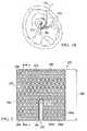
- FIG. 1Aillustrates a schematic of a reduced-pressure treatment system for applying reduced pressure to a tissue site according to an illustrative embodiment
- FIG. 1Billustrates a cross-sectional view of a portion of the reduced-pressure treatment system of FIG. 1A taken along line 1 B- 1 B;
- FIG. 2illustrates a top view of a membrane or manifold for applying reduced pressure to a tissue site according to an illustrative embodiment
- FIG. 3illustrates a perspective view of the membrane of FIG. 2 ;
- FIG. 4illustrates a cross-sectional side view of the membrane of FIG. 2 taken along line 4 - 4 ;
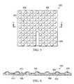
- FIG. 5illustrates a top view of a membrane or manifold for applying reduced pressure to a tissue site according to an illustrative embodiment
- FIG. 6illustrates a cross-sectional side view of the membrane of FIG. 5 taken along line 6 - 6 ;
- FIG. 7illustrates a top view of a membrane or manifold for applying reduced pressure to a tissue site according to an illustrative embodiment
- FIG. 8illustrates a top view of a membrane or manifold for applying reduced pressure to a tissue site according to an illustrative embodiment.
- reduced pressuregenerally refers to a pressure less than the ambient pressure at a tissue site that is being subjected to treatment. In most cases, this reduced pressure will be less than the atmospheric pressure at which the patient is located. Alternatively, the reduced pressure may be less than a hydrostatic pressure associated with tissue at the tissue site. Although the terms “vacuum” and “negative pressure” may be used to describe the pressure applied to the tissue site, the actual pressure reduction applied to the tissue site may be significantly less than the pressure reduction normally associated with a complete vacuum. Reduced pressure may initially generate fluid flow in the area of the tissue site. As the hydrostatic pressure around the tissue site approaches the desired reduced pressure, the flow may subside, and the reduced pressure is then maintained. Unless otherwise indicated, values of pressure stated herein are gauge pressures. Similarly, references to increases in reduced pressure typically refer to a decrease in absolute pressure, while decreases in reduced pressure typically refer to an increase in absolute pressure.
- a reduced-pressure treatment system 100which applies reduced pressure to a tissue site 105 , is shown according to an illustrative embodiment.
- the tissue site 105is a bone tissue site; in particular, the tissue site 105 is a fracture on bone 112 , which, for example, is shown as a femur.
- reduced-pressure treatmentcan increase the rate of healing associated with a fracture, a non-union, a void, or other bone defects.
- Reduced-pressure treatmentmay also be used to improve recovery from osteomyelitis.
- the treatmentmay further be used to increase localized bone densities in patients suffering from osteoporosis.
- reduced-pressure treatmentmay be used to speed and improve osseointegration of orthopedic implants, such as hip implants, knee implants, and fixation devices.
- tissue site 105is bone tissue
- tissue siteas used herein may refer to a wound or defect located on or within any tissue, including but not limited to, bone tissue, adipose tissue, muscle tissue, neural tissue, dermal tissue, vascular tissue, connective tissue, cartilage, tendons, or ligaments.
- tissue sitemay further refer to areas of any tissue that are not necessarily wounded or defective, but are instead areas in which it is desired to add or promote the growth of additional tissue. For example, reduced pressure tissue treatment may be used in certain tissue areas to grow additional tissue that may be harvested and transplanted to another tissue location.
- a reduced pressure treatment system 100includes a reduced pressure source 110 and a reduced pressure dressing 115 that is positioned at the tissue site 105 .
- the reduced pressure dressing 115may include a membrane or manifold 170 positioned at a subcutaneous tissue site, such as tissue site 105 .
- the reduced pressure dressing 115may also include a cover that may be positioned over the membrane 170 . The cover, which is described in more detail below, may be used to seal the membrane 170 at the tissue site and maintain reduced pressure at the tissue site 105 .
- the reduced pressure dressing 115is fluidly connected to the reduced pressure source 110 by a conduit 118 , and a canister 140 may be fluidly connected to the conduit 118 to receive wound exudate or other fluids drawn from the tissue site 105 by the reduced pressure source 110 .
- the conduit 118may be any tube through which a gas, liquid, gel, or other fluid may flow as is described in more detail below.
- the membrane 170is adapted to contact or cover the tissue site 105 .
- coverincludes partially or fully covering.
- a first object that covers a second objectmay directly or indirectly touch the second object, or may not touch the second object at all.
- the membrane 170may be made from a flexible material such that the membrane 170 may be bent to fit against the tissue site 105 .
- the membrane 170is curved against the contour of the tissue site 105 so that a tissue-facing surface 172 of the membrane 170 is in contact with the tissue site 105 .
- the membrane 170may be made from a rigid material that is resistant to bending.
- the membrane 170may have sufficient rigidity to resist collapse when exposed to reduced pressure, yet still maintain relative flexibility for certain applications, such as for percutaneous insertion and placement at the subcutaneous tissue site 105 . Additional embodiments described below show that the membrane 170 may include protrusions and channels on the tissue-facing surface 172 of the membrane 170 .
- the reduced pressure generated by the reduced-pressure source 110may be provided to the membrane 170 by conduit 118 .
- conduit 118may deliver reduced pressure from the reduced-pressure source 110 to the tissue-facing surface 172 of the membrane 170 during treatment.
- Conduit 118may be coupled to the membrane 170 .
- the term “coupled”includes coupling via a separate object.
- conduit 118is coupled to the membrane 170 if both conduit 118 and the membrane 170 are coupled to one or more third objects.
- the term “coupled”also includes “directly coupled,” in which case the two objects touch each other in some way.
- the term “coupled”also encompasses two or more components that are continuous with one another by virtue of each of the components being formed from the same piece of material.
- Coupledincludes chemical coupling, such as via a chemical bond.
- the term “coupled”also includes fluidly coupled, in which case a first object that is coupled to a second object is in fluid communication with that second object.
- the term “coupled”may also include mechanical, thermal, or electrical coupling. Objects that are “coupled” may also be fixedly or removably coupled.
- the conduit 118may be made from any material, and may be either flexible or inflexible.
- the conduit 118may include one or more paths or lumens through which fluid may flow.
- the conduit 118may include two or more lumens, one of which may be used to deliver reduced pressure to the tissue site and one of which may be used to determine the level of reduced pressure at the tissue site 105 .
- one of the lumensmay be used to deliver fluids, such as air, antibacterial agents, antiviral agents, cell-growth promotion agents, irrigation fluids, or other chemically active agents, to the tissue site 105 .
- the reduced pressure source 110is an electrically-driven vacuum pump.
- the reduced pressure source 110may instead be a manually-actuated or manually-charged pump that does not require electrical power.
- the reduced pressure source 110instead may be any other type of reduced pressure pump, or alternatively a wall suction port such as those available in hospitals and other medical facilities.
- the reduced pressure source 110may be housed within or used in conjunction with a reduced pressure treatment unit 119 , which may also contain sensors, processing units, alarm indicators, memory, databases, soft ware, display units, and user interfaces 121 that further facilitate the application of reduced pressure treatment to the tissue site 105 .
- a sensor or switchmay be disposed at or near the reduced pressure source 110 to determine a source pressure generated by the reduced pressure source 110 .
- the sensormay communicate with a processing unit that monitors and controls the reduced pressure that is delivered by the reduced pressure source 110 .
- the reduced-pressure treatment system 100may include a reduced pressure feedback system 155 operably associated with the other components of the reduced-pressure treatment system 100 to provide information to a user of the reduced-pressure treatment system 100 indicating a relative or absolute amount of pressure that is being delivered to the tissue site 105 or that is being generated by the reduced-pressure source 110 .
- feedback systemsinclude, without limitation, pop valves that activate when the reduced pressure rises above a selected value and deflection pop valves.
- the reduced-pressure treatment system 100may include a volume detection system 157 to detect the amount of fluid present in the canister 140 , a blood detection system 159 to detect the presence of blood in exudate drawn from the tissue site 105 (including the exudate that is present in the canister 140 ), a temperature monitoring system 162 to monitor the temperature of the tissue site 105 , an infection detection system 165 to detect the presence of infection at the tissue site 105 , and/or a flow rate monitoring system 167 to monitor the flow rate of fluids drawn from tissue site 105 .
- the infection detection system 165may include a foam or other substance that changes color in the presence of bacteria.
- the foam or other substancemay be operably associated with the dressing 115 or the conduit 118 such that the color changing material is exposed to exudate from the tissue site 105 .
- the reduced-pressure treatment system 100may include valves, regulators, switches, and other electrical, mechanical, and fluid components to facilitate administration of reduced-pressure treatment to the tissue site 105 .
- a membrane 270includes a first, tissue-facing side or surface 272 having a plurality of protrusions 275 on the first, tissue-facing surface 272 .
- the protrusions 275have a substantially triangular shape as viewed in FIG. 2 ; however, in other embodiments, the protrusions 275 may have any shape.
- the protrusions 275are operable to contact a subcutaneous tissue site, such as tissue site 105 in FIG. 1A .
- the membrane 270also includes a second side or surface 273 opposite the first, tissue-facing surface 272 .
- each of the protrusions 275forms a respective recess 276 on the second surface 273 .
- the protrusions 275at least partially define at least one channel.
- the protrusions 275define channels 280 .
- the channels 280are interconnected, and are formed between the protrusions 275 .
- the channels 280include slanted channels 280 a and 280 b , which have an angled or diagonal orientation, as well as lateral channels 280 c , which, in the illustrated embodiment, are substantially perpendicular to at least one edge of the membrane 270 .
- the channels 280intersect at intersection portions 282 .
- the protrusions 275may form discontinuous wall members that define channels according to various patterns. In the embodiment of FIGS. 2-4 , channels radially emanate from the intersection portions 282 in six directions. However, channels may emanate, radially or otherwise, from intersection portions 282 in any number of directions.
- the channels 280are operable to transfer reduced pressure, and the flow of any fluids due to the application of reduced pressure, along the first, tissue-facing surface 272 .
- the reduced pressuremay be provided by a reduced-pressure source, such as reduced-pressure source 110 in FIG. 1A .
- the reduced pressuremay be delivered to the membrane 270 via a delivery tube, such as conduit 118 in FIG. 1A .
- the channels 280may also transfer liquid, such as exudate, along the first, tissue-facing surface 272 of the membrane 270 .
- the liquidmay be drawn into the delivery tube using the reduced pressure, and may be stored in a fluid collection apparatus, such as canister 140 in FIG. 1A .
- the delivery tube or conduitmay be at least partially disposed in a groove 284 disposed on the tissue-facing side 272 of the membrane 270 .
- the groove 284may be a curved groove having a partially circular cross section such that a cylindrical delivery tube may fit into the groove 284 .
- the groove 284 and cylindrical delivery tube, e.g., conduit 118may cooperate to form an interference fit to hold the delivery tube in the groove 284 .
- the conduitmay be adhesively or otherwise secured to the membrane 270 .
- the groove 284may alternatively have a partially polygonal or partially elliptical cross section such that a delivery tube having a polygonal or elliptical cross section, respectively, may be disposed in the groove 284 .
- the presence of the groove 284may facilitate the placement of the membrane 270 over a tissue site by allowing a greater proportion of the first, tissue-facing surface 272 to make contact with the tissue site, including those portions of the tissue-facing surface abutting or adjacent groove 284 .
- the delivery tubemay be coupled to the membrane 270 via the groove 284 .
- the groove 284may be shaped to receive at least a portion of a delivery tube.
- the groove 284may be an open or closed passageway.
- the delivery tubewhen disposed within the groove 284 , may extend to or near a first end 277 of the groove 284 . In another embodiment, the end of the delivery tube may be located anywhere between the first end 277 and a second end 279 of the groove 284 .
- the groove 284is shown to be perpendicular to an edge 286 of the membrane 270 , the groove 284 may have any orientation, such as an angled orientation, relative to the edge 286 . Also, although the groove 284 is shown to be substantially centered along edge 286 , the groove 284 may be located anywhere along the edge 286 . The groove 284 may also be located along any of the other edges of the membrane 270 . In another embodiment, the membrane 270 may have more than one groove 284 . Also, the groove 284 may have any length, including a length that equals the length 288 of the membrane 270 .
- the membrane 270may be made from any material, including any polymer.
- the membrane 270is preferably biocompatible and may be either non-biodegradable or biodegradable (or bio-absorbable), or a combination thereof.
- Non-limiting examples of non-biodegradable materials from which the membrane 270 may be madeinclude a Teflon® material and other fluoro polymers (which can be thermoplastic or thermoset), polyethylene terepthalate glycol (PETG), acrylic, polyethylene (PE), polyurethane (PU), polypropylene (PP), a thermoplastic (including all of the forgoing), silicone, a thermoset, latex, a dipped or cast material (as is latex and as PU can be) or any combination thereof.
- bioabsorbable materials from which the membrane 270 may be madeinclude PGA-polyglycolide, PLA-polyactide, PLA-PGA copolymers, including PLG-poly(lactide-co-glycolide) or DLPLG, PDS-poly(dioxanone), or any other bioabsorbable polymer, or any combination thereof.
- Membrane 270may be porous or non-porous.
- porous membranesinclude foams and woven or non-woven fabrics (including mats and felts). Fabrics may use a variety of filaments including, for example, braided and extruded.
- Non-porous membranesfor example, may be cast, blown, molded, vacuum formed, dipped, or extruded.
- the membrane 270may further serve as a scaffold for new cell-growth, or a scaffold material may be used in conjunction with the membrane 270 to promote cell-growth.
- a scaffoldis a substance or structure used to enhance or promote the growth of cells or formation of tissue, such as a three-dimensional porous structure that provides a template for cell growth.
- Illustrative examples of scaffold materialsinclude calcium phosphate, collagen, PLA/PGA, coral hydroxy apatites, carbonates, or processed allograft materials.
- the membrane 270may be applied to a subcutaneous tissue site, where the membrane 270 may remain and eventually degrade.
- the membrane 270may be configured for in-vivo detachability from a delivery tube, such as conduit 118 in FIG. 1A .
- the groove 284may be coated with a rapid-release adhesive that adheres the delivery tube to the groove 284 during application of the membrane 270 to a tissue site.
- the rapid-release adhesivemay also adhere the delivery tube to the groove 284 during reduced pressure treatment. After a period of time, the rapid-release adhesive may release the delivery tube such that the delivery tube may be removed from the tissue site area while allowing the membrane 270 to remain and degrade at the tissue site.
- the membrane 270may have a membrane wall 289 with a substantially uniform membrane wall thickness 290 .
- the membrane wall thickness 290may be contrasted to the membrane thickness 291 .
- Providing a substantially uniform membrane wall thickness 290is one way to help ensure that each portion of the membrane 270 degrades in approximately the same amount of time (assuming a constant bioabsorption rate).
- the membrane wall thickness of a particular membranewill not always be substantially uniform.
- One particular method of manufacturing the membranes described hereininvolves vacuum forming. While vacuum forming may be particularly cost effective, the manufacturing technique will sometimes result in “low points” between protrusions being thicker than the “high points” associated with the protrusions. A similar circumstance may occur if the membrane is formed by a dipping process. Although in these circumstances the membrane wall thickness may not be substantially uniform, the benefit of having the membrane material mass well-distributed can still be obtained. As mentioned previously, and as illustrated in FIG. 4 , for each protrusion 275 formed on one side of the membrane 270 , a corresponding recess 276 exists on the opposite side of the membrane 270 .
- the membrane 270may be associated with a medial plane 295 (illustrated as a line in FIG. 4 ) that substantially bisects the membrane thickness 291 .
- deviations from the plane 295 on one side of the membraneare substantially matched by similar deviations on another side of the membrane as illustrated in FIG. 4 to improve the distribution of mass throughout the membrane.
- the membranemay not be associated with a medial plane, but still may include non-planar, matched deviations on opposite sides of the membrane. Matched deviations will typically be similar (but not necessarily exact) in shape and size and will be located relative to one another such that a positively extending structure on one side will correspond with a negatively extending structure on the opposite side (e.g. a projection and a recess).
- matched or similar deviations on opposite sides of the membraneis different than membranes that include a substantially planar sheet from which projections extend on one side of the planar sheet.
- Substantially matched deviations or substantially matched projections and recessesallow customization of the force pattern applied to tissues on each side of the membrane.
- Reduced pressuremay be communicated to both sides of the membrane 270 by either using a porous membrane material, by providing apertures in the membrane, or by providing a delivery tube or conduit on each side of the membrane.
- tissue on one side of the membraneit may be desired to expose tissues on one side of the membrane to a different force pattern than tissues on the other side of the membrane.
- the exposure of a tissue to reduced pressure in the presence of a projectionsubjects the tissue to compressive forces as the tissue is pulled against the projection.
- Tissues exposed to reduced pressure near a recesseswill typically experience tensile forces as the tissue is stretched and pulled into the recesses.
- certain areas of tissue on a “projection” side of the membranemay also be subjected to tensile forces if these areas of tissue are pulled into the channels or depressions between projections.
- the channels or depressionsmay act similar to projections on the “recess” side of the membrane, thereby subjecting tissues adjacent the areas between recesses to compressive forces.
- Projection and recess geometrymay be selected for increased or reduced tissue compression or increased or reduced tissue tension. Sharper projections can increase compression over a small area while broader projections can distribute the compression over a larger area. Similarly, larger recesses can increase the tension seen be tissues. These effects will be dependent on tissue mechanical properties as well as geometry. It should be noted that the projections on one side of the membrane may be shaped to be more sharply defined or pointed, and the recesses corresponding with each of these projections could be shaped to be more rounded or dull. Similarly, the projections could be shaped more broadly or rounded, and the recesses shaped more sharply to further customize the force profile applied to tissue on each side of the membrane.
- the membranemay be designed to ensure a substantially symmetric force distribution on each side of the membrane.
- offset projectionsmay be provided on each side of the membrane that are similar in shape and size and that include recesses between the projections (on each side of the membrane) that are similar in shape and size.
- a membranemay be provided in which the projections and recesses are defined on each side by a substantially sinusoidal cross-sectional profile.
- Other examples of providing a symmetric force distributionare also possible.
- the bioabsorbable material from which the membrane 270 may be mademay also include antibiotics or growth factors.
- the antibiotics or growth factorsmay be released at the tissue site as the membrane 270 degrades.
- the bioabsorbable material in which the antibiotics or growth factors are embeddedis selected such that the antibiotics or growth factors are released at a predetermined rate.
- a bioabsorbable material having a relatively slower rate of degradationmay be selected such that the embedded antibiotics or growth factors are released at the tissue site at a relatively slower rate.
- the membrane 270may include radio opaque markers 299 made from a radio opaque material, such a gold, platinum, or an alloy such as Pt/Ir.
- the radio opaque markers 299may be discrete metal radio opaque markers.
- the radio opaque markers 299may be applied to the membrane 270 in any manner.
- the radio opaque markers 299may be bonded, printed or painted on the membrane 270 .
- the radio opaque markers 299may also be located anywhere on or in the membrane 270 .
- the radio opaque markers 299facilitate the detection of the membrane 270 using x-rays.
- the radio opaque markers 299may help to determine whether a membrane made from a biodegradable material has degraded.
- the membrane 270may be transparent, opaque, or have both transparent and opaque characteristics.
- the membrane 270may include a radio opaque compound, such as barium sulfate or bismuth carbonate, in the resin or material used to form the membrane. Such a radio opaque compound may also be used to form the radio opaque markers 299 .
- the radio opaque material from which the membrane 270 or the radio opaque markers 299 may be mademay optionally include compounds that the body can readily absorb, degrade, or excrete (e.g., iodine or iodine compounds).
- the radio opaque materialmay also include compounds that are visible by magnetic resonance imagining (MRI), such as chelated gadolinium.
- MRImagnetic resonance imagining
- the membrane 270may have any membrane wall thickness 290 , and the thickness 290 may be chosen to achieve a desired effect. For example, if a particular duration (T 1 ) is desired for membrane 270 before the membrane 270 is absorbed and if the bio-absorption rate of the material is high, the membrane wall thickness 290 may be increased to achieve the desired duration (T 1 ) or if the bio-absorption rate of the material is relatively low, a small membrane wall thickness 290 might be used to achieve the desired duration (T 1 ).
- a relatively thin wall thickness 290might be used to achieve the desired flexibility or if the material from which the membrane wall thickness 290 is made is relatively flexible, a thicker member wall thickness 290 might be used to achieve the desired flexibility. Controlling the material variables and properties, e.g., absorption rate, thickness, and stiffness, may be particularly applicable to clinical situations in which the resistance to collapse when exposed to a therapeutic level of reduced pressure is required and a particular duration may be desired.
- the membrane wall thickness 290 of the membrane 270may be chosen to adjust the length of time needed for the membrane 270 to absorb. In another embodiment, the membrane wall thickness 290 of the membrane 270 may also be chosen to adjust the amount of antibiotics or growth factors that may be contained by the membrane 270 . In another embodiment, the membrane wall thickness 290 of the membrane 270 may be chosen to adjust the surface area to volume ratio of the membrane 270 , thereby changing the rate at which the membrane 270 absorbs. As mentioned previously, the membrane wall thickness may or may not be substantially uniform (i.e. substantially the same thickness) throughout the membrane.
- the membrane 270was formed from polypropylene and had a membrane wall thickness 290 in the range of 0.005′′ to 0.050′′ and more particularly in the range of 0.010′′ to 0.040, and even more particularly in the range of 0.015 to 0.025, and in particular a membrane wall thickness 290 of 0.020′′.
- the membrane wall thickness 290may vary throughout the membrane such that wall thickness 290 may be, for example, thicker along channels 280 a , 280 b and 280 c and thinner at protrusions 275 .
- a method for applying reduced pressure to a subcutaneous tissue sitemay include applying a membrane as described in any of the illustrative embodiments, such as membrane 270 , to the subcutaneous tissue site.
- the membrane 270is applied to the subcutaneous tissue site such that the first, tissue-facing surface 272 of the membrane 270 faces the subcutaneous tissue site.
- the first, tissue-facing surface 272may be in direct or indirect contact with the subcutaneous tissue site.
- applying the membrane 270 to the subcutaneous tissue siteincludes bending, rolling, unrolling, or otherwise changing the shape of the membrane 270 to facilitate percutaneous insertion or subcutaneous placement of the membrane 270 .
- the methodmay also include supplying reduced pressure to the first, tissue-facing surface 272 of the membrane 270 via a delivery tube, such as conduit 118 in FIG. 1A , which is coupled to the membrane 270 .
- the reduced pressureis from a reduced-pressure source, such as reduced-pressure source 110 in FIG. 1A .
- the methodmay also include transferring the reduced pressure along the first, tissue-facing surface 272 of the membrane 270 during treatment.
- the reduced pressuremay be at least partially transferred via the channels 280 ; in this example, the space that is formed by the channels 280 and the tissue site may form a passage through which reduced pressure may be transferred.
- reduced pressuremay also be partially transferred through membrane 270 itself.
- a method of manufacturing an apparatus for applying reduced pressure to a subcutaneous tissue siteincludes forming a membrane as in any of the illustrative embodiments disclosed herein, including the membrane 270 .
- forming the membraneincludes vacuum molding the membrane 270 .
- the membrane 270may also be formed using injection molding, compression molding, or casting. Any of these methods of forming the membrane 270 may be used to create channels, such as channels 280 , in a planar membrane. Any of these methods may also facilitate the economical manufacturing of the membrane 270 .
- the method of manufacturing the apparatusmay also include providing a delivery tube, such as conduit 118 in FIG. 1A , for delivering the reduced pressure to the first, tissue-facing surface 272 of the membrane 270 .
- the method of manufacturingmay also include coupling the delivery tube to the membrane 270 such that the delivery tube is in fluid communication with the first, tissue-facing surface 272 of the membrane 270 .
- a membrane 570includes a tissue-facing surface 572 having protrusions 575 that have a dome shape.
- the protrusions 575have a circular shape.
- the protrusions 575may have any shape as viewed in FIG. 5 , including an elliptical, diamond, polygonal, or elongated shape.
- the protrusions 575may have a semi-ellipsoidal shape.
- one or more of the protrusions 575may have a shape that is different from the remainder of the protrusions 575 .
- the membrane 570also includes channels 580 , which are at least partially defined by the protrusions 575 , and are analogous to channels 280 in FIGS. 2-4 .
- the channels 580facilitate the transfer of reduced pressure or fluids along the tissue-facing surface 572 of the membrane 570 .
- the membrane 570may include a backing sheet 592 , which is coupled to a surface 573 of the membrane 570 .
- the flexible backing sheet 592may be composed of a biodegradable or non-biodegradable material, and may add strength and durability to the membrane 570 .
- the membrane 570may be coupled to the backing sheet 592 in any manner, such as by using welding (e.g., ultrasonic or RF), bonding, adhesives (e.g., silicone adhesive), cements, etc.
- the membrane 570may include a coating 594 that at least partially covers the membrane 570 .
- the coating 594may cover any surface of the membrane 570 , including the surface 573 .
- the coating 594may also cover any surface of the backing sheet 592 , including the surface 596 of the backing sheet 592 .
- the coating 594may be at least partially composed of a hydrogel.
- the coating 594 of hydrogelmay reduce friction at the surface of the membrane 570 that is covered by the coating 594 .
- the coating 594 of hydrogelmay facilitate the percutaneous insertion of the membrane 570 and subcutaneous application and placement of the membrane 570 at the tissue site.
- the coating 594may be at least partially composed of heparin. In this embodiment, the coating 594 may reduce or prevent the formation of clots at the tissue site or elsewhere. In still another embodiment, the coating 594 may also include antibiotics or growth factors. In another embodiment, the coating 594 may also be at least partially composed of poly(ethylene glycol) (PEG).
- PEGpoly(ethylene glycol)
- Each of the protrusions 575 of membrane 570form a respective hollow recess 576 along the surface 573 of the membrane 570 .
- Each recess 576may be filled with a material, such as the material from which the membrane 570 is made; in this example, each recess 576 is not hollow and the membrane 570 does not have a substantially uniform wall thickness.
- the membrane 570may absorb to result in a distributed array of degradable protrusions 575 (e.g., 0.60′′ ⁇ 0.060′′) after the degradation of the thinner (e.g. 0.020′′) portions of the membrane 570 .
- each recess 576may include a drug, a growth factor, or an antibiotic; in this embodiment, the drug in each recess 576 may be delivered to a tissue site as the protrusions 575 of the membrane 570 absorb.
- the membrane 570may have a substantially uniform membrane wall thickness or may have matched or similar deviations on opposite sides of the membrane 570 as described previously with reference to membrane 270 .
- a membrane 770includes a tissue-facing surface 772 showing protrusions 775 a and 775 b that are elongated.
- Each of the protrusions 775 ahas an end 710 and an end 712 .
- the end 710 of each of the protrusions 775 ais adjacent a groove 784 .
- the end 712 of each of the protrusions 775 ais adjacent at least one of the edges, e.g., edge 785 , of the membrane 770 .
- the protrusions 775 aextend radially from near or at an end 777 of the groove 784 . Any number of protrusions may extend radially from the groove 784 .
- the protrusions 775 amay extend radially from portions of the groove 784 other than the end 777 .
- the protrusions 775 aat least partially form elongated channels 780 a , which may be similar to the channels 280 in FIGS. 2-4 .
- Each of the channels 780 ahas a channel end 720 and a channel end 722 .
- the channel end 720 of each of the channels 780 ais adjacent the groove 784 .
- the channel end 722 of each of the channels 780 ais adjacent at least one edge of the membrane 770 .
- the channels 780 aare also tapered such that the channel end 722 is wider than the channel end 720 .
- the membrane 770also includes elongated protrusions 775 b , which are substantially perpendicular to the groove 784 .
- Each of the protrusions 775 bis also substantially parallel to one another.
- Each of the protrusions 775 bhas an end 716 and an end 718 .
- the end 716 of each of the protrusions 775 bis adjacent the groove 784 .
- the end 718 of each of the protrusions 775 bis adjacent at least one edge of the membrane 770 .
- the protrusions 775 bat least partially form elongated channels 780 b , which are similar to the channels 280 in FIGS. 2-4 .
- the channels 780 bare substantially perpendicular to the groove 784 .
- Each of the channels 780 bhas an end 724 and an end 726 .
- the end 724 of each of the channels 780 bis adjacent the groove 784 .
- the end 726 of each of the channels 780 bis adjacent at least one edge of the membrane 770 .
- Each of the protrusions 775 a and 775 bmay have any width 714 .
- the width 714 of each of the protrusions 775 a and 775 bmay be uniform or non-uniform.
- at least a portion of the protrusions 775 a and 775 bmay be tapered such that one end of the protrusions 775 a and 775 b , such as ends 710 and 716 , respectively, may have a smaller width than the other end of the protrusions 775 a and 775 b , such as ends 712 and 718 , respectively.
- all of the protrusions 775 a and 775 bmay extend radially from a portion of the groove 784 , such as the end 777 of the groove 784 .
- the channels 780 a and 780 bmay instead form protrusions that form channels; in this embodiment, the protrusions 775 a and 775 b are channels instead of protrusions.
- the membrane 770may have a substantially uniform membrane wall thickness or may have matched or similar deviations on opposite sides of the membrane 770 as described previously with reference to membrane 270 .
- a membrane 870includes a tissue-facing surface 872 having protrusions 875 , which are similar to the protrusions 275 in FIGS. 2-4 .
- Each of the protrusions 875is substantially perpendicular to a groove 884 .
- Each of the protrusions 875is also substantially parallel to one another.
- Each of the protrusions 875has an end 816 and an end 818 .
- the end 816 of each of the protrusions 875is adjacent the groove 884 .
- the end 818 of each of the protrusions 875is adjacent at least one edge of the membrane 870 .
- the protrusions 875at least partially form elongated channels 880 , which are similar to the channels 280 in FIGS. 2-4 .
- the channels 880are substantially perpendicular to the groove 884 .
- Each of the channels 880is also substantially parallel to one another.
- Each of the channels 880has an end 824 and an end 826 .
- the end 824 of each of the channels 880is adjacent the groove 884 .
- the end 826 of each of the channels 880is adjacent at least one edge of the membrane 870 .
- the membrane 870also includes gap 825 between the end 816 of each of the protrusions 875 and the groove 884 .
- the gap 825may be any distance, or may be omitted altogether.
- the membrane 870may have a substantially uniform membrane wall thickness or may have matched or similar deviations on opposite sides of the membrane 870 as described previously with reference to membrane 270 .
Landscapes
- Health & Medical Sciences (AREA)
- Heart & Thoracic Surgery (AREA)
- Life Sciences & Earth Sciences (AREA)
- Veterinary Medicine (AREA)
- Public Health (AREA)
- General Health & Medical Sciences (AREA)
- Animal Behavior & Ethology (AREA)
- Biomedical Technology (AREA)
- Engineering & Computer Science (AREA)
- Vascular Medicine (AREA)
- Hematology (AREA)
- Anesthesiology (AREA)
- Medicinal Chemistry (AREA)
- Dermatology (AREA)
- Chemical & Material Sciences (AREA)
- Oral & Maxillofacial Surgery (AREA)
- Transplantation (AREA)
- Epidemiology (AREA)
- Otolaryngology (AREA)
- Media Introduction/Drainage Providing Device (AREA)
- Surgical Instruments (AREA)
- Materials For Medical Uses (AREA)
Abstract
Description
Claims (31)
Priority Applications (2)
| Application Number | Priority Date | Filing Date | Title |
|---|---|---|---|
| US12/643,856US9327064B2 (en) | 2008-12-24 | 2009-12-21 | Membranes, systems, and methods for applying reduced pressure to a subcutaneous tissue site |
| TW098144829ATW201029693A (en) | 2008-12-24 | 2009-12-24 | Membranes, systems, and methods for applying reduced pressure to a subcutaneous tissue site |
Applications Claiming Priority (2)
| Application Number | Priority Date | Filing Date | Title |
|---|---|---|---|
| US14065708P | 2008-12-24 | 2008-12-24 | |
| US12/643,856US9327064B2 (en) | 2008-12-24 | 2009-12-21 | Membranes, systems, and methods for applying reduced pressure to a subcutaneous tissue site |
Publications (2)
| Publication Number | Publication Date |
|---|---|
| US20100160877A1 US20100160877A1 (en) | 2010-06-24 |
| US9327064B2true US9327064B2 (en) | 2016-05-03 |
Family
ID=42267167
Family Applications (1)
| Application Number | Title | Priority Date | Filing Date |
|---|---|---|---|
| US12/643,856Active2031-12-11US9327064B2 (en) | 2008-12-24 | 2009-12-21 | Membranes, systems, and methods for applying reduced pressure to a subcutaneous tissue site |
Country Status (12)
| Country | Link |
|---|---|
| US (1) | US9327064B2 (en) |
| EP (1) | EP2367579B1 (en) |
| JP (1) | JP5345703B2 (en) |
| KR (1) | KR20110102918A (en) |
| CN (1) | CN102256638B (en) |
| AU (1) | AU2009330157B2 (en) |
| CA (2) | CA2989646C (en) |
| MX (1) | MX2011006808A (en) |
| RU (1) | RU2011122550A (en) |
| SG (1) | SG171797A1 (en) |
| TW (1) | TW201029693A (en) |
| WO (1) | WO2010075313A2 (en) |
Families Citing this family (26)
| Publication number | Priority date | Publication date | Assignee | Title |
|---|---|---|---|---|
| ES2715605T3 (en) | 2007-11-21 | 2019-06-05 | Smith & Nephew | Wound dressing |
| US8882730B2 (en) | 2010-03-12 | 2014-11-11 | Kci Licensing, Inc. | Radio opaque, reduced-pressure manifolds, systems, and methods |
| CA140188S (en) | 2010-10-15 | 2011-11-07 | Smith & Nephew | Medical dressing |
| CA140189S (en) | 2010-10-15 | 2011-11-07 | Smith & Nephew | Medical dressing |
| MX364446B (en)* | 2011-04-15 | 2019-04-26 | Univ Massachusetts | Surgical cavity drainage and closure system. |
| WO2012170744A2 (en)* | 2011-06-07 | 2012-12-13 | Spiracur, Inc. | Solutions for bridging and pressure concentration reduction at wound sites |
| JP6202686B2 (en)* | 2011-11-18 | 2017-09-27 | ケーシーアイ ライセンシング インコーポレイテッド | Tissue treatment system and method having a porous substrate having a contraction region and an expansion region |
| CN108186200B (en) | 2012-08-01 | 2021-08-10 | 史密夫及内修公开有限公司 | Wound dressing |
| WO2014020440A1 (en)* | 2012-08-01 | 2014-02-06 | Smith & Nephew Plc | Wound dressing |
| EP2897662B1 (en) | 2012-09-20 | 2020-05-06 | Lohmann & Rauscher GmbH | Vacuum treatment array and film for producing a vacuum treatment array |
| DE102012025125A1 (en) | 2012-12-21 | 2014-06-26 | Paul Hartmann Ag | Absorbent body for the therapeutic treatment of a wound by means of negative pressure |
| US8893721B2 (en) | 2013-03-15 | 2014-11-25 | Futrell Medical Corporation | Surgical drape with vapor evacuation |
| JP2017512620A (en)* | 2014-03-28 | 2017-05-25 | スリーエム イノベイティブ プロパティズ カンパニー | Articles and methods for negative pressure wound closure therapy |
| EP3441051B1 (en)* | 2015-01-14 | 2021-07-21 | 3M Innovative Properties Company | Closed abdominal manifold dressing |
| WO2017119996A1 (en)* | 2016-01-06 | 2017-07-13 | Kci Liecensing, Inc. | System and methods for the treatment of wounds with dressing having closed cells |
| US11432967B2 (en)* | 2017-10-23 | 2022-09-06 | Kci Licensing, Inc. | Fluid bridge for simultaneous application of negative pressure to multiple tissue sites |
| WO2019084006A1 (en)* | 2017-10-23 | 2019-05-02 | Kci Licensing, Inc. | Low profile distribution components for wound therapy |
| FR3074031A1 (en)* | 2017-11-30 | 2019-05-31 | F.D.S. | FLUIDIC DEVICE FOR HANDLING A LIQUID, MULTILAYER COMPLEX COMPRISING SUCH A DEVICE, AND METHOD OF MANUFACTURING THE SAME |
| JP7606347B2 (en)* | 2018-03-12 | 2024-12-25 | スリーエム イノベイティブ プロパティズ カンパニー | Dressing with different surface features used in compartmentalized spaces |
| US11534343B2 (en)* | 2018-07-31 | 2022-12-27 | Kci Licensing, Inc. | Devices and methods for preventing localized pressure points in distribution components for tissue therapy |
| WO2020081391A1 (en)* | 2018-10-15 | 2020-04-23 | Kci Licensing, Inc. | Micro balloon-on-tube wound filler |
| USD961782S1 (en) | 2018-10-23 | 2022-08-23 | Kci Licensing, Inc. | Low-profile fluid conductor for tissue therapy |
| JP7664174B2 (en)* | 2019-04-08 | 2025-04-17 | スリーエム イノベイティブ プロパティズ カンパニー | Low profile infusion and negative pressure bridge |
| US11160917B2 (en) | 2020-01-22 | 2021-11-02 | J&M Shuler Medical Inc. | Negative pressure wound therapy barrier |
| AU2021385936A1 (en)* | 2020-11-24 | 2023-07-13 | Aroa Biosurgery Limited | Fluid drainage and delivery device for wound treatment |
| EP4251110A4 (en)* | 2020-11-24 | 2024-10-23 | Aroa Biosurgery Limited | BANDAGE |
Citations (161)
| Publication number | Priority date | Publication date | Assignee | Title |
|---|---|---|---|---|
| US1355846A (en) | 1920-02-06 | 1920-10-19 | David A Rannells | Medical appliance |
| US2177490A (en)* | 1936-04-09 | 1939-10-24 | John E Kieffer | Art of making indented material |
| US2547758A (en) | 1949-01-05 | 1951-04-03 | Wilmer B Keeling | Instrument for treating the male urethra |
| US2632443A (en) | 1949-04-18 | 1953-03-24 | Eleanor P Lesher | Surgical dressing |
| GB692578A (en) | 1949-09-13 | 1953-06-10 | Minnesota Mining & Mfg | Improvements in or relating to drape sheets for surgical use |
| US2682873A (en) | 1952-07-30 | 1954-07-06 | Johnson & Johnson | General purpose protective dressing |
| US2910763A (en) | 1955-08-17 | 1959-11-03 | Du Pont | Felt-like products |
| US2969057A (en) | 1957-11-04 | 1961-01-24 | Brady Co W H | Nematodic swab |
| US3066672A (en) | 1960-09-27 | 1962-12-04 | Jr William H Crosby | Method and apparatus for serial sampling of intestinal juice |
| US3367332A (en) | 1965-08-27 | 1968-02-06 | Gen Electric | Product and process for establishing a sterile area of skin |
| US3520300A (en) | 1967-03-15 | 1970-07-14 | Amp Inc | Surgical sponge and suction device |
| US3568675A (en) | 1968-08-30 | 1971-03-09 | Clyde B Harvey | Fistula and penetrating wound dressing |
| US3648692A (en) | 1970-12-07 | 1972-03-14 | Parke Davis & Co | Medical-surgical dressing for burns and the like |
| US3682180A (en) | 1970-06-08 | 1972-08-08 | Coilform Co Inc | Drain clip for surgical drain |
| US3826254A (en) | 1973-02-26 | 1974-07-30 | Verco Ind | Needle or catheter retaining appliance |
| US3832267A (en)* | 1972-09-19 | 1974-08-27 | Hercules Inc | Embossed film |
| US3992162A (en)* | 1955-06-09 | 1976-11-16 | Marc Wood International, Inc. | Sheet with alternate protrusions and recesses |
| DE2640413A1 (en) | 1976-09-08 | 1978-03-09 | Wolf Gmbh Richard | CATHETER MONITORING DEVICE |
| US4080970A (en) | 1976-11-17 | 1978-03-28 | Miller Thomas J | Post-operative combination dressing and internal drain tube with external shield and tube connector |
| US4096853A (en) | 1975-06-21 | 1978-06-27 | Hoechst Aktiengesellschaft | Device for the introduction of contrast medium into an anus praeter |
| US4139004A (en) | 1977-02-17 | 1979-02-13 | Gonzalez Jr Harry | Bandage apparatus for treating burns |
| US4165748A (en) | 1977-11-07 | 1979-08-28 | Johnson Melissa C | Catheter tube holder |
| US4184510A (en) | 1977-03-15 | 1980-01-22 | Fibra-Sonics, Inc. | Valued device for controlling vacuum in surgery |
| WO1980002182A1 (en) | 1979-04-06 | 1980-10-16 | J Moss | Portable suction device for collecting fluids from a closed wound |
| US4233969A (en) | 1976-11-11 | 1980-11-18 | Lock Peter M | Wound dressing materials |
| US4245630A (en) | 1976-10-08 | 1981-01-20 | T. J. Smith & Nephew, Ltd. | Tearable composite strip of materials |
| US4256109A (en) | 1978-07-10 | 1981-03-17 | Nichols Robert L | Shut off valve for medical suction apparatus |
| US4261363A (en) | 1979-11-09 | 1981-04-14 | C. R. Bard, Inc. | Retention clips for body fluid drains |
| US4275721A (en) | 1978-11-28 | 1981-06-30 | Landstingens Inkopscentral Lic, Ekonomisk Forening | Vein catheter bandage |
| US4284079A (en) | 1979-06-28 | 1981-08-18 | Adair Edwin Lloyd | Method for applying a male incontinence device |
| US4297995A (en) | 1980-06-03 | 1981-11-03 | Key Pharmaceuticals, Inc. | Bandage containing attachment post |
| US4333468A (en) | 1980-08-18 | 1982-06-08 | Geist Robert W | Mesentery tube holder apparatus |
| US4343848A (en)* | 1980-12-15 | 1982-08-10 | Ethyl Corporation | Embossed thermoplastic material |
| US4373519A (en) | 1981-06-26 | 1983-02-15 | Minnesota Mining And Manufacturing Company | Composite wound dressing |
| US4382441A (en) | 1978-12-06 | 1983-05-10 | Svedman Paul | Device for treating tissues, for example skin |
| US4392853A (en) | 1981-03-16 | 1983-07-12 | Rudolph Muto | Sterile assembly for protecting and fastening an indwelling device |
| US4392858A (en) | 1981-07-16 | 1983-07-12 | Sherwood Medical Company | Wound drainage device |
| US4419097A (en) | 1981-07-31 | 1983-12-06 | Rexar Industries, Inc. | Attachment for catheter tube |
| EP0100148A1 (en) | 1982-07-06 | 1984-02-08 | Dow Corning Limited | Medical-surgical dressing and a process for the production thereof |
| US4465485A (en) | 1981-03-06 | 1984-08-14 | Becton, Dickinson And Company | Suction canister with unitary shut-off valve and filter features |
| EP0117632A2 (en) | 1983-01-27 | 1984-09-05 | Johnson & Johnson Products Inc. | Adhesive film dressing |
| US4475909A (en) | 1982-05-06 | 1984-10-09 | Eisenberg Melvin I | Male urinary device and method for applying the device |
| US4480638A (en) | 1980-03-11 | 1984-11-06 | Eduard Schmid | Cushion for holding an element of grafted skin |
| US4525374A (en) | 1984-02-27 | 1985-06-25 | Manresa, Inc. | Treating hydrophobic filters to render them hydrophilic |
| US4525166A (en) | 1981-11-21 | 1985-06-25 | Intermedicat Gmbh | Rolled flexible medical suction drainage device |
| US4533352A (en)* | 1983-03-07 | 1985-08-06 | Pmt Inc. | Microsurgical flexible suction mat |
| US4540412A (en) | 1983-07-14 | 1985-09-10 | The Kendall Company | Device for moist heat therapy |
| US4543100A (en) | 1983-11-01 | 1985-09-24 | Brodsky Stuart A | Catheter and drain tube retainer |
| US4548202A (en) | 1983-06-20 | 1985-10-22 | Ethicon, Inc. | Mesh tissue fasteners |
| US4551139A (en) | 1982-02-08 | 1985-11-05 | Marion Laboratories, Inc. | Method and apparatus for burn wound treatment |
| EP0161865A2 (en) | 1984-05-03 | 1985-11-21 | Smith and Nephew Associated Companies p.l.c. | Adhesive wound dressing |
| US4569348A (en) | 1980-02-22 | 1986-02-11 | Velcro Usa Inc. | Catheter tube holder strap |
| US4605399A (en) | 1984-12-04 | 1986-08-12 | Complex, Inc. | Transdermal infusion device |
| US4608041A (en) | 1981-10-14 | 1986-08-26 | Frese Nielsen | Device for treatment of wounds in body tissue of patients by exposure to jets of gas |
| US4640688A (en) | 1985-08-23 | 1987-02-03 | Mentor Corporation | Urine collection catheter |
| US4655754A (en) | 1984-11-09 | 1987-04-07 | Stryker Corporation | Vacuum wound drainage system and lipids baffle therefor |
| US4664662A (en) | 1984-08-02 | 1987-05-12 | Smith And Nephew Associated Companies Plc | Wound dressing |
| WO1987004626A1 (en) | 1986-01-31 | 1987-08-13 | Osmond, Roger, L., W. | Suction system for wound and gastro-intestinal drainage |
| US4710165A (en) | 1985-09-16 | 1987-12-01 | Mcneil Charles B | Wearable, variable rate suction/collection device |
| US4711781A (en)* | 1984-06-23 | 1987-12-08 | Erich Nick | Medicinal self-adhesive plaster |
| US4733659A (en) | 1986-01-17 | 1988-03-29 | Seton Company | Foam bandage |
| GB2195255A (en) | 1986-09-30 | 1988-04-07 | Vacutec Uk Limited | Method and apparatus for vacuum treatment of an epidermal surface |
| US4743232A (en) | 1986-10-06 | 1988-05-10 | The Clinipad Corporation | Package assembly for plastic film bandage |
| GB2197789A (en) | 1986-11-28 | 1988-06-02 | Smiths Industries Plc | Anti-foaming disinfectants used in surgical suction apparatus |
| US4758220A (en) | 1985-09-26 | 1988-07-19 | Alcon Laboratories, Inc. | Surgical cassette proximity sensing and latching apparatus |
| US4787888A (en) | 1987-06-01 | 1988-11-29 | University Of Connecticut | Disposable piezoelectric polymer bandage for percutaneous delivery of drugs and method for such percutaneous delivery (a) |
| US4826494A (en) | 1984-11-09 | 1989-05-02 | Stryker Corporation | Vacuum wound drainage system |
| US4838883A (en) | 1986-03-07 | 1989-06-13 | Nissho Corporation | Urine-collecting device |
| US4840187A (en) | 1986-09-11 | 1989-06-20 | Bard Limited | Sheath applicator |
| US4863449A (en) | 1987-07-06 | 1989-09-05 | Hollister Incorporated | Adhesive-lined elastic condom cathether |
| US4872450A (en) | 1984-08-17 | 1989-10-10 | Austad Eric D | Wound dressing and method of forming same |
| US4878901A (en) | 1986-10-10 | 1989-11-07 | Sachse Hans Ernst | Condom catheter, a urethral catheter for the prevention of ascending infections |
| GB2220357A (en) | 1988-05-28 | 1990-01-10 | Smiths Industries Plc | Medico-surgical containers |
| US4897081A (en) | 1984-05-25 | 1990-01-30 | Thermedics Inc. | Percutaneous access device |
| US4906240A (en) | 1988-02-01 | 1990-03-06 | Matrix Medica, Inc. | Adhesive-faced porous absorbent sheet and method of making same |
| US4906233A (en) | 1986-05-29 | 1990-03-06 | Terumo Kabushiki Kaisha | Method of securing a catheter body to a human skin surface |
| US4919654A (en) | 1988-08-03 | 1990-04-24 | Kalt Medical Corporation | IV clamp with membrane |
| CA2005436A1 (en) | 1988-12-13 | 1990-06-13 | Glenda G. Kalt | Transparent tracheostomy tube dressing |
| US4941882A (en) | 1987-03-14 | 1990-07-17 | Smith And Nephew Associated Companies, P.L.C. | Adhesive dressing for retaining a cannula on the skin |
| US4953565A (en) | 1986-11-26 | 1990-09-04 | Shunro Tachibana | Endermic application kits for external medicines |
| WO1990010424A1 (en) | 1989-03-16 | 1990-09-20 | Smith & Nephew Plc | Absorbent devices and precursors therefor |
| US4969880A (en) | 1989-04-03 | 1990-11-13 | Zamierowski David S | Wound dressing and treatment method |
| US4985019A (en) | 1988-03-11 | 1991-01-15 | Michelson Gary K | X-ray marker |
| GB2235877A (en) | 1989-09-18 | 1991-03-20 | Antonio Talluri | Closed wound suction apparatus |
| US5037397A (en) | 1985-05-03 | 1991-08-06 | Medical Distributors, Inc. | Universal clamp |
| US5086170A (en) | 1989-01-16 | 1992-02-04 | Roussel Uclaf | Process for the preparation of azabicyclo compounds |
| US5092858A (en) | 1990-03-20 | 1992-03-03 | Becton, Dickinson And Company | Liquid gelling agent distributor device |
| US5100396A (en) | 1989-04-03 | 1992-03-31 | Zamierowski David S | Fluidic connection system and method |
| US5134994A (en) | 1990-02-12 | 1992-08-04 | Say Sam L | Field aspirator in a soft pack with externally mounted container |
| US5149331A (en) | 1991-05-03 | 1992-09-22 | Ariel Ferdman | Method and device for wound closure |
| US5167613A (en) | 1992-03-23 | 1992-12-01 | The Kendall Company | Composite vented wound dressing |
| US5176663A (en) | 1987-12-02 | 1993-01-05 | Pal Svedman | Dressing having pad with compressibility limiting elements |
| WO1993009727A1 (en) | 1991-11-14 | 1993-05-27 | Wake Forest University | Method and apparatus for treating tissue damage |
| US5215522A (en) | 1984-07-23 | 1993-06-01 | Ballard Medical Products | Single use medical aspirating device and method |
| US5232453A (en) | 1989-07-14 | 1993-08-03 | E. R. Squibb & Sons, Inc. | Catheter holder |
| US5261893A (en) | 1989-04-03 | 1993-11-16 | Zamierowski David S | Fastening system and method |
| US5278100A (en) | 1991-11-08 | 1994-01-11 | Micron Technology, Inc. | Chemical vapor deposition technique for depositing titanium silicide on semiconductor wafers |
| US5279550A (en) | 1991-12-19 | 1994-01-18 | Gish Biomedical, Inc. | Orthopedic autotransfusion system |
| US5298015A (en) | 1989-07-11 | 1994-03-29 | Nippon Zeon Co., Ltd. | Wound dressing having a porous structure |
| US5342376A (en) | 1993-05-03 | 1994-08-30 | Dermagraphics, Inc. | Inserting device for a barbed tissue connector |
| US5344415A (en) | 1993-06-15 | 1994-09-06 | Deroyal Industries, Inc. | Sterile system for dressing vascular access site |
| DE4306478A1 (en) | 1993-03-02 | 1994-09-08 | Wolfgang Dr Wagner | Drainage device, in particular pleural drainage device, and drainage method |
| WO1994020041A1 (en) | 1993-03-09 | 1994-09-15 | Wake Forest University | Wound treatment employing reduced pressure |
| US5358494A (en) | 1989-07-11 | 1994-10-25 | Svedman Paul | Irrigation dressing |
| US5437651A (en) | 1993-09-01 | 1995-08-01 | Research Medical, Inc. | Medical suction apparatus |
| US5437622A (en) | 1992-04-29 | 1995-08-01 | Laboratoire Hydrex (Sa) | Transparent adhesive dressing with reinforced starter cuts |
| DE29504378U1 (en) | 1995-03-15 | 1995-09-14 | MTG Medizinisch, technische Gerätebau GmbH, 66299 Friedrichsthal | Electronically controlled low-vacuum pump for chest and wound drainage |
| WO1996005873A1 (en) | 1994-08-22 | 1996-02-29 | Kinetic Concepts Inc. | Wound drainage equipment |
| US5527293A (en) | 1989-04-03 | 1996-06-18 | Kinetic Concepts, Inc. | Fastening system and method |
| US5549584A (en) | 1994-02-14 | 1996-08-27 | The Kendall Company | Apparatus for removing fluid from a wound |
| US5554145A (en)* | 1994-02-28 | 1996-09-10 | The Procter & Gamble Company | Absorbent article with multiple zone structural elastic-like film web extensible waist feature |
| US5556375A (en) | 1994-06-16 | 1996-09-17 | Hercules Incorporated | Wound dressing having a fenestrated base layer |
| US5607388A (en) | 1994-06-16 | 1997-03-04 | Hercules Incorporated | Multi-purpose wound dressing |
| WO1997018007A1 (en) | 1995-11-14 | 1997-05-22 | Kci Medical Limited | Portable wound treatment apparatus |
| US5695595A (en)* | 1994-10-12 | 1997-12-09 | Kimberly-Clark Worldwide, Inc. | Sterilization wrap material |
| US5807295A (en)* | 1994-03-30 | 1998-09-15 | Smith & Nephew Plc | Medical articles |
| WO1999013793A1 (en) | 1997-09-12 | 1999-03-25 | Kci Medical Limited | Surgical drape and suction head for wound treatment |
| US5993432A (en)* | 1995-12-04 | 1999-11-30 | The Procter & Gamble Company | Web materials having elastic-like and expansive zones |
| WO2000030567A2 (en)* | 1998-11-23 | 2000-06-02 | Agion Technologies, L.L.C. | Antimicrobial suturing ring for heart valve |
| US6071267A (en) | 1998-02-06 | 2000-06-06 | Kinetic Concepts, Inc. | Medical patient fluid management interface system and method |
| WO2000032247A2 (en)* | 1998-11-23 | 2000-06-08 | Agion Technologies L.L.C. | Antimicrobial fabric and medical graft of the fabric |
| US6090089A (en)* | 1997-01-31 | 2000-07-18 | Uni-Charm Corporation | Topsheet for disposable body fluids absorbent garment and method of making same |
| US6135116A (en) | 1997-07-28 | 2000-10-24 | Kci Licensing, Inc. | Therapeutic method for treating ulcers |
| US6241747B1 (en) | 1993-05-03 | 2001-06-05 | Quill Medical, Inc. | Barbed Bodily tissue connector |
| US6287316B1 (en) | 1999-03-26 | 2001-09-11 | Ethicon, Inc. | Knitted surgical mesh |
| US20020077661A1 (en) | 2000-12-20 | 2002-06-20 | Vahid Saadat | Multi-barbed device for retaining tissue in apposition and methods of use |
| US20020082567A1 (en)* | 2000-11-29 | 2002-06-27 | Lockwood Jeffrey S. | Vacuum therapy and cleansing dressing for wounds |
| US6420622B1 (en)* | 1997-08-01 | 2002-07-16 | 3M Innovative Properties Company | Medical article having fluid control film |
| US20020115951A1 (en) | 2001-02-22 | 2002-08-22 | Core Products International, Inc. | Ankle brace providing upper and lower ankle adjustment |
| US20020120185A1 (en) | 2000-05-26 | 2002-08-29 | Kci Licensing, Inc. | System for combined transcutaneous blood gas monitoring and vacuum assisted wound closure |
| US20020143286A1 (en) | 2001-03-05 | 2002-10-03 | Kci Licensing, Inc. | Vacuum assisted wound treatment apparatus and infection identification system and method |
| US6482491B1 (en)* | 1998-01-30 | 2002-11-19 | Coloplast A/S | Article having a surface showing adhesive properties |
| US6488643B1 (en) | 1998-10-08 | 2002-12-03 | Kci Licensing, Inc. | Wound healing foot wrap |
| US6493568B1 (en) | 1994-07-19 | 2002-12-10 | Kci Licensing, Inc. | Patient interface system |
| AU755496B2 (en) | 1997-09-12 | 2002-12-12 | Kci Licensing, Inc. | Surgical drape and suction head for wound treatment |
| US20030059574A1 (en)* | 2001-06-06 | 2003-03-27 | Tredegar Film Products | Vacuum formed film topsheets having a silky tactile impression |
| US6626891B2 (en) | 1997-07-03 | 2003-09-30 | Polymedics N.V. | Drainage system to be used with an open wound, an element which is used thereby for placing a drainage tube or hose, and a method of using said drainage system |
| US20050209574A1 (en)* | 2004-03-18 | 2005-09-22 | Boehringer Laboratories, Inc. | Wound packing material for use with suction |
| US20050283105A1 (en) | 1997-09-12 | 2005-12-22 | Heaton Keith P | Surgical drape and head for wound treatment |
| US20060094997A1 (en)* | 2003-06-26 | 2006-05-04 | Shuhei Kurata | Wound dressing and wound dressing kit |
| US20070016152A1 (en)* | 2005-07-14 | 2007-01-18 | Boehringer Laboratories, Inc. | System for treating a wound with suction and method detecting loss of suction |
| WO2006114648A3 (en) | 2005-04-27 | 2007-04-19 | Smith & Nephew | Wound treatment apparatus and method |
| US20070172157A1 (en)* | 2004-07-23 | 2007-07-26 | Alcoa Inc. | Polymeric package with resealable closure and valve and methods relating thereto |
| US20070185426A1 (en)* | 2001-02-16 | 2007-08-09 | Kci Licensing, Inc. | Biocompatible wound dressing |
| US20070219585A1 (en)* | 2006-03-14 | 2007-09-20 | Cornet Douglas A | System for administering reduced pressure treatment having a manifold with a primary flow passage and a blockage prevention member |
| US20080033324A1 (en) | 2006-03-14 | 2008-02-07 | Cornet Douglas A | System for administering reduced pressure treatment having a manifold with a primary flow passage and a blockage prevention member |
| US20080177253A1 (en)* | 2004-04-13 | 2008-07-24 | Boehringer Laboratories Inc. | Growth stimulating wound dressing with improved contact surfaces |
| JP4129536B2 (en) | 2000-02-24 | 2008-08-06 | ヴェネテック インターナショナル,インコーポレイテッド | Highly compatible catheter anchoring system |
| WO2008104609A1 (en)* | 2007-03-01 | 2008-09-04 | Coloplast A/S | Pressure-distributing elements for use with negative pressure therapy |
| US20080275409A1 (en) | 2007-05-01 | 2008-11-06 | The Brigham And Women's Hospital, Inc. | Wound healing device |
| US20090012483A1 (en)* | 2004-04-28 | 2009-01-08 | Patrick Lewis Blott | Dressing and apparatus for cleansing the wounds |
| US20090093779A1 (en)* | 2006-04-12 | 2009-04-09 | Birgit Riesinger | Primary Dressing |
| US20090299255A1 (en)* | 2008-05-30 | 2009-12-03 | Kazala Jr Richard Marvin | Reduced-pressure dressing assemblies for use in applying a closing force |
| US20100160874A1 (en)* | 2008-12-24 | 2010-06-24 | Timothy Mark Robinson | Reduced-pressure wound treatment systems and methods employing microstrain-inducing manifolds |
| US20100249733A9 (en)* | 2005-09-15 | 2010-09-30 | Patrick Lewis Blott | Apparatus with actives from tissue |
| US20100262096A1 (en)* | 2007-12-08 | 2010-10-14 | Smith & Nephew Plc | Wound packing members |
| US20100280469A1 (en)* | 2007-12-06 | 2010-11-04 | Smith & Nephew Plc | Wound fillers |
| US20100286635A1 (en)* | 2004-04-05 | 2010-11-11 | Kci Licensing, Inc. | Wound dressing with absorption and suction capabilities support |
| US7896856B2 (en)* | 2002-08-21 | 2011-03-01 | Robert Petrosenko | Wound packing for preventing wound closure |
| US20110106030A1 (en)* | 2008-04-04 | 2011-05-05 | Scholz Matthew T | Medical dressings with valve and kits containing same |
| US8057447B2 (en)* | 2007-05-10 | 2011-11-15 | Kci Licensing Inc. | Reduced pressure wound dressing having a wound contact surface with columnar protrusions |
- 2009
- 2009-12-21RURU2011122550/14Apatent/RU2011122550A/ennot_activeApplication Discontinuation
- 2009-12-21JPJP2011543621Apatent/JP5345703B2/enactiveActive
- 2009-12-21SGSG2011037272Apatent/SG171797A1/enunknown
- 2009-12-21EPEP09835723.9Apatent/EP2367579B1/ennot_activeNot-in-force
- 2009-12-21CACA2989646Apatent/CA2989646C/enactiveActive
- 2009-12-21AUAU2009330157Apatent/AU2009330157B2/ennot_activeCeased
- 2009-12-21CACA2745467Apatent/CA2745467C/enactiveActive
- 2009-12-21WOPCT/US2009/069063patent/WO2010075313A2/enactiveApplication Filing
- 2009-12-21MXMX2011006808Apatent/MX2011006808A/ennot_activeApplication Discontinuation
- 2009-12-21KRKR1020117017305Apatent/KR20110102918A/ennot_activeCeased
- 2009-12-21CNCN200980151604.3Apatent/CN102256638B/enactiveActive
- 2009-12-21USUS12/643,856patent/US9327064B2/enactiveActive
- 2009-12-24TWTW098144829Apatent/TW201029693A/enunknown
Patent Citations (179)
| Publication number | Priority date | Publication date | Assignee | Title |
|---|---|---|---|---|
| US1355846A (en) | 1920-02-06 | 1920-10-19 | David A Rannells | Medical appliance |
| US2177490A (en)* | 1936-04-09 | 1939-10-24 | John E Kieffer | Art of making indented material |
| US2547758A (en) | 1949-01-05 | 1951-04-03 | Wilmer B Keeling | Instrument for treating the male urethra |
| US2632443A (en) | 1949-04-18 | 1953-03-24 | Eleanor P Lesher | Surgical dressing |
| GB692578A (en) | 1949-09-13 | 1953-06-10 | Minnesota Mining & Mfg | Improvements in or relating to drape sheets for surgical use |
| US2682873A (en) | 1952-07-30 | 1954-07-06 | Johnson & Johnson | General purpose protective dressing |
| US3992162A (en)* | 1955-06-09 | 1976-11-16 | Marc Wood International, Inc. | Sheet with alternate protrusions and recesses |
| US2910763A (en) | 1955-08-17 | 1959-11-03 | Du Pont | Felt-like products |
| US2969057A (en) | 1957-11-04 | 1961-01-24 | Brady Co W H | Nematodic swab |
| US3066672A (en) | 1960-09-27 | 1962-12-04 | Jr William H Crosby | Method and apparatus for serial sampling of intestinal juice |
| US3367332A (en) | 1965-08-27 | 1968-02-06 | Gen Electric | Product and process for establishing a sterile area of skin |
| US3520300A (en) | 1967-03-15 | 1970-07-14 | Amp Inc | Surgical sponge and suction device |
| US3568675A (en) | 1968-08-30 | 1971-03-09 | Clyde B Harvey | Fistula and penetrating wound dressing |
| US3682180A (en) | 1970-06-08 | 1972-08-08 | Coilform Co Inc | Drain clip for surgical drain |
| US3648692A (en) | 1970-12-07 | 1972-03-14 | Parke Davis & Co | Medical-surgical dressing for burns and the like |
| US3832267A (en)* | 1972-09-19 | 1974-08-27 | Hercules Inc | Embossed film |
| US3826254A (en) | 1973-02-26 | 1974-07-30 | Verco Ind | Needle or catheter retaining appliance |
| US4096853A (en) | 1975-06-21 | 1978-06-27 | Hoechst Aktiengesellschaft | Device for the introduction of contrast medium into an anus praeter |
| DE2640413A1 (en) | 1976-09-08 | 1978-03-09 | Wolf Gmbh Richard | CATHETER MONITORING DEVICE |
| US4245630A (en) | 1976-10-08 | 1981-01-20 | T. J. Smith & Nephew, Ltd. | Tearable composite strip of materials |
| US4233969A (en) | 1976-11-11 | 1980-11-18 | Lock Peter M | Wound dressing materials |
| US4080970A (en) | 1976-11-17 | 1978-03-28 | Miller Thomas J | Post-operative combination dressing and internal drain tube with external shield and tube connector |
| US4139004A (en) | 1977-02-17 | 1979-02-13 | Gonzalez Jr Harry | Bandage apparatus for treating burns |
| US4184510A (en) | 1977-03-15 | 1980-01-22 | Fibra-Sonics, Inc. | Valued device for controlling vacuum in surgery |
| US4165748A (en) | 1977-11-07 | 1979-08-28 | Johnson Melissa C | Catheter tube holder |
| US4256109A (en) | 1978-07-10 | 1981-03-17 | Nichols Robert L | Shut off valve for medical suction apparatus |
| US4275721A (en) | 1978-11-28 | 1981-06-30 | Landstingens Inkopscentral Lic, Ekonomisk Forening | Vein catheter bandage |
| US4382441A (en) | 1978-12-06 | 1983-05-10 | Svedman Paul | Device for treating tissues, for example skin |
| WO1980002182A1 (en) | 1979-04-06 | 1980-10-16 | J Moss | Portable suction device for collecting fluids from a closed wound |
| US4284079A (en) | 1979-06-28 | 1981-08-18 | Adair Edwin Lloyd | Method for applying a male incontinence device |
| US4261363A (en) | 1979-11-09 | 1981-04-14 | C. R. Bard, Inc. | Retention clips for body fluid drains |
| US4569348A (en) | 1980-02-22 | 1986-02-11 | Velcro Usa Inc. | Catheter tube holder strap |
| US4480638A (en) | 1980-03-11 | 1984-11-06 | Eduard Schmid | Cushion for holding an element of grafted skin |
| US4297995A (en) | 1980-06-03 | 1981-11-03 | Key Pharmaceuticals, Inc. | Bandage containing attachment post |
| US4333468A (en) | 1980-08-18 | 1982-06-08 | Geist Robert W | Mesentery tube holder apparatus |
| US4343848A (en)* | 1980-12-15 | 1982-08-10 | Ethyl Corporation | Embossed thermoplastic material |
| US4465485A (en) | 1981-03-06 | 1984-08-14 | Becton, Dickinson And Company | Suction canister with unitary shut-off valve and filter features |
| US4392853A (en) | 1981-03-16 | 1983-07-12 | Rudolph Muto | Sterile assembly for protecting and fastening an indwelling device |
| US4373519A (en) | 1981-06-26 | 1983-02-15 | Minnesota Mining And Manufacturing Company | Composite wound dressing |
| US4392858A (en) | 1981-07-16 | 1983-07-12 | Sherwood Medical Company | Wound drainage device |
| US4419097A (en) | 1981-07-31 | 1983-12-06 | Rexar Industries, Inc. | Attachment for catheter tube |
| US4608041A (en) | 1981-10-14 | 1986-08-26 | Frese Nielsen | Device for treatment of wounds in body tissue of patients by exposure to jets of gas |
| US4525166A (en) | 1981-11-21 | 1985-06-25 | Intermedicat Gmbh | Rolled flexible medical suction drainage device |
| US4551139A (en) | 1982-02-08 | 1985-11-05 | Marion Laboratories, Inc. | Method and apparatus for burn wound treatment |
| US4475909A (en) | 1982-05-06 | 1984-10-09 | Eisenberg Melvin I | Male urinary device and method for applying the device |
| EP0100148A1 (en) | 1982-07-06 | 1984-02-08 | Dow Corning Limited | Medical-surgical dressing and a process for the production thereof |
| EP0117632A2 (en) | 1983-01-27 | 1984-09-05 | Johnson & Johnson Products Inc. | Adhesive film dressing |
| US4533352A (en)* | 1983-03-07 | 1985-08-06 | Pmt Inc. | Microsurgical flexible suction mat |
| US4548202A (en) | 1983-06-20 | 1985-10-22 | Ethicon, Inc. | Mesh tissue fasteners |
| US4540412A (en) | 1983-07-14 | 1985-09-10 | The Kendall Company | Device for moist heat therapy |
| US4543100A (en) | 1983-11-01 | 1985-09-24 | Brodsky Stuart A | Catheter and drain tube retainer |
| US4525374A (en) | 1984-02-27 | 1985-06-25 | Manresa, Inc. | Treating hydrophobic filters to render them hydrophilic |
| EP0161865A2 (en) | 1984-05-03 | 1985-11-21 | Smith and Nephew Associated Companies p.l.c. | Adhesive wound dressing |
| US4897081A (en) | 1984-05-25 | 1990-01-30 | Thermedics Inc. | Percutaneous access device |
| US4711781A (en)* | 1984-06-23 | 1987-12-08 | Erich Nick | Medicinal self-adhesive plaster |
| US5215522A (en) | 1984-07-23 | 1993-06-01 | Ballard Medical Products | Single use medical aspirating device and method |
| US4664662A (en) | 1984-08-02 | 1987-05-12 | Smith And Nephew Associated Companies Plc | Wound dressing |
| US4872450A (en) | 1984-08-17 | 1989-10-10 | Austad Eric D | Wound dressing and method of forming same |
| US4826494A (en) | 1984-11-09 | 1989-05-02 | Stryker Corporation | Vacuum wound drainage system |
| US4655754A (en) | 1984-11-09 | 1987-04-07 | Stryker Corporation | Vacuum wound drainage system and lipids baffle therefor |
| US4605399A (en) | 1984-12-04 | 1986-08-12 | Complex, Inc. | Transdermal infusion device |
| US5037397A (en) | 1985-05-03 | 1991-08-06 | Medical Distributors, Inc. | Universal clamp |
| US4640688A (en) | 1985-08-23 | 1987-02-03 | Mentor Corporation | Urine collection catheter |
| US4710165A (en) | 1985-09-16 | 1987-12-01 | Mcneil Charles B | Wearable, variable rate suction/collection device |
| US4758220A (en) | 1985-09-26 | 1988-07-19 | Alcon Laboratories, Inc. | Surgical cassette proximity sensing and latching apparatus |
| US4733659A (en) | 1986-01-17 | 1988-03-29 | Seton Company | Foam bandage |
| WO1987004626A1 (en) | 1986-01-31 | 1987-08-13 | Osmond, Roger, L., W. | Suction system for wound and gastro-intestinal drainage |
| US4838883A (en) | 1986-03-07 | 1989-06-13 | Nissho Corporation | Urine-collecting device |
| US4906233A (en) | 1986-05-29 | 1990-03-06 | Terumo Kabushiki Kaisha | Method of securing a catheter body to a human skin surface |
| US4840187A (en) | 1986-09-11 | 1989-06-20 | Bard Limited | Sheath applicator |
| GB2195255A (en) | 1986-09-30 | 1988-04-07 | Vacutec Uk Limited | Method and apparatus for vacuum treatment of an epidermal surface |
| US4743232A (en) | 1986-10-06 | 1988-05-10 | The Clinipad Corporation | Package assembly for plastic film bandage |
| US4878901A (en) | 1986-10-10 | 1989-11-07 | Sachse Hans Ernst | Condom catheter, a urethral catheter for the prevention of ascending infections |
| US4953565A (en) | 1986-11-26 | 1990-09-04 | Shunro Tachibana | Endermic application kits for external medicines |
| GB2197789A (en) | 1986-11-28 | 1988-06-02 | Smiths Industries Plc | Anti-foaming disinfectants used in surgical suction apparatus |
| US4941882A (en) | 1987-03-14 | 1990-07-17 | Smith And Nephew Associated Companies, P.L.C. | Adhesive dressing for retaining a cannula on the skin |
| US4787888A (en) | 1987-06-01 | 1988-11-29 | University Of Connecticut | Disposable piezoelectric polymer bandage for percutaneous delivery of drugs and method for such percutaneous delivery (a) |
| US4863449A (en) | 1987-07-06 | 1989-09-05 | Hollister Incorporated | Adhesive-lined elastic condom cathether |
| US5176663A (en) | 1987-12-02 | 1993-01-05 | Pal Svedman | Dressing having pad with compressibility limiting elements |
| US4906240A (en) | 1988-02-01 | 1990-03-06 | Matrix Medica, Inc. | Adhesive-faced porous absorbent sheet and method of making same |
| US4985019A (en) | 1988-03-11 | 1991-01-15 | Michelson Gary K | X-ray marker |
| GB2220357A (en) | 1988-05-28 | 1990-01-10 | Smiths Industries Plc | Medico-surgical containers |
| EP0358302A2 (en) | 1988-05-28 | 1990-03-14 | Smiths Industries Public Limited Company | Medico-surgical suction container |
| US4919654A (en) | 1988-08-03 | 1990-04-24 | Kalt Medical Corporation | IV clamp with membrane |
| CA2005436A1 (en) | 1988-12-13 | 1990-06-13 | Glenda G. Kalt | Transparent tracheostomy tube dressing |
| US5086170A (en) | 1989-01-16 | 1992-02-04 | Roussel Uclaf | Process for the preparation of azabicyclo compounds |
| WO1990010424A1 (en) | 1989-03-16 | 1990-09-20 | Smith & Nephew Plc | Absorbent devices and precursors therefor |
| US4969880A (en) | 1989-04-03 | 1990-11-13 | Zamierowski David S | Wound dressing and treatment method |
| US5261893A (en) | 1989-04-03 | 1993-11-16 | Zamierowski David S | Fastening system and method |
| US5527293A (en) | 1989-04-03 | 1996-06-18 | Kinetic Concepts, Inc. | Fastening system and method |
| US5100396A (en) | 1989-04-03 | 1992-03-31 | Zamierowski David S | Fluidic connection system and method |
| US5358494A (en) | 1989-07-11 | 1994-10-25 | Svedman Paul | Irrigation dressing |
| US5298015A (en) | 1989-07-11 | 1994-03-29 | Nippon Zeon Co., Ltd. | Wound dressing having a porous structure |
| US5232453A (en) | 1989-07-14 | 1993-08-03 | E. R. Squibb & Sons, Inc. | Catheter holder |
| GB2235877A (en) | 1989-09-18 | 1991-03-20 | Antonio Talluri | Closed wound suction apparatus |
| US5134994A (en) | 1990-02-12 | 1992-08-04 | Say Sam L | Field aspirator in a soft pack with externally mounted container |
| US5092858A (en) | 1990-03-20 | 1992-03-03 | Becton, Dickinson And Company | Liquid gelling agent distributor device |
| US5149331A (en) | 1991-05-03 | 1992-09-22 | Ariel Ferdman | Method and device for wound closure |
| US5278100A (en) | 1991-11-08 | 1994-01-11 | Micron Technology, Inc. | Chemical vapor deposition technique for depositing titanium silicide on semiconductor wafers |
| US5645081A (en) | 1991-11-14 | 1997-07-08 | Wake Forest University | Method of treating tissue damage and apparatus for same |
| US5636643A (en) | 1991-11-14 | 1997-06-10 | Wake Forest University | Wound treatment employing reduced pressure |
| WO1993009727A1 (en) | 1991-11-14 | 1993-05-27 | Wake Forest University | Method and apparatus for treating tissue damage |
| US5279550A (en) | 1991-12-19 | 1994-01-18 | Gish Biomedical, Inc. | Orthopedic autotransfusion system |
| US5167613A (en) | 1992-03-23 | 1992-12-01 | The Kendall Company | Composite vented wound dressing |
| US5437622A (en) | 1992-04-29 | 1995-08-01 | Laboratoire Hydrex (Sa) | Transparent adhesive dressing with reinforced starter cuts |
| DE4306478A1 (en) | 1993-03-02 | 1994-09-08 | Wolfgang Dr Wagner | Drainage device, in particular pleural drainage device, and drainage method |
| WO1994020041A1 (en) | 1993-03-09 | 1994-09-15 | Wake Forest University | Wound treatment employing reduced pressure |
| US6241747B1 (en) | 1993-05-03 | 2001-06-05 | Quill Medical, Inc. | Barbed Bodily tissue connector |
| US5342376A (en) | 1993-05-03 | 1994-08-30 | Dermagraphics, Inc. | Inserting device for a barbed tissue connector |
| US5344415A (en) | 1993-06-15 | 1994-09-06 | Deroyal Industries, Inc. | Sterile system for dressing vascular access site |
| US5437651A (en) | 1993-09-01 | 1995-08-01 | Research Medical, Inc. | Medical suction apparatus |
| US5549584A (en) | 1994-02-14 | 1996-08-27 | The Kendall Company | Apparatus for removing fluid from a wound |
| US5554145A (en)* | 1994-02-28 | 1996-09-10 | The Procter & Gamble Company | Absorbent article with multiple zone structural elastic-like film web extensible waist feature |
| US5807295A (en)* | 1994-03-30 | 1998-09-15 | Smith & Nephew Plc | Medical articles |
| US5556375A (en) | 1994-06-16 | 1996-09-17 | Hercules Incorporated | Wound dressing having a fenestrated base layer |
| US5607388A (en) | 1994-06-16 | 1997-03-04 | Hercules Incorporated | Multi-purpose wound dressing |
| US6493568B1 (en) | 1994-07-19 | 2002-12-10 | Kci Licensing, Inc. | Patient interface system |
| WO1996005873A1 (en) | 1994-08-22 | 1996-02-29 | Kinetic Concepts Inc. | Wound drainage equipment |
| US5695595A (en)* | 1994-10-12 | 1997-12-09 | Kimberly-Clark Worldwide, Inc. | Sterilization wrap material |
| DE29504378U1 (en) | 1995-03-15 | 1995-09-14 | MTG Medizinisch, technische Gerätebau GmbH, 66299 Friedrichsthal | Electronically controlled low-vacuum pump for chest and wound drainage |
| WO1997018007A1 (en) | 1995-11-14 | 1997-05-22 | Kci Medical Limited | Portable wound treatment apparatus |
| US5993432A (en)* | 1995-12-04 | 1999-11-30 | The Procter & Gamble Company | Web materials having elastic-like and expansive zones |
| US6090089A (en)* | 1997-01-31 | 2000-07-18 | Uni-Charm Corporation | Topsheet for disposable body fluids absorbent garment and method of making same |
| US6626891B2 (en) | 1997-07-03 | 2003-09-30 | Polymedics N.V. | Drainage system to be used with an open wound, an element which is used thereby for placing a drainage tube or hose, and a method of using said drainage system |
| US6135116A (en) | 1997-07-28 | 2000-10-24 | Kci Licensing, Inc. | Therapeutic method for treating ulcers |
| US20020128578A1 (en)* | 1997-08-01 | 2002-09-12 | 3M Innovative Properties Company | Medical article having fluid control film |
| US6420622B1 (en)* | 1997-08-01 | 2002-07-16 | 3M Innovative Properties Company | Medical article having fluid control film |
| WO1999013793A1 (en) | 1997-09-12 | 1999-03-25 | Kci Medical Limited | Surgical drape and suction head for wound treatment |
| US6814079B2 (en) | 1997-09-12 | 2004-11-09 | Kci Licensing, Inc. | Surgical drape and suction head for wound treatment |
| US6553998B2 (en) | 1997-09-12 | 2003-04-29 | Kci Licensing, Inc. | Surgical drape and suction head for wound treatment |
| AU755496B2 (en) | 1997-09-12 | 2002-12-12 | Kci Licensing, Inc. | Surgical drape and suction head for wound treatment |
| US6345623B1 (en) | 1997-09-12 | 2002-02-12 | Keith Patrick Heaton | Surgical drape and suction head for wound treatment |
| AU745271B2 (en) | 1997-09-12 | 2002-03-14 | Kci Licensing, Inc. | Surgical drape and suction head for wound treatment |
| GB2333965A (en) | 1997-09-12 | 1999-08-11 | Kci Medical Ltd | Surgical drape |
| US20050283105A1 (en) | 1997-09-12 | 2005-12-22 | Heaton Keith P | Surgical drape and head for wound treatment |
| EP1018967B1 (en) | 1997-09-12 | 2004-08-18 | KCI Licensing, Inc. | Suction head for wound treatment and combination with a surgical drape |
| GB2329127B (en) | 1997-09-12 | 2000-08-16 | Kci Medical Ltd | Surgical drape and suction head for wound treatment |
| US6482491B1 (en)* | 1998-01-30 | 2002-11-19 | Coloplast A/S | Article having a surface showing adhesive properties |
| US6071267A (en) | 1998-02-06 | 2000-06-06 | Kinetic Concepts, Inc. | Medical patient fluid management interface system and method |
| US6488643B1 (en) | 1998-10-08 | 2002-12-03 | Kci Licensing, Inc. | Wound healing foot wrap |
| WO2000030567A2 (en)* | 1998-11-23 | 2000-06-02 | Agion Technologies, L.L.C. | Antimicrobial suturing ring for heart valve |
| WO2000032247A2 (en)* | 1998-11-23 | 2000-06-08 | Agion Technologies L.L.C. | Antimicrobial fabric and medical graft of the fabric |
| US6296863B1 (en)* | 1998-11-23 | 2001-10-02 | Agion Technologies, Llc | Antimicrobial fabric and medical graft of the fabric |
| US6585767B1 (en)* | 1998-11-23 | 2003-07-01 | Agion Technologies, Inc. | Antimicrobial suturing ring for heart valve |
| US6287316B1 (en) | 1999-03-26 | 2001-09-11 | Ethicon, Inc. | Knitted surgical mesh |
| JP4129536B2 (en) | 2000-02-24 | 2008-08-06 | ヴェネテック インターナショナル,インコーポレイテッド | Highly compatible catheter anchoring system |
| US20020120185A1 (en) | 2000-05-26 | 2002-08-29 | Kci Licensing, Inc. | System for combined transcutaneous blood gas monitoring and vacuum assisted wound closure |
| US6752794B2 (en)* | 2000-11-29 | 2004-06-22 | Hill-Rom Services, Inc. | Vacuum therapy and cleansing dressing for wounds |
| US20020082567A1 (en)* | 2000-11-29 | 2002-06-27 | Lockwood Jeffrey S. | Vacuum therapy and cleansing dressing for wounds |
| US20020077661A1 (en) | 2000-12-20 | 2002-06-20 | Vahid Saadat | Multi-barbed device for retaining tissue in apposition and methods of use |
| US20070185426A1 (en)* | 2001-02-16 | 2007-08-09 | Kci Licensing, Inc. | Biocompatible wound dressing |
| US20020115951A1 (en) | 2001-02-22 | 2002-08-22 | Core Products International, Inc. | Ankle brace providing upper and lower ankle adjustment |
| US20020143286A1 (en) | 2001-03-05 | 2002-10-03 | Kci Licensing, Inc. | Vacuum assisted wound treatment apparatus and infection identification system and method |
| US20030059574A1 (en)* | 2001-06-06 | 2003-03-27 | Tredegar Film Products | Vacuum formed film topsheets having a silky tactile impression |
| US7896856B2 (en)* | 2002-08-21 | 2011-03-01 | Robert Petrosenko | Wound packing for preventing wound closure |
| US20060094997A1 (en)* | 2003-06-26 | 2006-05-04 | Shuhei Kurata | Wound dressing and wound dressing kit |
| US20050209574A1 (en)* | 2004-03-18 | 2005-09-22 | Boehringer Laboratories, Inc. | Wound packing material for use with suction |
| US7754937B2 (en)* | 2004-03-18 | 2010-07-13 | Boehringer Technologies, L.P. | Wound packing material for use with suction |
| US20100286635A1 (en)* | 2004-04-05 | 2010-11-11 | Kci Licensing, Inc. | Wound dressing with absorption and suction capabilities support |
| US20080177253A1 (en)* | 2004-04-13 | 2008-07-24 | Boehringer Laboratories Inc. | Growth stimulating wound dressing with improved contact surfaces |
| US20090012483A1 (en)* | 2004-04-28 | 2009-01-08 | Patrick Lewis Blott | Dressing and apparatus for cleansing the wounds |
| US20070172157A1 (en)* | 2004-07-23 | 2007-07-26 | Alcoa Inc. | Polymeric package with resealable closure and valve and methods relating thereto |
| WO2006114648A3 (en) | 2005-04-27 | 2007-04-19 | Smith & Nephew | Wound treatment apparatus and method |
| US20070016152A1 (en)* | 2005-07-14 | 2007-01-18 | Boehringer Laboratories, Inc. | System for treating a wound with suction and method detecting loss of suction |
| US20100249733A9 (en)* | 2005-09-15 | 2010-09-30 | Patrick Lewis Blott | Apparatus with actives from tissue |
| US20070219585A1 (en)* | 2006-03-14 | 2007-09-20 | Cornet Douglas A | System for administering reduced pressure treatment having a manifold with a primary flow passage and a blockage prevention member |
| US20080033324A1 (en) | 2006-03-14 | 2008-02-07 | Cornet Douglas A | System for administering reduced pressure treatment having a manifold with a primary flow passage and a blockage prevention member |
| US20070219489A1 (en) | 2006-03-14 | 2007-09-20 | Johnson Royce W | Method for percutaneously administering reduced pressure treatment using balloon dissection |
| WO2007106594A2 (en) | 2006-03-14 | 2007-09-20 | Kci Licensing Inc. | System and method for percutaneously administering reduced pressure treatment using a flowable manifold |
| WO2007106590A2 (en) | 2006-03-14 | 2007-09-20 | Kci Licensing Inc. | System for administering reduced pressure treatment having a manifold with a primary flow passage and a blockage prevention member |
| US20090093779A1 (en)* | 2006-04-12 | 2009-04-09 | Birgit Riesinger | Primary Dressing |
| WO2008104609A1 (en)* | 2007-03-01 | 2008-09-04 | Coloplast A/S | Pressure-distributing elements for use with negative pressure therapy |
| US20080275409A1 (en) | 2007-05-01 | 2008-11-06 | The Brigham And Women's Hospital, Inc. | Wound healing device |
| US8057447B2 (en)* | 2007-05-10 | 2011-11-15 | Kci Licensing Inc. | Reduced pressure wound dressing having a wound contact surface with columnar protrusions |
| US20100280469A1 (en)* | 2007-12-06 | 2010-11-04 | Smith & Nephew Plc | Wound fillers |
| US20100262096A1 (en)* | 2007-12-08 | 2010-10-14 | Smith & Nephew Plc | Wound packing members |
| US20110106030A1 (en)* | 2008-04-04 | 2011-05-05 | Scholz Matthew T | Medical dressings with valve and kits containing same |
| US20090299255A1 (en)* | 2008-05-30 | 2009-12-03 | Kazala Jr Richard Marvin | Reduced-pressure dressing assemblies for use in applying a closing force |
| US20100160874A1 (en)* | 2008-12-24 | 2010-06-24 | Timothy Mark Robinson | Reduced-pressure wound treatment systems and methods employing microstrain-inducing manifolds |
Non-Patent Citations (44)
| Title |
|---|
| A.A. Safronov, Dissertation Abstract, Vacuum Therapy of Trophic Ulcers of the Lower Leg with Simultaneous Autoplasty of the Skin (Central Scientific Research Institute of Traumatology and Orthopedics, Moscow, U.S.S.R. 1967) (and certified translation). |
| Arnljots, Björn et al.: "Irrigation Treatment in Split-Thickness Skin Grafting of Intractable Leg Ulcers", Scand J. Plast Reconstr. Surg., No. 19, 1985, pp. 211-213. |
| C.E. Tennants, "The Use of Hypermia in the Postoperative Treatment of Lesions of the Extremities and Thorax," Journal of the American Medical Association 64 (1915), pp. 1548-1549. |
| Chariker, Mark E., M.D., et al; "Effective Management of incisional and cutaneous fistulae with closed suction wound drainage"; Contemporary Surgery, vol. 34, Jun. 1989, pp. 59-63. |
| Chinn, Steven D. et al.: "Closed Wound Suction Drainage", The Journal of Foot Surgery, vol. 24, No. 1, 1985, pp. 76-81. |
| D.E. Tribble, An Improved Sump Drain-Irrigation Device of Simple Construction, Archives of Surgery 105 (1972) pp. 511-513. |
| Dattilo, Philip P., Jr., et al; "Medical Textiles: Application of an Absorbable Barbed Bi-directional Surgical Suture"; Journal of Textile and Apparel, Technology and Management, vol. 2, Issue 2, Spring 2002, pp. 1-5. |
| Davydov, Yu. A., et al; "Bacteriological and Cytological Assessment of Vacuum Therapy for Purulent Wounds"; Vestnik Khirurgi, Oct. 1988, pp. 48-52, and 8 page English translation thereof. |
| Davydov, Yu. A., et al; "Concepts for the Clinical-Biological Management of the Wound Process in the Treatment of Purulent Wounds by Means of Vacuum Therapy"; Vestnik Khirurgi, Jul. 7, 1980, pp. 132-136, and 8 page English translation thereof. |
| Davydov, Yu. A., et al; "Vacuum Therapy in the Treatment of Purulent Lactation Mastitis"; Vestnik Khirurgi, May 14, 1986, pp. 66-70, and 9 page English translation thereof. |
| Dodson, C. T. J., Y. Oba, and W. W. Sampson. "Bivariate normal thickness-density structure in real near-planar stochastic fiber networks." Journal of Statistical Physics 102.1-2 (2001): 345-353.* |
| Egnell Minor, Instruction Book, First Edition, 300 7502, Feb. 1975, pp. 24. |
| Egnell Minor: Addition to the Users Manual Concerning Overflow Protection-Concerns all Egnell Pumps, Feb. 3, 1983, pp. 2. |
| F.E. Johnson, "An Improved Technique for Skin Graft Placement Using a Suction Drain," Surgery, Gynecology, and Obstetrics 159 (1984), pp. 584-585. |
| G. ivadinovic, V. ukio, . Maksimovic, . Radak, and P. Peka, "Vacuum Therapy in the Treatment of Peripheral Blood Vessels," Timok Medical Journal 11 (1986), pp. 161-164 (and certified translation). |
| G. ivadinović, V. ukio, . Maksimović, . Radak, and P. Peka, "Vacuum Therapy in the Treatment of Peripheral Blood Vessels," Timok Medical Journal 11 (1986), pp. 161-164 (and certified translation). |
| George V. Letsou, MD., et al; "Stimulation of Adenylate Cyclase Activity in Cultured Endothelial Cells Subjected to Cyclic Stretch"; Journal of Cardiovascular Surgery, 31, 1990, pp. 634-639. |
| International Preliminary Report on Patentability issued Jun. 29, 2011 for PCT Application No. PCT/US2009/069063. |
| International Search Report and Written Opinion date mailed Jul. 30, 2010 for PCT Application No. PCT/US2009/069063. |
| International Search Report for PCT International Application PCT/GB95/01983; Nov. 23, 1995. |
| James H. Blackburn, II, MD, et al; "Negative-Pressure Dressings as a Bolster for Skin Grafts"; Annals of Plastic Surgery, vol. 40, No. 5, May 1998, pp. 453-457. |
| John Masters; "Reliable, Inexpensive and Simple Suction Dressings"; Letter to the Editor, British Journal of Plastic Surgery, 1998, vol. 51 (3), p. 267; Elsevier Science/The British Association of Plastic Surgeons, UK. |
| K.F. Jeter, T.E. Tintle, and M. Chariker, "Managing Draining Wounds and Fistulae: New and Established Methods," Chronic Wound Care, edited by D. Krasner (Health Management Publications, Inc., King of Prussia, PA 1990), pp. 240-246. |
| Kostyuchenok, B.M., et al; "Vacuum Treatment in the Surgical Management of Purulent Wounds"; Vestnik Khirurgi, Sep. 1986, pp. 18-21 and 6 page English translation thereof. |
| Louis C. Argenta, MD and Michael J. Morykwas, PhD; "Vacuum-Assisted Closure: A New Method for Wound Control and Treatment: Clinical Experience"; Annals of Plastic Surgery, vol. 38, No. 6, Jun. 1997; pp. 563-576. |
| M. Schein, R. Saadia, J.R. Jamieson, and G.A.G. Decker, "The 'Sandwich Technique' in the Management of the Open Abdomen," British Journal of Surgery 73 (1986), pp. 369-370. |
| M.J. Morykwas, L.C. Argenta, E.I. Shelton-Brown, and W. McGuirt, "Vacuum-Assisted Closure: A New Method for Wound Control and Treatment: Animal Studies and Basic Foundation," Annals of Plastic Surgery 38 (1997), pp. 553-562 (Morykwas I). |
| N.A. Bagautdinov, "Variant of External Vacuum Aspiration in the Treatment of Purulent Diseases of the Soft Tissues," Current Problems in Modern Clinical Surgery: Interdepartmental Collection, edited by V. Ye Volkov et al. (Chuvashia State University, Cheboksary, U.S.S.R. 1986);pp. 94-96 (and certified translation). |
| Orringer, Jay, et al; "Management of Wounds in Patients with Complex Enterocutaneous Fistulas"; Surgery, Gynecology & Obstetrics, Jul. 1987, vol. 165, pp. 79-80. |
| PCT International Examination and Search Report, PCT International Application PCT/GB96/02802; Jan. 15, 1998 & Apr. 29, 1997. |
| PCT International Search Report for PCT International Application PCT/GB98/02713; Jan. 8, 1999. |
| PCT Written Opinion, PCT International Application PCT/GB96/02802; Sep. 3, 1997. |
| PCT Written Opinion; PCT International Application PCT/GB98/02713; Jun. 8, 1999. |
| S.E. Greer, et al "The Use of Subatmospheric Pressure Dressing Therapy to Close Lymphocutaneous Fistulas of the Groin" British Journal of Plastic Surgery (2000), 53, pp. 484-487. |
| Selections from W. Meyer and V. Schmieden, Bier's Hyperemic Treatment in Surgery, Medicine, and the Specialties: A Manual of Its Practical Application, (W.B. Saunders Co., Philadelphia, PA 1909), pp. 17-25, 44-64, 90-96, 167-170, and 210-211. |
| Susan Mendez-Eastmen, RN; "When Wounds Won't Heal" RN Jan. 1998, vol. 61 (1); Medical Economics Company, Inc., Montvale, NJ, USA; pp. 20-24. |
| Svedman, P. et al.: "A Dressing System Providing Fluid Supply and Suction Drainage Used for Continuous or Intermittent Irrigation", Annals of Plastic Surgery, vol. 17, No. 2, Aug. 1986, pp. 125-133. |
| Svedman, P.: "A Dressing Allowing Continuous Treatment of a Biosurface", IRCS Medical Science: Biomedical Technology, Clinical Medicine, Surgery and Transplantation, vol. 7, 1979, p. 221. |
| Svedman, P.: "Irrigation Treatment of Leg Ulcers", The Lancet, Sep. 3, 1983, pp. 532-534. |
| V.A. Kuznetsov & N.A. Bagautdinov, "Vacuum and Vacuum-Sorption Treatment of Open Septic Wounds," in II All-Union Conference on Wounds and Wound Infections: Presentation Abstracts, edited by B.M. Kostyuchenok et al. (Moscow, U.S.S.R. Oct. 28-29, 1986) pp. 91-92 ("Bagautdinov II"), Jun. 18, 2012. |
| V.A. Solovev et al., Guidelines, The Method of Treatment of Immature External Fistulas in the Upper Gastrointestinal Tract, editor-in-chief Prov. V.I. Parahonyak (S.M. Kirov Gorky State Medical Institute, Gorky, U.S.S.R. 1987) ("Solovev Guidelines"). |
| V.A. Solovev, Dissertation Abstract, Treatment and Prevention of Suture Failures after Gastric Resection (S.M. Kirov Gorky State Medical Institute, Gorky, U.S.S.R. 1988) ("Solovev Abstract"). |
| V.A.C.® Therapy Clinical Guidelines: A Reference Source for Clinicians (Jul. 2007). |
| Yusupov. Yu. N., et al; "Active Wound Drainage", Vestnik Khirurgi, vol. 138, Issue 4, 1987, and 7 page English translation thereof. |
Also Published As
| Publication number | Publication date |
|---|---|
| CA2745467C (en) | 2018-02-06 |
| CN102256638B (en) | 2014-04-23 |
| TW201029693A (en) | 2010-08-16 |
| RU2011122550A (en) | 2013-01-27 |
| EP2367579A2 (en) | 2011-09-28 |
| AU2009330157A1 (en) | 2010-07-01 |
| WO2010075313A3 (en) | 2010-09-23 |
| KR20110102918A (en) | 2011-09-19 |
| US20100160877A1 (en) | 2010-06-24 |
| EP2367579A4 (en) | 2018-01-03 |
| CN102256638A (en) | 2011-11-23 |
| CA2745467A1 (en) | 2010-07-01 |
| MX2011006808A (en) | 2011-07-12 |
| CA2989646A1 (en) | 2010-07-01 |
| SG171797A1 (en) | 2011-07-28 |
| EP2367579B1 (en) | 2019-01-23 |
| WO2010075313A2 (en) | 2010-07-01 |
| JP2012513831A (en) | 2012-06-21 |
| CA2989646C (en) | 2021-08-31 |
| AU2009330157B2 (en) | 2015-06-25 |
| JP5345703B2 (en) | 2013-11-20 |
Similar Documents
| Publication | Publication Date | Title |
|---|---|---|
| US9327064B2 (en) | Membranes, systems, and methods for applying reduced pressure to a subcutaneous tissue site | |
| US20230201042A1 (en) | Hybrid drape having a gel-coated perforated mesh | |
| US10780203B2 (en) | Fluid pouch, system, and method for storing fluid from a tissue site | |
| JP6312676B2 (en) | Method for making a custom wound treatment device used in negative pressure wound treatment | |
| CN102715984B (en) | Self contained wound dressing with micropump | |
| CN112912042A (en) | Differential collapse wound dressing | |
| JP2023550636A (en) | wound dressing | |
| CN119894547A (en) | Closed loop system for optimal instillation volume determination for negative pressure wound therapy instillation | |
| JP2025522393A (en) | Negative pressure wound therapy dressing including in vivo optical sensing | |
| HK1134048A (en) | System for administering reduced pressure treatment having a manifold with a primary flow passage and a blockage prevention member | |
| HK1132197A (en) | System and method for percutaneously administering reduced pressure treatment using a flowable manifold | |
| HK1135307A (en) | A breathable interface system for topical reduced pressure |
Legal Events
| Date | Code | Title | Description |
|---|---|---|---|
| AS | Assignment | Owner name:KCI LICENSING, INC., TEXAS Free format text:ASSIGNMENT OF ASSIGNORS INTEREST;ASSIGNORS:KAGAN, JONATHAN;CORNET, DOUGLAS A.;SIGNING DATES FROM 20090310 TO 20090311;REEL/FRAME:038033/0325 | |
| STCF | Information on status: patent grant | Free format text:PATENTED CASE | |
| AS | Assignment | Owner name:WILMINGTON TRUST, NATIONAL ASSOCIATION, AS COLLATERAL AGENT, MINNESOTA Free format text:SECOND LIEN SECURITY AGREEMENT;ASSIGNORS:KCI USA, INC.;LIFECELL CORPORATION;KCI LICENSING, INC.;REEL/FRAME:040098/0268 Effective date:20160920 Owner name:WILMINGTON TRUST, NATIONAL ASSOCIATION, AS COLLATE Free format text:SECOND LIEN SECURITY AGREEMENT;ASSIGNORS:KCI USA, INC.;LIFECELL CORPORATION;KCI LICENSING, INC.;REEL/FRAME:040098/0268 Effective date:20160920 | |
| AS | Assignment | Owner name:WILMINGTON TRUST, NATIONAL ASSOCIATION, AS COLLATERAL AGENT, MINNESOTA Free format text:LIMITED THIRD LIEN INTELLECTUAL PROPERTY SECURITY AGREEMENT;ASSIGNORS:KCI USA, INC.;LIFECELL CORPORATION;KCI LICENSING, INC.;REEL/FRAME:040291/0237 Effective date:20161006 Owner name:WILMINGTON TRUST, NATIONAL ASSOCIATION, AS COLLATE Free format text:LIMITED THIRD LIEN INTELLECTUAL PROPERTY SECURITY AGREEMENT;ASSIGNORS:KCI USA, INC.;LIFECELL CORPORATION;KCI LICENSING, INC.;REEL/FRAME:040291/0237 Effective date:20161006 | |
| AS | Assignment | Owner name:KCI USA, INC., TEXAS Free format text:RELEASE OF SECURITY INTEREST REEL/FRAME 040098/0268;ASSIGNOR:WILMINGTON TRUST;REEL/FRAME:041666/0320 Effective date:20170203 | |
| MAFP | Maintenance fee payment | Free format text:PAYMENT OF MAINTENANCE FEE, 4TH YEAR, LARGE ENTITY (ORIGINAL EVENT CODE: M1551); ENTITY STATUS OF PATENT OWNER: LARGE ENTITY Year of fee payment:4 | |
| AS | Assignment | Owner name:KCI USA, INC., TEXAS Free format text:RELEASE OF SECURITY INTEREST IN PATENTS;ASSIGNOR:WILMINGTON TRUST, NATIONAL ASSOCIATION;REEL/FRAME:050966/0547 Effective date:20191011 Owner name:KCI LICENSING, INC., TEXAS Free format text:RELEASE OF SECURITY INTEREST IN PATENTS;ASSIGNOR:WILMINGTON TRUST, NATIONAL ASSOCIATION;REEL/FRAME:050966/0547 Effective date:20191011 | |
| AS | Assignment | Owner name:3M INNOVATIVE PROPERTIES COMPANY, MINNESOTA Free format text:ASSIGNMENT OF ASSIGNORS INTEREST;ASSIGNOR:KCI LICENSING, INC.;REEL/FRAME:064790/0085 Effective date:20230830 | |
| MAFP | Maintenance fee payment | Free format text:PAYMENT OF MAINTENANCE FEE, 8TH YEAR, LARGE ENTITY (ORIGINAL EVENT CODE: M1552); ENTITY STATUS OF PATENT OWNER: LARGE ENTITY Year of fee payment:8 | |
| AS | Assignment | Owner name:SOLVENTUM INTELLECTUAL PROPERTIES COMPANY, MINNESOTA Free format text:ASSIGNMENT OF ASSIGNORS INTEREST;ASSIGNOR:3M INNOVATIVE PROPERTIES COMPANY;REEL/FRAME:066432/0345 Effective date:20240201 |