US9326843B2 - Intravascular blood filters and methods of use - Google Patents
Intravascular blood filters and methods of useDownload PDFInfo
- Publication number
- US9326843B2 US9326843B2US12/871,708US87170810AUS9326843B2US 9326843 B2US9326843 B2US 9326843B2US 87170810 AUS87170810 AUS 87170810AUS 9326843 B2US9326843 B2US 9326843B2
- Authority
- US
- United States
- Prior art keywords
- distal
- proximal
- sheath
- filter
- section
- Prior art date
- Legal status (The legal status is an assumption and is not a legal conclusion. Google has not performed a legal analysis and makes no representation as to the accuracy of the status listed.)
- Active, expires
Links
- XYYIFKOSMUPBRI-UHFFFAOYSA-NCC(CCCCC[IH]C[IH]C(CCC1)C1[IH][IH][IH][IH]C)C1OOC1C=OChemical compoundCC(CCCCC[IH]C[IH]C(CCC1)C1[IH][IH][IH][IH]C)C1OOC1C=OXYYIFKOSMUPBRI-UHFFFAOYSA-N0.000description1
Images


Classifications
- A—HUMAN NECESSITIES
- A61—MEDICAL OR VETERINARY SCIENCE; HYGIENE
- A61F—FILTERS IMPLANTABLE INTO BLOOD VESSELS; PROSTHESES; DEVICES PROVIDING PATENCY TO, OR PREVENTING COLLAPSING OF, TUBULAR STRUCTURES OF THE BODY, e.g. STENTS; ORTHOPAEDIC, NURSING OR CONTRACEPTIVE DEVICES; FOMENTATION; TREATMENT OR PROTECTION OF EYES OR EARS; BANDAGES, DRESSINGS OR ABSORBENT PADS; FIRST-AID KITS
- A61F2/00—Filters implantable into blood vessels; Prostheses, i.e. artificial substitutes or replacements for parts of the body; Appliances for connecting them with the body; Devices providing patency to, or preventing collapsing of, tubular structures of the body, e.g. stents
- A61F2/01—Filters implantable into blood vessels
- A61F2/012—Multiple filtering units
- A—HUMAN NECESSITIES
- A61—MEDICAL OR VETERINARY SCIENCE; HYGIENE
- A61F—FILTERS IMPLANTABLE INTO BLOOD VESSELS; PROSTHESES; DEVICES PROVIDING PATENCY TO, OR PREVENTING COLLAPSING OF, TUBULAR STRUCTURES OF THE BODY, e.g. STENTS; ORTHOPAEDIC, NURSING OR CONTRACEPTIVE DEVICES; FOMENTATION; TREATMENT OR PROTECTION OF EYES OR EARS; BANDAGES, DRESSINGS OR ABSORBENT PADS; FIRST-AID KITS
- A61F2/00—Filters implantable into blood vessels; Prostheses, i.e. artificial substitutes or replacements for parts of the body; Appliances for connecting them with the body; Devices providing patency to, or preventing collapsing of, tubular structures of the body, e.g. stents
- A61F2/01—Filters implantable into blood vessels
- A61F2/0105—Open ended, i.e. legs gathered only at one side
- A—HUMAN NECESSITIES
- A61—MEDICAL OR VETERINARY SCIENCE; HYGIENE
- A61F—FILTERS IMPLANTABLE INTO BLOOD VESSELS; PROSTHESES; DEVICES PROVIDING PATENCY TO, OR PREVENTING COLLAPSING OF, TUBULAR STRUCTURES OF THE BODY, e.g. STENTS; ORTHOPAEDIC, NURSING OR CONTRACEPTIVE DEVICES; FOMENTATION; TREATMENT OR PROTECTION OF EYES OR EARS; BANDAGES, DRESSINGS OR ABSORBENT PADS; FIRST-AID KITS
- A61F2/00—Filters implantable into blood vessels; Prostheses, i.e. artificial substitutes or replacements for parts of the body; Appliances for connecting them with the body; Devices providing patency to, or preventing collapsing of, tubular structures of the body, e.g. stents
- A61F2/01—Filters implantable into blood vessels
- A61F2/013—Distal protection devices, i.e. devices placed distally in combination with another endovascular procedure, e.g. angioplasty or stenting
- A61F2/014—Retrograde blood flow filters, i.e. device inserted against the blood flow direction
- A—HUMAN NECESSITIES
- A61—MEDICAL OR VETERINARY SCIENCE; HYGIENE
- A61F—FILTERS IMPLANTABLE INTO BLOOD VESSELS; PROSTHESES; DEVICES PROVIDING PATENCY TO, OR PREVENTING COLLAPSING OF, TUBULAR STRUCTURES OF THE BODY, e.g. STENTS; ORTHOPAEDIC, NURSING OR CONTRACEPTIVE DEVICES; FOMENTATION; TREATMENT OR PROTECTION OF EYES OR EARS; BANDAGES, DRESSINGS OR ABSORBENT PADS; FIRST-AID KITS
- A61F2/00—Filters implantable into blood vessels; Prostheses, i.e. artificial substitutes or replacements for parts of the body; Appliances for connecting them with the body; Devices providing patency to, or preventing collapsing of, tubular structures of the body, e.g. stents
- A61F2/01—Filters implantable into blood vessels
- A61F2002/018—Filters implantable into blood vessels made from tubes or sheets of material, e.g. by etching or laser-cutting
- A—HUMAN NECESSITIES
- A61—MEDICAL OR VETERINARY SCIENCE; HYGIENE
- A61F—FILTERS IMPLANTABLE INTO BLOOD VESSELS; PROSTHESES; DEVICES PROVIDING PATENCY TO, OR PREVENTING COLLAPSING OF, TUBULAR STRUCTURES OF THE BODY, e.g. STENTS; ORTHOPAEDIC, NURSING OR CONTRACEPTIVE DEVICES; FOMENTATION; TREATMENT OR PROTECTION OF EYES OR EARS; BANDAGES, DRESSINGS OR ABSORBENT PADS; FIRST-AID KITS
- A61F2230/00—Geometry of prostheses classified in groups A61F2/00 - A61F2/26 or A61F2/82 or A61F9/00 or A61F11/00 or subgroups thereof
- A61F2230/0002—Two-dimensional shapes, e.g. cross-sections
- A61F2230/0004—Rounded shapes, e.g. with rounded corners
- A61F2230/0006—Rounded shapes, e.g. with rounded corners circular
- A—HUMAN NECESSITIES
- A61—MEDICAL OR VETERINARY SCIENCE; HYGIENE
- A61F—FILTERS IMPLANTABLE INTO BLOOD VESSELS; PROSTHESES; DEVICES PROVIDING PATENCY TO, OR PREVENTING COLLAPSING OF, TUBULAR STRUCTURES OF THE BODY, e.g. STENTS; ORTHOPAEDIC, NURSING OR CONTRACEPTIVE DEVICES; FOMENTATION; TREATMENT OR PROTECTION OF EYES OR EARS; BANDAGES, DRESSINGS OR ABSORBENT PADS; FIRST-AID KITS
- A61F2230/00—Geometry of prostheses classified in groups A61F2/00 - A61F2/26 or A61F2/82 or A61F9/00 or A61F11/00 or subgroups thereof
- A61F2230/0002—Two-dimensional shapes, e.g. cross-sections
- A61F2230/0004—Rounded shapes, e.g. with rounded corners
- A61F2230/0008—Rounded shapes, e.g. with rounded corners elliptical or oval
- A—HUMAN NECESSITIES
- A61—MEDICAL OR VETERINARY SCIENCE; HYGIENE
- A61F—FILTERS IMPLANTABLE INTO BLOOD VESSELS; PROSTHESES; DEVICES PROVIDING PATENCY TO, OR PREVENTING COLLAPSING OF, TUBULAR STRUCTURES OF THE BODY, e.g. STENTS; ORTHOPAEDIC, NURSING OR CONTRACEPTIVE DEVICES; FOMENTATION; TREATMENT OR PROTECTION OF EYES OR EARS; BANDAGES, DRESSINGS OR ABSORBENT PADS; FIRST-AID KITS
- A61F2230/00—Geometry of prostheses classified in groups A61F2/00 - A61F2/26 or A61F2/82 or A61F9/00 or A61F11/00 or subgroups thereof
- A61F2230/0063—Three-dimensional shapes
- A61F2230/0067—Three-dimensional shapes conical
- A—HUMAN NECESSITIES
- A61—MEDICAL OR VETERINARY SCIENCE; HYGIENE
- A61F—FILTERS IMPLANTABLE INTO BLOOD VESSELS; PROSTHESES; DEVICES PROVIDING PATENCY TO, OR PREVENTING COLLAPSING OF, TUBULAR STRUCTURES OF THE BODY, e.g. STENTS; ORTHOPAEDIC, NURSING OR CONTRACEPTIVE DEVICES; FOMENTATION; TREATMENT OR PROTECTION OF EYES OR EARS; BANDAGES, DRESSINGS OR ABSORBENT PADS; FIRST-AID KITS
- A61F2230/00—Geometry of prostheses classified in groups A61F2/00 - A61F2/26 or A61F2/82 or A61F9/00 or A61F11/00 or subgroups thereof
- A61F2230/0063—Three-dimensional shapes
- A61F2230/0073—Quadric-shaped
- A61F2230/008—Quadric-shaped paraboloidal
- A—HUMAN NECESSITIES
- A61—MEDICAL OR VETERINARY SCIENCE; HYGIENE
- A61M—DEVICES FOR INTRODUCING MEDIA INTO, OR ONTO, THE BODY; DEVICES FOR TRANSDUCING BODY MEDIA OR FOR TAKING MEDIA FROM THE BODY; DEVICES FOR PRODUCING OR ENDING SLEEP OR STUPOR
- A61M25/00—Catheters; Hollow probes
- A61M25/01—Introducing, guiding, advancing, emplacing or holding catheters
- A61M25/0105—Steering means as part of the catheter or advancing means; Markers for positioning
- A61M25/0133—Tip steering devices
- A61M2025/0161—Tip steering devices wherein the distal tips have two or more deflection regions
- A—HUMAN NECESSITIES
- A61—MEDICAL OR VETERINARY SCIENCE; HYGIENE
- A61M—DEVICES FOR INTRODUCING MEDIA INTO, OR ONTO, THE BODY; DEVICES FOR TRANSDUCING BODY MEDIA OR FOR TAKING MEDIA FROM THE BODY; DEVICES FOR PRODUCING OR ENDING SLEEP OR STUPOR
- A61M25/00—Catheters; Hollow probes
- A61M25/01—Introducing, guiding, advancing, emplacing or holding catheters
- A61M25/0105—Steering means as part of the catheter or advancing means; Markers for positioning
- A61M25/0133—Tip steering devices
- A61M25/0147—Tip steering devices with movable mechanical means, e.g. pull wires
Definitions
- Thromboembolic disorderssuch as stroke, pulmonary embolism, peripheral thrombosis, atherosclerosis, and the like, affect many people. These disorders are a major cause of morbidity and mortality in the United States and throughout the world. Thromboembolic events are characterized by an occlusion of a blood vessel.
- the occlusioncan be caused by a clot which is viscoelastic (jelly-like) and is comprised of platelets, fibrinogen, and other clotting proteins.
- Percutaneous aortic valve replacementhas been in development for some time now and stroke rates related to this procedure are between four and twenty percent.
- plaquemay be dislodged from the vasculature and may travel through the carotid circulation and into the brain.
- tissue ischemia(lack of oxygen and nutrients) develops.
- the ischemiawill progress to tissue infarction (cell death) if the occlusion persists.
- Infarctiondoes not develop or is greatly limited if the flow of blood is reestablished rapidly. Failure to reestablish blood-flow can lead to the loss of limb, angina pectoris, myocardial infarction, stroke, or even death.
- Occlusion of the venous circulation by thrombileads to blood stasis which can cause numerous problems.
- the majority of pulmonary embolismsare caused by emboli that originate in the peripheral venous system. Reestablishing blood flow and removal of the thrombus is highly desirable.
- an embolectomyinvolves incising a blood vessel and introducing a balloon-tipped device (such as a Fogarty catheter) to the location of the occlusion.
- a balloon-tipped devicesuch as a Fogarty catheter
- the balloonis then inflated at a point beyond the clot and used to translate the obstructing material back to the point of incision.
- the obstructing materialis then removed by the surgeon. While such surgical techniques have been useful, exposing a patient to surgery may be traumatic and is best avoided when possible. Additionally, the use of a Fogarty catheter may be problematic due to the possible risk of damaging the interior lining of the vessel as the catheter is being withdrawn.
- a common percutaneous techniqueis referred to as balloon angioplasty where a balloon-tipped catheter is introduced into a blood vessel, typically through an introducing catheter. The balloon-tipped catheter is then advanced to the point of the occlusion and inflated in order to dilate the stenosis. Balloon angioplasty is appropriate for treating vessel stenosis but is generally not effective for treating acute thromboembolisms.
- Another percutaneous techniqueis to place a microcatheter near the clot and infuse Streptokinase, Urokinase, or other thrombolytic agents to dissolve the clot.
- StreptokinaseUrokinase
- thrombolytic agentscan cause hemorrhage and in many patients the agents cannot be used at all.
- Foreign bodies introduced into the circulationcan be fragments of catheters, pace-maker electrodes, guide wires, and erroneously placed embolic material such as thrombogenic coils.
- Retrieval devicesexist for the removal of foreign bodies, some of which form a loop that can ensnare the foreign material by decreasing the size of the diameter of the loop around the foreign body. The use of such removal devices can be difficult and sometimes unsuccessful.
- systems heretofore disclosed in the artare generally limited by size compatibility and the increase in vessel size as the emboli is drawn out from the distal vascular occlusion location to a more proximal location near the heart. If the embolectomy device is too large for the vessel it will not deploy correctly to capture the clot or foreign body, and if too small in diameter it cannot capture clots or foreign bodies across the entire cross section of the blood vessel. Additionally, if the embolectomy device is too small in retaining volume then as the device is retracted the excess material being removed can spill out and be carried by flow back to occlude another vessel downstream.
- Extraction systemsare needed that can be easily and controllably deployed into and retracted from the circulatory system for the effective removal of clots and foreign bodies.
- the systemsshould also be able to be properly positioned in the desired location. Additionally, due to difficult-to-access anatomy such as the cerebral vasculature and the neurovasculature, the systems should have a small collapsed profile.
- emboli capture and removal apparatusesare similarly useful with surgical procedures such as, without limitation, cardiac valve replacement, cardiac bypass grafting, cardiac reduction, or aortic replacement.
- Filtration systemsinclude a proximal filter and a distal filter.
- the filtration systemscan be catheter-based for insertion into a patient's vascular system.
- One aspect of the disclosureis a catheter-based endovascular system and method of use for filtering blood that captures and removes particles caused as a result of a surgical or endovascular procedures.
- the method and systeminclude a first filter placed in a first vessel within the patient's vascular system and a second filter placed in a second vessel within the patient's vascular system. In this manner, the level of particulate protection is thereby increased.
- One aspect of the disclosureis an endovascular filtration system and method of filtering blood that protects the cerebral vasculature from embolisms instigated or foreign bodies dislodged during a surgical procedure.
- the catheter-based filtration systemis disposed at a location in the patient's arterial system between the site of the surgical procedure and the cerebral vasculature.
- the catheter-based filtration systemis inserted and deployed at the site to capture embolisms and other foreign bodies and prevent their travel to the patient's cerebral vasculature so as to avoid or minimize thromboembolic disorders such as a stroke.
- the filtration systemis a catheter-based system provided with a first filter and a second filter.
- the first filteris positioned within the brachiocephalic artery, between the aorta and the right common carotid artery, with the second filter being positioned within the left common carotid artery.
- One aspect of the disclosureis a catheter-based endovascular filtration system including a first filter and a second filter, wherein the system is inserted into the patient's right brachial or right radial artery. The system is then advanced through the patient's right subclavian artery and into the brachiocephalic artery. At a position within the brachiocephalic trunk between the aorta and the right common carotid artery, the catheter-based system is manipulated to deploy the first filter. The second filter is then advanced through the deployed first filter into the aorta and then into the left common carotid artery. Once in position within the left common carotid artery the catheter-based system is further actuated to deploy the second filter. After the surgical procedure is completed, the second filter and the first filter are, respectively, collapsed and withdrawn from the arteries and the catheter-based filtration system is removed from the patient's vasculature.
- a catheter-based filtration systemcomprising a handle, a first sheath, a first filter, a second sheath and a second filter.
- the handlecan be a single or multiple section handle.
- the first sheathis translatable relative to the first filter to enact deployment of the first filter in a first vessel.
- the second sheathis articulatable from a first configuration to one or more other configurations. The extent of articulation applied to the second sheath is determined by the anatomy of a second vessel to which access is to be gained.
- the second filteris advanced through the articulated second sheath and into the vessel accessed by the second sheath and, thereafter, deployed in the second vessel. Actuation of the first sheath relative to the first filter and articulation of the second filter is provided via the handle.
- the first sheathis a proximal sheath
- the first filteris a proximal filter
- the second sheathis a distal sheath
- the second filteris a distal filter.
- the proximal sheathis provided with a proximal hub housed within and in sliding engagement with the handle. Movement of the proximal hub causes translation of the proximal sheath relative to the proximal filter.
- the distal sheathincludes a distal shaft section and a distal articulatable sheath section. A wire is provided from the handle to the distal articulatable sheath section. Manipulation of the handle places tension on the wire causing the distal articulatable sheath section to articulate from a first configuration to one or more other configurations.
- proximal filter and the distal filterare both self-expanding. Movement of the proximal sheath relative to the proximal filter causes the proximal filter to expand and deploy against the inside wall of a first vessel. The distal filter is then advanced through the distal shaft and distal articulatable sheath into expanding engagement against the inner wall of a second vessel.
- FIG. 1illustrates an exemplary prior art catheter being advanced through a portion of a subject's vasculature.
- FIGS. 1A-1Cillustrate an exemplary dual filter system.
- FIGS. 1D and 1Eillustrate exemplary proximal filters.
- FIGS. 2A-2Dillustrate an exemplary method of delivering and deploying a dual filter system
- FIGS. 3-5illustrate a portion of an exemplary delivery procedure for positioning a blood filter.
- FIGS. 6A and 6Billustrate
- FIGS. 7A and 7Billustrate a portion of an exemplary filter system.
- FIGS. 8A-8Cillustrate an exemplary pullwire.
- FIGS. 9, 9A, and 9Bshow an exemplary embodiment of a distal sheath with slots formed therein
- FIGS. 10A and 10Billustrate a portion of exemplary distal sheath adapted to be multi-directional.
- FIGS. 11A-11Cillustrate merely exemplary anatomical variations that can exist.
- FIGS. 12A and 12Billustrate an exemplary curvature of a distal sheath to help position the distal filter properly in the left common carotid artery.
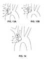
- FIGS. 13A and 13Billustrate alternative distal sheath and distal shaft portions of an exemplary filter system.
- FIG. 14illustrates a portion of an exemplary system including a distal shaft and a distal sheath.
- FIGS. 15A-15Dillustrate alternative embodiments of the coupling of the distal shaft and distal sheath.
- FIG. 16illustrates an exemplary embodiment of a filter system in which the distal sheath is biased to a curved configuration.
- FIG. 17illustrates a portion of an alternative filter system.
- FIGS. 18A and 18Billustrate an exemplary proximal filter.
- FIGS. 19A-22Billustrate exemplary proximal filters.
- FIGS. 23A-23Fillustrate exemplary distal filters.
- FIGS. 24A-24Cillustrate exemplary embodiments in which the system includes at least one distal filter positioning, or stabilizing, anchor.
- FIGS. 25A-25Dillustrate an exemplary embodiment of coupling a distal filter to a docking wire inside of the subject.
- FIGS. 26A-26Gillustrate an exemplary method of preparing an exemplary distal filter assembly for use.
- FIGS. 27A and 27Billustrate an exemplary embodiment in which a guiding member, secured to a distal filter before introduction into the subject is loaded into an articulatable distal sheath.
- FIGS. 28A-28Eillustrate an exemplary distal filter assembly in collapsed and expanded configurations.
- FIGS. 29A-29Eillustrate a portion of an exemplary filter system with a lower delivery and insertion profile.
- FIGS. 30A and 30Billustrate a portion of an exemplary filter system.
- FIGS. 31A-31Cillustrate an exemplary over-the-wire routing system that includes a separate distal port for a dedicated guidewire.
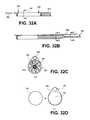
- FIGS. 32A-32Eillustrate an exemplary routing system which includes a rapid-exchange guidewire delivery.
- FIGS. 33-35illustrate exemplary handle portions of the blood filter systems.
- the disclosurerelates generally to intravascular blood filters used to capture foreign particles.
- the blood filteris a dual-filter system to trap foreign bodies to prevent them from traveling into the subject's right and left common carotid arteries.
- the filter systems described hereincan, however, be used to trap particles in other blood vessels within a subject, and they can also be used outside of the vasculature.
- the systems described hereinare generally adapted to be delivered percutaneously to a target location within a subject, but they can be delivered in any suitable way, and need not be limited to minimally-invasive procedures.
- the filter systems described hereinare used to protect the cerebral vasculature against embolisms and other foreign bodies entering the bloodstream during a cardiac valve replacement or repair procedure.
- the system described hereinenters the aorta from the brachiocephalic artery. Once in the aortic space, there is a need to immediately navigate a 180 degree turn into the left common carotid artery. In gaining entry into the aorta from the brachial cephalic artery, use of prior art catheter devices 1 will tend to hug the outer edge of the vessel 2 , as shown in FIG. 1 .
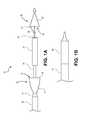
- FIGS. 1A and 1Billustrate a portion of an exemplary filter system.
- Filter system 10includes proximal sheath 12 , proximal shaft 14 coupled to expandable proximal filter 16 , distal shaft 18 coupled to distal articulatable sheath 20 , distal filter 22 , and guiding member 24 .
- FIG. 1Aillustrates proximal filter 16 and distal filter 22 in expanded configurations.
- FIG. 1Billustrates the system in a delivery configuration, in which proximal filter 16 (not seen in FIG. 1B ) is in a collapsed configuration constrained within proximal sheath 12 , while distal filter 22 is in a collapsed configuration constrained within distal articulatable sheath 20 .
- FIG. 1Cis a sectional view of partial system 10 from FIG. 1B .
- Proximal shaft 14is co-axial with proximal sheath 12 , and proximal region 26 of proximal filter 16 is secured to proximal shaft 14 .
- proximal filter 16is disposed within proximal sheath 12 and is disposed distally relative to proximal shaft 14 .
- Proximal sheath 12is axially (distally and proximally) movable relative to proximal shaft 14 and proximal filter 16 .
- System 10also includes distal sheath 20 secured to a distal region of distal shaft 18 .
- Distal shaft 18is co-axial with proximal shaft 14 and proximal sheath 12 .
- Distal sheath 20 and distal shaft 18secured to one another, are axially movable relative to proximal sheath 12 , proximal shaft 14 and proximal filter 16 .
- System 10also includes distal filter 22 carried by guiding member 24 .
- distal filter 22is in a collapsed configuration within distal sheath 22 .
- Guiding member 24is coaxial with distal sheath 20 and distal shaft 18 as well as proximal sheath 12 and proximal shaft 14 .
- Guiding member 24is axially movable relative to distal sheath 20 and distal shaft 18 as well as proximal sheath 12 and proximal shaft 14 .
- Proximal sheath 12 , distal sheath 20 , and guiding member 24are each adapted to be independently moved axially relative to one other. That is, proximal sheath 12 , distal sheath 20 , and guiding member 24 are adapted for independent axial translation relative to each of the other two components.
- proximal filter 16includes support element or frame 15 and filter element 17
- distal filter 22includes support element 21 and filter element 23
- the support elementsgenerally provide expansion support to the filter elements in their respective expanded configurations, while the filter elements are adapted to filter fluid, such as blood, and trap particles flowing therethrough.
- the expansion supportsare adapted to engage the wall of the lumen in which they are expanded.
- the filter elementshave pores therein that are sized to allow the blood to flow therethrough, but are small enough to prevent unwanted foreign particles from passing therethrough. The foreign particles are therefore trapped by and within the filter elements.
- filter element 17is formed of a polyurethane film mounted to frame 15 , as shown in FIGS. 1D and 1E .
- Film element 17can measure about 0.0030 inches to about 0.0003 inches in thickness.
- Filter element 17has through holes 27 to allow fluid to pass and will resist the embolic material within the fluid. These holes can be circular, square, triangular or other geometric shapes. In the embodiment as shown in FIG. 1D , an equilateral triangular shape would restrict a part larger than an inscribed circle but have an area for fluid flow nearly twice as large making the shape more efficient in filtration verses fluid volume. It is understood that similar shapes such as squares and slots would provide a similar geometric advantage.
- Frame element 15can be constructed of a shape memory material such as Nitinol, stainless steel or MP35N or a polymer that has suitable material properties.
- Frame element 15could take the form of a round wire or could also be of a rectangular or elliptical shape to preserve a smaller delivery profile.
- frame element 15is of Nitinol wire where the hoop is created from a straight piece of wire and shape set into a frame where two straight legs run longitudinally along the delivery system and create a circular distal portion onto which the filter film will be mounted.
- the circular portionmay have a radiopaque marking such as a small coil of gold or platinum iridium for visualization under fluoroscopy.
- the shape of frame element 15 and filter element 17are of an oblique truncated cone having a non-uniform or unequal length around and along the length of the conical filter 16 .
- the filter 16would have a larger opening diameter and a reduced ending diameter.
- the larger opening diametercould measure about 15-20 mm in diameter and have a length of about 30-50 mm. Varying size filters would allow treatment of variable patient vessel sizes.
- the material of the filter elementis a smooth textured surface that is folded or contracted into a small delivery catheter by means of tension or compression into a lumen.
- a reinforcement fabric 29may be added to or embedded in the filter to accommodate stresses placed on the filter material by means of the tension or compression applied. This will also reduce the stretching that may occur during delivery and retraction of filter element 17 .
- This reinforcement material 29could be a polymer or metallic weave to add additional localized strength. This material could be imbedded into the polyurethane film to reduce its thickness.
- this imbedded materialcould be polyester weave with a pore size of about 100 microns and a thickness of about 0.002 inches and mounted to a portion of the filter near the longitudinal frame elements where the tensile forces act upon the frame and filter material to expose and retract the filter from its delivery system. While such an embodiment of the filter elements has been described for convenience with reference to proximal filter element 17 , it is understood that distal filter element 23 could similarly take such form or forms.
- proximal filter 16has a generally distally-facing opening 13
- distal filter 22has a generally proximally-facing opening 19 .
- the filterscan be thought of as facing opposite directions.
- the distal sheathis adapted to be steered, or bent, relative to the proximal sheath and the proximal filter. As the distal sheath is steered, the relative directions in which the openings face will be adjusted. Regardless of the degree to which the distal sheath is steered, the filters are still considered to having openings facing opposite directions.
- the distal sheathcould be steered to have a 180 degree bend, in which case the filters would have openings facing in substantially the same direction.
- the directions of the filter openingsare therefore described if the system were to assume a substantially straightened configuration, an example of which is shown in FIG. 1A .
- Proximal filter element 17tapers down in the proximal direction from support element 15
- distal filter element 23tapers down in the distal direction from support element 21 .
- a fluidsuch as blood, flows through the opening and passes through the pores in the filter elements, while the filter elements are adapted to trap foreign particles therein and prevent their passage to a location downstream to the filters.
- the filter poresare between about 1 micron and 1000 microns (1 mm).
- the pore sizecan be larger, however, depending on the location of the filter within the subject and the type of particulate being trapped in the filter.
- the filtersare secured to separate system components.
- proximal filter 16is secured to proximal shaft 14
- distal filter 22is secured to guiding member 24 .
- the filtersare secured to independently-actuatable components. This allows the filters to be independently controlled.
- the filtersare collapsed within two different tubular members in their collapsed configurations.
- proximal filter 16is collapsed within proximal sheath 12
- distal filter 22is collapsed within distal sheath 20 .
- the filtersare axially-spaced from one another.
- distal filter 22is distally-spaced relative to proximal filter 16 .
- the distal sheath and the proximal sheathhave substantially the same outer diameter (see, e.g., FIGS. 1B and 1C ).
- the sheath portion of the systemtherefore has a substantially constant outer diameter, which can ease the delivery of the system through the patient's body and increase the safety of the delivery.
- distal and proximal sheaths 20 and 12have substantially the same outer diameter, both of which have larger outer diameters than the proximal shaft 14 .
- Proximal shaft 14has a larger outer diameter than distal shaft 18 , wherein distal shaft 18 is disposed within proximal shaft 14 .
- Guiding member 24has a smaller diameter than distal shaft 18 .
- the proximal and distal sheathshave an outer diameter of 6 French (F).
- the sheathshave different outer diameters.
- the proximal sheathcan have a size of 6 F, while the distal sheath has a size of 5 F.
- the proximal sheathis 5 F and the distal sheath is 4 F.
- a distal sheath with a smaller outer diameter than the proximal sheathreduces the delivery profile of the system and can ease delivery.
- the filter systemis advanced into the subject through an incision made in the subject's right radial artery.
- a medical instrumentis advanced through a subject's femoral artery, which is larger than the right radial artery.
- a delivery catheter used in femoral artery access procedureshas a larger outer diameter than would be allowed in a filter system advanced through a radial artery.
- the filter systemis advanced from the right radial artery into the aorta via the brachiocephalic trunk.
- the radial arteryhas the smallest diameter of the vessels through which the system is advanced.
- the radial arterytherefore limits the size of the system that can be advanced into the subject when the radial artery is the access point.
- the outer diameters of the systems described herein, when advanced into the subject via a radial artery,are therefore smaller than the outer diameters of the guiding catheters (or sheaths) typically used when access is gained via a femoral artery.
- FIG. 6Aillustrates a portion of a filter delivery system in a delivery configuration.
- the system's delivery configurationgenerally refers to the configuration when both filters are in collapsed configurations within the system.
- FIG. 6Billustrates that that the distal articulating sheath is independently movable with 3 degrees of freedom relative to the proximal sheath and proximal filter.
- proximal sheath 60 and distal sheath 62are coupled together at coupling 61 .
- Coupling 61can be a variety of mechanisms to couple proximal sheath 60 to distal sheath 62 .
- coupling 61can be an interference fit, a friction fit, a spline fitting, or any other type of suitable coupling between the two sheaths.
- the components shown in FIG. 6Bmove as a unit.
- proximal sheath 60 , proximal shaft 64 , proximal filter 66 , distal shaft 68 , and the distal filter(not shown but within distal sheath 62 ) will rotate and translate axially (in the proximal or distal direction) as a unit.
- proximal sheath 60is retracted to allow proximal filter 66 to expand, as shown in FIG.
- distal sheath 62can be independently rotated (“R”), steered (“S”), or translated axially T (either in the proximal “P” direction or distal “D” direction).
- the distal sheaththerefore has 3 independent degrees of freedom: axial translation, rotation, and steering.
- the adaptation to have 3 independent degrees of freedomis advantageous when positioning the distal sheath in a target location, details of which are described below.
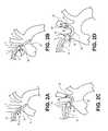
- FIGS. 2A-2Dillustrate a merely exemplary embodiment of a method of using any of the filter systems described herein.
- System 10 from FIGS. 1A-1Cis shown in the embodiment in FIGS. 2A-2D .
- System 10is advanced into the subject's right radial artery through an incision in the right arm.
- the systemis advanced through the right subclavian artery and into the brachiocephalic trunk 11 , and a portion of the system is positioned within aorta 9 as can be seen in FIG. 2A (although that which is shown in FIG. 2A is not intended to be limiting).
- Proximal sheath 12is retracted proximally to allow proximal filter support element 15 to expand to an expanded configuration against the wall of the brachiocephalic trunk 11 , as is shown in FIG. 2B .
- Proximal filter element 17is secured either directly or indirectly to support element 15 , and is therefore reconfigured to the configuration shown in FIG. 2B .
- the position of distal sheath 20can be substantially maintained while proximal sheath 12 is retracted proximally.
- the proximal filterfilters blood traveling through the brachiocephalic artery 11 , and therefore filters blood traveling into the right common carotid artery 7 .
- the expanded proximal filteris therefore in position to prevent foreign particles from traveling into the right common carotid artery 7 and into the cerebral vasculature.
- Distal sheath 20is then steered, or bent, and distal end 26 of distal sheath 20 is advanced into the left common carotid artery 13 , as shown in FIG. 2C .
- Guiding member 24is thereafter advanced distally relative to distal sheath 20 , allowing the distal support element to expand from a collapsed configuration against the wall of the left common carotid artery 13 as shown in FIG. 2D .
- the distal filter elementis also reconfigured into the configuration shown in FIG. 2D .
- Once expanded, the distal filterfilters blood traveling through the left common carotid artery 13 .
- the distal filteris therefore in position to trap foreign particles and prevent them from traveling into the cerebral vasculature.
- an optional medical procedurecan then take place, such as a replacement heart valve procedure. Any plaque dislodged during the heart valve replacement procedure that enters into the brachiocephalic trunk or the left common carotid artery will be trapped in the filters.
- distal filter 22is first retrieved back within distal sheath 20 to the collapsed configuration.
- guiding member 24is retracted proximally relative to distal sheath 20 .
- This relative axial movementcauses distal sheath 20 to engage strut 28 and begin to move strut 28 towards guiding member 24 .
- Support element 21which is coupled to strut 28 , begins to collapse upon the collapse of strut 28 .
- Filter element 23therefore begins to collapse as well.
- Distal sheath 20is then steered into the configuration shown in FIG. 2B , and proximal sheath is then advanced distally relative to proximal filter 16 . This causes proximal filter 16 to collapse around distal shaft 18 , trapping any particles within the collapsed proximal filter.
- Proximal sheath 12continues to be moved distally towards distal sheath 20 until in the position shown in FIG. 2A . The entire system 10 can then be removed from the subject.
- An exemplary advantage of the systems described hereinis that the delivery and retrieval system are integrated into the same catheter that stays in place during the procedure. Unloading and loading of different catheters, sheaths, or other components is therefore unnecessary. Having a system that performs both delivery and retrieval functions also reduces procedural complexity, time, and fluoroscopy exposure time.
- FIGS. 7A-7Billustrate a perspective view and sectional view, respectively, of a portion of an exemplary filter system.
- the systemincludes distal shaft 30 and distal articulatable sheath 34 , coupled via coupler 32 .
- FIG. 7Bshows the sectional view of plane A.
- Distal sheath 34includes steering element 38 extending down the length of the sheath and within the sheath, which is shown as a pullwire.
- the pullwirecan be, for example without limitation, stainless steel, MP35N®, or any type of cable.
- Distal sheath 34also includes spine element 36 , which is shown extending down the length of the sheath on substantially the opposite side of the sheath from steering element 38 .
- Spine element 36can be, for example without limitation, a ribbon or round wire.
- Spine element 36can be made from, for example, stainless steel or nitinol. Spine element 36 provides axial stiffness upon the application of an actuating force applied to steering element 38 , allowing sheath 34 to be steered toward configuration 40 , as shown in phantom in FIG. 7A .
- FIG. 7Cshows an alternative embodiment in which distal sheath 33 has a non-circular cross section. Also shown are spine element 35 and steering element 37 .
- FIGS. 8A-8Cillustrate views of exemplary pullwire 42 that can be incorporated into any distal sheaths described herein.
- Plane B in FIG. 8Bshows a substantially circular cross-sectional shape of pullwire 42 in a proximal portion 44 of the pullwire, while plane C in FIG. 8C shows a flattened cross-sectional shape of distal portion 46 .
- Distal portion 46has a greater width than height.
- the flattened cross-sectional shape of distal portion 46provides for an improved profile, flexibility, and resistance to plastic deformation, which provides for improved straightening.
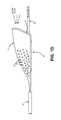
- FIGS. 9, 9A, and 9Bshow an alternative embodiment of distal sheath 48 that includes slots 50 formed therein.
- the slotscan be formed by, for example, grinding, laser cutting or other suitable material removal from distal sheath 48 .
- the characteristics of the slotscan be varied to control the properties of the distal sheath.
- the pitch, width, depth, etc., of the slotscan be modified to control the flexibility, compressibility, torsional responsiveness, etc., of distal sheath 48 .
- the distal sheath 48can be formed from a length of stainless steel hypotubing.
- Transverse slots 50are preferably formed on one side of the hypotubing.
- FIG. 9Ashows a further embodiment of the distal sheath in greater detail.
- distal sheath 48includes a first proximal articulatable hypotube section 49 .
- Articulatable hypotube section 49is fixed to distal shaft 30 (not shown in FIG. 9A ).
- a second distal articulatable section 51is secured to first proximal section 49 .
- Pull wire 38extends from the handle to both distal shaft sections 49 and 51 .
- This embodimentallows for initial curvature of distal sheath proximal section 49 away from the outer vessel wall.
- Distal sheath distal section 51is then articulated to a second curvature in the opposite direction. This second curvature of distal shaft section 51 is adjustable based upon tension or compression loading of the sheath section by pull wire 38 .
- pull wire 38crosses to an opposite side of the inner lumen defined by sections 49 and 51 as it transitions from the first proximal distal sheath section 49 to distal sheath distal section 51 .
- distal sheath proximal section 49would articulate first to initialize a first curve.
- distal sheath distal section 51begins to curve in a direction opposite to the direction of the first curve, due to pull wire 38 crossing the inner diameter of the lumen through distal sheath sections 49 and 51 .
- distal sheath distal section 51can take the form of a shepherd's staff or crook.
- Distal sheath proximal section 49could take the form of a tubular slotted element or a pre-shaped curve that utilizes a memory material such as Nitinol.
- Distal sheath proximal section 49measures about 0.065 inches in diameter with an about 0.053 inch hole through the center and measures about 0.70 inches in length. It is understood that these sizes and proportions will vary depending on the specific application and those listed herein are not intended to be limiting.
- Transverse slots 50can measure about 0.008 inches in width but may vary from about 0.002 inches to about 0.020 inches depending on the specific application and the degree of curvature desired.
- distal shaft proximal section 49is a laser cut tube intended to bend to approximately 45 degrees of curvature when pull wire 38 is fully tensioned.
- This curvaturemay indeed be varied from about 15 degrees to about 60 degrees depending upon the width of slots 50 . It may also bend out-of-plane to access more complex anatomy. This out-of-plane bend could be achieved by revolving the laser cut slots rotationally about the axis of the tube or by bending the tube after the laser cutting of the slots.
- the shapecould also be multi-plane or bidirectional where the tube would bend in multiple directions within the same laser cut tube.
- Distal sheath distal section 51is preferably a selectable curve based upon the anatomy and vessel location relative to one another. This section 51 could also be a portion of the laser cut element or a separate construction where a flat ribbon braid could be utilized. It may also include a stiffening element or bias ribbon to resist permanent deformation. In one embodiment it would have a multitude of flat ribbons staggered in length to create a constant radius of curvature under increased loading.
- FIGS. 10A and 10Billustrate a portion of exemplary distal sheath 52 that is adapted to be multi-directional, and is specifically shown to be bi-directional.
- Distal sheath 52is adapted to be steered towards the configurations 53 and 54 shown in phantom in FIG. 10A .
- FIG. 10Bis a sectional view in plane D, showing spinal element 55 and first and second steering elements 56 disposed on either side of spinal element 55 .
- Steering elements 56can be similar to steering element 38 shown in FIG. 7B .
- the steering elementscan be disposed around the periphery of distal sheath at almost any location.
- the distal sheathincludes radiopaque markers to visualize the distal sheath under fluoroscopy. In some embodiments the distal sheath has radiopaque markers at proximal and distal ends of the sheath to be able to visualize the ends of the sheath.
- an exemplary advantage of the filter systems described hereinis the ability to safely and effectively position the distal sheath.
- the proximal filteris deployed in a first bodily lumen, and the distal filter is deployed in a second bodily lumen different than the first.
- the proximal filteris deployed in the brachiocephalic trunk and the distal filter is deployed in a left common carotid artery. While both vessels extend from the aortic arch, the position of the vessel openings along the aortic arch varies from patient-to-patient. That is, the distance between the vessel openings can vary from patient to patient.
- FIGS. 11A-11Cillustrate merely exemplary anatomical variations that can exist.
- FIG. 11Ais a top view (i.e., in the superior-to-inferior direction) of aorta 70 , showing relative positions of brachiocephalic trunk opening 72 , left common carotid artery opening 74 , and left subclavian opening 76 .
- FIG. 11Ais a top view (i.e., in the superior-to-inferior direction) of aorta 70 , showing relative positions of brachiocephalic trunk opening 72 , left common carotid artery opening 74 , and left subclavian opening 76 .
- FIG. 11Ais a top view (i.e., in the superior-to-inferior direction) of aorta 70 , showing relative positions of brachiocephalic trunk opening 72 , left common carotid artery opening 74 , and left subclavian opening 76 .
- FIG. 11Bis a side sectional view of aortic 78 illustrating the relative angles at which brachiocephalic trunk 80 , left common carotid artery 82 , and left subclavian artery 84 can extend from aorta 78 .
- FIG. 11Cis a side sectional view of aorta 86 , showing vessel 88 extending from aorta 86 at an angle. Any or all of the vessels extending from aorta 86 could be oriented in this manner relative to the aorta.
- 11D and 11Eillustrate that the angle of the turn required upon exiting the brachiocephalic trunk 92 / 100 and entering the left common carotid artery 94 / 102 can vary from patient to patient. Due to the patient-to-patient variability between the position of the vessels and their relative orientations, a greater amount of control of the distal sheath increases the likelihood that the distal filter will be positioned safely and effectively. For example, a sheath that only has the ability to independently perform one or two of rotation, steering, and axial translation may not be adequately adapted to properly and safely position the distal filter in the left common carotid artery. All three degrees of independent motion as provided to the distal sheaths described herein provide important clinical advantages. Typically, but without intending to be limiting, a subject's brachiocephalic trunk and left carotid artery are spaced relatively close together and are either substantially parallel or tightly acute (see, e.g., Figure BE).
- FIGS. 12A and 12Billustrates an exemplary curvature of a distal sheath to help position the distal filter properly in the left common carotid artery.
- FIGS. 12A and 12Bonly a portion of the system is shown for clarity, but it can be assumed that a proximal filter is included, and in this example has been expanded in brachiocephalic trunk 111 .
- Distal shaft 110is coupled to steerable distal sheath 112 .
- Distal sheath 112is steered into the configuration shown in FIG. 12B .
- distal sheath 112The bend created in distal sheath 112 , and therefore the relative orientations of distal sheath 112 and left common carotid artery 113 , allow for the distal filter to be advanced from distal sheath 112 into a proper position in left common carotid 113 .
- the configuration of distal sheath 114 shown in phantom in FIG. 12Aillustrates how a certain bend created in the distal sheath can orient the distal sheath in such a way that the distal filter will be advanced directly into the wall of the left common carotid (depending on the subject's anatomy), which can injure the wall and prevent the distal filter from being properly deployed.
- a general U-shaped curve(shown in phantom in FIG. 12A ) may not be optimal for steering and accessing the left common carotid artery from the brachiocephalic trunk.
- the distal sheathis adapted to have a preset curved configuration.
- the preset configurationcan have, for example, a preset radius of curvature (or preset radii of curvature at different points along the distal sheath).
- continued articulation of the steering elementcan change the configuration of the distal sheath until is assumes the preset configuration.
- the distal sheathcan comprise a slotted tube with a spine extending along the length of the distal sheath.
- the distal sheathUpon actuation of the steering component, the distal sheath will bend until the portions of the distal sheath that define the slots engage, thus limiting the degree of the bend of the distal sheath.
- the curvecan be preset into a configuration that increases the likelihood that the distal filter will, when advanced from the distal sheath, be properly positioned within the left common carotid artery.
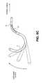
- FIGS. 13A and 13Billustrate alternative distal sheath and distal shaft portions of an exemplary filter system.
- FIGS. 13A and 13Bonly show distal shaft 120 and distal sheath 122 for clarity, but the system also includes a proximal filter (not shown but has been deployed in brachiocephalic trunk).
- the distal shaft/distal sheath combinationhas a general S-bend configuration, with distal shaft 120 including a first bend 124 in a first direction, and distal sheath 122 configured to assume bend 126 in a second direction, wherein the first and second bends form the general S-bend configuration.
- FIG. 13A and 13Billustrate alternative distal sheath and distal shaft portions of an exemplary filter system.
- FIGS. 13A and 13Bonly show distal shaft 120 and distal sheath 122 for clarity, but the system also includes a proximal filter (not shown but has been deployed in brachiocephalic trunk).
- FIGS. 13A and 13Bshows distal sheath 122 pulled back in the proximal direction relative to the proximal filter to seat the curved distal sheath against the bend. This both helps secure the distal sheath in place as well as reduces the cross sectional volume of the filter system that is disposed with the aorta.
- the distal shaft and distal sheath combination shown in FIGS. 13A and 13Bcan be incorporated into any of the filter systems described herein.
- FIGS. 2A-2D, 13A, 13B, 14, 1, 3, 4 and 5Exemplary embodiments of the delivery and deployment of a multi-filter embolic protection apparatus will now be described with reference to FIGS. 2A-2D, 13A, 13B, 14, 1, 3, 4 and 5 . More particularly, the delivery and deployment will be described with reference to placement of the filter system in the brachiocephalic and left common carotid arteries.
- the preferred access for the delivery of the multi-filter system 10is from the right radial or right brachial artery.
- the systemis then advanced through the right subclavian artery to a position within the brachiocephalic artery 11 .
- proximal filter 16may be deployed within into expanding engagement with the inner lining of brachiocephalic artery 11 .
- proximal filter 16protects both the brachiocephalic artery 11 and the right common carotid artery 7 against emboli and other foreign bodies in the bloodstream.
- Entry into the aortic spaceis then accomplished by further advancement of the system from the brachiocephalic trunk.
- the filter systemwill tend to hug the outer portion of the brachiocephalic trunk as shown in FIG. 4 .
- Initial tensioning of pull wire 38causes distal sheath 48 to move the catheter-based filter system off the wall of the brachiocephalic artery just before the ostium or entrance into the aorta, as shown in FIG. 4 .
- a curve directed away from this outer wallwill allow additional space for the distal portion of the distal sheath to curve into the left common carotid artery, as shown in FIG. 5 .
- the width of slots 50will determine the amount of bending allowed by the tube when tension is applied via pull wire 38 .
- a narrow width slotwould allow for limited bending where a wider slot would allow for additional bending due to the gap or space removed from the tube.
- a fixed shape or curvemay be obtained when all slots are compressed and touching one another. Additional features such as chevrons may be cut into the tube to increase the strength of the tube when compressed. Theses chevrons would limit the ability of the tube to flex out of the preferred plane due to torsional loading.
- Other means of forming slotscould be obtained with conventional techniques such as chemical etching, welding of individual elements, mechanical forming, metal injection molding or other conventional methods.
- the distal sheathis further tensioned to adjust the curvature of the distal shaft distal section 51 , as shown in FIG. 9B .
- the amount of deflectionis determined by the operator of the system based on the particular patient anatomy.
- a cathetercould be external force applications to the catheter and the vessel wall such as a protruding ribbon or wire from the catheter wall to force the catheter shaft to a preferred position within the vessel. Flaring a radial element from the catheter central axis could also position the catheter shaft to one side of the vessel wall. Yet another means would be to have a pull wire external to the catheter shaft exiting at one portion and reattaching at a more distal portion where a tension in the wire would bend or curve the catheter at a variable rate in relation to the tension applied.
- This multi-direction and variable curvature of the distal sheathallows the operator to easily direct the filter system, or more particularly, the distal sheath section thereof, into a select vessel such as the left common carotid artery or the left innominate artery.
- the filter systemallows the operator to access the left common carotid artery without the need to separately place a guidewire in the left common carotid artery.
- the clinical variations of these vesselsare an important reason for the operator to have a system that can access differing locations and angulations between the vessels.
- the filter systems described hereinwill provide the physician complete control when attempting to access these vessels.
- the handlecan be manipulated by pulling it and the filter system into the bifurcation leaving the aortic vessel clear of obstruction for additional catheterizations, an example of which is shown in FIG. 12B .
- distal filter 22can be advanced through proximal shaft 14 and distal shaft 18 into expanding engagement with left common carotid artery 13 .
- FIG. 14illustrates a portion of an exemplary system including distal shaft 130 and distal sheath 132 .
- Distal sheathis adapted to be able to be steered into what can be generally considered an S-bend configuration, a shepherd's staff configuration, or a crook configuration, comprised of first bend 131 and second bend 133 in opposite directions.
- rotational orb 134defined by the outer surface of the distal sheath as distal shaft 130 is rotated at least 360 degrees in the direction of the arrows shown in FIG. 14 .
- a typical aortais generally in the range from about 24 mm to about 30 mm in diameter
- the radius of curvature and the first bend in the S-bendcan be specified to create a rotational orb that can reside within the aorta (as shown in FIG. 14 ), resulting in minimal interference with the vessel wall and at the same time potentially optimize access into the left common carotid artery.
- the rotational orb created by the rotation of distal shaft 110is significantly larger, increasing the risk of interference with the vessel wall and potentially decreasing the access into the left common carotid artery.
- the diameter of the rotation orb for a distal sheathis less than about 25 mm.
- distal sheath 112in some embodiments, includes a non-steerable distal section 121 , an intermediate steerable section 119 , and a proximal non-steerable section 117 .
- distal sheathWhen the distal sheath is actuated to be steered, only steerable portion 119 bends into a different configuration. That is, the non-steerable portions retain substantially straight configurations. The distal non-steerable portion remains straight, which can allow the distal filter to be advanced into a proper position in the left common carotid artery.
- FIG. 12Ashows distal sheath 112 in a bent configuration
- the distal sheathis also positioned within the lumen of the aorta. In this position, the distal sheath can interfere with any other medical device or instrument that is being advanced through the aorta.
- delivery device 116with a replacement aortic valve disposed therein, is delivered through the aorta as shown in FIG. 12B . If components of the filter system are disposed within the aorta during this time, delivery device 116 and the filter system can hit each other, potentially damaging either or both systems.
- the delivery device 116can also dislodge one or both filters if they are in the expanded configurations.
- the filter systemcan additionally prevent the delivery device 116 from being advanced through the aorta.
- distal sheath 112(and distal shaft 110 ) is translated in the proximal direction relative to the proximal filter (which in this embodiment has already been expanded but is not shown), as is shown in FIG. 12B .
- Distal sheath 112is pulled back until the inner curvature of distal sheath 112 is seated snugly with the vasculature 15 disposed between the brachiocephalic trunk 111 and the left common carotid artery 113 .
- This additional seating stephelps secure the distal sheath in place within the subject, as well as minimize the amount of the filter system present in the aortic arch.
- This additional seating stepcan be incorporated into any of the methods described herein, and is an exemplary advantage of having a distal sheath that has three degrees of independent motion relative to the proximal filter. The combination of independent rotation, steering, and axial translation can be clinically significant to ensure the distal filter is properly positioned in the lumen, as well as making sure the filter system does not interfere with any other medical devices being delivered to the general area inside the subject.
- distal sheathwhen in the position shown in FIG. 11C , will act as a protection element against any other medical instruments being delivered through the aorta (e.g., delivery device 116 ). Even if delivery device 116 were advanced such that it did engage distal sheath 112 , distal sheath 112 is seated securely against tissue 15 , thus preventing distal sheath 112 from being dislodged. Additionally, distal sheath 112 is stronger than, for example, a wire positioned within the aorta, which can easily be dislodged when hit by delivery device 16 .
- FIGS. 15A-15Dillustrate alternative embodiments of the coupling of the distal shaft and distal sheath.
- distal shaft 140is secured to distal sheath 142 by coupler 144 .
- Shaft 140has a low profile to allow for the collapse of the proximal filter (see FIG. 1C ).
- Shaft 140also has column strength to allow for axial translation, has sufficient torque transmission properties, and is flexible.
- the shaftcan have a support structure therein, such as braided stainless steel.
- the shaftcan comprise polyimide, Polyether ether ketone (PEEK), Nylon, Pebax, etc.
- FIG. 15Billustrates an alternative embodiment showing tubular element 146 , distal shaft 148 , and distal sheath 150 .
- Tubular element 146can be a hypotube made from stainless steel, nitinol, etc.
- FIG. 15Cillustrates an exemplary embodiment that includes distal shaft 152 , traction member 154 , and distal sheath 156 . Traction member 154 is coupled to shaft 152 and shaft 152 is disposed therein. Traction member 154 couples to shaft 152 for torquebility, deliverability, and deployment. Traction member 154 can be, for example without limitation, a soft silicone material, polyurethane, or texture (e.g., polyimide, braid, etc.).
- FIG. 15Dshows an alternative embodiment in which the system includes bushing 162 disposed over distal shaft 158 , wherein distal shaft 158 is adapted to rotate within bushing 162 .
- the systemalso includes stop 160 secured to distal shaft 158 to substantially maintain the axial position of bushing 162 .
- distal sheath 164can be rotated relative to the proximal sheath and the proximal filter when the distal sheath and proximal sheath are in the delivery configuration (see FIG. 1B ).
- FIG. 16illustrates an exemplary embodiment of filter system 170 in which distal sheath 172 is biased to a curved configuration 174 .
- the biased curved configurationis adapted to facilitate placement, delivery, and securing at least the distal filter.
- the distal sheathis biased to a configuration that positions the distal end of the distal sheath towards the left common carotid artery.
- FIG. 17illustrates a portion of an exemplary filter system and its method of use.
- FIG. 17shows a system and portion of deployment similar to that shown in FIG. 2D , but distal sheath 182 has been retracted proximally relative to guiding member 190 and distal filter 186 .
- Distal sheath 182has been retracted substantially from the aortic arch and is substantially disposed with the brachiocephalic trunk.
- Guiding member 190can have preset curve 188 adapted to closely mimic the anatomical curve between the brachiocephalic trunk and the left common carotid artery, thus minimizing the amount of the system that is disposed within the aorta.
- distal sheath 182has been retracted proximally relative to proximal filter 180 .
- FIG. 18Ais a perspective view of a portion of an exemplary embodiment of a filter system, while FIG. 18B is a close-up view of a portion of the system shown in FIG. 18A .
- the distal sheath and the distal filterare not shown in FIGS. 18A and 18B for clarity.
- the systemincludes proximal filter 200 coupled to proximal shaft 202 , and push rod 206 coupled to proximal shaft 202 .
- a portion of proximal sheath 204is shown in FIG. 18A in a retracted position, allowing proximal filter 200 to expand to an expanded configuration. Only a portion of proximal sheath 204 is shown, but it generally extends proximally similar to push rod 206 .
- proximal shaft 202The proximal end of proximal shaft 202 is beveled and defines an aspiration lumen 216 , which is adapted to receive an aspirator (not shown) to apply a vacuum to aspirate debris captured within distally facing proximal filter 200 .
- Push rod 206extends proximally within proximal sheath 204 and is coupled to an actuation system outside of the subject, examples of which are described below. Push rod 206 takes up less space inside proximal sheath 204 than proximal shaft 202 , providing a lower profile.
- the systemalso includes proximal seal 214 disposed on the outer surface of proximal shaft 202 and adapted to engage the inner surface of the proximal sheath.
- Proximal seal 214prevents bodily fluids, such as blood, from entering the space between proximal sheath 204 and proximal shaft 202 , thus preventing bodily fluids from passing proximally into the filter system.
- the proximal sealcan be, for example without limitation, a molded polymer.
- the proximal sealcan also be machined as part of the proximal shaft, such that they are not considered two separate components.
- the push rodis about 0.015 inches in diameter, and is grade 304 stainless steel grade.
- the proximal shaftcan be, for example without limitation, an extruded or molded plastic, a hypotube (e.g., stainless steel), machined plastic, metal, etc.
- Proximal filter 200includes filter material 208 , which comprises pores adapted to allow blood to pass therethrough, while debris does not pass through the pores and is captured within the filter material.
- Proximal filter 200also includes strut 210 that extends from proximal shaft 202 to expansion support 212 .
- Expansion support 212has a generally annular shape but that is not intended to be limiting.
- Proximal filter 200also has a leading portion 220 and a trailing portion 222 . Leading portion 220 generally extends further distally than trailing portion 222 to give filter 200 a generally canted configuration relative to the proximal shaft. The canted design provides for decreased radial stiffness and a better collapsed profile.
- Strut 210 and expansion support 212generally provide support for filter 200 when in the expanded configuration, as shown in FIG. 18A .
- FIGS. 19A-19Cillustrate exemplary embodiments of proximal filters and proximal shafts that can be incorporated into any of the systems herein.
- filter 230has flared end 232 for improved filter-wall opposition.
- FIG. 19Bshows proximal shaft 244 substantially co-axial with vessel 246 in which filter 240 is expanded. Vessel 246 and shaft 244 have common axis 242 .
- FIG. 19Cillustrates longitudinal axis 254 of shaft 256 not co-axial with axis 252 of lumen 258 in which filter 250 is expanded.
- FIGS. 20A and 20Billustrate an exemplary embodiment including proximal filter 260 coupled to proximal shaft 262 .
- Filter 260includes filter material 264 , including slack material region 268 adapted to allow the filter to collapse easier.
- Filter 260is also shown with at least one strut 270 secured to shaft 262 , and expansion support 266 .
- filter 260includes seal 274 , radiopaque coil 276 (e.g., platinum), and support wire 278 (e.g., nitinol wire). Any of the features in this embodiment can be included in any of the filter systems described herein.
- FIG. 21illustrates an exemplary embodiment of a proximal filter.
- Proximal filter 280is coupled to proximal shaft 282 .
- Proximal filter 280includes struts 286 extending from proximal shaft 282 to strut restraint 288 , which is adapted to slide axially over distal shaft 284 .
- Proximal filter 280also includes filter material 290 , with pores therein, that extends from proximal shaft 282 to a location axially between proximal shaft 282 and strut restraint 288 . Debris can pass through struts 286 and become trapped within filter material 290 .
- struts 286When proximal filter 280 is collapsed within a proximal sheath (not shown), struts 286 elongate and move radially inward (towards distal shaft 284 ). Strut restraint 288 is adapted to move distally over distal shaft 284 to allow the struts to move radially inward and extend a greater length along distal shaft 284 .
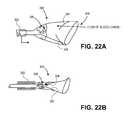
- FIGS. 22A and 22Billustrate an exemplary embodiment of a proximal filter that can be incorporated into any filter system described herein.
- the systemincludes proximal filter 300 and proximal sheath 302 , shown in a retracted position in FIG. 22A .
- Proximal filter 300includes valve elements 304 in an open configuration in FIG. 22A . When valve elements 304 are in the open configuration, foreign particles 306 can pass through opening 308 and through the valve and become trapped in proximal filter 300 , as is shown in FIG. 22A .
- proximal sheath 302is advanced distally relative to proximal filter 300 . As the filter begins to collapse, the valve elements are brought closer towards one another and into a closed configuration, as shown in FIG. 22B . The closed valve prevents extrusion of debris during the recapture process.
- FIG. 23Aillustrates a portion of an exemplary filter system.
- the systemincludes guiding member 340 (distal sheath not shown), strut 342 , expansion support 344 , and filter element 346 .
- Strut 342is secured directly to guiding member 340 and strut 342 is secured either directly or indirectly to expansion support 344 .
- Filter material 346is secured to expansion support 344 .
- Distal end 348 of filter material 346is secured to guiding member 340 .
- FIG. 23Billustrates a portion of an exemplary filter system.
- the systemincludes guiding element 350 , strut support 352 secured to guiding element 350 , strut 354 , expansion support 356 , and filter material 358 .
- Strut support 352can be secured to guiding element 350 in any suitable manner (e.g., bonding), and strut 354 can be secured to strut support 352 in any suitable manner.
- FIG. 23Cillustrates a portion of an exemplary filter system.
- the systemincludes guiding element 360 , strut support 362 secured to guiding element 360 , strut 364 , expansion support 366 , and filter material 368 .
- Expansion support 366is adapted to be disposed at an angle relative to the longitudinal axis of guiding member 360 when the distal filter is in the expanded configuration.
- Expansion support 366includes trailing portion 362 and leading portion 361 .
- Strut 364is secured to expansion support 366 at or near leading portion 361 .
- FIG. 23Dillustrates an exemplary embodiment that includes guiding member 370 , strut support 372 , strut 374 , expansion support 376 , and filter material 378 .
- Expansion support 376includes leading portion 373 , and trailing portion 371 , wherein strut 374 is secured to expansion element 376 at or near trailing portion 371 . Expansion support 376 is disposed at an angle relative to the longitudinal axis of guiding member 370 when the distal filter is in the expanded configuration.
- FIG. 23Eillustrates an exemplary embodiment of a distal filter in an expanded configuration.
- Guiding member 380is secured to strut support 382
- the filterincludes a plurality of struts 384 secured to strut support 382 and to expansion support 386 .
- Filter material 388is secured to expansion support 386 . While four struts are shown, the distal filter may include any number of struts.
- FIG. 23Fillustrates an exemplary embodiment of a distal filter in an expanded configuration.
- Proximal stop 392 and distal stop 394are secured to guiding member 390 .
- the distal filterincludes tubular member 396 that is axially slideable over guiding member 390 , but is restricted in both directions by stops 392 and 394 .
- Strut 398is secured to slideable member 396 and to expansion support 393 .
- Filter material 395is secured to slideable member 396 . If member 396 slides axially relative to guiding member 390 , filter material 395 moves as well.
- Member 396is also adapted to rotate in the direction “R” relative to guiding member 390 .
- the distal filteris therefore adapted to independently move axially and rotationally, limited in axial translation by stops 392 and 394 .
- the distal filteris therefore adapted such that bumping of the guiding member or the distal sheath will not disrupt the distal filter opposition, positioning, or effectiveness.
- FIGS. 24A-24Cillustrate exemplary embodiments in which the system includes at least one distal filter positioning, or stabilizing, anchor.
- the positioning anchor(s)can help position the distal anchor in a proper position and/or orientation within a bodily lumen.
- the systemincludes distal filter 400 and positioning anchor 402 .
- Anchor 402includes expandable stent 404 and expandable supports 406 . Supports 406 and filter 400 are both secured to the guiding member.
- Anchor 402can be any suitable type of expandable anchor, such as, for example without limitation, stent 404 .
- Anchor 402can be self-expandable, expandable by an expansion mechanism, or a combination thereof.
- stent 404can alternatively be expanded by an expansion balloon.
- Anchor 402is disposed proximal to filter 400 .
- FIG. 24Billustrates an embodiment in which the system includes first and second anchors 412 and 414 , one of which is proximal to filter 410 , while the other is distal to filter 410 .
- FIG. 24Cillustrates an embodiment in which anchor 422 is distal relative to filter 420 .
- the distal filteris coupled, or secured, to a guiding member that has already been advanced to a location within the subject.
- the distal filteris therefore coupled to the guiding member after the distal filter has been advanced into the subject, rather than when the filter is outside of the subject.
- the guiding membercan be moved (e.g., axially translated) to control the movement of the distal filter.
- the guiding memberhas a first locking element adapted to engage a second locking element on the distal filter assembly such that movement of the guiding member moves the distal filter in a first direction.
- the distal filter assemblyhas a third locking element that is adapted to engage the first locking element of the guiding member such that movement of the guiding member in a second direction causes the distal filter to move with the guiding member in the second direction.
- the guiding membercan therefore be locked to the distal filter such that movement of the guiding member in a first and a second direction will move the distal filter in the first and second directions.
- FIGS. 25A-25Dillustrate an exemplary embodiment of coupling the distal filter to a docking wire inside of the subject, wherein the docking wire is subsequently used to control the movement of the distal filter relative to the distal sheath.
- guide catheter 440has been advanced through the subject until the distal end is in or near the brachiocephalic trunk 441 .
- a docking wirecomprising a wire 445 , locking element 442 , and tip 444 , has been advanced through guide catheter 440 , either alone, or optionally after guiding wire 446 has been advanced into position. Guiding wire 446 can be used to assist in advancing the docking wire through guide catheter 440 .
- the docking wirehas been advanced from the distal end of guide catheter 440 .
- guide catheter 440and if guiding wire 446 is used, are removed from the subject, leaving the docking wire in place within the subject, as shown in FIG. 25B .
- the filter systemincluding proximal sheath 448 with a proximal filter in a collapsed configuration therein (not shown), distal sheath 450 , with a distal filter assembly (not shown) partially disposed therein, is advanced over wire 445 until a locking portion of the distal filter (not shown but described in detail below) engages locking element 442 .
- the distal filter assemblywill thereafter move (e.g., axially) with the docking wire.
- Proximal sheath 448is retracted to allow proximal filter 454 to expand (see FIG. 25D ).
- Distal sheath 450is then actuated (e.g., bent, rotated, and/or translated axially) until it is in the position shown in FIG. 25D .
- a straightened configuration of the distal sheathis shown in phantom in FIG. 25D , prior to bending, proximal movement, and/or bending.
- the docking wireis then advanced distally relative to distal sheath 450 , which advances distal filter 456 from distal sheath 450 , allowing distal filter 456 to expand inside the left common carotid artery, as shown in FIG. 25D .
- FIGS. 26A-26Dillustrate an exemplary method of preparing an exemplary distal filter assembly for use.
- FIG. 26Aillustrates a portion of the filter system including proximal sheath 470 , proximal filter 472 is an expanded configuration, distal shaft 474 , and articulatable distal sheath 476 .
- Distal filter assembly 478includes an elongate member 480 defining a lumen therein. Elongate member 480 is coupled to distal tip 490 .
- Strut 484is secured both to strut support 482 , which is secured to elongate member 480 , and expansion support 486 .
- Filter element 488has pores therein and is secured to expansion support 486 and elongate member 480 .
- loading mandrel 492is advanced through distal tip 490 and elongate member 480 and pushed against distal tip 490 until distal filter assembly 478 is disposed within distal sheath 476 , as shown in FIG. 26C .
- Distal tip 490 of the filter assemblyremains substantially distal to distal sheath 476 , and is secured to the distal end of distal sheath 476 .
- Distal tip 490 and distal sheath 476can be secured together by a frictional fit or other type of suitable fit that disengages as described below.
- Loading mandrel 492is then removed from the distal filter and distal sheath assembly, as shown in FIG. 26D .
- FIG. 26Eillustrates docking wire 500 including wire 502 , lock element 504 , and distal tip 506 .
- Docking wire 500is first advanced to a desired position within the subject, such as is shown in FIG. 25B .
- the assembly from FIG. 26Dis then advanced over docking wire, wherein distal tip 490 is first advanced over the docking wire.
- distal tip 490 of the distal filter assemblyincludes first locking elements 510 , shown as barbs.
- the docking wire locking element 504pushes locks 510 outward in the direction of the arrows in FIG. 26F .
- lock element 504engages with lock elements 510 , and the lock element 504 pushes the distal filter assembly in the distal direction. In this manner the distal filter can be distally advanced relative to the distal sheath to expand the distal filter. Additionally, when the docking wire is retracted proximally, locking element 504 engages the distal end 512 of elongate member 480 and pulls the distal filter in the proximal direction. This is done to retrieve and/or recollapse the distal filter back into the distal sheath after it has been expanded.
- FIGS. 27A and 27Billustrate an exemplary embodiment in which guiding member 540 , secured to distal filter 530 before introduction into the subject is loaded into articulatable distal sheath 524 .
- the systemalso includes proximal filter 520 , proximal sheath 522 , and distal shaft 526 .
- FIG. 27Bshows the system in a delivery configuration in which both filters are collapsed.
- FIGS. 28A-28Eillustrate an exemplary distal filter assembly in collapsed and expanded configurations.
- distal filter assembly 550includes a distal frame, which includes strut 554 and expansion support 555 .
- the distal frameis secured to floating anchor 558 , which is adapted to slide axially on elongate member 564 between distal stop 560 and proximal stop 562 , as illustrated by the arrows in FIG. 28A .
- the distal filter assemblyalso includes membrane 552 , which has pores therein and is secured at its distal end to elongate member 564 .
- the distal filter assemblyis secured to a guiding member, which includes wire 566 and soft distal tip 568 .
- the guiding membercan be, for example, similar to the docking wire shown in FIGS. 26A-26E above, and can be secured to the distal filter assembly as described in that embodiment.
- the floating anchor 558allows filter membrane 552 to return to a neutral, or at-rest, state when expanded, as shown in FIG. 28A .
- the neutral deployed stateallows for optimal filter frame orientation and vessel apposition.
- floating anchor 558is roughly mid-way between distal stop 560 and proximal stop 562 , but this is not intended to be a limiting position when the distal filter is in a neutral state.
- FIG. 28Billustrates the distal filter being sheathed into distal sheath 572 .
- the distal filteris collapsed from an expanded configuration (see FIG. 28A ) towards a collapsed configuration (see FIG. 28C ).
- distal sheath 572is moving distally relative to the distal filter.
- the distal end of the distal sheath 572engages with strut 554 as it is advanced distally, causing the distal end of strut 554 to moves towards elongate member 564 .
- Strut 554can be thought of as collapsing towards elongate member 564 from the configuration shown in FIG. 28A .
- Distal sheath 172continues to be advanced distally relative to the distal filter (or the distal filter is pulled proximally relative to the distal sheath, or a combination of both) until the distal filter is collapsed within distal sheath 172 , as is shown in FIG. 28C .
- Filter membrane 552is bunched to some degree when the filter is in the configuration shown in FIG. 28C .
- guiding member 566is advanced distally relative to the distal sheath (or the distal sheath is moved proximally relative to the filter).
- the distal portions of filter membrane 552 and expansion support 555are deployed first, as is shown in FIG. 28D .
- Tension in the filter membraneprevents wadding and binding during the deployment.
- expansion support 555 and strut 554are able to self-expand to an at-rest configuration, as shown in FIG. 28E .
- Floating anchor 558is pulled in the distal direction from the position shown in FIG. 28D to the position shown in FIG. 28E due to the expansion of strut 554 .
- FIGS. 29A-29Eillustrate a portion of an exemplary filter system with a lower delivery and insertion profile.
- the systemincludes proximal sheath 604 with a larger outer diameter than distal sheath 602 .
- proximal sheath 604has a 6 F outer diameter
- distal sheath 602has a 5 F outer diameter.
- a guiding member including distal tip 606is disposed within the distal sheath and the proximal sheath.
- FIG. 29Billustrates tear-away introducer 608 , with receiving opening 610 and distal end 612 . Introducer is first positioned within a subject with receiving opening 610 remaining outside the patient. As shown in FIG.
- the smaller diameter distal sheathis first advanced through the receiving opening of introducer 608 until the distal end of the distal sheath is disposed distal relative to the distal end of the introducer.
- the introduceris then split apart and removed from the subject, as shown in FIG. 29D .
- the filter systemcan then be advanced distally through the subject.
- the introducercan be a 5 F introducer, which reduces the insertion and delivery profile of the system.
- FIGS. 30A and 30Billustrate an exemplary embodiment similar to that which is shown in FIGS. 27A and 27B .
- the filter systemshows distal filter 650 and proximal filter 644 in expanded configurations. Proximal sheath 642 has been retracted to allow proximal filter 644 to expand. Distal filter, which is secured to guiding member 648 , are both advanced distally relative to distal articulating sheath 640 .
- the filter systemdoes not have a dedicated guidewire that is part of the system, but distal sheath 640 is adapted to be rotated and steered to guide the system to a target location within the subject.
- FIGS. 31A-31Cillustrate an exemplary over-the-wire routing system that includes a separate distal port for a dedicated guidewire.
- a portion of the systemis shown in FIG. 31B , including distal articulating sheath 662 and proximal sheath 660 (the filters are collapsed therein).
- FIG. 31Ais a highlighted view of a distal region of FIG. 31B , showing guidewire entry port 666 near the distal end 664 of distal sheath 662 .
- FIG. 31Cis a sectional view through plane A of distal sheath 662 , showing guidewire lumen 672 , spine element 678 , distal filter lumen 674 , and steering element 676 (shown as a pullwire).
- Guidewire lumen 672 and distal filter lumen 674are bi-axial along a portion of distal sheath, but in region 670 guidewire lumen 672 transitions from within the wall of distal sheath 662 to being co-axial with proximal sheath 660 .
- a guidewireis first delivered to a target location within the subject.
- the guidewirecan be any type of guidewire, such as a 0.014 inch coronary wire.
- the filter systemis then tracked over the guidewire to a desired position within the subject. Once the system is in place, the guidewire is withdrawn from the subject, or it can be left in place.
- the proximal and distal filterscan then be deployed as described in any of the embodiments herein.
- FIGS. 32A-32Eillustrate an exemplary routing system which includes a rapid-exchange guidewire delivery.
- the systemincludes distal articulating sheath 680 with guidewire entry port 684 and guidewire exit port 686 .
- the systemalso includes proximal sheath 682 , a distal filter secured to a guiding member (collapsed within distal sheath 680 ), and a proximal filter (collapsed within proximal sheath 682 ).
- guidewire 688is advanced into position within the patient, the proximal end of guidewire 688 is advanced into guidewire entry port 684 .
- Distal sheath(along with the proximal sheath) is tracked over guidewire 688 until guidewire 688 exits distal sheath 680 at guidewire exit port 686 .
- Including a guidewire exit port near the entry portallows for only a portion of the guidewire to be within the sheath(s), eliminating the need to have a long segment of guidewire extending proximally from the subject's entry point.
- the proximal end of the guidewire and the proximal sheathcan both be handled.
- FIG. 32Bshows guidewire 688 extending through the guidewire lumen in the distal sheath and extending proximally from exit port 686 .
- Guidewire 688extends adjacent proximal sheath 682 proximal to exit port 686 .
- portion 690 of proximal sheath 682has a diameter larger than portion 692 to accommodate the proximal filter therein.
- Portion 692has a smaller diameter for easier passage of the proximal sheath and guidewire.
- FIG. 32Cshows a sectional view through plane A, with guidewire 688 exterior and adjacent to proximal sheath 682 .
- Proximal filter 694is in a collapsed configuration within proximal sheath 682 , and guiding member 696 is secured to a distal filter, both of which are disposed within distal shaft 698 .
- FIG. 32Dshows relative cross-sections of exemplary introducer 700 , and distal sheath 680 through plane CC.
- Distal sheath 680includes guidewire lumen 702 and distal filter lumen 704 .
- introducer 700is 6 F, with an inner diameter of about 0.082 inches.
- the distal sheathcan have a guidewire lumen of about 0.014 inches and distal filter lumen diameter of about 0.077 inches.
- the introducer sheathcan tent due to the size and shape of the distal sheath. There may be some slight resistance to the advancement of the distal sheath through the introducer sheath.
- 32Eshows a sectional view through plane B, and also illustrates the insertion through introducer 700 . Due to the smaller diameter of portion 692 of proximal sheath 682 , guidewire 688 and proximal sheath 682 more easily fit through introducer 700 than the distal sheath and portion of the proximal sheath distal to portion 692 . Introducer is 6 F, while proximal sheath is 5 F. Guidewire 688 is a 0.014 inch diameter guidewire. The smaller diameter proximal portion 692 of proximal sheath 682 allows for optimal sheath and guidewire movement with the introducer sheath.
- FIG. 33illustrates a portion of an exemplary filter system.
- the portion shown in FIG. 33is generally the portion of the system that remains external to the subject and is used to control the delivery and actuation of system components.
- Proximal sheath 710is fixedly coupled to proximal sheath hub 712 , which when advanced distally will sheath the proximal filter (as described herein), and when retracted proximally will allow the proximal filter to expand.
- the actuation, or control, portionalso includes handle 716 , which is secured to proximal shaft 714 . When handle 716 is maintained axially in position, the position of the proximal filter is axially maintained.
- the actuation portionalso includes distal sheath actuator 722 , which includes handle 723 and deflection control 720 .
- Distal sheath actuator 722is secured to distal shaft 718 .
- the distal articulating sheathis adapted to have three independent degrees of motion relative to the proximal sheath and proximal filter: rotation, axially translation (i.e., proximal and distal), and deflection, and distal sheath actuator 722 is adapted to move distal sheath 718 in the three degrees of motion.
- Distal sheath 718is rotated in the direction shown in FIG. 33 by rotating distal sheath actuator 722 .
- Axial translation of distal sheathoccurs by advancing actuator 722 distally (pushing) or by retracting actuator 722 proximally (pulling).
- Distal sheath 218is deflected by axial movement of deflection control 720 .
- Movement of deflection control 720actuates the pullwire(s) within distal sheath 718 to control the bending of distal sheath 718 .
- guiding member 724which is secured to the distal filter and is axially movable relative to the distal sheath to deploy and collapse the distal filter as described herein.
- the control portionalso includes hemostasis valves 726 , which is this embodiment are rotating.
- FIG. 34illustrates an exemplary 2-piece handle design that can be used with any of the filter systems described herein.
- This 2-piece handle designincludes distal sheath actuator 746 , which includes handle section 748 and deflection control knob 750 .
- Deflection control knob 750 of distal sheath actuator 746is secured to distal shaft 754 .
- Axial movement of distal sheath actuator 746will translate distal shaft 754 either distally or proximally relative to the proximal filter and proximal sheath.
- a pull wire(not shown in FIG. 34 ) is secured to handle section 748 and to the distal articulatable sheath (not shown in FIG. 34 ).
- Axial movement of deflection control knob 750applies tension, or relieves tension depending on the direction of axial movement of deflection control knob 750 , to control the deflection of the distal articulatable sheath relative to the proximal filter and proximal sheath 744 , which has been described herein.
- Rotation of distal sheath actuator 746will rotate the distal sheath relative to the proximal filter and proximal sheath.
- the handlealso includes housing 740 , in which proximal sheath hub 742 is disposed.
- Proximal sheath hub 742is secured to proximal sheath 744 and is adapted to be moved axially to control the axial movement of proximal sheath 744 .
- FIG. 35illustrates another exemplary embodiment of a handle that can be used with any of the filter systems described herein.
- the handleis of a 3-piece design.
- This 3-piece handle designcomprises a first proximal piece which includes distal sheath actuator 761 , which includes handle section 763 and deflection control knob 765 .
- Deflection control knob 765 of distal sheath actuator 761is secured to distal shaft 767 .
- Axial movement of distal sheath actuator 761will translate distal shaft 767 either distally or proximally relative to the proximal filter and proximal sheath.
- a pull wire(not shown in FIG. 35 ) is secured to handle section 763 and to the distal articulatable sheath (not shown in FIG.
- Axial movement of deflection control knob 765applies tension, or relieves tension depending on the direction of axial movement of deflection control knob 765 , to control the deflection of the distal articulatable sheath relative to the proximal filter and proximal sheath 769 .
- Rotation of distal sheath actuator 761will rotate the distal sheath relative to the proximal filter and proximal sheath 769 .
- the handle designfurther includes a second piece comprising central section 760 which is secured to proximal shaft 771 .
- a third distal piece of this handle designincludes housing 762 . Housing 762 is secured to proximal sheath 769 .
- Housing 762is adapted to move axially with respect to central section 760 . With central section 760 held fixed in position, axial movement of housing 762 translates to axial movement of proximal sheath 769 relative to proximal shaft 771 . In this manner, proximal filter 773 is either released from the confines of proximal sheath 769 into expandable engagement within the vessel or, depending on direction of movement of housing 762 , is collapsed back into proximal sheath 769 .
Landscapes
- Health & Medical Sciences (AREA)
- Life Sciences & Earth Sciences (AREA)
- Engineering & Computer Science (AREA)
- Public Health (AREA)
- Veterinary Medicine (AREA)
- Biomedical Technology (AREA)
- Heart & Thoracic Surgery (AREA)
- Animal Behavior & Ethology (AREA)
- General Health & Medical Sciences (AREA)
- Vascular Medicine (AREA)
- Transplantation (AREA)
- Cardiology (AREA)
- Oral & Maxillofacial Surgery (AREA)
- Mechanical Engineering (AREA)
- Biophysics (AREA)
- Pulmonology (AREA)
- Anesthesiology (AREA)
- Hematology (AREA)
- Surgical Instruments (AREA)
Abstract
Description
Claims (48)
Priority Applications (5)
| Application Number | Priority Date | Filing Date | Title |
|---|---|---|---|
| US12/871,708US9326843B2 (en) | 2009-01-16 | 2010-08-30 | Intravascular blood filters and methods of use |
| US15/080,345US20170042658A1 (en) | 2009-01-16 | 2016-03-24 | Intravascular blood filters and methods of use |
| US16/144,468US11284986B2 (en) | 2009-01-16 | 2018-09-27 | Intravascular blood filters and methods of use |
| US17/691,727US12201507B2 (en) | 2009-01-16 | 2022-03-10 | Intravascular blood filters and methods of use |
| US19/032,336US20250241740A1 (en) | 2009-01-16 | 2025-01-20 | Intravascular blood filters and methods of use |
Applications Claiming Priority (6)
| Application Number | Priority Date | Filing Date | Title |
|---|---|---|---|
| US14514909P | 2009-01-16 | 2009-01-16 | |
| US24441809P | 2009-09-21 | 2009-09-21 | |
| US12/689,997US8372108B2 (en) | 2009-01-16 | 2010-01-19 | Intravascular blood filter |
| US33489310P | 2010-05-14 | 2010-05-14 | |
| US34897910P | 2010-05-27 | 2010-05-27 | |
| US12/871,708US9326843B2 (en) | 2009-01-16 | 2010-08-30 | Intravascular blood filters and methods of use |
Related Parent Applications (1)
| Application Number | Title | Priority Date | Filing Date |
|---|---|---|---|
| US12/689,997Continuation-In-PartUS8372108B2 (en) | 2009-01-16 | 2010-01-19 | Intravascular blood filter |
Related Child Applications (1)
| Application Number | Title | Priority Date | Filing Date |
|---|---|---|---|
| US15/080,345ContinuationUS20170042658A1 (en) | 2009-01-16 | 2016-03-24 | Intravascular blood filters and methods of use |
Publications (2)
| Publication Number | Publication Date |
|---|---|
| US20110282379A1 US20110282379A1 (en) | 2011-11-17 |
| US9326843B2true US9326843B2 (en) | 2016-05-03 |
Family
ID=44912411
Family Applications (5)
| Application Number | Title | Priority Date | Filing Date |
|---|---|---|---|
| US12/871,708Active2031-05-15US9326843B2 (en) | 2009-01-16 | 2010-08-30 | Intravascular blood filters and methods of use |
| US15/080,345AbandonedUS20170042658A1 (en) | 2009-01-16 | 2016-03-24 | Intravascular blood filters and methods of use |
| US16/144,468Active2030-07-10US11284986B2 (en) | 2009-01-16 | 2018-09-27 | Intravascular blood filters and methods of use |
| US17/691,727Active2031-05-31US12201507B2 (en) | 2009-01-16 | 2022-03-10 | Intravascular blood filters and methods of use |
| US19/032,336PendingUS20250241740A1 (en) | 2009-01-16 | 2025-01-20 | Intravascular blood filters and methods of use |
Family Applications After (4)
| Application Number | Title | Priority Date | Filing Date |
|---|---|---|---|
| US15/080,345AbandonedUS20170042658A1 (en) | 2009-01-16 | 2016-03-24 | Intravascular blood filters and methods of use |
| US16/144,468Active2030-07-10US11284986B2 (en) | 2009-01-16 | 2018-09-27 | Intravascular blood filters and methods of use |
| US17/691,727Active2031-05-31US12201507B2 (en) | 2009-01-16 | 2022-03-10 | Intravascular blood filters and methods of use |
| US19/032,336PendingUS20250241740A1 (en) | 2009-01-16 | 2025-01-20 | Intravascular blood filters and methods of use |
Country Status (1)
| Country | Link |
|---|---|
| US (5) | US9326843B2 (en) |
Cited By (15)
| Publication number | Priority date | Publication date | Assignee | Title |
|---|---|---|---|---|
| US9566144B2 (en) | 2015-04-22 | 2017-02-14 | Claret Medical, Inc. | Vascular filters, deflectors, and methods |
| US9636205B2 (en) | 2009-01-16 | 2017-05-02 | Claret Medical, Inc. | Intravascular blood filters and methods of use |
| US9943395B2 (en) | 2010-12-30 | 2018-04-17 | Claret Medical, Inc. | Deflectable intravascular filter |
| US10130458B2 (en) | 2009-07-27 | 2018-11-20 | Claret Medical, Inc. | Dual endovascular filter and methods of use |
| US10314600B2 (en) | 2012-05-21 | 2019-06-11 | Noha, Llc | Clot removal device and method of using same |
| US10743977B2 (en) | 2009-01-16 | 2020-08-18 | Boston Scientific Scimed, Inc. | Intravascular blood filter |
| US10932799B2 (en) | 2016-11-14 | 2021-03-02 | Covidien Lp | Embolic protection system including multiple filter bodies |
| US11154390B2 (en) | 2017-12-19 | 2021-10-26 | Claret Medical, Inc. | Systems for protection of the cerebral vasculature during a cardiac procedure |
| US11191630B2 (en) | 2017-10-27 | 2021-12-07 | Claret Medical, Inc. | Systems and methods for protecting the cerebral vasculature |
| US11284986B2 (en) | 2009-01-16 | 2022-03-29 | Claret Medical, Inc. | Intravascular blood filters and methods of use |
| US11337790B2 (en) | 2017-02-22 | 2022-05-24 | Boston Scientific Scimed, Inc. | Systems and methods for protecting the cerebral vasculature |
| US11351023B2 (en) | 2018-08-21 | 2022-06-07 | Claret Medical, Inc. | Systems and methods for protecting the cerebral vasculature |
| US11439491B2 (en) | 2018-04-26 | 2022-09-13 | Claret Medical, Inc. | Systems and methods for protecting the cerebral vasculature |
| US11607301B2 (en) | 2009-01-16 | 2023-03-21 | Boston Scientific Scimed, Inc. | Intravascular blood filters and methods of use |
| US12150851B2 (en) | 2010-12-30 | 2024-11-26 | Claret Medical, Inc. | Method of isolating the cerebral circulation during a cardiac procedure |
Families Citing this family (35)
| Publication number | Priority date | Publication date | Assignee | Title |
|---|---|---|---|---|
| US9827084B2 (en) | 2007-10-26 | 2017-11-28 | Embolitech, Llc | Intravascular guidewire filter system for pulmonary embolism protection and embolism removal or maceration |
| US8518073B2 (en) | 2009-01-29 | 2013-08-27 | Claret Medical, Inc. | Illuminated intravascular blood filter |
| JP5951955B2 (en)* | 2011-10-17 | 2016-07-13 | 株式会社東海メディカルプロダクツ | Filter device for embolization substance capture |
| WO2013063124A1 (en) | 2011-10-25 | 2013-05-02 | Boston Scientific Scimed, Inc. | Embolic debris deflector |
| US8968354B2 (en) | 2011-10-26 | 2015-03-03 | Boston Scientific Scimed, Inc. | Extended protection embolic filter |
| US10548706B2 (en) | 2012-01-13 | 2020-02-04 | Volcano Corporation | Retrieval snare device and method |
| US10426501B2 (en) | 2012-01-13 | 2019-10-01 | Crux Biomedical, Inc. | Retrieval snare device and method |
| EP2805515B1 (en) | 2012-01-17 | 2022-10-05 | Lumen Biomedical, Inc. | Aortic arch filtration system for carotid artery protection |
| US10213288B2 (en) | 2012-03-06 | 2019-02-26 | Crux Biomedical, Inc. | Distal protection filter |
| WO2013142201A1 (en)* | 2012-03-21 | 2013-09-26 | Nexeon Medsystems, Inc. | Apparatus and methods for filtering emboli during percutaneous aortic valve replacement and repair procedures with filtration system coupled in-situ to distal end of sheath |
| US9861464B2 (en) | 2012-04-13 | 2018-01-09 | Regents Of The University Of Minnesota | Cardio-embolic stroke prevention |
| US20140031857A1 (en)* | 2012-07-25 | 2014-01-30 | Boston Scientific Scimed, Inc. | Embolic protection filter for transcatheter aortic valve replacement and uses thereof |
| US10307240B2 (en) | 2012-12-11 | 2019-06-04 | Alan Zajarias | Methods and apparatus for capturing embolic debris during endovascular procedures |
| US10973618B2 (en)* | 2013-03-01 | 2021-04-13 | St. Jude Medical, Cardiology Division, Inc. | Embolic protection device |
| US9968433B2 (en) | 2013-03-01 | 2018-05-15 | St. Jude Medical, Cardiology Division, Inc. | Embolic protection pass through tube |
| US9888993B2 (en) | 2013-03-01 | 2018-02-13 | St. Jude Medical, Cardiology Division, Inc. | Embolic protection device |
| US10350098B2 (en) | 2013-12-20 | 2019-07-16 | Volcano Corporation | Devices and methods for controlled endoluminal filter deployment |
| US20170106170A1 (en)* | 2015-10-19 | 2017-04-20 | Biocardia, Inc. | Multi-Directional Steerable Catheter |
| CN108778187A (en) | 2015-12-30 | 2018-11-09 | 管道医疗技术股份有限公司 | tethered mitral valve leaflets |
| US11284911B2 (en)* | 2016-07-22 | 2022-03-29 | Hesham Morsi | Central clot stabilizer and manipulator |
| US10653862B2 (en)* | 2016-11-07 | 2020-05-19 | Edwards Lifesciences Corporation | Apparatus for the introduction and manipulation of multiple telescoping catheters |
| US10925731B2 (en) | 2016-12-30 | 2021-02-23 | Pipeline Medical Technologies, Inc. | Method and apparatus for transvascular implantation of neo chordae tendinae |
| US11083580B2 (en) | 2016-12-30 | 2021-08-10 | Pipeline Medical Technologies, Inc. | Method of securing a leaflet anchor to a mitral valve leaflet |
| US9877833B1 (en) | 2016-12-30 | 2018-01-30 | Pipeline Medical Technologies, Inc. | Method and apparatus for transvascular implantation of neo chordae tendinae |
| EP3585305B1 (en) | 2017-02-23 | 2025-07-30 | Boston Scientific Scimed, Inc. | Medical drain device |
| US11007347B2 (en)* | 2017-04-26 | 2021-05-18 | Biosense Webster (Israel) Ltd. | Deflectable insertion tool |
| US10933214B2 (en) | 2017-04-26 | 2021-03-02 | Biosense Webster (Israel) Ltd. | Method for producing a deflectable insertion tool |
| GB2576334B (en) | 2018-08-14 | 2021-06-02 | Mokita Medical Gmbh | Embolic protection systems and devices |
| JP2022513793A (en) | 2018-12-12 | 2022-02-09 | パイプライン メディカル テクノロジーズ, インコーポレイテッド | Methods and equipment for mitral valve chordae tendineae repair |
| US11707351B2 (en) | 2019-08-19 | 2023-07-25 | Encompass Technologies, Inc. | Embolic protection and access system |
| US11992406B2 (en)* | 2019-09-09 | 2024-05-28 | St. Jude Medical, Cardiology Division, Inc. | Multi-step deployment to improve TAVR implant stability |
| US20210145561A1 (en)* | 2019-11-20 | 2021-05-20 | Bedrosian Global, Llc | System for cerebral embolic protection during heart valve procedure |
| JP7701390B2 (en) | 2020-06-17 | 2025-07-01 | パイプライン メディカル テクノロジーズ, インコーポレイテッド | Methods and devices for mitral valve chordae repair |
| AU2022335448A1 (en)* | 2021-08-27 | 2024-04-11 | Jacob CHMIELEWSKI | Thrombectomy capture system |
| CN115444613A (en)* | 2022-07-12 | 2022-12-09 | 上海申淇医疗科技有限公司 | Cerebral embolism protection device and system with distal cerebral embolism protection device |
Citations (177)
| Publication number | Priority date | Publication date | Assignee | Title |
|---|---|---|---|---|
| US3472230A (en) | 1966-12-19 | 1969-10-14 | Fogarty T J | Umbrella catheter |
| US4619246A (en) | 1984-05-23 | 1986-10-28 | William Cook, Europe A/S | Collapsible filter basket |
| US4630609A (en) | 1981-05-14 | 1986-12-23 | Thomas J. Fogarty | Dilatation catheter method and apparatus |
| US4650466A (en) | 1985-11-01 | 1987-03-17 | Angiobrade Partners | Angioplasty device |
| US4706671A (en) | 1985-05-02 | 1987-11-17 | Weinrib Harry P | Catheter with coiled tip |
| US4723549A (en) | 1986-09-18 | 1988-02-09 | Wholey Mark H | Method and apparatus for dilating blood vessels |
| US4873978A (en) | 1987-12-04 | 1989-10-17 | Robert Ginsburg | Device and method for emboli retrieval |
| US5108419A (en) | 1990-08-16 | 1992-04-28 | Evi Corporation | Endovascular filter and method for use thereof |
| US5192286A (en) | 1991-07-26 | 1993-03-09 | Regents Of The University Of California | Method and device for retrieving materials from body lumens |
| US5329923A (en)* | 1991-02-15 | 1994-07-19 | Lundquist Ingemar H | Torquable catheter |
| US5348545A (en) | 1990-08-21 | 1994-09-20 | Advanced Cardiovascular Systems, Inc. | Guiding catheter for the right coronary artery |
| US5381782A (en) | 1992-01-09 | 1995-01-17 | Spectrum Medsystems Corporation | Bi-directional and multi-directional miniscopes |
| US5395327A (en) | 1990-02-02 | 1995-03-07 | Ep Technologies, Inc. | Catheter steering mechanism |
| US5613980A (en) | 1994-12-22 | 1997-03-25 | Chauhan; Tusharsindhu C. | Bifurcated catheter system and method |
| US5624430A (en) | 1994-11-28 | 1997-04-29 | Eton; Darwin | Magnetic device to assist transcorporeal guidewire placement |
| US5662671A (en) | 1996-07-17 | 1997-09-02 | Embol-X, Inc. | Atherectomy device having trapping and excising means for removal of plaque from the aorta and other arteries |
| US5707389A (en) | 1995-06-07 | 1998-01-13 | Baxter International Inc. | Side branch occlusion catheter device having integrated endoscope for performing endoscopically visualized occlusion of the side branches of an anatomical passageway |
| US5766151A (en) | 1991-07-16 | 1998-06-16 | Heartport, Inc. | Endovascular system for arresting the heart |
| US5779716A (en) | 1995-10-06 | 1998-07-14 | Metamorphic Surgical Devices, Inc. | Device for removing solid objects from body canals, cavities and organs |
| US5814064A (en) | 1997-03-06 | 1998-09-29 | Scimed Life Systems, Inc. | Distal protection device |
| US5827324A (en) | 1997-03-06 | 1998-10-27 | Scimed Life Systems, Inc. | Distal protection device |
| US5833650A (en) | 1995-06-05 | 1998-11-10 | Percusurge, Inc. | Catheter apparatus and method for treating occluded vessels |
| US5848964A (en) | 1997-06-06 | 1998-12-15 | Samuels; Shaun Lawrence Wilkie | Temporary inflatable filter device and method of use |
| US5897819A (en) | 1996-07-10 | 1999-04-27 | Asahi Intecc Co., Ltd. | Process of making a guide wire for a catheter |
| US5897529A (en) | 1997-09-05 | 1999-04-27 | Cordis Webster, Inc. | Steerable deflectable catheter having improved flexibility |
| WO1999023976A1 (en) | 1997-11-07 | 1999-05-20 | Salviac Limited | An embolic protection device |
| US5910154A (en) | 1997-05-08 | 1999-06-08 | Embol-X, Inc. | Percutaneous catheter and guidewire having filter and medical device deployment |
| US5935139A (en) | 1996-05-03 | 1999-08-10 | Boston Scientific Corporation | System for immobilizing or manipulating an object in a tract |
| US5980555A (en) | 1995-11-07 | 1999-11-09 | Embol-X, Inc. | Method of using cannula with associated filter during cardiac surgery |
| US5989281A (en)* | 1995-11-07 | 1999-11-23 | Embol-X, Inc. | Cannula with associated filter and methods of use during cardiac surgery |
| US6045547A (en) | 1998-06-15 | 2000-04-04 | Scimed Life Systems, Inc. | Semi-continuous co-extruded catheter shaft |
| US6080140A (en) | 1998-11-04 | 2000-06-27 | Iowa-India Investments Company, Ltd. | Integral cerebro-vascular access system |
| US6083239A (en) | 1998-11-24 | 2000-07-04 | Embol-X, Inc. | Compliant framework and methods of use |
| US6096053A (en) | 1996-05-03 | 2000-08-01 | Scimed Life Systems, Inc. | Medical retrieval basket |
| US6099534A (en) | 1997-10-01 | 2000-08-08 | Scimed Life Systems, Inc. | Releasable basket |
| US6120494A (en) | 1998-01-23 | 2000-09-19 | Medtronic, Inc. | Method of placing a cannula |
| US6142987A (en) | 1999-08-03 | 2000-11-07 | Scimed Life Systems, Inc. | Guided filter with support wire and methods of use |
| US6152946A (en) | 1998-03-05 | 2000-11-28 | Scimed Life Systems, Inc. | Distal protection device and method |
| US6171328B1 (en) | 1999-11-09 | 2001-01-09 | Embol-X, Inc. | Intravascular catheter filter with interlocking petal design and methods of use |
| US6245088B1 (en) | 1997-07-07 | 2001-06-12 | Samuel R. Lowery | Retrievable umbrella sieve and method of use |
| US6245087B1 (en) | 1999-08-03 | 2001-06-12 | Embol-X, Inc. | Variable expansion frame system for deploying medical devices and methods of use |
| US6264663B1 (en) | 1995-10-06 | 2001-07-24 | Metamorphic Surgical Devices, Llc | Device for removing solid objects from body canals, cavities and organs including an invertable basket |
| US6277138B1 (en) | 1999-08-17 | 2001-08-21 | Scion Cardio-Vascular, Inc. | Filter for embolic material mounted on expandable frame |
| US6290710B1 (en) | 1999-12-29 | 2001-09-18 | Advanced Cardiovascular Systems, Inc. | Embolic protection device |
| US20010041858A1 (en) | 1998-01-23 | 2001-11-15 | Pinaki Ray | Methods and devices for occluding the ascending aorta and maintaining circulation of oxygenated blood in the patient when the patient's heart is arrested |
| US6325815B1 (en) | 1999-09-21 | 2001-12-04 | Microvena Corporation | Temporary vascular filter |
| US6346116B1 (en) | 1999-08-03 | 2002-02-12 | Medtronic Ave, Inc. | Distal protection device |
| US20020026145A1 (en) | 1997-03-06 | 2002-02-28 | Bagaoisan Celso J. | Method and apparatus for emboli containment |
| US6361545B1 (en) | 1997-09-26 | 2002-03-26 | Cardeon Corporation | Perfusion filter catheter |
| US6364900B1 (en) | 1999-07-14 | 2002-04-02 | Richard R. Heuser | Embolism prevention device |
| US6371971B1 (en) | 1999-11-15 | 2002-04-16 | Scimed Life Systems, Inc. | Guidewire filter and methods of use |
| US6383205B1 (en) | 1997-09-30 | 2002-05-07 | Target Therapeutics, Inc. | Mechanical clot treatment device with distal filter |
| US6383174B1 (en) | 1997-08-05 | 2002-05-07 | Scimed Life Systems, Inc. | Detachable aneurysm neck bridge (II) |
| US20020055767A1 (en) | 2000-10-18 | 2002-05-09 | Forde Sean T. | Over-the-wire interlock attachment/detachment mechanism |
| US20020077596A1 (en) | 1997-05-12 | 2002-06-20 | Embol-X, Inc. | Perfusion shunt apparatus and method |
| US20020095170A1 (en) | 2001-01-16 | 2002-07-18 | Krolik Jeff A. | Systems and methods for vascular filter retrieval |
| US20020095172A1 (en) | 1994-07-08 | 2002-07-18 | Microvena Corporation | Method and device for filtering body fluid |
| US6440120B1 (en) | 1998-09-02 | 2002-08-27 | Embol-X, Inc. | Bendable shape-retaining cannula |
| US20020165571A1 (en) | 2000-08-21 | 2002-11-07 | Stephen Hebert | Manipulatable delivery catheter for occlusive devices (ll) |
| US6485502B2 (en) | 2000-03-10 | 2002-11-26 | T. Anthony Don Michael | Vascular embolism prevention device employing filters |
| US6517559B1 (en) | 1999-05-03 | 2003-02-11 | O'connell Paul T. | Blood filter and method for treating vascular disease |
| US6558356B2 (en) | 1999-01-15 | 2003-05-06 | Coaxia, Inc. | Medical device for flow augmentation in patients with occlusive cerebrovascular disease and methods of use |
| US20030100919A1 (en) | 1999-07-30 | 2003-05-29 | Incept Llc | Vascular device for emboli, thrombus and foreign body removal and methods of use |
| US20030130684A1 (en) | 2001-12-21 | 2003-07-10 | Eamon Brady | Support frame for an embolic protection device |
| US6595983B2 (en) | 2000-12-07 | 2003-07-22 | Jan K. Voda | Guide or diagnostic catheter for right coronary artery |
| US20030171770A1 (en) | 2002-03-08 | 2003-09-11 | Kusleika Richard S. | Distal protection devices having controllable wire motion |
| US6620148B1 (en) | 1999-08-04 | 2003-09-16 | Scimed Life Systems, Inc. | Filter flush system and methods of use |
| US6648837B2 (en) | 1999-12-24 | 2003-11-18 | Asahi Intec., Ltd. | Medical guide wire |
| US20040002730A1 (en) | 2002-06-26 | 2004-01-01 | Denison Andy E. | Embolic filtering devices for bifurcated vessels |
| US6676682B1 (en) | 1997-05-08 | 2004-01-13 | Scimed Life Systems, Inc. | Percutaneous catheter and guidewire having filter and medical device deployment capabilities |
| US20040044350A1 (en)* | 1999-04-09 | 2004-03-04 | Evalve, Inc. | Steerable access sheath and methods of use |
| US20040044360A1 (en) | 2002-09-04 | 2004-03-04 | Scimed Life Systems, Inc. | Embolic management filter design |
| US6712834B2 (en)* | 1998-06-16 | 2004-03-30 | Mindguard Ltd. | Implantable blood filtering device |
| WO2004026175A1 (en) | 2002-09-19 | 2004-04-01 | Petrus Besselink | Vascular filter with improved strength and flexibility |
| US20040064092A1 (en) | 1996-05-14 | 2004-04-01 | Ross S. Tsugita | Balloon occlusion device and methods of use |
| US6726701B2 (en) | 1999-05-07 | 2004-04-27 | Salviac Limited | Embolic protection device |
| US6726651B1 (en) | 1999-08-04 | 2004-04-27 | Cardeon Corporation | Method and apparatus for differentially perfusing a patient during cardiopulmonary bypass |
| US20040093015A1 (en) | 2002-08-01 | 2004-05-13 | Ogle Matthew F. | Embolism protection devices |
| US6740061B1 (en) | 2000-07-28 | 2004-05-25 | Ev3 Inc. | Distal protection device |
| DE10049812B4 (en) | 2000-10-09 | 2004-06-03 | Universitätsklinikum Freiburg | Device for filtering out macroscopic particles from the bloodstream during local removal of an aortic valve on the human or animal heart |
| US20040167565A1 (en) | 2003-02-24 | 2004-08-26 | Scimed Life Systems, Inc. | Embolic protection filtering device that can be adapted to be advanced over a guidewire |
| US20040193206A1 (en) | 1997-07-10 | 2004-09-30 | Brent Gerberding | Methods and devices for the treatment of aneurysms |
| US20040215167A1 (en) | 2002-08-27 | 2004-10-28 | Amir Belson | Embolic protection device |
| US20040225321A1 (en) | 2003-05-07 | 2004-11-11 | Scimed Life Systems, Inc. | Filter membrane with increased surface area |
| US6817999B2 (en) | 2002-01-03 | 2004-11-16 | Afx, Inc. | Flexible device for ablation of biological tissue |
| US20040230220A1 (en) | 2003-02-11 | 2004-11-18 | Cook Incorporated | Removable vena cava filter |
| US20040243175A1 (en) | 2001-03-12 | 2004-12-02 | Don Michael T. Anthony | Vascular obstruction removal system and method |
| US6830579B2 (en) | 2001-05-01 | 2004-12-14 | Coaxia, Inc. | Devices and methods for preventing distal embolization using flow reversal and perfusion augmentation within the cerebral vasculature |
| US20040254602A1 (en) | 2003-03-28 | 2004-12-16 | Lehe Cathleen Von | Double ended intravascular medical device |
| US20040254601A1 (en) | 2003-06-12 | 2004-12-16 | Scimed Life Systems, Inc. | Valved embolic protection filter |
| US20050010285A1 (en) | 1999-01-27 | 2005-01-13 | Lambrecht Gregory H. | Cardiac valve procedure methods and devices |
| US6843798B2 (en) | 1999-08-27 | 2005-01-18 | Ev3 Inc. | Slideable vascular filter |
| US20050065397A1 (en)* | 2003-01-15 | 2005-03-24 | Usgi Medical Inc. | Endoluminal tool deployment system |
| US20050080356A1 (en) | 2003-10-14 | 2005-04-14 | Steven Dapolito | Steerable distal protection guidewire and methods of use |
| US6881194B2 (en) | 2001-03-21 | 2005-04-19 | Asahi Intec Co., Ltd. | Wire-stranded medical hollow tube, and a medical guide wire |
| US20050101987A1 (en) | 2003-11-06 | 2005-05-12 | Scimed Life Systems, Inc. | Flattened tip filter wire design |
| US6905490B2 (en) | 1998-03-13 | 2005-06-14 | Gore Enterprise Holdings, Inc. | Apparatus and methods for reducing embolization during treatment of carotid artery disease |
| US6907298B2 (en) | 2002-01-09 | 2005-06-14 | Medtronic, Inc. | Method and apparatus for imparting curves in implantable elongated medical instruments |
| US20050131449A1 (en) | 2003-12-11 | 2005-06-16 | Scimed Life Systems, Inc. | Nose rider improvement for filter exchange and methods of use |
| US20050137696A1 (en) | 2003-12-23 | 2005-06-23 | Sadra Medical | Apparatus and methods for protecting against embolization during endovascular heart valve replacement |
| US20050177132A1 (en)* | 2004-02-09 | 2005-08-11 | Lentz David J. | Catheter articulation segment with alternating cuts |
| US20060015138A1 (en) | 2004-07-19 | 2006-01-19 | Michael Gertner | Emboli diverting devices created by microfabricated means |
| US20060030877A1 (en) | 2002-01-30 | 2006-02-09 | Martinez Lorraine M | Distal filtration devices and methods of use during aortic procedures |
| US20060041188A1 (en) | 2003-03-25 | 2006-02-23 | Dirusso Carlo A | Flexible endoscope |
| US7011094B2 (en) | 2001-03-02 | 2006-03-14 | Emphasys Medical, Inc. | Bronchial flow control devices and methods of use |
| US20060089666A1 (en) | 2001-07-02 | 2006-04-27 | Linder Richard J | Methods, systems, and devices for deploying an embolic protection filter |
| US20060100662A1 (en) | 1997-03-06 | 2006-05-11 | Daniel John M K | Distal protection device and method |
| US20060100658A1 (en)* | 2004-11-09 | 2006-05-11 | Hiroyuki Obana | Interventional guiding sheath system and method of use |
| US20060135961A1 (en) | 2004-12-17 | 2006-06-22 | Biocardia, Inc. | Steerable guide catheters and methods for their use |
| US20060149350A1 (en) | 2003-06-05 | 2006-07-06 | Flowmedica, Inc. | Systems and methods for performing bi-lateral interventions or diagnosis in branched body lumens |
| US20060161241A1 (en) | 2005-01-14 | 2006-07-20 | Denise Barbut | Methods and devices for treating aortic atheroma |
| US7094249B1 (en) | 1997-03-06 | 2006-08-22 | Boston Scientific Scimed, Inc. | Distal protection device and method |
| US20060200191A1 (en) | 1996-05-20 | 2006-09-07 | Gholam-Reza Zadno-Azizi | Method and apparatuses for treating an intravascular occlusion |
| US7115134B2 (en) | 2002-07-22 | 2006-10-03 | Chambers Technology, Llc. | Catheter with flexible tip and shape retention |
| US20060259066A1 (en) | 2005-04-28 | 2006-11-16 | Euteneuer Charles L | Bifurcated artery filter system |
| US7160255B2 (en) | 2001-07-12 | 2007-01-09 | Vahid Saadat | Method and device for sensing and mapping temperature profile of a hollow body organ |
| US7169161B2 (en) | 2001-11-06 | 2007-01-30 | Possis Medical, Inc. | Guidewire having occlusive device and repeatably crimpable proximal end |
| US7169165B2 (en) | 2001-01-16 | 2007-01-30 | Boston Scientific Scimed, Inc. | Rapid exchange sheath for deployment of medical devices and methods of use |
| US7182757B2 (en) | 2003-12-25 | 2007-02-27 | Asahi Intecc Co., Ltd. | Medical guide wire |
| US20070088383A1 (en) | 2005-10-03 | 2007-04-19 | Cook Incorporated | Embolic protection device |
| US20070088244A1 (en) | 2005-10-18 | 2007-04-19 | Biocardia, Inc. | Bio-interventional therapeutic treatments for cardiovascular diseases |
| US7214237B2 (en) | 2001-03-12 | 2007-05-08 | Don Michael T Anthony | Vascular filter with improved strength and flexibility |
| US20070173878A1 (en) | 2006-01-25 | 2007-07-26 | Heuser Richard R | Catheter system for connecting adjacent blood vessels |
| US20070191880A1 (en) | 2004-06-25 | 2007-08-16 | Angiodynamics, Inc. | Retrievable blood clot filter |
| US7278974B2 (en) | 2004-03-15 | 2007-10-09 | Asahi In Tecc Co., Ltd. | Medical guide wire |
| US20070244504A1 (en) | 2002-03-05 | 2007-10-18 | Salviac Limited | Embolic protection system |
| US7313445B2 (en) | 2002-09-26 | 2007-12-25 | Medtronic, Inc. | Medical lead with flexible distal guidewire extension |
| US7323001B2 (en) | 2003-01-30 | 2008-01-29 | Ev3 Inc. | Embolic filters with controlled pore size |
| US20080058860A1 (en) | 1999-07-30 | 2008-03-06 | Incept Llc | Vascular device for emboli and thrombi removal and methods of use |
| US20080065145A1 (en) | 2006-09-11 | 2008-03-13 | Carpenter Judith T | Embolic protection device and method of use |
| US20080125848A1 (en) | 2006-06-30 | 2008-05-29 | Kusleika Richard S | Medical devices with amorphous metals, and methods therefor |
| US20080154153A1 (en) | 2004-08-25 | 2008-06-26 | Heuser Richard R | Multiple-wire systems and methods for ablation of occlusions within blood vessels |
| US7399308B2 (en)* | 1999-02-12 | 2008-07-15 | Cordis Corporation | Vascular filter system |
| WO2008100790A2 (en) | 2007-02-16 | 2008-08-21 | Reverse Medical Corporation | Occlusion device and method of use |
| US20080234722A1 (en) | 2006-06-14 | 2008-09-25 | Possis Medical, Inc. | Inferior vena cava filter on guidewire |
| WO2008113857A2 (en) | 2007-03-20 | 2008-09-25 | Minvasys | Apparatus and methods for stent delivery with embolic protection |
| US20080262442A1 (en) | 2007-04-17 | 2008-10-23 | Carlin Donald B | Connectors for multi fiber optical probes |
| US20080300462A1 (en) | 2007-05-31 | 2008-12-04 | Boston Scientific Scimed, Inc. | Active controlled bending in medical devices |
| US20090024153A1 (en) | 2001-03-12 | 2009-01-22 | Don Michael T Anthony | Vascular filter with improved strength and flexibilty |
| US20090024072A1 (en) | 2007-07-18 | 2009-01-22 | Enrique Criado | Methods and systems for establishing retrograde carotid arterial blood flow |
| US7493154B2 (en) | 2002-10-23 | 2009-02-17 | Medtronic, Inc. | Methods and apparatus for locating body vessels and occlusions in body vessels |
| US20090069840A1 (en) | 2007-09-07 | 2009-03-12 | Crusader Medical Llc | Percutaneous permanent retrievable vascular filter |
| US7559925B2 (en) | 2006-09-15 | 2009-07-14 | Acclarent Inc. | Methods and devices for facilitating visualization in a surgical environment |
| US20090198269A1 (en) | 2005-12-12 | 2009-08-06 | Ralf Hannes | Device for the Removal of Thrombi From Blood Vessels |
| US20090203962A1 (en) | 2008-02-07 | 2009-08-13 | Voyage Medical, Inc. | Stent delivery under direct visualization |
| US20090254172A1 (en) | 2008-04-03 | 2009-10-08 | Grewe David D | Self cleaning devices, systems and methods of use |
| US20090287187A1 (en)* | 2008-05-07 | 2009-11-19 | Guided Delivery Systems Inc. | Deflectable guide |
| US7621904B2 (en)* | 2004-10-21 | 2009-11-24 | Boston Scientific Scimed, Inc. | Catheter with a pre-shaped distal tip |
| US20090326575A1 (en) | 2008-06-23 | 2009-12-31 | Galdonik Jason A | Embolic protection during percutaneous heart valve replacement and similar procedures |
| US20100004633A1 (en) | 2008-07-07 | 2010-01-07 | Voyage Medical, Inc. | Catheter control systems |
| US20100063537A1 (en) | 2006-03-10 | 2010-03-11 | Ev3 Inc. | Embolic protection systems |
| US20100179584A1 (en) | 2006-09-11 | 2010-07-15 | Carpenter Judith T | Methods of diverting embolic debris away from the cerebral circulation |
| US20100179647A1 (en) | 2006-09-11 | 2010-07-15 | Carpenter Judith T | Methods of reducing embolism to cerebral circulation as a consequence of an index cardiac procedure |
| US20100179583A1 (en) | 2006-09-11 | 2010-07-15 | Carpenter Judith T | Methods of deploying and retrieving an embolic diversion device |
| US20100179585A1 (en) | 2006-09-11 | 2010-07-15 | Carpenter Judith T | Embolic deflection device |
| US20100185231A1 (en) | 2009-01-16 | 2010-07-22 | Lashinski Randall T | Intravascular Blood Filter |
| US20100185216A1 (en) | 2008-08-13 | 2010-07-22 | Garrison Michi E | Suture delivery device |
| US20100191276A1 (en) | 2009-01-29 | 2010-07-29 | Lashinski Randall T | Illuminated Intravascular Blood Filter |
| US20100211095A1 (en) | 2006-09-11 | 2010-08-19 | Carpenter Judith T | Embolic Protection Device and Method of Use |
| US20100312268A1 (en) | 2006-11-29 | 2010-12-09 | Amir Belson | Embolic protection device |
| US20100324589A1 (en) | 2006-09-11 | 2010-12-23 | Carpenter Judith T | Embolic deflection device |
| US20110022076A1 (en) | 2009-07-27 | 2011-01-27 | Lashinski Randall T | Dual Endovascular Filter and Methods of Use |
| US20110066221A1 (en) | 2007-11-15 | 2011-03-17 | Endogad Research Pty Limited | Hybrid intraluminal device |
| US7918859B2 (en) | 2006-02-13 | 2011-04-05 | Retro Vascular, Inc. | Recanalizing occluded vessels using controlled antegrade and retrograde tracking |
| WO2011034718A3 (en) | 2009-09-21 | 2011-06-30 | Claret Medical, Inc. | Intravascular blood filters and methods of use |
| US7998104B2 (en) | 2003-11-21 | 2011-08-16 | Silk Road Medical, Inc. | Method and apparatus for treating a carotid artery |
| US8002790B2 (en) | 1999-05-07 | 2011-08-23 | Salviac Limited | Support frame for an embolic protection device |
| US20110282379A1 (en) | 2009-01-16 | 2011-11-17 | Michael Lee | Intravascular Blood Filters and Methods of Use |
| US20120046739A1 (en) | 2010-04-14 | 2012-02-23 | Randolf Von Oepen | Method of delivering a medical device across a plurality of valves |
| US20120095500A1 (en) | 2010-10-14 | 2012-04-19 | Heuser Richard R | Concentric wire embolism protection device |
| US20120172916A1 (en) | 2010-12-30 | 2012-07-05 | Claret Medical, Inc. | Method of Isolating the Cerebral Circulation During a Cardiac Procedure |
| US20120203265A1 (en) | 2010-10-14 | 2012-08-09 | Heuser Richard R | Embolism protection device |
| US20130131714A1 (en) | 2011-11-14 | 2013-05-23 | Boston Scientific Scimed, Inc. | Embolic protection device and methods of making the same |
| EP2658476A1 (en) | 2010-12-30 | 2013-11-06 | Claret Medical, Inc. | Intravascular blood filters and methods of use |
| US20140052170A1 (en) | 2012-08-17 | 2014-02-20 | Richard R. Heuser | Embolism protection device |
| US20140282379A1 (en) | 2011-05-31 | 2014-09-18 | Accenture Global Services Limited | Computer-implemented method, system and computer program product for displaying a user interface component |
| US20150039016A1 (en) | 2012-03-09 | 2015-02-05 | Keystone Heart Ltd. | Device and method for deflecting emboli in an aorta |
Family Cites Families (58)
| Publication number | Priority date | Publication date | Assignee | Title |
|---|---|---|---|---|
| ATE128405T1 (en) | 1990-02-20 | 1995-10-15 | Procter & Gamble | OPEN CAPILLARY CHANNELS STRUCTURE, METHOD FOR MAKING SAME AND EXTRUSION NOZZLE FOR USE THEREIN. |
| US5304131A (en) | 1991-07-15 | 1994-04-19 | Paskar Larry D | Catheter |
| EP0746236B1 (en) | 1993-10-01 | 2003-08-20 | Boston Scientific Corporation | Improved vena cava filter |
| US5680873A (en)* | 1995-03-02 | 1997-10-28 | Scimed Life Systems, Inc. | Braidless guide catheter |
| US6068623A (en) | 1997-03-06 | 2000-05-30 | Percusurge, Inc. | Hollow medical wires and methods of constructing same |
| US6336116B1 (en) | 1998-08-06 | 2002-01-01 | Ryan Brown | Search and index hosting system |
| US6342062B1 (en) | 1998-09-24 | 2002-01-29 | Scimed Life Systems, Inc. | Retrieval devices for vena cava filter |
| US6051014A (en) | 1998-10-13 | 2000-04-18 | Embol-X, Inc. | Percutaneous filtration catheter for valve repair surgery and methods of use |
| US6991641B2 (en) | 1999-02-12 | 2006-01-31 | Cordis Corporation | Low profile vascular filter system |
| US6146396A (en) | 1999-03-05 | 2000-11-14 | Board Of Regents, The University Of Texas System | Declotting method and apparatus |
| US20020022858A1 (en)* | 1999-07-30 | 2002-02-21 | Demond Jackson F. | Vascular device for emboli removal having suspension strut and methods of use |
| US6620182B1 (en) | 1999-07-30 | 2003-09-16 | Incept Llc | Vascular filter having articulation region and methods of use in the ascending aorta |
| US6214026B1 (en) | 1999-07-30 | 2001-04-10 | Incept Llc | Delivery system for a vascular device with articulation region |
| US6371970B1 (en) | 1999-07-30 | 2002-04-16 | Incept Llc | Vascular filter having articulation region and methods of use in the ascending aorta |
| US6179861B1 (en) | 1999-07-30 | 2001-01-30 | Incept Llc | Vascular device having one or more articulation regions and methods of use |
| JP4439780B2 (en) | 1999-07-30 | 2010-03-24 | インセプト エルエルシー | Vascular device for removal of emboli, thrombus and foreign bodies |
| US6530939B1 (en) | 1999-07-30 | 2003-03-11 | Incept, Llc | Vascular device having articulation region and methods of use |
| US6616679B1 (en) | 1999-07-30 | 2003-09-09 | Incept, Llc | Rapid exchange vascular device for emboli and thrombus removal and methods of use |
| US6589263B1 (en) | 1999-07-30 | 2003-07-08 | Incept Llc | Vascular device having one or more articulation regions and methods of use |
| US6203561B1 (en) | 1999-07-30 | 2001-03-20 | Incept Llc | Integrated vascular device having thrombectomy element and vascular filter and methods of use |
| EP1207933B1 (en) | 1999-07-30 | 2011-05-11 | Incept Llc | Vascular filter having articulation region |
| US7018406B2 (en) | 1999-11-17 | 2006-03-28 | Corevalve Sa | Prosthetic valve for transluminal delivery |
| US6719717B1 (en) | 2000-03-17 | 2004-04-13 | Advanced Research & Technology Institute, Inc. | Thrombectomy treatment system and method |
| US6837846B2 (en) | 2000-04-03 | 2005-01-04 | Neo Guide Systems, Inc. | Endoscope having a guide tube |
| US6454799B1 (en) | 2000-04-06 | 2002-09-24 | Edwards Lifesciences Corporation | Minimally-invasive heart valves and methods of use |
| DE10047421C1 (en) | 2000-09-26 | 2003-01-02 | Klaus Sodemann | Method and device for ultrafiltration control in blood treatment methods |
| US6958074B2 (en) | 2002-01-07 | 2005-10-25 | Cordis Corporation | Releasable and retrievable vascular filter system |
| US20070135832A1 (en)* | 2002-03-12 | 2007-06-14 | Wholey Michael H | Vascular catheter with aspiration capabilities and expanded distal tip |
| US7597704B2 (en) | 2003-04-28 | 2009-10-06 | Atritech, Inc. | Left atrial appendage occlusion device with active expansion |
| US7722634B2 (en) | 2003-07-03 | 2010-05-25 | Regents Of The University Of Minnesota | Medical device and method of intravenous filtration |
| US7879062B2 (en) | 2003-07-22 | 2011-02-01 | Lumen Biomedical, Inc. | Fiber based embolism protection device |
| US7976562B2 (en) | 2004-01-22 | 2011-07-12 | Rex Medical, L.P. | Method of removing a vein filter |
| US8092483B2 (en) | 2004-03-06 | 2012-01-10 | Medtronic, Inc. | Steerable device having a corewire within a tube and combination with a functional medical component |
| US7988705B2 (en) | 2004-03-06 | 2011-08-02 | Lumen Biomedical, Inc. | Steerable device having a corewire within a tube and combination with a functional medical component |
| US8409237B2 (en) | 2004-05-27 | 2013-04-02 | Medtronic, Inc. | Emboli filter export system |
| JP2008511401A (en) | 2004-08-27 | 2008-04-17 | クック インコーポレイテッド | Apparatus for arranging a plurality of intraluminal medical devices in a body cavity |
| US20060047301A1 (en) | 2004-09-02 | 2006-03-02 | Ogle Matthew F | Emboli removal system with oxygenated flow |
| WO2006055967A2 (en) | 2004-11-19 | 2006-05-26 | Lumen Biomedical, Inc. | Extendable device on an aspiration catheter |
| US9510930B2 (en) | 2008-10-22 | 2016-12-06 | Contego Medical, Llc | Angioplasty device with embolic filter |
| US9545300B2 (en) | 2004-12-22 | 2017-01-17 | W. L. Gore & Associates, Inc. | Filament-wound implantable devices |
| US7780723B2 (en) | 2005-06-13 | 2010-08-24 | Edwards Lifesciences Corporation | Heart valve delivery system |
| US20080172066A9 (en) | 2005-07-29 | 2008-07-17 | Galdonik Jason A | Embolectomy procedures with a device comprising a polymer and devices with polymer matrices and supports |
| US8021351B2 (en) | 2005-08-18 | 2011-09-20 | Medtronic Vascular, Inc. | Tracking aspiration catheter |
| US20070208302A1 (en) | 2006-01-26 | 2007-09-06 | Webster Mark W | Deflection control catheters, support catheters and methods of use |
| US20070179519A1 (en)* | 2006-01-27 | 2007-08-02 | Wang Huisun | Stent delivery system to improve placement accuracy for self-expanding stent |
| US8092470B2 (en) | 2006-06-08 | 2012-01-10 | Olympus Medical Systems Corp. | Calculus crushing apparatus and medical procedure using endoscope |
| US8070694B2 (en) | 2008-07-14 | 2011-12-06 | Medtronic Vascular, Inc. | Fiber based medical devices and aspiration catheters |
| CA2749385C (en) | 2009-01-09 | 2018-04-17 | Embrella Cardiovascular, Inc. | Embolic deflection device and method of use |
| US20170202657A1 (en) | 2009-01-16 | 2017-07-20 | Claret Medical, Inc. | Intravascular blood filters and methods of use |
| US20100228280A1 (en) | 2009-03-09 | 2010-09-09 | Adam Groothuis | Methods and devices for treatment of lumenal systems |
| US9681967B2 (en) | 2009-04-16 | 2017-06-20 | Cvdevices, Llc | Linked deflection devices, systems and methods for the prevention of stroke |
| WO2013074521A1 (en) | 2011-11-14 | 2013-05-23 | Boston Scientific Scimed, Inc. | Embolic protection device and method |
| WO2014059005A1 (en) | 2012-10-09 | 2014-04-17 | Boston Scientific Scimed, Inc. | Special opening aortic embolic protection device for structural heart procedures |
| US9211179B2 (en) | 2013-02-26 | 2015-12-15 | Medtronic, Inc. | Embolic protection device |
| US10973618B2 (en) | 2013-03-01 | 2021-04-13 | St. Jude Medical, Cardiology Division, Inc. | Embolic protection device |
| EP2859864A1 (en) | 2013-10-14 | 2015-04-15 | Protembis GmbH | Medical device for embolic protection |
| US9566144B2 (en) | 2015-04-22 | 2017-02-14 | Claret Medical, Inc. | Vascular filters, deflectors, and methods |
| US11337790B2 (en) | 2017-02-22 | 2022-05-24 | Boston Scientific Scimed, Inc. | Systems and methods for protecting the cerebral vasculature |
- 2010
- 2010-08-30USUS12/871,708patent/US9326843B2/enactiveActive
- 2016
- 2016-03-24USUS15/080,345patent/US20170042658A1/ennot_activeAbandoned
- 2018
- 2018-09-27USUS16/144,468patent/US11284986B2/enactiveActive
- 2022
- 2022-03-10USUS17/691,727patent/US12201507B2/enactiveActive
- 2025
- 2025-01-20USUS19/032,336patent/US20250241740A1/enactivePending
Patent Citations (237)
| Publication number | Priority date | Publication date | Assignee | Title |
|---|---|---|---|---|
| US3472230A (en) | 1966-12-19 | 1969-10-14 | Fogarty T J | Umbrella catheter |
| US4630609A (en) | 1981-05-14 | 1986-12-23 | Thomas J. Fogarty | Dilatation catheter method and apparatus |
| US4619246A (en) | 1984-05-23 | 1986-10-28 | William Cook, Europe A/S | Collapsible filter basket |
| US4706671A (en) | 1985-05-02 | 1987-11-17 | Weinrib Harry P | Catheter with coiled tip |
| US4650466A (en) | 1985-11-01 | 1987-03-17 | Angiobrade Partners | Angioplasty device |
| US4723549A (en) | 1986-09-18 | 1988-02-09 | Wholey Mark H | Method and apparatus for dilating blood vessels |
| US4873978A (en) | 1987-12-04 | 1989-10-17 | Robert Ginsburg | Device and method for emboli retrieval |
| US5395327A (en) | 1990-02-02 | 1995-03-07 | Ep Technologies, Inc. | Catheter steering mechanism |
| US5108419A (en) | 1990-08-16 | 1992-04-28 | Evi Corporation | Endovascular filter and method for use thereof |
| US5348545A (en) | 1990-08-21 | 1994-09-20 | Advanced Cardiovascular Systems, Inc. | Guiding catheter for the right coronary artery |
| US5329923A (en)* | 1991-02-15 | 1994-07-19 | Lundquist Ingemar H | Torquable catheter |
| US5766151A (en) | 1991-07-16 | 1998-06-16 | Heartport, Inc. | Endovascular system for arresting the heart |
| US5192286A (en) | 1991-07-26 | 1993-03-09 | Regents Of The University Of California | Method and device for retrieving materials from body lumens |
| US5381782A (en) | 1992-01-09 | 1995-01-17 | Spectrum Medsystems Corporation | Bi-directional and multi-directional miniscopes |
| US7048752B2 (en) | 1994-07-08 | 2006-05-23 | Ev3 Inc. | Method and device for filtering body fluid |
| US20080065147A1 (en) | 1994-07-08 | 2008-03-13 | Ev3 Inc. | Method and device for filtering body fluid |
| US20020095172A1 (en) | 1994-07-08 | 2002-07-18 | Microvena Corporation | Method and device for filtering body fluid |
| US6605102B1 (en) | 1994-07-08 | 2003-08-12 | Ev3, Inc. | Intravascular trap and method of trapping particles in bodily fluids |
| US7922732B2 (en) | 1994-07-08 | 2011-04-12 | Tyco Healthcare Group Lp | Method and device for filtering body fluid |
| US6712835B2 (en) | 1994-07-08 | 2004-03-30 | Ev3 Inc. | Method and device for filtering body fluid |
| US5624430A (en) | 1994-11-28 | 1997-04-29 | Eton; Darwin | Magnetic device to assist transcorporeal guidewire placement |
| US5613980A (en) | 1994-12-22 | 1997-03-25 | Chauhan; Tusharsindhu C. | Bifurcated catheter system and method |
| US5833650A (en) | 1995-06-05 | 1998-11-10 | Percusurge, Inc. | Catheter apparatus and method for treating occluded vessels |
| US5707389A (en) | 1995-06-07 | 1998-01-13 | Baxter International Inc. | Side branch occlusion catheter device having integrated endoscope for performing endoscopically visualized occlusion of the side branches of an anatomical passageway |
| US5779716A (en) | 1995-10-06 | 1998-07-14 | Metamorphic Surgical Devices, Inc. | Device for removing solid objects from body canals, cavities and organs |
| US6264663B1 (en) | 1995-10-06 | 2001-07-24 | Metamorphic Surgical Devices, Llc | Device for removing solid objects from body canals, cavities and organs including an invertable basket |
| US5989281A (en)* | 1995-11-07 | 1999-11-23 | Embol-X, Inc. | Cannula with associated filter and methods of use during cardiac surgery |
| US5980555A (en) | 1995-11-07 | 1999-11-09 | Embol-X, Inc. | Method of using cannula with associated filter during cardiac surgery |
| US6235045B1 (en) | 1995-11-07 | 2001-05-22 | Embol-X, Inc. | Cannula with associated filter and methods of use |
| US5935139A (en) | 1996-05-03 | 1999-08-10 | Boston Scientific Corporation | System for immobilizing or manipulating an object in a tract |
| US6096053A (en) | 1996-05-03 | 2000-08-01 | Scimed Life Systems, Inc. | Medical retrieval basket |
| US20040064092A1 (en) | 1996-05-14 | 2004-04-01 | Ross S. Tsugita | Balloon occlusion device and methods of use |
| US20060200191A1 (en) | 1996-05-20 | 2006-09-07 | Gholam-Reza Zadno-Azizi | Method and apparatuses for treating an intravascular occlusion |
| US5910364A (en) | 1996-07-10 | 1999-06-08 | Asahi Intecc Co., Ltd. | Guide wire and a method of making the same |
| US5897819A (en) | 1996-07-10 | 1999-04-27 | Asahi Intecc Co., Ltd. | Process of making a guide wire for a catheter |
| US5993469A (en) | 1996-07-17 | 1999-11-30 | Embol-X, Inc. | Guiding catheter for positioning a medical device within an artery |
| US20020123761A1 (en) | 1996-07-17 | 2002-09-05 | Scimed Life Systems, Inc. | Methods for aortic atherectomy |
| US6309399B1 (en) | 1996-07-17 | 2001-10-30 | Scimed Life Systems, Inc. | Atherectomy device having trapping and excising means for removal of plaque from the aorta and other arteries |
| US6010522A (en) | 1996-07-17 | 2000-01-04 | Embol-X, Inc. | Atherectomy device having trapping and excising means for removal of plaque from the aorta and other arteries |
| US5662671A (en) | 1996-07-17 | 1997-09-02 | Embol-X, Inc. | Atherectomy device having trapping and excising means for removal of plaque from the aorta and other arteries |
| US6179851B1 (en) | 1996-07-17 | 2001-01-30 | Scimed Life Systems, Inc. | Guiding catheter for positioning a medical device within an artery |
| US5827324A (en) | 1997-03-06 | 1998-10-27 | Scimed Life Systems, Inc. | Distal protection device |
| US7094249B1 (en) | 1997-03-06 | 2006-08-22 | Boston Scientific Scimed, Inc. | Distal protection device and method |
| US6663652B2 (en) | 1997-03-06 | 2003-12-16 | John M. K. Daniel | Distal protection device and method |
| US5814064A (en) | 1997-03-06 | 1998-09-29 | Scimed Life Systems, Inc. | Distal protection device |
| US20020026145A1 (en) | 1997-03-06 | 2002-02-28 | Bagaoisan Celso J. | Method and apparatus for emboli containment |
| US6001118A (en) | 1997-03-06 | 1999-12-14 | Scimed Life Systems, Inc. | Distal protection device and method |
| US20060100662A1 (en) | 1997-03-06 | 2006-05-11 | Daniel John M K | Distal protection device and method |
| US6245089B1 (en) | 1997-03-06 | 2001-06-12 | Scimed Life Systems, Inc. | Distal protection device and method |
| US6872216B2 (en) | 1997-03-06 | 2005-03-29 | Scimed Life Systems, Inc. | Distal protection device and method |
| EP1400257A2 (en) | 1997-05-08 | 2004-03-24 | Embol-X, Inc. | Percutaneous stent deployment assembly |
| US20060129180A1 (en) | 1997-05-08 | 2006-06-15 | Tsugita Ross S | Methods of protecting a patient from embolization during surgery |
| US6270513B1 (en) | 1997-05-08 | 2001-08-07 | Embol-X, Inc. | Methods of protecting a patient from embolization during surgery |
| US6042598A (en) | 1997-05-08 | 2000-03-28 | Embol-X Inc. | Method of protecting a patient from embolization during cardiac surgery |
| US6676682B1 (en) | 1997-05-08 | 2004-01-13 | Scimed Life Systems, Inc. | Percutaneous catheter and guidewire having filter and medical device deployment capabilities |
| US6027520A (en) | 1997-05-08 | 2000-02-22 | Embol-X, Inc. | Percutaneous catheter and guidewire having filter and medical device deployment capabilities |
| US5911734A (en) | 1997-05-08 | 1999-06-15 | Embol-X, Inc. | Percutaneous catheter and guidewire having filter and medical device deployment capabilities |
| US5910154A (en) | 1997-05-08 | 1999-06-08 | Embol-X, Inc. | Percutaneous catheter and guidewire having filter and medical device deployment |
| US20020077596A1 (en) | 1997-05-12 | 2002-06-20 | Embol-X, Inc. | Perfusion shunt apparatus and method |
| US5848964A (en) | 1997-06-06 | 1998-12-15 | Samuels; Shaun Lawrence Wilkie | Temporary inflatable filter device and method of use |
| US6245088B1 (en) | 1997-07-07 | 2001-06-12 | Samuel R. Lowery | Retrievable umbrella sieve and method of use |
| US20040193206A1 (en) | 1997-07-10 | 2004-09-30 | Brent Gerberding | Methods and devices for the treatment of aneurysms |
| US6383174B1 (en) | 1997-08-05 | 2002-05-07 | Scimed Life Systems, Inc. | Detachable aneurysm neck bridge (II) |
| US5897529A (en) | 1997-09-05 | 1999-04-27 | Cordis Webster, Inc. | Steerable deflectable catheter having improved flexibility |
| US6361545B1 (en) | 1997-09-26 | 2002-03-26 | Cardeon Corporation | Perfusion filter catheter |
| US20020161394A1 (en) | 1997-09-26 | 2002-10-31 | Macoviak John A. | Aortic filter catheter |
| US6383205B1 (en) | 1997-09-30 | 2002-05-07 | Target Therapeutics, Inc. | Mechanical clot treatment device with distal filter |
| US6099534A (en) | 1997-10-01 | 2000-08-08 | Scimed Life Systems, Inc. | Releasable basket |
| US20080188884A1 (en) | 1997-11-07 | 2008-08-07 | Salviac Limited | Embolic protection device |
| WO1999023976A1 (en) | 1997-11-07 | 1999-05-20 | Salviac Limited | An embolic protection device |
| US6336934B1 (en) | 1997-11-07 | 2002-01-08 | Salviac Limited | Embolic protection device |
| US20010041858A1 (en) | 1998-01-23 | 2001-11-15 | Pinaki Ray | Methods and devices for occluding the ascending aorta and maintaining circulation of oxygenated blood in the patient when the patient's heart is arrested |
| US6120494A (en) | 1998-01-23 | 2000-09-19 | Medtronic, Inc. | Method of placing a cannula |
| US6152946A (en) | 1998-03-05 | 2000-11-28 | Scimed Life Systems, Inc. | Distal protection device and method |
| US6905490B2 (en) | 1998-03-13 | 2005-06-14 | Gore Enterprise Holdings, Inc. | Apparatus and methods for reducing embolization during treatment of carotid artery disease |
| US6045547A (en) | 1998-06-15 | 2000-04-04 | Scimed Life Systems, Inc. | Semi-continuous co-extruded catheter shaft |
| US6712834B2 (en)* | 1998-06-16 | 2004-03-30 | Mindguard Ltd. | Implantable blood filtering device |
| US6440120B1 (en) | 1998-09-02 | 2002-08-27 | Embol-X, Inc. | Bendable shape-retaining cannula |
| US6080140A (en) | 1998-11-04 | 2000-06-27 | Iowa-India Investments Company, Ltd. | Integral cerebro-vascular access system |
| US6083239A (en) | 1998-11-24 | 2000-07-04 | Embol-X, Inc. | Compliant framework and methods of use |
| US6558356B2 (en) | 1999-01-15 | 2003-05-06 | Coaxia, Inc. | Medical device for flow augmentation in patients with occlusive cerebrovascular disease and methods of use |
| US20050010285A1 (en) | 1999-01-27 | 2005-01-13 | Lambrecht Gregory H. | Cardiac valve procedure methods and devices |
| US7399308B2 (en)* | 1999-02-12 | 2008-07-15 | Cordis Corporation | Vascular filter system |
| US20040044350A1 (en)* | 1999-04-09 | 2004-03-04 | Evalve, Inc. | Steerable access sheath and methods of use |
| US6517559B1 (en) | 1999-05-03 | 2003-02-11 | O'connell Paul T. | Blood filter and method for treating vascular disease |
| US6726701B2 (en) | 1999-05-07 | 2004-04-27 | Salviac Limited | Embolic protection device |
| US8002790B2 (en) | 1999-05-07 | 2011-08-23 | Salviac Limited | Support frame for an embolic protection device |
| US6364900B1 (en) | 1999-07-14 | 2002-04-02 | Richard R. Heuser | Embolism prevention device |
| US20080058860A1 (en) | 1999-07-30 | 2008-03-06 | Incept Llc | Vascular device for emboli and thrombi removal and methods of use |
| US7410491B2 (en) | 1999-07-30 | 2008-08-12 | Incept Llc | Vascular device for emboli, thrombus and foreign body removal and methods of use |
| US20030100919A1 (en) | 1999-07-30 | 2003-05-29 | Incept Llc | Vascular device for emboli, thrombus and foreign body removal and methods of use |
| US6346116B1 (en) | 1999-08-03 | 2002-02-12 | Medtronic Ave, Inc. | Distal protection device |
| US6245087B1 (en) | 1999-08-03 | 2001-06-12 | Embol-X, Inc. | Variable expansion frame system for deploying medical devices and methods of use |
| US6142987A (en) | 1999-08-03 | 2000-11-07 | Scimed Life Systems, Inc. | Guided filter with support wire and methods of use |
| US6726651B1 (en) | 1999-08-04 | 2004-04-27 | Cardeon Corporation | Method and apparatus for differentially perfusing a patient during cardiopulmonary bypass |
| US6620148B1 (en) | 1999-08-04 | 2003-09-16 | Scimed Life Systems, Inc. | Filter flush system and methods of use |
| US6277138B1 (en) | 1999-08-17 | 2001-08-21 | Scion Cardio-Vascular, Inc. | Filter for embolic material mounted on expandable frame |
| US6843798B2 (en) | 1999-08-27 | 2005-01-18 | Ev3 Inc. | Slideable vascular filter |
| US6325815B1 (en) | 1999-09-21 | 2001-12-04 | Microvena Corporation | Temporary vascular filter |
| US6171328B1 (en) | 1999-11-09 | 2001-01-09 | Embol-X, Inc. | Intravascular catheter filter with interlocking petal design and methods of use |
| US6371971B1 (en) | 1999-11-15 | 2002-04-16 | Scimed Life Systems, Inc. | Guidewire filter and methods of use |
| US6648837B2 (en) | 1999-12-24 | 2003-11-18 | Asahi Intec., Ltd. | Medical guide wire |
| US6290710B1 (en) | 1999-12-29 | 2001-09-18 | Advanced Cardiovascular Systems, Inc. | Embolic protection device |
| EP1253871B1 (en) | 2000-03-10 | 2007-02-14 | Anthony T. Don Michael | Vascular embolism preventon device employing filters |
| US6485502B2 (en) | 2000-03-10 | 2002-11-26 | T. Anthony Don Michael | Vascular embolism prevention device employing filters |
| US6740061B1 (en) | 2000-07-28 | 2004-05-25 | Ev3 Inc. | Distal protection device |
| US20020165571A1 (en) | 2000-08-21 | 2002-11-07 | Stephen Hebert | Manipulatable delivery catheter for occlusive devices (ll) |
| DE10049812B4 (en) | 2000-10-09 | 2004-06-03 | Universitätsklinikum Freiburg | Device for filtering out macroscopic particles from the bloodstream during local removal of an aortic valve on the human or animal heart |
| US20020055767A1 (en) | 2000-10-18 | 2002-05-09 | Forde Sean T. | Over-the-wire interlock attachment/detachment mechanism |
| US6595983B2 (en) | 2000-12-07 | 2003-07-22 | Jan K. Voda | Guide or diagnostic catheter for right coronary artery |
| US7169165B2 (en) | 2001-01-16 | 2007-01-30 | Boston Scientific Scimed, Inc. | Rapid exchange sheath for deployment of medical devices and methods of use |
| US20020095170A1 (en) | 2001-01-16 | 2002-07-18 | Krolik Jeff A. | Systems and methods for vascular filter retrieval |
| US7011094B2 (en) | 2001-03-02 | 2006-03-14 | Emphasys Medical, Inc. | Bronchial flow control devices and methods of use |
| US7214237B2 (en) | 2001-03-12 | 2007-05-08 | Don Michael T Anthony | Vascular filter with improved strength and flexibility |
| US20040243175A1 (en) | 2001-03-12 | 2004-12-02 | Don Michael T. Anthony | Vascular obstruction removal system and method |
| US20090024153A1 (en) | 2001-03-12 | 2009-01-22 | Don Michael T Anthony | Vascular filter with improved strength and flexibilty |
| US6881194B2 (en) | 2001-03-21 | 2005-04-19 | Asahi Intec Co., Ltd. | Wire-stranded medical hollow tube, and a medical guide wire |
| US6830579B2 (en) | 2001-05-01 | 2004-12-14 | Coaxia, Inc. | Devices and methods for preventing distal embolization using flow reversal and perfusion augmentation within the cerebral vasculature |
| US20060089666A1 (en) | 2001-07-02 | 2006-04-27 | Linder Richard J | Methods, systems, and devices for deploying an embolic protection filter |
| US7160255B2 (en) | 2001-07-12 | 2007-01-09 | Vahid Saadat | Method and device for sensing and mapping temperature profile of a hollow body organ |
| US7169161B2 (en) | 2001-11-06 | 2007-01-30 | Possis Medical, Inc. | Guidewire having occlusive device and repeatably crimpable proximal end |
| US20030130684A1 (en) | 2001-12-21 | 2003-07-10 | Eamon Brady | Support frame for an embolic protection device |
| US6817999B2 (en) | 2002-01-03 | 2004-11-16 | Afx, Inc. | Flexible device for ablation of biological tissue |
| US6907298B2 (en) | 2002-01-09 | 2005-06-14 | Medtronic, Inc. | Method and apparatus for imparting curves in implantable elongated medical instruments |
| US20060030877A1 (en) | 2002-01-30 | 2006-02-09 | Martinez Lorraine M | Distal filtration devices and methods of use during aortic procedures |
| US20070244504A1 (en) | 2002-03-05 | 2007-10-18 | Salviac Limited | Embolic protection system |
| US20030171770A1 (en) | 2002-03-08 | 2003-09-11 | Kusleika Richard S. | Distal protection devices having controllable wire motion |
| US7572272B2 (en) | 2002-06-26 | 2009-08-11 | Advanced Cardiovascular Systems, Inc. | Embolic filtering devices for bifurcated vessels |
| US20040002730A1 (en) | 2002-06-26 | 2004-01-01 | Denison Andy E. | Embolic filtering devices for bifurcated vessels |
| US6887258B2 (en) | 2002-06-26 | 2005-05-03 | Advanced Cardiovascular Systems, Inc. | Embolic filtering devices for bifurcated vessels |
| US7115134B2 (en) | 2002-07-22 | 2006-10-03 | Chambers Technology, Llc. | Catheter with flexible tip and shape retention |
| US20040220611A1 (en) | 2002-08-01 | 2004-11-04 | Medcity Medical Innovations, Inc. | Embolism protection devices |
| US20040093015A1 (en) | 2002-08-01 | 2004-05-13 | Ogle Matthew F. | Embolism protection devices |
| US20040215167A1 (en) | 2002-08-27 | 2004-10-28 | Amir Belson | Embolic protection device |
| US20040044360A1 (en) | 2002-09-04 | 2004-03-04 | Scimed Life Systems, Inc. | Embolic management filter design |
| US20060015136A1 (en) | 2002-09-19 | 2006-01-19 | Memory Metal Holland Bv | Vascular filter with improved strength and flexibility |
| WO2004026175A1 (en) | 2002-09-19 | 2004-04-01 | Petrus Besselink | Vascular filter with improved strength and flexibility |
| US7313445B2 (en) | 2002-09-26 | 2007-12-25 | Medtronic, Inc. | Medical lead with flexible distal guidewire extension |
| US7493154B2 (en) | 2002-10-23 | 2009-02-17 | Medtronic, Inc. | Methods and apparatus for locating body vessels and occlusions in body vessels |
| US20050065397A1 (en)* | 2003-01-15 | 2005-03-24 | Usgi Medical Inc. | Endoluminal tool deployment system |
| US7323001B2 (en) | 2003-01-30 | 2008-01-29 | Ev3 Inc. | Embolic filters with controlled pore size |
| US20040230220A1 (en) | 2003-02-11 | 2004-11-18 | Cook Incorporated | Removable vena cava filter |
| US20040167565A1 (en) | 2003-02-24 | 2004-08-26 | Scimed Life Systems, Inc. | Embolic protection filtering device that can be adapted to be advanced over a guidewire |
| US20060041188A1 (en) | 2003-03-25 | 2006-02-23 | Dirusso Carlo A | Flexible endoscope |
| US20040254602A1 (en) | 2003-03-28 | 2004-12-16 | Lehe Cathleen Von | Double ended intravascular medical device |
| US20040225321A1 (en) | 2003-05-07 | 2004-11-11 | Scimed Life Systems, Inc. | Filter membrane with increased surface area |
| US6969396B2 (en) | 2003-05-07 | 2005-11-29 | Scimed Life Systems, Inc. | Filter membrane with increased surface area |
| US20060149350A1 (en) | 2003-06-05 | 2006-07-06 | Flowmedica, Inc. | Systems and methods for performing bi-lateral interventions or diagnosis in branched body lumens |
| US7766961B2 (en) | 2003-06-05 | 2010-08-03 | Angio Dynamics, Inc. | Systems and methods for performing bi-lateral interventions or diagnosis in branched body lumens |
| US20040254601A1 (en) | 2003-06-12 | 2004-12-16 | Scimed Life Systems, Inc. | Valved embolic protection filter |
| US20050080356A1 (en) | 2003-10-14 | 2005-04-14 | Steven Dapolito | Steerable distal protection guidewire and methods of use |
| US20050101987A1 (en) | 2003-11-06 | 2005-05-12 | Scimed Life Systems, Inc. | Flattened tip filter wire design |
| US7998104B2 (en) | 2003-11-21 | 2011-08-16 | Silk Road Medical, Inc. | Method and apparatus for treating a carotid artery |
| US20050131449A1 (en) | 2003-12-11 | 2005-06-16 | Scimed Life Systems, Inc. | Nose rider improvement for filter exchange and methods of use |
| US20050137696A1 (en) | 2003-12-23 | 2005-06-23 | Sadra Medical | Apparatus and methods for protecting against embolization during endovascular heart valve replacement |
| US7182757B2 (en) | 2003-12-25 | 2007-02-27 | Asahi Intecc Co., Ltd. | Medical guide wire |
| US20050177132A1 (en)* | 2004-02-09 | 2005-08-11 | Lentz David J. | Catheter articulation segment with alternating cuts |
| US7278974B2 (en) | 2004-03-15 | 2007-10-09 | Asahi In Tecc Co., Ltd. | Medical guide wire |
| US20070191880A1 (en) | 2004-06-25 | 2007-08-16 | Angiodynamics, Inc. | Retrievable blood clot filter |
| US20060015138A1 (en) | 2004-07-19 | 2006-01-19 | Michael Gertner | Emboli diverting devices created by microfabricated means |
| US20080154153A1 (en) | 2004-08-25 | 2008-06-26 | Heuser Richard R | Multiple-wire systems and methods for ablation of occlusions within blood vessels |
| US7621904B2 (en)* | 2004-10-21 | 2009-11-24 | Boston Scientific Scimed, Inc. | Catheter with a pre-shaped distal tip |
| US20060100658A1 (en)* | 2004-11-09 | 2006-05-11 | Hiroyuki Obana | Interventional guiding sheath system and method of use |
| US20060135961A1 (en) | 2004-12-17 | 2006-06-22 | Biocardia, Inc. | Steerable guide catheters and methods for their use |
| US20080004687A1 (en) | 2005-01-14 | 2008-01-03 | Sage Medical Technologies, Inc. | Methods and devices for treatging aortic atheroma |
| US20060161241A1 (en) | 2005-01-14 | 2006-07-20 | Denise Barbut | Methods and devices for treating aortic atheroma |
| US20060259066A1 (en) | 2005-04-28 | 2006-11-16 | Euteneuer Charles L | Bifurcated artery filter system |
| US20070088383A1 (en) | 2005-10-03 | 2007-04-19 | Cook Incorporated | Embolic protection device |
| US20070088244A1 (en) | 2005-10-18 | 2007-04-19 | Biocardia, Inc. | Bio-interventional therapeutic treatments for cardiovascular diseases |
| US20090198269A1 (en) | 2005-12-12 | 2009-08-06 | Ralf Hannes | Device for the Removal of Thrombi From Blood Vessels |
| US20070173878A1 (en) | 2006-01-25 | 2007-07-26 | Heuser Richard R | Catheter system for connecting adjacent blood vessels |
| US7918859B2 (en) | 2006-02-13 | 2011-04-05 | Retro Vascular, Inc. | Recanalizing occluded vessels using controlled antegrade and retrograde tracking |
| US20100063537A1 (en) | 2006-03-10 | 2010-03-11 | Ev3 Inc. | Embolic protection systems |
| US20080234722A1 (en) | 2006-06-14 | 2008-09-25 | Possis Medical, Inc. | Inferior vena cava filter on guidewire |
| US20080125848A1 (en) | 2006-06-30 | 2008-05-29 | Kusleika Richard S | Medical devices with amorphous metals, and methods therefor |
| US20080065145A1 (en) | 2006-09-11 | 2008-03-13 | Carpenter Judith T | Embolic protection device and method of use |
| US20100179583A1 (en) | 2006-09-11 | 2010-07-15 | Carpenter Judith T | Methods of deploying and retrieving an embolic diversion device |
| US20100211095A1 (en) | 2006-09-11 | 2010-08-19 | Carpenter Judith T | Embolic Protection Device and Method of Use |
| US20100324589A1 (en) | 2006-09-11 | 2010-12-23 | Carpenter Judith T | Embolic deflection device |
| US20100179585A1 (en) | 2006-09-11 | 2010-07-15 | Carpenter Judith T | Embolic deflection device |
| US20100179584A1 (en) | 2006-09-11 | 2010-07-15 | Carpenter Judith T | Methods of diverting embolic debris away from the cerebral circulation |
| US20100179647A1 (en) | 2006-09-11 | 2010-07-15 | Carpenter Judith T | Methods of reducing embolism to cerebral circulation as a consequence of an index cardiac procedure |
| US7559925B2 (en) | 2006-09-15 | 2009-07-14 | Acclarent Inc. | Methods and devices for facilitating visualization in a surgical environment |
| US20100312268A1 (en) | 2006-11-29 | 2010-12-09 | Amir Belson | Embolic protection device |
| WO2008100790A2 (en) | 2007-02-16 | 2008-08-21 | Reverse Medical Corporation | Occlusion device and method of use |
| WO2008113857A2 (en) | 2007-03-20 | 2008-09-25 | Minvasys | Apparatus and methods for stent delivery with embolic protection |
| US20080262442A1 (en) | 2007-04-17 | 2008-10-23 | Carlin Donald B | Connectors for multi fiber optical probes |
| US20080300462A1 (en) | 2007-05-31 | 2008-12-04 | Boston Scientific Scimed, Inc. | Active controlled bending in medical devices |
| US20090024072A1 (en) | 2007-07-18 | 2009-01-22 | Enrique Criado | Methods and systems for establishing retrograde carotid arterial blood flow |
| US20090069840A1 (en) | 2007-09-07 | 2009-03-12 | Crusader Medical Llc | Percutaneous permanent retrievable vascular filter |
| US20110066221A1 (en) | 2007-11-15 | 2011-03-17 | Endogad Research Pty Limited | Hybrid intraluminal device |
| US20090203962A1 (en) | 2008-02-07 | 2009-08-13 | Voyage Medical, Inc. | Stent delivery under direct visualization |
| US20090254172A1 (en) | 2008-04-03 | 2009-10-08 | Grewe David D | Self cleaning devices, systems and methods of use |
| US20090287187A1 (en)* | 2008-05-07 | 2009-11-19 | Guided Delivery Systems Inc. | Deflectable guide |
| US20090326575A1 (en) | 2008-06-23 | 2009-12-31 | Galdonik Jason A | Embolic protection during percutaneous heart valve replacement and similar procedures |
| WO2010008451A2 (en) | 2008-06-23 | 2010-01-21 | Lumen Biomedical, Inc. | Embolic protection during percutaneous heart valve replacement and similar procedures |
| US8382788B2 (en) | 2008-06-23 | 2013-02-26 | Lumen Biomedical, Inc. | Embolic protection during percutaneous heart valve replacement and similar procedures |
| EP2303384B1 (en) | 2008-06-23 | 2015-08-12 | Lumen Biomedical, Inc. | Embolic protection during percutaneous heart valve replacement and similar procedures |
| JP2011525405A (en) | 2008-06-23 | 2011-09-22 | ルーメン・バイオメディカル・インコーポレイテッド | Embolization prevention during percutaneous heart valve replacement and similar procedures |
| US20100004633A1 (en) | 2008-07-07 | 2010-01-07 | Voyage Medical, Inc. | Catheter control systems |
| US20100185216A1 (en) | 2008-08-13 | 2010-07-22 | Garrison Michi E | Suture delivery device |
| US20100185231A1 (en) | 2009-01-16 | 2010-07-22 | Lashinski Randall T | Intravascular Blood Filter |
| EP2387427B1 (en) | 2009-01-16 | 2014-08-27 | Claret Medical, Inc. | Intravascular blood filter |
| WO2010083527A2 (en) | 2009-01-16 | 2010-07-22 | Claret Medical, Inc. | Intravascular blood filter |
| US20120289996A1 (en) | 2009-01-16 | 2012-11-15 | Claret Medical, Inc. | Intravascular blood filters and methods of use |
| US20140243877A9 (en) | 2009-01-16 | 2014-08-28 | Claret Medical, Inc. | Intravascular blood filters and methods of use |
| US20110282379A1 (en) | 2009-01-16 | 2011-11-17 | Michael Lee | Intravascular Blood Filters and Methods of Use |
| US20130231694A1 (en) | 2009-01-16 | 2013-09-05 | Claret Medical, Inc. | Intravascular blood filter |
| US8372108B2 (en) | 2009-01-16 | 2013-02-12 | Claret Medical, Inc. | Intravascular blood filter |
| EP2391303A2 (en) | 2009-01-29 | 2011-12-07 | Claret Medical, Inc. | Illuminated intravascular blood filter |
| WO2010088520A9 (en) | 2009-01-29 | 2010-12-02 | Claret Medical, Inc. | Illuminated intravascular blood filter |
| US8518073B2 (en) | 2009-01-29 | 2013-08-27 | Claret Medical, Inc. | Illuminated intravascular blood filter |
| US20100191276A1 (en) | 2009-01-29 | 2010-07-29 | Lashinski Randall T | Illuminated Intravascular Blood Filter |
| US8753370B2 (en) | 2009-07-27 | 2014-06-17 | Claret Medical, Inc. | Dual endovascular filter and methods of use |
| US20150230910A1 (en) | 2009-07-27 | 2015-08-20 | Claret Medical, Inc. | Dual endovascular filter and methods of use |
| US20110022076A1 (en) | 2009-07-27 | 2011-01-27 | Lashinski Randall T | Dual Endovascular Filter and Methods of Use |
| US8974489B2 (en) | 2009-07-27 | 2015-03-10 | Claret Medical, Inc. | Dual endovascular filter and methods of use |
| WO2011017103A2 (en) | 2009-07-27 | 2011-02-10 | Claret Medical, Inc. | Dual endovascular filter and methods of use |
| EP2480165A2 (en) | 2009-09-21 | 2012-08-01 | Claret Medical, Inc. | Intravascular blood filters and methods of use |
| WO2011034718A3 (en) | 2009-09-21 | 2011-06-30 | Claret Medical, Inc. | Intravascular blood filters and methods of use |
| US20120046739A1 (en) | 2010-04-14 | 2012-02-23 | Randolf Von Oepen | Method of delivering a medical device across a plurality of valves |
| US20140094843A1 (en) | 2010-10-14 | 2014-04-03 | Claret Medical, Inc. | Embolism protection device |
| US20120203265A1 (en) | 2010-10-14 | 2012-08-09 | Heuser Richard R | Embolism protection device |
| US20120095500A1 (en) | 2010-10-14 | 2012-04-19 | Heuser Richard R | Concentric wire embolism protection device |
| US8876796B2 (en) | 2010-12-30 | 2014-11-04 | Claret Medical, Inc. | Method of accessing the left common carotid artery |
| EP2658476A1 (en) | 2010-12-30 | 2013-11-06 | Claret Medical, Inc. | Intravascular blood filters and methods of use |
| US20120172916A1 (en) | 2010-12-30 | 2012-07-05 | Claret Medical, Inc. | Method of Isolating the Cerebral Circulation During a Cardiac Procedure |
| US20120172917A1 (en) | 2010-12-30 | 2012-07-05 | Claret Medical, Inc. | Steerable Dual Filter Cerebral Protection System |
| US9017364B2 (en) | 2010-12-30 | 2015-04-28 | Claret Medical, Inc. | Deflectable intravascular filter |
| US9055997B2 (en) | 2010-12-30 | 2015-06-16 | Claret Medical, Inc. | Method of isolating the cerebral circulation during a cardiac procedure |
| US20150209131A1 (en) | 2010-12-30 | 2015-07-30 | Claret Medical, Inc. | Deflectable intravascular filter |
| US20120172915A1 (en) | 2010-12-30 | 2012-07-05 | Claret Medical, Inc. | Embolic protection device for protecting the cerebral vasculature |
| US20120172919A1 (en) | 2010-12-30 | 2012-07-05 | Claret Medical, Inc. | Aortic Embolic Protection Device |
| US20140282379A1 (en) | 2011-05-31 | 2014-09-18 | Accenture Global Services Limited | Computer-implemented method, system and computer program product for displaying a user interface component |
| US20130131714A1 (en) | 2011-11-14 | 2013-05-23 | Boston Scientific Scimed, Inc. | Embolic protection device and methods of making the same |
| US20150039016A1 (en) | 2012-03-09 | 2015-02-05 | Keystone Heart Ltd. | Device and method for deflecting emboli in an aorta |
| US20140052170A1 (en) | 2012-08-17 | 2014-02-20 | Richard R. Heuser | Embolism protection device |
Non-Patent Citations (11)
| Title |
|---|
| International Preliminary of Patentability in Application No. PCT/US2010/022590 dated Jan. 29, 2010, in 4 pages. |
| International Search Report in Application No. PCT/US2010/021417 dated Aug. 23, 2010, in 4 pages. |
| International Search Report in Application No. PCT/US2010/043390 dated Apr. 8, 2011, in 11 pages. |
| International Search Report in Application No. PCT/US2010/047166 dated Apr. 27, 2011, in 7 pages. |
| International Search Report in Application No. PCT/US2011/067598 dated May 10, 2012, in 45 pages. |
| Lashinski, Randall; U.S. Appl. No. 12/844,420 emtititled "Dual Endovascular Filter and Methods of Use," filed Jul. 27, 2010. |
| Notice of Allowance for U.S. Appl. No. 12/689,997 dated Jan. 9, 2013, in 9 pages. |
| Office Action for U.S. Appl. 13/497,235 dated Apr. 2, 2015, in 21 pages. |
| Office Action for U.S. Appl. No. 13/738,847 dated Apr. 29, 2015, in 16 pages. |
| Supplementary European Search Report in Application No. PCT/US2010/021417 dated Nov. 28, 2012, in 5 pages. |
| Supplementary European Search Report in Application No. PCT/US2010/047166 dated Feb. 20, 2013, in 6 pages. |
Cited By (25)
| Publication number | Priority date | Publication date | Assignee | Title |
|---|---|---|---|---|
| US12048618B2 (en) | 2009-01-16 | 2024-07-30 | Boston Scientific Scimed, Inc. | Intravascular blood filter |
| US9636205B2 (en) | 2009-01-16 | 2017-05-02 | Claret Medical, Inc. | Intravascular blood filters and methods of use |
| US11284986B2 (en) | 2009-01-16 | 2022-03-29 | Claret Medical, Inc. | Intravascular blood filters and methods of use |
| US11364106B2 (en) | 2009-01-16 | 2022-06-21 | Boston Scientific Scimed, Inc. | Intravascular blood filter |
| US11607301B2 (en) | 2009-01-16 | 2023-03-21 | Boston Scientific Scimed, Inc. | Intravascular blood filters and methods of use |
| US12201507B2 (en) | 2009-01-16 | 2025-01-21 | Claret Medical, Inc. | Intravascular blood filters and methods of use |
| US10743977B2 (en) | 2009-01-16 | 2020-08-18 | Boston Scientific Scimed, Inc. | Intravascular blood filter |
| US10130458B2 (en) | 2009-07-27 | 2018-11-20 | Claret Medical, Inc. | Dual endovascular filter and methods of use |
| US11191631B2 (en) | 2009-07-27 | 2021-12-07 | Boston Scientific Scimed, Inc. | Dual endovascular filter and methods of use |
| US10058411B2 (en) | 2010-12-30 | 2018-08-28 | Claret Madical, Inc. | Method of isolating the cerebral circulation during a cardiac procedure |
| US11141258B2 (en) | 2010-12-30 | 2021-10-12 | Claret Medical, Inc. | Method of isolating the cerebral circulation during a cardiac procedure |
| US12150851B2 (en) | 2010-12-30 | 2024-11-26 | Claret Medical, Inc. | Method of isolating the cerebral circulation during a cardiac procedure |
| US9943395B2 (en) | 2010-12-30 | 2018-04-17 | Claret Medical, Inc. | Deflectable intravascular filter |
| US10314600B2 (en) | 2012-05-21 | 2019-06-11 | Noha, Llc | Clot removal device and method of using same |
| US10449028B2 (en) | 2015-04-22 | 2019-10-22 | Claret Medical, Inc. | Vascular filters, deflectors, and methods |
| US9566144B2 (en) | 2015-04-22 | 2017-02-14 | Claret Medical, Inc. | Vascular filters, deflectors, and methods |
| US10932799B2 (en) | 2016-11-14 | 2021-03-02 | Covidien Lp | Embolic protection system including multiple filter bodies |
| US11337790B2 (en) | 2017-02-22 | 2022-05-24 | Boston Scientific Scimed, Inc. | Systems and methods for protecting the cerebral vasculature |
| US11191630B2 (en) | 2017-10-27 | 2021-12-07 | Claret Medical, Inc. | Systems and methods for protecting the cerebral vasculature |
| US12097108B2 (en) | 2017-10-27 | 2024-09-24 | Claret Medical, Inc. | Systems and methods for protecting the cerebral vasculature |
| US11154390B2 (en) | 2017-12-19 | 2021-10-26 | Claret Medical, Inc. | Systems for protection of the cerebral vasculature during a cardiac procedure |
| US12064332B2 (en) | 2017-12-19 | 2024-08-20 | Claret Medical, Inc. | Systems and methods for protecting the cerebral vasculature |
| US11439491B2 (en) | 2018-04-26 | 2022-09-13 | Claret Medical, Inc. | Systems and methods for protecting the cerebral vasculature |
| US12409022B2 (en) | 2018-04-26 | 2025-09-09 | Claret Medical, Inc. | Systems and methods for protecting the cerebral vasculature |
| US11351023B2 (en) | 2018-08-21 | 2022-06-07 | Claret Medical, Inc. | Systems and methods for protecting the cerebral vasculature |
Also Published As
| Publication number | Publication date |
|---|---|
| US12201507B2 (en) | 2025-01-21 |
| US11284986B2 (en) | 2022-03-29 |
| US20110282379A1 (en) | 2011-11-17 |
| US20220192812A1 (en) | 2022-06-23 |
| US20170042658A1 (en) | 2017-02-16 |
| US20250241740A1 (en) | 2025-07-31 |
| US20190021835A1 (en) | 2019-01-24 |
Similar Documents
| Publication | Publication Date | Title |
|---|---|---|
| US12201507B2 (en) | Intravascular blood filters and methods of use | |
| US20230200969A1 (en) | Intravascular blood filters and methods of use | |
| US20240285388A1 (en) | Method of isolating the cerebral circulation during a cardiac procedure | |
| US9636205B2 (en) | Intravascular blood filters and methods of use | |
| EP2658476B1 (en) | Intravascular blood filter | |
| US20190015122A1 (en) | Axial lengthening thrombus capture system | |
| US12150851B2 (en) | Method of isolating the cerebral circulation during a cardiac procedure |
Legal Events
| Date | Code | Title | Description |
|---|---|---|---|
| AS | Assignment | Owner name:CLARET MEDICAL, INC., CALIFORNIA Free format text:ASSIGNMENT OF ASSIGNORS INTEREST;ASSIGNORS:LEE, MICHAEL;FIFER, DANIEL W.;LASHINSKI, RANDALL T.;REEL/FRAME:025500/0819 Effective date:20101207 | |
| AS | Assignment | Owner name:MANKIND GROUP HOLDINGS LTD., SINGAPORE Free format text:SECURITY AGREEMENT;ASSIGNOR:CLARET MEDICAL, INC.;REEL/FRAME:030462/0597 Effective date:20120710 Owner name:HOPKINS, LEO N., III, NEW YORK Free format text:SECURITY AGREEMENT;ASSIGNOR:CLARET MEDICAL, INC.;REEL/FRAME:030462/0597 Effective date:20120710 Owner name:MILLENNIUM LIFE SCIENCES MANAGEMENT, LLC, CALIFORN Free format text:SECURITY AGREEMENT;ASSIGNOR:CLARET MEDICAL, INC.;REEL/FRAME:030463/0001 Effective date:20120710 Owner name:VIZIRGIANAKIS, STAVROS, SOUTH AFRICA Free format text:SECURITY AGREEMENT;ASSIGNOR:CLARET MEDICAL, INC.;REEL/FRAME:030462/0597 Effective date:20120710 Owner name:MACMAHON, JOHN, NEW HAMPSHIRE Free format text:SECURITY AGREEMENT;ASSIGNOR:CLARET MEDICAL, INC.;REEL/FRAME:030462/0597 Effective date:20120710 Owner name:NOVAVENTURE, LLC, CALIFORNIA Free format text:SECURITY AGREEMENT;ASSIGNOR:CLARET MEDICAL, INC.;REEL/FRAME:030462/0597 Effective date:20120710 Owner name:PARHIZGAR DERDULA FAMILY TRUST, CALIFORNIA Free format text:SECURITY AGREEMENT;ASSIGNOR:CLARET MEDICAL, INC.;REEL/FRAME:030462/0597 Effective date:20120710 Owner name:KHOSROVI, ROSTAM, WEST VIRGINIA Free format text:SECURITY AGREEMENT;ASSIGNOR:CLARET MEDICAL, INC.;REEL/FRAME:030462/0597 Effective date:20120710 Owner name:ROBERT D. LASHINSKI AND JODY LYNN LASHINSKI, TRUST Free format text:SECURITY AGREEMENT;ASSIGNOR:CLARET MEDICAL, INC.;REEL/FRAME:030462/0597 Effective date:20120710 Owner name:LASHINSKI, RANDALL T., CALIFORNIA Free format text:SECURITY AGREEMENT;ASSIGNOR:CLARET MEDICAL, INC.;REEL/FRAME:030462/0597 Effective date:20120710 Owner name:SALAHIEH TRUST DTD 12/19/01, CALIFORNIA Free format text:SECURITY AGREEMENT;ASSIGNOR:CLARET MEDICAL, INC.;REEL/FRAME:030462/0597 Effective date:20120710 Owner name:FARHAD & FLORA KHOSRAVI TRUST U/A/D 10/19/2004, CA Free format text:SECURITY AGREEMENT;ASSIGNOR:CLARET MEDICAL, INC.;REEL/FRAME:030462/0597 Effective date:20120710 Owner name:R&S TRUST DATED AUGUST 3, 1999, ARIZONA Free format text:SECURITY AGREEMENT;ASSIGNOR:CLARET MEDICAL, INC.;REEL/FRAME:030462/0597 Effective date:20120710 Owner name:WHISTLER, LAWRENCE, NEW YORK Free format text:SECURITY AGREEMENT;ASSIGNOR:CLARET MEDICAL, INC.;REEL/FRAME:030462/0597 Effective date:20120710 Owner name:FIELDS, ANTONY J., CALIFORNIA Free format text:SECURITY AGREEMENT;ASSIGNOR:CLARET MEDICAL, INC.;REEL/FRAME:030462/0597 Effective date:20120710 Owner name:THE PLAIN FAMILY TRUST U/D/T DATED 9/7/94, CALIFOR Free format text:SECURITY AGREEMENT;ASSIGNOR:CLARET MEDICAL, INC.;REEL/FRAME:030462/0597 Effective date:20120710 Owner name:MILLENNIUM LIFE SCIENCES, L.P., CALIFORNIA Free format text:SECURITY AGREEMENT;ASSIGNOR:CLARET MEDICAL, INC.;REEL/FRAME:030462/0597 Effective date:20120710 Owner name:PERSIS LIMITED PARTNERSHIP, OREGON Free format text:SECURITY AGREEMENT;ASSIGNOR:CLARET MEDICAL, INC.;REEL/FRAME:030462/0597 Effective date:20120710 | |
| AS | Assignment | Owner name:CLARET MEDICAL, INC., CALIFORNIA Free format text:RELEASE OF SECURITY INTEREST IN INTELLECTUAL PROPERTY COLLATERAL AT REEL/FRAME NO. 30462/0597;ASSIGNORS:HOPKINS III, LEO N.;FARHAD & FLORA KHOSRAVI TRUST U/A/D 10/19/2004;ROBERT D. LASHINSKI AND JODY LYNN LASHINSKI, TRUSTEES OR SUCCESSOR TRUSTEE OF THE LASHINSKI LIVING TRUST U/A/D 1/7/96;AND OTHERS;REEL/FRAME:036255/0563 Effective date:20150729 | |
| AS | Assignment | Owner name:CLARET MEDICAL, INC., CALIFORNIA Free format text:RELEASE OF SECURITY INTEREST IN INTELLECTUAL PROPERTY COLLATERAL AT REEL/FRAME NO. 030463/0001;ASSIGNOR:MILLENIUM LIFE SCIENCES;REEL/FRAME:036303/0854 Effective date:20150729 | |
| STCF | Information on status: patent grant | Free format text:PATENTED CASE | |
| AS | Assignment | Owner name:CLARET MEDICAL, INC., CALIFORNIA Free format text:ASSIGNMENT OF ASSIGNORS INTEREST;ASSIGNORS:LEE, MICHAEL;FIFER, DANIEL W.;LASHINSKI, RANDALL T.;SIGNING DATES FROM 20170511 TO 20170801;REEL/FRAME:043263/0933 | |
| FEPP | Fee payment procedure | Free format text:ENTITY STATUS SET TO UNDISCOUNTED (ORIGINAL EVENT CODE: BIG.); ENTITY STATUS OF PATENT OWNER: LARGE ENTITY | |
| AS | Assignment | Owner name:BOSTON SCIENTIFIC SCIMED, INC., MINNESOTA Free format text:NUNC PRO TUNC ASSIGNMENT;ASSIGNOR:CLARET MEDICAL, INC.;REEL/FRAME:049222/0490 Effective date:20180801 | |
| MAFP | Maintenance fee payment | Free format text:PAYMENT OF MAINTENANCE FEE, 4TH YEAR, LARGE ENTITY (ORIGINAL EVENT CODE: M1551); ENTITY STATUS OF PATENT OWNER: LARGE ENTITY Year of fee payment:4 | |
| MAFP | Maintenance fee payment | Free format text:PAYMENT OF MAINTENANCE FEE, 8TH YEAR, LARGE ENTITY (ORIGINAL EVENT CODE: M1552); ENTITY STATUS OF PATENT OWNER: LARGE ENTITY Year of fee payment:8 |