US9326654B2 - Roller brush for surface cleaning robots - Google Patents
Roller brush for surface cleaning robotsDownload PDFInfo
- Publication number
- US9326654B2 US9326654B2US13/835,501US201313835501AUS9326654B2US 9326654 B2US9326654 B2US 9326654B2US 201313835501 AUS201313835501 AUS 201313835501AUS 9326654 B2US9326654 B2US 9326654B2
- Authority
- US
- United States
- Prior art keywords
- brush
- bristle
- roller brush
- row
- robot
- Prior art date
- Legal status (The legal status is an assumption and is not a legal conclusion. Google has not performed a legal analysis and makes no representation as to the accuracy of the status listed.)
- Active, expires
Links
Images


Classifications
- A—HUMAN NECESSITIES
- A47—FURNITURE; DOMESTIC ARTICLES OR APPLIANCES; COFFEE MILLS; SPICE MILLS; SUCTION CLEANERS IN GENERAL
- A47L—DOMESTIC WASHING OR CLEANING; SUCTION CLEANERS IN GENERAL
- A47L11/00—Machines for cleaning floors, carpets, furniture, walls, or wall coverings
- A47L11/28—Floor-scrubbing machines, motor-driven
- A47L11/282—Floor-scrubbing machines, motor-driven having rotary tools
- A—HUMAN NECESSITIES
- A47—FURNITURE; DOMESTIC ARTICLES OR APPLIANCES; COFFEE MILLS; SPICE MILLS; SUCTION CLEANERS IN GENERAL
- A47L—DOMESTIC WASHING OR CLEANING; SUCTION CLEANERS IN GENERAL
- A47L9/00—Details or accessories of suction cleaners, e.g. mechanical means for controlling the suction or for effecting pulsating action; Storing devices specially adapted to suction cleaners or parts thereof; Carrying-vehicles specially adapted for suction cleaners
- A47L9/02—Nozzles
- A47L9/04—Nozzles with driven brushes or agitators
- A47L9/0461—Dust-loosening tools, e.g. agitators, brushes
- A47L9/0466—Rotating tools
- A47L9/0477—Rolls
- A—HUMAN NECESSITIES
- A47—FURNITURE; DOMESTIC ARTICLES OR APPLIANCES; COFFEE MILLS; SPICE MILLS; SUCTION CLEANERS IN GENERAL
- A47L—DOMESTIC WASHING OR CLEANING; SUCTION CLEANERS IN GENERAL
- A47L11/00—Machines for cleaning floors, carpets, furniture, walls, or wall coverings
- A47L11/24—Floor-sweeping machines, motor-driven
- A—HUMAN NECESSITIES
- A47—FURNITURE; DOMESTIC ARTICLES OR APPLIANCES; COFFEE MILLS; SPICE MILLS; SUCTION CLEANERS IN GENERAL
- A47L—DOMESTIC WASHING OR CLEANING; SUCTION CLEANERS IN GENERAL
- A47L11/00—Machines for cleaning floors, carpets, furniture, walls, or wall coverings
- A47L11/32—Carpet-sweepers
- A47L11/33—Carpet-sweepers having means for storing dirt
- A—HUMAN NECESSITIES
- A47—FURNITURE; DOMESTIC ARTICLES OR APPLIANCES; COFFEE MILLS; SPICE MILLS; SUCTION CLEANERS IN GENERAL
- A47L—DOMESTIC WASHING OR CLEANING; SUCTION CLEANERS IN GENERAL
- A47L11/00—Machines for cleaning floors, carpets, furniture, walls, or wall coverings
- A47L11/40—Parts or details of machines not provided for in groups A47L11/02 - A47L11/38, or not restricted to one of these groups, e.g. handles, arrangements of switches, skirts, buffers, levers
- A47L11/4036—Parts or details of the surface treating tools
- A47L11/4041—Roll shaped surface treating tools
- A—HUMAN NECESSITIES
- A47—FURNITURE; DOMESTIC ARTICLES OR APPLIANCES; COFFEE MILLS; SPICE MILLS; SUCTION CLEANERS IN GENERAL
- A47L—DOMESTIC WASHING OR CLEANING; SUCTION CLEANERS IN GENERAL
- A47L11/00—Machines for cleaning floors, carpets, furniture, walls, or wall coverings
- A47L11/40—Parts or details of machines not provided for in groups A47L11/02 - A47L11/38, or not restricted to one of these groups, e.g. handles, arrangements of switches, skirts, buffers, levers
- A47L11/4072—Arrangement of castors or wheels
- A—HUMAN NECESSITIES
- A47—FURNITURE; DOMESTIC ARTICLES OR APPLIANCES; COFFEE MILLS; SPICE MILLS; SUCTION CLEANERS IN GENERAL
- A47L—DOMESTIC WASHING OR CLEANING; SUCTION CLEANERS IN GENERAL
- A47L9/00—Details or accessories of suction cleaners, e.g. mechanical means for controlling the suction or for effecting pulsating action; Storing devices specially adapted to suction cleaners or parts thereof; Carrying-vehicles specially adapted for suction cleaners
- A47L9/009—Carrying-vehicles; Arrangements of trollies or wheels; Means for avoiding mechanical obstacles
- A—HUMAN NECESSITIES
- A47—FURNITURE; DOMESTIC ARTICLES OR APPLIANCES; COFFEE MILLS; SPICE MILLS; SUCTION CLEANERS IN GENERAL
- A47L—DOMESTIC WASHING OR CLEANING; SUCTION CLEANERS IN GENERAL
- A47L9/00—Details or accessories of suction cleaners, e.g. mechanical means for controlling the suction or for effecting pulsating action; Storing devices specially adapted to suction cleaners or parts thereof; Carrying-vehicles specially adapted for suction cleaners
- A47L9/02—Nozzles
- A47L9/04—Nozzles with driven brushes or agitators
- A—HUMAN NECESSITIES
- A47—FURNITURE; DOMESTIC ARTICLES OR APPLIANCES; COFFEE MILLS; SPICE MILLS; SUCTION CLEANERS IN GENERAL
- A47L—DOMESTIC WASHING OR CLEANING; SUCTION CLEANERS IN GENERAL
- A47L2201/00—Robotic cleaning machines, i.e. with automatic control of the travelling movement or the cleaning operation
- A47L2201/06—Control of the cleaning action for autonomous devices; Automatic detection of the surface condition before, during or after cleaning
Definitions
- This disclosurerelates to roller brushes for surface cleaning robots.
- a vacuum cleanergenerally uses an air pump to create a partial vacuum for lifting dust and dirt, usually from floors, and optionally from other surfaces as well.
- the vacuum cleanertypically collects dirt either in a dust bag or a cyclone for later disposal.
- Vacuum cleanerswhich are used in homes as well as in industry, exist in a variety of sizes and models, such as small battery-operated hand-held devices, domestic central vacuum cleaners, huge stationary industrial appliances that can handle several hundred liters of dust before being emptied, and self-propelled vacuum trucks for recovery of large spills or removal of contaminated soil.
- Autonomous robotic vacuum cleanersgenerally navigate, under normal operating conditions, a living space and common obstacles while vacuuming the floor.
- Autonomous robotic vacuum cleanersgenerally include sensors that allow it to avoid obstacles, such as walls, furniture, or stairs.
- the robotic vacuum cleanermay alter its drive direction (e.g., turn or back-up) when it bumps into an obstacle.
- the robotic vacuum cleanermay also alter drive direction or driving pattern upon detecting exceptionally dirty spots on the floor. Hair and other debris can become wrapped around the brushes and stalling the brushes from their rotation, therefore, making the robot less efficient in its cleaning.
- the roller brushincludes a brush core defining a longitudinal axis of rotation and three or more dual rows of bristles disposed on and equidistantly spaced along a circumference the brush core.
- Each dual row of bristlesincludes a first bristle row of a first bristle composition and having a first height and a second bristle row of a second bristle composition stiffer than the first bristle composition and having a second height.
- the second bristle rowis circumferentially spaced from the first bristle row by a gap (e.g., measured as a cord distance along the surface of the brush core) less than or equal to 10% of the first height.
- the first heightis less than or equal to 90% of the second height.
- Implementations of the disclosuremay include one or more of the following features.
- the first bristle row of each dual bristle rowis forward of the second bristle row in a direction of rotation of the roller brush.
- the roller brushmay include elastomeric vanes arranged between and substantially parallel to the bristle rows. Each vane extends from a first end attached to the brush core to a second end unattached from the brush core. The vanes may have a third height less than the second height of the second bristle row.
- the first bristle row and second bristle roweach define a chevron shape arranged longitudinally along the brush core.
- Each of the bristles of the first bristle rowmay have a first diameter less than a second diameter of each of the bristles of the second bristle row.
- Each brush coremay define a longitudinally extending T-shaped channel for releasably receiving a brush element.
- the brush elementincludes an anchor defining a T-shape complimentary sized for slidable receipt into the T-shaped channel and at least one dual row of bristles or a vane attached to the anchor.
- the roller brush assemblyincludes a first roller brush and a second roller brush arranged rotatably opposite the first roller brush.
- the first roller brushincludes a brush core defining a longitudinal axis of rotation and three or more dual rows of bristles disposed on and equidistantly spaced along a circumference the brush core.
- Each dual row of bristlesincludes a first bristle row of a first bristle composition and having a first height and a second bristle row of a second bristle composition stiffer than the first bristle composition and having a second height.
- the second bristle rowis circumferentially spaced from the first bristle row by a gap (e.g., measured as a cord distance along the surface of the brush core) less than or equal to 10% of the first height. Also, the first height is less than or equal to 90% of the second height.
- the second roller brushincludes a brush core defining a longitudinal axis of rotation and three or more rows of bristles disposed on and circumferentially spaced about the brush core.
- the first bristle row of each dual bristle rowis forward of the second bristle row in a direction of rotation of the roller brush.
- the first roller brushmay include elastomeric vanes arranged between and substantially parallel to the bristle rows. Each vane extends from a first end attached to the brush core of the first roller brush to a second end unattached from the brush core of the first roller brush. Moreover, the vanes may have a third height less than the second height of the second bristle row.
- the second brushmay include elastomeric vanes arranged between and substantially parallel to the bristle rows. Each vane extends from a first end attached to the brush core of the second roller brush to a second end unattached from the brush core of the second roller brush. The vanes may be shorter than the bristles of the second roller brush.
- the rows of bristles of each roller brusheach define a chevron shape arranged longitudinally along the corresponding brush core.
- the first direction of rotation of the first rotatable brushmay be a forward rolling direction with respect to a forward drive direction of the rotatable roller brush assembly.
- the roller brush assemblymay include a brush bar arranged parallel to and engaging a bristle row by an engagement distance, measured radially with respect to the corresponding brush core, of less than or equal to 0.060 inches.
- the brush barinterferes with rotation of the engaged roller brush to strip fibers from the engaged bristles.
- a mobile surface cleaning robotin yet another aspect of the disclosure, includes a robot body having a forward drive direction and a drive system supporting the robot body above a floor surface for maneuvering the robot across the floor surface.
- the drive systemincludes right and left drive wheels disposed on corresponding right and left portions of the robot body.
- the robotincludes a caster wheel assembly disposed rearward of the drive wheels and a cleaning system supported by the robot body forward of the drive wheels.
- the cleaning systemincludes a rotatably driven roller brush, which includes a brush core defining a longitudinal axis of rotation and three or more dual rows of bristles disposed on and equidistantly spaced along a circumference the brush core.
- Each dual row of bristlesincludes a first bristle row of a first bristle composition and having a first height and a second bristle row of a second bristle composition stiffer than the first bristle composition and having a second height.
- the second bristle rowis circumferentially spaced from the first bristle row by a gap (e.g., measured as a cord distance along the surface of the brush core) less than or equal to 10% of the first height.
- the first heightis less than or equal to 90% of the second height.
- the first bristle row of each dual bristle rowis forward of the second bristle row in a direction of rotation of the roller brush.
- a center of gravity of the robotmay be located forward of the drive wheels, allowing the robot body to pivot forward about the drive wheels.
- the robot bodydefines a square front profile or a round profile.
- the robotmay include at least one clearance regulator roller supported by the robot body and disposed forward of the drive wheels and rearward of the roller brush.
- the at least one clearance regulatorprovides a minimum clearance height of at least 2 mm between the robot body and the floor surface.
- the robotincludes a second roller brush arranged rotatably opposite the first roller brush.
- the second roller brushincludes a brush core defining a longitudinal axis of rotation and three or more rows of bristles disposed on and circumferentially spaced about the brush core.
- the three or more rows of bristles of the second brushmay be dual-rows of bristles.
- Each dual row of bristlesincludes a first bristle row of a first bristle composition and having a first height and a second bristle row of a second bristle composition stiffer than the first bristle composition and having a second height.
- the second bristle rowis circumferentially spaced from the first bristle row by a gap (e.g., measured as a cord distance along the surface of the brush core) less than or equal to 10% of the first height. Also, the first height is less than or equal to 90% of the second height.
- a gape.g., measured as a cord distance along the surface of the brush core
- the cleaning systemmay include a collection volume disposed on the robot body, a plenum arranged over the first and second roller brushes, and a conduit in pneumatic communication with the plenum and the collection volume.
- a mobile surface cleaning robotthat includes a robot body, a drive system, a robot controller, and a cleaning system.
- the robot bodyhas a forward drive direction.
- the drive systemsupports the robot body above a floor surface for maneuvering the robot across the floor surface, and is in communication with the robot controller.
- the cleaning systemsupported by the robot body, includes first and second roller brushes rotatably supported by the robot body.
- the first roller brushincludes a brush core defining a longitudinal axis of rotation, and at least two longitudinal rows of bristles circumferentially spaced about the brush core. Each bristle extends away from a first end attached to the brush core to a second end unattached from the brush core.
- the bristlesall have substantially the same length.
- the robot bodyrotatably supports the second roller brush rearward of the first roller brush.
- the second roller brushincludes a brush core defining a longitudinal axis of rotation, and at least two longitudinal dual-rows of bristles circumferentially spaced about the brush core, each dual-row having a first row of bristles having a first bristle length and a second row of bristles adjacent and parallel the first bristle row and having a second bristle length different from the first bristle length.
- the first and second bristle rows of each dual-row of bristlesare separated circumferentially along the brush core by a cord distance of less than about 1 ⁇ 4 the first length.
- each bristleextends away from a first end attached to the brush core to a second end unattached from the brush core.
- the first bristle lengthis less than 90% of the second bristle length.
- the first bristle row of each dual-row of bristlesis forward of the second bristle row in the direction of rotation of the second roller brush.
- the first roller brushmay include vanes arranged between and substantially parallel to the rows of bristles. Each vane includes an elastomeric material extending from a first end attached to the brush core to a second end unattached from the brush core. The vanes of the first roller brush may be shorter than the bristles.
- the second roller brushincludes vanes arranged between and substantially parallel to the dual-rows of bristles.
- Each vaneincludes an elastomeric material extending from a first end attached to the brush core to a second end unattached from the brush core.
- the vanes of the second roller brushmay be shorter than the bristles.
- the rows of bristles of each roller brusheach define a chevron shape arranged longitudinally along the corresponding brush core.
- the robotincludes first and second brush motors.
- the first brush motoris coupled to the first roller brush and drives the first roller brush in a first direction.
- the second brush motoris coupled to the second roller brush and drives the second roller brush in a second direction opposite the first direction.
- the first direction of rotationmay be a forward rolling direction with respect to the forward drive direction.
- each brush coredefines a longitudinally extending T-shaped channel for releasably receiving a brush element.
- the brush elementincludes an anchor defining a T-shape and is complimentary sized for slidable receipt into the T-shaped channel.
- the brush elementalso includes at least one longitudinal row of bristles or a vane attached to the anchor.
- the brush elementmay include a dual-row of bristles attached to the anchor. Additionally or alternatively, the brush core may define multiple equidistantly circumferentially spaced T-shaped channels.
- the cleaning systemincludes a brush bar arranged parallel to and engaging the bristles of one or both of the roller brushes.
- the brush barinterferes with rotation of the engaged roller brush to strip fibers from the engaged bristles.
- the cleaning systemfurther includes a collection volume disposed on the robot body, a plenum arranged over the first and second roller brushes, and a conduit in pneumatic communication with the plenum and the collection volume.
- a mobile surface cleaning robotincluding a robot body having a forward drive direction and a drive system supporting the robot body above a floor surface for maneuvering the robot across the floor surface.
- the drive systemincludes right and left drive wheels disposed on corresponding right and left portions of the robot body, and a caster wheel assembly disposed rearward of the drive wheels.
- the caster wheel assemblyincludes a caster wheel supported for vertical movement and a suspension spring biasing the caster wheel toward the floor surface.
- the robotincludes a robot controller in communication with the drive system and a cleaning system supported by the robot body forward of the drive wheels.
- the cleaning systemincludes at least one cleaning element configured to engage the floor surface, where the suspension spring has a spring constant sufficient to elevate a rear end of the robot body above the floor surface to maintain engagement of the at least one cleaning element with the floor surface.
- the cleaning elementincludes a roller brush having bristles.
- the suspension springelevates the rear end of the robot body above the floor surface, causing engagement of at least 5% of a bristle length of the roller brush bristles with the floor surface.
- a center of gravity of the robotmay be located forward of the drive axis, allowing the robot body to pivot forward about the drive wheels.
- the robotincludes at least one clearance regulator disposed on the robot body forward of the drive wheels.
- the clearance regulatormaintains a minimum clearance height (e.g., at least 2 mm) between a bottom surface of the robot body and the floor surface.
- the clearance regulator(s)may be disposed forward of the drive wheels and rearward of the cleaning element(s). Additionally or alternatively, the clearance regulator(s) is/are roller(s) rotatably supported by the robot body.
- the at least one cleaning elementincludes a first roller brush rotatably supported by the robot body.
- the first roller brushincludes a brush core defining a longitudinal axis of rotation, and at least two longitudinal rows of bristles circumferentially spaced about the brush core. Each bristle extends away from a first end attached to the brush core to a second end unattached from the brush core. The bristles all have substantially the same length.
- the cleaning elementfurther includes a second roller brush rotatably supported by the robot body rearward of the first roller brush.
- the second roller brushincludes a brush core defining a longitudinal axis of rotation, and at least two longitudinal dual-rows of bristles circumferentially spaced about the brush core.
- Each dual-row of bristlesincludes a first row of bristles having a first bristle length, and a second row of bristles adjacent and parallel the first bristle row and having a second bristle length different from the first bristle length.
- the first and second bristle rows of each dual-row of bristlesare separated circumferentially along the brush core by a cord distance of less than about 1 ⁇ 4 the first length.
- each bristleextends away from a first end attached to the brush core to a second end unattached from the brush core.
- the cleaning systemincludes first and second brush motors.
- the first brush motoris coupled to the first roller brush and drives the first roller brush in a first direction.
- the second brush motoris coupled to the second roller brush and drives the second roller brush in a second direction opposite the first direction.
- a mobile surface cleaning robotincluding a robot body having a forward drive direction and a drive system supporting the robot body above a floor surface for maneuvering the robot across the floor surface.
- the drive systemincludes right and left drive wheel assemblies disposed on corresponding right and left portions of the robot body. Each drive wheel assembly has a drive wheel, a drive wheel suspension arm having a first end rotatably coupled to the robot body and a second end rotatably supporting the drive wheel, and drive wheel suspension spring biasing the drive wheel toward the floor surface.
- the drive systemfurther includes at least one clearance regulator disposed forward of the drive wheels to maintain a minimum clearance height between a bottom surface of the robot body and the floor surface.
- the drive systemfurther includes a caster wheel assembly disposed rearward of the drive wheels and includes a caster wheel supported for vertical movement and a suspension spring biasing the caster wheel toward the floor surface.
- the robotfurther includes a robot controller in communication with the drive system, and a cleaning system supported by the robot body forward of the drive wheels.
- the cleaning systemincludes at least one roller brush configured to engage the floor surface and having bristles.
- the suspension springhas a spring constant sufficient to elevate a rear end of the robot body above the floor surface to maintain engagement of the at least one roller brush with the floor surface.
- a forward portion of the robot bodyhas a flat forward face and a rearward portion of the robot body defines a semi-circular shape.
- the suspension springssupport the robot body a height above the floor surface that causes engagement of at least 5 of a bristle length of the roller brush bristles with the floor surface.
- the drive wheel suspension armmay have a length equal to between 70% and 150% of a height of the robot body.
- the first end of the drive wheel suspension armmay be disposed on the robot body below half the height of the robot body.
- the drive wheel suspension springstogether provide a spring force equal to between 40% and 80% of an overall weight of the robot.
- Each drive wheelmay have a diameter equal to between 70-120% of the height of the robot body.
- the caster wheel suspension springelevates the rear end of the robot body above the floor surface to cause engagement of at least 5% of a bristle length of the roller brush bristles with the floor surface.
- a center of gravity of the robotmay be located forward of the drive wheels, allowing the robot body to pivot forward about the drive wheels.
- the minimum clearance heightmay be at least 2 mm.
- the clearance regulator(s)is/are disposed forward of the drive wheels and rearward of the roller brush(es). Additionally or alternatively, the clearance regulator may be a roller rotatably supported by the robot body.
- the at least one cleaning elementincludes a first roller brush rotatably supported by the robot body.
- the first roller brushincludes a brush core defining a longitudinal axis of rotation, and at least two longitudinal rows of bristles circumferentially spaced about the brush core. Each bristle extends away from a first end attached to the brush core to a second end unattached from the brush core. The bristles all have substantially the same length.
- the cleaning elementfurther includes a second roller brush rotatably supported by the robot body rearward of the first roller brush.
- the second roller brushincludes a brush core defining a longitudinal axis of rotation, and at least two longitudinal dual-rows of bristles circumferentially spaced about the brush core.
- Each dual-row of bristlesincludes a first row of bristles having a first bristle length, and a second row of bristles adjacent and parallel the first bristle row and having a second bristle length different from the first bristle length.
- the first and second bristle rows of each dual-row of bristlesare separated circumferentially along the brush core by a cord distance of less than about 1 ⁇ 4 the first length.
- each bristleextends away from a first end attached to the brush core to a second end unattached from the brush core.
- the first bristle lengthis less than 90% of the second bristle length.
- the first bristle row of each dual-row of bristlesmay be forward of the second bristle row in the direction of rotation of the second roller brush.
- the first roller brushmay include vanes arranged between and substantially parallel to the rows of bristles.
- Each vaneincludes an elastomeric material that extends from a first end attached to the brush core to a second end unattached from the brush core. The vanes may be shorter than the bristles.
- the second roller brushmay include vanes arranged between and substantially parallel to the dual-rows of bristles.
- Each vaneincluding an elastomeric material that extends from a first end attached to the brush core to a second end unattached from the brush core, the vanes being shorter than the bristles.
- the rows of bristles of each roller brushmay each define a chevron shape arranged longitudinally along the corresponding brush core.
- the robotmay further include first and second brush motors.
- the first brush motormay be coupled to the first roller brush and may drive the first roller brush in a first direction.
- the second brush motormay be coupled to the second roller brush and may drive the second roller brush in a second direction opposite the first direction.
- the first direction of rotationmay be a forward rolling direction with respect to the forward drive direction.
- each brush coredefines a longitudinally extending T-shaped channel for releasably receiving a brush element.
- the brush elementincludes an anchor defining a T-shape and complimentary sized for slidable receipt into the T-shaped channel, and at least one longitudinal row of bristles or a vane attached to the anchor.
- the brush elementmay include a dual-row of bristles attached to the anchor.
- the brush coredefines multiple equidistantly circumferentially spaced T-shaped channels.
- the cleaning systemfurther includes a brush bar arranged parallel to and engaging the bristles of one or both of the roller brushes.
- the brush barinterferes with rotation of the engaged roller brush to strip fibers from the engaged bristles.
- the cleaning systemmay include a collection volume disposed on the robot body, a plenum arranged over the first and second roller brushes, and a conduit in pneumatic communication with the plenum and the collection volume.
- FIG. 1is a perspective view of an exemplary cleaning robot.
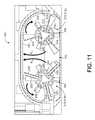
- FIG. 2is a bottom view of the robot shown in FIG. 1 .
- FIG. 3is schematic view of an exemplary robotic system.
- FIG. 4is a partial exploded view of an exemplary cleaning robot.
- FIG. 5is a bottom perspective view of the robot shown in FIG. 5 .
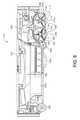
- FIG. 6is a section view of the robot shown in FIG. 4 , along line 6 - 6 .
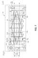
- FIG. 7is a partial bottom view of the brushes of an exemplary cleaning robot.
- FIG. 8is a partial section view of an exemplary cleaning robot, illustrating a brush bar arrangement.
- FIG. 9is a side view of an exemplary roller brush.
- FIG. 10Ais a perspective view of an exemplary roller brush having dual-rows of bristles.
- FIG. 10Bis a front view of the roller brush of FIG. 10A .
- FIG. 10Cis a side view of the roller brush of FIG. 10A .
- FIG. 11is a partial section view of an exemplary dual-brush cleaning system.
- FIG. 12Ais a bottom schematic view of an exemplary cleaning robot.
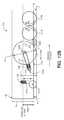
- FIG. 12Bis a side schematic view of an exemplary cleaning robot.
- FIG. 12Cis a side schematic view of an exemplary cleaning robot.
- FIG. 12Dis a schematic view of a wheel of a robot.
- An autonomous robot movably supportedcan clean a surface while traversing that surface.
- the robotcan remove debris from the surface by agitating the debris and/or lifting the debris from the surface by applying a negative pressure (e.g., partial vacuum) above the surface, and collecting the debris from the surface.
- a negative pressuree.g., partial vacuum
- a robot 100includes a body 110 supported by a drive system 120 that can maneuver the robot 100 across the floor surface 10 based on a drive command having x, y, and ⁇ components, for example.
- the robot body 110has a forward portion 112 and a rearward portion 114 .
- the drive system 120includes right and left driven wheel modules 120 a , 120 b .
- the wheel modules 120 a , 120 bare substantially opposed along a transverse axis X defined by the body 110 and include respective drive motors 122 a , 122 b driving respective wheels 124 a , 124 b .
- the drive motors 122 a , 122 bmay releasably connect to the body 110 (e.g., via fasteners or tool-less connections) with the drive motors 122 a , 122 b optionally positioned substantially over the respective wheels 124 a , 124 b .
- the wheel modules 120 a , 120 bcan be releasably attached to the chassis 110 and forced into engagement with the floor surface 10 by respective springs.
- the robot 100may include a caster wheel 126 disposed to support a rearward portion 114 of the robot body 110 .
- the robot body 110supports a power source 102 (e.g., a battery) for powering any electrical components of the robot 100 .
- the wheel modules 120 a , 120 bare movable secured (e.g., rotatably attach) to the robot body 110 and receive spring biasing (e.g., between about 5 and 25 Newtons) that biases the drive wheels 124 a , 124 b downward and away from the robot body 110 .
- spring biasinge.g., between about 5 and 25 Newtons
- the drive wheels 124 a , 124 bmay receive a downward bias of about 10 Newtons when moved to a deployed position and about 20 Newtons when moved to a retracted position into the robot body 110 .
- the spring biasingallows the drive wheels 124 a , 124 b to maintain contact and traction with the floor surface 10 while any cleaning elements of the robot 100 contact the floor surface 10 as well.
- the robot 100can move across the floor surface 10 through various combinations of movements relative to three mutually perpendicular axes defined by the body 110 : a transverse axis X, a fore-aft axis Y, and a central vertical axis Z.
- a forward drive direction along the fore-aft axis Yis designated F (sometimes referred to hereinafter as “forward”)
- an aft drive direction along the fore-aft axis Yis designated A (sometimes referred to hereinafter as “rearward”).
- the transverse axis Xextends between a right side R and a left side L of the robot 100 substantially along an axis defined by center points of the wheel modules 120 a , 120 b.
- the robot 100weighs about 10-60 N empty.
- the robot 100may have a center of gravity up to 35% of the distance from the transverse axis X (e.g., a centerline connecting the drive wheels 124 a , 124 b ) to the front of the robot 100 (i.e. the forward surface facing the direction of travel).
- the robot 100may rely on having most of its weight over the drive wheels 124 a , 124 b to ensure good traction and mobility on surfaces 10 .
- the caster 126 disposed on the rearward portion 114 of the robot body 110can support between about 0-25% of the robot's weight, and the caster 126 rides on a hard stop while the robot 100 is mobile.
- the robot 100may include one or more clearance regulators 128 a , 128 b , such as right and left non-driven wheel 128 a , 128 b rotatably supported by the robot body 110 adjacent to and forward of the drive wheels 124 a , 124 b for supporting between about 0-25% of the robot's weight and for ensuring the forward portion 112 of the robot 100 doesn't sit on the ground when accelerating.
- a forward portion 112 of the body 110carries a bumper 130 , which detects (e.g., via one or more sensors) one or more events in a drive path of the robot 100 , for example, as the wheel modules 120 a , 120 b propel the robot 100 across the floor surface 10 during a cleaning routine.
- the robot 100may respond to events (e.g., obstacles, cliffs, walls) detected by the bumper 130 by controlling the wheel modules 120 a , 120 b to maneuver the robot 100 in response to the event (e.g., away from an obstacle). While some sensors are described herein as being arranged on the bumper, these sensors can be additionally or alternatively arranged at any of various different positions on the robot 100 .
- a user interface 140 disposed on a top portion of the body 110receives one or more user commands and/or displays a status of the robot 100 .
- the user interface 140is in communication with a robot controller 150 carried by the robot 100 such that one or more commands received by the user interface 140 can initiate execution of a cleaning routine by the robot 100 .
- the robot 100may include a sensor system 500 having several different types of sensors 530 which can be used in conjunction with one another to create a perception of the robot's environment sufficient to allow the robot 100 to make intelligent decisions about actions to take in that environment.
- the sensor system 500may include obstacle detection obstacle avoidance (ODOA) sensors, communication sensors, navigation sensors, etc.
- ODOAobstacle detection obstacle avoidance
- the sensor system 500includes ranging sonar sensors 530 a (e.g., disposed on the forward body portion 112 ), proximity cliff sensors 530 b (e.g., infrared sensors), contact sensors, a laser scanner, and/or an imaging sonar.
- the sensors 530may include, but not limited to, proximity sensors, sonar, radar, LIDAR (Light Detection And Ranging, which can entail optical remote sensing that measures properties of scattered light to find range and/or other information of a distant target), LADAR (Laser Detection and Ranging), etc., infrared cliff sensors, contact sensors, a camera (e.g., volumetric point cloud imaging, three-dimensional (3D) imaging or depth map sensors, visible light camera and/or infrared camera), etc.
- LIDARLight Detection And Ranging
- LADARLaser Detection and Ranging
- infrared cliff sensorse.g., contact sensors, a camera (e.g., volumetric point cloud imaging, three-dimensional (3D) imaging or depth map sensors, visible light camera and/or infrared camera), etc.
- the robot controller 150(executing a control system) may execute behaviors that cause the robot 100 to take an action, such as maneuvering in a wall following manner, a floor scrubbing manner, or changing its direction of travel when an obstacle is detected (e.g., by a bumper sensor system 400 ).
- the robot controller 150can maneuver the robot 100 in any direction across the floor surface 10 by independently controlling the rotational speed and direction of each wheel module 120 a , 120 b .
- the robot controller 150can maneuver the robot 100 in the forward F, reverse (aft) A, right R, and left L directions.
- the robot 100can make repeated alternating right and left turns such that the robot 100 rotates back and forth around the center vertical axis Z (hereinafter referred to as a wiggle motion).
- the wiggle motioncan allow the robot 100 to operate as a scrubber during cleaning operation.
- the wiggle motioncan be used by the robot controller 150 to detect robot stasis.
- the robot controller 150can maneuver the robot 100 to rotate substantially in place such that the robot 100 can maneuver-away from an obstacle, for example.
- the robot controller 150may direct the robot 100 over a substantially random (e.g., pseudo-random) path while traversing the floor surface 10 .
- the robot controller 150can be responsive to one or more sensors 530 (e.g., bump, proximity, wall, stasis, and/or cliff sensors) disposed about the robot 100 .
- the robot controller 150can redirect the wheel modules 120 a , 120 b in response to signals received from the sensors 530 , causing the robot 100 to avoid obstacles and clutter while treating the floor surface 10 . If the robot 100 becomes stuck or entangled during use, the robot controller 150 may direct the wheel modules 120 a , 120 b through a series of escape behaviors so that the robot 100 can escape and resume normal cleaning operations.
- the robot 100includes a navigation system 600 configured to maneuver the robot 100 in a pseudo-random pattern across the floor surface 10 such that the robot 100 is likely to return to the portion of the floor surface 10 upon which cleaning fluid has remained.
- the navigation system 600may be a behavior based system stored and/or executed on the robot controller 150 .
- the navigation system 600may communicate with the sensor system 500 to determine and issue drive commands to the drive system 120 .
- the robot 100includes a cleaning system 160 having a cleaning subsystem 300 , such as a dry cleaning system 300 .
- the dry cleaning system 300includes at least one roller brush 310 (e.g., with bristles and/or beater flaps) extending parallel to the transverse axis X and rotatably supported by the robot body 110 to contact the floor surface 10 .
- the brush 310includes first and second ends 311 , 313 , each end is releasably connected to the robot body 110 .
- the cleaning system 160includes a cleaning head 180 for receiving the roller brush 310 .
- the roller brush 310may be releasably connected to the cleaning head 180 .
- the cleaning head 180is positioned in the forward portion 112 of the robot body 110 .
- the cleaning head 180defines a recess 184 having a rectangular shape for receiving the roller brush(es) 310 .
- the recess 184allows the brush(es) 310 to be in contact with a floor surface 10 for cleaning.
- the cleaning head 180also defines a plenum 182 arranged over the roller brush 310 .
- a conduit or ducting 208provides pneumatic communication between the plenum 182 and the collection volume 202 b.
- the roller brush 310 a , 310 bmay be driven by a corresponding brush motor 312 a , 312 b or by one of the wheel drive motors 122 a , 122 b .
- the driven roller brush 310agitates debris on the floor surface 10 , moving the debris into a suction path for evacuation to the collection volume 202 b . Additionally or alternatively, the driven roller brush 310 may move the agitated debris off the floor surface 10 and into a collection bin (not shown) adjacent the roller brush 310 or into the ducting 208 .
- the roller brush 310may rotate so that the resultant force on the floor 10 pushes the robot 100 forward.
- the robot body 110may include a removable cover 104 allowing access to the collection bin, and may include a handle 106 for releasably accessing the collection volume 202 b.
- the robot body 110includes a side brush 140 disposed on the bottom forward portion 112 of the robot body 110 .
- the side brush 140agitates debris on the floor surface 10 , moving the debris into the suction path of a vacuum module 162 .
- the side brush 140extends beyond the robot body 110 allowing the side brush 140 to agitate debris in hard to reach areas such as corners and around furniture.
- the cleaning system 160includes first and second roller brushes 310 a , 310 b .
- the brushes 310 a , 310 brotate simultaneously to remove dirt from a surface 10 .
- Each brush 310 a , 310 bincludes a brush core 314 defining a longitudinal axis of rotation X A , X B .
- the brushes 310 a , 310 brotate simultaneously about their longitudinal axes of rotation X A , X B to remove dirt from a surface 10 .
- the brushes 310 a , 310 bmay rotate in the same or opposite directions about their respective longitudinal axis X A , X B .
- the robot 100includes first and second brush motors 312 a , 312 b .
- the first brush motor 312 ais coupled to the first roller brush 310 a and drives the first roller brush 310 a in a first direction.
- the second brush motor 312 bis coupled to the second roller brush 310 b and drives the second roller brush 310 b in a second direction opposite the first direction.
- the first direction of rotationmay be a forward rolling direction with respect to the forward drive direction F.
- the first roller brush 310 aincludes at least two longitudinal rows 315 of bristles 318 circumferentially spaced about the brush core 314 .
- Each bristle 318extends away from a first end 318 a attached to the brush core 314 to a second end 318 b unattached from the brush core 314 .
- the bristles 318may all have substantially the same length L B .
- the second roller brush 310 bincludes at least two longitudinal dual-rows 325 of bristles 320 , 330 circumferentially spaced about the brush core 314 .
- Each dual-row 325has a first row 325 a of bristles 320 having a first bristle length LB1 and a second row 325 b of bristles 330 adjacent and parallel the first bristle row 325 a and having a second bristle length LB2 different from the first bristle length LB1 (e.g., the second bristle length LB2 is greater than the first bristle length LB1).
- the first and second bristle rows 325 a , 325 bare separated circumferentially along the brush core 314 by narrow gap.
- a chord distance DCis less than about 1 ⁇ 4 the first bristle length LB1.
- each bristle 320 , 330may extend away from a first end 320 a , 330 a attached to the brush core 314 to a second end 320 b , 330 b unattached from the brush core 314 .
- the first bristle length LB1is less than 90% of the second bristle length LB2.
- first bristle row 325 a of each dual-row 325 of bristles 320 , 330may be forward of the second row 325 b of bristles 330 in the direction of rotation RB of the second roller brush 310 b.
- the first row 325 a of bristles 320is formed of a first bristle composition and the second row 325 b of bristles 330 is formed of a second bristle composition, and the first bristle composition is stiffer than the second bristle composition.
- the first bristle length L B1may be no more than 90% of second bristle length L B2
- the first row 325 a and second row 325 bmay be separated by a narrow gap of no more than 10% of second bristle length L B2 (i.e. no more 10% of the length of the longer bristles 330 ).
- the second roller brush 310 bhas three or more dual rows of bristles 320 , 330 equidistantly separated along the circumference of the brush core by 60 to 120 degrees. Having more than five dual rows 325 is costly and also results in excessive power draw on the motor driving the second roller brush 310 b . Having fewer than three dual rows 325 results in poor cleaning performance because the bristles 330 do not contact the surface being cleaned with sufficient frequency.
- the first roller brush 310 amay include three or more rows of single height bristles 318 . Additionally or alternatively, the first roller brush 310 a may include one or more dual-rows 325 of bristles 320 , 330 identical to those shown and described herein with reference to the second roller brush 310 of FIG. 10C .
- a bristle offset O in a brush 310is how far forward or behind the center axis X A , X B of the brush 310 the bristles 318 , 320 , 330 are mounted with respect to the intended direction R A of brush 310 rotation.
- Bristles 318 , 320 , 330 mounted forward of the center axis X A , X Bwill naturally be swept-back when contacting the floor 10 , while bristles 318 , 320 , 330 mounted behind the center axis X A , X B will drive the bristles 318 , 320 , 330 further into the floor 10 (resulting in higher power consumption and the potential for “brush bounce”).
- Bristles 318 , 320 , 330 mounted in front of the center axis X A , X B of the brush 310yield longer bristles 318 , 320 , 330 for the same effective diameter, creating a brush 310 that is relatively less stiff.
- a current draw or power consumption while traversing and cleaning a carpeted floor surface 10can be significantly reduced compared to a rear offset bristle configuration.
- the bristles 318 , 320 , 330have an offset of between 0 and 3 mm (e.g., 1 mm) behind the center axis X A , X B of the brush 310 .
- a spacing distance D Smeasured along the Y-axis, between the longitudinal axes of rotation X A , X B is greater than or equal to a diameter ⁇ A , ⁇ B of the brushes 310 a , 310 b .
- the brushes 310 a , 310 bare spaced apart such that distal second ends 318 b , 320 b of their respective bristles 318 , 320 , 330 are distanced by a gap of about 1-10 mm.
- one or both brushes 310 a , 310 binclude vanes 340 arranged between and substantially parallel to the rows 315 of bristles 318 or dual-rows 325 of bristles 320 , 330 .
- Each vane 340includes an elastomeric material that extends from a first end 340 a attached to the brush core 314 to a second end 340 b unattached from the brush core 314 .
- the vanes 340prevent hair from wrapping about the brush core 314 . Additionally, the vanes 340 keep the hair towards the outer portion of the brush core 314 for easier removal and cleaning.
- the vanes 340may extend in a straight line or define a chevron shape on the brush core 314 .
- the vanes 340may be shorter than the bristles 318 , 320 , 330 .
- the vanes 340facilitate the removal of hair wrapped around the brush core 314 because the vanes 340 prevent the hair from deeply wrapping tightly around the brush core 314 .
- the vanes 340increase the airflow past the brushes 310 a , 310 b , which in turn increases the deposition of hair and other debris into the dust bin 202 b . Since the hair is not deeply wrapped around the core 314 of the brush 310 , the vacuum may still pull the hair off the brush 310 .
- each brush core 314defines a longitudinally extending T-shaped channel 360 for releasably receiving a brush element 370 .
- the brush element 370includes an anchor 372 defining a T-shape and complimentary sized for slidable receipt into the T-shaped channel 360 , and at least one longitudinal row of bristles 318 , 320 , 330 or a vane 340 attached to the anchor 372 .
- the T-shaped anchor 372allows a user to slide the brush element 370 on and off the brush core 314 for servicing, while also preventing escapement of the bristles during operation of the brush 310 .
- the channel 360defines other shapes for releasably receiving a brush element 370 having a complimentary shape sized for slidably being received by the channel 360 .
- the channels 360may be equidistantly circumferentially spaced about the brush core 314 .
- the brushes 3100 a , 310 bmay scrape the debris off the plenum 182 , thus minimizing debris accumulation.
- the dual-row 325 of bristles 320 , 330has a first row 325 a a bristle diameter ⁇ A of 0.003-0.010 inches (e.g., 0.009 inches) adjacent and parallel to a second bristle row 325 b having a bristle diameter ⁇ B of between 0.001-0.007 inches (e.g., 0.005 inches).
- the first bristle row 325 a(the lesser diameter bristle row) is relatively stiffer than the second bristle row 325 b (the larger diameter bristle row) to impede filament winding about the brush core 314 .
- the bristles 320 , 330 of at least one of the bristle rows 325 a , 325 bmay be long enough to interfere with the plenum 182 keeping the inside of the plenum 182 clean and allowing for a longer reach into transitions and grout lines on the floor surface 10 .
- the hairmay not be directly transferred from the surface 10 to the collection bin 202 b , but rather may require some time for the hair to migrate from the brush 310 and into the plenum 182 and then to the collection bin 202 b .
- Denser and/or stiffer bristles 320 , 330may entrap the hair on the brush 310 , causing relatively less deposition of the hair in the collection bin 202 b .
- a combination of soft and stiff bristles 320 , 330where the soft bristles 330 are longer than the stiff bristles 320 , allows the hair to be trapped in the longer soft bristles 330 and therefore migrate to the collection bin 202 b faster.
- the combination of denser and/or stiffer bristles 320 , 330enables retrieval of debris, particularly hair, from myriad surface types.
- the first s row of bristles 325 aare effective at picking up debris from hard flooring and hard carpet.
- the soft bristlesare better at being compliant and releasing collected hair into the plenum.
- the cleaning head 180may releasably connect to the robot body 110 and/or the cleaning system 160 to allow removal by the user to clean any accumulated dirt or debris from within the cleaning head 180 .
- a usercan remove the cleaning head 180 (e.g., by releasing tool-less connectors or fasteners) for emptying the collection volume 202 b by grabbing and pulling a handle 106 located on the robot body 110 .
- the cleaning headincludes a wire bail 190 to prevent larger objects (e.g., wires, cords, and clothing) from wrapping around the brushes.
- the wire bailsmay be located vertically or horizontally, or may include a combination of both vertical and horizontal arrangement.
- the robot 100includes at least one brush bar 200 a , 200 b arranged parallel to and engaging the bristles 318 , 320 , 330 of one of the roller brushes 310 a , 310 b .
- the brush bar(s) 200 a , 200 binterfere with the rotation of the engaged roller brush 310 a , 310 b to strip fibers or filaments from the engaged bristles 318 , 320 , 330 .
- the brushes 310 a , 310 brotate to clean a floor surface 10 , the bristles 318 , 320 , 330 make contact with the brush bar 200 a , 200 b .
- the brush bar(s) 200 a , 200 bagitate debris (e.g., hair) on the ends of the brushes 310 a , 310 b and swipes them into the vacuum airflow for deposition into the collection volume 202 b .
- the roller brush 310allows the robot 100 to increase its collection of debris specifically hair in the collection bin 202 b , and reduce hair entangling on the brushes 310 a , 310 b .
- a brush bar 200 ainterferes minimally with only the second bristle row 325 b and does not interfere with the stiffer bristles of the first bristle row 325 a .
- the brush bar 200 a , 200 bmay interfere with the second end 330 b of the softer bristles 330 of the second bristle row 325 b and engage them by an engagement distance E, measured radially with respect to the corresponding brush core 314 , of between 0.010-0.060 inches of the length L B2 of the softer bristles 330 .
- the robot 100includes a caster wheel assembly 126 located in the rearward portion 114 of the robot 100 and may be disposed about the fore-aft axis Y.
- the caster wheel assembly 126includes a caster wheel 127 a supported for vertical movement and a suspension spring 127 b biasing the caster wheel 127 a toward the floor surface 10 .
- the suspension spring 127 bhas a spring constant sufficient to elevate a rearward portion 114 of the robot body 110 above the floor surface 10 to maintain engagement of the at least one cleaning element (e.g. roller brushes 310 a , 310 b ) with the floor surface 10 .
- the suspension spring 127 bsupports the rear end 116 of the robot body 110 at a height H above the floor surface 10 that causes engagement of at least 5% of a bristle length L B (e.g., the first and/or second bristle length L B1 , L B2 ) of the roller brush bristles 318 , 320 , 330 with the floor surface 10 .
- the center of gravity CG of the robot 100may be located forward of the drive axis (0-35%) to help maintain the forward portion 112 of the body 110 downward, causing engagement of the roller brushes 310 a , 310 b with the floor 10 .
- that center of gravity placementallows the robot body 110 to pivot forwards about the drive wheels 124 a , 124 b.
- the caster wheel assembly 126is a vertically spring-loaded swivel caster 126 biased to maintain contact with a floor surface 10 .
- the vertically spring-loaded swivel caster wheel assembly 126may be used to detect if the robot 100 is no longer in contact with a floor surface 10 (e.g., when the robot 100 backs up off a stair allowing the vertically spring-loaded swivel caster 126 to drop). Additionally, the caster wheel assembly 126 keeps the rear portion 114 of the robot body 110 off the floor surface 10 and prevents the robot 100 from scraping the floor surface 10 as it traverses the surface 10 or as the robot 100 climbs obstacles. Additionally, the vertically spring-loaded swivel caster assembly 126 allows for a tolerance in the location of the center of gravity CG to maintain contact between the roller brushes 310 a , 310 b and the floor 10 .
- the robot 100includes at least one clearance regulator 128 disposed on the robot body 110 in a forward portion 112 , forward of the drive wheels 124 a , 124 b .
- the clearance regulator 128is a roller or wheel rotatably supported by the robot body 110 .
- the clearance regulator 128may be right and left rollers 128 a , 128 b disposed forward of the drive wheels 124 a , 124 b and rearward of the roller brushes 310 .
- the clearance regulators/rollers 128 a , 128 bmay maintain a clearance height C (e.g., at least 5 mm) between a bottom surface 118 of the robot body 110 and the floor surface 10 .
- each drive wheel 124 a , 124 bis rotatably supported by a drive wheel suspension arm 123 having a first end 123 a pivotally coupled to the robot body 110 and a second end 123 b rotatably supporting the drive wheel 124 a , 124 b , and a drive wheel suspension spring 125 biasing the drive wheel 124 a , 124 b toward the floor surface 10 .
- the drive wheel suspension arm 123is a bracket ( FIG. 12C ) having a pivot point 127 a , a wheel pivot 127 b , and spring anchor 127 c spaced from the pivot point 127 a and the wheel pivot 127 b .
- a spring 125 biasing the spring anchor 127 bcauses the suspension arm 123 to rotate about the pivot point 127 a (i.e., a fulcrum) to move the drive wheel 124 a , 124 b toward the floor surface 10 .
- the suspension arm 123is an L-shaped bracket having first and second legs 123 L 1 , 123 L 2 .
- the pivot point 123 a , 127 a of the bracket 123may be positioned in a lower 25% of a height H R of the robot 100 and is at least below half the height H R of the robot body 110 , with respect to the floor surface 10 .
- a hypotenuse of the L-shaped bracket 123may have a length L 1 equal to between 70% and 150% of the height H R of the robot body 110 .
- Each drive wheel 124 a , 124 bmay have a diameter ⁇ D equal to between 75% and 120% of the height H R of the robot body 110 .
- ⁇is the angle between the drive wheel suspension arm 123 with respect to a horizontal top portion of the robot body 110 .
- Ris the radius of the wheel 124 a , 124 b
- L Ais the length of the wheel arm 123 .
- the tractionequals to zero only when the pivot point is on the floor surface 10 . Therefore, to improve performance in the weak direction, the pivot point should be as close to zero and therefore as close to the floor surface 10 .
- the lower the pivot pointthe better the performance of the wheels 124 a , 124 b .
- the following two equationsare considered for improving wheel performance:
- ⁇is the angle between the drive wheel suspension arm 123 with respect to a horizontal top portion of the robot body 110 .
- Ris the radius of the wheel 124 a , 124 b
- L Ais the length of the wheel arm 123 .
- F sis the normal spring force and F n is the maximum allowable weight limit.
- F S2.5 lbf (constant)
- the wheel radius R41 mm
- mu0.8 (coefficient of friction).
- the maximum allowable Fn (Weight Limited)2.5 lbf per wheel.
- the robot 100has forward body portion 112 having a flat forward face (e.g., a flat linear bumper 130 ), and a rearward body portion 114 defining a semi-circular shape.
- a flat forward facee.g., a flat linear bumper 130
- a rearward body portion 114defining a semi-circular shape.
- the robot 100may need to drive backwards to escape the corner and/or wall.
- a higher tractionis needed when the robot 100 is moving backwards to improve the escape capabilities when the robot 100 is stuck.
Landscapes
- Engineering & Computer Science (AREA)
- Mechanical Engineering (AREA)
- Nozzles For Electric Vacuum Cleaners (AREA)
- Electric Vacuum Cleaner (AREA)
- Electric Suction Cleaners (AREA)
Abstract
Description
Claims (23)
Priority Applications (8)
| Application Number | Priority Date | Filing Date | Title |
|---|---|---|---|
| US13/835,501US9326654B2 (en) | 2013-03-15 | 2013-03-15 | Roller brush for surface cleaning robots |
| PCT/US2014/025865WO2014151501A1 (en) | 2013-03-15 | 2014-03-13 | Surface cleaning robot |
| EP14769162.0AEP2833775B1 (en) | 2013-03-15 | 2014-03-13 | Surface cleaning robot |
| PCT/US2014/025665WO2014151408A1 (en) | 2013-03-15 | 2014-03-13 | Roller brush for surface cleaning robots |
| CN201490000266.XUCN204950812U (en) | 2013-03-15 | 2014-03-13 | A cylinder brush for surface cleaning robot |
| JP2015511820AJP6231084B2 (en) | 2013-03-15 | 2014-03-13 | Surface cleaning robot |
| DE112014000174.0TDE112014000174T5 (en) | 2013-03-15 | 2014-03-13 | Roller brush for surface cleaning robots |
| US15/088,802US10292560B2 (en) | 2013-03-15 | 2016-04-01 | Roller brush for surface cleaning robots |
Applications Claiming Priority (1)
| Application Number | Priority Date | Filing Date | Title |
|---|---|---|---|
| US13/835,501US9326654B2 (en) | 2013-03-15 | 2013-03-15 | Roller brush for surface cleaning robots |
Related Child Applications (1)
| Application Number | Title | Priority Date | Filing Date |
|---|---|---|---|
| US15/088,802ContinuationUS10292560B2 (en) | 2013-03-15 | 2016-04-01 | Roller brush for surface cleaning robots |
Publications (2)
| Publication Number | Publication Date |
|---|---|
| US20140259475A1 US20140259475A1 (en) | 2014-09-18 |
| US9326654B2true US9326654B2 (en) | 2016-05-03 |
Family
ID=51520521
Family Applications (2)
| Application Number | Title | Priority Date | Filing Date |
|---|---|---|---|
| US13/835,501Active2034-08-29US9326654B2 (en) | 2013-03-15 | 2013-03-15 | Roller brush for surface cleaning robots |
| US15/088,802Active2034-07-17US10292560B2 (en) | 2013-03-15 | 2016-04-01 | Roller brush for surface cleaning robots |
Family Applications After (1)
| Application Number | Title | Priority Date | Filing Date |
|---|---|---|---|
| US15/088,802Active2034-07-17US10292560B2 (en) | 2013-03-15 | 2016-04-01 | Roller brush for surface cleaning robots |
Country Status (6)
| Country | Link |
|---|---|
| US (2) | US9326654B2 (en) |
| EP (1) | EP2833775B1 (en) |
| JP (1) | JP6231084B2 (en) |
| CN (1) | CN204950812U (en) |
| DE (1) | DE112014000174T5 (en) |
| WO (2) | WO2014151501A1 (en) |
Cited By (23)
| Publication number | Priority date | Publication date | Assignee | Title |
|---|---|---|---|---|
| US20150320278A1 (en)* | 2014-05-07 | 2015-11-12 | Lg Electronics Inc. | Vacuum cleaner |
| US20150342426A1 (en)* | 2013-05-28 | 2015-12-03 | Silvia Panico | Hair remover |
| US20160058256A1 (en)* | 2014-09-02 | 2016-03-03 | Lotes Co., Ltd | Intelligent cleaning robot |
| US20190029409A1 (en)* | 2017-07-25 | 2019-01-31 | Irobot Corporation | Cleaning roller for cleaning robots |
| USD841268S1 (en)* | 2017-03-18 | 2019-02-19 | AI Incorporated | Rotating brush |
| US10239370B2 (en)* | 2017-08-02 | 2019-03-26 | AI Incorporated | Wheel suspension system |
| US10271699B2 (en) | 2016-04-14 | 2019-04-30 | Beijing Xiaomi Mobile Software Co., Ltd. | Autonomous cleaning device and wind path structure of same |
| USD850039S1 (en)* | 2017-08-31 | 2019-05-28 | Beijing Xiomi Mobile Software Co., Ltd. | Cleaning element for a robotic vacuum |
| US10470636B2 (en) | 2017-01-17 | 2019-11-12 | Irobot Corporation | Mobile cleaning robot cleaning head |
| US10512384B2 (en) | 2016-12-15 | 2019-12-24 | Irobot Corporation | Cleaning roller for cleaning robots |
| US10722022B2 (en) | 2018-03-29 | 2020-07-28 | Omachron Intellectual Property Inc | Rotatable brush for surface cleaning apparatus |
| US10722087B2 (en) | 2018-03-29 | 2020-07-28 | Omachron Intellectual Property Inc. | Rotatable brush for surface cleaning apparatus |
| US10765279B2 (en) | 2018-03-29 | 2020-09-08 | Omachron Intellectual Property Inc. | Rotatable brush for surface cleaning apparatus |
| US10888205B2 (en) | 2018-03-29 | 2021-01-12 | Omachron Intellectual Property Inc. | Rotatable brush for surface cleaning apparatus |
| US10898042B2 (en) | 2017-08-16 | 2021-01-26 | Sharkninja Operating Llc | Robotic vacuum |
| US10905297B2 (en) | 2018-01-05 | 2021-02-02 | Irobot Corporation | Cleaning head including cleaning rollers for cleaning robots |
| US10925447B2 (en) | 2017-03-10 | 2021-02-23 | Sharkninja Operating Llc | Agitator with debrider and hair removal |
| US10932631B2 (en) | 2018-03-29 | 2021-03-02 | Omachron Intellectual Property Inc. | Rotatable brush for surface cleaning apparatus |
| US11109727B2 (en) | 2019-02-28 | 2021-09-07 | Irobot Corporation | Cleaning rollers for cleaning robots |
| JPWO2020246026A1 (en)* | 2019-06-07 | 2021-10-14 | 三菱電機株式会社 | Vacuum cleaner head and vacuum cleaner |
| US20210330151A1 (en)* | 2020-04-24 | 2021-10-28 | Techtronic Cordless Gp | Floor cleaner including an agitator |
| US11202542B2 (en) | 2017-05-25 | 2021-12-21 | Sharkninja Operating Llc | Robotic cleaner with dual cleaning rollers |
| US11291345B2 (en) | 2018-08-27 | 2022-04-05 | Techtronic Floor Care Technology Limited | Floor cleaner |
Families Citing this family (98)
| Publication number | Priority date | Publication date | Assignee | Title |
|---|---|---|---|---|
| WO2014169943A1 (en) | 2013-04-15 | 2014-10-23 | Aktiebolaget Electrolux | Robotic vacuum cleaner |
| KR102083188B1 (en)* | 2013-07-29 | 2020-03-02 | 삼성전자주식회사 | Cleaning robot and method for controlling the same |
| USD744183S1 (en)* | 2013-09-26 | 2015-11-24 | Samsung Electronics Co., Ltd. | Robot cleaner |
| USD745233S1 (en)* | 2013-09-26 | 2015-12-08 | Samsung Electronics Co., Ltd. | Robot cleaner |
| USD744178S1 (en)* | 2013-09-26 | 2015-11-24 | Samsung Electronics Co., Ltd. | Cleaner |
| USD744181S1 (en)* | 2013-09-26 | 2015-11-24 | Samsung Electronics Co., Ltd. | Robot cleaner |
| USD746005S1 (en)* | 2013-09-26 | 2015-12-22 | Samsung Electronics Co., Ltd. | Robot cleaner |
| USD744708S1 (en)* | 2013-09-26 | 2015-12-01 | Samsung Electronics Co., Ltd. | Cleaner brush |
| USD744709S1 (en)* | 2013-09-26 | 2015-12-01 | Samsung Electronics Co., Ltd. | Robot cleaner body |
| USD745757S1 (en)* | 2013-09-26 | 2015-12-15 | Samsung Electronics Co., Ltd. | Robot cleaner |
| USD737008S1 (en)* | 2013-09-26 | 2015-08-18 | Samsung Electronics Co., Ltd. | Robot cleaner |
| USD761507S1 (en)* | 2013-10-10 | 2016-07-12 | Samsung Electronics Co., Ltd. | Cleaner |
| USD737006S1 (en)* | 2013-10-10 | 2015-08-18 | Samsung Electronics Co., Ltd. | Cleaner |
| US10433697B2 (en) | 2013-12-19 | 2019-10-08 | Aktiebolaget Electrolux | Adaptive speed control of rotating side brush |
| US10617271B2 (en) | 2013-12-19 | 2020-04-14 | Aktiebolaget Electrolux | Robotic cleaning device and method for landmark recognition |
| CN206995197U (en)* | 2014-03-19 | 2018-02-13 | 尚科宁家运营有限公司 | Floor treating apparatus |
| WO2016004578A1 (en)* | 2014-07-08 | 2016-01-14 | 浙江工业大学 | Mobile printer and printing method thereof |
| CN106415423B (en) | 2014-07-10 | 2021-01-01 | 伊莱克斯公司 | Method for detecting a measurement error of a robotic cleaning device |
| USD778514S1 (en)* | 2014-07-17 | 2017-02-07 | Samsung Electronics Co., Ltd | Robot cleaner |
| EP3190938A1 (en) | 2014-09-08 | 2017-07-19 | Aktiebolaget Electrolux | Robotic vacuum cleaner |
| US10499778B2 (en) | 2014-09-08 | 2019-12-10 | Aktiebolaget Electrolux | Robotic vacuum cleaner |
| US11992172B2 (en) | 2018-10-19 | 2024-05-28 | Sharkninja Operating Llc | Agitator for a surface treatment apparatus and a surface treatment apparatus having the same |
| EP3230814B1 (en) | 2014-12-10 | 2021-02-17 | Aktiebolaget Electrolux | Using laser sensor for floor type detection |
| US10568483B2 (en)* | 2014-12-12 | 2020-02-25 | Irobot Corporation | Cleaning system for autonomous robot |
| CN107072454A (en) | 2014-12-12 | 2017-08-18 | 伊莱克斯公司 | Side brushes and robot vacuums |
| CN107003669B (en) | 2014-12-16 | 2023-01-31 | 伊莱克斯公司 | Experience-Based Roadmap for Robotic Cleaning Equipment |
| EP3234713B1 (en) | 2014-12-16 | 2022-06-15 | Aktiebolaget Electrolux | Cleaning method for a robotic cleaning device |
| WO2016100878A1 (en)* | 2014-12-19 | 2016-06-23 | Techtronic Industries Co. Ltd. | Autonomous vacuum |
| US9630319B2 (en) | 2015-03-18 | 2017-04-25 | Irobot Corporation | Localization and mapping using physical features |
| KR101644887B1 (en)* | 2015-03-24 | 2016-08-02 | 엘지전자 주식회사 | Agitator and Robot cleaner inculding the same |
| US9866035B2 (en) | 2015-03-27 | 2018-01-09 | Irobot Corporation | Rotatable coupling |
| KR102320199B1 (en)* | 2015-04-13 | 2021-11-02 | 삼성전자주식회사 | Driving unit and robot cleaner having the same |
| US11099554B2 (en) | 2015-04-17 | 2021-08-24 | Aktiebolaget Electrolux | Robotic cleaning device and a method of controlling the robotic cleaning device |
| JP6719864B2 (en)* | 2015-04-21 | 2020-07-08 | シャープ株式会社 | Vacuum cleaner |
| TWI580387B (en)* | 2015-05-27 | 2017-05-01 | 趙志謀 | Robot |
| EP3344104B1 (en) | 2015-09-03 | 2020-12-30 | Aktiebolaget Electrolux | System of robotic cleaning devices |
| US10702108B2 (en) | 2015-09-28 | 2020-07-07 | Sharkninja Operating Llc | Surface cleaning head for vacuum cleaner |
| JP6556016B2 (en)* | 2015-10-16 | 2019-08-07 | 日立グローバルライフソリューションズ株式会社 | Autonomous traveling vacuum cleaner |
| WO2017070492A1 (en) | 2015-10-21 | 2017-04-27 | Sharkninja Operating Llc | Surface cleaning head with dual rotating agitators |
| US11647881B2 (en) | 2015-10-21 | 2023-05-16 | Sharkninja Operating Llc | Cleaning apparatus with combing unit for removing debris from cleaning roller |
| RU2688975C1 (en)* | 2015-10-26 | 2019-05-23 | Конинклейке Филипс Н.В. | Vacuum cleaner nozzle |
| CN105686759A (en)* | 2015-12-09 | 2016-06-22 | 柳州市京阳节能科技研发有限公司 | An intelligent control efficient energy-saving cleaning device |
| EP3393323B1 (en)* | 2015-12-22 | 2021-07-21 | Run The Race Pty Ltd | Improved vacuum head attachment and vacuum cleaner |
| US11122953B2 (en) | 2016-05-11 | 2021-09-21 | Aktiebolaget Electrolux | Robotic cleaning device |
| CN106073636A (en)* | 2016-08-15 | 2016-11-09 | 天佑电器(苏州)有限公司 | Floor brush assembly |
| CN106073637A (en)* | 2016-08-15 | 2016-11-09 | 天佑电器(苏州)有限公司 | Floor brush assembly |
| CN106180109B (en)* | 2016-08-22 | 2018-07-17 | 欧贝黎新能源科技股份有限公司 | A kind of photovoltaic plant Special cleaning machine people |
| US10732127B2 (en)* | 2016-10-26 | 2020-08-04 | Pixart Imaging Inc. | Dirtiness level determining system and surface cleaning machine |
| CN207492728U (en)* | 2016-12-15 | 2018-06-15 | 美国iRobot公司 | It may be mounted to the clearer of clean robot |
| CN107049152B (en)* | 2017-03-31 | 2022-07-29 | 苏州爱普电器有限公司 | Stirring brush for floor cleaning device |
| US11284702B2 (en) | 2017-05-15 | 2022-03-29 | Sharkninja Operating Llc | Side brush with bristles at different lengths and/or angles for use in a robot cleaner and side brush deflectors |
| EP3629869B1 (en) | 2017-06-02 | 2023-08-16 | Aktiebolaget Electrolux | Method of detecting a difference in level of a surface in front of a robotic cleaning device |
| US20200089249A1 (en)* | 2017-06-07 | 2020-03-19 | Chiba Institute Of Technology | Self-propelled vacuum |
| US10575701B2 (en)* | 2017-09-15 | 2020-03-03 | Omachron Intellectual Property Inc. | Surface cleaning apparatus |
| EP3687357B1 (en) | 2017-09-26 | 2024-07-10 | Aktiebolaget Electrolux | Controlling movement of a robotic cleaning device |
| KR20190054517A (en)* | 2017-11-13 | 2019-05-22 | 삼성전자주식회사 | Cleaner |
| WO2019097736A1 (en)* | 2017-11-16 | 2019-05-23 | シャープ株式会社 | Wheel support structure for self-propelled electronic device |
| WO2019174762A1 (en)* | 2018-03-16 | 2019-09-19 | Husqvarna Ab | Material collection equipment |
| CN108294696A (en)* | 2018-03-22 | 2018-07-20 | 深圳市银星智能科技股份有限公司 | Clean robot |
| JP7079031B2 (en)* | 2018-03-28 | 2022-06-01 | 山西嘉世達机器人技術有限公司 | Wiping robot |
| US10856710B2 (en) | 2018-04-09 | 2020-12-08 | Jiangsu Midea Cleaning Appliances Co., Ltd. | Brushroll and robot vacuum cleaner |
| CN208659190U (en)* | 2018-04-09 | 2019-03-29 | 江苏美的清洁电器股份有限公司 | Round brush and sweeping robot |
| CN108577684A (en)* | 2018-05-15 | 2018-09-28 | 江苏美的清洁电器股份有限公司 | Dust collecting installation |
| CN108972622A (en)* | 2018-07-26 | 2018-12-11 | 芜湖市越泽机器人科技有限公司 | A kind of anticollision robot chassis |
| CN108888177B (en)* | 2018-08-16 | 2024-07-02 | 天佑电器(苏州)有限公司 | Rolling brush assembly and cleaning device with same |
| CN109340335B (en)* | 2018-09-11 | 2021-08-24 | 安克创新科技股份有限公司 | Intelligent self-moving equipment and speed reduction device thereof |
| JP2020062158A (en)* | 2018-10-16 | 2020-04-23 | シャープ株式会社 | Auxiliary wheel support structure of self-traveling electronic apparatus |
| CN116158688A (en) | 2018-10-19 | 2023-05-26 | 尚科宁家运营有限公司 | Vacuum cleaner and agitator for a vacuum cleaner |
| CH715633A2 (en)* | 2018-12-12 | 2020-06-15 | Kemaro Ag | Device and method for automatically performing an activity, in particular for cleaning dirty surfaces. |
| CN109602331B (en)* | 2019-01-23 | 2024-05-03 | 东莞优乐家智能家电有限公司 | Double-roller cleaning equipment with automatic hair removing function |
| CN111820818A (en)* | 2019-04-16 | 2020-10-27 | 添可智能科技有限公司 | Cleaning equipment and its brushes |
| CN110076116B (en)* | 2019-05-10 | 2022-04-08 | 河北科技师范学院 | Glass Fragment Collection System for Solar Module Lamination Line |
| KR102723223B1 (en)* | 2019-08-29 | 2024-10-30 | 삼성전자주식회사 | Caster device, robot having the same, and robot driving method |
| KR102844745B1 (en)* | 2019-09-27 | 2025-08-11 | 엘지전자 주식회사 | Robotic Cleaner |
| CN112568812A (en)* | 2019-09-29 | 2021-03-30 | 北京石头世纪科技股份有限公司 | Driving wheel module and self-moving robot |
| CN112741544B (en)* | 2019-10-30 | 2025-07-01 | 浙江绍兴苏泊尔生活电器有限公司 | Vacuum cleaner floor brush and vacuum cleaner |
| GB2590441B (en)* | 2019-12-18 | 2022-02-23 | Dyson Technology Ltd | Cleaner head for a vacuum cleaning appliance |
| WO2021163078A1 (en) | 2020-02-10 | 2021-08-19 | Matician, Inc. | Self-actuated autonomous vacuum for cleaning various mess types |
| JP6937859B1 (en)* | 2020-03-26 | 2021-09-22 | 深▲せん▼市極摩科技有限公司Shenzhen Geemo Technology Co.,Ltd. | Wet and dry separation type floor cleaning brush |
| WO2021207139A1 (en)* | 2020-04-06 | 2021-10-14 | Sharkninja Operating Llc | Allergen reduction device |
| CN111317400B (en)* | 2020-04-22 | 2022-03-01 | 追觅创新科技(苏州)有限公司 | A floor brush and a sweeper including the floor brush |
| CN112137505B (en)* | 2020-08-31 | 2022-08-12 | 追觅创新科技(苏州)有限公司 | A method and device for automatic cleaning equipment to identify ground features |
| CN112587030B (en)* | 2020-12-24 | 2025-08-08 | 珠海格力电器股份有限公司 | Roller brush assembly, roller brush mechanism and sweeping robot |
| CN113069051A (en)* | 2021-04-14 | 2021-07-06 | 深圳市杉川机器人有限公司 | Floor cleaning machine |
| GB2606154B (en)* | 2021-04-26 | 2023-12-27 | Dyson Technology Ltd | Brushbar for a vacuum cleaner |
| CN113273928B (en)* | 2021-05-07 | 2022-06-03 | 贵州工程应用技术学院 | Industrial cleaning robot |
| US11684227B2 (en)* | 2021-06-02 | 2023-06-27 | Bissell Inc. | Surface cleaning apparatus having a brushroll |
| CN113498999A (en)* | 2021-07-26 | 2021-10-15 | 苏州威摩尔智能科技有限公司 | Double-rolling brush type cleaning device |
| US12137856B2 (en) | 2021-11-22 | 2024-11-12 | Irobot Corporation | Trajectory-based localization and mapping |
| EP4241642A1 (en)* | 2022-03-07 | 2023-09-13 | Versuni Holding B.V. | Controller for controlling a floor cleaning device, floor cleaning device and nozzle thereof |
| CN116919257A (en)* | 2022-04-08 | 2023-10-24 | 北京石头世纪科技股份有限公司 | cleaning robot |
| US20230391217A1 (en)* | 2022-06-02 | 2023-12-07 | Ford Global Technologies, Llc | Self-locating charging systems for charging electrified vehicles |
| US20250261812A1 (en)* | 2022-09-23 | 2025-08-21 | Techtronic Floor Care Technology Limited | Cord saver rib |
| CN116998954A (en)* | 2022-12-30 | 2023-11-07 | 北京石头世纪科技股份有限公司 | Automatic cleaning equipment |
| CN116898321A (en)* | 2023-07-24 | 2023-10-20 | 苏州市春菊电器有限公司 | Fluff brush structure of dust collector floor brush |
| CN116746834A (en)* | 2023-08-04 | 2023-09-15 | 苏州荣炫电器有限公司 | Floor brush structure |
| WO2025102200A1 (en)* | 2023-11-13 | 2025-05-22 | 天佑电器(苏州)有限公司 | Floor brush assembly and cleaning machine |
| DE102023131996A1 (en)* | 2023-11-16 | 2025-05-22 | Alfred Kärcher SE & Co. KG | Brush roller and cleaning device |
Citations (85)
| Publication number | Priority date | Publication date | Assignee | Title |
|---|---|---|---|---|
| US1829548A (en) | 1926-01-12 | 1931-10-27 | Hoover Co | Suction sweeper |
| US2578549A (en) | 1948-07-26 | 1951-12-11 | Robert O Hooban | Power-driven clothes-cleaning brush |
| US3828387A (en)* | 1970-07-28 | 1974-08-13 | Leifheit International | Rotatable brush for cleaning apparatus |
| US4042997A (en)* | 1976-10-29 | 1977-08-23 | Bissell, Inc. | Vacuum cleaner with improved brush |
| US4357727A (en) | 1980-12-04 | 1982-11-09 | Bissell, Inc. | Dual brush floor sweeper |
| US4912805A (en)* | 1988-07-13 | 1990-04-03 | Black & Decker Inc. | Dual-purpose rotating brush for vacuum cleaner |
| JPH0549566A (en) | 1991-08-23 | 1993-03-02 | Sharp Corp | Sucking apparatus for floor for electric cleaner |
| JPH05146382A (en) | 1991-11-28 | 1993-06-15 | Sharp Corp | Suction device for floor for vacuum cleaner |
| JPH067271A (en) | 1992-06-29 | 1994-01-18 | Sanyo Electric Co Ltd | Suction device for floor of electric cleaner |
| JPH0614853A (en) | 1992-06-30 | 1994-01-25 | Hitachi Ltd | Vacuum cleaner sucker |
| US5341540A (en) | 1989-06-07 | 1994-08-30 | Onet, S.A. | Process and autonomous apparatus for the automatic cleaning of ground areas through the performance of programmed tasks |
| US5452490A (en) | 1993-07-02 | 1995-09-26 | Royal Appliance Mfg. Co. | Brushroll with dual row of bristles |
| JPH08173355A (en) | 1994-12-26 | 1996-07-09 | Tec Corp | Suction opening body for vacuum cleaner |
| US5537711A (en) | 1995-05-05 | 1996-07-23 | Tseng; Yu-Che | Electric board cleaner |
| US5787545A (en) | 1994-07-04 | 1998-08-04 | Colens; Andre | Automatic machine and device for floor dusting |
| KR20000002306A (en) | 1998-06-18 | 2000-01-15 | 배길성 | Rear wheel installation structure of moving robot for using cleaner |
| US6108853A (en)* | 1999-02-04 | 2000-08-29 | Dittus; James D. | Vacuum cleaner beater brush |
| JP2000354567A (en) | 1999-06-15 | 2000-12-26 | Toshiba Tec Corp | Vacuum cleaner and its suction body |
| US6212732B1 (en) | 1995-03-15 | 2001-04-10 | Hitachi, Ltd. | Vacuum cleaner and suction nozzle body therefor |
| US20020016649A1 (en) | 2000-01-24 | 2002-02-07 | Jones Joseph L. | Robot obstacle detection system |
| JP2002112931A (en) | 2001-09-26 | 2002-04-16 | Matsushita Electric Ind Co Ltd | Suction utensil for vacuum cleaner, and vacuum cleaner |
| US6389329B1 (en) | 1997-11-27 | 2002-05-14 | Andre Colens | Mobile robots and their control system |
| US20020120364A1 (en) | 1997-11-27 | 2002-08-29 | Andre Colens | Mobile robots and their control system |
| US20020189871A1 (en) | 1998-03-27 | 2002-12-19 | Irobot Corporation, A Delaware Corporation | Robotic platform |
| JP2003000484A (en) | 2001-06-26 | 2003-01-07 | Matsushita Electric Ind Co Ltd | Vacuum cleaner suction tool |
| US20030025472A1 (en) | 2001-06-12 | 2003-02-06 | Jones Joseph L. | Method and system for multi-mode coverage for an autonomous robot |
| US6539575B1 (en)* | 1999-07-02 | 2003-04-01 | Oreck Holdings, Llc | Agitator for a cleaning machine with material cutting channel |
| US6553612B1 (en) | 1998-12-18 | 2003-04-29 | Dyson Limited | Vacuum cleaner |
| US20030120389A1 (en) | 2001-09-26 | 2003-06-26 | F Robotics Acquisitions Ltd. | Robotic vacuum cleaner |
| US6605156B1 (en) | 1999-07-23 | 2003-08-12 | Dyson Limited | Robotic floor cleaning device |
| US6625843B2 (en) | 2000-08-02 | 2003-09-30 | Korea Atomic Energy Research Institute | Remote-controlled mobile cleaning apparatus for removal and collection of high radioactive waste debris in hot-cell |
| US20040020000A1 (en) | 2000-01-24 | 2004-02-05 | Jones Joseph L. | Robot obstacle detection system |
| US6690134B1 (en) | 2001-01-24 | 2004-02-10 | Irobot Corporation | Method and system for robot localization and confinement |
| US20040049877A1 (en) | 2002-01-03 | 2004-03-18 | Jones Joseph L. | Autonomous floor-cleaning robot |
| US20040074038A1 (en) | 2002-10-22 | 2004-04-22 | Lg Electronics Inc. | Suction system of cleaner |
| US6742220B2 (en) | 1998-07-28 | 2004-06-01 | Sharp Kabushiki Kaisha | Nozzle unit for vacuum cleaner |
| EP1428468A1 (en) | 2002-12-13 | 2004-06-16 | Lg Electronics Inc. | Brush of cleaner |
| US20040187249A1 (en) | 2002-01-03 | 2004-09-30 | Jones Joseph L. | Autonomous floor-cleaning robot |
| US6841963B2 (en) | 2001-08-07 | 2005-01-11 | Samsung Gwangju Electronics Co., Ltd. | Robot cleaner, system thereof and method for controlling same |
| US20050010331A1 (en) | 2003-03-14 | 2005-01-13 | Taylor Charles E. | Robot vacuum with floor type modes |
| US20050021181A1 (en) | 2003-07-24 | 2005-01-27 | Samsung Gwangju Electronics Co., Ltd. | Robot cleaner |
| US20050015914A1 (en) | 2003-07-24 | 2005-01-27 | Samsung Gwangju Electronics Co., Ltd. | Robot cleaner having air cleaning function and system thereof |
| US20050076466A1 (en) | 2003-10-09 | 2005-04-14 | Jason Yan | Self-moving vacuum cleaner |
| US20050204717A1 (en) | 1999-06-17 | 2005-09-22 | Andre Colens | Device for automatically picking up objects |
| US20050217042A1 (en) | 2004-04-02 | 2005-10-06 | Royal Appliance Mfg. Co. | Powered cleaning appliance |
| US20050229340A1 (en) | 2004-02-04 | 2005-10-20 | Sawalski Michael M | Surface treating device with cartridge-based cleaning system |
| US20050246857A1 (en) | 2002-11-22 | 2005-11-10 | Toshiba Tec Kabushiki Kaisha | Rotary cleaning body, suction port body of vacuum cleaner, and production method of rotary cleaning body |
| US20060020369A1 (en) | 2004-03-11 | 2006-01-26 | Taylor Charles E | Robot vacuum cleaner |
| US6999850B2 (en) | 2000-11-17 | 2006-02-14 | Mcdonald Murray | Sensors for robotic devices |
| US20060064828A1 (en) | 2004-09-24 | 2006-03-30 | Thomas Stein | Brush roll arrangement for a floor cleaning tool |
| US20060196003A1 (en) | 2005-03-07 | 2006-09-07 | Samsung Gwangju Electronics Co., Ltd. | Mobile robot having body sensor |
| US20070006404A1 (en) | 2005-07-08 | 2007-01-11 | Gooten Innolife Corporation | Remote control sweeper |
| US7171723B2 (en) | 2002-10-28 | 2007-02-06 | Sanyo Electric Co., Ltd. | Floor suction tool for electric vacuum cleaners |
| WO2007065033A2 (en) | 2005-12-02 | 2007-06-07 | Irobot Corporation | Coverage robot mobility |
| US20070136981A1 (en) | 2005-12-20 | 2007-06-21 | Horst Dilger | Self-propelled vacuum-cleaning device |
| US7248951B2 (en) | 2001-03-15 | 2007-07-24 | Aktiebolaget Electrolux | Method and device for determining position of an autonomous apparatus |
| JP2007185228A (en) | 2006-01-11 | 2007-07-26 | Sharp Corp | Self-propelled vacuum cleaner |
| US20070244610A1 (en) | 2005-12-02 | 2007-10-18 | Ozick Daniel N | Autonomous coverage robot navigation system |
| JP2008000382A (en) | 2006-06-23 | 2008-01-10 | Hitachi Appliances Inc | Vacuum cleaner mouthpiece and vacuum cleaner using the mouthpiece |
| US20080052846A1 (en) | 2006-05-19 | 2008-03-06 | Irobot Corporation | Cleaning robot roller processing |
| US7360277B2 (en) | 2004-03-24 | 2008-04-22 | Oreck Holdings, Llc | Vacuum cleaner fan unit and access aperture |
| US7389166B2 (en) | 2005-06-28 | 2008-06-17 | S.C. Johnson & Son, Inc. | Methods to prevent wheel slip in an autonomous floor cleaner |
| US7441298B2 (en) | 2005-12-02 | 2008-10-28 | Irobot Corporation | Coverage robot mobility |
| US20080282494A1 (en) | 2005-12-02 | 2008-11-20 | Irobot Corporation | Modular robot |
| US7503096B2 (en) | 2005-12-27 | 2009-03-17 | E-Supply International Co., Ltd. | Dust-collectable mobile robotic vacuum cleaner |
| KR20090038965A (en) | 2007-10-17 | 2009-04-22 | 삼성전자주식회사 | robotic vacuum |
| US7555363B2 (en) | 2005-09-02 | 2009-06-30 | Neato Robotics, Inc. | Multi-function robotic device |
| US7578020B2 (en) | 2005-06-28 | 2009-08-25 | S.C. Johnson & Son, Inc. | Surface treating device with top load cartridge-based cleaning system |
| WO2009117383A2 (en) | 2008-03-17 | 2009-09-24 | Electrolux Home Care Products, Inc. | Agitator with cleaning features |
| US7603744B2 (en) | 2004-04-02 | 2009-10-20 | Royal Appliance Mfg. Co. | Robotic appliance with on-board joystick sensor and associated methods of operation |
| US7620476B2 (en) | 2005-02-18 | 2009-11-17 | Irobot Corporation | Autonomous surface cleaning robot for dry cleaning |
| US20100049365A1 (en) | 2001-06-12 | 2010-02-25 | Irobot Corporation | Method and System for Multi-Mode Coverage For An Autonomous Robot |
| US20100287717A1 (en) | 2009-05-15 | 2010-11-18 | Samsung Electronics Co., Ltd. | Autonomous cleaning machine |
| US20100306956A1 (en) | 2009-06-09 | 2010-12-09 | Dyson Technology Limited | Cleaner head |
| US7849555B2 (en) | 2006-04-24 | 2010-12-14 | Samsung Electronics Co., Ltd. | Robot cleaning system and dust removing method of the same |
| US20100313910A1 (en) | 2009-06-12 | 2010-12-16 | Samsung Electronics Co., Ltd. | Robot cleaner and method of controlling traveling thereof |
| JP2011016011A (en) | 2006-07-18 | 2011-01-27 | Sanyo Electric Co Ltd | Suction tool for vacuum cleaner |
| US7953526B2 (en) | 2006-01-18 | 2011-05-31 | I-Guide Robotics, Inc. | Robotic vehicle controller |
| JP2011115541A (en) | 2009-10-30 | 2011-06-16 | Toshiba Corp | Rotary cleaning body unit, suction port body and vacuum cleaner |
| JP2011188951A (en) | 2010-03-12 | 2011-09-29 | Toshiba Corp | Suction opening body and vacuum cleaner |
| WO2011121816A1 (en) | 2010-03-30 | 2011-10-06 | 株式会社東芝 | Rotating cleaning body unit, suction mouth body, and electric cleaner |
| USD647265S1 (en) | 2010-06-17 | 2011-10-18 | Dyson Limited | Part of a vacuum cleaner |
| US20120090126A1 (en) | 2009-06-30 | 2012-04-19 | Lg Electronics Inc. | Robot cleaner |
| US8392021B2 (en) | 2005-02-18 | 2013-03-05 | Irobot Corporation | Autonomous surface cleaning robot for wet cleaning |
| KR20130021212A (en) | 2011-08-22 | 2013-03-05 | 삼성전자주식회사 | Robot cleaner and method for controlling the same |
Family Cites Families (6)
| Publication number | Priority date | Publication date | Assignee | Title |
|---|---|---|---|---|
| JPH0659578U (en)* | 1993-01-29 | 1994-08-19 | コマニー株式会社 | Traveling device of moving wall and arrangement form of moving wall |
| JPH09263140A (en)* | 1996-03-27 | 1997-10-07 | Minolta Co Ltd | Unmanned service car |
| JP3493539B2 (en)* | 1996-06-03 | 2004-02-03 | ミノルタ株式会社 | Traveling work robot |
| ATE309736T1 (en)* | 2001-09-14 | 2005-12-15 | Vorwerk Co Interholding | SELF-MOVABLE SOIL DUST COLLECTION DEVICE, AND COMBINATION OF SUCH A COLLECTION DEVICE AND A BASE STATON |
| EP2816434A3 (en)* | 2005-12-02 | 2015-01-28 | iRobot Corporation | Autonomous coverage robot |
| ES2571739T3 (en)* | 2007-05-09 | 2016-05-26 | Irobot Corp | Autonomous compact covering robot |
- 2013
- 2013-03-15USUS13/835,501patent/US9326654B2/enactiveActive
- 2014
- 2014-03-13EPEP14769162.0Apatent/EP2833775B1/ennot_activeNot-in-force
- 2014-03-13DEDE112014000174.0Tpatent/DE112014000174T5/enactivePending
- 2014-03-13WOPCT/US2014/025865patent/WO2014151501A1/enactiveApplication Filing
- 2014-03-13CNCN201490000266.XUpatent/CN204950812U/ennot_activeExpired - Lifetime
- 2014-03-13WOPCT/US2014/025665patent/WO2014151408A1/enactiveApplication Filing
- 2014-03-13JPJP2015511820Apatent/JP6231084B2/ennot_activeExpired - Fee Related
- 2016
- 2016-04-01USUS15/088,802patent/US10292560B2/enactiveActive
Patent Citations (110)
| Publication number | Priority date | Publication date | Assignee | Title |
|---|---|---|---|---|
| US1829548A (en) | 1926-01-12 | 1931-10-27 | Hoover Co | Suction sweeper |
| US2578549A (en) | 1948-07-26 | 1951-12-11 | Robert O Hooban | Power-driven clothes-cleaning brush |
| US3828387A (en)* | 1970-07-28 | 1974-08-13 | Leifheit International | Rotatable brush for cleaning apparatus |
| US4042997A (en)* | 1976-10-29 | 1977-08-23 | Bissell, Inc. | Vacuum cleaner with improved brush |
| US4357727A (en) | 1980-12-04 | 1982-11-09 | Bissell, Inc. | Dual brush floor sweeper |
| US4912805A (en)* | 1988-07-13 | 1990-04-03 | Black & Decker Inc. | Dual-purpose rotating brush for vacuum cleaner |
| US5341540A (en) | 1989-06-07 | 1994-08-30 | Onet, S.A. | Process and autonomous apparatus for the automatic cleaning of ground areas through the performance of programmed tasks |
| JPH0549566A (en) | 1991-08-23 | 1993-03-02 | Sharp Corp | Sucking apparatus for floor for electric cleaner |
| JPH05146382A (en) | 1991-11-28 | 1993-06-15 | Sharp Corp | Suction device for floor for vacuum cleaner |
| JPH067271A (en) | 1992-06-29 | 1994-01-18 | Sanyo Electric Co Ltd | Suction device for floor of electric cleaner |
| JPH0614853A (en) | 1992-06-30 | 1994-01-25 | Hitachi Ltd | Vacuum cleaner sucker |
| US5452490A (en) | 1993-07-02 | 1995-09-26 | Royal Appliance Mfg. Co. | Brushroll with dual row of bristles |
| US5787545A (en) | 1994-07-04 | 1998-08-04 | Colens; Andre | Automatic machine and device for floor dusting |
| JPH08173355A (en) | 1994-12-26 | 1996-07-09 | Tec Corp | Suction opening body for vacuum cleaner |
| US6212732B1 (en) | 1995-03-15 | 2001-04-10 | Hitachi, Ltd. | Vacuum cleaner and suction nozzle body therefor |
| US5537711A (en) | 1995-05-05 | 1996-07-23 | Tseng; Yu-Che | Electric board cleaner |
| US6532404B2 (en) | 1997-11-27 | 2003-03-11 | Colens Andre | Mobile robots and their control system |
| US6389329B1 (en) | 1997-11-27 | 2002-05-14 | Andre Colens | Mobile robots and their control system |
| US20020120364A1 (en) | 1997-11-27 | 2002-08-29 | Andre Colens | Mobile robots and their control system |
| US20020189871A1 (en) | 1998-03-27 | 2002-12-19 | Irobot Corporation, A Delaware Corporation | Robotic platform |
| KR20000002306A (en) | 1998-06-18 | 2000-01-15 | 배길성 | Rear wheel installation structure of moving robot for using cleaner |
| US6742220B2 (en) | 1998-07-28 | 2004-06-01 | Sharp Kabushiki Kaisha | Nozzle unit for vacuum cleaner |
| US6553612B1 (en) | 1998-12-18 | 2003-04-29 | Dyson Limited | Vacuum cleaner |
| US6108853A (en)* | 1999-02-04 | 2000-08-29 | Dittus; James D. | Vacuum cleaner beater brush |
| JP2000354567A (en) | 1999-06-15 | 2000-12-26 | Toshiba Tec Corp | Vacuum cleaner and its suction body |
| US20050204717A1 (en) | 1999-06-17 | 2005-09-22 | Andre Colens | Device for automatically picking up objects |
| US6539575B1 (en)* | 1999-07-02 | 2003-04-01 | Oreck Holdings, Llc | Agitator for a cleaning machine with material cutting channel |
| US6605156B1 (en) | 1999-07-23 | 2003-08-12 | Dyson Limited | Robotic floor cleaning device |
| US7155308B2 (en) | 2000-01-24 | 2006-12-26 | Irobot Corporation | Robot obstacle detection system |
| US20020016649A1 (en) | 2000-01-24 | 2002-02-07 | Jones Joseph L. | Robot obstacle detection system |
| US6594844B2 (en) | 2000-01-24 | 2003-07-22 | Irobot Corporation | Robot obstacle detection system |
| US20040020000A1 (en) | 2000-01-24 | 2004-02-05 | Jones Joseph L. | Robot obstacle detection system |
| US6625843B2 (en) | 2000-08-02 | 2003-09-30 | Korea Atomic Energy Research Institute | Remote-controlled mobile cleaning apparatus for removal and collection of high radioactive waste debris in hot-cell |
| US6999850B2 (en) | 2000-11-17 | 2006-02-14 | Mcdonald Murray | Sensors for robotic devices |
| US6690134B1 (en) | 2001-01-24 | 2004-02-10 | Irobot Corporation | Method and system for robot localization and confinement |
| US6781338B2 (en) | 2001-01-24 | 2004-08-24 | Irobot Corporation | Method and system for robot localization and confinement |
| US7196487B2 (en) | 2001-01-24 | 2007-03-27 | Irobot Corporation | Method and system for robot localization and confinement |
| US6965209B2 (en) | 2001-01-24 | 2005-11-15 | Irobot Corporation | Method and system for robot localization and confinement |
| US7248951B2 (en) | 2001-03-15 | 2007-07-24 | Aktiebolaget Electrolux | Method and device for determining position of an autonomous apparatus |
| US20030025472A1 (en) | 2001-06-12 | 2003-02-06 | Jones Joseph L. | Method and system for multi-mode coverage for an autonomous robot |
| US6809490B2 (en) | 2001-06-12 | 2004-10-26 | Irobot Corporation | Method and system for multi-mode coverage for an autonomous robot |
| US20100049365A1 (en) | 2001-06-12 | 2010-02-25 | Irobot Corporation | Method and System for Multi-Mode Coverage For An Autonomous Robot |
| US7173391B2 (en) | 2001-06-12 | 2007-02-06 | Irobot Corporation | Method and system for multi-mode coverage for an autonomous robot |
| JP2003000484A (en) | 2001-06-26 | 2003-01-07 | Matsushita Electric Ind Co Ltd | Vacuum cleaner suction tool |
| US6841963B2 (en) | 2001-08-07 | 2005-01-11 | Samsung Gwangju Electronics Co., Ltd. | Robot cleaner, system thereof and method for controlling same |
| US20030120389A1 (en) | 2001-09-26 | 2003-06-26 | F Robotics Acquisitions Ltd. | Robotic vacuum cleaner |
| US7444206B2 (en) | 2001-09-26 | 2008-10-28 | F Robotics Acquisitions Ltd. | Robotic vacuum cleaner |
| JP2002112931A (en) | 2001-09-26 | 2002-04-16 | Matsushita Electric Ind Co Ltd | Suction utensil for vacuum cleaner, and vacuum cleaner |
| US6883201B2 (en) | 2002-01-03 | 2005-04-26 | Irobot Corporation | Autonomous floor-cleaning robot |
| US7636982B2 (en) | 2002-01-03 | 2009-12-29 | Irobot Corporation | Autonomous floor cleaning robot |
| US7448113B2 (en) | 2002-01-03 | 2008-11-11 | Irobert | Autonomous floor cleaning robot |
| US20080307590A1 (en) | 2002-01-03 | 2008-12-18 | Irobot Corporation | Autonomous Floor-Cleaning Robot |
| US20070266508A1 (en) | 2002-01-03 | 2007-11-22 | Irobot Corporation | Autonomous Floor Cleaning Robot |
| US20040049877A1 (en) | 2002-01-03 | 2004-03-18 | Jones Joseph L. | Autonomous floor-cleaning robot |
| US20040187249A1 (en) | 2002-01-03 | 2004-09-30 | Jones Joseph L. | Autonomous floor-cleaning robot |
| US20100257690A1 (en) | 2002-01-03 | 2010-10-14 | Irobot Corporation | Autonomous floor-cleaning robot |
| US20100257691A1 (en) | 2002-01-03 | 2010-10-14 | Irobot Corporation | Autonomous floor-cleaning robot |
| US7571511B2 (en) | 2002-01-03 | 2009-08-11 | Irobot Corporation | Autonomous floor-cleaning robot |
| US20100263158A1 (en) | 2002-01-03 | 2010-10-21 | Irobot Corporation | Autonomous floor-cleaning robot |
| US20040074038A1 (en) | 2002-10-22 | 2004-04-22 | Lg Electronics Inc. | Suction system of cleaner |
| US7171723B2 (en) | 2002-10-28 | 2007-02-06 | Sanyo Electric Co., Ltd. | Floor suction tool for electric vacuum cleaners |
| US7159276B2 (en) | 2002-11-22 | 2007-01-09 | Toshiba Tec Kabushiki Kaisha | Rotary cleaning body, suction port body of vacuum cleaner, and production method of rotary cleaning body |
| US20050246857A1 (en) | 2002-11-22 | 2005-11-10 | Toshiba Tec Kabushiki Kaisha | Rotary cleaning body, suction port body of vacuum cleaner, and production method of rotary cleaning body |
| EP1428468A1 (en) | 2002-12-13 | 2004-06-16 | Lg Electronics Inc. | Brush of cleaner |
| US20050010331A1 (en) | 2003-03-14 | 2005-01-13 | Taylor Charles E. | Robot vacuum with floor type modes |
| US20050015914A1 (en) | 2003-07-24 | 2005-01-27 | Samsung Gwangju Electronics Co., Ltd. | Robot cleaner having air cleaning function and system thereof |
| US20050021181A1 (en) | 2003-07-24 | 2005-01-27 | Samsung Gwangju Electronics Co., Ltd. | Robot cleaner |
| US7474941B2 (en) | 2003-07-24 | 2009-01-06 | Samsung Gwangju Electronics Co., Ltd. | Robot cleaner |
| US20050076466A1 (en) | 2003-10-09 | 2005-04-14 | Jason Yan | Self-moving vacuum cleaner |
| US7784139B2 (en) | 2004-02-04 | 2010-08-31 | S.C. Johnson & Son, Inc. | Surface treating device with cartridge-based cleaning system |
| US20050229340A1 (en) | 2004-02-04 | 2005-10-20 | Sawalski Michael M | Surface treating device with cartridge-based cleaning system |
| US20060020369A1 (en) | 2004-03-11 | 2006-01-26 | Taylor Charles E | Robot vacuum cleaner |
| US7360277B2 (en) | 2004-03-24 | 2008-04-22 | Oreck Holdings, Llc | Vacuum cleaner fan unit and access aperture |
| US7617557B2 (en) | 2004-04-02 | 2009-11-17 | Royal Appliance Mfg. Co. | Powered cleaning appliance |
| US7603744B2 (en) | 2004-04-02 | 2009-10-20 | Royal Appliance Mfg. Co. | Robotic appliance with on-board joystick sensor and associated methods of operation |
| US20050217042A1 (en) | 2004-04-02 | 2005-10-06 | Royal Appliance Mfg. Co. | Powered cleaning appliance |
| US20060064828A1 (en) | 2004-09-24 | 2006-03-30 | Thomas Stein | Brush roll arrangement for a floor cleaning tool |
| US8392021B2 (en) | 2005-02-18 | 2013-03-05 | Irobot Corporation | Autonomous surface cleaning robot for wet cleaning |
| US7620476B2 (en) | 2005-02-18 | 2009-11-17 | Irobot Corporation | Autonomous surface cleaning robot for dry cleaning |
| US20060196003A1 (en) | 2005-03-07 | 2006-09-07 | Samsung Gwangju Electronics Co., Ltd. | Mobile robot having body sensor |
| US7389166B2 (en) | 2005-06-28 | 2008-06-17 | S.C. Johnson & Son, Inc. | Methods to prevent wheel slip in an autonomous floor cleaner |
| US7578020B2 (en) | 2005-06-28 | 2009-08-25 | S.C. Johnson & Son, Inc. | Surface treating device with top load cartridge-based cleaning system |
| US20070006404A1 (en) | 2005-07-08 | 2007-01-11 | Gooten Innolife Corporation | Remote control sweeper |
| US7555363B2 (en) | 2005-09-02 | 2009-06-30 | Neato Robotics, Inc. | Multi-function robotic device |
| US7441298B2 (en) | 2005-12-02 | 2008-10-28 | Irobot Corporation | Coverage robot mobility |
| US20080091304A1 (en) | 2005-12-02 | 2008-04-17 | Irobot Corporation | Navigating autonomous coverage robots |
| US20070244610A1 (en) | 2005-12-02 | 2007-10-18 | Ozick Daniel N | Autonomous coverage robot navigation system |
| US20080282494A1 (en) | 2005-12-02 | 2008-11-20 | Irobot Corporation | Modular robot |
| US20080058987A1 (en) | 2005-12-02 | 2008-03-06 | Irobot Corporation | Navigating autonomous coverage robots |
| WO2007065033A2 (en) | 2005-12-02 | 2007-06-07 | Irobot Corporation | Coverage robot mobility |
| US20070136981A1 (en) | 2005-12-20 | 2007-06-21 | Horst Dilger | Self-propelled vacuum-cleaning device |
| US7503096B2 (en) | 2005-12-27 | 2009-03-17 | E-Supply International Co., Ltd. | Dust-collectable mobile robotic vacuum cleaner |
| JP2007185228A (en) | 2006-01-11 | 2007-07-26 | Sharp Corp | Self-propelled vacuum cleaner |
| US7953526B2 (en) | 2006-01-18 | 2011-05-31 | I-Guide Robotics, Inc. | Robotic vehicle controller |
| US7849555B2 (en) | 2006-04-24 | 2010-12-14 | Samsung Electronics Co., Ltd. | Robot cleaning system and dust removing method of the same |
| US20080052846A1 (en) | 2006-05-19 | 2008-03-06 | Irobot Corporation | Cleaning robot roller processing |
| JP2008000382A (en) | 2006-06-23 | 2008-01-10 | Hitachi Appliances Inc | Vacuum cleaner mouthpiece and vacuum cleaner using the mouthpiece |
| JP2011016011A (en) | 2006-07-18 | 2011-01-27 | Sanyo Electric Co Ltd | Suction tool for vacuum cleaner |
| KR20090038965A (en) | 2007-10-17 | 2009-04-22 | 삼성전자주식회사 | robotic vacuum |
| WO2009117383A2 (en) | 2008-03-17 | 2009-09-24 | Electrolux Home Care Products, Inc. | Agitator with cleaning features |
| US20100287717A1 (en) | 2009-05-15 | 2010-11-18 | Samsung Electronics Co., Ltd. | Autonomous cleaning machine |
| US8316503B2 (en) | 2009-06-09 | 2012-11-27 | Dyson Technology Limited | Cleaner head |
| US20100306956A1 (en) | 2009-06-09 | 2010-12-09 | Dyson Technology Limited | Cleaner head |
| US20100313910A1 (en) | 2009-06-12 | 2010-12-16 | Samsung Electronics Co., Ltd. | Robot cleaner and method of controlling traveling thereof |
| US20120090126A1 (en) | 2009-06-30 | 2012-04-19 | Lg Electronics Inc. | Robot cleaner |
| JP2011115541A (en) | 2009-10-30 | 2011-06-16 | Toshiba Corp | Rotary cleaning body unit, suction port body and vacuum cleaner |
| JP2011188951A (en) | 2010-03-12 | 2011-09-29 | Toshiba Corp | Suction opening body and vacuum cleaner |
| WO2011121816A1 (en) | 2010-03-30 | 2011-10-06 | 株式会社東芝 | Rotating cleaning body unit, suction mouth body, and electric cleaner |
| USD647265S1 (en) | 2010-06-17 | 2011-10-18 | Dyson Limited | Part of a vacuum cleaner |
| KR20130021212A (en) | 2011-08-22 | 2013-03-05 | 삼성전자주식회사 | Robot cleaner and method for controlling the same |
Non-Patent Citations (2)
| Title |
|---|
| International Search Report and Written Opinion for related Application No. PCT/US2014/025665 dated Aug. 25, 2014. |
| International Search Report for related Application No. PCT/US2014/025865 dated Jul. 7, 2014. |
Cited By (44)
| Publication number | Priority date | Publication date | Assignee | Title |
|---|---|---|---|---|
| US20150342426A1 (en)* | 2013-05-28 | 2015-12-03 | Silvia Panico | Hair remover |
| US9763549B2 (en)* | 2014-05-07 | 2017-09-19 | Lg Electronics Inc. | Vacuum cleaner |
| US20150320278A1 (en)* | 2014-05-07 | 2015-11-12 | Lg Electronics Inc. | Vacuum cleaner |
| US20160058256A1 (en)* | 2014-09-02 | 2016-03-03 | Lotes Co., Ltd | Intelligent cleaning robot |
| US10271699B2 (en) | 2016-04-14 | 2019-04-30 | Beijing Xiaomi Mobile Software Co., Ltd. | Autonomous cleaning device and wind path structure of same |
| US11998151B2 (en) | 2016-12-15 | 2024-06-04 | Irobot Corporation | Cleaning roller for cleaning robots |
| US11284769B2 (en) | 2016-12-15 | 2022-03-29 | Irobot Corporation | Cleaning roller for cleaning robots |
| US10512384B2 (en) | 2016-12-15 | 2019-12-24 | Irobot Corporation | Cleaning roller for cleaning robots |
| US10966587B2 (en) | 2017-01-17 | 2021-04-06 | Irobot Corporation | Mobile cleaning robot cleaning head |
| US10470636B2 (en) | 2017-01-17 | 2019-11-12 | Irobot Corporation | Mobile cleaning robot cleaning head |
| US11925303B2 (en) | 2017-03-10 | 2024-03-12 | Sharkninja Operating Llc | Agitator with debrider and hair removal |
| US10925447B2 (en) | 2017-03-10 | 2021-02-23 | Sharkninja Operating Llc | Agitator with debrider and hair removal |
| US12376720B2 (en) | 2017-03-10 | 2025-08-05 | Sharkninja Operating Llc | Agitator with debrider and hair removal |
| USD841268S1 (en)* | 2017-03-18 | 2019-02-19 | AI Incorporated | Rotating brush |
| US11202542B2 (en) | 2017-05-25 | 2021-12-21 | Sharkninja Operating Llc | Robotic cleaner with dual cleaning rollers |
| US12342979B2 (en) | 2017-05-25 | 2025-07-01 | Sharkninja Operating Llc | Robotic cleaner with dual cleaning rollers |
| US11839346B2 (en) | 2017-05-25 | 2023-12-12 | Sharkninja Operating Llc | Robotic cleaner with dual cleaning rollers |
| US12137797B2 (en) | 2017-07-25 | 2024-11-12 | Irobot Corporation | Cleaning roller for cleaning robots |
| US20190029409A1 (en)* | 2017-07-25 | 2019-01-31 | Irobot Corporation | Cleaning roller for cleaning robots |
| US11241082B2 (en) | 2017-07-25 | 2022-02-08 | Irobot Corporation | Cleaning roller for cleaning robots |
| CN109288453B (en)* | 2017-07-25 | 2021-04-30 | 艾罗伯特公司 | Cleaning roller for cleaning robot |
| CN109288453A (en)* | 2017-07-25 | 2019-02-01 | 艾罗伯特公司 | Cleaning rollers for cleaning robots |
| US10595624B2 (en)* | 2017-07-25 | 2020-03-24 | Irobot Corporation | Cleaning roller for cleaning robots |
| US10239370B2 (en)* | 2017-08-02 | 2019-03-26 | AI Incorporated | Wheel suspension system |
| US10766324B1 (en)* | 2017-08-02 | 2020-09-08 | AI Incorporated | Wheel suspension system |
| US10898042B2 (en) | 2017-08-16 | 2021-01-26 | Sharkninja Operating Llc | Robotic vacuum |
| USD850039S1 (en)* | 2017-08-31 | 2019-05-28 | Beijing Xiomi Mobile Software Co., Ltd. | Cleaning element for a robotic vacuum |
| US10905297B2 (en) | 2018-01-05 | 2021-02-02 | Irobot Corporation | Cleaning head including cleaning rollers for cleaning robots |
| US11751736B2 (en) | 2018-03-29 | 2023-09-12 | Omachron Intellectual Property Inc. | Rotatable brush for surface cleaning apparatus |
| US10722022B2 (en) | 2018-03-29 | 2020-07-28 | Omachron Intellectual Property Inc | Rotatable brush for surface cleaning apparatus |
| US12349853B2 (en) | 2018-03-29 | 2025-07-08 | Omachron Intellectual Property Inc. | Rotatable brush for surface cleaning apparatus |
| US10932631B2 (en) | 2018-03-29 | 2021-03-02 | Omachron Intellectual Property Inc. | Rotatable brush for surface cleaning apparatus |
| US10888205B2 (en) | 2018-03-29 | 2021-01-12 | Omachron Intellectual Property Inc. | Rotatable brush for surface cleaning apparatus |
| US10722087B2 (en) | 2018-03-29 | 2020-07-28 | Omachron Intellectual Property Inc. | Rotatable brush for surface cleaning apparatus |
| US10765279B2 (en) | 2018-03-29 | 2020-09-08 | Omachron Intellectual Property Inc. | Rotatable brush for surface cleaning apparatus |
| US11291345B2 (en) | 2018-08-27 | 2022-04-05 | Techtronic Floor Care Technology Limited | Floor cleaner |
| US11406240B1 (en) | 2018-08-27 | 2022-08-09 | Techtronic Floor Care Technology Limited | Floor cleaner |
| US12239279B2 (en) | 2019-02-28 | 2025-03-04 | Irobot Corporation | Cleaning rollers for cleaning robots |
| US11109727B2 (en) | 2019-02-28 | 2021-09-07 | Irobot Corporation | Cleaning rollers for cleaning robots |
| US11871888B2 (en) | 2019-02-28 | 2024-01-16 | Irobot Corporation | Cleaning rollers for cleaning robots |
| JP2023041868A (en)* | 2019-06-07 | 2023-03-24 | 三菱電機株式会社 | Cleaner head and vacuum cleaner |
| US12029376B2 (en) | 2019-06-07 | 2024-07-09 | Mitsubishi Electric Corporation | Cleaner head and vacuum cleaner |
| JPWO2020246026A1 (en)* | 2019-06-07 | 2021-10-14 | 三菱電機株式会社 | Vacuum cleaner head and vacuum cleaner |
| US20210330151A1 (en)* | 2020-04-24 | 2021-10-28 | Techtronic Cordless Gp | Floor cleaner including an agitator |
Also Published As
| Publication number | Publication date |
|---|---|
| EP2833775B1 (en) | 2017-01-11 |
| EP2833775A4 (en) | 2016-01-20 |
| WO2014151408A1 (en) | 2014-09-25 |
| JP2015520639A (en) | 2015-07-23 |
| CN204950812U (en) | 2016-01-13 |
| US10292560B2 (en) | 2019-05-21 |
| JP6231084B2 (en) | 2017-11-15 |
| DE112014000174T5 (en) | 2015-05-21 |
| EP2833775A1 (en) | 2015-02-11 |
| US20160213217A1 (en) | 2016-07-28 |
| US20140259475A1 (en) | 2014-09-18 |
| WO2014151501A1 (en) | 2014-09-25 |
Similar Documents
| Publication | Publication Date | Title |
|---|---|---|
| US10292560B2 (en) | Roller brush for surface cleaning robots | |
| US11363933B2 (en) | Cleaning system for autonomous robot | |
| CN215348699U (en) | Docking station for autonomous floor cleaners | |
| US11717120B2 (en) | Robotic cleaner | |
| US9510715B2 (en) | Robotic vacuum cleaning | |
| WO2022142147A1 (en) | Automatic cleaning device | |
| US20240130593A1 (en) | Automatic cleaning device | |
| EP3793419B1 (en) | Robotic cleaning device with retractable side brush | |
| EP3454708A1 (en) | Adjusting height of a robotic cleaning device | |
| JP2020511193A (en) | Estimating the wheel slip of a robot cleaning device | |
| US20240374095A1 (en) | Mobile cleaning robot with skids | |
| TWM668375U (en) | Transmission device, automatic cleaning device, and cleaning robot system | |
| JP2007185228A (en) | Self-propelled vacuum cleaner | |
| CN114617482A (en) | an automatic cleaning device | |
| KR102662324B1 (en) | robotic vacuum | |
| CN115316889A (en) | Automatic cleaning equipment | |
| CN219479955U (en) | Mobile cleaning robot | |
| WO2022171105A1 (en) | Automatic cleaning device |
Legal Events
| Date | Code | Title | Description |
|---|---|---|---|
| AS | Assignment | Owner name:IROBOT CORPORATION, MICHIGAN Free format text:ASSIGNMENT OF ASSIGNORS INTEREST;ASSIGNOR:DOUGHTY, BRIAN;REEL/FRAME:030788/0754 Effective date:20130711 | |
| STCF | Information on status: patent grant | Free format text:PATENTED CASE | |
| MAFP | Maintenance fee payment | Free format text:PAYMENT OF MAINTENANCE FEE, 4TH YEAR, LARGE ENTITY (ORIGINAL EVENT CODE: M1551); ENTITY STATUS OF PATENT OWNER: LARGE ENTITY Year of fee payment:4 | |
| AS | Assignment | Owner name:BANK OF AMERICA, N.A., AS ADMINISTRATIVE AGENT, NORTH CAROLINA Free format text:SECURITY INTEREST;ASSIGNOR:IROBOT CORPORATION;REEL/FRAME:061878/0097 Effective date:20221002 | |
| AS | Assignment | Owner name:IROBOT CORPORATION, MASSACHUSETTS Free format text:RELEASE BY SECURED PARTY;ASSIGNOR:BANK OF AMERICA, N.A., AS ADMINISTRATIVE AGENT;REEL/FRAME:064430/0001 Effective date:20230724 | |
| AS | Assignment | Owner name:TCG SENIOR FUNDING L.L.C., AS COLLATERAL AGENT, NEW YORK Free format text:SECURITY INTEREST;ASSIGNOR:IROBOT CORPORATION;REEL/FRAME:064532/0856 Effective date:20230807 | |
| MAFP | Maintenance fee payment | Free format text:PAYMENT OF MAINTENANCE FEE, 8TH YEAR, LARGE ENTITY (ORIGINAL EVENT CODE: M1552); ENTITY STATUS OF PATENT OWNER: LARGE ENTITY Year of fee payment:8 |