US9323750B2 - Storage array snapshots for logged access replication in a continuous data protection system - Google Patents
Storage array snapshots for logged access replication in a continuous data protection systemDownload PDFInfo
- Publication number
- US9323750B2 US9323750B2US13/684,656US201213684656AUS9323750B2US 9323750 B2US9323750 B2US 9323750B2US 201213684656 AUS201213684656 AUS 201213684656AUS 9323750 B2US9323750 B2US 9323750B2
- Authority
- US
- United States
- Prior art keywords
- data
- time
- target
- dpa
- splitter
- Prior art date
- Legal status (The legal status is an assumption and is not a legal conclusion. Google has not performed a legal analysis and makes no representation as to the accuracy of the status listed.)
- Active
Links
Images


Classifications
- G—PHYSICS
- G06—COMPUTING OR CALCULATING; COUNTING
- G06F—ELECTRIC DIGITAL DATA PROCESSING
- G06F16/00—Information retrieval; Database structures therefor; File system structures therefor
- G06F16/20—Information retrieval; Database structures therefor; File system structures therefor of structured data, e.g. relational data
- G06F16/23—Updating
- G06F16/2308—Concurrency control
- G06F17/30008—
- G—PHYSICS
- G06—COMPUTING OR CALCULATING; COUNTING
- G06F—ELECTRIC DIGITAL DATA PROCESSING
- G06F11/00—Error detection; Error correction; Monitoring
- G06F11/07—Responding to the occurrence of a fault, e.g. fault tolerance
- G06F11/16—Error detection or correction of the data by redundancy in hardware
- G06F11/20—Error detection or correction of the data by redundancy in hardware using active fault-masking, e.g. by switching out faulty elements or by switching in spare elements
- G06F11/2053—Error detection or correction of the data by redundancy in hardware using active fault-masking, e.g. by switching out faulty elements or by switching in spare elements where persistent mass storage functionality or persistent mass storage control functionality is redundant
- G06F11/2056—Error detection or correction of the data by redundancy in hardware using active fault-masking, e.g. by switching out faulty elements or by switching in spare elements where persistent mass storage functionality or persistent mass storage control functionality is redundant by mirroring
- G06F11/2069—Management of state, configuration or failover
- G—PHYSICS
- G06—COMPUTING OR CALCULATING; COUNTING
- G06F—ELECTRIC DIGITAL DATA PROCESSING
- G06F11/00—Error detection; Error correction; Monitoring
- G06F11/07—Responding to the occurrence of a fault, e.g. fault tolerance
- G06F11/16—Error detection or correction of the data by redundancy in hardware
- G06F11/20—Error detection or correction of the data by redundancy in hardware using active fault-masking, e.g. by switching out faulty elements or by switching in spare elements
- G06F11/2053—Error detection or correction of the data by redundancy in hardware using active fault-masking, e.g. by switching out faulty elements or by switching in spare elements where persistent mass storage functionality or persistent mass storage control functionality is redundant
- G06F11/2056—Error detection or correction of the data by redundancy in hardware using active fault-masking, e.g. by switching out faulty elements or by switching in spare elements where persistent mass storage functionality or persistent mass storage control functionality is redundant by mirroring
- G06F11/2071—Error detection or correction of the data by redundancy in hardware using active fault-masking, e.g. by switching out faulty elements or by switching in spare elements where persistent mass storage functionality or persistent mass storage control functionality is redundant by mirroring using a plurality of controllers
- G06F11/2074—Asynchronous techniques
- G—PHYSICS
- G06—COMPUTING OR CALCULATING; COUNTING
- G06F—ELECTRIC DIGITAL DATA PROCESSING
- G06F11/00—Error detection; Error correction; Monitoring
- G06F11/07—Responding to the occurrence of a fault, e.g. fault tolerance
- G06F11/16—Error detection or correction of the data by redundancy in hardware
- G06F11/20—Error detection or correction of the data by redundancy in hardware using active fault-masking, e.g. by switching out faulty elements or by switching in spare elements
- G06F11/2053—Error detection or correction of the data by redundancy in hardware using active fault-masking, e.g. by switching out faulty elements or by switching in spare elements where persistent mass storage functionality or persistent mass storage control functionality is redundant
- G06F11/2056—Error detection or correction of the data by redundancy in hardware using active fault-masking, e.g. by switching out faulty elements or by switching in spare elements where persistent mass storage functionality or persistent mass storage control functionality is redundant by mirroring
- G06F11/2082—Data synchronisation
- G—PHYSICS
- G06—COMPUTING OR CALCULATING; COUNTING
- G06F—ELECTRIC DIGITAL DATA PROCESSING
- G06F2201/00—Indexing scheme relating to error detection, to error correction, and to monitoring
- G06F2201/855—Details of asynchronous mirroring using a journal to transfer not-yet-mirrored changes
Definitions
- Conventional data protection systemsinclude tape backup drives, for storing organizational production site data on a periodic basis. Such systems suffer from several drawbacks. First, they require a system shutdown during backup, since the data being backed up cannot be used during the backup operation. Second, they limit the points in time to which the production site may recover. For example, if data is backed up on a daily basis, there may be several hours of lost data in the event of a disaster. Third, the data recovery process itself takes a long time.
- Another conventional data protection systemuses data replication, by creating a copy of the organization's production site data on a secondary backup storage system, and updating the backup with changes.
- the backup storage systemmay be situated in the same physical location as the production storage system, or in a physically remote location.
- Data replication systemsgenerally operate either at the application level, at the file system level, or at the data block level.
- Continuous data protection systemstry to provide continuous data protection, which enable the organization to roll back to any specified point-in-time within a recent history.
- Continuous data protection systemsaim to satisfy two conflicting objectives, as best as possible; namely, (i) minimize the down time, in which the organization production site data is unavailable, during a recovery, and (ii) enable recovery as close as possible to any specified point-in-time within a recent history.
- journalingtypically uses a technology referred to as “journaling,” whereby a log is kept of changes made to the backup storage. During a recovery, the journal entries serve as successive “undo” information, enabling roll back of the backup storage to previous points in time. Journaling was first implemented in database systems, and was later extended to broader data protection.
- One challenge to continuous data protectionis the ability of a backup site to keep pace with the data transactions of a production site, without slowing down the production site.
- the overhead of journalinginherently requires several data transactions at the backup site for each data transaction at the production site.
- the backup sitemay not be able to finish backing up one data transaction before the next production site data transaction occurs. If the production site is not forced to slow down, then necessarily a backlog of un-logged data transactions may build up at the backup site.
- a continuous data protection systemchokes and eventually forces the production site to shut down.
- a methodcomprises, in a continuous data protection system having a source side protection agent and a target side protection agent and at least one data protection appliance, enabling, in an image access mode, a rolling back of volumes in a highly available storage array on the target side so that the volumes contain data for a selected point in time, enabling creation of a storage array snapshot of the volumes for the point in time, and enabling a user to access the storage array snapshot in the storage array.
- the methodcan further include one or more of the following features: the data protection appliance code runs on a storage array and/or on a host coupled to the storage array via a switch, tracking I/Os in a protection area in the storage array, allowing writes to the storage array while the storage array snapshot remains at the point in time, discarding the access point comprising promoting the storage array snapshot to the volumes, clearing I/Os tracked in a protection area, performing a production side recovery from the image access mode, comprising: transitioning source volumes to a target side inactive state; transitioning target volumes to a source side active state; and tracking changes in the target side including after synchronization, starting replication from the target side to the source side; waiting for data tracked in the protection area to be pushed to the replica site and waiting for volume synchronization, transitioning the target volumes to a target side inactive state, rolling the source volumes to a point in time, and creating a storage array snapshot for the source volumes, transitioning the source volumes to a source side active state, and switching the replication direction back to the target side, either
- an articlecomprises computer readable medium containing stored instructions that enable a computer to perform the steps of: enabling, in an image access mode, a rolling back of volumes in a highly available storage array on a target side so that the volumes contain data for a selected point in time, enabling creation of a storage array snapshot of the volumes for the point in time, and enabling a user to access the storage array snapshot in the storage array.
- a systemcomprises a data protection agent to form part of a continuous data protection system having at least one data protection appliance, the data protection agent to enable in an image access mode, a rolling back of volumes in a highly available storage array on the target side so that the volumes contain data for a selected point in time, to enable creation of a storage array snapshot of the volumes for the point in time; and to enable a user to access the storage array snapshot in the storage array, wherein the data protection agent can be located in the storage array, an appliance coupled to the storage array, and/or a host coupled to the storage array.
- FIG. 1is a simplified block diagram of a data protection system.
- FIG. 2is a simplified illustration of a journal history of write transactions for a storage system.
- FIG. 3Ais a simplified illustration of a first stage of a journal and four data streams stored therein, after recording three write transactions.
- FIG. 3Bis a simplified illustration of a second stage of a journal and four data streams stored therein, after applying a first write transactions to a storage system.
- FIG. 3Cis a simplified illustration of a third stage of a journal history and four data streams stored therein, after applying a second write transactions to a storage system.
- FIG. 3Dis a simplified illustration of a fourth stage of a journal history and four data streams stored therein, after rolling back a write transaction.
- FIGS. 4A and 4Bare a simplified flowchart of a data protection method during a normal production mode.
- FIGS. 5A and 5Bare a simplified flowchart of a data protection method during a data recovery mode, prior to completion of rollback.
- FIGS. 6A and 6Bare a simplified flowchart of a data protection method during a data recovery mode, after completion of rollback.
- FIG. 7is a simplified illustration of a time-line for tracking new processing of old data.
- FIG. 8is a simplified illustration of a five-stage journaling process for continuous data replication.
- FIG. 9is a simplified illustration of a four-stage journaling process for continuous data replication, for use when an I/O data rate is low.
- FIG. 10is a simplified illustration of a three-stage journaling process for continuous data replication, for use when an I/O data rate is high.
- FIG. 11is a simplified state diagram of transitions between 5-stage, 4-stage and 3-stage journal processing.
- FIG. 12is a simplified illustration of a variant of the three-stage journaling process shown in FIG. 10 .
- FIG. 13is a schematic depiction of a volume synchronization environment.
- FIG. 13Ais a block diagram showing data signature comparison during volume synchronization.
- FIG. 14is a schematic depiction of a distributor for data streams using during volume synchronization.
- FIG. 15is a schematic depiction of dirty location map generation as part of volume synchronization.
- FIG. 16is a flow diagram showing an exemplary sequence of steps for volume synchronization with selective data signature transmission.
- FIG. 17is a block diagram of another example of the data protection system.
- FIG. 18is a block diagram of states of a splitter.
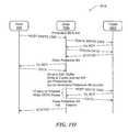
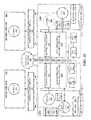
- FIGS. 19A to 19Iare sequence diagrams for a source side protection (SSP) active state.
- SSPsource side protection
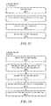
- FIGS. 20A to 20Bare sequence diagrams for a target side protection (TSP) active state.
- TSPtarget side protection
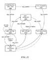
- FIG. 21is a flow diagram of an example of a process to complete initialization.
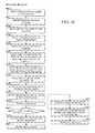
- FIG. 22is a flow diagram of an example of a process to perform a failover.
- FIG. 23is a block diagram of a continuous data protection system having logged access replication
- FIG. 24is a flow diagram for accessing an image on a replica and disabling image access
- FIG. 25is a state diagram for a splitter
- FIG. 26is flow diagram for production recovery
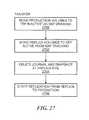
- FIG. 27is a flow diagram for failover
- FIG. 28is a block diagram of a continuous data protection system having logged access replication with a data protection appliance/agent forming a part of a storage array;
- FIG. 29is a schematic representation of a computer that can form a part of exemplary embodiments of the invention.
- BACKUP SITEa facility where replicated production site data is stored; the backup site may be located in a remote site or at the same location as the production site;
- DPAa computer or a cluster of computers that serve as a data protection appliance, responsible for data protection services including inter alia data replication of a storage system, and journaling of I/O requests issued by a host computer to the storage system;
- HOSTat least one computer or networks of computers that runs at least one data processing application that issues I/O requests to one or more storage systems; a host is an initiator with a SAN;
- HOST DEVICEan internal interface in a host, to a logical storage unit
- IMAGEa copy of a logical storage unit at a specific point-in-time
- INITIATORa node in a SAN that issues I/O requests
- JOURNALa record of write transactions issued to a storage system; used to maintain a duplicate storage system, and to rollback the duplicate storage system to a previous point-in-time;
- LOGICAL UNITa logical entity provided by a storage system for accessing data from the storage system
- LUNa logical unit number for identifying a logical unit
- PHYSICAL STORAGE UNITa physical entity, such as a disk or an array of disks, for storing data in storage locations that can be accessed by address;
- PRODUCTION SITEa facility where one or more host computers run data processing applications that write data to a storage system and read data from the storage system;
- SANa storage area network of nodes that send and receive I/O and other requests, each node in the network being an initiator or a target, or both an initiator and a target;
- SOURCE SIDEa transmitter of data within a data replication workflow, during normal operation a production site is the source side; and during data recovery a backup site is the source side;
- STORAGE SYSTEMa SAN entity that provides multiple logical units for access by multiple SAN initiators
- TARGETa node in a SAN that replies to I/O requests
- TARGET SIDEa receiver of data within a data replication workflow; during normal operation a back site is the target side, and during data recovery a production site is the target side;
- WANa wide area network that connects local networks and enables them to communicate with one another, such as the Internet.
- the methods and apparatus of exemplary embodimentsmay take the form, at least partially, of program code (i.e., instructions) embodied in tangible media, such as disks (element 5 in FIG. 1 ), CD-ROMs 6 , hard drives 7 , random access or read only-memory 8 , or any other machine-readable storage medium, including transmission medium.
- program codei.e., instructions
- tangible mediasuch as disks (element 5 in FIG. 1 ), CD-ROMs 6 , hard drives 7 , random access or read only-memory 8 , or any other machine-readable storage medium, including transmission medium.
- the mediacan include portions in different system components, such as memory in a host, an application instance, and or, a management station.
- the methods and apparatusmay be embodied in the form of program code that may be implemented such that when the program code is received and loaded into and executed by a machine, such as a computer, the machine becomes an apparatus for practicing the embodiments described herein.
- program codeWhen implemented on processor, the program code combines with the processor to provide a unique apparatus that operates analogously to specific logic circuits.
- the program code(software-based logic) for carrying out the method is embodied as part of the system described below.
- FIG. 1is a simplified illustration of a data protection system 100 .
- Shown in FIG. 1are two sites; Site I, which is a production site, on the right, and Site II, which is a backup site, on the left.
- the production siteis the source side of system 100
- the backup siteis the target side of the system.
- the backup siteis responsible for replicating production site data. Additionally, the backup site enables rollback of Site I data to an earlier point-in-time, which may be used in the event of data corruption of a disaster, or alternatively in order to view or to access data from an earlier point-in-time.
- a failovermay be performed in the event of a disaster at the production site, or for other reasons.
- Site I or Site IIbehaves as a production site for a portion of stored data, and behaves simultaneously as a backup site for another portion of stored data.
- a portion of stored datais replicated to a backup site, and another portion is not.
- the production site and the backup sitemay be remote from one another, or they may both be situated at a common site, local to one another.
- Local data protectionhas the advantage of so minimizing data lag between target and source, and remote data protection has the advantage is being robust in the event that a disaster occurs at the source side.
- the source and target sidescommunicate via a wide area network (WAN) 128 , although other types of networks are also adaptable for use.
- WANwide area network
- Each side of system 100includes three major components coupled via a storage area network (SAN); namely, (i) a storage system, (ii) a host computer, and (iii) a data protection appliance (DPA).
- the source side SANincludes a source host computer 104 , a source storage system 108 , and a source DPA 112 .
- the target side SANincludes a target host computer 116 , a target storage system 120 , and a target DPA 124 .
- a SANincludes one or more devices, referred to as “nodes”.
- a node in a SANmay be an “initiator” or a “target”, or both.
- An initiator nodeis a device that is able to initiate requests to one or more other devices; and a target node is a device that is able to reply to requests, such as small computer system interface (SCSI) commands, sent by an initiator node.
- a SANmay also include network switches, such as fiber channel switches.
- the communication links between each host computer and its corresponding storage systemmay be any appropriate medium suitable for data transfer, such as fiber communication channel links.
- the hostcommunicates with its corresponding storage system using small computer system interface (SCSI) commands.
- SCSIsmall computer system interface
- System 100includes source storage system 108 and target storage system 120 .
- Each storage systemincludes physical storage units for storing data, such as disks or arrays of disks.
- storage systems 108 and 120are target nodes.
- storage system 108exposes (e.g., makes available) one or more logical units (LU) to which commands are issued.
- LUlogical units
- storage systems 108 and 120are SAN entities that provide multiple logical units for access by multiple SAN initiators.
- Logical unitsare a logical entity provided by a storage system, for accessing data stored in the storage system.
- a logical unitis identified by a unique logical unit number (LUN).
- LUNunique logical unit number
- storage system 108exposes a logical unit 136 , designated as LU A
- storage system 120exposes a logical unit 156 , designated as LU B.
- LU Bis used for replicating LU A.
- LU Bis generated as a copy of LU A.
- LU Bis configured so that its size is identical to the size of LU A.
- storage system 120serves as a backup for source side storage system 108 .
- some logical units of storage system 120may be used to back up logical units of storage system 108 , and other logical units of storage system 120 may be used for other purposes.
- there is symmetric replicationwhereby some logical units of storage system 108 are used for replicating logical units of storage system 120 , and other logical units of storage system 120 are used for replicating other logical units of storage system 108 .
- System 100includes a source side host computer 104 and a target side host computer 116 .
- a host computermay be one computer, or a plurality of computers, or a network of distributed computers, each computer may include inter alia a conventional CPU, volatile and non-volatile memory, a data bus, an I/O interface, a display interface and a network interface.
- a host computerruns at least one data processing application, such as a database application and an e-mail server.
- an operating system of a host computercreates a host device for each logical unit exposed by a storage system in the host computer SAN.
- a host deviceis a logical entity in a host computer, through which a host computer may access a logical unit.
- host device 104identifies LU A and generates a corresponding host device 140 , designated as Device A, through which it can access LU A.
- host computer 116identifies LU B and generates a corresponding device 160 , designated as Device B.
- host computer 104is a SAN initiator that issues I/O requests (write/read operations) through host device 140 to LU A using, for example, SCSI commands. Such requests are generally transmitted to LU A with an address that includes a specific device identifier, an offset within the device, and a data size. Offsets are generally aligned to 512 byte blocks.
- the average size of a write operation issued by host computer 104may be, for example, 10 kilobytes (KB); i.e., 20 blocks. For an I/O rate of 50 megabytes (MB) per second, this corresponds to approximately 5,000 write transactions per second.
- System 100includes two data protection appliances, a source side DPA 112 and a target side DPA 124 .
- a DPAperforms various data protection services, such as data replication of a storage system, and journaling of I/O requests issued by a host computer to source side storage system data.
- data protection servicessuch as data replication of a storage system, and journaling of I/O requests issued by a host computer to source side storage system data.
- a DPAmay also enable rollback of data to an earlier point-in-time, and processing of rolled back data at the target site.
- Each DPA 112 and 124is a computer that includes inter alia one or more conventional CPUs and internal memory.
- each DPAis a cluster of such computers.
- Use of a clusterensures that if a DPA computer is down, then the DPA functionality switches over to another computer.
- the DPA computers within a DPA clustercommunicate with one another using at least one communication link suitable for data transfer via fiber channel or IP based protocols, or such other transfer protocol.
- One computer from the DPA clusterserves as the DPA leader.
- the DPA cluster leadercoordinates between the computers in the cluster, and may also perform other tasks that require coordination between the computers, such as load balancing.
- DPA 112 and DPA 124are standalone devices integrated within a SAN.
- each of DPA 112 and DPA 124may be integrated into storage system 108 and storage system 120 , respectively, or integrated into host computer 104 and host computer 116 , respectively.
- Both DPAscommunicate with their respective host computers through communication lines such as fiber channels using, for example, SCSI commands.
- DPAs 112 and 124are configured to act as initiators in the SAN; i.e., they can issue I/O requests using, for example, SCSI commands, to access logical units on their respective storage systems. DPA 112 and DPA 124 are also configured with the necessary functionality to act as targets; i.e., to reply to I/O requests, such as SCSI commands, issued by other initiators in the SAN, including inter alia their respective host computers 104 and 116 . Being target nodes, DPA 112 and DPA 124 may dynamically expose or remove one or more logical units.
- Site I and Site IImay each behave simultaneously as a production site and a backup site for different logical units.
- DPA 112 and DPA 124may each behave as a source DPA for some logical units and as a target DPA for other logical units, at the same time.
- host computer 104 and host computer 116include protection agents 144 and 164 , respectively.
- Protection agents 144 and 164intercept SCSI commands issued by their respective host computers, via host devices to logical units that are accessible to the host computers.
- a data protection agentmay act on an intercepted SCSI commands issued to a logical unit, in one of the following ways:
- a protection agentmay handle different SCSI commands, differently, according to the type of the command. For example, a SCSI command inquiring about the size of a certain logical unit may be sent directly to that logical unit, while a SCSI write command may be split and sent first to a DPA associated with the agent.
- a protection agentmay also change its behavior for handling SCSI commands, for example as a result of an instruction received from the DPA.
- the behavior of a protection agent for a certain host devicegenerally corresponds to the behavior of its associated DPA with respect to the logical unit of the host device.
- the associated protection agentsplits I/O requests issued by a host computer to the host device corresponding to that logical unit.
- the associated protection agentfails I/O requests issued by host computer to the host device corresponding to that logical unit.
- Protection agentsmay use any protocol suitable for data transfer within a SAN, such as fiber channel, or SCSI over fiber channel.
- the communicationmay be direct, or via a logical unit exposed by the DPA.
- protection agentscommunicate with their respective DPAs by sending SCSI commands over fiber channel.
- protection agents 144 and 164are drivers located in their respective host computers 104 and 116 .
- a protection agentmay also be located in a fiber channel switch, inside the storage system or in any other device situated in a data path between a host computer and a storage system.
- DPA 112acts as a source site DPA for LU A.
- protection agent 144is configured to act as a source side protection agent; i.e., as a splitter for host device A. Specifically, protection agent 144 replicates SCSI I/O requests. A replicated SCSI I/O request is sent to DPA 112 . After receiving an acknowledgement from DPA 124 , protection agent 144 then sends the SCSI I/O request to LU A. Only after receiving a second acknowledgement from storage system 108 will host computer 104 initiate another I/O request.
- DPA 112When DPA 112 receives a replicated SCSI write request from data protection agent 144 , DPA 112 transmits certain I/O information characterizing the write request, packaged as a “write transaction”, over WAN 128 to DPA 124 on the target side, for journaling and for incorporation within target storage system 120 .
- DPA 112may send its write transactions to DPA 124 using a variety of modes of transmission, including inter alia (i) a synchronous mode, (ii) an asynchronous mode, and (iii) a snapshot mode.
- DPA 112sends each write transaction to DPA 124 , receives back an acknowledgement from DPA 124 , and in turns sends an acknowledgement hack to protection agent 144 .
- Protection agent 144waits until receipt of such acknowledgement before sending the SCSI write request to LU A.
- DPA 112sends an acknowledgement to protection agent 144 upon receipt of each I/O request, before receiving an acknowledgement back from DPA 124 .
- DPA 112receives several I/O requests and combines them into an aggregate “snapshot” of all write activity performed in the multiple I/O requests, and sends the snapshot to DPA 124 , for journaling and for incorporation in target storage system 120 .
- DPA 112also sends an acknowledgement to protection agent 144 upon receipt of each I/O request, before receiving an acknowledgement back from DPA 124 .
- DPA 124While in production mode, DPA 124 receives replicated data of LU A from DPA 112 , and performs journaling and writing to storage system 120 . When applying write operations to storage system 120 , DPA 124 acts as an initiator, and sends SCSI commands to LU B.
- DPA 124undoes the write transactions in the journal, so as to restore storage system 120 to the state it was at, at an earlier time.
- LU Bis used as a backup of LU A.
- host computer 116should not be sending I/O requests to LU B.
- protection agent 164acts as a target site protection agent for host (Device B and fails I/O requests sent from host computer 116 to LU B through host Device B.
- target storage system 120exposes a logical unit 176 , referred to as a “journal LU”, for maintaining a history of write transactions made to LU B, referred to as a “journal”.
- journal LU 176may be striped over several logical units, or may reside within all of or a portion of another logical unit.
- DPA 124includes a journal processor 180 for managing the journal.
- Journal processor 180functions generally to manage the journal entries of LU B. Specifically, journal processor 180 (i) enters write transactions received by DPA 124 from DPA 112 into the journal, by writing them into the journal LU, (ii) applies the journal transactions to LU B, and (iii) updates the journal entries in the journal LU with undo information and removes already-applied transactions from the journal. As described below, with reference to FIGS. 2 and 3A-3D , journal entries include four streams, two of which are written when write transaction are entered into the journal, and two of which are written when write transaction are applied and removed from the journal.
- FIG. 2is a simplified illustration of a write transaction 200 for a journal.
- the journalmay be used to provide an adaptor for access to storage 120 at the state it was in at any specified point-in-time. Since the journal contains the “undo” information necessary to rollback storage system 120 , data that was stored in specific memory locations at the specified point-in-time may be obtained by undoing write transactions that occurred subsequent to such point-in-time.
- Write transaction 200generally includes the following fields:
- time stampwhich is the date & time at which the transaction was received by source side DPA 112 ;
- a write sizewhich is the size of the data block
- journal LU 176a location in journal LU 176 where the data is entered
- Write transaction 200is transmitted from source side DPA 112 to target side DPA 124 .
- DPA 124records the write transaction 200 in four streams.
- a first streamreferred to as a DO stream, includes new data for writing in LU B.
- a second streamreferred to as an DO METADATA stream, includes metadata for the write transaction, such as an identifier, a date & time, a write size, a beginning address in LU B for writing the new data in, and a pointer to the offset in the do stream where the corresponding data is located.
- a third streamreferred to as an UNDO stream
- a fourth streamreferred to as an UNDO METADATA
- an identifiera date & time
- a write sizea beginning address in LU B where data was to be overwritten
- each of the four streamsholds a plurality of write transaction data.
- write transactionsare received dynamically by target DPA 124 , they are recorded at the mid of the DO stream and the end of the DO METADATA stream, prior to committing the transaction.
- the various write transactionsare applied to LU B, prior to writing the new DO data into addresses within the storage system, the older data currently located in such addresses is recorded into the UNDO stream.
- a journal entrycan be used to “undo” a write transaction.
- old datais read from the UNDO stream in a reverse order, from the most recent data to the oldest data for writing into addresses within LU B. Prior to writing the UNDO data into these addresses, the newer data residing in such addresses is recorded in the DO stream.
- the journal LUis partitioned into segments with a pre-defined size, such as 1 MB segments, with, each segment identified by a counter.
- the collection of such segmentsforms a segment pool for the four journaling streams described hereinabove.
- Each such streamis structured as an ordered list of segments, into which the stream data is written, and includes two pointers—a beginning pointer that points to the first segment in the list and an end pointer that points to the last segment in the list.
- write transaction datais appended to the stream either at the end, for a forward direction, or at the beginning, for a backward direction.
- DPA 124As each write transaction is received by DPA 124 , its size is checked to determine if it can fit within available segments. If not, then one or more segments are chosen from the segment pool and appended to the stream's ordered list of segments.
- DO datais written into the DO stream, and the pointer to the appropriate first or last segment is updated. Freeing of segments in the ordered list is performed by simply changing the beginning or the end pointer. Freed segments are returned to the segment pool for re-use.
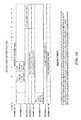
- journalingis thus advanced as indicated in TABLE below.
- Step 1The new data is written at the end of the DO stream, assuming a forward write direction, and corresponding metadata is written at the end of the DO METADATA stream.
- Step 2Data is read from the beginning of the DO stream, and corresponding metadata is read from the beginning of the DO METADATA stream.
- Step 3Old data to be overwritten is read from LU B. The location and size of such old data is determined from the DO METADATA stream.
- Step 4The old data is written at the end of the UNDO stream, and corresponding metadata is written at the end of the UNDO METADATA stream.
- Step 5The new data read at Step 2 is written into LU B, and the beginning and end pointers of the DO and DO METADATA streams are moved appropriately.
- Step 1Read the data and metadata from the end of the UNDO and UNDO METADATA streams.
- Step 2Read from LU B the data that is to be overwritten. The location and size of such data is determined from the UNDO METADATA stream.
- Step 3Write the data from Step 2 at the beginning of the DO stream, and update the DO METADATA stream accordingly.
- Step 4Write the data from Step 1 to LU B, and update the beginning and end pointers of the UNDO and UNDO metadata streams appropriately.
- a journal volumeincludes a plurality of segments from a segment pool, each segment including 20 data blocks.
- Stage #1Enter the three write transactions as journal entries in the journal LU.
- Stage #2Apply the first write transaction to LU B.
- Stage #3Apply the second write transaction to LU B.
- Stage #4Rollback the second write transaction, to recover data from an earlier point-in-time.
- the metadata corresponding to this transactionis written to the first block of Segment #2.
- the metadata corresponding to this transactionis written to the second block of Segment #2.
- the metadata corresponding to this transactionis written to the third block of Segment #2.
- the UNDO stream and the UNDO METADATA streamare empty.
- the journal and the four streams at the end of stage #1are illustrated in FIG. 3A .
- New data to be writtenis read from the journal LU at the offset and length indicated in the DO METADATA; namely, 15 blocks of data located in blocks 0-14 of journal volume Segment #1.
- old datais read from LU B at the offset and length indicated in the UNDO METADATA; namely, 15 blocks of data located in blocks 57-71 of LU B.
- the old datais then written into the UNDO stream in the journal LU, and the associated metadata is written into the UNDO METADATA stream in the journal LU.
- the UNDO datais written into the first 15 blocks of Segment #5, and the UNDO METADATA is written into the first block of Segment #6.
- journal LU Segment #1the new data that was read from blocks 0-14 of journal LU Segment #1 is written to blocks 57-71 of LU B.
- the beginning pointer for the DO streamis moved forward to block 15 of journal LU Segment #1, and the beginning pointer for the DO METADATA stream is moved forward to block 1 of journal LU Segment #2.
- the journal and the four streams at the end of stage #2are illustrated in FIG. 3B .
- 20 blocks of new dataare read from blocks 15-19 of journal LU Segment #1 and from blocks 0-14 of journal LU Segment #3.
- 20 blocks of old dataare read from blocks 87-106 of LU B.
- the old datais written to the UNDO stream in the last 5 blocks of journal LU Segment #5 and the first 15 blocks of journal LU Segment #7.
- the associated metadatais written to the UNDO METADATA stream in the second block of Segment #6.
- the list of segments in the UNDO streamincludes Segment #5 and Segment #7.
- the end pointer of the UNDO streamis moved to block 15 of Segment #7, and the end pointed of the UNDO METADATA stream is moved to block 2 of Segment #6.
- journal LU Segment #3is written into blocks 87-106 of LU B.
- the beginning pointer for the DO streamis moved forward to block 15 of journal volume Segment #3, and the beginning pointer for the DO METADATA stream is moved forward to block 2 of journal LU Segment #2.
- Segment #1is freed from the DO stream, for recycling within the segment pool, and the list of segments for the DO stream is changed to Segment #3 and Segment #4.
- the journal and the four streams at the end of stage #3are illustrated in FIG. 3C .
- the 20 blocks of data from area (b)are read from LU B and written to the beginning of the DO stream.
- the end pointer for the DO streamis set to block 15 of Segment #8.
- the list of segments for the DO streamis changed to Segment #3, Segment #4 and Segment #8.
- the metadata associated with the 20 blocks from area (b)is written to block 3 of Segment #2, and the end pointer of the DO METADATA stream is advanced to block 4 of Segment #2.
- journalis thus used to rollback LU B to the state that it was in at a previous point-in-time.
- the journalis also used to selectively access data from LU B at such previous point-in-time, without necessarily performing a rollback. Selective access is useful for correcting one or more files that are currently corrupt, or for simply accessing old data.
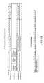
- FIG. 4is a simplified flowchart of a data protection method corresponding to TABLE IV.
- FIG. 4is divided into four columns. The leftmost column indicates steps performed by source side protection agent 112 , the middle left column indicates steps performed by source side DPA 144 , the middle right column indicates steps performed by target side DPA 124 , and the rightmost column indicates steps performed by target side protection agent 164 .
- Source Side Agent Intercept SCSI commands issued to LU A by source 144 side host via Device A(step 404).
- Replicate write commands, and route write commands to DPA(steps 408 and 412). Wait for first acknowledgement, from DPA (step 416), and then route replicate I/O command to LU A (step 420). Wait for second acknowledgement, from storage system (step 424), and then process next intercepted SCSI command (step 404).
- 112Format write command as write transaction, and send to target DPA (step 428). In synchronous mode, wait for acknowledgement from target DPA (step 432) and then send acknowledgement to agent (step 436).
- Target Side DPAReceive write transaction from source DPA (step 124 444). Enter write transaction in journal DO and DO METADATA streams (step 444), and send back acknowledgement to source DPA (step 448).
- Process journal entriesby applying them to LU B, and enter undo information in UNDO and UNDO METADATA streams (step 440).
- steps 432 and 436which do not have arrows connecting them, are not necessarily sequential. In a synchronous mode these steps are sequential, but in asynchronous mode and in snapshot mode they are not sequential.
- DPA 112may send an acknowledgement to protection agent 144 before receiving an acknowledgement back from DPA 124 .
- steps performed by target side DPA 124include two non-sequential groups; namely, (i) step 440 , and (ii) steps 444 and 448 .
- Recovery modeis generally triggered as a result of a disaster at the source side.
- the source side datamay become corrupt, or may not exist at all, in such case, after recovery is completed at the backup site, a user may perform a failover operation by switching the roles of the production site and backup site.
- the original backup sitebecomes a current production site, and the original production site becomes a current backup site.
- recovery modecan be triggered without a failover, in order to access data from a previous point-in-time.
- target site DPA 124While in recovery mode, target site DPA 124 continues to receive new write transactions from DPA 112 and enter them at the ends of the DO and DO METADATA streams. However, unlike production mode behavior, DPA 124 stops applying journal entries received from DPA 112 to LU B. Instead, DPA 124 uses the UNDO stream of the journal to rollback LU B, as described hereinabove.
- protection agent 164stops failing I/O requests issued by host computer 160 and begins redirecting them to DPA 124 .
- the processing of data by host computer 160 during recovery modeis referred to as “target side processing (TSP)”.
- journal processor 180uses two additional data streams, referred to as TSP DO and TSP METADATA streams.
- TSP DOWhen a TSP write command is received by DPA 124 , it is entered at the end of the TSP DO stream and the end of the TSP DO METADATA stream. Since TSP writes relate to the state of LU B after the rollback is complete, the TSP DO stream writes are only applied to LU B after rollback is complete.
- Journal processor 180applies TSP writes to LU B in a way similar to the way it applies write transactions deceiver from DPA 112 ; namely, journal processor 180 maintains the undo information for each write applied to LU B, in TSP UNDO and TSP UNDO METADATA streams.
- DPA 124When TSP read commands are received by target site DPA 124 , DPA 124 returns the data to be read by identifying locations of the read command, and finding the most recent TSP write command or commands that were applied at these locations. The data is searched for (i) first in the TSP DO stream, and (ii) then in the journal UNDO data that was not yet applied to LU B and (iii) finally, if the data was not found in (i) and (ii), then the data is taken from LU B itself. In order to perform such a search efficiently, DPA 124 generates and stores in its memory a virtual image of the UNDO METADATA storage locations by using an efficient data structure, such as a binary search tree.
- an efficient data structuresuch as a binary search tree.
- TSP writes that were performed during the rollbackare applied to LU B, and DPA 124 begins applying TSP writes synchronously; i.e., TSP writes are applied to LU B when they are received by DPA 124 , without keeping them in the TSP DO stream.
- TSP writesare applied to LU B when they are received by DPA 124 , without keeping them in the TSP DO stream.
- a read commandis received after rollback is complete, it is sent directly to LU B instead of being redirected through DPA 124 .
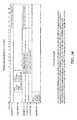
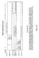
- FIGS. 5A, 5B, 6A and 6Bare simplified flowcharts of data protection methods corresponding to TABLES V and VI, respectively.
- FIGS. 5A, 5B, 6A and 6Bare divided into four columns. The leftmost column indicates steps performed by target side protection agent 164 , the middle left column indicates steps performed by target side DPA 124 , the middle right column indicates steps performed by source side DPA 112 , and the rightmost column indicates steps performed by source side protection agent 144 .
- Target Side Agent Intercept SCSI commands issued to LU B(step 576). 164 Redirect commands to DPA (step 580).
- Target Side DPAUse UNDO stream of journal to roll back target 124 storage system (step 540).
- Continue receiving write transactions from DPA 112 and enter these transactions into DO and DO METADATA streams without applying them to LU B(step 548).
- Enter TSP write transactions to TSP DO and TSP DO METADATA streams(step 564).
- Create a virtual image, to reply to read commands issued during the recovery process(step 572).
- Source Side DPAAs in production mode. 112
- Source Side AgentAs in production mode. 144
- Target Side Intercept SCSI commands issued to LU B(step 664).
- Agent 164Redirect write transactions to DPA (step 672), and route read commands directly to LU B (step 680).
- Target Side Apply TSP write transactions to LU Bin the same DPA 124 manner that write transactions received from DPA 112 are applied in production mode; i.e., by entering data into TSP UNDO and TSP UNDO METADATA streams (step 640). Enter DO information and write transactions received from DPA 112 into DO and DO METADATA streams, without applying them to LU B (step 644). Apply TSP write transactions to LU B as they are received. (step 656).
- DPA 112Source Side As in production mode.
- Agent 144Redirect write transactions to DPA (step 672), and route read commands directly to LU B (step 680).
- Target Side Apply TSP write transactions to LU Bin the same DPA 124 manner that write transactions received from DPA 112 are applied in production mode; i
- the steps performed by target side DPA 124include three non-sequential groups; namely, (i) step 540 , (i) steps 548 and 552 , and (iii) steps 556 , 560 , 564 , 568 and 572 .
- target side DPAperforms three non-sequential groups of steps; namely, (i) step 640 , (ii) steps 644 and 648 , and (iii) steps 652 , 656 and 660 .
- FIG. 7is a simplified illustration of a time-line for tracking new processing of old data.
- FIG. 7illustrates journal processor 180 bringing the timeline hack to a previous time, TOLD, and journal processor 180 applying TSP writes to bring the timeline forward from time TCURRENT to time TNEW.
- current data at time (1)is rolled back to old data at time (2).
- the rolled back databecomes the image upon which target side processing advances to new data at time (3); i.e., the target side processing is applied to data (2) and not to data (1).
- the data at time (1)is a common image for LU A and LU B at the same point-in-time, TCURRENT.
- the data at time (2)is a common image for LU A and LU B at time TOLD.
- Rolled back data at time (2)may be processed by TSP writes, while at the same time current data at time (1) is being processed by source side writes.
- the dataevolves along the path from time (2) to time (3) as it is processed by the target side, and along the path from time (2) to time (4) as it is processed by the source side.
- the data images at the source and target sides at time TNEWare thus different.
- the usermay (i) return to a normal production mode, or (ii) perform a failover by switching the replication direction.
- LU Bis rolled back to its state at time (2), and the write transactions along the path from (2) to (4) are applied to LU B, so as to bring LU B to the same image as LU. A.
- LU Bis maintained at its state at time (3), and its data is copied from the target side to the source side so as to bring LU A to the same image as LU B.
- the state of the target side storageis substantially identical to the state that LU A was in at an earlier point-in-time.
- the state of LU Bis then in a new state that is different from the earlier state of LU A.
- DPA 124undoes the TSP writes that were written to LU B using the TSP undo stream, and then returns to its normal production mode and begins applying the data that was written into the DO stream.
- the DO streamincludes all write transactions that were undone while LU B was rolled back.
- the DO streamincludes new journal entries that were received from DPA 112 while DPA was in recovery mode.
- protection agent 164returns to its production mode by beginning to fail I/O requests issued by host 116 .
- the userwants to perform a failover; i.e., to make LU B in its current state a production LU and to ensure that LU A is a copy of LU B.
- a failoveri.e., to make LU B in its current state a production LU and to ensure that LU A is a copy of LU B.
- the write transactions in the DO stream that correspond to a point-in-time subsequent to the recovered point-in-timeare ignored.
- the TSP writes that were applied to LU B during the recovery processare applied to LU A.
- the replication directionchanges. Specifically, DPA 124 and protection agent 164 begin behaving in accordance with source site behavior, and DPA 112 and protection agent 144 begin behaving in accordance with target site behavior.
- the source sidein order to provide failover capability, in which the roles of the production site and the backup site are switched, it is desirable that the source side has the necessary system components to function as a target side, and vice versa.
- the source sideincludes its own journal LU 184 and journal processor 188 , as indicated with dotted lines in FIG. 1 .
- FIG. 8is a simplified illustration of a 5-stage journaling process for continuous data replication.
- the five steps shown in FIG. 8correspond respectively to the five steps listed in TABLE I.
- FIG. 8only shows three meta-data elements; namely, a size, a journal address and a storage address.
- the meta-data in the DO METADATA and UNDO METADATA streamsincludes an ID, a time, and other attributes.
- the meta-data for each transactionis of a fixed size, typically 30 bytes.
- the raw datavaries in size, typically averaging around 10 KB per transaction.
- step 2may be skipped.
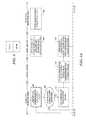
- FIG. 9is a simplified illustration of a 4-stage journaling process for continuous data replication, for use when an I/O data rate is low.
- the first step in FIG. 9copies the write transaction to the end of the DO stream and the end of the DO METADATA stream, as in the 5-stage journaling process.
- the 4-stage journaling processtakes advantage of the fact that the write transaction that was just received at the backup site is still resident in memory. For this write transaction, steps 3-5 are performed, as indicated in FIG. 9 .
- the write transactionis written into the end of a queue in memory.
- the queue in memoryis handled similar to the way the DO stream is handled; namely, each received write is appended to the end of the queue, and when a write transaction is distributed according to steps 3-5, a subsequent write transaction is taken from the be inning of the queue. Effectively, the queue corresponds to a cached DO stream.
- the 4-stage journaling processis used until the queue in memory is full, at which point the normal 5-stage journal processing is resumed. Also in the event of a disaster, the normal 5-stage journal processing is resumed. En order to resume the 5-stage journal processing, it is important to identify the last write in the DO stream that was written. As such, even during the 4-stage journal processing, the pointers to the first and last write transactions in the DO stream are updated.
- the normal 5-stage modemay be switched to a faster 3-stage mode whenever the DO stream reaches a large percentage of its maximum capacity, typically 80%.
- the faster 3-stage modeis switched back to the normal 5-stage mode whenever the DO stream is reduced to a smaller percentage of its maximum capacity, typically 75%.
- the 3-stage modeeliminates steps 3 and 4 from the normal mode; namely, the steps that record the UNDO information. As such, rollback of the backup storage unit to its state at the times of those transactions processed with the 3-stage mode is not possible.
- FIG. 10is a simplified illustration of a 3-stage journaling process for continuous data replication, for use when the DO stream is near its maximum capacity.
- One data replication strategyis the set of automated rules for controlling when a data replication system transitions between 5-stage, 4-stage and 3-stage journal processing.
- transitions from 5-stage to 3-stage journaling, and from 3-stage back to 5 stage journalingmay be controlled based on the current size of the DO stream.
- Transitions from 5 stage to 4-stage journalingmay be automated to occur when the beginning and end of the DO stream are close; and transitions from 4-stage back to 5-stage journaling may be automated to occur when the memory queue reaches its capacity.
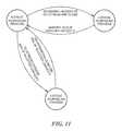
- FIG. 11is a simplified state diagram of transitions between 5-stage, 4-stage and 3-stage journal processing. Shown in FIG. 11 are three nodes, representing each of the journaling processes, and directed edges between the nodes corresponding to rules that govern transitions therebetween. As shown in FIG. 11 , a 5-stage to 3-stage transition occurs when the size of the DO stream exceeds 80% of its allotted capacity, and a 3-stage to 5-stage transition occurs when the size of the DO stream falls under 75% of its allotted capacity. Similarly, a 5-stage to 4-stage transition occurs when the beginning and end of the DO stream are close; and a 4-stage to 5-stage transition occurs when the memory queue reaches its capacity.
- 4-stage journalingenables a data replication system to keep pace with higher I/O rates than can be handled when using 5-stage journaling. If the system is currently using 5-stage journaling and the I/O rate is higher than can be handled, a lag increases until the system necessarily transitions to the 3-stage journaling process. However, if the system can catch up with the lag, empty the DO stream and transition to a 4-stage journaling process, then the system can accommodate higher I/O rates before transitioning back to the 5-stage journaling process.
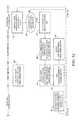
- FIG. 12is a simplified illustration of a variant of the three-stage journaling process shown in FIG. 10 .
- the alternative 3-stage journalingproceeds according to the last three stages of the 4-stage journaling process. That is, the stage of writing to the DO stream is skipped within 4-stage journaling, for the alternative embodiment of 3-stage journaling.
- the backup site DPA(element 124 of FIG. 1 ) can return an acknowledgement to the production site DPA (element 112 of FIG. 1 ) immediately after the first stage, when the write transaction is written to the DO stream.
- the backup site DPAmust wait until the write transaction is written to storage, before it can return an acknowledgement to the production site DPA. Since the last three stages of 4-stage journaling can be performed in a separate thread than the thread that performs the first stage, the alternative 3-stage journaling may result in a longer time lag between the source and target sites.
- a mapis generated to identify changes between a current volume state and the most updated state.
- the mapis used to enable signature testing only on locations where the volume is updated.
- a delta marker streamcontains the locations that may be different between the latest I/O data which arrived to the remote side (the current remote site) and the latest I/O data which arrived at the local side.
- the delta marking streamincludes metadata of the differences between the source side and the target side. For example, every I/O reaching the data protection appliance for the source 112 is written to the delta marking stream and data is freed from the delta marking stream when the data safely arrives at both the source volume of replication 108 and the remote journal 180 (e.g. DO stream). Specifically, during an initialization process no data is freed from the delta marking stream; and only when the initialization process is completed and I/O data has arrived to both local storage and the remote journal data is I/O data from the delta marking stream freed.
- the initialization processstarts by merging delta marking streams of the target and the source so that the delta marking stream includes a list of all different locations between local and remote sites. For example, a delta marking stream at the target might have data too if a user has accessed an image at the target site.
- the initialization processcreates one virtual disk out of all the available user volumes.
- the virtual spaceis divided into a selected number of portions depending upon the amount of data needed to be synchronized.
- a list of ‘dirty’ blocksis read from the delta marker stream that is relevant to the area currently being synchronized to enable creation of a dirty location data structure.
- the systembegins synchronizing units of data, where a unit of data is a constant amount of dirty data, e.g., a data that needs to be synchronized.
- the dirty location data structureprovides a list of dirty location until the amount of dirty location is equal to the unit size or until there is no data left.
- the systembegins a so-called ping pong process to synchronize the data.
- FIG. 13shows an exemplary synchronization environment in accordance with exemplary embodiments.
- a first volume 700such as a local volume (e.g., at the source side) is synchronized with a second volume 602 , such as a remote volume (e.g., at the target side).
- a pinger module 704 on the local appliance 112 and a ponger module 706 on the remote appliance 124examine data and selectively exchange information to efficiently perform initialization for making data in a remote site identical to data in a local site before replicating data in the remote volume.
- the local user volume 700interacts with the pinger module 704 , which is coupled to a WAN 707 .
- the remote user volume 702interacts with the ponger module 706 .
- the pinger module 704reads data from a part of the local user volume 700 , signs the data (i.e. calculates a hash function of the data), and transmits the signature 708 to the ponger module 706 .
- the ponger module 706reads from the same part of the remote user volume 702 , signs the data, and compares the signatures.
- the ponger module 706transmits to the pinger module 704 addresses 710 of the user volume blocks where data differs. If there are differences, the pinger module 704 again reads the data from the local user volume 700 and transmits the data 716 to the distributor 712 on the remote side through a transmitter 711 .
- the distributor 712processes initialization data from the pinger module 704 , which is written to the DO stream 750 while application data arriving in the local site is written to a temporary initialization stream 752 .
- the initialization stream 752 and the DO stream 750are united to create an initialization snapshot and then the data is written to the user volume 700 .
- a signatureis used only if calculation of data reduction shows that signature usage saves bandwidth.
- the signature replacement processcan be layered (i.e., calculate all the signature for the unit but at the beginning send only aggregated signatures from local to remote e.g., send a signature for every 256 blocks, then on the remote if the signature on all 256 block is different, check only for the block signature on one block level).
- signaturescan be used only if remote user volumes are updated with the latest image.
- Conventional systemsdo not use signatures if the remote copy is not updated to the last image.
- the remote copymay not be the latest for a number of reasons, such as a user being mounted on a point-in-time image at the remote site, a stoppage of the initialization process, and period in which the system could not handle I/Os in five phase distribution so that a gap is created between the latest image in the journal and the latest image in the user volume, as described in detail above.
- a dirty location mapis created to identify locations for which distribution from the DO stream to the UNDO stream has not yet taken place (or data written during logged access mode to the TSP stream).
- the dirty location mapis generated from the DO metadata stream and the TSP metadata stream.
- the systemcan begin using data signatures to compare data between local and remote volumes. Signatures are not used for locations in the dirty location map.
- the dirty location mapis updated with any I/O write operations.
- FIG. 15shows an example of a dirty location map generation.
- a first volume V 1has blocks 1-6 and a second volume V 2 has corresponding blocks 1-6. It is determined that blocks 1, 2, and 3 of the local and remote volumes have differences that need to be addressed for initialization.
- the DO streamcontains a series of entries including an entry for block 2, which has not yet been distributed.
- a corresponding entry for block 2is contained in the DO metadata stream.
- block 2of differing blocks 1-3, has an entry in the DO stream, and thus, signatures should not be used for block 2.
- a dirty location map(DLM) is generated from the DO metadata stream. Only the entry for block 2 is set for blocks 1-6 of the volumes since block 2 is the only block contained in the DO metadata stream. In this example, a logical ONE is set in the dirty location map DLM for locations having entries in the DO stream.
- Block 2has an entry in the DO stream, which is reflected in the dirty location bit map DLM.
- a data signature for block 2should not be sent.
- data signaturescan be sent for blocks 1 and 3.
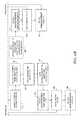
- FIG. 16shows an exemplary process, an initialization process 790 , for implementing selective signature transmission for initialization in a continuous data protection system in accordance with exemplary embodiments described herein.
- a process step 800the initialization process 790 begins to synchronize first and second volumes from a local (source) and a remote (target) sides.
- process step 802differences between blocks in a first volume and corresponding blocks in a second volume are identified.
- process step 804a data stream containing data that has not been distributed to/from the data volumes is examined to identify locations for data distribution. In an exemplary embodiment, the DO metadata stream is examined to identify the locations.
- a dirty location mapis created in which locations contained in the DO metadata stream are flagged.
- the dirty location mapprovides a bitmap where each bit corresponds to block. In other embodiments, a bit corresponds to a number of disk blocks.
- the dirty location mapis used such that for flagged locations data signatures are not sent during the initialization process. Data signatures can be used for non-flagged locations.
- data signaturesare sent for locations not flagged in the dirty location map as part of the volume synchronization process.
- the initialization processcan occur while a user is currently mounting an old point-in-time.
- datais distributed from the undo stream to the DO stream, this process can happen while the initialization process is actually running, meaning, the do stream actually grows and contains more data during the initialization.
- the user volumegets less updated and the system needs to add the locations to the dirty location bitmap, so every redo data written to the DO stream updates the bitmap
- the protection agentsare located at the host. It would be beneficial for these splitters to be located at the storage array 108 or 120 since the array could come with a splitter pre installed.
- the number of hostsis significantly higher than the number of storage arrays. Thus, it is easier to manage the splitter at the storage array than at the host. Also, since the number of software components available for the storage arrays is much smaller, it is easier to make a splitter more stable in the storage array. For example, each system can have different device drivers installed which are not compatible with a protection agent located at the host. However, placing a splitter at the storage array is non obvious and difficult to develop.
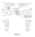
- a data protection system 1700includes the source-side host 104 ′ similar to source-side; host 104 but without the protection agent 144 .
- the system 1700also includes a source side storage 108 a , similar to the source-side storage 108 but with a splitter 1702 (also referred to herein as an ORS (Open Replicator Splitter) splitter), a cache 1704 , and a store and forward (S&F) buffer 1706 .
- the system 1700further includes a DPA 112 a similar in functionality to the DPA 112 , for example and includes a journal processor 188 .
- the source sidemay include one or more storage arrays like array 108 a.
- the system 1700further includes a target side storage 124 a , similar to the target side storage 124 but with a splitter 2002 (an ORS splitter), a cache 2004 , and a store and forward (S&F) buffer 2006 .
- the target sidemay have a different splitter type, for instance, a host splitter or a switch based splitter.
- the system 1700further includes a DPA 124 a similar in functionality to the DPA 124 , for example and includes a journal processor 176 .
- the data protection system 1700further includes a first cluster of DPAs which includes the DPA 112 a as well as a DPA 1121 and a DPA 112 c and a second cluster of DPAs which includes DPA 124 a as well as a DPA 124 b and a DPA 124 c.
- the DPAs 112 a - 112 care connected to a storage array 108 a through a switch (not shown) and DPAs 112 a - 112 c are connected to a storage array 120 a through a switch (not shown).
- the DPAs in the first or second clusterare connected to the same one or more than one storage array in a storage area network.
- Each of the DPAs 112 a - 112 cis connected to the DPAs 124 a - 124 a through the WAN 128 .
- the splitter- 1702may be used to replicate data through the DPAs 112 a - 112 c asynchronously or synchronously.
- the splitter 1702can also be used in failover.
- the splitterfunctions in at least two modes.
- a first modea source side protection (SSP) mode, is when the source side data is mirrored and a second mode, a target side protection (TSP) mode, is when the target side is used to access a point-in-time.
- SSPsource side protection
- TSPtarget side protection
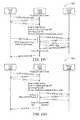
- the I/OsWhen an I/O arrives to a volume (e.g., a volume V (not shown)) in the storage array 108 a which has the splitter 1702 in an SSP active state (e.g., SSP active state 1806 in FIG. 18 ), the I/Os will be sent to the DPA (e.g., DPA 112 a ) exposing (e.g., making available) the target (e.g., a LUN V′(not shown)) to the splitter 1702 .
- the DPA 112 awill mirror the I/O metadata to another DPA (e.g., DPA 112 b or 112 c ).
- the DPA 112 awill send a transfer ready command to the splitter 1702 and the splitter 1702 will then send the I/O write data to LUN V′ exposed by the DPA 112 a .
- data arrivesit will be handled as previously described (see, for example, FIGS. 1 to 16 ) depending on the replication mode (e.g., synchronous mode, asynchronous mode, snapshot mode and so forth), and journaled at the journal 176 at the replication site by the DPA 124 a as also described above.
- the replication modee.g., synchronous mode, asynchronous mode, snapshot mode and so forth
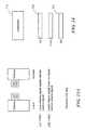
- the ORS splitter 1702has at least the following modes:
- CONTINUOUS_PUSHIn this mode there is a device (e.g., LUN A 136 ) and the data of the device is pushed continuously to another device (e.g., LUN B ( 156 )). Any I/Os written to LUN A will be written by the ORS splitter to the LUN B while in continuous push mode.
- the ORS splitterincludes a protection bitmap, which includes a bit for every track (64 KB).
- the ORS splittere.g., the splitter 1702
- the ORS sessionwill fail and all I/Os will be tracked in the protection bitmap.
- the I/Os to LUN Awill continue to be served with no disruption.
- the continuous push modecan work in two replication modes:
- ALPO(always push old data) mode: In this mode, there is a production device (e.g., LUN A) and a target device (e.g., LUN B). For every write arriving to LUN A, at an offset x of a size y, the current data at the offset x of the size y will be pushed to LUN B (exposed by the remote site DPA). When the I/O transfer to the LUN B is complete, the storage array 108 a will send a transfer ready message to the host 104 ′ writing to LUN A and the new data will be written to LUN A.
- LUN Aproduction device
- LUN Btarget device
- an ORS sessionis a connection between a target and a source LUN.
- the ORS sessioncan be in one of the following modes:
- SYNC_IN_PROGRESS—ORS sessionis activated, i.e., a foreground copy is active (every I/O reaching the source device is pushed to the target device), the protection bit map is not empty so data is being copied in the background from the source LUN to the target LUN.
- SYNCHRONIZED—ORS sessionis activated, i.e., the foreground copy is active and all the data marked dirty in the protection bit map was pushed to the target device.
- Foreground copymeans that at any host the I/Os are being pushed to the target device; and background copy means that when there are dirty locations in the protection bitmap the I/Os are being pushed to the target device) any IO to the device is tracked in the protection bitmap.
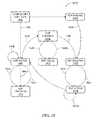
- a state diagram 1800indicates various states of the splitter 1702 .
- the statesinclude but are not limited to a configured state 1802 , a TSP passive state 1804 , a SSP active state 1806 , an SSP draining state 1808 , an SSP failed state 1810 , a TSP inactive state 1812 , an SSP tracking state 1814 and a TSP active state 1816 . If the source device is on the storage array and is the source device for ORS, then DPA 112 will expose a target device which will be target for the ORS session.
- the DPA 112 awill send the I/Os to the remote DPA 124 a , and I/Os will be written to the final target device on the storage array 120 on the remote site which is the target of replication as described in FIGS. 1 to 16 .
- the configured state 1802indicates that a replication session in the splitter 1702 is configured (e.g., by a DPA) for the TSP and SSP modes.
- the sessionincludes a source device (e.g., a device in the storage array) and a target device (e.g., a virtual device which the DPA will expose and will be used in order to replicate data from the source device on the array to a target device on another storage array).
- a target device for the ORS splitter 1702which is a virtual device, and there is the real target device which the ORS splitter 1702 is not aware of and can reside on a different site.
- the splitter 1702can transition from the configured state 1802 to the SSP active state 1806 through the use of a SSP activate command (e.g., issued by DPA 112 a ) ( 1830 ).
- a SSP activate commande.g., issued by DPA 112 a
- the DPA 112 aperforms the following:
- the splitter 1702can also transition from the configured state 1802 to the TSP passive state 1804 through a TSP passive command 1804 (e.g., issued by the DPA 112 a ) which sets the source device to a passive mode which means reads and write from the hosts (except the DPA 112 a , 112 b , 112 c ) to the device are failed but the device can be seen by the host 104 ′ and respond to SCSI inquiries ( 1832 ).
- the target deviceis passive and no I/Os can be sent to the device, except I/Os created by the DPA.
- the splitter 1702transitions from the TSP passive state 1804 to the TSP inactive state 1812 through a TSP inactivate command (e.g., issued by DPA 112 a ) ( 1834 ).
- a TSP inactivate commande.g., issued by DPA 112 a
- the device in the storage arrayis passive.
- the DPAexposes the target device for the ORS session and the ORS splitter 1702 discovers the target device.
- the splitter 1702transitions from the TSP inactive state 1812 to the TSP active 1816 through a TSP activate command ( 1836 ).
- TSP active state 1816the target device is active.
- the hostcan now generate I/Os to the ORS source device.
- the ORS source deviceis the target device for the total replication and TSP access happens at the remote site during replication.
- replicationcan have just one type of splitter on one of the replication sites, i.e., an ORS splitter, and another type of splitter on the other site (for instance, a host splitter such, as protection agent 144 ).
- the splitter 1702can remain in the TSP active state 1816 if there is a write I/O failure ( 1840 a ).
- the ORS splitterwill rediscover the path to the DPA exposed LUN, so that if the DPA exposing the LUN fails then another DPA will expose the LUN and the ORS splitter will rediscover it and be able to continue writing.
- the splitter 1702can transition back to the TSP inactive state 1812 if a TSP deactivate command is executed ( 1842 ) or transition to the SSP active command 1806 if a SSP switch is activated ( 1844 ).
- the splitter 1702can transition to the SSP draining state 1808 when a SSP drain command is executed ( 1846 ). In order to move to SSP draining state 1808 ,
- the splittertransitions from the SSP draining state 1808 to the SSP failed state 1810 ( 1840 b ).
- the target deviceis passive, continuous push is active but pushing the data has failed, (meaning the ORS session state has failed).
- the SSP splitter 1702transitions from the SSP failed state 1810 back to the SSP draining state 1808 ( 1848 ), in one example, the ORS splitter will first try to re-discover a path to the volume exposed by the DPA. If a path is found, the ORS splitter 1702 will move to the SSP draining state 1808 ; otherwise, it will remain in the SSP failed state 1810 . If a TSP switch command is executed, the splitter 1702 transitions from the SSP draining state 1808 to the TSP inactive state 1812 ( 1850 ). In one example, the TSP switch command is executed if the ORS session is in the SYNCHRONIZED mode.
- the splitter 1702can transition to the SSP tracking state 1814 if an SSP track command is executed ( 1852 ) (in this case ORS session state move to stopped mode) or if there is a write I/O failure ( 1840 c ), the ORS splitter 1702 determines that an I/O failed based on the replication mode.
- the ORS splitter 1702will try to write or track data to the DPA exposed LUN for 11 sec, for example. If it does not succeed, the host write is accepted and ORS session goes to the FAILED mode and tracks new host writes, and in asynchronous mode ORS will try to write to DPA exposed LUN once and if not successful session goes to the FAILED mode and tracks host writes.
- the total state of the ORS splitteris the SSP tracking state.
- the splitter 1702can transition from the SSP tracking state 1814 back to the SSP active state 1806 if a SSP recreate command is executed ( 1854 ).
- the recreate commandwill rediscover the path to the device exposed by the DPA, if the path is found the splitter will move to the SSP active state 1806 otherwise it will remain in the SSP tracking state 1814 .
- the rediscoveryis used in case a path to the DPA is lost and another path is needed or if the DPA has failed and another DPA now exposes the LUN.
- the target deviceis active, continuous push is active but pushing the I/O data is stopped or failed, and any I/O arriving to the source device of the ORS is tracked in the protection bitmap.
- the ORS splitter 1702 in the storage array 108 aremains in the SSP active state 1806 if a set replication mode command (which changes the mode to synchronous or asynchronous) is executed ( 1856 ).
- the ORS splitter 1702 in storage array 108 a in conjunction with the host 104 ′ and a virtual target 1900 exposed by the DPAcan perform a number of different processes (e.g., the processes 1902 - 1918 ) while the splitter is in the SSP active state 1806 .
- the splitter 1702runs on the storage array 108 a and any I/Os transferred to a volume where ORS is configured will be sent to the ORS target volume 1900 exposed by the DPA 112 a (for every volume where the ORS splitter is configured, another volume with the same size and characteristics will be exposed by the DPA).
- the array 108 areceives the I/Os. If the ORS session is configured it will handle the I/Os as described in FIGS. 19A-19I .
- write commandsare standard SCSI write commands.
- a process 1902depicts using the storage array 108 a when the ORS splitter 1702 is not configured.
- the host 104 ′sends a host write command (HOST WRITE CMD) to the storage array 108 a which returns a transfer ready message (TX RDY).
- the host 104 ′then sends the data to the array 108 a which writes the data in a the S&F buffer 1706 in the storage array 108 a , writes to the cache 1704 in the storage array 108 a and sets write pending (WP).
- the array 108 areturns a status message to the host 104 ′.
- a process 1904is an example of a process used when the array 108 a , when ORS session is configured and is in the SSP active state 1806 .
- the protection bitis clear.
- the host 104 ′sends a host write command (HOST WRITE CMD) to the array 108 a which returns a transfer ready message (TX RDY).
- the host 104 ′then sends the data to the array 108 a which writes the data in the S&F buffer 1706 , writes to the cache 1704 and sets WP.
- the protection bitis set.
- the ORS continuous push splitter 1702 in the storage array 108 asends the host write command to the target 1900 exposed by the DPA 112 a which returns a transfer ready message to the ORS splitter 1702 .
- the ORS splitter 1702sends the data to the target 1900 , which returns a status message when the data is stored on the target 1900 .
- the ORS splitter 1702returns a status message to the host 104 that data transfer is complete. The protection bit is then cleared.
- a process 1906is an example of a process used when the ORS splitter 1702 in array 108 a is in the SSP active state 1806 and an abort command is sent by the host 104 ′.
- the protection bitis clear.
- the host 104 ′sends a host write command (HOST WRITE CMD) to the storage array 108 a which returns a transfer ready message (TX RDY).
- the host 104 ′then sends the data to the splitter 1702 which writes the data in the S&F buffer 1706 , writes to the cache 1704 and sets WP.
- the protection bitis set.
- the ORS splitter 1702 in the array 108sends a host write command to the target 1900 exposed by DPA 112 a which returns a transfer ready message to the splitter 1702 .
- the splitter 1702 in the array 108 asends the data to the target 1900 exposed by DPA 112 a .
- the host 104 ′sends an abort command (ABTS CMD) during the Write transfer phase
- the splitter 1702sends an abort command to the target 1900 .
- the target 1900returns an abort status message (ABTS STATUS) to the splitter 1702 in the array 108 a .
- the protection bitremains set and the splitter 1702 in storage array 108 a sends an abort status message (ABTS STATUS) to the host 104 ′.
- the ORS sessionthen moves to SSP tracking state 1814 .
- a process 1908is an example of a process used when the ORS splitter 1702 in the array 108 a is in the SSP active state 1806 and data transfer times out.
- the protection bitis clear.
- the host 104 ′sends a host write command (HOST WRITE CMD) to the splitter 1702 which returns a transfer ready message (TX RDY).
- the host 104 ′then sends the data to the storage array 1700 which writes the data in the S&F buffer 1706 , writes to the cache 1704 and sets WP.
- the protection bitis set
- the ORS splitter 1702 in array 108 asends a host write command to the target 1900 exposed by the DPA 112 a which returns a transfer ready message to the splitter 1702 .
- the splitter 1702sends the data to the target 1900 . If the write transfer to the target 1900 times out (e.g., after 15 seconds) without completing the data transfer to the target 1900 , the protection bit remains set and the ORS session fails, and moves to the SSP tracking state 1814 .
- the storage array 108 asends a status message to the host 104 ′.
- a process 1910is an example of a process used when the ORS splitter 1702 in storage array 108 a is in the SSP active state 1806 and initially, the protection bit is set.
- the host 104 ′sends a host write command (HOST WRITE CMD) to the splitter 1702 .
- the splitter 1702sends a track write command (TRACK WRITE CMD) (i.e., the data currently on the storage for the track, e.g., all the 64 KB of the track) to the target 1900 exposed by the DPA, which returns a transfer ready (TX RDY) message.
- TX RDYtransfer ready
- the ORS splitter 1702 in storage array 108 asends track data to the target 1900 exposed by DPA 112 a , which returns a status message to the splitter 1702 and the protection bit cleared.
- the storage array 108 areturns a transfer ready message (TX RDY).
- the host 104then sends the data to the splitter 1702 which writes the data in the S&F buffer 1706 , writes to the cache 1704 and sets WP.
- the protection bitis set.
- the ORS splitter 1702 in the array 108 asends a host write command to the target 1900 which returns a transfer ready message to the splitter 1702 .
- the splitter 1702sends the data to the target 1900 exposed by the DPA 112 a .
- the target 1900sends a status message to the ORS splitter in storage array 108 a .
- the storage array 108 asends a status message to the host 104 and the protection bit is cleared.
- a process 1912is an example of a process used when the ORS splitter in storage array 108 a is in the SSP active state 1806 and an abort command is received during track write.
- the host 104 ′sends a host write command (HOST WRITE CMD) to the splitter 1702 .
- the splitter 1702sends track write command (TRACK WRITE CMD) to the target 1900 exposed by DPA 112 a , which returns a transfer ready (TX RDY) message.
- TX RDYtransfer ready
- the ORS splitter 1702 in storage array 108 asends track data to the target 1900 .
- ABS CMDabort command
- the ORS splitter 1702 in storage array 108 asends an abort command (ABTS CMD) to target 1900 exposed by DPA 112 a .
- the target 1900returns an abort status message (ABTS STATUS) to the splitter 1702 .
- the protection bitremains set and the storage array 108 ′ sends an abort status message (ARTS STATUS) to the host 104 ′.
- the splitter 1702moves to the SSP tracking state 1814 .
- a process 1910is an example of a process used when the ORS splitter 1702 in the storage array 108 a is in the SSP active state 1806 and an abort command is received during the host data transfer.
- the protection bitis set.
- the host 104 ′sends a host write command (HOST WRITE CMD) to the storage array 108 a .
- the ORS splitter 1702 in the storage array 108 asends a track write command (TRACK WRITE CMD) to the target 1900 exposed by the DPA 112 a , which returns a transfer ready (TX RDY) message.
- TX RDYtransfer ready
- the ORS splitter 1702 in the storage array 108 asends track data to the target 1900 , which returns a status message to the ORS splitter 1702 in the storage array 108 a .
- the protection bitthen cleared.
- the storage array 108 areturns a transfer ready message (TX RDY).
- the host 104 ′then sends the data to the splitter 1702 which writes the data to the S&F buffer 1706 , writes to a cache 1704 and sets WP.
- the protection bitis set and a protection bit counter is not incremented.
- the ORS splitter 1702 in storage array 108 asends host write command (HOST WRITE CMD) to the target 1900 exposed by DPA 112 a , which returns a transfer ready (TX RDY) message.
- the ORS splitter 1702 in the storage array 108 asends data to the target 1900 that is exposed by DPA 112 a . If an abort command (ABTS CMD) is sent from the host 104 ′ to the ORS splitter 1702 in storage array 108 a during the host data transfer, the ORS splitter 1702 in the storage array 108 a sends an abort command (ABTS CMD) to target 1900 .
- ABTS CMDabort command
- the target 1900returns an abort status message (ABTS STATUS) to the ORS splitter 1702 in the array 108 a .
- the protection bitis not cleared and the storage 108 a sends a status message to the host 104 ′, the ORS splitter 1702 moves to SSP tracking state 1814 .
- a process 1916is an example of a process used when the ORS splitter 1702 is in the SSP active state 1806 and a timeout occurs during a track write transfer.
- the protection bitis set.
- the host 104 ′sends a host write command (HOST WRITE CMD) to the storage array 108 a .
- the ORS splitter 1702 in the storage array 108 asends track write command (TRACK WRITE CMD) to the target 1900 exposed by DPA 112 a , which returns a transfer ready (TX RDY) message.
- TX RDYtransfer ready
- the ORS splitter 1702 in storage array 108 asends track data to the target 1900 .
- the protection bitis kept and the replication session is failed, i.e., the ORS splitter 1702 moves to the SSP tracking state 1814 .
- the storage array 108 asends a transfer ready message to the host 104 ′ and the host sends data to the storage array 108 a .
- the datais written to the S&F buffer 1706 and to the cache 1704 and WP is set.
- the splitter 1702returns a status message to the host 104 ′.
- a process 1918is an example of a process used when the ORS splitter 1702 in storage array 108 a is in the SSP active state 1806 and a timeout occurs during a host write transfer.
- the protection bitis set.
- the host 104 ′sends a host write command (HOST WRITE CMD) to the storage array 108 a .
- the ORS splitter in storage array 108 asends a track write command (TRACK WRITE CMD) to the target 1900 exposed by DPA, which returns a transfer ready (TX RDY) message.
- the ORS splitter 1702sends track data to the target 1900 exposed by DPA 112 a .
- the DPA 112 asends a status message to the ORS splitter 1702 in storage array 108 a .
- the protection bitis cleared.
- the storage array 108 asends a transfer ready message to the host 104 ′.
- the host 104 ′sends the data to the storage array 108 a .
- the datais written to the S&F Buffer 1706 and to the cache 1704 .
- the protection bitis set.
- the ORS splitter 1702 in array 108 asends a host write command to the target 1900 exposed by DPA 112 a , which sends transfer ready message to the ORS splitter 1702 in array 108 a .
- the ORS splitter 1702 in array 108 asends data to the target 1900 .
- the storage array 108 areturns a status message to the host 104 ′.
- the target side (remote) storage 120 in conjunction with the host 116 ′ and a target 1700 exposed by DPA 124 acan perform a number of different processes (e.g., the processes 2002 - 2006 ) while the ORS splitter 1702 is in the TSP active state 1816 .
- a process 2002is an example of a process used when the ORS splitter 2002 in storage array 120 a is in the TSP active state 1816 .
- the protection bitis always clear.
- each storage arrayhas its own splitter, so that there may be several arrays on each site each with its own splitter.
- the host 116 ′sends a host write command (HOST WRITE CMD) to a volume (e.g., a volume 2012 ) on storage array 120 a .
- the ORS splitter 2002sends a track write command (TRACK WRITE CMD), to the target 2000 exposed by DPA 124 a .
- the commandis a SCSI write command with the same offset and length as the host write command but include the data which is currently on the storage volume, i.e. the data the host write command is about to overwrite.
- the target 2000returns a transfer ready message to the splitter 2002 .
- the splitter 2002sends track data to the target 2000 the data includes the data that is currently on the volume (e.g., a volume 2012 ) with the same offset and size as the I/O host 116 ′ generated (this is different than the TRACK write in SSP mode where all 64 KB of the track are sent).
- the target 2000returns a status message to the ORS splitter 2002 , and the storage array 120 a returns a transfer ready message (TX RDY) to the host 116 ′.
- the host 116 ′then sends the data to the storage array 120 which writes the data in an S&F buffer 2006 , writes to a cache 2004 and sets WP.
- the storage array 120 ′returns a status message to the host 116 ′ that data transfer is complete.
- a process 2004is an example of a process used when the splitter 2002 is in the TSP active state 1816 and the host 116 ′ sends an abort command.
- the protection bitis clear.
- the host 116 ′sends a host write command (HOST WRITE CMD) to the storage array 120 a .
- the splitter 2002sends a track write command (TRACK WRITE CMD) to the target 2000 .
- the target 2000returns a transfer ready message to the splitter 2002 .
- the splitter 2002sends track data to the target 2000 , which is exposed by DPA 124 a.
- the ORS splitter 2002sends an abort command (ABTS CMD) to the target 2000 .
- the targetreturns an abort status message to the splitter 2002 .
- the storage array 108 ′then returns an abort status message to the host 116 ′ that data transfer is complete.
- a consistency group(CG) is created in the DPA.
- a consistency groupis a set of volumes which are replicated together. For all volumes in a consistency group, write order fidelity is maintained.
- an ORS sessionwill be created.
- a volumewill be exposed in the DPA. All volumes move to SSP active state and then replication will start (by a full synchronization/initialization),
- an ORS sessionis created for any volume in the consistency group in the TSP passive state 1804 .
- No volumeswill be exposed by the DPA at creation time.
- the DPAwill roll the remote volumes to the point-in-time that the user requested. Then the DPA will expose a LUN for each remote volume.
- the ORS session for each remote volumewill move to TSP inactive state 1812 and then move to TSP active state 1816 .
- the sessionwill remain in either the TSP active state 1816 or TSP inactive state 1812 and will not move back to TSP passive state 1804 .
- the DPA consistency groupWhen the DPA consistency group is initializing, i.e., synchronizing the replication source and target volumes, it may be the case that the data according to the DPA 112 a is synchronized, (i.e., the DPA initialization process described above is complete) but volumes are not yet really synchronized.
- the protection bitmap in the ORS splittermay be not empty, meaning there is still data which is not synchronized.
- the DPA 112 averifies that the ORS splitter 1702 is still in SSP active state 1806 and the SSP active state 1806 is synchronized, for all volumes in the consistency group. If the SSP active state 1806 is not synchronized, the consistency group will remain in an initialization mode until the SSP active state 1806 is synchronized, because the remote volume is not consistent.
- an example of a process to determine that initialization is completedis a process 2100 , which is executed by DPA 112 a .
- Process 2100deter nines if initialization is finished (e.g., using a process 790 ) ( 2102 ). If initialization is not finished process 2100 keeps checking to determine if initialization is finished. If the initialization is finished, process 2100 determines ( 2104 ) if the volumes in the consistency group are all in SSP active state 1806 . If not, all volumes in the consistency group are moved ( 2106 ) to the SSP active state 1806 . Process 2100 determines if the volumes are synchronised ( 2108 ) and if they are, initialization is complete.
- one example of a process used in failoveris a process 2200 .
- the point-in-time imageis provided to the user ( 2202 ) and the ORS splitter 2002 will move to the TSP active state 1816 ( 2204 ).
- the ORS session on the old target sitewill move to SSP active state 1806 ( 2206 ).
- the DPAwill lose the journal data and track all the changes in the delta marking stream.
- ORS sessions of all volumesmove to SSP active state 1806 the replication direction can change.
- the old production sitemoves from SSP active state 1806 to TSP inactive state 1812 ( 2212 ) (by transitioning through the SSP draining state 1808 ( 2208 ) because in the TSP inactive state, all bits in the protection bitmap must be cleared).
- Process 2200determines if the production volumes have been drained by pushing all the dirty locations ( 2210 ). When all dirty locations are pushed, the splitter 1702 can move to TSP inactive state 1812 , where the states of all the volumes of the storage array 108 a are in TSP inactive state 1812 .
- replicationcan start in the reverse direction ( 2214 ).
- a userin a continuous data protection environment a user is provided logged access to a replica site and a data protection appliance rolls the remote volume to a point it time.
- a virtual snapshot of the point in time imagecan be taken within the storage array, such as by using EMC SYMMETRIX TIMEFINDER type snapshots, which are well known in the art.
- a storage snapshotcan be used to enable the user to access the volume at the replica site with high performance and high availability.
- the splittertracks the changes to the volume. If the user wants to go to another point in time, the volume can revert back. If the user wants to failover, the splitter can push changes tracked during the logged access mode.
- out of bandrefers to use of a data path outside of the primary data path.
- the data protection applianceis out of band as I/O operations, such as host writes, are split and stored in a replication site, and any IO failure to the appliance does not cause the host to lose access to the primary storage.
- a replication setrefers to an association created between the source volume and the local and/or remote target volumes, and a consistency group contains one or more replication sets.
- a snapshotis the difference between one consistent image of stored data and the next. The exact time for closing the snapshot is determined dynamically depending on replication policies and the journal of the consistency group in synchronous replication, each write is a snapshot.
- each writeis a snapshot.
- the snapshotis distributed to a replica, it is stored in the journal volume, so that is it possible to revert to previous images by using the stored snapshots.
- a splitter mirrorswrites from an application server to LUNs being protected by the data protection appliance.
- a writeWhen a write is requested from the application server it is split and sent to the appliance using a host splitter/driver (residing in the I/O stack, below any file system and volume manager, and just above any multipath driver (such as EMC POWERPATH), through an intelligent fabric switch, through array-based splitter, such as EMC CLARiiON, or through an ORS splitter as described above.
- a host splitter/driverresiding in the I/O stack, below any file system and volume manager, and just above any multipath driver (such as EMC POWERPATH), through an intelligent fabric switch, through array-based splitter, such as EMC CLARiiON, or through an ORS splitter as described above.
- Image accessis used to restore production from the disaster recovery site, and to roll back to a previous state of the data.
- Image accessis also used to temporarily operate systems from a replicated copy while maintenance work is carried out on the production site and to fail over to the replica.
- host applications at the copy sitecan access the replica.
- the systemcreates the image selected in a separate virtual LUN within the data protection appliance. While performance is constrained by the appliance, access to the point-in-time image is nearly instantaneous.
- the imagecan be used in the same way as logged access (physical), noting that data changes are temporary and stored in the local journal.
- this type of image accessis chosen because the user is not sure which image, or point in time is needed. The user may access several images to conduct forensics and determine which replica is required. Note that in known systems, one cannot recover the production site from a virtual image since the virtual image is temporary. Generally, when analysis on the virtual image is completed, the choice is made to disable image access.
- the systemIn virtual access with roll image in background, the system first creates the image in a virtual volume managed by the data protection appliance to provide rapid access to the image, the same as in virtual access. Simultaneously in background, the system rolls to the physical image. Once the system has completed this action, the virtual volume is discarded, and the physical volume takes its place. At this point, the system continues to function as if logged image access was initially selected. The switch from virtual to physical will be transparent to the servers and applications and the user will not see any difference in access. Once this occurs, changes are read from the physical volume instead of being performed by the appliance. If image access is disabled, the writes to the volume while image access was enabled will be rolled back (undone). Then distribution to storage will continue from the accessed image forward.
- the systemrolls backward (or forward) to the selected snapshot (point in time). There will be a delay while the successive snapshots are applied to the replica image to create the selected image. The length of delay depends on how far the selected snapshot is from the snapshot currently being distributed to storage.
- hostswill read data directly from the volume and writes will be handled through the DPA. The host may read the undo data of the write and the appliance will store the undo data in a logged access journal.
- the distribution of snapshots from the journal to storagewill be paused.
- When image access is disabled, writes to the volume while image access was enabled (tracked in the logged access journal)will be rolled back (undone). Then distribution to storage will continue from the accessed snapshot forward.
- Disable image accessmeans changes to the replica will be discarded or thrown away. It does not matter what type of access was initiated, that is, logged or another type, or whether the image chosen was the latest or an image back in time. Disable image access effectively says the work done at the disaster recovery site is no longer needed.
- a virtual snapshot(e.g. a TIMEFINDER type snapshot) of all the volumes in the consistency group is created in the storage array.
- the usergets direct access to the volume (both reads and write) and changes are tracked by the ORS splitter. If desired by the user, the distribution of the snapshots from the journal to the storage can continue, and the data will be applied to the storage snapshot. That is, in the present case, unlike conventional logged access mode, when one cannot apply snapshots from the journal to the volume while user has access, here one has access since the system can write to the snapshot.
- the userwill need to rollback the changes and revert the snapshot taken on the storage array to its original state. If the user wants to discard the TSP data, the user can just revert the snapshot to the volume and continue the distribution process form the point it reached (rather than from the snapshot be accessed).
- FIGS. 23 and 24in conjunction with FIG. 17 , exemplary processing for image access ( FIG. 23 ) and disable image access ( FIG. 24 ) is shown for providing virtual storage, e.g., storage-type, snapshots for logged access replication in a continuous data protection system in accordance with exemplary embodiments of the invention.
- the focus hereis on the replication (remote/target) side of the continuous data protection system to enable a user to generate and promote snapshots. For example, a user may want to go to one or more points in time to determine when a virus infected the system.
- a virtual snapshotrefers to a snapshot formed of pointers to memory locations in a highly available storage array, or a clone containing a full copy of the data in a highly available storage array.
- the usercan roll hack the volumes under the control of the user so that the volumes contain the data for the snapshot.
- the data protection applianceis primarily out of band to minimize user disruption when accessing the remote copy of the volume. The source side is not disrupted in any case.
- the ORS splittershould be in the TSP inactive state 1812 .
- the imageis to the point in time the user requested, as in logged access mode, i.e., the volumes are made to have the data of the point in time the user requested. This is to be contrasted with virtual access mode in the data protection appliance.
- a virtual storage-based snapshotcan be created for a selected point in time over the relevant volumes, e.g., all the volumes of the consistency group.
- the ORS splitterthen transitions to the SSP tracking state 1814 in step 2404 .
- the SSP tracking state 1814the device is active, continuous push is active but pushing the I/O data is stopped or failed, and I/Os arriving to the device of the ORS are tracked in the protection bitmap.
- the usercan write to the storage array while the snapshot remains at the selected point in time. I/Os to the DPA are added to the protection bit map.
- the ORS splitteris transitioned to the SSP failed state 1810 from the SSP tracking state 1814 , as shown in FIG. 25 .
- the target deviceis passive, continuous push is active, but pushing the data has failed. It is understood that in this case there was not an actual failure since we moved to this state from SSP_TRACKING mode, where continuous push is not pushing the data.
- the SSP recreate commandis received, the SSP splitter transitions from the SSP failed state 1810 back to the SSP draining state 1808 .
- the splittertransitions from the SSP draining state 1808 to the TSP inactive state 1812 .
- the ORS splittertransitions directly from the SSP tracking state 1814 to the TSP inactive state 1812 .
- step 2412the virtual snapshots created above are promoted to the volumes, after which the snapshots can be erased.
- promotedmeans the data in the volumes is updated to contain the data for the point in time of the snapshot.
- step 2414the protection bit map can be cleared since the journal is aligned with the volumes and the protection bits are no longer needed.
- step 2416the ORS splitter is transitioned from the SSP failed state 1810 to the SSP draining state 1808 . Note that there may be no data to be drained.
- step 2418the ORS splitter transitions to the TSP inactive state 1812 after a tsp switch command.
- FIG. 25shows a state diagram 2500 for the splitter 1702 having some similarity with the state diagram of FIG. 18 .
- the state diagram 2500does not include a TSP active mode and allows a transition from SSP tracking 1814 to SSP failed 1810 . There is also an optional transition from the SSP tracking state 1814 to the TSP inactive state 1812 . And a transition from TSP inactive to SSP_TRACKING.
- FIG. 26shows an exemplary sequence of steps for recovery of the production volumes. It is understood that processing here happens while the replica, is in image access mode as described in FIG. 23 .
- the ORS splitter on the production siteis moved to TSP inactive state 1812 .
- the splitter 1702moves from SSP active 1806 , to SSP draining 1808 , to TSP inactive 1812 to ensure that the data protection appliance 112 is aware of changes.
- step 2601a second (production recovery) marking stream is created.
- step 2602the replica volumes are moved to the SSP active state 1806 from SSP tracking 1814 after which I/Os can be accepted by the DPA.
- step 2604the system keeps track of changes in the replica even after synchronization is achieved.
- the production recovery delta marking areais allocated in the journal volume to store meta data of I/Os to the replica, which, is in SSP active mode 1806 .
- the second marking areais allocated before step 2602 , since the system needs to track the changes.
- the systemmaintains the journal UNDO stream, and knows the differences between the production and the replica. The data in the DO stream of the journal is erased in step 2606 .
- the second (production recovery) marking streamin exemplary embodiments of the invention tracks the changes from the replica site, which behaves as production site during the failover period). No data will be erased from the second marking stream even when the sites are synchronized, since the journal (UNDO stream) contains deltas (changes) from the snapshot taken for previous points in time. If the user desires to preserve the journal, the snapshots are used as the base image for the data when failing back, thus, the changes between the production and replica will include all the changes made since taking the snapshot.
- step 2608replication is started from the replica to the production.
- the systemthen waits for initialization (synchronization) to complete.
- initializationwill complete only after all the dirty locations from the protection bitmap are pushed to the other site (in this case the old production site).
- step 2610the replica is moved to TSP inactive 1812 via SSP draining 1808 .
- step 2612the original production site is rolled to the latest point in time snapshot.
- step 2614a virtual storage snapshot is created for the production volumes (i.e., the system gives image access in a manner similar to that shown in FIG. 23 ).
- step 2616the original production site is moved to SSP tracking 1814 and then to SSP active 1806 .
- step 2618the system switches the replication direction again so that the original production site is now again the production site.
- step 2620the user determines whether the journal should be kept. If not, in step 2622 , the remote journal and virtual snapshot are discarded. Replication in the new direction starts in step 2624 . The system will only need to synchronize the changes that happened in the production site so the second marking stream is also discarded.
- step 2626the remote snapshots, which matches what is in the journal, are promoted.
- step 2628the changes to the replica site since taking the snapshot, which are stored in the second (recovery) delta marking area (see step 2604 ), are added to a difference list between the replica and production sites. In this way, the differences between the old snapshot and what is currently in the production site are known.
- step 2630replication starts in the new direction from the original production to the replica.
- FIG. 27shows an exemplary sequence of steps for failover (the sequence happens after sequence shown in FIG. 23 when remote site is in image access).
- step 2700the production volumes are moved to the TSP inactive state 1812 through the SSP draining state 1808 .
- the replica volumesare moved from the SSP tracking state 1814 to the SSP active state 1806 .
- step 2704the journal and the snapshot at the replica site are deleted.
- step 2706replication is started from the original replica site to the original production site.
- a data protection appliancedoes not require a separate physical device. Rather, as used herein, a data protection appliance can form a part of a storage array and/or host, as shown in FIG. 28 . For example, a data protection appliance can run as a module on a storage array.
- a computer 3000includes a processor 3022 , a volatile memory 3024 , a non-volatile memory 3026 (e.g., hard disk) and a user interface (UI) 3028 (e.g., a mouse, a keyboard, a display, touch screen and so forth).
- the non-volatile memory 3026stores computer instructions 3034 , an operating system 3036 and data 3038 including a delta marking stream 3040 and journal data 3042 .
- the non-volatile memoryalso includes a splitter 3044 (e.g., the splitter 1702 or the splitter 2002 ).
- the computer instructions 3034are executed by the processor 3022 out of volatile memory 3024 to perform all or part of the processes described herein.
- the processes described hereinare not limited to use with the hardware and software shown and described herein; they may find applicability in any computing or processing environment and with any type of machine or set of machines that is capable of running a computer program.
- the processes described hereinmay be implemented in hardware, software, or a combination of the two.
- the processes described hereinmay be implemented in computer programs executed on programmable computers/machines that each includes a processor, a storage medium or other article of manufacture that is readable by the processor (including volatile and non-volatile memory and/or storage elements), at least one input device, and one or more output devices.
- Program codemay be applied to data entered using an input device to perform any of the processes described herein and so to generate output information.
- the systemmay be implemented, at least in part, via a computer program product, (e.g., in a machine-readable storage device), for execution by, or to control the operation of, data processing apparatus (e.g., a programmable processor, a computer, or multiple computers)).
- data processing apparatuse.g., a programmable processor, a computer, or multiple computers
- Each such programmay be implemented in a high level procedural or object-oriented programming language to communicate with a computer system.
- the programsmay be implemented in assembly or machine language.
- the languagemay be a compiled or an interpreted language and it may be deployed in any form, including as a stand-alone program or as a module, component, subroutine, or other unit suitable for use in a computing environment.
- a computer programmay be deployed to be executed on one computer or on multiple computers at one site or distributed across multiple sites and interconnected by a communication network.
- a computer programmay be stored on a storage medium or device (e.g., CD-ROM, hard disk, or magnetic diskette) that is readable by a general or special purpose programmable computer for configuring and operating the computer when the storage medium or device is read by the computer to perform the processes described herein.
- the processes described hereinmay also be implemented as a machine-readable storage medium, configured with a computer program, where upon execution, instructions in the computer program cause the computer to operate in accordance with the processes.
Landscapes
- Engineering & Computer Science (AREA)
- Theoretical Computer Science (AREA)
- Physics & Mathematics (AREA)
- General Engineering & Computer Science (AREA)
- General Physics & Mathematics (AREA)
- Quality & Reliability (AREA)
- Data Mining & Analysis (AREA)
- Databases & Information Systems (AREA)
- Information Retrieval, Db Structures And Fs Structures Therefor (AREA)
Abstract
Description
| TABLE I |
| Entering a write transaction in the |
| Step |
| 1 | The new data is written at the end of the DO stream, assuming a |
| forward write direction, and corresponding metadata is written at | |
| the end of the DO METADATA stream. | |
| Data is read from the beginning of the DO stream, and | |
| corresponding metadata is read from the beginning of the DO | |
| METADATA stream. | |
| Old data to be overwritten is read from LU B. The location and | |
| size of such old data is determined from the DO METADATA | |
| stream. | |
| The old data is written at the end of the UNDO stream, and | |
| corresponding metadata is written at the end of the UNDO | |
| METADATA stream. | |
| The new data read at | |
| beginning and end pointers of the DO and DO METADATA | |
| streams are moved appropriately. | |
| TABLE II |
| Undoing a write transaction in the |
| Step |
| 1 | Read the data and metadata from the end of the UNDO and |
| UNDO METADATA streams. | |
| Read from LU B the data that is to be overwritten. The location | |
| and size of such data is determined from the UNDO | |
| METADATA stream. | |
| Write the data from | |
| and update the DO METADATA stream accordingly. | |
| Write the data from | |
| and end pointers of the UNDO and UNDO metadata streams | |
| appropriately. | |
| TABLE III |
| Example Write Transactions |
| Write | LU B | ||||
| ID | Time | location | Length | ||
| 1 | 12/03/05 | 15 | Segment | 1, | |
| 10:00:00.00 | offset 57 blocks | offset 0 | |||
| 2 | 12/03/05 | 20 | Segment | 1, | |
| 10:00:00.05 | offset 87 blocks | offset 15 | |||
| 3 | 12/03/05 | 20 | Segment | 3, | |
| 10:00:00.18 | offset 12 blocks | Offset 15 | |||
| TABLE IV |
| Normal Production Mode Functionality |
| System Component | Behavior |
| Source Side Agent | Intercept SCSI commands issued to LU A by |
| 144 | side host via Device A (step 404). Replicate write |
| commands, and route write commands to DPA (steps | |
| 408 and 412). Wait for first acknowledgement, from | |
| DPA (step 416), and then route replicate I/O | |
| command to LU A (step 420). Wait for second | |
| acknowledgement, from storage system (step 424), | |
| and then process next intercepted SCSI command | |
| (step 404). | |
| Source Side DPA | Receive write command from agent (step 428). |
| 112 | Format write command as write transaction, and send |
| to target DPA (step 428). In synchronous mode, wait | |
| for acknowledgement from target DPA (step 432) | |
| and then send acknowledgement to agent (step 436). | |
| In asynchronous mode and in snapshot mode, send | |
| acknowledgement to agent without waiting for | |
| acknowledgement from target DPA (step 436). | |
| Target Side DPA | Receive write transaction from source DPA (step |
| 124 | 444). Enter write transaction in journal DO and DO |
| METADATA streams (step 444), and send back | |
| acknowledgement to source DPA (step 448). | |
| Process journal entries by applying them to LU B, | |
| and enter undo information in UNDO and UNDO | |
| METADATA streams (step 440). | |
| Target Side Agent | Fail SCSI commands issued to LU B (step 452). |
| 164 | |
| TABLE V |
| Recovery Functionality prior to Completion of Rollback |
| System Component | Behavior |
| Target Side Agent | Intercept SCSI commands issued to LU B (step 576). |
| 164 | Redirect commands to DPA (step 580). |
| Target Side DPA | Use UNDO stream of journal to roll back |
| 124 | storage system (step 540). Continue receiving write |
| transactions from | |
| transactions into DO and DO METADATA streams | |
| without applying them to LU B (step 548). Enter | |
| TSP write transactions to TSP DO and TSP DO | |
| METADATA streams (step 564). Create a virtual | |
| image, to reply to read commands issued during | |
| the recovery process (step 572). | |
| Source Side DPA | As in production mode. |
| 112 | |
| Source Side Agent | As in production mode. |
| 144 | |
| TABLE VI |
| Recovery Functionality after Completion of Rollback |
| System | |
| Component | Behavior |
| Target Side | Intercept SCSI commands issued to LU B (step 664). |
| Redirect write transactions to DPA (step 672), and route read | |
| commands directly to LU B (step 680). | |
| Target Side | Apply TSP write transactions to LU B, in the |
| DPA | |
| 124 | manner that write transactions received from |
| applied in production mode; i.e., by entering data into TSP | |
| UNDO and TSP UNDO METADATA streams (step 640). | |
| Enter DO information and write transactions received from | |
| applying them to LU B (step 644). Apply TSP write | |
| transactions to LU B as they are received. (step 656). | |
| Source Side | As in production mode. |
| Source Side | As in production mode. |
| TABLE VII |
| Pros and Cons of Journaling Processes |
| Journaling Process | Pros | Cons |
| 3-Stage Journaling | Fastest replicaiton time | Long time to recover |
| to current time | ||
| 4-Stage Journaling | Moderate replication | Only able to be used as |
| time; Full data recovery | long as the beginning and the | |
| capability | end of the DO stream are | |
| close | ||
| 5-Stage Journaling | Full data recovery | Slowest replication |
| capability | time | |
- 1. Synchronous replication mode: the ORS splitter will try to push the write or track data to the DPA exposed LUN B (for example, 11 seconds). After every failure the ORS splitter will try to discover another path to the DPA LUN (the DPA LUN may move to another DPA if the DPA exposing the LUN failed. Re discovering the path will allow the ORS splitter to write to the new DPA. The same is true if one path failed to the DPA, then the splitter will find another path to the same DPA). If it does not succeed within the allowed time, the host write is accepted and ORS session goes to a FAILED mode and tracks new host writes.
- 2. Asynchronous replication mode: the ORS splitter tries to write to DPA exposed LUN B once and if the write is not successful session goes to a FAILED mode and tracks host writes.
- 1) The DPA112awill expose a device B and map and unmask the device for ORS discovery
- 2) Create ORS Continuous push with Protection Clear (i.e., all bits the protection bitmap are 0) with Replication mode set to synchronous replication mode
- a. Discovery of Paths and Devices occurs during Create
- 3) Optionally set Replication mode to asynchronous replication mode
- 4) Activate ORS with Continuous Push
- This means ORS splitter is in continuous push mode, and the ORS session is in active mode (either synchronizing or synchronized)
- 1) DPA112awill expose a device B, the virtual device is mapped and unmasked for ORS Discovery
- a. ORS is created in the ALPO mode with a Protection Clear (i.e. all bits in the protection bitmap are 0, in ALPO mode protection bitmap is not used.)
- b. Discovery of Paths and Devices occurs during Create
- 1) DPA112awill expose a device B, the virtual device is mapped and unmasked for ORS Discovery
- 1. The source ORS device is set to passive mode (i.e., DO more host I/Os are generated) and
- 2. The ORS splitter is set to the asynchronous replication mode in order to force handling of write errors and failures to be the same as in ASYNCHRONOUS mode.
TheSSP draining state 1808 is used to make sure that all the I/Os that are dirty in the protection bitmap are pushed to the DPA before moving to the TSPinactive state 1812.
Claims (12)
Priority Applications (1)
| Application Number | Priority Date | Filing Date | Title |
|---|---|---|---|
| US13/684,656US9323750B2 (en) | 2010-09-29 | 2012-11-26 | Storage array snapshots for logged access replication in a continuous data protection system |
Applications Claiming Priority (2)
| Application Number | Priority Date | Filing Date | Title |
|---|---|---|---|
| US12/893,594US8335771B1 (en) | 2010-09-29 | 2010-09-29 | Storage array snapshots for logged access replication in a continuous data protection system |
| US13/684,656US9323750B2 (en) | 2010-09-29 | 2012-11-26 | Storage array snapshots for logged access replication in a continuous data protection system |
Related Parent Applications (1)
| Application Number | Title | Priority Date | Filing Date |
|---|---|---|---|
| US12/893,594ContinuationUS8335771B1 (en) | 2010-09-29 | 2010-09-29 | Storage array snapshots for logged access replication in a continuous data protection system |
Publications (2)
| Publication Number | Publication Date |
|---|---|
| US20130103650A1 US20130103650A1 (en) | 2013-04-25 |
| US9323750B2true US9323750B2 (en) | 2016-04-26 |
Family
ID=47325333
Family Applications (2)
| Application Number | Title | Priority Date | Filing Date |
|---|---|---|---|
| US12/893,594Active2030-11-14US8335771B1 (en) | 2010-09-29 | 2010-09-29 | Storage array snapshots for logged access replication in a continuous data protection system |
| US13/684,656ActiveUS9323750B2 (en) | 2010-09-29 | 2012-11-26 | Storage array snapshots for logged access replication in a continuous data protection system |
Family Applications Before (1)
| Application Number | Title | Priority Date | Filing Date |
|---|---|---|---|
| US12/893,594Active2030-11-14US8335771B1 (en) | 2010-09-29 | 2010-09-29 | Storage array snapshots for logged access replication in a continuous data protection system |
Country Status (1)
| Country | Link |
|---|---|
| US (2) | US8335771B1 (en) |
Cited By (91)
| Publication number | Priority date | Publication date | Assignee | Title |
|---|---|---|---|---|
| US9405481B1 (en) | 2014-12-17 | 2016-08-02 | Emc Corporation | Replicating using volume multiplexing with consistency group file |
| US9405765B1 (en) | 2013-12-17 | 2016-08-02 | Emc Corporation | Replication of virtual machines |
| US9411535B1 (en) | 2015-03-27 | 2016-08-09 | Emc Corporation | Accessing multiple virtual devices |
| US9501542B1 (en) | 2008-03-11 | 2016-11-22 | Emc Corporation | Methods and apparatus for volume synchronization |
| US9529885B1 (en) | 2014-09-29 | 2016-12-27 | EMC IP Holding Company LLC | Maintaining consistent point-in-time in asynchronous replication during virtual machine relocation |
| US9557921B1 (en) | 2015-03-26 | 2017-01-31 | EMC IP Holding Company LLC | Virtual volume converter |
| US9600377B1 (en) | 2014-12-03 | 2017-03-21 | EMC IP Holding Company LLC | Providing data protection using point-in-time images from multiple types of storage devices |
| US9619543B1 (en) | 2014-06-23 | 2017-04-11 | EMC IP Holding Company LLC | Replicating in virtual desktop infrastructure |
| US9665305B1 (en) | 2015-06-26 | 2017-05-30 | EMC IP Holding Company LLC | Tiering data between two deduplication devices |
| US9678680B1 (en) | 2015-03-30 | 2017-06-13 | EMC IP Holding Company LLC | Forming a protection domain in a storage architecture |
| US9696939B1 (en) | 2013-03-14 | 2017-07-04 | EMC IP Holding Company LLC | Replicating data using deduplication-based arrays using network-based replication |
| US9910621B1 (en) | 2014-09-29 | 2018-03-06 | EMC IP Holding Company LLC | Backlogging I/O metadata utilizing counters to monitor write acknowledgements and no acknowledgements |
| US9910735B1 (en) | 2016-03-30 | 2018-03-06 | EMC IP Holding Company LLC | Generating an application-consistent snapshot |
| US10019194B1 (en) | 2016-09-23 | 2018-07-10 | EMC IP Holding Company LLC | Eventually consistent synchronous data replication in a storage system |
| US10031703B1 (en) | 2013-12-31 | 2018-07-24 | Emc Corporation | Extent-based tiering for virtual storage using full LUNs |
| US10042751B1 (en) | 2015-09-30 | 2018-08-07 | EMC IP Holding Company LLC | Method and system for multi-tier all-flash array |
| US10055148B1 (en) | 2015-12-22 | 2018-08-21 | EMC IP Holding Company LLC | Storing application data as an enhanced copy |
| US10061666B1 (en) | 2011-12-30 | 2018-08-28 | Emc International Company | Method and apparatus for adding a director to storage with network-based replication without data resynchronization |
| US10067837B1 (en) | 2015-12-28 | 2018-09-04 | EMC IP Holding Company LLC | Continuous data protection with cloud resources |
| US10078459B1 (en) | 2016-09-26 | 2018-09-18 | EMC IP Holding Company LLC | Ransomware detection using I/O patterns |
| US10082980B1 (en) | 2014-06-20 | 2018-09-25 | EMC IP Holding Company LLC | Migration of snapshot in replication system using a log |
| US10101943B1 (en) | 2014-09-25 | 2018-10-16 | EMC IP Holding Company LLC | Realigning data in replication system |
| US10114581B1 (en) | 2016-12-27 | 2018-10-30 | EMC IP Holding Company LLC | Creating a virtual access point in time on an object based journal replication |
| US10133874B1 (en) | 2015-12-28 | 2018-11-20 | EMC IP Holding Company LLC | Performing snapshot replication on a storage system not configured to support snapshot replication |
| US10140039B1 (en) | 2016-12-15 | 2018-11-27 | EMC IP Holding Company LLC | I/O alignment for continuous replication in a storage system |
| US10146961B1 (en) | 2016-09-23 | 2018-12-04 | EMC IP Holding Company LLC | Encrypting replication journals in a storage system |
| US10152267B1 (en) | 2016-03-30 | 2018-12-11 | Emc Corporation | Replication data pull |
| US10191687B1 (en) | 2016-12-15 | 2019-01-29 | EMC IP Holding Company LLC | Adaptive snap-based replication in a storage system |
| US10210073B1 (en) | 2016-09-23 | 2019-02-19 | EMC IP Holding Company, LLC | Real time debugging of production replicated data with data obfuscation in a storage system |
| US10223023B1 (en) | 2016-09-26 | 2019-03-05 | EMC IP Holding Company LLC | Bandwidth reduction for multi-level data replication |
| US10229006B1 (en) | 2015-12-28 | 2019-03-12 | EMC IP Holding Company LLC | Providing continuous data protection on a storage array configured to generate snapshots |
| US10235145B1 (en) | 2012-09-13 | 2019-03-19 | Emc International Company | Distributed scale-out replication |
| US10235061B1 (en) | 2016-09-26 | 2019-03-19 | EMC IP Holding Company LLC | Granular virtual machine snapshots |
| US10235090B1 (en) | 2016-09-23 | 2019-03-19 | EMC IP Holding Company LLC | Validating replication copy consistency using a hash function in a storage system |
| US10235087B1 (en) | 2016-03-30 | 2019-03-19 | EMC IP Holding Company LLC | Distributing journal data over multiple journals |
| US10235196B1 (en) | 2015-12-28 | 2019-03-19 | EMC IP Holding Company LLC | Virtual machine joining or separating |
| US10235247B1 (en) | 2016-09-26 | 2019-03-19 | EMC IP Holding Company LLC | Compressing memory snapshots |
| US10235064B1 (en) | 2016-12-27 | 2019-03-19 | EMC IP Holding Company LLC | Optimized data replication using special NVME protocol and running in a friendly zone of storage array |
| US10235092B1 (en) | 2016-12-15 | 2019-03-19 | EMC IP Holding Company LLC | Independent parallel on demand recovery of data replicas in a storage system |
| US10235088B1 (en) | 2016-03-30 | 2019-03-19 | EMC IP Holding Company LLC | Global replication policy for multi-copy replication |
| US10235091B1 (en) | 2016-09-23 | 2019-03-19 | EMC IP Holding Company LLC | Full sweep disk synchronization in a storage system |
| US10235060B1 (en) | 2016-04-14 | 2019-03-19 | EMC IP Holding Company, LLC | Multilevel snapshot replication for hot and cold regions of a storage system |
| US10296419B1 (en) | 2015-03-27 | 2019-05-21 | EMC IP Holding Company LLC | Accessing a virtual device using a kernel |
| US10324635B1 (en) | 2016-03-22 | 2019-06-18 | EMC IP Holding Company LLC | Adaptive compression for data replication in a storage system |
| US10324798B1 (en) | 2014-09-25 | 2019-06-18 | EMC IP Holding Company LLC | Restoring active areas of a logical unit |
| US10324637B1 (en) | 2016-12-13 | 2019-06-18 | EMC IP Holding Company LLC | Dual-splitter for high performance replication |
| US10353603B1 (en) | 2016-12-27 | 2019-07-16 | EMC IP Holding Company LLC | Storage container based replication services |
| US10366011B1 (en) | 2018-05-03 | 2019-07-30 | EMC IP Holding Company LLC | Content-based deduplicated storage having multilevel data cache |
| US10409787B1 (en) | 2015-12-22 | 2019-09-10 | EMC IP Holding Company LLC | Database migration |
| US10409520B1 (en) | 2017-04-27 | 2019-09-10 | EMC IP Holding Company LLC | Replication of content-based storage using address space slices |
| US10409629B1 (en) | 2016-09-26 | 2019-09-10 | EMC IP Holding Company LLC | Automated host data protection configuration |
| US10409986B1 (en) | 2016-09-26 | 2019-09-10 | EMC IP Holding Company LLC | Ransomware detection in a continuous data protection environment |
| US10423634B1 (en) | 2016-12-27 | 2019-09-24 | EMC IP Holding Company LLC | Temporal queries on secondary storage |
| US10437783B1 (en) | 2014-09-25 | 2019-10-08 | EMC IP Holding Company LLC | Recover storage array using remote deduplication device |
| US10467102B1 (en) | 2016-12-15 | 2019-11-05 | EMC IP Holding Company LLC | I/O score-based hybrid replication in a storage system |
| US10489321B1 (en) | 2018-07-31 | 2019-11-26 | EMC IP Holding Company LLC | Performance improvement for an active-active distributed non-ALUA system with address ownerships |
| US10496487B1 (en) | 2014-12-03 | 2019-12-03 | EMC IP Holding Company LLC | Storing snapshot changes with snapshots |
| US10503609B1 (en) | 2017-04-27 | 2019-12-10 | EMC IP Holding Company LLC | Replication link smoothing using historical data |
| US10565058B1 (en) | 2016-03-30 | 2020-02-18 | EMC IP Holding Company LLC | Adaptive hash-based data replication in a storage system |
| US10579282B1 (en) | 2016-03-30 | 2020-03-03 | EMC IP Holding Company LLC | Distributed copy in multi-copy replication where offset and size of I/O requests to replication site is half offset and size of I/O request to production volume |
| US10592166B2 (en) | 2018-08-01 | 2020-03-17 | EMC IP Holding Company LLC | Fast input/output in a content-addressable storage architecture with paged metadata |
| US10613793B1 (en) | 2018-11-01 | 2020-04-07 | EMC IP Holding Company LLC | Method to support hash based xcopy synchronous replication |
| US10628268B1 (en) | 2016-12-15 | 2020-04-21 | EMC IP Holding Company LLC | Proof of data replication consistency using blockchain |
| US10705753B2 (en) | 2018-05-04 | 2020-07-07 | EMC IP Holding Company LLC | Fan-out asynchronous replication logical level caching |
| US10713221B2 (en) | 2018-07-30 | 2020-07-14 | EMC IP Holding Company LLC | Dual layer deduplication for a file system running over a deduplicated block storage |
| US10719257B1 (en) | 2019-04-29 | 2020-07-21 | EMC IP Holding Company LLC | Time-to-live (TTL) license management in an active/active replication session |
| US10719249B1 (en) | 2019-01-31 | 2020-07-21 | EMC IP Holding Company LLC | Extent lock resolution in active/active replication |
| US10747606B1 (en) | 2016-12-21 | 2020-08-18 | EMC IP Holding Company LLC | Risk based analysis of adverse event impact on system availability |
| US10747667B2 (en) | 2018-11-02 | 2020-08-18 | EMC IP Holding Company LLC | Memory management of multi-level metadata cache for content-based deduplicated storage |
| US10747465B2 (en) | 2018-10-30 | 2020-08-18 | EMC IP Holding Company LLC | Preserving replication to a storage object on a storage node |
| US10776211B1 (en) | 2016-12-27 | 2020-09-15 | EMC IP Holding Company LLC | Methods, systems, and apparatuses to update point in time journal using map reduce to create a highly parallel update |
| US10783078B1 (en) | 2014-03-31 | 2020-09-22 | EMC IP Holding Company LLC | Data reduction techniques in a flash-based key/value cluster storage |
| US10853181B1 (en) | 2015-06-29 | 2020-12-01 | EMC IP Holding Company LLC | Backing up volumes using fragment files |
| US10853200B2 (en) | 2019-02-01 | 2020-12-01 | EMC IP Holding Company LLC | Consistent input/output (IO) recovery for active/active cluster replication |
| US10853221B2 (en) | 2018-05-04 | 2020-12-01 | EMC IP Holding Company LLC | Performance evaluation and comparison of storage systems |
| US10860239B2 (en) | 2018-05-04 | 2020-12-08 | EMC IP Holding Company LLC | Fan-out asynchronous replication caching |
| US10908828B1 (en) | 2019-07-25 | 2021-02-02 | EMC IP Holding Company LLC | Enhanced quality of service (QoS) for multiple simultaneous replication sessions in a replication setup |
| US11048722B2 (en) | 2018-07-31 | 2021-06-29 | EMC IP Holding Company LLC | Performance optimization for data persistency in asynchronous replication setups |
| US11093158B2 (en) | 2019-01-29 | 2021-08-17 | EMC IP Holding Company LLC | Sub-lun non-deduplicated tier in a CAS storage to reduce mapping information and improve memory efficiency |
| US11194666B2 (en) | 2019-04-26 | 2021-12-07 | EMC IP Holding Company LLC | Time addressable storage in a content addressable storage system |
| US11216388B2 (en) | 2019-04-30 | 2022-01-04 | EMC IP Holding Company LLC | Tiering between storage media in a content aware storage system |
| US11238063B2 (en) | 2019-07-25 | 2022-02-01 | EMC IP Holding Company LLC | Provenance-based replication in a storage system |
| US11281407B1 (en) | 2020-09-23 | 2022-03-22 | EMC IP Holding Company LLC | Verified write command in active-active replication |
| US11301138B2 (en) | 2019-07-19 | 2022-04-12 | EMC IP Holding Company LLC | Dynamic balancing of input/output (IO) operations for a storage system |
| US11314599B2 (en) | 2018-06-15 | 2022-04-26 | EMC IP Holding Company LLC | Method, apparatus and computer program product for data replication |
| US11360688B2 (en) | 2018-05-04 | 2022-06-14 | EMC IP Holding Company LLC | Cascading snapshot creation in a native replication 3-site configuration |
| US11429493B2 (en) | 2020-01-20 | 2022-08-30 | EMC IP Holding Company LLC | Remote rollback of snapshots for asynchronous replication |
| US11593396B2 (en) | 2020-09-23 | 2023-02-28 | EMC IP Holding Company LLC | Smart data offload sync replication |
| US11768741B2 (en) | 2021-07-30 | 2023-09-26 | International Business Machines Corporation | Replicating changes written by a transactional virtual storage access method |
| US11960504B2 (en) | 2021-09-02 | 2024-04-16 | Bank Of America Corporation | Data replication over low-latency network |
| US12164480B2 (en) | 2019-03-28 | 2024-12-10 | EMC IP Holding Company LLC | Optimizing file system defrag for deduplicated block storage |
Families Citing this family (119)
| Publication number | Priority date | Publication date | Assignee | Title |
|---|---|---|---|---|
| US8370648B1 (en) | 2010-03-15 | 2013-02-05 | Emc International Company | Writing and reading encrypted data using time-based encryption keys |
| US8433869B1 (en) | 2010-09-27 | 2013-04-30 | Emc International Company | Virtualized consistency group using an enhanced splitter |
| US8478955B1 (en) | 2010-09-27 | 2013-07-02 | Emc International Company | Virtualized consistency group using more than one data protection appliance |
| US8694700B1 (en) | 2010-09-29 | 2014-04-08 | Emc Corporation | Using I/O track information for continuous push with splitter for storage device |
| US9582382B1 (en)* | 2010-12-16 | 2017-02-28 | EMC IP Holding Company LLC | Snapshot hardening |
| US8521691B1 (en)* | 2011-06-24 | 2013-08-27 | Emc Corporation | Seamless migration between replication technologies |
| US9256605B1 (en) | 2011-08-03 | 2016-02-09 | Emc Corporation | Reading and writing to an unexposed device |
| US9286052B1 (en) | 2011-09-15 | 2016-03-15 | Emc Corporation | Upgrading software on a pair of nodes in a clustered environment |
| US8914595B1 (en)* | 2011-09-29 | 2014-12-16 | Emc Corporation | Snapshots in deduplication |
| US8935498B1 (en)* | 2011-09-29 | 2015-01-13 | Emc Corporation | Splitter based hot migration |
| US8806161B1 (en)* | 2011-09-29 | 2014-08-12 | Emc Corporation | Mirroring splitter meta data |
| JP5772458B2 (en)* | 2011-09-29 | 2015-09-02 | 富士通株式会社 | Data management program, node, and distributed database system |
| US8949664B2 (en)* | 2011-11-18 | 2015-02-03 | Nokia Corporation | Method and apparatus for providing information consistency in distributed computing environments |
| US9372910B2 (en) | 2012-01-04 | 2016-06-21 | International Business Machines Corporation | Managing remote data replication |
| US9983960B2 (en)* | 2012-01-23 | 2018-05-29 | International Business Machines Corporation | Offline initialization for a remote mirror storage facility |
| US9471578B2 (en) | 2012-03-07 | 2016-10-18 | Commvault Systems, Inc. | Data storage system utilizing proxy device for storage operations |
| US9298715B2 (en) | 2012-03-07 | 2016-03-29 | Commvault Systems, Inc. | Data storage system utilizing proxy device for storage operations |
| WO2013137878A1 (en)* | 2012-03-15 | 2013-09-19 | Hewlett-Packard Development Company, L.P. | Accessing and replicating backup data objects |
| US9021222B1 (en) | 2012-03-28 | 2015-04-28 | Lenovoemc Limited | Managing incremental cache backup and restore |
| US9037818B1 (en)* | 2012-03-29 | 2015-05-19 | Emc Corporation | Active replication switch |
| US9317375B1 (en)* | 2012-03-30 | 2016-04-19 | Lenovoemc Limited | Managing cache backup and restore for continuous data replication and protection |
| US9342537B2 (en) | 2012-04-23 | 2016-05-17 | Commvault Systems, Inc. | Integrated snapshot interface for a data storage system |
| US8892835B1 (en)* | 2012-06-07 | 2014-11-18 | Emc Corporation | Insertion of a virtualization layer into a replication environment |
| US9223659B1 (en)* | 2012-06-28 | 2015-12-29 | Emc International Company | Generating and accessing a virtual volume snapshot in a continuous data protection system |
| US9336094B1 (en) | 2012-09-13 | 2016-05-10 | Emc International Company | Scaleout replication of an application |
| US8977594B2 (en)* | 2012-12-21 | 2015-03-10 | Zetta Inc. | Systems and methods for state consistent replication |
| US8977598B2 (en)* | 2012-12-21 | 2015-03-10 | Zetta Inc. | Systems and methods for on-line backup and disaster recovery with local copy |
| US9886346B2 (en) | 2013-01-11 | 2018-02-06 | Commvault Systems, Inc. | Single snapshot for multiple agents |
| US9424125B2 (en)* | 2013-01-16 | 2016-08-23 | Google Inc. | Consistent, disk-backed arrays |
| US20140244936A1 (en)* | 2013-02-25 | 2014-08-28 | Lsi Corporation | Maintaining cache coherency between storage controllers |
| US9594822B1 (en)* | 2013-03-13 | 2017-03-14 | EMC IP Holding Company LLC | Method and apparatus for bandwidth management in a metro cluster environment |
| US8996460B1 (en) | 2013-03-14 | 2015-03-31 | Emc Corporation | Accessing an image in a continuous data protection using deduplication-based storage |
| US9110914B1 (en) | 2013-03-14 | 2015-08-18 | Emc Corporation | Continuous data protection using deduplication-based storage |
| US9383937B1 (en) | 2013-03-14 | 2016-07-05 | Emc Corporation | Journal tiering in a continuous data protection system using deduplication-based storage |
| US9244997B1 (en) | 2013-03-15 | 2016-01-26 | Emc Corporation | Asymmetric active-active access of asynchronously-protected data storage |
| US9081842B1 (en) | 2013-03-15 | 2015-07-14 | Emc Corporation | Synchronous and asymmetric asynchronous active-active-active data access |
| US9152339B1 (en) | 2013-03-15 | 2015-10-06 | Emc Corporation | Synchronization of asymmetric active-active, asynchronously-protected storage |
| WO2014185916A1 (en) | 2013-05-16 | 2014-11-20 | Hewlett-Packard Development Company, L.P. | Selecting a store for deduplicated data |
| CN105339929B (en) | 2013-05-16 | 2019-12-03 | 慧与发展有限责任合伙企业 | Select the storage for cancelling repeated data |
| US9031910B2 (en)* | 2013-06-24 | 2015-05-12 | Sap Se | System and method for maintaining a cluster setup |
| US9087008B1 (en) | 2013-06-24 | 2015-07-21 | Emc International Company | Replicating a volume using snapshots |
| US9069709B1 (en) | 2013-06-24 | 2015-06-30 | Emc International Company | Dynamic granularity in data replication |
| US9087112B1 (en) | 2013-06-24 | 2015-07-21 | Emc International Company | Consistency across snapshot shipping and continuous replication |
| US9146878B1 (en) | 2013-06-25 | 2015-09-29 | Emc Corporation | Storage recovery from total cache loss using journal-based replication |
| WO2015020661A1 (en)* | 2013-08-08 | 2015-02-12 | Hewlett-Packard Development Company, L.P. | Boot from modified factory image |
| US10203904B1 (en)* | 2013-09-24 | 2019-02-12 | EMC IP Holding Company LLC | Configuration of replication |
| US10042579B1 (en)* | 2013-09-24 | 2018-08-07 | EMC IP Holding Company LLC | Crash consistent snapshot |
| US9378261B1 (en)* | 2013-09-30 | 2016-06-28 | Emc Corporation | Unified synchronous replication for block and file objects |
| US9367260B1 (en) | 2013-12-13 | 2016-06-14 | Emc Corporation | Dynamic replication system |
| US10255137B1 (en)* | 2013-12-16 | 2019-04-09 | EMC IP Holding Company LLC | Point-in-time recovery on deduplicated storage |
| US9158630B1 (en) | 2013-12-19 | 2015-10-13 | Emc Corporation | Testing integrity of replicated storage |
| US9639426B2 (en) | 2014-01-24 | 2017-05-02 | Commvault Systems, Inc. | Single snapshot for multiple applications |
| US9753812B2 (en) | 2014-01-24 | 2017-09-05 | Commvault Systems, Inc. | Generating mapping information for single snapshot for multiple applications |
| US9495251B2 (en) | 2014-01-24 | 2016-11-15 | Commvault Systems, Inc. | Snapshot readiness checking and reporting |
| US9632874B2 (en) | 2014-01-24 | 2017-04-25 | Commvault Systems, Inc. | Database application backup in single snapshot for multiple applications |
| US9189339B1 (en)* | 2014-03-28 | 2015-11-17 | Emc Corporation | Replication of a virtual distributed volume with virtual machine granualarity |
| WO2015162717A1 (en)* | 2014-04-23 | 2015-10-29 | 株式会社日立製作所 | Computer |
| US9274718B1 (en) | 2014-06-20 | 2016-03-01 | Emc Corporation | Migration in replication system |
| US9612769B1 (en)* | 2014-06-30 | 2017-04-04 | EMC IP Holding Company LLC | Method and apparatus for automated multi site protection and recovery for cloud storage |
| US20160026673A1 (en)* | 2014-07-25 | 2016-01-28 | Linkedin Corporation | Ensuring consistency of derived data in a distributed storage system |
| US10496676B2 (en) | 2014-08-29 | 2019-12-03 | Netapp Inc. | Synchronization cache seeding |
| US10042716B2 (en) | 2014-09-03 | 2018-08-07 | Commvault Systems, Inc. | Consolidated processing of storage-array commands using a forwarder media agent in conjunction with a snapshot-control media agent |
| US9774672B2 (en) | 2014-09-03 | 2017-09-26 | Commvault Systems, Inc. | Consolidated processing of storage-array commands by a snapshot-control media agent |
| US9619172B1 (en)* | 2014-09-22 | 2017-04-11 | EMC IP Holding Company LLC | Method and system for managing changed block tracking and continuous data protection replication |
| US10613755B1 (en) | 2014-09-30 | 2020-04-07 | EMC IP Holding Company LLC | Efficient repurposing of application data in storage environments |
| US10628379B1 (en) | 2014-09-30 | 2020-04-21 | EMC IP Holding Company LLC | Efficient local data protection of application data in storage environments |
| US9934302B1 (en)* | 2014-09-30 | 2018-04-03 | EMC IP Holding Company LLC | Method and system for performing replication to a device while allowing application access |
| US10097630B2 (en)* | 2014-10-01 | 2018-10-09 | Red Hat, Inc. | Transferring data between sites |
| US9648105B2 (en)* | 2014-11-14 | 2017-05-09 | Commvault Systems, Inc. | Unified snapshot storage management, using an enhanced storage manager and enhanced media agents |
| US9448731B2 (en) | 2014-11-14 | 2016-09-20 | Commvault Systems, Inc. | Unified snapshot storage management |
| US9632881B1 (en) | 2015-03-24 | 2017-04-25 | EMC IP Holding Company LLC | Replication of a virtual distributed volume |
| US10037251B1 (en)* | 2015-03-31 | 2018-07-31 | EMC IP Holding Company LLC | File system rollback to previous point in time |
| US9875042B1 (en)* | 2015-03-31 | 2018-01-23 | EMC IP Holding Company LLC | Asynchronous replication |
| US11423004B2 (en)* | 2015-04-17 | 2022-08-23 | Netapp Inc. | Granular replication of volume subsets |
| US9785354B2 (en)* | 2015-06-29 | 2017-10-10 | International Business Machines Corporation | Selective write control |
| US9817729B2 (en)* | 2015-07-30 | 2017-11-14 | Zerto Ltd. | Method for restoring files from a continuous recovery system |
| US9959061B1 (en)* | 2015-09-30 | 2018-05-01 | EMC IP Holding Company LLC | Data synchronization |
| US9684576B1 (en) | 2015-12-21 | 2017-06-20 | EMC IP Holding Company LLC | Replication using a virtual distributed volume |
| US10423493B1 (en)* | 2015-12-21 | 2019-09-24 | Amazon Technologies, Inc. | Scalable log-based continuous data protection for distributed databases |
| US10949309B2 (en)* | 2015-12-28 | 2021-03-16 | Netapp Inc. | Snapshot creation with synchronous replication |
| US10725677B2 (en)* | 2016-02-19 | 2020-07-28 | Sandisk Technologies Llc | Systems and methods for efficient power state transitions |
| US10176064B2 (en)* | 2016-02-26 | 2019-01-08 | Netapp Inc. | Granular consistency group replication |
| US10262004B2 (en)* | 2016-02-29 | 2019-04-16 | Red Hat, Inc. | Native snapshots in distributed file systems |
| US10503753B2 (en) | 2016-03-10 | 2019-12-10 | Commvault Systems, Inc. | Snapshot replication operations based on incremental block change tracking |
| US10108356B1 (en) | 2016-03-25 | 2018-10-23 | EMC IP Holding Company LLC | Determining data to store in retention storage |
| US10621058B2 (en)* | 2016-04-29 | 2020-04-14 | Netapp Inc. | Moving a consistency group having a replication relationship |
| US11169982B2 (en)* | 2016-06-30 | 2021-11-09 | Microsoft Technology Licensing, Llc | Dynamic deactivation of cold database in database service |
| CN106502831B (en)* | 2016-10-24 | 2019-08-13 | 深信服科技股份有限公司 | A kind of method and device of image file duplication |
| US10394663B2 (en) | 2016-12-16 | 2019-08-27 | Red Hat, Inc. | Low impact snapshot database protection in a micro-service environment |
| US10990489B2 (en)* | 2017-12-28 | 2021-04-27 | Amazon Technologies, Inc. | Replication system with network failover |
| US10740022B2 (en) | 2018-02-14 | 2020-08-11 | Commvault Systems, Inc. | Block-level live browsing and private writable backup copies using an ISCSI server |
| US10684790B2 (en)* | 2018-04-27 | 2020-06-16 | EMC IP Holding Company LLC | Serverless solution for continuous data protection |
| US10983971B2 (en)* | 2018-11-28 | 2021-04-20 | Intuit Inc. | Detecting duplicated questions using reverse gradient adversarial domain adaptation |
| US11126358B2 (en)* | 2018-12-14 | 2021-09-21 | EMC IP Holding Company LLC | Data migration agnostic of pathing software or underlying protocol |
| US11200316B2 (en) | 2019-01-14 | 2021-12-14 | Dell Products L.P. | System and method for malicious code purification of portable network graphics files |
| US11681801B2 (en) | 2019-01-14 | 2023-06-20 | Dell Products L.P. | Malicious code purification in graphics files |
| US10909073B2 (en)* | 2019-04-18 | 2021-02-02 | EMC IP Holding Company LLC | Automatic snapshot and journal retention systems with large data flushes using machine learning |
| US11442958B2 (en)* | 2019-04-25 | 2022-09-13 | EMC IP Holding Company LLC | Data distribution in continuous replication systems |
| US11500664B2 (en) | 2019-04-30 | 2022-11-15 | Rubrik, Inc. | Systems and method for continuous data protection and recovery by implementing a set of algorithms based on the length of I/O data streams |
| US11086727B2 (en)* | 2019-04-30 | 2021-08-10 | Rubrik, Inc. | Systems and methods for continuous data protection |
| US11663089B2 (en) | 2019-04-30 | 2023-05-30 | Rubrik, Inc. | Systems and methods for continuous data protection |
| US11609775B2 (en) | 2019-04-30 | 2023-03-21 | Rubrik, Inc. | Systems and methods for continuous data protection comprising storage of completed I/O requests intercepted from an I/O stream using touch points |
| US11663092B2 (en) | 2019-04-30 | 2023-05-30 | Rubrik, Inc. | Systems and methods for continuous data protection |
| US11119682B2 (en)* | 2019-07-30 | 2021-09-14 | Hewlett Packard Enterprise Development Lp | Compressed extent versions |
| US11403182B2 (en)* | 2019-08-28 | 2022-08-02 | Dell Products L.P. | Method and system for any-point in time recovery within traditional storage system via a continuous data protection interceptor |
| US11175997B2 (en) | 2020-02-07 | 2021-11-16 | EMC IP Holding Company LLC | Using business continuity and disaster recovery for any point in time backup |
| US11630597B2 (en)* | 2020-02-27 | 2023-04-18 | EMC IP Holding Company LLC | Any point in time backups and tier one storage replication |
| US11301450B2 (en)* | 2020-02-28 | 2022-04-12 | Netapp, Inc. | Maintaining timestamp parity of objects with alternate data streams during transition phase to synchronous state |
| US11392617B2 (en)* | 2020-03-26 | 2022-07-19 | International Business Machines Corporation | Recovering from a failure of an asynchronous replication node |
| US11921589B2 (en) | 2020-06-23 | 2024-03-05 | EMC IP Holding Company LLC | Any point in time backup on secondary storage for distributed consistency groups |
| US11513693B2 (en)* | 2020-10-13 | 2022-11-29 | EMC IP Holding Company LLC | Smart network interface card-based splitter for data replication |
| US11650954B2 (en)* | 2020-11-13 | 2023-05-16 | Kyndryl, Inc. | Replication continued enhancement method |
| US20220391328A1 (en)* | 2021-06-03 | 2022-12-08 | EMC IP Holding Company LLC | Continuous data protection in cloud using streams |
| US20220391288A1 (en)* | 2021-06-03 | 2022-12-08 | EMC IP Holding Company LLC | Continuous data protection in cloud using streams |
| US11797236B2 (en) | 2021-10-27 | 2023-10-24 | EMC IP Holding Company LLC | Near continuous data protection without using snapshots |
| US11899537B2 (en) | 2021-10-27 | 2024-02-13 | EMC IP Holding Company LLC | Near continuous data protection without using snapshots |
| US11822432B2 (en)* | 2021-10-27 | 2023-11-21 | EMC IP Holding Company LLC | Near continuous data protection without using snapshots |
| US11914866B2 (en) | 2021-10-27 | 2024-02-27 | EMC IP Holding Company LLC | Optimized one pass delta streaming filter |
| WO2023147067A1 (en)* | 2022-01-28 | 2023-08-03 | Nebulon, Inc. | Promotion of snapshot storage volumes to base volumes |
Citations (110)
| Publication number | Priority date | Publication date | Assignee | Title |
|---|---|---|---|---|
| US5170480A (en) | 1989-09-25 | 1992-12-08 | International Business Machines Corporation | Concurrently applying redo records to backup database in a log sequence using single queue server per queue at a time |
| US5388254A (en) | 1992-03-27 | 1995-02-07 | International Business Machines Corporation | Method and means for limiting duration of input/output (I/O) requests |
| US5499367A (en) | 1991-11-15 | 1996-03-12 | Oracle Corporation | System for database integrity with multiple logs assigned to client subsets |
| US5524205A (en) | 1990-06-29 | 1996-06-04 | Oracle Corporation | Methods and apparatus for optimizing undo log usage |
| US5581750A (en) | 1993-03-15 | 1996-12-03 | International Business Machines Corporation | System and method for improving data recovery performance |
| US5592618A (en) | 1994-10-03 | 1997-01-07 | International Business Machines Corporation | Remote copy secondary data copy validation-audit function |
| US5638509A (en) | 1994-06-10 | 1997-06-10 | Exabyte Corporation | Data storage and protection system |
| US5799141A (en) | 1995-06-09 | 1998-08-25 | Qualix Group, Inc. | Real-time data protection system and method |
| US5864837A (en) | 1996-06-12 | 1999-01-26 | Unisys Corporation | Methods and apparatus for efficient caching in a distributed environment |
| US5879459A (en) | 1997-08-29 | 1999-03-09 | Genus, Inc. | Vertically-stacked process reactor and cluster tool system for atomic layer deposition |
| US5990899A (en) | 1995-10-27 | 1999-11-23 | Microsoft Corporation | Method for compressing journal streams |
| US6042652A (en) | 1999-05-01 | 2000-03-28 | P.K. Ltd | Atomic layer deposition apparatus for depositing atomic layer on multiple substrates |
| US6065018A (en) | 1998-03-04 | 2000-05-16 | International Business Machines Corporation | Synchronizing recovery log having time stamp to a remote site for disaster recovery of a primary database having related hierarchial and relational databases |
| WO2000045581A2 (en) | 1999-01-29 | 2000-08-03 | Data Race, Inc. | Modem transfer mechanism which prioritized data transfers |
| US6143659A (en) | 1997-11-18 | 2000-11-07 | Samsung Electronics, Co., Ltd. | Method for manufacturing aluminum metal interconnection layer by atomic layer deposition method |
| US6148340A (en) | 1998-04-30 | 2000-11-14 | International Business Machines Corporation | Method and system for differencing container files |
| US6174377B1 (en) | 1997-03-03 | 2001-01-16 | Genus, Inc. | Processing chamber for atomic layer deposition processes |
| US6174809B1 (en) | 1997-12-31 | 2001-01-16 | Samsung Electronics, Co., Ltd. | Method for forming metal layer using atomic layer deposition |
| US6203613B1 (en) | 1999-10-19 | 2001-03-20 | International Business Machines Corporation | Atomic layer deposition with nitrate containing precursors |
| US6260125B1 (en) | 1998-12-09 | 2001-07-10 | Ncr Corporation | Asynchronous write queues, reconstruction and check-pointing in disk-mirroring applications |
| US6272534B1 (en) | 1998-03-04 | 2001-08-07 | Storage Technology Corporation | Method and system for efficiently storing web pages for quick downloading at a remote device |
| US6270572B1 (en) | 1998-08-07 | 2001-08-07 | Samsung Electronics Co., Ltd. | Method for manufacturing thin film using atomic layer deposition |
| US6287965B1 (en) | 1997-07-28 | 2001-09-11 | Samsung Electronics Co, Ltd. | Method of forming metal layer using atomic layer deposition and semiconductor device having the metal layer as barrier metal layer or upper or lower electrode of capacitor |
| EP1154356A1 (en) | 2000-05-09 | 2001-11-14 | Alcatel | Caching of files during loading from a distributed file system |
| US20020056031A1 (en) | 1997-07-18 | 2002-05-09 | Storactive, Inc. | Systems and methods for electronic data storage management |
| US20020103816A1 (en) | 2001-01-31 | 2002-08-01 | Shivaji Ganesh | Recreation of archives at a disaster recovery site |
| US20020129168A1 (en) | 2001-03-12 | 2002-09-12 | Kabushiki Kaisha Toshiba | Data transfer scheme using caching and differential compression techniques for reducing network load |
| US20020133714A1 (en) | 2001-01-16 | 2002-09-19 | Gateway, Inc. | Host protected area( HPA) duplication process |
| US6467023B1 (en) | 1999-03-23 | 2002-10-15 | Lsi Logic Corporation | Method for logical unit creation with immediate availability in a raid storage environment |
| US20030061537A1 (en) | 2001-07-16 | 2003-03-27 | Cha Sang K. | Parallelized redo-only logging and recovery for highly available main memory database systems |
| US6574657B1 (en) | 1999-05-03 | 2003-06-03 | Symantec Corporation | Methods and apparatuses for file synchronization and updating using a signature list |
| US20030110278A1 (en) | 2001-12-11 | 2003-06-12 | Eric Anderson | Technique for reducing network bandwidth for delivery fo dynamic and mixed content |
| US20030196147A1 (en) | 1998-11-12 | 2003-10-16 | Hitachi, Ltd. | Storage apparatus and control method thereof |
| US6732125B1 (en) | 2000-09-08 | 2004-05-04 | Storage Technology Corporation | Self archiving log structured volume with intrinsic data protection |
| US6782401B2 (en) | 2001-07-02 | 2004-08-24 | Sepaton, Inc. | Method and apparatus for implementing a reliable open file system |
| US6804676B1 (en) | 1999-08-31 | 2004-10-12 | International Business Machines Corporation | System and method in a data processing system for generating compressed affinity records from data records |
| US20040205092A1 (en) | 2003-03-27 | 2004-10-14 | Alan Longo | Data storage and caching architecture |
| US20040250032A1 (en) | 2003-06-06 | 2004-12-09 | Minwen Ji | State machine and system for data redundancy |
| US20040254964A1 (en) | 2003-06-12 | 2004-12-16 | Shoji Kodama | Data replication with rollback |
| US6839819B2 (en)* | 2001-12-28 | 2005-01-04 | Storage Technology Corporation | Data management appliance |
| US20050015663A1 (en) | 2003-06-25 | 2005-01-20 | Philippe Armangau | Data recovery with internet protocol replication with or without full resync |
| US20050028022A1 (en) | 2003-06-26 | 2005-02-03 | Hitachi, Ltd. | Method and apparatus for data recovery system using storage based journaling |
| US20050039069A1 (en) | 2003-04-03 | 2005-02-17 | Anand Prahlad | Remote disaster data recovery system and method |
| US20050049924A1 (en) | 2003-08-27 | 2005-03-03 | Debettencourt Jason | Techniques for use with application monitoring to obtain transaction data |
| US20050073887A1 (en) | 2003-06-27 | 2005-04-07 | Hitachi, Ltd. | Storage system |
| US6889228B1 (en) | 2001-03-29 | 2005-05-03 | Network Appliance, Inc. | Cascading support for mirrored volumes |
| US20050172092A1 (en) | 2004-02-04 | 2005-08-04 | Lam Wai T. | Method and system for storing data |
| US20050182910A1 (en) | 2004-02-04 | 2005-08-18 | Alacritus, Inc. | Method and system for adding redundancy to a continuous data protection system |
| US20050193272A1 (en) | 2004-02-04 | 2005-09-01 | Alacritus, Inc. | Method and system for storing data using a continuous data protection system |
| US6947981B2 (en) | 2002-03-26 | 2005-09-20 | Hewlett-Packard Development Company, L.P. | Flexible data replication mechanism |
| US20050273655A1 (en) | 2004-05-21 | 2005-12-08 | Bea Systems, Inc. | Systems and methods for automatic retry of transactions |
| US20060031647A1 (en) | 2004-08-04 | 2006-02-09 | Hitachi, Ltd. | Storage system and data processing system |
| US20060047996A1 (en) | 2004-08-30 | 2006-03-02 | Mendocino Software, Inc. | Systems and methods for optimizing restoration of stored data |
| US20060064416A1 (en) | 2004-09-17 | 2006-03-23 | Sim-Tang Siew Y | Method and system for data reduction |
| US20060075294A1 (en) | 2004-09-22 | 2006-04-06 | International Business Machines Coproration | System and Method for Reliably Storing Data and ProvidingEfficient Incremental Backup and Asynchronous Mirroring by Preferentially Handling New Data |
| US7043610B2 (en) | 2002-08-19 | 2006-05-09 | Aristos Logic Corporation | System and method for maintaining cache coherency without external controller intervention |
| US20060107007A1 (en) | 2004-04-28 | 2006-05-18 | Yusuke Hirakawa | Data processing system |
| US20060117211A1 (en) | 2002-01-16 | 2006-06-01 | Hitachi, Ltd. | Fail-over storage system |
| US7076620B2 (en) | 2003-02-27 | 2006-07-11 | Hitachi, Ltd. | Data processing system including storage systems |
| US20060161810A1 (en) | 2004-08-25 | 2006-07-20 | Bao Bill Q | Remote replication |
| US20060179343A1 (en) | 2005-02-08 | 2006-08-10 | Hitachi, Ltd. | Method and apparatus for replicating volumes between heterogenous storage systems |
| US7096331B1 (en) | 2003-09-29 | 2006-08-22 | Emc Corporation | System and method for managing data associated with copying and replication procedures in a data storage environment |
| US20060195670A1 (en) | 2003-08-11 | 2006-08-31 | Takashige Iwamura | Multi-site remote-copy system |
| US7111197B2 (en) | 2001-09-21 | 2006-09-19 | Polyserve, Inc. | System and method for journal recovery for multinode environments |
| US20060212462A1 (en) | 2002-04-25 | 2006-09-21 | Kashya Israel Ltd. | Apparatus for continuous compression of large volumes of data |
| US7120768B2 (en) | 2002-03-22 | 2006-10-10 | Hitachi, Ltd. | Snapshot acquisition method, storage system and disk apparatus |
| US20060230082A1 (en) | 2005-03-30 | 2006-10-12 | Emc Corporation | Asynchronous detection of local event based point-in-time state of local-copy in the remote-copy in a delta-set asynchronous remote replication |
| US7130975B2 (en) | 2003-06-27 | 2006-10-31 | Hitachi, Ltd. | Data processing system |
| US7139927B2 (en) | 2002-03-21 | 2006-11-21 | Electronics And Telecommunications Research Institute | Journaling and recovery method of shared disk file system |
| US20070022264A1 (en) | 2005-07-14 | 2007-01-25 | Yottayotta, Inc. | Maintaining write order fidelity on a multi-writer system |
| US20070027936A1 (en) | 2005-07-28 | 2007-02-01 | Stakutis Christopher J | Determining changes made to a source file to transmit to a target location providing a mirror copy of the source file |
| US20070055833A1 (en) | 2005-09-06 | 2007-03-08 | Dot Hill Systems Corp. | Snapshot restore method and apparatus |
| US20070088975A1 (en) | 2005-10-18 | 2007-04-19 | Dot Hill Systems Corp. | Method and apparatus for mirroring customer data and metadata in paired controllers |
| US7222136B1 (en) | 2002-05-23 | 2007-05-22 | Oracle International Corporation | Communicating data dictionary information of database objects through a redo stream |
| US20070130214A1 (en) | 2005-12-07 | 2007-06-07 | Boyd Kenneth W | Apparatus, system, and method for continuously protecting data |
| US20070143096A1 (en) | 2005-10-12 | 2007-06-21 | Storage Appliance Corporation | Data backup system including a data protection component |
| US20070156793A1 (en) | 2005-02-07 | 2007-07-05 | D Souza Roy P | Synthetic full copies of data and dynamic bulk-to-brick transformation |
| US20070162513A1 (en) | 2005-12-21 | 2007-07-12 | Michael Lewin | Methods and apparatus for point in time data access and recovery |
| US20070180304A1 (en) | 2003-09-16 | 2007-08-02 | Hitachi, Ltd. | Mapping apparatus for backup and restoration of multi-generation recovered snapshots |
| US20070198602A1 (en) | 2005-12-19 | 2007-08-23 | David Ngo | Systems and methods for resynchronizing information |
| US20070220309A1 (en) | 2006-02-10 | 2007-09-20 | Andre Jeffrey A | Continuous data protection of block-level volumes |
| US20070220311A1 (en) | 2006-02-17 | 2007-09-20 | Michael Lewin | Cross tagging of data for consistent recovery |
| US20070245105A1 (en)* | 2006-04-12 | 2007-10-18 | Hitachi, Ltd. | Storage system and data management method |
| US20070245107A1 (en) | 2006-04-14 | 2007-10-18 | Hitachi, Ltd. | System and method for processing a plurality kinds of event markers of a continuous data protection |
| US7296008B2 (en) | 2004-08-24 | 2007-11-13 | Symantec Operating Corporation | Generation and use of a time map for accessing a prior image of a storage device |
| US20070266053A1 (en) | 2005-12-22 | 2007-11-15 | Shlomo Ahal | Methods and apparatus for multiple point in time data access |
| US20070300033A1 (en) | 2006-06-21 | 2007-12-27 | Hitachi, Ltd. | System and method for reconfiguring continuous data protection system upon volume size change |
| US20080010422A1 (en)* | 2006-07-05 | 2008-01-10 | Hidenori Suzuki | Storage system and method for managing data using the same |
| US7328373B2 (en) | 2004-01-30 | 2008-02-05 | Hitachi, Ltd. | Data processing system |
| US7353335B2 (en) | 2006-02-03 | 2008-04-01 | Hitachi, Ltd. | Storage control method for database recovery in logless mode |
| US20080082770A1 (en)* | 2006-09-28 | 2008-04-03 | Shlomo Ahal | Methods and apparatus for optimal journaling for continuous data replication |
| US20080082591A1 (en) | 2006-09-28 | 2008-04-03 | Shlomo Ahal | Methods and apparatus for managing data flow in a continuous data replication system having journaling |
| US20080082592A1 (en) | 2006-09-28 | 2008-04-03 | Shlomo Ahal | Methods and apparatus for optimal journaling for continuous data replication |
| US7360113B2 (en) | 2004-08-30 | 2008-04-15 | Mendocino Software, Inc. | Protocol for communicating data block copies in an error recovery environment |
| US20080168218A1 (en)* | 2007-01-05 | 2008-07-10 | Hitachi, Ltd. | Backup system with continuous data protection |
| US20090044046A1 (en)* | 2005-10-20 | 2009-02-12 | Yasuo Yamasaki | Method for rolling back from snapshot with log |
| US7519628B1 (en) | 2004-06-01 | 2009-04-14 | Network Appliance, Inc. | Technique for accelerating log replay with partial cache flush |
| US7519625B2 (en) | 2005-09-27 | 2009-04-14 | Hitachi, Ltd. | Snapshot management apparatus and method, and storage system |
| US7546485B2 (en) | 2006-08-15 | 2009-06-09 | Hewlett-Packard Development Company, L.P. | Method and system for efficient journal-based resynchronization |
| US7552358B1 (en) | 2005-04-22 | 2009-06-23 | Symantec Operating Corporation | Efficient backup and restore using metadata mapping |
| US7606940B2 (en) | 2003-06-23 | 2009-10-20 | Hitachi, Ltd. | Remote copy system |
| US20090328229A1 (en) | 2008-06-30 | 2009-12-31 | International Business Machiness Corporation | System, method and computer program product for performing a data protection operation |
| US7757057B2 (en) | 2006-11-27 | 2010-07-13 | Lsi Corporation | Optimized rollback of copy-on-write snapshot volumes |
| US20100235326A1 (en) | 2009-03-11 | 2010-09-16 | International Business Machines Corporation | Method for mirroring a log file by threshold driven synchronization |
| US7827366B1 (en) | 2006-10-31 | 2010-11-02 | Network Appliance, Inc. | Method and system for providing continuous and long-term data protection for a dataset in a storage system |
| US7831639B1 (en) | 2004-12-22 | 2010-11-09 | Symantec Operating Corporation | System and method for providing data protection by using sparse files to represent images of data stored in block devices |
| US7860836B1 (en) | 2007-12-26 | 2010-12-28 | Emc (Benelux) B.V., S.A.R.L. | Method and apparatus to recover data in a continuous data protection environment using a journal |
| US7908447B2 (en) | 2007-04-02 | 2011-03-15 | Hitachi, Ltd. | Storage apparatus and volume restoration method |
| US7996718B1 (en) | 2009-02-12 | 2011-08-09 | Symantec Corporation | Techniques for continuous data protection |
| US8060713B1 (en) | 2005-12-21 | 2011-11-15 | Emc (Benelux) B.V., S.A.R.L. | Consolidating snapshots in a continuous data protection system using journaling |
Family Cites Families (1)
| Publication number | Priority date | Publication date | Assignee | Title |
|---|---|---|---|---|
| AT412072B (en) | 2002-10-15 | 2004-09-27 | Voest Alpine Ind Anlagen | METHOD FOR THE CONTINUOUS PRODUCTION OF A THIN STEEL STRIP |
- 2010
- 2010-09-29USUS12/893,594patent/US8335771B1/enactiveActive
- 2012
- 2012-11-26USUS13/684,656patent/US9323750B2/enactiveActive
Patent Citations (123)
| Publication number | Priority date | Publication date | Assignee | Title |
|---|---|---|---|---|
| US5170480A (en) | 1989-09-25 | 1992-12-08 | International Business Machines Corporation | Concurrently applying redo records to backup database in a log sequence using single queue server per queue at a time |
| US5524205A (en) | 1990-06-29 | 1996-06-04 | Oracle Corporation | Methods and apparatus for optimizing undo log usage |
| US5499367A (en) | 1991-11-15 | 1996-03-12 | Oracle Corporation | System for database integrity with multiple logs assigned to client subsets |
| US5388254A (en) | 1992-03-27 | 1995-02-07 | International Business Machines Corporation | Method and means for limiting duration of input/output (I/O) requests |
| US5581750A (en) | 1993-03-15 | 1996-12-03 | International Business Machines Corporation | System and method for improving data recovery performance |
| US5638509A (en) | 1994-06-10 | 1997-06-10 | Exabyte Corporation | Data storage and protection system |
| US5592618A (en) | 1994-10-03 | 1997-01-07 | International Business Machines Corporation | Remote copy secondary data copy validation-audit function |
| US5799141A (en) | 1995-06-09 | 1998-08-25 | Qualix Group, Inc. | Real-time data protection system and method |
| US6621493B1 (en) | 1995-10-27 | 2003-09-16 | Microsoft Corporation | Metafile compression |
| US5990899A (en) | 1995-10-27 | 1999-11-23 | Microsoft Corporation | Method for compressing journal streams |
| US5864837A (en) | 1996-06-12 | 1999-01-26 | Unisys Corporation | Methods and apparatus for efficient caching in a distributed environment |
| US6174377B1 (en) | 1997-03-03 | 2001-01-16 | Genus, Inc. | Processing chamber for atomic layer deposition processes |
| US20020056031A1 (en) | 1997-07-18 | 2002-05-09 | Storactive, Inc. | Systems and methods for electronic data storage management |
| US6287965B1 (en) | 1997-07-28 | 2001-09-11 | Samsung Electronics Co, Ltd. | Method of forming metal layer using atomic layer deposition and semiconductor device having the metal layer as barrier metal layer or upper or lower electrode of capacitor |
| US5879459A (en) | 1997-08-29 | 1999-03-09 | Genus, Inc. | Vertically-stacked process reactor and cluster tool system for atomic layer deposition |
| US6143659A (en) | 1997-11-18 | 2000-11-07 | Samsung Electronics, Co., Ltd. | Method for manufacturing aluminum metal interconnection layer by atomic layer deposition method |
| US6174809B1 (en) | 1997-12-31 | 2001-01-16 | Samsung Electronics, Co., Ltd. | Method for forming metal layer using atomic layer deposition |
| US6272534B1 (en) | 1998-03-04 | 2001-08-07 | Storage Technology Corporation | Method and system for efficiently storing web pages for quick downloading at a remote device |
| US6065018A (en) | 1998-03-04 | 2000-05-16 | International Business Machines Corporation | Synchronizing recovery log having time stamp to a remote site for disaster recovery of a primary database having related hierarchial and relational databases |
| US6148340A (en) | 1998-04-30 | 2000-11-14 | International Business Machines Corporation | Method and system for differencing container files |
| US6270572B1 (en) | 1998-08-07 | 2001-08-07 | Samsung Electronics Co., Ltd. | Method for manufacturing thin film using atomic layer deposition |
| US20030196147A1 (en) | 1998-11-12 | 2003-10-16 | Hitachi, Ltd. | Storage apparatus and control method thereof |
| US6260125B1 (en) | 1998-12-09 | 2001-07-10 | Ncr Corporation | Asynchronous write queues, reconstruction and check-pointing in disk-mirroring applications |
| WO2000045581A2 (en) | 1999-01-29 | 2000-08-03 | Data Race, Inc. | Modem transfer mechanism which prioritized data transfers |
| US6467023B1 (en) | 1999-03-23 | 2002-10-15 | Lsi Logic Corporation | Method for logical unit creation with immediate availability in a raid storage environment |
| US6042652A (en) | 1999-05-01 | 2000-03-28 | P.K. Ltd | Atomic layer deposition apparatus for depositing atomic layer on multiple substrates |
| US6574657B1 (en) | 1999-05-03 | 2003-06-03 | Symantec Corporation | Methods and apparatuses for file synchronization and updating using a signature list |
| US6804676B1 (en) | 1999-08-31 | 2004-10-12 | International Business Machines Corporation | System and method in a data processing system for generating compressed affinity records from data records |
| US6203613B1 (en) | 1999-10-19 | 2001-03-20 | International Business Machines Corporation | Atomic layer deposition with nitrate containing precursors |
| EP1154356A1 (en) | 2000-05-09 | 2001-11-14 | Alcatel | Caching of files during loading from a distributed file system |
| US6732125B1 (en) | 2000-09-08 | 2004-05-04 | Storage Technology Corporation | Self archiving log structured volume with intrinsic data protection |
| US20020133714A1 (en) | 2001-01-16 | 2002-09-19 | Gateway, Inc. | Host protected area( HPA) duplication process |
| US20020103816A1 (en) | 2001-01-31 | 2002-08-01 | Shivaji Ganesh | Recreation of archives at a disaster recovery site |
| US20020129168A1 (en) | 2001-03-12 | 2002-09-12 | Kabushiki Kaisha Toshiba | Data transfer scheme using caching and differential compression techniques for reducing network load |
| US6889228B1 (en) | 2001-03-29 | 2005-05-03 | Network Appliance, Inc. | Cascading support for mirrored volumes |
| US6782401B2 (en) | 2001-07-02 | 2004-08-24 | Sepaton, Inc. | Method and apparatus for implementing a reliable open file system |
| US20030061537A1 (en) | 2001-07-16 | 2003-03-27 | Cha Sang K. | Parallelized redo-only logging and recovery for highly available main memory database systems |
| US7111197B2 (en) | 2001-09-21 | 2006-09-19 | Polyserve, Inc. | System and method for journal recovery for multinode environments |
| US20030110278A1 (en) | 2001-12-11 | 2003-06-12 | Eric Anderson | Technique for reducing network bandwidth for delivery fo dynamic and mixed content |
| US6839819B2 (en)* | 2001-12-28 | 2005-01-04 | Storage Technology Corporation | Data management appliance |
| US20060117211A1 (en) | 2002-01-16 | 2006-06-01 | Hitachi, Ltd. | Fail-over storage system |
| US7139927B2 (en) | 2002-03-21 | 2006-11-21 | Electronics And Telecommunications Research Institute | Journaling and recovery method of shared disk file system |
| US7120768B2 (en) | 2002-03-22 | 2006-10-10 | Hitachi, Ltd. | Snapshot acquisition method, storage system and disk apparatus |
| US6947981B2 (en) | 2002-03-26 | 2005-09-20 | Hewlett-Packard Development Company, L.P. | Flexible data replication mechanism |
| US20060212462A1 (en) | 2002-04-25 | 2006-09-21 | Kashya Israel Ltd. | Apparatus for continuous compression of large volumes of data |
| US7222136B1 (en) | 2002-05-23 | 2007-05-22 | Oracle International Corporation | Communicating data dictionary information of database objects through a redo stream |
| US7043610B2 (en) | 2002-08-19 | 2006-05-09 | Aristos Logic Corporation | System and method for maintaining cache coherency without external controller intervention |
| US7076620B2 (en) | 2003-02-27 | 2006-07-11 | Hitachi, Ltd. | Data processing system including storage systems |
| US20040205092A1 (en) | 2003-03-27 | 2004-10-14 | Alan Longo | Data storage and caching architecture |
| US20050039069A1 (en) | 2003-04-03 | 2005-02-17 | Anand Prahlad | Remote disaster data recovery system and method |
| US20040250032A1 (en) | 2003-06-06 | 2004-12-09 | Minwen Ji | State machine and system for data redundancy |
| US20040254964A1 (en) | 2003-06-12 | 2004-12-16 | Shoji Kodama | Data replication with rollback |
| US7606940B2 (en) | 2003-06-23 | 2009-10-20 | Hitachi, Ltd. | Remote copy system |
| US20050015663A1 (en) | 2003-06-25 | 2005-01-20 | Philippe Armangau | Data recovery with internet protocol replication with or without full resync |
| US20050028022A1 (en) | 2003-06-26 | 2005-02-03 | Hitachi, Ltd. | Method and apparatus for data recovery system using storage based journaling |
| US7130975B2 (en) | 2003-06-27 | 2006-10-31 | Hitachi, Ltd. | Data processing system |
| US20050073887A1 (en) | 2003-06-27 | 2005-04-07 | Hitachi, Ltd. | Storage system |
| US20060195670A1 (en) | 2003-08-11 | 2006-08-31 | Takashige Iwamura | Multi-site remote-copy system |
| US20070198791A1 (en) | 2003-08-11 | 2007-08-23 | Takashige Iwamura | Multi-site remote-copy system |
| US20050049924A1 (en) | 2003-08-27 | 2005-03-03 | Debettencourt Jason | Techniques for use with application monitoring to obtain transaction data |
| US20070180304A1 (en) | 2003-09-16 | 2007-08-02 | Hitachi, Ltd. | Mapping apparatus for backup and restoration of multi-generation recovered snapshots |
| US7590887B2 (en) | 2003-09-16 | 2009-09-15 | Hitachi, Ltd. | Mapping apparatus for backup and restoration of multi-generation recovered snapshots |
| US7096331B1 (en) | 2003-09-29 | 2006-08-22 | Emc Corporation | System and method for managing data associated with copying and replication procedures in a data storage environment |
| US7328373B2 (en) | 2004-01-30 | 2008-02-05 | Hitachi, Ltd. | Data processing system |
| US20050193272A1 (en) | 2004-02-04 | 2005-09-01 | Alacritus, Inc. | Method and system for storing data using a continuous data protection system |
| US20050182910A1 (en) | 2004-02-04 | 2005-08-18 | Alacritus, Inc. | Method and system for adding redundancy to a continuous data protection system |
| US20050172092A1 (en) | 2004-02-04 | 2005-08-04 | Lam Wai T. | Method and system for storing data |
| US7117327B2 (en) | 2004-04-28 | 2006-10-03 | Hitachi, Ltd. | Data processing system |
| US20060107007A1 (en) | 2004-04-28 | 2006-05-18 | Yusuke Hirakawa | Data processing system |
| US7167963B2 (en) | 2004-04-28 | 2007-01-23 | Hitachi, Ltd. | Storage system with multiple remote site copying capability |
| US20050273655A1 (en) | 2004-05-21 | 2005-12-08 | Bea Systems, Inc. | Systems and methods for automatic retry of transactions |
| US7519628B1 (en) | 2004-06-01 | 2009-04-14 | Network Appliance, Inc. | Technique for accelerating log replay with partial cache flush |
| US20060031647A1 (en) | 2004-08-04 | 2006-02-09 | Hitachi, Ltd. | Storage system and data processing system |
| US7159088B2 (en) | 2004-08-04 | 2007-01-02 | Hitachi, Ltd. | Storage system and data processing system |
| US7296008B2 (en) | 2004-08-24 | 2007-11-13 | Symantec Operating Corporation | Generation and use of a time map for accessing a prior image of a storage device |
| US20060161810A1 (en) | 2004-08-25 | 2006-07-20 | Bao Bill Q | Remote replication |
| US20060047996A1 (en) | 2004-08-30 | 2006-03-02 | Mendocino Software, Inc. | Systems and methods for optimizing restoration of stored data |
| US7360113B2 (en) | 2004-08-30 | 2008-04-15 | Mendocino Software, Inc. | Protocol for communicating data block copies in an error recovery environment |
| US20060064416A1 (en) | 2004-09-17 | 2006-03-23 | Sim-Tang Siew Y | Method and system for data reduction |
| US20060075294A1 (en) | 2004-09-22 | 2006-04-06 | International Business Machines Coproration | System and Method for Reliably Storing Data and ProvidingEfficient Incremental Backup and Asynchronous Mirroring by Preferentially Handling New Data |
| US7831639B1 (en) | 2004-12-22 | 2010-11-09 | Symantec Operating Corporation | System and method for providing data protection by using sparse files to represent images of data stored in block devices |
| US20070156793A1 (en) | 2005-02-07 | 2007-07-05 | D Souza Roy P | Synthetic full copies of data and dynamic bulk-to-brick transformation |
| US20060179343A1 (en) | 2005-02-08 | 2006-08-10 | Hitachi, Ltd. | Method and apparatus for replicating volumes between heterogenous storage systems |
| US20060230082A1 (en) | 2005-03-30 | 2006-10-12 | Emc Corporation | Asynchronous detection of local event based point-in-time state of local-copy in the remote-copy in a delta-set asynchronous remote replication |
| US7552358B1 (en) | 2005-04-22 | 2009-06-23 | Symantec Operating Corporation | Efficient backup and restore using metadata mapping |
| US20070022264A1 (en) | 2005-07-14 | 2007-01-25 | Yottayotta, Inc. | Maintaining write order fidelity on a multi-writer system |
| US20070027936A1 (en) | 2005-07-28 | 2007-02-01 | Stakutis Christopher J | Determining changes made to a source file to transmit to a target location providing a mirror copy of the source file |
| US7426618B2 (en) | 2005-09-06 | 2008-09-16 | Dot Hill Systems Corp. | Snapshot restore method and apparatus |
| US20070055833A1 (en) | 2005-09-06 | 2007-03-08 | Dot Hill Systems Corp. | Snapshot restore method and apparatus |
| US7519625B2 (en) | 2005-09-27 | 2009-04-14 | Hitachi, Ltd. | Snapshot management apparatus and method, and storage system |
| US20070143096A1 (en) | 2005-10-12 | 2007-06-21 | Storage Appliance Corporation | Data backup system including a data protection component |
| US20070088975A1 (en) | 2005-10-18 | 2007-04-19 | Dot Hill Systems Corp. | Method and apparatus for mirroring customer data and metadata in paired controllers |
| US20090044046A1 (en)* | 2005-10-20 | 2009-02-12 | Yasuo Yamasaki | Method for rolling back from snapshot with log |
| US20070130214A1 (en) | 2005-12-07 | 2007-06-07 | Boyd Kenneth W | Apparatus, system, and method for continuously protecting data |
| US20070198602A1 (en) | 2005-12-19 | 2007-08-23 | David Ngo | Systems and methods for resynchronizing information |
| US8060713B1 (en) | 2005-12-21 | 2011-11-15 | Emc (Benelux) B.V., S.A.R.L. | Consolidating snapshots in a continuous data protection system using journaling |
| US7774565B2 (en) | 2005-12-21 | 2010-08-10 | Emc Israel Development Center, Ltd. | Methods and apparatus for point in time data access and recovery |
| US20070162513A1 (en) | 2005-12-21 | 2007-07-12 | Michael Lewin | Methods and apparatus for point in time data access and recovery |
| US7849361B2 (en) | 2005-12-22 | 2010-12-07 | Emc Corporation | Methods and apparatus for multiple point in time data access |
| US20070266053A1 (en) | 2005-12-22 | 2007-11-15 | Shlomo Ahal | Methods and apparatus for multiple point in time data access |
| US7353335B2 (en) | 2006-02-03 | 2008-04-01 | Hitachi, Ltd. | Storage control method for database recovery in logless mode |
| US20070220309A1 (en) | 2006-02-10 | 2007-09-20 | Andre Jeffrey A | Continuous data protection of block-level volumes |
| US7577867B2 (en) | 2006-02-17 | 2009-08-18 | Emc Corporation | Cross tagging to data for consistent recovery |
| US20070220311A1 (en) | 2006-02-17 | 2007-09-20 | Michael Lewin | Cross tagging of data for consistent recovery |
| US20070245105A1 (en)* | 2006-04-12 | 2007-10-18 | Hitachi, Ltd. | Storage system and data management method |
| US20070245107A1 (en) | 2006-04-14 | 2007-10-18 | Hitachi, Ltd. | System and method for processing a plurality kinds of event markers of a continuous data protection |
| US20070300033A1 (en) | 2006-06-21 | 2007-12-27 | Hitachi, Ltd. | System and method for reconfiguring continuous data protection system upon volume size change |
| US20080010422A1 (en)* | 2006-07-05 | 2008-01-10 | Hidenori Suzuki | Storage system and method for managing data using the same |
| US7546485B2 (en) | 2006-08-15 | 2009-06-09 | Hewlett-Packard Development Company, L.P. | Method and system for efficient journal-based resynchronization |
| US7627612B2 (en) | 2006-09-28 | 2009-12-01 | Emc Israel Development Center, Ltd. | Methods and apparatus for optimal journaling for continuous data replication |
| US7627687B2 (en) | 2006-09-28 | 2009-12-01 | Emc Israel Development Center, Ltd. | Methods and apparatus for managing data flow in a continuous data replication system having journaling |
| US20080082770A1 (en)* | 2006-09-28 | 2008-04-03 | Shlomo Ahal | Methods and apparatus for optimal journaling for continuous data replication |
| US7516287B2 (en) | 2006-09-28 | 2009-04-07 | Emc Israel Development Center, Ltd. | Methods and apparatus for optimal journaling for continuous data replication |
| US20080082592A1 (en) | 2006-09-28 | 2008-04-03 | Shlomo Ahal | Methods and apparatus for optimal journaling for continuous data replication |
| US20080082591A1 (en) | 2006-09-28 | 2008-04-03 | Shlomo Ahal | Methods and apparatus for managing data flow in a continuous data replication system having journaling |
| US7827366B1 (en) | 2006-10-31 | 2010-11-02 | Network Appliance, Inc. | Method and system for providing continuous and long-term data protection for a dataset in a storage system |
| US7757057B2 (en) | 2006-11-27 | 2010-07-13 | Lsi Corporation | Optimized rollback of copy-on-write snapshot volumes |
| US20080168218A1 (en)* | 2007-01-05 | 2008-07-10 | Hitachi, Ltd. | Backup system with continuous data protection |
| US7908447B2 (en) | 2007-04-02 | 2011-03-15 | Hitachi, Ltd. | Storage apparatus and volume restoration method |
| US7860836B1 (en) | 2007-12-26 | 2010-12-28 | Emc (Benelux) B.V., S.A.R.L. | Method and apparatus to recover data in a continuous data protection environment using a journal |
| US20090328229A1 (en) | 2008-06-30 | 2009-12-31 | International Business Machiness Corporation | System, method and computer program product for performing a data protection operation |
| US7996718B1 (en) | 2009-02-12 | 2011-08-09 | Symantec Corporation | Techniques for continuous data protection |
| US20100235326A1 (en) | 2009-03-11 | 2010-09-16 | International Business Machines Corporation | Method for mirroring a log file by threshold driven synchronization |
Non-Patent Citations (21)
| Title |
|---|
| AIX System Management Concepts: Operating Systems and Devices May 2000, pp. 1-280. |
| Gibson, "Five Point Plan Lies at the Heart of Compression Technology", Apr. 29, 1991, 1 page. |
| Honicky et al.; "A fast algorithm for online placement and reorganization of replicated data", Proceedings of the International Parallel and Distributed Processing Symposium (IPDPS'03), 2003. |
| Microsoft Computer Dictionary, 2002 Press Fifth Edition, p. 58. |
| Office Action dated Dec. 21, 2011, U.S. Appl. No. 12/045,946, 14 pages. |
| Office Action dated Jan. 23, 2012, U.S. Appl. No. 12/818,236, 17 pages. |
| Soules et al.; "Metadata Efficiency in a Comprehensive Versioning File System", May 2002, CMU-CS-02-145, School of Computer Science, Carnegie Mellon University, Pittsburgh, PA 15213, 33 pages. |
| Soules, "Metadata Efficiency in Versioning File Systems", 2003, 16 pages. |
| U.S. Appl. No, 11/609,561, filed Dec. 12, 2006, through Feb. 7, 2013. |
| U.S. Appl. No. 10/512,687, filed Aug. 24, 2005, through Feb. 7, 2013. |
| U.S. Appl. No. 11/356,920, filed Feb. 17, 2006, through Feb. 7, 2013. |
| U.S. Appl. No. 11/536,160, filed Sep. 28, 2006, through Feb. 7, 2013. |
| U.S. Appl. No. 11/536,215, flied Sep. 28, 2006, through Feb. 7, 2013. |
| U.S. Appl. No. 11/536,233, filed Sep. 28, 2006, through Feb. 7, 2013. |
| U.S. Appl. No. 11/609,560, filed Dec. 12, 2006, through Feb. 7, 2013. |
| U.S. Appl. No. 11/964,168, filed Dec. 26, 2007, through Feb. 7, 2013. |
| U.S. Appl. No. 12/057,652, filed Mar. 28, 2008, through Feb. 7, 2013. |
| U.S. Appl. No. 12/818,236, filed Jun. 18, 2010, through Feb. 7, 2013. |
| U.S. Appl. No. 12/821,418, filed Jun. 23, 2010, through Feb. 7, 2013. |
| U.S. Appl. No. 12/821,418, flied Jun. 23, 2010, through Feb. 7, 2013. |
| U.S. Appl. No. 13/541,198, filed Jul. 3, 2012, through Feb. 7, 2013. |
Cited By (97)
| Publication number | Priority date | Publication date | Assignee | Title |
|---|---|---|---|---|
| US9501542B1 (en) | 2008-03-11 | 2016-11-22 | Emc Corporation | Methods and apparatus for volume synchronization |
| US10061666B1 (en) | 2011-12-30 | 2018-08-28 | Emc International Company | Method and apparatus for adding a director to storage with network-based replication without data resynchronization |
| US10235145B1 (en) | 2012-09-13 | 2019-03-19 | Emc International Company | Distributed scale-out replication |
| US9696939B1 (en) | 2013-03-14 | 2017-07-04 | EMC IP Holding Company LLC | Replicating data using deduplication-based arrays using network-based replication |
| US9405765B1 (en) | 2013-12-17 | 2016-08-02 | Emc Corporation | Replication of virtual machines |
| US10031703B1 (en) | 2013-12-31 | 2018-07-24 | Emc Corporation | Extent-based tiering for virtual storage using full LUNs |
| US10783078B1 (en) | 2014-03-31 | 2020-09-22 | EMC IP Holding Company LLC | Data reduction techniques in a flash-based key/value cluster storage |
| US10082980B1 (en) | 2014-06-20 | 2018-09-25 | EMC IP Holding Company LLC | Migration of snapshot in replication system using a log |
| US9619543B1 (en) | 2014-06-23 | 2017-04-11 | EMC IP Holding Company LLC | Replicating in virtual desktop infrastructure |
| US10101943B1 (en) | 2014-09-25 | 2018-10-16 | EMC IP Holding Company LLC | Realigning data in replication system |
| US10324798B1 (en) | 2014-09-25 | 2019-06-18 | EMC IP Holding Company LLC | Restoring active areas of a logical unit |
| US10437783B1 (en) | 2014-09-25 | 2019-10-08 | EMC IP Holding Company LLC | Recover storage array using remote deduplication device |
| US9529885B1 (en) | 2014-09-29 | 2016-12-27 | EMC IP Holding Company LLC | Maintaining consistent point-in-time in asynchronous replication during virtual machine relocation |
| US9910621B1 (en) | 2014-09-29 | 2018-03-06 | EMC IP Holding Company LLC | Backlogging I/O metadata utilizing counters to monitor write acknowledgements and no acknowledgements |
| US10496487B1 (en) | 2014-12-03 | 2019-12-03 | EMC IP Holding Company LLC | Storing snapshot changes with snapshots |
| US9600377B1 (en) | 2014-12-03 | 2017-03-21 | EMC IP Holding Company LLC | Providing data protection using point-in-time images from multiple types of storage devices |
| US9405481B1 (en) | 2014-12-17 | 2016-08-02 | Emc Corporation | Replicating using volume multiplexing with consistency group file |
| US9557921B1 (en) | 2015-03-26 | 2017-01-31 | EMC IP Holding Company LLC | Virtual volume converter |
| US10296419B1 (en) | 2015-03-27 | 2019-05-21 | EMC IP Holding Company LLC | Accessing a virtual device using a kernel |
| US9411535B1 (en) | 2015-03-27 | 2016-08-09 | Emc Corporation | Accessing multiple virtual devices |
| US9678680B1 (en) | 2015-03-30 | 2017-06-13 | EMC IP Holding Company LLC | Forming a protection domain in a storage architecture |
| US9665305B1 (en) | 2015-06-26 | 2017-05-30 | EMC IP Holding Company LLC | Tiering data between two deduplication devices |
| US10853181B1 (en) | 2015-06-29 | 2020-12-01 | EMC IP Holding Company LLC | Backing up volumes using fragment files |
| US10042751B1 (en) | 2015-09-30 | 2018-08-07 | EMC IP Holding Company LLC | Method and system for multi-tier all-flash array |
| US10409787B1 (en) | 2015-12-22 | 2019-09-10 | EMC IP Holding Company LLC | Database migration |
| US10055148B1 (en) | 2015-12-22 | 2018-08-21 | EMC IP Holding Company LLC | Storing application data as an enhanced copy |
| US10235196B1 (en) | 2015-12-28 | 2019-03-19 | EMC IP Holding Company LLC | Virtual machine joining or separating |
| US10133874B1 (en) | 2015-12-28 | 2018-11-20 | EMC IP Holding Company LLC | Performing snapshot replication on a storage system not configured to support snapshot replication |
| US10067837B1 (en) | 2015-12-28 | 2018-09-04 | EMC IP Holding Company LLC | Continuous data protection with cloud resources |
| US10229006B1 (en) | 2015-12-28 | 2019-03-12 | EMC IP Holding Company LLC | Providing continuous data protection on a storage array configured to generate snapshots |
| US10324635B1 (en) | 2016-03-22 | 2019-06-18 | EMC IP Holding Company LLC | Adaptive compression for data replication in a storage system |
| US9910735B1 (en) | 2016-03-30 | 2018-03-06 | EMC IP Holding Company LLC | Generating an application-consistent snapshot |
| US10235088B1 (en) | 2016-03-30 | 2019-03-19 | EMC IP Holding Company LLC | Global replication policy for multi-copy replication |
| US10565058B1 (en) | 2016-03-30 | 2020-02-18 | EMC IP Holding Company LLC | Adaptive hash-based data replication in a storage system |
| US10235087B1 (en) | 2016-03-30 | 2019-03-19 | EMC IP Holding Company LLC | Distributing journal data over multiple journals |
| US10152267B1 (en) | 2016-03-30 | 2018-12-11 | Emc Corporation | Replication data pull |
| US10579282B1 (en) | 2016-03-30 | 2020-03-03 | EMC IP Holding Company LLC | Distributed copy in multi-copy replication where offset and size of I/O requests to replication site is half offset and size of I/O request to production volume |
| US10235060B1 (en) | 2016-04-14 | 2019-03-19 | EMC IP Holding Company, LLC | Multilevel snapshot replication for hot and cold regions of a storage system |
| US10146961B1 (en) | 2016-09-23 | 2018-12-04 | EMC IP Holding Company LLC | Encrypting replication journals in a storage system |
| US10235091B1 (en) | 2016-09-23 | 2019-03-19 | EMC IP Holding Company LLC | Full sweep disk synchronization in a storage system |
| US10235090B1 (en) | 2016-09-23 | 2019-03-19 | EMC IP Holding Company LLC | Validating replication copy consistency using a hash function in a storage system |
| US10019194B1 (en) | 2016-09-23 | 2018-07-10 | EMC IP Holding Company LLC | Eventually consistent synchronous data replication in a storage system |
| US10210073B1 (en) | 2016-09-23 | 2019-02-19 | EMC IP Holding Company, LLC | Real time debugging of production replicated data with data obfuscation in a storage system |
| US10409629B1 (en) | 2016-09-26 | 2019-09-10 | EMC IP Holding Company LLC | Automated host data protection configuration |
| US10078459B1 (en) | 2016-09-26 | 2018-09-18 | EMC IP Holding Company LLC | Ransomware detection using I/O patterns |
| US10235247B1 (en) | 2016-09-26 | 2019-03-19 | EMC IP Holding Company LLC | Compressing memory snapshots |
| US10235061B1 (en) | 2016-09-26 | 2019-03-19 | EMC IP Holding Company LLC | Granular virtual machine snapshots |
| US10409986B1 (en) | 2016-09-26 | 2019-09-10 | EMC IP Holding Company LLC | Ransomware detection in a continuous data protection environment |
| US10223023B1 (en) | 2016-09-26 | 2019-03-05 | EMC IP Holding Company LLC | Bandwidth reduction for multi-level data replication |
| US10324637B1 (en) | 2016-12-13 | 2019-06-18 | EMC IP Holding Company LLC | Dual-splitter for high performance replication |
| US11016677B2 (en) | 2016-12-13 | 2021-05-25 | EMC IP Holding Company LLC | Dual-splitter for high performance replication |
| US10140039B1 (en) | 2016-12-15 | 2018-11-27 | EMC IP Holding Company LLC | I/O alignment for continuous replication in a storage system |
| US10628268B1 (en) | 2016-12-15 | 2020-04-21 | EMC IP Holding Company LLC | Proof of data replication consistency using blockchain |
| US10467102B1 (en) | 2016-12-15 | 2019-11-05 | EMC IP Holding Company LLC | I/O score-based hybrid replication in a storage system |
| US10235092B1 (en) | 2016-12-15 | 2019-03-19 | EMC IP Holding Company LLC | Independent parallel on demand recovery of data replicas in a storage system |
| US10191687B1 (en) | 2016-12-15 | 2019-01-29 | EMC IP Holding Company LLC | Adaptive snap-based replication in a storage system |
| US10747606B1 (en) | 2016-12-21 | 2020-08-18 | EMC IP Holding Company LLC | Risk based analysis of adverse event impact on system availability |
| US10353603B1 (en) | 2016-12-27 | 2019-07-16 | EMC IP Holding Company LLC | Storage container based replication services |
| US10423634B1 (en) | 2016-12-27 | 2019-09-24 | EMC IP Holding Company LLC | Temporal queries on secondary storage |
| US10776211B1 (en) | 2016-12-27 | 2020-09-15 | EMC IP Holding Company LLC | Methods, systems, and apparatuses to update point in time journal using map reduce to create a highly parallel update |
| US10235064B1 (en) | 2016-12-27 | 2019-03-19 | EMC IP Holding Company LLC | Optimized data replication using special NVME protocol and running in a friendly zone of storage array |
| US10114581B1 (en) | 2016-12-27 | 2018-10-30 | EMC IP Holding Company LLC | Creating a virtual access point in time on an object based journal replication |
| US10409520B1 (en) | 2017-04-27 | 2019-09-10 | EMC IP Holding Company LLC | Replication of content-based storage using address space slices |
| US10503609B1 (en) | 2017-04-27 | 2019-12-10 | EMC IP Holding Company LLC | Replication link smoothing using historical data |
| US11226868B2 (en) | 2017-04-27 | 2022-01-18 | EMC IP Holding Company LLC | Replication link smoothing using historical data |
| US10366011B1 (en) | 2018-05-03 | 2019-07-30 | EMC IP Holding Company LLC | Content-based deduplicated storage having multilevel data cache |
| US11360688B2 (en) | 2018-05-04 | 2022-06-14 | EMC IP Holding Company LLC | Cascading snapshot creation in a native replication 3-site configuration |
| US10860239B2 (en) | 2018-05-04 | 2020-12-08 | EMC IP Holding Company LLC | Fan-out asynchronous replication caching |
| US10853221B2 (en) | 2018-05-04 | 2020-12-01 | EMC IP Holding Company LLC | Performance evaluation and comparison of storage systems |
| US10705753B2 (en) | 2018-05-04 | 2020-07-07 | EMC IP Holding Company LLC | Fan-out asynchronous replication logical level caching |
| US11314599B2 (en) | 2018-06-15 | 2022-04-26 | EMC IP Holding Company LLC | Method, apparatus and computer program product for data replication |
| US10713221B2 (en) | 2018-07-30 | 2020-07-14 | EMC IP Holding Company LLC | Dual layer deduplication for a file system running over a deduplicated block storage |
| US11048722B2 (en) | 2018-07-31 | 2021-06-29 | EMC IP Holding Company LLC | Performance optimization for data persistency in asynchronous replication setups |
| US10853286B2 (en) | 2018-07-31 | 2020-12-01 | EMC IP Holding Company LLC | Performance improvement for an active-active distributed non-ALUA system with address ownerships |
| US10489321B1 (en) | 2018-07-31 | 2019-11-26 | EMC IP Holding Company LLC | Performance improvement for an active-active distributed non-ALUA system with address ownerships |
| US10592166B2 (en) | 2018-08-01 | 2020-03-17 | EMC IP Holding Company LLC | Fast input/output in a content-addressable storage architecture with paged metadata |
| US11144247B2 (en) | 2018-08-01 | 2021-10-12 | EMC IP Holding Company LLC | Fast input/output in a content-addressable storage architecture with paged metadata |
| US10747465B2 (en) | 2018-10-30 | 2020-08-18 | EMC IP Holding Company LLC | Preserving replication to a storage object on a storage node |
| US10852987B2 (en) | 2018-11-01 | 2020-12-01 | EMC IP Holding Company LLC | Method to support hash based xcopy synchronous replication |
| US10613793B1 (en) | 2018-11-01 | 2020-04-07 | EMC IP Holding Company LLC | Method to support hash based xcopy synchronous replication |
| US10747667B2 (en) | 2018-11-02 | 2020-08-18 | EMC IP Holding Company LLC | Memory management of multi-level metadata cache for content-based deduplicated storage |
| US11093158B2 (en) | 2019-01-29 | 2021-08-17 | EMC IP Holding Company LLC | Sub-lun non-deduplicated tier in a CAS storage to reduce mapping information and improve memory efficiency |
| US10719249B1 (en) | 2019-01-31 | 2020-07-21 | EMC IP Holding Company LLC | Extent lock resolution in active/active replication |
| US10908830B2 (en) | 2019-01-31 | 2021-02-02 | EMC IP Holding Company LLC | Extent lock resolution in active/active replication |
| US10853200B2 (en) | 2019-02-01 | 2020-12-01 | EMC IP Holding Company LLC | Consistent input/output (IO) recovery for active/active cluster replication |
| US12164480B2 (en) | 2019-03-28 | 2024-12-10 | EMC IP Holding Company LLC | Optimizing file system defrag for deduplicated block storage |
| US11194666B2 (en) | 2019-04-26 | 2021-12-07 | EMC IP Holding Company LLC | Time addressable storage in a content addressable storage system |
| US10719257B1 (en) | 2019-04-29 | 2020-07-21 | EMC IP Holding Company LLC | Time-to-live (TTL) license management in an active/active replication session |
| US11216388B2 (en) | 2019-04-30 | 2022-01-04 | EMC IP Holding Company LLC | Tiering between storage media in a content aware storage system |
| US11301138B2 (en) | 2019-07-19 | 2022-04-12 | EMC IP Holding Company LLC | Dynamic balancing of input/output (IO) operations for a storage system |
| US11238063B2 (en) | 2019-07-25 | 2022-02-01 | EMC IP Holding Company LLC | Provenance-based replication in a storage system |
| US10908828B1 (en) | 2019-07-25 | 2021-02-02 | EMC IP Holding Company LLC | Enhanced quality of service (QoS) for multiple simultaneous replication sessions in a replication setup |
| US11429493B2 (en) | 2020-01-20 | 2022-08-30 | EMC IP Holding Company LLC | Remote rollback of snapshots for asynchronous replication |
| US11281407B1 (en) | 2020-09-23 | 2022-03-22 | EMC IP Holding Company LLC | Verified write command in active-active replication |
| US11593396B2 (en) | 2020-09-23 | 2023-02-28 | EMC IP Holding Company LLC | Smart data offload sync replication |
| US11768741B2 (en) | 2021-07-30 | 2023-09-26 | International Business Machines Corporation | Replicating changes written by a transactional virtual storage access method |
| US11960504B2 (en) | 2021-09-02 | 2024-04-16 | Bank Of America Corporation | Data replication over low-latency network |
Also Published As
| Publication number | Publication date |
|---|---|
| US20130103650A1 (en) | 2013-04-25 |
| US8335771B1 (en) | 2012-12-18 |
Similar Documents
| Publication | Publication Date | Title |
|---|---|---|
| US9323750B2 (en) | Storage array snapshots for logged access replication in a continuous data protection system | |
| US9026696B1 (en) | Using I/O track information for continuous push with splitter for storage device | |
| US8332687B1 (en) | Splitter used in a continuous data protection environment | |
| US8438135B1 (en) | Mirroring metadata in a continuous data protection environment | |
| US9740572B1 (en) | Replication of xcopy command | |
| US8108634B1 (en) | Replicating a thin logical unit | |
| US9501542B1 (en) | Methods and apparatus for volume synchronization | |
| US9934302B1 (en) | Method and system for performing replication to a device while allowing application access | |
| US8060714B1 (en) | Initializing volumes in a replication system | |
| US8380885B1 (en) | Handling abort commands in replication | |
| US8745004B1 (en) | Reverting an old snapshot on a production volume without a full sweep | |
| US9128628B1 (en) | Dynamic replication mode switching | |
| US9459804B1 (en) | Active replication switch | |
| US9471579B1 (en) | Replicating selected snapshots from one storage array to another, with minimal data transmission | |
| US7882286B1 (en) | Synchronizing volumes for replication | |
| US9189341B1 (en) | Method and apparatus for multi-copy replication using a multi-splitter | |
| US7840536B1 (en) | Methods and apparatus for dynamic journal expansion | |
| US8521694B1 (en) | Leveraging array snapshots for immediate continuous data protection | |
| US7516287B2 (en) | Methods and apparatus for optimal journaling for continuous data replication | |
| US8924668B1 (en) | Method and apparatus for an application- and object-level I/O splitter | |
| US9235632B1 (en) | Synchronization of replication | |
| US8850144B1 (en) | Active replication switch | |
| US9588703B1 (en) | Method and apparatus for replicating the punch command | |
| US8335761B1 (en) | Replicating in a multi-copy environment | |
| US7627612B2 (en) | Methods and apparatus for optimal journaling for continuous data replication |
Legal Events
| Date | Code | Title | Description |
|---|---|---|---|
| AS | Assignment | Owner name:EMC CORPORATION, MASSACHUSETTS Free format text:ASSIGNMENT OF ASSIGNORS INTEREST;ASSIGNORS:NATANZON, ASSAF;DON, ARIEH;MEIRI, DAVID;SIGNING DATES FROM 20101007 TO 20101011;REEL/FRAME:029582/0818 | |
| STCF | Information on status: patent grant | Free format text:PATENTED CASE | |
| AS | Assignment | Owner name:THE BANK OF NEW YORK MELLON TRUST COMPANY, N.A., AS NOTES COLLATERAL AGENT, TEXAS Free format text:SECURITY AGREEMENT;ASSIGNORS:ASAP SOFTWARE EXPRESS, INC.;AVENTAIL LLC;CREDANT TECHNOLOGIES, INC.;AND OTHERS;REEL/FRAME:040136/0001 Effective date:20160907 Owner name:CREDIT SUISSE AG, CAYMAN ISLANDS BRANCH, AS COLLATERAL AGENT, NORTH CAROLINA Free format text:SECURITY AGREEMENT;ASSIGNORS:ASAP SOFTWARE EXPRESS, INC.;AVENTAIL LLC;CREDANT TECHNOLOGIES, INC.;AND OTHERS;REEL/FRAME:040134/0001 Effective date:20160907 Owner name:CREDIT SUISSE AG, CAYMAN ISLANDS BRANCH, AS COLLAT Free format text:SECURITY AGREEMENT;ASSIGNORS:ASAP SOFTWARE EXPRESS, INC.;AVENTAIL LLC;CREDANT TECHNOLOGIES, INC.;AND OTHERS;REEL/FRAME:040134/0001 Effective date:20160907 Owner name:THE BANK OF NEW YORK MELLON TRUST COMPANY, N.A., A Free format text:SECURITY AGREEMENT;ASSIGNORS:ASAP SOFTWARE EXPRESS, INC.;AVENTAIL LLC;CREDANT TECHNOLOGIES, INC.;AND OTHERS;REEL/FRAME:040136/0001 Effective date:20160907 | |
| AS | Assignment | Owner name:EMC IP HOLDING COMPANY LLC, MASSACHUSETTS Free format text:ASSIGNMENT OF ASSIGNORS INTEREST;ASSIGNOR:EMC CORPORATION;REEL/FRAME:040203/0001 Effective date:20160906 | |
| AS | Assignment | Owner name:THE BANK OF NEW YORK MELLON TRUST COMPANY, N.A., T Free format text:SECURITY AGREEMENT;ASSIGNORS:CREDANT TECHNOLOGIES, INC.;DELL INTERNATIONAL L.L.C.;DELL MARKETING L.P.;AND OTHERS;REEL/FRAME:049452/0223 Effective date:20190320 Owner name:THE BANK OF NEW YORK MELLON TRUST COMPANY, N.A., TEXAS Free format text:SECURITY AGREEMENT;ASSIGNORS:CREDANT TECHNOLOGIES, INC.;DELL INTERNATIONAL L.L.C.;DELL MARKETING L.P.;AND OTHERS;REEL/FRAME:049452/0223 Effective date:20190320 | |
| MAFP | Maintenance fee payment | Free format text:PAYMENT OF MAINTENANCE FEE, 4TH YEAR, LARGE ENTITY (ORIGINAL EVENT CODE: M1551); ENTITY STATUS OF PATENT OWNER: LARGE ENTITY Year of fee payment:4 | |
| AS | Assignment | Owner name:THE BANK OF NEW YORK MELLON TRUST COMPANY, N.A., TEXAS Free format text:SECURITY AGREEMENT;ASSIGNORS:CREDANT TECHNOLOGIES INC.;DELL INTERNATIONAL L.L.C.;DELL MARKETING L.P.;AND OTHERS;REEL/FRAME:053546/0001 Effective date:20200409 | |
| AS | Assignment | Owner name:WYSE TECHNOLOGY L.L.C., CALIFORNIA Free format text:RELEASE BY SECURED PARTY;ASSIGNOR:CREDIT SUISSE AG, CAYMAN ISLANDS BRANCH;REEL/FRAME:058216/0001 Effective date:20211101 Owner name:SCALEIO LLC, MASSACHUSETTS Free format text:RELEASE BY SECURED PARTY;ASSIGNOR:CREDIT SUISSE AG, CAYMAN ISLANDS BRANCH;REEL/FRAME:058216/0001 Effective date:20211101 Owner name:MOZY, INC., WASHINGTON Free format text:RELEASE BY SECURED PARTY;ASSIGNOR:CREDIT SUISSE AG, CAYMAN ISLANDS BRANCH;REEL/FRAME:058216/0001 Effective date:20211101 Owner name:MAGINATICS LLC, CALIFORNIA Free format text:RELEASE BY SECURED PARTY;ASSIGNOR:CREDIT SUISSE AG, CAYMAN ISLANDS BRANCH;REEL/FRAME:058216/0001 Effective date:20211101 Owner name:FORCE10 NETWORKS, INC., CALIFORNIA Free format text:RELEASE BY SECURED PARTY;ASSIGNOR:CREDIT SUISSE AG, CAYMAN ISLANDS BRANCH;REEL/FRAME:058216/0001 Effective date:20211101 Owner name:EMC IP HOLDING COMPANY LLC, TEXAS Free format text:RELEASE BY SECURED PARTY;ASSIGNOR:CREDIT SUISSE AG, CAYMAN ISLANDS BRANCH;REEL/FRAME:058216/0001 Effective date:20211101 Owner name:EMC CORPORATION, MASSACHUSETTS Free format text:RELEASE BY SECURED PARTY;ASSIGNOR:CREDIT SUISSE AG, CAYMAN ISLANDS BRANCH;REEL/FRAME:058216/0001 Effective date:20211101 Owner name:DELL SYSTEMS CORPORATION, TEXAS Free format text:RELEASE BY SECURED PARTY;ASSIGNOR:CREDIT SUISSE AG, CAYMAN ISLANDS BRANCH;REEL/FRAME:058216/0001 Effective date:20211101 Owner name:DELL SOFTWARE INC., CALIFORNIA Free format text:RELEASE BY SECURED PARTY;ASSIGNOR:CREDIT SUISSE AG, CAYMAN ISLANDS BRANCH;REEL/FRAME:058216/0001 Effective date:20211101 Owner name:DELL PRODUCTS L.P., TEXAS Free format text:RELEASE BY SECURED PARTY;ASSIGNOR:CREDIT SUISSE AG, CAYMAN ISLANDS BRANCH;REEL/FRAME:058216/0001 Effective date:20211101 Owner name:DELL MARKETING L.P., TEXAS Free format text:RELEASE BY SECURED PARTY;ASSIGNOR:CREDIT SUISSE AG, CAYMAN ISLANDS BRANCH;REEL/FRAME:058216/0001 Effective date:20211101 Owner name:DELL INTERNATIONAL, L.L.C., TEXAS Free format text:RELEASE BY SECURED PARTY;ASSIGNOR:CREDIT SUISSE AG, CAYMAN ISLANDS BRANCH;REEL/FRAME:058216/0001 Effective date:20211101 Owner name:DELL USA L.P., TEXAS Free format text:RELEASE BY SECURED PARTY;ASSIGNOR:CREDIT SUISSE AG, CAYMAN ISLANDS BRANCH;REEL/FRAME:058216/0001 Effective date:20211101 Owner name:CREDANT TECHNOLOGIES, INC., TEXAS Free format text:RELEASE BY SECURED PARTY;ASSIGNOR:CREDIT SUISSE AG, CAYMAN ISLANDS BRANCH;REEL/FRAME:058216/0001 Effective date:20211101 Owner name:AVENTAIL LLC, CALIFORNIA Free format text:RELEASE BY SECURED PARTY;ASSIGNOR:CREDIT SUISSE AG, CAYMAN ISLANDS BRANCH;REEL/FRAME:058216/0001 Effective date:20211101 Owner name:ASAP SOFTWARE EXPRESS, INC., ILLINOIS Free format text:RELEASE BY SECURED PARTY;ASSIGNOR:CREDIT SUISSE AG, CAYMAN ISLANDS BRANCH;REEL/FRAME:058216/0001 Effective date:20211101 | |
| AS | Assignment | Owner name:SCALEIO LLC, MASSACHUSETTS Free format text:RELEASE OF SECURITY INTEREST IN PATENTS PREVIOUSLY RECORDED AT REEL/FRAME (040136/0001);ASSIGNOR:THE BANK OF NEW YORK MELLON TRUST COMPANY, N.A., AS NOTES COLLATERAL AGENT;REEL/FRAME:061324/0001 Effective date:20220329 Owner name:EMC IP HOLDING COMPANY LLC (ON BEHALF OF ITSELF AND AS SUCCESSOR-IN-INTEREST TO MOZY, INC.), TEXAS Free format text:RELEASE OF SECURITY INTEREST IN PATENTS PREVIOUSLY RECORDED AT REEL/FRAME (040136/0001);ASSIGNOR:THE BANK OF NEW YORK MELLON TRUST COMPANY, N.A., AS NOTES COLLATERAL AGENT;REEL/FRAME:061324/0001 Effective date:20220329 Owner name:EMC CORPORATION (ON BEHALF OF ITSELF AND AS SUCCESSOR-IN-INTEREST TO MAGINATICS LLC), MASSACHUSETTS Free format text:RELEASE OF SECURITY INTEREST IN PATENTS PREVIOUSLY RECORDED AT REEL/FRAME (040136/0001);ASSIGNOR:THE BANK OF NEW YORK MELLON TRUST COMPANY, N.A., AS NOTES COLLATERAL AGENT;REEL/FRAME:061324/0001 Effective date:20220329 Owner name:DELL MARKETING CORPORATION (SUCCESSOR-IN-INTEREST TO FORCE10 NETWORKS, INC. AND WYSE TECHNOLOGY L.L.C.), TEXAS Free format text:RELEASE OF SECURITY INTEREST IN PATENTS PREVIOUSLY RECORDED AT REEL/FRAME (040136/0001);ASSIGNOR:THE BANK OF NEW YORK MELLON TRUST COMPANY, N.A., AS NOTES COLLATERAL AGENT;REEL/FRAME:061324/0001 Effective date:20220329 Owner name:DELL PRODUCTS L.P., TEXAS Free format text:RELEASE OF SECURITY INTEREST IN PATENTS PREVIOUSLY RECORDED AT REEL/FRAME (040136/0001);ASSIGNOR:THE BANK OF NEW YORK MELLON TRUST COMPANY, N.A., AS NOTES COLLATERAL AGENT;REEL/FRAME:061324/0001 Effective date:20220329 Owner name:DELL INTERNATIONAL L.L.C., TEXAS Free format text:RELEASE OF SECURITY INTEREST IN PATENTS PREVIOUSLY RECORDED AT REEL/FRAME (040136/0001);ASSIGNOR:THE BANK OF NEW YORK MELLON TRUST COMPANY, N.A., AS NOTES COLLATERAL AGENT;REEL/FRAME:061324/0001 Effective date:20220329 Owner name:DELL USA L.P., TEXAS Free format text:RELEASE OF SECURITY INTEREST IN PATENTS PREVIOUSLY RECORDED AT REEL/FRAME (040136/0001);ASSIGNOR:THE BANK OF NEW YORK MELLON TRUST COMPANY, N.A., AS NOTES COLLATERAL AGENT;REEL/FRAME:061324/0001 Effective date:20220329 Owner name:DELL MARKETING L.P. (ON BEHALF OF ITSELF AND AS SUCCESSOR-IN-INTEREST TO CREDANT TECHNOLOGIES, INC.), TEXAS Free format text:RELEASE OF SECURITY INTEREST IN PATENTS PREVIOUSLY RECORDED AT REEL/FRAME (040136/0001);ASSIGNOR:THE BANK OF NEW YORK MELLON TRUST COMPANY, N.A., AS NOTES COLLATERAL AGENT;REEL/FRAME:061324/0001 Effective date:20220329 Owner name:DELL MARKETING CORPORATION (SUCCESSOR-IN-INTEREST TO ASAP SOFTWARE EXPRESS, INC.), TEXAS Free format text:RELEASE OF SECURITY INTEREST IN PATENTS PREVIOUSLY RECORDED AT REEL/FRAME (040136/0001);ASSIGNOR:THE BANK OF NEW YORK MELLON TRUST COMPANY, N.A., AS NOTES COLLATERAL AGENT;REEL/FRAME:061324/0001 Effective date:20220329 | |
| AS | Assignment | Owner name:SCALEIO LLC, MASSACHUSETTS Free format text:RELEASE OF SECURITY INTEREST IN PATENTS PREVIOUSLY RECORDED AT REEL/FRAME (045455/0001);ASSIGNOR:THE BANK OF NEW YORK MELLON TRUST COMPANY, N.A., AS NOTES COLLATERAL AGENT;REEL/FRAME:061753/0001 Effective date:20220329 Owner name:EMC IP HOLDING COMPANY LLC (ON BEHALF OF ITSELF AND AS SUCCESSOR-IN-INTEREST TO MOZY, INC.), TEXAS Free format text:RELEASE OF SECURITY INTEREST IN PATENTS PREVIOUSLY RECORDED AT REEL/FRAME (045455/0001);ASSIGNOR:THE BANK OF NEW YORK MELLON TRUST COMPANY, N.A., AS NOTES COLLATERAL AGENT;REEL/FRAME:061753/0001 Effective date:20220329 Owner name:EMC CORPORATION (ON BEHALF OF ITSELF AND AS SUCCESSOR-IN-INTEREST TO MAGINATICS LLC), MASSACHUSETTS Free format text:RELEASE OF SECURITY INTEREST IN PATENTS PREVIOUSLY RECORDED AT REEL/FRAME (045455/0001);ASSIGNOR:THE BANK OF NEW YORK MELLON TRUST COMPANY, N.A., AS NOTES COLLATERAL AGENT;REEL/FRAME:061753/0001 Effective date:20220329 Owner name:DELL MARKETING CORPORATION (SUCCESSOR-IN-INTEREST TO FORCE10 NETWORKS, INC. AND WYSE TECHNOLOGY L.L.C.), TEXAS Free format text:RELEASE OF SECURITY INTEREST IN PATENTS PREVIOUSLY RECORDED AT REEL/FRAME (045455/0001);ASSIGNOR:THE BANK OF NEW YORK MELLON TRUST COMPANY, N.A., AS NOTES COLLATERAL AGENT;REEL/FRAME:061753/0001 Effective date:20220329 Owner name:DELL PRODUCTS L.P., TEXAS Free format text:RELEASE OF SECURITY INTEREST IN PATENTS PREVIOUSLY RECORDED AT REEL/FRAME (045455/0001);ASSIGNOR:THE BANK OF NEW YORK MELLON TRUST COMPANY, N.A., AS NOTES COLLATERAL AGENT;REEL/FRAME:061753/0001 Effective date:20220329 Owner name:DELL INTERNATIONAL L.L.C., TEXAS Free format text:RELEASE OF SECURITY INTEREST IN PATENTS PREVIOUSLY RECORDED AT REEL/FRAME (045455/0001);ASSIGNOR:THE BANK OF NEW YORK MELLON TRUST COMPANY, N.A., AS NOTES COLLATERAL AGENT;REEL/FRAME:061753/0001 Effective date:20220329 Owner name:DELL USA L.P., TEXAS Free format text:RELEASE OF SECURITY INTEREST IN PATENTS PREVIOUSLY RECORDED AT REEL/FRAME (045455/0001);ASSIGNOR:THE BANK OF NEW YORK MELLON TRUST COMPANY, N.A., AS NOTES COLLATERAL AGENT;REEL/FRAME:061753/0001 Effective date:20220329 Owner name:DELL MARKETING L.P. (ON BEHALF OF ITSELF AND AS SUCCESSOR-IN-INTEREST TO CREDANT TECHNOLOGIES, INC.), TEXAS Free format text:RELEASE OF SECURITY INTEREST IN PATENTS PREVIOUSLY RECORDED AT REEL/FRAME (045455/0001);ASSIGNOR:THE BANK OF NEW YORK MELLON TRUST COMPANY, N.A., AS NOTES COLLATERAL AGENT;REEL/FRAME:061753/0001 Effective date:20220329 Owner name:DELL MARKETING CORPORATION (SUCCESSOR-IN-INTEREST TO ASAP SOFTWARE EXPRESS, INC.), TEXAS Free format text:RELEASE OF SECURITY INTEREST IN PATENTS PREVIOUSLY RECORDED AT REEL/FRAME (045455/0001);ASSIGNOR:THE BANK OF NEW YORK MELLON TRUST COMPANY, N.A., AS NOTES COLLATERAL AGENT;REEL/FRAME:061753/0001 Effective date:20220329 | |
| AS | Assignment | Owner name:DELL MARKETING L.P. (ON BEHALF OF ITSELF AND AS SUCCESSOR-IN-INTEREST TO CREDANT TECHNOLOGIES, INC.), TEXAS Free format text:RELEASE OF SECURITY INTEREST IN PATENTS PREVIOUSLY RECORDED AT REEL/FRAME (053546/0001);ASSIGNOR:THE BANK OF NEW YORK MELLON TRUST COMPANY, N.A., AS NOTES COLLATERAL AGENT;REEL/FRAME:071642/0001 Effective date:20220329 Owner name:DELL INTERNATIONAL L.L.C., TEXAS Free format text:RELEASE OF SECURITY INTEREST IN PATENTS PREVIOUSLY RECORDED AT REEL/FRAME (053546/0001);ASSIGNOR:THE BANK OF NEW YORK MELLON TRUST COMPANY, N.A., AS NOTES COLLATERAL AGENT;REEL/FRAME:071642/0001 Effective date:20220329 Owner name:DELL PRODUCTS L.P., TEXAS Free format text:RELEASE OF SECURITY INTEREST IN PATENTS PREVIOUSLY RECORDED AT REEL/FRAME (053546/0001);ASSIGNOR:THE BANK OF NEW YORK MELLON TRUST COMPANY, N.A., AS NOTES COLLATERAL AGENT;REEL/FRAME:071642/0001 Effective date:20220329 Owner name:DELL USA L.P., TEXAS Free format text:RELEASE OF SECURITY INTEREST IN PATENTS PREVIOUSLY RECORDED AT REEL/FRAME (053546/0001);ASSIGNOR:THE BANK OF NEW YORK MELLON TRUST COMPANY, N.A., AS NOTES COLLATERAL AGENT;REEL/FRAME:071642/0001 Effective date:20220329 Owner name:EMC CORPORATION, MASSACHUSETTS Free format text:RELEASE OF SECURITY INTEREST IN PATENTS PREVIOUSLY RECORDED AT REEL/FRAME (053546/0001);ASSIGNOR:THE BANK OF NEW YORK MELLON TRUST COMPANY, N.A., AS NOTES COLLATERAL AGENT;REEL/FRAME:071642/0001 Effective date:20220329 Owner name:DELL MARKETING CORPORATION (SUCCESSOR-IN-INTEREST TO FORCE10 NETWORKS, INC. AND WYSE TECHNOLOGY L.L.C.), TEXAS Free format text:RELEASE OF SECURITY INTEREST IN PATENTS PREVIOUSLY RECORDED AT REEL/FRAME (053546/0001);ASSIGNOR:THE BANK OF NEW YORK MELLON TRUST COMPANY, N.A., AS NOTES COLLATERAL AGENT;REEL/FRAME:071642/0001 Effective date:20220329 Owner name:EMC IP HOLDING COMPANY LLC, TEXAS Free format text:RELEASE OF SECURITY INTEREST IN PATENTS PREVIOUSLY RECORDED AT REEL/FRAME (053546/0001);ASSIGNOR:THE BANK OF NEW YORK MELLON TRUST COMPANY, N.A., AS NOTES COLLATERAL AGENT;REEL/FRAME:071642/0001 Effective date:20220329 | |
| MAFP | Maintenance fee payment | Free format text:PAYMENT OF MAINTENANCE FEE, 8TH YEAR, LARGE ENTITY (ORIGINAL EVENT CODE: M1552); ENTITY STATUS OF PATENT OWNER: LARGE ENTITY Year of fee payment:8 |