US9322516B2 - Luminaire having vented optical chamber and associated methods - Google Patents
Luminaire having vented optical chamber and associated methodsDownload PDFInfo
- Publication number
- US9322516B2 US9322516B2US14/074,173US201314074173AUS9322516B2US 9322516 B2US9322516 B2US 9322516B2US 201314074173 AUS201314074173 AUS 201314074173AUS 9322516 B2US9322516 B2US 9322516B2
- Authority
- US
- United States
- Prior art keywords
- light source
- optic
- light
- luminaire
- luminaire according
- Prior art date
- Legal status (The legal status is an assumption and is not a legal conclusion. Google has not performed a legal analysis and makes no representation as to the accuracy of the status listed.)
- Expired - Fee Related, expires
Links
Images


Classifications
- F—MECHANICAL ENGINEERING; LIGHTING; HEATING; WEAPONS; BLASTING
- F21—LIGHTING
- F21K—NON-ELECTRIC LIGHT SOURCES USING LUMINESCENCE; LIGHT SOURCES USING ELECTROCHEMILUMINESCENCE; LIGHT SOURCES USING CHARGES OF COMBUSTIBLE MATERIAL; LIGHT SOURCES USING SEMICONDUCTOR DEVICES AS LIGHT-GENERATING ELEMENTS; LIGHT SOURCES NOT OTHERWISE PROVIDED FOR
- F21K9/00—Light sources using semiconductor devices as light-generating elements, e.g. using light-emitting diodes [LED] or lasers
- F21K9/20—Light sources comprising attachment means
- F21K9/23—Retrofit light sources for lighting devices with a single fitting for each light source, e.g. for substitution of incandescent lamps with bayonet or threaded fittings
- F21K9/232—Retrofit light sources for lighting devices with a single fitting for each light source, e.g. for substitution of incandescent lamps with bayonet or threaded fittings specially adapted for generating an essentially omnidirectional light distribution, e.g. with a glass bulb
- F21K9/135—
- F—MECHANICAL ENGINEERING; LIGHTING; HEATING; WEAPONS; BLASTING
- F21—LIGHTING
- F21V—FUNCTIONAL FEATURES OR DETAILS OF LIGHTING DEVICES OR SYSTEMS THEREOF; STRUCTURAL COMBINATIONS OF LIGHTING DEVICES WITH OTHER ARTICLES, NOT OTHERWISE PROVIDED FOR
- F21V29/00—Protecting lighting devices from thermal damage; Cooling or heating arrangements specially adapted for lighting devices or systems
- F21V29/50—Cooling arrangements
- F21V29/70—Cooling arrangements characterised by passive heat-dissipating elements, e.g. heat-sinks
- F21V29/83—Cooling arrangements characterised by passive heat-dissipating elements, e.g. heat-sinks the elements having apertures, ducts or channels, e.g. heat radiation holes
- F—MECHANICAL ENGINEERING; LIGHTING; HEATING; WEAPONS; BLASTING
- F21—LIGHTING
- F21V—FUNCTIONAL FEATURES OR DETAILS OF LIGHTING DEVICES OR SYSTEMS THEREOF; STRUCTURAL COMBINATIONS OF LIGHTING DEVICES WITH OTHER ARTICLES, NOT OTHERWISE PROVIDED FOR
- F21V3/00—Globes; Bowls; Cover glasses
- F21Y2101/02—
- F—MECHANICAL ENGINEERING; LIGHTING; HEATING; WEAPONS; BLASTING
- F21—LIGHTING
- F21Y—INDEXING SCHEME ASSOCIATED WITH SUBCLASSES F21K, F21L, F21S and F21V, RELATING TO THE FORM OR THE KIND OF THE LIGHT SOURCES OR OF THE COLOUR OF THE LIGHT EMITTED
- F21Y2107/00—Light sources with three-dimensionally disposed light-generating elements
- F21Y2107/90—Light sources with three-dimensionally disposed light-generating elements on two opposite sides of supports or substrates
- F—MECHANICAL ENGINEERING; LIGHTING; HEATING; WEAPONS; BLASTING
- F21—LIGHTING
- F21Y—INDEXING SCHEME ASSOCIATED WITH SUBCLASSES F21K, F21L, F21S and F21V, RELATING TO THE FORM OR THE KIND OF THE LIGHT SOURCES OR OF THE COLOUR OF THE LIGHT EMITTED
- F21Y2115/00—Light-generating elements of semiconductor light sources
- F21Y2115/10—Light-emitting diodes [LED]
Definitions
- the present inventionrelates to the field of lighting devices and, more specifically, to passive cooling systems for lighting devices that allow heat to be directed away from a light source and for multi-directional lighting devices.
- the heat generated from the deviceis relatively small, i.e., the current passed through the semiconductor is low, the generated heat may be effectively dissipated from the surface area provided by the semiconductor device.
- the heat generated through operation of the semiconductormay be greater than its capacity to dissipate such heat. In these situations, the addition of a cooling device may be required to provide further heat dissipation capacity.
- LED lampsmay include a plurality of LEDs mounted to a circuit board, where current passes through the LEDs to produce light. The current, however, produces heat in addition to light. Excess heat may decrease efficiency and may, in fact, damage the LEDs. Such damage may include, for example, decreasing efficiency of the LEDs. Heat helps to facilitate movement of dopants through the semiconductor, which may render the LED less powerful, or even useless. There are many ways to dissipate heat, including the use of heat sinks, but enhancing heat dissipation may help to maintain and, in some cases, enhance efficiency of operation of LED lamps.
- An active cooling devicemay require its own power draw to direct heat and heated fluids away from a heat source.
- a passive cooling devicemay provide a pathway for heat and heated fluids to be directed away from a heat source.
- An active cooling devicemay, for instance, include a fan, while a passive cooling device may, for instance, be provided by a heat sink.
- a heat sinkmay provide increased surface area from which heat may be dissipated. This increased heat dissipation capacity may allow a semiconductor to operate at a higher electrical current.
- a heat sinkmay be enlarged to provide increased heat dissipation capacity.
- increasing power requirements of semiconductor-based electronic systemsmay still produce more heat than may be dissipated from a connected heat sink alone.
- continued enlargement of the heat sink sizemay not be practical for some applications.
- LED lamp systemsDue to the use of heat sinks, however, light emission may be somewhat limited. In other words, the emission of light from the LED light source may be limited to an upward and/or outward direction. It would be desirable to provide heat dissipating capabilities to an LED that simultaneously decreases limitations on light emission that currently exist.
- An additional problem in the prior artis providing light by the operation of a lamp including semiconductor-based lighting elements in more than 180° of direction, i.e., in greater than an imaginary hemisphere either directly above or directly below the light source.
- coating the luminaire enclosure with a reflective materialhas been used to direct light beyond 180° using reflection techniques.
- more than one reflectionis needed to direct the light beyond 180°. In doing this, there is often a decrease in efficiency with each reflection.
- LED luminairesmay emit light in more than 180° of direction. Such luminaires, however, typically have cylindrically-mounted LED boards.
- an object of the present inventionto provide an improved LED-based lamp for use in a space-limited lamp enclosure, such as a can light fixture.
- the embodiments of the present inventionare related to a lighting device that advantageously allows for increased heat dissipation and emission of light in a number of directions or angles and with varied amounts of light.
- the lighting device according to an embodiment of the present inventionalso advantageously provides ease of installation.
- the present inventionis directed to a luminaire that may include an electrical base, an optic defining an optical chamber, an intermediate member that may be positioned between the electrical base and the optic, and a light source.
- the intermediate membermay include a main body and a plurality of structural supports that may be connected to the main body and that may be configured to carry an upper member.
- a plurality of voidsmay be formed between the respective plurality of structural supports to position the optical chamber in optical communication with the environment surrounding the luminaire therethrough.
- the upper membermay be configured to carry the optic.
- the light sourcemay be electrically coupled to the electrical base and may be positioned within the optical chamber.
- the opticmay be configured to redirect at least a portion of light incident thereupon in the direction of the plurality of voids.
- the luminairemay further include a heat sink that may be carried by or adjacent to the intermediate member.
- Each of the plurality of voidsmay be defined by a pair of the structural supports positioned adjacent to one another, the upper member, and an outer surface of the main body.
- the plurality of voidsmay be configured to position the optical chamber and/or the heat sink in fluid communication with the environment surrounding the luminaire.
- the luminairemay further include a controller to selectively operate the light source.
- the luminairemay also further include a light source board that may be electrically coupled to the light source and/or the electrical base.
- the light source boardmay be configured to facilitate the operation of the light source by the controller.
- the light source boardmay be carried by the intermediate member.
- the luminairemay further include a power supply unit that may be electrically coupled to the electrical base, the light source board, the controller, and/or the light source.
- the light sourcemay be a plurality of light sources and the light source board may have a circular configuration and the plurality of light sources may be distributed about the light source board.
- the light source boardmay be configured to extend beyond a periphery of the intermediate member and the light source board may include an upper surface and a lower surface such that a region of the lower surface may extend beyond the periphery of the intermediate member.
- the plurality of light sourcesmay also include a first plurality of light sources and a second plurality of light sources and the first plurality of light sources may be distributed about the upper surface of the light source board and the second plurality of light sources may be distributed about the lower surface of the light source board.
- the controllermay be adapted to independently operate each of the light sources in each of the first plurality of light sources and/or the second plurality of light sources.
- the opticmay include a conversion material, a refractive material, a reflective material, a silvered surface, a tinted surface, and/or a mirrored surface.
- the light sourcemay also include a conversion material, a refractive material, and/or a tinted surface.
- the light emitted by the light sourcemay be within a wavelength range of at least one of about 10 nanometers to 380 nanometers, about 390 nanometers to 700 nanometers, and about 700 nanometers to 1 millimeter.
- a portion of the light emitted by the light sourcemay be reflected and/or refracted by the optic in a direction substantially below a generally horizontal plane defined by the upper member. At least a portion of the light emitted by the light source that is reflected and/or refracted by the optic may be reflected and/or refracted in the direction of the void.
- the light sourcemay include a light emitting diode (LED).
- the luminairemay further include an intermediate optic that may be positioned adjacent to the light source and/or carried by the intermediate member and the intermediate optic may be configured to form a fluid seal between the light source and the optical chamber.
- the intermediate opticmay further include a conversion material.
- FIG. 1is a front perspective view of a luminaire according to an embodiment of the present invention.
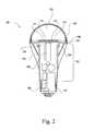
- FIG. 2is a cross-sectional view of the luminaire illustrated in FIG. 1 taken through line 2 - 2 .
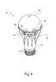
- FIG. 3is a perspective view of the luminaire illustrated in FIG. 1 .
- FIG. 4is a top perspective view of the luminaire illustrated in FIG. 1 .
- FIG. 5is a perspective view of a luminaire according to another embodiment of the present invention.
- FIG. 6is a cross-sectional view of the luminaire illustrated in FIG. 5 taken through line 6 - 6 .
- the luminaire 100may have an electrical base 110 , an optic 120 , and an intermediate member 130 between the electrical base 110 and the optic 120 .
- the optic 120may be configured, shaped, and dimensioned so as to define an optical chamber 122 .
- the intermediate member 130may include structural supports 140 as illustrated, which may be configured to engage with and carry the optic 120 .
- the intermediate member 130may also include a main body 131 and the plurality of structural supports 140 that may be connected to the main body 131 and may be configured to carry an upper member 132 .
- the upper member 132may be configured to carry the optic 120 .
- the optic 120may be carried by the intermediate member 130 , the main body 131 , the upper member 132 , or the structural supports 140 through the use of an adhesive, a glue, a slot and tab system, or any other attachment method known in the art. More specifically, for example and as illustrated in FIGS. 2-6 , the upper member 132 may include a plurality of slots 191 and the optic 120 may include a plurality of tabs 190 that fit into the plurality of slots 191 to fasten the optic 120 in place, thereby inhibiting the optic 120 from rotating or from separating vertically from the upper member 132 .
- the optic 120may be carried by the intermediate member 130 , the upper member 132 , or the structural supports 140 through the use of an adhesive, a glue, a slot and tab system, welding, ultrasonic welding, or any other attachment method known in the art.
- an adhesivea glue, a slot and tab system, welding, ultrasonic welding, or any other attachment method known in the art.
- additional devices and methods for fastening the optic 120 to the upper member 132that may be used.
- the intermediate member 130may include a heat sink 142 .
- the heat sink 142may be carried by or adjacent to the intermediate member 130 and the heat sink 142 may facilitate passive cooling of the luminaire 100 .
- the heat sink 142may be positioned adjacent the intermediate member 130 or, in some embodiments, be included in the intermediate member 130 .
- a plurality of voids 180may exist within the intermediate member 130 and may be defined by the space between the structural supports 140 themselves, and between structural supports 140 and the heat sink 142 . Additionally, each of the plurality of voids 180 may be defined by a pair of the structural supports 140 positioned adjacent to one another, the upper member 132 , and the outer surface of the main body 131 .
- the plurality of voids 180may be configured to position the optical chamber 122 and/or the heat sink 142 in fluid communication with the environment surrounding the luminaire 100 .
- the heat sink 142may be integrally molded with the intermediate member 130 , or may be of separate construction. In a case where the heat sink 142 is a separate construction from the intermediate member 130 , those skilled in the art will appreciate that the heat sink 142 may be adapted to engage a portion of the intermediate member 130 . In other words, it is contemplated by the present invention that the heat sink 142 may be a removable heat sink that may be engaged and disengaged from the intermediate member 130 .
- the luminaire 100may include one or more light source 170 .
- the light source 170may be disposed within the optical chamber 122 defined by the optic 120 and be in electrical communication with the electrical base 110 .
- the luminaire 100may further include a light source board 150 and a controller 160 , wherein the controller 160 may be configured to selectively operate the light source 170 , and wherein the light source board 150 is configured to enable the operation of the light source 170 by the controller 160 .
- the light source board 150 and controller 160may be housed in and/or carried by the intermediate member 130 , and in electrical communication with the electrical base 110 and/or the light source 170 .
- This configurationmay be particularly advantageous, as the light source 170 , the light source board 150 , and the controller 160 may benefit from the cooling effects of the heat sink 142 as shown in FIG. 2 .
- Other configurationsmay readily present themselves to such skilled artisans having had the benefit of this disclosure, and are intended to be included within the scope and spirit of the present invention.
- the luminaire 100may further include a power supply unit 162 positioned in electrical communication with the electrical base 110 , the light source board 150 , the controller 160 , and the light source 170 .
- the power supply unit 162may include circuitry and electrical components so as to receive voltage from an external power source via the electrical base 110 and transform, condition, modulate, and otherwise alter the voltage received via the electrical base 110 into one or more voltages necessary for the operation of the various electrical elements of the luminaire 100 , including, without limitation, the light source board 150 , controller 160 , and light source 170 .
- Heat sinksfunction by allowing heat from a heat source to be dissipated over a larger surface area. For this reason, ideal heat sinks may be made of materials having high heat conductivity. High heat conductivity may allow the heat sink 142 to readily accept heat from a heat source, cooling the heat source faster than the surface area of the heat source alone. Accordingly, this embodiment of the luminaire 100 advantageously utilizes the heat sink 142 to dissipate heat generated by various elements of the luminaire 100 , such as the light source 170 , light source board 150 , controller 160 , and power supply unit 162 .
- the light source board 150 and the controller 160may be in electrical communication with the electrical base 110 , and may be housed within the intermediate member 130 .
- the light source 170may be disposed within the optical chamber 122 defined by the optic 120 adjacent to the intermediate member 130 , and may be in electrical communication with the power supply unit 162 .
- the light source 170is illustrated as a plurality of lighting devices in an array, the light source 170 may be a single lighting device, or a plurality of lighting devices in any number of configurations, as will be discussed below.
- any light source 170may benefit from the circulation provided by the heat sink 142 and, more specifically, provided by the venting capabilities of the luminaire according to the present invention.
- These potential light sources 170include, but are not necessarily limited to, incandescent light bulbs, CFL bulbs, semiconductor lighting devices, LEDs, infrared lighting devices, or laser-driven lighting sources. Additionally, more than one type of lighting device may be used to provide the light source 170 .
- a conversion coatingmay be applied to the light source 170 or optic 120 to create a desired output color.
- the inclusion of a conversion coatingmay advantageously allow the luminaire 100 of the present invention to include high efficiency/efficacy LEDs, increasing the overall efficiency/efficacy of the luminaire 100 according to an embodiment of the present invention.
- conversion coatingsmay be applied, such as a conversion phosphor, delay phosphor, or quantum dot, to condition or increase the light outputted by the light source 170 .
- the optic 120may include a conversion material, a refractive material, a reflective material, a silvered surface, a tinted surface, and/or a mirrored surface.
- the light source 170may also include a conversion material, a refractive material, and/or a tinted surface. Additional details of such conversion coatings are found in U.S. patent application Ser. No. 13/357,283, titled Dual Characteristic Color Conversion Enclosure and Associated Methods, filed on Jan. 24, 2012, as well as U.S. patent application Ser. No. 13/234,371, titled Color Conversion Occlusion and Associated Methods, filed on Sep. 16, 2011, and U.S. patent application Ser. No. 13/234,604, titled Remote Light Wavelength Conversion Device and Associated Methods, the entire contents of each of which are incorporated herein by reference.
- the source wavelength range of the light generated by the light source 170may be emitted in a blue wavelength range.
- LEDs capable of emitting light in any wavelength rangesmay be used in the light source 170 , in accordance with this disclosure of the present invention.
- additional light generating devicesthat may be used in the light source 170 that may be capable of creating an illumination.
- the light source 170may generate a source light with a source wavelength range in the blue spectrum.
- the blue spectrummay include light with a wavelength range between 400 and 500 nanometers.
- a source light in the blue spectrummay be generated by a light-emitting semiconductor that is comprised of materials that may emit a light in the blue spectrum. Examples of such light emitting semiconductor materials may include, but are not intended to be limited to, zinc selenide (ZnSe) or indium gallium nitride (InGaN). These semiconductor materials may be grown or formed on substrates, which may be comprised of materials such as sapphire, silicon carbide (SiC), or silicon (Si).
- SiCsilicon carbide
- Sisilicon
- the conversion coatingmay be a phosphor substance, which may be applied to the blue LEDs.
- the phosphor substancemay absorb wavelength ranges emitted by the LEDs and emit light defined in additional wavelength ranges when energized. Energizing of the phosphor may occur upon exposure to light, such as the source light emitted from the light source 170 .
- the wavelength of light emitted by a phosphormay be dependent on the materials from which the phosphor is comprised.
- the optic 120may be coated with a refractive/reflective material.
- the reflective materialmay provide additional light in a downward direction and may only require one reflection.
- the optic 120may provide additional light in an outward direction with respect to the light source 170 and may require only one refraction.
- the emitted lightmay be increased due to the void 180 between the support structures 140 .
- a person skilled in the artwill appreciate that the use of the coating material within this disclosure is not intended to be limited to any specific type of coating. Accordingly, skilled artisans should not view the following disclosure as limited to the any particular reflective coating, and should read the following disclosure broadly with respect to the same.
- the light source 170may be mounted on the light source board 150 which may be a flat-mounted LED board and may require only one reflection/refraction.
- the light source 170may also be mounted on the light source board 150 , which may be a cylindrically-mounted LED board and may require only one reflection/refraction. This may also propagate light in all or nearly all directions including both the upper and lower hemispheres from the light source 170 .
- the light source 170may be electrically coupled to the electrical base 110 and may be positioned within the optical chamber 122 .
- the light source 170may be a plurality of light sources 170 and the light source board 150 may have a circular configuration and the plurality of light sources 170 may be distributed about the light source board 150 .
- the light source 170may be annularly distributed about the light source board 150 .
- the optic 120may be a curved surface concavely curved with respect to the light source 170 .
- the optic 120may be white or a color or the surface may be silvered, tinted, or mirrored (mirror finish).
- the optic 120may include one or more media of differing reflective and refractive indices.
- the optic 120may be, for example, one or more Fresnel lenses.
- the optic 120may reflect all light, no light, or any proportion in between.
- the optic 120may be configured to redirect at least a portion of light incident thereupon in the direction of the plurality of voids 180 .
- the optic 120may be formed of any material, for example, glass, acrylic, or plastic.
- the void 180may allow light from the light source 170 to propagate downward to the lower hemisphere in a direction toward the electrical base and outward away from the heat sink 142 and the light source 170 after being reflected/refracted by the optic 120 .
- the void 180additionally may allow air flow between at least one of the optic 120 , the structural support members 140 , the heat sink 142 , and the light source 170 .
- Air flow through the void 180may allow the heat sink 142 to cool more efficiently, for example by allowing heated air to flow faster away from at least one of the luminaire 100 in general, the heat sink 142 , the light source board 150 , the controller 160 , and the light source 170 .
- air flow through the optical chamber 122 and the dissipation of heatthereby may reduce the quantity of heat to be dissipated by the heat sink 142 , thereby permitting the heat sink 142 to be formed relatively smaller than otherwise required.
- the light source board 150may be configured to extend beyond a periphery of the intermediate member 130 and the light source board 150 may include an upper surface and a lower surface such that a region of the lower surface may extend beyond the periphery of the intermediate member 130 .
- the plurality of light sources 170may also include a first plurality of light sources 171 and a second plurality of light sources 172 and the first plurality of light sources 171 may be generally distributed about the upper surface of the light source board 150 and the second plurality of light sources 172 may be generally distributed about the lower surface of the light source board 150 .
- the controller 160may be adapted to independently operate each light source 170 of the first plurality of light sources 171 and/or the second plurality of light sources 172 .
- the light emitted by the light source 170may be within a wavelength range of at least one of about 10 nanometers to 380 nanometers, about 390 nanometers to 700 nanometers, and about 700 nanometers to 1 millimeter.
- a portion of the light emitted by the light source 170may be reflected and/or refracted by the optic in a direction substantially below a generally horizontal plane defined by the upper member 132 .
- At least a portion of the light emitted by the light source 170 that is reflected and/or refracted by the opticmay be reflected and/or refracted in the direction of the void 180 .
- the light emitted by the light source 170may include additional wavelengths and wavelength ranges.
- the luminaire 100may further include an intermediate optic 121 that may be positioned adjacent to the light source 170 and/or carried by the intermediate member 130 and the intermediate optic 121 may be configured to form a fluid seal between the light source 170 and the optical chamber 122 .
- the luminaire 100may further include a sealing member.
- the sealing membermay include any device or material that can provide a fluid seal as described above.
- the intermediate optic 121may further include a conversion material and/or a tinted surface.
- the intermediate optic 121may be carried by the intermediate member 130 through the use of an adhesive, a glue, a slot and tab system, or any other attachment method known in the art.
- a skilled artisanwill also appreciate, after having the benefit of this disclosure, additional devices and methods that may be used in attaching the intermediate optic 121 to the intermediate member 130 .
Landscapes
- Engineering & Computer Science (AREA)
- General Engineering & Computer Science (AREA)
- Physics & Mathematics (AREA)
- Microelectronics & Electronic Packaging (AREA)
- Optics & Photonics (AREA)
- Non-Portable Lighting Devices Or Systems Thereof (AREA)
- Arrangement Of Elements, Cooling, Sealing, Or The Like Of Lighting Devices (AREA)
Abstract
Description
Claims (21)
Priority Applications (1)
| Application Number | Priority Date | Filing Date | Title |
|---|---|---|---|
| US14/074,173US9322516B2 (en) | 2012-11-07 | 2013-11-07 | Luminaire having vented optical chamber and associated methods |
Applications Claiming Priority (2)
| Application Number | Priority Date | Filing Date | Title |
|---|---|---|---|
| US201261723491P | 2012-11-07 | 2012-11-07 | |
| US14/074,173US9322516B2 (en) | 2012-11-07 | 2013-11-07 | Luminaire having vented optical chamber and associated methods |
Publications (2)
| Publication Number | Publication Date |
|---|---|
| US20140133153A1 US20140133153A1 (en) | 2014-05-15 |
| US9322516B2true US9322516B2 (en) | 2016-04-26 |
Family
ID=50681536
Family Applications (1)
| Application Number | Title | Priority Date | Filing Date |
|---|---|---|---|
| US14/074,173Expired - Fee RelatedUS9322516B2 (en) | 2012-11-07 | 2013-11-07 | Luminaire having vented optical chamber and associated methods |
Country Status (1)
| Country | Link |
|---|---|
| US (1) | US9322516B2 (en) |
Cited By (5)
| Publication number | Priority date | Publication date | Assignee | Title |
|---|---|---|---|---|
| US9788387B2 (en) | 2015-09-15 | 2017-10-10 | Biological Innovation & Optimization Systems, LLC | Systems and methods for controlling the spectral content of LED lighting devices |
| US9844116B2 (en) | 2015-09-15 | 2017-12-12 | Biological Innovation & Optimization Systems, LLC | Systems and methods for controlling the spectral content of LED lighting devices |
| US9943042B2 (en) | 2015-05-18 | 2018-04-17 | Biological Innovation & Optimization Systems, LLC | Grow light embodying power delivery and data communications features |
| US10595376B2 (en) | 2016-09-13 | 2020-03-17 | Biological Innovation & Optimization Systems, LLC | Systems and methods for controlling the spectral content of LED lighting devices |
| US10591115B2 (en) | 2016-08-18 | 2020-03-17 | c2 Semiconductor, LLC | Retrofit kit and methods for conversion of fluorescent light assemblies to LED assemblies |
Families Citing this family (6)
| Publication number | Priority date | Publication date | Assignee | Title |
|---|---|---|---|---|
| US20140307427A1 (en)* | 2013-04-11 | 2014-10-16 | Lg Innotek Co., Ltd. | Lighting device |
| US20150369457A1 (en)* | 2014-06-23 | 2015-12-24 | Epistar Corporation | Light-Emitting Device |
| US11143394B2 (en) | 2018-02-08 | 2021-10-12 | Jiaxing Super Lighting Electric Appliance Co., Ltd | LED lamp |
| WO2019154139A1 (en) | 2018-02-08 | 2019-08-15 | Jiaxing Super Lighting Electric Appliance Co., Ltd | Led lamp |
| ES2884941T3 (en)* | 2018-09-20 | 2021-12-13 | Signify Holding Bv | Lighting device |
| WO2025160255A1 (en)* | 2024-01-23 | 2025-07-31 | Sogefi Air & Cooling Usa, Inc. | Thermoplastic housing |
Citations (168)
| Publication number | Priority date | Publication date | Assignee | Title |
|---|---|---|---|---|
| US5057908A (en) | 1990-07-10 | 1991-10-15 | Iowa State University Research Foundation, Inc. | High power semiconductor device with integral heat sink |
| US5523878A (en) | 1994-06-30 | 1996-06-04 | Texas Instruments Incorporated | Self-assembled monolayer coating for micro-mechanical devices |
| US5704701A (en) | 1992-03-05 | 1998-01-06 | Rank Brimar Limited | Spatial light modulator system |
| EP0851260A2 (en) | 1996-12-16 | 1998-07-01 | Ngk Insulators, Ltd. | Display device |
| US5813753A (en) | 1997-05-27 | 1998-09-29 | Philips Electronics North America Corporation | UV/blue led-phosphor device with efficient conversion of UV/blues light to visible light |
| US5997150A (en) | 1995-10-25 | 1999-12-07 | Texas Instruments Incorporated | Multiple emitter illuminator engine |
| US6140646A (en) | 1998-12-17 | 2000-10-31 | Sarnoff Corporation | Direct view infrared MEMS structure |
| US6341876B1 (en) | 1997-02-19 | 2002-01-29 | Digital Projection Limited | Illumination system |
| US6356700B1 (en) | 1998-06-08 | 2002-03-12 | Karlheinz Strobl | Efficient light engine systems, components and methods of manufacture |
| US20030039036A1 (en) | 2001-08-27 | 2003-02-27 | Eastman Kodak Company | Laser projection display system |
| US6561656B1 (en) | 2001-09-17 | 2003-05-13 | Mitsubishi Denki Kabushiki Kaisha | Illumination optical system with reflecting light valve |
| US6707611B2 (en) | 1999-10-08 | 2004-03-16 | 3M Innovative Properties Company | Optical film with variable angle prisms |
| US20040052076A1 (en) | 1997-08-26 | 2004-03-18 | Mueller George G. | Controlled lighting methods and apparatus |
| US6733135B2 (en) | 2002-04-02 | 2004-05-11 | Samsung Electronics Co., Ltd. | Image projection apparatus |
| US6767111B1 (en) | 2003-02-26 | 2004-07-27 | Kuo-Yen Lai | Projection light source from light emitting diodes |
| US6787999B2 (en) | 2002-10-03 | 2004-09-07 | Gelcore, Llc | LED-based modular lamp |
| US6799864B2 (en) | 2001-05-26 | 2004-10-05 | Gelcore Llc | High power LED power pack for spot module illumination |
| US6817735B2 (en) | 2001-05-24 | 2004-11-16 | Matsushita Electric Industrial Co., Ltd. | Illumination light source |
| US6870523B1 (en) | 2000-06-07 | 2005-03-22 | Genoa Color Technologies | Device, system and method for electronic true color display |
| US6871982B2 (en) | 2003-01-24 | 2005-03-29 | Digital Optics International Corporation | High-density illumination system |
| US20050218780A1 (en) | 2002-09-09 | 2005-10-06 | Hsing Chen | Method for manufacturing a triple wavelengths white LED |
| US6967761B2 (en) | 2000-10-31 | 2005-11-22 | Microsoft Corporation | Microelectrical mechanical structure (MEMS) optical modulator and optical display system |
| US6974713B2 (en) | 2000-08-11 | 2005-12-13 | Reflectivity, Inc. | Micromirrors with mechanisms for enhancing coupling of the micromirrors with electrostatic fields |
| US20060002110A1 (en) | 2004-03-15 | 2006-01-05 | Color Kinetics Incorporated | Methods and systems for providing lighting systems |
| US20060002108A1 (en) | 2004-06-30 | 2006-01-05 | Ouderkirk Andrew J | Phosphor based illumination system having a short pass reflector and method of making same |
| US7042623B1 (en) | 2004-10-19 | 2006-05-09 | Reflectivity, Inc | Light blocking layers in MEMS packages |
| US20060103777A1 (en) | 2004-11-15 | 2006-05-18 | 3M Innovative Properties Company | Optical film having a structured surface with rectangular based prisms |
| US7072096B2 (en) | 2001-12-14 | 2006-07-04 | Digital Optics International, Corporation | Uniform illumination system |
| US7070281B2 (en) | 2002-12-04 | 2006-07-04 | Nec Viewtechnology, Ltd. | Light source device and projection display |
| US7075707B1 (en) | 1998-11-25 | 2006-07-11 | Research Foundation Of The University Of Central Florida, Incorporated | Substrate design for optimized performance of up-conversion phosphors utilizing proper thermal management |
| US20060164005A1 (en) | 2005-01-25 | 2006-07-27 | Chuan-Sheng Sun | Illumination apparatus having adjustable color temperature and method for adjusting the color temperature |
| US7083304B2 (en) | 2003-08-01 | 2006-08-01 | Illumination Management Solutions, Inc. | Apparatus and method of using light sources of differing wavelengths in an unitized beam |
| US20060232992A1 (en) | 2003-08-12 | 2006-10-19 | Koninklijke Philips Electronics N.V. | Circuit arrangement for ac driving of organic diodes |
| US20060285193A1 (en) | 2005-06-03 | 2006-12-21 | Fuji Photo Film Co., Ltd. | Optical modulation element array |
| US20070013871A1 (en) | 2005-07-15 | 2007-01-18 | Marshall Stephen W | Light-emitting diode (LED) illumination in display systems using spatial light modulators (SLM) |
| US7178941B2 (en) | 2003-05-05 | 2007-02-20 | Color Kinetics Incorporated | Lighting methods and systems |
| US7184201B2 (en) | 2004-11-02 | 2007-02-27 | Texas Instruments Incorporated | Digital micro-mirror device having improved contrast and method for the same |
| US7187484B2 (en) | 2002-12-30 | 2007-03-06 | Texas Instruments Incorporated | Digital micromirror device with simplified drive electronics for use as temporal light modulator |
| US7213926B2 (en) | 2004-11-12 | 2007-05-08 | Hewlett-Packard Development Company, L.P. | Image projection system and method |
| US20070159492A1 (en) | 2006-01-11 | 2007-07-12 | Wintek Corporation | Image processing method and pixel arrangement used in the same |
| US7247874B2 (en) | 2003-05-26 | 2007-07-24 | Agfa-Gevaert Healthcare Gmbh | Device for detecting information contained in a phosphor layer |
| US7246923B2 (en) | 2004-02-11 | 2007-07-24 | 3M Innovative Properties Company | Reshaping light source modules and illumination systems using the same |
| US7255469B2 (en) | 2004-06-30 | 2007-08-14 | 3M Innovative Properties Company | Phosphor based illumination system having a light guide and an interference reflector |
| US20070188847A1 (en) | 2006-02-14 | 2007-08-16 | Texas Instruments Incorporated | MEMS device and method |
| US7261453B2 (en) | 2005-01-25 | 2007-08-28 | Morejon Israel J | LED polarizing optics for color illumination system and method of using same |
| US20070241340A1 (en) | 2006-04-17 | 2007-10-18 | Pan Shaoher X | Micro-mirror based display device having an improved light source |
| US7289090B2 (en) | 2003-12-10 | 2007-10-30 | Texas Instruments Incorporated | Pulsed LED scan-ring array for boosting display system lumens |
| US7300177B2 (en) | 2004-02-11 | 2007-11-27 | 3M Innovative Properties | Illumination system having a plurality of light source modules disposed in an array with a non-radially symmetrical aperture |
| US7303291B2 (en) | 2004-03-31 | 2007-12-04 | Sanyo Electric Co., Ltd. | Illumination apparatus and video projection display system |
| US7325956B2 (en) | 2005-01-25 | 2008-02-05 | Jabil Circuit, Inc. | Light-emitting diode (LED) illumination system for a digital micro-mirror device (DMD) and method of providing same |
| US7342658B2 (en) | 2005-12-28 | 2008-03-11 | Eastman Kodak Company | Programmable spectral imaging system |
| US7344279B2 (en) | 2003-12-11 | 2008-03-18 | Philips Solid-State Lighting Solutions, Inc. | Thermal management methods and apparatus for lighting devices |
| US7349095B2 (en) | 2005-05-19 | 2008-03-25 | Casio Computer Co., Ltd. | Light source apparatus and projection apparatus |
| US7353859B2 (en) | 2004-11-24 | 2008-04-08 | General Electric Company | Heat sink with microchannel cooling for power devices |
| US7382091B2 (en) | 2005-07-27 | 2008-06-03 | Lung-Chien Chen | White light emitting diode using phosphor excitation |
| US7382632B2 (en) | 2005-04-06 | 2008-06-03 | International Business Machines Corporation | Computer acoustic baffle and cable management system |
| US20080198572A1 (en) | 2007-02-21 | 2008-08-21 | Medendorp Nicholas W | LED lighting systems including luminescent layers on remote reflectors |
| US7427146B2 (en) | 2004-02-11 | 2008-09-23 | 3M Innovative Properties Company | Light-collecting illumination system |
| US20080232084A1 (en) | 2007-03-19 | 2008-09-25 | Nec Lighting, Ltd | White light source device |
| US7429983B2 (en) | 2005-11-01 | 2008-09-30 | Cheetah Omni, Llc | Packet-based digital display system |
| US7434946B2 (en) | 2005-06-17 | 2008-10-14 | Texas Instruments Incorporated | Illumination system with integrated heat dissipation device for use in display systems employing spatial light modulators |
| US7438443B2 (en) | 2003-09-19 | 2008-10-21 | Ricoh Company, Limited | Lighting device, image-reading device, color-document reading apparatus, image-forming apparatus, projection apparatus |
| US20080258643A1 (en) | 2007-04-21 | 2008-10-23 | Zippy Technology Corp. | Method for driving alternate current of light emitting diode and operating voltage thereof |
| US20080316432A1 (en) | 2007-06-25 | 2008-12-25 | Spotless, Llc | Digital Image Projection System |
| US20090009102A1 (en) | 2006-02-14 | 2009-01-08 | Koninklijke Philips Electronics N.V. | Lighting device with controllable light intensity |
| US7476016B2 (en) | 2005-06-28 | 2009-01-13 | Seiko Instruments Inc. | Illuminating device and display device including the same |
| US20090059099A1 (en) | 2007-09-05 | 2009-03-05 | Samsung Electronics Co., Ltd. | Illumination device and projection system having the same |
| US20090059585A1 (en) | 2007-08-29 | 2009-03-05 | Young Optics Inc. | Illumination system |
| US7530708B2 (en) | 2004-10-04 | 2009-05-12 | Lg Electronics Inc. | Surface emitting light source and projection display device using the same |
| US20090128781A1 (en) | 2006-06-13 | 2009-05-21 | Kenneth Li | LED multiplexer and recycler and micro-projector incorporating the Same |
| US7537347B2 (en) | 2005-11-29 | 2009-05-26 | Texas Instruments Incorporated | Method of combining dispersed light sources for projection display |
| US7540616B2 (en) | 2005-12-23 | 2009-06-02 | 3M Innovative Properties Company | Polarized, multicolor LED-based illumination source |
| US7545569B2 (en) | 2006-01-13 | 2009-06-09 | Avery Dennison Corporation | Optical apparatus with flipped compound prism structures |
| USD593963S1 (en) | 2008-04-23 | 2009-06-09 | 4187318 Canada Inc. | Modular heat sink |
| US7556406B2 (en) | 2003-03-31 | 2009-07-07 | Lumination Llc | Led light with active cooling |
| US20090232683A1 (en) | 2006-12-09 | 2009-09-17 | Murata Manufacturing Co., Ltd. | Piezoelectric micro-blower |
| US7598686B2 (en) | 1997-12-17 | 2009-10-06 | Philips Solid-State Lighting Solutions, Inc. | Organic light emitting diode methods and apparatus |
| US7605971B2 (en) | 2003-11-01 | 2009-10-20 | Silicon Quest Kabushiki-Kaisha | Plurality of hidden hinges for mircromirror device |
| US20090273931A1 (en) | 2007-01-15 | 2009-11-05 | Alps Electric Co., Ltd. | Illumination device and input unit with illumination device |
| US7626755B2 (en) | 2007-01-31 | 2009-12-01 | Panasonic Corporation | Wavelength converter and two-dimensional image display device |
| US20100006762A1 (en) | 2007-03-27 | 2010-01-14 | Kabushiki Kaisha Toshiba | Scintillator panel and radiation detector |
| US20100039704A1 (en) | 2006-10-27 | 2010-02-18 | Hideki Hayashi | Prism sheet and optical sheet |
| US20100051976A1 (en) | 2006-11-15 | 2010-03-04 | Lemnis Lighting Patent Holding B.V. | Led lighting assembly |
| US20100053959A1 (en) | 2007-04-16 | 2010-03-04 | Koninklijke Philips Electronics N.V. | Optical arrangement |
| US7677736B2 (en) | 2004-02-27 | 2010-03-16 | Panasonic Corporation | Illumination light source and two-dimensional image display using same |
| US7684007B2 (en) | 2004-08-23 | 2010-03-23 | The Boeing Company | Adaptive and interactive scene illumination |
| US7705810B2 (en) | 2003-05-07 | 2010-04-27 | Samsung Electronics Co., Ltd. | Four-color data processing system |
| US7703943B2 (en) | 2007-05-07 | 2010-04-27 | Intematix Corporation | Color tunable light source |
| US20100103389A1 (en) | 2008-10-28 | 2010-04-29 | Mcvea Kenneth Brian | Multi-MEMS Single Package MEMS Device |
| US7709811B2 (en) | 2007-07-03 | 2010-05-04 | Conner Arlie R | Light emitting diode illumination system |
| US20100109499A1 (en)* | 2008-11-03 | 2010-05-06 | Vilgiate Anthony W | Par style lamp having solid state light source |
| US7719766B2 (en) | 2007-06-20 | 2010-05-18 | Texas Instruments Incorporated | Illumination source and method therefor |
| US7728846B2 (en) | 2003-10-21 | 2010-06-01 | Samsung Electronics Co., Ltd. | Method and apparatus for converting from source color space to RGBW target color space |
| US7732825B2 (en) | 2007-03-13 | 2010-06-08 | Seoul Opto Device Co., Ltd. | AC light emitting diode |
| US20100165632A1 (en)* | 2008-12-26 | 2010-07-01 | Everlight Electronics Co., Ltd. | Heat dissipation device and luminaire comprising the same |
| US7748870B2 (en) | 2008-06-03 | 2010-07-06 | Li-Hong Technological Co., Ltd. | LED lamp bulb structure |
| US7762315B2 (en) | 2008-02-01 | 2010-07-27 | Asia Vital Components Co., Ltd. | Sectional modular heat sink |
| US7766490B2 (en) | 2006-12-13 | 2010-08-03 | Philips Lumileds Lighting Company, Llc | Multi-color primary light generation in a projection system using LEDs |
| US20100202129A1 (en) | 2009-01-21 | 2010-08-12 | Abu-Ageel Nayef M | Illumination system utilizing wavelength conversion materials and light recycling |
| US20100244700A1 (en) | 2007-12-24 | 2010-09-30 | Patrick Chong | System for Representing Colors Including an Integrating Light Capsule |
| US20100259934A1 (en)* | 2009-04-13 | 2010-10-14 | Fu Zhun Precision Industry (Shen Zhen) Co., Ltd. | Led illumination device |
| US7819556B2 (en) | 2006-12-22 | 2010-10-26 | Nuventix, Inc. | Thermal management system for LED array |
| US20100270942A1 (en) | 2009-04-24 | 2010-10-28 | City University Of Hong Kong | Apparatus and methods of operation of passive led lighting equipment |
| US7824075B2 (en) | 2006-06-08 | 2010-11-02 | Lighting Science Group Corporation | Method and apparatus for cooling a lightbulb |
| US20100277084A1 (en) | 2005-06-28 | 2010-11-04 | Seoul Opto Device Co., Ltd. | Light emitting device for ac power operation |
| US20100277067A1 (en)* | 2009-04-30 | 2010-11-04 | Lighting Science Group Corporation | Dimmable led luminaire |
| US7828453B2 (en) | 2009-03-10 | 2010-11-09 | Nepes Led Corporation | Light emitting device and lamp-cover structure containing luminescent material |
| US7828465B2 (en) | 2007-05-04 | 2010-11-09 | Koninlijke Philips Electronis N.V. | LED-based fixtures and related methods for thermal management |
| US7834867B2 (en) | 2006-04-11 | 2010-11-16 | Microvision, Inc. | Integrated photonics module and devices using integrated photonics modules |
| US7835056B2 (en) | 2005-05-13 | 2010-11-16 | Her Majesty the Queen in Right of Canada, as represented by Institut National d'Optique | Image projector with flexible reflective analog modulator |
| US7832878B2 (en) | 2006-03-06 | 2010-11-16 | Innovations In Optics, Inc. | Light emitting diode projection system |
| US7841714B2 (en) | 2008-02-07 | 2010-11-30 | Quantum Modulation Scientific Inc. | Retinal melatonin suppressor |
| US20100315320A1 (en) | 2007-12-07 | 2010-12-16 | Sony Corporation | Light source device and display device |
| US20100320927A1 (en) | 2009-06-22 | 2010-12-23 | Richard Landry Gray | Power Reforming Methods and Associated Multiphase Lights |
| US20100321641A1 (en) | 2008-02-08 | 2010-12-23 | Koninklijke Philips Electronics N.V. | Light module device |
| US7871839B2 (en) | 2004-06-30 | 2011-01-18 | Seoul Opto Device Co., Ltd. | Light emitting element with a plurality of cells bonded, method of manufacturing the same, and light emitting device using the same |
| US20110012137A1 (en) | 2004-08-31 | 2011-01-20 | Industrial Technology Research Institute | Structure of ac light-emitting diode dies |
| US7880400B2 (en) | 2007-09-21 | 2011-02-01 | Exclara, Inc. | Digital driver apparatus, method and system for solid state lighting |
| US7889430B2 (en) | 2006-05-09 | 2011-02-15 | Ostendo Technologies, Inc. | LED-based high efficiency illumination systems for use in projection systems |
| US7906789B2 (en) | 2008-07-29 | 2011-03-15 | Seoul Semiconductor Co., Ltd. | Warm white light emitting apparatus and back light module comprising the same |
| US7906722B2 (en) | 2005-04-19 | 2011-03-15 | Palo Alto Research Center Incorporated | Concentrating solar collector with solid optical element |
| US20110080635A1 (en) | 2008-06-13 | 2011-04-07 | Katsuyuki Takeuchi | Image display device and image display method |
| US7922356B2 (en) | 2008-07-31 | 2011-04-12 | Lighting Science Group Corporation | Illumination apparatus for conducting and dissipating heat from a light source |
| US7923748B2 (en) | 2003-08-21 | 2011-04-12 | Excelitas Technologies LED Solutions, Inc. | Integrated LED heat sink |
| US7928565B2 (en) | 2004-06-15 | 2011-04-19 | International Business Machines Corporation | Semiconductor device with a high thermal dissipation efficiency |
| US7972030B2 (en) | 2007-03-05 | 2011-07-05 | Intematix Corporation | Light emitting diode (LED) based lighting systems |
| US7976205B2 (en) | 2005-08-31 | 2011-07-12 | Osram Opto Semiconductors Gmbh | Light-emitting module, particularly for use in an optical projection apparatus |
| US8016443B2 (en) | 2008-05-02 | 2011-09-13 | Light Prescriptions Innovators, Llc | Remote-phosphor LED downlight |
| US8021019B2 (en) | 2008-10-15 | 2011-09-20 | Power Data Communications Co., Ltd. | Light-emitting diode lighting device with multiple-layered source |
| US8040070B2 (en) | 2008-01-23 | 2011-10-18 | Cree, Inc. | Frequency converted dimming signal generation |
| US8049763B2 (en) | 2007-08-13 | 2011-11-01 | Samsung Electronics Co., Ltd. | RGB to RGBW color decomposition method and system |
| US8047660B2 (en) | 2005-09-13 | 2011-11-01 | Texas Instruments Incorporated | Projection system and method including spatial light modulator and compact diffractive optics |
| US8061857B2 (en) | 2008-11-21 | 2011-11-22 | Hong Kong Applied Science And Technology Research Institute Co. Ltd. | LED light shaping device and illumination system |
| US8070302B2 (en) | 2005-05-10 | 2011-12-06 | Iwasaki Electric Co., Ltd. | Laminate type light-emitting diode device, and reflection type light-emitting diode unit |
| US8076680B2 (en) | 2005-03-11 | 2011-12-13 | Seoul Semiconductor Co., Ltd. | LED package having an array of light emitting cells coupled in series |
| US8083364B2 (en) | 2008-12-29 | 2011-12-27 | Osram Sylvania Inc. | Remote phosphor LED illumination system |
| US8096668B2 (en) | 2008-01-16 | 2012-01-17 | Abu-Ageel Nayef M | Illumination systems utilizing wavelength conversion materials |
| EP2410240A1 (en) | 2009-03-17 | 2012-01-25 | Fediel System, S. L. | Optical device for an led light bulb |
| US8125776B2 (en) | 2010-02-23 | 2012-02-28 | Journée Lighting, Inc. | Socket and heat sink unit for use with removable LED light module |
| US20120201034A1 (en) | 2009-09-25 | 2012-08-09 | Chia-Mao Li | Wide-Range Reflective Structure |
| US20120217861A1 (en) | 2011-02-24 | 2012-08-30 | Soni Vimal J | LED Heat Sink Assembly |
| US20120218774A1 (en) | 2011-02-28 | 2012-08-30 | Livingston Troy W | Led light bulb |
| US8274089B2 (en) | 2006-09-30 | 2012-09-25 | Seoul Opto Device Co., Ltd. | Light emitting diode having light emitting cell with different size and light emitting device thereof |
| WO2012135173A1 (en) | 2011-03-28 | 2012-10-04 | Lighting Science Group Corporation | Mems wavelength converting lighting device and associated methods |
| US20120268894A1 (en) | 2011-04-25 | 2012-10-25 | Journee Lighting, Inc. | Socket and heat sink unit for use with removable led light module |
| US8297783B2 (en) | 2008-09-10 | 2012-10-30 | Samsung Electronics Co., Ltd. | Light emitting device and system providing white light with various color temperatures |
| US8310171B2 (en) | 2009-03-13 | 2012-11-13 | Led Specialists Inc. | Line voltage dimmable constant current LED driver |
| US8319445B2 (en) | 2008-04-15 | 2012-11-27 | Boca Flasher, Inc. | Modified dimming LED driver |
| US8324840B2 (en) | 2009-06-04 | 2012-12-04 | Point Somee Limited Liability Company | Apparatus, method and system for providing AC line power to lighting devices |
| US8324823B2 (en) | 2008-09-05 | 2012-12-04 | Seoul Semiconductor Co., Ltd. | AC LED dimmer and dimming method thereby |
| US8322889B2 (en) | 2006-09-12 | 2012-12-04 | GE Lighting Solutions, LLC | Piezofan and heat sink system for enhanced heat transfer |
| US8331099B2 (en) | 2006-06-16 | 2012-12-11 | Robert Bosch Gmbh | Method for fixing an electrical or an electronic component, particularly a printed-circuit board, in a housing and fixing element therefor |
| US8337029B2 (en) | 2008-01-17 | 2012-12-25 | Intematix Corporation | Light emitting device with phosphor wavelength conversion |
| US8410717B2 (en) | 2009-06-04 | 2013-04-02 | Point Somee Limited Liability Company | Apparatus, method and system for providing AC line power to lighting devices |
| US8410725B2 (en) | 2007-06-05 | 2013-04-02 | Koninklijke Philips Electronics N.V. | Lighting system for horticultural applications |
| US8427590B2 (en) | 2009-05-29 | 2013-04-23 | Soraa, Inc. | Laser based display method and system |
| US8441210B2 (en) | 2006-01-20 | 2013-05-14 | Point Somee Limited Liability Company | Adaptive current regulation for solid state lighting |
| US8465167B2 (en) | 2011-09-16 | 2013-06-18 | Lighting Science Group Corporation | Color conversion occlusion and associated methods |
| US8531126B2 (en) | 2008-02-13 | 2013-09-10 | Canon Components, Inc. | White light emitting apparatus and line illuminator using the same in image reading apparatus |
| US8545034B2 (en) | 2012-01-24 | 2013-10-01 | Lighting Science Group Corporation | Dual characteristic color conversion enclosure and associated methods |
| US20130294087A1 (en) | 2012-05-03 | 2013-11-07 | Lighting Science Group Corporation | Luminaire with prismatic optic |
| US20130294071A1 (en) | 2012-05-03 | 2013-11-07 | Lighting Science Group Corporation | Luminaire with prismatic optic |
| US20130296976A1 (en) | 2012-05-07 | 2013-11-07 | Lighting Science Group Corporation | Dynamic wavelength adapting device to affect physiological response and associated methods |
| US20130301238A1 (en) | 2012-05-03 | 2013-11-14 | Lighting Science Group Corporation | Luminaire having a vented enclosure |
| US8598799B2 (en) | 2007-12-19 | 2013-12-03 | Epistar Corporation | Alternating current light emitting device |
| US8608341B2 (en) | 2011-03-07 | 2013-12-17 | Lighting Science Group Corporation | LED luminaire |
| US8616736B2 (en) | 2008-08-26 | 2013-12-31 | Dingguo Pan | Circular light-reflecting plate with triangular oriented prisms having identical cross section and circular plate lamp made therefrom |
| US8662672B2 (en) | 2007-10-08 | 2014-03-04 | Koninklijke Philips N.V. | Lighting device, array of lighting devices and optical projection device |
- 2013
- 2013-11-07USUS14/074,173patent/US9322516B2/ennot_activeExpired - Fee Related
Patent Citations (176)
| Publication number | Priority date | Publication date | Assignee | Title |
|---|---|---|---|---|
| US5057908A (en) | 1990-07-10 | 1991-10-15 | Iowa State University Research Foundation, Inc. | High power semiconductor device with integral heat sink |
| US5704701A (en) | 1992-03-05 | 1998-01-06 | Rank Brimar Limited | Spatial light modulator system |
| US5523878A (en) | 1994-06-30 | 1996-06-04 | Texas Instruments Incorporated | Self-assembled monolayer coating for micro-mechanical devices |
| US5997150A (en) | 1995-10-25 | 1999-12-07 | Texas Instruments Incorporated | Multiple emitter illuminator engine |
| EP0851260A2 (en) | 1996-12-16 | 1998-07-01 | Ngk Insulators, Ltd. | Display device |
| US6341876B1 (en) | 1997-02-19 | 2002-01-29 | Digital Projection Limited | Illumination system |
| US5813753A (en) | 1997-05-27 | 1998-09-29 | Philips Electronics North America Corporation | UV/blue led-phosphor device with efficient conversion of UV/blues light to visible light |
| US20040052076A1 (en) | 1997-08-26 | 2004-03-18 | Mueller George G. | Controlled lighting methods and apparatus |
| US7845823B2 (en) | 1997-08-26 | 2010-12-07 | Philips Solid-State Lighting Solutions, Inc. | Controlled lighting methods and apparatus |
| US7598686B2 (en) | 1997-12-17 | 2009-10-06 | Philips Solid-State Lighting Solutions, Inc. | Organic light emitting diode methods and apparatus |
| US6356700B1 (en) | 1998-06-08 | 2002-03-12 | Karlheinz Strobl | Efficient light engine systems, components and methods of manufacture |
| US7075707B1 (en) | 1998-11-25 | 2006-07-11 | Research Foundation Of The University Of Central Florida, Incorporated | Substrate design for optimized performance of up-conversion phosphors utilizing proper thermal management |
| US6140646A (en) | 1998-12-17 | 2000-10-31 | Sarnoff Corporation | Direct view infrared MEMS structure |
| US6707611B2 (en) | 1999-10-08 | 2004-03-16 | 3M Innovative Properties Company | Optical film with variable angle prisms |
| US6870523B1 (en) | 2000-06-07 | 2005-03-22 | Genoa Color Technologies | Device, system and method for electronic true color display |
| US6974713B2 (en) | 2000-08-11 | 2005-12-13 | Reflectivity, Inc. | Micromirrors with mechanisms for enhancing coupling of the micromirrors with electrostatic fields |
| US6967761B2 (en) | 2000-10-31 | 2005-11-22 | Microsoft Corporation | Microelectrical mechanical structure (MEMS) optical modulator and optical display system |
| US6817735B2 (en) | 2001-05-24 | 2004-11-16 | Matsushita Electric Industrial Co., Ltd. | Illumination light source |
| US6799864B2 (en) | 2001-05-26 | 2004-10-05 | Gelcore Llc | High power LED power pack for spot module illumination |
| US6594090B2 (en) | 2001-08-27 | 2003-07-15 | Eastman Kodak Company | Laser projection display system |
| US20030039036A1 (en) | 2001-08-27 | 2003-02-27 | Eastman Kodak Company | Laser projection display system |
| US6561656B1 (en) | 2001-09-17 | 2003-05-13 | Mitsubishi Denki Kabushiki Kaisha | Illumination optical system with reflecting light valve |
| US7400439B2 (en) | 2001-12-14 | 2008-07-15 | Digital Optics International Corporation | Uniform illumination system |
| US7072096B2 (en) | 2001-12-14 | 2006-07-04 | Digital Optics International, Corporation | Uniform illumination system |
| US6733135B2 (en) | 2002-04-02 | 2004-05-11 | Samsung Electronics Co., Ltd. | Image projection apparatus |
| US20050218780A1 (en) | 2002-09-09 | 2005-10-06 | Hsing Chen | Method for manufacturing a triple wavelengths white LED |
| US6787999B2 (en) | 2002-10-03 | 2004-09-07 | Gelcore, Llc | LED-based modular lamp |
| US7070281B2 (en) | 2002-12-04 | 2006-07-04 | Nec Viewtechnology, Ltd. | Light source device and projection display |
| US7187484B2 (en) | 2002-12-30 | 2007-03-06 | Texas Instruments Incorporated | Digital micromirror device with simplified drive electronics for use as temporal light modulator |
| US7520642B2 (en) | 2003-01-24 | 2009-04-21 | Digital Optics International Corporation | High-density illumination system |
| US6871982B2 (en) | 2003-01-24 | 2005-03-29 | Digital Optics International Corporation | High-density illumination system |
| US6767111B1 (en) | 2003-02-26 | 2004-07-27 | Kuo-Yen Lai | Projection light source from light emitting diodes |
| US7556406B2 (en) | 2003-03-31 | 2009-07-07 | Lumination Llc | Led light with active cooling |
| US7178941B2 (en) | 2003-05-05 | 2007-02-20 | Color Kinetics Incorporated | Lighting methods and systems |
| US7705810B2 (en) | 2003-05-07 | 2010-04-27 | Samsung Electronics Co., Ltd. | Four-color data processing system |
| US7247874B2 (en) | 2003-05-26 | 2007-07-24 | Agfa-Gevaert Healthcare Gmbh | Device for detecting information contained in a phosphor layer |
| US7083304B2 (en) | 2003-08-01 | 2006-08-01 | Illumination Management Solutions, Inc. | Apparatus and method of using light sources of differing wavelengths in an unitized beam |
| US20060232992A1 (en) | 2003-08-12 | 2006-10-19 | Koninklijke Philips Electronics N.V. | Circuit arrangement for ac driving of organic diodes |
| US7923748B2 (en) | 2003-08-21 | 2011-04-12 | Excelitas Technologies LED Solutions, Inc. | Integrated LED heat sink |
| US7438443B2 (en) | 2003-09-19 | 2008-10-21 | Ricoh Company, Limited | Lighting device, image-reading device, color-document reading apparatus, image-forming apparatus, projection apparatus |
| US7728846B2 (en) | 2003-10-21 | 2010-06-01 | Samsung Electronics Co., Ltd. | Method and apparatus for converting from source color space to RGBW target color space |
| US7605971B2 (en) | 2003-11-01 | 2009-10-20 | Silicon Quest Kabushiki-Kaisha | Plurality of hidden hinges for mircromirror device |
| US7289090B2 (en) | 2003-12-10 | 2007-10-30 | Texas Instruments Incorporated | Pulsed LED scan-ring array for boosting display system lumens |
| US7344279B2 (en) | 2003-12-11 | 2008-03-18 | Philips Solid-State Lighting Solutions, Inc. | Thermal management methods and apparatus for lighting devices |
| US7246923B2 (en) | 2004-02-11 | 2007-07-24 | 3M Innovative Properties Company | Reshaping light source modules and illumination systems using the same |
| US7300177B2 (en) | 2004-02-11 | 2007-11-27 | 3M Innovative Properties | Illumination system having a plurality of light source modules disposed in an array with a non-radially symmetrical aperture |
| US7427146B2 (en) | 2004-02-11 | 2008-09-23 | 3M Innovative Properties Company | Light-collecting illumination system |
| US7677736B2 (en) | 2004-02-27 | 2010-03-16 | Panasonic Corporation | Illumination light source and two-dimensional image display using same |
| US20060002110A1 (en) | 2004-03-15 | 2006-01-05 | Color Kinetics Incorporated | Methods and systems for providing lighting systems |
| US7303291B2 (en) | 2004-03-31 | 2007-12-04 | Sanyo Electric Co., Ltd. | Illumination apparatus and video projection display system |
| US7928565B2 (en) | 2004-06-15 | 2011-04-19 | International Business Machines Corporation | Semiconductor device with a high thermal dissipation efficiency |
| US7255469B2 (en) | 2004-06-30 | 2007-08-14 | 3M Innovative Properties Company | Phosphor based illumination system having a light guide and an interference reflector |
| US20060002108A1 (en) | 2004-06-30 | 2006-01-05 | Ouderkirk Andrew J | Phosphor based illumination system having a short pass reflector and method of making same |
| US7871839B2 (en) | 2004-06-30 | 2011-01-18 | Seoul Opto Device Co., Ltd. | Light emitting element with a plurality of cells bonded, method of manufacturing the same, and light emitting device using the same |
| US7684007B2 (en) | 2004-08-23 | 2010-03-23 | The Boeing Company | Adaptive and interactive scene illumination |
| US20110012137A1 (en) | 2004-08-31 | 2011-01-20 | Industrial Technology Research Institute | Structure of ac light-emitting diode dies |
| US7530708B2 (en) | 2004-10-04 | 2009-05-12 | Lg Electronics Inc. | Surface emitting light source and projection display device using the same |
| US7042623B1 (en) | 2004-10-19 | 2006-05-09 | Reflectivity, Inc | Light blocking layers in MEMS packages |
| US7184201B2 (en) | 2004-11-02 | 2007-02-27 | Texas Instruments Incorporated | Digital micro-mirror device having improved contrast and method for the same |
| US7213926B2 (en) | 2004-11-12 | 2007-05-08 | Hewlett-Packard Development Company, L.P. | Image projection system and method |
| US20060103777A1 (en) | 2004-11-15 | 2006-05-18 | 3M Innovative Properties Company | Optical film having a structured surface with rectangular based prisms |
| US7353859B2 (en) | 2004-11-24 | 2008-04-08 | General Electric Company | Heat sink with microchannel cooling for power devices |
| US7261453B2 (en) | 2005-01-25 | 2007-08-28 | Morejon Israel J | LED polarizing optics for color illumination system and method of using same |
| US7325956B2 (en) | 2005-01-25 | 2008-02-05 | Jabil Circuit, Inc. | Light-emitting diode (LED) illumination system for a digital micro-mirror device (DMD) and method of providing same |
| US20060164005A1 (en) | 2005-01-25 | 2006-07-27 | Chuan-Sheng Sun | Illumination apparatus having adjustable color temperature and method for adjusting the color temperature |
| US8076680B2 (en) | 2005-03-11 | 2011-12-13 | Seoul Semiconductor Co., Ltd. | LED package having an array of light emitting cells coupled in series |
| US7382632B2 (en) | 2005-04-06 | 2008-06-03 | International Business Machines Corporation | Computer acoustic baffle and cable management system |
| US7906722B2 (en) | 2005-04-19 | 2011-03-15 | Palo Alto Research Center Incorporated | Concentrating solar collector with solid optical element |
| US8070302B2 (en) | 2005-05-10 | 2011-12-06 | Iwasaki Electric Co., Ltd. | Laminate type light-emitting diode device, and reflection type light-emitting diode unit |
| US7835056B2 (en) | 2005-05-13 | 2010-11-16 | Her Majesty the Queen in Right of Canada, as represented by Institut National d'Optique | Image projector with flexible reflective analog modulator |
| US7349095B2 (en) | 2005-05-19 | 2008-03-25 | Casio Computer Co., Ltd. | Light source apparatus and projection apparatus |
| US20060285193A1 (en) | 2005-06-03 | 2006-12-21 | Fuji Photo Film Co., Ltd. | Optical modulation element array |
| US7434946B2 (en) | 2005-06-17 | 2008-10-14 | Texas Instruments Incorporated | Illumination system with integrated heat dissipation device for use in display systems employing spatial light modulators |
| US8188687B2 (en) | 2005-06-28 | 2012-05-29 | Seoul Opto Device Co., Ltd. | Light emitting device for AC power operation |
| US20100277084A1 (en) | 2005-06-28 | 2010-11-04 | Seoul Opto Device Co., Ltd. | Light emitting device for ac power operation |
| US7476016B2 (en) | 2005-06-28 | 2009-01-13 | Seiko Instruments Inc. | Illuminating device and display device including the same |
| US20070013871A1 (en) | 2005-07-15 | 2007-01-18 | Marshall Stephen W | Light-emitting diode (LED) illumination in display systems using spatial light modulators (SLM) |
| US7382091B2 (en) | 2005-07-27 | 2008-06-03 | Lung-Chien Chen | White light emitting diode using phosphor excitation |
| US7976205B2 (en) | 2005-08-31 | 2011-07-12 | Osram Opto Semiconductors Gmbh | Light-emitting module, particularly for use in an optical projection apparatus |
| US8047660B2 (en) | 2005-09-13 | 2011-11-01 | Texas Instruments Incorporated | Projection system and method including spatial light modulator and compact diffractive optics |
| US7429983B2 (en) | 2005-11-01 | 2008-09-30 | Cheetah Omni, Llc | Packet-based digital display system |
| US7537347B2 (en) | 2005-11-29 | 2009-05-26 | Texas Instruments Incorporated | Method of combining dispersed light sources for projection display |
| US7540616B2 (en) | 2005-12-23 | 2009-06-02 | 3M Innovative Properties Company | Polarized, multicolor LED-based illumination source |
| US7342658B2 (en) | 2005-12-28 | 2008-03-11 | Eastman Kodak Company | Programmable spectral imaging system |
| US20070159492A1 (en) | 2006-01-11 | 2007-07-12 | Wintek Corporation | Image processing method and pixel arrangement used in the same |
| US7545569B2 (en) | 2006-01-13 | 2009-06-09 | Avery Dennison Corporation | Optical apparatus with flipped compound prism structures |
| US8441210B2 (en) | 2006-01-20 | 2013-05-14 | Point Somee Limited Liability Company | Adaptive current regulation for solid state lighting |
| US20090009102A1 (en) | 2006-02-14 | 2009-01-08 | Koninklijke Philips Electronics N.V. | Lighting device with controllable light intensity |
| US20070188847A1 (en) | 2006-02-14 | 2007-08-16 | Texas Instruments Incorporated | MEMS device and method |
| US7832878B2 (en) | 2006-03-06 | 2010-11-16 | Innovations In Optics, Inc. | Light emitting diode projection system |
| US7834867B2 (en) | 2006-04-11 | 2010-11-16 | Microvision, Inc. | Integrated photonics module and devices using integrated photonics modules |
| US20070241340A1 (en) | 2006-04-17 | 2007-10-18 | Pan Shaoher X | Micro-mirror based display device having an improved light source |
| US7889430B2 (en) | 2006-05-09 | 2011-02-15 | Ostendo Technologies, Inc. | LED-based high efficiency illumination systems for use in projection systems |
| US7824075B2 (en) | 2006-06-08 | 2010-11-02 | Lighting Science Group Corporation | Method and apparatus for cooling a lightbulb |
| US20090128781A1 (en) | 2006-06-13 | 2009-05-21 | Kenneth Li | LED multiplexer and recycler and micro-projector incorporating the Same |
| US8331099B2 (en) | 2006-06-16 | 2012-12-11 | Robert Bosch Gmbh | Method for fixing an electrical or an electronic component, particularly a printed-circuit board, in a housing and fixing element therefor |
| US8322889B2 (en) | 2006-09-12 | 2012-12-04 | GE Lighting Solutions, LLC | Piezofan and heat sink system for enhanced heat transfer |
| US8274089B2 (en) | 2006-09-30 | 2012-09-25 | Seoul Opto Device Co., Ltd. | Light emitting diode having light emitting cell with different size and light emitting device thereof |
| US20100039704A1 (en) | 2006-10-27 | 2010-02-18 | Hideki Hayashi | Prism sheet and optical sheet |
| US20100051976A1 (en) | 2006-11-15 | 2010-03-04 | Lemnis Lighting Patent Holding B.V. | Led lighting assembly |
| US20090232683A1 (en) | 2006-12-09 | 2009-09-17 | Murata Manufacturing Co., Ltd. | Piezoelectric micro-blower |
| US7766490B2 (en) | 2006-12-13 | 2010-08-03 | Philips Lumileds Lighting Company, Llc | Multi-color primary light generation in a projection system using LEDs |
| US7819556B2 (en) | 2006-12-22 | 2010-10-26 | Nuventix, Inc. | Thermal management system for LED array |
| US20090273931A1 (en) | 2007-01-15 | 2009-11-05 | Alps Electric Co., Ltd. | Illumination device and input unit with illumination device |
| US7626755B2 (en) | 2007-01-31 | 2009-12-01 | Panasonic Corporation | Wavelength converter and two-dimensional image display device |
| US20080198572A1 (en) | 2007-02-21 | 2008-08-21 | Medendorp Nicholas W | LED lighting systems including luminescent layers on remote reflectors |
| US7972030B2 (en) | 2007-03-05 | 2011-07-05 | Intematix Corporation | Light emitting diode (LED) based lighting systems |
| US7732825B2 (en) | 2007-03-13 | 2010-06-08 | Seoul Opto Device Co., Ltd. | AC light emitting diode |
| US20080232084A1 (en) | 2007-03-19 | 2008-09-25 | Nec Lighting, Ltd | White light source device |
| US20100006762A1 (en) | 2007-03-27 | 2010-01-14 | Kabushiki Kaisha Toshiba | Scintillator panel and radiation detector |
| US20100053959A1 (en) | 2007-04-16 | 2010-03-04 | Koninklijke Philips Electronics N.V. | Optical arrangement |
| US20080258643A1 (en) | 2007-04-21 | 2008-10-23 | Zippy Technology Corp. | Method for driving alternate current of light emitting diode and operating voltage thereof |
| US7828465B2 (en) | 2007-05-04 | 2010-11-09 | Koninlijke Philips Electronis N.V. | LED-based fixtures and related methods for thermal management |
| US7703943B2 (en) | 2007-05-07 | 2010-04-27 | Intematix Corporation | Color tunable light source |
| US8410725B2 (en) | 2007-06-05 | 2013-04-02 | Koninklijke Philips Electronics N.V. | Lighting system for horticultural applications |
| US7719766B2 (en) | 2007-06-20 | 2010-05-18 | Texas Instruments Incorporated | Illumination source and method therefor |
| US20080316432A1 (en) | 2007-06-25 | 2008-12-25 | Spotless, Llc | Digital Image Projection System |
| US7709811B2 (en) | 2007-07-03 | 2010-05-04 | Conner Arlie R | Light emitting diode illumination system |
| US8049763B2 (en) | 2007-08-13 | 2011-11-01 | Samsung Electronics Co., Ltd. | RGB to RGBW color decomposition method and system |
| US20090059585A1 (en) | 2007-08-29 | 2009-03-05 | Young Optics Inc. | Illumination system |
| US20090059099A1 (en) | 2007-09-05 | 2009-03-05 | Samsung Electronics Co., Ltd. | Illumination device and projection system having the same |
| US7880400B2 (en) | 2007-09-21 | 2011-02-01 | Exclara, Inc. | Digital driver apparatus, method and system for solid state lighting |
| US8662672B2 (en) | 2007-10-08 | 2014-03-04 | Koninklijke Philips N.V. | Lighting device, array of lighting devices and optical projection device |
| US20100315320A1 (en) | 2007-12-07 | 2010-12-16 | Sony Corporation | Light source device and display device |
| US8598799B2 (en) | 2007-12-19 | 2013-12-03 | Epistar Corporation | Alternating current light emitting device |
| US20100244700A1 (en) | 2007-12-24 | 2010-09-30 | Patrick Chong | System for Representing Colors Including an Integrating Light Capsule |
| US8096668B2 (en) | 2008-01-16 | 2012-01-17 | Abu-Ageel Nayef M | Illumination systems utilizing wavelength conversion materials |
| US8337029B2 (en) | 2008-01-17 | 2012-12-25 | Intematix Corporation | Light emitting device with phosphor wavelength conversion |
| US8115419B2 (en) | 2008-01-23 | 2012-02-14 | Cree, Inc. | Lighting control device for controlling dimming, lighting device including a control device, and method of controlling lighting |
| US8040070B2 (en) | 2008-01-23 | 2011-10-18 | Cree, Inc. | Frequency converted dimming signal generation |
| US7762315B2 (en) | 2008-02-01 | 2010-07-27 | Asia Vital Components Co., Ltd. | Sectional modular heat sink |
| US7841714B2 (en) | 2008-02-07 | 2010-11-30 | Quantum Modulation Scientific Inc. | Retinal melatonin suppressor |
| US20100321641A1 (en) | 2008-02-08 | 2010-12-23 | Koninklijke Philips Electronics N.V. | Light module device |
| US8531126B2 (en) | 2008-02-13 | 2013-09-10 | Canon Components, Inc. | White light emitting apparatus and line illuminator using the same in image reading apparatus |
| US8319445B2 (en) | 2008-04-15 | 2012-11-27 | Boca Flasher, Inc. | Modified dimming LED driver |
| USD593963S1 (en) | 2008-04-23 | 2009-06-09 | 4187318 Canada Inc. | Modular heat sink |
| US8016443B2 (en) | 2008-05-02 | 2011-09-13 | Light Prescriptions Innovators, Llc | Remote-phosphor LED downlight |
| US7748870B2 (en) | 2008-06-03 | 2010-07-06 | Li-Hong Technological Co., Ltd. | LED lamp bulb structure |
| US20110080635A1 (en) | 2008-06-13 | 2011-04-07 | Katsuyuki Takeuchi | Image display device and image display method |
| US7906789B2 (en) | 2008-07-29 | 2011-03-15 | Seoul Semiconductor Co., Ltd. | Warm white light emitting apparatus and back light module comprising the same |
| US7922356B2 (en) | 2008-07-31 | 2011-04-12 | Lighting Science Group Corporation | Illumination apparatus for conducting and dissipating heat from a light source |
| US8616736B2 (en) | 2008-08-26 | 2013-12-31 | Dingguo Pan | Circular light-reflecting plate with triangular oriented prisms having identical cross section and circular plate lamp made therefrom |
| US8324823B2 (en) | 2008-09-05 | 2012-12-04 | Seoul Semiconductor Co., Ltd. | AC LED dimmer and dimming method thereby |
| US8297783B2 (en) | 2008-09-10 | 2012-10-30 | Samsung Electronics Co., Ltd. | Light emitting device and system providing white light with various color temperatures |
| US8021019B2 (en) | 2008-10-15 | 2011-09-20 | Power Data Communications Co., Ltd. | Light-emitting diode lighting device with multiple-layered source |
| US20100103389A1 (en) | 2008-10-28 | 2010-04-29 | Mcvea Kenneth Brian | Multi-MEMS Single Package MEMS Device |
| US20100109499A1 (en)* | 2008-11-03 | 2010-05-06 | Vilgiate Anthony W | Par style lamp having solid state light source |
| US8061857B2 (en) | 2008-11-21 | 2011-11-22 | Hong Kong Applied Science And Technology Research Institute Co. Ltd. | LED light shaping device and illumination system |
| US20100165632A1 (en)* | 2008-12-26 | 2010-07-01 | Everlight Electronics Co., Ltd. | Heat dissipation device and luminaire comprising the same |
| US8083364B2 (en) | 2008-12-29 | 2011-12-27 | Osram Sylvania Inc. | Remote phosphor LED illumination system |
| US20100202129A1 (en) | 2009-01-21 | 2010-08-12 | Abu-Ageel Nayef M | Illumination system utilizing wavelength conversion materials and light recycling |
| US7828453B2 (en) | 2009-03-10 | 2010-11-09 | Nepes Led Corporation | Light emitting device and lamp-cover structure containing luminescent material |
| US8310171B2 (en) | 2009-03-13 | 2012-11-13 | Led Specialists Inc. | Line voltage dimmable constant current LED driver |
| EP2410240A1 (en) | 2009-03-17 | 2012-01-25 | Fediel System, S. L. | Optical device for an led light bulb |
| US20100259934A1 (en)* | 2009-04-13 | 2010-10-14 | Fu Zhun Precision Industry (Shen Zhen) Co., Ltd. | Led illumination device |
| US20100270942A1 (en) | 2009-04-24 | 2010-10-28 | City University Of Hong Kong | Apparatus and methods of operation of passive led lighting equipment |
| US20100277067A1 (en)* | 2009-04-30 | 2010-11-04 | Lighting Science Group Corporation | Dimmable led luminaire |
| US8427590B2 (en) | 2009-05-29 | 2013-04-23 | Soraa, Inc. | Laser based display method and system |
| US8410717B2 (en) | 2009-06-04 | 2013-04-02 | Point Somee Limited Liability Company | Apparatus, method and system for providing AC line power to lighting devices |
| US8324840B2 (en) | 2009-06-04 | 2012-12-04 | Point Somee Limited Liability Company | Apparatus, method and system for providing AC line power to lighting devices |
| US20100320927A1 (en) | 2009-06-22 | 2010-12-23 | Richard Landry Gray | Power Reforming Methods and Associated Multiphase Lights |
| US20120201034A1 (en) | 2009-09-25 | 2012-08-09 | Chia-Mao Li | Wide-Range Reflective Structure |
| US8125776B2 (en) | 2010-02-23 | 2012-02-28 | Journée Lighting, Inc. | Socket and heat sink unit for use with removable LED light module |
| US20120217861A1 (en) | 2011-02-24 | 2012-08-30 | Soni Vimal J | LED Heat Sink Assembly |
| US20120218774A1 (en) | 2011-02-28 | 2012-08-30 | Livingston Troy W | Led light bulb |
| US8608341B2 (en) | 2011-03-07 | 2013-12-17 | Lighting Science Group Corporation | LED luminaire |
| US20130271818A1 (en) | 2011-03-28 | 2013-10-17 | Lighting Science Group Corporation | Wavelength converting lighting device and associated methods |
| US8384984B2 (en) | 2011-03-28 | 2013-02-26 | Lighting Science Group Corporation | MEMS wavelength converting lighting device and associated methods |
| WO2012135173A1 (en) | 2011-03-28 | 2012-10-04 | Lighting Science Group Corporation | Mems wavelength converting lighting device and associated methods |
| US20120268894A1 (en) | 2011-04-25 | 2012-10-25 | Journee Lighting, Inc. | Socket and heat sink unit for use with removable led light module |
| US8465167B2 (en) | 2011-09-16 | 2013-06-18 | Lighting Science Group Corporation | Color conversion occlusion and associated methods |
| US8545034B2 (en) | 2012-01-24 | 2013-10-01 | Lighting Science Group Corporation | Dual characteristic color conversion enclosure and associated methods |
| US20130294087A1 (en) | 2012-05-03 | 2013-11-07 | Lighting Science Group Corporation | Luminaire with prismatic optic |
| US20130294071A1 (en) | 2012-05-03 | 2013-11-07 | Lighting Science Group Corporation | Luminaire with prismatic optic |
| US20130301238A1 (en) | 2012-05-03 | 2013-11-14 | Lighting Science Group Corporation | Luminaire having a vented enclosure |
| US20130296976A1 (en) | 2012-05-07 | 2013-11-07 | Lighting Science Group Corporation | Dynamic wavelength adapting device to affect physiological response and associated methods |
Non-Patent Citations (9)
| Title |
|---|
| Arthur P. Fraas, Heat Exchanger Design, 1989, p. 60, John Wiley & Sons, Inc., Canada. |
| H. A El-Shaikh, S. V. Garimella, "Enhancement of Air Jet Impingement Heat Transfer using Pin-Fin Heat Sinks", D IEEE Transactions on Components and Packaging Technology, Jun. 2000, vol. 23, No. 2. |
| J. Y. San, C. H. Huang, M. H, Shu, "Impingement cooling of a confined circular air jet", In t. J. Heat Mass Transf., 1997. pp. 1355-1364, vol. 40. |
| Jones, Eric D., Light Emitting Diodes (LEDs) for General Lumination, an Optoelectronics Industry Development Association (OIDA) Technology Roadmap, OIDA Report, Mar. 2001, published by OIDA in Washington D.C. |
| N. T. Obot, W. J. Douglas, A S. Mujumdar, "Effect of Semi-confinement on Impingement Heat Transfer", Proc. 7th Int. Heat Transf. Conf., 1982, pp. 1355-1364. vol. 3. |
| S. A Solovitz, L. D. Stevanovic, R. A Beaupre, "Microchannels Take Heatsinks to the Next Level", Power Electronics Technology, Nov. 2006. |
| Tannith Cattermole, "Smart Energy Class controls light on demand", Gizmag.com, Apr. 18, 2010 accessed Nov. 1, 2011. |
| U.S. Appl. No. 13/832,900, filed Mar. 2013, Holland et al. |
| Yongmann M. Chung, Kai H. Luo, "Unsteady Heat Transfer Analysis of an Impinging Jet", Journal of Heat Transfer-Transactions of the ASME, Dec. 2002, pp. 1039-1048, vol. 124, No. 6. |
Cited By (8)
| Publication number | Priority date | Publication date | Assignee | Title |
|---|---|---|---|---|
| US9943042B2 (en) | 2015-05-18 | 2018-04-17 | Biological Innovation & Optimization Systems, LLC | Grow light embodying power delivery and data communications features |
| US10517231B2 (en) | 2015-05-18 | 2019-12-31 | Biological Innovation And Optimization Systems, Llc | Vegetation grow light embodying power delivery and data communication features |
| US9788387B2 (en) | 2015-09-15 | 2017-10-10 | Biological Innovation & Optimization Systems, LLC | Systems and methods for controlling the spectral content of LED lighting devices |
| US9844116B2 (en) | 2015-09-15 | 2017-12-12 | Biological Innovation & Optimization Systems, LLC | Systems and methods for controlling the spectral content of LED lighting devices |
| US10591115B2 (en) | 2016-08-18 | 2020-03-17 | c2 Semiconductor, LLC | Retrofit kit and methods for conversion of fluorescent light assemblies to LED assemblies |
| US10595376B2 (en) | 2016-09-13 | 2020-03-17 | Biological Innovation & Optimization Systems, LLC | Systems and methods for controlling the spectral content of LED lighting devices |
| US11426555B2 (en) | 2016-09-13 | 2022-08-30 | Biological Innovation And Optimization Systems, Llc | Luminaires, systems and methods for providing spectrally and spatially modulated illumination |
| US11857732B2 (en) | 2016-09-13 | 2024-01-02 | Biological Innovation And Optimization Systems, Llc | Luminaires, systems and methods for providing spectrally and spatially modulated illumination |
Also Published As
| Publication number | Publication date |
|---|---|
| US20140133153A1 (en) | 2014-05-15 |
Similar Documents
| Publication | Publication Date | Title |
|---|---|---|
| US9322516B2 (en) | Luminaire having vented optical chamber and associated methods | |
| US8038314B2 (en) | Light emitting diode troffer | |
| JP5566564B2 (en) | LED light bulb | |
| US8558438B2 (en) | Fixtures for large area directional and isotropic solid state lighting panels | |
| CN101641550B (en) | Light-emitting diode (LED)-based lighting systems | |
| US6964507B2 (en) | Sign illumination system | |
| JP5608684B2 (en) | LED based lamp and thermal management system for the lamp | |
| JP5715307B2 (en) | Light emitting device | |
| US9157618B2 (en) | Trough luminaire with magnetic lighting devices and associated systems and methods | |
| CN110274162A (en) | Luminaire with long-range dispersing element and total internal reflection extractor element | |
| CN102449386A (en) | Reflector system for lighting devices | |
| KR20120027401A (en) | Illumination device and method for assembly of an illumination device | |
| US20140362563A1 (en) | Fixtures for large area directional and isotropic solid state lighting panels | |
| EP3542400A1 (en) | Lighting device with uv led | |
| US20110062868A1 (en) | High luminous output LED lighting devices | |
| US9702512B2 (en) | Solid-state lamp with angular distribution optic | |
| US20130100677A1 (en) | Lighting structure | |
| RU2444676C1 (en) | Light-emitting diode radiation source | |
| TWI409406B (en) | Led lamp | |
| TWI573951B (en) | Led light guide lamp | |
| CN105190162A (en) | Modular Lens Troffer Luminaires | |
| CN102147060B (en) | Lamp fitting | |
| TWI398605B (en) | Led lamp | |
| TW201441540A (en) | Light emitting diode bulb | |
| KR20130139575A (en) | Optical semiconductor based illuminating apparatus |
Legal Events
| Date | Code | Title | Description |
|---|---|---|---|
| AS | Assignment | Owner name:LIGHTING SCIENCE GROUP CORPORATION, FLORIDA Free format text:ASSIGNMENT OF ASSIGNORS INTEREST;ASSIGNORS:BOOMGAARDEN, MARK PENLEY;HOLLAND, ERIC;LECLAIR, RICK;SIGNING DATES FROM 20131206 TO 20140121;REEL/FRAME:032014/0740 | |
| AS | Assignment | Owner name:FCC, LLC D/B/A FIRST CAPITAL, AS AGENT, GEORGIA Free format text:SECURITY INTEREST;ASSIGNORS:LIGHTING SCIENCE GROUP CORPORATION;BIOLOGICAL ILLUMINATION, LLC;REEL/FRAME:032765/0910 Effective date:20140425 | |
| AS | Assignment | Owner name:MEDLEY CAPTIAL CORPORATION, AS AGENT, NEW YORK Free format text:SECURITY INTEREST;ASSIGNORS:LIGHTING SCIENCE GROUP CORPORATION;BIOLOGICAL ILLUMINATION, LLC;REEL/FRAME:033072/0395 Effective date:20140219 | |
| AS | Assignment | Owner name:ACF FINCO I LP, NEW YORK Free format text:ASSIGNMENT AND ASSUMPTION OF SECURITY INTERESTS IN PATENTS;ASSIGNOR:FCC, LLC D/B/A FIRST CAPITAL;REEL/FRAME:035774/0632 Effective date:20150518 | |
| ZAAA | Notice of allowance and fees due | Free format text:ORIGINAL CODE: NOA | |
| ZAAB | Notice of allowance mailed | Free format text:ORIGINAL CODE: MN/=. | |
| STCF | Information on status: patent grant | Free format text:PATENTED CASE | |
| AS | Assignment | Owner name:ACF FINCO I LP, AS AGENT, NEW YORK Free format text:SECURITY INTEREST;ASSIGNORS:LIGHTING SCIENCE GROUP CORPORATION;BIOLOGICAL ILLUMINATION, LLC;REEL/FRAME:040555/0884 Effective date:20161031 | |
| AS | Assignment | Owner name:LIGHTING SCIENCE GROUP CORPORATION, A DELAWARE COR Free format text:RELEASE BY SECURED PARTY;ASSIGNOR:ACF FINCO I LP, A DELAWARE LIMITED PARTNERSHIP;REEL/FRAME:042340/0309 Effective date:20170425 Owner name:BIOLOGICAL ILLUMINATION, LLC, A DELAWARE LIMITED L Free format text:RELEASE BY SECURED PARTY;ASSIGNOR:ACF FINCO I LP, A DELAWARE LIMITED PARTNERSHIP;REEL/FRAME:042340/0309 Effective date:20170425 Owner name:LIGHTING SCIENCE GROUP CORPORATION, A DELAWARE COR Free format text:RELEASE BY SECURED PARTY;ASSIGNOR:ACF FINCO I LP, A DELAWARE LIMITED PARTNERSHIP;REEL/FRAME:042340/0471 Effective date:20170425 Owner name:BIOLOGICAL ILLUMINATION, LLC, A DELAWARE LIMITED L Free format text:RELEASE BY SECURED PARTY;ASSIGNOR:ACF FINCO I LP, A DELAWARE LIMITED PARTNERSHIP;REEL/FRAME:042340/0471 Effective date:20170425 | |
| AS | Assignment | Owner name:BIOLOGICAL ILLUMINATION, LLC, A DELAWARE LIMITED L Free format text:RELEASE BY SECURED PARTY;ASSIGNOR:MEDLEY CAPITAL CORPORATION;REEL/FRAME:048018/0515 Effective date:20180809 Owner name:LIGHTING SCIENCE GROUP CORPORATION, A DELAWARE COR Free format text:RELEASE BY SECURED PARTY;ASSIGNOR:MEDLEY CAPITAL CORPORATION;REEL/FRAME:048018/0515 Effective date:20180809 | |
| MAFP | Maintenance fee payment | Free format text:PAYMENT OF MAINTENANCE FEE, 4TH YR, SMALL ENTITY (ORIGINAL EVENT CODE: M2551); ENTITY STATUS OF PATENT OWNER: SMALL ENTITY Year of fee payment:4 | |
| FEPP | Fee payment procedure | Free format text:MAINTENANCE FEE REMINDER MAILED (ORIGINAL EVENT CODE: REM.); ENTITY STATUS OF PATENT OWNER: SMALL ENTITY | |
| LAPS | Lapse for failure to pay maintenance fees | Free format text:PATENT EXPIRED FOR FAILURE TO PAY MAINTENANCE FEES (ORIGINAL EVENT CODE: EXP.); ENTITY STATUS OF PATENT OWNER: SMALL ENTITY | |
| STCH | Information on status: patent discontinuation | Free format text:PATENT EXPIRED DUE TO NONPAYMENT OF MAINTENANCE FEES UNDER 37 CFR 1.362 | |
| FP | Lapsed due to failure to pay maintenance fee | Effective date:20240426 |