US9318008B2 - Signal emitting retail device - Google Patents
Signal emitting retail deviceDownload PDFInfo
- Publication number
- US9318008B2 US9318008B2US14/215,575US201414215575AUS9318008B2US 9318008 B2US9318008 B2US 9318008B2US 201414215575 AUS201414215575 AUS 201414215575AUS 9318008 B2US9318008 B2US 9318008B2
- Authority
- US
- United States
- Prior art keywords
- configuration
- merchandise
- electronic unit
- emitter
- sensor
- Prior art date
- Legal status (The legal status is an assumption and is not a legal conclusion. Google has not performed a legal analysis and makes no representation as to the accuracy of the status listed.)
- Active, expires
Links
- 230000009849deactivationEffects0.000claimsdescription6
- 230000007246mechanismEffects0.000description17
- 235000014676Phragmites communisNutrition0.000description9
- 230000003287optical effectEffects0.000description7
- 239000011295pitchSubstances0.000description6
- 238000000034methodMethods0.000description5
- 230000000284resting effectEffects0.000description5
- 238000010586diagramMethods0.000description3
- 230000006870functionEffects0.000description3
- 238000001514detection methodMethods0.000description2
- 238000009434installationMethods0.000description2
- 230000004048modificationEffects0.000description2
- 238000012986modificationMethods0.000description2
- 230000008569processEffects0.000description2
- 230000000903blocking effectEffects0.000description1
- 230000001413cellular effectEffects0.000description1
- 238000006073displacement reactionMethods0.000description1
- 230000005484gravityEffects0.000description1
- 230000001939inductive effectEffects0.000description1
- 239000000463materialSubstances0.000description1
- 239000002184metalSubstances0.000description1
- 238000004806packaging method and processMethods0.000description1
- 230000002265preventionEffects0.000description1
- 230000004044responseEffects0.000description1
- 230000007704transitionEffects0.000description1
Images


Classifications
- G—PHYSICS
- G08—SIGNALLING
- G08B—SIGNALLING OR CALLING SYSTEMS; ORDER TELEGRAPHS; ALARM SYSTEMS
- G08B13/00—Burglar, theft or intruder alarms
- G08B13/02—Mechanical actuation
- G08B13/14—Mechanical actuation by lifting or attempted removal of hand-portable articles
- G—PHYSICS
- G08—SIGNALLING
- G08B—SIGNALLING OR CALLING SYSTEMS; ORDER TELEGRAPHS; ALARM SYSTEMS
- G08B13/00—Burglar, theft or intruder alarms
- G08B13/02—Mechanical actuation
- G08B13/14—Mechanical actuation by lifting or attempted removal of hand-portable articles
- G08B13/149—Mechanical actuation by lifting or attempted removal of hand-portable articles with electric, magnetic, capacitive switch actuation
- A—HUMAN NECESSITIES
- A47—FURNITURE; DOMESTIC ARTICLES OR APPLIANCES; COFFEE MILLS; SPICE MILLS; SUCTION CLEANERS IN GENERAL
- A47F—SPECIAL FURNITURE, FITTINGS, OR ACCESSORIES FOR SHOPS, STOREHOUSES, BARS, RESTAURANTS OR THE LIKE; PAYING COUNTERS
- A47F5/00—Show stands, hangers, or shelves characterised by their constructional features
- A47F5/08—Show stands, hangers, or shelves characterised by their constructional features secured to the wall, ceiling, or the like; Wall-bracket display devices
- A47F5/0807—Display panels, grids or rods used for suspending merchandise or cards supporting articles; Movable brackets therefor
- A47F5/0815—Panel constructions with apertures for article supports, e.g. hooks
- A47F5/0823—Article supports for peg-boards
- A—HUMAN NECESSITIES
- A47—FURNITURE; DOMESTIC ARTICLES OR APPLIANCES; COFFEE MILLS; SPICE MILLS; SUCTION CLEANERS IN GENERAL
- A47F—SPECIAL FURNITURE, FITTINGS, OR ACCESSORIES FOR SHOPS, STOREHOUSES, BARS, RESTAURANTS OR THE LIKE; PAYING COUNTERS
- A47F5/00—Show stands, hangers, or shelves characterised by their constructional features
- A47F5/08—Show stands, hangers, or shelves characterised by their constructional features secured to the wall, ceiling, or the like; Wall-bracket display devices
- A47F5/0807—Display panels, grids or rods used for suspending merchandise or cards supporting articles; Movable brackets therefor
- A47F5/0861—Anti-theft means therefor
Definitions
- This inventiongenerally relates to systems used in retail, and more particularly to anti-theft systems operable to indicate when an item of merchandise has been removed from a retail display.
- Loss preventionis a continuing problem in the retail industry.
- Current anti-theft systemsinvolve locking up merchandise behind counters, far away from related merchandise, or locking up the merchandise in secure cabinets, closer to the place where related merchandise is generally stored.
- the anti-theft systemshould be able to be retrofitted onto existing retail displays to keep the cost of installation and the shelving downtime required for installation as low as possible.
- an audible alarm emitting signal retail deviceincludes a top wire supporting a label holder.
- the devicefurther includes a bottom wire spaced apart from the top wire and configured to support merchandise.
- the label holderis actuateable between a first configuration in which merchandise is prevented from being removed from the bottom wire and a second configuration in which merchandise is allowed to be removed from the bottom wire.
- the devicealso includes an electronic unit including a sensor coupled with an emitter and the timer.
- the sensoris configured to sense actuation of the label holder between the first configuration and the second configuration.
- the timeris configured to determine the amount of time that the label holder is in the second configuration.
- the emitteris configured to emit an audible alarm signal when the amount of time the label holder is in the second configuration exceeds a predetermined amount of time.
- the emitteris configured to emit a first audible signal indicative of a non-potential threat condition when the label holder is in the second configuration for a non-zero amount of time less than the predetermined amount of time.
- the predetermined amount of timeis adjustable.
- the devicefurther includes a power source.
- the sensorincludes a switch having an open configuration and a closed configuration, a first contact electrically connected to a power supply, and a second contact electrically connected to the emitter, such that when the switch is in the open configuration, the power supply does not supply power to the emitter, and when the switch is in the closed configuration the power supply supplies power to the emitter.
- the switchis in the open configuration when the label holder is in the first configuration.
- the switchis in the closed configuration when the label holder is in the second configuration.
- the deviceincludes a magnet coupled with the label holder.
- the sensorincludes a reed switch. Actuation of the label holder actuates the reed switch between its open and closed configurations.
- a signal emitting retail deviceincludes a first merchandise support portion and a second portion actuateable between a first configuration in which merchandise is prevented from being removed from the merchandise support portion and a second configuration in which merchandise is allowed to be removed from the merchandise support portion.
- the deviceincludes an electronic unit including a sensor coupled with an emitter. A sensor is configured to sense when the second portion is actuated from the first configuration to the second configuration. The emitter is configured to emit a signal based on the sensor sensing that the second portion has been actuated from the first configuration to the second configuration.
- the first merchandise support portionincludes a bottom wire configured to support merchandise.
- the signal emitting retail devicealso includes a top wire configured to support the second portion.
- the top wireextends generally parallel with the bottom wire.
- the second portionincludes a locking mechanism biased towards the second configuration. Actuation of the locking mechanism activates the electronic unit.
- the bottom wireis configured to support a lock arranged to maintain the locking mechanism in the first configuration when the electronic unit is to be maintained in a deactivated configuration.
- the deviceincludes a timer. The timer begins measuring time on actuation of the second portion of the first configuration to the second configuration. If the amount of time measured by the timer exceeds a predetermined amount of time, the emitter is configured to emit a signal indicative of a potential theft condition.
- the second portionmay lock in the first configuration upon sensing of a potential theft condition.
- the emitteris configured to emit a first audible signal when the sensor senses that the second portion has been actuated between the first configuration and the second configuration.
- the emitteris configured to emit a second audible signal when the amount of time exceeds the predetermined amount of time.
- the first audible signal and the second audible signalare each of at least one of different frequencies, wavelengths, pitches, frequencies of occurrence and volumes.
- the emitteris configured to emit at least one of audible sound waves, infrared, visible light, radio waves, and microwaves.
- the unitincludes an emitter coupled with a sensor.
- the electronic unitis configured to couple with a device for displaying merchandise.
- the sensoris configured to detect at least one of removal of merchandise from the device for displaying merchandise and actuation of the device for displaying merchandise.
- the emitteris configured to emit a signal upon sensing by the sensor of at least one of removal of merchandise from the device for displaying merchandise and actuation of the device for displaying merchandise.
- the senorincludes a switch having an open position and an closed position, a first contact electrically connected to a power supply, and a second contact electrically connected to the emitter.
- the switchWhen the switch is in the open position, the power supply does not supply power to the emitter.
- the switchWhen the switch is in the closed position the power supply supplies power to the emitter.
- the sensoris configured to sense a first condition wherein merchandise removal from the device for displaying merchandise indicates a non-potential theft condition.
- the sensoris also configured to sense a second condition wherein merchandise removal from the device for displaying merchandise indicates a potential theft condition.
- the emitteris configured to emit a first signal indicative of a non-potential theft condition when a non-potential theft condition is sensed by the sensor and to emit a second signal indicative of a potential theft condition when a potential theft condition is sensed by the sensor.
- the device for displaying merchandiseincludes a display hook including a device actuateable between a first configuration in which removal of merchandise from the display hook is prevented and a second configuration in which removal of merchandise from the display hook is allowed.
- the electronic unitfurther includes a timer. The timer is configured to measure time that the device is in the second configuration.
- the emitteris configured to emit a first signal indicative of a non-potential theft condition when the amount of time that the device is in the second configuration is less than a predetermined amount and to emit a second signal indicative of a potential theft condition when the amount of time the device is in the second configuration is more than a predetermined amount.
- the electronic unitdetermines the frequency with which merchandise is removed from the display hook.
- the emitteris configured to emit an audible signal. The audible signal increases in one of pitch, frequency, decibel level, or frequency of occurrence when a frequency greater than or equal to a predetermined frequency is determined.
- the predetermined amountis adjustable.
- the device for displaying merchandise with which the electronic unit is configured to couple withis one of a unit of shelving and a cabinet.
- the signalidentifies the electronic unit.
- a signal emitting retail devicein yet another aspect, includes a first merchandise support portion and a second portion actuatable between a first configuration in which merchandise is prevented from being removed from the merchandise support portion and a second configuration in which merchandise is allowed to be removed from the merchandise support portion.
- the signal emitting retail devicealso includes an electronic unit including a sensor coupled with an emitter and a timer.
- the sensoris configured to sense when the second portion is actuated from the first configuration to the second configuration.
- the emitteris configured to emit a signal based on the sensor sensing that the second portion has been actuated from the first configuration to the second configuration.
- the timeris configured to measure a time that the second portion is in the second configuration.
- the electronic unitfurther includes a mode switch for toggling the electronic unit between a first operational mode and a second operational mode.
- the emitterIn the first operational mode, the emitter emits a pre-alarm after the second portion has remained in the second configuration for equal to or greater than a predetermined first period of time. In the first operational mode, the emitter emits a final audible alarm after the second portion has remained in the second configuration for equal to or greater than a predetermined second period of time greater than the first period of time.
- the first period of timeis about three seconds, and the second period of time is about six seconds.
- the emitteremits the final audible alarm after the second portion has transitioned between the first configuration and a second configuration a predetermined number of times in a given time period.
- the predetermined number of timesmay be four times, and the given time period may be about ten seconds.
- the emitterrepeats an audible tone upon successive passages of a predetermined time interval while the second portion remains in the second configuration.
- the predetermined time intervalmay be about one second.
- an electronic unit for a signal emitting retail deviceincludes an emitter coupled with a sensor and a timer.
- the electronic unitis configured to couple with a device for displaying merchandise.
- the sensoris configured to detect at least one of removal of merchandise from the device for displaying merchandise and actuation of the device for displaying merchandise.
- the emitteris configured to emit a signal upon sensing by the sensor of at least one of removal of merchandise from the device for displaying merchandise and actuation of the device for displaying merchandise.
- the timeris configured to measure a time that the device is in the second configuration.
- the device for displaying merchandiseincludes a display hook including a device actuatable between a first configuration in which removal of merchandise from the display hook is prevented and a second configuration in which removal of merchandise from the display hook is allowed.
- the emitterincludes a mode switch of toggling the electronic unit between a first operational mode and a second operational mode. In the first operational mode, the electronic unit has at least one preset condition upon the occurrence of which will generate a final audible alarm that lasts for a predetermined time period, and wherein in the second operational mode the electronic unit will not generate a final audible alarm.
- the at least one preset conditionincludes a condition wherein the device actuatable between the first configuration and second configuration has remained in the second configuration for a predetermined period of time.
- the predetermined period of timemay be equal to or greater than about six seconds.
- the at least one preset conditionincludes a condition wherein the device actuatable between the first configuration and second configuration has transitioned between the first configuration and the second configuration a predetermined number of times in a predetermined period of time.
- the predetermined number of timesmay be four times, and wherein the predetermined period of time may be about ten seconds.
- the electronic unitmay also include an optical sensor configured to receive an optical signal, wherein upon receipt of the optical signal, the final audible alarm is deactivated.
- the predetermined time period of the final audible alarmis about 2 minutes.
- the senorcomprises a switch having an open position and a closed position, a first contact electrically connected to a power supply, and a second contact electrically connected to the emitter, such that when the switch is in the open position the power supply does not supply power to the emitter, and when the switch is in the closed position, the power supply supplies power to the emitter.
- FIG. 1is a perspective view of a signal receiver, an output receiving device, and retail display devices including embodiments of signal emitting retail devices, such as an audible alarm sounding retail devices, according to the teachings of the present invention, arranged as component in a theft deterrent system, such as an audible anti-theft system;
- signal emitting retail devicessuch as an audible alarm sounding retail devices
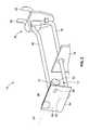
- FIG. 2is a detailed view of a signal emitting retail device of FIG. 1 ;
- FIG. 3is a side view of the signal emitting retail device of FIG. 2 illustrating actuation of a label holder and removal of merchandise;
- FIG. 4is schematic representation of components of the signal emitting retail device of FIGS. 2 and 3 ;
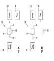
- FIG. 5Ais a schematic representation of an embodiment of a signal emitting retail device including a reed switch in an open configuration
- FIG. 5Bis a schematic representation of an embodiment of a signal emitting retail device including a reed switch in an open configuration
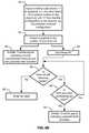
- FIG. 6Ais a flow diagram illustrating operation of an embodiment of a signal emitting retail device of FIGS. 2 and 3 ;
- FIG. 6Bis a flow diagram illustrating operation of an embodiment of a signal emitting retail device of FIGS. 2 and 3 ;
- FIG. 7is a perspective view of another embodiment of a signal emitting retail device.
- FIG. 8is a perspective view of another embodiment of a signal emitting retail device
- FIG. 9is a perspective view of another embodiment of a signal emitting retail device.
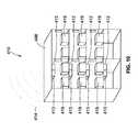
- FIG. 10is another embodiment of a retail display device of FIG. 1 ;
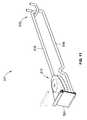
- FIG. 11is a perspective view of another embodiment of a signal emitting retail device.
- FIG. 12is a bottom view of the embodiment of FIG. 11 .
- embodiments of the present inventionprovide a signal emitting retail device that, when used in various arrangements of an audible anti-theft system, will deter theft without discouraging the sale of merchandise.
- FIG. 1depicts various embodiments of retail display devices 10 , such as, in one embodiment, retail display devices configured to emit alarm signals, such as audible alarm signals, in a first arrangement of an embodiment of a theft deterrent system, such as, in one embodiment, an audible anti-theft alarm system.
- the theft deterrent systemfurther includes an embodiment of a signal receiver unit 50 , such as, in one embodiment, an audible alarm receiver unit and an output receiving device 60 , such as, in one embodiment, a computer.
- the retail display devices 10include signal emitting retail devices 11 adapted to emit a signal 14 when merchandise is removed from the retail display devices or when the retail display devices are actuated to allow for merchandise to be removed.
- the signal emitting retail devices 11including an emitter 12 and a sensor 13 .
- the emitter 12 and sensor 13may be arranged in a single housing. In other embodiments, the emitter 12 and sensor 13 may be separate units in operative communication.
- the sensor 13is arranged and configured in some embodiments to sense when a retail display device 10 is actuated to allow for removal of merchandise, such as, for example, to sense when a door of a display case is opened or when a label holder blocking removal of merchandise in a first configuration is moved to a second configuration in which merchandise is allowed to be removed.
- a sensor 13is arranged and configured to sense when merchandise is removed from a shelf.
- Sensors 13may be motion sensors, inductive sensors, capacitive sensors, optical sensors, piezo electric sensors, or any other type of sensor known in the art for determining when merchandise is removed from a retail display device 10 or when a retail display device 10 is actuated to allow removal of merchandise. Specific embodiments of sensor arrangements will be discussed further below.
- the emitters 12 of the signal emitting retail devices 11are also adapted to transmit signals, such as, in one embodiment audible alarms, for example and as will be discussed further below, increasing in pitch, frequency, frequency of occurrence, or decibel level, when a condition is sensed by sensors 13 that would indicate a potential theft condition. Such conditions are further discussed below.
- signals 14 emitted by the signal emitting retail devices 11are received by the receiver unit 50 .
- the receiver unit 50is configured to receive and process these signals 14 .
- the signals 14may include a variety of information for the receiver unit 50 , including identification of the particular retail display unit 10 from which the signal was emitted, an identification of whether an item of merchandise has been removed, the retail display unit 10 has been actuated, or a potential theft condition exists.
- the receiver unit 50receives the signals 14 , processes and determines the information contained therein, and sends a signal 52 to an output receiving device 60 .
- the emitters 12may include a speaker or speakers and are configured to emit audible signals.
- the frequency of occurrence, decibel level, or pitch of the audible signalindicate to the receiver unit 50 the retail display unit 10 from which the audible signal was emitted, whether there is a normal condition that indicates a regular customer removal of merchandise from a retail display unit 10 or a customer actuating a retail display unit 10 to remove an item of merchandise, or whether a potential theft condition exists to which store personnel should be alerted.
- the receiver unit 50then sends a signal 52 , if appropriate, to an output receiving device 60 to alert store personnel to the potential theft condition.
- This first arrangementmay be effective in large retail environments where store personnel may be too far away to hear a particular audible signal indicating a potential theft condition.
- the output receiving device 60may be a computer, a pager, a cellular telephone, a public address system, a memory, a camera, a video camera, or any other device capable of receiving a signal 52 .
- the receiving device 60may be networked with other receiving devices located on or off site, or may be a stand alone unit located on or off site relative to a retail establishment.
- signal emitting retail devices 11deter theft and alert store personnel when a potential theft condition has occurred simply by emitting an audible alarm signal to be heard by store personnel and a potential thief.
- This embodimentmay be particularly effective in smaller retail environments where store personnel are likely to be close enough to hear the audible alarm signal.
- the audible alarm signalmay be a siren, a pre-recorded message, a buzzer, or any other suitable alarm signal.
- the signal emitting retail devices 11may be configured to emit various other types of encoded signals using any suitable protocol.
- the signals emittedmay include at least one of an audible sound, infrared light, visible light, radio waves, and microwaves.
- the signal 52 emitted by the receiver unit 50may be of any suitable type and may be an encoded signal using any suitable protocol.
- signal emitting retail devices 11can be used in many different arrangements, and the quantity and type of signal emitting retail devices 11 and other components shown are exemplary and for illustrative purposes only.
- the signal emitting retail device 11includes a display interfacing portion 15 .
- the display interface portion 15includes upturned hooks 20 adapted to fit in a pegboard style mounting surface to support the signal emitting retail device 11 .
- many other mounting arrangementsare also envisioned, including mounting arrangements adapted to be installed on slatwall and wire cage type retail display surfaces.
- the signal emitting retail device 11extending from the display interfacing portion 15 in a direction opposite the upturned hooks 20 , the signal emitting retail device 11 includes a top wire 16 , a bottom wire 18 , extending generally parallel with one another.
- This arrangement illustrated in FIG. 2may be referred to as a hook or a display hook.
- the top wire 16extends from the display interfacing portion 15 to an electronic unit 17 including an emitter 12 and a sensor 13 .
- the electronic unit 17is supported by the top wire 16 and fixedly attached to the end of the top wire 16 distal from display interfacing portion 15 .
- the electronic unit 17extends generally orthogonal to the top wire 16 .
- rotatably coupled to the electronic unit 17is a label holder 24 .
- the label holder 24is adapted to hold any suitable label, for example, for displaying relevant information regarding merchandise, such as price, description of the merchandise, etc.
- the label holder 24rests in a normal position hanging from the electronic unit 17 .
- the label holder 24can also be actuated by a customer by pivotally rotating the label holder 24 upward to a second, merchandise removal configuration (label holder 24 in second configuration shown in phantom lines).
- the label holder 24extends from the top wire 16 at about a ninety degree angle relative thereto toward the bottom wire 18 .
- the label holder 24is displaceable in other manners.
- the label holderis slidably displaceable upwardly relative to the electronic unit 17 and the top wire 16 .
- Other suitable types of displacementare also envisioned.
- the bottom wire 18extends from the display interfacing portion 15 , spaced apart from the top wire 16 .
- the bottom wire 18is configured to support merchandise 19 with packaging defining an aperture for receiving the bottom wire 18 .
- the bottom wire 18includes an upturned segment 22 at the end of the bottom wire 18 distal from the interfacing portion 15 .
- the upturned segment 22extends at an approximately 90 degree angle relative to the rest of the bottom wire 18 , toward the top wire 16 .
- the upturned segment 22is located closer to the display interfacing portion 15 than the label holder 24 , and thus the label holder 24 would be located between the upturned segment 22 and a customer.
- top and bottom wires 16 and 18may be portions of a single wire bent proximate a median point, with the bent portion mounted to the display interfacing portion 15 .
- the wires 16 and 18may be separate wires.
- the signal emitting retail device 11may have different overall lengths and distances between the top and bottom wires 16 and 18 in order to accommodate different types of merchandise.
- the top and bottom wires 116 and 118 of the signal emitting retail device 11may be made of any suitable rigid material, including but not limited to a rigid metal or plastic.
- the signal emitting retail device 11also includes a magnet 26 .
- the magnet 26is fixedly attached to an inner surface (e.g., a surface of a slot for inserting a label into the label holder 24 ) of the label holder 24 .
- the label holder 24is arranged such that when it is in its resting, hanging first configuration, the magnet 26 is proximate the electronic unit 17 .
- the label holder 24when the label holder 24 is in the resting, hanging first configuration, its inner surface 21 is proximate to the upturned segment 22 of the bottom wire 18 . As such, in order for the merchandise 19 to be removed from the bottom wire 18 , the label holder 24 must be lifted from the resting configuration to a second merchandise removal configuration (shown in dashed lines). When the label holder 24 is in this second configuration, the magnet 26 that is fixedly attached to the label holder 24 is no longer in a position proximate the electronic unit 17 . As is discussed in further detail below, the removal of the magnet 126 from a position proximate the electronic unit 17 causes the electronic unit 17 to emit a signal 14 .
- the electronic unit 17includes the emitter 12 and the sensor 13 .
- the sensor 13includes a switch 60 , which is adapted to transition between an open configuration (shown in solid lines) and a closed configuration (shown in dashed lines) upon actuation by an external switch actuator 62 .
- the switch 60may include any suitable type of switching device capable of transitioning between at least a first state and a second state.
- the external switch actuator 62may include various different actuators, including physical actuators, magnetic actuators, electrical actuators, and any other suitable type of actuator known in the art. Particular embodiments of actuators are discussed further below.
- the electronic unit 17also includes a power supply 66 .
- the power supply 66may be any suitable type of battery, a solar power collector, or any other type of power supply. In one embodiment the power supply 66 may be external to the electronic unit 17 , and may be any suitable type of power supply.
- the electronic unit 17also includes a timer 64 , which is electrically coupled with the emitter 12 .
- the timer 64is also electrically coupled with the power supply 66 through the switch 60 when the switch 60 is the closed configuration.
- the timer 64is configured to determine, keep track of, etc. the amount of time between when the switch 60 closes and when the switch 60 opens. If the timer 64 measures an amount of time that is less than a predetermined amount of time, the emitter 12 emits a signal indicative of a normal condition of a piece of merchandise being removed from a signal emitting retail device 11 .
- the emitter 12emits a second signal indicative of a potential theft condition.
- the predetermined amount of timemay be adjusted and set to a greater or lesser amount of time by a user.
- the emitter 12is configured to emit audible signals.
- the second signal indicative of a potential theft conditionmay be of a different pitch, frequency, decibel level, wavelength, frequency of occurrence, etc. than the signal indicative of a normal condition in which a piece of merchandise is removed.
- the second signal indicative of a potential theft conditionmay include a pre-recorded or pre-generated message including words.
- the signal receiver unit 50illustrated in FIG. 1 ) may be configured to monitor for, distinguish, recognize, and respond to the variety of pitches, frequencies, wavelengths, frequencies of occurrence, and decibel levels of signals emitted by the emitter 12 .
- the emitter 12upon closing of the switch 60 , the emitter 12 is configured to emit a signal indicative of a normal condition of removal of a piece of merchandise and the timer 64 is configured to begin timing. If the timer 64 exceeds the preset time before the switch 60 is opened, the emitter 12 emits a signal indicative of a potential theft condition.
- the sensor 13includes a reed switch 70 with a pair of leads 72 and 74 .
- the first lead 72is electrically coupled with the power source 66 and the second lead 74 is electrically coupled with the emitter 112 .
- the reed switch 70is a normally closed reed switch, such that the leads 72 and 74 are normally electrically coupled, as illustrated in FIG. 5B . However, in the presence of the magnet 26 , the leads 72 and 74 become disconnected.
- the magnet 26when the label holder 24 is in the first, down, normal hanging configuration (solid line in FIG. 2 ), the magnet 26 is proximate the electronic unit 17 , and thus, the leads 72 and 74 are in a disconnected configuration, as in FIG. 5A .
- the magnet 26when the label holder 24 is in the second, up, raised, merchandise removal configuration (broken line in FIG. 2 ), the magnet 26 is moved away from the electronic unit 17 and the leads 72 and 74 are in a connected configuration, as in FIG. 5B , connecting the power supply 66 to the emitter 12 and timer 64 .
- the magnet 26acts as the switch actuator 62 ( FIG. 4 ).
- signal emitting retail device 11may be alerted to when merchandise is removed, and may, in one embodiment, keep track of available inventory on a retail display device 10 and automatically alerting store personnel or ordering additional inventory when the inventory falls below a preset level.
- a potential thiefmay raise the label holder 24 to its second, up raised, merchandise removal configuration for an extended period of time to allow the thief to remove large quantities of merchandise from the retail display device 10 all at once. This will cause the magnet 26 to be away from the electronic unit 17 and thus the switch 70 to be closed for an extended period of time.
- the timer 64when the period of time the switch 70 is closed exceeds the predetermined period, can cause the emitter 12 to emit a second signal indicative of a potential theft condition, alerting the signal receiver unit 50 and store personnel of the potential theft condition, and thus deterring theft.
- the timer 64may be any suitable type of timer, including, for example, a digital counter, clock, etc., and may count up or count down. For example, in one embodiment upon application of power to the timer 64 , the timer 64 may begin at a predetermined value and count down, where, upon reaching zero, a potential theft condition signal could be emitted by the emitter 12 . In this embodiment, the timer 64 may be reset to the predetermined value. Additionally, in another embodiment, upon application of power to the timer 64 , the timer 64 may begin counting up and, upon reaching a predetermined value, a potential theft condition signal could be emitted by the emitter 12 . In this embodiment, the timer 64 may be reset to zero.
- a signal emitting retail device 11is actuated, i.e., the label holder 24 is rotated relative to the electronic unit 17 from the first configuration to the second, up, merchandise removal configuration 80 .
- Thismoves the magnet 26 (see FIG. 2 ) away from the electronic unit 17 (see FIG. 2 ).
- Thiscauses the leads 72 and 74 (see FIG. 5B ) to connect and the switch 60 (see FIG. 4 ) to close.
- poweris applied 82 (see FIG. 6 ) to the emitter 12 and the timer 64 .
- the timeris started 84 .
- the timer 64stops receiving power, the timer 64 is reset 88 , and the emitter 12 emits a signal indicative of a normal merchandise removal 90 . As long as the timer is still receiving power, and the time is less than the predetermined value 90 , the timer 64 continues timing. Once the time exceeds the predetermined value, the emitter 12 emits a second type of signal indicative of a potential theft condition 92 .
- the emitter 12upon application of power to the emitter 12 , the emitter 12 emits a signal indicating normal merchandise removal 90 .
- switchesmay be used.
- a normally open reed switchmay be employed, with various suitable reconfigurations made to the system to accommodate such a type of switch.
- a label holder 124is pivotally coupled to an electronic unit 117 by a pair of hinges 195 .
- the hinges 195are configured such that gravity pulls the label holder 124 back to its first, down, normal resting position once the merchandise 119 is removed.
- the hinges 128include springs such that an additional spring force pushes the label holder 124 back to its resting position after the merchandise 119 is removed.
- FIG. 8another embodiment of a signal emitting retail device 211 is illustrated.
- This embodiment of a signal emitting retail device 211is similar to previous embodiments (i.e. the top wire 216 , bottom wire 218 , display interface portion 215 ). Various differences are discussed below.
- the signal emitting retail device 211includes an electronic unit 217 coupled with the top wire 216 proximate the end of the top wire 216 proximate a customer.
- a generally U-shaped locking mechanism 296extends from the ends of the electronic unit 217 toward the bottom wire 218 .
- the locking mechanism 296is configured to wrap around the bottom wire 218 with the bottom wire 218 passing through the aperture created by the U-shaped locking mechanism 296 and the electronic unit 217 when the U-shaped locking mechanism 296 is in a first, normal, down configuration.
- the U-shaped locking mechanism 296is configured to be selectively allowed to pivot relative to the top wire 216 between a first, hanging, configuration (shown in solid lines) in which merchandise 219 is not allowed to be removed from the lower wire 218 , and a second, up, raised, merchandise removal configuration (shown in broken lines).
- the U-shaped locking mechanism 296may in one embodiment function similarly to the label holder 24 of previously described embodiments. However, the U-shaped locking mechanism 296 in one embodiment includes additional functionality.
- the U-shaped locking mechanism 296may move itself to and/or lock itself in the first, down configuration in which merchandise 219 is not allowed to be removed from the lower wire 218 .
- a U-shaped locking mechanism 396is provided. Additionally, the bottom wire 318 is provided with an aperture to receive a lock 397 . When the lock 397 is attached, the U-shaped locking mechanism 396 is prevented from pivoting forward and merchandise is not allowed to be removed from the bottom wire 318 .
- the U-shaped locking mechanism 396is pivotally coupled with the electronic unit 317 and biased towards its second, up configuration in which merchandise may be removed from the bottom wire 318 , but, while the lock 397 is in place, the U-shaped locking mechanism 396 is prevented from pivoting to this second configuration. When the lock 397 is removed, the U-shaped locking mechanism 396 pivots upward to its second configuration and the electronic unit 317 is activated.
- the sensor of the electronic unit 317may be any suitable type of sensor to sense removal of merchandise 319 .
- the U-shaped locking mechanism 396 of this embodimentmay be used in combination with the label holder and sensor (e.g., reed switch) arrangement discussed above.
- the lock 397may be configured to instead have the bottom wire 318 pass through the aperture defined by the lock 397 when merchandise is to be prevented from being removed from the bottom wire 318 .
- a retail display device 10includes a cabinet 498 .
- the cabinet 498includes doors which must be opened to allow a customer to remove a piece of merchandise 419 .
- the sensors 413are configured to detect the opening of the doors. Upon opening of a door, the emitters 412 are configured to emit a signal indicative of a normal condition of removal of a piece of merchandise. Additionally, the sensors 413 are configured to detect when the doors have been open for longer than a predetermined time period. When the sensors 413 detect that the time period for which the doors have been opened exceeds a predetermined time period, the emitter 412 is configured to emit a signal indicative of a potential theft condition.
- sensorsare configured to detect removal of pieces of merchandise from the cabinet 498 .
- the sensorsmay be any suitable type of sensors for sensing removal of merchandise 419 .
- the sensorsare pressure sensors which are configured to detect changes in pressure caused by removal of merchandise 419 from shelves of the cabinet 498 .
- the sensorsare configured to detect when more than a predetermined amount of merchandise is removed within a predetermined time period, for example, a decrease in pressure on the shelves greater than a preset decrease in pressure during a predetermined time period.
- the emittersare configured to emit signals indicating a potential theft condition.
- Other suitable types of sensorsare also envisioned.
- signal emitting retail devicesare configured to be installed on preexisting cabinets, shelves, etc.
- electronic unitssuch as those illustrated in FIGS. 2, 3, and 7-9 are configured to be installed on preexisting retail display devices including preexisting top and bottom wires and label holders. In this manner, existing retail display structures may be retrofitted with electronic units to create various alarm devices 10 without resulting in any shelving space downtime.
- FIGS. 11 and 12illustrate another embodiment of a retail device 511 which is similar to the retail device 111 described above relative to FIG. 7 , with several notable exceptions which are detailed in the following.
- retail device 511includes a display interfacing portion 515 , top and bottom wires 516 , 518 , and rotatable label holder 525 which are generally the same in structure and function as those corresponding elements discussed above relative to FIG. 7 . As such, to avoid redundancy, a description of these elements as shown in FIG. 11 is disposed with.
- this embodiment of retail device 511utilizes a different electronic unit 517 than electronic unit 117 described above relative to FIG. 7 as described below.
- Electronic unit 517includes the same internal componentry as that described above relative to FIGS. 4 and 5A-5B . However, this embodiment of electronic unit 517 employs two distinct modes of operation, which are referred to herein as an “alarming mode” and a “notification only mode.” Electronic unit 517 advantageously employs a mode switch 530 for toggling between these two modes of operation. Indeed, this mode switch 530 is shown in FIG. 13 situated on an underside of electronic unit 517 . As such, those skilled in the art will readily recognize that electronic unit 517 also includes circuitry operable to toggle its operation between the two operational modes based on the setting of mode switch 530 . A description of each mode is provided in the following.
- retail device 511functions in a very similar manner to logic discussed above relative to FIGS. 6A-6B in that it is operable to generate an alarm if the label holder thereof remains lifted for a predetermined amount of time. Indeed, when label holder 524 is lifted, power is applied to an internal timer and an internal emitter of electronic unit 517 . The timer is started. If the label holder 524 remains in the lifted state for a predetermined period of time, a “final” alarm will be generated by an internal emitter of electronic unit 517 . Additionally, in this configuration emitter may also sound a “pre-alarm” in that after a first predetermined time period, a first audible tone is generated.
- a toneis generated by emitter. If label 524 remains lifted for equal to or greater than 3 seconds from this initial movement of label holder and less than 6 seconds, the pre-alarm is generated which may be the same tone as that provided on the initial lift, or a different tone. If label holder 524 remains lifted for greater than or equal to 6 seconds, the final alarm is generated.
- retail device 511when in the alarming mode, is also operable to provide a final alarm based on the number of times label holder 524 is lifted in a period of time.
- emittermay provide an audible tone upon an initial lift of label holder 524 . This operation will repeat for two successive lifts if they are within 10 seconds of the initial lift. However, upon the next successive lift, i.e. the fourth lift within 10 seconds, the final alarm will sound, as this rapid lifting of label holder 524 in short time period could indicate a rapid removal of merchandise indicative of a theft event.
- the threshold number of lifts and time period discussed aboveare exemplary only, and other thresholds and/or time periods may be utilized.
- this predetermined time periodmay be 2 minutes.
- the final alarmmay be deactivated prior to the expiration of this predetermined time period by way of a deactivation device, such as the device described in U.S. patent application Ser. No. 13/591,040 titled “Theft Detection System” filed on Aug. 21, 2012, the entire teachings and disclosure of which is incorporated herein by reference thereto.
- a deactivation devicesuch as an optical gun may provide an optical signal to electronic unit 517 to deactivate same.
- This optical signalmay be a predetermined sequence of visible light pulses.
- electronic unit 517also includes a light sensor 532 for receiving this deactivation signal.
- Electronic unit 517also includes the appropriate internal circuitry to interpret this deactivation signal and terminate the final alarm.
- retail device 511does not provide a final alarm or a pre-alarm. Instead, retail device 511 , and more particularly electronic unit 517 , produces an audible tone at a regular time interval so long as label holder 524 remains lifted. For example, emitter may provide a tone every second while label holder 524 remains in the lifted position.
- the electronic units described hereinincorporate the appropriate control circuitry to generate their corresponding alarm tones, (e.g. final alarm, pre-alarm, etc.) via their respective internal timer, sensor, and emitter.
- appropriate control circuitrymay be a stand alone controller with the appropriate hardware and firmware, or alternatively be integrated in to any one of the previously described sensors, timers, and/or emitters.
Landscapes
- Physics & Mathematics (AREA)
- General Physics & Mathematics (AREA)
- Burglar Alarm Systems (AREA)
Abstract
Description
Claims (12)
Priority Applications (2)
| Application Number | Priority Date | Filing Date | Title |
|---|---|---|---|
| US14/215,575US9318008B2 (en) | 2011-12-06 | 2014-03-17 | Signal emitting retail device |
| PCT/US2015/020747WO2015142729A1 (en) | 2014-03-17 | 2015-03-16 | Signal emitting retail device |
Applications Claiming Priority (3)
| Application Number | Priority Date | Filing Date | Title |
|---|---|---|---|
| US13/312,699US8629772B2 (en) | 2011-12-06 | 2011-12-06 | Signal emitting retail device |
| US14/081,538US9318007B2 (en) | 2011-12-06 | 2013-11-15 | Signal emitting retail device |
| US14/215,575US9318008B2 (en) | 2011-12-06 | 2014-03-17 | Signal emitting retail device |
Related Parent Applications (1)
| Application Number | Title | Priority Date | Filing Date |
|---|---|---|---|
| US14/081,538Continuation-In-PartUS9318007B2 (en) | 2011-12-06 | 2013-11-15 | Signal emitting retail device |
Publications (2)
| Publication Number | Publication Date |
|---|---|
| US20140197953A1 US20140197953A1 (en) | 2014-07-17 |
| US9318008B2true US9318008B2 (en) | 2016-04-19 |
Family
ID=51164722
Family Applications (1)
| Application Number | Title | Priority Date | Filing Date |
|---|---|---|---|
| US14/215,575Active2032-02-09US9318008B2 (en) | 2011-12-06 | 2014-03-17 | Signal emitting retail device |
Country Status (1)
| Country | Link |
|---|---|
| US (1) | US9318008B2 (en) |
Cited By (23)
| Publication number | Priority date | Publication date | Assignee | Title |
|---|---|---|---|---|
| US20150096998A1 (en)* | 2013-10-08 | 2015-04-09 | Fasteners For Retail, Inc. | Sensor and lockout for anti-sweep hook |
| US9560923B1 (en)* | 2015-12-30 | 2017-02-07 | Stanley D Winnard | Magnetic tool holder |
| US9898712B2 (en) | 2004-02-03 | 2018-02-20 | Rtc Industries, Inc. | Continuous display shelf edge label device |
| US10121341B2 (en) | 2017-01-23 | 2018-11-06 | Southern Imperial Llc | Retail merchandise hook with radio transmission |
| US10186124B1 (en) | 2017-10-26 | 2019-01-22 | Scott Charles Mullins | Behavioral intrusion detection system |
| US10339495B2 (en) | 2004-02-03 | 2019-07-02 | Rtc Industries, Inc. | System for inventory management |
| US10334964B2 (en)* | 2017-08-03 | 2019-07-02 | Inventory Systems Gmbh | Holder assembly |
| US10357118B2 (en) | 2013-03-05 | 2019-07-23 | Rtc Industries, Inc. | Systems and methods for merchandizing electronic displays |
| US10410277B2 (en) | 2013-03-05 | 2019-09-10 | Rtc Industries, Inc. | In-store item alert architecture |
| US10420427B2 (en)* | 2014-12-05 | 2019-09-24 | Inventory Systems Gmbh | Goods holder having two signal-producing means |
| US10535216B2 (en) | 2004-02-03 | 2020-01-14 | Rtc Industries, Inc. | System for inventory management |
| US10885753B2 (en) | 2018-03-21 | 2021-01-05 | Fasteners For Retail, Inc. | Anti-theft device with remote alarm feature |
| US10993550B2 (en) | 2018-03-21 | 2021-05-04 | Fasteners For Retail, Inc. | Anti-theft retail merchandise pusher with remote alarm feature |
| US20210217264A1 (en)* | 2020-01-15 | 2021-07-15 | Fasteners For Retail, Inc. | Actuator With Locking Mechanism |
| US11109692B2 (en) | 2014-11-12 | 2021-09-07 | Rtc Industries, Inc. | Systems and methods for merchandizing electronic displays |
| US11182738B2 (en) | 2014-11-12 | 2021-11-23 | Rtc Industries, Inc. | System for inventory management |
| US11357341B2 (en) | 2019-02-26 | 2022-06-14 | Fasteners For Retail, Inc. | Retail merchandise display device with security shield |
| US11363894B2 (en) | 2019-04-05 | 2022-06-21 | Fasteners For Retail, Inc. | Anti-theft pusher with incremental distance detection |
| US20230169813A1 (en)* | 2021-11-30 | 2023-06-01 | Invue Security Products, Inc. | Merchandise display security systems and methods |
| US11961319B2 (en) | 2019-04-10 | 2024-04-16 | Raptor Vision, Llc | Monitoring systems |
| US12150564B2 (en) | 2019-09-30 | 2024-11-26 | Fasteners For Retail, Inc. | Anti-sweeping hook with integrated loss prevention functionality |
| US12433428B2 (en) | 2021-08-23 | 2025-10-07 | Fasteners For Retail, Inc. | Anti-sweeping hook with integrated inventory monitoring and/or loss prevention functionality |
| US12437262B2 (en) | 2021-08-23 | 2025-10-07 | Fasteners For Retail, Inc. | Anti-sweeping hook with integrated inventory monitoring and/or loss prevention functionality |
Families Citing this family (7)
| Publication number | Priority date | Publication date | Assignee | Title |
|---|---|---|---|---|
| CA2844921A1 (en)* | 2011-01-07 | 2012-07-12 | Mechtronics Corporation | Theft deterrent device for product display systems |
| US9167916B2 (en) | 2013-06-04 | 2015-10-27 | Invue Security Products Inc. | Merchandise display hook with alarm |
| CN112690608A (en)* | 2014-11-12 | 2021-04-23 | Rtc工业股份有限公司 | System for inventory management |
| US20160198867A1 (en)* | 2015-01-14 | 2016-07-14 | Trans World Marketing Corp. | Hanger Assembly for Displaying Products |
| DE102016110866A1 (en) | 2016-06-14 | 2017-12-14 | Omid Akhavas | Ecological mulch, method and device for its production and its use |
| US20200323361A1 (en)* | 2019-02-15 | 2020-10-15 | Marketing Impact Limited | Anti-sweep mechanism for merchandise display hook |
| JP2023126022A (en)* | 2022-02-28 | 2023-09-07 | サトーホールディングス株式会社 | Article management tool, article management system, and article management method |
Citations (57)
| Publication number | Priority date | Publication date | Assignee | Title |
|---|---|---|---|---|
| US4383242A (en) | 1979-06-04 | 1983-05-10 | Tmx Systems Limited | Automobile anti-theft system |
| US4718626A (en) | 1986-08-29 | 1988-01-12 | Trion Industries, Inc. | Display device with label mount or the like |
| US5068643A (en) | 1989-03-27 | 1991-11-26 | Teio Tsushin Kogyo Kabushiki Kaisha | Burglarproof device |
| US5168263A (en) | 1990-10-03 | 1992-12-01 | Sensormatic Electronics Corporation | EAS tag with piezoelectric facility for motion detection |
| US5317304A (en) | 1991-01-17 | 1994-05-31 | Sonicpro International, Inc. | Programmable microprocessor based motion-sensitive alarm |
| US5434559A (en) | 1994-07-11 | 1995-07-18 | Smiley; Al W. | Anti-theft alarm and method for protecting movable articles |
| US5570080A (en) | 1992-04-24 | 1996-10-29 | Toshio Inoue | Theft prevention tab device having alarm mechanism housed therein |
| WO1997040724A1 (en) | 1996-04-30 | 1997-11-06 | Trion Industries, Inc. | Merchandise display hook with pivoting label holder |
| US5757270A (en) | 1996-01-18 | 1998-05-26 | Fujitsu Limited | Antitheft device |
| US5838225A (en) | 1995-08-10 | 1998-11-17 | Micro Switch Corporation | Anti-theft alarm for electrically operated devices |
| WO1999027824A1 (en) | 1997-12-02 | 1999-06-10 | Pricer Ab | Label holder |
| US5955951A (en) | 1998-04-24 | 1999-09-21 | Sensormatic Electronics Corporation | Combined article surveillance and product identification system |
| US5979674A (en) | 1997-11-10 | 1999-11-09 | Trion Industries, Inc. | Adapter with cross bar for mounting pivoting label holders |
| US6049268A (en) | 1999-08-03 | 2000-04-11 | Flick; Kenneth E. | Vehicle remote control system with less intrusive audible signals and associated methods |
| US6133830A (en) | 1998-06-19 | 2000-10-17 | Lexent Technologies, Inc. | Motion sensitive anti-theft device with alarm screening |
| WO2001081988A2 (en) | 2000-04-26 | 2001-11-01 | British Technology Group Intercorporate Licensing Limited | Variable optical filter and devices applying such filter |
| US6373381B2 (en) | 2000-01-20 | 2002-04-16 | Lite-On Automotive Corporation | Vehicle security system and control method therefor |
| US20020067259A1 (en) | 2000-09-29 | 2002-06-06 | Fufidio Michael Vincent | Portal intrusion detection apparatus and method |
| US20020130776A1 (en) | 2001-03-13 | 2002-09-19 | Entreprises Lokkit Inc. | Fiber optic based security system |
| US6517000B1 (en) | 1999-05-03 | 2003-02-11 | Psc Scanning, Inc. | Dual ended cable for connecting electronic article surveillance antenna with RFID equipment |
| US20030030548A1 (en) | 2001-06-15 | 2003-02-13 | Alex Kovacs | Vehicle alarm system |
| US20030175004A1 (en) | 2002-02-19 | 2003-09-18 | Garito Anthony F. | Optical polymer nanocomposites |
| US20030227382A1 (en) | 2002-06-11 | 2003-12-11 | Breed David S. | Low power remote asset monitoring |
| US6690411B2 (en) | 1999-07-20 | 2004-02-10 | @Security Broadband Corp. | Security system |
| US20040145477A1 (en) | 2000-11-27 | 2004-07-29 | Easter Ronald B. | Handheld cordless deactivator for electronic article surveillance tags |
| US20050104733A1 (en) | 2001-10-11 | 2005-05-19 | Campero Richard J. | Inventory management system |
| US20050161420A1 (en)* | 2004-02-03 | 2005-07-28 | Rtc Industries, Inc. | Product securement and management system |
| US6967578B1 (en) | 2004-04-20 | 2005-11-22 | Guida Robert F | Hand held security label deactivation device |
| US20060198611A1 (en) | 2005-03-03 | 2006-09-07 | Jung-Jae Park | Digital video recording method in an audio detection mode |
| KR100823026B1 (en) | 2006-11-30 | 2008-04-17 | 백홍주 | Portable Anti-theft Alarm |
| US20080307687A1 (en) | 2007-06-12 | 2008-12-18 | Nagel Thomas O | Label holder for merchandise display hooks and method of making same |
| US20080309489A1 (en) | 2004-12-07 | 2008-12-18 | Inventory Systems Gmbh | Holder for at Least One Object |
| US20090095695A1 (en) | 2007-10-15 | 2009-04-16 | Invue Security Products, Inc. | Merchandise display hook having interlocking time delay arms |
| US20090109027A1 (en) | 2007-10-26 | 2009-04-30 | Carmen Schuller | Anti-thief device |
| US7530188B2 (en) | 2004-04-08 | 2009-05-12 | Checkpoint Systems, Inc. | Adapter for attaching an electronic shelf label to a blister hook |
| US7584930B2 (en) | 2006-05-18 | 2009-09-08 | Colony Incorporated | Anti-pilfer hook |
| US7591422B2 (en) | 2005-02-10 | 2009-09-22 | Sensormatic Electronic Corporation | Techniques to reduce false alarms, invalid security deactivation, and internal theft |
| US7671741B2 (en) | 2005-07-27 | 2010-03-02 | Lax Michael R | Anti-theft security device and perimeter detection system |
| US20100097223A1 (en) | 2008-10-14 | 2010-04-22 | James Robert Kruest | Product security system |
| US20100175438A1 (en) | 2009-01-13 | 2010-07-15 | Invue Security Products Inc. | Combination non-programmable and programmable key for security device |
| US20100238031A1 (en) | 2005-12-23 | 2010-09-23 | Invue Security Products Inc. | Security system and method for protecting merchandise |
| KR20100137956A (en) | 2009-06-24 | 2010-12-31 | 엘지이노텍 주식회사 | Burglar alarm and method of electronic price display |
| WO2011025085A1 (en) | 2009-08-25 | 2011-03-03 | Axium Technologies, Inc. | Method and system for combined audio-visual surveillance cross-reference to related applications |
| KR20110002261U (en) | 2009-08-28 | 2011-03-08 | 황연지 | Vending machine |
| KR20110043837A (en) | 2009-10-22 | 2011-04-28 | 권경채 | Anti-theft system |
| KR20110080411A (en) | 2010-01-05 | 2011-07-13 | 전복집 | Anti-theft Device |
| US20110215060A1 (en) | 2010-03-04 | 2011-09-08 | Southern Imperial, Inc. | Alarm Sounding Retail Display System |
| US20110227735A1 (en) | 2010-03-16 | 2011-09-22 | Invue Security Products Inc. | Merchandise display security system including magnetic sensor |
| US8274391B2 (en) | 2008-02-22 | 2012-09-25 | Xiao Hui Yang | EAS tag using tape with conductive element |
| US20120293330A1 (en)* | 2011-05-19 | 2012-11-22 | Invue Security Products Inc. | Systems and methods for protecting retail display merchandise from theft |
| US8378826B2 (en) | 2009-10-02 | 2013-02-19 | Checkpoint Systems, Inc. | Key device for monitoring systems |
| US20130142494A1 (en) | 2011-12-06 | 2013-06-06 | Southern Imperial, Inc. | Retail System Signal Receiver Unit |
| US8534469B2 (en) | 2011-11-01 | 2013-09-17 | Southern Imperial, Inc. | Inventory display lock |
| US20140055266A1 (en) | 2012-08-21 | 2014-02-27 | Southern Imperial, Inc. | Theft Detection Device and Method for Controlling |
| US20140055264A1 (en) | 2012-08-21 | 2014-02-27 | Southern Imperial, Inc. | Theft Detection System |
| US20140070948A1 (en) | 2011-12-06 | 2014-03-13 | Southern Imperial, Inc. | Signal emitting retail device |
| US20140352372A1 (en)* | 2013-06-04 | 2014-12-04 | Invue Security Products Inc. | Merchandise display hook with alarm |
- 2014
- 2014-03-17USUS14/215,575patent/US9318008B2/enactiveActive
Patent Citations (60)
| Publication number | Priority date | Publication date | Assignee | Title |
|---|---|---|---|---|
| US4383242A (en) | 1979-06-04 | 1983-05-10 | Tmx Systems Limited | Automobile anti-theft system |
| US4718626A (en) | 1986-08-29 | 1988-01-12 | Trion Industries, Inc. | Display device with label mount or the like |
| US5068643A (en) | 1989-03-27 | 1991-11-26 | Teio Tsushin Kogyo Kabushiki Kaisha | Burglarproof device |
| US5168263A (en) | 1990-10-03 | 1992-12-01 | Sensormatic Electronics Corporation | EAS tag with piezoelectric facility for motion detection |
| US5317304A (en) | 1991-01-17 | 1994-05-31 | Sonicpro International, Inc. | Programmable microprocessor based motion-sensitive alarm |
| US5570080A (en) | 1992-04-24 | 1996-10-29 | Toshio Inoue | Theft prevention tab device having alarm mechanism housed therein |
| US5434559A (en) | 1994-07-11 | 1995-07-18 | Smiley; Al W. | Anti-theft alarm and method for protecting movable articles |
| US5838225A (en) | 1995-08-10 | 1998-11-17 | Micro Switch Corporation | Anti-theft alarm for electrically operated devices |
| US5757270A (en) | 1996-01-18 | 1998-05-26 | Fujitsu Limited | Antitheft device |
| WO1997040724A1 (en) | 1996-04-30 | 1997-11-06 | Trion Industries, Inc. | Merchandise display hook with pivoting label holder |
| US5979674A (en) | 1997-11-10 | 1999-11-09 | Trion Industries, Inc. | Adapter with cross bar for mounting pivoting label holders |
| WO1999027824A1 (en) | 1997-12-02 | 1999-06-10 | Pricer Ab | Label holder |
| US6279256B1 (en) | 1997-12-02 | 2001-08-28 | Jonas Norolof | Label holder |
| US5955951A (en) | 1998-04-24 | 1999-09-21 | Sensormatic Electronics Corporation | Combined article surveillance and product identification system |
| US6133830A (en) | 1998-06-19 | 2000-10-17 | Lexent Technologies, Inc. | Motion sensitive anti-theft device with alarm screening |
| US6517000B1 (en) | 1999-05-03 | 2003-02-11 | Psc Scanning, Inc. | Dual ended cable for connecting electronic article surveillance antenna with RFID equipment |
| US6690411B2 (en) | 1999-07-20 | 2004-02-10 | @Security Broadband Corp. | Security system |
| US6049268A (en) | 1999-08-03 | 2000-04-11 | Flick; Kenneth E. | Vehicle remote control system with less intrusive audible signals and associated methods |
| US6373381B2 (en) | 2000-01-20 | 2002-04-16 | Lite-On Automotive Corporation | Vehicle security system and control method therefor |
| WO2001081988A2 (en) | 2000-04-26 | 2001-11-01 | British Technology Group Intercorporate Licensing Limited | Variable optical filter and devices applying such filter |
| US20020067259A1 (en) | 2000-09-29 | 2002-06-06 | Fufidio Michael Vincent | Portal intrusion detection apparatus and method |
| US20040145477A1 (en) | 2000-11-27 | 2004-07-29 | Easter Ronald B. | Handheld cordless deactivator for electronic article surveillance tags |
| US20020130776A1 (en) | 2001-03-13 | 2002-09-19 | Entreprises Lokkit Inc. | Fiber optic based security system |
| US20030030548A1 (en) | 2001-06-15 | 2003-02-13 | Alex Kovacs | Vehicle alarm system |
| US20050104733A1 (en) | 2001-10-11 | 2005-05-19 | Campero Richard J. | Inventory management system |
| US20030175004A1 (en) | 2002-02-19 | 2003-09-18 | Garito Anthony F. | Optical polymer nanocomposites |
| US20030227382A1 (en) | 2002-06-11 | 2003-12-11 | Breed David S. | Low power remote asset monitoring |
| US20050161420A1 (en)* | 2004-02-03 | 2005-07-28 | Rtc Industries, Inc. | Product securement and management system |
| US7530188B2 (en) | 2004-04-08 | 2009-05-12 | Checkpoint Systems, Inc. | Adapter for attaching an electronic shelf label to a blister hook |
| US6967578B1 (en) | 2004-04-20 | 2005-11-22 | Guida Robert F | Hand held security label deactivation device |
| US7768399B2 (en)* | 2004-12-07 | 2010-08-03 | Inventory Systems Gmbh | Holder for at least one object |
| US20080309489A1 (en) | 2004-12-07 | 2008-12-18 | Inventory Systems Gmbh | Holder for at Least One Object |
| US7591422B2 (en) | 2005-02-10 | 2009-09-22 | Sensormatic Electronic Corporation | Techniques to reduce false alarms, invalid security deactivation, and internal theft |
| US20060198611A1 (en) | 2005-03-03 | 2006-09-07 | Jung-Jae Park | Digital video recording method in an audio detection mode |
| US7671741B2 (en) | 2005-07-27 | 2010-03-02 | Lax Michael R | Anti-theft security device and perimeter detection system |
| US20100238031A1 (en) | 2005-12-23 | 2010-09-23 | Invue Security Products Inc. | Security system and method for protecting merchandise |
| US7969305B2 (en) | 2005-12-23 | 2011-06-28 | Invue Security Products Inc. | Security system and method for protecting merchandise |
| US7584930B2 (en) | 2006-05-18 | 2009-09-08 | Colony Incorporated | Anti-pilfer hook |
| KR100823026B1 (en) | 2006-11-30 | 2008-04-17 | 백홍주 | Portable Anti-theft Alarm |
| US20080307687A1 (en) | 2007-06-12 | 2008-12-18 | Nagel Thomas O | Label holder for merchandise display hooks and method of making same |
| US20090095695A1 (en) | 2007-10-15 | 2009-04-16 | Invue Security Products, Inc. | Merchandise display hook having interlocking time delay arms |
| US20090109027A1 (en) | 2007-10-26 | 2009-04-30 | Carmen Schuller | Anti-thief device |
| US8274391B2 (en) | 2008-02-22 | 2012-09-25 | Xiao Hui Yang | EAS tag using tape with conductive element |
| US20100097223A1 (en) | 2008-10-14 | 2010-04-22 | James Robert Kruest | Product security system |
| US20100175438A1 (en) | 2009-01-13 | 2010-07-15 | Invue Security Products Inc. | Combination non-programmable and programmable key for security device |
| KR20100137956A (en) | 2009-06-24 | 2010-12-31 | 엘지이노텍 주식회사 | Burglar alarm and method of electronic price display |
| WO2011025085A1 (en) | 2009-08-25 | 2011-03-03 | Axium Technologies, Inc. | Method and system for combined audio-visual surveillance cross-reference to related applications |
| KR20110002261U (en) | 2009-08-28 | 2011-03-08 | 황연지 | Vending machine |
| US8378826B2 (en) | 2009-10-02 | 2013-02-19 | Checkpoint Systems, Inc. | Key device for monitoring systems |
| KR20110043837A (en) | 2009-10-22 | 2011-04-28 | 권경채 | Anti-theft system |
| KR20110080411A (en) | 2010-01-05 | 2011-07-13 | 전복집 | Anti-theft Device |
| US20110215060A1 (en) | 2010-03-04 | 2011-09-08 | Southern Imperial, Inc. | Alarm Sounding Retail Display System |
| US20110227735A1 (en) | 2010-03-16 | 2011-09-22 | Invue Security Products Inc. | Merchandise display security system including magnetic sensor |
| US20120293330A1 (en)* | 2011-05-19 | 2012-11-22 | Invue Security Products Inc. | Systems and methods for protecting retail display merchandise from theft |
| US8534469B2 (en) | 2011-11-01 | 2013-09-17 | Southern Imperial, Inc. | Inventory display lock |
| US20130142494A1 (en) | 2011-12-06 | 2013-06-06 | Southern Imperial, Inc. | Retail System Signal Receiver Unit |
| US20140070948A1 (en) | 2011-12-06 | 2014-03-13 | Southern Imperial, Inc. | Signal emitting retail device |
| US20140055266A1 (en) | 2012-08-21 | 2014-02-27 | Southern Imperial, Inc. | Theft Detection Device and Method for Controlling |
| US20140055264A1 (en) | 2012-08-21 | 2014-02-27 | Southern Imperial, Inc. | Theft Detection System |
| US20140352372A1 (en)* | 2013-06-04 | 2014-12-04 | Invue Security Products Inc. | Merchandise display hook with alarm |
Non-Patent Citations (1)
| Title |
|---|
| Indyme smartresponse; 2 pages printed from internet http://www.indyme.com/; date last visited Apr. 8, 2013. |
Cited By (52)
| Publication number | Priority date | Publication date | Assignee | Title |
|---|---|---|---|---|
| US10210478B2 (en) | 2004-02-03 | 2019-02-19 | Rtc Industries, Inc. | Continuous display shelf edge label device |
| US11397914B2 (en) | 2004-02-03 | 2022-07-26 | Rtc Industries, Inc. | Continuous display shelf edge label device |
| US9898712B2 (en) | 2004-02-03 | 2018-02-20 | Rtc Industries, Inc. | Continuous display shelf edge label device |
| US11580812B2 (en) | 2004-02-03 | 2023-02-14 | Rtc Industries, Inc. | System for inventory management |
| US10535216B2 (en) | 2004-02-03 | 2020-01-14 | Rtc Industries, Inc. | System for inventory management |
| US10339495B2 (en) | 2004-02-03 | 2019-07-02 | Rtc Industries, Inc. | System for inventory management |
| US10410277B2 (en) | 2013-03-05 | 2019-09-10 | Rtc Industries, Inc. | In-store item alert architecture |
| US10357118B2 (en) | 2013-03-05 | 2019-07-23 | Rtc Industries, Inc. | Systems and methods for merchandizing electronic displays |
| US11188973B2 (en) | 2013-03-05 | 2021-11-30 | Rtc Industries, Inc. | In-store item alert architecture |
| US12008631B2 (en) | 2013-03-05 | 2024-06-11 | Rtc Industries, Inc. | In-store item alert architecture |
| US20180242758A1 (en)* | 2013-10-08 | 2018-08-30 | Fasteners For Retail, Inc. | Sensor and Lockout for Anti-Sweep Hook |
| US20150096998A1 (en)* | 2013-10-08 | 2015-04-09 | Fasteners For Retail, Inc. | Sensor and lockout for anti-sweep hook |
| US11154144B2 (en)* | 2013-10-08 | 2021-10-26 | Fasteners For Retail, Inc. | Sensor and lockout for anti-sweep hook |
| US11771241B2 (en) | 2013-10-08 | 2023-10-03 | Fasteners For Retail, Inc. | Sensor and lockout for anti-sweep hook |
| US12141743B2 (en) | 2014-11-12 | 2024-11-12 | Rtc Industries, Inc. | System for inventory management |
| US11468401B2 (en) | 2014-11-12 | 2022-10-11 | Rtc Industries, Inc. | Application system for inventory management |
| US11182738B2 (en) | 2014-11-12 | 2021-11-23 | Rtc Industries, Inc. | System for inventory management |
| US11109692B2 (en) | 2014-11-12 | 2021-09-07 | Rtc Industries, Inc. | Systems and methods for merchandizing electronic displays |
| US10420427B2 (en)* | 2014-12-05 | 2019-09-24 | Inventory Systems Gmbh | Goods holder having two signal-producing means |
| US9560923B1 (en)* | 2015-12-30 | 2017-02-07 | Stanley D Winnard | Magnetic tool holder |
| US11990013B2 (en) | 2017-01-23 | 2024-05-21 | Fasteners for Retails, Inc. | Anti-theft retail merchandise hook with radio transmission |
| US11663893B2 (en) | 2017-01-23 | 2023-05-30 | Fasteners For Retail, Inc. | Anti-theft retail merchandise hook with radio transmission |
| US10997839B2 (en) | 2017-01-23 | 2021-05-04 | Fasteners For Retail, Inc. | Retail merchandise hook with radio transmission |
| US11295591B2 (en) | 2017-01-23 | 2022-04-05 | Fasteners For Retail, Inc. | Anti-theft retail merchandise hook with radio transmission |
| US12437620B2 (en) | 2017-01-23 | 2025-10-07 | Fasteners For Retail, Inc. | Anti-theft retail merchandise hook with radio transmission |
| US10121341B2 (en) | 2017-01-23 | 2018-11-06 | Southern Imperial Llc | Retail merchandise hook with radio transmission |
| US10720035B2 (en) | 2017-01-23 | 2020-07-21 | Fasteners For Retail, Inc. | Anti-theft retail merchandise hook with radio transmission |
| US10334964B2 (en)* | 2017-08-03 | 2019-07-02 | Inventory Systems Gmbh | Holder assembly |
| US11328566B2 (en) | 2017-10-26 | 2022-05-10 | Scott Charles Mullins | Video analytics system |
| US12190693B2 (en) | 2017-10-26 | 2025-01-07 | Raptor Vision, Llc | Video analytics system for identifying events |
| US10186124B1 (en) | 2017-10-26 | 2019-01-22 | Scott Charles Mullins | Behavioral intrusion detection system |
| US10497231B2 (en) | 2017-10-26 | 2019-12-03 | Scott Charles Mullins | Behavioral intrusion detection system |
| US11682277B2 (en) | 2017-10-26 | 2023-06-20 | Raptor Vision, Llc | Video analytics system |
| US10993550B2 (en) | 2018-03-21 | 2021-05-04 | Fasteners For Retail, Inc. | Anti-theft retail merchandise pusher with remote alarm feature |
| US12144438B2 (en) | 2018-03-21 | 2024-11-19 | Fasteners For Retail, Inc. | Anti-theft retail merchandise pusher with remote alarm feature |
| US11605276B2 (en) | 2018-03-21 | 2023-03-14 | Fasteners For Retail, Inc. | Anti-theft device with remote alarm feature |
| US11317738B2 (en) | 2018-03-21 | 2022-05-03 | Fasteners For Retail, Inc. | Anti-theft retail merchandise pusher with remote alarm feature |
| US11737579B2 (en) | 2018-03-21 | 2023-08-29 | Fasteners For Retail, Inc. | Anti-theft retail merchandise pusher with remote alarm feature |
| US10885753B2 (en) | 2018-03-21 | 2021-01-05 | Fasteners For Retail, Inc. | Anti-theft device with remote alarm feature |
| US12307865B2 (en) | 2018-03-21 | 2025-05-20 | Fasteners For Retail, Inc. | Anti-theft device with remote alarm feature |
| US12064041B2 (en) | 2019-02-26 | 2024-08-20 | Fasteners For Retail, Inc. | Retail merchandise display device with security shield |
| US11357341B2 (en) | 2019-02-26 | 2022-06-14 | Fasteners For Retail, Inc. | Retail merchandise display device with security shield |
| US12137819B2 (en) | 2019-04-05 | 2024-11-12 | Fasteners For Retail, Inc. | Anti-theft pusher with incremental distance detection |
| US11363894B2 (en) | 2019-04-05 | 2022-06-21 | Fasteners For Retail, Inc. | Anti-theft pusher with incremental distance detection |
| US11707141B2 (en) | 2019-04-05 | 2023-07-25 | Fasteners For Retail, Inc. | Anti-theft pusher with incremental distance detection |
| US11961319B2 (en) | 2019-04-10 | 2024-04-16 | Raptor Vision, Llc | Monitoring systems |
| US12150564B2 (en) | 2019-09-30 | 2024-11-26 | Fasteners For Retail, Inc. | Anti-sweeping hook with integrated loss prevention functionality |
| US20210217264A1 (en)* | 2020-01-15 | 2021-07-15 | Fasteners For Retail, Inc. | Actuator With Locking Mechanism |
| US11403906B2 (en)* | 2020-01-15 | 2022-08-02 | Fasteners For Retail, Inc. | Actuator with locking mechanism |
| US12433428B2 (en) | 2021-08-23 | 2025-10-07 | Fasteners For Retail, Inc. | Anti-sweeping hook with integrated inventory monitoring and/or loss prevention functionality |
| US12437262B2 (en) | 2021-08-23 | 2025-10-07 | Fasteners For Retail, Inc. | Anti-sweeping hook with integrated inventory monitoring and/or loss prevention functionality |
| US20230169813A1 (en)* | 2021-11-30 | 2023-06-01 | Invue Security Products, Inc. | Merchandise display security systems and methods |
Also Published As
| Publication number | Publication date |
|---|---|
| US20140197953A1 (en) | 2014-07-17 |
Similar Documents
| Publication | Publication Date | Title |
|---|---|---|
| US9318008B2 (en) | Signal emitting retail device | |
| US9318007B2 (en) | Signal emitting retail device | |
| US12437620B2 (en) | Anti-theft retail merchandise hook with radio transmission | |
| US8803687B2 (en) | Retail system signal receiver unit for recognizing a preset audible alarm tone | |
| US9361774B2 (en) | Merchandise display hook with alarm | |
| JP6473986B2 (en) | Commodity movement sensor system and method of use thereof | |
| US7768399B2 (en) | Holder for at least one object | |
| US20200082685A1 (en) | Combination non-programmable and programmable key for security device | |
| CN113496582B (en) | Anti-theft device with cable accessory | |
| EP2888723B1 (en) | Theft detection device and method for controlling | |
| CN103703493B (en) | For protecting item sensor and the method for item of merchandise | |
| WO2015142729A1 (en) | Signal emitting retail device | |
| WO2014047272A1 (en) | Merchandise security device including motion sensor for activating audio indicator |
Legal Events
| Date | Code | Title | Description |
|---|---|---|---|
| AS | Assignment | Owner name:SOUTHERN IMPERIAL, INC., ILLINOIS Free format text:ASSIGNMENT OF ASSIGNORS INTEREST;ASSIGNORS:VALIULIS, PETER T.;VALIULIS, THOMAS E.;REEL/FRAME:032453/0829 Effective date:20111123 | |
| AS | Assignment | Owner name:JPMORGAN CHASE BANK, N.A., ILLINOIS Free format text:SECURITY INTEREST;ASSIGNOR:SOUTHERN IMPERIAL, INC.;REEL/FRAME:036089/0804 Effective date:20150706 | |
| STCF | Information on status: patent grant | Free format text:PATENTED CASE | |
| AS | Assignment | Owner name:ANTARES CAPITAL LP, AS AGENT, ILLINOIS Free format text:SECURITY INTEREST;ASSIGNOR:SOUTHERN IMPERIAL LLC;REEL/FRAME:043431/0639 Effective date:20170803 | |
| AS | Assignment | Owner name:SOUTHERN IMPERIAL, INC., ILLINOIS Free format text:RELEASE BY SECURED PARTY;ASSIGNOR:JPMORGAN CHASE BANK, N.A.;REEL/FRAME:043971/0505 Effective date:20170803 | |
| AS | Assignment | Owner name:SOUTHERN IMPERIAL LLC, ILLINOIS Free format text:ASSIGNMENT OF ASSIGNORS INTEREST;ASSIGNOR:SOUTHERN IMPERIAL, INC.;REEL/FRAME:043925/0049 Effective date:20170802 | |
| AS | Assignment | Owner name:FASTENERS FOR RETAIL, INC., OHIO Free format text:MERGER;ASSIGNOR:SOUTHERN IMPERIAL LLC;REEL/FRAME:049056/0321 Effective date:20181206 | |
| FEPP | Fee payment procedure | Free format text:ENTITY STATUS SET TO UNDISCOUNTED (ORIGINAL EVENT CODE: BIG.); ENTITY STATUS OF PATENT OWNER: LARGE ENTITY | |
| MAFP | Maintenance fee payment | Free format text:PAYMENT OF MAINTENANCE FEE, 4TH YEAR, LARGE ENTITY (ORIGINAL EVENT CODE: M1551); ENTITY STATUS OF PATENT OWNER: LARGE ENTITY Year of fee payment:4 | |
| AS | Assignment | Owner name:CERBERUS BUSINESS FINANCE AGENCY, LLC, NEW YORK Free format text:SECURITY INTEREST;ASSIGNOR:FASTENERS FOR RETAIL, INC.;REEL/FRAME:061365/0643 Effective date:20220901 Owner name:SOUTHERN IMPERIAL LLC, ILLINOIS Free format text:RELEASE BY SECURED PARTY;ASSIGNOR:ANTARES CAPITAL LP;REEL/FRAME:061370/0311 Effective date:20220901 | |
| MAFP | Maintenance fee payment | Free format text:PAYMENT OF MAINTENANCE FEE, 8TH YEAR, LARGE ENTITY (ORIGINAL EVENT CODE: M1552); ENTITY STATUS OF PATENT OWNER: LARGE ENTITY Year of fee payment:8 |