US9317572B2 - Configuring a system to collect and aggregate datasets - Google Patents
Configuring a system to collect and aggregate datasetsDownload PDFInfo
- Publication number
- US9317572B2 US9317572B2US12/877,902US87790210AUS9317572B2US 9317572 B2US9317572 B2US 9317572B2US 87790210 AUS87790210 AUS 87790210AUS 9317572 B2US9317572 B2US 9317572B2
- Authority
- US
- United States
- Prior art keywords
- collector
- node
- nodes
- agent
- datasets
- Prior art date
- Legal status (The legal status is an assumption and is not a legal conclusion. Google has not performed a legal analysis and makes no representation as to the accuracy of the status listed.)
- Active, expires
Links
Images


Classifications
- G06F17/30563—
- G—PHYSICS
- G06—COMPUTING OR CALCULATING; COUNTING
- G06F—ELECTRIC DIGITAL DATA PROCESSING
- G06F11/00—Error detection; Error correction; Monitoring
- G06F11/07—Responding to the occurrence of a fault, e.g. fault tolerance
- G06F11/16—Error detection or correction of the data by redundancy in hardware
- G06F11/20—Error detection or correction of the data by redundancy in hardware using active fault-masking, e.g. by switching out faulty elements or by switching in spare elements
- G06F11/202—Error detection or correction of the data by redundancy in hardware using active fault-masking, e.g. by switching out faulty elements or by switching in spare elements where processing functionality is redundant
- G06F11/2023—Failover techniques
- G—PHYSICS
- G06—COMPUTING OR CALCULATING; COUNTING
- G06F—ELECTRIC DIGITAL DATA PROCESSING
- G06F16/00—Information retrieval; Database structures therefor; File system structures therefor
- G06F16/20—Information retrieval; Database structures therefor; File system structures therefor of structured data, e.g. relational data
- G06F16/25—Integrating or interfacing systems involving database management systems
- G06F16/254—Extract, transform and load [ETL] procedures, e.g. ETL data flows in data warehouses
- H—ELECTRICITY
- H04—ELECTRIC COMMUNICATION TECHNIQUE
- H04L—TRANSMISSION OF DIGITAL INFORMATION, e.g. TELEGRAPHIC COMMUNICATION
- H04L67/00—Network arrangements or protocols for supporting network services or applications
- H04L67/01—Protocols
- H04L67/10—Protocols in which an application is distributed across nodes in the network
- H04L67/104—Peer-to-peer [P2P] networks
- H04L67/1042—Peer-to-peer [P2P] networks using topology management mechanisms
- H—ELECTRICITY
- H04—ELECTRIC COMMUNICATION TECHNIQUE
- H04L—TRANSMISSION OF DIGITAL INFORMATION, e.g. TELEGRAPHIC COMMUNICATION
- H04L67/00—Network arrangements or protocols for supporting network services or applications
- H04L67/01—Protocols
- H04L67/10—Protocols in which an application is distributed across nodes in the network
- H04L67/104—Peer-to-peer [P2P] networks
- H04L67/1087—Peer-to-peer [P2P] networks using cross-functional networking aspects
- G—PHYSICS
- G06—COMPUTING OR CALCULATING; COUNTING
- G06F—ELECTRIC DIGITAL DATA PROCESSING
- G06F11/00—Error detection; Error correction; Monitoring
- G06F11/30—Monitoring
- G06F11/34—Recording or statistical evaluation of computer activity, e.g. of down time, of input/output operation ; Recording or statistical evaluation of user activity, e.g. usability assessment
- G06F11/3466—Performance evaluation by tracing or monitoring
- G06F11/3476—Data logging
Definitions
- FIG. 1illustrates a block diagram of client devices that generate datasets (log data) to be collected and aggregated for storage in the storage device via interacting nodes in various tiers, in some instances, through a network.
- datasetslog data
- FIG. 2Adepicts a diagram showing one example configuration of nodes that are controlled/configured by a master and dataflow therein from a data source to a data sink (e.g., storage).
- a data sinke.g., storage
- FIG. 2Bdepicts diagrams showing examples of configuration of nodes controlled/configured by a master and the dataflow therein from a data source to a data sink.
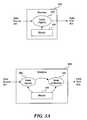
- FIG. 3Adepicts a diagram showing one example configuration of a node (nodes) controlled by a master residing on the same machine and dataflow therein from a data source to a data sink.
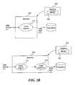
- FIG. 3Bdepicts a diagram showing one example configuration of a node controlled by a master residing on a different machine and dataflow therein from a data source to a data sink.
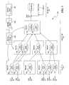
- FIG. 4depicts a diagram showing an example configuration of nodes in multiple tiers on the same machine controlled by multiple masters residing on different machines and dataflow therein from data sources to a data sink.
- FIG. 5depicts a diagram showing an example configuration of nodes in multiple tiers on different machines controlled by multiple masters residing on different machines and dataflow therein from data sources to a data sink.
- FIG. 6depicts a block diagram illustrating example components of a node through which dataflow occur.
- FIG. 7depicts a block diagram illustrating example components of a decorator module in a node.
- FIG. 8depicts a block diagram illustrating example components of a master that controls the nodes in the system.
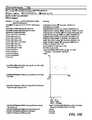
- FIG. 9depicts an example of an extensible data model used to represent events or data flow in a distributed system from a source to a sink.
- FIG. 10Adepicts a screenshot of an example user interface showing node status and configurations with node mappings.
- FIG. 10Bdepicts a screenshot of an example user interface for configuring a node.
- FIG. 10Cdepicts a screenshot of an example user interface for configuring multiple nodes.
- FIG. 10Ddepicts a screenshot of an example user interface for issuing raw commands.
- FIG. 10Edepicts a screenshot of an example user interface showing statistics for a node.
- FIG. 10Fdepicts a screenshot of an example user interface showing statistics for a node.
- FIG. 11depicts a flowchart of an example process of facilitating collecting and aggregating datasets that are machine or user-generated for analysis.
- FIG. 12depicts a flowchart of an example process for configuring a system to collect and aggregate datasets.
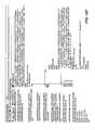
- FIG. 13depicts a flowchart of an example for scaling the system by implementing multiple masters on multiple machines.
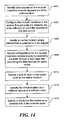
- FIG. 14depicts a flowchart of another example process for configuring a system to collect and aggregate datasets and to perform analytics on the datasets.
- FIG. 15depicts a flowchart of an example process for dynamically processing an event including a dataset that is streamed from a source to a sink via nodes.
- FIG. 16depicts a flowchart of an example process for collecting and aggregating datasets for storage in a file system with fault tolerance.
- FIG. 17depicts a flowchart of an example process for deleting the WAL in response to acknowledgement of receipt by the master.
- FIG. 18depicts a flowchart of an example process for collecting and aggregating datasets with fault tolerance using a store on failure mechanism.
- FIG. 19shows a diagrammatic representation of a machine in the example form of a computer system within which a set of instructions, for causing the machine to perform any one or more of the methodologies discussed herein, may be executed.
- Embodiments of the present disclosureinclude systems and methods for configuring a system to collect aggregate datasets.
- FIG. 1illustrates a block diagram of client devices 102 A-N that generate datasets (log data) to be collected and aggregated for storage in the storage device 108 via interacting nodes in various tiers, in some instances, through a network 106 .
- datasetslog data
- the client devices 102 A-Ncan be any system and/or device, and/or any combination of devices/systems that is able to establish a connection with another device, a server and/or other systems.
- the client devices 102 A-Ntypically include display or other output functionalities to present data exchanged between the devices to a user.
- the client devices and content providerscan be, but are not limited to, a server desktop, a desktop computer, a thin-client device, an interne kiosk, a computer cluster, a mobile computing device such as a notebook, a laptop computer, a handheld computer, a mobile phone, a smart phone, a PDA, a Blackberry device, a Treo, and/or an iPhone, etc.
- the client devices 102 A-Nare coupled to a network 106 .
- the client devicesmay be directly connected to one another.
- usersinteract with user devices 102 A-N (e.g., machines or devices).
- the devices 102 A-Ncan generate datasets such as log files to be collected and aggregated.
- the filecan include logs, information, and other metadata about clicks, feeds, status updates, data from applications, and associated properties and attributes.
- User devices 102 A-Ncan have nodes executing or running thereon that collect the datasets that are user-generated or machine-generated, for example, based on user-interaction with applications or websites running on the devices. Such nodes can interact and/or communicate with one or more other nodes (e.g., either running on the same device/machine or another device/machine (e.g., machine/device 104 ) to facilitate collection and aggregation of datasets thus generated.
- the datasetsare eventually written to a file and stored, for example, in storage (e.g., repository 130 ) on a physical disk.
- the dataflow among nodescan be configured at a master.
- the nodes executed on the machines 102 or 104can contact the master(s) to obtain configuration information, which have been set by default or configured by a user
- the mastercan be executed on the same devices 102 A-N, 104 , or at the host device 100 .
- One or multiple masterscan be involved in the mapping of data flow among the nodes and various machines.
- FIG. 2-5Some examples of architectural configurations among nodes, machines, and masters are illustrated and described with further reference to the example of FIG. 2-5 .
- the functionalities of the nodes and configurationare described with further reference to the examples of FIG. 6-8 .
- the network 106over which the client devices 102 A-N, 104 , host, and the nodes and masters therein communicate may be a telephonic network, an open network, such as the Internet, or a private network, such as an intranet and/or the extranet.
- the Internetcan provide file transfer, remote log in, email, news, RSS, and other services through any known or convenient protocol, such as, but is not limited to the TCP/IP protocol, Open System Interconnections (OSI), FTP, UPnP, iSCSI, NSF, ISDN, PDH, RS-232, SDH, SONET, etc.
- OSIOpen System Interconnections
- the network 106can be any collection of distinct networks operating wholly or partially in conjunction to provide connectivity to the client devices, host server, and may appear as one or more networks to the serviced systems and devices.
- communications to and from the client devices 102 A-Ncan be achieved by, an open network, such as the Internet, or a private network, such as an intranet and/or the extranet.
- communicationscan be achieved by a secure communications protocol, such as secure sockets layer (SSL), or transport layer security (TLS).
- SSLsecure sockets layer
- TLStransport layer security
- Internetrefers to a network of networks that uses certain protocols, such as the TCP/IP protocol, and possibly other protocols such as the hypertext transfer protocol (HTTP) for hypertext markup language (HTML) documents that make up the World Wide Web (the web).
- HTTPhypertext transfer protocol
- HTMLhypertext markup language
- a web serverwhich is one type of content server, is typically at least one computer system which operates as a server computer system and is configured to operate with the protocols of the World Wide Web and is coupled to the Internet.
- the physical connections of the Internet and the protocols and communication procedures of the Internet and the webare well known to those of skill in the relevant art.
- the network 106broadly includes anything from a minimalist coupling of the components illustrated in the example of FIG. 1 , to every component of the Internet and networks coupled to the Internet.
- communicationscan be achieved via one or more wireless networks, such as, but is not limited to, one or more of a Local Area Network (LAN), Wireless Local Area Network (WLAN), a Personal area network (PAN), a Campus area network (CAN), a Metropolitan area network (MAN), a Wide area network (WAN), a Wireless wide area network (WWAN), Global System for Mobile Communications (GSM), Personal Communications Service (PCS), Digital Advanced Mobile Phone Service (D-Amps), Bluetooth, Wi-Fi, Fixed Wireless Data, 2G, 2.5G, 3G networks, enhanced data rates for GSM evolution (EDGE), General packet radio service (GPRS), enhanced GPRS, messaging protocols such as, TCP/IP, SMS, MMS, extensible messaging and presence protocol (XMPP), real time messaging protocol (RTMP), instant messaging and presence protocol (IMPP), instant messaging, USSD, IRC, or any other wireless data networks or messaging protocols.
- LANLocal Area Network
- WLANWireless Local Area Network
- PANPersonal area network
- CANCampus area network
- MANMetropolitan area network
- the client devices 102 A-Ncan be coupled to the network (e.g., Internet) via a dial up connection, a digital subscriber loop (DSL, ADSL), cable modem, and/or other types of connection.
- the client devices 102 A-Ncan communicate with remote servers (e.g., web server, host server, mail server, and instant messaging server) that provide access to user interfaces of the World Wide Web via a web browser, for example.
- remote serverse.g., web server, host server, mail server, and instant messaging server
- the repository 130can store software, descriptive data, images, system information, drivers, collected datasets, aggregated datasets, log files, analytics of collected datasets, enriched datasets, etc.
- the repositorymay be managed by a database management system (DBMS), for example but not limited to, Oracle, DB2, Microsoft Access, Microsoft SQL Server, MySQL, FileMaker, etc.
- DBMSdatabase management system
- the repositoriescan be implemented via object-oriented technology and/or via text files, and can be managed by a distributed database management system, an object-oriented database management system (OODBMS) (e.g., ConceptBase, FastDB Main Memory Database Management System, JDOlnstruments, ObjectDB, etc.), an object-relational database management system (ORDBMS) (e.g., Informix, OpenLink Virtuoso, VMDS, etc.), a file system, and/or any other convenient or known database management package.
- OODBMSobject-oriented database management system
- ORDBMSobject-relational database management system
- the repositoryis managed by a distributed file system or network file system that allows access to files from multiple hosts/machines over a network.
- the distributed file systemcan include by way of example, the Hadoop Distributed File system (HDFS).
- HDFSHadoop Distributed File system
- file systemscan be used as well, for example, through integration of Hadoop's interface which provides an abstraction layer for the file system.
- a local file system where a node residescan be used.
- the HDFS native distributed file systemcan also be used.
- S3a remote file system hosted by Amazon web services
- FTPa remote file system hosted by Amazon web services
- KFSKosmos file system—another distributed file system
- Clientscan also write to different file systems (NFS), or other file systems.
- NFSfile systems
- the user devices 102 and 104are able to write files (e.g., files including by way of example, collected and aggregated datasets/logs/log files) to the repository 130 , either through the network 106 or without utilizing the network 106 .
- the host server 100can be implemented on a known or convenient computer system, such as is illustrated in FIG. 19 .
- FIG. 2Adepicts a diagram showing one example configuration 200 of nodes 202 and 204 that are controlled/configured by a master 206 and dataflow therein from a data source 201 to a data sink 207 (e.g., repository 208 ).
- a data sink 207e.g., repository 208
- the node 202can be mapped to the data source 201 on the machine that generates that dataset.
- the datasetcan include data, metadata, complex data, including logs of clicks, social networking sites, feeds, status updates, logs from local or remote applications, etc.
- the data sourcecan include, by way of example, but not limitation, a syslog port, an incoming network connection, and an IRC channel, output from execution of a program, a text file.
- a data sourcecan include a Hadpp sequence file formatted file.
- the node 202can map the data source 201 to a receiving location such as a data sink 203 .
- a master 206controls the mapping of the data source 201 to the receiving location 203 via the node 202 .
- data flow of the dataset from the data source 201 to the receiving location 203is configurable and reconfigurable at the master 206 by a user (e.g., system administrator, developer, etc.).
- the node 202can contact the master 206 to obtain its mapping/configuration information.
- nodescontact the master 206 to obtain configuration information allows node configuration to dynamically change without having to login and to restart the daemon (e.g., a server process on a UNIX-based machine).
- the node's configurationcan be changed to a new one without taking the system offline.
- nodesare configured using a web interface to the master. Screenshots of example interfaces are illustrated with further reference to the example of FIG. 10 .
- one or more masterscan be implemented using one or more machines, as illustrated in subsequent figures.
- the master 206can be executed on the machine on which the collected dataset is received or generated or one or more different machines. Different types of architectural configurations for the master 206 are illustrated in subsequent figures.
- a receiving locationcan include, by way of example, not limitation, a network connection, a physical disk, a console, a text file.
- the receiving locationcan also include, a file in the Hadoop sequence file format, an HDFS path, a port, a monitoring or alerting application, and/or an IRC.
- the collected dataset from the data source 201can be aggregated at the receiving location (data sink 203 ).
- the receiving locatione.g., or data sink 203
- analyticscan be performed on the dataset upon collection at node 202 and/or aggregation at node 204 .
- the master 206controls the functions/properties of the nodes 202 and/or 204 .
- the nodes 202 / 204can be associated with properties and/or functions, including but not limited to, adding encryption or digital signature, performing batching/unbatching, performing compression/uncompression, generating a checksum of a dataset, performing sampling, performing benchmarking (e.g., by injecting benchmark tags).
- the analytic that are performedcan include, feature extraction, filtering, transformation, generating aggregate counts, statistics, etc.
- the node 204in aggregating the dataset, can also be mapped to a data source 205 and a data sink 207 , as controlled and configured at the master 206 .
- the data source 205 of the node 204can be mapped to the sink 203 of node 202 . Additional functions and properties of nodes are illustrated with further reference to the example of FIG. 6-7 .
- the node 204(e.g., a collector node) writes the aggregated data to a storage location.
- the storage locationcan be localized or distributed among multiple machines and the dataset is stored redundantly.
- the data sink 207 of the node 204can be mapped to a repository 208 , by the master 206 , for example.
- the repository 208may be managed by a file system.
- the file systemcan be distributed (e.g., the Hadoop Distributed File System (HDFS)).
- HDFSHadoop Distributed File System
- node 202although illustrated in the example of FIG. 2A as having being mapped to a single node 204 , can be mapped to multiple nodes, as further illustrated in the example of FIG. 2B .
- FIG. 2Bdepicts diagrams showing examples of configuration of nodes controlled/configured by a master and the dataflow therein from a data source to a data sink.
- an agent node 212can send incoming dataset/event from a data source 211 to multiple collector nodes (e.g., node 214 and node 216 ) which further maps the data flow to the repository 218 .
- the collector nodesare failover nodes for handling failures when appending new events. Failover sinks can be used to specify alternate collectors to contact in the event the assigned collector fails. Fail over sinks can also be used to specify a local disk sink to store data until the assigned collector recovers. For example, if node 214 goes down, the agent node 212 can deliver events via collector agent 216 to the repository 218 or any other receiving location or destination.
- the collector 216can queue their logs until node 214 comes back online.
- the failover assignmentcan be specified through the master 220 .
- the failover mechanismis built in by default by disbursing collector node assignments evenly among agent nodes. This can mitigate the chances of one collector from being overloaded when one collector fails.
- multiple collectors 224are assigned to receive events/data flow from agent node 222 .
- the collectors 224can store the event/data flow in the repository 228 .
- the collectors 224may be failover chains.
- the collectors 224can be fan out sinks, each of which receives the incoming event from the data source 221 .
- the fan out sinkscan be configured by the master 230 as collectors 224 .
- the multiple collectors 224 as fan out sinkscan be used for data replication for processing data off a main data flow path.
- FIG. 3Adepicts a diagram showing one example configuration of a node (nodes) controlled by a master 306 residing on the same machine 300 and dataflow therein from a data source 301 to a data sink 305 .
- the agent node 302 and the master 306 used for controlling, configuring, and/or monitoring the node 302can be implemented on the same machine 300 .
- the master 306can be used to specify functions and/or properties of the agent node 302 in sending an incoming event/data set from the source 310 to the sink 305 .
- a collector node 304is also implemented on the same machine 304 as the agent node 302 and the master 306 .
- the master 306can control, configure, and/or monitor both nodes 302 and 304 in mapping events/data flow fro the source 301 to the sink 305 .
- FIG. 3Bdepicts a diagram showing example configurations of a node 312 or nodes 312 and 314 executed on a machine 320 and controlled by a master 316 which is executed on a different machine 330 and dataflow therein from a data source 311 to a data sink 315 .
- the master 316 executed on machine 330controls, configures, and/or monitors the node 312 on the machine 320 in sending data sets/events from the data source 311 to the data sink 315 .
- the collector node 314 which is mapped to receive datasets/events from the node 312can also be executed on machine 320 .
- the collector nodecan be configured to send datasets received from the node 312 to a data sink 315 .
- the master 316can also control, configure, and/or monitor the collector node 314 .
- having a single masteris a single point of failure in the system. If the master 316 fails, the ability to update nodes (e.g., nodes 314 and/or 314 ), configure nodes, control, and/or monitor nodes, etc. goes down.
- nodese.g., nodes 314 and/or 314
- configure nodes, control, and/or monitor nodes, etc.goes down.
- multiple masterscan be implemented on multiple machines to maintain a consistent state in the system.
- using multiple masters on multiple machinesallows the system to scale with increasing amount of log data and events to process and analyze.
- using multiple collectorscan also increase log collection throughput and can improve timeliness of event/dataset delivery since more collector nodes are available at any given time during operation. Since data collection is parallelizable, the load from agent nodes can be shared and distributed among many collector nodes. Example architectures with multiple masters and multiple collectors are illustrated in FIG. 4-5 .
- FIG. 4depicts a block diagram showing an example configuration of nodes in multiple tiers on the same machine 400 which controlled by multiple masters 406 and 408 residing on different machines 420 and 430 respectively, and dataflow therein from data sources 401 , 403 , and 405 to a data sink 407 .
- the example system of FIG. 4utilizes multiple agent nodes 402 in an agent tier 412 and multiple collector nodes 404 in a collector tier 414 .
- the nodes 402 in the agent tier 412are located on the machine 400 which is also producing logs that are being collected.
- the data source 401 of the node 402can be configured to be a port on the machine 400 .
- the sink of the node 402can be configured to be node 404 in the collector tier 414 .
- collector nodes 404can listen and receive data from multiple agent nodes 412 and aggregate logs. In addition, collector nodes 414 can further write the logs to a data sink 407 in the storage tier 416 .
- agent nodesIn reliable mode agent nodes generally write data to the respective local disks. This data might not be deleted until after it knows that the data has reached its final destination. Collectors generally don't write to their local disk—they actually forward data to the storage tier which eventually points the collector to storage tier nodes that write to storage tier disks.
- An agentis generally on a system that is responsible for doing other work (serving web pages) and thus agent nodes typically strive to have low resource utilization (e.g., cpu, memory, disk).
- Collector nodesare generally dedicated to processing large amounts of data and can use more expensive algorithms because its processing units are generally less occupied with other tasks.
- the data sink 407may or may not be a storage unit/device.
- the collector nodes 404can also send the data sets downstream to cluster for further processing, a network, etc.
- FIG. 5depicts a diagram showing an example configuration of nodes 502 and 504 in multiple tiers on different machines controlled by multiple masters 506 residing on different machines and dataflow therein from data sources 501 to a data sink 507 .
- Agent nodes 502can be executed on different machines and map incoming data/events to collector nodes 504 .
- the multiple machinesmay be in a cluster and can include web servers.
- the multiple machinesgenerate the log data to be collected and each of the multiple machines is associated with at least one agent node to facilitate data collection and/or aggregation.
- the agent nodes 502can forward the collected log data or events to a collector tier 512 which includes at least one collector node 504 but in some instances, multiple collector nodes 504 which can combine streams of log data/events into larger streams, for example, for writing to the storage tier 516 .
- the collector node(s) 504can aggregate the log data collected from the machines on which the agent nodes are executed.
- the collector nodes 504can also be executed on different machines with each machine having various numbers of collector nodes 504 , which passes events on to the data sink 507 .
- the collector node(s) 504outputs the log data to multiple destinations in the same or different formats.
- Some of the supported formatsinclude, by way of example not limitation, raw text file, json (a web format), avro binary (an apache serialization format), a hadoop native sequence file, text emulating a syslog formatted entry, an apache web server formatted entry, and a “log4j” formatting pattern, etc.
- File formatsare the format for batches of records. Record formats are the formatting for individual events/records. A collector writing to storage tier can be responsible for file formats. The work for formatting individual records however can be pushed upstream.
- One embodiment of the topologyincludes a storage tier 516 having a storage system coupled to the machines in the system.
- the storage systemcan include a distributed file system to which the collector node(s) 504 in the collector tier 514 stores the log data aggregated from the set of machines in the system.
- analyticscan be performed on the log data/aggregated events by the agent nodes 502 and/or the collector nodes 504 .
- the master 506can be used to control/configure the types of analytics that are performed.
- Agent nodes 502 and collector nodes 504can be configured, re-configured via the masters 506 , which can be executed on multiple machines that are different from the machines that the collector 504 and agent nodes 502 are executed on.
- the masters 506specify the configuration/topology of the system 500 and the agent node(s) 502 and the collector node(s) 504 contact the master 506 to retrieve configuration information.
- the master 506can specify that an agent data sink for the agent node 502 is a collector data source for the collector node 504 in the collector tier 514 and that a collector data sink 507 for the collector node 504 is the distributed file system in the storage tier 516 .
- the master 506can be used by a user to configure or reconfigure the agent data sink and agent data source and/or to configure or reconfigure the collector data source and the collector data sink.
- FIG. 6depicts a block diagram illustrating example components of a node 602 through which dataflow occur.
- the node 602can include a source specifier module 604 , a sink specifier module 606 , a configuration file 610 , and/or a decorator module 620 .
- a “module” or an “engine”includes a dedicated or shared processor and, typically, firmware or software modules that are executed by the processor. Depending upon implementation-specific or other considerations, an engine can be centralized or its functionality distributed. An engine can include special purpose hardware, firmware, or software embodied in a computer-readable medium for execution by the processor.
- a computer-readable mediumis intended to include all mediums that are statutory (e.g., in the United States, under 35 U.S.C. 101), and to specifically exclude all mediums that are non-statutory in nature to the extent that the exclusion is necessary for a claim that includes the computer-readable medium to be valid.
- Known statutory computer-readable mediumsinclude hardware (e.g., registers, random access memory (RAM), non-volatile (NV) storage, to name a few), but may or may not be limited to hardware.
- the nodeincludes a source specifier module 604 and a sink specifier module 606 .
- the source specifier module 604 and sink specifier module 606can be implemented, example, as software embodied in a computer-readable medium or computer-readable storage medium on a machine, in firmware, in hardware, in a combination thereof, or in any applicable known or convenient device or system.
- This and other modules or engines described in this specificationare intended to include any machine, manufacture, or composition of matter capable of carrying out at least some of the functionality described implicitly, explicitly, or inherently in this specification, and/or carrying out equivalent functionality.
- the source specifier module 604can include an identifier or mapper to a source that produces or accepts events or data fed into the system.
- the node 604reads or tails the event source.
- the module 604can detect, recognize, identify, and/or store a port ID (e.g., a port name, a TCP or UDP port, port number) and a file ID (e.g., a file name, a file path, etc.).
- the filecan be any type of file, including but not limited to, messages, system log files, Hadoop log files, text files, etc.
- the event sourcecan include, a console, a sequence file (e.g., serialized events in a sequence file format), a source that synthetically generates a specified number of messages of a select size.
- the sink specifier module 606includes an identifier or mapper to a location that consumes data or an event (e.g., a receiving or destination location for data or events).
- a sinkcan include, by way of example, a disk, a repository, a distributed file system on a disk (e.g., the Hadoop distributed file system), a console, a device/machine, and/or a network/network connection over which the data/event is to be forwarded over.
- the sink specifier module 606can detect, recognize, identify, and or store, a machine/device ID, a port ID, a file ID, and/or a path ID.
- the path IDis a distributed sequence file path.
- the source and sink specifier modulescan store or retrieve the configuration information stored in the configuration file 610 .
- the configuration file 610may be loaded with default values upon installation.
- the configuration file 610may be updated by a master that controls the node 602 . The updates the configuration file 610 may occur while the system is running or when the system is off.
- the node 602may be assigned to have an agent role or a collector rule.
- an agent nodeis co-located on machines/devices with the service/application that is generating, producing, creating events/logs/data.
- a collector nodecan receive, accept, check, listen for data from one or more agent nodes.
- a collector nodecan be mapped to the data sink of an agent node, for example, to aggregate logs/data and/or to extract analytics.
- a collector nodecan further write the dataset, events, and/or any generated events to storage (e.g., a distributed file system).
- the node 602includes a decorator module 620 .
- the decorator module 620can be implemented, example, as software embodied in a computer-readable medium or computer-readable storage medium on a machine, in firmware, in hardware, in a combination thereof, or in any applicable known or convenient device or system. This and other modules or engines described in this specification are intended to include any machine, manufacture, or composition of matter capable of carrying out at least some of the functionality described implicitly, explicitly, or inherently in this specification, and/or carrying out equivalent functionality.
- the decorator module 620can add properties/functionalities of a sink and modify the data/event streams that pass through them, like a wrapper. For example, the decorator module 620 can be used to increase reliability, robustness of the system or to perform analytics.
- a decoratorcan correspond to a sink that interposes between the source and the sink.
- the decoratorprocesses events and then sends it down the pipeline to another sink (which may be another decorator wrapping another sink) on the same node/dataflow.
- Sourcesproduce events, and pass them through the decorator to sink.
- FIG. 7depicts a block diagram illustrating example components of a decorator module 720 in a node.
- the decorator module 720can include, a write ahead module 702 , a sampler module 704 , an open module 706 , an append module 708 , a batch/unbatch module 710 , and/or a GZIP/GUNZIP module 712 .
- a “module” or an “engine”includes a dedicated or shared processor and, typically, firmware or software modules that are executed by the processor. Depending upon implementation-specific or other considerations, an engine can be centralized or its functionality distributed. An engine can include special purpose hardware, firmware, or software embodied in a computer-readable medium for execution by the processor.
- a computer-readable mediumis intended to include all mediums that are statutory (e.g., in the United States, under 35 U.S.C. 101), and to specifically exclude all mediums that are non-statutory in nature to the extent that the exclusion is necessary for a claim that includes the computer-readable medium to be valid.
- Known statutory computer-readable mediumsinclude hardware (e.g., registers, random access memory (RAM), non-volatile (NV) storage, to name a few), but may or may not be limited to hardware.
- the decorator module 720includes a write ahead module 702 .
- the decorator module 620can be implemented, example, as software embodied in a computer-readable medium or computer-readable storage medium on a machine, in firmware, in hardware, in a combination thereof, or in any applicable known or convenient device or system.
- This and other modules or engines described in this specificationare intended to include any machine, manufacture, or composition of matter capable of carrying out at least some of the functionality described implicitly, explicitly, or inherently in this specification, and/or carrying out equivalent functionality.
- the write ahead module 702provides reliability and durability and writes/stores events/datasets to persistent storage on the machine generating the event (writeAhead( . . . )) prior to forwarding them. In the event and any of the downstream nodes fails, the system has a copy of the dataset that can still be retrieved. In response to determining that the dataset/event has safely reached its destination, the copy can be deleted from persistent storage.
- the write ahead module 702can also assign batch identifiers for batches of messages/events to track
- the decorator module 720includes a sampler module 704 .
- the decorator module 704can be implemented, example, as software embodied in a computer-readable medium or computer-readable storage medium on a machine, in firmware, in hardware, in a combination thereof, or in any applicable known or convenient device or system.
- This and other modules or engines described in this specificationare intended to include any machine, manufacture, or composition of matter capable of carrying out at least some of the functionality described implicitly, explicitly, or inherently in this specification, and/or carrying out equivalent functionality.
- the sampler module 704can sample data input or events at select intervals (e.g., intervalSampler(N)). For example, the sample module 704 can be configured to send every nth element/event from the source to the data sink. In one embodiment, the sampler module 704 samples based on a probability such that each event or message has a specified chance of being forwarded (e.g., probSampler (p)). In addition, the sampler module 704 can be a reservoir sampler (e.g., reserverSampler (K) such that when flushed, a selected number (K) of elements are forwarded and each event that passes through has the same probability of being selected for forwarding.
- a reservoir samplere.g., reserverSampler (K) such that when flushed, a selected number (K) of elements are forwarded and each event that passes through has the same probability of being selected for forwarding.
- the decorator module 720includes an open module 706 (or re-try open module).
- the open module 706can be implemented, example, as software embodied in a computer-readable medium or computer-readable storage medium on a machine, in firmware, in hardware, in a combination thereof, or in any applicable known or convenient device or system.
- This and other modules or engines described in this specificationare intended to include any machine, manufacture, or composition of matter capable of carrying out at least some of the functionality described implicitly, explicitly, or inherently in this specification, and/or carrying out equivalent functionality.
- the open module 706in reading or opening a file or incoming event, continues to re-try the opening process if the initial attempt fails.
- the decorator module 720includes an append module 708 (or re-try append module).
- the append module 708can be implemented, example, as software embodied in a computer-readable medium or computer-readable storage medium on a machine, in firmware, in hardware, in a combination thereof, or in any applicable known or convenient device or system.
- This and other modules or engines described in this specificationare intended to include any machine, manufacture, or composition of matter capable of carrying out at least some of the functionality described implicitly, explicitly, or inherently in this specification, and/or carrying out equivalent functionality.
- the append module 708can append events to a target. In the event that the append fails, the module 708 can close the target, re-open it and attempt to append again.
- sinks and decorator modulesinclude open, append, and close functions. Typically, if one of these operations fail, the modules can give up after a first try.
- the sink/decoratorcan be configured to keep trying the failed operation (e.g.,retry opening or appending).
- the decorator module 720includes a batch/unbatch module 710 .
- the batch/unbatch module 710can be implemented, example, as software embodied in a computer-readable medium or computer-readable storage medium on a machine, in firmware, in hardware, in a combination thereof, or in any applicable known or convenient device or system.
- This and other modules or engines described in this specificationare intended to include any machine, manufacture, or composition of matter capable of carrying out at least some of the functionality described implicitly, explicitly, or inherently in this specification, and/or carrying out equivalent functionality.
- the batch/unbatch module 710can buffer a select number of events/message together to be forwarded or sent as a single aggregate event.
- the batch/unbatch module 710can take an aggregate event and split and forward the original events.
- the decorator module 720includes a GZIP/GUNZIP module 712 .
- the GZIP/GUNZIP module 712can be implemented, example, as software embodied in a computer-readable medium or computer-readable storage medium on a machine, in firmware, in hardware, in a combination thereof, or in any applicable known or convenient device or system. This and other modules or engines described in this specification are intended to include any machine, manufacture, or composition of matter capable of carrying out at least some of the functionality described implicitly, explicitly, or inherently in this specification, and/or carrying out equivalent functionality.
- the GZIP/ZIP module 712can zip or unzip an event/message or multiple events/messages.
- multiple decoratorscan be assigned to an event, message, or dataset.
- decoratorscan be combined to batch multiple messages together and compress the messages before forwarding them to the mapped data sink.
- FIG. 8depicts a block diagram illustrating example components of a master 800 that controls the nodes in the system.
- the master 800can include a node configurator module 802 , a system health monitor 804 , a consistency manager 806 , a map module 808 , and/or an acknowledger module 810 .
- the master 800can include additional or less modules.
- the master 800although illustrated as being a discrete component, can be implemented on multiple machines, as shown in the examples of FIG. 4-5 on full or partial redundancy.
- the master 800as implemented on a single or multiple machines can perform as a central control and monitor for the system.
- the master 800can track and monitor the status, health of nodes, and the data flow in the system. In tracking and monitoring system status, the master 800 can automatically perform any system re-configurations that may be needed to resolve node failure or load imbalance, for example.
- the master 800can identify, detect, or be used to specify new nodes or deleted nodes in the system and perform any adjustments in data flow by updating the mapping of data sinks and sources.
- the nodescontact the master 800 to retrieve configuration information.
- the nodedetects that the configuration version has been changed and can instantiate and activate the configuration. This allows updates to the system and mapping to be performed in dynamically, in operation, without starting or rebooting the system. For example, a node's configuration can be updated during operation.
- a usercan reconfigure the setting by accessing the master 800 .
- One of accessing the master 800is through the master's web page. Examples of screenshots are illustrated in FIG. 10A-F .
- the configuration linkis displayed on the master's web interface. In the interface, for example, node names are depicted and sources and sinks can be viewed, updated, or deleted. Once a configuration has been changed, the version identifier or stamp on the master's web page will be updated.
- a “module” or an “engine”includes a dedicated or shared processor and, typically, firmware or software modules that are executed by the processor. Depending upon implementation-specific or other considerations, an engine can be centralized or its functionality distributed. An engine can include special purpose hardware, firmware, or software embodied in a computer-readable medium for execution by the processor.
- a computer-readable mediumis intended to include all mediums that are statutory (e.g., in the United States, under 35 U.S.C. 101), and to specifically exclude all mediums that are non-statutory in nature to the extent that the exclusion is necessary for a claim that includes the computer-readable medium to be valid.
- Known statutory computer-readable mediumsinclude hardware (e.g., registers, random access memory (RAM), non-volatile (NV) storage, to name a few), but may or may not be limited to hardware.
- the masterincludes a node configurator module 802 .
- the node configurator module 802can be implemented, example, as software embodied in a computer-readable medium or computer-readable storage medium on a machine, in firmware, in hardware, in a combination thereof, or in any applicable known or convenient device or system.
- This and other modules or engines described in this specificationare intended to include any machine, manufacture, or composition of matter capable of carrying out at least some of the functionality described implicitly, explicitly, or inherently in this specification, and/or carrying out equivalent functionality.
- the node configurator module 802detects, updates, identifies, stores configuration settings of the nodes in the system. For example, the source and sink mappers can configure the data source(s) and/or data sink(s) for each node. In addition, the module 802 can assign and/or track functions/properties (e.g., analytics functions) that a node can perform.
- the source and sink mapperscan configure the data source(s) and/or data sink(s) for each node.
- the module 802can assign and/or track functions/properties (e.g., analytics functions) that a node can perform.
- the masterincludes a system health monitor 804 .
- the system health monitor 804can be implemented, example, as software embodied in a computer-readable medium or computer-readable storage medium on a machine, in firmware, in hardware, in a combination thereof, or in any applicable known or convenient device or system.
- This and other modules or engines described in this specificationare intended to include any machine, manufacture, or composition of matter capable of carrying out at least some of the functionality described implicitly, explicitly, or inherently in this specification, and/or carrying out equivalent functionality.
- the system health monitor 804can track, detect, determine, monitor, system traffic, node health/status, dataflow, load balance/imbalance in the system.
- the master 800can update/adjust data flow based on system traffic and any load imbalances. In addition, if certain nodes have failed, the master 800 can assign failover nodes such that data flow is not interrupted.
- the masterincludes a consistency module 806 .
- the consistency module 806can be implemented, example, as software embodied in a computer-readable medium or computer-readable storage medium on a machine, in firmware, in hardware, in a combination thereof, or in any applicable known or convenient device or system.
- This and other modules or engines described in this specificationare intended to include any machine, manufacture, or composition of matter capable of carrying out at least some of the functionality described implicitly, explicitly, or inherently in this specification, and/or carrying out equivalent functionality.
- the consistency module 806maintains consistency among multiple masters implemented on multiple machines in a system, by leveraging the consensus protocol and/or a gossip protocol.
- the master 800can maintain consistency using a consensus protocol for order critical state changes and using a gossip protocol for weak consistency among data including but not limited to node status updates, reporting information, and metrics information.
- the masterincludes a map module 808 and an acknowledger module 810 .
- the map module 808 and the acknowledger module 810can be implemented, example, as software embodied in a computer-readable medium or computer-readable storage medium on a machine, in firmware, in hardware, in a combination thereof, or in any applicable known or convenient device or system.
- This and other modules or engines described in this specificationare intended to include any machine, manufacture, or composition of matter capable of carrying out at least some of the functionality described implicitly, explicitly, or inherently in this specification, and/or carrying out equivalent functionality.
- the map module 808monitors and manages a set of tags associated with batches of messages to track which messages or batches or messages have been successfully sent to a receiving location or stored in a data repository.
- an agent nodegenerates a batch comprising multiple messages from the log data and assigns a tag (e.g., can include a begin event tag and an end event tag) to the batch.
- the agentcan also compute a checksum for the batch of multiple messages and stores he tag and the checksum to a write-ahead-log (WAL) in persistent storage of the machine from which the dataset was generated.
- WALwrite-ahead-log
- the agent nodesends the batch of messages to a collector which verifies the checksum of the batch, and if successful, adds the tag to a map of tags for batches of messages.
- the collector agentpublishes the tag to the map module 808 of the master.
- the map module 808includes identifiers for events, messages, or batches of messages that have reached their mapped locations.
- the master 800can use the identifiers in the map module 808 to notify the agent nodes of batches that have been successfully stored or sent.
- the acknowledger module 810using the tags that are associated with batches in the map, acknowledges the agent node and the collector node of the batches that have been safely stored in the file system or sent down stream.
- FIG. 9depicts an example of an extensible data model used to represent events or data flow in a distributed system from a source to a sink.
- the data modelcan include one or more timestamp fields 902 and 904 , a priority field 906 , a source host field 908 , a body field 910 , and/or a metadata table field 912 .
- the data modelis extensible and thus additional fields can be added on the fly during data flow. The data model is described with further reference to the example of FIG. 15 .
- FIG. 10Adepicts a screenshot of an example user interface showing node status and configurations with node mappings. This user interface can be accessed from the master.
- FIG. 10Bdepicts a screenshot of an example user interface for configuring a node.
- the configuration pagecan be accessed from the master's web page. For example, a node to be configured can be selected from the list and its source/sink can be specified.
- FIG. 10Cdepicts a screenshot of an example user interface for configuring multiple nodes.
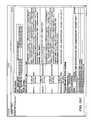
- FIG. 10Ddepicts a screenshot of an example user interface for issuing raw commands.
- Commandscan be used to modify the global state of the system.
- the “config” commandsets the configuration of a flow on the master, who in turn sends the info to a node.
- the “refresh” commandtakes an existing config and forces the node to reset (close then open).
- the “decommission” commandremoves a logical node.
- the “unmap” commandremoves a logical node from a physical node.
- the “spawn” commandcreates a new logical node (could be used to associate an unmapped logical node onto another physical machine).
- FIG. 10Edepicts a screenshot of an example user interface showing statistics for a node.
- the user interfaceshows the data flow configuration settings, and memory usage of a particular node.
- this figureshows information about the node “LogicalNode[0]” and includes two analytics reports: a graph showing the number of incoming events and a graph showing a histogram of the frequency of certain words in the stream.
- the source in this exampleis Twitter, and the sinks for the node include the graphs.
- FIG. 10Fdepicts a screenshot of an example user interface showing statistics for a node. This figure illustrates the configuration info for this data flow, and similarly has an event graph and a histogram (showing an even distribution of substrings).
- FIG. 11depicts a flowchart of an example process of facilitating collecting and aggregating datasets that are machine or user-generated for analysis.
- a datasetis collected on a machine on which the dataset is received or generated.
- the data setcan include logs from an application that is local or remote, a service, a social networking site, feeds, status updates, etc.
- the datasetcan be collected from a data source on the machine.
- datasetscan be collected from machines in a cluster which can include web servers, for example.
- the dataset that is collected from the data sourceis aggregated at a receiving location.
- the receiving locationcan be, for example, a network, a network connection, a physical disk, a consol, a text file, a file in a sequence file format, an HDFS path, a port, a monitoring or alerting application, and/or an IRC.
- One or more receiving locationcan be specified.
- the mapping of the data source to the receiving locationis controlled by a master.
- the mastercan be executed on a different machine than the machine on which the dataset is generated or received.
- the mastercan also be executed on the same machine as the one on which the dataset is received or generated.
- the data sourceis mapped to a receiving location via a logical node.
- the logical nodecan contact the master to obtain configuration information including but not limited to, functions, data source, data sink, etc.
- analyticsare performed on the dataset upon collection or aggregation. Analytics that can be performed include, by way of example, feature extraction, filtering, and transformation, generation of aggregate counts, and/or generation of statistics.
- the analyticscan be performed in near real time relative to collection of the dataset.
- the dataset aggregated at the receiving locationis written to a storage location.
- IOthere is typically a tradeoff between throughput and latency.
- sending lots of small thingswill take a lot longer than a few large things, even if the actual amount of payload is the same. This is generally due to overhead associated with each sent value (sent events in Flume's case).
- delaycan be added to help the scheduler improve on throughput.
- the storage locationcan be distributed among multiple machines and the dataset is stored redundantly on a distributed file system
- FIG. 12depicts a flowchart of an example process for configuring a system to collect and aggregate datasets.
- a cliente.g., a web page/interface or a command line interface, another program (a master), or a device (e.g., a laptop, a cell phone, a smartphone, iPhone, etc.) is launched on a machine to access a master for the system, for example, using the master's universal resource locator (URL).
- the master's web pagecan be used to view, change, and/or update a node's configuration, as illustrated in the example of FIG. 10A .
- the systemmay include multiple machines (e.g., in a cluster) which generate datasets that are to be collected.
- a data source in the system from where dataset is to be collectedis identified.
- a machine in the system that generates the dataset to be collectedis configured to send the dataset to the data source.
- an arrival location where the dataset that is collected is to be aggregated or writtenis identified.
- an agent nodeis configured by specifying a source for the agent node as the data source in the system and specifying a sink for the agent node as the arrival location.
- the agent nodeis generally configurable to perform analytics on the dataset.
- the arrival locationis specified as a collector source of a collector node.
- a distributed file systemis specified as a collector sink of the collector node.
- the distributed file systemcan be, for example, the Hadoop distributed file system (HDFS)
- FIG. 13depicts a flowchart of an example for scaling the system by implementing multiple masters on multiple machines.
- a masterprovides a centralized management point to monitor and update data flows. Changes in the system are told to the master, and changes can come from the master. When new resources are added to the system, the information is updated at the master. In addition, if a user issues a command that changes global state, the master can be used such that the master can react to these state changes. In addition, the master can dynamically respond to system changes such as load imbalances, node failure, machine failure, new hardware, etc. For example, a user configures a new node to be a collector. The master detects this, and automatically reacts by changing the configuration of some nodes to send events downstream to the new collector. The master can do this by changing global state.
- a collector nodehasn't communicated with the master for a while.
- the mastermay decide that the machine might have fialed and automatically reacts by sending an event to an admin (via email/irc/im/sms, etc.).
- nodesperiodically report their performance metrics to the master (e.g., in the examples of FIGS. 10E, 10F ). The reports indicate that a collector is being overloaded with work, and reacts to new metrics data by shifting some of the work from the overloaded collector to another with less load. This can be performed by changing global state.
- Nodes in the systemcan be configured/reconfigured dynamically via the master.
- the nodescan be arranged in a three-tier topology (e.g., agent tier, collector tier, storage tier) or any other types of topology with any number of tiers.
- a usercan use the master to configure the topology and the nodes, for example, by accessing a link on the web page for the master, as illustrate in the example screenshot of FIG. 10B .
- the systemis scaled by implementing multiple masters on multiple machines.
- consistencyis maintained among the multiple masters using a consensus protocol for order critical state changes.
- order critical state changescan include data flow configurations and node-to-machine mappings.
- consistencyis maintained among the multiple masters using a gossip protocol. For example, node status updates, reporting information, and metrics information are maintained using the gossip protocol. Typically, stronger consistency is maintained using the consensus protocol and weaker consistency is maintained using the gossip protocol.
- FIG. 14depicts a flowchart of another example process for configuring a system to collect and aggregate datasets and to perform analytics on the datasets.
- process 1402data sources on the multiple machines wherein datasets are to be collected from are identified.
- process 1404the multiple machines in the system that generate the datasets to be collected are configured to send the datasets to the data source.
- process 1406an arrival location where dataset that is collected is to be logged is identified.
- configurations for the multiple machinesare specified simultaneously by accessing a master through a web page and specifying the data sources for agent nodes.
- the mastercan be used to configure and/or dynamically reconfigure the agent nodes.
- statuses of the agent nodesare visible via the master.
- a sinkis specified for each of the agent node as the arrival location.
- the sinkis configured to be a fan-out sink that sends incoming datasets to child sinks coupled to the sink for data replication or for splitting off a CPU intensive tap.
- the sinkcan be configured as a failover sink that specifies alternate collectors in case the collector fails.
- the failover sinkcan specify a local disk to store data until the sink that has failed recovers.
- the arrival locationis specified as a collector source of a collector node.
- a distributed file systemis specified as a collector sink of the collector node.
- FIG. 15depicts a flowchart of an example process for dynamically processing an event including a dataset that is streamed from a source to a sink via nodes.
- Events or messagesare transmitted in a flexible and extensible data model.
- eventscan be formatted as unstructured blobs and can be annotated with key-value attribute pairs which can be arbitrary.
- This allows analytic featuresinclude feature extraction, filtering, and transformation to be performed as the system forwards datasets downstream.
- the general patterncan utilize use a feature extractor to add key-value attributes, and then use a analysis module that reads key-value attributes and acts on it.
- feature extraction modules in the systemcan scan raw data and pull out structured data (e.g., numbers). This data can be written as a key-value attribute.
- raw datacan take upon the form: “[31 Mar. 2010, 12:06 AM] Jon wrote this example”.
- the systemcan use a regular expression to pull out the data and turn it into a single number representation (unix time).
- the systemcan add a metadata attribute called ‘eventTime’ with the numerical representation as its value.
- a threshold predicatecan be: “was ‘eventtime’ before 31 Mar?”
- a histogramming modulecan use that value and determine the number of events that were on 31 Mar (and 30 Mar, and 1 Apr, etc).
- the example graphs shown in the examples of FIGS. 10E and 10Fcan be generated using this pattern.
- attributes of the eventis specified in a data model.
- An example of the data modelis illustrated in FIG. 9 .
- the data modelis extensible to add properties to the event as the dataset is streamed from the source to the sink.
- additional data fieldscan be appended to the data model in response to additional sources being added to the event.
- the attributescan include a priority, which can be specified by a logging system. If a machine is heavily loaded, some events can be prioritize over others, using the ‘priority field’. For example, FATAL (highest priority) messages may skip ahead of line and be sent before lesser prioritized messages (e.g., ERROR or WARN priority messages).
- the DEBUG priority datacan be erased before any of the INFO data gets erased, and INFO before WARN, etc.
- the attributescan include a source machine, a body, a time stamp, a metadata table, etc. Events will generally include each of these attributes but the body may have zero length and the metadata table may be empty.
- the timestampcan be a UNIX timestamp which is the time stamp from the source machine.
- the UNIX timestampcan be measured in milliseconds, for example.
- the timestampmay be a nanosecond timestamp, or any other monotonically increasing identifier which is a machine specific counter from the source machine.
- the priority field of the messagecan take on example values: TRACE, DEGBUG, INFO, WARN, ERROR, OR FATAL.
- a logging systeme.g., syslog or log4j
- the source hostcan include a machine name or IP address.
- the bodycan include the raw log entry body. By default, the body can be truncated to a max of 32 KB per event. The max size can be reconfigured.
- event/message output to directories or filescan be controlled based on the values of data model representing the event.
- the system or any analytics being performeduses the timestamp to bucket the dataset based on time or date, specified by day of week, month, date and time, day of month, hour, minute, locale's equivalent of AM or PM, seconds, seconds since, year, etc.
- logscan be bucketed based on time, page hit, or the browser that is used, using extraction mechanisms.
- logscan be bucketed based on time and data node name, for example.
- the data groupcan be grouped based on a project identifier or person, for example, when tracking a feed of JIRA tickets from an apache feed.
- the event described by the data modelis annotated with key-value attribute pairs in a metadata table to enable analytic features to be performed on the dataset.
- the metadata tableincludes a map from a string attribute name to an array of bytes.
- the metadata tablecan be used to specify routing of the event to multiple or different storage locations.
- the metadata tablecan be used to specify outputting of the dataset at the sink in multiple or different formats.
- the acktags, rolltags, and checksum tags/valuesare examples of values that use the metadata table.
- Metrics information generated by nodescan use the metadata table to store individual metrics. Any additional features can also utilize tag/values and the metadata table to allow new fields without rebuilding the program).
- an event including a dataset that is streamed from a source to a sink via nodesis dynamically processed.
- FIG. 16depicts a flowchart of an example process for collecting and aggregating datasets for storage in a file system with fault tolerance.
- datasetsare collected from a data source on a machine where the datasets are generated.
- the datacan be collected from an agent node on the machine.
- a batch IDcomprising multiple messages is generated from the datasets.
- the agent nodegenerates the batch ID.
- a tagis assigned to the batch ID and a checksum is computed for the batch, for example, also by the agent node.
- the batch ID and messagesare written to an entry in a write-ahead-log (WAL) in storage.
- the writingcan be performed by the agent node.
- the storage for the WALis on the machine where the datasets are generated.
- the datasetsare sent to a receiving location (e.g., a collector node).
- the data set on the agentcan be sent when the size or time elapsed reaches a certain threshold.
- a fileis written to the destination location, for example, by the collector node.
- the tagis added to a map, in response to verifying the checksum of the batch of multiple messages at a known location (e.g., the master).
- the mapcan be associated with multiple tags assigned to multiple batches of messages from the datasets.
- tags associated with the batches in the file that have been written to the destination locationare identified in the map. The process continues in the flow chart of FIG. 17 .
- FIG. 17depicts a flowchart of an example process for deleting the WAL in response to acknowledgement of receipt by the master.
- process 1702an acknowledgement message that the batch has been written to the destination location is queried for.
- process 1704it is determined whether the batch has been written in the destination location, which can be a storage tier comprising a distributed file system. If so, in process 1706 , the entry is deleted from the storage of the machine. If not, in process 1708 , the batch is resent.
- FIG. 18depicts a flowchart of an example process for collecting and aggregating datasets with fault tolerance using a store on failure mechanism.
- a datasetis collected from a data source on a machine where the dataset is generated.
- the datasetis sent to a receiving location which aggregates the dataset.
- the receiving locationis a collector in a collector tier on the machine where the dataset is generated or another machine.
- the receiving locationmay also be a file system in a storage tier comprised in one or more storage devices.
- the datasetis stored in persistent storage of the machine until the receiving location has been repaired or until another destination is identified in response to determining that receiving location which is mapped to receive the dataset has failed.
- FIG. 19shows a diagrammatic representation of a machine 1900 in the example form of a computer system within which a set of instructions, for causing the machine to perform any one or more of the methodologies discussed herein, may be executed.
- the computer system 900includes a processor, memory, non-volatile memory, and an interface device. Various common components (e.g., cache memory) are omitted for illustrative simplicity.
- the computer system 900is intended to illustrate a hardware device on which any of the components depicted in the example of FIG. 1 (and any other components described in this specification) can be implemented.
- the computer system 900can be of any applicable known or convenient type.
- the components of the computer system 900can be coupled together via a bus or through some other known or convenient device.
- the processormay be, for example, a conventional microprocessor such as an Intel Pentium microprocessor or Motorola power PC microprocessor.
- Intel Pentium microprocessoror Motorola power PC microprocessor.
- machine-readable (storage) mediumor “computer-readable (storage) medium” include any type of device that is accessible by the processor.
- the memoryis coupled to the processor by, for example, a bus.
- the memorycan include, by way of example but not limitation, random access memory (RAM), such as dynamic RAM (DRAM) and static RAM (SRAM).
- RAMrandom access memory
- DRAMdynamic RAM
- SRAMstatic RAM
- the memorycan be local, remote, or distributed.
- the busalso couples the processor to the non-volatile memory and drive unit.
- the non-volatile memoryis often a magnetic floppy or hard disk, a magnetic-optical disk, an optical disk, a read-only memory (ROM), such as a CD-ROM, EPROM, or EEPROM, a magnetic or optical card, or another form of storage for large amounts of data. Some of this data is often written, by a direct memory access process, into memory during execution of software in the computer 900 .
- the non-volatile storagecan be local, remote, or distributed.
- the non-volatile memoryis optional because systems can be created with all applicable data available in memory.
- a typical computer systemwill usually include at least a processor, memory, and a device (e.g., a bus) coupling the memory to the processor.
- Softwareis typically stored in the non-volatile memory and/or the drive unit. Indeed, for large programs, it may not even be possible to store the entire program in the memory. Nevertheless, it should be understood that for software to run, if necessary, it is moved to a computer readable location appropriate for processing, and for illustrative purposes, that location is referred to as the memory in this paper. Even when software is moved to the memory for execution, the processor will typically make use of hardware registers to store values associated with the software, and local cache that, ideally, serves to speed up execution.
- a software programis assumed to be stored at any known or convenient location (from non-volatile storage to hardware registers) when the software program is referred to as “implemented in a computer-readable medium.”
- a processoris considered to be “configured to execute a program” when at least one value associated with the program is stored in a register readable by the processor.
- the busalso couples the processor to the network interface device.
- the interfacecan include one or more of a modem or network interface. It will be appreciated that a modem or network interface can be considered to be part of the computer system 1900 .
- the interfacecan include an analog modem, isdn modem, cable modem, token ring interface, satellite transmission interface (e.g. “direct PC”), or other interfaces for coupling a computer system to other computer systems.
- the interfacecan include one or more input and/or output devices.
- the I/O devicescan include, by way of example but not limitation, a keyboard, a mouse or other pointing device, disk drives, printers, a scanner, and other input and/or output devices, including a display device.
- the display devicecan include, by way of example but not limitation, a cathode ray tube (CRT), liquid crystal display (LCD), or some other applicable known or convenient display device.
- CTRcathode ray tube
- LCDliquid crystal display
- controllers of any devices not depicted in the example of FIG. 19reside in the interface.
- the computer system 1900can be controlled by operating system software that includes a file management system, such as a disk operating system.
- a file management systemsuch as a disk operating system.
- operating system software with associated file management system softwareis the family of operating systems known as Windows® from Microsoft Corporation of Redmond, Wash., and their associated file management systems.
- Windows®from Microsoft Corporation of Redmond, Wash.
- Windows®is the family of operating systems known as Windows® from Microsoft Corporation of Redmond, Wash.
- Windows®Windows® from Microsoft Corporation of Redmond, Wash.
- Linux operating systemis another example of operating system software with its associated file management system software.
- the file management systemis typically stored in the non-volatile memory and/or drive unit and causes the processor to execute the various acts required by the operating system to input and output data and to store data in the memory, including storing files on the non-volatile memory and/or drive unit.
- the machineoperates as a standalone device or may be connected (e.g., networked) to other machines.
- the machinemay operate in the capacity of a server or a client machine in a client-server network environment, or as a peer machine in a peer-to-peer (or distributed) network environment.
- the machinemay be a server computer, a client computer, a personal computer (PC), a tablet PC, a laptop computer, a set-top box (STB), a personal digital assistant (PDA), a cellular telephone, an iPhone, a Blackberry, a processor, a telephone, a web appliance, a network router, switch or bridge, or any machine capable of executing a set of instructions (sequential or otherwise) that specify actions to be taken by that machine.
- PCpersonal computer
- PDApersonal digital assistant
- machine-readable medium or machine-readable storage mediumis shown in an exemplary embodiment to be a single medium, the term “machine-readable medium” and “machine-readable storage medium” should be taken to include a single medium or multiple media (e.g., a centralized or distributed database, and/or associated caches and servers) that store the one or more sets of instructions.
- the term “machine-readable medium” and “machine-readable storage medium”shall also be taken to include any medium that is capable of storing, encoding or carrying a set of instructions for execution by the machine and that cause the machine to perform any one or more of the methodologies of the presently disclosed technique and innovation.
- routines executed to implement the embodiments of the disclosuremay be implemented as part of an operating system or a specific application, component, program, object, module or sequence of instructions referred to as “computer programs.”
- the computer programstypically comprise one or more instructions set at various times in various memory and storage devices in a computer, and that, when read and executed by one or more processing units or processors in a computer, cause the computer to perform operations to execute elements involving the various aspects of the disclosure.
- machine-readable storage mediamachine-readable media, or computer-readable (storage) media
- recordable type mediasuch as volatile and non-volatile memory devices, floppy and other removable disks, hard disk drives, optical disks (e.g., Compact Disk Read-Only Memory (CD ROMS), Digital Versatile Disks, (DVDs), etc.), among others, and transmission type media such as digital and analog communication links.
- CD ROMSCompact Disk Read-Only Memory
- DVDsDigital Versatile Disks
- transmission type mediasuch as digital and analog communication links.
- the words “comprise,” “comprising,” and the likeare to be construed in an inclusive sense, as opposed to an exclusive or exhaustive sense; that is to say, in the sense of “including, but not limited to.”
- the terms “connected,” “coupled,” or any variant thereofmeans any connection or coupling, either direct or indirect, between two or more elements; the coupling of connection between the elements can be physical, logical, or a combination thereof.
- the words “herein,” “above,” “below,” and words of similar importwhen used in this application, shall refer to this application as a whole and not to any particular portions of this application.
- words in the above Detailed Description using the singular or plural numbermay also include the plural or singular number respectively.
- the word “or,” in reference to a list of two or more items,covers all of the following interpretations of the word: any of the items in the list, all of the items in the list, and any combination of the items in the list.
Landscapes
- Engineering & Computer Science (AREA)
- Theoretical Computer Science (AREA)
- General Engineering & Computer Science (AREA)
- General Physics & Mathematics (AREA)
- Physics & Mathematics (AREA)
- Databases & Information Systems (AREA)
- Signal Processing (AREA)
- Computer Networks & Wireless Communication (AREA)
- Quality & Reliability (AREA)
- Data Mining & Analysis (AREA)
- Business, Economics & Management (AREA)
- General Business, Economics & Management (AREA)
- Computing Systems (AREA)
- Debugging And Monitoring (AREA)
Abstract
Description
Claims (30)
Priority Applications (2)
| Application Number | Priority Date | Filing Date | Title |
|---|---|---|---|
| US12/877,902US9317572B2 (en) | 2010-03-31 | 2010-09-08 | Configuring a system to collect and aggregate datasets |
| US15/098,198US10187461B2 (en) | 2010-03-31 | 2016-04-13 | Configuring a system to collect and aggregate datasets |
Applications Claiming Priority (2)
| Application Number | Priority Date | Filing Date | Title |
|---|---|---|---|
| US31981610P | 2010-03-31 | 2010-03-31 | |
| US12/877,902US9317572B2 (en) | 2010-03-31 | 2010-09-08 | Configuring a system to collect and aggregate datasets |
Related Child Applications (1)
| Application Number | Title | Priority Date | Filing Date |
|---|---|---|---|
| US15/098,198ContinuationUS10187461B2 (en) | 2010-03-31 | 2016-04-13 | Configuring a system to collect and aggregate datasets |
Publications (2)
| Publication Number | Publication Date |
|---|---|
| US20110246816A1 US20110246816A1 (en) | 2011-10-06 |
| US9317572B2true US9317572B2 (en) | 2016-04-19 |
Family
ID=44711031
Family Applications (2)
| Application Number | Title | Priority Date | Filing Date |
|---|---|---|---|
| US12/877,902Active2032-01-14US9317572B2 (en) | 2010-03-31 | 2010-09-08 | Configuring a system to collect and aggregate datasets |
| US15/098,198Active2031-04-18US10187461B2 (en) | 2010-03-31 | 2016-04-13 | Configuring a system to collect and aggregate datasets |
Family Applications After (1)
| Application Number | Title | Priority Date | Filing Date |
|---|---|---|---|
| US15/098,198Active2031-04-18US10187461B2 (en) | 2010-03-31 | 2016-04-13 | Configuring a system to collect and aggregate datasets |
Country Status (1)
| Country | Link |
|---|---|
| US (2) | US9317572B2 (en) |
Cited By (7)
| Publication number | Priority date | Publication date | Assignee | Title |
|---|---|---|---|---|
| US20160226968A1 (en)* | 2010-03-31 | 2016-08-04 | Cloudera, Inc. | Configuring a system to collect and aggregate datasets |
| US20160309541A1 (en)* | 2015-04-14 | 2016-10-20 | Fujitsu Limited | Wireless communication system, wireless communication apparatus, and wireless communication method |
| US9716624B2 (en) | 2012-02-07 | 2017-07-25 | Cloudera, Inc. | Centralized configuration of a distributed computing cluster |
| US9817867B2 (en) | 2010-03-31 | 2017-11-14 | Cloudera, Inc. | Dynamically processing an event using an extensible data model |
| US9817859B2 (en) | 2010-03-31 | 2017-11-14 | Cloudera, Inc. | Collecting and aggregating log data with fault tolerance |
| US10581957B2 (en)* | 2013-01-31 | 2020-03-03 | Facebook, Inc. | Multi-level data staging for low latency data access |
| US20210058344A1 (en)* | 2019-08-19 | 2021-02-25 | Landis+Gyr Innovations, Inc. | Sequential storage of collected data from heterogeneous intervals |
Families Citing this family (44)
| Publication number | Priority date | Publication date | Assignee | Title |
|---|---|---|---|---|
| US8429011B2 (en) | 2008-01-24 | 2013-04-23 | Salesforce.Com, Inc. | Method and system for targeted advertising based on topical memes |
| US9245252B2 (en) | 2008-05-07 | 2016-01-26 | Salesforce.Com, Inc. | Method and system for determining on-line influence in social media |
| US8949270B2 (en)* | 2011-03-10 | 2015-02-03 | Salesforce.Com, Inc. | Methods and systems for processing social media data |
| US8818940B2 (en) | 2011-03-29 | 2014-08-26 | Salesforce.Com, Inc. | Systems and methods for performing record actions in a multi-tenant database and application system |
| US8880592B2 (en) | 2011-03-31 | 2014-11-04 | Cloudera, Inc. | User interface implementation for partial display update |
| US8762870B2 (en) | 2011-07-19 | 2014-06-24 | Salesforce.Com, Inc. | Multifunction drag-and-drop selection tool for selection of data objects in a social network application |
| US8719271B2 (en)* | 2011-10-06 | 2014-05-06 | International Business Machines Corporation | Accelerating data profiling process |
| US9128949B2 (en) | 2012-01-18 | 2015-09-08 | Cloudera, Inc. | Memory allocation buffer for reduction of heap fragmentation |
| US9405692B2 (en) | 2012-03-21 | 2016-08-02 | Cloudera, Inc. | Data processing performance enhancement in a distributed file system |
| US9338008B1 (en) | 2012-04-02 | 2016-05-10 | Cloudera, Inc. | System and method for secure release of secret information over a network |
| US9842126B2 (en) | 2012-04-20 | 2017-12-12 | Cloudera, Inc. | Automatic repair of corrupt HBases |
| US9674589B2 (en)* | 2012-05-04 | 2017-06-06 | Itron, Inc. | Coordinated collection of metering data |
| WO2014006713A1 (en)* | 2012-07-04 | 2014-01-09 | 富士通株式会社 | System, information processing apparatus, acquisition method, and acquisition program |
| US9753954B2 (en) | 2012-09-14 | 2017-09-05 | Cloudera, Inc. | Data node fencing in a distributed file system |
| US10223431B2 (en) | 2013-01-31 | 2019-03-05 | Facebook, Inc. | Data stream splitting for low-latency data access |
| US9342557B2 (en) | 2013-03-13 | 2016-05-17 | Cloudera, Inc. | Low latency query engine for Apache Hadoop |
| US10235649B1 (en) | 2014-03-14 | 2019-03-19 | Walmart Apollo, Llc | Customer analytics data model |
| EP2778955A1 (en)* | 2013-03-15 | 2014-09-17 | Ricoh Company Ltd. | Method for processing data and data warehouse for processing data |
| US9240957B2 (en) | 2013-04-16 | 2016-01-19 | Dell Products L.P. | System and method for symmetric switching fabrics |
| IN2013MU02794A (en)* | 2013-08-27 | 2015-07-03 | Tata Consultancy Services Ltd | |
| US9477731B2 (en) | 2013-10-01 | 2016-10-25 | Cloudera, Inc. | Background format optimization for enhanced SQL-like queries in Hadoop |
| US9934382B2 (en) | 2013-10-28 | 2018-04-03 | Cloudera, Inc. | Virtual machine image encryption |
| US9690671B2 (en) | 2013-11-01 | 2017-06-27 | Cloudera, Inc. | Manifest-based snapshots in distributed computing environments |
| US9372766B2 (en) | 2014-02-11 | 2016-06-21 | Saudi Arabian Oil Company | Circumventing load imbalance in parallel simulations caused by faulty hardware nodes |
| US10733555B1 (en) | 2014-03-14 | 2020-08-04 | Walmart Apollo, Llc | Workflow coordinator |
| US10235687B1 (en) | 2014-03-14 | 2019-03-19 | Walmart Apollo, Llc | Shortest distance to store |
| US10565538B1 (en) | 2014-03-14 | 2020-02-18 | Walmart Apollo, Llc | Customer attribute exemption |
| US10346769B1 (en) | 2014-03-14 | 2019-07-09 | Walmart Apollo, Llc | System and method for dynamic attribute table |
| US10290126B2 (en)* | 2014-07-01 | 2019-05-14 | Oath Inc. | Computerized systems and methods for graph data modeling |
| EP2980707B1 (en)* | 2014-07-31 | 2020-09-02 | Deutsche Telekom AG | Method for creating a database clone of a distributed database, system for creating a database clone of a distributed database, program and computer program product |
| US9823985B2 (en) | 2014-08-29 | 2017-11-21 | Cynny Space Srl | Systems and methods to organize a computing system having multiple computers |
| US11695657B2 (en) | 2014-09-29 | 2023-07-04 | Cisco Technology, Inc. | Network embedded framework for distributed network analytics |
| US9489275B2 (en) | 2014-10-02 | 2016-11-08 | Netapp, Inc. | Techniques for error handling in parallel splitting of storage commands |
| US9747333B2 (en) | 2014-10-08 | 2017-08-29 | Cloudera, Inc. | Querying operating system state on multiple machines declaratively |
| US10305759B2 (en)* | 2015-01-05 | 2019-05-28 | Cisco Technology, Inc. | Distributed and adaptive computer network analytics |
| US9998341B2 (en)* | 2015-01-09 | 2018-06-12 | Lg Cns Co., Ltd. | Method of constructing data collector, server performing the same and storage medium for the same |
| CN104836686B (en)* | 2015-05-11 | 2018-09-07 | 北京明略软件系统有限公司 | A kind of method and device for the configuration file generating server |
| US10877943B1 (en)* | 2015-12-28 | 2020-12-29 | Veritas Technologies Llc | System and method of near-constant time recovery of continuously changing synthesized large datasets |
| US10650621B1 (en) | 2016-09-13 | 2020-05-12 | Iocurrents, Inc. | Interfacing with a vehicular controller area network |
| US20180097845A1 (en)* | 2016-10-05 | 2018-04-05 | Rapid Focus Security, Llc | Self-Managed Intelligent Network Devices that Protect and Monitor a Distributed Network |
| US9942872B1 (en)* | 2017-06-09 | 2018-04-10 | Rapid Focus Security, Llc | Method and apparatus for wireless device location determination using signal strength |
| CN107943647A (en)* | 2017-11-21 | 2018-04-20 | 北京小度互娱科技有限公司 | A kind of reliable distributed information log collection method and system |
| KR101916676B1 (en)* | 2017-11-27 | 2018-11-08 | 한국인터넷진흥원 | Method for collecting cyber threat intelligence data and system thereof |
| US11128724B1 (en)* | 2020-03-09 | 2021-09-21 | Adobe Inc. | Real-time interactive event analytics |
Citations (129)
| Publication number | Priority date | Publication date | Assignee | Title |
|---|---|---|---|---|
| US1017916A (en) | 1910-10-31 | 1912-02-20 | Electromagnetic Tool Company | Power-hammer. |
| US5325522A (en) | 1986-10-15 | 1994-06-28 | United States Data Corporation | Apparatus and method for communicating between devices trough use of a real time data base |
| US5825877A (en) | 1996-06-11 | 1998-10-20 | International Business Machines Corporation | Support for portable trusted software |
| US20020055989A1 (en)* | 2000-11-08 | 2002-05-09 | Stringer-Calvert David W.J. | Methods and apparatus for scalable, distributed management of virtual private networks |
| US20020073322A1 (en) | 2000-12-07 | 2002-06-13 | Dong-Gook Park | Countermeasure against denial-of-service attack on authentication protocols using public key encryption |
| US20020138762A1 (en)* | 2000-12-01 | 2002-09-26 | Horne Donald R. | Management of log archival and reporting for data network security systems |
| US20020174194A1 (en)* | 2001-05-18 | 2002-11-21 | Eoin Mooney | Providing access to a plurality of message accounts from a single web-based interface |
| US20030051036A1 (en)* | 2000-09-04 | 2003-03-13 | International Business Machines Corporation | Computer network system, computer system, method for communication between computer systems, method for measuring computer system performance, and storage medium |
| US20030055868A1 (en)* | 2001-09-19 | 2003-03-20 | International Business Machines Corporation | Building distributed software services as aggregations of other services |
| US6542930B1 (en)* | 2000-03-08 | 2003-04-01 | International Business Machines Corporation | Distributed file system with automated file management achieved by decoupling data analysis and movement operations |
| US6553476B1 (en) | 1997-02-10 | 2003-04-22 | Matsushita Electric Industrial Co., Ltd. | Storage management based on predicted I/O execution times |
| US20030093633A1 (en) | 2001-09-27 | 2003-05-15 | Seagate Technology Llc | Method and system for data path verification |
| US6651242B1 (en)* | 1999-12-14 | 2003-11-18 | Novell, Inc. | High performance computing system for distributed applications over a computer |
| US20040003322A1 (en) | 2002-06-28 | 2004-01-01 | Collins David L. | Method and apparatus for maintaining data integrity using a system management processor |
| US6678828B1 (en) | 2002-07-22 | 2004-01-13 | Vormetric, Inc. | Secure network file access control system |
| US6687847B1 (en)* | 1999-04-21 | 2004-02-03 | Cornell Research Foundation, Inc. | Failure detector with consensus protocol |
| US20040049563A1 (en)* | 2002-09-09 | 2004-03-11 | Orcutt Edward K. | System and method for connecting dynamic networks with limited resources |
| US20040059728A1 (en)* | 2000-04-27 | 2004-03-25 | Todd Miller | Method and system for retrieving search results from multiple disparate databases |
| US20040103166A1 (en)* | 2002-11-27 | 2004-05-27 | International Business Machines Corporation | Semi-hierarchical system and method for administration of clusters of computer resources |
| US20040172421A1 (en)* | 2002-12-09 | 2004-09-02 | Yasushi Saito | Namespace consistency for a wide-area file system |
| US20040186832A1 (en) | 2003-01-16 | 2004-09-23 | Jardin Cary A. | System and method for controlling processing in a distributed system |
| US20050044311A1 (en) | 2003-08-22 | 2005-02-24 | Oracle International Corporation | Reducing disk IO by full-cache write-merging |
| US20050071708A1 (en)* | 2003-09-29 | 2005-03-31 | International Business Machines (Ibm) Corporation | Method, system, and program for recovery from a failure in an asynchronous data copying system |
| US20050091244A1 (en) | 1999-11-18 | 2005-04-28 | International Business Machines Corporation | Method, system and program products for reducing data movement within a computing environment |
| US20050138111A1 (en)* | 2003-10-15 | 2005-06-23 | Microsoft Corporation | On-line service/application monitoring and reporting system |
| US20050171983A1 (en) | 2000-11-27 | 2005-08-04 | Microsoft Corporation | Smart card with volatile memory file subsystem |
| US6931530B2 (en) | 2002-07-22 | 2005-08-16 | Vormetric, Inc. | Secure network file access controller implementing access control and auditing |
| US20050182749A1 (en) | 2004-02-12 | 2005-08-18 | Yoshiro Matsui | Process editing apparatus and method and process management apparatus and method |
| US20060020854A1 (en)* | 2004-07-22 | 2006-01-26 | International Business Machines Corporation | Method and apparatus for high-speed network adapter failover |
| US20060050877A1 (en) | 2004-09-07 | 2006-03-09 | Mitsuhiro Nakamura | Information processing apparatus and method, program, and recording medium |
| US20060080417A1 (en)* | 2004-10-12 | 2006-04-13 | International Business Machines Corporation | Method, system and program product for automated topology formation in dynamic distributed environments |
| US7031981B1 (en)* | 2001-12-21 | 2006-04-18 | Unisys Corporation | Tool supporting system log file reporting |
| US7069497B1 (en) | 2002-09-10 | 2006-06-27 | Oracle International Corp. | System and method for applying a partial page change |
| US20060143453A1 (en) | 2002-06-19 | 2006-06-29 | Secured Communications, Inc | Inter-authentication method and device |
| US20060156018A1 (en) | 2004-12-30 | 2006-07-13 | Craig Lauer | Template access control lists |
| US7107323B2 (en)* | 2003-03-17 | 2006-09-12 | Hitachi, Ltd. | System and method of file distribution for a computer system in which partial files are arranged according to various allocation rules |
| US20060224784A1 (en) | 2005-04-04 | 2006-10-05 | Akira Nishimoto | Storage system providing stream-oriented performance assurance |
| US20060247897A1 (en) | 2005-03-16 | 2006-11-02 | Lin Jia Y | Method and system for recording a monitoring log |
| US7143288B2 (en) | 2002-10-16 | 2006-11-28 | Vormetric, Inc. | Secure file system server architecture and methods |
| US20070100913A1 (en)* | 2005-10-12 | 2007-05-03 | Sumner Gary S | Method and system for data backup |
| US20070113188A1 (en) | 2005-11-17 | 2007-05-17 | Bales Christopher E | System and method for providing dynamic content in a communities framework |
| US20070136442A1 (en) | 2005-12-08 | 2007-06-14 | International Business Machines Corporation | Seamless reflection of model updates in a visual page for a visual channel in a composite services delivery system |
| US20070177737A1 (en) | 2005-02-18 | 2007-08-02 | Samsung Electronics Co., Ltd. | Network and domain-creating method thereof |
| US20070180255A1 (en) | 2006-01-30 | 2007-08-02 | Toru Hanada | Information processing apparatus and authentication control method |
| US20070186112A1 (en) | 2005-01-28 | 2007-08-09 | Microsoft Corporation | Controlling execution of computer applications |
| US20070226488A1 (en) | 2006-03-22 | 2007-09-27 | Hon Hai Precision Industry Co., Ltd. | System and method for protecting digital files |
| US20070234115A1 (en) | 2006-04-04 | 2007-10-04 | Nobuyuki Saika | Backup system and backup method |
| US20070255943A1 (en) | 2006-04-18 | 2007-11-01 | Kern David S | Method and system for automating the recovery of a credential store |
| US20070282988A1 (en)* | 2006-05-31 | 2007-12-06 | Christof Bornhoevd | Device registration in a hierarchical monitor service |
| US20080104579A1 (en) | 2006-10-31 | 2008-05-01 | Sap Ag | Systems and methods of transforming XML schemas |
| US20080140630A1 (en) | 2006-12-11 | 2008-06-12 | Fujitsu Limited | Network control system, network control method, and computer product |
| US7392421B1 (en) | 2002-03-18 | 2008-06-24 | Symantec Operating Corporation | Framework for managing clustering and replication |
| US20080168135A1 (en) | 2007-01-05 | 2008-07-10 | Redlich Ron M | Information Infrastructure Management Tools with Extractor, Secure Storage, Content Analysis and Classification and Method Therefor |
| US20080244307A1 (en) | 2007-03-26 | 2008-10-02 | Oracle International Corporation | Method to avoid continuous application failovers in a cluster |
| US20080256486A1 (en) | 2006-09-14 | 2008-10-16 | Kenji Hagiwara | Providing device usage information through layout diagram |
| US20080263006A1 (en) | 2007-04-20 | 2008-10-23 | Sap Ag | Concurrent searching of structured and unstructured data |
| US20080276130A1 (en) | 2007-05-01 | 2008-11-06 | Almoustafa Ahmed M | Distributed logging apparatus system and method |
| US20080307181A1 (en) | 2007-06-08 | 2008-12-11 | Kuszmaul Bradley C | Disk-Resident Streaming Dictionary |
| US20090013029A1 (en)* | 2007-07-03 | 2009-01-08 | Childress Rhonda L | Device, system and method of operating a plurality of virtual logical sites |
| US7487228B1 (en)* | 2003-01-30 | 2009-02-03 | Red Hat, Inc. | Metadata structures and related locking techniques to improve performance and scalability in a cluster file system |
| US7496829B2 (en) | 2000-04-21 | 2009-02-24 | Microsoft Corporation | Method and apparatus for displaying multiple contexts in electronic documents |
| US20090171999A1 (en)* | 2007-12-27 | 2009-07-02 | Cloudscale Inc. | System and Methodology for Parallel Stream Processing |
| US20090177697A1 (en) | 2008-01-08 | 2009-07-09 | International Business Machines Corporation | Correlation and parallelism aware materialized view recommendation for heterogeneous, distributed database systems |
| US7577667B2 (en) | 2002-09-18 | 2009-08-18 | Netezza Corporation | Programmable streaming data processor for database appliance having multiple processing unit groups |
| US20090259838A1 (en) | 2008-04-15 | 2009-10-15 | Authenex, Inc. | Hardware-Bonded Credential Manager Method and System |
| US20090300765A1 (en)* | 2008-05-27 | 2009-12-03 | Deutsche Telekom Ag | Unknown malcode detection using classifiers with optimal training sets |
| US7631034B1 (en)* | 2008-09-18 | 2009-12-08 | International Business Machines Corporation | Optimizing node selection when handling client requests for a distributed file system (DFS) based on a dynamically determined performance index |
| US20090307783A1 (en) | 2006-04-24 | 2009-12-10 | Manabu Maeda | Data processing device, method, program, integrated circuit, and program generating device |
| US7640512B1 (en) | 2000-12-22 | 2009-12-29 | Automated Logic Corporation | Updating objects contained within a webpage |
| US20100008509A1 (en) | 2008-07-11 | 2010-01-14 | Kabushiki Kaisha Toshiba | Communication apparatus, key server, and management server |
| US20100010968A1 (en) | 2008-07-10 | 2010-01-14 | Redlich Ron M | System and method to identify, classify and monetize information as an intangible asset and a production model based thereon |
| US7653668B1 (en)* | 2005-11-23 | 2010-01-26 | Symantec Operating Corporation | Fault tolerant multi-stage data replication with relaxed coherency guarantees |
| US7664729B2 (en) | 2003-08-28 | 2010-02-16 | Accenture Global Services Gmbh | Capture, aggregation and/or visualization of structural data of architectures |
| US20100070769A1 (en) | 2007-03-28 | 2010-03-18 | Shigeyoshi Shima | Log acquisition system, log collection terminal, log acquisition terminal, and log acquisition method and program using the same system and terminals |
| US7685109B1 (en)* | 2005-12-29 | 2010-03-23 | Amazon Technologies, Inc. | Method and apparatus for data partitioning and replication in a searchable data service |
| US7698321B2 (en) | 2005-09-30 | 2010-04-13 | At&T Intellectual Property I, L.P. | Methods, systems, and products for updating web content |
| US7702610B2 (en) | 2003-09-19 | 2010-04-20 | Netezza Corporation | Performing sequence analysis as a multipart plan storing intermediate results as a relation |
| US20100107048A1 (en) | 2007-03-21 | 2010-04-29 | Justsystems Corporation | Document processor and document processing method |
| US20100131817A1 (en) | 2007-04-19 | 2010-05-27 | Lg Eelctronics Inc. | Method of automatic repeat request (arq) in communication system |
| US20100179855A1 (en)* | 2009-01-09 | 2010-07-15 | Ye Chen | Large-Scale Behavioral Targeting for Advertising over a Network |
| US20100188689A1 (en)* | 2009-01-29 | 2010-07-29 | Xerox Corporation | Method and system for a distributed file system based on user behaviors and user locales |
| US20100198972A1 (en) | 2009-02-04 | 2010-08-05 | Steven Michael Umbehocker | Methods and Systems for Automated Management of Virtual Resources In A Cloud Computing Environment |
| US7818313B1 (en) | 2005-07-18 | 2010-10-19 | Sybase, Inc. | Method for distributing processing of queries over a cluster of servers in a continuous processing system |
| US7831991B1 (en)* | 1999-02-19 | 2010-11-09 | Chaincast, Inc. | Method and system for ensuring continuous data flow between re-transmitters within a chaincast communication system |
| US20100296652A1 (en) | 2003-03-24 | 2010-11-25 | Sony Corporation | Information recording medium, information processing apparatus, information processing method, and computer program |
| US20100299326A1 (en)* | 2007-10-26 | 2010-11-25 | Scott Germaise | Apparatuses, Methods and Systems For A Forum Ferreting System |
| US20100306286A1 (en) | 2009-03-05 | 2010-12-02 | Chi-Hsien Chiu | Distributed steam processing |
| US20100325713A1 (en) | 2005-11-18 | 2010-12-23 | Taro Kurita | Mobile terminal, data communication method, and computer program |
| US20100332373A1 (en) | 2009-02-26 | 2010-12-30 | Jason Crabtree | System and method for participation in energy-related markets |
| US7864834B1 (en)* | 2006-10-27 | 2011-01-04 | Xilinx, Inc. | Estimating digital frequency synthesizer jitter |
| US20110044354A1 (en)* | 2009-08-18 | 2011-02-24 | Facebook Inc. | Adaptive Packaging of Network Resources |
| US20110055578A1 (en) | 2009-08-27 | 2011-03-03 | Cleversafe, Inc. | Verification of dispersed storage network access control information |
| US7904809B2 (en) | 2007-06-29 | 2011-03-08 | Microsoft Corporation | Model-based editors for dynamic validation |
| US20110078549A1 (en) | 2008-05-26 | 2011-03-31 | Nxp B.V. | Decoupling of measuring the response time of a transponder and its authentication |
| US7937482B1 (en)* | 2008-03-27 | 2011-05-03 | Amazon Technologies, Inc. | Scalable consensus protocol |
| US20110119328A1 (en)* | 2009-11-18 | 2011-05-19 | Microsoft Corporation | Load Balancing In A Distributed Computing Environment |
| US7984043B1 (en) | 2007-07-24 | 2011-07-19 | Amazon Technologies, Inc. | System and method for distributed query processing using configuration-independent query plans |
| US8024560B1 (en) | 2004-10-12 | 2011-09-20 | Alten Alex I | Systems and methods for securing multimedia transmissions over the internet |
| US20110228668A1 (en) | 2010-03-22 | 2011-09-22 | Infosys Technologies Limited | Method and system for automatic failover of distributed query processing using distributed shared memory |
| US20110236873A1 (en) | 2001-11-13 | 2011-09-29 | Clarke Daniel Bowers | Method and system for computer based testing using customizable templates |
| US20110246826A1 (en) | 2010-03-31 | 2011-10-06 | Cloudera, Inc. | Collecting and aggregating log data with fault tolerance |
| US20110246816A1 (en) | 2010-03-31 | 2011-10-06 | Cloudera, Inc. | Configuring a system to collect and aggregate datasets |
| US20110276396A1 (en) | 2005-07-22 | 2011-11-10 | Yogesh Chunilal Rathod | System and method for dynamically monitoring, recording, processing, attaching dynamic, contextual and accessible active links and presenting of physical or digital activities, actions, locations, logs, life stream, behavior and status |
| US20110276495A1 (en) | 2010-05-10 | 2011-11-10 | Computer Associates Think, Inc. | One-time use password systems and methods |
| US8069267B2 (en) | 2005-06-28 | 2011-11-29 | Microsoft Corporation | Advertisement refresh rules for network applications |
| US20110302417A1 (en) | 2007-10-15 | 2011-12-08 | Adobe Systems Incorporated | Imparting cryptographic information in network communications |
| US20110307534A1 (en)* | 2009-03-25 | 2011-12-15 | Zte Corporation | Distributed file system supporting data block dispatching and file processing method thereof |
| US8108771B2 (en)* | 2007-08-27 | 2012-01-31 | Yahoo! Inc. | Secure inter-module communication mechanism |
| US8108338B2 (en)* | 2005-06-10 | 2012-01-31 | International Business Machines Corporation | Method and system for model-based replication of data |
| US20120036357A1 (en) | 2003-11-14 | 2012-02-09 | Marinus Struik | Cryptographic method and apparatus |
| US20120036146A1 (en) | 2010-10-26 | 2012-02-09 | ParElastic Corporation | Apparatus for elastic database processing with heterogeneous data |
| US20120102072A1 (en)* | 2009-07-07 | 2012-04-26 | Zte Corporation | Distributed management monitoring system, monitoring method and creating method thereof |
| US20120131341A1 (en) | 2010-11-22 | 2012-05-24 | Network Appliance, Inc. | Method and system for improving storage security in a cloud computing environment |
| US20120130874A1 (en) | 2010-11-22 | 2012-05-24 | Network Appliance, Inc. | Providing security in a cloud storage environment |
| US8306919B2 (en) | 2002-06-10 | 2012-11-06 | Ken Sakamura | IC card and authentication method in electronic ticket distribution system |
| US20130031240A1 (en) | 2011-07-29 | 2013-01-31 | Cisco Technology, Inc. | Capacity Evaluation of Computer Network Capabilities |
| US20130041872A1 (en) | 2011-08-12 | 2013-02-14 | Alexander AIZMAN | Cloud storage system with distributed metadata |
| US20130054976A1 (en) | 2011-08-23 | 2013-02-28 | International Business Machines Corporation | Lightweight document access control using access control lists in the cloud storage or on the local file system |
| US8468244B2 (en) | 2007-01-05 | 2013-06-18 | Digital Doors, Inc. | Digital information infrastructure and method for security designated data and with granular data stores |
| US8484716B1 (en)* | 2009-08-07 | 2013-07-09 | Adobe Systems Incorporated | Hosting a server application on multiple network tiers |
| US20130218840A1 (en) | 2012-02-17 | 2013-08-22 | Charles Smith | System and method for building a point-in-time snapshot of an eventually-consistent data store |
| US8560639B2 (en)* | 2009-04-24 | 2013-10-15 | Microsoft Corporation | Dynamic placement of replica data |
| US8631403B2 (en) | 2010-01-04 | 2014-01-14 | Vmware, Inc. | Method and system for managing tasks by dynamically scaling centralized virtual center in virtual infrastructure |
| US8655939B2 (en) | 2007-01-05 | 2014-02-18 | Digital Doors, Inc. | Electromagnetic pulse (EMP) hardened information infrastructure with extractor, cloud dispersal, secure storage, content analysis and classification and method therefor |
| US8667267B1 (en) | 2011-01-31 | 2014-03-04 | Gazzang, Inc. | System and method for communicating with a key management system |
| US8732674B1 (en) | 2012-11-14 | 2014-05-20 | Microsoft Corporation | Revertable managed execution image instrumentation |
| US20140188841A1 (en) | 2012-12-29 | 2014-07-03 | Futurewei Technologies, Inc. | Method for Two-Stage Query Optimization in Massively Parallel Processing Database Clusters |
| US20140195558A1 (en) | 2013-01-07 | 2014-07-10 | Raghotham Murthy | System and method for distributed database query engines |
| US9172608B2 (en) | 2012-02-07 | 2015-10-27 | Cloudera, Inc. | Centralized configuration and monitoring of a distributed computing cluster |
Family Cites Families (11)
| Publication number | Priority date | Publication date | Assignee | Title |
|---|---|---|---|---|
| US7827136B1 (en) | 2001-09-20 | 2010-11-02 | Emc Corporation | Management for replication of data stored in a data storage environment including a system and method for failover protection of software agents operating in the environment |
| US7234072B2 (en) | 2003-04-17 | 2007-06-19 | Computer Associates Think, Inc. | Method and system for making an application highly available |
| US7490323B2 (en) | 2004-02-13 | 2009-02-10 | International Business Machines Corporation | Method and system for monitoring distributed applications on-demand |
| US7788671B2 (en) | 2004-11-01 | 2010-08-31 | International Business Machines Corporation | On-demand application resource allocation through dynamic reconfiguration of application cluster size and placement |
| WO2007044512A2 (en)* | 2005-10-07 | 2007-04-19 | Neoedge Networks, Inc. | Service and messaging infrastructure to support creation of distributed, peer to peer applications with a service oriented architecture |
| US7631214B2 (en) | 2007-05-31 | 2009-12-08 | International Business Machines Corporation | Failover processing in multi-tier distributed data-handling systems |
| EP2241067B1 (en)* | 2008-01-10 | 2016-09-21 | Hewlett-Packard Development Company, L.P. | Multiway peer-to-peer media streaming |
| US10296941B2 (en)* | 2008-05-02 | 2019-05-21 | Level 3 Communications Llc | System and method for optimizing content distribution |
| US8799418B2 (en) | 2010-01-13 | 2014-08-05 | Vmware, Inc. | Cluster configuration |
| US20110179160A1 (en) | 2010-01-21 | 2011-07-21 | Microsoft Corporation | Activity Graph for Parallel Programs in Distributed System Environment |
| US8874526B2 (en) | 2010-03-31 | 2014-10-28 | Cloudera, Inc. | Dynamically processing an event using an extensible data model |
- 2010
- 2010-09-08USUS12/877,902patent/US9317572B2/enactiveActive
- 2016
- 2016-04-13USUS15/098,198patent/US10187461B2/enactiveActive
Patent Citations (137)
| Publication number | Priority date | Publication date | Assignee | Title |
|---|---|---|---|---|
| US1017916A (en) | 1910-10-31 | 1912-02-20 | Electromagnetic Tool Company | Power-hammer. |
| US5325522A (en) | 1986-10-15 | 1994-06-28 | United States Data Corporation | Apparatus and method for communicating between devices trough use of a real time data base |
| US5825877A (en) | 1996-06-11 | 1998-10-20 | International Business Machines Corporation | Support for portable trusted software |
| US6553476B1 (en) | 1997-02-10 | 2003-04-22 | Matsushita Electric Industrial Co., Ltd. | Storage management based on predicted I/O execution times |
| US7831991B1 (en)* | 1999-02-19 | 2010-11-09 | Chaincast, Inc. | Method and system for ensuring continuous data flow between re-transmitters within a chaincast communication system |
| US6687847B1 (en)* | 1999-04-21 | 2004-02-03 | Cornell Research Foundation, Inc. | Failure detector with consensus protocol |
| US20050091244A1 (en) | 1999-11-18 | 2005-04-28 | International Business Machines Corporation | Method, system and program products for reducing data movement within a computing environment |
| US6651242B1 (en)* | 1999-12-14 | 2003-11-18 | Novell, Inc. | High performance computing system for distributed applications over a computer |
| US6542930B1 (en)* | 2000-03-08 | 2003-04-01 | International Business Machines Corporation | Distributed file system with automated file management achieved by decoupling data analysis and movement operations |
| US7496829B2 (en) | 2000-04-21 | 2009-02-24 | Microsoft Corporation | Method and apparatus for displaying multiple contexts in electronic documents |
| US20040059728A1 (en)* | 2000-04-27 | 2004-03-25 | Todd Miller | Method and system for retrieving search results from multiple disparate databases |
| US20030051036A1 (en)* | 2000-09-04 | 2003-03-13 | International Business Machines Corporation | Computer network system, computer system, method for communication between computer systems, method for measuring computer system performance, and storage medium |
| US20020055989A1 (en)* | 2000-11-08 | 2002-05-09 | Stringer-Calvert David W.J. | Methods and apparatus for scalable, distributed management of virtual private networks |
| US20050171983A1 (en) | 2000-11-27 | 2005-08-04 | Microsoft Corporation | Smart card with volatile memory file subsystem |
| US20020138762A1 (en)* | 2000-12-01 | 2002-09-26 | Horne Donald R. | Management of log archival and reporting for data network security systems |
| US20020073322A1 (en) | 2000-12-07 | 2002-06-13 | Dong-Gook Park | Countermeasure against denial-of-service attack on authentication protocols using public key encryption |
| US7640512B1 (en) | 2000-12-22 | 2009-12-29 | Automated Logic Corporation | Updating objects contained within a webpage |
| US20020174194A1 (en)* | 2001-05-18 | 2002-11-21 | Eoin Mooney | Providing access to a plurality of message accounts from a single web-based interface |
| US20030055868A1 (en)* | 2001-09-19 | 2003-03-20 | International Business Machines Corporation | Building distributed software services as aggregations of other services |
| US20030093633A1 (en) | 2001-09-27 | 2003-05-15 | Seagate Technology Llc | Method and system for data path verification |
| US20110236873A1 (en) | 2001-11-13 | 2011-09-29 | Clarke Daniel Bowers | Method and system for computer based testing using customizable templates |
| US7031981B1 (en)* | 2001-12-21 | 2006-04-18 | Unisys Corporation | Tool supporting system log file reporting |
| US7392421B1 (en) | 2002-03-18 | 2008-06-24 | Symantec Operating Corporation | Framework for managing clustering and replication |
| US8306919B2 (en) | 2002-06-10 | 2012-11-06 | Ken Sakamura | IC card and authentication method in electronic ticket distribution system |
| US20060143453A1 (en) | 2002-06-19 | 2006-06-29 | Secured Communications, Inc | Inter-authentication method and device |
| US20040003322A1 (en) | 2002-06-28 | 2004-01-01 | Collins David L. | Method and apparatus for maintaining data integrity using a system management processor |
| US6678828B1 (en) | 2002-07-22 | 2004-01-13 | Vormetric, Inc. | Secure network file access control system |
| US6931530B2 (en) | 2002-07-22 | 2005-08-16 | Vormetric, Inc. | Secure network file access controller implementing access control and auditing |
| US20040049563A1 (en)* | 2002-09-09 | 2004-03-11 | Orcutt Edward K. | System and method for connecting dynamic networks with limited resources |
| US7069497B1 (en) | 2002-09-10 | 2006-06-27 | Oracle International Corp. | System and method for applying a partial page change |
| US7577667B2 (en) | 2002-09-18 | 2009-08-18 | Netezza Corporation | Programmable streaming data processor for database appliance having multiple processing unit groups |
| US7143288B2 (en) | 2002-10-16 | 2006-11-28 | Vormetric, Inc. | Secure file system server architecture and methods |
| US20040103166A1 (en)* | 2002-11-27 | 2004-05-27 | International Business Machines Corporation | Semi-hierarchical system and method for administration of clusters of computer resources |
| US20040172421A1 (en)* | 2002-12-09 | 2004-09-02 | Yasushi Saito | Namespace consistency for a wide-area file system |
| US8311980B2 (en)* | 2002-12-09 | 2012-11-13 | Hewlett-Packard Development Company, L.P. | Namespace consistency for a wide-area file system |
| US20040186832A1 (en) | 2003-01-16 | 2004-09-23 | Jardin Cary A. | System and method for controlling processing in a distributed system |
| US7487228B1 (en)* | 2003-01-30 | 2009-02-03 | Red Hat, Inc. | Metadata structures and related locking techniques to improve performance and scalability in a cluster file system |
| US7107323B2 (en)* | 2003-03-17 | 2006-09-12 | Hitachi, Ltd. | System and method of file distribution for a computer system in which partial files are arranged according to various allocation rules |
| US7325041B2 (en)* | 2003-03-17 | 2008-01-29 | Hitachi, Ltd. | File distribution system in which partial files are arranged according to various allocation rules associated with a plurality of file types |
| US7620698B2 (en)* | 2003-03-17 | 2009-11-17 | Hitachi, Ltd. | File distribution system in which partial files are arranged according to various allocation rules associated with a plurality of file types |
| US20100296652A1 (en) | 2003-03-24 | 2010-11-25 | Sony Corporation | Information recording medium, information processing apparatus, information processing method, and computer program |
| US20050044311A1 (en) | 2003-08-22 | 2005-02-24 | Oracle International Corporation | Reducing disk IO by full-cache write-merging |
| US7664729B2 (en) | 2003-08-28 | 2010-02-16 | Accenture Global Services Gmbh | Capture, aggregation and/or visualization of structural data of architectures |
| US7702610B2 (en) | 2003-09-19 | 2010-04-20 | Netezza Corporation | Performing sequence analysis as a multipart plan storing intermediate results as a relation |
| US20050071708A1 (en)* | 2003-09-29 | 2005-03-31 | International Business Machines (Ibm) Corporation | Method, system, and program for recovery from a failure in an asynchronous data copying system |
| US20050138111A1 (en)* | 2003-10-15 | 2005-06-23 | Microsoft Corporation | On-line service/application monitoring and reporting system |
| US20120036357A1 (en) | 2003-11-14 | 2012-02-09 | Marinus Struik | Cryptographic method and apparatus |
| US20050182749A1 (en) | 2004-02-12 | 2005-08-18 | Yoshiro Matsui | Process editing apparatus and method and process management apparatus and method |
| US20060020854A1 (en)* | 2004-07-22 | 2006-01-26 | International Business Machines Corporation | Method and apparatus for high-speed network adapter failover |
| US20060050877A1 (en) | 2004-09-07 | 2006-03-09 | Mitsuhiro Nakamura | Information processing apparatus and method, program, and recording medium |
| US8024560B1 (en) | 2004-10-12 | 2011-09-20 | Alten Alex I | Systems and methods for securing multimedia transmissions over the internet |
| US20060080417A1 (en)* | 2004-10-12 | 2006-04-13 | International Business Machines Corporation | Method, system and program product for automated topology formation in dynamic distributed environments |
| US20060156018A1 (en) | 2004-12-30 | 2006-07-13 | Craig Lauer | Template access control lists |
| US20070186112A1 (en) | 2005-01-28 | 2007-08-09 | Microsoft Corporation | Controlling execution of computer applications |
| US20070177737A1 (en) | 2005-02-18 | 2007-08-02 | Samsung Electronics Co., Ltd. | Network and domain-creating method thereof |
| US20060247897A1 (en) | 2005-03-16 | 2006-11-02 | Lin Jia Y | Method and system for recording a monitoring log |
| US20060224784A1 (en) | 2005-04-04 | 2006-10-05 | Akira Nishimoto | Storage system providing stream-oriented performance assurance |
| US8108338B2 (en)* | 2005-06-10 | 2012-01-31 | International Business Machines Corporation | Method and system for model-based replication of data |
| US8069267B2 (en) | 2005-06-28 | 2011-11-29 | Microsoft Corporation | Advertisement refresh rules for network applications |
| US7818313B1 (en) | 2005-07-18 | 2010-10-19 | Sybase, Inc. | Method for distributing processing of queries over a cluster of servers in a continuous processing system |
| US20110276396A1 (en) | 2005-07-22 | 2011-11-10 | Yogesh Chunilal Rathod | System and method for dynamically monitoring, recording, processing, attaching dynamic, contextual and accessible active links and presenting of physical or digital activities, actions, locations, logs, life stream, behavior and status |
| US7698321B2 (en) | 2005-09-30 | 2010-04-13 | At&T Intellectual Property I, L.P. | Methods, systems, and products for updating web content |
| US20070100913A1 (en)* | 2005-10-12 | 2007-05-03 | Sumner Gary S | Method and system for data backup |
| US20070113188A1 (en) | 2005-11-17 | 2007-05-17 | Bales Christopher E | System and method for providing dynamic content in a communities framework |
| US20100325713A1 (en) | 2005-11-18 | 2010-12-23 | Taro Kurita | Mobile terminal, data communication method, and computer program |
| US7653668B1 (en)* | 2005-11-23 | 2010-01-26 | Symantec Operating Corporation | Fault tolerant multi-stage data replication with relaxed coherency guarantees |
| US20070136442A1 (en) | 2005-12-08 | 2007-06-14 | International Business Machines Corporation | Seamless reflection of model updates in a visual page for a visual channel in a composite services delivery system |
| US7685109B1 (en)* | 2005-12-29 | 2010-03-23 | Amazon Technologies, Inc. | Method and apparatus for data partitioning and replication in a searchable data service |
| US20070180255A1 (en) | 2006-01-30 | 2007-08-02 | Toru Hanada | Information processing apparatus and authentication control method |
| US20070226488A1 (en) | 2006-03-22 | 2007-09-27 | Hon Hai Precision Industry Co., Ltd. | System and method for protecting digital files |
| US20070234115A1 (en) | 2006-04-04 | 2007-10-04 | Nobuyuki Saika | Backup system and backup method |
| US20070255943A1 (en) | 2006-04-18 | 2007-11-01 | Kern David S | Method and system for automating the recovery of a credential store |
| US20090307783A1 (en) | 2006-04-24 | 2009-12-10 | Manabu Maeda | Data processing device, method, program, integrated circuit, and program generating device |
| US20070282988A1 (en)* | 2006-05-31 | 2007-12-06 | Christof Bornhoevd | Device registration in a hierarchical monitor service |
| US20080256486A1 (en) | 2006-09-14 | 2008-10-16 | Kenji Hagiwara | Providing device usage information through layout diagram |
| US7864834B1 (en)* | 2006-10-27 | 2011-01-04 | Xilinx, Inc. | Estimating digital frequency synthesizer jitter |
| US20080104579A1 (en) | 2006-10-31 | 2008-05-01 | Sap Ag | Systems and methods of transforming XML schemas |
| US20080140630A1 (en) | 2006-12-11 | 2008-06-12 | Fujitsu Limited | Network control system, network control method, and computer product |
| US20080168135A1 (en) | 2007-01-05 | 2008-07-10 | Redlich Ron M | Information Infrastructure Management Tools with Extractor, Secure Storage, Content Analysis and Classification and Method Therefor |
| US8468244B2 (en) | 2007-01-05 | 2013-06-18 | Digital Doors, Inc. | Digital information infrastructure and method for security designated data and with granular data stores |
| US8655939B2 (en) | 2007-01-05 | 2014-02-18 | Digital Doors, Inc. | Electromagnetic pulse (EMP) hardened information infrastructure with extractor, cloud dispersal, secure storage, content analysis and classification and method therefor |
| US20130304761A1 (en) | 2007-01-05 | 2013-11-14 | Digital Doors, Inc. | Digital Information Infrastruture and Method for Security Designated Data and with Granular Data Stores |
| US20100107048A1 (en) | 2007-03-21 | 2010-04-29 | Justsystems Corporation | Document processor and document processing method |
| US20080244307A1 (en) | 2007-03-26 | 2008-10-02 | Oracle International Corporation | Method to avoid continuous application failovers in a cluster |
| US20100070769A1 (en) | 2007-03-28 | 2010-03-18 | Shigeyoshi Shima | Log acquisition system, log collection terminal, log acquisition terminal, and log acquisition method and program using the same system and terminals |
| US20100131817A1 (en) | 2007-04-19 | 2010-05-27 | Lg Eelctronics Inc. | Method of automatic repeat request (arq) in communication system |
| US20080263006A1 (en) | 2007-04-20 | 2008-10-23 | Sap Ag | Concurrent searching of structured and unstructured data |
| US7734961B2 (en) | 2007-05-01 | 2010-06-08 | International Business Machines Corporation | Distributed logging apparatus system and method |
| US20080276130A1 (en) | 2007-05-01 | 2008-11-06 | Almoustafa Ahmed M | Distributed logging apparatus system and method |
| US20080307181A1 (en) | 2007-06-08 | 2008-12-11 | Kuszmaul Bradley C | Disk-Resident Streaming Dictionary |
| US7904809B2 (en) | 2007-06-29 | 2011-03-08 | Microsoft Corporation | Model-based editors for dynamic validation |
| US20090013029A1 (en)* | 2007-07-03 | 2009-01-08 | Childress Rhonda L | Device, system and method of operating a plurality of virtual logical sites |
| US7984043B1 (en) | 2007-07-24 | 2011-07-19 | Amazon Technologies, Inc. | System and method for distributed query processing using configuration-independent query plans |
| US8108771B2 (en)* | 2007-08-27 | 2012-01-31 | Yahoo! Inc. | Secure inter-module communication mechanism |
| US20110302417A1 (en) | 2007-10-15 | 2011-12-08 | Adobe Systems Incorporated | Imparting cryptographic information in network communications |
| US20100299326A1 (en)* | 2007-10-26 | 2010-11-25 | Scott Germaise | Apparatuses, Methods and Systems For A Forum Ferreting System |
| US20090171999A1 (en)* | 2007-12-27 | 2009-07-02 | Cloudscale Inc. | System and Methodology for Parallel Stream Processing |
| US20090177697A1 (en) | 2008-01-08 | 2009-07-09 | International Business Machines Corporation | Correlation and parallelism aware materialized view recommendation for heterogeneous, distributed database systems |
| US7937482B1 (en)* | 2008-03-27 | 2011-05-03 | Amazon Technologies, Inc. | Scalable consensus protocol |
| US20090259838A1 (en) | 2008-04-15 | 2009-10-15 | Authenex, Inc. | Hardware-Bonded Credential Manager Method and System |
| US20110078549A1 (en) | 2008-05-26 | 2011-03-31 | Nxp B.V. | Decoupling of measuring the response time of a transponder and its authentication |
| US20090300765A1 (en)* | 2008-05-27 | 2009-12-03 | Deutsche Telekom Ag | Unknown malcode detection using classifiers with optimal training sets |
| US20100010968A1 (en) | 2008-07-10 | 2010-01-14 | Redlich Ron M | System and method to identify, classify and monetize information as an intangible asset and a production model based thereon |
| US20100008509A1 (en) | 2008-07-11 | 2010-01-14 | Kabushiki Kaisha Toshiba | Communication apparatus, key server, and management server |
| US7631034B1 (en)* | 2008-09-18 | 2009-12-08 | International Business Machines Corporation | Optimizing node selection when handling client requests for a distributed file system (DFS) based on a dynamically determined performance index |
| US20100179855A1 (en)* | 2009-01-09 | 2010-07-15 | Ye Chen | Large-Scale Behavioral Targeting for Advertising over a Network |
| US20100188689A1 (en)* | 2009-01-29 | 2010-07-29 | Xerox Corporation | Method and system for a distributed file system based on user behaviors and user locales |
| US20100198972A1 (en) | 2009-02-04 | 2010-08-05 | Steven Michael Umbehocker | Methods and Systems for Automated Management of Virtual Resources In A Cloud Computing Environment |
| US20100332373A1 (en) | 2009-02-26 | 2010-12-30 | Jason Crabtree | System and method for participation in energy-related markets |
| US20100306286A1 (en) | 2009-03-05 | 2010-12-02 | Chi-Hsien Chiu | Distributed steam processing |
| US20110307534A1 (en)* | 2009-03-25 | 2011-12-15 | Zte Corporation | Distributed file system supporting data block dispatching and file processing method thereof |
| US8560639B2 (en)* | 2009-04-24 | 2013-10-15 | Microsoft Corporation | Dynamic placement of replica data |
| US20120102072A1 (en)* | 2009-07-07 | 2012-04-26 | Zte Corporation | Distributed management monitoring system, monitoring method and creating method thereof |
| US8484716B1 (en)* | 2009-08-07 | 2013-07-09 | Adobe Systems Incorporated | Hosting a server application on multiple network tiers |
| US20110044354A1 (en)* | 2009-08-18 | 2011-02-24 | Facebook Inc. | Adaptive Packaging of Network Resources |
| US20110055578A1 (en) | 2009-08-27 | 2011-03-03 | Cleversafe, Inc. | Verification of dispersed storage network access control information |
| US7970861B2 (en)* | 2009-11-18 | 2011-06-28 | Microsoft Corporation | Load balancing in a distributed computing environment |
| US20110119328A1 (en)* | 2009-11-18 | 2011-05-19 | Microsoft Corporation | Load Balancing In A Distributed Computing Environment |
| US8631403B2 (en) | 2010-01-04 | 2014-01-14 | Vmware, Inc. | Method and system for managing tasks by dynamically scaling centralized virtual center in virtual infrastructure |
| US20110228668A1 (en) | 2010-03-22 | 2011-09-22 | Infosys Technologies Limited | Method and system for automatic failover of distributed query processing using distributed shared memory |
| US20110246816A1 (en) | 2010-03-31 | 2011-10-06 | Cloudera, Inc. | Configuring a system to collect and aggregate datasets |
| US9081888B2 (en)* | 2010-03-31 | 2015-07-14 | Cloudera, Inc. | Collecting and aggregating log data with fault tolerance |
| US20110246826A1 (en) | 2010-03-31 | 2011-10-06 | Cloudera, Inc. | Collecting and aggregating log data with fault tolerance |
| US20110276495A1 (en) | 2010-05-10 | 2011-11-10 | Computer Associates Think, Inc. | One-time use password systems and methods |
| US20120036146A1 (en) | 2010-10-26 | 2012-02-09 | ParElastic Corporation | Apparatus for elastic database processing with heterogeneous data |
| US20120130874A1 (en) | 2010-11-22 | 2012-05-24 | Network Appliance, Inc. | Providing security in a cloud storage environment |
| US20120131341A1 (en) | 2010-11-22 | 2012-05-24 | Network Appliance, Inc. | Method and system for improving storage security in a cloud computing environment |
| US8788815B1 (en) | 2011-01-31 | 2014-07-22 | Gazzang, Inc. | System and method for controlling access to decrypted data |
| US8667267B1 (en) | 2011-01-31 | 2014-03-04 | Gazzang, Inc. | System and method for communicating with a key management system |
| US20130031240A1 (en) | 2011-07-29 | 2013-01-31 | Cisco Technology, Inc. | Capacity Evaluation of Computer Network Capabilities |
| US20130041872A1 (en) | 2011-08-12 | 2013-02-14 | Alexander AIZMAN | Cloud storage system with distributed metadata |
| US20130054976A1 (en) | 2011-08-23 | 2013-02-28 | International Business Machines Corporation | Lightweight document access control using access control lists in the cloud storage or on the local file system |
| US9172608B2 (en) | 2012-02-07 | 2015-10-27 | Cloudera, Inc. | Centralized configuration and monitoring of a distributed computing cluster |
| US20130218840A1 (en) | 2012-02-17 | 2013-08-22 | Charles Smith | System and method for building a point-in-time snapshot of an eventually-consistent data store |
| US8732674B1 (en) | 2012-11-14 | 2014-05-20 | Microsoft Corporation | Revertable managed execution image instrumentation |
| US20140188841A1 (en) | 2012-12-29 | 2014-07-03 | Futurewei Technologies, Inc. | Method for Two-Stage Query Optimization in Massively Parallel Processing Database Clusters |
| US20140195558A1 (en) | 2013-01-07 | 2014-07-10 | Raghotham Murthy | System and method for distributed database query engines |
Non-Patent Citations (39)
| Title |
|---|
| Babaoglu, O., and K. Marzullo, "Consistent global states of distributed systems: Fundamental concepts and mechanisms," Distributed Systems, 53 pages, Jan. 1993. |
| Beomseok Nam et al: "Spatial indexing of distributed multidimensional datasets", Cluster Computing and the Grid, 2005. CCGRID 2005. IEEE International Symposium on Cardiff~ Wales, UK May 9-12, 2005, Piscataway, NJ, USA,IEEE, Piscataway, NJ, USA, vol. 2, May 9, 2005, pp. 743-750. |
| Beomseok Nam et al: "Spatial indexing of distributed multidimensional datasets", Cluster Computing and the Grid, 2005. CCGRID 2005. IEEE International Symposium on Cardiff˜ Wales, UK May 9-12, 2005, Piscataway, NJ, USA,IEEE, Piscataway, NJ, USA, vol. 2, May 9, 2005, pp. 743-750. |
| Canada Exam Report for application No. 2843459, mailing date Aug. 5, 2014, 3 pages. |
| Chapter 25: Distributed Databases ED -; ; Ramez Elmasri; Shamkant B Navathe (eds), Jan. 1, 2011, Fundamentals of Database Systems (Sixth Edition), Addison-Wesley, pp. 877-927. |
| Cheng, Security Attack Safe Mobil and Cloud-Based One-Time Password Tokens Using Rubbing Encryption Algorithm, ACM, Jun. 2011, pp. 304-336. |
| Corbett et al., "Spanner: Google's Globally Distributed Database," Transactions on Computer Systems (TOCS), vol. 31, No. 3, 14 pages, Aug. 2013. |
| Du et al., "A Pairwise Key Predistribution Scheme for Wireless Sensor Networks," ACM, May 2005, vol. 8 Issue 2, pp. 228-258. |
| European Search Report for European Application No. 14157984.7, mailing date Jun. 6, 2014, 10 pages. |
| Exam Report for GB1403929.1; Applicant: Cioudera, Inc, Mailed May 2, 2014, 6 pages. |
| Kim et al., Design and Implementation of a Private and Public Key Crypto Processor and Its Applicaiton to a Security System, IEEE, Feb. 2004, vol. %0, Issue 1, pp. 214-224. |
| Ko et al., "A Study of Encryption Algorithm for RFID tag (SEED: 8 Rounds X 64 bit block)," IEEE, s008, pp. 672-677. |
| Kossmann D: "The State of the Art in Distributed Query Processing", ACM Computing Surveys, ACM, New York, NY, us, vol. 32, No. 4, Dec. 1, 2000, pp. 422-469. |
| Lamport, L., "Time, clocks, and the ordering of events in a distributed system," Communications of the ACM, vol. 21, No. 7, pp. 558-565, Jul. 1978. |
| Non-Final Office Action for U.S. Appl. No. 13/362,695, mailed Apr. 29, 2013, 23 pgs. |
| Stoller,S.D., "Detecting global predicates in distributed systems with clocks," Distributed Computing, vol. 13, No. 2, pp. 85-98, Feb. 2000. |
| Tamer Dzsu et al: "Principles of Distributed Database Systems",Principles of Distributed Database Systems, XX, XX, Jan. 1, 1991, pp. 74-93. |
| U.S. Appl. No. 12/877,787, filed Sep. 8, 2010, Collecting and Aggregating Datasets for Analysis. |
| U.S. Appl. No. 12/877,878, filed Sep. 8, 2010, Collecting and Aggregating Datasets for Analysis. |
| U.S. Appl. No. 12/877,913, filed Sep. 8, 2010, Collecting and Aggregating Log Data With Fault Tolerance. |
| U.S. Appl. No. 12/877,930, filed Sep. 8, 2010, Dynamically Processing an Event Using an Extensible Data Model. |
| U.S. Appl. No. 13/077,878, filed Mar. 31, 201, Interactive User Interface Implementation and Development Environment Therefor. |
| U.S. Appl. No. 13/077,878, filed Mar. 31, 2011, Interactive User Interface Implementation and Development Environment Therefor. |
| U.S. Appl. No. 13/077,909, filed Mar. 31, 2011, User Interface Implementation for Partial Display Update. |
| U.S. Appl. No. 13/426,466, filed Mar. 21, 2012, Data Processing Performance Enhancement in a Distributed File System. |
| U.S. Appl. No. 13/566,943, filed Aug. 3, 2012, Centralized Configuration and Monitoring of a Distributed Computing Cluster. |
| U.S. Appl. No. 13/745,461, filed Jan. 18, 2013, Memory Allocation Buffer for Reduction of Heap Fragmentation. |
| U.S. Appl. No. 13/800,280, filed Mar. 13, 2013, Low Latency Query Engine for Apache Hadoop. |
| U.S. Appl. No. 13/842,967, filed Mar. 15, 2013, Automatic Repair of Corrupt Hbases. |
| U.S. Appl. No. 13/854,773, filed Apr. 1, 2013, Kirkland et al. |
| U.S. Appl. No. 60/319,797, filed Mar. 31, 2010, Collecting and Aggregating Datasets for Analysis. |
| U.S. Appl. No. 61/319,816, filed Mar. 31, 2010, Configuring a System to Collect and Aggregate Datasets. |
| U.S. Appl. No. 61/319,831, filed Mar. 31, 2010, Collecting and Aggregating Log Data With Fault Tolerance. |
| U.S. Appl. No. 61/319,834, filed Mar. 31, 2010, Dynamically Processing an Event Using an Extensible Data Model. |
| U.S. Appl. No. 61/588,036, filed Jan. 18, 2012, Memory Allocation Buffer for Reduction of Heap Fragmentation. |
| U.S. Appl. No. 61/596,172, filed Feb. 7, 2012, Managing the System Lifecycle and Configuration of Apache Hadoop and Other Distributed Systems. |
| U.S. Appl. No. 61/636,452, filed Apr. 20, 2012, Automatic Repair of Corrupt Hbases. |
| U.S. Appl. No. 61/642,937, filed May 4, 2012, Configuring Hadoop Security With Cloudera Manager. |
| U.S. Appl. No. 61/939,452, filed Apr. 20, 2012, Automatic Repair of Corrupt Hbases. |
Cited By (9)
| Publication number | Priority date | Publication date | Assignee | Title |
|---|---|---|---|---|
| US20160226968A1 (en)* | 2010-03-31 | 2016-08-04 | Cloudera, Inc. | Configuring a system to collect and aggregate datasets |
| US9817867B2 (en) | 2010-03-31 | 2017-11-14 | Cloudera, Inc. | Dynamically processing an event using an extensible data model |
| US9817859B2 (en) | 2010-03-31 | 2017-11-14 | Cloudera, Inc. | Collecting and aggregating log data with fault tolerance |
| US10187461B2 (en)* | 2010-03-31 | 2019-01-22 | Cloudera, Inc. | Configuring a system to collect and aggregate datasets |
| US9716624B2 (en) | 2012-02-07 | 2017-07-25 | Cloudera, Inc. | Centralized configuration of a distributed computing cluster |
| US10581957B2 (en)* | 2013-01-31 | 2020-03-03 | Facebook, Inc. | Multi-level data staging for low latency data access |
| US20160309541A1 (en)* | 2015-04-14 | 2016-10-20 | Fujitsu Limited | Wireless communication system, wireless communication apparatus, and wireless communication method |
| US20210058344A1 (en)* | 2019-08-19 | 2021-02-25 | Landis+Gyr Innovations, Inc. | Sequential storage of collected data from heterogeneous intervals |
| US10992602B2 (en)* | 2019-08-19 | 2021-04-27 | Landis+Gyr Innovations, Inc. | Sequential storage of collected data from heterogeneous intervals |
Also Published As
| Publication number | Publication date |
|---|---|
| US20160226968A1 (en) | 2016-08-04 |
| US10187461B2 (en) | 2019-01-22 |
| US20110246816A1 (en) | 2011-10-06 |
Similar Documents
| Publication | Publication Date | Title |
|---|---|---|
| US10187461B2 (en) | Configuring a system to collect and aggregate datasets | |
| US9817859B2 (en) | Collecting and aggregating log data with fault tolerance | |
| US9817867B2 (en) | Dynamically processing an event using an extensible data model | |
| US9082127B2 (en) | Collecting and aggregating datasets for analysis | |
| US12039310B1 (en) | Information technology networked entity monitoring with metric selection | |
| US11615084B1 (en) | Unified data processing across streaming and indexed data sets | |
| US11886455B1 (en) | Networked cloud service monitoring | |
| US11281673B2 (en) | Data pipeline for scalable analytics and management | |
| US11003714B1 (en) | Search node and bucket identification using a search node catalog and a data store catalog | |
| US11222066B1 (en) | Processing data using containerized state-free indexing nodes in a containerized scalable environment | |
| US10776355B1 (en) | Managing, storing, and caching query results and partial query results for combination with additional query results | |
| US11615082B1 (en) | Using a data store and message queue to ingest data for a data intake and query system | |
| US11573971B1 (en) | Search and data analysis collaboration system | |
| US11409756B1 (en) | Creating and communicating data analyses using data visualization pipelines | |
| US11562023B1 (en) | Merging buckets in a data intake and query system | |
| US11715051B1 (en) | Service provider instance recommendations using machine-learned classifications and reconciliation | |
| US11687487B1 (en) | Text files updates to an active processing pipeline | |
| US20220121708A1 (en) | Dynamic data enrichment | |
| US20190095478A1 (en) | Information technology networked entity monitoring with automatic reliability scoring | |
| US20180089324A1 (en) | Dynamic resource allocation for real-time search | |
| US11574242B1 (en) | Guided workflows for machine learning-based data analyses | |
| US11537942B1 (en) | Machine learning-based data analyses for outlier detection | |
| US11892976B2 (en) | Enhanced search performance using data model summaries stored in a remote data store | |
| WO2017071134A1 (en) | Distributed tracking system | |
| US11989592B1 (en) | Workload coordinator for providing state credentials to processing tasks of a data processing pipeline |
Legal Events
| Date | Code | Title | Description |
|---|---|---|---|
| AS | Assignment | Owner name:CLOUDERA, INC., CALIFORNIA Free format text:ASSIGNMENT OF ASSIGNORS INTEREST;ASSIGNORS:HSIEH, JONATHAN MING-CYN;ROBINSON, HENRY NOEL;SIGNING DATES FROM 20101104 TO 20101114;REEL/FRAME:025435/0145 | |
| STCF | Information on status: patent grant | Free format text:PATENTED CASE | |
| MAFP | Maintenance fee payment | Free format text:PAYMENT OF MAINTENANCE FEE, 4TH YEAR, LARGE ENTITY (ORIGINAL EVENT CODE: M1551); ENTITY STATUS OF PATENT OWNER: LARGE ENTITY Year of fee payment:4 | |
| AS | Assignment | Owner name:CITIBANK, N.A., AS COLLATERAL AGENT, NEW YORK Free format text:SECURITY INTEREST;ASSIGNORS:CLOUDERA, INC.;HORTONWORKS, INC.;REEL/FRAME:054832/0559 Effective date:20201222 | |
| AS | Assignment | Owner name:JPMORGAN CHASE BANK, N.A., ILLINOIS Free format text:SECOND LIEN NOTICE AND CONFIRMATION OF GRANT OF SECURITY INTEREST IN PATENTS;ASSIGNORS:CLOUDERA, INC.;HORTONWORKS, INC.;REEL/FRAME:057776/0284 Effective date:20211008 Owner name:JPMORGAN CHASE BANK, N.A., ILLINOIS Free format text:FIRST LIEN NOTICE AND CONFIRMATION OF GRANT OF SECURITY INTEREST IN PATENTS;ASSIGNORS:CLOUDERA, INC.;HORTONWORKS, INC.;REEL/FRAME:057776/0185 Effective date:20211008 | |
| AS | Assignment | Owner name:HORTONWORKS, INC., CALIFORNIA Free format text:RELEASE OF SECURITY INTERESTS IN PATENTS;ASSIGNOR:CITIBANK, N.A.;REEL/FRAME:057804/0355 Effective date:20211008 Owner name:CLOUDERA, INC., CALIFORNIA Free format text:RELEASE OF SECURITY INTERESTS IN PATENTS;ASSIGNOR:CITIBANK, N.A.;REEL/FRAME:057804/0355 Effective date:20211008 | |
| MAFP | Maintenance fee payment | Free format text:PAYMENT OF MAINTENANCE FEE, 8TH YEAR, LARGE ENTITY (ORIGINAL EVENT CODE: M1552); ENTITY STATUS OF PATENT OWNER: LARGE ENTITY Year of fee payment:8 |