US9316571B2 - Method and device for monitoring the state of rotor blades - Google Patents
Method and device for monitoring the state of rotor bladesDownload PDFInfo
- Publication number
- US9316571B2 US9316571B2US14/427,087US201314427087AUS9316571B2US 9316571 B2US9316571 B2US 9316571B2US 201314427087 AUS201314427087 AUS 201314427087AUS 9316571 B2US9316571 B2US 9316571B2
- Authority
- US
- United States
- Prior art keywords
- rotor blade
- acceleration
- strain
- signal
- measured
- Prior art date
- Legal status (The legal status is an assumption and is not a legal conclusion. Google has not performed a legal analysis and makes no representation as to the accuracy of the status listed.)
- Active
Links
- 238000012544monitoring processMethods0.000titleclaimsabstractdescription23
- 238000000034methodMethods0.000titleclaimsabstractdescription22
- 230000001133accelerationEffects0.000claimsabstractdescription90
- 238000011156evaluationMethods0.000claimsdescription15
- 238000005452bendingMethods0.000claimsdescription14
- 230000009466transformationEffects0.000claimsdescription4
- 239000000835fiberSubstances0.000description13
- 238000005259measurementMethods0.000description12
- 230000007423decreaseEffects0.000description8
- 230000006870functionEffects0.000description8
- 239000000463materialSubstances0.000description8
- 238000012935AveragingMethods0.000description4
- 230000035882stressEffects0.000description4
- 238000012546transferMethods0.000description4
- 230000032683agingEffects0.000description3
- 230000000694effectsEffects0.000description3
- 239000002131composite materialSubstances0.000description2
- 239000004035construction materialSubstances0.000description2
- 238000012937correctionMethods0.000description2
- 238000012625in-situ measurementMethods0.000description2
- 230000010354integrationEffects0.000description2
- 238000003475laminationMethods0.000description2
- 238000000691measurement methodMethods0.000description2
- 239000013307optical fiberSubstances0.000description2
- 230000004075alterationEffects0.000description1
- 230000005540biological transmissionEffects0.000description1
- 230000008602contractionEffects0.000description1
- 230000032798delaminationEffects0.000description1
- 238000001514detection methodMethods0.000description1
- 238000001914filtrationMethods0.000description1
- 238000012423maintenanceMethods0.000description1
- 238000000844transformationMethods0.000description1
Images


Classifications
- F—MECHANICAL ENGINEERING; LIGHTING; HEATING; WEAPONS; BLASTING
- F03—MACHINES OR ENGINES FOR LIQUIDS; WIND, SPRING, OR WEIGHT MOTORS; PRODUCING MECHANICAL POWER OR A REACTIVE PROPULSIVE THRUST, NOT OTHERWISE PROVIDED FOR
- F03D—WIND MOTORS
- F03D17/00—Monitoring or testing of wind motors, e.g. diagnostics
- G—PHYSICS
- G01—MEASURING; TESTING
- G01N—INVESTIGATING OR ANALYSING MATERIALS BY DETERMINING THEIR CHEMICAL OR PHYSICAL PROPERTIES
- G01N3/00—Investigating strength properties of solid materials by application of mechanical stress
- G01N3/20—Investigating strength properties of solid materials by application of mechanical stress by applying steady bending forces
- F03D11/0091—
- G—PHYSICS
- G01—MEASURING; TESTING
- G01M—TESTING STATIC OR DYNAMIC BALANCE OF MACHINES OR STRUCTURES; TESTING OF STRUCTURES OR APPARATUS, NOT OTHERWISE PROVIDED FOR
- G01M11/00—Testing of optical apparatus; Testing structures by optical methods not otherwise provided for
- G01M11/08—Testing mechanical properties
- G01M11/083—Testing mechanical properties by using an optical fiber in contact with the device under test [DUT]
- G—PHYSICS
- G01—MEASURING; TESTING
- G01P—MEASURING LINEAR OR ANGULAR SPEED, ACCELERATION, DECELERATION, OR SHOCK; INDICATING PRESENCE, ABSENCE, OR DIRECTION, OF MOVEMENT
- G01P15/00—Measuring acceleration; Measuring deceleration; Measuring shock, i.e. sudden change of acceleration
- G01P15/02—Measuring acceleration; Measuring deceleration; Measuring shock, i.e. sudden change of acceleration by making use of inertia forces using solid seismic masses
- G01P15/08—Measuring acceleration; Measuring deceleration; Measuring shock, i.e. sudden change of acceleration by making use of inertia forces using solid seismic masses with conversion into electric or magnetic values
- G01P15/093—Measuring acceleration; Measuring deceleration; Measuring shock, i.e. sudden change of acceleration by making use of inertia forces using solid seismic masses with conversion into electric or magnetic values by photoelectric pick-up
- F—MECHANICAL ENGINEERING; LIGHTING; HEATING; WEAPONS; BLASTING
- F03—MACHINES OR ENGINES FOR LIQUIDS; WIND, SPRING, OR WEIGHT MOTORS; PRODUCING MECHANICAL POWER OR A REACTIVE PROPULSIVE THRUST, NOT OTHERWISE PROVIDED FOR
- F03D—WIND MOTORS
- F03D7/00—Controlling wind motors
- F03D7/02—Controlling wind motors the wind motors having rotation axis substantially parallel to the air flow entering the rotor
- F03D7/0296—Controlling wind motors the wind motors having rotation axis substantially parallel to the air flow entering the rotor to prevent, counteract or reduce noise emissions
- F—MECHANICAL ENGINEERING; LIGHTING; HEATING; WEAPONS; BLASTING
- F05—INDEXING SCHEMES RELATING TO ENGINES OR PUMPS IN VARIOUS SUBCLASSES OF CLASSES F01-F04
- F05B—INDEXING SCHEME RELATING TO WIND, SPRING, WEIGHT, INERTIA OR LIKE MOTORS, TO MACHINES OR ENGINES FOR LIQUIDS COVERED BY SUBCLASSES F03B, F03D AND F03G
- F05B2260/00—Function
- F05B2260/80—Diagnostics
- F—MECHANICAL ENGINEERING; LIGHTING; HEATING; WEAPONS; BLASTING
- F05—INDEXING SCHEMES RELATING TO ENGINES OR PUMPS IN VARIOUS SUBCLASSES OF CLASSES F01-F04
- F05B—INDEXING SCHEME RELATING TO WIND, SPRING, WEIGHT, INERTIA OR LIKE MOTORS, TO MACHINES OR ENGINES FOR LIQUIDS COVERED BY SUBCLASSES F03B, F03D AND F03G
- F05B2260/00—Function
- F05B2260/83—Testing, e.g. methods, components or tools therefor
- F—MECHANICAL ENGINEERING; LIGHTING; HEATING; WEAPONS; BLASTING
- F05—INDEXING SCHEMES RELATING TO ENGINES OR PUMPS IN VARIOUS SUBCLASSES OF CLASSES F01-F04
- F05B—INDEXING SCHEME RELATING TO WIND, SPRING, WEIGHT, INERTIA OR LIKE MOTORS, TO MACHINES OR ENGINES FOR LIQUIDS COVERED BY SUBCLASSES F03B, F03D AND F03G
- F05B2270/00—Control
- F05B2270/30—Control parameters, e.g. input parameters
- F05B2270/332—Maximum loads or fatigue criteria
- F—MECHANICAL ENGINEERING; LIGHTING; HEATING; WEAPONS; BLASTING
- F05—INDEXING SCHEMES RELATING TO ENGINES OR PUMPS IN VARIOUS SUBCLASSES OF CLASSES F01-F04
- F05B—INDEXING SCHEME RELATING TO WIND, SPRING, WEIGHT, INERTIA OR LIKE MOTORS, TO MACHINES OR ENGINES FOR LIQUIDS COVERED BY SUBCLASSES F03B, F03D AND F03G
- F05B2270/00—Control
- F05B2270/30—Control parameters, e.g. input parameters
- F05B2270/334—Vibration measurements
- F—MECHANICAL ENGINEERING; LIGHTING; HEATING; WEAPONS; BLASTING
- F05—INDEXING SCHEMES RELATING TO ENGINES OR PUMPS IN VARIOUS SUBCLASSES OF CLASSES F01-F04
- F05B—INDEXING SCHEME RELATING TO WIND, SPRING, WEIGHT, INERTIA OR LIKE MOTORS, TO MACHINES OR ENGINES FOR LIQUIDS COVERED BY SUBCLASSES F03B, F03D AND F03G
- F05B2270/00—Control
- F05B2270/80—Devices generating input signals, e.g. transducers, sensors, cameras or strain gauges
- F05B2270/807—Accelerometers
- F—MECHANICAL ENGINEERING; LIGHTING; HEATING; WEAPONS; BLASTING
- F05—INDEXING SCHEMES RELATING TO ENGINES OR PUMPS IN VARIOUS SUBCLASSES OF CLASSES F01-F04
- F05B—INDEXING SCHEME RELATING TO WIND, SPRING, WEIGHT, INERTIA OR LIKE MOTORS, TO MACHINES OR ENGINES FOR LIQUIDS COVERED BY SUBCLASSES F03B, F03D AND F03G
- F05B2270/00—Control
- F05B2270/80—Devices generating input signals, e.g. transducers, sensors, cameras or strain gauges
- F05B2270/808—Strain gauges; Load cells
- F—MECHANICAL ENGINEERING; LIGHTING; HEATING; WEAPONS; BLASTING
- F05—INDEXING SCHEMES RELATING TO ENGINES OR PUMPS IN VARIOUS SUBCLASSES OF CLASSES F01-F04
- F05B—INDEXING SCHEME RELATING TO WIND, SPRING, WEIGHT, INERTIA OR LIKE MOTORS, TO MACHINES OR ENGINES FOR LIQUIDS COVERED BY SUBCLASSES F03B, F03D AND F03G
- F05B2270/00—Control
- F05B2270/80—Devices generating input signals, e.g. transducers, sensors, cameras or strain gauges
- F05B2270/821—Displacement measuring means, e.g. inductive
- G—PHYSICS
- G01—MEASURING; TESTING
- G01M—TESTING STATIC OR DYNAMIC BALANCE OF MACHINES OR STRUCTURES; TESTING OF STRUCTURES OR APPARATUS, NOT OTHERWISE PROVIDED FOR
- G01M15/00—Testing of engines
- G01M15/14—Testing gas-turbine engines or jet-propulsion engines
- G—PHYSICS
- G01—MEASURING; TESTING
- G01M—TESTING STATIC OR DYNAMIC BALANCE OF MACHINES OR STRUCTURES; TESTING OF STRUCTURES OR APPARATUS, NOT OTHERWISE PROVIDED FOR
- G01M5/00—Investigating the elasticity of structures, e.g. deflection of bridges or air-craft wings
- G01M5/0016—Investigating the elasticity of structures, e.g. deflection of bridges or air-craft wings of aircraft wings or blades
- G—PHYSICS
- G01—MEASURING; TESTING
- G01M—TESTING STATIC OR DYNAMIC BALANCE OF MACHINES OR STRUCTURES; TESTING OF STRUCTURES OR APPARATUS, NOT OTHERWISE PROVIDED FOR
- G01M5/00—Investigating the elasticity of structures, e.g. deflection of bridges or air-craft wings
- G01M5/0041—Investigating the elasticity of structures, e.g. deflection of bridges or air-craft wings by determining deflection or stress
- G—PHYSICS
- G01—MEASURING; TESTING
- G01M—TESTING STATIC OR DYNAMIC BALANCE OF MACHINES OR STRUCTURES; TESTING OF STRUCTURES OR APPARATUS, NOT OTHERWISE PROVIDED FOR
- G01M7/00—Vibration-testing of structures; Shock-testing of structures
- G01M7/02—Vibration-testing by means of a shake table
- G01M7/025—Measuring arrangements
- Y—GENERAL TAGGING OF NEW TECHNOLOGICAL DEVELOPMENTS; GENERAL TAGGING OF CROSS-SECTIONAL TECHNOLOGIES SPANNING OVER SEVERAL SECTIONS OF THE IPC; TECHNICAL SUBJECTS COVERED BY FORMER USPC CROSS-REFERENCE ART COLLECTIONS [XRACs] AND DIGESTS
- Y02—TECHNOLOGIES OR APPLICATIONS FOR MITIGATION OR ADAPTATION AGAINST CLIMATE CHANGE
- Y02E—REDUCTION OF GREENHOUSE GAS [GHG] EMISSIONS, RELATED TO ENERGY GENERATION, TRANSMISSION OR DISTRIBUTION
- Y02E10/00—Energy generation through renewable energy sources
- Y02E10/70—Wind energy
- Y02E10/72—Wind turbines with rotation axis in wind direction
- Y02E10/722—
Definitions
- the present inventionrelates generally to monitoring the operation of wind turbines, in particular to monitoring the state of a rotor blade of wind turbines.
- the inventionrelates in particular to an arrangement of fibre-optic sensors for determining the state of a rotor blade of a wind turbine.
- the state of a rotor bladee.g. wear, fatigue of material and other alterations stemming from aging or utilisation, is the subject of state monitoring of wind turbines.
- maintenancecan be scheduled, the current value of the facility can be estimated, and legislation-originated or customer-originated security obligations can be complied with.
- the state of the load cyclesis estimated, wherein the number of strain cycles, blade rotations, i.e. gravitational load cycles, or gusts of wind are acquired.
- Cyclesmay be determined in time intervals, e.g. 10 minutes, on the basis of the maximum load values in the time intervals, and the state can be estimated on the basis of the number of cycles having a certain load.
- FIG. 1depicts the graph 13 :
- This graphillustrates the stiffness of a rotor blade plotted along the axis 11 as a function of the number of load cycles or as a function of time at the axis 12 .
- the stiffnessdecreases at first, in order to remain, within the dependence of further parameters like temperature and air moisture, approximately constant for the regular operation state.
- the state of a rotor bladehas reached a critical value, i.e. if an excessive aging, load or the like has occurred, the stiffness decreases, wherein shortly afterwards a failure of material may occur.
- the state of the decrease of stiffnessis depicted in the area between auxiliary lines 20 and 22 , wherein beginning with auxiliary line 22 , a failure of material may occur.
- Document US 2009/180875 A1discloses a method for determining the material fatigue stress of a wind turbine and for controlling the material fatigue stress, as well as corresponding wind turbines.
- the method for determining the material fatigue stress of a wind turbine in operationcomprises providing a transfer function which links a measured value of a first sensor to a measured value of a second sensor. The first and the second measured values are obtained using a reference wind turbine having the first and the second sensors mounted thereto.
- a third sensoris mounted to the wind turbine in operation and corresponds, with respect to its type and the location of mounting, to the first sensor.
- a transfer function valueis calculated which corresponds to a measured value obtained from the third sensor.
- the material fatigue stress of the wind turbine in operationis calculated on the basis of the calculated transfer function value.
- the present inventionprovides a method for state monitoring of a rotor blade according to claim 1 . Furthermore, the present invention provides a device adapted for state monitoring of a rotor blade of a wind turbine according to claim 8 .
- a method for monitoring the state of a rotor blade of a wind turbinecomprises: measuring an acceleration of the rotor blade with a first signal, wherein the acceleration is measured at a first radial position at a predetermined distance from the rotor blade root in at least one direction comprising a first directional component orthogonal to the axis of the rotor blade; measuring a strain of the rotor blade with a second signal, wherein the strain is measured at a second radial position disposed in the area of the first radial position to the rotor blade root; determining a first positional change at the first radial position on the basis of the acceleration; determining a first value corresponding to the rotor blade stiffness or to the rotor blade elasticity by means of calculation on the basis of the first positional change and the strain, and determining the rotor blade state from the first value.
- a device adapted for monitoring the state of a rotor blade of a wind turbinecomprises: at least one acceleration sensor adapted for measuring an acceleration of the rotor blade, wherein the acceleration is measured in at least one direction comprising a first directional component orthogonal to the axis of the rotor blade; at least one strain sensor adapted for measuring a strain of the rotor blade with a second signal, wherein the strain is measured at a second radial position disposed in the area of a first radial position of the acceleration sensor to the rotor blade root; and an evaluation unit connected to the at least one acceleration sensor for receiving a first signal from the acceleration sensor and connected to the at least one strain sensor for receiving a second signal from the strain sensor; and wherein the reception of the first signal from the first radial position is conducted at a predetermined distance from the rotor blade root; wherein the evaluation unit is adapted to determine a first positional change at the first radial position on the basis of the first signal of the acceleration
- FIGS. 1 and 2show graphs for illustrating the dependence of the stiffness or of an analog quantity or of a corresponding value, respectively, from the state of a rotor blade and further parameters, and they illustrate the information used in the embodiments of the invention
- FIG. 3schematically depicts a rotor blade with an arrangement or a device, respectively, adapted for state monitoring of a rotor blade of a wind turbine according to the embodiments described herein;
- FIGS. 4 and 5depict a wind turbine and a rotor for illustrating the transformations of signals and values used in the embodiments
- FIG. 6schematically depicts an exemplary progression of an acceleration signal
- FIG. 7schematically depicts a corresponding evaluation of the signal of FIG. 6 ;
- FIG. 8schematically depicts another evaluation of the signal of FIG. 6 ;
- FIGS. 9A and 9Bschematically depict acceleration sensors for employment in the embodiments described herein.
- FIG. 10depicts a flowchart of a method for monitoring the state of a rotor blade of a wind turbine according to embodiments of the invention.
- a strain sensorin particular an athermal strain sensor is employed, combined with one or more acceleration sensors.
- fibre-optic acceleration sensors and fibre-optic sensorsare employed.
- One or more acceleration sensorscan be mounted, for example, approximately at half the radius along the length of the rotor blade.
- the shift or the distortion, respectively, of the bladecan be calculated by way of integration.
- Strain sensorscan be mounted in the blade root.
- the bending moment applied to the bladecan be calculated.
- the quotient of the bending moment and the shiftis proportional to the stiffness of the rotor blade.
- the stiffness of the construction material of the rotor bladecan be regarded as a quantity for the state or the strength of the construction material of the rotor, respectively.
- the strengthdecreases if single fibers of a fiber composite material rupture, or if the lamination of the fibers delaminates.
- an in-situ measurement of the blade statemay be performed with the described arrangements and methods.
- the in-situ measurementallows for an improved detection of aging, fatigue of material and similar critical states when compared to an estimation of the number of the load cycles.
- FIG. 1depicts a graph 10 .
- the stiffnessis plotted on the axis 11 as a function of time or of the number of load cycles, respectively.
- the axis 12corresponds to the time or to the number of load cycles, respectively.
- the stiffnessdecreases, in order to remain constant over a longer period of time. This constant value is indicated by an auxiliary line 20 .
- the stiffnessdecreases relatively notably. As outlined above, this may be caused by rupture of single fibers in the fiber composite material or by delamination of the lamination with the fibers.
- the decrease of the stiffness from approximately 10% to 20%, indicated by the auxiliary line 22typically induces the disruption of the rotor blade. In order to provide for a secure operation of the wind turbine, this has to be identified in good time.
- the measurement arrangement and the measurement method with sensorsallows for a accuracy of measurement within the range of about 1%, which is sufficient for identifying the decrease at the end of the life span.
- effects like temperature and moisturecause fluctuations within the range of 1%.
- FIG. 2the graph 32 illustrates the stiffness as a function of temperature.
- the temperatureis illustrated exemplarily, and a similar dependency can also be illustrated for moisture and further effects.
- the dependency on temperature, moisture and/or further parametersis determined in a learning period. This learning period is indicated by a region 30 in FIG. 1 .
- the influence of the parameterssuch as temperature, air moisture and the like, can be determined. Thereby, the influence of those quantities can be taken into account at the subsequent measurement operation, such that fluctuations of the stiffness based on these quantities do not lead to a uncertainty of measurement.
- an averaging of the measurement values over a plurality of hours up to a plurality of daysmay be performed, since the state of a rotor blade of a wind turbine only changes slowly.
- An averagingmay be performed, for example, over 1 hour up to 5 days, in particular over 12 hours up to 3 days.
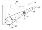
- FIG. 3depicts a rotor blade 50 of a wind turbine.
- the rotor blade 50comprises an axis 52 and a coordinate system aligned thereto, i.e. a blade-fixed coordinate system illustrated exemplarily in FIG. 3 by the y-axis and the z-axis.
- the rotor blade 50 of FIG. 3is provided with an arrangement 300 for state monitoring of the rotor blade.
- the arrangement 300 of FIG. 3comprises 3 (three) strain sensors 302 and an acceleration sensor 312 .
- the strain sensors and the acceleration sensorare connected to an evaluation unit 322 .
- the strain sensors 302are mounted at the blade root 54 of the rotor blade 50 .
- the acceleration sensor 312is mounted at a position 56 which is situated approximately at half the length of the rotor blade 50 .
- the strain sensor or the strain sensorsmay be mounted at an axial distance to the blade root of 5 meters or less.
- the acceleration sensor or the acceleration sensorscan be mounted within a range of ⁇ 5 meters in axial direction from the blade center.
- the axial distance or the axial directionrespectively, refer to the longitudinal axis 52 of the rotor blade 50 .
- the acceleration sensor or the acceleration sensorscan be mounted within a range from the center of the rotor blade in the direction of the tip of the rotor blade.
- the strain sensors 302By means of the strain sensors 302 , the bending moment applied to the blade can be determined. According to embodiments of the present invention, at least one strain sensor 302 is employed, such that the bending moment can be determined in one direction. According to further typical embodiments, at least 3 (three) strain sensors 302 or at least 4 (four) strain sensors 302 can be employed, respectively, in order to determine a bending moment within the y-z plane of the coordinate system depicted in FIG. 3 . With an appropriate arrangement of 2 (two) strain sensors, e.g. at different angular coordinates of the blade root, the bending moments, applied on the rotor blade in 2 (two) directions, typically 2 (two) orthogonal directions, can also be measured by employing 2 (two) sensors. For this purpose, the 2 (two) sensors are typically mounted with their angular coordinates turned by 90°, or mounted with their angular coordinates not turned by 180°, respectively.
- the acceleration sensor 312which is described later with reference to FIGS. 9A and 9B , includes a mass, the acceleration of which is measured in the sensor.
- the employed strain sensors and/or the employed acceleration sensorsmay be fibre-optic sensors.
- the strain or the acceleration of the mass, respectivelyis measured optically by fiber Bragg gratings in a fiber.
- FIG. 4depicts a part of a wind turbine 400 .
- a nacelle 44is disposed on a tower 42 .
- Rotor blades 50are disposed at a rotor hub 46 , such that the rotor (including the rotor hub and the rotor blades) rotates within a plane depicted by a line 452 . Typically, this plane is inclined relatively to the vertical line 402 .
- FIG. 5illustrates a front view of the rotor blades 50 and the rotor hub 46 in the direction of the rotor axis, wherein the coordinates x and y in the blade-fixed coordinate system, the gravitational force or gravitational acceleration g, respectively, and the sensor 312 are shown.
- the acceleration sensor 312measures, among others, the gravitational acceleration g, which is indicated by a curve 601 in FIG. 6 .
- This gravitational accelerationis measured, in the coordinate system according to FIG. 5 , in the y-direction and in the x-direction. Due to the inclination of the rotor, which is depicted in FIG. 4 , in the coordinate system of FIG. 5 , a signal is also superimposed with the gravitational acceleration in the z-direction to a certain extent.
- the gravitational signalis superimposed with the measurement signal 612 depicted in FIG. 6 , which is typically measured in the y-direction depicted in FIG. 5 . By eliminating the gravitational signal in the measurement signal, the signal 712 illustrated in FIG. 7 is obtained.
- Controllers of modern wind turbinestypically include a so-called pitch control, wherein the rotor blade is turned among the axis 52 depicted in FIG. 3 . Accordingly, in a blade-fixed coordinate system, the y-direction depicted in FIG. 5 changes during a rotation of the rotor blade 50 around the axis 52 .
- a transformation into the stationary coordinate systemis performed, wherein the rotation of the rotor, the pitch angle of the rotor blade, and the inclination of the rotor, illustrated by the lines 452 and 402 in FIG. 4 , are taken into account.
- the gravitational accelerationcan be removed from the signal.
- an inverse transformationcan be performed into the coordinate system which is fixed with respect to the rotor hub.
- an accelerationis typically determined which is substantially in parallel to the direction of the wind or substantially in parallel to the rotational axis of the rotor, which is denoted as 2 hereinafter, and an acceleration ⁇ tilde over (y) ⁇ is determined which is orthogonal to 2 and corresponds substantially to the tangential velocity of the rotor blade.
- an acceleration along the x-direction depicted in FIG. 5 or a direction ⁇ tilde over (x) ⁇ , respectively,is negligible for the evaluation.
- the signal or the signals corresponding to an accelerationare integrated over time, particularly integrated twice over time, in order to determine a shift, a change of the position or a change of the location of the acceleration sensor and thereby a corresponding shift or a corresponding change of the location of the rotor blade position.
- the acceleration sensoris assigned a location on the rotor blade. The sensor measures the acceleration at this location of the rotor blade. This acceleration is obtained from the gravitational acceleration, from the rotation of the rotor, and from movement, i.e. deformation (strain) of the rotor blade. By integrating the signal (twice) over time, the shift of this location or the positional change of this location is obtained, respectively.
- the straini.e. a shift or a positional change
- the strain sensors 302 depicted in FIG. 3the bending moment applied to the blade can be determined.
- a quantity for the stiffness or the elasticity of the rotor bladecan bei determined on the basis of the value of the shift or the value of the positional change and the value of the bending moment, respectively.
- the quotient of the bending moment and the shifti.e. the bending moments caused by the shift, is proportional to the stiffness.
- this valueis used for state monitoring of a rotor blade in a wind turbine according to the relationship illustrated in FIG. 1 .
- the accelerationis measured in at least one direction, preferably in the above-described direction, which is substantially parallel to the tangential velocity of the rotor blade.
- a known pitch angle for regular operationi.e. a typical or commonly occurring pitch position
- thiscan be provided by accordingly mounting a one-dimensional acceleration sensor in the rotor blade, i.e. in the blade-fixed coordinate system.
- a bending moment in the corresponding or applicable direction, i.e. in the parallel directioncan also be provided by appropriate mounting of a strain sensor 302 .
- a state monitoring using a one-dimensional acceleration sensor and a strain sensorcan be performed.
- an accelerationis measured in 3 (three) directions, and a strain or a bending moment, respectively, is determined by at least 2 (two) strain sensors along an arbitrary orientation within the plane of the blade root.
- a monitoringcan be performed independently from the pitch angle or along multiple coordinates in any desired coordinate system. The calculation along multiple coordinates may result in a more reliable state monitoring.
- typical orientations of the wear or damage of the rotor bladesare known, in particular these directions can be monitored.
- FIG. 6illustrates a typical example of a signal of the acceleration sensor or the acceleration sensors in the direction of ⁇ tilde over (y) ⁇ , i.e. in a coordinate system which is fixed relative to the rotor hub.
- a value 712is obtained, as illustrated in FIG. 7 .
- This progressioncan be integrated twice over time in order to measure the shift of the rotor blade at the position which corresponds to the position of the acceleration sensor.
- the sinusoidal progression illustrated by the dotted line in FIG. 7corresponds to a positional change of the position in the rotor blade which is caused by the gravitational acceleration exerted on the mass of the rotor blade. In other words: The rotor blade bends due to its self-weight.
- Signals of the acceleration sensor or the acceleration sensors in the ⁇ tilde over (x) ⁇ directiontypically show dynamic characteristics with high frequency components which are caused, for example, by gusts of wind.
- the acceleration signalscan be filtered by their frequency components, wherein, for example, a low-pass filter can be employed.
- FIG. 8illustrates a Fourier transform, wherein the stiffness k is plotted over the frequency f.
- the curve 812exposes a typical progression having a quasi-statical area 821 and a natural frequency 822 .
- a low-pass filterfor frequencies of 0.6 Hz or below, typically 0.4 Hz or below, can be applied to the signals or values of the sensors. At a rotational speed of, for example, 0.2 Hz, this filtering results in an essentially smooth sinusoidal progression for the signal depicted in FIG. 7 .
- signals within the range of the natural frequency 822can be used.
- the natural frequencyis, for example,e within the range of 0.8 Hz to 1.2 Hz.
- the rotor bladeundergoes greater positional deviations, which may result in a better measurement accuracy.
- an evaluationmay be performed with a low-pass filter and a band-pass filter in the vicinity of the natural frequency and separate from each other. By the evaluation in both frequency ranges, i.e. by an additional evaluation within the range of the natural frequency, additional information may be used and thus, an improved measurement accuracy can be achieved.
- FIG. 9Aillustrates an acceleration sensor 312 , wherein a mass 912 is mounted on an optical fiber.
- a housing 902is designed such that upon an acceleration of the mass 912 , a strain occurs, i.e. a relative change of length (elongation or contraction) of the optical fiber 922 .
- the fiber Bragg grating 924is changed. This results in a modified reflection or transmission of the fiber Bragg grating, respectively, with respect to the respective reflected or transported wave lengths.
- This changecan be used as a quantity of the strain of the fiber and, therefore, indirectly as a quantity of the acceleration of the mass 912 .
- An acceleration sensor 312is shown in FIG. 9B .
- 3 (three) of the sensors shown in FIG. 9Aare combined, wherein the rotation of the sensors in the illustration are meant to show a three-dimensional arrangement.
- 3 (three) acceleration sensorare measured within one coordinate system, e.g. within a cartesian coordinate system.
- FIG. 10illustrates a flowchart of a method for state monitoring of a rotor blade of a wind turbine according to embodiments described herein.
- an acceleration of the rotor bladeis measured using a first signal.
- at least one directional component perpendicular to the axis of the rotor bladeis measured.
- a strainis measured using a second signal.
- a positional change of the acceleration sensoris determined in step 1006 , the positional change corresponding to a positional change of the respective rotor blade position.
- a quantity for the stiffness of the rotor blade or for the elasticity of the rotor bladeis obtained in step 1008 . This quantity is used in step 1010 for monitoring the rotor blade state.
- an integration twice over timeis used in order to determine the positional change at the location of the acceleration sensor.
- the accelerationis measured in 3 (three) directions, e.g. directions of a Cartesian coordinate system
- the strainis measured in at least 2 (two) directions, such that a strain with an arbitrary orientation within the plane of the blade root may be determined.
- an averaging over a time period of 1 (one) hour or longermay be performed, in particular an averaging over a time period of one day or longer. Thereby, the measurement accuracy is improved, and the state of the rotor blade can be determined sufficiently, i.e. in good time.
- fibre-optic sensorsare used, wherein particularly sensors having a fiber Bragg grating can be employed.
- fibre-optic acceleration sensorscombined with fibre-optic strain sensors are used.
- a strain sensor at the blade root or in the vicinity thereof, and an acceleration sensor with an axial distance to the blade root of at least half of the blade radiusare used.
Landscapes
- Engineering & Computer Science (AREA)
- Chemical & Material Sciences (AREA)
- Life Sciences & Earth Sciences (AREA)
- Physics & Mathematics (AREA)
- General Physics & Mathematics (AREA)
- General Engineering & Computer Science (AREA)
- Mechanical Engineering (AREA)
- Sustainable Energy (AREA)
- Sustainable Development (AREA)
- Combustion & Propulsion (AREA)
- Analytical Chemistry (AREA)
- Health & Medical Sciences (AREA)
- Biochemistry (AREA)
- General Health & Medical Sciences (AREA)
- Immunology (AREA)
- Pathology (AREA)
- Wind Motors (AREA)
Abstract
Description
Claims (12)
Applications Claiming Priority (4)
| Application Number | Priority Date | Filing Date | Title |
|---|---|---|---|
| DE102012108776.8ADE102012108776A1 (en) | 2012-09-18 | 2012-09-18 | Method and device for monitoring operating states of rotor blades |
| DE102012108776 | 2012-09-18 | ||
| DE102012108776.8 | 2012-09-18 | ||
| PCT/EP2013/068705WO2014044575A1 (en) | 2012-09-18 | 2013-09-10 | Method and device for monitoring operating states of rotor blades |
Publications (2)
| Publication Number | Publication Date |
|---|---|
| US20150211969A1 US20150211969A1 (en) | 2015-07-30 |
| US9316571B2true US9316571B2 (en) | 2016-04-19 |
Family
ID=49209338
Family Applications (1)
| Application Number | Title | Priority Date | Filing Date |
|---|---|---|---|
| US14/427,087ActiveUS9316571B2 (en) | 2012-09-18 | 2013-09-10 | Method and device for monitoring the state of rotor blades |
Country Status (8)
| Country | Link |
|---|---|
| US (1) | US9316571B2 (en) |
| EP (1) | EP2898216B1 (en) |
| CN (1) | CN104641107B (en) |
| CA (1) | CA2884973C (en) |
| DE (1) | DE102012108776A1 (en) |
| DK (1) | DK2898216T3 (en) |
| ES (1) | ES2617903T3 (en) |
| WO (1) | WO2014044575A1 (en) |
Cited By (24)
| Publication number | Priority date | Publication date | Assignee | Title |
|---|---|---|---|---|
| US20170045547A1 (en)* | 2014-04-23 | 2017-02-16 | Oxford University Innovation Limited | Generating timing signals |
| US20170268486A1 (en)* | 2014-12-04 | 2017-09-21 | fos4X GmbH | Method for the individual pitch control of rotor blades of a wind turbine, acceleration sensor for a rotor blade, rotor blade comprising an acceleration sensor, rotor blade of a wind turbine and wind turbine |
| US9846933B2 (en) | 2015-11-16 | 2017-12-19 | General Electric Company | Systems and methods for monitoring components |
| US9869545B2 (en) | 2015-04-15 | 2018-01-16 | General Electric Company | Data acquisition devices, systems and method for analyzing strain sensors and monitoring turbine component strain |
| US9879981B1 (en) | 2016-12-02 | 2018-01-30 | General Electric Company | Systems and methods for evaluating component strain |
| US9909860B2 (en) | 2015-04-15 | 2018-03-06 | General Electric Company | Systems and methods for monitoring component deformation |
| US9953408B2 (en) | 2015-11-16 | 2018-04-24 | General Electric Company | Methods for monitoring components |
| US9967523B2 (en) | 2015-12-16 | 2018-05-08 | General Electric Company | Locating systems and methods for components |
| US20180180030A1 (en)* | 2015-06-30 | 2018-06-28 | Vestas Wind Systems A/S | Method of measuring load on a wind turbine |
| US10012552B2 (en) | 2015-11-23 | 2018-07-03 | General Electric Company | Systems and methods for monitoring component strain |
| US10126119B2 (en) | 2017-01-17 | 2018-11-13 | General Electric Company | Methods of forming a passive strain indicator on a preexisting component |
| US10132615B2 (en) | 2016-12-20 | 2018-11-20 | General Electric Company | Data acquisition devices, systems and method for analyzing passive strain indicators and monitoring turbine component strain |
| DE102017115926A1 (en)* | 2017-07-14 | 2019-01-17 | fos4X GmbH | Sheet bending moment determination with two load sensors per rotor blade and incorporating rotor data |
| US10345179B2 (en) | 2017-02-14 | 2019-07-09 | General Electric Company | Passive strain indicator |
| US10451499B2 (en) | 2017-04-06 | 2019-10-22 | General Electric Company | Methods for applying passive strain indicators to components |
| US10502551B2 (en) | 2017-03-06 | 2019-12-10 | General Electric Company | Methods for monitoring components using micro and macro three-dimensional analysis |
| US10539119B2 (en) | 2017-07-10 | 2020-01-21 | WindESCo, Inc. | System and method for augmenting control of a wind turbine assembly |
| US20200158092A1 (en)* | 2016-03-14 | 2020-05-21 | Ventus Engineering GmbH | Method of condition monitoring one or more wind turbines and parts thereof and performing instant alarm when needed |
| US10697760B2 (en) | 2015-04-15 | 2020-06-30 | General Electric Company | Data acquisition devices, systems and method for analyzing strain sensors and monitoring component strain |
| US10872176B2 (en) | 2017-01-23 | 2020-12-22 | General Electric Company | Methods of making and monitoring a component with an integral strain indicator |
| US11105588B2 (en) | 2014-01-14 | 2021-08-31 | Mcree's Multi Services, Llc | Embedded cant indicator for rifles |
| US11313673B2 (en) | 2017-01-24 | 2022-04-26 | General Electric Company | Methods of making a component with an integral strain indicator |
| US20230220835A1 (en)* | 2020-02-23 | 2023-07-13 | fos4X GmbH | Method for monitoring the state of the powertrain or tower of a wind turbine, and wind turbine |
| US20230258162A1 (en)* | 2020-08-14 | 2023-08-17 | Eologix Sensor Technology Gmbh | Measuring device for wind turbines |
Families Citing this family (28)
| Publication number | Priority date | Publication date | Assignee | Title |
|---|---|---|---|---|
| CN104033334B (en)* | 2014-06-27 | 2016-11-23 | 国电联合动力技术有限公司 | A kind of wind generator set blade vibration-reducing control method and system |
| DE102014218266A1 (en)* | 2014-09-12 | 2016-03-17 | Robert Bosch Gmbh | Method and control device for detecting a load on a rotor blade of a wind energy plant |
| DE102014117916A1 (en)* | 2014-12-04 | 2016-06-09 | fos4X GmbH | Method for monitoring a wind turbine, acceleration sensor for a rotor blade, and rotor blade with acceleration sensor |
| DE102014117915A1 (en)* | 2014-12-04 | 2016-06-09 | fos4X GmbH | Method for monitoring a wind turbine, method for detecting ice on a wind turbine, acceleration sensor for a rotor blade, rotor blade with acceleration sensor, and profile for a rotor blade |
| US9932853B2 (en)* | 2015-04-28 | 2018-04-03 | General Electric Company | Assemblies and methods for monitoring turbine component strain |
| US10612524B2 (en) | 2015-06-30 | 2020-04-07 | Vestas Wind Systems A/S | Blade load sensing system for a wind turbine |
| CN105424333B (en)* | 2015-11-06 | 2017-11-14 | 中国科学院工程热物理研究所 | A kind of monitoring of pneumatic equipment bladess on-site damage and recognition methods |
| CN108431408A (en)* | 2015-11-11 | 2018-08-21 | Lm Wp 专利控股有限公司 | Flexiblity monitor system for wind turbine blade |
| DE102016112633A1 (en)* | 2016-07-11 | 2018-01-11 | Wobben Properties Gmbh | Torsion angle measurement of a rotor blade |
| DE102016117191A1 (en)* | 2016-09-13 | 2018-03-15 | fos4X GmbH | Method and device for determining loads on a tower of a wind energy plant |
| US10337935B2 (en)* | 2016-12-12 | 2019-07-02 | Sikorsky Aircraft Corporation | Systems and methods for integrated, multi-functional, fault tolerant sensing and communication |
| US20210148336A1 (en)* | 2017-06-20 | 2021-05-20 | Vestas Wind Systems A/S | A method for determining wind turbine blade edgewise load recurrence |
| DE102017115927A1 (en)* | 2017-07-14 | 2019-01-17 | fos4X GmbH | Strain and vibration measuring system for monitoring rotor blades |
| WO2019038710A1 (en) | 2017-08-24 | 2019-02-28 | Suzlon Energy Ltd. | Sensor arrangement for sensing bending moments in an elongate component; elongate component; sensor system and wind turbine |
| CN108733079B (en)* | 2018-06-19 | 2021-08-10 | 上海扩博智能技术有限公司 | Method and system for determining flight path of fan through automatic inspection by unmanned aerial vehicle |
| DE102018116941B4 (en) | 2018-07-12 | 2022-10-06 | fos4X GmbH | Device and method for detecting the accumulation or the type of ice on a rotor blade of a rotor of a wind turbine |
| DE102018127417A1 (en)* | 2018-11-02 | 2020-05-07 | fos4X GmbH | Modeling and forecasting wind flow using fiber optic sensors in wind turbines |
| CN109578223A (en)* | 2019-01-16 | 2019-04-05 | 远景能源(江苏)有限公司 | A kind of device and corresponding detection method of the rigidity for pilot blade |
| CN110083968B (en)* | 2019-05-08 | 2022-09-27 | 中国船舶重工集团公司第七0三研究所 | Compressor characteristic prediction method based on correction of gas seal leakage influence numerical model |
| DE102019114529A1 (en)* | 2019-05-29 | 2020-12-03 | fos4X GmbH | Modeling and prediction of wake vortices and wind shear with fiber optic sensors in wind turbines |
| DE102019135628A1 (en)* | 2019-12-20 | 2021-06-24 | fos4X GmbH | Method for determining a remaining useful life of a wind turbine and wind turbine |
| CN113464377B (en)* | 2020-03-31 | 2022-11-08 | 新疆金风科技股份有限公司 | Wind turbine impeller detection system and method |
| EP3961177B1 (en)* | 2020-08-25 | 2022-06-15 | AIRBUS HELICOPTERS DEUTSCHLAND GmbH | A measurement apparatus for determining a bending moment |
| CN114790967A (en)* | 2021-01-25 | 2022-07-26 | 上海拜安传感技术有限公司 | Method and device for monitoring fan blade of wind driven generator, storage medium and wind driven generator |
| CN113404652A (en)* | 2021-06-09 | 2021-09-17 | 东方电气集团科学技术研究院有限公司 | Method for monitoring state of blade of wind generating set in severe environment |
| CN114104721B (en)* | 2021-12-29 | 2023-07-25 | 武汉华星光电半导体显示技术有限公司 | Clamping device |
| DE102022107681A1 (en)* | 2022-03-31 | 2023-10-05 | Harting Ag | Condition monitoring device, rotor blade and wind turbine with it |
| CN114458551A (en)* | 2022-04-12 | 2022-05-10 | 华电电力科学研究院有限公司 | Load data acquisition device of wind driven generator and wind driven generator system |
Citations (19)
| Publication number | Priority date | Publication date | Assignee | Title |
|---|---|---|---|---|
| US20040057828A1 (en) | 2002-09-23 | 2004-03-25 | Bosche John Vanden | Wind turbine blade deflection control system |
| US20050276696A1 (en) | 2004-06-10 | 2005-12-15 | Lemieux David L | Methods and apparatus for rotor blade ice detection |
| WO2007131489A1 (en) | 2006-05-15 | 2007-11-22 | Igus - Innovative Technische Systeme Gmbh | Method for monitoring the load on rotor blades of wind energy installations |
| CN101482448A (en) | 2008-01-10 | 2009-07-15 | 西门子公司 | Method for determining fatigue load of a wind turbine and for fatigue load control, and wind turbines therefor |
| US20090246019A1 (en) | 2007-05-04 | 2009-10-01 | Mark Volanthen | Wind turbine monitoring |
| EP2112375A2 (en) | 2008-03-28 | 2009-10-28 | Insensys Limited | Wind turbine icing detection |
| WO2010046403A2 (en) | 2008-10-23 | 2010-04-29 | Vestas Wind Systems A/S | A wind turbine and a method for monitoring a wind turbine |
| US20100135801A1 (en)* | 2009-10-29 | 2010-06-03 | General Electric Company | Systems and methods for testing a wind turbine pitch control system |
| US20110041617A1 (en)* | 2008-05-02 | 2011-02-24 | Alliance For Sustainable Energy, Llc | Base excitation testing system using spring elements to pivotally mount wind turbine blades |
| US20110265575A1 (en)* | 2010-07-29 | 2011-11-03 | Glen Peter Koste | System for estimating a condition of non-conductive hollow structure exposed to a lightning strike |
| CN102279018A (en) | 2010-04-30 | 2011-12-14 | 通用电气公司 | Method for measuring an operational parameter of a wind turbine and measuring device |
| CN102330645A (en) | 2011-09-19 | 2012-01-25 | 吴建华 | Health monitoring system and method for wind generator system structure |
| CN102648345A (en) | 2009-10-08 | 2012-08-22 | 维斯塔斯风力系统有限公司 | Control method for a wind turbine |
| US8511177B1 (en)* | 2011-12-15 | 2013-08-20 | Shaw Shahriar Makaremi | Blade condition monitoring system |
| US20130255398A1 (en)* | 2010-12-30 | 2013-10-03 | Morten Philipsen | Wind turbine blade with optical sensor system |
| US20140020465A1 (en)* | 2012-07-23 | 2014-01-23 | Hans Laurberg | Monitoring arrangement |
| US8757003B1 (en)* | 2011-12-15 | 2014-06-24 | Shaw Shahriar Makaremi | Multi-frequency-band blade condition monitoring system |
| US8820149B2 (en)* | 2011-12-30 | 2014-09-02 | Prüftechnik Dieter Busch AG | Method for oscillation measurement on rotor blades or wind power installations |
| US20150000404A1 (en)* | 2011-10-26 | 2015-01-01 | Robert Bosch Gmbh | Method for determining mechanical damage to a rotor blade of a wind turbine |
- 2012
- 2012-09-18DEDE102012108776.8Apatent/DE102012108776A1/ennot_activeWithdrawn
- 2013
- 2013-09-10DKDK13763023.2Tpatent/DK2898216T3/enactive
- 2013-09-10CACA2884973Apatent/CA2884973C/enactiveActive
- 2013-09-10WOPCT/EP2013/068705patent/WO2014044575A1/enactiveApplication Filing
- 2013-09-10ESES13763023.2Tpatent/ES2617903T3/enactiveActive
- 2013-09-10EPEP13763023.2Apatent/EP2898216B1/enactiveActive
- 2013-09-10CNCN201380048670.4Apatent/CN104641107B/enactiveActive
- 2013-09-10USUS14/427,087patent/US9316571B2/enactiveActive
Patent Citations (21)
| Publication number | Priority date | Publication date | Assignee | Title |
|---|---|---|---|---|
| US20040057828A1 (en) | 2002-09-23 | 2004-03-25 | Bosche John Vanden | Wind turbine blade deflection control system |
| US20050276696A1 (en) | 2004-06-10 | 2005-12-15 | Lemieux David L | Methods and apparatus for rotor blade ice detection |
| WO2007131489A1 (en) | 2006-05-15 | 2007-11-22 | Igus - Innovative Technische Systeme Gmbh | Method for monitoring the load on rotor blades of wind energy installations |
| CN101460901A (en) | 2006-05-15 | 2009-06-17 | 易格斯创新技术系统有限公司 | Method for monitoring the load on rotor blades of wind energy installations |
| US20090246019A1 (en) | 2007-05-04 | 2009-10-01 | Mark Volanthen | Wind turbine monitoring |
| CN101482448A (en) | 2008-01-10 | 2009-07-15 | 西门子公司 | Method for determining fatigue load of a wind turbine and for fatigue load control, and wind turbines therefor |
| US20090180875A1 (en) | 2008-01-10 | 2009-07-16 | Per Egedal | Method for determining fatigue load of a wind turbine and for fatigue load control, and wind turbines therefor |
| EP2112375A2 (en) | 2008-03-28 | 2009-10-28 | Insensys Limited | Wind turbine icing detection |
| US20110041617A1 (en)* | 2008-05-02 | 2011-02-24 | Alliance For Sustainable Energy, Llc | Base excitation testing system using spring elements to pivotally mount wind turbine blades |
| WO2010046403A2 (en) | 2008-10-23 | 2010-04-29 | Vestas Wind Systems A/S | A wind turbine and a method for monitoring a wind turbine |
| CN102648345A (en) | 2009-10-08 | 2012-08-22 | 维斯塔斯风力系统有限公司 | Control method for a wind turbine |
| US20100135801A1 (en)* | 2009-10-29 | 2010-06-03 | General Electric Company | Systems and methods for testing a wind turbine pitch control system |
| CN102279018A (en) | 2010-04-30 | 2011-12-14 | 通用电气公司 | Method for measuring an operational parameter of a wind turbine and measuring device |
| US20110265575A1 (en)* | 2010-07-29 | 2011-11-03 | Glen Peter Koste | System for estimating a condition of non-conductive hollow structure exposed to a lightning strike |
| US20130255398A1 (en)* | 2010-12-30 | 2013-10-03 | Morten Philipsen | Wind turbine blade with optical sensor system |
| CN102330645A (en) | 2011-09-19 | 2012-01-25 | 吴建华 | Health monitoring system and method for wind generator system structure |
| US20150000404A1 (en)* | 2011-10-26 | 2015-01-01 | Robert Bosch Gmbh | Method for determining mechanical damage to a rotor blade of a wind turbine |
| US8511177B1 (en)* | 2011-12-15 | 2013-08-20 | Shaw Shahriar Makaremi | Blade condition monitoring system |
| US8757003B1 (en)* | 2011-12-15 | 2014-06-24 | Shaw Shahriar Makaremi | Multi-frequency-band blade condition monitoring system |
| US8820149B2 (en)* | 2011-12-30 | 2014-09-02 | Prüftechnik Dieter Busch AG | Method for oscillation measurement on rotor blades or wind power installations |
| US20140020465A1 (en)* | 2012-07-23 | 2014-01-23 | Hans Laurberg | Monitoring arrangement |
Non-Patent Citations (3)
| Title |
|---|
| Office Action, Germany Patent Application DE102012108776.8, 10 Pages, Date of Mailing Jun. 6, 2013. |
| Search Report and Written Opinion, PCT/EP2013/068705, 10 Pages, Date of Mailing Jan. 7, 2014. |
| Written Opinion mailed Jan. 7, 2014 for PCT Application No. PCT/EP2013/068705. |
Cited By (35)
| Publication number | Priority date | Publication date | Assignee | Title |
|---|---|---|---|---|
| US11768057B2 (en) | 2014-01-14 | 2023-09-26 | Mcree's Multi Services, Llc | Embedded cant indicator for rifles |
| US11105588B2 (en) | 2014-01-14 | 2021-08-31 | Mcree's Multi Services, Llc | Embedded cant indicator for rifles |
| US9952247B2 (en)* | 2014-04-23 | 2018-04-24 | Oxford University Innovation Limited | Generating timing signals |
| US20170045547A1 (en)* | 2014-04-23 | 2017-02-16 | Oxford University Innovation Limited | Generating timing signals |
| US20170268486A1 (en)* | 2014-12-04 | 2017-09-21 | fos4X GmbH | Method for the individual pitch control of rotor blades of a wind turbine, acceleration sensor for a rotor blade, rotor blade comprising an acceleration sensor, rotor blade of a wind turbine and wind turbine |
| US10655601B2 (en)* | 2014-12-04 | 2020-05-19 | fos4X GmbH | Method for the individual pitch control of rotor blades of a wind turbine, and wind turbines |
| US9869545B2 (en) | 2015-04-15 | 2018-01-16 | General Electric Company | Data acquisition devices, systems and method for analyzing strain sensors and monitoring turbine component strain |
| US10697760B2 (en) | 2015-04-15 | 2020-06-30 | General Electric Company | Data acquisition devices, systems and method for analyzing strain sensors and monitoring component strain |
| US9909860B2 (en) | 2015-04-15 | 2018-03-06 | General Electric Company | Systems and methods for monitoring component deformation |
| US10605233B2 (en)* | 2015-06-30 | 2020-03-31 | Vestas Wind Systems A/S | Method of measuring load on a wind turbine |
| US20180180030A1 (en)* | 2015-06-30 | 2018-06-28 | Vestas Wind Systems A/S | Method of measuring load on a wind turbine |
| US9953408B2 (en) | 2015-11-16 | 2018-04-24 | General Electric Company | Methods for monitoring components |
| US9846933B2 (en) | 2015-11-16 | 2017-12-19 | General Electric Company | Systems and methods for monitoring components |
| US10012552B2 (en) | 2015-11-23 | 2018-07-03 | General Electric Company | Systems and methods for monitoring component strain |
| US9967523B2 (en) | 2015-12-16 | 2018-05-08 | General Electric Company | Locating systems and methods for components |
| US12044208B2 (en) | 2016-03-14 | 2024-07-23 | Ventus Engineering GmbH | Method of condition monitoring one or more wind turbines and parts thereof and performing instant alarm when needed |
| US11549492B2 (en)* | 2016-03-14 | 2023-01-10 | Ventus Engineering GmbH | Method of condition monitoring one or more wind turbines and parts thereof and performing instant alarm when needed |
| US20200158092A1 (en)* | 2016-03-14 | 2020-05-21 | Ventus Engineering GmbH | Method of condition monitoring one or more wind turbines and parts thereof and performing instant alarm when needed |
| US9879981B1 (en) | 2016-12-02 | 2018-01-30 | General Electric Company | Systems and methods for evaluating component strain |
| US10132615B2 (en) | 2016-12-20 | 2018-11-20 | General Electric Company | Data acquisition devices, systems and method for analyzing passive strain indicators and monitoring turbine component strain |
| US10126119B2 (en) | 2017-01-17 | 2018-11-13 | General Electric Company | Methods of forming a passive strain indicator on a preexisting component |
| US10872176B2 (en) | 2017-01-23 | 2020-12-22 | General Electric Company | Methods of making and monitoring a component with an integral strain indicator |
| US11313673B2 (en) | 2017-01-24 | 2022-04-26 | General Electric Company | Methods of making a component with an integral strain indicator |
| US10345179B2 (en) | 2017-02-14 | 2019-07-09 | General Electric Company | Passive strain indicator |
| US10502551B2 (en) | 2017-03-06 | 2019-12-10 | General Electric Company | Methods for monitoring components using micro and macro three-dimensional analysis |
| US10451499B2 (en) | 2017-04-06 | 2019-10-22 | General Electric Company | Methods for applying passive strain indicators to components |
| US11300102B2 (en) | 2017-07-10 | 2022-04-12 | WindESCo, Inc. | System and method for augmenting control of a wind turbine assembly |
| US10539119B2 (en) | 2017-07-10 | 2020-01-21 | WindESCo, Inc. | System and method for augmenting control of a wind turbine assembly |
| DE102017115926B4 (en) | 2017-07-14 | 2022-03-17 | fos4X GmbH | Blade bending moment determination with two load sensors per rotor blade and including rotor data |
| US11371486B2 (en)* | 2017-07-14 | 2022-06-28 | fos4X GmbH | Determining a blade bending moment with two load sensors per rotor blade and taking rotor data into consideration |
| DE102017115926A1 (en)* | 2017-07-14 | 2019-01-17 | fos4X GmbH | Sheet bending moment determination with two load sensors per rotor blade and incorporating rotor data |
| EP3652431B1 (en) | 2017-07-14 | 2024-07-24 | VC VIII Polytech Holding ApS | Determiniing a blade bending moment with two load sensors per rotor blade and taking rotor data into consideration |
| US20230220835A1 (en)* | 2020-02-23 | 2023-07-13 | fos4X GmbH | Method for monitoring the state of the powertrain or tower of a wind turbine, and wind turbine |
| US12098700B2 (en)* | 2020-02-23 | 2024-09-24 | Vc Viii Polytech Holding Aps | Method for monitoring the state of the powertrain or tower of a wind turbine, and wind turbine |
| US20230258162A1 (en)* | 2020-08-14 | 2023-08-17 | Eologix Sensor Technology Gmbh | Measuring device for wind turbines |
Also Published As
| Publication number | Publication date |
|---|---|
| EP2898216A1 (en) | 2015-07-29 |
| DK2898216T3 (en) | 2017-03-13 |
| CN104641107B (en) | 2016-10-12 |
| CA2884973A1 (en) | 2014-03-27 |
| ES2617903T3 (en) | 2017-06-20 |
| WO2014044575A1 (en) | 2014-03-27 |
| CN104641107A (en) | 2015-05-20 |
| CA2884973C (en) | 2016-06-21 |
| EP2898216B1 (en) | 2016-12-07 |
| DE102012108776A1 (en) | 2014-03-20 |
| US20150211969A1 (en) | 2015-07-30 |
Similar Documents
| Publication | Publication Date | Title |
|---|---|---|
| US9316571B2 (en) | Method and device for monitoring the state of rotor blades | |
| US20190203698A1 (en) | Method and device for determining loads on a wind turbine tower | |
| CN101660487B (en) | Method and apparatus for load measurement in a wind turbine | |
| CN103261680B (en) | System and method for identifying tower strike likelihood when a rotor blade strikes a tower of a wind turbine | |
| EP3317513B1 (en) | Method of measuring load on a wind turbine | |
| EP2593672B1 (en) | Ice detection method and system for wind turbine blades | |
| DK2075561T3 (en) | Methods and apparatus for error reduction in rotorbelastningsmålinger | |
| US20150240788A1 (en) | Method for detecting damage of wind turbine blade and wind turbine | |
| CN107820541B (en) | Wind turbine blade load sensing system | |
| EP2112375A2 (en) | Wind turbine icing detection | |
| EP2593671B1 (en) | Method and system for monitoring bending strain on wind turbine blades | |
| US20110285129A1 (en) | wind turbine and a method for monitoring a wind turbine | |
| US20100004878A1 (en) | Wind turbine monitoring | |
| JP6242830B2 (en) | Wind turbine blade damage detection method and wind turbine | |
| CN102032892A (en) | Azimuth angle measurement system and method for operating the same | |
| KR20190021433A (en) | Measurement of twist angle of rotor blade | |
| US10697440B2 (en) | Method of detecting damage of wind turbine blade, and wind turbine | |
| GB2459726A (en) | A method of detecting ice formation on wind turbine blades and other methods of wind turbine monitoring | |
| CN102459888A (en) | Method for balancing a wind turbine | |
| DK2992209T3 (en) | METHOD AND SYSTEM FOR MONITORING A WINDMILL AND WINDMILL | |
| EP3317628B1 (en) | A method and a device for determining torsional deformation in a drivetrain | |
| DK2923080T3 (en) | PROCEDURE FOR OPERATING A WIND ENERGY INSTALLATION AND WIND ENERGY INSTALLATION | |
| Marwitz et al. | Relations between the quality of identified modal parameters and measured data obtained by structural monitoring |
Legal Events
| Date | Code | Title | Description |
|---|---|---|---|
| AS | Assignment | Owner name:TECHNISCHE UNIVERSITAET MUENCHEN, GERMANY Free format text:ASSIGNMENT OF ASSIGNORS INTEREST;ASSIGNORS:MUELLER, MATHIAS;WOJTECH, ROLF;BUCK, THORBJOERN;REEL/FRAME:035183/0475 Effective date:20150226 | |
| STCF | Information on status: patent grant | Free format text:PATENTED CASE | |
| MAFP | Maintenance fee payment | Free format text:PAYMENT OF MAINTENANCE FEE, 4TH YR, SMALL ENTITY (ORIGINAL EVENT CODE: M2551); ENTITY STATUS OF PATENT OWNER: SMALL ENTITY Year of fee payment:4 | |
| AS | Assignment | Owner name:FOS4X GMBH, GERMANY Free format text:NUNC PRO TUNC ASSIGNMENT;ASSIGNOR:TECHNISCHE UNIVERSITAET MUENCHEN;REEL/FRAME:051865/0736 Effective date:20191107 | |
| MAFP | Maintenance fee payment | Free format text:PAYMENT OF MAINTENANCE FEE, 8TH YR, SMALL ENTITY (ORIGINAL EVENT CODE: M2552); ENTITY STATUS OF PATENT OWNER: SMALL ENTITY Year of fee payment:8 | |
| AS | Assignment | Owner name:VC VIII POLYTECH HOLDING APS, DENMARK Free format text:ASSIGNMENT OF ASSIGNORS INTEREST;ASSIGNOR:FOS4X GMBH;REEL/FRAME:064897/0939 Effective date:20230904 | |
| AS | Assignment | Owner name:VC VIII POLYTECH HOLDING APS, DENMARK Free format text:CORRECTIVE ASSIGNMENT TO CORRECT THE TYPOGRAPHICAL ERROR IN STRRET ADDRESS OF ASSIGNEE-SHOULD BE "INDUSTRIVEJ" NOT "INDUSTRIEVEJ" PREVIOUSLY RECORDED AT REEL: 064897 FRAME: 0939. ASSIGNOR(S) HEREBY CONFIRMS THE ASSIGNMENT;ASSIGNOR:FOS4X GMBH;REEL/FRAME:065578/0741 Effective date:20230409 |